Embed Size (px)
Citation preview

1
A Novel Wireless Local Positioning System via
a Merger of DS-CDMA and Beamforming:
Probability-of-Detection Performance Analysis
under Array Perturbations
Hui Tong and Seyed A. Zekavat
Dept. of ECE, Michigan Tech. University, Houghton, MI, 49931
Phone: 906-487-1944, 906-487-2071, e-mail: [email protected], [email protected]
Abstract
This Paper1 investigates the Probability-of-Detection (POD) performance of a novel Wireless Local
Positioning System (WLPS2) realized via Direct Sequence Code Division Multiple Access (DS-CDMA)
and beamforming techniques. The proposed WLPS has unique signaling schemes that discriminate
it from the traditional wireless systems and allows the WLPS to have many civilian and military
applications. The WLPS consists of two main parts: (1) the detecting unit, a base station carried by
a mobile unit defined as Dynamic Base Station (DBS), and (2) the being detected unit, a transponder
(TRX) that is mounted on the targets, each assigned a unique identification code (ID code). Each DBS
should be capable of detecting and locating all available TRXs in its coverage area. As a result, the
main complexity of this system is focused at the DBS receiver.
In this work, we introduce WLPS structure, and both theoretically and numerically compute,
and compare the Probability-of-Detection performance of the DBS receiver realized by a merger of
DS-CDMA and antenna arrays. We also analyze and simulate theperformance of this system under
perturbations in the DBS antenna array vector. The simulations are particularly performed for vehicular
collision avoidance applications.
This work is supported by the US NSF grant ECS-04274301Portions of this paper were previously reported in [1]–[3].2The WLPS US Patent is pending by Michigan Tech. University.
April 19, 2005 DRAFT

2
Index Terms
Wireless Local Positioning System, DS-CDMA, Beamforming,perturbation analysis, vehicle col-
lision avoidance.
I. I NTRODUCTION
Historically, positioning was developed for navigationalpurposes with a wide variety of
civilian and military applications, and they fall into two main categories, Global Positioning
Systems (GPS) and Local Positioning Systems (LPS) [4]–[6].GPS is a precise, all-weather,
24 hour satellite based positioning system mainly developed for direction finding and naviga-
tion [7]. However, GPS has the following problems: (1) its signal does not penetrate into the
buildings; hence, it does not perform at indoor areas, (2) itlooses its precision in rich scattering
environments such as urban areas, (3) it is mainly suitable for navigation and for tracking
or command purposes, it should be merged with a communication system for transmission of
position information from the GPS to a center (e.g., commandcenter in defense applications),
and (4) it is yet expensive.
Local positioning systems (LPS) fall primarily into two main categories [8]: (1) Self Posi-
tioning: A mobile device finds its own instantaneous location with respect to a fixed point, e.g.,
the starting point or a beacon node, and (2) Remote Positioning: A mobile device finds the
instantaneous positions of other objects (mobiles) with respect to its own position. The Wireless
Local Positioning System (WLPS) introduced in this paper is aremote positioning system with
active targets capable of detecting and locating targets within several hundred meters in a dynamic
environment [1]–[3].
In the quest for wireless positioning, different systems have been developed or are under de-
velopment. For example, radar systems are used to find the position of targets in the surrounding
areas via transmission of a short burst of energy and processing its reflection from the targets
[9] [10]. The ability of radars to detect the desired targetsis hindered by clutters or reflections
from undesirable objects and interfering radars, which areinevitable in typical indoor and urban
areas, rendering radar systems impractical [11] [1]. Another example is a vision system that
April 19, 2005 DRAFT

3
uses video signals collected from a camera to recognize targets and estimate positions [12].
Such systems, including Chrysler’s mobile positioning system, face major limitations at night
and in severe weather conditions such as intense rain, snow and fog.
The Wireless Local Positioning System (WLPS) introduced in this paper consists of: (1) a
base station in each monitoring mobile, which serves as a non-static or Dynamic Base Station
(DBS), and (2) a transponder (TRX) in target mobiles, which acts as active targets. Unique
IDentification (ID) codes are assigned to each target. DBS transmits a short pulse containing an
ID Request (IDR) signal to all targets located in its vicinity,and it does not transmit within two
consecutive IDRs called ID request Repetition Time (IRT ). The targets respond to that signal
by transmitting their ID codes back to the DBS. DBS recognizes each target by its ID code,
and then positions, tracks and monitors those targets. Positioning is realized via calculating
the Time-of-Arrival (TOA) and the Direction-of-Arrival (DOA). TOA is defined as the time
difference between transmission of the ID request signal and reception of the corresponding
TRX ID.
The performance of WLPS system depends on two main variables:a) Probability-of-Detection
(POD) of the ID of each TRX, and b) accuracy of positioning, which is a function of the
estimation of TOA and DOA. Both of these parameters are critical for the performance of WLPS
system. In this paper, we focus on the Probability-of-Detection performance of the WLPS. The
positioning performance of WLPS primarily depends on the development of DOA estimation
techniques. These techniques that are unique for WLPS signaling method will be addressed in
our future studies.
Many local positioning systems via active targets have beenintroduced in the literature.
Examples include: (1) Airborne traffic alert and collision avoidance (TCAS) systems [13] [14]
developed for future air navigation systems (FANS) [15] usetransponders at airplanes (active
targets) for positioning purposes. These systems use the radar principles for range resolution with
a range of 10-40 miles [16] which leads to a limited capacity suitable for those applications.
The technique used in TCAS is not feasible for wireless channels, which experience multi-path
fading and interference effects, and cover a range of 0.1-1 mile in many applications; (2) Cell
April 19, 2005 DRAFT

4
phone positioning systems may exploit a triangulation technique [17] to estimate subscriber’s
position. In order to achieve a reasonable positioning accuracy (around100m), the subscriber’s
signal can be received by at least three base stations. But, this number of base stations might
not be available at all times. In addition, experimental results show that the capability of this
system is limited by multipath environments [18]. A merger of area power intensity map and
directional antennas may also be utilized for cell phone positioning purposes [19]. This approach
requires detailed information that constrains to static (as opposed to dynamic) positioning; (3)
In tagged local positioning systems (TLPS), mobiles (active targets) transmit periodic signals at
all times, and static base stations receive those signals and locate the targets via a triangulation
technique [6]. In order to increase its robustness to multipath effects and increase its accuracy,
this system utilizes additional readers and reference tags. These systems are limited to a relatively
fixed environment [20]; and (4) In WLAN positioning systems, atriangulation technique is used
by mobile nodes for positioning purposes. In order to perform triangulation, WLAN positioning
requires a number of nodes to be involved in the positioning process [21]. Hence, positioning
process can not be performed independently by each node, which limits the applications of these
positioning systems.
In the WLPS introduced in this paper, each DBS is capable of positioning all TRXs in its
coverage area. Moreover, the DBS does not need additional prior environmental information.
Hence, WLPS is not limited to the fixed base station. In addition, via the application of wireless
signaling schemes such as Code Division Multiple Access (CDMA), diversity combining and
beamforming, the interference and multipath fading effects can be reduced and the probability of
detection increases. The WLPS can be defined as a node in MobileAdhoc Network (MANET)
with a variety of applications in security systems (e.g., inindoor security via implementation
of DBS and TRX on security guards and just TRX on people entering the building), vehicle
collision avoidance system and multi robot control (e.g., by implementing the DBS and TRX
on all vehicles or robots [1]), and defense (e.g., for command control and tracking, by imple-
mentation of DBS on the central command and control, DBS and TRX on all commanders and
TRX on soldiers). The coverage area of WLPS can be increased viamultiple-hop localization
April 19, 2005 DRAFT

5
techniques [2] [22] [23].
In this work, we investigate the realization of this system via standard transmitters and
receivers (i.e., simple modulators and demodulators) as well as Direct Sequence CDMA (DS-
CDMA) receivers with and without antenna arrays and beamforming (BF) techniques, and we
compare their Probability-Of-Detection,Pd, performance. In DS-CDMA the transmitted symbol
is multiplied in a spreading code in the time domain. Orthogonal spreading codes maintain the
orthogonality between the signals transmitted from different TRXes. In addition, multipath fading
effects are reduced by exploiting path diversity at the DS-CDMA receiver. This technique alone
enhances the Probability-of-Detection (POD) performanceof the DBS receiver. A merger of DS-
CDMA with Spatial Division Multiple Access (SDMA) highly enhances the performance of the
DBS. SDMA is accomplished by employing directionality via antenna arrays at the DBS receiver.
These antenna arrays are required for DOA estimation as well. Our simulation depicts that by
a proper selection ofIRT , both DS-CDMA and standard Rake receivers with conventional BF
lead to a high POD performance. Here, we particularly perform the simulations for vehicular
collision avoidance (road safety) applications of WLPS.
In real applications, perturbation of the array weight vector due to effects such as sensor posi-
tion errors, gain errors, phase errors, mutual coupling between sensors, imperfect channel phase
estimation, and different cable length for each sensor degrades the receiver performance [24] [25].
Synthesizing all these effects leads to an additive random Gaussian error on the array weight
vector [26]. In this work, we also study the performance degradation (POD and capacity) caused
by these perturbation effects.
The paper is organized as follows: Section II introduces theWLPS structure. Section III
discusses the theoretical analysis of the system performance for different system configurations
as well as the perturbation effect. Section IV represents the simulation and analytical results.
Section V concludes the paper. A table of abbreviations usedthroughout this paper is provided
in Table I.
April 19, 2005 DRAFT

6
TABLE I
TABLE OF ABBREVIATIONS
BF BeamformingDBS Dynamic Base StationDOA Direction of Arrival
DS-CDMA Direct Sequence Code Division Multiple AccessGPS Global Positioning SystemIDR ID Request SignalIRT ID Request Repetition TimeLPS Local Positioning SystemPOD Probability-of-Detection
SDMA Spatial Division Multiple AccessTOA Time Of ArrivalTRX Transponder
WLPS Wireless Local Positioning System
τDBS
IRT
ID request signal transmitted by a specific DBS: This message will be transmitted via a CDMA scheme every IRT Received signal (ID code) from a mobile (TRX) which is
transmitted via a MA scheme.
τTRX
TOA calculation
Fig. 1. Transmission of IDR and reception from TRX in DBS. Assuming a Pseudo Random ID codes, the number of the bitsin the code represents the maximum capacity of the WLPS.
II. WLPS STRUCTURE
The two WLPS main parts include: A dynamic base station (DBS) and a transponder (TRX).
The DBS transmitter generates an ID code request (IDR) signal every IRT (ID request repetition
time) to all TRXs in the coverage area; then, it waits to receive a response back from the TRX
within IRT (see Fig. 1). TRX transmits a unique ID code as soon as it detects the IDR signal
transmitted by the DBS. The ID code is selected from simple pseudo random codes which consist
of +1 and -1. Hence, the number of bits in the code depicts the maximum capacity of the WLPS.
Depending on the application, the ID code can be assigned permanently or can be assigned by
the DBS transmitter. The structure of DBS is shown in Fig. 2.
In a WLPS structure, each DBS communicates with a number of TRX inits coverage area
April 19, 2005 DRAFT

7
Transmitter
AntennaOmni−Directional Modulator (If it is required)
MA Scheme ID Request (IDR)Signal Generator
MA RCVR andDiversity Combiner
Adaptive Beamformerand DOA Finder
ID Detector and Position FinderAntenna Array
Receiver
Fig. 2. DBS structure
simultaneously. This is the same as usual cellular communication systems. However, in contrast
to cellular systems, in WLSP each TRX communicates with a number of DBS simultaneously as
well. In addition, the time of transmission and reception would be different at the DBS, as shown
in Fig. 1. Moreover, the whole DBS and TRX use different transmission frequencies. Thus, the
overall system is considered as a time division duplex (TDD)-frequency division duplex (FDD),
that is, hybrid TDD/FDD communication system (differ from cellular systems that are either
TDD or FDD). This allows WLPS to reduce the interference effects via a proper selection of
IRT .
The minimum allowable value forIRT (IRTmin) is calculated to avoid range ambiguity: If
the response to each IDR signal is received in DBS withinIRT , mobile range is calculated
correctly; however, if it is received after the next IDR transmission, the range is not correctly
calculated. Here,IRT is a function of the maximum coverage or the maximum rangeRmax.
The minimum allowableIRT corresponds to:
IRTmin = 2Tmax + Td + TG, (1)
whereTmax denotes the maximum possible time delay between the TRX transmission and
the DBS reception,Td is the TRX time delay in responding to the IDR signal which determines
April 19, 2005 DRAFT

8
the minimum time before receiving the first signal back from aTRX, andTG is the guard band
time to avoid range ambiguity, corresponds to [27]:
TG = 5Tm + τDBS + τTRX . (2)
Here, Tm is the wireless channel delay spread,τDBS and τTRX are the durations of DBS
and TRX transmitted signals, respectively. Considering the maximum uplink antenna array half
power beam widths (HPBW)β to be less than90◦, using a simple geometry in a scattering
environment,Tmax is determined byRmax andβ via [27]:
Tmax =
(
Rmax
2c
)
· 1 + cos β
cos β, (3)
where c denotes the speed of light. Eq. (1) refers to a lower limit forIRT (i.e., IRTmin).
The upper limit forIRT (IRTmax) is a function of the speed of moving TRX and DBS, and
accordingly, the required processing speed.
The TRX receiver is subject to inter-DBS interference (IBI), since more than one DBS may
transmit IDR signals in the coverage area of a TRX. Large selection of IRT reduces the
probability-of-overlap,povl, or collision of the DBSs transmitted signals at the TRX receiver. In
addition, a number of TRXs in the DBS coverage area respond to the IDR signal of one DBS
simultaneously, causing inter-TRX-interference (IXI) at the DBS receiver. Both IXI and IBI are
functions of thepovl for the transmitted signals from TRXs and DBSs, respectively.povl has a
profound effect on the performance of the receiver, is a function of the number of mobiles or
transmitters (DBS or TRX),K, in their coverage area, and corresponds to:
povl = 1 − (1 − dc)K−1, (4)
where dc = τ/T , τ = τDBS(τTRX) is the duration of DBS (TRX) transmitted signal, and
T = TDBS(TTRX), whereTDBS = IRTmin, TTRX = IRT . Fig. 3 represents this probability as
a function of the number-of-transmitters (TRX or DBS) for different values of duty cycle.
In general, large selection ofIRT reduces IBI effects at the TRX receiver and highly enhances
April 19, 2005 DRAFT

9
10 20 30 40 50 600
0.1
0.2
0.3
0.4
0.5
0.6
0.7
0.8
0.9
1
Number of Transmitters (TRX or DBS)
Pro
babi
lity
of O
verla
ppin
g
duty cycle = 0.1duty cycle = 0.01duty cycle = 0.001duty cycle = 0.000015
Fig. 3. The probability of overlapping.
its POD performance. However, the large selection ofIRT does not affect the IXI, since all of
the signals are received by DBS receiver within theTmax time frame, which is mainly a function
of the maximum coverage range. It is also worth mentioning, each TRX located in the coverage
area of more than one DBS may generate ID codes in response to more than one DBS within
eachIRT . This leads to both IXI as well as range ambiguity. Range ambiguity can be resolved
via changing code assignments (MA codes, ID codes or both) for different DBS. In addition, in
Eq. (4), the parameterdc is a function ofτTRX and τDBS, so as the probability-of-overlap and
the POD performance of WLPS.
In general, selection ofτDBS andτTRX depends on the POD, desired system capacity (in terms
of the number of TRX/DBS accommodated), bandwidth, positioning accuracy and maximum
coverage range, and may vary with WLPS application. The duration of the transmitted signal by
the DBS (τDBS) and TRX (τTRX) should be much smaller than theIRT to reducepovl among
signals received by receivers of TRX and DBS, respectively. A smaller povl decreases both the
IBI effects (at TRX) and IXI effects (at DBS), which in turn enhances the POD performance and
the capacity of the WLPS system. On the other hand, the system maximum capacity expressed
by the maximum number of TRX (DBS) determines the number of bitswithin each ID code,
which is to be transmitted over a period ofτTRX (τDBS) . The required bandwidth is inversely
April 19, 2005 DRAFT

10
proportional toτTRX and τDBS for a given capacity. A large selection ofIRT allows τDBS to
be selected much larger thanτTRX without sacrificingpovl at the TRX receiver. Hence, WLPS
bandwidth is mainly determined by the value ofτTRX (see Section IV, the simulation results).
III. WLPS IMPLEMENTATION AND THEORETICAL ANALYSIS
As discussed in Section II, in general, the interference effect IXI (IBI) at the DBS (TRX)
receiver can be mitigated via selectingdc small enough. Large selection ofIRT reduces thedc
and consequently the IBI at the TRX receiver; however, large selection of IRT does not have
any effect on the IXI at the DBS receiver. Thedc can also be reduced via small selection ofτ
(τDBS or τTRX), that in turn enhances the required bandwidth. Hence, while a standard receiver
ensures TRX high performance for a multi-user environment, the DBS performance is improved
just via MA schemes. We start with the theoretical investigation of performance for standard
receivers and then we continue the discussion for DS-CDMA schemes. The theoretical results
discussed here can be equivalently applied to both TRX and DBS receivers.
A. Standard Receiver System
Assuming a standard receiver at the DBS (TRX), the transmittedsignal from the TRX (DBS)
corresponds to (see Fig. 1):
sk(t) = gτ (t) ·N−1∑
n=0
bk[n] · gTb(t − nTb) · cos(2πfct), (5)
where N denotes the number of bit per ID code (that represents the maximum capacity of
the WLPS),bk[n] denotes thenth bit of userk’s ID, Tb = τ/N represents the DBS(TRX) bit
duration whereτ = τTRX(τDBS); gτ (t) andgTb(t) are rectangular pulses with the durationτ and
Tb, respectively.
Assuming a frequency selective channel, the received signal r(t) at the DBS(TRX) receiver
is a mixture of signals from different TRXs(DBSs) and different paths, which is given by:
r(t) =K
∑
k=1
Lk−1
∑
l=0
N−1∑
n=0
αkl b
k[n] · gTb(t − τ k
l − nTb) · gτ (t − τ kl ) · cos(2πfct + φk
l ) + n(t), (6)
April 19, 2005 DRAFT

11
whereK denotes the total number of TRXs(DBSs),Lk is the number of paths for TRX(DBS)
k, andαkl , τ k
l , φkl denote the fading factor, time delay and random phase forkth user’slth path,
respectively.
After the demodulation, thenth bit output for jth DBS’s (TRX’s) qth path corresponds to:
yjq [n] =
∫ τjq +(n+1)Tb
τjq +nTb
r(t) cos(2πfct + φjq) dt, (7)
Assuming all TRXs(DBSs) have the same number of paths, i.e.,Lk = L,∀k, and fading
energy is uniformly distributed in paths, i.e.,E[(αjq)
2] = 1/L, the instantaneous SINR injth
user’sqth path, i.e., for any path of any TRX(DBS) is:
ri =Aa
Da · (K − 1) + Da · (1 − 1L) + 1
r̄0
· 1
2L, (8)
wherer̄0 is the average SNR, which is defined as the ratio between average bit energy and white
noise. In this case,Aa = 1, Da = dc , anddc denotes the duty cycle [see Eq. (4)].
B. Standard Receiver merger with Antenna Arrays and Conventional Beamforming (BF)
BF techniques reduce the signal from other users and other paths as long as they are in
different direction from the desired user and path. In this case, with the same transmitted signal
as Eq. (5), the received signal at the DBS(TRX) with antenna arrays corresponds to:
~r(t) =K
∑
k=1
Lk−1
∑
l=0
N−1∑
n=0
αkl · ~V (θk
l ) · bk[n] · gTb(t− τ k
l −nTb) · gτ (t− τ kl ) · cos(2πfct+φk
l )+~n(t), (9)
where~V (θkl ) denotes the array response vector and corresponds to:
~V (θkl ) =
[
1 exp(j · −2πd cos(θkl )
λ) · · · exp(j · −2(M − 1)πd cos(θk
l )
λ)
]T
. (10)
Here,d is the spacing between antenna elements,M is the total number of antennas,λ denotes
the carrier wavelength andθkl is the direction ofkth user’slth path.
April 19, 2005 DRAFT
12
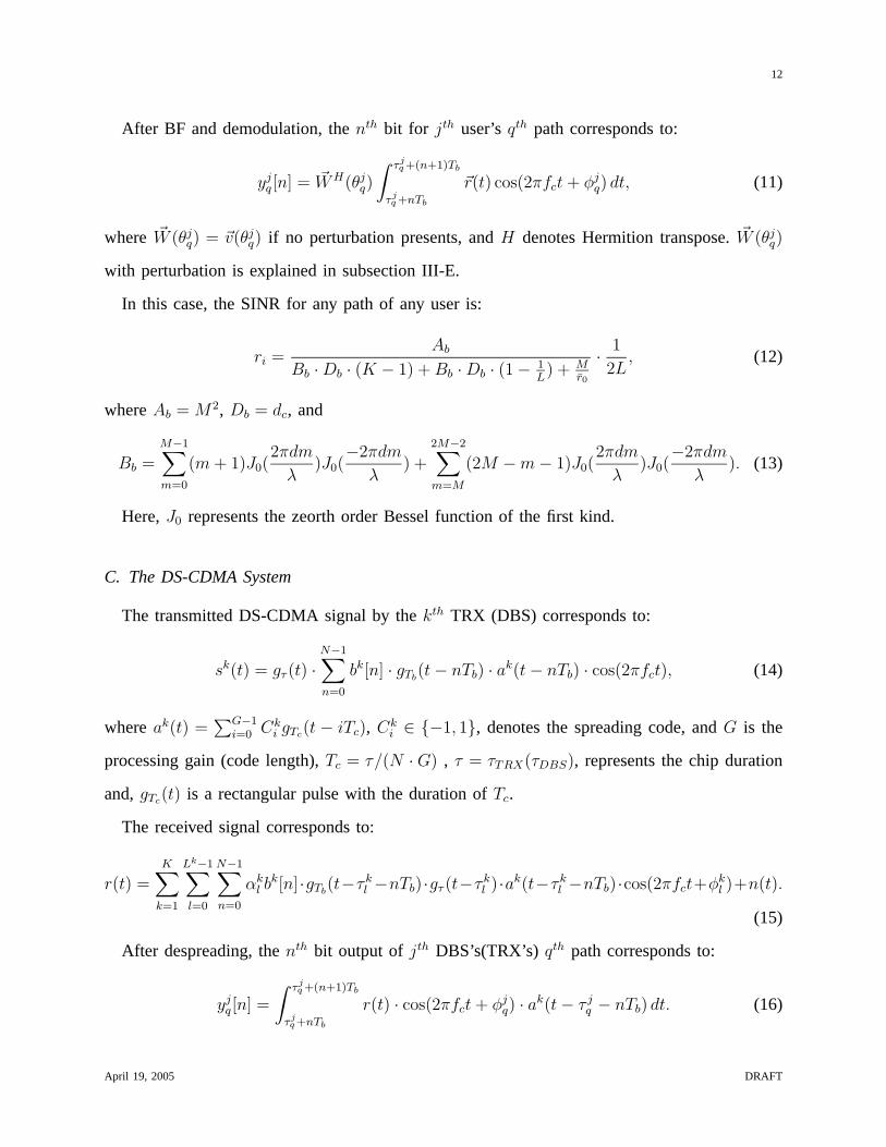
After BF and demodulation, thenth bit for jth user’sqth path corresponds to:
yjq [n] = ~WH(θj
q)
∫ τjq +(n+1)Tb
τjq +nTb
~r(t) cos(2πfct + φjq) dt, (11)
where ~W (θjq) = ~v(θj
q) if no perturbation presents, andH denotes Hermition transpose.~W (θjq)
with perturbation is explained in subsection III-E.
In this case, the SINR for any path of any user is:
ri =Ab
Bb · Db · (K − 1) + Bb · Db · (1 − 1L) + M
r̄0
· 1
2L, (12)
whereAb = M2, Db = dc, and
Bb =M−1∑
m=0
(m + 1)J0(2πdm
λ)J0(
−2πdm
λ) +
2M−2∑
m=M
(2M − m − 1)J0(2πdm
λ)J0(
−2πdm
λ). (13)
Here,J0 represents the zeorth order Bessel function of the first kind.
C. The DS-CDMA System
The transmitted DS-CDMA signal by thekth TRX (DBS) corresponds to:
sk(t) = gτ (t) ·N−1∑
n=0
bk[n] · gTb(t − nTb) · ak(t − nTb) · cos(2πfct), (14)
whereak(t) =∑G−1
i=0 Cki gTc
(t − iTc), Cki ∈ {−1, 1}, denotes the spreading code, andG is the
processing gain (code length),Tc = τ/(N · G) , τ = τTRX(τDBS), represents the chip duration
and,gTc(t) is a rectangular pulse with the duration ofTc.
The received signal corresponds to:
r(t) =K
∑
k=1
Lk−1
∑
l=0
N−1∑
n=0
αkl b
k[n]·gTb(t−τ k
l −nTb)·gτ (t−τ kl )·ak(t−τ k
l −nTb)·cos(2πfct+φkl )+n(t).
(15)
After despreading, thenth bit output of jth DBS’s(TRX’s) qth path corresponds to:
yjq [n] =
∫ τjq +(n+1)Tb
τjq +nTb
r(t) · cos(2πfct + φjq) · ak(t − τ j
q − nTb) dt. (16)
April 19, 2005 DRAFT

13
)(1 tr
][ny jL
][nz j ][2 ny j
][1 ny j
)( trM
)(1 trM −
)(2 tr
RAKE RCVR
RAKE RCVR
RAKE RCVR
RAKE RCVR
BF for path 1
BF for path 2
BF path L
���
C O M B I N E R
ID Detector
Fig. 4. DBS(TRX) receiver structure assuming a frequency selective channel and smart antennas with DS-CDMA
Finally the SINR for any path of any DBS(TRX) is:
ri =Ac
Dc · (K − 1) + Dc · (1 − 1L) + G
r̄0
· 1
2L, (17)
whereAc = G, and
Dc = dc −N2 − 3N + 3
2N2· d2
c . (18)
D. DS-CDMA Merger with SDMA (antenna array with conventional BF)
With the same transmitted signal as in Eq. (14), the receivedsignal at the DBS (TRX) for
the antenna array (see Fig. 4), which is a mixture of signals from different TRXs(DBSs) and
different paths, is given as:
~r(t) =K
∑
k=1
Lk−1
∑
l=0
N−1∑
n=0
αkl ·~V (θk
l )·bk[n]·gTb(t−τ k
l −nTb)·gτ (t−τ kl )·ak(t−τ k
l −nTb)·cos(2πfct+φkl )+~n(t).
(19)
The ith bit output of BF forjth user’sqth path is given as:
yjq [n] = ~WH(θj
q)
∫ τjq +(n+1)Tb
τjq +nTb
~r(t) · cos(2πfct + φjq) · ak(t − τ j
q − nTb) dt. (20)
April 19, 2005 DRAFT

14
Finally, the SINR for any path of any user corresponds to:
ri =Ad
Bd · Dd · (K − 1) + Bd · Dd · (1 − 1L) + MG
r̄0
· 1
2L, (21)
whereAd = M2G, Bd = Bb, andDd = Dc.
E. Perturbation effects
Here, we investigate the effects of perturbation in sensor position, channel phase estimation,
and the effects of mutual coupling between sensors, receiver fluctuation due to temperature and
humidity, quantization effects, different cable length for each sensor, imperfect channel phase
estimation, etc. According to Central Limit Theorem, the summation of these effects leads to
additive zero mean Gaussian random variables along the elements in the array, i.e., the weighting
vector ~W (θkl ) in Eq. (16) and (20) does not match array response vector~V (θk
l ) exactly, but
corresponds to~W (θkl ) = ~V (θk
l )+ ~E , where ~E, called error vector, denotes a column vector that
containsM independent Gaussian random variables with zero mean and varianceσ2ǫ [28].
With this error vector, the peak of the directional beam doesnot point to the desired user
perfectly, but steered away from the desired user. Therefore, the power of the desired user is
reduced. In addition, sidelobe’s power of the directional beam increases; hence, power of IXI(IBI)
increases. As a result, SINR is reduced by perturbation, which is a function ofσ2ǫ .
With perturbations, for standard receiver with antenna arrays, as introduced in Eq. (12), the
SINR for any path of DBS(TRX) corresponds to:
ri =Ae
Be · De · (K−1)2
+ Be · De · (1 − 1L) + M+σ2
ǫ
2r̄0
· 1
L,
whereDe = dc,
Ae = M2 + σ2ǫ
M−1∑
m=0
J0(2 · 2πdm
2), (22)
Be =M−1∑
m=0
(m+1)J0(2πdm
λ)J0(
−2πdm
λ)+
2M−2∑
m=M
(2M−m−1)J0(2πdm
λ)J0(
−2πdm
λ)+σ2
ǫ
M−1∑
m=0
J0(2·2πdm
2).
(23)
April 19, 2005 DRAFT

15
Similarly, for DS-CDMA system with antenna arrays, as introduced in Eq. (21), the SINR for
any path of any user corresponds to:
ri =Af
Bf · Df · (K−1)2
+ Bf · Df · (1 − 1L) + (M+σ2
ǫ )·G2r̄0
· 1
L,
whereDf = De, Bf = Be as introduced in Eq. (23), and
Af = G · (M2 + σ2ǫ
M−1∑
m=0
J0(2 · 2πdm
2)). (24)
F. Path Diversity Combining
Finally, for all of the receivers discussed in parts A-E, we apply Maximal Ratio Combining
(MRC) across the path diversity components [29]:
zj[n] =L
∑
l=1
αjl y
jl [n]. (25)
Therefore, the final instantaneous SINR expression can be written as:
r0 = re · (α21 + α2
2 + · · · + α2L). (26)
In Eq. (26), the parameterre has been defined in Eq. (8), (12), (17), (21), corresponding
to the receivers introduced in previous subsections. The Bit-Error-Rate for all of the discussed
receivers corresponds to:
Pe =
∫
∞
0
Q(√
2r0)f(r0|r̄0) dr0 = 0.5
1 −
√
re
L + re
·L−1∑
l=0
2l
l
· Ll
22l · (L + re)l
. (27)
For frequency-selective channel,L is greater than one. For flat-fading channel,L equals to
one. If all bits are detected correctly, the ID of the desireduser is detected correctly. Therefore,
the probability-of-detection is given as:
Pd = (1 − Pe)N , (28)
April 19, 2005 DRAFT

16
and the probability-of-miss-detection corresponds to:
Pmd = 1 − Pd. (29)
IV. N UMERICAL RESULTSAND ANALYSIS
In this section, we evaluate the POD performance and capacity (in terms of number-of-
TRXs(DBSs)) of WLPS system under multi-TRX, multi-path environment, via simulations and
we compare the results with the theoretical result of Eq. (28). This setup is typically useful for
vehicle collision avoidance applications, where each vehicle is required to cover the front area.
For simulation purposes, we assume:
1) The ID code has6 bits (N = 6);
2) The DS-CDMA code has64 chips (G = 64);
3) Channel delay spread,Tm for a typical street area is27 nsec [30];
4) Carrier frequency =3 GHz, τTRX = 1.2 µs, andτDBS = 24 µs;
5) The antenna array is linear with 4 elements, and element spacing d = λ2
= 0.05 m
(HPBW = 27◦);
6) Four multipaths lead toL = 4 fold path diversity for DS-CDMA system;
7) The TRX distance and angle are uniformly distributed in[ 0 1 ] km and [ 0 π ], respec-
tively;
8) Uniform multi-path intensity profile, i.e., bit energy isdistributed in each path identically;
9) Binary Phase Shift Keying (BPSK) modulation;
10) Perfect power control and DOA, TOA estimation; and,
11) The average Signal-to-Noise Ratio (SNR) introduced in Eq.(8), (12), (17) and (21) is
r̄0 = 20 dB.
12) The error variance, if perturbation presents, equals to0.5, i.e.,σ2ǫ = 0.5. This error variance
means the standard deviation of perturbations is around70% of elements of array response
vector without perturbations.
Based on the assumed setup, then we deduce that TRX signal TOA isuniformly distributed in
[ Td Tmax ], at the DBS receiver. AssumingTd ≪ Tmax, the TRX signal TOA is approximately
April 19, 2005 DRAFT

17
uniformly distributed in[ 0 Tmax ]. In addition, the minimumIRT , IRTmin, is 32 µsec [c.f.,
Eq. (1)]. We select a larger valueIRT = 24 msec in order to reduce the IBI effects. It is worth
mentioning that in the assumptions,τDBS is selected larger thanτTRX , since the IBI effect at
the TRX receiver can be removed via large selection ofIRT . Hence, a smaller bandwidth is
required for the DBS transmitter. With the assumedτDBS andτTRX , the required bandwidth of
a DS-CDMA (standard) transmitter is320MHz (5MHz) for TRX, and16MHz (250KHz) for
DBS, respectively. Hence, DBS required bandwidth is much smaller than the TRX and the WLPS
bandwidth is mainly determined by the TRX transmission bandwidth, as expected. In addition,
using these parameters, the duty cycle for DBS and TRX receivers correspond todc,DBS ≃ 0.1
and dc,TRX ≃ 0.001. Fig. 3 depictspovl as a function of the number of transmitters (TRX or
DBS) for various values of the duty cycle that is a function ofIRT .
As we mentioned earlier, the IBI at the TRX receiver can be considerably reduced by selecting
the IRT as large as possible; however, this selection will not affect IXI at the DBS receiver.
Hence, a TRX receiver can just be implemented by a simple transceiver (or DS-CDMA) system
without employment of BF, while a DBS receiver needs a combination with BF. It should be
mentioned that antenna arrays are required at the DBS receiver for DOA estimation as well. A
small dc,TRX ≃ 0.001 at the TRX receiver leads to a smallpovl, which leads to small IBI and
high POD. In contrast, a largedc,DBS ≃ 0.1 at the DBS receiver leads to a highpovl that results
in high IXI. Both BF and CDMA techniques help to reduce the IXI effects at DBS.
The POD (Pd) of the DBS receiver is depicted in Fig. 5. This figure comparesPd vs. the
number of TRX for a standard transceiver and a DS-CDMA transceiver, with or without antenna
arrays. It shows that in general thePd decreases as the number of TRX increases, which is a
direct result of IXI. While beamforming enhances the POD for astandard receiver, yet it does
not lead to a high POD performance (see the lower two curves).However, BF considerably
enhances the capacity of the DS-CDMA system (see the3rd and 6th curves from the bottom).
Merging DS-CDMA with BF is thus highly promising for enhancingthe Pd performance of
WLPS systems. In Fig. 5 the solid lines represent the theoretical results which have a good
match with the simulations.
April 19, 2005 DRAFT

18
10 20 30 40 50 600
0.1
0.2
0.3
0.4
0.5
0.6
0.7
0.8
0.9
1
Number of TRX
Pro
babi
lity
of D
etec
tion
DS−CDMA+BF, Duty cycle = 0.1, 4 fold diversityStandard RCVR + BF, Duty cycle = 0.0015, 4 foldOnly DS−CDMA, Duty cycle = 0.1, 4 fold diversityOnly Standard RCVR, Duty Cycle = 0.0015, 4 foldStandard RCVR + BF, Dutycycle = 0.1, 1 fold diveOnly Standard RCVR, Duty cycle = 0.1, 1 fold diveTheoretical Results
Fig. 5. Simulation results for DBS receivers, without perturbation.
10 20 30 40 50 600.5
0.55
0.6
0.65
0.7
0.75
0.8
0.85
0.9
0.95
1
Number of DBS
Pro
babi
lity
of D
etec
tion
Only Standard RCVR, Duty cycle = 0.000015, 4 foldDS−CDMA, Duty cycle = 0.001, 4 foldOnly Standard RCVR, Duty Cycle = 0.001, 1 foldTheoretical Results
Fig. 6. Simulation results for TRX receivers, without perturbation.
ThePd results for TRX receiver using standard receiver is shown in Fig. 6. Although simple, a
standard TRX receiver typically achieves goodPd performance. Further improvement is possible
by selecting a largerIRT value, or a smallerτDBS value. Occupying the same bandwidth as
DS-CDMA, a standard receiver should chooseτTRX ( τDBS) to be1/64th of that of a DS-CDMA
system. In this case, the same number of path diversity as theDS-CDMA receiver (i.e., four fold
diversity) is achievable. This corresponds todc,TRX ≃ 0.000015 (dc,DBS ≃ 0.0015), which leads
to a very smallpovl at the DBS (TRX) receiver and very highPd. This fact has been shown in
Fig. 5 (see5th curve from the bottom) and Fig. 6 (see the top curves). The topcurves in Fig.
5 and Fig. 6 have been redrawn in Fig. 7 and 9. In addition, the probability-of-miss-detection
April 19, 2005 DRAFT

19
10 20 30 40 50 600.99
0.991
0.992
0.993
0.994
0.995
0.996
0.997
0.998
0.999
1
Number of TRX
Pro
babi
lity
of D
etec
tion
DS−CDMA+BF, Duty cycle = 0.1, 4 fold diversityStandard RCVR + BF, Duty cycle = 0.0015, 4 foldTheoretical Results
Fig. 7. The top two curves of Fig. 5: Probability ofDetection.
10 20 30 40 50 6010
−5
10−4
10−3
10−2
10−1
Number of TRX
Pro
babi
lity
of M
iss
Det
ectio
n
Standard RCVR + BF, Duty cycle = 0.0015, 4 foldDS−CDMA+BF, Duty cycle = 0.1, 4 fold diversityTheoretical Results
Fig. 8. Probability of miss Detection corresponds to Fig.7.
10 20 30 40 50 600.9985
0.999
0.9995
1
Number of DBS
Pro
babi
lity
of D
etec
tion
DS−CDMA, Duty cycle = 0.001, 4 foldOnly Standard RCVR, Duty cycle = 0.000015, 4 foldTheoretical Results
Fig. 9. The top two curves of Fig. 6: Probability ofDetection.
10 20 30 40 50 6010
−5
10−4
10−3
10−2
Number of DBS
Pro
babi
lity
of M
iss
Det
ectio
n
Only Standard RCVR, Duty cycle = 0.000015, 4 foldDS−CDMA, Duty cycle = 0.001, 4 foldTheoretical Results
Fig. 10. Probability of miss Detection corresponds toFig. 9.
[defined in Eq. (29)] corresponding to the curves in Fig. 7 and9 have been sketched in Fig. 8
and 10, respectively.
Fig. 7 and 8 show that, at the DBS receiver with similar bandwidths, DS-CDMA receivers
outperforms standard receivers. When high number of TRXs are available, (e.g., Number of
TRX=60), Pd of standard system is approximately99%, while Pd of DS-CDMA system is
approximately99.8%. Hence,Pd of DS-CDMA system satisfies most tracking purposes, which
is due to a combination of path diversity and orthogonality achieved via these systems.
Fig. 10 shows that, at the TRX receiver with similar bandwidths, a DS-CDMA system
outperforms standard system too. Because of the large selection of IRT helps reduce IBI, TRX
receiver with antenna array performance is even better thanDBS receiver with antenna array in
April 19, 2005 DRAFT

20
10 20 30 40 50 6010
−5
10−4
10−3
10−2
10−1
Number of TRX
Pro
babi
lity
of M
iss
Det
ectio
n
Standard RCVR + BF, σe2=0.5
Standard RCVR + BF, σe2=0
DS−CDMA + BF, σe2=0.5
DS−CDMA + BF, σe2=0
Theoretical Results
Fig. 11. DBS performance with perturbations vs. Number of Users.
similar environments. When high number of TRXs are available,(e.g., Number of TRX=60), Pd
of standard system is approximately99.9%, while Pd of DS-CDMA system is approximately
99.99%. Note that the TRX receiver performance can also be improved via larger selection of
IRT (such as0.24 sec). Due to simplicity, a standard receiver system is recommended for TRX
receiver.
Fig. 11 shows the capacity of the system, i.e., the probability-of-miss-detection as a function
of the number of TRX, under perturbations. This figure shows the system capacity decreases as
the error variance equals to0.5, and setting the probability-of-miss-detection threshold at 0.1%,
the system capacity is reduced by20% for DS-CDMA system, and30% for standard systems.
V. CONCLUSIONS
This paper presents a novel WLPS system. With a DBS/TRX structure and a novel signal-
ing technique, WLPS would have various applications in road safety (vehicle collision avoid-
ance), multirobot control, defense, law enforcement, and security. We studied and compared the
probability-of-detection (POD) performance and the capacity of DBS and TRX with both DS-
CDMA and standard systems with and without beamforming (BF) for a special setup suitable
for road safety applications. The study shows that with similar bandwidth both DS-CDMA
and standard systems with BF ensures high POD performance andcapacity while DS-CDMA
April 19, 2005 DRAFT

21
technique leads to a better performance comparing to standard receivers. We also investigated the
perturbation effects in DBS antenna array weights. Perturbation reduces the asymptotic system
POD performance and capacity. Future studies will focus on the development of unique DOA
estimation for WLPS as well as adaptive BF techniques at the DBS receiver for high scattering
environments.
REFERENCES
[1] S. A. Zekavat, “Mobile Base Station (MBS) wireless with applications in vehicle early warning systems,” inProceedings
the University of Texas at Austin 2003 Wireless Networking Symposium, Oct. 2003.
[2] S. A. Zekavat, H. Tong, and J. Tan, “A Novel Wireless Local Positioning System for Airport (Indoor) Security,” in
Proceedings of The International Society for Optical Engineering (SPIE 2004).
[3] H. Tong and S. A. Zekavat, “LCMV Beamforming for a Novel Wireless Local Positioning System: A Stationarity Analysis,”
in Proceedings of The International Society for Optical Engineering (SPIE 2005), Mar. 2005.
[4] L. V. Grant, “An overview of the Federal Radionavigation Plan,” inIEEE 21st Annual conference on Electronics and
Aerospace Conference, (EASCON’88), Nov. 1988, pp. 173–177.
[5] I. A. Getting, “Perspective/Navigation-The Global Positioning System,” IEEE Spectrum, vol. 30, no. 12, pp. 36–38, Dec.
1993.
[6] J. Werb and C. Lanzl, “Designing a positioning system for finding things and people indoors,”IEEE Spectrum, vol. 35,
no. 9, pp. 71–78, Sept. 1998.
[7] M. E. Bernard, “The Global Positioning System,”IEE Review, vol. 38, pp. 99–102, Mar. 1992.
[8] M. Vossiek, L. Wiebking, P. Gulden, J. Wieghardt, and C. Hoffmann, “Wireless local positioning - Concepts, solutions,
applications,” inRadio and Wireless Conference, RAWCON ’03. Proceedings, Aug. 2003, pp. 219–224.
[9] M. I. Skolnik, Introduction to Radar Systems. Mc-Graw Hill Co, 1981.
[10] M. Sekine, T. Senoo, I. Morita, and H. Endo, “Design method foran automotive laser radar system and future prospects
for laser radar,” inIntelligent Vehicles Symposium ’92., 1992, pp. 120–125.
[11] R. Hermann, M. Marc-Michel, K. Michael, and L. Urs, “Research activities in automotive Radar,” inMSMW’01 Symp.,
2001.
[12] K. Saneyoshi, “Drive assist system using stereo image recognition,” in IEEE Intelligent Vehicle Symp., 1996, pp. 230–235.
[13] T. Williamson and N. A. Spencer, “Development and operation of the Traffic Alert and Collision Avoidance System
(TCAS),” IEEE Control Systems Magazine, vol. 77, no. 11, pp. 1735–1744, Nov. 1989.
[14] S. Kahne and I. Frolow, “Air traffic management: evolution with technology,” IEEE Proceedings, vol. 16, no. 4, pp. 12–21,
Aug. 1996.
[15] R. M. Trim, “Mode S: An introduction and overview [secondary surveillance radar],” Journal of Electronics and
Communication Engineering, vol. 2, no. 2, pp. 53–59, Apr. 1990.
April 19, 2005 DRAFT
22
[16] S. Ractliffe, “Air traffic control and mid-air collisions,”Journal of Electronics and Communication Engineering, vol. 2,
no. 5, pp. 202 – 208, Oct. 1990.
[17] M. Cedervall, “Mobile positioning for third generation WCDMA systems,” in IEEE 1998 International Conference on
Universal Personal Communications, (ICUPC ’98), Oct. 1998.
[18] E. Hepsaydir, “Analysis of mobile positioning measurements in CDMAcellular networks,” in1999 IEEE Radio and
Wireless Conference, (RAWCON ’99), Aug. 1999.
[19] S. Kikuchi, A. Sano, H. Tsuji, and R. Miura, “A novel approach tomobile-terminal positioning using single array antenna
in urban environments,” in2003 IEEE 58th Vehicular Technology Conference, VTC 2003-Fall, vol. 2, Oct. 2003.
[20] L. M. Ni, Y. Liu, Y. C. Lau, and A. P. Patil, “LANDMARC: indoor location sensing using active RFID,” inProceedings
of the First IEEE International Conference on Pervasive Computing and Communications, (PerCom ’2003), Mar. 2003.
[21] R. Singh, M. Guainazzo, and C. S. Regazzoni, “Location determination using WLAN in conjuction with GPS network
(global positioning system),” in2004 IEEE 59th Vehicular Technology Conference, VTC 2004-Spring, May 2004.
[22] J. Li, J. Jannotti, S. J. Douglas, D. Couto, D. R. Karger, and R. Morris, “A Scalable Location Service for Geographic Ad
Hoc Routing,” inACM Mobicom 2000, Boston, MA, 2000, pp. 120–130.
[23] H. Gharavi and K. Ban, “Multihop sensor network design for wide-band communications,”Proceedings of the IEEE,
vol. 91, no. 8, pp. 1221–1234, Aug 2003.
[24] J. Yang and A. L. Swindlehurst, “The effects of array calibrationerrors on DF-Based signal copy performance,”IEEE
Transactions on Signal Processing, vol. 43, no. 11, pp. 2724–2732, Nov. 1995.
[25] L. C. Godara, “Application of antenna arrays to mobile communications. II. Beam-forming and direction-of-arrival
considerations,”Proceedings of the IEEE, vol. 85, no. 8, pp. 1195–1245, Aug 1997.
[26] M. Wax and Y. Anu, “Performance analysis of the minimum variance beamformer in the presence of steering vector
errors,” IEEE Transactions on Signal Processing, vol. 44, no. 4, pp. 938–947, Apr 1997.
[27] S. A. Zekavat, “A novel application for wireless communications in vehicle early warning,” inConsumer Communications
and Networking Conference, Jan 2004, pp. 715–717.
[28] A. M. Rao and D. L. Jones, “Efficient quadratic detection in perturbed arrays via Fourier transform techniques,”IEEE
Transactions on Signal Processing, vol. 49, no. 7, pp. 1269 – 1281, July 2001.
[29] A. Shah and A. Haimovich, “Performance analysis of maximal ratio combining and comparison with optimum combining
for mobile radio communications with cochannel interference,”IEEE Transactions on Vehicular Technology, vol. 49, no. 4,
pp. 1454–1463, Jul 2000.
[30] A. A. Arowojolu, A. M. D. Turkman, and J. D. Parsons, “Time dispersion in urban microcellular enviroments,” inIEEE
44th Vehicular Technical Conference, vol. 1, jun 1994, pp. 150–154.
April 19, 2005 DRAFT