Embed Size (px)
Citation preview

Preface, Contents
Introduction 1
Functionality 2
Commissioning 3
Operation 4
TP 170A Screen Objects 5
TP 170B and OP 170B Screen Objects 6
TP 170B and OP 170B Recipes 7
System Settings 8
Installation 9
Dimensions 10
TP 170B and OP 170BMemory Cards 11
Maintenance/Upkeep 12
Operating System Update 13
Appendices
A
D
Glossary, Index
Release 12/01A5E00136801
Order No.: 6AV6591-1DC11-2AB0
Touch Panel TP 170A, TP 170BOperator Panel OP 170B
Equipment Manual
SIMATIC HMI

!Danger
indicates an imminently hazardous situation which, if not avoided, will result in death or serious injury.
!Warningindicates a potentially hazardous situation which, if not avoided, could result in death or serious injury.
!Cautionused with the safety alert symbol indicates a potentially hazardous situation which, if not avoided, may result inminor or moderate injury.
Cautionused without the safety alert symbol indicates a potentially hazardous situation which, if not avoided, mayresult in property damage.
Noticeindicates that unwanted events or status can occur if the relevant information is not observed.
Notedraws your attention to particularly important information on the product, handling the product, or to a particularpart of the documentation.
Qualified Personnel
Equipment may be commissioned and operated only by qualified personnel. Qualified personnel within themeaning of the safety notices in this manual are persons who are authorized to commission, ground and iden-tify equipment, systems and circuits in accordance with safety engeneering standards.
Correct Usage
Please note the following:
!WarningThe device may only be used for the application cases specified in the catalog and the technical descriptionand may only be used in combination with third-party equipment and components recommended or approvedby Siemens.
Startup must not take place until it is established that the machine which is to accommodate this component isconforms with the guideline 98/37 EC.
Appropriate transport, and appropriate storage, installation and assembly, as well as careful operation andmaintenance, are required to ensure that the product operates perfectly and safely.
Safety GuidelinesThis manual contains notices which you should observe to ensure your own personal safety, as well as toprotect the product and connected equipment. These notices are marked as follows according to the levelof danger:

Trademarks
The registered trademarks of the Siemens AG can be found in the preface. The remaining trademarks in thispublication may be trademarks, whose use by third parties for their own purposes could violate the rights of theowner.
Impressum
Editor and Publisher: A&D PT1 D1
We have checked the content of this publication for compliance with thedescribed hardware and software. However, discrepancies cannot be exclu-ded, with the result that we cannot guarantee total compliance. The informa-tion in this publication is, however, checked regularly, and any necessarycorrections are included in the following editions. We welcome any suggesti-ons for improvement.
Exclusion of LiabilityCopyright Siemens AG 2001 All rights reserved
The transmission and reproduction of this documentation and the exploitationand communication of its contents are not permitted without expressauthority. Offenders will be liable for compensation for damage. All rightsreserved, especially in the case of the granting of a patent or registration of autility model or design
Siemens AGAutomation & DrivesSIMATIC Human Machine InterfacePostfach 4848, D-90327 Nürnberg
� Siemens AG 2001Technical data subject to change.
Siemens Aktiengesellschaft Order no. 6AV6591-1DC11-2AB0

For your notes

iTouch Panel TP 170A, TP 170B, Operator Panel OP 170B Equipment Manual6AV6591-1DC11-2AB0
Preface
This manual
The TP 170A, TP 170B, OP 170B equipment manual is part of the SIMATIC HMIdocumentation. It provides operation, installation, configuration and maintenancepersonnel with information concerning installation, functionality, operation andtechnical design of the SIMATIC operating units TP 170A, TP 170B and OP 170B.
Organization of the manual
The manual is organized into the following chapters:
Chapter Contents
1 - 2 Overview of the features and functional scope of the unit
3 - 6 Commissioning and operation
7 TP 170B and OP 170B recipes
8 System settings
9 - 12 Mechanical and electrical installation, unit description, retrofitting ofoptions as well as maintenance and upkeep.
13 Information on updating the operating system
Appendix � Technical Data
� Interface Assignments
� HMI System Messages
� ESD Guidelines

Preface Release 12/01
iiTouch Panel TP 170A, TP 170B, Operator Panel OP 170B Equipment Manual
6AV6591-1DC11-2AB0
Conventions
The following conventions are used throughout this manual:
Motor off Text in the operating unit display is presented in thistypewriter font.
Tag Symbolic names representing tag values on the screen arepresented in this italic typewriter font.
Screens Functions available for selection are presented in this italicfont.
ESC The names of keys and buttons are displayed in a differentfont.
History
The various releases of this manual correspond to the following versions of theProTool CS configuration software:
Edition Comment ProTool Version
12/99 First release of the TP 170A equipmentmanual
From V5.2
07/00 Extensions to the TP 170B and OP 170Bdevices
From V5.2 + SP2
12/01 New ProTool software, more screen objects From V 6.0

PrefaceRelease 12/01
iiiTouch Panel TP 170A, TP 170B, Operator Panel OP 170B Equipment Manual6AV6591-1DC11-2AB0
Trademarks
The following names are registered trademarks of the Siemens AG:
� HMI
� MP 270
� MP 270B
� MP 370
� ProAgent
� ProTool
� ProTool/Lite
� ProTool/Pro
� SIMATIC
� SIMATIC HMI
� SIMATIC Multi Panel
� SIMATIC Multifunctional Platform
� WinCC
� WinCC Add-on

Preface Release 12/01
ivTouch Panel TP 170A, TP 170B, Operator Panel OP 170B Equipment Manual
6AV6591-1DC11-2AB0
Other support
In case of technical queries, please contact the Siemens representatives in thesubsidiaries and branches responsible for your area.
Customer and Technical Support
Available round the clock, worldwide:
Johnson City
Nuremberg
Singapore
SIMATIC Hotline
Worldwide (Nuremberg)
Technical Support
(FreeContact)
Local time: Mon.-Fri. 7:00 to 17:00
Telephone: +49 (180) 5050-222
Fax: +49 (180) 5050-223
E-Mail: [email protected]
GMT: +1:00
Worldwide (Nuremberg)
Technical Support
(fee-based, only with SIMATICCard)Local time: Mon.-Fri. 0:00 to 24:00
Telephone: +49 (911) 895-7777
Fax: +49 (911) 895-7001
GMT: +01:00
Europe / Africa (Nuremberg)
Authorization
Local time: Mon.-Fri. 7:00 to 17:00
Telephone: +49 (911) 895-7200
Fax: +49 (911) 895-7201
E-Mail: [email protected]
GMT: +1:00
America (Johnson City)
Technical Support andAuthorizationLocal time: Mon.-Fri. 8:00 to 19:00
Telephone: +1 423 461-2522
Fax: +1 423 461-2289
E-Mail: [email protected]
GMT: –5:00
Asia / Australia (Singapore)
Technical Support andAuthorizationLocal time: Mon.-Fri. 8:30 to 17:30
Telephone: +65 740-7000
Fax: +65 740-7001
E-Mail: [email protected]
GMT: +8:00
The languages spoken by the SIMATIC Hotlines are generally German and English, the Authorization Hotline is alsoprovided in French, Italian and Spanish.

PrefaceRelease 12/01
vTouch Panel TP 170A, TP 170B, Operator Panel OP 170B Equipment Manual6AV6591-1DC11-2AB0
SIMATIC Customer Support Online Services
The SIMATIC Customer Support provides you with additional information aboutSIMATIC products through online services:
� General current information can be obtained
– in the Internet under http://www.ad.siemens.de/simatic
� Current product information and downloads which you may find useful areavailable:
– in the Internet under http://www.ad.siemens.de/simatic–cs and
– via the Bulletin Board System (BBS) in Nuremberg (SIMATIC CustomerSupport Mailbox) under the number +49 (911) 895-7100
To dial the mailbox, use a modem with a capacity up to V.34 (28.8 kBaud)whose parameters are set as follows: – 8, N, 1, ANSI, or – dial via ISDN (x.75, 64 kBit).
� Your contact partner for Automation & Drives can be found in the contactpartner database
– in the Internet underhttp://www3.ad.siemens.de/partner/search.asp
Abbreviations
The abbreviations used in this manual have the following meaning:
AG (PLC) Programmable Logic Controller
ANSI American National Standards Institute
AS 511 Protocol of the PU interface to SIMATIC S5
ASCII American Standard Code for Information Interchange
EM Event Message
CCFL Cold Cathode Fluorescence Lamp
CF Compact Flash
CPU Central Processing Unit
CSV Comma Separated Values
DP Decentralized Periphery
DRAM Dynamic Random Access Memory
DSN Data Source Name
ESD Electrostatically Sensitive Device
EMC Electromagnetic Compatibility
HMI Human Machine Interface
IF Interface

Preface Release 12/01
viTouch Panel TP 170A, TP 170B, Operator Panel OP 170B Equipment Manual
6AV6591-1DC11-2AB0
LCD Liquid Crystal Display
LED Light Emitting Diode
MP Multi Panel
MPI Multipoint Interface (SIMATIC S7)
OP Operator Panel
PC Personal Computer
PCL Printer Control Language
PU Programming Unit
PPI Point to Point Interface (SIMATIC S7)
RAM Random Access Memory
SELV Safety Extra Low Voltage
AM Alarm Message
PLC Programmable Logic Controller
SRAM Static Random Access Memory
STN Super Twisted Nematic
TCP/IP Transmission Control Protocol/Internet Protocol
TFT Thin Film Transistor
TTL Transistor-Transistor Logic
TP Touch Panel
UPS Uninterruptible Power Supply (USV)
A list of all the specialist terms together with their explanations is provided in theGlossary at the end of this guide.

PrefaceRelease 12/01
viiTouch Panel TP 170A, TP 170B, Operator Panel OP 170B Equipment Manual6AV6591-1DC11-2AB0
SIMATIC HMI Documentation
Target groups
This manual is part of the SIMATIC HMI Documentation. The documentation isaimed at the following target groups:
� Beginners
� Users
� Configuration planners
� Programmers
� Service engineers
Documentation structure
The SIMATIC HMI Documentation includes the following components:
� User guides for
– configuration software
– runtime software
– communication between PLC and operating unit
� Equipment manuals for the following operating units:
– SIMATIC PC
– MP (Multi Panel)
– OP (Operator Panel)
– TP (Touch Panel)
– TD (Text Display)
– PP (Pushbutton Panel)
� Online help for the configuration software
� Installation guides
� Quick reference manuals

Preface Release 12/01
viiiTouch Panel TP 170A, TP 170B, Operator Panel OP 170B Equipment Manual
6AV6591-1DC11-2AB0
The following table provides an overview of the SIMATIC HMI Documentationhelpful for this manual.
Documentation Target group Contents
Getting Started
Quick Reference Manual
Beginners These documents provide a step by step guide to theconfiguration of
� a screen with various objects,
� changing screens,
� a message.
This documentation is available for
� text-based displays,
� graphics displays,
� touch panels,
� Windows-based systems.
ProToolConfiguringWindows-based Systems
User’s Guide
Configurationplanners
Provides the following information for working with theconfiguration software:
� principles of the configuration,
� detailed description of objects and functions whichcan be configured,
� examples.
ProTool
Online Help
Configurationplanners
Contains the following information while working withProTool on the configuration computer:
� context-sensitive help,
� detailed instructions and examples,
� detailed information,
� all information from the user guides.
Communication forWindows-based Systems
User’s Guide
Programmers Provides information on connecting Windows-basedsystems to the following PLCs:
� SIMATIC S5
� SIMATIC S7
� SIMATIC 505
� SIMATIC WinAC
� SIMOTION
� PLCs from other manufacturors
This documentation describes
� the configuration and parameters necessary toconnect the units to the PLC and network,
� the user data areas which serve for data exchangebetween the operating unit and PLC.

ixTouch Panel TP 170A, TP 170B, Operator Panel OP 170B Equipment Manual6AV6591-1DC11-2AB0
Contents
1 Introduction 1-1 . . . . . . . . . . . . . . . . . . . . . . . . . . . . . . . . . . . . . . . . . . . . . . . . . . . . . . . . . . . .
2 Functionality 2-1 . . . . . . . . . . . . . . . . . . . . . . . . . . . . . . . . . . . . . . . . . . . . . . . . . . . . . . . . . . .
3 Commissioning 3-1 . . . . . . . . . . . . . . . . . . . . . . . . . . . . . . . . . . . . . . . . . . . . . . . . . . . . . . . .
3.1 Initial Startup 3-3 . . . . . . . . . . . . . . . . . . . . . . . . . . . . . . . . . . . . . . . . . . . . . . . . . . .
3.2 Recommissioning 3-4 . . . . . . . . . . . . . . . . . . . . . . . . . . . . . . . . . . . . . . . . . . . . . . . 3.2.1 Start downloading manually 3-4 . . . . . . . . . . . . . . . . . . . . . . . . . . . . . . . . . . . . . . 3.2.2 Start downloading automatically during normal operation 3-5 . . . . . . . . . . . . .
3.3 Operating Unit Start Menu 3-6 . . . . . . . . . . . . . . . . . . . . . . . . . . . . . . . . . . . . . . . .
3.4 Options for Download Mode 3-7 . . . . . . . . . . . . . . . . . . . . . . . . . . . . . . . . . . . . . .
3.5 Test the Configuration 3-11 . . . . . . . . . . . . . . . . . . . . . . . . . . . . . . . . . . . . . . . . . . .
3.6 Uploading (TP 170B and OP 170B) 3-13 . . . . . . . . . . . . . . . . . . . . . . . . . . . . . . . .
3.7 ProSave Service Tool 3-15 . . . . . . . . . . . . . . . . . . . . . . . . . . . . . . . . . . . . . . . . . . . .
3.8 Backup/Restore the Internal Flash Memory 3-16 . . . . . . . . . . . . . . . . . . . . . . . . . 3.8.1 Backup/Restore on memory card (TP 170B and OP 170B) 3-17 . . . . . . . . . . . . 3.8.2 Backup/Restore using ProSave 3-18 . . . . . . . . . . . . . . . . . . . . . . . . . . . . . . . . . . .
3.9 License Transfer (Authorization) using ProSave (TP 170B and OP 170B) 3-21
3.10 Loading Applications with ProSave (TP 170B and OP 170B) 3-23 . . . . . . . . . .
4 Operation 4-1 . . . . . . . . . . . . . . . . . . . . . . . . . . . . . . . . . . . . . . . . . . . . . . . . . . . . . . . . . . . . . .
4.1 Operating the TP 170A and TP 170B Touch Panels 4-1 . . . . . . . . . . . . . . . . . . 4.1.1 Operating touch elements 4-1 . . . . . . . . . . . . . . . . . . . . . . . . . . . . . . . . . . . . . . . . 4.1.2 Enter numeric values 4-3 . . . . . . . . . . . . . . . . . . . . . . . . . . . . . . . . . . . . . . . . . . . . 4.1.3 Enter alphanumeric values 4-5 . . . . . . . . . . . . . . . . . . . . . . . . . . . . . . . . . . . . . . . 4.1.4 Calling in help text on the TP 170B 4-6 . . . . . . . . . . . . . . . . . . . . . . . . . . . . . . . .
4.2 Operating the OP 170B Keyboard Unit 4-8 . . . . . . . . . . . . . . . . . . . . . . . . . . . . . 4.2.1 Integrated keyboard 4-8 . . . . . . . . . . . . . . . . . . . . . . . . . . . . . . . . . . . . . . . . . . . . . 4.2.2 Function keys/Softkeys 4-9 . . . . . . . . . . . . . . . . . . . . . . . . . . . . . . . . . . . . . . . . . . 4.2.3 System keys 4-10 . . . . . . . . . . . . . . . . . . . . . . . . . . . . . . . . . . . . . . . . . . . . . . . . . . . . 4.2.4 Key combinations 4-12 . . . . . . . . . . . . . . . . . . . . . . . . . . . . . . . . . . . . . . . . . . . . . . . 4.2.5 Entering values 4-14 . . . . . . . . . . . . . . . . . . . . . . . . . . . . . . . . . . . . . . . . . . . . . . . . .
4.3 Calling in Help Text on the OP 170B 4-15 . . . . . . . . . . . . . . . . . . . . . . . . . . . . . . .
5 TP 170A Screen Objects 5-1 . . . . . . . . . . . . . . . . . . . . . . . . . . . . . . . . . . . . . . . . . . . . . . . .
5.1 Operating Screens 5-1 . . . . . . . . . . . . . . . . . . . . . . . . . . . . . . . . . . . . . . . . . . . . . .
5.2 Logging On and Off 5-2 . . . . . . . . . . . . . . . . . . . . . . . . . . . . . . . . . . . . . . . . . . . . . .

Contents Release 12/01
xTouch Panel TP 170A, TP 170B, Operator Panel OP 170B Equipment Manual
6AV6591-1DC11-2AB0
5.3 Overview of Screen Objects 5-4 . . . . . . . . . . . . . . . . . . . . . . . . . . . . . . . . . . . . . .
5.4 Input Field 5-5 . . . . . . . . . . . . . . . . . . . . . . . . . . . . . . . . . . . . . . . . . . . . . . . . . . . . . .
5.5 Status Button 5-7 . . . . . . . . . . . . . . . . . . . . . . . . . . . . . . . . . . . . . . . . . . . . . . . . . . .
5.6 Bar Graphs 5-9 . . . . . . . . . . . . . . . . . . . . . . . . . . . . . . . . . . . . . . . . . . . . . . . . . . . . .
5.7 Messages 5-10 . . . . . . . . . . . . . . . . . . . . . . . . . . . . . . . . . . . . . . . . . . . . . . . . . . . . . .
6 TP 170B and OP 170B Screen Objects 6-1 . . . . . . . . . . . . . . . . . . . . . . . . . . . . . . . . . . . .
6.1 Operating Screens 6-1 . . . . . . . . . . . . . . . . . . . . . . . . . . . . . . . . . . . . . . . . . . . . . .
6.2 Logging On and Off 6-4 . . . . . . . . . . . . . . . . . . . . . . . . . . . . . . . . . . . . . . . . . . . . . .
6.3 Overview of Screen Objects 6-5 . . . . . . . . . . . . . . . . . . . . . . . . . . . . . . . . . . . . . .
6.4 Input Field 6-8 . . . . . . . . . . . . . . . . . . . . . . . . . . . . . . . . . . . . . . . . . . . . . . . . . . . . . .
6.5 Selection Field 6-10 . . . . . . . . . . . . . . . . . . . . . . . . . . . . . . . . . . . . . . . . . . . . . . . . .
6.6 Date/Time 6-12 . . . . . . . . . . . . . . . . . . . . . . . . . . . . . . . . . . . . . . . . . . . . . . . . . . . . . .
6.7 Graphic Box 6-14 . . . . . . . . . . . . . . . . . . . . . . . . . . . . . . . . . . . . . . . . . . . . . . . . . . . .
6.8 Buttons 6-15 . . . . . . . . . . . . . . . . . . . . . . . . . . . . . . . . . . . . . . . . . . . . . . . . . . . . . . . .
6.9 Status Button 6-17 . . . . . . . . . . . . . . . . . . . . . . . . . . . . . . . . . . . . . . . . . . . . . . . . . . .
6.10 Switch 6-19 . . . . . . . . . . . . . . . . . . . . . . . . . . . . . . . . . . . . . . . . . . . . . . . . . . . . . . . . .
6.11 Messages 6-20 . . . . . . . . . . . . . . . . . . . . . . . . . . . . . . . . . . . . . . . . . . . . . . . . . . . . . . 6.11.1 ALARM_S 6-22 . . . . . . . . . . . . . . . . . . . . . . . . . . . . . . . . . . . . . . . . . . . . . . . . . . . . . . 6.11.2 Message line 6-24 . . . . . . . . . . . . . . . . . . . . . . . . . . . . . . . . . . . . . . . . . . . . . . . . . . . 6.11.3 Message window 6-24 . . . . . . . . . . . . . . . . . . . . . . . . . . . . . . . . . . . . . . . . . . . . . . . . 6.11.4 Message page 6-26 . . . . . . . . . . . . . . . . . . . . . . . . . . . . . . . . . . . . . . . . . . . . . . . . . . 6.11.5 Message buffer 6-27 . . . . . . . . . . . . . . . . . . . . . . . . . . . . . . . . . . . . . . . . . . . . . . . . . 6.11.6 Message display 6-28 . . . . . . . . . . . . . . . . . . . . . . . . . . . . . . . . . . . . . . . . . . . . . . . . 6.11.7 Single message display 6-30 . . . . . . . . . . . . . . . . . . . . . . . . . . . . . . . . . . . . . . . . . .
6.12 Bar Graphs 6-31 . . . . . . . . . . . . . . . . . . . . . . . . . . . . . . . . . . . . . . . . . . . . . . . . . . . . .
6.13 Trend View 6-32 . . . . . . . . . . . . . . . . . . . . . . . . . . . . . . . . . . . . . . . . . . . . . . . . . . . . .
6.14 Password List 6-35 . . . . . . . . . . . . . . . . . . . . . . . . . . . . . . . . . . . . . . . . . . . . . . . . . . 6.14.1 Password management 6-36 . . . . . . . . . . . . . . . . . . . . . . . . . . . . . . . . . . . . . . . . . . 6.14.2 Export/Import password list 6-37 . . . . . . . . . . . . . . . . . . . . . . . . . . . . . . . . . . . . . . .
7 TP 170B and OP 170B Recipes 7-1 . . . . . . . . . . . . . . . . . . . . . . . . . . . . . . . . . . . . . . . . . .
7.1 Overview 7-1 . . . . . . . . . . . . . . . . . . . . . . . . . . . . . . . . . . . . . . . . . . . . . . . . . . . . . . .
7.2 Use of Recipes 7-3 . . . . . . . . . . . . . . . . . . . . . . . . . . . . . . . . . . . . . . . . . . . . . . . . . 7.2.1 Data flow for recipes 7-3 . . . . . . . . . . . . . . . . . . . . . . . . . . . . . . . . . . . . . . . . . . . . . 7.2.2 Application examples 7-4 . . . . . . . . . . . . . . . . . . . . . . . . . . . . . . . . . . . . . . . . . . . .
7.3 Recipe Configuration 7-6 . . . . . . . . . . . . . . . . . . . . . . . . . . . . . . . . . . . . . . . . . . . .
7.4 Editing Data Records 7-9 . . . . . . . . . . . . . . . . . . . . . . . . . . . . . . . . . . . . . . . . . . . . 7.4.1 Recipe view 7-10 . . . . . . . . . . . . . . . . . . . . . . . . . . . . . . . . . . . . . . . . . . . . . . . . . . . . 7.4.2 Recipe screens 7-18 . . . . . . . . . . . . . . . . . . . . . . . . . . . . . . . . . . . . . . . . . . . . . . . . . 7.4.3 Functions and PLC jobs 7-21 . . . . . . . . . . . . . . . . . . . . . . . . . . . . . . . . . . . . . . . . . . 7.4.4 Import/Export data records 7-22 . . . . . . . . . . . . . . . . . . . . . . . . . . . . . . . . . . . . . . . 7.4.5 Reaction on changing the recipe structure 7-26 . . . . . . . . . . . . . . . . . . . . . . . . . .

ContentsRelease 12/01
xiTouch Panel TP 170A, TP 170B, Operator Panel OP 170B Equipment Manual6AV6591-1DC11-2AB0
8 System Settings 8-1 . . . . . . . . . . . . . . . . . . . . . . . . . . . . . . . . . . . . . . . . . . . . . . . . . . . . . . . .
8.1 TP 170A Settings 8-2 . . . . . . . . . . . . . . . . . . . . . . . . . . . . . . . . . . . . . . . . . . . . . . . 8.1.1 Set operating mode 8-2 . . . . . . . . . . . . . . . . . . . . . . . . . . . . . . . . . . . . . . . . . . . . . . 8.1.2 Change language 8-2 . . . . . . . . . . . . . . . . . . . . . . . . . . . . . . . . . . . . . . . . . . . . . . . 8.1.3 Set date/time 8-2 . . . . . . . . . . . . . . . . . . . . . . . . . . . . . . . . . . . . . . . . . . . . . . . . . . . 8.1.4 Screen settings 8-3 . . . . . . . . . . . . . . . . . . . . . . . . . . . . . . . . . . . . . . . . . . . . . . . . . 8.1.5 Set screen saver response time 8-4 . . . . . . . . . . . . . . . . . . . . . . . . . . . . . . . . . . .
8.2 Settings for TP 170B and OP 170B 8-5 . . . . . . . . . . . . . . . . . . . . . . . . . . . . . . . . 8.2.1 Set language 8-5 . . . . . . . . . . . . . . . . . . . . . . . . . . . . . . . . . . . . . . . . . . . . . . . . . . . 8.2.2 Setting an operating mode 8-6 . . . . . . . . . . . . . . . . . . . . . . . . . . . . . . . . . . . . . . . . 8.2.3 Settings in Windows CE Control Panel 8-7 . . . . . . . . . . . . . . . . . . . . . . . . . . . . . 8.2.4 Device properties 8-8 . . . . . . . . . . . . . . . . . . . . . . . . . . . . . . . . . . . . . . . . . . . . . . . . 8.2.5 Screensaver 8-12 . . . . . . . . . . . . . . . . . . . . . . . . . . . . . . . . . . . . . . . . . . . . . . . . . . . . 8.2.6 Screen keyboard 8-12 . . . . . . . . . . . . . . . . . . . . . . . . . . . . . . . . . . . . . . . . . . . . . . . . 8.2.7 Regional settings 8-13 . . . . . . . . . . . . . . . . . . . . . . . . . . . . . . . . . . . . . . . . . . . . . . . . 8.2.8 Set printer 8-13 . . . . . . . . . . . . . . . . . . . . . . . . . . . . . . . . . . . . . . . . . . . . . . . . . . . . . .
9 Installation 9-1 . . . . . . . . . . . . . . . . . . . . . . . . . . . . . . . . . . . . . . . . . . . . . . . . . . . . . . . . . . . . .
9.1 Mechanical Installation 9-2 . . . . . . . . . . . . . . . . . . . . . . . . . . . . . . . . . . . . . . . . . . . 9.1.1 Installing the TP 170A or TP 170B 9-3 . . . . . . . . . . . . . . . . . . . . . . . . . . . . . . . . . 9.1.2 Installing the OP 170B 9-4 . . . . . . . . . . . . . . . . . . . . . . . . . . . . . . . . . . . . . . . . . . .
9.2 Electrical Installation 9-5 . . . . . . . . . . . . . . . . . . . . . . . . . . . . . . . . . . . . . . . . . . . . . 9.2.1 TP 170A 9-7 . . . . . . . . . . . . . . . . . . . . . . . . . . . . . . . . . . . . . . . . . . . . . . . . . . . . . . . 9.2.2 TP 170B 9-9 . . . . . . . . . . . . . . . . . . . . . . . . . . . . . . . . . . . . . . . . . . . . . . . . . . . . . . . 9.2.3 OP 170B 9-11 . . . . . . . . . . . . . . . . . . . . . . . . . . . . . . . . . . . . . . . . . . . . . . . . . . . . . . . 9.2.4 Communication options 9-12 . . . . . . . . . . . . . . . . . . . . . . . . . . . . . . . . . . . . . . . . . .
9.3 Equipotential 9-13 . . . . . . . . . . . . . . . . . . . . . . . . . . . . . . . . . . . . . . . . . . . . . . . . . . . .
9.4 Connect Configuration Computer 9-15 . . . . . . . . . . . . . . . . . . . . . . . . . . . . . . . . . .
9.5 Connect PLC 9-16 . . . . . . . . . . . . . . . . . . . . . . . . . . . . . . . . . . . . . . . . . . . . . . . . . . .
9.6 Connecting a Printer to the TP 170B and OP 170B 9-19 . . . . . . . . . . . . . . . . . .
10 Dimensions 10-1 . . . . . . . . . . . . . . . . . . . . . . . . . . . . . . . . . . . . . . . . . . . . . . . . . . . . . . . . . . . .
10.1 TP 170A 10-2 . . . . . . . . . . . . . . . . . . . . . . . . . . . . . . . . . . . . . . . . . . . . . . . . . . . . . . .
10.2 TP 170B 10-3 . . . . . . . . . . . . . . . . . . . . . . . . . . . . . . . . . . . . . . . . . . . . . . . . . . . . . . .
10.3 OP 170B 10-5 . . . . . . . . . . . . . . . . . . . . . . . . . . . . . . . . . . . . . . . . . . . . . . . . . . . . . . . 10.3.1 Labeling OP 170B function keys 10-6 . . . . . . . . . . . . . . . . . . . . . . . . . . . . . . . . . . .
11 TP 170B and OP 170B Menory Cards 11-1 . . . . . . . . . . . . . . . . . . . . . . . . . . . . . . . . . . . . .
12 Maintenance/Upkeep 12-1 . . . . . . . . . . . . . . . . . . . . . . . . . . . . . . . . . . . . . . . . . . . . . . . . . . . .
12.1 Clean Screen/Keyboard 12-1 . . . . . . . . . . . . . . . . . . . . . . . . . . . . . . . . . . . . . . . . . . 12.1.1 General notes 12-1 . . . . . . . . . . . . . . . . . . . . . . . . . . . . . . . . . . . . . . . . . . . . . . . . . . 12.1.2 Notes on the touch panel units TP 170A and TP 170B 12-2 . . . . . . . . . . . . . . . .

Contents Release 12/01
xiiTouch Panel TP 170A, TP 170B, Operator Panel OP 170B Equipment Manual
6AV6591-1DC11-2AB0
13 Operating System Update 13-1 . . . . . . . . . . . . . . . . . . . . . . . . . . . . . . . . . . . . . . . . . . . . . . .
Appendix
A Technical Data A-1 . . . . . . . . . . . . . . . . . . . . . . . . . . . . . . . . . . . . . . . . . . . . . . . . . . . . . . . . .
B Interface Assignments B-1 . . . . . . . . . . . . . . . . . . . . . . . . . . . . . . . . . . . . . . . . . . . . . . . . . .
C HMI System Messages C-1 . . . . . . . . . . . . . . . . . . . . . . . . . . . . . . . . . . . . . . . . . . . . . . . . . .
D ESD Guidelines D-1 . . . . . . . . . . . . . . . . . . . . . . . . . . . . . . . . . . . . . . . . . . . . . . . . . . . . . . . .

1-1Touch Panel TP 170A, TP 170B, Operator Panel OP 170B Equipment Manual6AV6591-1DC11-2AB0
Introduction
Low-end units
The 170A and TP 170B touch panels and OP 170B operator panel representproducts in the series of low-end operating units.
These units are based on the innovative standard Microsoft Windows CE operatingsystem. They complete the SIMATIC HMI product range in the low-end sector. TheTP 170A is the lowest price initial unit on offer which can operate with all SIMATICS7 CPUs. The TP 170B and OP 170B also fulfill more sophisticated functionalrequirements.
This product series enables self-created graphics, digital photos and scannedpictures to be integrated in a project. Bars and trend diagrams can still be used tographically display temperature progressions, for example. The units are equipped with an interface for MPI and PROFIBUS-DP. Thisinterface is also used for downloading configurations. The unit memories aredesigned for small to medium-size configurations.
Here is a short selection of common features:
� Automatic transfer detection for downloading configurations
� Password protection
� Input/Output fields to display and modify process parameters
� Configurable buttons and function keys (OP 170B) to control input/output anddata bits
� State view for configuring warning indicators (alarm lamps)
� Bars to display dynamic values graphically
� Standard library for graphics and buttons can be used under ProTool CS
� Graphics can be configured to label buttons or as format-filling backgroundscreens
� Fixed text for labeling buttons, process screens or process values in anycharacter size
Additional features for TP 170B and OP 170B:
� Print functions
� Trends
� Scheduler
� Alarm messages
� Recipe management
� Backing up recipe data and configurations on optional memory cards (CF card)
1

Introduction Release 12/01
1-2Touch Panel TP 170A, TP 170B, Operator Panel OP 170B Equipment Manual
6AV6591-1DC11-2AB0
A complete overview of the functional range of the units is provided in Chapter 2.
Area of use
The operating units enable operating statuses, current process values and faultsconcerning a connected PLC to be graphically displayed and the relevant machineor system to be easily monitored and operated.
The units have been conceived for easy machine operation and monitoring. Theyprovide a realistic graphical representation of the machine or system to bemonitored. They can be used, for example, in machine and apparatus constructionsectors, in the printing and packing industries, in the automobile and electricalindustries and in the chemical and pharmaceutical industries.
The high degree of protection (IP65 front side) and non-implementation of harddisks and fans ensure the operating units are also suitable for use in roughindustrial environments, directly on site on the respective machine.
Installation locations for the units include:
� Panels
� Consoles
The units can be used to:
� control and monitor the process by means of the menu system. Setpoint valuesor control element settings, for instance, can be modified by entering values,activating configured function keys or buttons;
� display processes, machines and systems on full-graphic, dynamic screens;
� display and edit messages and, for example, process tags in output fields, andto visualize bars or status display;
� intervene directly in the running process by input.
Note
Observe the applicable safety regulations.

IntroductionRelease 12/01
1-3Touch Panel TP 170A, TP 170B, Operator Panel OP 170B Equipment Manual6AV6591-1DC11-2AB0
Configuration using ProTool CS
Note
The units can be configured, as required, using the configuration softwareProTool/Pro CS, ProTool or ProTool/Lite. Throughout this manual, the termProTool CS (CS: Configuration System) is used to represent all three softwarevariants.
Graphics, texts and operating and display elements which need to be representedon the operating units must first be created on a configuration computer (PC orPU) using the SIMATIC ProTool CS configuration software. The configurationcomputer must be connected to the operating unit in order to download theconfiguration to the operating unit (refer to “Configuration phase” in Figure 1-1).The connection can be via a serial connection or an MPI/PROFIBUS-DP network.
Once the project has been successfully downloaded, connect the operating unit tothe PLC. The operating unit can then communicate with the PLC and respondaccording to the information configured for running the program in the PLC (refer to“Process control phase” in Figure 1-1).
Create project dataSave project dataTest projectSimulate project
Download project data
Connected to PLC
Configuration phase
PC/PU
PLC
Operating unit
Process running phase
Figure 1-1 Configuration and process running phase

Introduction Release 12/01
1-4Touch Panel TP 170A, TP 170B, Operator Panel OP 170B Equipment Manual
6AV6591-1DC11-2AB0
Overview of units (valid from ProTool Version V6.0)
TP 170A, TP 170B OP 170B
TP 170A TP 170B OP 170B
Processor Type 32 bit RISC
Configurationmemory
Capacity (max.) 320 kByte 768 kByte
Software Operating system Microsoft Windows CE
Ser. interface 1 Standard HMI interfaces forconnection to PLC, PC/PU andprinter
1 × RS 232 (9-pin)
1 × RS 422/RS 485
Ser. interface 1
S7 connection MPI/PROFIBUS-DP
Ser. interface 1
Max. baud rate 1.5 MB 12 MB
Ser. interface 2 – RS 232
Display Active screen area (W × H)in mm
116 x 87Display
Resolution (pixels) 320 × 240
Display
Colors 4 Blue Mode 4 Blue Modeor
16 colors
4 Blue Mode
Operating elements Touch screen � (resistive analog) –Operating elements
Matrix keyboard – �
Operating elements
Function keys with configurablefunctions
– 24(18 with
one-colorLED)
Operating elements
Those usable as softkeys – 14
Operating elements
Labeling the function keys – with labelingstrips
Special features � External memory extension:
– Slot for CF card – �

IntroductionRelease 12/01
1-5Touch Panel TP 170A, TP 170B, Operator Panel OP 170B Equipment Manual6AV6591-1DC11-2AB0
Further information
Detailed information on the technical data of the operating units is provided inAppendix A of this manual.
Detailed descriptions of the creation of projects for the operating unit andconfiguration software functions are provided in the ProTool ConfiguringWindows-based Systems User’s Guide and in the online help for ProTool CS.
Connection of the operating units to the PLC is described in the Communication forWindows-based Systems User’s Guide.
Any new information which could not be taken into account for printing in theguides is provided in the Readme.wri file on the ProTool CD.

Introduction Release 12/01
1-6Touch Panel TP 170A, TP 170B, Operator Panel OP 170B Equipment Manual
6AV6591-1DC11-2AB0

2-1Touch Panel TP 170A, TP 170B, Operator Panel OP 170B Equipment Manual6AV6591-1DC11-2AB0
Functionality
The following table summarizes the range of functions provided by the operating unit. Thevalues specified are the maximum values which can be managed by the units. The definedvalues are limited by the size of the configuration memory.
Function TP 170A TP 170B OP 170B
Event messages Number 1000 20001)Event messages
Display Message view Message line, message window/message page, message display
Event messages
View all queuedmessages
Message view Message page/Message display
Event messages
Message length per line 70 characters (font-dependent)
Event messages
Process values in message text
8
Event messages
Edit messages – �
Alarm messages Number – 20001)Alarm messages
Display – Messagewindow/
message page/messagedisplay
Messageline/message
window/message
page/messagedisplay
Alarm messages
Type of display – First/last, selectable
Alarm messages
View all queuedmessages
– In message page/message display
Alarm messages
Message length per line – 70 characters (font-dependent)
Alarm messages
Process values in message text
– 8
Alarm messages
Acknowledge individualalarm messages
– �
Alarm messages
Acknowledge severalalarm messagessimultaneously (groupacknowledgement)
– 16 acknowledgment groups
Alarm messages
Edit messages – �
1) Total number for event and alarm messages
2

Functionality Release 12/01
2-2Touch Panel TP 170A, TP 170B, Operator Panel OP 170B Equipment Manual
6AV6591-1DC11-2AB0
Function TP 170 A TP 170 B OP 170 B
ALARM_S Display S7 messages – �
Message logging Output to printer – �
Volatile messagebuffer
Message buffer capacity – 128 message eventsVolatile messagebuffer
View event/alarmmessages
–/– �/�
Volatile messagebuffer
Delete – �
Volatile messagebuffer
Print – �
Volatile messagebuffer
Message events queuedsimultaneously (max.)
16 64
Message acquisition Time of occurrence Date and timeMessage acquisition
Message events Arrived,Departed
Arrived, departed, acknowledged
Screens Number 50 100Screens
Fields per screen 20 50
Screens
Tags per screen 20 50
Screens
Complex elements perscreen
5
Screens
View � � �
Screens
Print (hardcopy) – � �
Screens
Screen objects
� Text � � �
� Graphics � � �
� Output field � � �
� Input field � � �
� Symbolic output field – � �
� Selection field – � �
� Date and time – � �
� Graphic display – � �
� Graphics list – � �
� Graphic box – � �
� Vector graphic – � �
� Button – � �
� Status button � � �
� State view � � �
� Switches – � �
� Hidden button – � �
� Trend view – � �
� Bar � � �
� Message view – � �

FunctionalityRelease 12/01
2-3Touch Panel TP 170A, TP 170B, Operator Panel OP 170B Equipment Manual6AV6591-1DC11-2AB0
OP 170 BTP 170 BTP 170 AFunction
Screens � Single messagedisplay
� � �
� Password list – � �
� Recipe display – � �
Operator guidance
� Help text – � �
� Dynamic attributes – � �
� Call/Hide objects – � �
� Icons for softkeys – – �
� TAB sequence – – �
� LEDs in function keys – – �
Fixed window – � �
Tags Number 500 1000
Limit valuemonitoring
Inputs/outputs � � �
Conversionfunctions
Inputs/outputs – � �
Help text Lines/characters – 7/35 (font-dependent)
7/35 (font-dependent)
Help text
For messages – � �
Help text
For screens – � �
Help text
For screen objects
� Input field – � �
� Selection field – � �
� Button – – �
� Status button – – �
� Switches – – �
� Hidden button – – �
Trends Number – 50
Graphic objects Number 200 500
Text elements Number 1000 2000
Print functions Hardcopy of screencontent
– � �Print functions
Direct message logging – � �
Password protection Number of passwords 1 50Password protection
Password level 2 (0 or 1) 10 (0..9)

Functionality Release 12/01
2-4Touch Panel TP 170A, TP 170B, Operator Panel OP 170B Equipment Manual
6AV6591-1DC11-2AB0
OP 170 BTP 170 BTP 170 AFunction
Recipes Number – 20Recipes
Data records per recipe – 502)
Recipes
Entries per recipe – 60
Online languages Number of languages 1 5
Screen settings Contrast � � �Screen settings
Touch calibration � � –
Scheduler Trigger functions cylicallyor once
– � �
Connections3) Number 1 4
Communication SIMATIC S5Communication� AS511 4)
� PROFIBUS-DP
�
–
�
�
�
�
Communication
SIMATIC S7-200 � � �
Communication
SIMATIC S7-300/400 � � �
Communication
SIMATIC 505
Communication
� NITP
� PROFIBUS-DP
�
–
�
�
�
�
Communication
SIMOTION – � �
Communication
Connection to PLCs from other manufacturers
Communication
Allen Bradley (PLC-5, SLC 500)
Communication
� DF1
� DH+
� DH485
�
–
�
�
�
�
�
�
�
Communication
LG (Lucky Goldstar)
� GLOFA GM
� � �
Communication
Modicon
� Modbus
� � �
Communication
Mitsubishi FX / Mitsubishi Protocol 4
� � �
GE Fanuc � � �
Omron Hostlink/Multilink � � �
Telemecanique TSX
� Adjust
� Uni-Telway
–
�
�
�
�
�
2) Limited by storage medium3) With SIMATIC S74) Only via converter cable

3-1Touch Panel TP 170A, TP 170B, Operator Panel OP 170B Equipment Manual6AV6591-1DC11-2AB0
Commissioning
In this chapter
This chapter provides information on:
� starting up the operating unit for the first time (Page 3-3)
� restarting the operating unit (Page 3-4)
� options for download mode (Page 3-7)
� testing the project on the operating unit (Page 3-11)
� uploading the project from the TP 170B and OP 170B (Page 3-13)
� backup/restore the internal Flash memory using the TP 170B andOP 170B (Page 3-16)
Notice
In the case of the initial start-up, please observe the safety notes concerningreverse poling protection on Page 9-6.
Notice
High frequency radiation, e.g. from mobile telephones, can cause exceptionaloperating situations.
Caution
Always terminate the runtime software before switching off the voltage supply inorder to prevent loss of data.
To terminate the runtime software, press the operating element assigned theExit_runtime function in the configuration. Wait until the operating unit start menu,Loader, appears (Figure 3-1, Page 3-6) and then switch off the power supply.
3

Commissioning Release 12/01
3-2Touch Panel TP 170A, TP 170B, Operator Panel OP 170B Equipment Manual
6AV6591-1DC11-2AB0
Further information
Further information on operating the units is provided in the following chapters:
� General Operation: TP 170A, TP 170B: Chapter 4.1 OP 170B: Chapter 4.2
� Operating Special Screen Objects:TP 170A: Chapter 5 TP 170B, OP 170B: Chapter 6
CommissioningRelease 12/01
3-3Touch Panel TP 170A, TP 170B, Operator Panel OP 170B Equipment Manual6AV6591-1DC11-2AB0
3.1 Initial Startup
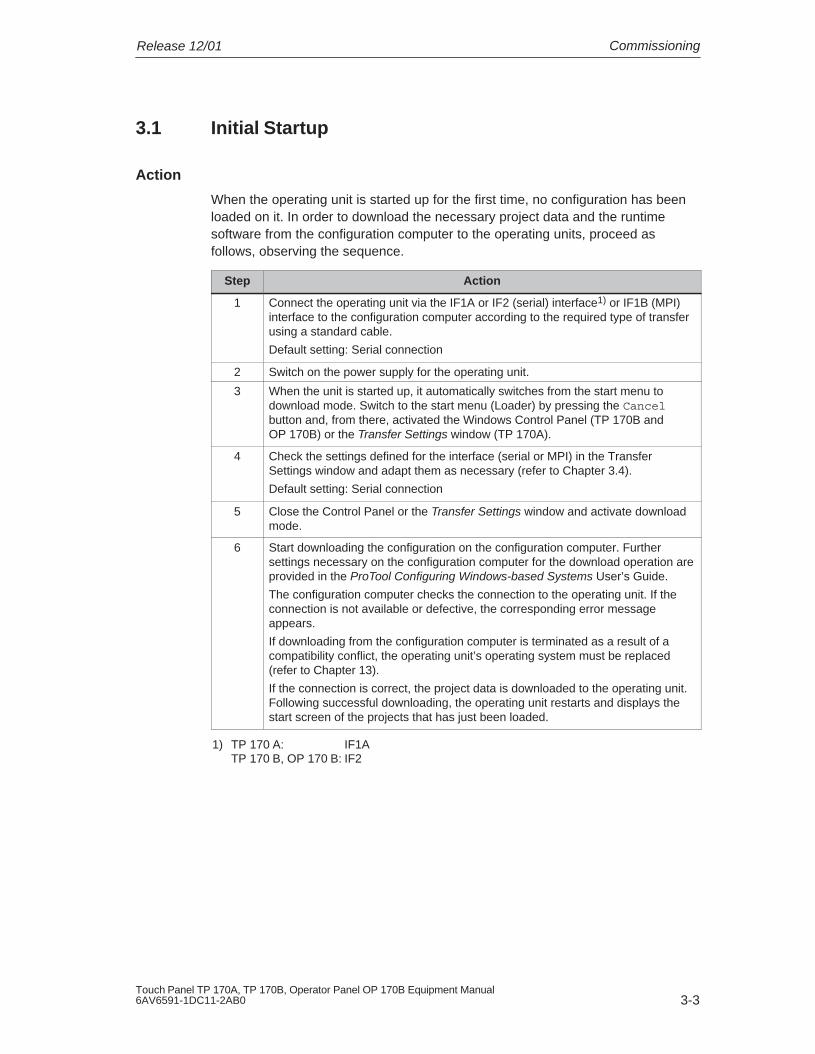
Action
When the operating unit is started up for the first time, no configuration has beenloaded on it. In order to download the necessary project data and the runtimesoftware from the configuration computer to the operating units, proceed asfollows, observing the sequence.
Step Action
1 Connect the operating unit via the IF1A or IF2 (serial) interface1) or IF1B (MPI)interface to the configuration computer according to the required type of transferusing a standard cable.
Default setting: Serial connection
2 Switch on the power supply for the operating unit.
3 When the unit is started up, it automatically switches from the start menu todownload mode. Switch to the start menu (Loader) by pressing the Cancelbutton and, from there, activated the Windows Control Panel (TP 170B andOP 170B) or the Transfer Settings window (TP 170A).
4 Check the settings defined for the interface (serial or MPI) in the TransferSettings window and adapt them as necessary (refer to Chapter 3.4).
Default setting: Serial connection
5 Close the Control Panel or the Transfer Settings window and activate downloadmode.
6 Start downloading the configuration on the configuration computer. Furthersettings necessary on the configuration computer for the download operation areprovided in the ProTool Configuring Windows-based Systems User’s Guide.
The configuration computer checks the connection to the operating unit. If theconnection is not available or defective, the corresponding error messageappears.
If downloading from the configuration computer is terminated as a result of acompatibility conflict, the operating unit’s operating system must be replaced(refer to Chapter 13).
If the connection is correct, the project data is downloaded to the operating unit.Following successful downloading, the operating unit restarts and displays thestart screen of the projects that has just been loaded.
1) TP 170 A: IF1ATP 170 B, OP 170 B: IF2

Commissioning Release 12/01
3-4Touch Panel TP 170A, TP 170B, Operator Panel OP 170B Equipment Manual
6AV6591-1DC11-2AB0
3.2 Recommissioning
Purpose
During recommissioning, a project already loaded on the operating unit is replacedby another. In this case, the project data is downloaded from the configurationcomputer to the operating unit.
The following options are available to switch the operating unit to download mode:
� Start downloading manually during the operating unit start-up phase
� Start downloading automatically while the operating unit is in operation
� Start downloading via a correspondingly configured operating element while theoperating unit is in operation (refer to Page 8-6).
3.2.1 Start downloading manually
Start downloading manually during the start-up phase of the operating unit:
Step Action
1 Connect the operating unit via the IF1A or IF2 (serial) interface1) or IF1B (MPI)interface to the configuration computer according to the required transfer settingsusing a standard cable.
2 Switch on the power supply for the operating unit.
3 Switch to the start menu (Loader) by pressing the Cancel button and, fromthere, activated the Windows Control Panel (TP 170B and OP 170B) or theTransfer Settings window (TP 170A).
4 Check the settings defined for the interface (serial or MPI) in the TransferSettings window and adapt them as necessary.
5 Close the Control Panel or the Transfer Settings window and activate downloadmode.
5 Start downloading the project on the configuration computer.
The configuration computer checks the connection to the operating unit. If theconnection is not available or defective, the configuration computer issues thecorresponding error message.
If downloading from the configuration computer is terminated as a result of acompatibility conflict, the operating unit’s operating system must be replaced(refer to Chapter 13).
If the connection is correct, the new configuration is downloaded to the operatingunit. Following successful transfer of data, the configuration is started and theunit displays the start screen of the configuration that has just been loaded.
1) TP 170 A: IF1ATP 170 B, OP 170 B: IF2

CommissioningRelease 12/01
3-5Touch Panel TP 170A, TP 170B, Operator Panel OP 170B Equipment Manual6AV6591-1DC11-2AB0
3.2.2 Start downloading automatically during normal operation
Download settings
The operating unit can be switched automatically to download mode from normaloperation as soon as downloading is started on the connected configurationcomputer. This option is particularly recommended for the test phase involving anew configuration project because the data is transferred without having tointervene on the operating unit.
A condition for this is that, with regard to the operating unit, the required transferconnection is set in the Transfer Settings window and the corresponding RemoteControl function is activated (TP 170A: Figure 3-3, TP 170B andOP 170B: Figure 3-4).
A detailed description of the possible download settings is provided on Page 3-7.
Close modal dialogs
If the Remote Control option is active, the runtime is automatically shut down andthe operating unit switched to download mode. If dialogs are still open, the runtimecannot be shut down when downloading has been started on the operating unit.
In such cases, close the dialog or interrupt downloading on the configurationcomputer.
Recommendation
Following the start-up phase, switch the automatic download option off to preventinadvertently switching the operating unit to download mode in a system which isrunning, which would cause the runtime to shut down. To do this, deactivate theRemote Control option in the operating unit Transfer Settings window (Figure 3-3or Figure 3-4).

Commissioning Release 12/01
3-6Touch Panel TP 170A, TP 170B, Operator Panel OP 170B Equipment Manual
6AV6591-1DC11-2AB0
3.3 Operating Unit Start Menu
During the start-up phase, the start menu (Loader) depicted below appears. Whenthe runtime has ended, the following appears:
� TP 170A
Figure 3-1 TP 170A start menu
Press the Transfer button to switch the operating unit to download mode.
Press the Start button to start the runtime automatically.
Press the Config button to call in the Transfer Settings menu in which to definethe options for download mode (refer to Figure 3-3 on Page 3-7).
Press the Control button to access a menu in which to define various settings,such as screen settings.
� TP 170B / OP 170B
Figure 3-2 TP 170B/OP 170B start menu (Loader)
Press the Transfer button to switch the operating unit to download mode.
Press the Start button to start the runtime automatically.
Press the Control Panel button to access the Windows CE Control Panel (seeFigure 8-2 on Page 8-7) in which various settings can be defined. The settingsfor the download mode options can be defined here, for example.
It is possible to protect the Start menu from unauthorized access by assigning apassword. If the password is subsequently not entered, only the Transfer andStart buttons are available. This prevents incorrect operation and increasessystem or machine security since settings cannot be modified.

CommissioningRelease 12/01
3-7Touch Panel TP 170A, TP 170B, Operator Panel OP 170B Equipment Manual6AV6591-1DC11-2AB0
3.4 Options for Download Mode
Overview
The following options can be set for download mode:
� Download mode can be restricted to a specific connection type so thatdownloading can only occur either via a serial connection or an MPI connection
� Automatic switching to download mode from normal operation when datatransfer is initiated from the connected configuration computer
Note
Modifications must not be carried out when the runtime is in operation or the unit isin download mode.
Download mode settings on the TP 170A
Access the configuration menu for defining the transfer settings by pressing theConfig button in the start menu.
Figure 3-3 TP 170A transfer settings menu
Select the required transfer channels and activate the respective Remote option. Inaddition to the serial transfer channel, a second channel can also be selected todownload data from the configuration computer to the operating unit.
The MPI/DP Transfer section displays both bus parameters, MPI Address andBaudrate. These parameters are valid for the project currently loaded on theoperating unit.
Press the OK button to confirm the settings currently defined for the downloadoptions. The Transfer Settings menu is closed and the start menu appears.

Commissioning Release 12/01
3-8Touch Panel TP 170A, TP 170B, Operator Panel OP 170B Equipment Manual
6AV6591-1DC11-2AB0
Download mode settings on the TP 170B/OP 170B
Access the configuration menu for defining the transfer settings by pressing theControl Panel button in the start menu. The Windows CE Control Panel is opened.Select the Transfer option.
Figure 3-4 Transfer settings configuration menu, Channel tab control,TP 170B and OP 170B
The Channel tab control in the Transfer Settings menu can be used to activate therequired transfer channel and the respective Remote Control option. In addition tothe serial transfer channel, a second channel can also be selected to downloaddata from the configuration computer to the operating unit.
Press the Advanced button to define the Address bus parameter setting andTransmission Rate and Highest Station network parameter settings fordownloading via MPI or PROFIBUS-DP. These parameters are valid for theconfiguration currently loaded on the operating unit.
In addition to the setting options for download mode, the Directories tab control canbe used to specify the following paths (refer to Figure 3-5):
Figure 3-5 Transfer settings configuration menu with Directories tab control

CommissioningRelease 12/01
3-9Touch Panel TP 170A, TP 170B, Operator Panel OP 170B Equipment Manual6AV6591-1DC11-2AB0
� Project FileThe predefined storage location for the project file can be changed here.The internal Flash memory or external Flash cards can be set for the operatingunits. During the next downloading process, the configuration is stored in thestorage location specified.
� Project BackupThe predefined storage location for the source file of your configuration can bechanged here. This file can be used for restoring (uploading) the configuration.External Flash cards can be set for the operating unit.
Information on uploading is provided on Page 3-13.
� Autostart application
PathThis defines the storage location for the ProTool runtime software. This is theapplication with which the configuration runs under Windows CE.
Wait
It is possible to define the number of seconds the Start menu should remain onscreen before the runtime is started (1 s, 3 s, 5 s, 10 s or constantly). If noruntime software is available, the unit automatically switches to downloadmode.
Notice
Do not change the default settings in the fields, except Wait, when working withProTool. Otherwise, the operating unit can no longer start the configuration.
Press the OK button or Enter key to confirm the settings currently defined for thedownload options. In the case of the OP 170B, ensure that no button has beenselected. The Transfer Settings menu is closed and the Windows CE ControlPanel is displayed.
Press the X button or ESC key to close the Transfer Settings menu and call in theWindows CE Control Panel. Any modifications made to the settings are rejected.
General information on download mode
!Warning
When the option Remote Control is active, ensure that the operating unit is notinadvertently switched to download mode from the configuration computer when innormal operation.

Commissioning Release 12/01
3-10Touch Panel TP 170A, TP 170B, Operator Panel OP 170B Equipment Manual
6AV6591-1DC11-2AB0
Notice
Deactivate the Remote Control option if the serial transfer channel has beenselected and a serial printer is connected to the operating unit. Otherwise, printingis not possible.
Notice
In the case of the TP 170A, Remote Transfer is not possible if serial transfer isactivated.
Notice
If no transfer channel has been enabled using the Enable Channel option, it is notpossible to download a configuration from the configuration computer to theoperating unit.
Note
The bus parameters for the MPI transfer (e.g. MPI address, baud rate, etc.) areread out of the configuration currently loaded on the operating unit.
The settings for MPI transfer can be modified. To do this, stop the runtime, modifythe settings and switch to download mode. When the runtime is subsequentlystarted, the bus parameters are overwritten by values from the configuration.
!Warning
In the case of Profibus-DP, modifications here may only be made for start uppurposes.
For each modification of the settings for Profibus-DP, the operating units only setone corresponding set of standard bus parameters. In unfavorable conditions, thiscan lead to faults on the DP bus.
In order to calculate the bus parameters exactly, the entire bus topology must beknown.
Correct definition of the bus parameters for runtime is automatically ensured bythe integrated operation of ProTool in STEP 7.

CommissioningRelease 12/01
3-11Touch Panel TP 170A, TP 170B, Operator Panel OP 170B Equipment Manual6AV6591-1DC11-2AB0
3.5 Test the Configuration
Conditions
In order to switch the operating unit between the operating modes OFFLINE andONLINE, the function Change_mode must be linked to an operating element in theproject.
NoteDuring the test phase, it is recommended to enable switching to download modefrom normal operation. Further information on this is provided on Page 3-5.
!Warning
After the test phase, do not forget to deactivate the Remote Control option toprevent inadvertently switching to download mode from the configuration computerwhen in normal operation.
Testing on the configuration computer
The material supplied with ProTool contains a simulation program which can beused to test the configuration on the configuration computer without the necessityof connecting a PLC or operating unit. Detailed information on this is provided inthe ProTool Configuring Windows-based Systems User’s Guide and in the onlinehelp to ProTool CS.
The simulation program can be started using the corresponding button in thetoolbar in ProTool
or via File → Test → Start Simulator.
Testing without a PLC connected (OFFLINE mode)
After setting the unit to OFFLINE mode, the individual functions of theconfiguration can be tested on the operating unit without them being affected bythe PLC. PLC tags are not updated in OFFLINE mode.
Step Action
1 Switch the operating unit to operating mode OFFLINE (refer to Page 8-6).
2 Check all the configured screens in respect of correct representation.
3 Check the screen hierarchy.
4 Check the input fields.
5 Test the function keys.

Commissioning Release 12/01
3-12Touch Panel TP 170A, TP 170B, Operator Panel OP 170B Equipment Manual
6AV6591-1DC11-2AB0
Testing with a PLC connected (ONLINE mode)
When a PLC is connected, it is possible to test the communication between theoperating unit and PLC in ONLINE mode. This includes checking that the correctdata areas have been configured.
Step Action
1 Connect the operating unit to the PLC.
2 Test all the items in the projects for which communication with the PLC isnecessary e.g.:
� messages
� print functions
� automatic message logging
� selecting screens etc.

CommissioningRelease 12/01
3-13Touch Panel TP 170A, TP 170B, Operator Panel OP 170B Equipment Manual6AV6591-1DC11-2AB0
3.6 Uploading (TP 170B and OP 170B)
Purpose
During downloading, only the run-capable configuration (*.fwd) which has beengenerated is normally downloaded on the operating unit. If the original source file isto be used for further development of the configuration or for fault analysis, it mustremain on the configuration computer.
Not only the generated configuration can be stored on the TP 170B and OP 170Bunits but also the source file, so that the configuration can be retrieved (uploaded)from the operating unit later, if necessary.
Advantage
After uploading a configuration back onto the unit, it can be analyzed and modifiedeven if the original cannot be accessed or the source file on it for the configurationis no longer available.
Conditions
The following conditions must be fulfilled in order to retrieve the source file from therun-capable project file:
� CF card with sufficient memory space,
� Downloading of the current project file from the configuration computer to theoperating unit must be performed using the option Upload. This option can beactivated in ProTool CS via File → Download → Preferences.
What happens during download/upload?
In the case of downloading including transfer of the source file, the configuration iscompressed from the source format (*.pdb) and downloaded to the operating unitas a *.pdz file. After uploading, the file is decompressed in the ProTool CSconfiguration software.
Following uploading, the configuration must be given a new name on theconfiguration computer.

Commissioning Release 12/01
3-14Touch Panel TP 170A, TP 170B, Operator Panel OP 170B Equipment Manual
6AV6591-1DC11-2AB0
Note
� The uploaded, decompressed source file can only be opened with aProTool CS whose version number is greater or equal to that of theconfiguration software with which the project was created.
� ProTool CS cannot check whether the source file on the operating unit matchesthe configuration actually run on it. If downloading is performed at any timewithout the Upload option being activated, it is possible that old project data ison the operating unit which no longer matches the current project.
Instructions
Uploading a project from the operating unit:
Step Action
1 Select the menu option File → Upload → Preferences in ProTool CS on theconfiguration computer.
2 Use the Upload dialog to select the required connection type between theoperating unit and configuration computer and to set the relevant connectionparameters.
3 Click on OK.
4 Switch the operating unit to download mode according to the setting in theTransfer Settings configuration menu.
5 Start the uploading function using the Upload → Start in ProTool.
6 Enter a new name or select an existing configuration to be overwritten and clickSave.
The configuration retrieved is saved and automatically opened in ProTool CS.

CommissioningRelease 12/01
3-15Touch Panel TP 170A, TP 170B, Operator Panel OP 170B Equipment Manual6AV6591-1DC11-2AB0
3.7 ProSave Service Tool
The ProSave tool is supplied together with ProTool. All the functions are providedwhich are necessary for the transfer of data between the configuration computerand operating unit:
� Data backup using Backup/Restore (Page 3-16)
� Installation and deinstallation of drivers, options and add-ons, i.e. applicationsand drivers independent of ProTool (for TP 170B and OP 170B only)
� License transfer (Page 3-21) (for TP 170B and OP 170B only)
Note
The ProSave tool can only be implemented from ProTool Version V6.0.
Integrated operation
ProSave is part of the material supplied with ProTool and can be automaticallyloaded on the configuration computer with the ProTool installation. The entirefunction range of ProSave is available within ProTool. In integrated operation, theProSave dialogs are called from the project. In this way, all the necessaryspecifications (e.g. target device and download settings) are assumed from theproject.
Stand-alone operation
ProSave can also be installed as a stand-alone application. In this case, thesettings concerning the device and downloading must be defined in the ProSaveuser interface and match the operating unit settings.

Commissioning Release 12/01
3-16Touch Panel TP 170A, TP 170B, Operator Panel OP 170B Equipment Manual
6AV6591-1DC11-2AB0
3.8 Backup/Restore the Internal Flash Memory
Purpose
The functions Backup and Restore provide the following options:
� creating a copy of the entire configuration on a memory card
� creating a copy of the entire configuration on PC (ProSave)
� copying selected objects, such as recipes and passwords, on PC (ProSave).
� restoring the stored elements in the case of a fault
� updating the operating unit regardless of where it is in use without the need of aconfiguration computer
Notice
If the restore process is interrupted due to a power failure, the operating system isdeleted. In this case, the operating system must be reloaded (refer to Chapter 13).
Note
If a message appears during the restore process indicating a compatibility conflicthas occurred, the operating system must be reloaded. Ensure that the sameversion of the operating system is loaded as was installed when the backup wascreated.
Note
Close all applications before starting the backup or restore process.
Note
Licenses on the TP 170B and OP 170B are not stored with the backup data.
Each restore initiated on the TP 170B and OP 170B deletes all the licenses on itpermanently. Therefore, save this data beforehand.

CommissioningRelease 12/01
3-17Touch Panel TP 170A, TP 170B, Operator Panel OP 170B Equipment Manual6AV6591-1DC11-2AB0
3.8.1 Backup/Restore on memory card (TP 170B and OP 170B)
During a backup process, the operating system, application and data are copiedfrom the internal Flash memory to an external storage medium.
In the case of a restore process, the content of a Flash memory stored on anexternal storage medium is reloaded into the internal Flash memory. Prior to this,the operating unit’s internal Flash memory is completely cleared followingconfirmation.
Backup on CF card
Proceed as follows to create a backup copy of the internal Flash memory:
Step Action
1 Deactivate the write protection on the memory card, if set.
2 Insert the memory card in the slot (TP 170B: Figure 9-2 on Page 9-9, OP 170B:Figure 9-3 on Page 9-11).
3 Call in the Windows CE Control Panel (refer to Page 3-6) and, fromthere, select the Backup/Restore option depicted on the right.
4 Start the Backup process by using the Backup button.
5 Confirm the deletion of any existing backup files beforehand.
6 When the data has been completely downloaded, the operating unit issues amessage.
7 Remove the memory card from the operating unit.
8 Activate the write protection on the memory card, if available.
9 Label the memory card, e.g. with the date and version of the configurationsaved, and keep it in a safe place.
Restore from CF card
Proceed as follows to restore the content of the internal Flash memory:
Step Action
1 Activate the write protection on the memory card, if available.
2 Insert the memory card in the slot (TP 170B: Figure 9-2 on Page 9-9, OP 170B:Figure 9-3 on Page 9-11).
3 Call in the Windows Control Panel and select the Backup/Restore option.
4 Start the restore process by clicking on the Restore button.
5 Confirm that the internal Flash memory.
6 After confirmation, the operating system is reloaded and the operating unit isautomatically restarted. Finally, the remaining data is downloaded.
7 When the data has been completely downloaded, the operating unit issues amessage.

Commissioning Release 12/01
3-18Touch Panel TP 170A, TP 170B, Operator Panel OP 170B Equipment Manual
6AV6591-1DC11-2AB0
ActionStep
8 Remove the memory card.
9 Restart the operating unit.
3.8.2 Backup/Restore using ProSave
In order to save the entire configuration, or even specific parts such as recipes andpasswords, on a PC use the ProSave service tool. The advantage of ProSave isthat the Backup/Restore can be performed via the following transfer channelswithout ProTool:
� Serial
� MPI / PROFIBUS-DP
During a backup process, the operating system, application and data are copiedfrom the internal Flash memory to a PC.
In the case of a restore process, the content of a Flash memory stored on the PCis reloaded into the internal Flash memory on the operating unit. Prior to this, theoperating unit’s internal Flash memory is completely cleared.
Backup using stand-alone ProSave
Creating a backup using ProSave as a stand-alone application:
Step Action
1 Start ProSave on the PC using the Windows Start menu.
2 Use the General tab register to select the required device type and connectiontype with corresponding connection parameters.
3 Use the Backup tab control to select the data to be saved (Recipes, Passwordsor Complete Backup).
4 Select the path in which the backup file (*.psb) should be saved.
5 Configure the operating unit according to the required transfer channel andswitch to download mode (Ch. 3.1 and Ch. 3.2).
6 Start the Backup process by using the Start backup button.
7 A progress indicator appears during the data transfer. When the transfer issuccessfully completed, a message appears briefly.

CommissioningRelease 12/01
3-19Touch Panel TP 170A, TP 170B, Operator Panel OP 170B Equipment Manual6AV6591-1DC11-2AB0
Backup using ProSave integrated in ProTool
Creating a backup using ProSave integrated in ProTool:
Step Action
1 In ProTool, select File → Download → Preferences and use the Set downloadwindow to define the connection type with the corresponding connectionparameters.
2 Open the Backup window in ProTool by selecting the menu items File →Download → Backup.
3 Select the data to be saved (Recipes, Passwords or Complete Backup).
4 Select the path in which the backup file (*.psb) should be saved.
5 Configure the operating unit according to the required transfer channel andswitch to download mode (Ch. 3.1 and Ch. 3.2).
6 Start the Backup process by using the Start backup button.
7 A progress indicator appears during the data transfer. When the transfer issuccessfully completed, a message appears briefly.
Restore using stand-alone ProSave
Proceed as follows to restore the content of the internal Flash memory:
Step Action
1 Start ProSave on the PC using the Windows Start menu.
2 Use the General tab register to select the required device type and connectiontype with corresponding connection parameters.
3 Use the Restore tab register to select the path in which the file to be restored islocated.
4 The Archive Description displays the unit concerned and the type of backup datacontained in the file.
5 Configure the operating unit according to the required transfer channel andswitch to download mode (Ch. 3.1 and Ch. 3.2).
6 Start the restore process by clicking on the Start restore button.
7 A progress indicator appears during the data transfer. When the transfer issuccessfully completed, a message appears briefly.

Commissioning Release 12/01
3-20Touch Panel TP 170A, TP 170B, Operator Panel OP 170B Equipment Manual
6AV6591-1DC11-2AB0
Restore using ProSave integrated in ProTool
Proceed as follows to restore the content of the internal Flash memory:
Step Action
1 In ProTool, select File → Download → Preferences and use the Transfer Settingswindow to define the connection type with the corresponding connectionparameters.
2 Open the Restore window in ProTool by selecting the menu items File →Download → Restore.
3 The Archive Description displays the unit concerned and the type of backup datacontained in the file.
4 Configure the operating unit according to the required transfer channel andswitch to download mode (Ch. 3.1 and Ch. 3.2).
5 Start the restore process by clicking on the Start restore button.
6 A progress indicator appears during the data transfer. When the transfer issuccessfully completed, a message appears briefly.

CommissioningRelease 12/01
3-21Touch Panel TP 170A, TP 170B, Operator Panel OP 170B Equipment Manual6AV6591-1DC11-2AB0
3.9 License Transfer (Authorization) using ProSave(TP 170B and OP 170B)
To protect the software, licenses supplied on a Siemens disk can be transferred tothe operating unit via a PC and enabled.
License transfer using stand-alone ProSave
License transfer to the operating unit:
Step Action
1 Start ProSave on the PC using the Windows Start menu.
2 Use the General tab register to select the required device type and connectiontype with corresponding connection parameters.
3 Select the Authorize tab control.
4 Select the disk drive containing the license disk.
5 The licenses available on the disk are displayed under Selection.
6 Select the required license.
7 Configure the operating unit according to the required transfer channel andswitch to download mode (Ch. 3.1 and Ch. 3.2).
8 Press the button depicted to transfer them to the operating unit.The selection appears in the Installed authorizations: field.
Deinstalling licenses from the operating unit:
Step Action
1 Start ProSave on the PC using the Windows Start menu.
2 Use the General tab register to select the required device type and connectiontype with corresponding connection parameters.
3 Select the Authorize tab control.
4 Configure the operating unit according to the required transfer channel andswitch to download mode (Ch. 3.1 and Ch. 3.2).
5 Press the Device Status button to display all the licenses installed on the operatingunit. These appear in the Installed authorizations: field.
6 Select the license to be deinstalled.
7 Press the button depicted to deinstall it from the operating unit.The selected licenses appear under Selection.

Commissioning Release 12/01
3-22Touch Panel TP 170A, TP 170B, Operator Panel OP 170B Equipment Manual
6AV6591-1DC11-2AB0
License transfer using ProSave integrated in ProTool
License transfer to the operating unit:
Step Action
1 In ProTool, select File → Download → Preferences and use the Set downloadwindow to define the connection type with the corresponding connectionparameters.
2 Open the Authorize window in ProTool by selecting the menu items File →Download → Authorize.
3 Select the disk drive containing the license disk.
4 The licenses available on the disk are displayed under Selection.
5 Select the required license.
6 Configure the operating unit according to the required transfer channel andswitch to download mode (Ch. 3.1 and Ch. 3.2).
7 Press the button depicted to transfer them to the operating unit.The selection appears in the Installed authorizations: field.
Deinstalling licenses from the operating unit:
Step Action
1 In ProTool, select File → Download → ����������� and use the Set downloadwindow to define the connection type with the corresponding connectionparameters.
2 Open the Authorization window in ProTool by selecting the menu items File →Download → Authorize.
3 Configure the operating unit according to the required transfer channel andswitch to download mode (Ch. 3.1 and Ch. 3.2).
4 Press the Device Status button to display all the licenses installed on the operatingunit. These appear in the Installed authorizations: field.
5 Select the license to be deinstalled.
6 Press the button depicted to deinstall it from the operating unit.The selected license appears under Selection.
Note
Uploading licenses can only be executed to a disk which contained or still containsthe same license.

CommissioningRelease 12/01
3-23Touch Panel TP 170A, TP 170B, Operator Panel OP 170B Equipment Manual6AV6591-1DC11-2AB0
3.10 Loading Applications with ProSave(TP 170B and OP 170B)
Applications (e.g. drivers) specially developed for the operating unit can beinstalled on the operating unit using ProSave.
Load applications using stand-alone ProSave
Loading applications on the operating unit:
Step Action
1 Start ProSave on the PC using the Windows Start menu.
2 Use the General tab register to select the required device type and connectiontype with corresponding connection parameters.
3 Select the Options tab control.
4 Use Selection to select the path containing the required application.
5 The corresponding application is displayed under Available options:.
Select the required application.
6 Configure the operating unit according to the required transfer channel andswitch to download mode (Ch. 3.1 and Ch. 3.2).
7 Press the button depicted to transfer them to the operating unit.The selection appears in the Installed options: field.
Deinstalling an application from the operating unit:
Step Action
1 Start ProSave on the PC using the Windows Start menu.
2 Use the General tab register to select the required device type and connectiontype with corresponding connection parameters.
3 Select the Options tab control.
4 Configure the operating unit according to the required transfer channel andswitch to download mode (Ch. 3.1 and Ch. 3.2).
5 Press the Device Status button to display all the applications installed on theoperating unit. These appear in the Installed options: field.
6 Select the application to be deinstalled.
7 Press the button depicted to deinstall it from the operating unit.The selected application appears under Available options:.

Commissioning Release 12/01
3-24Touch Panel TP 170A, TP 170B, Operator Panel OP 170B Equipment Manual
6AV6591-1DC11-2AB0
Load applications using ProSave integrated in ProTool
Loading applications on the operating unit:
Step Action
1 In ProTool, select File → Download → Preferences and use the Set downloadwindow to define the connection type with the corresponding connectionparameters.
2 Open the Options window in ProTool by selecting the menu items File →Download → Options.
3 Use Selection to select the path containing the required application.
4 The corresponding application is displayed under Available options:. Select therequired application.
5 Configure the operating unit according to the required transfer channel andswitch to download mode (Ch. 3.1 and Ch. 3.2).
6 Press the button depicted to transfer them to the operating unit.The selection appears in the Installed options: field.
Deinstalling an application from the operating unit:
Step Action
1 In ProTool, select File → Download → Preferences and use the Set downloadwindow to define the connection type with the corresponding connectionparameters.
2 Open the Options window in ProTool by selecting the menu items File →Download → Options.
3 Configure the operating unit according to the required transfer channel andswitch to download mode (Ch. 3.1 and Ch. 3.2).
4 Press the Device Status button to display all the licenses installed on the operatingunit. These appear in the Installed options: field.
5 Select the application to be deinstalled.
6 Press the button depicted to deinstall it from the operating unit.The selected application appears under Available options:.

4-1Touch Panel TP 170A, TP 170B, Operator Panel OP 170B Equipment Manual6AV6591-1DC11-2AB0
Operation
In this chapter
The OP 170B is operated via an integrated membrane keyboard, the TP 170A andTP 170B via buttons or a screen keyboard.
This chapter provides information on the general operating procedures of the
� TP 170A and TP 170B (Page 4-1)
� OP 170B (Page 4-8)
4.1 Operating the TP 170A and TP 170B Touch Panels
Overview
The screen is used to observe the operating status of the machine or system beingmonitored and, at the same time, to intervene directly in the process runningsimply by touching the buttons and input fields displayed.
4.1.1 Operating touch elements
Definition
Touch elements are contact-sensitive operating elements provided on the touchpanel screens, such as buttons, input fields and message windows. Theiroperation is basically no different from pressing conventional keys. Touchelements are operated by touching them, e.g. with a finger.
!Caution
Be sure to touch only one touch panel screen element. Never touch more thanone touch element at a time. Otherwise, an action may be unintentionally initiated.
4

Operation Release 12/01
4-2Touch Panel TP 170A, TP 170B, Operator Panel OP 170B Equipment Manual
6AV6591-1DC11-2AB0
Note
Never use pointed or sharp instruments to operate the touch panels to preventdamage to the plastic surface of the touch screen.
Direct keys on the TP 170B
In the case of a DP connection, buttons can be configured as direct keys in orderto achieve fast keyboard operation. Fast key operation is a condition for Joggingmode (Inching mode), for example.
PROFIBUS direct keys set bits in the I/O area of a SIMATIC S7 directly from theTP 170B.
Operation acknowledgement
As soon as the touch panel detects an element has been touched, it responds bydisplaying a visual acknowledgement. An acknowledgment is independent ofcommunication with the PLC. It is not an indication of the required action actuallyhaving been executed.
The type of visual acknowledgement is dependent on the operating elementtouched:
� Buttons
In the case of 3D-effect configurations, visual representation is distinguishedaccording to the statuses touched and untouched. The way in which theselected field appears on the screen can be configured (line widths 1 - 10 forthe focus and the color of the frame). Examples of representation are illustratedbelow by means of the Status button.:
UntouchedTouched
� Hidden buttons (TP 170B only)The focus for hidden buttons does not appear following selection (value for thefocus line width is 0, default setting). If the value for the focus width is changed,the dotted outline of the button changes to a line when touched. The outlinesremain visible until the focus is moved to another operating element.
� Input fields
After touching an input field, the screen keyboard appears as the operationacknowledgement.

OperationRelease 12/01
4-3Touch Panel TP 170A, TP 170B, Operator Panel OP 170B Equipment Manual6AV6591-1DC11-2AB0
Operating screen objects using buttons
Screen objects which are assigned pre-defined buttons can also be operated bybuttons outside the screen object. A condition for this is that each function hasbeen linked to the respective button in the configuration.
These functions are complied in ProTool CS within the Keyboard action for screenobjects.
4.1.2 Enter numeric values
Numeric screen keyboard
In order to enter numeric and hexadecimal values, the touch panel automaticallydisplays a numeric screen keyboard directly after touching an input field on thetouch screen. Keys on the keyboard which are available for operation arehighlighted as 3D keys, those not available are simply displayed as areas. Aftercompleting the input, the screen keyboard is automatically hidden.
Note
Keys cannot be operated if they have been used to operate a decimal fieldbeforehand.
All keys continue to be operable when they have been used to operate ahexadecimal field.
Figure 4-1 illustrates an example of the screen keyboard for entering numericvalues. The keys A to F for entering hexadecimal values are inoperable in thisexample.
The Help key (TP 170B) is only active when a help text has been configured forthat particular input field.

Operation Release 12/01
4-4Touch Panel TP 170A, TP 170B, Operator Panel OP 170B Equipment Manual
6AV6591-1DC11-2AB0
Figure 4-1 Screen keyboard for numeric values
The BSP key corresponds to the Backspace key.
Action
Numeric and hexadecimal values are entered character by character using thebuttons provided on the screen keyboard. Invalid characters are rejected and anerror message appears. Confirm the value entered by pressing the Enter key orcancel the input by pressing ESC. The screen keyboard is closed in both cases.
Note
Limit values can be configured for numeric input fields. In this case, valuesentered are only accepted when they lie within the limits configured. If an attemptis made to enter a value which is outside the configured limits, it is rejected andthe original value automatically reinserted. In this case, the operating unit issues asystem message.
Note
When the keyboard is displayed, the lower and upper limit values are indicated,when configured.
Note
If the full screen keyboard is open, the PLC job 51 Changing Screen has nofunction.

OperationRelease 12/01
4-5Touch Panel TP 170A, TP 170B, Operator Panel OP 170B Equipment Manual6AV6591-1DC11-2AB0
4.1.3 Enter alphanumeric values
Alphanumeric screen keyboard
In order to enter a character string, the touch panel automatically displays a fullscreen alphanumeric keyboard directly after touching an input field on the touchscreen. After completing the input, the screen keyboard is automatically hidden.
Keyboard levels
The full screen keyboard has an alphanumeric layout providing normal and Shiftlevels. Toggle between the two levels by pressing the SHIFT key.
The Help key (TP 170B) is only active when a help text has been configured forthat particular input field.
An example of the keyboard’s normal level is illustrated:
Figure 4-2 Screen keyboard for alphanumeric values, normal level
Note
The BSP key corresponds to the Backspace key.
A summary of the key functions is provided in Table 4-1 on Page 4-11.

Operation Release 12/01
4-6Touch Panel TP 170A, TP 170B, Operator Panel OP 170B Equipment Manual
6AV6591-1DC11-2AB0
Action
Alphanumeric values are entered character by character using the buttonsprovided on the full screen keyboard. Confirm the value entered by pressing theEnter key or cancel the input by pressing ESC. The screen keyboard is closed inboth cases.
Note
If the full screen keyboard is open, the PLC job 51 Select Screen has no function.
4.1.4 Calling in help text on the TP 170B
Purpose
Help texts consist of additional information and operating instructions provided bythe configuration planner concerning messages, screens and input fields. Helptext, concerning an input field for example, may provide information on permissiblevalue ranges (refer to Figure 4-3) or, in the case of an alarm message, informationrelated to the cause and its elimination.
Enter temperature setpoint for Tank_1(Range 40...80 �C)
Figure 4-3 Help text for an input field (example)

OperationRelease 12/01
4-7Touch Panel TP 170A, TP 170B, Operator Panel OP 170B Equipment Manual6AV6591-1DC11-2AB0
Action
� Help on messages Touch the following button in the message window, on the message page, inthe message buffer or the message display
� Help on input fieldsTouch the Help key on the screen keyboard. This key only appears if aconfigured help text exists.
� Help on current screenIf the function Display Help Text has been assigned to a button in the project,for example, touch that button to call in the help text configured for the currentscreen.

Operation Release 12/01
4-8Touch Panel TP 170A, TP 170B, Operator Panel OP 170B Equipment Manual
6AV6591-1DC11-2AB0
4.2 Operating the OP 170B Keyboard Unit
Overview
The operating status of the machine or system to be monitored can be observed inthe OP 170B screen and the running process directly influenced by using theintegrated membrane keyboard.
This chapter provides information on the general operating procedures for theOP 170B.
Information regarding operation for special screen objects is provided in Chapter 6.
4.2.1 Integrated keyboard
Keypads
The OP 170B keyboard consists of two functional blocks (Figure 4-4):
� Function keys/Soft keys (keys K1 to K10 and F1 to F14)
� System keys
Figure 4-4 Assignment of the OP 170B keypads

OperationRelease 12/01
4-9Touch Panel TP 170A, TP 170B, Operator Panel OP 170B Equipment Manual6AV6591-1DC11-2AB0
4.2.2 Function keys/Softkeys
Function keys with global function assignment
A function key with global function assignment always triggers the same action onthe OP 170B or in the PLC regardless of the screen currently open (globalsignificance on the OP 170B). These actions could include:
� Open screen
� Display current alarm messages
� Print screen (hardcopy)
All F and K keys can be assigned globally significant functions.
Function keys with local function assignment (softkeys)
A function key with local function assignment (softkey) can trigger different actionson the OP 170B or in the PLC according to the screen currently open (localsignificance of current screen). An icon can be configured for each softkey whichcan then be positioned at the edge of the screen.
All the function keys located directly at the edge of the screen can be assignedlocally significant functions during configuration. In the case of the OP 170B, thisrelates to the keys F1 to F14.
!Caution
If a function key is pressed directly following changing screens, the correspondingfunction associated with the new screen can be triggered before the screen isgenerated.

Operation Release 12/01
4-10Touch Panel TP 170A, TP 170B, Operator Panel OP 170B Equipment Manual
6AV6591-1DC11-2AB0
4.2.3 System keys
Control keys
The following control keys serve superordinated editing and control functions:
Tabulator
Insert/Delete
Backspace
Shift (numeric/alphanumeric)
Acknowledge
Escape (Terminate)
Display help text
Ctrl key
Alt key
Confirm entry
Shift (upper/lower case)
Figure 4-5 Control keys
The system keys ACK, ESC, HELP and ENTER can also be assigned functions.
Note
A two-key operation is possible for the OP 170B , i.e. two keys can be pressedthus triggering two functions (refer to Communication for Windows-based SystemsUser’s Guide).
Cursor keys
The cursor keys (Figure 4-6) are used to move the text cursor and to navigate inscreens and screen objects. The functions of the keys corresponds to the cursorkeys on a standard PC keyboard.
Figure 4-6 Cursor keys
The Home and End keys can also be assigned functions.

OperationRelease 12/01
4-11Touch Panel TP 170A, TP 170B, Operator Panel OP 170B Equipment Manual6AV6591-1DC11-2AB0
System key function overview
Table 4-1 Functions of the system keys
Key Function Purpose
Shift Switches the assignment of the input keysfrom numeric to alphanumeric input.
� No LED lights up:Numeric assignment is active. Press thekey once to switch to alphanumericassignment.
� An LED lights up:The left or right alphanumeric assignmentis active. Each time the key is pressedswitches through left, right and off.
Delete character � Deletes an individual characters.
Delete character in numeric keyboardassignment. To insert characters, use theShift key to switch to alphanumericassignment.
Cancel � Deletes the character of a value enteredand resets the original value.
� Closes the active window.
Acknowledge Acknowledges the currently displayed alarmmessage or all messages in anacknowledgment group (groupacknowledgement).
The LED lights up as long asunacknowledged alarm messages arequeued.
Display help text Opens a window with help text in respect ofthe selected object (message, input field). TheLED indicates if help text exists for theselected object.
Acknowledge � Accepts and ends the input.
� Opens a selection field for symbolic input.
� Triggers the function on the selectedbutton.
Tabulator Moves to the next screen object available forselection in the configured tabulationsequence.
Delete character Deletes the character to the left of the cursor.
Move cursor � Move to the next screen object availablefor selection to the right, left, above orbelow the current screen object.
� Navigation in the screen object.

Operation Release 12/01
4-12Touch Panel TP 170A, TP 170B, Operator Panel OP 170B Equipment Manual
6AV6591-1DC11-2AB0
Table 4-1 Functions of the system keys, continued
PurposeFunctionKey
General controlfunction
Only use in combination with other keys,navigation in trend views (Page 6-34).
Shift (upper/lowercase)
Only use in combination with other keys, e.g.shift to capital letters.
General controlfunction
Only for use with key combinations, e.g. openselection field (Page 4-12).
Scroll back Scroll one page back.
Scroll forward Scroll one page forward.
4.2.4 Key combinations
General operation
Table 4-2 Key combinations
Key combination Function
Navigation
Moves to the previous screen object available for selection in theconfigured tabulation sequence.
Positions the cursor within a screen object, e.g. in an input field.
Skip to the start, e.g. of a selection list.
Skip to the end, e.g. of a selection list.
Opens a selection field.
Screen settings
Increase the screen contrast.
Reduce the screen contrast.

OperationRelease 12/01
4-13Touch Panel TP 170A, TP 170B, Operator Panel OP 170B Equipment Manual6AV6591-1DC11-2AB0
Table 4-2 Key combinations, continued
FunctionKey combination
During the start-up phase
Switches the OP 170B to download mode.
As long as no data transfer is taking place, it is possible to exitfrom download mode.
Other functions
Accepts the selected value in the selection field without closing it.
� Changes the active window.
� Switches between basic area and window.
Mark all
Display the properties of the marked element
Move to next field
Move to previous field
Opens the next tab control 1)
Opens the previous tab control 1)
Close the dialog without saving.
1) When the name of the tab control has the focus
Operating screen objects using function keys
Screen objects assigned to buttons, e.g. message display, trend viewrepresentation or recipe view, can also operated by means of function keys orsoftkeys. A condition for this is that each relevant function has been linked to afunction key or softkey in the project.
These functions are complied in ProTool CS within the Keyboard action for screenobjects.

Operation Release 12/01
4-14Touch Panel TP 170A, TP 170B, Operator Panel OP 170B Equipment Manual
6AV6591-1DC11-2AB0
4.2.5 Entering values
Marking
On selecting an input field, the entire field content is marked by changing color.After pressing a key (except a cursor key), the field content is deleted and the newinput displayed.
After selecting a field, press the SHIFT key and a cursor key simultaneously to clearthe marking on the field contents and enable the cursor to be moved freely withinthe field.
Note
To enter the hexadecimal characters A...F, switch the input keys to alphanumericassignment.
Note
Limit values can be configured for numeric input fields. In this case, valuesentered are only accepted when they lie within the limits configured. If an attemptis made to enter a value which is outside the configured limits, it is rejected andthe original value automatically reinserted. In this case, the operating unit issues asystem message.
Note
On entering the first character, a tooltip appears with the lower and upper limitvalues related to the input window.

OperationRelease 12/01
4-15Touch Panel TP 170A, TP 170B, Operator Panel OP 170B Equipment Manual6AV6591-1DC11-2AB0
4.3 Calling in Help Text on the OP 170B
Purpose
Help texts consist of additional information and operating instructions provided bythe configuration planner concerning messages, screens and operable screenobjects. Help text, concerning an input field for example, may provide informationon permissible value ranges (refer to Figure 4-7) or, in the case of an alarmmessage, information related to the cause and its elimination.
Enter temperature setpoint for Tank_1(Range 40...80 �C)
Figure 4-7 Help text for an input field (example)
Note
If the PLC job 51 Select screen is triggered when a help window is open, the newscreen is selected and the help window is closed.
Action
Proceed as follows in order to call in the configured help text, e.g. for an input field:
Step Action
1 Select input field(e.g.)
The input field is marked.
2 Call in the help text The LED in the key lights up, indicating thathelp text is available. Press the key to call inthe help text.
The configured help text is displayed in thelanguage currently set on the OP 170B.
If help text is also configured for the currentpicture, it is displayed after pressing the keyagain.
3 Close help window The help window is closed.

Operation Release 12/01
4-16Touch Panel TP 170A, TP 170B, Operator Panel OP 170B Equipment Manual
6AV6591-1DC11-2AB0

5-1Touch Panel TP 170A, TP 170B, Operator Panel OP 170B Equipment Manual6AV6591-1DC11-2AB0
TP 170A Screen Objects
In this chapter
This chapter provides general information on screens and operating predefinedscreen objects on the TP 170A.
Information on the general operation procedures for the TP 170A is provided inChapter 4.1.
5.1 Operating Screens
What is a screen?
Screens visualize the progress of processes and display specified process values.A screen contains logically related process data which the operating unit can bothdisplay and modify by operating the individual values.
Screens display the current process status in the form of numeric values, bargraphs or trend curves for example. Dynamic screen objects enable, for instance,the current position of a production process to be tracked on the operating unit.
Screen partitions
A screen is basically composed of static and dynamic sections. The terms “static”and “dynamic” do not refer to the possibility of dynamically positioning screenpartitions but to the connection to the PLC.
Static partitions, e.g. text and graphics, are not updated by the PLC. Dynamicpartitions, e.g. input and output fields, trend curves and bars, are linked to the PLCand display current values constantly read in from the PLC memory. Theirconnection to the PLC is established by means of tags.
A summary of all the screen objects which the operating unit may contain isprovided on Page 5-4.
5

TP 170A Screen Objects Release 12/01
5-2Touch Panel TP 170A, TP 170B, Operator Panel OP 170B Equipment Manual
6AV6591-1DC11-2AB0
Select screen
The operating unit can be used to view, edit and print screens. The relevant screenmust have been selected beforehand. It is possible to select a screen by pressinga button which has been assigned to that particular screen in the configuration.
Note on configuration
Press the key with which the screen should be selected. Select the Select_screenfunction and enter a name for the screen under the Screen Name parameter. Inthe Field Number box, enter the Tab key sequence number of the field in whichcursor should be located following a change of screens. As soon as the key issubsequently pressed, the function is triggered and the content of the ScreenName and Field Number parameters evaluated. The corresponding screen isdisplayed on the operating unit.
5.2 Logging On and Off
Purpose
Operable screen objects, such as input fields and buttons, can be assignedpasswords during configuration to prevent them being modified by unauthorizedpersonnel. Important parameters and settings can then only be modified byauthorized personnel.
Information on the Password List screen object is provided on Page 6-35.
Login
In order to access password protected operating elements, it is necessary to log inon the operating unit. In this case, the function Logon_User must be linked with aninput field, for example, in the configuration. It is then possible to access allpassword protected operating elements up to the point of logging off from theoperating unit.
When correspondingly configured, it is also possible to log on via an input field forconfidential password entry. The character string entered is represented byplaceholders (*).

TP 170A Screen ObjectsRelease 12/01
5-3Touch Panel TP 170A, TP 170B, Operator Panel OP 170B Equipment Manual6AV6591-1DC11-2AB0
Logoff
In order to rule out operation by unauthorized personnel, the login should notremain active on the operating unit for too long a period of time. The followingoptions are available with which to log off from the operating unit:
� Configured logout time expiresIf the operating unit is not operated by the user within the configured period(logout time), he is automatically logged off from the operating unit.
� Log offIf the configuration links the function Logoff_User with an operating element,the element can be used log off from the operating unit.
NoteIt is possible to log off by entering an incorrect password.

TP 170A Screen Objects Release 12/01
5-4Touch Panel TP 170A, TP 170B, Operator Panel OP 170B Equipment Manual
6AV6591-1DC11-2AB0
5.3 Overview of Screen Objects
A summary of the various screen objects which a TP 170A configuration maycontain is provided in the following table.
Table 5-1 Screen objects configurable for the TP 170A
Screen object Use/Description
Text Text is used during configuration to label operating anddisplay elements, for example. Text can be configuredover several lines and cannot be altered on theoperating unit.
Graphics Graphics can be used in the configuration, e.g. torepresent a system or as an illustrative symbol forconfigured display and operating elements.
Output field The output field displays the current value in numericor alphanumeric form.
Input field Enter a value in the input field. The values can be innumeric or alphanumeric form. Entries which lieoutside the specified value range are rejectedaccording to the limit values which have beenconfigured.
The input can be protected by means of a password.
Status button A Status button is a display and operating elementwhich has one of two states: Touched and Untouched.The states can be indicated by means of text orgraphics.
The Status button can be configured to be locking(switch function) or non–locking (keying function).
State view (alarm lamps) The state views can be used to configure a warningdisplay or indicate the status of a unit which cannot beviewed from the operating unit (e.g. a motor).
The response of the state view can be configured.
Bar Bar graphs present a value in the form of a rectangulararea. The operating unit thus provides a clearindication of how far the current value is from the limitvalues, or if a setpoint value has been reached, at aglance. Bars are often used to represent fill levels orworkpiece numbers.
Direction, scaling and labeling the axis can beconfigured as required. In order to identify limit values,limit value lines can be called in.
Single message display Special filter criteria for displaying pending messagesare configured in the message view.
Notes on operation are provided on Page 5-10.

TP 170A Screen ObjectsRelease 12/01
5-5Touch Panel TP 170A, TP 170B, Operator Panel OP 170B Equipment Manual6AV6591-1DC11-2AB0
5.4 Input Field
Purpose
Numeric or alphanumeric values are entered character by character in an inputfield. A numeric value is a number, e.g. 80 as a setpoint value for a temperature.An alphanumeric value can contain text and digits e.g. Valve_12.
Limit value check
If limit values are configured for the input field tags, the values entered are onlyaccepted when they are within the configured limits. If an attempt is made to entera value which is outside the configured limits, it is rejected and the original valueautomatically reinserted. In this case, the operating unit issues a system message.
Display
Input fields can be configured differently according to their purpose, e.g.:
� Numeric input field
to enter numeric values in decimal, hexadecimal or binary format.
� Alphanumeric input field
to enter character strings. It is only possible to enter ASCII characters. Theyare dependent on the language selected.
� Input field for date and timeto enter the calendar date and time. The format is dependent on the languagecurrently set on the operating unit. The figure below illustrates examples ofinput fields for date and time in US English language format.
� Input field for confidential password entry
to enter passwords confidentially. The character string entered is representedby placeholders (*). The figure below illustrates an example.

TP 170A Screen Objects Release 12/01
5-6Touch Panel TP 170A, TP 170B, Operator Panel OP 170B Equipment Manual
6AV6591-1DC11-2AB0
Operation
Proceed as follows to operate an input field:
� Touch the input field on the TP 170A touch screen. The screen keyboardautomatically appears.
� Enter the required value.
� Confirm the entry
or
� Discard the entry.

TP 170A Screen ObjectsRelease 12/01
5-7Touch Panel TP 170A, TP 170B, Operator Panel OP 170B Equipment Manual6AV6591-1DC11-2AB0
5.5 Status Button
Purpose
The Status button is an operating and display element with the two states Pressedand Released. Status buttons can indicate the status of units which cannot beseen by the operator (e.g. a motor). At the same time, it is also possible to changethe status of the device concerned on the operating unit.
Behavior
The behavior of the Status button can be configured:
� Switch: The switch has two stable states. It toggles from one state to the other eachtime it is operated, and remains in the respective state until it is operated again.
� Key: The button has a fixed, stable home position. When operated, it switches to thestatus pressed and remains in this state as long as it is kept pressed. Whenreleased, it automatically switches back to its released position.
Functions which have been assigned to the Status button can be triggered, forexample, by the following configurable events:
� Status change
� Printing
� Releasing
If the status of a switch type Status button changes as a result of a modification ofconfigured tags, not through operation, the corresponding function is not executed.
Display
The two indicator statuses of the types Switch and Button with acknowledgementcan be assigned different texts or graphics in ProTool CS which are displayed onthe Status button during runtime.
Figure 5-1 illustrates an example of a switch type Status button when pressed (left)and not pressed (right).
Figure 5-1 The two statuses relate to the Status button when the Switch option is set
Operation
Touch the Status button on the operating unit.

TP 170A Screen Objects Release 12/01
5-8Touch Panel TP 170A, TP 170B, Operator Panel OP 170B Equipment Manual
6AV6591-1DC11-2AB0
Note
Release
In the case of a button, a function is triggered when the pressed button isreleased.
If the button is pressed using the mouse button or finger (when using touchpanels) but moved outside, the function is triggered when the function is released.
Press
In the case of a button, a function is triggered as soon as the button is pressed.

TP 170A Screen ObjectsRelease 12/01
5-9Touch Panel TP 170A, TP 170B, Operator Panel OP 170B Equipment Manual6AV6591-1DC11-2AB0
5.6 Bar Graphs
Purpose
Bar graphs present a value in the form of a rectangular area. The operating unitthus provides a clear indication of how far the current value is from the limit values,or if a setpoint value has been reached, at a glance. Bar graphs can be used todisplay fill levels or quantities, for example.
Display
It is possible to configure minimum and maximum values and the direction bargraph moves by increasing the tag value:
Figure 5-2 depicts the various states of a horizontal bar graph:
1. Value drops below the minimum value configured
2. Value lies within the configured display range
3. Value exceeds the maximum value configured
4. Value lies within the configured limit range
Figure 5-2 Different bar states

TP 170A Screen Objects Release 12/01
5-10Touch Panel TP 170A, TP 170B, Operator Panel OP 170B Equipment Manual
6AV6591-1DC11-2AB0
5.7 Messages
Message categories
Messages which appear on the operating unit indicate events and statuses relatedto the control process and operating unit itself. A message can contain text andtags.
The TP 170A can display event and system messages:
� Event messagesindicate a status in the process, for example, Motor ON.Event messages are configured. They are triggered when a bit is set in thePLC.
� HMI System Messagesare triggered by the operating unit. They are not configured.System messages indicate, for example, incorrect operations or communicationfaults. A selection of important system messages is provided in Appendix C.
Message events (not system messages)
These messages are triggered according to events. Message events on theTP 170A include:
� Message arrivalA message which has been triggered is considered as having arrived. As soonas message is triggered, it is displayed in the operating unit message view andis then considered as queued.
� Message departureA message is considered as having departed when its configured time periodhas expired or the event causing the message is no longer present. As soon asa message has departed it is deleted from the message view.
Message view
The TP 170A displays messages which have arrived in the message view. Ifseveral messages are stored in the operating unit buffer simultaneously, the oldestmessage in the buffer is overwritten in the case of a message buffer overflow.
Specific views of the messages to be displayed are defined in the message view.Various filter criteria is available for this in the configuration software.
The following can be configured
� Message categories (event and system messages)
� Number of columns
� Number of lines per message
� Sorting (oldest or latest message at the top)
� Maximum number of visible messages
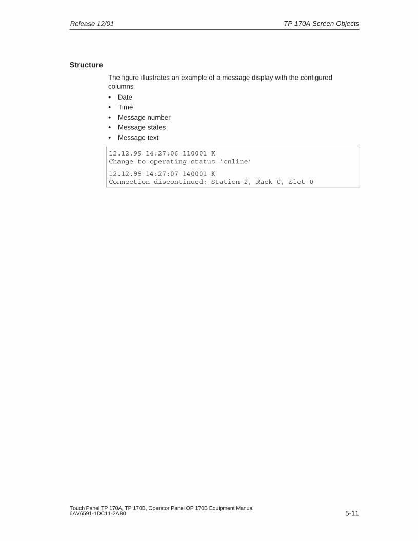
TP 170A Screen ObjectsRelease 12/01
5-11Touch Panel TP 170A, TP 170B, Operator Panel OP 170B Equipment Manual6AV6591-1DC11-2AB0
Structure
The figure illustrates an example of a message display with the configuredcolumns
� Date
� Time
� Message number
� Message states
� Message text
12.12.99 14:27:06 110001 K Change to operating status ’online’
12.12.99 14:27:07 140001 K Connection discontinued: Station 2, Rack 0, Slot 0

TP 170A Screen Objects Release 12/01
5-12Touch Panel TP 170A, TP 170B, Operator Panel OP 170B Equipment Manual
6AV6591-1DC11-2AB0

6-1Touch Panel TP 170A, TP 170B, Operator Panel OP 170B Equipment Manual6AV6591-1DC11-2AB0
TP 170B and OP 170B Screen Objects
In this chapter
Operation of the visualization processes on the operating unit is dependent on theconfiguration created with the ProTool CS configuration software. This chapterprovides general information on screens and operating predefined screen objectson the TP 170B touch panel and OP 170B keyboard unit.
Information on the general operation procedures for the TP 170B touch panel isprovided in Chapter 4.1. Information on the general operating procedures of theOP 170B keyboard unit provided in Chapter 4.2.
6.1 Operating Screens
What is a screen?
Screens visualize the progress of processes and display specified process values.A screen contains logically related process data which the operating unit can bothdisplay and modify by operating the individual values.
Screens display the current process status in the form of numeric values, bargraphs or trend curves for example. Dynamic screen objects enable, for instance,the current position of a production process to be tracked on the operating unit.
Screen partitions
A screen is basically composed of static and dynamic sections. The terms “static”and “dynamic” do not refer to the possibility of dynamically positioning screenpartitions but to the connection to the PLC.
Static partitions, e.g. text and graphics, are not updated by the PLC. Dynamicpartitions, e.g. input and output fields, trend curves and bars, are linked to the PLCand display current values constantly read in from the PLC memory. Theirconnection to the PLC is established by means of tags.
A summary of all the screen objects which the operating unit may contain isprovided in Chapter 6.3.
6

TP 170B and OP 170B Screen Objects Release 12/01
6-2Touch Panel TP 170A, TP 170B, Operator Panel OP 170B Equipment Manual
6AV6591-1DC11-2AB0
Fixed window
The fixed window is an area at the top of the screen. The height of the fixedwindow can be configured. Since the content of the fixed window is independent ofthe screen currently displayed, it is especially suited for displaying importantprocess magnitudes or date and time.
An operating element configured in the fixed window is available in every screen.When using touch panels, for example, a button can be configured in the fixedwindow to represent a globally effective function key.
OP 170B icons
Icons are graphics of a fixed size located at the bottom and sides of the screen.They are defined during configuration and clearly indicate the screen-specificfunctions of the softkeys in graphic form.
After pressing the respective softkey, the function symbolized by the icon isactivated either on the OP 170B or the PLC.
Message indicator
The message indicator is a configurable graphical symbol which isdisplayed on the screen when at least one alarm message is present orneeds to be acknowledged on the operating unit.
The indicator continues to blink as long as unacknowledged messagesare present.The number (in this case 3) represents the number of alarm messagespresent.
In the case of the TP 170B, the message indicator can be operated.
Operating the message indicator on the TP 170BThe response of the message indicator is dependent on whether or not alarmmessages are present on the TP 170B which still have to be acknowledged at themoment the indicator is touched.
� Alarm messages to be acknowledged (message indicator flashing):The alarm message window is opened after operating the message indicator(Page 6-24).
� Alarm messages to be acknowledged (static message indicator):The alarm message page is opened after operating the message indicator(Page 6-26).
Use the button illustrated to close the alarm window for touch panels inorder to operate screens. The alarm message window can be opened againby touching the message indicator.
In the case of keyboard units, the messages must be acknowledged bypressing the ACK button.

TP 170B and OP 170B Screen ObjectsRelease 12/01
6-3Touch Panel TP 170A, TP 170B, Operator Panel OP 170B Equipment Manual6AV6591-1DC11-2AB0
Message window
System messagesThe operating unit displays internal operating statuses in the system messagewindow. System messages indicate, for example, incorrect operations orcommunication faults. A summary of some of the most important systemmessages and explanations on how to eliminate the causes are provided inAppendix C of this manual.
� OP 170B:Press the ESC key.
� TP 170B:Press the button illustrated.
Event MessagesThe operating unit uses the event message window to display operating statusesand faults concerning the machine or system connected to the PLC. The positionof the window can be configured.
Alarm MessagesThe operating unit uses the alarm message window to display faults concerningthe machine or system connected to the PLC. The position of the window can beconfigured.
� OP 170B:Press the ACK key.
� TP 170B:Press the button illustrated.
More options for displaying messages are described on Page 6-20. Detailedinformation regarding the message window is provided on Page 6-24.
Select screen
The operating unit can be used to view, operate and print screens. The relevantscreen must have been selected beforehand. There are several ways in which toselect a screen:
� Function key/ButtonPressing a function key or button opens the corresponding screen defined inthe configuration.
� Edit messagesWhen configured, pressing the Edit button calls in the message assigned to thescreen in the message window or message display, for example.

TP 170B and OP 170B Screen Objects Release 12/01
6-4Touch Panel TP 170A, TP 170B, Operator Panel OP 170B Equipment Manual
6AV6591-1DC11-2AB0
Note on configuration
Press the key with which the screen should be selected. Select the Select_screenfunction and enter a name for the screen under the Screen Name parameter. Inthe Field Number box, enter the Tab key sequence number of the field in whichcursor should be located following a change of screens. As soon as the key issubsequently pressed, the function is triggered and the content of the ScreenName and Field Number parameters evaluated. The corresponding screen isdisplayed on the operating unit.
6.2 Logging On and Off
Purpose
Operable screen objects, such as input fields and buttons, can be assignedpasswords during configuration to prevent them being modified by unauthorizedpersonnel. Important parameters and settings can then only be modified byauthorized personnel.
Information on the Password List screen object is provided on Page 6-35.
Login
In order to access password protected operating elements, it is necessary to log inon the operating unit. In this case, the function Logon_User must be linked with aninput field, for example, in the configuration. It is then possible to access allpassword protected operating elements up to the point of logging off from theoperating unit.
When correspondingly configured, it is also possible to log on via an input field forconfidential password entry. The character string entered is represented byplaceholders (*).
If an element is operated which is protected by a password, the login windowautomatically appears.

TP 170B and OP 170B Screen ObjectsRelease 12/01
6-5Touch Panel TP 170A, TP 170B, Operator Panel OP 170B Equipment Manual6AV6591-1DC11-2AB0
Logoff
In order to rule out operation by unauthorized personnel, the login should notremain active on the operating unit for too long a period of time. The followingoptions are available with which to log off from the operating unit:
� Configured logout time expiresIf the operating unit is not operated by the user within the configured period(logout time), he is automatically logged off from the operating unit.
� Log out of the operating unit If the configuration links the function Logoff_User with an operating element,the element can be used log off from the operating unit.
NoteIt is possible to log off by entering an incorrect password.
6.3 Overview of Screen Objects
A summary of the various screen objects which a TP 170B or OP 170Bconfiguration may contain is provided in the following table.
Table 6-1 TP 170B and OP 170B screen objects
Screen object Use/Description
Text Texts are used in the configuration to label display andoperating elements, for example. Texts cannot bemodified on the operating unit.
The importance of different texts within a screen canbe distinguished by assigning different fonts andformats.
Texts can be configured to cover several lines and indifferent languages.
Graphics Graphics can be used in the configuration, forexample, to display the system or as explanatorysymbols for display and operating elements whichhave been configured.
Output field An output field displays current values from the PLC innumeric or alphanumeric form.
Input field
(refer to Page 6-8)
The input field is used to enter values which are thentransferred to the PLC. The values can be in numericor alphanumeric form. Entries which lie outside thespecified value range are rejected according to the limitvalues which have been configured.
The input can be protected by means of a password.

TP 170B and OP 170B Screen Objects Release 12/01
6-6Touch Panel TP 170A, TP 170B, Operator Panel OP 170B Equipment Manual
6AV6591-1DC11-2AB0
Table 6-1 TP 170B and OP 170B screen objects, continued
Use/DescriptionScreen object
Symbolic output field A symbolic output field displays current values from thePLC as plain text.
Example:Instead of the values 0 and 1 the symbolic output fielddisplays the texts Motor OFF and Motor ON.
Selection field
(refer to Page 6-10)
Values are not entered in the selection field characterby character but are selected from a text list. Thisenables, for example, a motor to be switched on andoff by means of the entries ON and OFF.
Date/Time
(refer to Page 6-12)
This screen object is used to display and enter thecalendar date and time. The way the date and time are displayed depends onthe language set on the operating unit.
Graphic display The graphic display enables the dynamic positioning ofgraphics from external graphic programs in the project.
Graphics list A graphic list displays current values from the PLC inthe form of a graphic. It assigns a graphic to each tagvalue. The value of the tag during runtime determineswhich graphic is selected from the list and displayed onthe operating unit.
Example:Instead of the values 0 and 1, the graphics list displaysgraphical representations for open and closed valves.
Graphic box
(refer to Page 6-14)
A graphic box enables the selection of a graphic byselecting an entry from a graphics list.
Example:Using a graphic selection list it is possible to design theuser interface as language independent, for example.
Vector graphics The following vector graphic objects can be configured:
� Line
� Rectangle/Square
� Rounded rectangle/square
� Circle/Ellipse
� Polyline/Polygon
These objects are combined to form vector graphicswith simple, basic geometrical shapes in yourconfiguration. The type, color and width of the linesand their transparency, color filling, rounding radius,etc. can be configured as desired.
Button
(refer to Page 6-15)
A button is a virtual key on the operating unit screenthat can be assigned one or more functions,depending on the configuration. After pressing thebutton, the functions configured for the event press aretriggered. On releasing the button, the functionsconfigured for the event release are triggered.

TP 170B and OP 170B Screen ObjectsRelease 12/01
6-7Touch Panel TP 170A, TP 170B, Operator Panel OP 170B Equipment Manual6AV6591-1DC11-2AB0
Table 6-1 TP 170B and OP 170B screen objects, continued
Use/DescriptionScreen object
Status button
(refer to Page 6-17)
A Status button is a display and operating elementwhich has one of two states: Touched and Untouched.The states can be indicated by means of text orgraphics.
The Status button can be configured to be locking(switch function) or non-locking (keying function).
State view The state view can be used to configure a warningdisplay or indicate the status of a unit which cannot beviewed from the operating unit (e.g. a motor).
The response of the state view can be configured.
Switch
(refer to Page 6-19)
A switch serves to enter and display a binary status. Itcan only be switched on or off.
Invisible button
(refer to Page 6-15)
An invisible button is a transparent button that is notdisplayed on the operating unit. If invisible buttons arelocated over graphics, for example, it is possible tooperate part of the graphic, e.g. a motor or valve.
After pressing the button, the functions configured forthe event press are triggered. On releasing the button,the functions configured for the event release aretriggered.
Bar
(refer to Page 6-31)
Bars represent values from the PLC as rectangularareas. The operating unit thus provides a clearindication of how far the current value is from the limitvalues, or if a setpoint value has been reached, at aglance. Bars are often used to represent fill levels orworkpiece numbers.
Direction, scaling, bar and background color andlabeling the Y-axis can be configured as required. Inorder to identify limit values, limit value lines can becalled in.
Trend view
(refer to Page 6-32)
A trend view provides a particularly clearrepresentation of process data when displayed as acontinual progression.
Several different trend curves can be displayedsimultaneously in the trend view.
Message view
(refer to Page 6-28)
Special filter criteria are configured in the messageview for displaying the volatile message buffer and/ormessage archive.
Single message view
(refer to Page 6-30)
A single message display can provide a subset of thefunctionality of a message display. It can be used, forexample, to simply realize a message line in a screen.
Password list
(refer to Page 6-35)
The password list can be used to display, enter andmodify passwords on the operating unit.
Recipe view
(refer to Page 7-10)
A recipe view can be used to create, save and transferdata records on the operating unit.

TP 170B and OP 170B Screen Objects Release 12/01
6-8Touch Panel TP 170A, TP 170B, Operator Panel OP 170B Equipment Manual
6AV6591-1DC11-2AB0
6.4 Input Field
Purpose
Numeric or alphanumeric values are entered character by character in an inputfield. A numeric value is a number, e.g. 80 as a setpoint value for a temperature.An alphanumeric value can contain text and digits e.g. Valve_12.
Limit value check
If limit values are configured for the input field tags, the values entered are onlyaccepted when they are within the configured limits. If an attempt is made to entera value which is outside the configured limits, it is rejected and the original valueautomatically reinserted. In this case, the operating unit issues a system message.
Display
Input fields can be configured differently according to their purpose, e.g.:
� Numeric input field
to enter numeric values in decimal, hexadecimal or binary format.
� Alphanumeric input field
to enter character strings. It is only possible to enter ASCII characters. Theyare dependent on the language selected.
� Input field for date and timeto enter the calendar date and time. The format is dependent on the languagecurrently set on the operating unit. The figure below illustrates examples ofinput fields for date and time in US English language format.
� Input field for confidential password entry
to enter passwords confidentially. The character string entered is representedby placeholders (*). The figure below illustrates an example.

TP 170B and OP 170B Screen ObjectsRelease 12/01
6-9Touch Panel TP 170A, TP 170B, Operator Panel OP 170B Equipment Manual6AV6591-1DC11-2AB0
Operation
Proceed as follows to operate an input field:
� OP 170B :
– Select the input field required. The field contentchanges color when the field is accessed.
– Position the cursor using the Cursor keys with theShift key pressed and enter the required value.
(e.g.)
– Confirm the entry
or
– Discard the entry.
� TP 170B :
– Touch the input field on the TP 170B touch screen. The screen keyboard automatically appears.
– Enter the required value.
– Confirm the entry
or
– Discard the entry

TP 170B and OP 170B Screen Objects Release 12/01
6-10Touch Panel TP 170A, TP 170B, Operator Panel OP 170B Equipment Manual
6AV6591-1DC11-2AB0
6.5 Selection Field
Purpose
Values are entered in a selection field not character-by-character but are selectedfrom a list provided (Figure 6-1).
Figure 6-1 Selection field in opened state (example)
Operation on the OP 170B
Proceed as follows to operate a selection field on the OP 170B:
Step Action
1 Select the selectionfield
(e.g.)The selection field is marked.
2 Open selection list The selection list opens up.
3 Select entry,
Moves cursor line by line.
4 Apply selection The selected entry becomes valid.
The selection field is closed.
4
or
4
Cancel selection The original value is reapplied. The selectionfield is closed.
Note
After pressing an alphanumeric key, the first list entry which begins with that letterappears.

TP 170B and OP 170B Screen ObjectsRelease 12/01
6-11Touch Panel TP 170A, TP 170B, Operator Panel OP 170B Equipment Manual6AV6591-1DC11-2AB0
Operation on the TP 170B
Touch the selection field on the TP 170B touch screen. In this case, the selectionlist opens up immediately. After selecting an element from the list, the selection listis closed and the selected text appears in the list box.
If the touch screen is touched outside the pulled down selection list, the list isclosed and the entry with the focus appears in the selection field.
!Caution
When released, the focussed list entry is immediately accepted. Therefore,continue to press the screen with your finger while sliding it to the required entry.

TP 170B and OP 170B Screen Objects Release 12/01
6-12Touch Panel TP 170A, TP 170B, Operator Panel OP 170B Equipment Manual
6AV6591-1DC11-2AB0
6.6 Date/Time
Purpose
The screen object Date/Time displays the calendar date and time. The values canbe modified online if the corresponding feature is configured.
The calendar data and time values are synchronized with the operating systemvalues or are read from the PLC. The operating unit accesses these values, forexample, to assign time stamps to message events.
Format
The format of the date and time depends on the language currently set. Itcorresponds to the standard international conventions:
Table 6-2 Examples of language-dependent formats for Date/Time
Language ExampleLanguage
Date Time
Language
long shortTime
German Samstag, 7. November 1998 07.11.98 12:59:32
English (USA) Saturday, November 7, 1998 11/7/98 12:59:32 PM
French samedi 7 novembre 1998 07/11/98 12:59:32
Italian sabato 7 novembre 1998 07/11/98 12.59.32
Spanish(traditional)
sábado 7 de novembre de 1998 7/11/98 12:59:32
The format set for Date and Time can be modified using the RegionalSettings option in the Windows CE Control Panel. To do so, select the icondepicted on the right. Information on opening the Windows CE ControlPanels is provided on Page 8-7.
Notice
When entering the date and time, ensure that the two values are separated by aspace.
Notice
If the operating unit does not support the language specified in the configuration,the display of Date and Time will assume the format of the language currently setin the Regional Settings option under Format.

TP 170B and OP 170B Screen ObjectsRelease 12/01
6-13Touch Panel TP 170A, TP 170B, Operator Panel OP 170B Equipment Manual6AV6591-1DC11-2AB0
Synchronizing date/time with the PLC
The date and time in the operating unit and PLC can be synchronized if this featureis configured in the project and PLC program. To do this, the PLC jobs 14 (SetTime) and 15 (Set Date) are provided. Use PLC jobs 40 and 41 to transfer the dateand time from the operating unit to the PLC.
Further information on this is available in the Communication for Windows-basedSystems user’s guide.

TP 170B and OP 170B Screen Objects Release 12/01
6-14Touch Panel TP 170A, TP 170B, Operator Panel OP 170B Equipment Manual
6AV6591-1DC11-2AB0
6.7 Graphic Box
Purpose
The graphic box is an input field for symbolic values. A graphic can be selected byselecting an entry in the graphic list.
Operation on the OP 170B
Proceed as follows to operate a graphic box on the OP 170B:
Step Action
1 Select graphic box(e.g.)
The graphic box is marked.
2 Open the graphicselection list
The graphic selection list opens up.
3 Select entry,
Moves cursor line by line.3 Select entry
,
Moves cursor line by line.
4 Apply selection The selected entry becomes valid.4
or
4
Cancel selection The original value is reapplied.
5 Exit the graphic box The graphic box is closed.
Operation on the TP 170B
Touch the graphic box on the TP 170B touch screen. Selection mode is activated.Scroll through the graphic selection list using the scroll bar (vertical or horizontal).Click on the required graphic to select it. The graphic is transferred.
By clicking outside the graphic frame, the graphic selection is rejected.
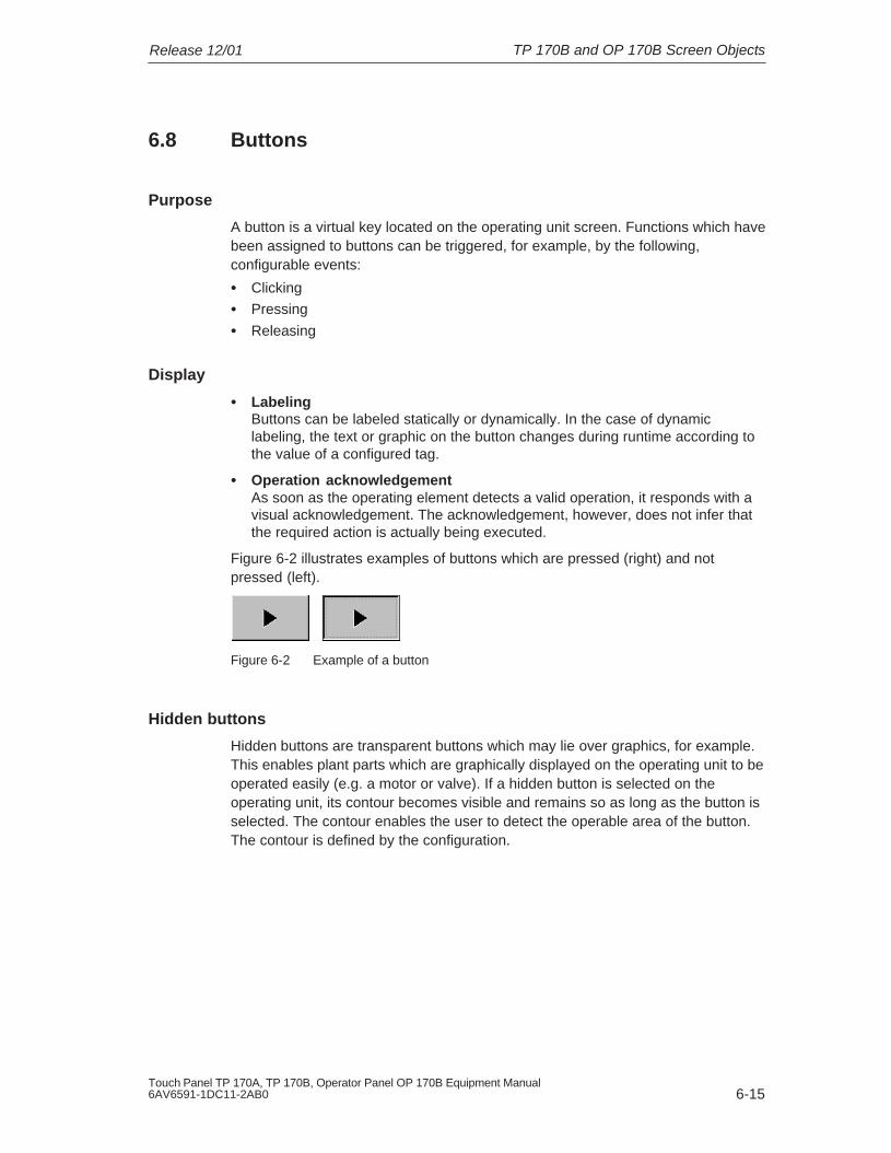
TP 170B and OP 170B Screen ObjectsRelease 12/01
6-15Touch Panel TP 170A, TP 170B, Operator Panel OP 170B Equipment Manual6AV6591-1DC11-2AB0
6.8 Buttons
Purpose
A button is a virtual key located on the operating unit screen. Functions which havebeen assigned to buttons can be triggered, for example, by the following,configurable events:
� Clicking
� Pressing
� Releasing
Display
� Labeling Buttons can be labeled statically or dynamically. In the case of dynamiclabeling, the text or graphic on the button changes during runtime according tothe value of a configured tag.
� Operation acknowledgement As soon as the operating element detects a valid operation, it responds with avisual acknowledgement. The acknowledgement, however, does not infer thatthe required action is actually being executed.
Figure 6-2 illustrates examples of buttons which are pressed (right) and notpressed (left).
Figure 6-2 Example of a button
Hidden buttons
Hidden buttons are transparent buttons which may lie over graphics, for example.This enables plant parts which are graphically displayed on the operating unit to beoperated easily (e.g. a motor or valve). If a hidden button is selected on theoperating unit, its contour becomes visible and remains so as long as the button isselected. The contour enables the user to detect the operable area of the button.The contour is defined by the configuration.

TP 170B and OP 170B Screen Objects Release 12/01
6-16Touch Panel TP 170A, TP 170B, Operator Panel OP 170B Equipment Manual
6AV6591-1DC11-2AB0
Operation
Proceed as follows to operate a button:
� OP 170B:
– Select the required button, e.g. using a cursor key.(e.g.)
– Press either the Enter key or the Spacebar.or
� TP 170B:
Touch the button on the touch screen.
Note
Click
In the case of a button, a function is triggered when the pressed button is releasedwithin the contours of the button.
If the button is pressed using the mouse button or finger (when using touchpanels) but moved outside the contour before releasing, the operating unit doesnot interpret the action as a click event. The action is not executed.
Release
In the case of a button, a function is triggered when the pressed button isreleased.
If the button is pressed using the mouse button or finger (when using touchpanels) but moved outside, the function is triggered when the function is released.
Press
In the case of a button, a function is triggered as soon as the button is pressed.
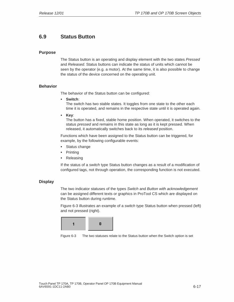
TP 170B and OP 170B Screen ObjectsRelease 12/01
6-17Touch Panel TP 170A, TP 170B, Operator Panel OP 170B Equipment Manual6AV6591-1DC11-2AB0
6.9 Status Button
Purpose
The Status button is an operating and display element with the two states Pressedand Released. Status buttons can indicate the status of units which cannot beseen by the operator (e.g. a motor). At the same time, it is also possible to changethe status of the device concerned on the operating unit.
Behavior
The behavior of the Status button can be configured:
� Switch: The switch has two stable states. It toggles from one state to the other eachtime it is operated, and remains in the respective state until it is operated again.
� Key: The button has a fixed, stable home position. When operated, it switches to thestatus pressed and remains in this state as long as it is kept pressed. Whenreleased, it automatically switches back to its released position.
Functions which have been assigned to the Status button can be triggered, forexample, by the following configurable events:
� Status change
� Printing
� Releasing
If the status of a switch type Status button changes as a result of a modification ofconfigured tags, not through operation, the corresponding function is not executed.
Display
The two indicator statuses of the types Switch and Button with acknowledgementcan be assigned different texts or graphics in ProTool CS which are displayed onthe Status button during runtime.
Figure 6-3 illustrates an example of a switch type Status button when pressed (left)and not pressed (right).
Figure 6-3 The two statuses relate to the Status button when the Switch option is set

TP 170B and OP 170B Screen Objects Release 12/01
6-18Touch Panel TP 170A, TP 170B, Operator Panel OP 170B Equipment Manual
6AV6591-1DC11-2AB0
Operation
Proceed as follows to operate a Status button:
� OP 170B:
– Select the Status button e.g. using a cursor key.(e.g.)
– Press either the Enter key or the Spacebar.or
� TP 170B:
Touch the Status button on the touch screen.
Note
Release
In the case of a button, a function is triggered when the pressed button isreleased.
If the button is pressed using the mouse button or finger (when using touchpanels) but moved outside, the function is triggered when the function is released.
Press
In the case of a button, a function is triggered as soon as the button is pressed.

TP 170B and OP 170B Screen ObjectsRelease 12/01
6-19Touch Panel TP 170A, TP 170B, Operator Panel OP 170B Equipment Manual6AV6591-1DC11-2AB0
6.10 Switch
Purpose
A switch serves for the input and output of a binary status. It can only be switchedon or off. It is linked to a tag to do this. The status OFF corresponds to the value 0(a logical FALSE) of the tag linked to the switch. All tag values other than zero (alogical TRUE) are interpreted as the status ON.
Behavior
Functions which have been assigned to the switch, can be triggered, for example,by the following, configurable events:
� Change of status
� Switch on
� Switch off
If the switch status changes as a result of a modification of configured tags, notthrough operation, the corresponding function is not executed.
Display
Figure 6-4 illustrates an example of two switches with different orientation.
Figure 6-4 Switches with different orientation
Operation
Proceed as follows to operate a switch:
� OP 170B:
– Select the required button e.g. using a cursor key.(e.g.)
– Press either the Enter key or the Spacebar.or
� TP 170B:
Slide the sliding lever to the required position or double-click on the object.The switch moves to the new position.

TP 170B and OP 170B Screen Objects Release 12/01
6-20Touch Panel TP 170A, TP 170B, Operator Panel OP 170B Equipment Manual
6AV6591-1DC11-2AB0
6.11 Messages
Message categories
Messages on the operating unit indicate events and statuses related to controlprocesses. The operating unit differentiates between the following messagecategories:
� Event messagesindicate a status in the process, for example, Motor ON. Event messages areconfigured.
� Alarm messagesindicate an equipment failure, for example, Motor temperature too high.Alarm messages are configured. Alarm messages must be acknowledged dueto their critical nature.
� HMI system messagesare triggered by the operating unit. They are not configured. System messagesindicate, for example, incorrect operations or communication faults. A selectionof important system messages is provided in Appendix C.
� SIMATIC diagnostic eventsprovide information on the status of the SIMATIC S7 and SIMOTION. They arenot configured in the ProTool CS configuration software. Refer to the S7manual for the error number indicated on the operating unit to determine thecause of the error.
Acknowledging alarm messagesAlarm messages must be acknowledged due to their importance. Thiscan be done manually on the operating unit or automatically by the PLC.The message indicator depicted continues to be flash as long asunacknowledged alarm messages are still present on the operating unitwhen this feature has been configured.
In order to acknowledge alarm messages on the OP 170B manually,press the key depicted on the right. The message must not have beenselected. The LED integrated in the key lights up when unacknowledgedmessages are present.
If several messages are displayed at the same time and the user acknowledgesalarm messages, the acknowledgement acts in hierarchical sequence on thevarious message displays:
1. Message display with focus
2. Alarm window
3. Message line
4. Message display in basic screen

TP 170B and OP 170B Screen ObjectsRelease 12/01
6-21Touch Panel TP 170A, TP 170B, Operator Panel OP 170B Equipment Manual6AV6591-1DC11-2AB0
When configuring messages, it is possible to define whether the operator mustacknowledge each message individually or whether the acknowledgement is validfor a group of messages (group acknowledgement). The use of groupacknowledgement in respect of messages is particularly useful when they relate tothe same cause, e.g. the messages for the first-up fault and the follow-up faults.
Buffering messages
All message events (arrived, departed, acknowledged) are stored in an internalvolatile buffer.
Display messages
The events stored in the message buffer can be displayed according to differentcriteria. The following predefined objects are available for display purposes:
� Message line (refer to Page 6-24)
� Message window (refer to Page 6-24)
� Message page (refer to Page 6-26)
� Message buffer (refer to Page 6-27)
� Message view– Message display with full functionality (refer to Page 6-28)
– Single message display with restricted functionality (refer to Page 6-30)
Deleting messages
All message events concerning event and alarm messages are automaticallystored in the message buffer. There are two methods of deleting message eventsfrom the message buffer:
� Automatic deletion on buffer overflowWhen the message buffer is no longer capable of accepting new messageevents, the operating unit automatically deletes a number of message eventsuntil the configured remaining buffer capacity is reached. In this case, the oldestmessage events are deleted first.
� Deletion by operating the operating unitIn order that messages can be deleted manually from the message buffer, thefunction Delete_message_buffer must be defined in the configuration e.g. linkedto a button or function key. In this way, the following message categories canbe selected for deletion according to the configuration:
– All messages
– Alarm messages
– Event messages
– HMI system messages
– SIMATIC diagnostic events

TP 170B and OP 170B Screen Objects Release 12/01
6-22Touch Panel TP 170A, TP 170B, Operator Panel OP 170B Equipment Manual
6AV6591-1DC11-2AB0
Print messages
When correspondingly configured, event messages can be printed out directlywhen the message events Arrived and Departed occur, and also alarm messageswhen the event Acknowledged occurs. System messages are not logged.
Information on setting printer parameters is provided in Chapter 8-13.
6.11.1 ALARM_S
Definition
ALARM_S is a message number procedure. The message identification numbersare assigned automatically by the configuration in STEP 7 or SIMOTION SCOUT.The unique assignment of the message text is made according to these numbers.The advantage here is that the message texts can be used on various operatingunits but only need to be entered once.
If a fault occurs, the operating unit receives the message by means of themessage number. The associated message is determined and issued according tothe number.
In addition to the message status (arrived, departed, acknowledged), the PLC alsostores time. This information is retained even after the message has been sent, sothat individual network components (e.g. operating units) can log on later and beupdated.
Configuring ALARM_S messages
ALARM_S messages are not configured in ProTool CS but in STEP 7, e.g.for S7-300/400-CPUs or in SIMOTION SCOUT. The display of ALARM_Smessages can only be configured when a SIMATIC S7 PLC is used and theProTool CS configuration software has been integrated in STEP 7.
During the configuration, it is useful to define the time of occurrence of a messagein milliseconds.
Detailed information on the configuration of ALARM_S messages is available in theProAgent/MP and ProAgent/PC user guides.
Restarting S7 CPUs
Depending on the hardware configuration of the CPUs, it is possible that undercertain circumstances all queued ALARM_S messages will be deleted when S7CPUs are restarted. Older stocks of S7-300 CPUs cannot inform the operatingunits involved of the restart. The result of this is that messages are indicated onthe operating unit as being queued although the CPU has already deleted them.

TP 170B and OP 170B Screen ObjectsRelease 12/01
6-23Touch Panel TP 170A, TP 170B, Operator Panel OP 170B Equipment Manual6AV6591-1DC11-2AB0
Remedy:Disconnect the connection between the operating unit and CPU and thenreconnect them again. Use the function e.g. Connect_Disconnect_PLC.

TP 170B and OP 170B Screen Objects Release 12/01
6-24Touch Panel TP 170A, TP 170B, Operator Panel OP 170B Equipment Manual
6AV6591-1DC11-2AB0
6.11.2 Message line
Purpose
When a message line has been configured it is always displayed, regardless of thescreen selected. The message line displays the last alarm or event messagereceived. The message line is a permanent feature on the operating unit andalways displays the current message. If a separate window has been configuredfor alarm messages, the message line only receives the current event message.
Display priorities
Alarm messages always have priority over event messages. If no alarm messagesare present or they have all been acknowledged, event messages are displayed.
6.11.3 Message window
Purpose
The message window displays all messages in the respective message categorieswhich are queued or need to be acknowledged.
It is possible to configure how the alarm messages are sorted. It is also possible toselect whether the latest or oldest message is displayed first.
Alarm messages
If one of the display modes Window/Window, Window/Line or Window/Off isconfigured, the message window for alarm messages opens automatically as soonas an alarm message arrives. Figure 6-5 illustrates an example.
Text�� ������� ���
� �������� �������� ������� �������� ���� ����
AM Window
Figure 6-5 Alarm window (example of TP 170 B)

TP 170B and OP 170B Screen ObjectsRelease 12/01
6-25Touch Panel TP 170A, TP 170B, Operator Panel OP 170B Equipment Manual6AV6591-1DC11-2AB0
Significance of the buttons
Call Help text Use this button to call in the help text configured for theselected message.
Edit Message Use this button to trigger the function assigned to theEdit Message event for the selected message.
Acknowledge alarm messages Use this button to acknowledge unacknowledged alarmmessages.
Event messages
In order to be able to open the event message window by means of the mouse orkeyboard the function Display_event_message_window, for example, must belinked to a function key or button in the project.
System messages
The message window for system messages opens automatically as soon as asystem message arrives. The window is closed automatically after the configured
duration of display has expired or by pressing ESC or .

TP 170B and OP 170B Screen Objects Release 12/01
6-26Touch Panel TP 170A, TP 170B, Operator Panel OP 170B Equipment Manual
6AV6591-1DC11-2AB0
6.11.4 Message page
Purpose
The message page displays all messages allocated a time stamp. It is alsopossible to select whether the latest or oldest message is displayed first. Openmessage pages are constantly updated.
Structure
In order to have access to the message page for event messages and/or alarmmessages, the following functions must have been configured:
� for event messages: Display_event_message_page
� for alarm messages: Display_alarm_message_page
Figure 6-6 illustrates an example of the message page for alarm messages.
AM Page
�� �������� �� !��!�� "#
������� ���
Figure 6-6 Alarm message page (example of TP 170 B)
Information on the significance of the buttons is provided on Page 6-24.
In the case of the TP 170B, the queued alarm messages can also be selected viathe message indicator.
It is possible to configure how the alarm messages are sorted.

TP 170B and OP 170B Screen ObjectsRelease 12/01
6-27Touch Panel TP 170A, TP 170B, Operator Panel OP 170B Equipment Manual6AV6591-1DC11-2AB0
6.11.5 Message buffer
Purpose
The message buffer displays all message events allocated a time stamp. It is alsopossible to select whether the latest or oldest message is displayed first. Openmessage buffers are constantly updated.
Structure
In order to have access to the message buffer for event messages and/or alarmmessages, the following functions must have been configured:
� for event messages: Delete_event_message_buffer
� for alarm messages: Delete_alarm_message_buffer
Figure 6-7 illustrates an example alarm message buffer.
AM Buffer
�� �������� �� !��!�� "
������� ���
�� ����$�� �� !��!�� %"&#
������� ���
Figure 6-7 Alarm message buffer (example of TP 170B)
Information on the significance of the buttons is provided on Page 6-24.
The message buffer is organized so that in the case of a buffer overflow the oldestmessage events are overwritten (”FIFO buffer”). It is also possible to delete theentire buffer or specific message categories from time to time(Delete_message_buffer) function. This relieves the system load and provides aclearer overview of the message buffer.
It is possible to configure how the alarm messages are sorted.
The column width can be modified by means of touch operation. The OP 170B canbe adapted by pressing Ctrl and +.

TP 170B and OP 170B Screen Objects Release 12/01
6-28Touch Panel TP 170A, TP 170B, Operator Panel OP 170B Equipment Manual
6AV6591-1DC11-2AB0
6.11.6 Message display
Purpose
Certain views are defined in the message indicator for messages which arequeued or still to be acknowledged or for message events in the message buffer.Various filter criteria are available in ProTool CS for this purpose.
Filter criteria include:
� Message number
� Time
� Message states
� Message text
� Date
� Category name
� Acknowledgment group
� Diagnostics capability
� PLC
The attribute PLC is only useful when more than one PLC is configured as sourceof the message. In this way, the precise fault location can be displayed withdate/time of the message event.
Structure
Figure 6-8 illustrates an example of a message display. This display can also beused to acknowledge alarm messages.
Figure 6-8 Message display (example of the TP 170 B)

TP 170B and OP 170B Screen ObjectsRelease 12/01
6-29Touch Panel TP 170A, TP 170B, Operator Panel OP 170B Equipment Manual6AV6591-1DC11-2AB0
Significance of the buttons
Call Help text
Use this button to call in the help text configured for theselected message.
Edit Message
Use this button to trigger the function assigned to theEdit Message event for the selected message.
Acknowledge messages
Use this button to acknowledge unacknowledged alarmmessages.
Message categories
In order to be able to distinguish between the different message categories, theyare marked in the first column of the message display:
! Alarm messages
Empty Event messages
$ HMI System Messages
S7 SIMATIC diagnostic events
Alarm_S messages are displayed either as alarm messages or event messages.SFM messages (System Fault Messages) are displayed as alarm messages.

TP 170B and OP 170B Screen Objects Release 12/01
6-30Touch Panel TP 170A, TP 170B, Operator Panel OP 170B Equipment Manual
6AV6591-1DC11-2AB0
6.11.7 Single message display
Purpose
A single message display provides a subset of the functionality of a messagedisplay (Page 6-28). This provides a simple method with which, for example, tocreate a message line to display event and system messages in a screen.
Structure
The single message display cannot be operated. The figure below provides anexample of a single message display with the following columns configured:
� Date
� Time
� Message number
� Message states
� Message text
12.12.99 14:27:06 110001 K Change to operating status ’online’
12.12.99 14:27:07 140001 K Connection discontinued: Station 2, Rack 0, Slot 0

TP 170B and OP 170B Screen ObjectsRelease 12/01
6-31Touch Panel TP 170A, TP 170B, Operator Panel OP 170B Equipment Manual6AV6591-1DC11-2AB0
6.12 Bar Graphs
Purpose
Bar graphs present a value in the form of a rectangular area. The operating unitthus provides a clear indication of how far the current value is from the limit values,or if a setpoint value has been reached, at a glance. Bar graphs can be used todisplay fill levels or quantities, for example.
Display
It is possible to configure minimum and maximum values and the direction bargraph moves by increasing the tag value:
Figure 6-9 depicts the various states of a horizontal bar graph:
1. Value drops below the minimum value configured
2. Value lies within the configured display range
3. Value exceeds the maximum value configured
4. Value lies within the configured limit range
Figure 6-9 Different bar states

TP 170B and OP 170B Screen Objects Release 12/01
6-32Touch Panel TP 170A, TP 170B, Operator Panel OP 170B Equipment Manual
6AV6591-1DC11-2AB0
6.13 Trend View
Purpose
The trend view is a particularly clear form of displaying process data in acontinuous manner. In the case of processes that only change slowly, the trendview can visualize events that have already occurred and provides access to, andestimate of trends in the process sequence.
Configurable properties
A number of different trends can be displayed simultaneously in the trend view.The following properties are among those which can be configured for a trendgraphic:
� Trend Type: Trend curve
� Triggering: Clock trigger
� Limit values: Upper and lower limitsThe operating unit displays the points at which configured limit values arereached or exceeded by changing the color of the trend display.
� Color: Uncertain status
The uncertain status function highlights areas of the trend view in whichcommunication to the unit was interrupted and, as a result, no values could berecorded.
Read line
The readline function is used in a trend graphic to display or hide a read line whichdisplays Y-values associated to an X-value.
The read line can be activated by means of the Trend_view_read_mark_on_offfunction (default: Off). The color of the read line can be configured in the Color tabcontrol.
If the Display Value Table function is activated in the Value Table tab control, atable appears in the trend view containing the values of the trend curve displayed.
The read line can be operated by touching the screen or via the keyboard (Ctrl +Alt + Cursor Right/Left). It is also possible to configure buttons for the functionsTrend_view_read_mark_forward and Trend_view_read_mark_backward. When theread line is moved, the values in the value table (when activated) are automaticallyupdated accordingly.

TP 170B and OP 170B Screen ObjectsRelease 12/01
6-33Touch Panel TP 170A, TP 170B, Operator Panel OP 170B Equipment Manual6AV6591-1DC11-2AB0
Structure
Figure 6-10 illustrates an example of a trend view with a trend curve andconfigured buttons to navigate in the trend, read line and related value table.
Trend Tag connection Value X value
Figure 6-10 Operable trend view with read line (example)
Navigation using buttons or function keys
When correspondingly configured, the following functions may be assigned tobuttons, for example, to navigate in the trend view:
Function Function
Start_stop_trend_displayInterrupts the current updating process for the trendview until the button is pressed again.
Trend_display_back_to_beginning Scrolls back to the start of the trend recording.
Trend_display_scroll forward,Trend_display_scroll_back
Shifts the trend section half a window width to theleft/right.
Trend_display_extend, Trend_display_compress
Expands/compresses the trend view horizontally.
Trend_view_read_mark_on_off Switches the read line on or off.
Trend_view_read_mark_forward Moves the read line to the right.
Trend_view_read_mark_backward Moves the read line to the left.

TP 170B and OP 170B Screen Objects Release 12/01
6-34Touch Panel TP 170A, TP 170B, Operator Panel OP 170B Equipment Manual
6AV6591-1DC11-2AB0
Navigation using the system keys (OP 170B)
If it is possible to navigate through the project via a keyboard, use the following keycombinations to navigate in the trend view:
Keys Function
Back to start Scrolls back to the start of the trend recording.
Scroll back Scroll one screen width back.
Scroll forward Scroll one screen width forward.
Zoom section Expands the trend view horizontally.
Reduce section Compresses the size of the trend viewhorizontally.
Read lineforwards
Moves the read line to the right in the trendcurve.
Read linebackwards
Moves the read line to the left in the trend curve.
Notice
It is not possible to interrupt the updating of the trend view using the keyboard.

TP 170B and OP 170B Screen ObjectsRelease 12/01
6-35Touch Panel TP 170A, TP 170B, Operator Panel OP 170B Equipment Manual6AV6591-1DC11-2AB0
6.14 Password List
Purpose
While the system is being configured using ProTool CS, additional operatingelements can be protected against unauthorized use by means of passwords.Important parameters and settings can then only be modified by authorizedpersonnel. The password level and user name are stored with the password.
The Report_password_change function causes a system message to be issuedwhen a different password is entered on the operating unit, i.e. a new user logs on.
The Write_user_name_to_tag function is used to write the name of the usercurrently logged on into a tag of type “STRING”. If the tag is one with a PLC link,the user name also exists in the PLC and can be used for the user-dependentenabling of certain functions. User names must always be unique for theassignment. They are stored in a password file.
Password hierarchy
Hierarchically defined password levels from 0 to 9 exist for password protectionpurposes. When a password is assigned to an individual user or to a whole usergroup, the permission to execute functions at a specific level is assignedsimultaneously. If, for example, a user is assigned to password level 4, he or sheis authorized to execute functions of password levels 0 to 4.
Password level
Password level 0:This minimum password level is assigned to functions that have no, or only aminimal effect on the course of the process. In order to trigger functions assignedto Password Level 0, no password needs to be entered.
Password levels 1 to 8:Functions are assigned to levels 1 to 8 according to their increasing importance.Before triggering a function with a password level greater than 0, the operating unitrequests the corresponding password to be entered.
Password level 9Only the supervisor (system support specialist or service technician) is grantedauthorization to execute functions assigned to password level 9. The supervisor isauthorized to access all the functions on the operating unit.

TP 170B and OP 170B Screen Objects Release 12/01
6-36Touch Panel TP 170A, TP 170B, Operator Panel OP 170B Equipment Manual
6AV6591-1DC11-2AB0
Logging in on the operating unit (login)
After calling a function protected by a password, the operating unit automaticallyrequests the entry of a password. Once entered, the password need not beentered again in order to call in other functions of this password level or lower.
When correspondingly configured, it is also possible to log on via an input field forconfidential password entry. The character string entered is represented byplaceholders (*).
Logging off from the operating unit (logoff)
In order to rule out operation by unauthorized personnel, a password level greaterthan 0 should not remain active on the operating unit over too long a period oftime. The following options are available to explicitly reset passwords levels:
� Configured logout time expiresIf the operating unit is not operated within the period of time configured (logouttime), the current password level is automatically reset to 0.
� Manual logoutIf the function Logoff_user is linked to an operating element in the project, it canbe used to reset the current password level to 0.
NoteThe current password level can be reset to 0 by entering an incorrectpassword.
6.14.1 Password management
Individual users can be entered in a password list on the operating unit andassigned a password level according to their specific responsibilities. Whenprocessing the list, conclude each field entry by pressing the Enter key. Thepassword list contains all the passwords configured on the operating unit. The listis coded and stored on the operating unit, protected against a power failure.
Figure 6-11 illustrates an example of a password list with six entries.
User Password Level
Figure 6-11 Example of a password list

TP 170B and OP 170B Screen ObjectsRelease 12/01
6-37Touch Panel TP 170A, TP 170B, Operator Panel OP 170B Equipment Manual6AV6591-1DC11-2AB0
View password list
Only those passwords are displayed which have a password level equal to or lowerthan that with which the user is currently logged in. The operating unit displays thepassword list entries in alphabetic order.
Creating a password
The user can only edit the password list up to the level with which he is currentlylogged in. All passwords used in the system must be unique. It is not possible toassign identical passwords to different users. It is possible, however, to assign thesame password level to different users without any restrictions.
Deleting a password
To delete a password from the password list, overwrite the password levelassigned to it with 0.
6.14.2 Export/Import password list
Purpose
If a system includes several operating units which are accessed by the sameusers, the same passwords must be installed on each operating unit. In order thatthe password list need not be re-entered on each operating unit, it can be createdon unit and imported on other units.
Note
During an import, all currently valid passwords are overwritten. The importedpasswords become valid immediately.
If an existing user name or password is entered, the corresponding systemmessage is issued.
Condition
In order to be able to export/import password lists on the operating unit, theImport_Export_Passwords function must be linked to a button or function key, forexample. The file name of the password list to be exported/imported must bespecified as the function parameter during configuration.

TP 170B and OP 170B Screen Objects Release 12/01
6-38Touch Panel TP 170A, TP 170B, Operator Panel OP 170B Equipment Manual
6AV6591-1DC11-2AB0
Note
� The password list is coded. It cannot be edited with external tools.
� Do not export a password list directly after it has been modified. Exit the screenobject Password List after changing it and wait with the export function untilmodifications have been written in the internal Flash memory.
Action
Proceed as follows to export or import the password list:
1. Insert the CF card.
2. Deactivate the write protection on the CF card.
3. Operate the element linked to the Export_Import function.
4. Wait for the message indicating that the import or export has ended.
5. Remove the CF card.
If a fault occurs during the process, a fault message appears.
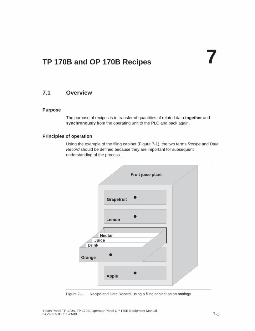
7-1Touch Panel TP 170A, TP 170B, Operator Panel OP 170B Equipment Manual6AV6591-1DC11-2AB0
TP 170B and OP 170B Recipes
7.1 Overview
Purpose
The purpose of recipes is to transfer of quantities of related data together andsynchronously from the operating unit to the PLC and back again.
Principles of operation
Using the example of the filing cabinet (Figure 7-1), the two terms Recipe and DataRecord should be defined because they are important for subsequentunderstanding of the process.
Fruit juice plant
Grapefruit
Lemon
Orange
Drink
NectarJuice
Apple
Figure 7-1 Recipe and Data Record, using a filing cabinet as an analogy
7

TP 170B and OP 170B Recipes Release 12/01
7-2Touch Panel TP 170A, TP 170B, Operator Panel OP 170B Equipment Manual
6AV6591-1DC11-2AB0
� RecipeRecipes correspond to the individual drawers of the filing cabinet illustrated (e.g.grapefruit or lemon). The reference value fields (tags) belonging to the particularrecipe are defined in each drawer. The recipes define the data structure inProTool CS. This structure cannot be modified later on the operating unit.
� Data recordData records correspond to the filing cards in the individual drawers of thecabinet (e.g. Drink, Juice and Nectar). A data record contains the values for arecipe. Data records are created, modified and deleted on the operating unit.The data records are also stored on the operating unit. This saves storagespace on the PLC.
The Import/Export function provides the additional option of using external toolsto edit exported data records e.g. Excel and then reimporting them on theoperating unit.
Example of a recipe
An example for use of a recipe is its application on a filling station of a fruit juicesystem. The same filling station is used to produce orange drink, orange juice andorange nectar. The mixing ratios are different for each product. The ingredients arealways the same.
Assume that a recipe called Mixture is created, which has the following datastructure:
Tag Name
Var_2 l orange
Var_3 l water
Var_4 kg sugar
Var_5 g flavor
The designations l Orange, g Aroma etc. of the tags are the so called entrynames. The entry names represent the ingredients and also appear on theoperating unit. In this way, for example, the tag Var_2 can be identified as the tagdesignating the mixture component Orange.
The data records contain the values for the different drink types. The data records
may appear as follows, for instance:
Orange drink Orange juice Orange nectar
l orange 90 l orange 95 l orange 70
l water 10 l water 5 l water 30
kg sugar 1.5 kg sugar 0.5 kg sugar 1.5
g flavor 200 g flavor 100 g flavor 400

TP 170B and OP 170B RecipesRelease 12/01
7-3Touch Panel TP 170A, TP 170B, Operator Panel OP 170B Equipment Manual6AV6591-1DC11-2AB0
7.2 Use of Recipes
The following section contains a description of the data flow for recipes and threeapplication scenarios illustrating the use of recipes in the form of short, practicalexamples. They should provide a top level overview of the possibilities for usingrecipes:
� The first scenario illustrates a recipe configuration in which the data entered isnot immediately transferred to the PLC. This configuration is used, for example,when it is necessary to enter data on the operating unit without interfering withan active process.
� In the second scenario, data is immediately transferred to the PLC. Thisconfiguration can be used, for example, to start up a machine and correct thepositioning data online.
� The third scenario implements data record functions in order to controlproduction automatically via a job list.
7.2.1 Data flow for recipes
The diagram illustrates various possibilities concerning data flow when usingrecipes. The data flow between the active components operating unit (A), PLC (B)and external data medium (C) is dependent on the configuration of the recipe andthe functions used.
External data medium
Storage medium Display
PLC
Recipe_1
Recipe_2
Recipe_n
Figure 7-2 Data flow for recipes

TP 170B and OP 170B Recipes Release 12/01
7-4Touch Panel TP 170A, TP 170B, Operator Panel OP 170B Equipment Manual
6AV6591-1DC11-2AB0
The operating unit (A) stores the recipe data records on a storage medium, e.g.Flash. The recipe data record can be edited in a recipe view or recipe screen onthe operating unit display:
� A new data record can be entered and can then, for example, be stored (2) onthe storage medium and transferred (3) to the PLC (B).
� The data record can be exported to an external data medium (C), e.g. a PC.The data record is saved in CSV format, regardless of the recipe. This file canthen be loaded and edited in MS Excel, for example.
� A data record can be loaded (2) from the operating unit storage medium orimport (1) it as a *.CSV file from an external data medium.
A recipe data record can also be transferred (4) directly from the storage mediumto the PLC or loaded from the PLC to the storage medium. In the same way, arecipe in the display can be transferred (3) to the PLC or loaded from it.
7.2.2 Application examples
Scenario 1: Enter data record
Production data must be entered on operating unit (A) without interfering in theactive process. The production data should not be transferred to the PLC (B).
External data medium
Recipe_1Recipe_2
Recipe_n
Storage medium Display
PLC
Figure 7-3 Process
Enter the production data in the recipe view or recipe screen, assign a data recordname and save the new data record on the operating unit storage medium.

TP 170B and OP 170B RecipesRelease 12/01
7-5Touch Panel TP 170A, TP 170B, Operator Panel OP 170B Equipment Manual6AV6591-1DC11-2AB0
Scenario 2: Automatic production process
Production should be automated by means of a job list. The production data shouldbe transferred directly to the PLC (B) either from the data medium in the operatingunit (A) or from an external data medium (C). It is not necessary to show it in thedisplay.
External data medium
Recipe_1Recipe_2
Recipe_n
Storage medium Display
PLC
Figure 7-4 Process
Production can be controlled via PLC jobs which automatically transfer theproduction data records to the PLC.
The automatic production process can be realized using the data record functionsprovided: The Import_Data_Records function loads data records from a *.CSV fileto the data medium. The Data_Record_DAT_to_PLC function transfers a datarecord from the data medium to the PLC.

TP 170B and OP 170B Recipes Release 12/01
7-6Touch Panel TP 170A, TP 170B, Operator Panel OP 170B Equipment Manual
6AV6591-1DC11-2AB0
7.3 Recipe Configuration
Basic procedure
The basic steps to configuring a recipe are listed below:
1. Define the structure of the recipe:Assign tags to the recipe structure. These tags are assigned entries from thedata records.
Define a name for the recipe. This name is used to select the recipe in theproject and on the operating unit.
2. Set recipe tag propertiesThe following options can be configured in ProTool CS:
– Synchronize tags This option defines that the data from a data record has been read from thePLC or data medium and written in the tag or read from the tags configuredfor the recipe. This establishes a connection between the tags configured inthe recipe and the tags in the screens. When a data record is loaded, thevalues are written to the tags used in the screens.
– Tags offline If this option is also activated, the values entered are only stored in the tags,and not transferred to the PLC. Otherwise, values entered are transferreddirectly to the PLC.
3. Define data record storage medium operating unitThe data storage location for data records can be configured. The followingsettings are possible:
– Internal Flash
– Memory card (CF card)
Caution
Cyclical writing access is not permitted for the internal Flash memory because itreduces the service life of the Flash memory and thus the service life of the unit.Use an external memory card instead.
4. Set download synchronization
It is possible to configure whether the data records are downloaded to the PLCwith or without synchronization.
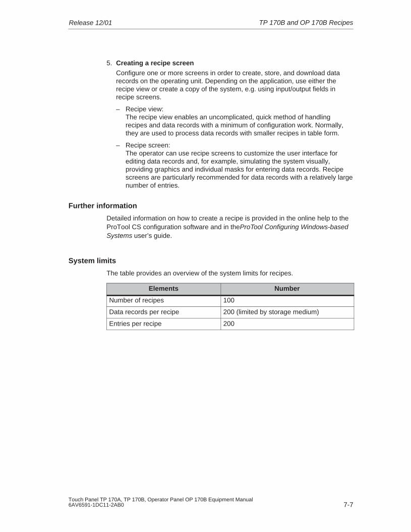
TP 170B and OP 170B RecipesRelease 12/01
7-7Touch Panel TP 170A, TP 170B, Operator Panel OP 170B Equipment Manual6AV6591-1DC11-2AB0
5. Creating a recipe screenConfigure one or more screens in order to create, store, and download datarecords on the operating unit. Depending on the application, use either therecipe view or create a copy of the system, e.g. using input/output fields inrecipe screens.
– Recipe view: The recipe view enables an uncomplicated, quick method of handlingrecipes and data records with a minimum of configuration work. Normally,they are used to process data records with smaller recipes in table form.
– Recipe screen: The operator can use recipe screens to customize the user interface forediting data records and, for example, simulating the system visually,providing graphics and individual masks for entering data records. Recipescreens are particularly recommended for data records with a relatively largenumber of entries.
Further information
Detailed information on how to create a recipe is provided in the online help to theProTool CS configuration software and in theProTool Configuring Windows-basedSystems user’s guide.
System limits
The table provides an overview of the system limits for recipes.
Elements Number
Number of recipes 100
Data records per recipe 200 (limited by storage medium)
Entries per recipe 200

TP 170B and OP 170B Recipes Release 12/01
7-8Touch Panel TP 170A, TP 170B, Operator Panel OP 170B Equipment Manual
6AV6591-1DC11-2AB0
Memory requirements for data records
The memory requirements per recipe (in kByte) is calculated from the threesummands D1 + D2 + D3.
The following applies:
D1 = [(no. of entries x 9 + tag name total length ) + 4] : 1024D2 = [(no. of data records x 12) + 4] : 1024D3 = [no. of data records x (data record length + N) + 4] : 1024
D1, D2 and D3 are rounded up to the next whole number.
A data record length is the sum of all the tag lengths configured for the data recordin bytes. For example, a tag of the type FLOAT has a length of 4 byte.
The tag name total length is the sum of the length of all the tag names which areused in the entries.
The following applies for N:
Data record name < 13 characters: N = 12Data record name > 12 characters: N = 40
Notice
The internal Flash memory has a maximum storage capacity of 32 kByte.
Note:In the interest of optimizing the service life of the unit and achieving a betterperformance, use an external memory card to store data records.

TP 170B and OP 170B RecipesRelease 12/01
7-9Touch Panel TP 170A, TP 170B, Operator Panel OP 170B Equipment Manual6AV6591-1DC11-2AB0
7.4 Editing Data Records
In this chapter
This chapter provides information on how to edit data records on the operating unit.The following information is included:
� Layout of the recipe view (Page 7-10)
� Displaying data records (Page 7-13)
� Creating new data records (Page 7-13)
� Copying data records (Page 7-14)
� Modifying data records (Page 7-15)
� Copying data records by selecting a data record name (Page 7-15)
� Renaming data records (Page 7-16)
� Deleting data records (Page 7-16)
� Reading data records from the PLC (Page 7-17)
� Downloading data records to the PLC (Page 7-17)
� Synchronizing a data record (Page 7-18)
� Editing data records in recipe screens (Page 7-18)
� Functions and PLC jobs (Page 7-21)
� Exporting/Importing data records (Page 7-22)
� Exporting, editing and importing data records (Page 7-24)
� Reaction to changing the recipe structure (Page 7-26)
Methods
Data records can be edited on the operating unit in tables or screens:
� Tabular editingThe recipe view is available for the tabular editing of data records (Page 7-10).The recipe view enables recipes and data records to be handled in anuncomplicated, quick way.
Normally, they are used to process data records with smaller recipes offline.Values entered on the operating unit are not directly transferred to the PLCwhen entered.
� Editing in recipe screensThe project engineer can use recipe screens (Page 7-18) to customize the userinterface for editing data records and, for example, simulating the systemvisually, providing graphics and individual masks for entering data records.
This method is typically used for processing medium and large data recordsoffline in the recipe view. The values entered on the operating unit are onlysaved in the tags, not transferred to the PLC directly on input.

TP 170B and OP 170B Recipes Release 12/01
7-10Touch Panel TP 170A, TP 170B, Operator Panel OP 170B Equipment Manual
6AV6591-1DC11-2AB0
7.4.1 Recipe view
Purpose
The recipe view is typically used to edit recipe data records in tabular form. Thisprovides an uncomplicated method of displaying, creating, copying, modifying,deleting and downloading data records on the operating unit.
All descriptions on editing data records provided in this Chapter 7.4.1 relates purelyto the use of the recipe view. Information on editing data records in recipe screensis provided from Page 7-18.
Display
Figure 7-5 illustrates an example of the layout of the recipe view. Some of theoperating and display elements can be configured so that they are faded out on theoperating unit.
Figure 7-5 Layout of the recipe view (example)

TP 170B and OP 170B RecipesRelease 12/01
7-11Touch Panel TP 170A, TP 170B, Operator Panel OP 170B Equipment Manual6AV6591-1DC11-2AB0
Significance of the operating and display elements
No. Function
Select recipeIf the corresponding function is enabled in ProTool CS, it is possible toselect a configured recipe in this selection field. The number of theselected recipe is displayed to the right of the selection field. Thisnumber is only relevant during the configuration. They cannot bemodified on the operating unit.
Select data recordAs soon as a recipe has been selected, the data records available aredisplayed in this field. In addition, the data record number is displayed tothe right. The number field only becomes active when the input of a datarecord number is permitted, e.g. after changing the data record numberor creating a new data record.
View/Edit entriesThis table contains all the entries which are configured in the selecteddata record. Sorting complies to the configured sequence. Theright-hand column displays the associated values.
The entry names cannot be edited on the operating unit.
Create new data recordThis button initiates the creation of a new data record. Thesetpoint values are predefined with default values configuredas start values for the respective tags.
Key combinations:
Save data recordThis button is used to save the current values of the daterecord displayed on the operating unit data medium. Thememory location is defined in ProTool CS.
The data record is stored under the currently defined nameand number.
Key combinations:
Delete data record
This button is used to delete the data record currentlydisplayed for the defined recipe from the operating unit datamedium.
Key combinations:
Read data record from the PLCThis button is used to read the data record related to thecurrently set recipe from the PLC and display the values onthe operating unit.
Key combinations:

TP 170B and OP 170B Recipes Release 12/01
7-12Touch Panel TP 170A, TP 170B, Operator Panel OP 170B Equipment Manual
6AV6591-1DC11-2AB0
FunctionNo.
Write data record in the PLC
This button is used to write the current data record values inthe PLC.
Key combinations:
Status bar
The operating unit displays the status of the current operation in thisline, e.g. Downloading.
Other buttons
The following buttons are only visible when they have been correspondinglyconfigured by means of an attribute in the recipe view:
Synchronize
This button is used to synchronize the data in a recipe view with theassociated tag. Modified values are written in the corresponding tags inthe table of a recipe view. All the values are then written from the tags tothe recipe view and updated in the table. This ensures consistencybetween the recipe view and tags.
The button is only enabled for use in the case or recipes withsynchronized tags.
Key combinations: =
Save data record as
After pressing this button, a dialog appears in which to select an existingdata record name and modify it. After confirming the dialog, the currentvalues are stored under the new name.
Key combinations:*
Note
� If the two options Synchronize Tags and Tags Offline are activated in theproject, the values from the table are applied when values in the tables andscreens are changed simultaneously.
� If the data record currently being edited in the recipe view is changed in thebackground (e.g. by means of a PLC job), the recipe view is not automaticallyupdated.

TP 170B and OP 170B RecipesRelease 12/01
7-13Touch Panel TP 170A, TP 170B, Operator Panel OP 170B Equipment Manual6AV6591-1DC11-2AB0
Notes on operation using the recipe views
� Quick selection of recipes and data records
When the selection field is opened up, enter the first letter of the recipe or datarecord to be selected to access the relevant area of long lists, thus speeding upthe selection procedure.
� Edit entriesIf the value marked in the recipe view is to be modified, it is initially deleted bypressing one of the alphanumeric keys. This occurs with regard to all listelements in Windows. In order to prevent this, proceed as follows:
– After selecting the value to be changed, press the Enter key.
– Move the text cursor to the position to be changed using the cursor keys.
– Insert the modifications.
– Confirm the changes, e.g. by pressing the Enter key.
Displaying data records
Proceed as follows to display data records on the operating unit data medium:
Step Action
1 Select recipe Step 1 is only possible when recipe selection has beenconfigured.
� Select the selection field for the configured recipes (Position 1 in the figure on Page 7-10).
� Open the selection field and mark the required recipe in theopened selection list.
� Confirm the selection.
2 Select data record � Select the selection field for the existing data records(Position 2 in the figure on Page 7-10).
� Open the selection field and mark the required data record inthe opened selection list.
� Confirm the selection.The selected data record is loaded. The configured entriesare displayed in table form with name and setpoint value.
Creating new data records
Proceed as follows to create new data records on the operating unit:
Step Action
1 Select recipe � Select the required recipe as described in Displaying datarecords Step 1 on Page 7-13.
2 Create data record � Press the key depicted on the left.
The data record name must then be entered. The smallestpossible number is suggested as the number for the datarecord. The entries in the table are assigned the configuredstart values.
2 � Press the key depicted on the left.
The data record name must then be entered. The smallestpossible number is suggested as the number for the datarecord. The entries in the table are assigned the configuredstart values.

TP 170B and OP 170B Recipes Release 12/01
7-14Touch Panel TP 170A, TP 170B, Operator Panel OP 170B Equipment Manual
6AV6591-1DC11-2AB0
ActionStep
3 Enter data recordname
� Enter a new data record name in the selection field for datarecords (Position 2 in the figure on Page 7-10).
� After entering the data record name, the next free datarecord number is automatically entered on the right. Thisnumber can be changed, if necessary.
4 Change values � Enter a setpoint value for each entry configured in the table(Position 3 in the figure on Page 7-10).
5 Save data record � Press the key depicted on the left.
The new data record is written on the data medium.
The operating unit responds with a system message if thename or number entered already exist.
5 � Press the key depicted on the left.
The new data record is written on the data medium.
The operating unit responds with a system message if thename or number entered already exist.
Storage location for new data records
The data storage location for the new data record can be configured. The followingsettings are possible:
� Internal Flash memory
� Memory card (CF card)
Copying data records
In order to copy data records, save them under new names. Proceed as follows:
Step Action
1 Select recipe anddata record
� Select the required recipe and the data record to be copiedas described in Displaying data records , Steps 1 and 2 onPage 7-13.
2 Enter data recordname
� Enter a new data record name in the selection field for datarecords (Position 2 in the figure on Page 7-10).
� After entering the data record name, the next free datarecord number is automatically entered on the right. Thisnumber can be changed, if necessary.
3 Save data record � Press the key depicted on the left.
The new data record is written on the data medium.
The operating unit responds with a system message if thename or number entered already exist.
3 � Press the key depicted on the left.
The new data record is written on the data medium.
The operating unit responds with a system message if thename or number entered already exist.
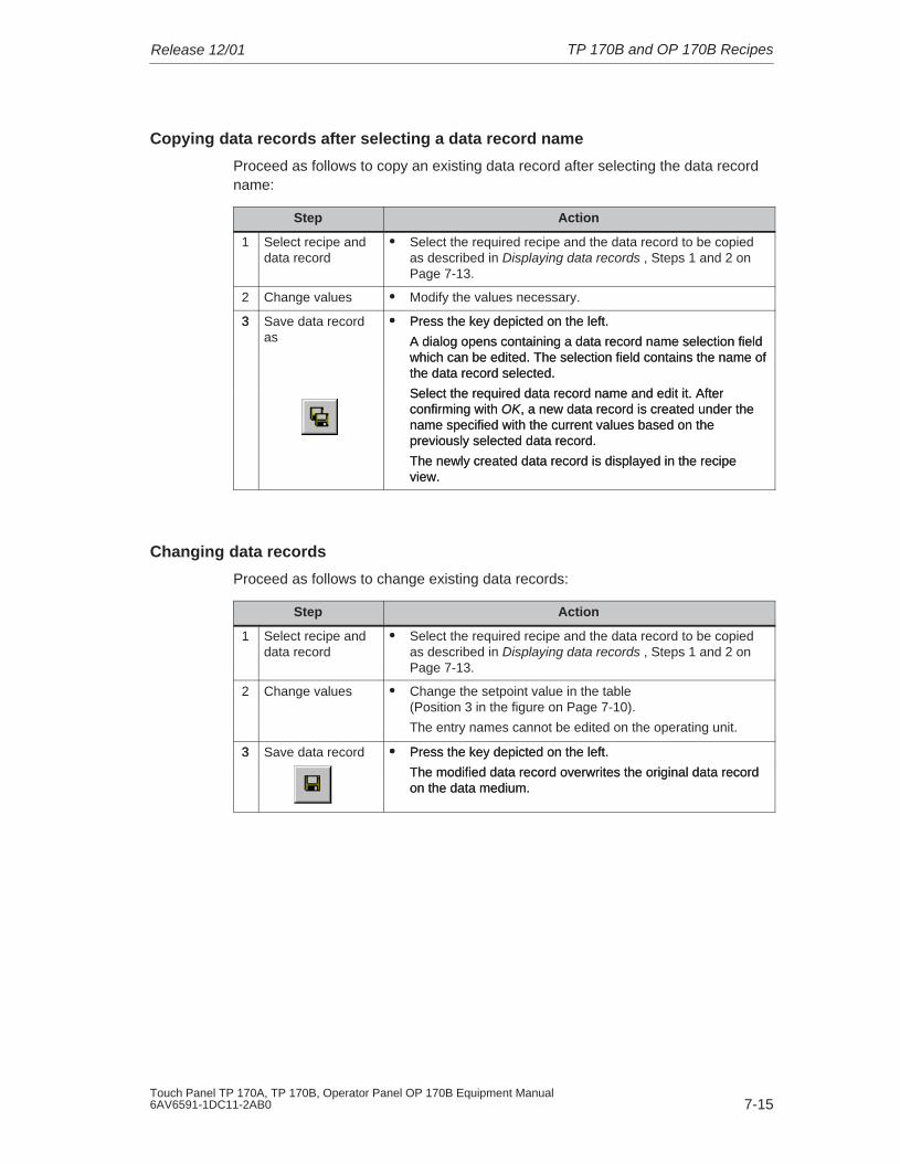
TP 170B and OP 170B RecipesRelease 12/01
7-15Touch Panel TP 170A, TP 170B, Operator Panel OP 170B Equipment Manual6AV6591-1DC11-2AB0
Copying data records after selecting a data record name
Proceed as follows to copy an existing data record after selecting the data recordname:
Step Action
1 Select recipe anddata record
� Select the required recipe and the data record to be copiedas described in Displaying data records , Steps 1 and 2 onPage 7-13.
2 Change values � Modify the values necessary.
3 Save data recordas
� Press the key depicted on the left.
A dialog opens containing a data record name selection fieldwhich can be edited. The selection field contains the name ofthe data record selected.
Select the required data record name and edit it. Afterconfirming with OK, a new data record is created under thename specified with the current values based on thepreviously selected data record.
The newly created data record is displayed in the recipeview.
3 � Press the key depicted on the left.
A dialog opens containing a data record name selection fieldwhich can be edited. The selection field contains the name ofthe data record selected.
Select the required data record name and edit it. Afterconfirming with OK, a new data record is created under thename specified with the current values based on thepreviously selected data record.
The newly created data record is displayed in the recipeview.
Changing data records
Proceed as follows to change existing data records:
Step Action
1 Select recipe anddata record
� Select the required recipe and the data record to be copiedas described in Displaying data records , Steps 1 and 2 onPage 7-13.
2 Change values � Change the setpoint value in the table (Position 3 in the figure on Page 7-10).
The entry names cannot be edited on the operating unit.
3 Save data record � Press the key depicted on the left.
The modified data record overwrites the original data recordon the data medium.
3 � Press the key depicted on the left.
The modified data record overwrites the original data recordon the data medium.

TP 170B and OP 170B Recipes Release 12/01
7-16Touch Panel TP 170A, TP 170B, Operator Panel OP 170B Equipment Manual
6AV6591-1DC11-2AB0
Notice
If large-scale modifications have been carried out in recipes in ProTool CS and,after downloading the modified project, the data records on the operating unit datamedium deviate a great deal from the original recipe structure, it is recommendedto reorganize the data medium:
� export the data records of all the recipes (refer to Page 7-22).
� delete the data records using the function Delete_Data_Record_Memory.
� import the data records using the function Import_Data_Records.
In this way, all the tags no longer used are deleted.
Renaming data records
Proceed as follows to rename existing data records:
Step Action
1 Select recipe anddata record
� Select the required recipe and the data record to be copiedas described in Displaying data records, Steps 1 and 2 onPage 7-13.
2 Enter data recordname
� Enter a new data record name in the selection field for datarecords (Position 2 in the figure on Page 7-10).
� After entering the data record name, the next free datarecord number is automatically entered on the right. Resetthis number to its original value.
3 Save data record � Press the key depicted on the left.
The modified data record is written on the data medium.
The operating unit responds with a system message if thename or number entered already exist.
3 � Press the key depicted on the left.
The modified data record is written on the data medium.
The operating unit responds with a system message if thename or number entered already exist.
Deleting data records
Proceed as follows to delete data records on the operating unit data medium:
Step Action
1 Select recipe anddata record
� Select the required recipe and the data record to be modifiedas described in Displaying data records, Steps 1 and onPage 7-13.
2 Delete data record � Press the key depicted on the left.
The data record is deleted from the data medium afterconfirming a confirmation request.
2 � Press the key depicted on the left.
The data record is deleted from the data medium afterconfirming a confirmation request.

TP 170B and OP 170B RecipesRelease 12/01
7-17Touch Panel TP 170A, TP 170B, Operator Panel OP 170B Equipment Manual6AV6591-1DC11-2AB0
Note
It is possible to configure the Delete_Data_Records function to directly deleteindividual recipes, all data records in a recipe or all recipes. To delete data recordsusing this function, it is not necessary to configure a recipe view.
It is still possible to configure the Delete_Data_Record_From_View function withwhich the currently displayed data record will be deleted.
Reading data records from the PLC
Proceed as follows to update data records in the operating unit working memorywith values from the PLC:
Step Action
1 Select recipe � Select the required recipe as described in Displaying datarecords Step 1 on Page 7-13.
2 Read values � Press the key depicted on the left.
� The current values are read from the PLC and displayed.
2 � Press the key depicted on the left.
� The current values are read from the PLC and displayed.
3 Edit data records � The data can then be edited, e.g. values modified, saved,downloaded to PLC, etc.
The operating unit responds with a system message ifdownloading from the PLC is not possible because, in caseswhere synchronization with the PLC is configured, forexample, the data mailbox is currently locked.
Downloading data records to the PLC
In order that a modified or new data record can take effect in the PLC, it must bedownloaded to the PLC.
Proceed as follows to download data records to the PLC:
Step Action
1 Select recipe anddata record
� Select the required recipe and the data record to bedownloaded as described in Displaying data records ,Steps 1 and 2 on Page 7-13.
2 Write values � Press the key depicted on the left.
The values are written in the PLC.
The operating unit responds with a system message ifdownloading from the PLC is not possible because, in caseswhere synchronization with the PLC is configured, forexample, the data mailbox is currently locked.
2 � Press the key depicted on the left.
The values are written in the PLC.
The operating unit responds with a system message ifdownloading from the PLC is not possible because, in caseswhere synchronization with the PLC is configured, forexample, the data mailbox is currently locked.

TP 170B and OP 170B Recipes Release 12/01
7-18Touch Panel TP 170A, TP 170B, Operator Panel OP 170B Equipment Manual
6AV6591-1DC11-2AB0
Synchronizing a data record
Proceed as follows to synchronize the data in a recipe view with the associatedtag:
Step Action
1 Select recipe anddata record
� Select the required recipe and the data record to be copiedas described in Displaying data records, Steps 1 and 2 onPage 7-13.
2 Synchronize datarecord
� Press the key depicted on the left.
Modified values in the recipe view are written in thecorresponding tags. Finally, all the values are read from thetags to table, which is updated accordingly. This ensuresconsistency between the recipe view and tags.
2 � Press the key depicted on the left.
Modified values in the recipe view are written in thecorresponding tags. Finally, all the values are read from thetags to table, which is updated accordingly. This ensuresconsistency between the recipe view and tags.
7.4.2 Recipe screens
Purpose
Recipe screens are typically representations of the system. The screens providedisplay and operating elements with which to create, save, modify, delete anddownload data records. Large recipes can be split into several topic-specificscreens and clearly displayed, e.g. with graphic elements.
Components for editing data records
In order to be able to edit data records in recipe screens on the operating unit, thecorresponding components, e.g. input/output fields and functions, mustbe configured:
� Recipe view: Recipe screens can contain a recipe view (Page 7-10) not only to enable theeasy selection of recipes and data records but also for editing data records. Theconfigured functional scope of the recipe view can vary, according to theintended purpose.
Information on editing data records in recipe screens is provided fromPage 7-10. The instructions stipulated there generally also apply for editing datarecords in recipe screens. However, in this case, input is performed in thescreens.

TP 170B and OP 170B RecipesRelease 12/01
7-19Touch Panel TP 170A, TP 170B, Operator Panel OP 170B Equipment Manual6AV6591-1DC11-2AB0
� Functions:Depending on whether a recipe view is configured in the project or not, and onthe properties assigned to it, there are various functions available to transferdata records between operating unit and PLC, e.g.:
for recipe views
– Load_Data_Record
– Save_Data_Record_from_Display_as
– Save_Data_Record_from_Display
– Delete_Data_Record_from Display
– Synchronize_Data_Record_in_Display
– Data_Record_Display_to_PLC
– Data_Record_PLC_to_Display
for recipe screens
– Load_Data_Record
– Save_Date_Record
– Delete_Data_Record
– Data_Record_PLC_to_Tags
– Data_Record_Tags_to_PLC
– Recipe_Tags_Online_Offline
for downloading data records between data medium and PLC
– Data_Record_DAT_to_PLC
– Data_Record_PLC_to_DAT
for exporting and importing data records
– Export_Data_Records
– Import_Data_Records
Further functions for recipes:
– Delete_Data_Record_Memory
– Convert_Data_Record_Number_to_Name
More functions and PLC jobs, which are linked to the downloading of data records,are described on Page 7-21.
Note
It is possible to read in data or data records from the PLC. To do this, functionssuch as Data_Records_PLC_to_Tags or Data_Records_Tags_to_PLC andparameters such as Recipe number/name and Data record number/name areavailable in which to assign specific names.

TP 170B and OP 170B Recipes Release 12/01
7-20Touch Panel TP 170A, TP 170B, Operator Panel OP 170B Equipment Manual
6AV6591-1DC11-2AB0
Editing data records offline
The way in which data records are edited on the operating unit is defined duringconfiguration. It is typically used for the offline editing of data records in recipescreens. Values entered on the operating unit are not directly transferred to thePLC when entered.
Proceed as follows to edit data screens in recipe screens offline:
Step Action
1 Trigger reading of the selected data record from the storage medium:
� With recipe viewIt is automatically loaded on selecting the data record. Select the requireddata record as described in Displaying data records in Steps 1 and 2 onPage 7-13.
� Without recipe viewActivate the operating element linked with the Load_Data_Record function.The function parameters must have been set accordingly beforehand.
2 The data of the data record is written to the tags.
3 Edit the tags using the configured input/output fields.
4 Save the modified tags.
� With recipe viewClick the Save button. If necessary, you must first specify a new name.
� Without recipe viewActivate the operating element linked with the Save_Date_Record. Thefunction parameters must have been set accordingly beforehand.
Editing data records online
In order to edit data records online, the option must either be defined duringconfiguration or the Recipe_Tags_Online_Offline function configured in the project.In the case of online editing, the values entered are transferred directly to the PLC.This method is normally used when commissioning the machine/system in order totest, run-up and position.
Proceed as follows to edit data records on the operating unit online:
Step Action
1 If data records are edited offline in the configuration, switch to offline mode atthis point by using the Recipe_Tags_Online_Offline function.
2 Trigger reading of the selected data record from the storage medium:
� With recipe viewIt is automatically loaded on selecting the data record. Select the requireddata record as described in Displaying data records in Steps 1 and 2 onPage 7-13.
� Without recipe viewActivate the operating element linked with the Load_Data_Record function.The function parameters must have been set accordingly beforehand.
3 The data of the data record is written to the tags and thus also to the PLC.

TP 170B and OP 170B RecipesRelease 12/01
7-21Touch Panel TP 170A, TP 170B, Operator Panel OP 170B Equipment Manual6AV6591-1DC11-2AB0
ActionStep
4 Edit the tags using the configured input/output fields. This will simultaneouslychange the values in the PLC as well.
5 Save the modified tags.
� With recipe viewClick the Save button. If necessary, you must first specify a new name.
� Without recipe viewActivate the operating element linked with the Save_Date_Record. Thefunction parameters must have been set accordingly beforehand.
Note
When editing data records online, the entered values are transferred to the PLCwithout synchronization. Therefore, when changing individual values, ensure thatno impermissible operating statuses occur in the machine/system.
7.4.3 Functions and PLC jobs
Functions
The following functions can be used to import and export recipe data records forediting with external tools:
� Export_Data_Records
� Import_Data_Records
They can be used to either import and export either individual data records or alldata records in a recipe, according to the configured parameters.
The following functions can be used to transfer data records between the PLC andoperating unit data medium.
� Data_Record_DAT_to_PLC
� Data_Record_PLC_to_DAT
The data medium is the internal Flash memory, the memory card or any networkpath. Both the recipe and data record must be specified as parameters in which thevalues should be written.
The following functions enable data records to be transferred to the PLC which arecurrently being displayed in the recipe view on the operating unit.
� Data_Record_PLC_to_Display
� Data_Record_Display_to_PLC
The values from the data record tags are written directly to the addresses in thePLC.

TP 170B and OP 170B Recipes Release 12/01
7-22Touch Panel TP 170A, TP 170B, Operator Panel OP 170B Equipment Manual
6AV6591-1DC11-2AB0
Parameters which can be changed for recipe functions
� Return values
It is possible to configure the optional Return values parameter for variousrecipe functions. This parameter enables a message to be issued concerningthe status of a function. Functions can be processed in succession usingChange value.
Values
2: Function in progress4: Function completed without errors12: Function completed with errors
� Status message
It is possible to configure the Status message parameter for various recipefunctions. This parameter defines whether a corresponding system messageshould appear when a function has been completed.
Values
1: After importing the data records, a status message is issued.0: No status message
PLC jobs
The following two PLC jobs can be used to transfer data records between the PLCand operating unit automatically:� No. 69: “PLC → DAT” (read data record from PLC)� No. 70: “DAT → PLC” (write data record in PLC)
Information on PLC jobs is provided in the Communication for Windows-basedSystems User’s Guide.
7.4.4 Import/Export data records
Purpose
When the appropriate features have been configured, data records on theoperating unit can be exported as CSV files to the data medium. This feature canbe used to edit data records with external tools, e.g. with a spreadsheet program ortext editor and import them on the operating unit again.

TP 170B and OP 170B RecipesRelease 12/01
7-23Touch Panel TP 170A, TP 170B, Operator Panel OP 170B Equipment Manual6AV6591-1DC11-2AB0
Condition
In order to export and import data records during runtime, the project must containthe following functions:
� Export_Data_Records
� Import_Data_Records
These functions must be linked in the ProTool CS configuration software, e.g. to afunction key or button.
File format CSV
With file format CSV, the table columns (entry name and value) are separated by aseparator (e.g. semicolon). Each table row (entry) is terminated by a line feed.
The example in Figure 7-5 (Page 7-10) appears as follows in CSV format for theindividually exported data record Juice:
Orange;Juice
3;2
Var_2;95
Var_3;5
Var_4;0.5
Var_5;100
Additional information is stored in the first two lines:
� Line 1: Name of the recipe and data record
� Line 2: Number of the recipe and data record
The operating unit interprets the information on importing the file.
Note
When the CSV files are edited with an external text editor, the modifications aresaved in text format (without control codes).
Export/Import all data records of a recipe or all recipes
When appropriately configured, all the data records in a recipe or all recipes can beimported/exported together. The CSV file for the example on Page 7-2 thenappears as follows:

TP 170B and OP 170B Recipes Release 12/01
7-24Touch Panel TP 170A, TP 170B, Operator Panel OP 170B Equipment Manual
6AV6591-1DC11-2AB0
Orange;Drink;Juice;Nectar
3;1;2;3
Var_2;90;95;70
Var_3;10;5;30
Var_4;1.5;0.5;1.5
Var_5;200;100;400
Additional information is stored in the first two lines:
� Line 1: Name of the recipe and all the configured data records
� Line 2: Number of the recipe and all the configured data records
The operating unit interprets the information on importing the file.
In this way, the CSV file can be used, for example, to create new data records bymeans of a spreadsheet program (Figure 7-6). After importing the modified file, thenew data records can be used on the operating unit.
Figure 7-6 Create data records externally (example: Microsoft� Excel)
If all the recipes are exported, a CSV file is created for each recipe.
Exporting, editing and importing data records
Proceed as follows in order to export data records on the operating unit in a CSVfile, edit it using with an external tool (e.g. spreadsheet program or text editor) andimport it back on the operating unit:

TP 170B and OP 170B RecipesRelease 12/01
7-25Touch Panel TP 170A, TP 170B, Operator Panel OP 170B Equipment Manual6AV6591-1DC11-2AB0
Step Action
1 Export data record � Press the operating element linked with theExport_Data_Records function (e.g. function key or button).
Depending on the configuration, either all the data recordsare exported to the data medium or only the data recorddefined in the project.
The data records are exported in the file which wasconfigured in the parameter File Name in the functionExport_Data_Records.
� Copy the CSV file onto a changeable data medium.
2 Edit CSV file � Carry out the modifications in the CSV file with an externaltool, e.g. Microsoft� Excel or a text editor.
� Save all the modifications on the memory card (CF card).
� Copy the CSV file back to the original directory.
3 Import datarecords
� Activate the operating element linked with theImport_Data_Records function.
The data records are copied in the data storage areaconfigured for the recipe.
Note
If data records should be exported and the CSV files edited on a different Windowssystem using a spreadsheet program (e.g. Microsoft� Excel), ensure that thedecimal separator and list separator are identical on the two different systems.
These settings can be modified from the Windows Start menu using: Settings →Control Panel → Language on the Numbers tab control (refer to Page 8-13).
The operating unit is supplied with the German language options set.
TP 170B and OP 170B Recipes Release 12/01
7-26Touch Panel TP 170A, TP 170B, Operator Panel OP 170B Equipment Manual
6AV6591-1DC11-2AB0
7.4.5 Reaction on changing the recipe structure
Standard behavior
The following section describes the standard behavior of the operating unit when itdetects differences between the data record structure stored on the data mediumand the recipe structure currently loaded on the operating unit.
Load and export data records, and write in the PLC
� The data record on the data medium contains additional tags:
The values are rejected.
� The data record on the data medium contains values which cannot beconverted to the assigned tag type:
The configured start value for the tag is used.
� Tags are missing in the data record on the data medium:
The configured start value for the tag is used.
!Warning
The assignment is lost on changing the tag name.
Import data records
� The imported data record contains additional tags:
The values are rejected.
� The imported data record contains values which cannot be converted to theassigned tag type:
The configured start value for the tag is used. This occurs, for example, whenthe tag type in the project has been changed.
� Tags are missing in the imported data record:
The configured start value for the tag is used.
Note
Export the data record after changing the recipe structure and check the exportedvalues. Please observe the related safety notes provided on Page 7-16.

8-1Touch Panel TP 170A, TP 170B, Operator Panel OP 170B Equipment Manual6AV6591-1DC11-2AB0
System Settings
This chapter provides information on the following general settings which can bemodified on the operating unit online:
Overview, TP 170A
� Operating mode (Page 8-2)
� Language (Page 8-2)
� Date/Time (Page 8-2)
� Screen contrast and calibration (Page 8-3)
� Screen saver response time (Page 8-4)
Overview, TP 170B and OP 170B
� Language (Page 8-5)
� Operating mode (Page 8-6)
� Settings on Windows CE Control Panel (from Page 8-7)
– Date/Time
– Screen contrast and calibration
– Screen saver response time
– Registration
– Language setting
– Printer
8

System Settings Release 12/01
8-2Touch Panel TP 170A, TP 170B, Operator Panel OP 170B Equipment Manual
6AV6591-1DC11-2AB0
8.1 TP 170A Settings
8.1.1 Set operating mode
Conditions for changing operating modes
In order to switch between the operating modes described below, the functionChange mode must be linked to an operating element in the project.
Operating modes
It is possible to switch between various operating modes on the operating unitaccording to the configuration:
Offline modeIn this mode, there is no logical connection between the operating mode and PLC.The operating unit can be operated but data cannot be downloaded.
Online modeWhen using this mode, processes can be operated and visualized withoutrestriction. There is a logical connection between the operating unit and PLC or theoperating unit attempts to establish one.Online mode is the predefined operating mode each time the operating unit isstarted up.
Download modeThis operating mode is used to transfer a configuration from the configurationcomputer to the operating unit. Further information on download mode is providedin Chapter 3.4.
8.1.2 Change language
Use the Control Settings window to select between the German and Englishoperating system language (Page 8-4).
8.1.3 Set date/time
The date and time can be set using the Date/Time PLC area pointers. Theoperating unit reads the date and time from the corresponding data area in thedefined acquisition cycle in order to synchronize the system time with the PLC.The date and time must be stored on the PLC in S7_DATE_AND_TIME format.

System SettingsRelease 12/01
8-3Touch Panel TP 170A, TP 170B, Operator Panel OP 170B Equipment Manual6AV6591-1DC11-2AB0
8.1.4 Screen settings
Purpose
In order to be able to optimize reading from the screen according to varying lightconditions and viewing angles, the following settings can be modified:
� Set contrastto compensate for varying lighting conditions when viewing from differentangles
� Calibrate screenin order to compensate for the parallel axis, which is dependent on theinstallation position and angle of observation, and any operating errors whichmay occur as a result.
� Set screen saver response time refer to Page 8-4
There are two ways to modify both the contrast and calibration settings:
� during the initialization phase of the operating unit
� during normal operation
Change screen settings in the initialization phase
Step Action
1 Switch on the power supply for the operating unit.
2 During the initialization phase, the menu illustrated in Figure 3-3 on Page 3-7appears briefly. Touch the Control button to call in the Control Settings menuillustrated in Figure 8-1.
3 Touch the Contrast + and Contrast – buttons to change the contrast setting of thescreen.
Note: Touch the buttons sufficiently long enough to detect contrast changes.
4 Touch the Calibrate button with a touch pen in order to calibrate the screen.
Five calibration crosses appear in succession on the screen. Follow theinstructions provided on the screen and touch the respective calibration cross.
5 Apply calibration:Touch any point of the screen after the calibration process for the new calibrationdata to take effect.
Reject calibration:Wait 30 seconds, until the seconds counter displayed has reached zero, beforerejecting the new calibration data.
If calibration is not performed correctly, the new values are not accepted.
6 Touch the OK button to close the Control Settings menu. The start menu thenappears.

System Settings Release 12/01
8-4Touch Panel TP 170A, TP 170B, Operator Panel OP 170B Equipment Manual
6AV6591-1DC11-2AB0
Figure 8-1 TP 170A Control Settings menu
Change screen settings during operation
The screen settings can also be changed while the system is actually running. Acondition for this is that the following functions are linked to operating elements inthe actual project:
� Change contrast
� Touch calibration
Save settings
The operating unit saves the current screen settings, backed up against a powerfailure, and sets them automatically when the system is switched on again.
8.1.5 Set screen saver response time
The TP 170A has its own screen saver which is activated when the touch panel isnot operated for a specified length of time. The screen saver is inactive by default.
In order to set the screen saver response time, use the Up and Down buttons inthe TP 170A Control Settings menu (Figure 8-1).
The screen saver is deactivated when system messages arrive. When the definedtime has elapsed, it is reactivated.
On entering the value 0, the screen saver is deactivated permanently.
System SettingsRelease 12/01
8-5Touch Panel TP 170A, TP 170B, Operator Panel OP 170B Equipment Manual6AV6591-1DC11-2AB0
8.2 Settings for TP 170B and OP 170B
8.2.1 Set language
Language-dependent objects
When downloading the project from the configuration computer, up to fivelanguages can be loaded on the operating unit. The ASIA language variants arealso supported. It is possible to switch between the languages, online, at any timeand display language-dependent objects (texts and formats) in other languages.
The following are language-dependent, for example
� Messages
� Screens
� Text lists
� Help texts
� Date/Time
� Static texts
Condition
In order to change languages on the operating unit while it is in operation, thefollowing conditions must be fulfilled:
� The selected language must have been loaded on the operating unit. Theproject languages available during runtime are defined in ProTool CS underSystem → Language Assignment: OP Languages.
� The Language function must be assigned to an operating element, e.g. afunction key or button.
Each time the unit is started up, all language dependent texts are displayed in thelanguage last activated, which is at the top of the configured languages list.
Change language
Immediately after activating the function, all the language-dependent objects aredisplayed in the new language.
Two different types of language change can be configured:
1. Each time the function is activated, the operating unit switches one languagefurther, cyclically.
2. After activating the function, the language can be explicitly selected.

System Settings Release 12/01
8-6Touch Panel TP 170A, TP 170B, Operator Panel OP 170B Equipment Manual
6AV6591-1DC11-2AB0
Note
The language is only saved when the runtime is ended.
8.2.2 Setting an operating mode
Conditions for changing operating modes
In order to switch between the operating modes described below, the functionChange mode must be linked to an operating element in the project.
Operating modes
It is possible to switch between various operating modes on the operating unitaccording to the configuration:
Offline modeIn this mode, there is no logical connection between the operating mode and PLC.The operating unit can be operated but data cannot be downloaded.
Online modeWhen using this mode, processes can be operated and visualized withoutrestriction. There is a logical connection between the operating unit and PLC or theoperating unit attempts to establish one.Online mode is the predefined operating mode each time the operating unit isstarted up.
Download modeThis operating mode is used to transfer a configuration from the configurationcomputer to the operating unit. Further information on download mode is providedin Chapter 3.4.

System SettingsRelease 12/01
8-7Touch Panel TP 170A, TP 170B, Operator Panel OP 170B Equipment Manual6AV6591-1DC11-2AB0
8.2.3 Settings in Windows CE Control Panel
The Windows CE Control Panel
The following settings can be defined for the system using the Windows CEControl Panel:
� Date/Time
� Device properties (e.g. contrast and calibration of touch screens)
� Language settings
� Screen saver
� Screen keyboard
� Printer
� Backup/Restore
� Transfer (download)
Open Control Panel
Various settings can be defined after pressing the Control Panel button in the startmenu. It may be necessary to enter a password.
The following possibilities are available with which to open the Control Panel(Figure 8-2):
� During the start-up phase:
Use the Control Panel button in the Start menu to open the Windows CEControl Panel containing the various options.
� In normal operation:
If configured, use the operating element assigned to the Start_Control_Panelfunction.
Figure 8-2 Windows CE Control Panel with options
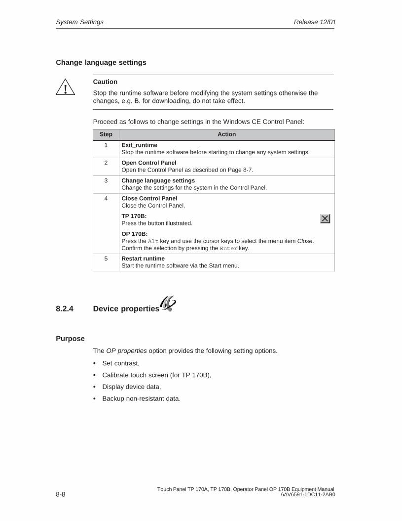
System Settings Release 12/01
8-8Touch Panel TP 170A, TP 170B, Operator Panel OP 170B Equipment Manual
6AV6591-1DC11-2AB0
Change language settings
!Caution
Stop the runtime software before modifying the system settings otherwise thechanges, e.g. B. for downloading, do not take effect.
Proceed as follows to change settings in the Windows CE Control Panel:
Step Action
1 Exit_runtimeStop the runtime software before starting to change any system settings.
2 Open Control PanelOpen the Control Panel as described on Page 8-7.
3 Change language settingsChange the settings for the system in the Control Panel.
4 Close Control Panel Close the Control Panel.
TP 170B:Press the button illustrated.
OP 170B:Press the Alt key and use the cursor keys to select the menu item Close.Confirm the selection by pressing the Enter key.
5 Restart runtimeStart the runtime software via the Start menu.
8.2.4 Device properties
Purpose
The OP properties option provides the following setting options.
� Set contrast,
� Calibrate touch screen (for TP 170B),
� Display device data,
� Backup non-resistant data.

System SettingsRelease 12/01
8-9Touch Panel TP 170A, TP 170B, Operator Panel OP 170B Equipment Manual6AV6591-1DC11-2AB0
Set contrast
Figure 8-3 OP Properties option, Display tab control
Step Action
1 Open the Display tab control (Figure 8-3) in the OP Properties option.
2 Use the Contrast up and Contrast down buttons to adjust the screen contrast.
3 Close the Properties menu on the TP 170B by means of the OK button and onthe OP 170B with the Enter button.
In the case of units with STN displays, the screen contrast can be changed usingthe following key combinations:
Increases the contrast
Reduces the contrast
Note
Wait at least 10 seconds after changing the settings before switching the unit off.Otherwise, the changes will not be saved.

System Settings Release 12/01
8-10Touch Panel TP 170A, TP 170B, Operator Panel OP 170B Equipment Manual
6AV6591-1DC11-2AB0
Calibrate touch screen (TP 170B only)
Recalibrate the Windows CEunit screen if your input is notcorrectly executed.
Press the Recalibrate button tostart the recalibration function.
Figure 8-4 OP Properties option, Touch tab control
Purpose
Depending on the installation position and viewing angle, it is possible that a moreor less strong parallax may occur when operating the TP 170B. In order to preventoperating errors occurring as a result, the screen can be calibrated during thestart-up phase and normal operation.
Step Action
1 Open the Touch tab control (Figure 8-4, Page 8-10) in the OP Properties option.
2 Press the Recalibrate button to start the calibration process.
Five calibration crosses appear in succession on the screen. Follow theinstructions on the screen and touch each respective calibration cross as itappears with a touch pen.
3 Apply calibration:Touch any point of the screen after the calibration process for the new calibrationdata to take effect.
Reject calibration:Wait 30 seconds, until the seconds counter displayed has reached zero, beforerejecting the new calibration data.
If calibration is not performed correctly, the new values are not accepted.
4 Touch the OK button to close the Properties menu.
Configured function
When the Touch Calibration function has been linked to an operating element inthe configuration, the touch screen can be calibrated while in normal operation.The triggering operating element can be configured so that a password must beentered to enable the touch calibration process.
The calibration process is identical with steps described for the start-up phase 2and 3.

System SettingsRelease 12/01
8-11Touch Panel TP 170A, TP 170B, Operator Panel OP 170B Equipment Manual6AV6591-1DC11-2AB0
Persistent storage of registrations
Figure 8-5 OP Properties option, Persistent Storage tab control
Step Action
1 Open the Persistent Storage tab control (Figure 8-5, Page 8-11) in the OPProperties option.
2 Press the OK button to start the storage process.
The current registration settings are stored in the Flash memory.
3 Press the Save Files button to start the copy the files in the RAM file system tothe Flash memory.
When the system is restarted, the files saved are restored in the file system.
4 When using the TP 170B touch panel, close the Settings menu using the OKbutton, and when using the OP 170B move the focus to the tab control headingand press the Enter key.
Display device data
Figure 8-6 Option OP, Device tab control (Example)
Step Action
1 Open the Device tab control (Figure 8-6) in the OP Properties option.
2 Various device data is displayed.
3 Close the menu on the TP 170B by means of the OK button and on the OP 170Bwith the Enter button.

System Settings Release 12/01
8-12Touch Panel TP 170A, TP 170B, Operator Panel OP 170B Equipment Manual
6AV6591-1DC11-2AB0
8.2.5 Screensaver
Figure 8-7 Screensaver option
It is possible to define a period of time (in minutes) for automatic activation of thescreen saver on the operating unit. The screen saver settings are defined in theScreensaver option of the Windows CE Control Panels (refer to Page 8-7).
The screen saver is automatically activated if the operating unit is not operatedwithin the defined period of time.
On entering the value 0, the screen saver is deactivated permanently. The screensaver is deactivated on pressing any key or touching the touch screen. Thefunction assigned to that key is not triggered.
8.2.6 Screen keyboard
This is used to define the position of the screen keyboard when it appears on theoperating unit. Proceed as follows:
Step Action
1 Select the Input Panel option.
2 Move the screen keyboard to the required position.
3 Store the new settings by pressing the Save button.
4 Close the option by pressing the Close Input Panel button or the Enter key.
Note
The screen keyboard is only used for input using the Windows CE Control Panel.

System SettingsRelease 12/01
8-13Touch Panel TP 170A, TP 170B, Operator Panel OP 170B Equipment Manual6AV6591-1DC11-2AB0
8.2.7 Regional settings
Language-specific settings can be defined here, e.g.:
� Date and time format (refer to Page 6-12)
� Decimal separator and list separator (refer to Page 7-24)
The operating unit is supplied with the German language options set.
Note
If the operating system does not support the language set on the operating unit,the language predefined for the operating system is used.
8.2.8 Set printer
A printer can be selected and set up using the Printer option. Some settings areonly relevant for printing a hardcopy of the screen contents and have no influenceon the message logging, e.g. color or quality of graphics printing.
Information on connecting printers is provided on Page 9-19.
Set printer
A printer can be selected and set up at this point. Some settings are only relevantfor printing a hardcopy of the screen contents and have no influence on themessage logging.
The setting possibilities available are dependent on the printer selected. Thefollowing can be selected, for example:
� PrinterSelect the printer from the list to which the operating unit is connected.
� PortSelect the port and baud rate used by the operating unit to transfer data to theprinter, e.g. IF2: 9600.
� Paper sizeSelect the paper size used in the printer, e.g. A4 or Letter.
� Draft modeDefine the quality of the printout of graphics. If the option is activated, printout isperformed in draft quality, if deactivated printout is in high quality.
� OrientationDefine whether the page should be printed in Portrait or Landscape format.
System Settings Release 12/01
8-14Touch Panel TP 170A, TP 170B, Operator Panel OP 170B Equipment Manual
6AV6591-1DC11-2AB0
Note
If a serial printer is connected, the following settings are necessary on the printer:
� RS 232, whereby only the RxD, TxD and GND signals are required (referto Appendix B),
� 8 data bits,
� 1 stop bit,
� No parity,
� Baud rate between 9600 and 57600, printer-dependent.
Default settings
When the operating unit is supplied, the following default settings are defined:
� Printer: EPSON 9 matrix printer
� Port: IF2
� Baud rate: 9600 bit/s

9-1Touch Panel TP 170A, TP 170B, Operator Panel OP 170B Equipment Manual6AV6591-1DC11-2AB0
Installation
In this chapter
This chapter provides information on:
� installation of the operating units (from Page 9-2)
� electrical connections to
– the power supply (Page 9-6)
– the configuration computer (Page 9-15)
– the PLC (Page 9-16)
– printers for TP 170B and OP 170B (Page 9-19)
9

Installation Release 12/01
9-2Touch Panel TP 170A, TP 170B, Operator Panel OP 170B Equipment Manual
6AV6591-1DC11-2AB0
9.1 Mechanical Installation
Installation location and conditions
The operating unit is designed for installation in the front panels of cabinets andconsoles. Cut a mounting cut-out in the front panel in preparation for installation ofthe unit. The thickness of the front panel must not exceed 6 mm. No other holesneed to be drilled for mounting.
Details regarding the installation depth and mounting cut-out are provided on:
� TP 170A: Page 10-2
� TP 170B: Page 10-3
� OP 170B: Page 10-5
Degree of protection
The operating unit must be installed in such a way that at least Protection ClassIP54 is guaranteed. The IP65 degree of protection for the front panel can only beensured when the seal on the front plate of the operating unit is fitted correctly.The degree of protection NEMA 4 can be achieved by implementing the optionalprotective cover. The protective cover also provides protection for the touchpanels.
Notice
The IP65 degree of protection is only guaranteed when the thickness of theoperating panel’s installation support is at least 1.5 mm.
In order to use the protective cover, the metal plate of the installation support musthave a maximum thickness of 3 mm.
!Caution
� The unit must be brought to room temperature before it is commissioned. Ifcondensation forms, do not switch the unit on until it is absolutely dry.
� To prevent the operating unit from overheating during operation,
– the angle of inclination from vertical installation may not exceed a maximumof �35�,
– do not expose the operating unit to direct sunlight,
– ensure that the ventilation slits in the housing remain free after installation.
� The minimum clearance must be maintained at the sides of the operating unitsfor cable feed and air circulation.

InstallationRelease 12/01
9-3Touch Panel TP 170A, TP 170B, Operator Panel OP 170B Equipment Manual6AV6591-1DC11-2AB0
Notice
The operating unit was function-tested before shipping. If a fault occursnevertheless, please enclose a full account of the fault when returning the unit.
9.1.1 Installing the TP 170A or TP 170B
Installation in front panels
Step Action
1 Working from the front, insert the operating unit in the mounting cut-out provided.
Make sure the unit cannot drop out of the front panel before it has been secured.
2 Insert the hooks of the screw-type clamps enclosed in the correspondingrecesses in the housing of the operating unit.
The individual positions are indicated in the figure by means of arrows.
2
Front panel
Operating unit
3 Use a screwdriver to tighten the operating unit from the rear in the front panel.
Note
� Make sure the seal is seated correctly against the front panel.
� Do not overtighten the screws to avoid damage.

Installation Release 12/01
9-4Touch Panel TP 170A, TP 170B, Operator Panel OP 170B Equipment Manual
6AV6591-1DC11-2AB0
9.1.2 Installing the OP 170B
Before installation
If the labeling of the function keys needs to modified, the labeling strips can bereplaced before installing the operating unit or when the unit is already installed.Information on this is provided on Page 10-6.
Installation in front panels
Step Action
1 Working from the front, insert the operating unit in the mounting cut-out provided.
Make sure the unit cannot drop out of the front panel before it has been secured.
2 Insert the hooks of the screw-type clamps enclosed in the correspondingrecesses in the housing of the operating unit.
The individual positions are indicated in the figure by means of arrows.
2
3 Use a screwdriver to tighten the operating unit from the rear in the front panel.
Note
� Make sure the seal is seated correctly against the front panel.
� Do not overtighten the screws to avoid damage.

InstallationRelease 12/01
9-5Touch Panel TP 170A, TP 170B, Operator Panel OP 170B Equipment Manual6AV6591-1DC11-2AB0
9.2 Electrical Installation
Electrical connections
The operating unit requires electrical connections
� to the power supply,
� to the configuration computer (PU or PC),
� to the PLC,
� to the printer (TP 170B and OP 170B).
An electrical connection to the PU/PC is only required for downloading the projectdata. Following the configuration and test phases, a serial printer can beconnected to the operating unit instead of the configuration computer.
EMC compatible installation
A precondition for error-free operation is an EMC hardware design of the PLC andthe use of interference-proof cables. The guidelines on interference-free design ofthe PLCs apply equally to installation of the operating unit.
!Caution
� Only shielded cables are permitted for all signal connections.
� Screw or lock all plug connections.
� Do not install signal lines in the same cable ducts as power cables.
� Siemens AG refuses to accept liability for malfunctions and damage arisingfrom use of self-made cables or cables from other manufacturers.
Grounding conductor connection
Connect the grounding conductor of the operating unit to the rack ground.Use the grounding screw provided and a conducting cable with a diameterof �2.5 mm2.
Reverse battery protection
Note
The operating unit is equipped with reverse poling protection.

Installation Release 12/01
9-6Touch Panel TP 170A, TP 170B, Operator Panel OP 170B Equipment Manual
6AV6591-1DC11-2AB0
Proceed as follows when commissioning the operating unit:
1. Connect the operating unit to the power supply.
2. Switch on the power supply.If the operating unit does not start up, the connections are probably reversed.Swap the connections over in this case.
3. When the operating unit has been powered up, connect the configurationcomputer or other periphery equipment to it.
Power supply
The power supply for the operating unit is connected at the 2-pin plug connector onthe underside of the unit. Use the 2-pin terminal block supplied for this purpose.The terminal block is designed for cables with a cross-section not larger than2.5 mm2.
The figure illustrates a view of the underside of the unit.
GND
+ 24 V DC
1 2
Please refer to the technical data in Appendix A for information on the powersupply requirements.
!Caution
� When using a 24 V supply, make sure that the extra-low voltage is isolatedsafely. Use only power supply units complying with IEC 364-4-41 orHD 384.04.41 (VDE 0100, Part 410).
� The supply voltage must be within the specified voltage range. Voltagesoutside this range can cause malfunctions.
!Warning
Personal injury and equipment damage can occur. If the 24 VDC power supply forthe TP 170A and TP 170B is not correctly applied, components in the automationsystem could be damaged and persons could be injured.
Only use safety extra-low voltage (SELV) for the 24 VDC supply voltage to theTP 170A and TP 170B.
Please refer to the technical data in Appendix A for information on the powersupply requirements.

InstallationRelease 12/01
9-7Touch Panel TP 170A, TP 170B, Operator Panel OP 170B Equipment Manual6AV6591-1DC11-2AB0
9.2.1 TP 170A
Connection elements
Figure 9-3 illustrates the arrangement of the connection elements on the interfaceplate on the underside of the TP 170A unit:
Figure 9-1 Arrangement of connection elements
No. Name Description/Use
Interfaces 1): Level: Usage:� IF1 A RS232 PC, PU
� IF1 B RS422/RS485 (floating) PLC, PC, PU
Grounding connection For connection to cabinet ground
Power supply 2) Connection for power supply (+24 V DC)
Switch 3) To configure interface IF1B
1) Connection pin assignment, see Appendix B.2) Connection pin assignment, see Page 9-6.3) Switch settings, see Page 9-18.

Installation Release 12/01
9-8Touch Panel TP 170A, TP 170B, Operator Panel OP 170B Equipment Manual
6AV6591-1DC11-2AB0
Communication options
Device Connection Interface
Configuration computer (PC, PU) � RS 232 IF1 AConfiguration computer (PC, PU)
� MPI IF1 B
Configuration computer (PC, PU)
� PROFIBUS-DP IF1 B
SIMATIC S7 � MPI
� PROFIBUS-DP
IF1 B
IF1 B
LG (Lucky Goldstar) � RS 232
� RS 422/RS 485
IF1 A
IF1 B
SIMATIC S5 � AS511 (with adapter) IF1 A
SIMATIC 505 � RS 232
� RS 422/RS 485
IF1 A
IF1 B
Modicon (Modbus) � RS 232 IF1 A
Other PLCs � RS 232
� RS 422/RS 485
IF1 A
IF1 B

InstallationRelease 12/01
9-9Touch Panel TP 170A, TP 170B, Operator Panel OP 170B Equipment Manual6AV6591-1DC11-2AB0
9.2.2 TP 170B
Connection elements
Figure 9-3 illustrates the arrangement of the connection elements on the interfaceplate on the underside of the TP 170B:
7
Figure 9-2 Arrangement of connection elements
No. Name Description/Use
Interfaces 1): Level: Usage:� IF2 RS 232 PC, PU, printer
� IF1 A RS 232 PLC
� IF1 B RS 485 (potential free)/RS 422
PLC, PC, PU
Grounding connection For connection to cabinet ground
Power supply 2) Connection for power supply (+24 V DC)
Switch 3) To configure interface IF1B

Installation Release 12/01
9-10Touch Panel TP 170A, TP 170B, Operator Panel OP 170B Equipment Manual
6AV6591-1DC11-2AB0
Description/UseNameNo.
Slot Memory card (CF card)
1) Connection pin assignment, see Appendix B.2) Connection pin assignment, see Page 9-6.3) Switch settings, see Page 9-18.
Communication options
Device Connection Interface
SIMATIC S5 � AS511 (with adapter)
� PROFIBUS-DP
IF1 A
IF1 B
SIMATIC S7 � MPI
� PROFIBUS-DP
IF1 B
IF1 B
SIMATIC 505 � RS 232
� RS 422/RS 485
IF1 A
IF1 B
LG (Lucky Goldstar) � RS 232
� RS 422/RS 485
IF1 A
IF1 B
Modicon (Modbus) � RS 232 IF1 A
Other PLCs � RS 232
� RS 422/RS 485
IF1 A
IF1 B
Configuration computer � RS 232
� RS 485
IF2
IF1 B
Printer
� Local printer � RS 232 IF2

InstallationRelease 12/01
9-11Touch Panel TP 170A, TP 170B, Operator Panel OP 170B Equipment Manual6AV6591-1DC11-2AB0
9.2.3 OP 170B
Connection elements
Figure 9-3 illustrates the arrangement of the connection elements on the interfaceplate on the underside of the OP 170B unit:
7
Figure 9-3 Arrangement of connection elements
No. Name Description/Use
Interfaces 1): Level: Usage:� IF2 RS 232 PC, PU, printer
� IF1 A RS 232 PLC
� IF1 B RS 485 (potential free)/RS 422
PLC, PC, PU
Grounding connection For connection to cabinet ground
Power supply 2) Connection for power supply (+24 V DC)
Switch 3) To configure interface IF1B

Installation Release 12/01
9-12Touch Panel TP 170A, TP 170B, Operator Panel OP 170B Equipment Manual
6AV6591-1DC11-2AB0
Description/UseNameNo.
Slot Memory card (CF card)
1) Connection pin assignment, see Appendix B.2) Connection pin assignment, see Page 9-6.3) Switch settings, see Page 9-18.
9.2.4 Communication options
Device Connection Interface
SIMATIC S5 � AS511 (with adapter)
� PROFIBUS-DP
IF1 A
IF1 B
SIMATIC S7 � MPI
� PROFIBUS-DP
IF1 B
IF1 B
SIMATIC 505 � RS 232
� RS 422/RS 485
IF1 A
IF1 B
Lucky Goldstar � RS 232
� RS 422/RS 485
IF1 A
IF1 B
Modicon (Modbus) � RS 232 IF1 A
Other PLCs � RS 232
� RS 422/RS 485
IF1 A
IF1 B
Configuration computer � RS 232
� RS 485
IF2
IF1 B
Printer
� Local printer � RS 232 IF2

InstallationRelease 12/01
9-13Touch Panel TP 170A, TP 170B, Operator Panel OP 170B Equipment Manual6AV6591-1DC11-2AB0
9.3 Equipotential
Potential differences
Differences of potential can occur in separate system sections which lead to highequipotential flows, e.g. when cable screening is applied on both sides andgrounded at two different system parts.
The cause of potential differences may be due to different mains power feedsources.
!Warning
Cable screening is not designed for potential equalization. Only use lines providedfor the purpose (e.g. with a 16 mm2 cross-section). When setting up MPI/DPnetworks, ensure cables with a sufficient cross-section are used otherwise theinterface hardware may be damaged or even destroyed.
Potential equalization lines
The potential differences must be reduced by the provision of potential equalizationlines so that proper functioning of the electrical components installed isguaranteed.
When installing potential equalization lines, observe the following points:
� The efficiency of the potential equalization is greater the smaller the impedanceof the potential equalization line is.
� If two system parts are connected by screened signal lines, whose screening isconnected on both sides to the grounding/earthed conductor, the impedance ofthe additionally laid potential equalization lines may be maximally 10% of thescreening impedance.
� The cross-section of a potential equalization line must be dimensioned for themaximum equalizing current which can flow. Experience has shown thatpotential equalization lines with a cross-section of 16 mm2 suffice.
� Use potential equalization lines made of copper or galvanized steel. Connectthe lines with the ground connection/ground conductor and protect fromcorrosion.
� Lay the potential equalization lines so that the area between the potentialequalization line and signal lines is small (refer to the following diagram).
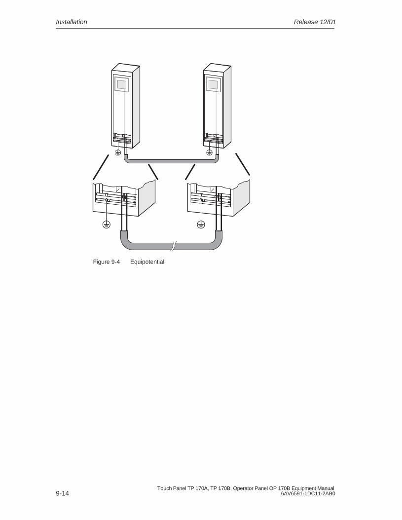
Installation Release 12/01
9-14Touch Panel TP 170A, TP 170B, Operator Panel OP 170B Equipment Manual
6AV6591-1DC11-2AB0
Figure 9-4 Equipotential

InstallationRelease 12/01
9-15Touch Panel TP 170A, TP 170B, Operator Panel OP 170B Equipment Manual6AV6591-1DC11-2AB0
9.4 Connect Configuration Computer
Connection configuration
Figure 9-5 illustrates how to connect a configuration computer (PU or PC) to theoperating unit for downloading project data. Standard cables are available for theconnections shown (refer to the ST80 catalog).
COMIF1A/IF2 1)
PC/PU 7xx
TP 170A/BOP 170B
RS 232 2)
IF1 BMPI/PROFIBUS-DP
RS 485
PC/PU 7xx
1) TP 170A: IF1A,TP 170B, OP 170B: IF2
2) Operating system update only via RS 232 (refer to Chapter 13)
Figure 9-5 Connection configuration diagram for configuration computer

Installation Release 12/01
9-16Touch Panel TP 170A, TP 170B, Operator Panel OP 170B Equipment Manual
6AV6591-1DC11-2AB0
9.5 Connect PLC
Connection configuration diagram for TP 170A
Figure 9-6 illustrates the basic connection possibilities between the TP 170A andPLC. Standard cables are available for the connections shown (refer to the ST80catalog).
PLCs of othermanufacturers
RS 422/RS 485
SIMATIC S71)
1) Use only the approved cables for connection to the SIMATIC S7.2) Any PROFIBUS-DP bus terminal
IF1 B
RS 485
RS 485
TP 170A
PROFIBUS-DP
2)
RS 232IF1 A
PLCs of othermanufacturers
Figure 9-6 Connection configuration for PLCs

InstallationRelease 12/01
9-17Touch Panel TP 170A, TP 170B, Operator Panel OP 170B Equipment Manual6AV6591-1DC11-2AB0
Connection configuration diagram for TP 170B and OP 170B
PU interfaces
RS232(9/25-pin)
RS 422(9-pin)
SIMATIC S5
RS 232
PLCs of othermanufacturers
RS 422
RS 422/RS 485
CPU
SIMATIC 505
SIMATIC S71)
RS 232
1) Use only the approved cables for connection to the SIMATIC S7.2) To enable operation using the serial interface, connect either the IF1A (RS 232) or IF1B
(RS 422/485), but not both. The 1F1B interface can be configured by means of the switch(Page 9-18).
3) Any PROFIBUS-DP bus terminal
IF1A2)
IF1B2)
RS 485
RS 485
TP 170B/OP 170B
PROFIBUS-DP
3)
RS 232Converter
Figure 9-7 Connection configuration for PLCs

Installation Release 12/01
9-18Touch Panel TP 170A, TP 170B, Operator Panel OP 170B Equipment Manual
6AV6591-1DC11-2AB0
Configure interface IF1B
The IF1B interface can be configured via the switches on the rear side of the unit.In this case, the RTS signal is interchanged for RS 485 and the RS 422 receivedata. By default, the RTS signal is not required by the communication peer.
The table shows the permissible switch settings.
Communication Switch Setting
PLCMPI
Standard cable
TP 170BOP 170B ON
1234
No RTS on connector1)
PLCRS 422/RS 485TP 170B
OP 170BON
1234
PLC
PROFIBUS-DP/MPITP 170BOP 170B ON
1234
RTS on pin 4 (default)
PLC
PROFIBUS-DP/MPITP 170BOP 170B
RTS on pin 9 (as PU)
ON
1234
PLC
PROFIBUS-DP/MPITP 170BOP 170B
No RTS on connector1)
ON
1234
1) State on delivery
Compressing the internal program memory with SIMATIC S5
!Caution
With the SIMATIC S5, compression of the internal program memory on the PLC(PU “Compress” function, integrated FB COMPR) is not permitted when anoperating unit is connected. Compression modifies the absolute addresses of theblocks in the program memory. Since the operating unit only reads the address listduring startup, it does not detect any address modifications and subsequentlyaccesses the wrong memory areas.
If compression is inevitable during running operations, the operating unit must beswitched off before compressing.

InstallationRelease 12/01
9-19Touch Panel TP 170A, TP 170B, Operator Panel OP 170B Equipment Manual6AV6591-1DC11-2AB0
9.6 Connecting a Printer to the TP 170B and OP 170B
Connection configuration
Figure 9-8 illustrates how to connect a serial printer to the TP 170B and OP 170B.The units can be used with the following standard printers:
� compatible with ESC/P, 9-pin ESC/P or ESC/P2 (EPSON) e.g. EPSON FX850, Brother 1250
� compatible with PCL3 (Hewlett Packard) HP LaserJet 5M
IF2
Local printer (serial)
ESC/P, 9-pin ESC/P, ESC/P2, PCL
RS 232
TP 170B/OP 170B
Figure 9-8 Printer connection configuration
Information on printer settings is provided on Page 8-13.
Note
� Only use a cable with braided metal screening grounded at each end forconnecting the operating unit and printer.
� Deactivate in the Configuration menu (refer to Page 3-8) the option SerialTransfer Remote Control if a serial printer is to be connected to the operatingunit via the IF2 interface.
� Some printers may require that the ASCII character set used in theconfiguration is defined on the printer as well.

Installation Release 12/01
9-20Touch Panel TP 170A, TP 170B, Operator Panel OP 170B Equipment Manual
6AV6591-1DC11-2AB0
Note
If a serial printer is connected, the following settings are necessary on the printer:
� RS 232, whereby only the RxD, TxD and GND signals are required(refer to Appendix B),
� 8 data bits,
� 1 stop bit,
� No parity,
� Baud rate between 9600 and 57600, printer-dependent.

10-1Touch Panel TP 170A, TP 170B, Operator Panel OP 170B Equipment Manual6AV6591-1DC11-2AB0
Dimensions
In this chapter
This chapter provides information on:
� Dimensions of the TP 170A (Page 10-2),
� Dimensions of the TP 170B (Page 10-3),
� Dimensions of the OP 170B (Page 10-5).
10

Dimensions Release 12/01
10-2Touch Panel TP 170A, TP 170B, Operator Panel OP 170B Equipment Manual
6AV6591-1DC11-2AB0
10.1 TP 170A
Mounting cut-out
For installation in the front panel, the operating unit requires a mounting cut-out(WxH) of 198 –1 mm x 142 –1 mm. The front panel may not exceed a maximumthickness of 6 mm (max. 3 mm if the protective cover is used).
Unit dimensions
196
42212 6
156
���� ������� ����
��� ����
140
Figure 10-1 TP 170A dimensions
Notice
The following free space must be maintained following installation (front view):
50 mm above the unit, 50 mm below the unit, 15 mm to the right of the unit, 70 mm to the left of the unit.

DimensionsRelease 12/01
10-3Touch Panel TP 170A, TP 170B, Operator Panel OP 170B Equipment Manual6AV6591-1DC11-2AB0
10.2 TP 170B
Mounting cut-out
For installation in the front panel, the operating unit requires a mounting cut-out(WxH) of 198 –1 mm x 142 –1 mm. The front panel may not exceed a maximumthickness of 6 mm (max. 3 mm if the protective cover is used).
Unit dimensions
196
42212 6
156
���� ������� ����
��� ����
140
Figure 10-2 TP 170B dimensions

Dimensions Release 12/01
10-4Touch Panel TP 170A, TP 170B, Operator Panel OP 170B Equipment Manual
6AV6591-1DC11-2AB0
Notice
The following free space must be maintained following installation (front view):
50 mm above the unit, 50 mm below the unit, 15 mm to the right of the unit, 70 mm to the left of the unit.

DimensionsRelease 12/01
10-5Touch Panel TP 170A, TP 170B, Operator Panel OP 170B Equipment Manual6AV6591-1DC11-2AB0
10.3 OP 170B
Mounting cut-out
For installation in the front panel, the OP 170B requires a mounting cut-out (WxH)of 229 –1 mm x 241 –1 mm. The thickness of the front panel must not exceed 6 mm.
Unit dimensions
���� ������� ����
��� ����
240
252
227
239
642
Figure 10-3 OP 170B dimensions
Notice
The following free space must be maintained following installation (front view):
50 mm above the unit, 15 mm below the unit, 15 mm to the right of the unit, 70 mm to the left of the unit.

Dimensions Release 12/01
10-6Touch Panel TP 170A, TP 170B, Operator Panel OP 170B Equipment Manual
6AV6591-1DC11-2AB0
10.3.1 Labeling OP 170B function keys
Labeling
The OP 170B function keys are labeled as follows on supply:
� F1 to F14 and
� K1 to K10.
The function keys are labeled by means of 8 labeling strips which are inserted inthe unit from the rear. These strips can be exchanged in order to label theOP 170B specifically for the system.
Exchange labeling strips
!Warning
When the cabinet is opened, certain parts of the system that may conducthazardous voltage are exposed.

DimensionsRelease 12/01
10-7Touch Panel TP 170A, TP 170B, Operator Panel OP 170B Equipment Manual6AV6591-1DC11-2AB0
Proceed as follows:
Step Action
1 Place the unit down with the front plate at the bottom.
2 Remove the labeling strips already inserted.
3 Insert the newly labeled strips in the slots in the front plate with the inscriptionfacing down. The individual positions are indicated in the figure by means ofarrows.
Note:Before inserting the strips, wait until the inscription is dry. A keyboard foil which isdirty on the inside cannot be cleaned and can only be replaced at themanufacturer’s factory.
3
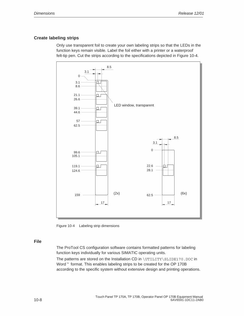
Dimensions Release 12/01
10-8Touch Panel TP 170A, TP 170B, Operator Panel OP 170B Equipment Manual
6AV6591-1DC11-2AB0
Create labeling strips
Only use transparent foil to create your own labeling strips so that the LEDs in thefunction keys remain visible. Label the foil either with a printer or a waterprooffelt-tip pen. Cut the strips according to the specifications depicted in Figure 10-4.
8.5
LED window, transparent
(2x) (6x)
3.10
8.6
21.126.6
39.144.6
3.1
5762.5
99.6105.1
119.1124.6
159
17 17
8.5
3.1
0
22.628.1
62.5
Figure 10-4 Labeling strip dimensions
FileThe ProTool CS configuration software contains formatted patterns for labelingfunction keys individually for various SIMATIC operating units.
The patterns are stored on the Installation CD in \UTILITY\SLIDE170.DOC inWord� format. This enables labeling strips to be created for the OP 170Baccording to the specific system without extensive design and printing operations.

11-1Touch Panel TP 170A, TP 170B, Operator Panel OP 170B Equipment Manual6AV6591-1DC11-2AB0
TP 170B and OP 170B Memory Cards
Purpose
Changeable memory cards can be inserted in the expansion slot at the rear of theoperating units TP 170B (Figure 11-1) and OP 170B (Figure 11-2).
The memory cards can be used, for example, to archive important process data orexecute a backup/restore of the internal Flash memory (refer to Page 3-16).
Figure 11-1 Location of the slot on the TP 170B
Figure 11-2 Location of the slot on the OP 170B
11

TP 170B and OP 170B Memory Cards Release 12/01
11-2Touch Panel TP 170A, TP 170B, Operator Panel OP 170B Equipment Manual
6AV6591-1DC11-2AB0
Cards supported
The operating unit supports the use of cards complying to Compact FlashStandard (CF). The interface supplies the card with 3.3 V.
If the power supply is interrupted inadvertently during normal operation, theoperating unit checks the memory card after power is returned, repairing defectareas if necessary.
Note
The memory card can be inserted and removed with the operating unit switchedon.
Remove memory card
Caution
Before removing a memory card, ensure that the operating unit does not accessthe card during the removal process.
To terminate the runtime software, press the operating element assigned theExit_runtime function in the configuration. Wait until the operating unit Start menu(Figure 3-4, Page 3-8) is displayed.

12-1Touch Panel TP 170A, TP 170B, Operator Panel OP 170B Equipment Manual6AV6591-1DC11-2AB0
Maintenance/Upkeep
Scope
The operating unit has been designed for low maintenance operation. Maintenanceof the unit is limited to
� regular cleaning of the screen,
� regular cleaning of the keyboard overlay (OP 170B).
12.1 Clean Screen/Keyboard
12.1.1 General notes
Preparation
Clean the operating unit screen and keyboard foil of the OP 170B at regularintervals. Use a damp cloth.
!Caution
Do not clean the unit while it is turned on. This ensures that functions are notinadvertently triggered on touching the keys or the touch screen.
Cleaning agents (TP 170A and TP 170B)
Only use water and washing-up liquid or a screen cleaning foam to dampencleaning cloths. Do not spray the cleaning agents directly on the screen but on thecleaning cloth. Never use aggressive solvents or scouring powder.
12
Maintenance/Upkeep Release 12/01
12-2Touch Panel TP 170A, TP 170B, Operator Panel OP 170B Equipment Manual
6AV6591-1DC11-2AB0
12.1.2 Notes on the touch panel units TP 170A and TP 170B
Clean screen
If the Clean Screen function has been assigned to an operating element in theconfiguration, the screen can be cleaned while it is turned on. After the CleanScreen function has been started, all input via the touch screen is deactivated for adefined period of time. The remaining time is indicated by a bar graph.
Protective foil
A protective foil is available for the touch panels TP 170A and TP 170B (refer toCatalog ST80). The protective foil is not part of the material supplied with the units.
The self-adhesive foil prevents the screen being scratched and soiled. In addition,the matt surface of the foil reduces reflections.
The protective foil can be removed as necessary without leaving any adhesiveresidue on the screen.
Caution
Never use sharp or pointed tools to remove the protective foil, such as a knife forinstance. This may cause damage to the touch screen.
Protective cover
A protective cover is available for the TP 170A and TP 170B touch panels. Theprotective cover protects the screen and unit frame from dirt, scratching, chemicalsand reflection. This ensures the operating units can be implemented in hostileenvironments. The cover also guarantees the NEMA4 degree of protection isprovided.
The protective cover is not adhered to the touch panel but clamped between thebase and top frames, so that the operating unit has all-round protection.

13-1Touch Panel TP 170A, TP 170B, Operator Panel OP 170B Equipment Manual6AV6591-1DC11-2AB0
Operating System Update
Purpose
If there is a conflict between the configuration software version and currentoperating system on the operating unit, downloading of a configuration from theconfiguration computer to the operating unit is terminated and a compatibilityconflict is indicated.
In this case, synchronize the operating unit operating system with the version ofthe SIMATIC ProTool CS configuration software.
Note
Updating the operating system causes all the existing data on the operating unit tobe deleted.
Note
An operating system update is only possible using a serial cable.
13

Operating System Update Release 12/01
13-2Touch Panel TP 170A, TP 170B, Operator Panel OP 170B Equipment Manual
6AV6591-1DC11-2AB0
Action
Proceed as follows in order to adapt the operating system on the operating unit tothe configuration software version used:
Step Action
1 Switch off the operating unit’s power supply.
2 Connect interface IF1A or IF2 (serial)1) on the operating unit to the to the serialinterface on the configuration computer using a serial zero modem cable.
3 Start the PTUpdate utility program on the configuration computer. It is containedon the configuration software installation CD. It is located in the \Imagesdirectory, in subdirectory \OP_TP170.
4 Select menu item File → Open and open the image file (file extension .img)appropriate for the operating unit. The image file is located in the same directoryas the PTUpdate utility program. The file name contains the character stringTP170A, TP170B or OP170B.
When the image file has been opened successfully, various information relatedto the version status appears on the screen.
5 Select the menu item File → Settings. Set the interface and applicable baud rate(max. 115200) on the designated interface for the download.
6 Start downloading with the menu option File → Download. When thecorresponding request appears on the screen, switch the operating unit powersupply off.
1) TP 170A: IF1ATP 170B, OP 170B: IF2
When downloading is performed successfully, there is no project data on theoperating unit. The behavior of the operating unit when no project has been loadedis described in Chapter 3.1.

APPENDIX
A Technical Data
B Interface Assignments
C HMI System Messages
D ESD Guidelines

APPENDIX Release 12/01
M-2Touch Panel TP 170A, TP 170B, Operator Panel OP 170B Equipment Manual
6AV6591-1DC11-2AB0

A-1Touch Panel TP 170A, TP 170B, Operator Panel OP 170B Equipment Manual6AV6591-1DC11-2AB0
Technical Data
In this Appendix
This Appendix contains the following technical data for the units TP 170A,TP 170B and OP 170B:
� Housing
� Processor
� Memory
� Software
� Display
� Keyboard (OP 170B)
� Power supply
� Ambient conditions
� Noise immunity and noise transmission
� Approvals
A

Technical Data Release 12/01
A-2Touch Panel TP 170A, TP 170B, Operator Panel OP 170B Equipment Manual
6AV6591-1DC11-2AB0
Housing TP 170A TP 170B OP 170B
External dimensions W x H (mm) 212 x 156 240 x 252
Mounting cut-out W x H (mm) 198–1 x 142–1 229–1 x 241–1
Mounting depth 45 mm
Degree of protection� Front panel IP65/NEMA 12/
NEMA 4 with protective coverIP65/NEMA 4
� Rear panel IP20 IP20
Weight Approx. 0.7 kg Approx. 1 kg
Processor TP 170A TP 170B OP 170B
Type 32 bit RISC
Memory TP 170A TP 170B OP 170B
Configuration memory 320 kByte 768 kByte
Storage media
� Slot for CF card – �
Software TP 170A TP 170B OP 170B
Operating system environment MS Windows CE
Display TP 170A TP 170B OP 170B
Resolution (horizontal x vertical) 320 x 240
Active screen area 116 x 87 116 x 87 116 x 87
Colors 4 Blue Mode 4 Blue Modeor
16 colors
4 Blue Mode
Back-lighting CCFL tube
Half Brightness Life 1) Approx. 50,000 h
1) Time period after which the brightness of the lighting tube only achieves 50 % of itsoriginal value. The specified value is dependent on the operating temperature.

Technical DataRelease 12/01
A-3Touch Panel TP 170A, TP 170B, Operator Panel OP 170B Equipment Manual6AV6591-1DC11-2AB0
Keyboard TP 170A TP 170B OP 170B
Type Touch Membranekeyboard
System keys with dedicatedfunctions
– – 35 (3 withLEDs)
Function keys with configurablefunctions
– – 24 (18 withLEDs)
Those usable as softkeys 14
Power supply TP 170A TP 170B OP 170B
Rated voltage + 24 V DC
Permissible voltage range +18.0...+30.0 V DC
Max. permissible transients 35 V (500 msec)
Time between two transients 50 sec minimum
Power consumption 35 V (500 msec)
35 V (500 msec)
35 V (500 msec)
Typical
� color� mono
–Approx. 0.24 A
Approx. 0.29 AApprox. 0.25 A
–Approx. 0.25 A
Max. constant current Approx. 0.9 A Approx. 0.9 A Approx. 0.9 A
Switch-on current I2t Approx. 0.2A2s
Approx. 0.1A2s
Approx. 0.1A2s
Fuse, internal Electronic
Ambient conditions TP 170A TP 170B OP 170B
Location
Max. permissible angle ofinclination without externalventilation
vertical
�35�
Max. permissible ambienttemperature
� Operation
STN display
– Vertical installation
– Installation angled from theperpendicular to max. 35�
0...+50 �C
0...+35 �C
� Shipping, storage –20...+60 �C
Relative humidityOperation
Shipping, storage
20...90%, no condensation
5...90%, no condensation
Shock loadingOperation
Shipping, storage
15 g/11 msec
25 g/6 msec

Technical Data Release 12/01
A-4Touch Panel TP 170A, TP 170B, Operator Panel OP 170B Equipment Manual
6AV6591-1DC11-2AB0
OP 170BTP 170BTP 170AAmbient conditions
Vibration� Operation 0.035 mm (10 – 58 Hz)
1 g (58 – 500 Hz)
� Shipping, storage 3.5 mm (5 – 8,5 Hz)1 g (8.5 – 500 Hz)
Barometric pressure
� Operation
� Shipping, storage
706 to 1030 hPa
581 to 1030 hPa
Compliance of the named products with the regulations of Directive 89/336 EEC isverified by conformance with the following standards:
Noise immunity TP 170A TP 170B OP 170B
Static discharge (contact discharge/air discharge)
EN 61000-4-2
6 kV/8 kV
RF irradiation EN 61000-4-3
10 V/m, 80% AM,
1 kHz
Pulse modulation EN 61000-4-3
900 MHz �5 MHz
10 V/meff.,50% ED, 200 Hz
RF conduction EN 61000-4-6
150 kHz – 80 MHz
10 V, 80% AM, 1 kHz
Burst interference
� Mains lines
� Supply lines
� Process data lines
� Signal lines
EN 61000-4-4
2 kV
2 kV
2 kV
1 kV
Radio interference TP 170A TP 170B OP 170B
Radio interference level complying toEN 55011
Class A

Technical DataRelease 12/01
A-5Touch Panel TP 170A, TP 170B, Operator Panel OP 170B Equipment Manual6AV6591-1DC11-2AB0
The following approvals have been applied for or already granted on supply.Please refer to the rating plate on the rear of the unit for identification.
Approvals
UL approval UL Recognition Mark 1)
Underwriters Laboratories (UL) complying with Standard UL 508, File E 116536
UL approval In accordance with the UL/CSA Approval Agreement
FM Approval FM Approval
Complying with Factory Mutual Approval Standard Class Number3611 Hazardous (classified) Locations Class I,
Division 2, Group A, B, C, D
Class I, Zone2, Group IIC
FM Approval
Warning:
Personal injury and equipment damage can occur.
Personal injury and equipment damage can occur inhazardous areas if a plug connection is disconnectedfrom the operating unit while the system is running.
In hazardous areas, always switch off the power supplyto the operating unit before disconnecting plugs.
!
FM Approval
Warning:
DO NOT DISCONNECT WHILE CIRCUIT IS LIVEUNLESS LOCATION IS KNOWN TO BENON-HAZARDOUS.
!
1) The UL and CSA file numbers are dependent on the production site. The numbersspecified here changes according to the change of production site.

Technical Data Release 12/01
A-6Touch Panel TP 170A, TP 170B, Operator Panel OP 170B Equipment Manual
6AV6591-1DC11-2AB0

B-1Touch Panel TP 170A, TP 170B, Operator Panel OP 170B Equipment Manual6AV6591-1DC11-2AB0
Interface Assignment
IF1ATable B-1 Assignment of the 9-pin Sub-D plug (pin)
Pin RS 232
1 –
2 RxD
3 TxD
4 –
5 GND
6 –
7 RTS
8 CTS
9 –
IF2Table B-2 Assignment of the 9-pin Sub-D plug (pin)
Pin RS 232
1 DCD
2 RxD
3 TxD
4 DTR
5 GND
6 DSR
7 RTS
8 CTS
9 –
B
5 1
9 6
5 1
9 6

Interface Assignment Release 12/01
B-2Touch Panel TP 170A, TP 170B, Operator Panel OP 170B Equipment Manual
6AV6591-1DC11-2AB0
IF1BTable B-3 Assignment of the 9-pin Sub-D socket
(configuration via switch, see Page 9-18)
Pin PROFIBUS-DPMPI
RS 422 RS 485
1 N. c.
2 N. c.
3 Data B TxD (B) Data B
4 – RxD (B) –
5 GND (floating) frei)
6 +5 V (floating) frei)
7 N. c.
8 Data A TxD (A) Data A
9 – RxD (A) –
5 1
9 6

C-1Touch Panel TP 170A, TP 170B, Operator Panel OP 170B Equipment Manual6AV6591-1DC11-2AB0
HMI System Messages
In this chapter
This chapter contains a selection of important HMI system messages forWindows-based systems. The table indicates when the messages occur and howthey, or their cause, can be cleared. Not every message is relevant for eachoperating unit.
HMI system message parameters
The HMI system messages may contain parameters which are not decoded for theuser but which are relevant in respect of the cause of an error since they provide areference to the source code of the runtime software. These parameters areissued according to the text “Error code:”.
Notice
HMI system messages are issued in the language currently set on the operatingunit.
Number Effect/Cause Remedy
10000 The print job could not be started or wasterminated for an unknown reason.
The printer is incorrectly configured.Or: There are no rights for a network printeravailable.
Check the printer settings and cableconnections.
If a fault occurs repeatedly, contact thehotline.
10001 No printer has been installed or no standardprinter configured.
Install a printer and/or mark one as standardprinter.
10002 The intermediate buffer for printing graphicsis full. Up to two graphics can be buffered.
Do not issue print jobs so quickly insuccession.
10003 Graphics can be buffered again. –
10004 The intermediate buffer for printing lines intext mode (e.g. messages) is full. Up to 1000lines can be buffered.
Do not issue print jobs so quickly insuccession.
10005 Lines of text can be buffered again. –
10006 The Windows print system reports an error.For information on the cause, refer to the textprinted and, if available, the error number.
Printing is not performed or it is incorrect.
Repeat the action, if necessary.
C

HMI System Messages Release 12/01
C-2Touch Panel TP 170A, TP 170B, Operator Panel OP 170B Equipment Manual
6AV6591-1DC11-2AB0
RemedyEffect/CauseNumber
20010 A fault has occurred in the script line calledin from the specified script. Execution of thescript function was, therefore, terminated.
In this case, it is advisable to check anyprevious system messages too.
Select the specified script line in theconfiguration.
Check tags, whether the types used arepermissible.
Check Functions, whether the number andtypes of parameter are correct.
20011 An error has occurred in a script called in bythe script specified. Execution of the scriptfunction- has, therefore, been terminated inthe subscript.
In this case, it is advisable to check anyprevious system messages too.
Select the scripts from the configurationwhich are called in directly or indirectly viathe specified script.
Check tags, whether the types used arepermissible.
Check Functions, whether the number andtypes of parameter are correct.
20012 Inconsistent configuration data is present.Therefore, the script could not be created.
Compile the configuration again.
20013 VBScript.dll is not correctly installed.Therefore, no scripts can be executed.
Re-install ProTool/Pro RT.
20014 A value is returned by the script functionwhich is not written in any configured returntag.
Select the specified script in theconfiguration.
Check whether the script name has beenassigned a value.
20015 Too many scripts have been triggered inquick succession.If more than 20 scripts are queued to beprocessed, any subsequent scripts arerejected.In this case, the script indicated in themessage is not executed.
Check where the scripts are being triggeredfrom.
Extend the times, e.g. the polling time of thetags, which trigger the scripts.
30010 The tag could not accept the function result,e.g. in the case of exceeding the valuerange.
Check the tag type of the functionparameter.
30011 A function could not be executed becausethe function was assigned an invalid value ortype in the parameter.
Check the parameter value and tag type ofthe invalid parameter.
If a tag is used as a parameter, check itsvalue.
40010 The function could not be executed since theparameters could not be converted to acommon tag type.
Check the parameter types in theconfiguration.
40011 The function could not be executed since theparameters could not be converted to acommon tag type.
Check the parameter types in theconfiguration.
50000 The operating unit receives data faster thanit is capable of processing. Therefore, nofurther data is received until the datacurrently available has been processed.Data exchange then resumes.
–
50001 Data exchange has been resumed. –

HMI System MessagesRelease 12/01
C-3Touch Panel TP 170A, TP 170B, Operator Panel OP 170B Equipment Manual6AV6591-1DC11-2AB0
RemedyEffect/CauseNumber
60000 This message is generated by the function“Display system messages”. The text to bedisplayed is transferred to the function as aparameter.
–
60010 The file could not be copied in the directiondefined because one of the two files iscurrently open or the source/target path isnot available.
It is possible that the Windows NT user hasno access rights to one of the two files.
Restart the function or check the paths of thesource/target files.
Using Windows NT with NTFS: The userexecuting ProTool/Pro RT must be grantedaccess rights for the files.
60011 An attempt was made to copy a file to itself.
It is possible that the Windows NT user hasno access rights to one of the two files.
Check the path of the source/target file.
Using Windows NT with NTFS: The userexecuting ProTool/Pro RT must be grantedaccess rights for the files.
70010 The application could not be startedbecause it could not be found in the pathspecified or insufficient memory space wasavailable.
Check whether the application exists in thespecified path or close other applications.
70011 The system time could not be modified. Theerror message only appears in connectionwith area pointer Date/Time PLC. Possiblecauses:
� an impermissible time was transferred inthe PLC job,
� the Windows NT user has no user rightsto modify the system time.
If the first parameter in the system messageis displayed with the value 13, the secondparameter indicates the byte containing theincorrect value.
Check the time which is to be set.
Under Windows NT: The user executingProTool/Pro RT must be assigned the rightsto modify the system time from Windows NT(administration/user manager, guidelines).
70012 An error occurred when executing thefunction Exit Runtime with the option Exitalso Windows.
Windows and ProTool/Pro RT are notterminated.
A possible cause is that other applicationscannot be terminated.
Terminate all applications currently running.
Then terminate Windows.
70013 The system time could not be modifiedbecause an invalid value was entered.Incorrect separators may have been used.
Check the time which is to be set.
70014 The system time could not be modified.Possible causes:
� an impermissible time was transferred
� the Windows NT user has no user rightsto modify the system time,
� Windows rejects the setting request.
Check the time which is to be set.
Under Windows NT: The user executingProTool/Pro RT must be assigned the rightsto modify the system time from Windows NT(administration/user manager, guidelines).
70015 The system time could not be read becauseWindows rejects the reading function.
–

HMI System Messages Release 12/01
C-4Touch Panel TP 170A, TP 170B, Operator Panel OP 170B Equipment Manual
6AV6591-1DC11-2AB0
RemedyEffect/CauseNumber
70016 An attempt was made to select a screen bymeans of a function or job. This is notpossible because the screen numberspecified does not exist.
Or: a screen could not be generated due toinsufficient system memory.
Check the screen number in the function orjob with the screen numbers configured.
Refer the number to a screen, if necessary.
70017 Date/Time is not read from the area pointerbecause the address set in the PLC is eithernot available or has not been set up.
Change the address or set up the address inthe PLC.
70018 Acknowledgement that the password list hasbeen successfully imported.
–
70019 Acknowledgement that the password list hasbeen successfully exported.
–
70020 Acknowledgement for activation of messagerecording.
–
70021 Acknowledgement for deactivation ofmessage recording.
–
70022 Acknowledgement to starting the ImportPassword List action.
–
70023 Acknowledgement to starting the ExportPassword List action.
–
70027 Backing up the RAM file system has beenstarted.
–
70028 Backing up of the RAM file system has beencompleted successfully.
The files from the RAM have been copied inthe Flash memory. Following a restart, thesesaved files will be copied back in the RAMfile system.
–
70029 Backup of the RAM file system has failed.
No backup copy of the RAM file system hasbeen made.
Check the settings in the OP Propertiesdialog and save the RAM file system usingthe Save Files button in the PersistentStorage tab control.
70030 The parameters configured for the functionare faulty.
The connection to the new PLC was notestablished.
Compare the parameters configured for thefunction with the parameters configured forthe PLC and correct them as necessary.
70031 The PLC configured in the function is not anS7 PLC.
The connection to the new PLC was notestablished.
Compare the S7 PLC name parameterconfigured for the function with theparameters configured for the PLC andcorrect them as necessary.
80001 The archive specified is filled to the sizedefined (in percent) and must be storedelsewhere.
Store the file or table by executing a ‘move’or ‘copy’ function.
80002 A line is missing in the specified archive. –

HMI System MessagesRelease 12/01
C-5Touch Panel TP 170A, TP 170B, Operator Panel OP 170B Equipment Manual6AV6591-1DC11-2AB0
RemedyEffect/CauseNumber
80003 The copying process for archiving was notsuccessful.
In this case, it is advisable to check anysubsequent system messages, too.
–
80006 Since archiving is not possible, this causes apermanent loss of the functionality.
In the case of databases, check whether thecorresponding data source exists and startup the system again.
80009 A copying action has been completedsuccessfully.
–
80010 Since the path was incorrectly entered inProTool, this causes a permanent loss of thefunctionality.
Configure the path for the respective archiveagain and restart the system when the fullfunctionality is required.
80012 Archive values are stored in a buffer. If thevalues are read to the buffer faster than theycan be physically written (e.g. using a harddisk), overloading may occur and recordingis then stopped.
Archive less values.
Or increase the recording interval.
80013 The overload status no longer applies.Archiving resumes the recording of allvalues.
–
80014 The same action was triggered twice in quicksuccession. Since the process is already inoperation, the action is only carried out once.
–
80016 The archives are separated by the functionClose archive and the incoming entriesexceed the defined buffer size.
All the jobs in the buffer are deleted.
Reconnect the archives.
80017 The incoming entries cause the definedbuffer size to be exceeded. This can becaused, e.g. by several copying actionsbeing activated at the same time.
All the copy jobs in the buffer are deleted.
Terminate the copy process.
80018 All the archives are reconnected by meansof the DB layer, e.g. after executing thefunction Open_archive.
Values are then written back into the tables.
–
80019 All the archives are separated from the DBlayer and all connections terminated, e.g.after executing the function Close_archive.
Values are temporarily buffered and writtenin the tables when the connection isre-established.
There is no connection to the storagemedium and a change can take place.
–
80020 The max. number of simultaneouslyactivated copy actions has been exceeded.
Copying is not executed.
Wait until the current copying actions havebeen completed and restart the last copyaction.

HMI System Messages Release 12/01
C-6Touch Panel TP 170A, TP 170B, Operator Panel OP 170B Equipment Manual
6AV6591-1DC11-2AB0
RemedyEffect/CauseNumber
80021 An attempt was made to delete an archivewhich is still involved with a copy action.
Deletion has not been executed.
Wait until the current copying action hasbeen completed and restart the last action.
80022 An attempt was made to start a sequencearchive, which is not a sequence archive,from an archive using the functionStart_sequence_archive.
No sequence archive is created.
Check the project for the following:
� the function Start_sequence_archive iscorrectly configured.
� the variable parameters are beingcorrectly provided at the operating unit.
80023 An attempt was made to copy an archive toitself.
The archive is not copied.
Check the project for the following:
� the function Copy_archive is correctlyconfigured.
� the variable parameters are beingcorrectly provided at the operating unit.
80024 The function Copy_archive is configured notto permit copying when the target archivealready contains data (Parameter: Writemode).
The archive is not copied.
Modify the function Copy_archive in theproject, if necessary.
Before initiating the function, delete thetarget archive.
80025 The copy action is interrupted.
Data written up to this point is retained.Deletion of the target table (if configured) isnot executed.
The cancellation is documented by an errorentry $RT_ERR$ at the end of the targettable.
–
80026 The message is issued after all the archiveshave been successfully initialized. Valuesare written in the archives from this momenton. Prior to this, no values are archived eventhough the runtime software is operating.
–
80027 The internal Flash memory has beenspecified as the memory location for anarchive. This is not permissible.
No values will be archived for this archiveand the archive will not be created.
Configure ”Storage Card” as the memorylocation or a network path.
80028 The message serves as a statusacknowledgment that initialization of thearchives is currently running. No values arearchived until system message 80026 isissued.
–
80029 The number of archives specified in themessage could not be initialized. Initializationof the archives has been completed.
The faulty archives are not available forarchiving jobs.
Evaluate the additional system message,related to this message, which is alsoissued.
Check the configuration, the ODBC (OpenDatabase Connectivity) and the specifieddrive.

HMI System MessagesRelease 12/01
C-7Touch Panel TP 170A, TP 170B, Operator Panel OP 170B Equipment Manual6AV6591-1DC11-2AB0
RemedyEffect/CauseNumber
80030 The structure of the table(s) available doesnot match the archiving structure expected.
The archiving process is stopped for thisarchive.
Delete the existing tables manually, inadvance.
80032 Archives can be configured with a functiontrigger. This is triggered as son as thearchive is full. If runtime is started and thearchive is already full, the trigger function willnot be initiated.
The archive specified no longer archivesdata since it is full.
Stop the runtime, delete the archive andrestart the runtime again.
Or:Configure a button in the runtime whichcontains the same actions as the functiontrigger and press it.
110000 The operating mode status has beenchanged. The operating mode is now offline.
–
110001 The operating mode status has beenchanged. The operating mode is now online.
–
110002 The operating mode status has not beenchanged.
Check the connection to the PLCs.
Check whether the address area for the areapointer “Coordination” in the PLC isavailable.
110003 The operating status of the PLC specified ischanged by the function Connect/DisconnectPLC.
The operating mode is now offline.
–
110004 The operating status of the PLC specified ischanged by the function Connect/DisconnectPLC.
The operating mode is now online.
–
110005 An attempt was made to use the functionConnect/Disconnect PLC to switch thespecified PLC to operating mode onlinealthough the entire system is in operatingmode Offline. This switch-over is notpermissible.
The PLC remains in operating mode offline.
Switch the complete system to operatingmode online and execute the function again.
110006 The Colorado system has been extended bythe addition of the User Version area pointer.
If the user version is not correct, the runtimeis stopped.
Check the user versions.
Either the wrong version was entered in thePLC or configuration or the wrongconfiguration was started for the PLC userversion.
120000 The trend is not displayed because anincorrect axis to the trend, or incorrect trend,has been configured.
Change the configuration.
120001 The trend is not displayed because anincorrect axis to the trend, or incorrect trend,has been configured.
Change the configuration.

HMI System Messages Release 12/01
C-8Touch Panel TP 170A, TP 170B, Operator Panel OP 170B Equipment Manual
6AV6591-1DC11-2AB0
RemedyEffect/CauseNumber
120002 The trend is not displayed because the tagassigned tries to access an invalid PLCaddress.
Check whether the data area for the tagexists in the PLC, the configured address iscorrect or the value range for the tag iscorrect.
130000 The action was not executed. Close other applications.
Delete files no longer required from the harddisk.
130001 The action was not executed. Delete files no longer required from the harddisk.
130002 The action was not executed. Close other applications.
Delete files no longer required from the harddisk.
130003 No target data carrier is inserted. Theprocess is stopped.
Check, for example, whether:
� access has been made to the correctdata carrier
� the data carrier has been inserted
130004 The target data carrier is write-protected.The process is stopped.
Check whether access has been made tothe correct data carrier. Remove the writeprotection.
130005 The file is write-protected. The process isstopped.
Check whether access has been made tothe correct file. Modify the file attributes, ifnecessary.
130006 No access to file is possible. The process isstopped.
Check, for example, whether:
� access has been made to the correct file
� the file exists
� a different action prevents simultaneousaccess to the file
140000 Online connection to the PLC has beensuccessfully established.
–
140001 Online connection to the PLC has beendisconnected.
–
140003 No tag updating or writing is executed. Check the connection and whether the PLCis switched on.
Check the parameter definitions in theControl Panel using “Set PU/PC interface”.
Restart the system.
140004 No tag updating or writing is executedbecause the access point or the subrackconfiguration is incorrect.
Check the connection and whether the PLCis switched on.
Check the access point or the subrackconfiguration (MPI, PPI, PROFIBUS) in theControl Panel with “Set PU/PC interface”.
Restart the system.

HMI System MessagesRelease 12/01
C-9Touch Panel TP 170A, TP 170B, Operator Panel OP 170B Equipment Manual6AV6591-1DC11-2AB0
RemedyEffect/CauseNumber
140005 No tag updating or writing is executedbecause the address of the operating unit isincorrect (possibly too high).
Use a different operating unit address.
Check the connection and whether the PLCis switched on.
Check the parameter definitions in theControl Panel using “Set PU/PC interface”.
Restart the system.
140006 No tag updating or writing is executedbecause the baud rate is incorrect.
Select a different baud rate in ProTool/Pro(according to subrack, profile,communication peer, etc.).
140007 No tag updating or writing is executedbecause the bus profile is incorrect(see %1).
The following parameters could not beentered in the registry:
1: Tslot2: Tqui3: Tset4: MinTsdr5: MaxTsdr6: Trdy7: Tid18: Tid29: Gap Factor10: Retry Limit
Check the user defined bus profile.
Check the connection and whether the PLCis switched on.
Check the parameter definitions in theControl Panel using “Set PU/PC interface”.
Restart the system.
140008 No tag updating or writing is executedbecause the configuration data is incorrect:
The following parameters could not beentered in the registry:
0: General errors1: Incorrect version2: Profile cannot be entered in the registry.3: Sub-network type cannot be entered in
the registry.4: Target rotation time cannot be entered
in the registry.5: Highest address (HSA) incorrect.
Check the connection and whether the PLCis switched on.
Check the parameter definitions in theControl Panel using “Set PU/PC interface”.
Restart the system.
140009 No tag updating or writing is executedbecause the module for the S7communication was not found.
Re-install the module in the Control Panelusing “Set PU/PC interface”.
140010 No S7 communication peer could be foundbecause the PLC is switched off.
DP/T:The option “Is not active as the only master”is set in the Control Panel under “Set PU/PCinterface”.
Switch the PLC on.
DP/T:If only one master is connected to thenetwork, deactivate the option “Is not activeas the only master” in “Set PU/PC interface”.
If the network has more than one master,switch this master on. Do not modify anysettings here, otherwise a bus fault mayoccur.
140011 No tag updating or writing is executedbecause communication is interrupted.
Check the connection and that thecommunication peer is switched on.

HMI System Messages Release 12/01
C-10Touch Panel TP 170A, TP 170B, Operator Panel OP 170B Equipment Manual
6AV6591-1DC11-2AB0
RemedyEffect/CauseNumber
140012 There is an initialization problem (e.g. whenProTool/Pro RT has been terminated in theTask Manager).
Or: another application (e.g. STEP7,WINCC) is active with different busparameters and the driver cannot be startedwith the new bus parameters (e.g. baudrate).
Restart the operating unit.
Or start ProTool/Pro RT first and then theother applications.
140013 The MPI cable is not plugged in and, thus,there is no power supply.
Check the connections.
140014 – Modify the operating unit address in theconfiguration in PLC.
140015 Incorrect baud rate
Or: incorrect bus parameter (e.g. HSA)
Or: OP address HSA
Or: incorrect interrupt vector (interrupt doesnot arrive at the driver)
Correct the incorrect parameters.
140016 – Change the interrupt number.
140017 – Change the interrupt number.
140018 The consistency check was deactivated bySimotion Scout.
Only one appropriate note appears.
Activate the consistency check with SimotionScout again and load the configuration in theproject once more.
140019 Simotion Scout loads a new project in thePLC.
Connection to the PLC is interrupted.
Wait until the end of the reconfiguration.
140020 The version in the PLC and that in theconfiguration (FWD file) do not match.
Connection to the PLC is interrupted.
� Load the current version in the PLCusing Simotion Scout.
� Generate the anew project usingProTool CS, end ProTool RT and startwith the new configuration.
150000 No more data is read or written.
Possible causes:
� The cable is defective.
� The PLC does not respond, is defective,etc.
� Connection is established via the wronginterface.
� The system is overloaded.
Check that the cable is plugged in, the PLCis operational, the correct interface is used.
Reboot the system if the system message isdisplayed continuously.
150001 Connection is re-established because thecause of the interruption has beeneliminated.
–

HMI System MessagesRelease 12/01
C-11Touch Panel TP 170A, TP 170B, Operator Panel OP 170B Equipment Manual6AV6591-1DC11-2AB0
RemedyEffect/CauseNumber
160000 No more data is read or written.
Possible causes:
� The cable is defective.
� The PLC does not respond, is defective,etc.
� Connection is established via the wronginterface.
� The system is overloaded.
Check that the cable is plugged in, the PLCis operational, the correct interface is used.
Reboot the system if the system message isdisplayed continuously.
160001 Connection is re-established because thecause of the interruption has beeneliminated.
–
160010 There is no connection to the serverbecause the server identification (CLS-ID)cannot be established.
Values cannot be read or written.
Check the access rights.
160011 There is no connection to the serverbecause the server identification (CLS-ID)cannot be established.
Values cannot be read or written.
Check, for example, whether:
� the server name is correct
� the computer name is correct
� the server is registered
160012 There is no connection to the serverbecause the server identification (CLS-ID)cannot be established.
Values cannot be read or written.
Check, for example, whether:
� the server name is correct
� the computer name is correct
� the server is registered
Information for experienced users:Interpret the value from HRESULT.
160013 The specified server was started as InProcServer. This has not been released and maypossibly lead to incorrect behavior becausethe server is running in the same processarea as the ProTool/Pro RT runtimesoftware.
Configure the server as OutProc Server orLocal Server.
160014 Only one OPC server project can be startedon a PC/MP. An error message appearswhen an attempt is made to start a secondproject.
The second project has no OPC serverfunctionality and cannot be located as anOPC server from external sources.
Do not start a second project with OPCserver functionality on the computer.
170000 1) S7 diagnostics messages are not displayedbecause it is not possible to logon to the S7diagnostics with this unit. The serviceprogram is not supported.
–
170001 1) The S7 diagnostics buffer cannot bedisplayed because communication with thePLC has been switched off.
Switch the PLC online

HMI System Messages Release 12/01
C-12Touch Panel TP 170A, TP 170B, Operator Panel OP 170B Equipment Manual
6AV6591-1DC11-2AB0
RemedyEffect/CauseNumber
170002 1) The S7 diagnostics buffer cannot bedisplayed because reading in thediagnostics buffer (SZL) was terminated dueto an error.
–
170003 1) The display of an S7 diagnostics message isnot possible. An internal error %2 has beenreported.
–
170004 1) The display of an S7 diagnostics message isnot possible. An internal error with errorclass %2, error number %3 has beenreported.
–
170007 1) It is not possible to read in the S7diagnostics buffer (SZL) because it wasterminated with an internal error with errorclass %2 and error code %3.
–
180000 A component/OCX receives configurationdata with a version identification which is notsupported.
Install a newer component.
180001 The system is overloaded because too manyactions have been activated simultaneously.
Not all the actions can be executed, someare rejected.
� Increase the configured cycle times orbasic clock.
� Generate the messages slower (polling).
� Trigger the scripts and functions atgreater intervals.
� If the message appears more frequently: Restart the operating unit.
180002 The screen keyboard could not be activated.
Possible causes:
� The screen keyboard is not generallysupported under Windows 95.
� The file “TouchInputPC.exe” was notregistered due to an incorrectly executedSetup.
If Windows 95 is not available: Install the runtime software again.
190000 It is possible that the tag will not be updated. –
190001 The tag is updated following an error statusafter the cause of the last error state hasbeen eliminated (return to normal operation).
–
190002 The tag is not updated becausecommunication to the PLC has beenswitched off.
Switch on communication via the function“Set Online”.
190004 The tag is not updated because theconfigured address is not available for thistag.
Check the configuration.
190005 The tag is not updated because theconfigured PLC type does not exist for thistag.
Check the configuration.
190006 The tag is not updated because it is notpossible to map the PLC type in the tag type.
Check the configuration.

HMI System MessagesRelease 12/01
C-13Touch Panel TP 170A, TP 170B, Operator Panel OP 170B Equipment Manual6AV6591-1DC11-2AB0
RemedyEffect/CauseNumber
190007 The tag values are not modified because theconnection to the PLC has been terminatedor the tag is offline.
Switch Online or re-establish connection tothe PLC.
190008 The threshold values configured for the taghave been violated, e.g. by
� an entered value,
� a function,
� a script.
Observe the configured or current thresholdvalue of the tag.
190009 An attempt has been made to assign a valueto a tag which is outside the value rangepermitted for this type.
E.g. a value of 260 entered for a byte tag ora value of -3 for a signless word tag.
Observe the value range for the tag type.
190010 The tag is described with values too often(e.g. in a loop triggered by a script).
Values are lost because the maximum of100 event have been stored in the buffer.
Increase the time interval between themulti-writing tasks.
190011 Possible causes:
� The value entered could not be written tothe configured PLC tag because it waseither above or below the value range.The input is rejected and the originalvalue is reset.
Ensure that the value entered is within thevalue range of the PLC tags.
190011
� Connection to the PLC has beeninterrupted.
Check the connection to the PLC.
190012 It is not possible to convert a value from asource format to a target format, e.g.:
� A value should be assigned to a counterwhich is outside the valid,PLC-dependent value range.
� A tag of the type Integer should beassigned a value of the type String.
Check the value range or type of thevariable.
190100 The area pointer is not updated because theconfigured address for this area pointer isnot available.
Type:1 Event messages2 Alarm messages3 PLC acknowledgment4 Operating unit acknowledgment5 LED assignment6 Trend request7 Trend transfer 18 Trend transfer 2
No.:is the consecutive number displayed inProTool/Pro.
Check the configuration.

HMI System Messages Release 12/01
C-14Touch Panel TP 170A, TP 170B, Operator Panel OP 170B Equipment Manual
6AV6591-1DC11-2AB0
RemedyEffect/CauseNumber
190101 The area pointer is not updated because it isnot possible to map the PLC type in the areapointer type.
Parameter type and no.:See message 190100
–
190102 The area pointer is updated following anerror status after the cause of the last errorstate has been eliminated (return to normaloperation).
Parameter type and no.:See message 190100
–
200000 Coordination is not executed because theaddress configured in the PLC does notexist/has not been set up.
Change the address or set up the address inthe PLC.
200001 Coordination is not executed because theaddress configured in the PLC cannot bewritten.
Change the address or set up the address inthe PLC in an area which can be written.
200002 Coordination is not carried out at themoment because the address format of thearea pointer does not match the internalstorage format.
Internal error
200003 Coordination can be executed againbecause the last error status has beeneliminated (return to normal operation).
–
200004 It is possible that coordination is notexecuted.
–
200005 No more data is read or written.
Possible causes:
� The cable is defective.
� The PLC does not respond, is defective,etc.
� The system is overloaded.
Check that the cable is connected and thePLC is in order.
Reboot the system if the system message isdisplayed continuously.
210000 Jobs are not processed because theaddress configured in the PLC does notexist/has not been set up.
Change the address or set up the address inthe PLC.
210001 Jobs are not processed because theaddress configured in the PLC cannot bewritten to/read from.
Change the address or set up the address inthe PLC in an area which can be writtento/read from.
210002 Commands are not executed because theaddress format of the area pointer does notmatch the internal storage format.
Internal error
210003 The job mailbox is processed again becausethe last error status has been eliminated(return to normal operation).
–
210004 It is possible that the job mailbox is notprocessed.
–
210005 A PLC job was triggered by an impermissiblenumber.
Check the PLC program.

HMI System MessagesRelease 12/01
C-15Touch Panel TP 170A, TP 170B, Operator Panel OP 170B Equipment Manual6AV6591-1DC11-2AB0
RemedyEffect/CauseNumber
210006 A fault occurred while attempting to executethe PLC job. The PLC job is, therefore, notexecuted.
Observe the subsequent/previous systemmessage, if appropriate.
Check the parameter types in the PLC job.
Compile the configuration again.
220000 2) See footnote See footnote
220001 The tag is not downloaded because theassociated channel/the unit does not supportdownloading the data type bool/bit.
Change the configuration.
220002 The tag is not downloaded because theassociated channel/the unit does not supportdownloading the data type byte.
Change the configuration.
220003 The associated driver could not beuploaded. It is possible that the driver is notinstalled.
Install the driver by re-installingProTool/Pro RT.
220004 Communication is terminated and no updateis executed because the cable is notconnected or is defect etc.
Check the connection.
220005 Communication is running. –
220006 The connection is established to thespecified PLC at the specified interface.
–
220007 The connection to the specified PLC at thespecified interface is disconnected.
Check that:
� the cable is plugged in
� the PLC is OK
� the correct interface is used
� the configuration is OK (interfaceparameters, protocol settings, PLCaddress).
Reboot the system if the system message isdisplayed continuously.
220008 The PLC driver cannot access the specifiedinterface or open it. It is possible that anotherapplication is using this interface or aninterface is used which is not available onthe target device.
There is no communication with the PLC.
Terminate all the programs which access theinterface and reboot the computer.
Use another interface which is available inthe system.
230000 The value entered could not be accepted.The entered value is rejected and theprevious value is specified again.
Either the value range has been exceededor impermissible characters were entered.
Enter a permissible value.
230002 Since the current password level isinadequate or the password dialog box wasclosed with ESC, the entry is rejected andthe previous value is specified again.
Activate an adequate password level usingLogin.

HMI System Messages Release 12/01
C-16Touch Panel TP 170A, TP 170B, Operator Panel OP 170B Equipment Manual
6AV6591-1DC11-2AB0
RemedyEffect/CauseNumber
230003 Changeover to the specified screen is notexecuted because the screen is notavailable/configured. The current screenremains selected.
Configure the screen.
Check the selection function.
240000 3) Runtime is operating in Demo mode.
There is either no Stopcopy license or it isdefect.
Load the license.
240001 3) Runtime is operating in Demo mode.
Too many tags are configured for theinstalled version.
Load an adequate license / powerpack.
240002 3) Runtime is operating with a time-limitedstandby authorization.
Restore the full authorization.
240003 Authorization cannot be executed.
ProTool/Pro RT is running in Demo mode.
Restart ProTool/Pro RT or reinstall it.
240004 Error during reading the standbyauthorization.ProTool/Pro RT is running in Demo mode.
Restart ProTool/Pro RT, install theauthorization or repair the authorization (seeCommissioning Instructions SoftwareProtection).
250000 The tag in the specified line in Status/Controlis not updated because the addressconfigured for this tag is not available.
Check the set address and then check thatthe address has been set up in the PLC.
250001 The tag in the specified line in Status/Controlis not updated because the PLC typeconfigured for this tag is not available.
Check the set address.
250002 The tag in the specified line in Status/Controlis not updated because it is not possible tomap the PLC type in the tag type.
Check the set address.
250003 No connection could be established to thePLC. The tags will not be updated.
Check the connection to the PLC. Checkthat the PLC is switched on and online isactivated.
260000 A password has been entered which isunknown to the system. Therefore, thelowest password level has been set. Thiscorresponds to the status following Logout.
Enter a known password in the passwordinput field (with corresponding level).
260001 A password has been entered whoseassigned level does not permit execution ofthe function.
The password level currently set is displayedfor information purposes.
Modify the password level in the passwordinput field enter a password with asufficiently high level.
260003 The user has logged off from the system. Ifthe password level is 0, no user is loggedon.
–
270000 A tag is not displayed in the messagebecause it attempts to access an invalidaddress in the PLC.
Check whether the data area for the tagexists in the PLC, the configured address iscorrect or the value range for the tag iscorrect.
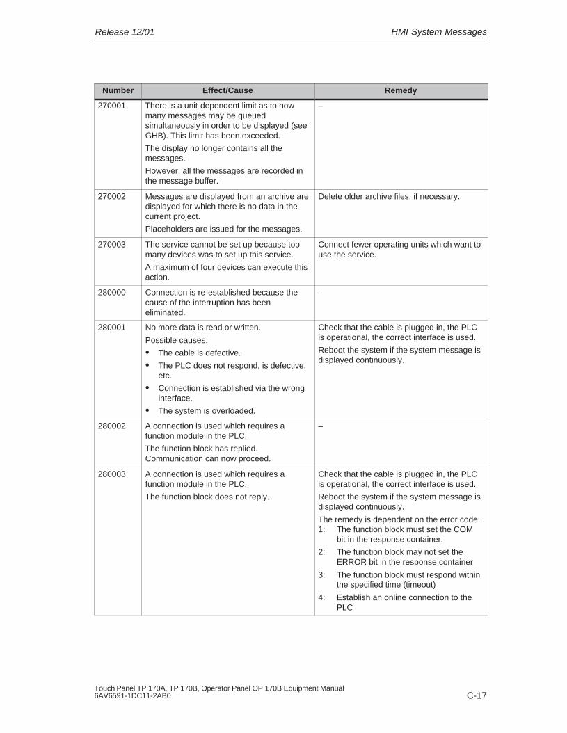
HMI System MessagesRelease 12/01
C-17Touch Panel TP 170A, TP 170B, Operator Panel OP 170B Equipment Manual6AV6591-1DC11-2AB0
RemedyEffect/CauseNumber
270001 There is a unit-dependent limit as to howmany messages may be queuedsimultaneously in order to be displayed (seeGHB). This limit has been exceeded.
The display no longer contains all themessages.
However, all the messages are recorded inthe message buffer.
–
270002 Messages are displayed from an archive aredisplayed for which there is no data in thecurrent project.
Placeholders are issued for the messages.
Delete older archive files, if necessary.
270003 The service cannot be set up because toomany devices was to set up this service.
A maximum of four devices can execute thisaction.
Connect fewer operating units which want touse the service.
280000 Connection is re-established because thecause of the interruption has beeneliminated.
–
280001 No more data is read or written.
Possible causes:
� The cable is defective.
� The PLC does not respond, is defective,etc.
� Connection is established via the wronginterface.
� The system is overloaded.
Check that the cable is plugged in, the PLCis operational, the correct interface is used.
Reboot the system if the system message isdisplayed continuously.
280002 A connection is used which requires afunction module in the PLC.
The function block has replied.Communication can now proceed.
–
280003 A connection is used which requires afunction module in the PLC.
The function block does not reply.
Check that the cable is plugged in, the PLCis operational, the correct interface is used.
Reboot the system if the system message isdisplayed continuously.
The remedy is dependent on the error code:1: The function block must set the COM
bit in the response container.
2: The function block may not set theERROR bit in the response container
3: The function block must respond withinthe specified time (timeout)
4: Establish an online connection to thePLC

HMI System Messages Release 12/01
C-18Touch Panel TP 170A, TP 170B, Operator Panel OP 170B Equipment Manual
6AV6591-1DC11-2AB0
RemedyEffect/CauseNumber
280004 The online connection to the PLC has beeninterrupted. There is no data exchange atpresent.
Check the PLC parameters in ProTool Pro:baud rate, block length, station address.
Check that the cable is plugged in, the PLCis operational, the correct interface is used.
Reboot the system if the system message isdisplayed continuously.
290000 The tag could not be read or written. It isassigned the start value.
The message can be entered in themessage buffer for up to four more failedtags, if necessary. After that, the messagenumber 290003 is issued.
Check in the configuration that the addresshas been set up in the PLC.
290001 An attempt has been made to assign a valueto a tag which is outside the value rangepermitted for this type.
The message can be entered in themessage buffer for up to four more failedtags, if necessary. After that, the messagenumber 290004 is issued.
Observe the value range for the tag type.
290002 It is not possible to convert a value from asource format to a target format.
The message can be entered in themessage buffer for up to four more failedtags, if necessary. After that, the messagenumber 290005 is issued.
Check the value range or type of thevariable.
290003 This message is issued when messagenumber 290000 is triggered more than fivetimes.
In this case, no further individual messagesare generated.
Check in the configuration that the tagaddresses have been set up in the PLC.
290004 This message is issued when messagenumber 290001 is triggered more than fivetimes.
In this case, no further individual messagesare generated.
Observe the value range for the tag type.
290005 This message is issued when messagenumber 290002 is triggered more than fivetimes.
In this case, no further individual messagesare generated.
Check the value range or type of thevariable.
290006 The threshold values configured for the taghave been violated by values entered.
Observe the configured or current thresholdvalue of the tag.
290007 There is a difference between the sourceand target structure of the recipe currentlybeing processed. The target structurecontains an additional data record tag whichis not available in the source structure.
The data record tag specified is assigned itsstart value.
Insert the specified data record tag in thesource structure.

HMI System MessagesRelease 12/01
C-19Touch Panel TP 170A, TP 170B, Operator Panel OP 170B Equipment Manual6AV6591-1DC11-2AB0
RemedyEffect/CauseNumber
290008 There is a difference between the sourceand target structure of the recipe currentlybeing processed. The source structurecontains an additional data record tag whichis not available in the target structure andtherefore cannot be assigned.
The value is rejected.
Remove the specified data record tag in thespecified recipe from the project.
290010 The storage location configured for therecipe is not permitted.
Possible causes: Impermissible characters, write protected,data medium full or does not exist.
Check the path specification configured.
290011 The data record specified by the numberdoes not exist.
Check the source for the number (constantor variable value).
290012 The recipe specified by the number does notexist.
Check the source for the number (constantor variable value).
290013 An attempt was made to save a data recordunder a data record number which alreadyexists.
The process is not executed.
� Check the source for the number(constant or variable value).
� Delete the data record beforehand.
� Change the function parameter “Overwrite”.
290014 The file specified to be imported could not befound.
� Check the file name.
� Ensure that the file is in the specifieddirectory.
290020 Acknowledgement that downloading of datarecords from operating unit to PLC hasstarted.
–
290021 Acknowledgement that downloading of datarecords from operating unit to PLC has beencompleted without any errors.
–
290022 Acknowledgement that downloading of datarecords from operating unit to PLC has beenterminated due to an error.
Check the configuration:
� have the tag addresses been set up inthe PLC?
� does the recipe number exist?
� does the data record number exist?
� has the function parameters ”Overwrite”?
290023 Acknowledgement that downloading of datarecords from the PLC to the operating unithas started.
–
290024 Acknowledgement that downloading datarecords from the PLC to the operating unithas been completed without any errors.
–

HMI System Messages Release 12/01
C-20Touch Panel TP 170A, TP 170B, Operator Panel OP 170B Equipment Manual
6AV6591-1DC11-2AB0
RemedyEffect/CauseNumber
290025 Acknowledgement that downloading of datarecords from the PLC to the operating unithas been terminated due to an error.
Check the configuration:
� have the tag addresses been set up inthe PLC?
� does the recipe number exist?
� does the data record number exist?
� has the function parameters ”Overwrite”?
290026 An attempt has been made to read/write adata record although the data mailbox is notfree at present.
This error may occur in the case of recipesfor which downloading with synchronizationhas been configured.
Set the data mailbox status to zero.
290027 No connection to the PLC can beestablished at present. Therefore, the datarecord can neither be read nor written.
Possible causes: No physical connection to the PLC (no cableplugged in, cable is defect) or the PLC isswitched off.
Check the connection to the PLC.
290030 This message is issued after reselecting ascreen that contains a recipe display inwhich a data record has already beenselected.
Reload the data record from the datamedium or retain the current values.
290031 While saving, it was detected that a datarecord with the specified number alreadyexists.
Overwrite the data record or cancel theprocess.
290032 While exporting data records, it was detectedthat a file with the specified name alreadyexists.
Overwrite the file cancel the process.
290033 Confirmation request before deleting datarecords.
–
290040 A data record error with error code %1 hasoccurred which cannot be described in moredetail.
The action was canceled.
It might be that the data mailbox has notbeen installed correctly on the PLC.
Check that the data carrier, the data record,the data mailbox and, if necessary, theconnection to the PLC.
Trigger the action again after waiting a shortperiod.
If the error occurs again, please contact theCustomer Support. Specify the error codedisplayed.
290041 A data record or file cannot be savedbecause the data medium is full.
Delete files no longer required.
290042 An attempt was made to execute severalrecipe actions simultaneously.
The last action was not executed.
Trigger the action again after waiting a shortperiod.
290043 Confirmation request before storing datarecords.
–

HMI System MessagesRelease 12/01
C-21Touch Panel TP 170A, TP 170B, Operator Panel OP 170B Equipment Manual6AV6591-1DC11-2AB0
RemedyEffect/CauseNumber
290044 The data store for the recipe has beendestroyed and will be deleted.
–
290050 Acknowledgement that the exportation ofdata records has started.
–
290051 Acknowledgement that the exportation ofdata records has been completedsuccessfully.
–
290052 Acknowledgement that the exportation ofdata records has been terminated due toerrors.
Ensure that the structure of the data recordson the data medium and the current recipestructure on the operating unit are identical.
290053 Acknowledgement that the importation ofdata records has been started.
–
290054 Acknowledgement that the importation ofdata records has been completedsuccessfully.
–
290055 Acknowledgement that the importation ofdata records has been terminated due toerrors.
Ensure that the structure of the data recordson the data medium and the current recipestructure on the operating unit are identical.
290056 The value in the specified line/column couldnot be read/written without errors.
The action was canceled.
Check the specified line/column.
290057 The tags of the recipe specified have beenswitched from operating mode “offline” to“online”.
Each modification of a tag in this recipe isnow immediately transferred to the PLC.
–
290058 The tags of the recipe specified wereswitched from operating mode “online” to“offline”.
Modifications to tags in this recipe are nolonger immediately transferred to the PLCbut must be transferred there explicitly bymeans of downloading a data record, ifnecessary.
–
290059 Acknowledgement that the specified datarecord has been stored successfully.
–
290060 Check-back message that the data recordmemory has been successfully erased.
–
290061 Check-back message, that erasing the datarecord memory was aborted with errors.
–
290068 Request to confirm whether all data recordsin the recipe should be deleted.
–
290069 Request to confirm whether all data recordsof all recipes should be deleted.
–
290070 The data record specified is not contained inthe import file.
Check the source of the data record numberor data record name(constant or tag value).

HMI System Messages Release 12/01
C-22Touch Panel TP 170A, TP 170B, Operator Panel OP 170B Equipment Manual
6AV6591-1DC11-2AB0
RemedyEffect/CauseNumber
300000 Process monitoring (e.g. using PDiag orS7-Graph) has been incorrectlyprogrammed: More messages are queuedthan specified in the technical data of theCPU. No further ALARM_S messages canbe managed by the CPU and reported tooperating systems.
Change the CPU configuration.
310000 An attempt is being made to print too manyprotocols simultaneously.
Since only one protocol can be printed at atime, the print job is rejected.
Wait until printout of the last active protocolhas been concluded.
Repeat the print job, if necessary.
310001 An error occurred on triggering the printer.The protocol is either not printed or printedwith errors.
Evaluate the additional system message,related to this message, which is alsoissued.
Repeat the print job, if necessary.
320000 The movements have already beenindicated by another device.
The movements can no longer be served.
Select the movements on the other displayunits and select the movement screen on therequired display unit.
320001 The network is too complex.
The defective operands cannot bedisplayed.
Display the network in AWL.
320002 No diagnostics-capable alarm messageshave been selected.
The units related to the alarm messagescould not be selected.
Select a diagnostics-capable alarm messagein the message screen ZP_ALARM.
320003 No alarm messages exist in respect of theselected unit.
No network can be displayed in the detaildisplay.
Select the defective unit in the general viewscreen.
320004 The required signal statuses could not beread by the PLC.
The defective operands cannot beestablished.
Check the consistency between theconfiguration on the display unit and the PLCprogram loaded.
320005 The project contains ProAgent partitionswhich are not installed.
No ProAgent diagnostics can be performed.
In order to run the project, install theProAgent option packet.
320014 The selected PLC cannot be evaluated forProAgent.
The message display configured with theEvaluate_message_display_fault functioncould not be found.
Check the parameters of theEvaluate_message_display_fault
function.
1) The optional parameter %1 at the start of the message may contain an identification for the S7 connectionwhen several S7s are in parallel operation and are connected to diagnostics equipment.
2) A WinCC channel provides the message texts via an interface. This text is issued via this message.ProTool/Pro RT has no influence on this texts.
3) The specified text comes from the component resources.

HMI System MessagesRelease 12/01
C-23Touch Panel TP 170A, TP 170B, Operator Panel OP 170B Equipment Manual6AV6591-1DC11-2AB0
Procedure in the case of “internal errors”
Please proceed as follows in the case of all system messages related to “internalerrors”:
1. Start up the operating unit again.
2. Download the configuration again.
3. Switch the operating unit off, stop the PLC and then restart both.
4. If the error occurs again, please contact the SIMATIC Customer Support. Makereference to the specified error number and message tags.

HMI System Messages Release 12/01
C-24Touch Panel TP 170A, TP 170B, Operator Panel OP 170B Equipment Manual
6AV6591-1DC11-2AB0

D-1Touch Panel TP 170A, TP 170B, Operator Panel OP 170B Equipment Manual6AV6591-1DC11-2AB0
ESD Guidelines
What does ESD mean?
Virtually all present-day modules incorporate highly integrated MOS devices orcomponents. For technological reasons, these electronic components are verysensitive to overvoltages and consequently therefore to electrostatic discharge:
These devices are referred to in German as Elektrostatisch GefährdetenBauelemente/ Baugruppen: “EGB”
The more frequent international name is:
“ESD” (Electrostatic Sensitive Device)
The following symbol on plates on cabinets, mounting racks or packages drawsattention to the use of electrostatic sensitive devices and thus to the contactsensitivity of the assemblies concerned:
ESDs may be destroyed by voltages and energies well below the perceptionthreshold of persons. Voltages of this kind occur as soon as a device or anassembly is touched by a person who is not electrostatically discharged . Devicesexposed to such overvoltages cannot immediately be detected as defective in themajority of cases since faulty behavior may occur only after a long period ofoperation.
Precautions against electrostatic discharge
Most plastics are capable of carrying high charges and it is therefore imperativethat they be kept away from sensitive components.
When handling electrostatic sensitive devices, make sure that persons, workplacesand packages are properly grounded.
D

ESD Guidelines Release 12/01
D-2Touch Panel TP 170A, TP 170B, Operator Panel OP 170B Equipment Manual
6AV6591-1DC11-2AB0
Handling ESD assemblies
A general rule is that assemblies should be touched only when this cannot beavoided owing to the work that has to performed on them. Under no circumstancesshould you handle printed-circuit boards by touching device pins or circuitry.
You should touch devices only if
� you are grounded by permanently wearing an ESD wrist strap or
� you are wearing ESD shoes or ESD shoe-grounding protection straps inconjunction with an ESD floor.
Before you touch an electronic assembly, your body must be discharged. Thesimplest way of doing this is to touch a conductive, grounded object immediatelybeforehand – for example, bare metal parts of a cabinet, water pipe etc.
Assemblies should not be brought into contact with charge-susceptible and highlyinsulating materials such as plastic films, insulating table tops and items of clothingetc. containing synthetic fibers.
Assemblies should be deposited only on conductive surfaces (tables with an ESDcoating, conductive ESD cellular material, ESD bags, ESD shipping containers).
Do not place assemblies near visual display units, monitors or television sets(minimum distance to screen > 10 cm).
Measuring and modifying ESD assemblies
Perform measurements on ESD assemblies only when
� the measuring instrument is grounded – for example, by means of a protectiveconductor – or
� the measuring head has been briefly discharged before measurements aremade with a potential-free measuring instrument – for example, by touching abare metal control cabinet.
When soldering, use only grounded soldering irons.
Shipping ESD assemblies
Always store and ship assemblies and devices in conductive packing – forexample, metallized plastic boxes and tin cans.
If packing is not conductive, assemblies must be conductively wrapped before theyare packed. You can use, for example, conductive foam rubber, ESD bags,domestic aluminum foil or paper (never use plastic bags or foils).
With assemblies containing fitted batteries, make sure that the conductive packingdoes not come into contact with or short-circuit battery connectors. If necessary,cover the connectors beforehand with insulating tape or insulating material.

Glossary-1Touch Panel TP 170A, TP 170B, Operator Panel OP 170B Equipment Manual6AV6591-1DC11-2AB0
Glossary
A
Acknowledgement
Acknowledgement of an alarm message on the operating unit confirms that it hasbeen noted. After acknowledgement, the message disappears from the operatingunit. Alarm messages can be acknowledged either on the operating unit or PLC.Alarm messages can be compiled into groups so that several messages can beacknowledged simultaneously.
Acknowledgement groups
During configuration, several alarm messages can be compiled to form anacknowledgement group. After acknowledging the first message, all the othermessages belonging to the same group are simultaneously acknowledged. Thisenables, for example, acknowledgement of alarm messages for the cause of afault and all resulting faults (group acknowledgement).
Alarm message
Provides information on the operating unit concerning operating errors on themachine or system connected to the PLC. The message text may also containcurrent measured values.
Since alarm messages indicate abnormal operating status, they must beacknowledged.
ALARM_S
Active message procedure by which the CPU issued messages to all theregistered network participants. ALARM_S messages are configured in STEP 7.
Archive
A memory area on a data storage medium in which messages or tags can bestored. The size of the archive is defined in ProTool/Pro CS.

Glossary Release 12/01
Glossary-2Touch Panel TP 170A, TP 170B, Operator Panel OP 170B Equipment Manual
6AV6591-1DC11-2AB0
Area pointer
Defines a memory area in the PLC for data exchange between the PLC andoperating unit.
B
Bar graphs
Represent values from the PLC as rectangular areas. This is a way of displayingfilling levels or workpiece numbers, for example, on the operating unit.
Baud rate
Rate of speed at which data is downloaded. Baud rate is specified in Bit/s.
Blank
Switch off or dimming the screen back-lighting.
Boot
A loading process which downloads the operating system in the working memoryof the operating unit
Buttons
A virtual button on the operating unit screen. Buttons on operating units with touchscreens are contact sensitive.

GlossaryRelease 12/01
Glossary-3Touch Panel TP 170A, TP 170B, Operator Panel OP 170B Equipment Manual6AV6591-1DC11-2AB0
C
Clicking
Configurable event which can trigger a function assigned to a button, for example,when the button is pressed and released (clicked) within the contour of the button.
If the button is pressed using the mouse button or finger (when using touch panels)but moved outside the contour before releasing, the operating unit does notinterpret the action as a click event.
Combo box
Contains a list of entries from which one can be selected on the operating unit.
Configuration
Definition of system-specific default settings, messages and screens using theconfiguration software ProTool.
D
Data record
A recipe containing data. A recipe can be comprised of several data records.When a data record is downloaded, all the assigned data is transferred to the PLCtogether and synchronously.
Display message
A screen object with configurable filter criteria which is used to display the volatilemessage buffer or message archive.
Display period
Defines whether and how long a system message is displayed on the operatingunit.
Download
The transfer of run-capable project data to the operating unit. Connect theoperating unit to the configuration computer with a standard cable beforehand.
Download mode
Operating unit operating mode in which data can be downloaded from theconfiguration computer to the operating unit (also refer to Download).

Glossary Release 12/01
Glossary-4Touch Panel TP 170A, TP 170B, Operator Panel OP 170B Equipment Manual
6AV6591-1DC11-2AB0
E
Event
Functions are triggered after defined events are received, e.g. on pressing orreleasing keys or buttons. Events can be configured according to objects.
Event message
Provides information on the operating unit concerning the operating statuses of themachine or system connected to the PLC. The message text may also containcurrent measured values.
F
Fixed window
A configurable window which always appears at the top of the screen whosecontent is independent of the screen currently open. The fixed window can be usedto display important process magnitudes or date and time, for example.
Flash memory
Programmable memory which can be electrically deleted and written to againsegment-by-segment.
Function key
Key on the operating unit to which a configurable function can be assigned. Afunction key with a global function assignment always initiates the same functionregardless of the screen currently open. A function key with a local functionassignment (softkey) can have a different function for each screen.
G
Global tag
This is a process tag linked to the PLC. Global tags have a fixed address in thePLC. The operating unit accesses this address for reading and writing purposes.
Graphic box
A graphic can be selected by selecting an entry in the graphic list.

GlossaryRelease 12/01
Glossary-5Touch Panel TP 170A, TP 170B, Operator Panel OP 170B Equipment Manual6AV6591-1DC11-2AB0
Graphics list
A list in which each value relates to a tag assigned to a graphic. This enables, forexample, the assigned graphic to be displayed on the operating unit output fieldinstead of the value.
Group acknowledgement
During the configuration, each alarm message can be assigned to anacknowledgement group. When the alarm message is acknowledged, all theother alarm messages in the same group are simultaneously acknowledged.
H
Hardcopy
Represents a printout of the current screen content. Windows called in on top arenot printed.
Help text
Configurable, additional information on messages, screens and fields. The helptext concerning an alarm message can, for example, contain information on thecause of the fault and methods of elimination.
I
Icon
Pixel graphic of a fixed size, e.g. assigned to a softkey, to identify its function.
Input field
Enables the user to enter values which are subsequently downloaded to the PLC.
Invisible buttons
Buttons which are only visible during configuration, not on the operating unit. Ifinvisible buttons are superimposed on components in the process screen, therespective components can be operated by clicking the button with the mouse orpressing them on the touch screen.

Glossary Release 12/01
Glossary-6Touch Panel TP 170A, TP 170B, Operator Panel OP 170B Equipment Manual
6AV6591-1DC11-2AB0
L
Limit value
Configurable values of a tag defining a value range. Attempts to define valuesoutside these limits, may cause the following effects on the operating unit:
� Input fieldinput is rejected
� Output fieldvalues are displayed in the configured color
� Trend/Barvalues are displayed in the configured color
Local tag
A tag without a link to the PLC. Local tags are only available on the operating unit.
Logout time
Configurable interval of time after which the password level is reset to zero whenthe operating unit is not used.
M
Message arrival
Time at which a message was triggered by the PLC or operating unit.
Message buffer
Memory area in the operating unit in which message events can be stored inchronological order as they arrive. Event messages and alarm messages arestored in separate message buffers.
Message departure
Time at which a message was withdrawn by the PLC.
Message events
These are stored in chronological order in the operating unit message archive.Message events consist of:
� Message arrival
� Message acknowledgement
� Message departure

GlossaryRelease 12/01
Glossary-7Touch Panel TP 170A, TP 170B, Operator Panel OP 170B Equipment Manual6AV6591-1DC11-2AB0
Message indicator
A configurable graphical symbol displayed on the operating unit when at least onealarm message is present.
Message logging
Printout of messages parallel to their display on the operating unit display.
Message view
Screen object to display the volatile message buffer and/or message archive.
N
Normal operation
Operating unit operating mode in which messages are displayed and screens canbe operated.
O
Object
Is a component part of a screen or message. Depending on the object type,objects serve to display or enter texts and values on the operating unit.
Output field
Displays current values from the PLC on the operating unit.
P
Password
A character string which must be entered on the operating unit before a protectedfunction can be activated. Each password is assigned to a defined passwordlevel.
Password level
The rights to use operating units can be specifically restricted to certain users anduser groups. To do this, the individual functions and operating elements areassigned to hierarchically defined password levels. The password level linked tothe password allocates the rights to execute functions on the operating unitbelonging to that level or lower.

Glossary Release 12/01
Glossary-8Touch Panel TP 170A, TP 170B, Operator Panel OP 170B Equipment Manual
6AV6591-1DC11-2AB0
Password list
A screen object for entering passwords related to different authorization levels.
PLC
General term for units and systems with which the operating unit communicates(e.g. SIMATIC S7).
PLC job
PLC jobs can be used by the PLC to trigger functions on the operating unit, e.g.display a screen.
Power-up test
Checks the status of the CPU and memory each time the power is switched on.
Print screen
Printout of a copy of the screen contents.
Process screen
The display of process values and process progress on the operating unit in theform of screens, which may contain graphics, texts and values.
Programmable controller
PLC from the SIMATIC S5 series (e.g. AG S5-115U/135U).
Programmable system
PLC from the SIMATIC S7 series (SIMATIC S7-200/300/400).
ProSave
A service tool which provides all the functions which are necessary for the transferof data between the configuration computer and operating unit.
ProTool
Full-graphic configuration software for configuring text displays, text–based andgraphic operator panels as well as the Windows–based units TP170 A, TP170 B,OP170 B and MP270.
ProTool CS
General name for the three configuration software variants ProTool/Pro CS,ProTool and ProTool/Lite .
ProTool/Lite
Full-graphic configuration software for configuring text displays and text–basedoperator panels as well as the Windows–based units TP170 A.

GlossaryRelease 12/01
Glossary-9Touch Panel TP 170A, TP 170B, Operator Panel OP 170B Equipment Manual6AV6591-1DC11-2AB0
ProTool/Pro CS
Full-graphic configuration software for configuring the entire SIMATIC HMI productrange and Windows-based systems.
Q
Queued message
A queued message is a message detected by the operating unit as having arrived(message event Arrived) but for which the message event Departed has not beenregistered.
R
Recipe
A combination of tags to a fixed data structure. The data structure configured canbe assigned data on the operating unit and is then referred to as a data record.The use of recipes ensures that when a data record is downloaded, all theassigned data is transferred to the PLC together and synchronously.
Recipe view
Screen object to create, edit, store and download data records.
Release
Configurable event, e.g. for a button, which triggers a function as soon as thepressed button is released.
If the button is pressed using the mouse button or finger (when using touch panels)but moved outside, the function is triggered when the function is released.
Remaining buffer
Configurable size of the message buffer. In the case of a buffer overflow, theoperating unit deletes message events until the configured remaining buffercapacity is reached.
Runtime software
The program visualization software SIMATIC ProTool/Pro RT with which theproject created using ProTool CS can be run on your Windows-based system.

Glossary Release 12/01
Glossary-10Touch Panel TP 170A, TP 170B, Operator Panel OP 170B Equipment Manual
6AV6591-1DC11-2AB0
S
Screen
A screen displays all the logically related process data on the operating unit,whereby the individual values can be modified. Screens are composed of staticand dynamic parts. Static parts refer to text and graphics, dynamic parts to inputand output fields.
Screen keyboard
A virtual keyboard which appears on the operating unit screen. This enables valuesto be entered without a keyboard actually being connected, in the case of a touchpanel for example.
Selection field
An input element which provides a list of predefined entries. One of the entries inthe list can be selected on the operating unit.
SIMATIC HMI Symbol Library
Comprehensive library containing graphics from the areas of technology andproduction. Extends the ProTool library.
Softkey
Function key on the operating unit with a local function assignment. The functiontriggered by a softkey varies according to the screen currently open.
Start screen
The first screen which automatically appears after the operating unit has startedup.
State view
The State view is a configurable display element. Depending on the configuration,it can signal a warning or the status of a unit which cannot be viewed from theoperating unit.
Status button
A status button is a display and operating element with two possible states: ONand OFF, i.e. touched and untouched. Both states can be configured for displaywith text or graphics, which then label the status button.
Superuser
A user with permissions to trigger functions of the highest password level. Thesuperuser has access to all the operating unit functions.

GlossaryRelease 12/01
Glossary-11Touch Panel TP 170A, TP 170B, Operator Panel OP 170B Equipment Manual6AV6591-1DC11-2AB0
Switch
A screen object for entering and displaying a binary status. A switch can only be inthe status on or off .
System message
Provides information on the operating unit concerning internal statuses of theoperating unit and PLC.
T
Trend curve
Curve type by which just one curve value is read from the PLC per cycle or triggerresulting in a curve display. If the configured number of measured values is notachieved, each new value overwrites the oldest value. Trend curves are especiallysuited to displaying continual progress.
Trend curve graphic
A screen object for displaying the continual progress of process data. Severaldifferent trend curves can be shown in the trend curve display simultaneously.
Trend view
Trend curves are especially suited to displaying continual progress. Several trendcurves can be shown in the trend view simultaneously, e.g. in the form of trendcurves or profile curves.

Glossary Release 12/01
Glossary-12Touch Panel TP 170A, TP 170B, Operator Panel OP 170B Equipment Manual
6AV6591-1DC11-2AB0

Index-1Touch Panel TP 170A, TP 170B, Operator Panel OP 170B Equipment Manual6AV6591-1DC11-2AB0
Index
AAcknowledge, Key, 4-11 Acknowledgement
alarm message, 6-25 , 6-29 on touching, 4-2
Acknowledging, Alarm message, 6-20 Acknowledgment groups, 2-1 Air discharge, A-4 Alarm lamps, 5-4 Alarm message buffer, example, 6-27 Alarm message page, 6-26 Alarm messages, 2-1 , 6-2 , 6-3 , 6-20 , 6-24
acknowledge, 6-25 , 6-29 Acknowledging, 6-20
ALARM_S, 2-2 , 6-22 Alignment, printer, 8-14 Alphanumeric input field, 5-5 , 6-8 Alphanumeric key assignment, 4-11 Alphanumeric screen keyboard, 4-5 ALT, Key, 4-12 Ambient conditions, A-3 Angle of inclination, 9-2 , A-3 Application examples, Recipes, 7-4 Application scenarios, recipes, 7-3 Approvals, A-5 Area of use, 1-2 Arrangement, connection elements, 9-7 , 9-9 ,
9-11 AS511, 2-4 ASCII character set, Printer, 9-19 Assignment of interfaces, B-1 Authorization, 3-21 , 5-2
password protection, 6-35 Automatic downloading, 3-5
BBack-lighting, Screen, A-2 Backup, 3-16
CF card, 3-17 integrated ProSave, 3-19 Stand-alone ProSave, 3-18
Backup/Restore, memory card, 3-17 Bar graph, 5-4 , 6-7
Bar graphs, 5-9 , 6-31 Barometric pressure, A-4 Baud rate
download mode, 3-8 printer, 8-13
Brightness, Set, 8-9 Buffer overflow, Messages, 6-21 Buffering, messages, 6-21 Burst interference, A-4 Button, 6-6
Message display, 6-29 Messages, 6-25
Buttonshidden, 6-15 trend view, 6-33
Buttons , 6-15
CCable cross-section, 9-6 Cables, 9-5 Calendar dates, 6-12 Calibrate, touch screen, 8-10 Call
help text, TP 170B 4-5 screen, 5-2 , 6-3
CancelDownload, 4-13 Key, 4-11
Capacity, message buffer, 2-2 CF card, 7-6 Change
data record, 7-15 Language, 8-5 recipe structure, 7-26
Change contrast, Function, 8-4 Change language, TP 170A, 8-2 Change of status, event, 6-19 Change structure, recipe, 7-26 Change_mode
Function, 8-2 , 8-6 function, 3-11
Character set, Printer, 9-19 Check, Limit value, 5-5 , 6-8

Index Release 12/01
Index-2Touch Panel TP 170A, TP 170B, Operator Panel OP 170B Equipment Manual
6AV6591-1DC11-2AB0
Circle, 6-6 Clean, unit, 12-1 Cleaning agents, 12-1 Clicking , event, 6-15 Clock trigger, 6-32 Color change
Input field, 4-14 input field, 6-9 trend view, 6-32
Colors, 1-4 Commissioning, 3-1 Communication, 2-4 Communication options
OP 170 B, 9-12 TP 170 A, 9-8 TP 170 B, 9-10
Compact Flash Card, A-2 Compatibility conflict, 3-3 , 3-4 , 13-1 Compress
project file, 3-13 PU function, 9-18 trend view, 6-33 trend view , 6-34
Condensation, 9-2 Conduction, RF, A-4 Configuration
source file, 3-9 storage location, 3-8 test, 3-11
Configuration computer, 1-3 Connect, 9-15
Configuration memory, 1-4 Configuration menu, 8-3 Configuration phase, 1-3 Configuration software, 1-3 , 1-5 Configure, Interface IF1B, 9-18 Confirm entry, key, 4-11 Conflict, compatibility, 3-3 , 3-4 , 13-1 Connect
Configuration computer, 9-15 PLC, 9-16
Connecting, Power supply, 9-6 Connection
printer, 9-19 to configuration computer, 9-15 to PLC, 8-2 , 8-6 , 9-16 , 9-17 To printer, 9-19
Connection elements, OP 170 B, 9-7 , 9-9 ,9-11
Connections, Electrical, 9-5 Connector pin-out, B-1 Contact discharge, A-4
Contour, 6-15 Contrast, 2-4
display, 8-9 Set, 8-3 setting, 4-12
Control keys, 4-10 Control Panel, 8-7 Conventions, Date/Time, 6-12 Conversion functions, 2-3 Convert_Data_Record_Number_to_Name,
Function, 7-19 Copy, data records, 7-14 Copy data record, selecting a data record
name, 7-15 Copying data records after selecting a data
record name, 7-15 Create
data record, 7-13 Labeling strips, 10-8
Cross-section, Power supply, 9-6 CSV file, 7-23 , 7-24 CTRL, Key, 4-12 Cursor
Key, 4-11 keys, 4-10
Curve type, 6-32 Cut-out, installation, A-2
DData, Technical, A-1 Data record
change, 7-15 copy, 7-14 create, 7-13 definition, 7-1 , 7-2 downloading, 7-17 , 7-19 editing, 7-9 import, 7-26 memory requirements, 7-8 number, 7-7 renaming, 7-16 save, 7-13 save as, 7-16 synchronization, 7-18
IndexRelease 12/01
Index-3Touch Panel TP 170A, TP 170B, Operator Panel OP 170B Equipment Manual6AV6591-1DC11-2AB0
Data recordsdeleting, 7-16 display, 7-13 editing, 7-24 export/import, 7-22 exporting, 7-24 importing, 7-24 read from PLC, 7-17
Data structure, 7-2 Data_Record_DAT_to_PLC, Function, 7-19 ,
7-21 Data_Record_Display_to_PLC, Function, 7-19,
7-21 Data_Record_PLC_to_DAT, Function, 7-19 ,
7-21 Data_Record_PLC_to_Display, 7-21
Function, 7-19 Data_Record_PLC_to_Tags, function, 7-19 Data_Record_Tags_to_PLC, function, 7-19 Date, 5-5 , 6-8 , 6-12
synchronization, 6-13 Date/Time, 6-6 Decompress, project file, 3-13 Default settings, printer, 8-14 Degree of protection, 1-2 , 9-2 , A-2 Delete
data records, 7-16 key, 4-11 Messages, 6-21 messages, 6-21 On buffer overflow, 6-21 password, 6-37
Delete_alarm_message_buffer, Function, 6-27 Delete_Data_Record_from_Display, Function,
7-19 Delete_Data_Record_Memory, Function, 7-19 Delete_event_message_buffer, Function, 6-27 Delete_message_buffer, Function, 6-21 Depth, Installation, A-2 Description, unit, 10-1 Device data, display, 8-11 Dim, screen, 8-12 Dimensions, 10-1 , A-2
OP 170B, 10-5 OP 170 B, 10-5 TP 170A, 10-2 TP 170B, 10-3 TP 170 A, 10-2 TP 170 B, 10-3
Direct key, 4-2 Discharge, Static, A-4
Display, 1-4 , A-2 data records, 7-13 date/time, 6-12 messages, 6-21 Set contrast, 8-3 time, 6-12
Display elementdate/time, 6-12 message display, 6-28 output field, 6-5 status button, 6-17
Display elementsbar graphs, 5-9 , 6-31 Recipe display, 7-11 trend view, 6-32
Display fill level, 6-31 Display Information Text, function, 4-7 Display priorities, Messages, 6-24 Display_alarm_message_page, Function, 6-26 Display_event_message_page, Function, 6-26 Display_event_message_window, Function,
6-25 Download
Operating mode, 8-2 , 8-6 options, 3-7 settings, 3-8 start automatically, 3-5 start manually, 3-4
Download mode, 3-4 Downloading, data records to PLC, 7-17 Duration of display, 6-25 Dynamic labeling, 6-15 Dynamic screen partitions, 5-1 , 6-1
EEdit
data records, 7-9 , 7-24 messages, 6-25 , 6-29
Editing mode, key, 4-11 Electrical connections, 9-5 Electrical Installation, 9-5 Ellipse, 6-6 EMC-compatible installation, 9-5 END, key, 4-12 Enter
alphanumeric values, 4-5 password, 6-37 values, 4-3
Enter symbolic value, 6-10

Index Release 12/01
Index-4Touch Panel TP 170A, TP 170B, Operator Panel OP 170B Equipment Manual
6AV6591-1DC11-2AB0
Enter values, 4-3 Entering
password, 6-35 Values, 4-14
Entering values, 4-14 , 5-1 Entry name, 7-2 Equipotential, 9-13 ESC/P compatible, 9-19 ESD guidelines, D-1 Event, status change, 5-7 , 6-17 Event message screen, 6-26 Event messages, 2-1 , 5-10 , 6-3 , 6-20 , 6-25 Events, 6-15 , 6-19
printing, 5-7 , 6-17 releasing, 5-7 , 6-17
ExampleDate/Time, 6-12 recipe, 7-2
Expand, trend view, 6-33 , 6-34 Export
data record, 7-22 data records, 7-24 password list, 6-37
Export_Data_Records, Function, 7-19 , 7-21 External dimensions, A-2
FFeatures, 1-1 File, Labeling strips, 10-8 File format, CSV, 7-23 Filter criteria
Message display, 6-28 Message view, 5-10
Fixation, 9-3 , 9-4 Fixed window, 6-2 Flash memory, 7-6 , 7-14 , A-2
Backup/Restore, 3-16 FM Approval, A-5 Foil, Labeling strips, 10-8 Format
Date/Time, 6-12 Paper, 8-13
Front panel, Thickness, 9-2 , 10-2 , 10-3 , 10-5Front view
OP 170B, 10-5 TP 170A, 10-2 TP 170B, 10-3
FunctionChange_mode, 3-11 Convert_Data_Record_Number_to_Name,
7-19 Data_Record_DAT_to_PLC, 7-19 , 7-21 Data_Record_Display_to_PLC, 7-19 , 7-21 Data_Record_PLC_to_DAT, 7-19 , 7-21 Data_Record_PLC_to_Display, 7-19 , 7-21 Data_Record_PLC_to_Tags, 7-19 Data_Record_Tags_to_PLC, 7-19 Delete_Data_Record_from_Display, 7-19 Delete_Data_Record_Memory, 7-19 Export_Data_Records, 7-19 , 7-21 Load_Data_Record, 7-19 New_Data_Record, 7-19 Recipe_Tags_Online_Offline, 7-19 Save_Data_Record_from_Display, 7-19 Save_Data_Record_from_Display_as, 7-19Save_Date_Record, 7-19 Synchronize_Data_Record_in_Display,
7-19 Function keys, 1-4 , 4-9
labeling, 10-6 Functionality, 2-1 Functions
Change contrast, 8-4 Change_mode, 8-2 , 8-6 Connect_Disconnect_PLC, 6-23 Delete_alarm_message_buffer, 6-27 Delete_event_message_buffer, 6-27 Delete_message_buffer, 6-21 Display Information Text, 4-7 Display_alarm_message_page, 6-26 Display_event_message_page, 6-26 Display_event_message_window, 6-25 Export_Data_Records, 7-23 , 7-25 Import_Data_Records, 7-19 , 7-21 , 7-23 ,
7-25 Import_export_passwords, 6-37 Language, 8-5 Login_user, 5-2 , 6-4 Logoff_user, 5-3 , 6-5 , 6-36 reading line, 6-32 Touch calibration, 8-4 Trend_view_read_mark_backward, 6-32 Trend_view_read_mark_forward, 6-32 Trend_view_read_mark_on_off, 6-32
Fuse, A-3

IndexRelease 12/01
Index-5Touch Panel TP 170A, TP 170B, Operator Panel OP 170B Equipment Manual6AV6591-1DC11-2AB0
GGeneral information, operation, 4-1 General operation, 4-1 global function keys, 4-9 Graphic, 5-4 , 6-5 Graphic box, 6-6 , 6-14 Graphic display, 6-6 Graphic objects, 2-3 Graphics list, 6-6 Grounding, 9-5 Grounding conductor connection, 9-5 , 9-7 ,
9-9 , 9-11 Grounding screw, 9-5 Group acknowledgement, 2-1 , 4-11 Guidelines, EEC, A-4
HHardcopy, 2-2 , 4-9 Hazardous area, A-5 Help text, 2-3
call in, 4-6 , 4-15 TP 170B, 4-5
Display (key), 4-11 messages, 6-25 , 6-29
Hidden buttons, 6-15 Hierarchy, Password, 6-35 HMI system messages, C-1
Language, C-1 HOME, key, 4-12 Home position, Status button, 5-7 , 6-17 Housing, A-2 Humidity, A-3
IIcon, 4-9 Icons, 6-2 IF1A interface, assignment, B-1 IF1B interface, assignment, B-2 IF2 interface, assignment, B-1 Import
data record, 7-22 data records, 7-24 password list, 6-37
Import_Data_Records, function, 7-19 , 7-21 Import_export_passwords, function, 6-37 Increase, contrast, 8-9 Initial value, tags, 7-26 Input field, 5-4 , 5-5 , 6-5 input field, 4-3
Insert, key, 4-11 Installation, 9-1
Configuration computer, 9-15 electrical, 9-5 in front panels, 9-3 , 9-4 Mechanical, 9-2 OP 170B, 9-4 PLC, 9-16 printer, 9-19 TP 170A, 9-3 TP 170B, 9-3
Installation conditions, 9-2 OP 170B, 10-5 TP 170A, 10-2 TP 170B, 10-3
Installation location, 1-2 , 9-2 Interface assignment, B-1 Interfaces, 1-4 , 9-7 , 9-9 , 9-11
Configure IF1B, 9-18 IF1A, 9-16 , 9-17 IF1B, 9-16 , 9-17 IF2, 9-15
Interference-free, 9-5 Interrupt
trend view, 6-34 trend views, 6-33
Introduction, 1-1 Invisible buttons, 6-7 Irradiation, RF, A-4 Isolation, Electrical, 9-6
KKey, Status button, 5-7 , 6-17 Key combinations, 4-12 Keyboard, 1-4 , 4-8 , A-3 Keyboard levels, 4-5 Keypads, 4-8
LLabeling
buttons, 6-15 Function keys, 1-4 , 10-6
Labeling strips, 9-4 Landscape, printer, 8-14 Language
Function, 8-5 Set, 8-5 System messages, C-1
Language change, 2-4 , 8-5

Index Release 12/01
Index-6Touch Panel TP 170A, TP 170B, Operator Panel OP 170B Equipment Manual
6AV6591-1DC11-2AB0
Language setting, 8-13 Language-dependent objects, 8-5 LED, 4-15
Acknowledge, 4-11 , 6-20 Help text, 4-11 Shift, 4-11
Length, Message text, 2-1 Level, Password, 6-35 License transfer (authorization)
integrated ProSave, 3-22 ProSave, 3-21 Stand-alone ProSave, 3-21
Limit value check, 5-5 , 6-8 Limit value monitoring, 2-3 Limit values, trend view, 6-32 Line, 6-6 List, passwords, 6-35 Literature, 1-5 Load, project data, 3-3 Load application, Stand-alone ProSave, 3-23 Load applications
integrated ProSave, 3-24 ProSave, 3-23
Load_Data_Record, function, 7-19 Local function keys, 4-9 Location, A-3 Log on, 6-36 Logging off, 6-36 Login, 5-2 , 6-4 , 6-36 Logoff, 5-3 , 6-5 , 6-36 Logoff_user, Function, 5-2 , 5-3 , 6-4 , 6-5 ,
6-36 Logout time, 5-3 , 6-5 , 6-36 Low-voltage, 9-6
MMaintenance, 12-1 Management, passwords, 6-36 Manual download, 3-4 Marking, Input field, 4-14 Maximum value, bar graph, 5-9 , 6-31 Mechanical installation, 9-2 Membrane keyboard, A-3 Memory, A-2 Memory card, 7-6 , 7-14 , 11-1
backup/restore, 3-17 Memory extension, 1-4 Memory requirements, data records, 7-8
Message acquisition, 2-2 Message arrival, 5-10 Message buffer, 2-2 , 6-21 , 6-27 Message categories, 5-10 , 6-20 , 6-29 Message departure, 5-10 Message display, 5-4 , 6-28
single, 6-30 Message events, 2-2 , 5-10 , 6-21 Message indicator, 6-2 Message line, 6-21 , 6-24 Message logging, 2-2 , 6-22 Message number, C-1 Message page, 6-21 , 6-26 Message view, 5-10 , 6-7 , 6-21
simple, 6-7 Message window, 6-3 , 6-21 , 6-24 Messages, 5-10 , 6-20
ALARM_S, 6-22 buffering, 6-21 Delete, 6-21 display, 6-21 edit, 6-25 , 6-29 HMI system messages, C-1 Print, 6-22
Minimum value, bar graph, 5-9 , 6-31 Modal dialogs, 3-5 Mode, printer, 8-13 Mounting cut-out, 9-3 , 9-4 , 10-2 , 10-3 , 10-5 ,
A-2 Mounting depth, A-2 MPI address, download mode, 3-8 MPI transfer, 3-10
NNavigation, trend view, 6-33 New_Data_Record, function, 7-19 NITP, 2-4 Number
Alarm messages, 2-1 data records, 2-4 data records per recipe, 7-7 Event messages, 2-1 HMI system message, C-1 Recipes, 2-4 recipes, 7-7
Numeric input field, 5-5 , 6-8 Numeric key assignment, 4-11 Numeric screen keyboard, 4-3
IndexRelease 12/01
Index-7Touch Panel TP 170A, TP 170B, Operator Panel OP 170B Equipment Manual6AV6591-1DC11-2AB0
OOffline
editing data records, 7-20 Operating mode, 8-2 , 8-6 operating mode, 3-11 tags, 7-6
Onlineediting data records, 7-20 Operating mode, 8-2 , 8-6 operating mode, 3-12
Open, screen, 5-2 , 6-3 Operating element, 6-8
graphic box, 6-14 selection fields, 6-10 status button, 6-17 switch, 6-19
Operating elementsbuttons , 6-15 date/time, 6-12 recipe view, 7-11
Operating modeDownload, 8-2 , 8-6 Offline, 8-2 , 8-6 Online, 8-2 , 8-6 set, 8-2 Setting, 8-6
Operating screens, values, 5-1 Operating special screen object, 6-1 Operating system, 1-1 , A-2
Update, 13-1 Operating system update, 13-1 Operating the message indicator, 6-2 Operating the OP 170B, 4-8 Operating the TP 170A, 4-1 Operating the TP 170B, 4-1 Operation
OP 170B, 4-8 screen objects, 5-1 special screen objects, 6-1 TP 170A, 4-1 TP 170B, 4-1 Unauthorized, 5-2 unauthorized, 6-4 , 6-35
Operation acknowledgement, 4-2 , 6-15 Optimization, Contrast, 8-3 Option OP, 8-8 Output field, 5-4 , 6-5 Overheating, 9-2 Overview, operating units, 1-4
PPaper size, 8-13 Parameters, system messages, C-1 Password
delete, 6-37 management, 6-36 set up, 6-37
Password hierarchy, 6-35 Password level, 6-35 Password list, 6-7 , 6-35 Password protection, 2-3 , 5-2 , 5-9 , 6-4 , 6-35Passwords
entry, 5-5 , 6-8 import/export, 6-37 number, 2-3
Path specification, project file, 3-8 PC, 1-3
Connecting, 9-15 PC card, 7-6 , 7-14 , 11-1 PCL compatible, 9-19 Pin array, 9-6 Pin assignment, B-1 Plan view
OP 170B, 10-5 TP 170A, 10-2 TP 170B, 10-3
PLC, Connect, 9-16 PLC jobs, 6-13 , 7-22 Plug connections, 9-5 Polygon, 6-6 Polyline, 6-6 Port, printer, 8-13 Portrait, printer, 8-14 Positioning, 7-20 Power cables, 9-5 Power consumption, A-3 Power supply, 9-6 , 9-7 , 9-9 , 9-11 , A-3
Switch on, 3-3 Power supply unit, 9-6 Pressing, event, 6-15 Print, Messages, 6-22 Print functions, 2-3 Print quality, set, 8-13 Printer
connection, 9-19 Set, 8-13
Printing, event, 5-7 , 6-17 Process control phase, 1-3 Processor type, 1-4 , A-2

Index Release 12/01
Index-8Touch Panel TP 170A, TP 170B, Operator Panel OP 170B Equipment Manual
6AV6591-1DC11-2AB0
Product Category, 1-1 PROFIBUS-DP, 2-4 , 9-16 , 9-17 Programming voltage, 11-2 Project
source file, 3-13 uploading , 3-13
Project data, load, 3-3 ProSave, 3-15
Backup/Restore, 3-18 License transfer (authorization), 3-21 load applications, 3-23
Protection, password, 5-2 , 6-4 , 6-35 Protective cover, 12-2 Protective foil, 12-2 ProTool CS, 1-3 PTUpdate, utility program, 13-2 PU, 1-3
Connecting, 9-15 PU interface, 9-17 Pulse modulation, A-4 Purpose of recipes, 7-1
QQuality, graphics printout, 8-13 Quick selection of data records, 7-13
RRadio interference, A-4 Radio interference level, A-4 Rated voltage, A-3 Read, data record from PLC, 7-17 Read line, functions, 6-32 Reading line
backwards, 6-33 , 6-34 forwards, 6-33 , 6-34 on/off, 6-33
Recipe functionsreturn values, 7-22 Status message, 7-22
Recipe screens, 7-18 Recipe view, 6-7 , 7-10 , 7-18
display, 7-10 operating elements, 7-11
Recipe_Tags_Online_Offline, Function, 7-19
Recipes, 2-4 , 7-1 Application examples, 7-4 Application scenarios, 7-3 change structure, 7-26 configuring, 7-6 data flow, 7-3 definition, 7-1 , 7-2 example, 7-2 name, 7-6 number, 7-7 overview, 7-1 Use, 7-3
Recommissioning, 3-4 Rectangle, 6-6 Reduce, contrast, 8-9 Relative humidity, A-3 Releasing, event, 5-7 , 6-15 , 6-17 Remaining capacity, Message buffer, 6-21 Renaming, data records, 7-16 Reset, Password level, 6-36 Resolution, Display, 1-4 , A-2 Restore, 3-16
CF card, 3-17 integrated ProSave, 3-20 Stand-alone ProSave, 3-19
Return values, Recipe functions, 7-22 Reverse battery protection, 9-5 RF conduction, A-4 RF irradiation, A-4 RTS signal, 9-18 Runtime software, 3-9
SSave, data record, 7-13 Save_Data_Record_from_Display, Functions,
7-19 Save_Data_Record_from_Display_as,
Function, 7-19 Save_Date_Record, function, 7-19 Scheduler, 2-4
IndexRelease 12/01
Index-9Touch Panel TP 170A, TP 170B, Operator Panel OP 170B Equipment Manual6AV6591-1DC11-2AB0
Screen, A-2 selection, 5-2 , 6-3 Set brightness, 4-12 Set contrast, 4-12 set contrast, 8-9 settings, 2-4
screen, Set contrast, 8-3 Screen change, 4-9 Screen keyboard
alphanumeric, 4-5 numeric, 4-3 set, 8-12
Screen objects, 2-2 , 2-3 operation, 5-1 , 6-1 Overview, 5-4 , 6-5
Screen partitions, 5-1 , 6-1 Screen saver, 8-4 , 8-12 Screens, operation, 6-1 Screw-type clamp, 9-3 , 9-4 Scrolling
Trend views, 6-33 , 6-34 trend views, 6-33
Seal, 9-2 , 9-3 , 9-4 Section
Enlarge (trend views), 6-34 zoom in (trend view), 6-33 zoom out (trend view ), 6-34 zoom out (trend view), 6-33
Select, screen, 5-2 , 6-3 Selection field, 6-6 , 6-10 Selection list, 6-10 Separator , 7-23 Serial printer, 9-19 Set contrast, 8-9 Set operating mode, TP 170A, 8-2 Set up
Password, 6-37 Printer, 8-13
Setting, Brightness, 8-9 Settings
brightness, 8-8 Contrast, 8-3 contrast, 4-12 , 8-8 date/time, 6-12 in Control Panel, 8-7 Language, 8-5
Settingslanguage, 8-5 language-specific, 8-13 Operating mode, 8-6 operating mode, 8-2 Printer, 8-13 save, 8-11 screen keyboard, 8-12 system, 8-1 touch calibration, 8-8 , 8-10
Shift, Key, 4-11 Shock loading, A-3 Side view
OP 170 B, 10-5 TP 170 A, 10-2 TP 170 B, 10-3
Signal lines, 9-5 SIMATIC 505, 2-4 SIMATIC diagnostic events, 6-21 SIMATIC S5, 2-4 Simple Message view, 6-7 Simulation program, 3-11 Single message display, 6-30 Size, paper, 8-13 Slot A, 11-1 Slot B, 11-1 Softkeys, 1-4 , 4-9 Software, 1-4 , A-2 Sorting
Message buffer, 6-27 Message page, 6-26 password list, 6-37
Source filestorage location, 3-9 uploading, 3-13
Spreadsheet program, 7-22 Square, 6-6 Standard cable, 9-15 Standards, A-4 Start, Update trend views, 6-33 Start menu, 3-6 Start screen, 3-3 , 3-4 Start_stop_trend_display|, 6-33 State view, 5-4 , 6-7 Static discharge, A-4 Static screen partitions, 5-1 , 6-1

Index Release 12/01
Index-10Touch Panel TP 170A, TP 170B, Operator Panel OP 170B Equipment Manual
6AV6591-1DC11-2AB0
Status button, 5-4 , 5-7 , 6-7 , 6-17 Status change, event, 5-7 , 6-17 Status message, Recipe functions, 7-22 Stop, update trend views, 6-33 Storage location
data records, 7-6 , 7-14 project file, 3-8 , 3-9 runtime software, 3-9
Storage media, 11-1 , A-2 Storage medium, source file, 3-9 Sub-D plug, B-1 Sub-D socket, B-1 , B-2 Sunlight, 9-2 Superuser, 6-35 Switch, 6-7 , 6-19 , 9-7 , 9-9 , 9-11
Status button, 5-7 , 6-17 Switch off
back-lighting, 8-12 event, 6-19
Switch onevent, 6-19 Power supply, 3-3
Switch setting, switches, 9-18 Switches, 9-18 Symbolic output field, 6-6 Symbolic value, entry, 6-10 Synchronization
data records, 7-6 date/time, 6-13
Synchronize, data record, 7-18 Synchronize_Data_Record_in_Display, Func-
tion, 7-19 System keys, 4-10 , 4-11 System limits, 7-7 System messages, 5-10 , 6-3 , 6-20 , 6-25 System Settings, 8-1
TTabulator, Key, 4-11 Tags, 2-3
initial value, 7-26 offline, 7-6 synchronizing, 7-6
Technical Data, A-1 Terminal block, 9-6 Test, configuration, 3-11 Text, 6-5
static, 5-4 Text editor, 7-22 Text elements, 2-3 Thickness, Front panel, 9-2 , 10-2 , 10-3 , 10-5
Time, 5-5 , 6-8 , 6-12 synchronization, 6-13
Time specification, date/time, 6-12 Time stamp, 6-26 , 6-27 Time/Date, 6-6 Tips on recipe views, 7-13 Torque, 9-3 , 9-4 Touch calibration, 2-4
Function, 8-4 Touch elements, 4-1 Touch screen, calibrate, 8-10 Transfer, uploading , 3-13 Transients, A-3 Trend, 6-32 Trend view, 6-7 , 6-32
uncertain status, 6-32 Trend_display_back_to_beginning, 6-33 Trend_display_compress, 6-33 Trend_display_extend, 6-33 Trend_display_scroll forward, 6-33 Trend_display_scroll_back, 6-33 Trend_view_read_mark_backward, 6-33
functions, 6-32 Trend_view_read_mark_forward, 6-33
functions, 6-32 Trend_view_read_mark_on_off, 6-33
functions, 6-32 Trends, 2-3 Trigger, Trends, 6-32
UUL Approval, A-5 UL approval, A-5 Unauthorized use, 5-2 , 6-4 , 6-35 Uncertain status, trend view, 6-32 Unit dimensions
OP 170 B, 10-5 TP 170 A, 10-2 TP 170 B, 10-3
Updatedate/time, 6-12 trend views, 6-33
Upkeep, 12-1 Uploading , 3-13 Use, Recipes, 7-3 Utility program, PTUpdate, 13-2

IndexRelease 12/01
Index-11Touch Panel TP 170A, TP 170B, Operator Panel OP 170B Equipment Manual6AV6591-1DC11-2AB0
VVector graphics, 6-6 Ventilation slits, 9-2 Vibration, A-3 View, Password list, 6-37 Virtual key, 6-15 visual acknowledgement, 4-2
WWeight, A-2 Windows CE, 1-1 , 8-7 , A-2 Writing, data records to PLC, 7-17
ZZoom
trend view, 6-33 trend views, 6-34
Zoom in, trend view, 6-33 Zoom out, trend view , 6-34 zoom out, trend view, 6-33

Index Release 12/01
Index-12Touch Panel TP 170A, TP 170B, Operator Panel OP 170B Equipment Manual
6AV6591-1DC11-2AB0


![[公式]アルバートホテル秋田 · 9 e— 170B) Created Date: 9/24/2019 6:02:00 PM](https://img.dokumen.tips/doc/110x75/6037e89ff51e002a2878c879/fffffffcc-9-ea-170b-created-date-9242019-60200.jpg)

![[4362]-170B S.E. (Electronics/E&Tc) Electronic Circuit and](https://img.dokumen.tips/doc/110x75/61687e79d394e9041f6feef6/4362-170b-se-electronicseamptc-electronic-circuit-and-.jpg)


