Embed Size (px)
Citation preview
1-888-50VALVE (508-2583)
xv
PRESSURE RELIEF DEVICES FOR
COMPRESSED GAS CYLINDERS
I n t ro d u c t i o n
Almost all compressed gas containers are fitted with
pressure relief devices. A pressure relief device is a pres-
sure- and/or temperature-activated device used to pre-
vent the pressure from rising above a predetermined
maximum, and thereby prevent rupture of a normally
charged cylinder when subjected to a standard fire test
as required by Title 49 of the U.S. Code of Federal
Regulations (49 CFR 173.34(d)), or equivalent
regulations of Transport Canada.
P re s s u re Relief and Safety Devices
The Compressed Gas Association, in pamphlet CGA S-
1.1, has classified pressure relief devices according to
type using the letter designation CG followed by a
numeral. Each of these types is described in the follow-
ing subsections (reference CGA S-1.1).
Type CG-1 (Pressure Relief Rupture Disk). A rupture
disk (synonymous with the name burst disk within the
industry) is a pressure-operated device which affords
protection against development of excessive pressure in
cylinders. This device is designed to sense excess pres-
sure in a cylinder and will function when the cylinder
pressure is of sufficient magnitude to cause the rupture
or bursting of the rupture disk element, thereby venting
the contents of the cylinder. The rupturing of the rupture
disk element results in a nonreclosing orifice.
Rupture disk devices installed on compressed gas
cylinders may be either an integral part of the cylinder
valve assembly or may be installed on the cylinder as an
independent attachment. The materials of construction
selected must be compatible with the fluid in the
cylinder as well as the cylinder valve materials with
which the rupture disk device comes in contact in order
to minimize corrosion.
One of the most common types of rupture disk
devices consists of (1) a gasket, (2) a rupture disk, and
(3) a rupture disk holder. These components are only
supplied as factory-assembled devices designed to be
replaced as a unit.
The gasket is the part which provides the proper seal
to prevent leakage of the cylinder contents past the rup-
ture disk assembly and may be constructed of metallic
or nonmetallic materials.
The rupture disk is the operating part of the pressure
relief device and, when installed in a proper rupture disk
holder, is designed to burst at a predetermined pressure
to permit discharge of the cylinder contents. Such disks
are usually made of metallic materials and may be of flat,
preformed, reinforced, grooved, or scored construction.
Nonmetallic materials are also used for specific applica-
tions.
The rupture disk holder is the part of the pressure
relief device which contains the opening, against which
the rupture disk mates. The rupture disk holder usually
also contains the discharge porting or passages,
beyond the operating parts of the device, through which
fluid must pass to reach the atmosphere. In many
cases, the discharge holder is provided with radial vent
holes through which the fluid in the cylinder vents to the
atmosphere. This radial discharge design provides an
anti-recoil feature which minimizes rocketing of
compressed gas cylinders during discharge of the con-
tents through the pressure relief device. Other types of
discharge ports may also be provided in rupture disk
holders to suit specific application requirements.
Most rupture disk devices are designed with holders
having either sharp-edged or radius-edged orifices to
which the rupture disk mates. The sharp-edged orifice
produces a shear-type actuation mode whereby the disk
ruptures in shear, producing a characteristic leaf-type
configuration after functioning.
The radius-edged orifice produces a tension-type
actuation made whereby the disc stretches over the
radius-edge. This thins the center of the disc until it can
no longer hold the pressure. This type of rupture
produces a characteristic rose petal configuration after
functioning.
Since the actuation modes of each type of holder
described above are completely different, it is important
that only original manufacturer’s assemblies be used in
the replacement of rupture disk devices.
1-888-50VALVE (508-2583)
xvi
PRESSURE RELIEF DEVICES FOR
COMPRESSED GAS CYLINDERS
The pressure relief rup-
ture disk device is a pri-
mary safety component
and hence the following precautions should be noted
and adhered to:
a) Only trained personnel should be permitted to ser-
vice pressure relief devices.
b) Tightening of the rupture disk assembly to the
cylinder valve or to the cylinder itself should be in
accordance with the manufacturer’s instructions.
Tightening to a torque less than the manufacturer’s
recommendations may result in a leaking device or a
device that may rupture at a lower pressure than
specified. Conversely, over tightening can also result
in disk actuation at a lower pressure than specified
due to an excessive twisting action which may create
wrinkles or distortions in the disk, which may cause
premature failure of the disk and inadvertent release
of the cylinder contents. Either of these premature
releases could cause serious injury or death.
Components of devices
designed to rupture in
shear are very simular in
appearance to those designed to rupture in tension,
but are not interchangeable because they have com-
pletely different modes of actuation. If components
are inadvertently interchanged, i.e. a disk designed to
rupture in shear is installed in a rupture disk holder
designed to rupture in tension, a serious cylinder fail-
ure incident could result that could lead to loss of life
due to the significant increase in pressure required to
rupture the disk. Conversely, if a disk designed to
rupture in tension is installed in a rupture disk holder
designed to rupture in shear, premature rupture could
occur with complete loss of contents due to the sig-
nificant reduction in rupture pressure of the disk. That
may lead to fire, personal injury or death.
LIMITATIONS:
A rupture disk is a pressure-operated device which
affords protection against excessive pressure. It protects
against excessive pressure when the properties of the
gas, cylinder design, and percentage of charge in the
cylinder are such that exposure to excessively high tem-
peratures will cause an increase in internal pressure suf-
ficient to actuate the rupture disk before the cylinder
loses its integrity and weakens. The rupture disk also
protects against excessive pressure due to improper
charging practices such as overfilling.
A rupture disk is a nonreclosing device. Once the disk
has ruptured, there is no way to prevent the complete
release of the contents of the cylinder.
This device does not provide good protection against
pressures caused by exposure to excessively high tem-
peratures when the cylinder is only partially charged.
The pressure rise may not be sufficient to actuate the
rupture disk before the cylinder loses its integrity and
weakens.
Consideration should be given to environmental con-
ditions to which the cylinder may be exposed. Severely
corrosive atmospheres may contribute to premature
rupture of the disk. To prevent corrosion of the rupture
disk, care must be taken to select materials of construc-
tion that do not interact with either the contents of the
cylinder or the anticipated environmental conditions.
Type CG-2 and CC-3 (Fusible Plugs). A fusible plug
is a thermally-operated pressure relief device which
affords protection against excessive pressure developed
by exposure to excessive heat. Once sufficient heat
melts the fusible alloy, the entire contents of the cylinder
will be vented. The CG-2 fusible alloy has a nominal melt
temperature of 165°F (73.9°C); the CG-3 fusible metal
has a nominal melt temperature of 212°F (I00°C).
Fusible plugs can be installed on the cylinder as inde-
pendent devices, or fusible alloy can be cast directly into
a suitable orifice in the cylinder valve body. In some
cases, a fusible plug may be installed as a separate
device into the cylinder valve body.
I-CG02B97
1-888-50VALVE (508-2583)
xvii
PRESSURE RELIEF DEVICES FOR
COMPRESSED GAS CYLINDERS
LIMITATIONS:
Since the fusible plug is a thermally operateddevice, it is designed to function only when thefusible metal melts out. Hence, it does not protectagainst over pressure from improper charging prac-tices.
Sufficient heat to melt the fusible alloy isnecessary for proper functioning of this type ofdevice. Therefore, the location of such devices is animportant consideration.
Industry practice limits the application of thesestyle fusible plugs to cylinders with 500 psig (3447kPa) service pressure or less to minimize the possi-bility of cold flow or extrusion of the fusible alloy.
A fusible plug device is a nonreclosing device and,when it functions, it releases the entire contents ofthe cylinder.
Type CG-4 and CG-5 (Combination RuptureDisk/Fusible Plug). A combination rupture disk/ fusible
plug pressure relief device requires both excessive pres-
sure and excessive temperature to cause it to operate.
Sufficient heat is required to first melt out the fusible
metal, after which the device will afford the same
protection as the CG-1 rupture disk device.
The CG-4 combination device has fusible alloy with a
nominal melt temperature of 165°F (73.9°C). The CG- 5
combination device has fusible alloy with a nominal melt
temperature of 212°F (100°C).
In this type of device, the rupture disk portion (CG-1)
is directly exposed to the internal cylinder pressure, and
so it is directly upstream of the fusible metal. In general,
the same components that make up the CG-1 device
are used and the vent portion or downstream side of the
rupture disk holder is suitably filled with fusible metal.
The rupture disk is thus reinforced against rupturing by
the fusible alloy, and the fusible alloy is reinforced
against extrusion by the rupture disk.
No attempt should be
made to repair fusible
plug devices. They are
not repairable and attempts to repair will destroy the
integrity of the fusible alloy causing leakage of gases
that may lead to fire, personal injury or death. LIMITATIONS:
CG-4 and CG-5 combination devices function onlyin the presence of both excessive heat andexcessive pressure, and sufficient heat must be pre-sent first to melt the fusible metal.
Therefore, this device does not offer protectionagainst over pressure from improper charging prac-tices.
Type CG-7 (Pressure Relief Valves). A pressure relief
valve is a spring-loaded pressure-operated device
designed to relieve excessive cylinder pressure, reclose,
and reseal to prevent further release of product from the
cylinder after excessive pressure is removed and valve
resealing pressure has been achieved.
The primary advantage of using the pressure relief
valve is that functioning of this type of device may not
release all of the contents of the cylinder, but is designed
to reseal after resealing pressure has been achieved.
This characteristic, in fire conditions, will minimize feed-
ing the fire in the case of flammable or combustible
cylinder contents.
LIMITATIONS:
Pressure relief valves are designed to maintain thepressure in the cylinder at a limit as determined bythe spring force. Therefore, such devices do notprotect the cylinder against possible rupture whencontinued application of external heat or directflame impingement weakens the cylinder wall to thepoint where its rupture pressure is less than theoperating pressure of the relief valve.
If you require any assistance in selecting a Pressure
Relief or Safety device for a specific application, please
call Sherwood Customer Service at (716) 283-1010 with
the following information:
• The part number of the Valve Assembly being
repaired, if applicable.
• Type of gas service in which cylinder will be used.
• Service or test pressure of the cylinder.
NOTE: The same precautions noted for CG-1
devices should be adhered to for CG-4 and CG-5
devices. See “Warning’s” on pages 1 and 2.
1-888-50VALVE (508-2583)
xix
PRESSURE RELIEF DEVICE
SELECTION CHARTS
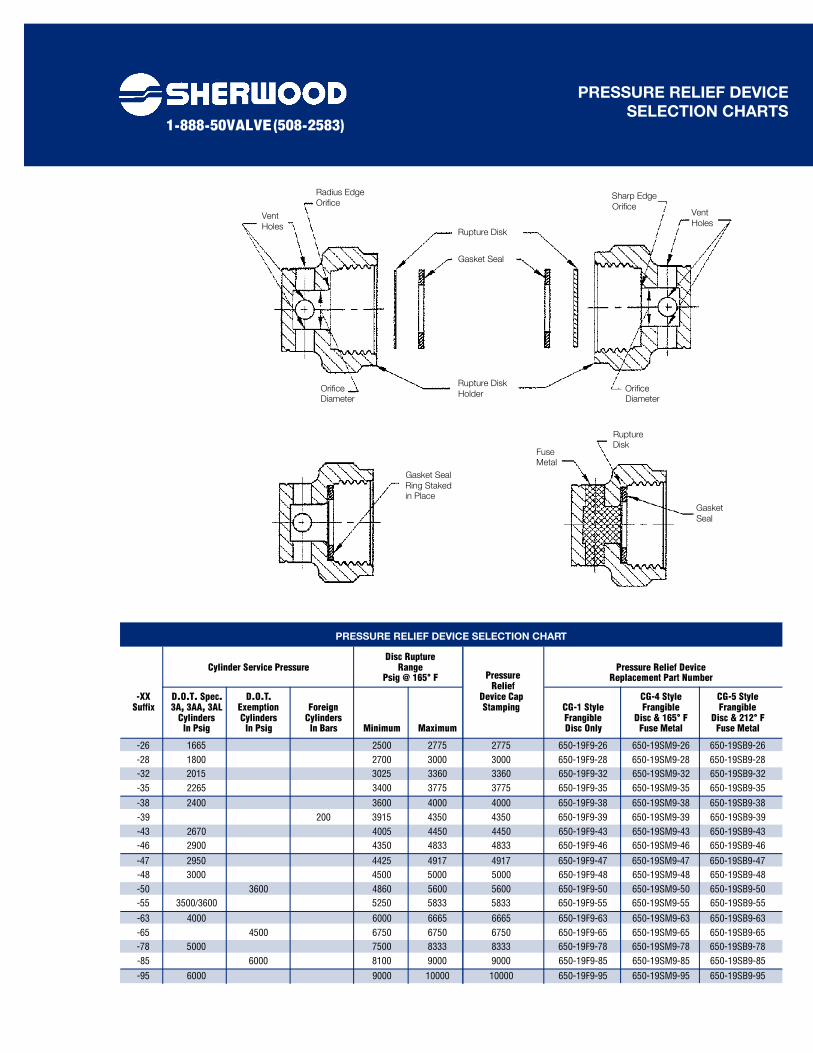
Rupture Disk
Radius Edge
Orifice
Vent
Holes
Vent
Holes
Sharp Edge
Orifice
Orifice
Diameter
Gasket Seal
Ring Staked
in Place
Gasket
Seal
Fuse
Metal
Rupture
Disk
Orifice
Diameter
Rupture Disk
Holder
Gasket Seal
Disc RuptureCylinder Service Pressure Range Pressure Relief Device
Psig @ 165° F Replacement Part Number
-XX D.O.T. Spec. D.O.T. Device Cap CG-4 Style CG-5 Style Suffix 3A, 3AA, 3AL Exemption Foreign Stamping CG-1 Style Frangible Frangible
Cylinders Cylinders Cylinders Frangible Disc & 165° F Disc & 212° F In Psig In Psig In Bars Minimum Maximum Disc Only Fuse Metal Fuse Metal
-26 1665 2500 2775 2775 650-19F9-26 650-19SM9-26 650-19SB9-26-28 1800 2700 3000 3000 650-19F9-28 650-19SM9-28 650-19SB9-28-32 2015 3025 3360 3360 650-19F9-32 650-19SM9-32 650-19SB9-32-35 2265 3400 3775 3775 650-19F9-35 650-19SM9-35 650-19SB9-35
-38 2400 3600 4000 4000 650-19F9-38 650-19SM9-38 650-19SB9-38-39 200 3915 4350 4350 650-19F9-39 650-19SM9-39 650-19SB9-39-43 2670 4005 4450 4450 650-19F9-43 650-19SM9-43 650-19SB9-43-46 2900 4350 4833 4833 650-19F9-46 650-19SM9-46 650-19SB9-46
-47 2950 4425 4917 4917 650-19F9-47 650-19SM9-47 650-19SB9-47-48 3000 4500 5000 5000 650-19F9-48 650-19SM9-48 650-19SB9-48-50 3600 4860 5600 5600 650-19F9-50 650-19SM9-50 650-19SB9-50-55 3500/3600 5250 5833 5833 650-19F9-55 650-19SM9-55 650-19SB9-55
-63 4000 6000 6665 6665 650-19F9-63 650-19SM9-63 650-19SB9-63-65 4500 6750 6750 6750 650-19F9-65 650-19SM9-65 650-19SB9-65-78 5000 7500 8333 8333 650-19F9-78 650-19SM9-78 650-19SB9-78-85 6000 8100 9000 9000 650-19F9-85 650-19SM9-85 650-19SB9-85
-95 6000 9000 10000 10000 650-19F9-95 650-19SM9-95 650-19SB9-95
PRESSURE RELIEF DEVICE SELECTION CHART
PressureRelief
1-888-50VALVE (508-2583)
xx
PRESSURE RELIEF DEVICE
SELECTION CHARTS
Rupture
Disk
Capture by
Gasket Seal
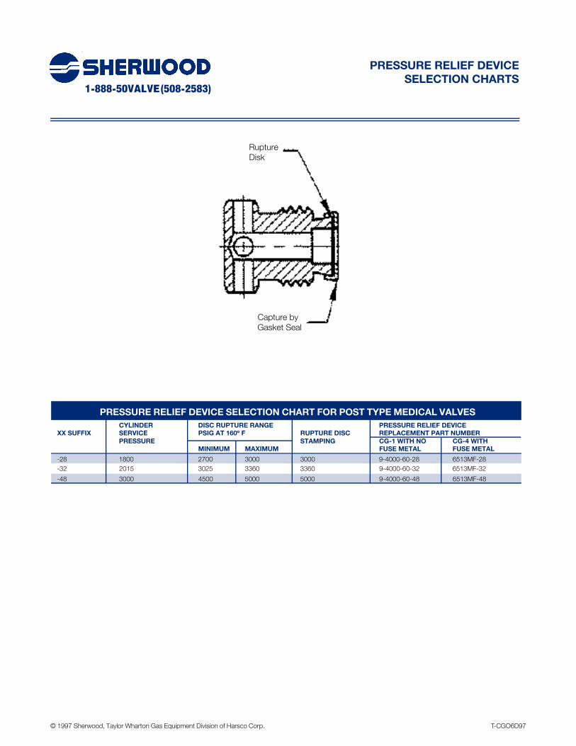
PRESSURE RELIEF DEVICE SELECTION CHART FOR POST TYPE MEDICAL VALVES
CYLINDER DISC RUPTURE RANGE PRESSURE RELIEF DEVICE
XX SUFFIX SERVICE PSIG AT 160º F RUPTURE DISC REPLACEMENT PART NUMBER
PRESSURE STAMPING CG-1 WITH NO CG-4 WITH
MINIMUM MAXIMUM FUSE METAL FUSE METAL
-28 1800 2700 3000 3000 9-4000-60-28 6513MF-28
-32 2015 3025 3360 3360 9-4000-60-32 6513MF-32
-48 3000 4500 5000 5000 9-4000-60-48 6513MF-48
© 1997 Sherwood, Taylor Wharton Gas Equipment Division of Harsco Corp. T-CGO6D97


