Embed Size (px)
Citation preview

H3C SR6600 Routers
ACL and QoS
Configuration Guide
Hangzhou H3C Technologies Co., Ltd. http://www.h3c.com Document Version: 20100930-C-1.08 Product Version: SR6600-CMW520-R2420

Copyright © 2007-2010, Hangzhou H3C Technologies Co., Ltd. and its licensors
All Rights Reserved
No part of this manual may be reproduced or transmitted in any form or by any means without prior written consent of Hangzhou H3C Technologies Co., Ltd.
Trademarks
H3C, , Aolynk, , H3Care,
, TOP G, , IRF, NetPilot, Neocean, NeoVTL, SecPro, SecPoint, SecEngine, SecPath, Comware, Secware, Storware, NQA, VVG, V2G, VnG, PSPT, XGbus, N-Bus, TiGem, InnoVision and HUASAN are trademarks of Hangzhou H3C Technologies Co., Ltd.
All other trademarks that may be mentioned in this manual are the property of their respective owners.
Notice
The information in this document is subject to change without notice. Every effort has been made in the preparation of this document to ensure accuracy of the contents, but all statements, information, and recommendations in this document do not constitute the warranty of any kind, express or implied.

Preface
The H3C SR6600 documentation set includes 13 configuration guides, which describe the software features for the H3C SR6600 Routers and guide you through the software configuration procedures. These configuration guides also provide configuration examples to help you apply software features to different network scenarios.
The ACL and QoS Configuration Guide describes fundamentals and configuration for QoS-related features, including traffic classification, traffic policing, traffic shaping, QoS policy, congestion management, congestion avoidance, priority mapping, hardware congestion management, EACL, DAR, MPLS QoS, and FR QoS.
This preface includes:
Audience
Conventions
About the H3C SR6600 Documentation Set
Obtaining Documentation
Documentation Feedback
Audience
This documentation is intended for:
Network planners
Field technical support and servicing engineers
Network administrators working with the SR6600
Conventions
This section describes the conventions used in this documentation set.
Command conventions
Convention Description
Boldface Bold text represents commands and keywords that you enter literally as shown.
italic Italic text represents arguments that you replace with actual values.
[ ] Square brackets enclose syntax choices (keywords or arguments) that are optional.
{ x | y | ... } Braces enclose a set of required syntax choices separated by vertical bars, from which you select one.
[ x | y | ... ] Square brackets enclose a set of optional syntax choices separated by vertical bars, from which you select one or none.
{ x | y | ... } * Asterisk marked braces enclose a set of required syntax choices separated by vertical bars, from which you select at least one.
[ x | y | ... ] * Asterisk marked square brackets enclose optional syntax choices separated by vertical bars, from which you may select multiple choices or none.
&<1-n> The argument or keyword and argument combination before the ampersand (&) sign can be entered 1 to n times.

Convention Description
# A line that starts with a pound (#) sign is comments.
GUI conventions
Convention Description
Boldface Window names, button names, field names, and menu items are in Boldface. For example, the New User window appears; click OK.
> Multi-level menus are separated by angle brackets. For example, File > Create > Folder.
Symbols
Convention Description
Means reader be extremely careful. Improper operation may cause bodily injury.
Means reader be careful. Improper operation may cause data loss or damage to equipment.
Means an action or information that needs special attention to ensure successful configuration or good performance.
Means a complementary description.
Means techniques helpful for you to make configuration with ease.
Network topology icons
Convention Description
Represents a generic network device, such as a router, switch, or firewall.
Represents a routing-capable device, such as a router or Layer 3 switch.
Represents a generic switch, such as a Layer 2 or Layer 3 switch, or a router that supports Layer 2 forwarding and other Layer 2 features.
About the H3C SR6600 Documentation Set
The H3C SR6600 documentation set includes:
Category Documents Purposes
Marketing brochures Describe product specifications and benefits.
Technology white papers Provide an in-depth description of software features and technologies.
Product description and specifications
Card datasheets Describe card specifications, features, and standards.
Hardware specifications and installation
Compliance and safety manual
Provides regulatory information and the safety instructions that must be followed during installation.

Category Documents Purposes
Installation guide Provides a complete guide to hardware installation and hardware specifications.
Card manuals Provide the hardware specifications of cards.
H3C N68 Cabinet Installation and Remodel Introduction
Guides you through installing and remodeling H3C N68 cabinets.
Configuration guides Describe software features and configuration procedures. Software configuration
Command references Provide a quick reference to all available commands.
H3C SR6608 Release notes Operations and
maintenance H3C SR6602 Release notes
Provide information about the product release, including the version history, hardware and software compatibility matrix, version upgrade information, technical support information, and software upgrading.
Obtaining Documentation
You can access the most up-to-date H3C product documentation on the World Wide Web at http://www.h3c.com.
Click the links on the top navigation bar to obtain different categories of product documentation:
[Technical Support & Documents > Technical Documents] – Provides hardware installation, software upgrading, and software feature configuration and maintenance documentation.
[Products & Solutions] – Provides information about products and technologies, as well as solutions.
[Technical Support & Documents > Software Download] – Provides the documentation released with the software version.
Technical Support
http://www.h3c.com
Documentation Feedback
You can e-mail your comments about product documentation to [email protected].
We appreciate your comments.

i
Table of Contents
1 ACL Configuration·····································································································································1-1 ACL Overview ·········································································································································1-1
ACL Classification ···························································································································1-1 ACL Numbering and Naming ··········································································································1-2 Match Order·····································································································································1-2 ACL Rule Numbering·······················································································································1-3 Implementing Time-Based ACL Rules ····························································································1-4 IPv4 Fragments Filtering with ACLs ································································································1-4 ACL Application ·······························································································································1-4
ACL Configuration Task List ···················································································································1-4 Configuring an ACL·································································································································1-5
Creating a Time Range ···················································································································1-5 Configuring a Basic ACL ·················································································································1-5 Configuring an Advanced ACL ········································································································1-7 Configuring an Ethernet Frame Header ACL ··················································································1-9 Copying an ACL ····························································································································1-10 Enabling ACL Acceleration for an IPv4 ACL ·················································································1-10
Displaying and Maintaining ACLs ·········································································································1-11 ACL Configuration Examples················································································································1-12
IPv4 ACL Configuration Examples ································································································1-12 IPv6 ACL Configuration Example··································································································1-13
2 QoS Overview ············································································································································2-1 Introduction to QoS ·································································································································2-1 QoS Service Models ·······························································································································2-1
Best-Effort Service Model················································································································2-1 IntServ Model ··································································································································2-1 DiffServ Model ·································································································································2-2
QoS Techniques Overview ·····················································································································2-2 Applying QoS Techniques in a Network··························································································2-2 QoS Processing Flow······················································································································2-3
3 QoS Configuration Approaches···············································································································3-1 QoS Configuration Approach Overview··································································································3-1
Non-Policy Approach·······················································································································3-1 Policy Approach·······························································································································3-1
Configuring a QoS Policy························································································································3-1 Defining a Class ······························································································································3-2 Defining a Traffic Behavior ··············································································································3-2 Defining a Policy······························································································································3-3 Applying the QoS Policy··················································································································3-4 Displaying and Maintaining QoS Policies························································································3-6

ii
4 Priority Mapping Configuration················································································································4-1 Priority Mapping Overview ······················································································································4-1
Introduction to Priority Mapping·······································································································4-1 Introduction to Priorities···················································································································4-1 Priority Mapping Tables···················································································································4-2
Priority Mapping Configuration Tasks ·····································································································4-2 Configuring Priority Mapping···················································································································4-2
Configuring a Priority Mapping Table ······························································································4-2 Configuring an Interface to Trust Packet Priority for Priority Mapping ············································4-3 Changing the Port Priority of an Interface ·······················································································4-3
Displaying and Maintaining Priority Mapping··························································································4-4 Priority Mapping Configuration Examples·······························································································4-4
Priority Trust Mode Configuration Example·····················································································4-4 Priority Mapping Table and Priority Marking Configuration Example··············································4-5
5 Traffic Policing and Traffic Shaping Configuration ···············································································5-1 Traffic Policing and Traffic Shaping Overview ························································································5-1
Traffic Evaluation and Token Bucket·······························································································5-1 Traffic Policing ·································································································································5-2 Traffic Shaping ································································································································5-3 Line Rate ·········································································································································5-4
Traffic Policing, Traffic Shaping, and Line Rate Configuration ·······························································5-5 Configuring Traffic Policing ·············································································································5-5 Configuring Traffic Policing in Policy Approach ··············································································5-6 Configuring Traffic Policing in Non-Policy Approach·······································································5-7 Configuring Traffic Shaping·············································································································5-8 Configuring GTS in Policy Approach·······························································································5-8 Configuring GTS in Non-Policy Approach·······················································································5-8 Configuring the Line Rate················································································································5-9
Displaying and Maintaining Traffic Policing, GTS and Line Rate ·························································5-10 Traffic Policing and GTS Configuration Examples················································································5-10
Traffic Policing and GTS Configuration Example··········································································5-10 IP Rate Limiting Configuration Example························································································5-12
6 Congestion Management Configuration ·································································································6-1 Congestion Management Overview········································································································6-1
Causes, Impacts, and Countermeasures of Congestion·································································6-1 Congestion Management Policies···································································································6-2 Congestion Management Technology Comparison ········································································6-7
Configuring FIFO·····································································································································6-8 FIFO Configuration Procedure ········································································································6-8 FIFO Configuration Example···········································································································6-9
Configuring PQ········································································································································6-9 PQ Configuration Procedure ·········································································································6-10 PQ Configuration Example············································································································6-10
Configuring CQ ·····································································································································6-11 Configuration Procedure················································································································6-12

iii
CQ Configuration Example············································································································6-12 Configuring WFQ ··································································································································6-13
Configuration Procedure················································································································6-13 WFQ Configuration Example·········································································································6-13
Configuring CBQ···································································································································6-14 Defining a Class ····························································································································6-14 Defining a Traffic Behavior ············································································································6-15 Defining a QoS Policy····················································································································6-19 Applying the QoS Policy················································································································6-19 Setting the Maximum Reserved Bandwidth as a Percentage of Available Bandwidth ·················6-22 Displaying and Maintaining CBQ···································································································6-22 CBQ Configuration Example ·········································································································6-22
Configuring RTP Priority Queuing·········································································································6-24 Configuration Procedure················································································································6-24 RTP Priority Queuing Configuration Example···············································································6-24
QoS Token Configuration ·····················································································································6-25 QoS Token Configuration Procedure ····························································································6-25 QoS Token Configuration Example·······························································································6-25
Configuring Packet Information Pre-Extraction·····················································································6-26 Configuration Procedure················································································································6-26 Configuration Example ··················································································································6-26
7 Hardware Congestion Management Configuration················································································7-1 Hardware Congestion Management Overview ·······················································································7-1
Causes, Impacts, and Countermeasures ························································································7-1 Congestion Management Techniques·····························································································7-2
Hardware Congestion Management Configuration Approach ································································7-4 Per-Queue Hardware Congestion Management ····················································································7-5
Configuring SP Queuing··················································································································7-5 Configure WRR Queuing·················································································································7-5 Configuring WFQ Queuing ··············································································································7-7
8 Congestion Avoidance······························································································································8-1 Congestion Avoidance Overview ············································································································8-1 Introduction to WRED Configuration·······································································································8-3 Configuring WRED on an Interface·········································································································8-3
Configuration Procedure··················································································································8-3 Configuration Example ····················································································································8-3
Displaying and Maintaining WRED·········································································································8-4 WRED Configuration Example················································································································8-4
9 Traffic Filtering Configuration··················································································································9-1 Traffic Filtering Overview ························································································································9-1 Configuring Traffic Filtering·····················································································································9-1 Traffic Filtering Configuration Example···································································································9-2
Traffic Filtering Configuration Example ···························································································9-2

iv
10 Priority Marking Configuration·············································································································10-1 Priority Marking Overview ·····················································································································10-1 Configuring Priority Marking··················································································································10-1 Priority Marking Configuration Example································································································10-2
Priority Marking Configuration Example ························································································10-2
11 Traffic Redirecting Configuration ········································································································11-1 Traffic Redirecting Overview·················································································································11-1 Configuring Traffic Redirecting ·············································································································11-1 Traffic Redirecting Configuration Examples ·························································································11-2
Redirecting Traffic to an Interface ·································································································11-2
12 EACL Configuration ······························································································································12-1 EACL Overview·····································································································································12-1 EACL Configuration Task List···············································································································12-1 Configuring BT Traffic Limiting··············································································································12-1 EACL Configuration Example ···············································································································12-2
BT Traffic Limiting Configuration Example····················································································12-2 Troubleshooting EACL··························································································································12-4
13 DAR Configuration ································································································································13-1 DAR Overview·······································································································································13-1 Configuring DAR for P2P Traffic Identification······················································································13-1
Loading the P2P Signature File·····································································································13-1 Configuring a P2P Protocol Group ································································································13-2 Enabling P2P Traffic Recognition··································································································13-2 Configuring Protocol Match Criteria ······························································································13-2 Configuring DAR Packet Accounting·····························································································13-2
Displaying and Maintaining DAR ··········································································································13-3 DAR Configuration Examples ···············································································································13-3
P2P Downloading Traffic Blocking Configuration Example···························································13-3
14 Class-Based Accounting Configuration ·····························································································14-1 Class-Based Accounting Overview·······································································································14-1 Configuring Class-Based Accounting ···································································································14-1 Displaying and Maintaining Class-Based Traffic Accounting································································14-2 Class-Based Accounting Configuration Example ·················································································14-2
Class-Based Accounting Configuration Example··········································································14-2
15 Appendix ················································································································································15-1 Appendix A Acronym·····························································································································15-1 Appendix B Default Priority Mapping Tables ························································································15-2 Appendix C Introduction to Packet Precedences ·················································································15-4
IP Precedence and DSCP Values·································································································15-4 802.1p Priority ·······························································································································15-5 802.11e Priority ·····························································································································15-6 EXP Values ···································································································································15-6
16 MPLS QoS Configuration······················································································································16-1 MPLS QoS Overview ····························································································································16-1

v
Configuring MPLS QoS·························································································································16-2 Configuring MPLS CAR·················································································································16-2 Configuring MPLS Priority Marking ·······························································································16-3 Configuring MPLS Congestion Management················································································16-3
MPLS QoS Configuration Example·······································································································16-4 Configuring QoS for Traffic Within a VPN ·····················································································16-4
17 FR QoS Configuration···························································································································17-1 FR QoS Overview ·································································································································17-1
FR QoS··········································································································································17-1 Key Parameters·····························································································································17-1 FR QoS Implementation················································································································17-2
Configuring FR QoS······························································································································17-7 FR QoS Configuration Task List····································································································17-7 Creating and Configuring an FR Class··························································································17-7 Configuring FRTS··························································································································17-8 Configuring FR Traffic Policing······································································································17-9 Configuring FR Congestion Management···················································································17-10 Configuring FR DE Rule List ·······································································································17-10 Configuring FR Queuing··············································································································17-11 Configuring FR Fragmentation ····································································································17-12
Displaying and Maintaining FR QoS···································································································17-13 FR QoS Configuration Examples········································································································17-14
FRTS Configuration Example······································································································17-14 FR Fragmentation Configuration Example··················································································17-14
18 Index ·······················································································································································18-1

1-1
1 ACL Configuration
This chapter includes these sections:
ACL Overview
ACL Configuration Task List
Configuring an ACL
Creating a Time Range
Configuring a Basic ACL
Configuring an IPv4 basic ACL
Configuring an Advanced ACL
Configuring an Ethernet Frame Header ACL
Copying an ACL
Enabling ACL Acceleration for an IPv4 ACL
Displaying and Maintaining ACLs
ACL Configuration Examples
Unless otherwise stated, ACLs refer to both IPv4 and IPv6 ACLs throughout this document.
ACL Overview
An access control list (ACL) is a set of rules (or permit or deny statements) for identifying traffic based on criteria such as the source IP address, destination IP address, and port number.
ACLs are essentially used for packet filtering. A packet filter drops packets that match a deny rule and permits packets that match a permit rule. ACLs are also widely used by many modules, for example, QoS and IP routing, for traffic identification.
This section covers these topics:
ACL Classification
ACL Numbering and Naming
Match Order
Implementing Time-Based ACL Rules
IPv4 Fragments Filtering with ACLs
ACL Application
ACL Classification
The SR6600 supports three categories of ACLs, as shown in Table 1-1.

1-2
Table 1-1 ACL categories
Category ACL number IP version Match criteria
IPv4 Source IPv4 address Basic ACLs 2000 to 2999
IPv6 Source IPv6 address
IPv4 Source/destination IPv4 address, protocols over IPv4, and other Layer 3 and Layer 4 header fields
Advanced ACLs 3000 to 3999
IPv6 Source/destination IPv6 address, protocols over IPv6, and other Layer 3 and Layer 4 header fields
Ethernet frame header ACLs 4000 to 4999 IPv4
Layer 2 header fields, such as source and destination MAC addresses, 802.1p priority, and link layer protocol type
ACL Numbering and Naming
Each ACL category has a unique range of ACL numbers. When creating an ACL, you must assign it a number for identification, and in addition, you can also assign the ACL a name for the ease of identification. After creating an ACL with a name, you can neither rename it nor delete its name.
The number and name for an Ethernet frame header ACL must be globally unique. The number and name for an IPv4 basic or advanced ACL must be unique among all IPv4 ACLs, and for an IPv6 basic or advanced ACL, among all IPv6 ACLs. You can assign an IPv4 ACL the same number and name as an IPv6 ACL.
Match Order
The rules in an ACL are sorted in a certain order. When a packet matches a rule, the device stops the match process and performs the action defined in the rule. If an ACL contains overlapping or conflicting rules, the matching result and action to take depend on the rule order.
Two ACL match orders are available:
config: Sorts ACL rules in ascending order of rule ID. A rule with a lower ID is matched before a rule with a higher ID. If you use this approach, check the rules and their order carefully.
auto: Sorts ACL rules in depth-first order, as described in Table 1-2. The depth-first order varies with ACL categories.
Table 1-2 Sorting ACL rules in depth-first order
ACL category Depth-first rule sorting procedures
IPv4 basic ACL
1) The rule configured with a VPN instance takes precedence. 2) The rule with more 0s in the source IP address wildcard mask takes precedence.
More 0s means a narrower IP address range. 3) The rule with a smaller ID takes precedence.

1-3
ACL category Depth-first rule sorting procedures
IPv4 advanced ACL
1) The rule configured with a VPN instance takes precedence. 2) The rule configured with a specific protocol is prior to a rule with the protocol type
set to IP. IP represents any protocol over IP. 3) The rule with more 0s in the source IP address wildcard mask takes precedence.
More 0s means a narrower IP address range. 4) The rule with more 0s in the destination IP address wildcard mask takes
precedence. 5) The rule with a narrower TCP/UDP service port number range takes precedence.6) The rule with a smaller ID takes precedence.
IPv6 basic ACL 1) The rule configured with a longer prefix for the source IP address takes
precedence. A longer prefix means a narrower IP address range. 2) The rule with a smaller ID takes precedence.
IPv6 advanced ACL
1) The rule configured with a specific protocol is prior to a rule with the protocol type set to IP. IP represents any protocol over IPv6.
2) The rule configured with a longer prefix for the source IPv6 address has a higher priority.
3) The rule configured with a longer prefix for the destination IPv6 address takes precedence.
4) The rule with a narrower TCP/UDP service port number range takes precedence. 5) The rule with a smaller ID takes precedence.
Ethernet frame header ACL
1) The rule with more 1s in the source MAC address mask takes precedence. More 1s means a smaller MAC address.
2) The rule with more 1s in the destination MAC address mask takes precedence. 3) The rule with a smaller ID takes precedence.
A wildcard mask, also called an inverse mask, is a 32-bit binary and represented in dotted decimal notation. In contrast to a network mask, the 0 bits in a wildcard mask represent ‘do care’ bits, while the 1 bits represent 'don’t care bits'. If the 'do care' bits in an IP address identical to the 'do care' bits in an IP address criterion, the IP address matches the criterion. All 'don’t care' bits are ignored. The 0s and 1s in a wildcard mask can be noncontiguous. For example, 0.255.0.255 is a valid wildcard mask. With wildcard masks, you can create more granular match criteria than network masks.
ACL Rule Numbering
What is the ACL rule numbering step If you do not assign an ID for the rule you are creating, the system automatically assigns it a rule ID. The rule numbering step sets the increment by which the system numbers rules automatically. For example, the default ACL rule numbering step is 5. If you do not assign IDs to rules you are creating, they are numbered 0, 5, 10, 15, and so on. The wider the numbering step, the more rules you can insert between two rules.
By introducing a gap between rules rather than contiguously numbering rules, you have the flexibility of inserting rules in an ACL. This feature is important for a config order ACL, where ACL rules are matched in ascending order of rule ID.

1-4
Automatic rule numbering and re-numbering The ID automatically assigned to an ACL rule takes the nearest higher multiple of the numbering step to the current highest rule ID, starting with 0.
For example, if the numbering step is 5 (the default), and there are five ACL rules numbered 0, 5, 9, 10, and 12, the newly defined rule will be numbered 15. If the ACL does not contain any rule, the first rule will be numbered 0.
Whenever the step changes, the rules are renumbered, starting from 0. For example, if there are five rules numbered 5, 10, 13, 15, and 20, changing the step from 5 to 2 causes the rules to be renumbered 0, 2, 4, 6 and 8.
Implementing Time-Based ACL Rules
You can implement ACL rules based on the time of day by applying a time range to them. A time-based ACL rule takes effect only in any time periods specified by the time range.
Two basic types of time range are available:
Periodic time range, which recurs periodically on a day or days of the week.
Absolute time range, which represents only a period of time and does not recur.
You may apply a time range to ACL rules before or after you create it. However, the rules using the time range can take effect only after you define the time range.
IPv4 Fragments Filtering with ACLs
Traditional packet filtering matched only first fragments of IPv4 packets, and allowed all subsequent non-first fragments to pass through. This mechanism resulted in security risks, because attackers may fabricate non-first fragments to attack networks.
To avoids the risks, the H3C ACL implementation:
Filters all fragments by default, including non-first fragments.
Provides ACL-based firewalls with standard and exact match modes for matching ACLs that contain advanced attributes such as TCP/UDP port number and ICMP type. Standard match is the default mode. It considers only Layer 3 attributes. Exact match considers all header attributes defined in IPv4 ACL rules. For more information, see Firewall in the Security Configuration Guide.
ACL Application
You can use ACLs in QoS, firewall, routing, and other technologies for identifying traffic.
ACL Configuration Task List
IPv4 configuration task list Perform the following tasks to configure an IPv4 ACL:
Task Remarks
Creating a Time Range Optional
Configuring an IPv4 basic ACL
Configuring an IPv4 advanced ACL
Configuring an Ethernet Frame Header ACL
Required Perform at least one task.

1-5
Task Remarks
Copying an IPv4 ACL Optional
Enabling ACL Acceleration for an IPv4 ACL Optional
IPv6 ACL configuration task list Perform the following tasks to configure an IPv6 ACL:
Task Remarks
Creating a Time Range Optional
Configuring an IPv6 basic ACL
Configuring an IPv6 Advanced ACL
Required Perform at least one task.
Copying an IPv6 ACL Optional
Configuring an ACL
Creating a Time Range
Follow these steps to create a time range:
To do… Use the command… Remarks
Enter system view system-view ––
Create a time range
time-range time-range-name { start-time to end-time days [ from time1 date1 ] [ to time2 date2 ] | from time1 date1 [ to time2 date2 ] | to time2 date2 }
Required By default, no time range exists.
You may create time ranges identified with the same name. They are regarded as one time range whose active period is the result of ORing periodic ones, ORing absolute ones, and ANDing periodic and absolute ones.
You may create a maximum of 256 uniquely named time ranges, each with up to 32 periodic time ranges and up to 12 absolute time ranges.
Configuring a Basic ACL
Configuring an IPv4 basic ACL IPv4 basic ACLs match packets based on only source IP address.
Follow these steps to configure an IPv4 basic ACL:
To do… Use the command… Remarks
Enter system view system-view ––

1-6
To do… Use the command… Remarks
Create an IPv4 basic ACL and enter its view
acl number acl-number [ name acl-name ] [ match-order { auto | config } ]
Required By default, no ACL exists. IPv4 basic ACLs are numbered in the range 2000 to 2999. You can use the acl name acl-name command to enter the view of an existing named IPv4 ACL.
Configure a description for the IPv4 basic ACL description text
Optional By default, an IPv4 basic ACL has no ACL description.
Set the rule numbering step step step-value Optional 5 by default.
Create or edit a rule
rule [ rule-id ] { deny | permit } [ counting | fragment | logging | source { sour-addr sour-wildcard | any } | time-range time-range-name | vpn-instance vpn-instance-name ] *
Required By default, an IPv4 basic ACL does not contain any rule. To create or edit multiple rules, repeat this step. The logging keyword takes effect only when the module (for example, a firewall) that uses the ACL supports logging.
Configure or edit a rule description rule rule-id comment text Optional By default, an IPv4 ACL rule has no rule description.
Configuring an IPv6 basic ACL Follow these steps to configure an IPv6 basic ACL:
To do… Use the command… Remarks
Enter system view system-view ––
Create an IPv6 basic ACL view and enter its view
acl ipv6 number acl6-number [ name acl6-name ] [ match-order { auto | config } ]
Required By default, no ACL exists. IPv6 basic ACLs are numbered in the range 2000 to 2999. You can use the acl ipv6 name acl6-name command to enter the view of an existing named IPv6 ACL.
Configure a description for the IPv6 basic ACL description text
Optional By default, an IPv6 basic ACL has no ACL description.
Set the rule numbering step step step-value Optional 5 by default

1-7
To do… Use the command… Remarks
Create or edit a rule
rule [ rule-id ] { deny | permit } [ counting | fragment | logging | source { ipv6-address prefix-length | ipv6-address/prefix-length | any } | time-range time-range-name ] *
Required By default, an IPv6 basic ACL does not contain any rule. To create or edit multiple rules, repeat this step. The logging keyword takes effect only when the module (for example, a firewall) using the ACL supports logging.
Configure or edit a rule description rule rule-id comment text Optional By default, an IPv6 basic ACL rule has no rule description.
Configuring an Advanced ACL
Configuring an IPv4 advanced ACL IPv4 advanced ACLs match packets based on source and destination IP addresses, protocols over IP, and other protocol header information, such as TCP/UDP source and destination port numbers, TCP flags, ICMP message types, and ICMP message codes.
IPv4 advanced ACLs also allow you to filter packets based on three priority criteria: type of service (ToS), IP precedence, and differentiated services codepoint (DSCP) priority.
Compared with IPv4 basic ACLs, IPv4 advanced ACLs allow of more flexible and accurate filtering.
Follow these steps to configure an IPv4 advanced ACL:
To do… Use the command… Remarks
Enter system view system-view ––
Create an IPv4 advanced ACL and enter its view
acl number acl-number [ name acl-name ] [ match-order { auto | config } ]
Required By default, no ACL exists. IPv4 advanced ACLs are numbered in the range 3000 to 3999. You can use the acl name acl-name command to enter the view of an existing named IPv4 ACL.
Configure a description for the IPv4 advanced ACL description text
Optional By default, an IPv4 advanced ACL has no ACL description.
Set the rule numbering step step step-value Optional 5 by default.

1-8
To do… Use the command… Remarks
Create or edit a rule
rule [ rule-id ] { deny | permit } protocol [ { { ack ack-value | fin fin-value | psh psh-value | rst rst-value | syn syn-value | urg urg-value } * | established } | counting | destination { dest-addr dest-wildcard | any } | destination-port operator port1 [ port2 ] | dscp dscp | fragment | icmp-type { icmp-type icmp-code | icmp-message } | logging | precedence precedence | reflective | source { sour-addr sour-wildcard | any } | source-port operator port1 [ port2 ] | time-range time-range-name | tos tos | vpn-instance vpn-instance-name ] *
Required By default, an IPv4 advanced ACL does not contain any rule. To create or edit multiple rules, repeat this step. The logging keyword takes effect only when the module (for example, a firewall) using the ACL supports logging.
Configure or edit a rule description rule rule-id comment text Optional By default, an IPv4 advanced ACL rule has no rule description.
Configuring an IPv6 Advanced ACL IPv6 advanced ACLs match packets based on the source IPv6 address, destination IPv6 address, protocol carried over IPv6, and other protocol header fields such as the TCP/UDP source port number, TCP/UDP destination port number, ICMP message type, and ICMP message code.
Compared with IPv6 basic ACLs, they allow of more flexible and accurate filtering.
Follow these steps to configure an IPv6 advanced ACL:
To do… Use the command… Remarks
Enter system view system-view ––
Create an IPv6 advanced ACL and enter its view
acl ipv6 number acl6-number [ name acl6-name ] [ match-order { auto | config } ]
Required By default, no ACL exists. IPv6 advanced ACLs are numbered in the range 3000 to 3999. You can use the acl ipv6 name acl6-name command to enter the view of an existing named IPv6 ACL.
Configure a description for the IPv6 advanced ACL description text
Optional By default, an IPv6 advanced ACL has no ACL description.
Set the rule numbering step step step-value Optional 5 by default.

1-9
To do… Use the command… Remarks
Create or edit a rule
rule [ rule-id ] { deny | permit } protocol [ { { ack ack-value | fin fin-value | psh psh-value | rst rst-value | syn syn-value | urg urg-value } * | established } | counting | destination { dest dest-prefix | dest/dest-prefix | any } | destination-port operator port1 [ port2 ] | dscp dscp | flow-label flow-label-value | fragment | icmp6-type { icmp6-type icmp6-code | icmp6-message } | logging | source { source source-prefix | source/source-prefix | any } | source-port operator port1 [ port2 ] | time-range time-range-name ] *
Required By default IPv6 advanced ACL does not contain any rule. To create or edit multiple rules, repeat this step. The logging keyword takes effect only when the module (for example, a firewall) using the ACL supports logging.
Configure or edit a rule description rule rule-id comment text
Optional By default, an IPv6 advanced ACL rule has no rule description.
Configuring an Ethernet Frame Header ACL
Ethernet frame header ACLs, also called Layer 2 ACLs, match packets based on Layer 2 protocol header fields such as source MAC address, destination MAC address, 802.1p priority (VLAN priority), and link layer protocol type.
Follow these steps to configure an Ethernet frame header ACL:
To do… Use the command… Remarks
Enter system view system-view ––
Create an Ethernet frame header ACL and enter its view
acl number acl-number [ name acl-name ] [ match-order { auto | config } ]
Required By default, no ACL exists. Ethernet frame header ACLs are numbered in the range 4000 to 4999. You can use the acl name acl-name command to enter the view of an existing named Ethernet frame header ACL.
Configure a description for the Ethernet frame header ACL description text
Optional By default, an Ethernet frame header ACL has no ACL description.
Set the rule numbering step step step-value Optional 5 by default.
Create or edit a rule
rule [ rule-id ] { deny | permit } [ cos vlan-pri | counting | dest-mac dest-addr dest-mask | { lsap lsap-type lsap-type-mask | type protocol-type protocol-type-mask } | source-mac sour-addr source-mask | time-range time-range-name ] *
Required By default, an Ethernet frame header ACL does not contain any rule. To create or edit multiple rules, repeat this step.

1-10
To do… Use the command… Remarks
Configure or edit a rule description rule rule-id comment text
Optional By default, an Ethernet frame header ACL rule has no rule description.
Copying an ACL
You can create an ACL by copying an existing ACL. The new ACL has the same properties and content as the source ACL except the ACL number and name.
To successfully copy an IPv4 or IPv6 ACL, ensure that:
The destination ACL number is from the same category as the source ACL number.
The source IPv4 or IPv6 ACL already exists but the destination IPv4 or IPv6 ACL does not.
Copying an IPv4 ACL Follow these steps to copy an IPv4 ACL:
To do… Use the command… Remarks
Enter system view system-view —
Copy an existing IPv4 ACL to create a new IPv4 ACL
acl copy { source-acl-number | name source-acl-name } to { dest-acl-number | name dest-acl-name }
Required
Copying an IPv6 ACL Follow these steps to copy an IPv6 ACL:
To do… Use the command… Remarks
Enter system view system-view —
Copy an existing IPv6 ACL to generate a new one of the same category
acl ipv6 copy { source-acl6-number | name source-acl6-name } to { dest-acl6-number | name dest-acl6-name }
Required
Enabling ACL Acceleration for an IPv4 ACL
ACL acceleration speeds up ACL lookup. Its acceleration effect increases with the number of ACL rules. ACL acceleration uses memory. To achieve the best trade-off between memory and ACL processing performance, H3C recommends you enable ACL acceleration for large ACLs, for example, ACLs that contain more than 50 rules.
For example, when you use a large ACL for a session-based service, such as NAT or ASPF, you can enable ACL acceleration to avoid session timeouts caused by ACL processing delays.
Enable ACL acceleration in an ACL after you have finished editing ACL rules. ACL acceleration always uses ACL criteria that have been set before it is enabled for rule matching. It does not synchronize with any subsequent match criterion changes.
1-11
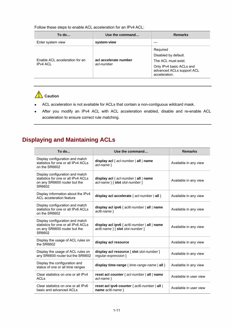
Follow these steps to enable ACL acceleration for an IPv4 ACL:
To do… Use the command… Remarks
Enter system view system-view —
Enable ACL acceleration for an IPv4 ACL
acl accelerate number acl-number
Required Disabled by default. The ACL must exist. Only IPv4 basic ACLs and advanced ACLs support ACL acceleration.
ACL acceleration is not available for ACLs that contain a non-contiguous wildcard mask.
After you modify an IPv4 ACL with ACL acceleration enabled, disable and re-enable ACL acceleration to ensure correct rule matching.
Displaying and Maintaining ACLs
To do... Use the command… Remarks
Display configuration and match statistics for one or all IPv4 ACLs on the SR6602
display acl { acl-number | all | name acl-name } Available in any view
Display configuration and match statistics for one or all IPv4 ACLs on any SR6600 router but the SR6602
display acl { acl-number | all | name acl-name } [ slot slot-number ] Available in any view
Display information about the IPv4 ACL acceleration feature display acl accelerate { acl-number | all } Available in any view
Display configuration and match statistics for one or all IPv6 ACLs on the SR6602
display acl ipv6 { acl6-number | all | name acl6-name } Available in any view
Display configuration and match statistics for one or all IPv6 ACLs on any SR6600 router but the SR6602
display acl ipv6 { acl6-number | all | name acl6-name } [ slot slot-number ] Available in any view
Display the usage of ACL rules on the SR6602 display acl resource Available in any view
Display the usage of ACL rules on any SR6600 router but the SR6602
display acl resource [ slot slot-number ] regular-expression ] Available in any view
Display the configuration and status of one or all time ranges display time-range { time-range-name | all } Available in any view
Clear statistics on one or all IPv4 ACLs
reset acl counter { acl-number | all | name acl-name } Available in user view
Clear statistics on one or all IPv6 basic and advanced ACLs
reset acl ipv6 counter { acl6-number | all | name acl6-name } Available in user view

1-12
ACL Configuration Examples
IPv4 ACL Configuration Examples
Network Requirements A company interconnects its departments through Device. Configure an ACL to deny access from all departments except for the President’s office to the salary server during working hours (from 8:00 to 18:00) on working days.
Figure 1-1 Network diagram for IPv4 ACL configuration
Configuration Procedure # Create a periodic time range from 8:00 to 18:00 on working days. <DeviceA> system-view
[DeviceA] time-range work 8:0 to 18:0 working-day
# Create an IPv4 advanced ACL numbered 3000 and configure two rules in the ACL. One rule allows access from the President’s office to the salary server, and the other denies access from other departments to the salary server in the time range. [DeviceA] acl number 3000
[DeviceA-acl-adv-3000] rule permit ip source 192.168.1.0 0.0.0.255 destination 192.168.0.100 0
[DeviceA-acl-adv-3000] rule deny ip source any destination 192.168.0.100 0 time-range work
[DeviceA-acl-adv-3000] quit
# Enable IPv4 firewall, and apply IPv4 ACL 3000 to filter outgoing packets on interface GigabitEthernet 1/0/1. [DeviceA] firewall enable
[DeviceA] interface gigabitethernet 1/0/1
[DeviceA-GigabitEthernet1/0/1] firewall packet-filter 3000 outbound
Verification # Display the configuration and match statistics for IPv4 ACL 3000. [DeviceA] display acl 3000
Advanced ACL 3000, named -none-, 2 rules,
ACL's step is 5
rule 0 permit ip source 192.168.1.0 0.0.0.255 destination 192.168.0.100 0

1-13
rule 5 deny ip destination 192.168.0.100 0 time-range work (Inactive)
IPv6 ACL Configuration Example
Network Requirements A company interconnects its departments through Device. Configure an ACL to deny access from all departments but the President’s office to the salary server during working hours (from 8:00 to 18:00) on working days.
Figure 1-2 Network diagram for IPv6 ACL configuration
Configuration Procedure # Create a periodic time range from 8:00 to 18:00 on working days. <DeviceA> system-view
[DeviceA] time-range work 8:0 to 18:0 working-day
# Create an IPv6 advanced ACL numbered 3000 and configure two rules in the ACL. One rule allows access from the President’s office to the salary server, and the other denies access from other departments to the salary server in the time range. [DeviceA] acl ipv6 number 3000
[DeviceA-acl6-adv-3000] rule permit ipv6 source 1001:: 4 destination 1000::100 128
[DeviceA-acl6-adv-3000] rule deny ipv6 source any destination 1000::100 128 time-range work
[DeviceA-acl6-adv-3000] quit
# Enable IPv6 firewall, and apply IPv6 ACL 3000 to filter outgoing packets on interface GigabitEthernet 1/0/1. [DeviceA] firewall ipv6 enable
[DeviceA] interface gigabitethernet 1/0/1
[DeviceA-GigabitEthernet1/0/1] firewall packet-filter ipv6 3000 outbound
Verification # Display the configuration and match statistics for IPv6 ACL 3000. [DeviceA] display acl ipv6 3000
Advanced IPv6 ACL 3000, named -none-, 2 rules,
ACL's step is 5
rule 0 permit ipv6 source 1000::/4 destination 1000::100/128
rule 5 deny ipv6 destination 1000::100/128 time-range work (Inactive)

2-1
2 QoS Overview
This chapter includes these sections:
Introduction to QoS
QoS Service Models
QoS Techniques Overview
Introduction to QoS
In data communications, Quality of Service (QoS) is the ability of a network to provide differentiated service guarantees for diverse traffic in terms of bandwidth, delay, jitter, and drop rate.
Network resources are always scarce. The contention for resources demands that QoS prioritize important traffic flows over trivial traffic flows. When making a QoS scheme, a network administrator must consider the characteristics of various applications to balance the interests of diversified users and fully utilize network resources.
The subsequent section describes some typical QoS service models and widely used mature QoS techniques. By appropriately using these techniques, you can improve QoS effectively.
QoS Service Models
This section covers three typical QoS service models:
Best-Effort Service Model
IntServ Model
DiffServ Model
Best-Effort Service Model
Best effort is a single service model and also the simplest service model. In the best effort service model, the network does its best to deliver packets but does not guarantee delay or reliability.
The best-effort service model is the default model in the Internet and applies to most network applications. It uses the first in first out (FIFO) queuing mechanism.
IntServ Model
The integrated service (IntServ) model is a multiple-service model that can accommodate multiple QoS requirements. It provides the most granularly differentiated QoS by definitely identifying and guaranteeing QoS for each data flow.
In the IntServ model, an application must request a specific kind of service from the network before it sends data. IntServ signals the service request with the Resource Reservation Protocol (RSVP). All nodes that receive the request reserve resources as requested and maintain state information for the application flow.

2-2
The IntServ model demands high storage and processing capabilities, because it requires that all nodes along the transmission path maintain resource state information for each flow. The model is suitable for small-sized or edge networks, but not large-sized networks, for example, the core layer of the Internet, where billions of flows are present.
For more information about RSVP, see MPLS TE in the MPLS Configuration Guide.
DiffServ Model
The differentiated services (DiffServ) model is a multiple-service model that can satisfy diverse QoS requirements. Unlike IntServ, DiffServ does not require an application to signal the network to reserve resources before sending data. DiffServ is easy to implement and extend.
All QoS techniques in this document are based on the Diff-Serv model.
QoS Techniques Overview
The QoS techniques fall into traffic classification, traffic policing, traffic shaping, line rate, congestion management, and congestion avoidance. The following part briefly introduces these QoS techniques.
Applying QoS Techniques in a Network
Figure 2-1 Position of the QoS techniques in a network
As shown in Figure 2-1, traffic classification, traffic shaping, traffic policing, congestion management, and congestion avoidance mainly implement the following functions:
Traffic classification uses certain match criteria to assign packets with the same characteristics to a class. Based on classes, you can provide differentiated services.

2-3
Traffic policing polices flows entering or leaving a router, and imposes penalties on traffic flows that exceed the pre-set threshold to prevent aggressive use of network resources. You can apply traffic policing to both incoming and outgoing traffic of a port.
Traffic shaping proactively adapts the output rate of traffic to the network resources available on the downstream router to eliminate packet drops. Traffic shaping usually applies to the outgoing traffic of a port.
Congestion management provides a resource scheduling policy to determine the packet forwarding sequence when congestion occurs. Congestion management is usually applied to the outgoing traffic of a port.
Congestion avoidance monitors the network resource usage and is usually applied to the outgoing traffic of a port. As congestion worsens, congestion avoidance actively reduces the queue length by dropping packets.
QoS Processing Flow
Figure 2-2 QoS processing flow
...
Figure 2-2 briefly describes how the QoS module processes traffic:
1) Traffic classifier identifies and classifies traffic for subsequent QoS actions.
2) The QoS module takes various QoS actions on classified traffic as configured, depending on the traffic processing phase and network status. For example, you may configure the QoS module to perform traffic policing for incoming traffic, traffic shaping for outgoing traffic, congestion avoidance before congestion occurs, and congestion management when congestion occurs.

3-1
3 QoS Configuration Approaches
This chapter includes these sections:
QoS Configuration Approach Overview
Configuring a QoS Policy
QoS Configuration Approach Overview
Two approaches are available for configuring QoS: Non-Policy Approach and Policy Approach.
Some features support both approaches, but some support only one.
Non-Policy Approach
In non-policy approach, you configure QoS service parameters directly without using a QoS policy. For example, you can use the line rate feature to set a rate limit on an interface without using a QoS policy.
Policy Approach
In policy approach, you configure QoS service parameters by using QoS policies. A QoS policy defines the shaping, policing, or other QoS actions to take on different classes of traffic. It is a set of class-behavior associations.
A class is a set of match criteria for identifying traffic. It uses the AND or OR operator:
If the operator is AND, a packet must match all the criteria to match the class.
If the operator is OR, a packet matches the class if it matches any of the criteria in the class.
A traffic behavior defines a set of QoS actions to take on packets, such as priority marking and redirect.
By associating a traffic behavior with a class in a QoS policy, you apply the specific set of QoS actions to the class of traffic.
Configuring a QoS Policy
Figure 3-1 shows how to configure a QoS policy.

3-2
Figure 3-1 QoS policy configuration procedure
Define a class
Define a behavior
Define a policy
Apply the policy
To an interface or PVC
To a VLAN
To online users
Defining a Class
To define a class, specify its name and then configure the match criteria in class view.
Follow these steps to define a class:
To do… Use the command… Remarks
Enter system view system-view —
Create a class and enter class view traffic classifier tcl-name [ operator { and | or } ]
Required By default, the operator of a class is AND.
Configure match criteria if-match [ not ] match-criteria Required
Defining a Traffic Behavior
A traffic behavior is a set of QoS actions (such as traffic filtering, shaping, policing, and priority marking) to take on a class of traffic. To define a traffic behavior, first create it and then configure QoS actions (such as priority marking and traffic redirecting) in traffic behavior view.
Follow these steps to define a traffic behavior:
To do… Use the command… Remarks
Enter system view system-view —
Create a traffic behavior and enter traffic behavior view traffic behavior behavior-name Required

3-3
To do… Use the command… Remarks
Configure actions in the traffic behavior
See the following chapters based on the purpose of the traffic behavior: traffic policing, traffic filtering, traffic redirecting, priority marking, traffic accounting, and so on.
Defining a Policy
Configuring a parent policy You associate a behavior with a class in a QoS policy to perform the actions defined in the behavior for the class of packets.
Follow these steps to associate a class with a behavior in a policy:
To do… Use the command… Remarks
Enter system view system-view —
Create a policy and enter policy view
qos policy policy-name Required
Associate a class with a behavior in the policy
classifier tcl-name behavior behavior-name Required
The QoS module ignores ACL match clauses that contain a deny rule. If a deny rule is encountered when examining an ACL match clause, the QoS module ignores the clause and moves to the next one.
To use a Layer 2 ACL in a QoS policy, do not configure any rule with the lasp keyword in the ACL.
Configuring QoS policy nesting You can reference a QoS policy in a traffic behavior to re-classify the traffic class associated with the behavior and take action on the re-classified traffic as defined in the policy. The QoS policy referenced in the traffic behavior is called the child policy; the QoS policy that references the behavior is called the parent policy.
Follow these steps to nest a child QoS policy in a parent QoS policy:
To do… Use the command… Remarks
Enter system view system-view —
Create a class for the parent policy and enter class view
traffic classifier tcl-name [ operator { and | or } ] —
Configure match criteria if-match [ not ] match-criteria —
Quit class view quit ––
Create a behavior for the parent policy and enter behavior view
traffic behavior behavior-name —

3-4
To do… Use the command… Remarks
Nest the child QoS policy traffic-policy policy-name
Required The QoS policy specified for the policy-name argument must already exist.
Quit traffic behavior view quit ––
Create the parent policy and enter parent policy view
qos policy policy-name —
Associate the class with the behavior in the parent policy
classifier tcl-name behavior behavior-name —
To nest QoS policies successfully, follow these guidelines:
If class-based queuing (CBQ) is configured in the child policy, configure generic traffic shaping (GTS) in the parent policy and ensure that the GTS bandwidth configured in the parent policy is equal to or greater than the CBQ bandwidth configured in the child policy.
If GTS bandwidth in the parent policy is configured in percentage, the CBQ bandwidth in the child policy must be also configured in percentage; if it is configured as an absolute number, the CBQ bandwidth in the child policy can be configured in either percentage or as an absolute number.
GTS cannot be configured in the child policy.
Applying the QoS Policy
You can apply a QoS policy to different occasions:
Applied to an interface or permanent virtual circuit (PVC), the policy takes effect on the traffic sent or received on the interface or PVC.
Applied to a user profile, the policy takes effect on the traffic sent or received by the online users of the user profile.
Applied to a VLAN, the policy takes effect on the traffic sent or received on all ports in the VLAN. (applicable to the SR6604, the SR6608, and the SR6616)
Applying the QoS policy to an interface or PVC A policy can be applied to multiple interfaces or PVCs, but only one policy can be applied in one direction (inbound or outbound) of an interface or PVC.
Follow these steps to apply the QoS policy to an interface or PVC:
To do… Use the command… Remarks
Enter system view system-view —

3-5
To do… Use the command… Remarks
Enter interface view
interface interface-type interface-number
Enter port group view port-group manual port-group-name
interface atm interface-number
Enter interface view, port group view, or PVC view
Enter PVC view pvc vpi/vci
Use one of the approaches Settings in interface view take effect on the current interface. Settings in port group view take effect on all ports in the port group. Settings in PVC view take effect on the current PVC.
Apply the policy to the interface/port group/PVC
qos apply policy policy-name { inbound | outbound } Required
The QoS policy applied to the outgoing traffic on an interface or PVC does not regulate local packets. Local packets refer to the critical protocol packets sent by the local system for maintaining the normal operation of the router. To avoid drop of local packets, QoS does not process them. Commonly used local packets include link maintenance packets, IS-IS packets, OSPF packets, RIP packets, BGP packets, LDP packets, RSVP packets, and SSH packets.
Applying the QoS policy to online users A QoS policy can be applied to multiple online users, but only one policy can be applied in one direction of each online user. To modify a QoS policy already applied in a certain direction, remove the QoS policy application first.
Follow these steps to apply the QoS policy to online users:
To do… Use the command… Remarks
Enter system view system-view —
Enter user profile view user-profile profile-name
Required The configuration made in user profile view takes effect when the user-profile is activated and the users of the user profile are online. For more information about user profiles, see User Profile in the Security Configuration Guide.
Apply the QoS policy qos apply policy policy-name { inbound | outbound }
Required Use the inbound keyword to apply the QoS policy to the traffic received by the online users. Use the outbound keyword to apply the QoS policy to the traffic sent by the online users.
Return to system view quit —
Activate the user profile user-profile profile-name enable Required Inactive by default

3-6
You cannot modify or remove the QoS policy used by an active user profile. However, you can edit any ACL referenced by the QoS policy when the user profile has no online users.
The QoS policy applied to a user profile supports only the remark, car, and filter actions.
Do not apply a null policy to a user profile. The user profile using a null policy cannot be activated.
Applying the QoS policy to a VLAN You can apply a QoS policy to a VLAN to regulate traffic of the VLAN.
Follow these steps to apply the QoS policy to a VLAN:
To do… Use the command… Remarks
Enter system view system-view —
Apply the QoS policy to VLANs qos vlan-policy policy-name vlan vlan-id-list { inbound | outbound } Required
You cannot apply QoS policies to dynamic VLANs, for example, VLANs created by GVRP.
VLAN QoS policies are applied globally to all interface cards. If the hardware resources of an interface card are insufficient, applying a QoS policy to VLANs may fail on the interface card. In this case, the system does not automatically roll back the QoS policy configuration already applied to the main processing unit or other interface cards. To ensure consistency, use the undo qos vlan-policy vlan command to manually remove the QoS policy configuration applied to them.
Displaying and Maintaining QoS Policies
To do… Use the command… Remarks
Display traffic class configuration display traffic classifier { system-defined | user-defined } [ tcl-name ]
Available in any view
Display traffic behavior configuration
display traffic behavior { system-defined | user-defined } [ behavior-name ]
Available in any view
Display system-defined or user-defined QoS policy configuration
display qos policy { system-defined | user-defined } [ policy-name [ classifier tcl-name ] ]
Available in any view
Display QoS policy configuration on the specified or all interfaces/PVCs
display qos policy interface [ interface-type interface-number ] [ inbound | outbound ] [ pvc { pvc-name [ vpi/vci ] | vpi/vci } ]
Available in any view

3-7
To do… Use the command… Remarks
Display VLAN QoS policy configuration
display qos vlan-policy { name policy-name | vlan vlan-id } [ slot slot-number ]
Available in any view Only available on the SR6604/6608/6616
Clear VLAN QoS policy statistics reset qos vlan-policy [ vlan vlan-id ] [ inbound | outbound ]
Available in user view Only available on the SR6604/6608/6616

4-1
4 Priority Mapping Configuration
The features in this chapter are available only on routers that have a SAP interface card.
This chapter includes these sections:
Priority Mapping Overview
Priority Mapping Configuration Tasks
Configuring Priority Mapping
Displaying and Maintaining Priority Mapping
Priority Mapping Configuration Examples
Priority Mapping Overview
Introduction to Priority Mapping
When a packet enters a router, the router assigns a set of QoS priority parameters to the packet based on a certain priority field carried in the packet or the port priority of the incoming port, depending on your configuration. This process is called priority mapping. During this process, the router may modify the priority of the packet, depending on router status. The set of QoS priority parameters decides the scheduling priority and forwarding priority of the packet.
Priority mapping is implemented with priority mapping tables and involves priorities such as 802.11e priority, 802.1p priority, DSCP, EXP, IP precedence, local precedence, and drop precedence.
Introduction to Priorities
There are two types of priority: priorities carried in packets and priorities locally assigned for scheduling only.
The packet carried priorities include 802.1p priority, DSCP precedence, IP precedence, EXP, and so on. These priorities have global significance and affect the forwarding priority of packets across the network. For detailed description of these priorities, see Appendix C Introduction to Packet Precedences.
The locally assigned priorities have only local significance. They are assigned by the router for scheduling only. These priorities include the local precedence and drop precedence, as follows.
Local precedence is used for queuing. A local precedence value corresponds to an output queue. A packet with higher local precedence is assigned to a higher priority output queue to be preferentially scheduled.
Drop precedence is used for making packet drop decisions. Packets with the highest drop precedence are dropped preferentially.
4-2
Priority Mapping Tables
The router provides various types of priority mapping tables, or rather, priority mappings. By looking up a priority mapping table, the router decides which priority value is to assign to a packet for subsequent packet processing.
The default priority mapping tables (as shown in Appendix B Default Priority Mapping Tables) are available for priority mapping. Generally, they are sufficient for priority mapping. If a default priority mapping table cannot meet your requirements, you can modify the priority mapping table as required.
Priority Mapping Configuration Tasks
You can configure priority mapping in two approaches:
Configuring priority trust mode. In this approach, you can configure a port to look up the priority mapping tables based on a certain priority such as 802.1p carried in incoming packets. If no packet priority is trusted, the port priority of the incoming port is used.
Changing port priority. By default, all ports are assigned the port priority of zero. By changing the port priority of a port, you can change the priority of the incoming packets on the port.
You are recommended to plan QoS throughout the network before making QoS configuration.
Complete the following task to configure priority mapping:
Task Remarks
Configuring a Priority Mapping Table Optional
Configuring an Interface to Trust Packet Priority for Priority Mapping Optional
Changing the Port Priority of an Interface Optional
Configuring Priority Mapping
Configuring a Priority Mapping Table
The router provides various types of priority mapping table, as listed below.
dot1p-dp: 802.1p-to-drop priority mapping table.
dot1p-exp: 802.1p-to-EXP priority mapping table.
dot1p-lp: 802.1p-to-local priority mapping table.
dscp-dot1p: DSCP-to-802.1p priority mapping table, which applies to only IP packets.
dscp-dp: DSCP-to-drop priority mapping table, which applies to only IP packets.
dscp-dscp: DSCP-to-DSCP priority mapping table, which applies to only IP packets.
exp-dot1p: EXP-to-802.1p priority mapping table.
exp-dp: EXP-to-drop priority mapping table.
Follow these steps to configure a priority mapping table:
To do… Use the command… Remarks
Enter system view system-view —
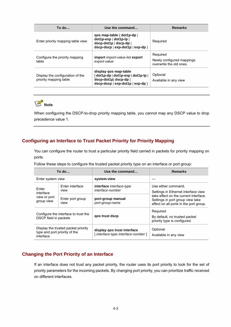
4-3
To do… Use the command… Remarks
Enter priority mapping table view
qos map-table { dot1p-dp | dot1p-exp | dot1p-lp | dscp-dot1p | dscp-dp | dscp-dscp | exp-dot1p | exp-dp }
Required
Configure the priority mapping table
import import-value-list export export-value
Required Newly configured mappings overwrite the old ones.
Display the configuration of the priority mapping table
display qos map-table [ dot1p-dp | dot1p-exp | dot1p-lp | dscp-dot1p| dscp-dp | dscp-dscp | exp-dot1p | exp-dp ]
Optional Available in any view
When configuring the DSCP-to-drop priority mapping table, you cannot map any DSCP value to drop precedence value 1.
Configuring an Interface to Trust Packet Priority for Priority Mapping
You can configure the router to trust a particular priority field carried in packets for priority mapping on ports.
Follow these steps to configure the trusted packet priority type on an interface or port group:
To do… Use the command… Remarks
Enter system view system-view —
Enter interface view
interface interface-type interface-number Enter
interface view or port group view Enter port group
view port-group manual port-group-name
Use either command. Settings in Ethernet interface view take effect on the current interface. Settings in port group view take effect on all ports in the port group.
Configure the interface to trust the DSCP field in packets qos trust dscp
Required By default, no trusted packet priority type is configured.
Display the trusted packet priority type and port priority of the interface
display qos trust interface [ interface-type interface-number ]
Optional Available in any view
Changing the Port Priority of an Interface
If an interface does not trust any packet priority, the router uses its port priority to look for the set of priority parameters for the incoming packets. By changing port priority, you can prioritize traffic received on different interfaces.

4-4
Follow these steps to change the port priority of an interface:
To do… Use the command… Remarks
Enter system view system-view —
Enter interface view
interface interface-type interface-number Enter
interface view or port group view Enter port group
view port-group manual port-group-name
Use either command. Settings in Ethernet interface view take effect on the current interface. Settings in port group view take effect on all ports in the port group.
Set the port priority of the interface qos priority priority-value Required The default is 0.
Display the trusted packet priority type and port priority of the interface
display qos trust interface [ interface-type interface-number ]
Optional Available in any view
Displaying and Maintaining Priority Mapping
To do… Use the command… Remarks
Display priority mapping table configuration
display qos map-table [ dot1p-dp | dot1p-dscp | dot1p-lp | dscp-dot1p | dscp-dp | dscp-dscp | exp-dot1p | exp-dp ]
Available in any view
Display the trusted packet priority type and port priority of a port
display qos trust interface [ interface-type interface-number ] Available in any view
Priority Mapping Configuration Examples
Priority Trust Mode Configuration Example
Network requirements As shown in Figure 4-1, Device A is connected through its GigabitEthernet 1/0/1 port to Device. The IP precedence of its traffic is 3. Device B is connected through its GigabitEthernet 1/0/2 port to Device. The IP precedence of its traffic is 1.
Make configurations to have Device preferentially process packets from Device A to Server when GigabitEthernet 1/0/3 of Device is congested.

4-5
Figure 4-1 Network diagram for priority trust mode configuration
Configuration procedure 1) Approach 1: configure Device to trust packet priority
# Configure GigabitEthernet 1/0/1 and GigabitEthernet 1/0/2 to use DSCP values in incoming packets for priority mapping. <Device> system-view
[Device] interface gigabitethernet 1/0/1
[Device-GigabitEthernet1/0/1] qos trust dscp
[Device-GigabitEthernet1/0/1] quit
[Device] interface ethernet 1/0/2
[Device-Ethernet1/0/2] qos trust dscp
[Device-Ethernet1/0/2] quit
2) Approach 2: configure Device to trust port priority
# Assign port priority to GigabitEthernet 1/0/1 and GigabitEthernet 1/0/2. Make sure that the priority of GigabitEthernet 1/0/1 is higher than that of GigabitEthernet 1/0/2. <Device> system-view
[Device] interface gigabitethernet 1/0/1
[Device-GigabitEthernet1/0/1] qos priority 3
[Device-GigabitEthernet1/0/1] quit
[Device] interface gigabitethernet 1/0/2
[Device-GigabitEthernet1/0/2] qos priority 1
[Device-GigabitEthernet1/0/2] quit
Priority Mapping Table and Priority Marking Configuration Example
Network requirements As shown in Figure 4-2, the enterprise network of a company interconnects all departments through Device. The network is described as follows:
The marketing department connects to GigabitEthernet 1/0/1 of Device, which sets the 802.1p priority of traffic from the marketing department to 3.
The R&D department connects to GigabitEthernet 1/0/2 of Device, which sets the 802.1p priority of traffic from the R&D department to 4.
The management department connects to GigabitEthernet 1/0/3 of Device, which sets the 802.1p priority of traffic from the management department to 5.

4-6
Configure port priority, 802.1p-to-local priority mapping table, and priority marking to implement the plan as described in Table 4-1.
Table 4-1 Configuration plan
Queuing plan Traffic
destination Traffic Priority order Traffic source Output
queue Queue priority
R&D department 6 High
Management department 4 High Public servers
R&D department > management department > marketing department
Marketing department 2 Low
R&D department 2 Low
Management department 6 High Internet
management department > marketing department > R&D department
Marketing department 3 Medium
Figure 4-2 Network diagram for priority mapping table and priority marking configuration
Configuration procedure 1) Configure trusting port priority
# Set the port priority of GigabitEthernet 1/0/1 to 3. <Device> system-view
[Device] interface gigabitethernet 1/0/1
[Device-GigabitEthernet1/0/1] qos priority 3
[Device-GigabitEthernet1/0/1] quit
# Set the port priority of GigabitEthernet 1/0/2 to 4.

4-7
[Device] interface gigabitethernet 1/0/2
[Device-GigabitEthernet1/0/2] qos priority 4
[Device-GigabitEthernet1/0/2] quit
# Set the port priority of GigabitEthernet 1/0/3 to 5. [Device] interface gigabitethernet 1/0/3
[Device-GigabitEthernet1/0/3] qos priority 5
[Device-GigabitEthernet1/0/3] quit
2) Configure the priority mapping table
# Configure the 802.1p-to-local priority mapping table to map 802.1p priority values 3, 4, and 5 to local precedence values 2, 6, and 4. This guarantees the R&D department, management department, and marketing department decreased priorities to access the public server. [Device] qos map-table dot1p-lp
[Device-maptbl-dot1p-lp] import 3 export 2
[Device-maptbl-dot1p-lp] import 4 export 6
[Device-maptbl-dot1p-lp] import 5 export 4
[Device-maptbl-dot1p-lp] quit
3) Configure priority marking
# Map the local precedence values 6 and 2 to local precedence values 2 and 3 and keep local precedence value 4 unchanged. This guarantees the management department, marketing department, and R&D department decreased priorities to access the Internet. [Device] traffic classifier rd
[Device-classifier-rd] if-match local-precedence 6
[Device-classifier-rd] quit
[Device] traffic classifier market
[Device-classifier-market] if-match local-precedence 2
[Device-classifier-market] quit
[Device] traffic behavior rd
[Device-behavior-rd] remark local-precedence 2
[Device-behavior-rd] quit
[Device] traffic behavior market
[Device-behavior-market] remark local-precedence 3
[Device-behavior-market] quit
[Device] qos policy policy1
[Device-qospolicy-policy1] classifier rd behavior rd
[Device-qospolicy-policy1] classifier market behavior market
[Device-qospolicy-policy1] quit
[Device] interface gigabitethernet 1/0/5
[Device-GigabitEthernet1/0/5] qos apply policy policy1 outbound

5-1
5 Traffic Policing and Traffic Shaping Configuration
When configuring traffic policing and traffic shaping, go to these sections for information you are interested in:
Traffic Policing and Traffic Shaping Overview
Traffic Policing, Traffic Shaping, and Line Rate Configuration
Displaying and Maintaining Traffic Policing, GTS and Line Rate
Traffic Policing and GTS Configuration Examples
Traffic Policing and Traffic Shaping Overview
If user traffic is not limited, burst traffic will make the network more congested. Therefore it is necessary to limit user traffic in order to better utilize the network resources and provide better services for more users. For example, you can configure a flow to use only the resources committed to it in a time range, thus avoiding network congestion caused by burst traffic.
Traffic policing and generic traffic shaping (GTS) limit traffic rate and resource usage according to traffic specifications. The prerequisite for traffic policing or GTS is to know whether a traffic flow has exceeded the specification. If yes, proper traffic control policies are applied. Generally, token buckets are used to evaluate traffic specifications.
Traffic Evaluation and Token Bucket
Token bucket features A token bucket can be considered as a container holding a certain number of tokens. The system puts tokens into the bucket at a set rate. When the token bucket is full, extra tokens overflow.
Evaluating traffic with the token bucket The evaluation for the traffic specification is based on whether the number of tokens in the bucket can meet the need of packet forwarding. If the number of tokens in the bucket is enough to forward the packets (generally, one token is associated with a 1-bit forwarding authority), the traffic conforms to the specification, and the traffic is called conforming traffic; otherwise, the traffic does not conform to the specification, and the traffic is called excess traffic.
A token bucket has the following configurable parameters:
Mean rate: At which tokens are put into the bucket, namely, the permitted average rate of traffic. It is usually set to the committed information rate (CIR).
Burst size: the capacity of the token bucket, namely, the maximum traffic size that is permitted in each burst. It is usually set to the committed burst size (CBS). The set burst size must be greater than the maximum packet size.
One evaluation is performed on each arriving packet. In each evaluation, if the number of tokens in the bucket is enough, the traffic conforms to the specification and the corresponding tokens for forwarding the packet are taken away; if the number of tokens in the bucket is not enough, it means that too many tokens have been used and the traffic is excessive.

5-2
Complicated evaluation You can set two token buckets (referred to as the C bucket and E bucket respectively) in order to evaluate more complicated conditions and implement more flexible regulation policies. For example, traffic policing uses four parameters:
CIR: Rate at which tokens are put into the C bucket, that is, the average packet transmission or forwarding rate allowed by the C bucket.
CBS: Size of the C bucket, that is, transient burst of traffic that the C bucket can forward.
Peak information rate (PIR): Rate at which tokens are put into the E bucket, that is, the average packet transmission or forwarding rate allowed by the E bucket.
Excess burst size (EBS): Size of the E bucket, that is, transient burst of traffic that the E bucket can forward.
Figure 5-1 A two-bucket system
Figure 5-1 shows a two-bucket system, where the size of C bucket is CBS and that of the E bucket is EBS.
In each evaluation, packets are measured against the buckets:
If the C bucket has enough tokens, packets are colored green.
If the C bucket does not have enough tokens but the E bucket has enough tokens, packets are colored yellow.
If neither the C bucket nor the E bucket has sufficient tokens, packets are colored red.
Traffic Policing
The typical application of traffic policing is to supervise the specification of certain traffic entering a network and limit it within a reasonable range, or to "discipline" the extra traffic. In this way, the network resources and the interests of the carrier are protected. For example, you can limit bandwidth consumption of HTTP packets to less than 50% of the total. If the traffic of a certain session exceeds the limit, traffic policing can drop the packets or reset the IP precedence of the packets.

5-3
Figure 5-2 Schematic diagram for traffic policing
Token bucket
Packets dropped
Packet classification
Packets to be sent through this interface
Packets sent
Tokens are put into the bucket at the set rate
Queue
Traffic policing is widely used for policing traffic entering the networks of internet service providers (ISPs). It can classify the policed traffic and perform pre-defined policing actions based on different evaluation results. These actions include:
Forwarding the packets whose evaluation result is “conforming.”
Dropping the packets whose evaluation result is “excess.”
Modifying the IP precedence of the packets whose evaluation result is “conforming” and forwarding them.
Modifying the IP precedence of the packets whose evaluation result is “conforming” and delivering them into the next-level traffic policing.
Entering the next-level policing (you can set multiple traffic policing levels with each level focusing on specific objects).
Traffic Shaping
Traffic shaping provides measures to adjust the rate of outbound traffic actively. A typical traffic shaping application is to limit the local traffic output rate according to the downstream traffic policing parameters.
The difference between traffic policing and traffic shaping is that packets to be dropped in traffic policing are cached in a buffer or queue in traffic shaping, as shown in Figure 5-3. When there are enough tokens in the token bucket, these cached packets are sent at an even rate. Traffic shaping may result in an additional delay while traffic policing does not.

5-4
Figure 5-3 Diagram for traffic shaping
Token bucket
Packets dropped
Packet classification
Packets to be sent through this interface
Packets sent
Tokens are put into the bucket at the set rate
Queue
For example, in Figure 5-4, Router A sends packets to Router B. Router B performs traffic policing on packets from Router A and drops packets exceeding the limit.
Figure 5-4 Traffic shaping application
You can perform traffic shaping for the packets on the outgoing interface of Router A to avoid unnecessary packet loss. Packets exceeding the limit are cached in Router A. Once resources are released, traffic shaping takes out the cached packets and sends them out. In this way, all the traffic sent to Router B conforms to the traffic specification defined in Router B.
Line Rate
The line rate of a physical interface specifies the maximum rate for forwarding packets (including critical packets).
Line rate also uses token buckets for traffic control. With LR configured on an interface, all packets to be sent via the interface are firstly handled by the token bucket of line rate. If there are enough tokens in the token bucket, packets can be forwarded; otherwise, packets are put into QoS queues for congestion management. In this way, the traffic passing the physical interface is controlled.

5-5
Figure 5-5 Line rate implementation
With a token bucket used for traffic control, when there are tokens in the token bucket, the bursty packets can be transmitted; if no tokens are available, packets cannot be transmitted until new tokens are generated in the token bucket. In this way, the traffic rate is restricted to the rate for generating tokens, thus limiting traffic rate and allowing bursty traffic.
Compared with traffic policing, line rate can only limit traffic rate on a physical interface. To limit the rate of all the packets on interfaces, using line rate is easier.
Traffic Policing, Traffic Shaping, and Line Rate Configuration
Complete the following tasks to configure traffic policing, traffic shaping, and line rate:
Task Remarks
Configuring Traffic Policing in Policy Approach
Configuring CAR-list-based traffic policing Configuring Traffic Policing Configuring Traffic Policing in Non-Policy Approach Configuring traffic policing for all traffic
Configuring GTS in Policy Approach
Configuring ACL-based GTS Configuring Traffic Shaping Configuring GTS in Non-Policy
Approach Configuring GTS for all traffic
Configuring the Line Rate
Configuring Traffic Policing
Configure traffic policing in either policy approach or non-policy approach.

5-6
If both a policy referencing CAR and the qos car command are configured on an interface or PVC, only the policy referencing CAR takes effect.
Configuring Traffic Policing in Policy Approach
Follow these steps to configure traffic policing in policy approach:
To do… Use the command… Remarks
Enter system view system-view —
Create a class and enter class view
traffic classifier tcl-name [ operator { and | or } ] —
Configure the match criteria if-match [ not ] match-criteria —
Exit class view quit —
Create a behavior and enter behavior view traffic behavior behavior-name —
Configure a traffic policing action
car cir committed-information-rate [ cbs committed-burst-size [ ebs excess-burst-size ] ] [ pir peak-information-rate ] [ green action ] [ red action ]
Required pir peak-information-rate is available only on routers that have a SAP interface card.
Exit behavior view quit —
Create a policy and enter policy view qos policy policy-name —
Associate the class with the traffic behavior in the QoS policy
classifier tcl-name behavior behavior-name —
Exit policy view quit —
To an interface or PVC
Applying the QoS policy to an interface or PVC —
To online users Applying the QoS policy to online users —
Apply the QoS policy
To a VLAN Applying the QoS policy to a VLAN —
In a QoS policy implemented by hardware, if you configure CIR or PIR in the CAR action as a value which is not a multiple of 64, the system automatically changes the value into a multiple of 64 which is greater than and nearest to this value. For example, if you configure the CIR as 127, the system automatically changes it into 128.

5-7
Configuring Traffic Policing in Non-Policy Approach
Configuring CAR-list-based traffic policing Follow these steps to configure CAR-list-based traffic policing:
To do… Use the command… Remarks
Enter system view system-view —
Configure a committed access rate (CAR) list
qos carl carl-index { precedence precedence-value | mac mac-address | mpls-exp mpls-exp-value | dscp dscp-list | { destination-ip-address | source-ip-address } { subnet ip-address mask-length | range start-ip-address to end-ip-address } [ per-address [ shared-bandwidth ] ] }
Required
Display the CAR list display qos carl [ carl-index ] Optional Available in any view
Enter interface view interface interface-type interface-number —
Configure a CAR list based CAR policy on the interface
qos car { inbound | outbound } carl carl-index cir committed-information-rate [ cbs committed-burst-size [ ebs excess-burst-size ] ] [ pir peak-information-rate ] [ green action ] [ red action ]
Required pir peak-information-rate is available only on routers that have a SAP interface card.
Display CAR configuration information on the interface/all interfaces
display qos car interface [ interface-type interface-number ]
Optional Available in any view
Configuring traffic policing for all traffic Follow these steps to configure traffic policing for all traffic:
To do… Use the command… Remarks
Enter system view system-view —
Enter interface view interface interface-type interface-number —
Configure a CAR action for all traffic on the interface/port group
qos car { inbound | outbound } any cir committed-information-rate [ cbs committed-burst-size [ ebs excess-burst-size ] ] [ pir peak-information-rate ] [ green action ] [ red action ]
Required pir peak-information-rate is available only on routers configured with the SAP-48GBE or SAP-24GBP cards.
Display CAR configuration information on the interface/all interfaces
display qos car interface [ interface-type interface-number ]
Optional Available in any view

5-8
Configuring Traffic Shaping
GTS for software forwarding does not support IPv6.
Do not configure GTS on a main interface and its subinterfaces at the same time.
Configuring GTS in Policy Approach
Follow these steps to configure GTS in policy approach:
To do… Use the command… Remarks
Enter system view system-view —
Create a class and enter class view
traffic classifier tcl-name [ operator { and | or } ] —
Configure the match criteria if-match [ not ] match-criteria —
Exit class view quit —
Create a behavior and enter behavior view traffic behavior behavior-name —
In absolute value
gts cir committed-information-rate [ cbs committed-burst-size [ ebs excess-burst-size [ queue-length queue-length ] ] ]
Configure a GTS action
In percentage gts percent cir cir-percent [ cbs cbs-time [ ebs ebs-time ] ]
Required
Exit behavior view quit —
Create a policy and enter policy view qos policy policy-name —
Associate the class with the traffic behavior in the QoS policy
classifier tcl-name behavior behavior-name —
Exit policy view quit —
— To an interface or PVC
Applying the QoS policy to an interface or PVC —
Apply the QoS policy
To a VLAN Applying the QoS policy to a VLAN —
Configuring GTS in Non-Policy Approach
When configuring GTS in non-policy approach, you can configure:
ACL-based GTS: setting GTS parameters for the traffic matching the specific ACL. By specifying multiple ACLs, you can set GTS parameters for different classes of traffic.
GTS for all traffic: configuring GTS parameters for all traffic.

5-9
Configuring ACL-based GTS Follow these steps to configure ACL-based GTS:
To do… Use the command… Remarks
Enter system view system-view —
Define an ACL See ACL in the ACL and QoS Configuration Guide Required
Enter interface view interface interface-type interface-number —
Configure ACL-based GTS on the interface
qos gts acl acl-number cir committed-information-rate [ cbs committed-burst-size [ ebs excess-burst-size [ queue-length queue-length ] ] ]
Required
Display GTS configuration information on the interface/all interfaces
display qos gts interface [ interface-type interface-number ]
Optional Available in any view
Configuring GTS for all traffic Follow these steps to configure GTS for all traffic:
To do… Use the command… Remarks
Enter system view system-view —
Enter interface view interface interface-type interface-number —
Configure GTS on the interface/port group
qos gts any cir committed-information-rate [ cbs committed-burst-size [ ebs excess-burst-size [ queue-length queue-length ] ] ]
Required
Display GTS configuration information on the interface/all interfaces
display qos gts interface [ interface-type interface-number ]
Optional Available in any view
Configuring the Line Rate
Follow these steps to configure the line rate:
To do... Use the command... Remarks
Enter system view system-view —
Enter interface view interface interface-type interface-number —
Configure line rate for the interface
qos lr outbound cir committed-information-rate [ cbs committed-burst-size [ ebs excess-burst-size ] ]
Required
Display line rate information on the interface
display qos lr interface [ interface-type interface-number ] Available in any view

5-10
Displaying and Maintaining Traffic Policing, GTS and Line Rate
To do... Use the command... Remarks
Display CAR list information display qos carl [ carl-index ] Available in any view
Display the CAR information on the specified interface
display qos car interface [ interface-type interface-number ] Available in any view
Display interface GTS configuration information
display qos gts interface [ interface-type interface-number ] Available in any view
Display interface line rate configuration information
display qos lr interface [ interface-type interface-number ] Available in any view
Traffic Policing and GTS Configuration Examples
Traffic Policing and GTS Configuration Example
Network requirements As shown in Figure 5-6:
GigabitEthernet 1/0/3 of Router A is connected to GigabitEthernet 1/0/1 of Router B.
Server, Host A, and Host B access the Internet through Router A and Router B.
Server, Host A, and GigabitEthernet 1/0/1 of Router A are in the same network segment.
Host B, and GigabitEthernet 1/0/2 of Router A are in the same network segment.
Perform traffic control for packets received on GigabitEthernet 1/0/1 of Router A from Server and Host A respectively as follows:
Limit the rate of packets from Server to 54 kbps. When the traffic rate is below 54 kbps, the traffic is forwarded normally. When the traffic rate exceeds 54 kbps, violating packets are marked with IP precedence 0 and then forwarded.
Limit the rate of packets from Host A to 8 kbps. When the traffic rate is below 8 kbps, the traffic is forwarded normally. When the traffic rate exceeds 8 kbps, the violating packets are dropped.
Traffic control for packets forwarded by GigabitEthernet 1/0/1 and GigabitEthernet 1/0/2 of Router B is as follows:
Limit the receiving rate on GigabitEthernet 1/0/1 of Router B to 500 kbps, and violating packets are dropped.
Limit the sending rate on GigabitEthernet 1/0/2 of Router B to 1000 kbps, and violating packets are dropped.

5-11
Figure 5-6 Network diagram for traffic policing and GTS
Configuration procedure 1) Configure Router A
# Configure GTS on GigabitEthernet 1/0/3 of Router A, shaping the packets when the sending rate exceeds 500 kbps to decrease the packet loss ratio of GigabitEthernet 1/0/1 of Router B. <RouterA> system-view
[RouterA] interface gigabitethernet 1/0/3
[RouterA-GigabitEthernet1/0/3] qos gts any cir 500
[RouterA-GigabitEthernet1/0/3] quit
# Configure ACLs to permit the packets from Server and Host A. [RouterA] acl number 2001
[RouterA-acl-basic-2001] rule permit source 1.1.1.1 0
[RouterA-acl-basic-2001] quit
[RouterA] acl number 2002
[RouterA-acl-basic-2002] rule permit source 1.1.1.2 0
[RouterA-acl-basic-2002] quit
# Configure CAR policies for different flows received on GigabitEthernet 1/0/1. [RouterA] interface gigabitethernet 1/0/1
[RouterA-GigabitEthernet1/0/1] qos car inbound acl 2001 cir 54 cbs 4000 ebs 0 green pass red remark-prec-pass 0
[RouterA-GigabitEthernet1/0/1] qos car inbound acl 2002 cir 8 cbs 1875 ebs 0 green pass red discard
[RouterA-GigabitEthernet1/0/1] qos car inbound any cir 500 cbs 32000 ebs 0 green pass red discard
[RouterA-Ethernet1/0/1] quit
2) Configure Router B
# Configure a CAR policy on GigabitEthernet 1/0/2 to limit the sending rate to 1 Mbps. Violating packets are dropped. <RouterB> system-view
[RouterB] interface gigabitethernet 1/0/2
[RouterB-GigabitEthernet1/0/2] qos car outbound any cir 1000 cbs 65000 ebs 0 green pass red discard

5-12
IP Rate Limiting Configuration Example
Network requirements As shown in Figure 5-7, limit the rate of packets entering GigabitEthernet 1/0/2 of the Router as follows:
perform per-IP-address rate limiting for traffic sourced from Host A through Host Z, which are on the network segment 2.1.1.1 through 2.1.1.100, with the per-IP-address rate limit being 500 kbps, and make traffic from all IP addresses on the network segment share the remaining bandwidth.
Figure 5-7 Network diagram for IP rate limiting
GE1/0/2
GE1/0/1
Host A2.1.1.1/8
Router
Host Z2.1.1.100/8
……
Internet
Configuration procedure # Configure per-IP-address rate limiting on GigabitEthernet 1/0/2 to limit the rate of each PC on the network segment 2.1.1.1 through 2.1.1.100 to 500 kbps and make traffic from all IP addresses in the network segment share the remaining bandwidth. <Router> system-view
[Router] qos carl 1 source-ip-address range 2.1.1.1 to 2.1.1.100 per-address shared-bandwidth
[Router] interface gigabitethernet 1/0/2
[Router-GigabitEthernet1/0/2] qos car inbound carl 1 cir 500 cbs 1875 ebs 0 green pass red discard
[Router-GigabitEthernet1/0/2] quit

6-1
6 Congestion Management Configuration
When configuring congestion management, go to these sections for information you are interested in:
Congestion Management Overview
Configuring FIFO
Configuring PQ
Configuring CQ
Configuring WFQ
Configuring CBQ
Configuring RTP Priority Queuing
QoS Token Configuration
Congestion Management Overview
Causes, Impacts, and Countermeasures of Congestion
Congestion occurs on a link or node when traffic size exceeds the processing capability of the link or node. It is typical of a statistical multiplexing network and can be caused by link failures, insufficient resources, and various other causes. Figure 6-1 shows two common congestion scenarios:
Figure 6-1 Traffic congestion causes
100M>10M
(100M+10M+50M)>100M
100M
100M
100M
50M
10M10M
(1) (2)
Congestion may bring these negative results:
Increased delay and jitter during packet transmission
Decreased network throughput and resource use efficiency
Network resource (memory in particular) exhaustion and even system breakdown
Congestion is unavoidable in switched networks or multi-user application environments. To improve the service performance of your network, you must take measures to manage and control it.
One major issue that congestion management deals with is how to define a resource dispatching policy to prioritize packets for forwarding when congestion occurs.

6-2
Congestion Management Policies
Queuing is a common congestion management technique. It classifies traffic into queues and picks out packets from each queue by using a certain algorithm. There are various queuing algorithms, each addressing a particular network traffic problem. Your choice of algorithm affects bandwidth assignment, delay, and jitter significantly.
Congestion management involves queue creating, traffic classification, packet enqueuing, and queue scheduling. Queue scheduling treats packets with different priorities differently to transmit high-priority packets preferentially.
Several common queue-scheduling mechanisms are introduced here.
FIFO
Figure 6-2 FIFO queuing
Packets to be sent through this interface Packets sent
Sending queue
Queue Interface
As shown in Figure 6-2, the first in first out (FIFO) mechanism uses a single queue and thus does not classify traffic or schedule queues. FIFO delivers packets depending on their arrival order, with the one arriving earlier scheduled first. The only concern of FIFO is queue length, which affects delay and packet loss rate. On a router, the resources assigned for the packets are based on the arrival time of the packets and the current load status of the router. The best-effort service model adopts FIFO queuing.
FIFO does not address congestion problems. If there is only one FIFO output/input queue on a port, you can hardly ensure timely delivery of mission-critical or delay-sensitive traffic or smooth traffic jitter, especially when malicious traffic that occupies bandwidth aggressively is present. To control congestion and prioritize forwarding of critical traffic, you need to use other queue scheduling mechanisms, where multiple queues can be configured. Within each queue, however, FIFO is still used.

6-3
Priority queuing
Figure 6-3 Priority queuing (PQ)
Packets to be sent through this interface
Classify Schedule
High queue
Middle queue
Normal queue
Bottom queue
Packets sent
Sending queue
Interface
Priority queuing is designed for mission-critical applications. The key feature of mission-critical applications is that they require preferential service to reduce the response delay when congestion occurs. Priority queuing can flexibly determine the order of forwarding packets by network protocol (for example, IP and IPX), incoming interface, packet length, source/destination address, and so on. Priority queuing classifies packets into four queues: top, middle, normal, and bottom, in descending priority order. By default, packets are assigned to the normal queue. Each of the four queues is a FIFO queue.
Priority queuing schedules the four queues strictly according to the descending order of priority. It sends packets in the queue with the highest priority first. When the queue with the highest priority is empty, it sends packets in the queue with the second highest priority. In this way, you can assign the mission-critical packets to the high priority queue to ensure that they are always served first. The common service packets are assigned to the low priority queues and transmitted when the high priority queues are empty.
The disadvantage of priority queuing is that packets in the lower priority queues cannot be transmitted if there are packets in the higher queues for a long time when congestion occurs.

6-4
Custom queuing
Figure 6-4 Custom queuing (CQ)
CQ organizes packets into 16 classes (corresponding to 16 queues) by certain rules. A certain class of packets enters the corresponding custom queue according to FIFO queuing. By default, packets are assigned to queue 1.
Queues 1 through 16 are customer queues, as shown in Figure 6-4. You can define traffic classification rules and assign a percentage of interface bandwidth for each customer queue. During a cycle of queue scheduling, CQ sends packets in the system queue preferentially until the system queue is empty. Then, it schedules the 16 customer queues in a round robin way: it sends a certain number of packets (based on the percentage of interface bandwidth assigned for each queue) out of each queue in the ascending order of queue 1 to queue 16.
CQ guarantees normal packets a certain amount of bandwidth, while ensuring that mission-critical packets are assigned more bandwidth.
CQ can assign free bandwidth of idle queues to busy queues. Even though it performs round robin queue scheduling, CQ does not assign fixed time slots for the queues. If a queue is empty, CQ immediately schedules the next queue. When a class does not have packets, the bandwidth for other classes increases.

6-5
Weighted fair queuing
Figure 6-5 Weighted fair queuing (WFQ)
WFQ is derived from fair queuing (FQ), which is designed for fairly sharing network resources, reducing the delay and jitter of all traffic. FQ fully consider the interests of all queues to ensure that:
Different queues have fair dispatching opportunities, preventing a single queue from being delayed for too long.
Short packets and long packets are fairly scheduled: if there are both long packets and short packets in queues, statistically the short packets should be scheduled preferentially to reduce the jitter between packets as a whole.
Compared with FQ, WFQ takes weights into account when determining the queue scheduling order. Statistically, WFQ gives high priority traffic more scheduling opportunities than low priority traffic. WFQ can automatically classify traffic according to the “session” information of traffic (protocol type, TCP or UDP source/destination port numbers, source/destination IP addresses, IP precedence bits in the ToS field, and so on), and try to provide as many queues as possible so that each traffic flow can be put into these queues to balance the delay of every traffic flow as a whole. When dequeuing packets, WFQ assigns the outgoing interface bandwidth to each traffic flow by precedence. The higher precedence value a traffic flow has, the more bandwidth it gets.
For example, assume that there are five flows on an interface, with the precedence being 0, 1, 2, 3, and 4 respectively. The total bandwidth quota is the sum of all the (precedence value + 1)s, that is, 1 + 2 + 3 + 4 + 5 = 15.
The bandwidth percentage assigned to each flow is (precedence value of the flow + 1)/total bandwidth quota. The bandwidth percentages for the flows are 1/15, 2/15, 3/15, 4/15, and 5/15 respectively.
Because WFQ can balance the delay and jitter among flows when congestion occurs, it is effectively applied in some special occasions. For example, WFQ is adopted for the assured forwarding (AF) services of the Resource Reservation Protocol (RSVP). In Generic Traffic Shaping (GTS), WFQ is used to schedule buffered packets.
CBQ Class-based queuing (CBQ) extends WFQ by supporting user-defined classes. CBQ assigns an independent reserved FIFO queue for each user-defined class to buffer data of the class. In the case of network congestion, CBQ assigns packets to queues by use-defined traffic classification rules. It is

6-6
necessary to perform the congestion avoidance mechanism (tail drop or WRED) and bandwidth restriction check before packets are enqueued. When dequeued, packets are scheduled by WFQ.
CBQ provides an emergency queue to enqueue emergent packets. The emergency queue is a FIFO queue without bandwidth restriction. However, delay sensitive flows like voice packets may not be transmitted timely in CBQ since packets are fairly treated. To solve this issue, Low Latency Queuing (LLQ) was introduced to combine PQ and CBQ to transmit delay sensitive flows like voice packets preferentially.
When defining traffic classes for LLQ, you can configure a class of packets to be transmitted preferentially. Such a class is called a priority class. The packets of all priority classes are assigned to the same priority queue. It is necessary to check bandwidth restriction of each class of packets before the packets are enqueued. When packets are dequeued, packets in the priority queue are transmitted first. WFQ is used to dequeue packets in the other queues.
In order to reduce the delay of the other queues except the priority queue, LLQ assigns the maximum available bandwidth for each priority class. The bandwidth value is used to police traffic in the case of congestion. In the case of no congestion, a priority class can use more than the bandwidth assigned to it. In the case of congestion, the packets of each priority class exceeding the assigned bandwidth are discarded. LLQ can also specify burst-size.
The system matches packets with classification rules in the following order:
Match packets with priority classes and then the other classes.
Match packets with priority classes in the order configured.
Match packets with other classes in the order configured.
Match packets with classification rules in a class in the order configured.
RTP priority queuing Real-time transport protocol (RTP) priority queuing is a simple queuing technology designed to guarantee QoS for real-time services (including voice and video services). It assigns RTP voice or video packets to high-priority queues for preferential sending, thus minimizing delay and jitter and ensuring QoS for voice or video services sensitive to delay.
Figure 6-6 RTP queuing
As shown in Figure 6-6, RTP priority queuing assigns RTP packets to a high-priority queue. An RTP packet is a UDP packet with an even destination port number in a configurable range. RTP priority queuing can be used in conjunction with any queuing (such as, FIFO, PQ, CQ, WFQ and CBQ), while it always has the highest priority. Since LLQ of CBQ can also be used to guarantee real-time service data transmission, it is not recommended to use RTP priority queuing in conjunction with CBQ.

6-7
Congestion Management Technology Comparison
Breaking through the single congestion management policy of FIFO for traditional IP routers, the current router provides all the congestion management technologies above mentioned to offer powerful QoS capabilities, meeting different QoS requirements of different applications. The following table compares these queuing technologies for efficient use.
Table 6-1 Congestion management technology comparison
Type Number of queues Advantages Disadvantages
FIFO 1
No need to configure, easy to use
Easy to operate, low delay
All packets are treated equally. The available bandwidth, delay and drop probability are determined by the arrival order of the packets.
No restriction on the incooperative data sources (that is, flows without flow control mechanism, UDP for example), resulting in bandwidth loss of cooperative data sources such as TCP.
No delay guarantee to time-sensitive real-time applications, such as VoIP
PQ 4
Provide absolute bandwidth and delay guarantees for real-time and mission critical applications such as VoIP
Need to configure; low processing speed
If there is no restriction on bandwidth assigned to high-priority packets, low-priority packets may fail to get bandwidth.
CQ 16
Provide different bandwidth percentages for different applications
If packets of certain classes do not exist, it can increase the bandwidth for existing packets.
Need to configure; low processing speed
WFQ Configurable
Easy to configure Provide a bandwidth
guarantee for packets from cooperative (interactive) sources (such as TCP packets)
Reduce jitter Reduce the delay for
interactive applications with a small amount of data
Assign different bandwidths to traffic flows with different priorities
When the number of traffic classes decreases, it can automatically increase the bandwidth for the existing classes.
The processing speed is faster than that of FIFO but slower than that of PQ and CQ

6-8
Type Number of queues Advantages Disadvantages
CBQ Configurable (0 to 64)
Flexibly classify traffic based on various rules and provide different queue scheduling mechanisms for expedited forwarding (EF), assured forwarding (AF) and best-effort (BE) services.
Provide a highly precise bandwidth guarantee and queue scheduling on the basis of AF service weights for various AF services.
Provide absolutely preferential queue scheduling for the EF service to meet the delay requirement of real-time data; overcome the disadvantage of PQ that some low-priority queues are not serviced by restricting the high-priority traffic.
Provide WFQ scheduling for best-effort traffic (the default class).
The system overhead is large.
If burst traffic is too heavy, you can increase the queue length to make queue scheduling more accurate.
Configuring FIFO
FIFO configuration is not available for ports on a SAP interface card.
FIFO is the default queue scheduling mechanism for an interface/PVC, and the FIFO queue size is configurable.
FIFO Configuration Procedure
Follow these steps to configure FIFO:

6-9
To do... Use the command... Remarks
Enter system view system-view —
Enter interface view
interface interface-type interface-number
interface atm interface-number Enter interface view or PVC view Enter PVC view
pvc vpi/vci
Enter either view as needed. Configurations made in interface view take effect only on the current interface. Configurations made in PVC view take effect only on the current PVC.
Set the FIFO queue size qos fifo queue-length queue-length
Required By default, the FIFO queue size is:
1024 for the GE interfaces of the SR6602
1024 for GE interfaces on the flexible interface platforms (FIP)-200 and FIP-210
1024 for interfaces on a SAP interface card
75 for the other interfaces
You must enable the line rate function for the queuing function to take effect on these interfaces: tunnel interfaces, subinterfaces, Layer 3 aggregate interfaces, HDLC link bundle interfaces, RPR logical interfaces, and VT interfaces configured with PPPoE, PPPoA, or PPPoEoA.
FIFO Configuration Example
# Set the FIFO queue size to 100. <Sysname> system-view
[Sysname] interface gigabitethernet 1/0/1
[Sysname-GigabitEthernet1/0/1] qos fifo queue-length 100
Configuring PQ
PQ configuration is not available for interfaces on a SAP interface card.
You can define multiple rules for a priority queue list (PQL) and apply the list to an interface. When a packet arrives at the interface/PVC, the system matches the packet with each rule in the order configured. If a match is found, the packet is assigned to the corresponding queue and the match procedure is complete. If the packet cannot match any rule, the packet is assigned to the default queue normal.

6-10
PQ Configuration Procedure
Apply a PQ list to an interface. For an interface, a newly applied PQ list overwrites the previous one.
Follow these steps to configure PQ:
To do... Use the command... Remarks
Enter system view system-view —
Configure a PQ list qos pql pql-index protocol ip [ queue-key key-value ] queue { bottom | middle | normal | top }
Required Use a command as needed.
Specify the default queue for the PQ list
qos pql pql-index default-queue { bottom | middle | normal | top }
Optional This command specifies the queue to which unmatched packets are assigned to.
Set the queue size qos pql pql-index queue { bottom | middle | normal | top } queue-length queue-length
Optional
Enter interface view interface interface-type interface-number —
Apply the PQ list to the interface qos pq pql pql-index Required FIFO applies by default
Display PQ list configuration information
display qos pq interface [ interface-type interface-number ]
Optional Available in any view
Display the contents of the specific PQ list or all the PQ lists display qos pql [ pql-number ]
Optional Available in any view
You must enable the line rate function for the queuing function to take effect on these interfaces: tunnel interfaces, subinterfaces, Layer 3 aggregate interfaces, HDLC link bundle interfaces, RPR logical interfaces, and VT interfaces configured with PPPoE, PPPoA, or PPPoEoA.
PQ Configuration Example
Network requirements As shown in Figure 6-7, both Server and Host A send data to Host B through Router A. Suppose Server sends critical service packets and Host A sends non-critical service packets. Congestion may occur on Serial 2/0/1 and result in packet loss because the rate of the incoming interface GigabitEthernet 1/0/1 is greater than that of the outgoing interface Serial 2/0/1 on Router A. It is required that the critical service packets from Server be transmitted preferentially when congestion occurs in the network.

6-11
Figure 6-7 Network diagram for PQ
Configuration procedure Configure Router A
# Configure ACLs to match the packets from Server and Host A respectively. [RouterA] acl number 2001
[RouterA-acl-basic-2001] rule permit source 1.1.1.1 0.0.0.0
[RouterA] acl number 2002
[RouterA-acl-basic-2002] rule permit source 1.1.1.2 0.0.0.0
# Configure a PQ list that assigns the packets from Server to the top queue and those from Host A to the bottom queue when congestion occurs. The maximum queue size of the top queue is set to 50 while that of the bottom queue is set to 100. [RouterA] qos pql 1 protocol ip acl 2001 queue top
[RouterA] qos pql 1 protocol ip acl 2002 queue bottom
[RouterA] qos pql 1 queue top queue-length 50
[RouterA] qos pql 1 queue bottom queue-length 100
# Apply PQ list 1 to Serial 2/0/1. [RouterA] interface serial 2/0/1
[RouterA-Serial2/0/1] qos pq pql 1
Configuring CQ
CQ configuration is not available for interfaces on a SAP interface card.
You can configure a CQ list that contains up to 16 queues (1-16), with each queue including the match criteria for packets to enter the queue, the length of the queue and the bytes sent from the queue during a cycle of round robin queue scheduling. Only one CQ list can be applied to an interface/PVC.

6-12
Configuration Procedure
Follow these steps to configure CQ:
To do... Use the command... Remarks
Enter system view system-view —
Configure a CQ list qos cql cql-index protocol ip [ queue-key key-value ] queue queue-number
Optional Use a command as needed.
Specify the default queue qos cql cql-index default-queue queue-number
Optional This command specifies the queue to which unmatched packets are assigned to.
Set the length of a queue qos cql cql-index queue queue-number queue-length queue-length
Optional
Configure the bytes sent from a queue during a cycle of round robin queue scheduling
qos cql cql-index queue queue-number serving byte-count Optional
Enter interface view interface interface-type interface-number —
Apply the CQ list to the interface qos cq cql cql-index Required FIFO applies by default.
Display interface CQ list configuration information
display qos cq interface [ interface-type interface-number ] [ pvc { pvc-name [ vpi/vci ] | vpi/vci } ]
Optional Available in any view
Display the contents of a specific CQ list or all the CQ lists display qos cql
Optional Available in any view
You must enable the line rate function for the queuing function to take effect on these interfaces: tunnel interfaces, subinterfaces, Layer 3 aggregate interfaces, HDLC link bundle interfaces, RPR logical interfaces, and VT interfaces configured with PPPoE, PPPoA, or PPPoEoA.
CQ Configuration Example
Network requirements Configure CQ to assign packets matching ACL 2001 to queue 1 and specify queue 1 to send 2000 bytes during a cycle of round robin queue scheduling.
Configuration procedure # Enter system view. <Sysname> system-view
# Configure ACL 2001. [RouterA] acl number 2001
[RouterA-acl-basic-2001] rule permit source 1.1.1.1 0.0.0.0

6-13
# Configure CQ list 1. [Sysname] qos cql 1 protocol ip acl 2001
[Sysname] qos cql 1 queue 1 serving 2000
# Apply CQ list 1 to Serial 2/0/1. [Sysname] interface serial 2/0/1
[Sysname-Serial 2/0/1] qos cq cql 1
Configuring WFQ
Configuration Procedure
On an interface with WFQ not configured, the qos wfq command can be used to enable WFQ and configure WFQ-related parameters. If WFQ is configured for the interface, the qos wfq command can be used to modify the WFQ-related parameters.
Follow these steps to configure WFQ:
To do... Use the command... Remarks
Enter system view system-view —
Enter interface view interface interface-type interface-number —
Configure WFQ
qos wfq [ precedence | dscp ] [ queue-length max-queue-length [ queue-number total-queue-number ] ]
Required FIFO applies by default
Display interface WFQ configuration information
display qos wfq interface [ interface-type interface-number ]
Optional Available in any view
You must enable the line rate function for the queuing function to take effect on these interfaces: tunnel interfaces, subinterfaces, Layer 3 aggregate interfaces, HDLC link bundle interfaces, RPR logical interfaces, and VT interfaces configured with PPPoE, PPPoA, or PPPoEoA.
WFQ Configuration Example
Network requirements Configure WFQ on Serial 2/0/1, setting the maximum queue size to 100, and the total number of queues to 512.
Configuration procedure # Enter system view. <Sysname> system-view
# Enter interface view. [Sysname] interface serial 2/0/1
# Configure WFQ on Serial 2/0/1, setting the maximum queue size to 100, and the total number of queues to 512.

6-14
[Sysname-Serial2/0/1] qos wfq queue-length 100 queue-number 512
Configuring CBQ
Follow these steps to configured CBQ:
1) Define a class
2) Define a traffic behavior
3) Define a policy
4) Apply the QoS policy in the interface/PVC view
The system pre-defines some classes, traffic behaviors and policies. The detailed description is given below.
Pre-defined classes The system pre-defines some classes and defines general rules for them. You can use these pre-defined classes when defining a policy.
1) The default class
default-class: Matches the default traffic.
2) DSCP-based pre-defined classes
ef, af1, af2, af3, af4: Matches IP DSCP value ef, af1, af2, af3, af4 respectively.
3) IP precedence-based pre-defined classes
ip-prec0, ip-prec1, …ip-prec7: Matches IP precedence value 0, 1, …7 respectively.
4) MPLS EXP-based pre-defined classes
mpls-exp0, mpls-exp1, …mpls-exp7: Matches MPLS EXP value 0, 1, …7 respectively.
Pre-defined traffic behaviors The system pre-defines some traffic behaviors and defines QoS features for them.
ef: Assigns a class of packets to the EF queue and assigns 20% of the available interface/PVC bandwidth to the class of packets.
af: Assigns a class of packets to the AF queue and assigns 20% of the available interface/PVC bandwidth to the class of packets.
be: Defines no features.
be-flow-based: Assigns a class of packets to a WFQ queue and specifies the drop policy as WRED. By default, there are 256 WFQ queues, and WRED is an IP precedence-based drop policy.
Pre-defined QoS policy The system pre-defines a QoS policy, specifies a pre-defined class for the policy and associates a pre-defined behavior with the class. The policy is named default, with the default CBQ action.
The policy default is defined as follows:
Associates the pre-defined class ef with the pre-defined traffic behavior ef.
Associates pre-defined classes af1 through af4 with the pre-defined traffic behavior af.
Associates the pre-defined class default-class with the pre-defined traffic behavior be.
Defining a Class
To define a class, create the class first and then configure match criteria in class view.
Follow these steps to define a class:

6-15
To do… Use the command… Remarks
Enter system view system-view —
Create a class and enter class view traffic classifier tcl-name [ operator { and | or } ]
Required By default, the and keyword is used. That is, the relation between match criteria is logical AND.
Configure match criteria if-match [ not ] match-criteria Required
Defining a Traffic Behavior
To define a traffic behavior, create the traffic behavior first and then configure QoS attributes in traffic behavior view.
Configure AF and the minimum guaranteed bandwidth Follow these steps to configure AF and the minimum available bandwidth:
To do… Use the command… Remarks
Enter system view system-view —
Create a traffic behavior and enter traffic behavior view traffic behavior behavior-name
Required The specified behavior name cannot be the name of any system-defined behavior.
Configure AF and the minimum guaranteed bandwidth
queue af bandwidth { bandwidth | pct percentage } Required
You can apply this traffic behavior only to the outgoing traffic of an interface or ATM PVC.
To reference both the queue ef command and the queue af command in a policy, you must configure them in the same unit (either bandwidth or percentage). If not, your referencing attempts will fail.
Configuring EF and the maximum bandwidth Follow these steps to configure EF and the maximum bandwidth:
To do… Use the command… Remarks
Enter system view system-view —
Create a traffic behavior and enter traffic behavior view traffic behavior behavior-name
Required The specified traffic behavior name cannot be the name of any system-defined behavior.
Configure EF and the maximum bandwidth
queue ef bandwidth { bandwidth [ cbs burst ] | pct percentage [ cbs-ratio ratio] }
Required

6-16
You cannot configure the queue ef command together with any of the commands queue af, queue-length, and wred in a traffic behavior.
The default class cannot be associated with a traffic behavior including EF.
To reference both the queue ef command and the queue af command in a policy, you must configure them in the same unit (either bandwidth or percentage). If not, your referencing attempts will fail.
Configuring WFQ Follow these steps to configure WFQ:
To do… Use the command… Remarks
Enter system view system-view —
Create a traffic behavior and enter traffic behavior view traffic behavior behavior-name
Required The specified traffic behavior name cannot be the name of any system-defined behavior.
Configure WFQ queue wfq [ queue-number total-queue-number ] Required
You can associate the traffic behavior that contains a WFQ action only with the default class.
Configuring the maximum queue size Configure the maximum queue size and use tail drop.
When the low-priority traffic preempts the AF bandwidth and causes minimum guaranteed bandwidth failure for an AF queue, you can increase the AF queue length to address the problem.
Follow these steps to configure the maximum queue size:
To do… Use the command… Remarks
Enter system view system-view —
Create a traffic behavior and enter traffic behavior view traffic behavior behavior-name
Required The specified traffic behavior name cannot be the name of any system-defined behavior.
Set the maximum queue size queue-length queue-length Required

6-17
Check that the queue af or queue wfq command has been configured, before you configure the queue-length command. Executing the undo queue af command or the undo queue wfq command cancels also the queue-length command.
Using WRED drop Follow these steps to use WRED drop:
To do… Use the command… Remarks
Enter system view system-view —
Create a traffic behavior and enter traffic behavior view traffic behavior behavior-name
Required The specified traffic behavior name cannot be the name of any system-defined behavior.
Use WRED drop wred [ dscp | ip-precedence ]
Required dscp: Uses the DSCP value for
calculating the drop probability for a packet.
ip-precedence: Uses the IP precedence value for calculating the drop probability for a packet. This keyword is used by default.
Before configuring the wred [ dscp | ip-precedence ] command, configure the queue af command or the queue wfq command.
The wred command and the queue-length command are mutually exclusive.
When the WRED drop configuration is removed, other configurations under it are deleted.
The WRED configuration in QoS policies overrides the WRED configuration directly configured on interfaces.
Configuring the exponent for WRED to calculate the average queue size Follow these steps to configure the exponent for WRED to calculate the average queue size:
To do… Use the command… Remarks
Enter system view system-view —
Create a traffic behavior and enter traffic behavior view traffic behavior behavior-name
Required The specified traffic behavior name cannot be the name of any system-defined behavior.

6-18
To do… Use the command… Remarks
Configure the exponent for WRED to calculate the average queue size
wred weighting-constant exponent
Required The default exponent is 9.
Before configuring the wred weighting-constant command, make sure the queue af command or the queue wfq command has been configured and the wred command has been used to enable WRED drop.
Configuring the lower limit, upper limit and drop probability denominator for each DSCP value in WRED
To perform this configuration, make sure DSCP-based WRED drop has been enabled with the wred dscp command.
Follow these steps to configure the lower limit, upper limit, and drop probability denominator for a DSCP value in WRED:
To do… Use the command… Remarks
Enter system view system-view —
Create a traffic behavior and enter traffic behavior view traffic behavior behavior-name
Required The specified traffic behavior name cannot be the name of any system-defined behavior.
Configure the lower limit, upper limit and drop probability denominator for a DSCP value in WRED
wred dscp dscp-value low-limit low-limit high-limit high-limit [ discard-probability discard-prob ]
Required The value ranges and defaults of these parameters depend on your router model.
dscp-value: DSCP value in the range of 0 to 63, which can also be any of the following keywords: ef, af11, af12, af13, af21, af22, af23, af31, af32, af33, af41, af42, af43, cs1, cs2, cs3, cs4, cs5, cs6, cs7, and default.
Disabling the wred command also disables the wred dscp command.
Disabling the queue af or queue wfq command also disables the WRED drop-related parameters.
Configuring the lower limit, upper limit and drop probability denominator for each IP precedence value in WRED
To perform this configuration, make sure IP precedence-based WRED drop has been enabled with the wred ip-precedence command.

6-19
Follow these steps to configure the lower limit, upper limit, and drop probability denominator for an IP precedence value in WRED:
To do… Use the command… Remarks
Enter system view system-view —
Create a traffic behavior and enter traffic behavior view traffic behavior behavior-name
Required The specified traffic behavior name cannot be the name of any system-defined behavior.
Configure the lower limit, upper limit and drop probability denominator for an IP precedence value in WRED
wred ip-precedence precedence low-limit low-limit high-limit high-limit [ discard-probability discard-prob ]
Required The value ranges and defaults of these parameters depend on your router model.
Disabling the wred ip-precedence command also disables the wred command.
The WRED drop-related parameters are disabled if the queue af command or the queue wfq command is disabled.
Defining a QoS Policy
Follow these steps to associate a traffic behavior with a specific class in policy view:
To do… Use the command… Remarks
Enter system view system-view —
Create a policy and enter policy view qos policy policy-name —
Associate a traffic behavior with a class in the policy
classifier tcl-name behavior behavior-name
Required tcl-name: Class name. It must be the name of an existing system-defined or user-defined class. behavior-name: Name of a behavior. It must be the name of an existing system-defined or user-defined behavior.
Applying the QoS Policy
Use the qos apply policy command to apply a policy to a physical interface or ATM PVC. You can apply a policy to multiple physical interfaces or ATM PVCs.
Follow these steps to apply a policy to an interface or ATM PVC:
To do… Use the command… Remarks
Enter system view system-view —

6-20
To do… Use the command… Remarks
Enter interface view
interface interface-type interface-number
interface atm interface-number
Enter interface view or PVC view Enter PVC
view pvc vpi/vci
Use either command Settings in interface view take effect on the current interface. Settings in PVC view take effect on the current PVC.
Apply a policy to the interface or PVC
qos apply policy policy-name { inbound | outbound } Required
You can apply a QoS policy configured with various QoS actions (including remark, car, gts, queue af, queue ef, queue wfq, wred, and so on) to common physical interfaces, PVCs, and VT interfaces used by Multilink PPP (MP).
An inbound QoS policy cannot contain a GTS action or any of these queuing actions: queue af, queue ef, or queue wfq.
For the queuing function to take effect on tunnel interfaces, subinterfaces, Layer 3 aggregate interfaces, HDLC link bundle interfaces, or VT interfaces using PPPoE, PPPoA, PPPoEoA at the data link layer, you must enable line rate on them. At the same time, you should configure the qos max-bandwidth command to provide base bandwidth for CBQ bandwidth calculation.
Configuring the Maximum Available Interface Bandwidth The maximum available interface bandwidth refers to the maximum interface bandwidth used for bandwidth check when CBQ enqueues packets, rather than the actual bandwidth of the physical interface.
Follow these steps to configure the maximum available bandwidth of an interface:
To do... Use the command... Remarks
Enter system view system-view —
Enter interface view interface interface-type interface-number —
Configure the maximum available bandwidth of the interface qos max-bandwidth bandwidth Required
If no maximum available bandwidth is configured for an interface, the bandwidth used for CBQ calculation is as follows:
If the interface is a physical one, the actual baudrate or rate applies.
If the interface is E1, multilink frame relay (MFR) or any other type of logical serial interface formed by timeslots or multiple links, the total bandwidth of all member channels/links apply.
If the interface is a template interface, a virtual template (VT) interface for example, 1000000 kbps applies.
6-21
If the interface is a virtual interface (a tunnel interface, Layer 3 aggregate interface, HDLC link bundle interface, or RPR logical interface, for example), 0 kbps applies.
You are recommended to configure the maximum available interface bandwidth to be smaller than the actual available bandwidth of the physical interface or logical link.
On a primary channel or template interface (for example, VT) configured with the qos max-bandwidth command, AF and EF queues perform queue bandwidth check and calculation based on the bandwidth specified with the qos max-bandwidth command, so do the AF and EF synchronized to the sub-channel interfaces (for example, VA interfaces or B channels). In this case, sub-channel interface bandwidth is ignored. Because the QoS configurations of the primary channel interface and the sub-channel interfaces are the same, prompts are output only for the primary channel interface. If the qos max-bandwidth command is not configured, AF and EF on the primary channel interface calculate queue bandwidth based on 1 Gbps of bandwidth, while AF and EF synchronized to the sub-channel interfaces calculate queue bandwidth based on actual sub-channel interface bandwidth. If queuing on a sub-channel interface fails due to bandwidth change, the prompt will be output for the sub-channel interface.
On an MP-group interface or MFR interface configured with the qos max-bandwidth command, AF and EF perform queue bandwidth check and calculation based on the bandwidth specified with the qos max-bandwidth command. On an MP-group interface or MFR interface without the qos max-bandwidth command configured, if the sum of sub-channel bandwidth equals to or exceeds the sum of AF bandwidth and EF bandwidth, AF and EF calculate bandwidth based on the actual interface bandwidth; otherwise, AF and EF calculate bandwidth based on 1 Gbps of bandwidth, and the message indicating insufficient bandwidth is displayed. In the latter case, the queuing function may fail to take effect. You can use the qos reserved-bandwidth command to set the maximum percentage of the reserved bandwidth to the available bandwidth.
On Tunnel interfaces, subinterfaces, Layer 3 aggregate interfaces, HDLC link bundle interfaces, RPR logical interfaces, or VT interfaces configured with PPPoE, PPPoA, or PPPoEoA, you must configure the qos max-bandwidth command to provide base bandwidth for CBQ bandwidth calculation.
Maximum available interface bandwidth configuration example 1) Network requirements
Set the maximum available interface bandwidth to 60 kbps.
2) Configuration procedure
# Enter system view. <Sysname> system-view
# Enter interface view. [Sysname] interface gigabitethernet 1/0/1
# Set the maximum available bandwidth of GigabitEthernet 1/0/1 to 60 kbps. [Sysname-GigabitEthernet1/0/1] qos max-bandwidth 60

6-22
Setting the Maximum Reserved Bandwidth as a Percentage of Available Bandwidth
The maximum reserved bandwidth is set on a per-interface basis. It decides the maximum bandwidth assignable for the QoS queues on an interface. It is typically set no greater than 80% of available bandwidth, considering the bandwidth for control traffic and Layer 2 frame headers. You can manually tune the percentage but must do that with caution.
Follow these steps to configure the maximum reserved bandwidth on an interface:
To do… Use the command… Remarks
Enter system view system-view —
Enter interface view interface interface-type interface-number —
Set the maximum reserved bandwidth as a percentage of available bandwidth
qos reserved-bandwidth pct percent
Optional 80 by default
Displaying and Maintaining CBQ
To do... Use the command... Remarks
Display class configuration information
display traffic classifier { system-defined | user-defined } [ tcl-name ]
Available in any view
Display traffic behavior configuration information
display traffic behavior { system-defined | user-defined } [ behavior-name ]
Available in any view
Display QoS policy configuration information
display qos policy { system-defined | user-defined } [ policy-name [ classifier tcl-name ] ]
Available in any view
Display interface QoS policy configuration information
display qos policy interface [interface-type interface-number ] [ inbound | outbound ] [ pvc { pvc-name [ vpi/vci ] | vpi/vci } ]
Available in any view
Display interface CBQ configuration information
display qos cbq interface [ interface-type interface-number ] [ pvc { pvc-name [ vpi/vci ] | vpi/vci } ]
Available in any view
CBQ Configuration Example
Network requirements As shown in Figure 6-8, traffic travels from Router C to Router D through Router A and Router B. Configure a QoS policy to meet the following requirements:
Traffic from Router C is classified into three classes based on DSCP precedence; perform AF for traffic with the DSCP precedence being AF11 and AF21 and set a minimum guaranteed bandwidth percentage of 5% for the traffic.
Perform EF for traffic with the DSCP precedence being EF and set the maximum bandwidth percentage for the traffic to 30%.

6-23
Before performing the configuration, make sure that:
The route from Router C to Router D through Router A and Router B is reachable.
The DSCP fields have been set for the traffic before the traffic enters Router A.
Figure 6-8 Network diagram for CBQ configuration
Configuration procedure Configure Router A:
# Define three classes to match the IP packets with the DSCP precedence AF11, AF21 and EF respectively. [RouterA] traffic classifier af11_class
[RouterA-classifier-af11_class] if-match dscp af11
[RouterA-classifier-af11_class] quit
[RouterA]traffic classifier af21_class
[RouterA-classifier-af21_class] if-match dscp af21
[RouterA-classifier-af21_class] quit
[RouterA] traffic classifier ef_class
[RouterA-classifier-ef_class] if-match dscp ef
[RouterA-classifier-ef_class] quit
# Define two traffic behaviors, enable AF and set a minimum guaranteed bandwidth percentage of 5%. [RouterA] traffic behavior af11_behav
[RouterA-behavior-af11_behav] queue af bandwidth pct 5
[RouterA-behavior-af11_behav] quit
[RouterA] traffic behavior af21_behav
[RouterA-behavior-af21_behav] queue af bandwidth pct 5
[RouterA-behavior-af21_behav] quit
# Define a traffic behavior, enable EF and set a maximum bandwidth percentage of 30% (both bandwidth and delay guarantees are provided). [RouterA] traffic behavior ef_behav
[RouterA-behavior-ef_behav] queue ef bandwidth pct 30
[RouterA-behavior-ef_behav] quit
# Define a QoS policy to associate the configured traffic behaviors with classes respectively. [RouterA] qos policy dscp
[RouterA-qospolicy-dscp] classifier af11_class behavior af11_behav
[RouterA-qospolicy-dscp] classifier af21_class behavior af21_behav
[RouterA-qospolicy-dscp] classifier ef_class behavior ef_behav
[RouterA-qospolicy-dscp] quit

6-24
# Apply the QoS policy in the outbound direction of Router A. [RouterA] interface serial 1/0/1
[RouterA-Serial1/0/1] ip address 1.1.1.1 255.255.255.0
[RouterA-Serial1/0/1] qos apply policy dscp outbound
With the above configurations complete, EF traffic is forwarded preferentially when congestion occurs.
Configuring RTP Priority Queuing
Configuration Procedure
Follow these steps to configure RTP priority queuing:
To do... Use the command... Remarks
Enter system view system-view —
Enter interface view interface interface-type interface-number —
Configure RTP priority queuing
qos rtpq start-port first-rtp-port-number end-port last-rtp-port-number bandwidth bandwidth [ cbs burst ]
Required
Display RTP priority queuing configuration information on the interface or all interfaces
display qos rtpq interface [ interface-type interface-number ]
Optional Available in any view
You must enable the line rate function for the queuing function to take effect on these interfaces: tunnel interfaces, subinterfaces, Layer 3 aggregate interfaces, HDLC link bundle interfaces, RPR logical interfaces, and VT interfaces configured with PPPoE, PPPoA, or PPPoEoA.
RTP Priority Queuing Configuration Example
Network requirements Configure RTP priority queuing on an interface, and specify up to 70% of the available interface bandwidth to be reserved for the RTP priority queue.
Configure RTP priority queuing on Serial 1/0/1: the start port number is 16384, the end port number is 32767, and 64 kbps bandwidth is reserved for RTP packets. When congestion occurs to the outgoing interface, RTP packets are assigned to the RTP priority queue.
Configuration procedure # Enter system view. <Sysname> system-view
# Enter interface view. [Sysname] interface serial 1/0/1
# Specify up to 70% of the available bandwidth to be reserved for the RTP priority queue. [Sysname-Serial1/0/1] qos reserved-bandwidth pct 70

6-25
# Configure RTP priority queuing on Serial 1/0/1: the start port number is 16384, the end port number is 32767, and 64 kbps of bandwidth is reserved for RTP packets. When congestion occurs to the outgoing interface, RTP packets are assigned to the RTP priority queue. [Sysname-Serial1/0/1] qos rtpq start-port 16384 end-port 32767 bandwidth 64
QoS Token Configuration
QoS Token Configuration Procedure
Since TCP provides traffic control for FTP data, CQ and WFQ may become invalid. QoS tokens are used to solve this problem. The token feature of QoS provides a flow control mechanism for underlying-layer queues. This feature can control the number of packets sent to the interface underlying-layer queues based on the number of tokens.
You are recommended to set the token number to 1 on an interface for FTP transmission.
If the upper layer protocol, UDP for example, does not provide flow control, you are recommended not to use the QoS token function in order to improve data transmission efficiency.
Perform the following configuration in interface view.
Follow these steps to configure QoS tokens:
To do... Use the command... Remarks
Enter system view system-view —
Enter interface view interface interface-type interface-number —
Specify the number of QoS tokens qos qmtoken token-number Required The QoS token feature is disabled by default.
To validate the above configuration, you must execute the shutdown command and then the undo shutdown command on the interface.
So far, this feature is available only for serial interfaces.
QoS Token Configuration Example
Network requirements Specify the number of QoS tokens on an interface.
Configuration procedure # Enter system view. <Sysname> system-view
# Enter interface view. [Sysname] interface serial 1/0/1
# Set the number of QoS tokens to 1. [Sysname-Serial1/0/1] qos qmtoken 1

6-26
Configuring Packet Information Pre-Extraction
Configuration Procedure
The packets that a tunnel interface passes to a physical interface are encapsulated in a tunnel (GRE or IPSec). Thus, the IP data (including Layer 3 and Layer-4 information) that the QoS module obtains from the physical interface is the IP data encapsulated in the tunnel rather than the IP data in the original packets.
To address the problem, configure packet information pre-extraction on the tunnel interface to buffer the IP data in the original packets for its corresponding physical interface to use.
Follow these steps to configure packet information pre-extraction:
To do… Use the command… Remarks
Enter system view system-view —
Enter tunnel interface view interface tunnel interface-number —
Enable packet information pre-extraction qos pre-classify
Required Disabled by default
Configuration Example
Network requirements Enable packet information pre-extraction on a tunnel interface.
Configuration procedure # Enable packet information pre-extraction on tunnel interface Tunnel 0. <Sysname> system-view
[Sysname] interface tunnel 0
[Sysname-Tunnel0] qos pre-classify
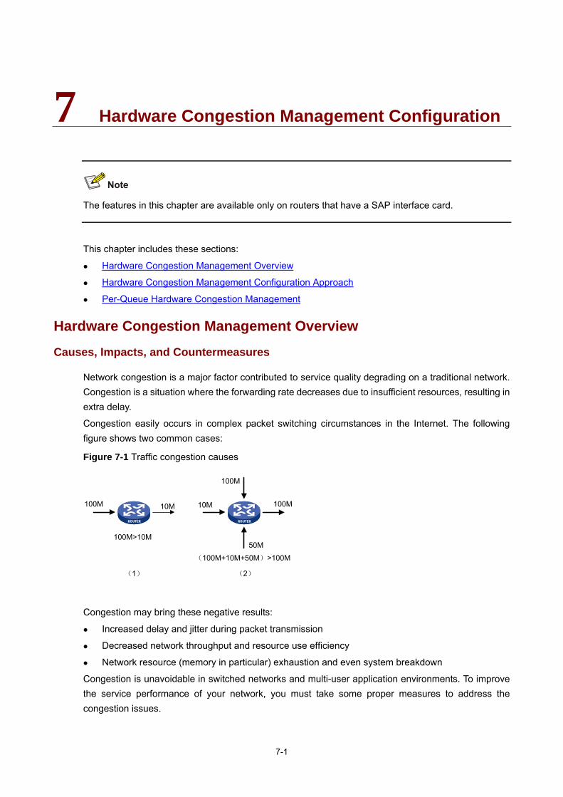
7-1
7 Hardware Congestion Management Configuration
The features in this chapter are available only on routers that have a SAP interface card.
This chapter includes these sections:
Hardware Congestion Management Overview
Hardware Congestion Management Configuration Approach
Per-Queue Hardware Congestion Management
Hardware Congestion Management Overview
Causes, Impacts, and Countermeasures
Network congestion is a major factor contributed to service quality degrading on a traditional network. Congestion is a situation where the forwarding rate decreases due to insufficient resources, resulting in extra delay.
Congestion easily occurs in complex packet switching circumstances in the Internet. The following figure shows two common cases:
Figure 7-1 Traffic congestion causes
100M>10M
(100M+10M+50M)>100M
100M
100M
100M
50M
10M10M
(1) (2)
Congestion may bring these negative results:
Increased delay and jitter during packet transmission
Decreased network throughput and resource use efficiency
Network resource (memory in particular) exhaustion and even system breakdown
Congestion is unavoidable in switched networks and multi-user application environments. To improve the service performance of your network, you must take some proper measures to address the congestion issues.

7-2
The key to congestion management is how to define a dispatching policy for resources to decide the order of forwarding packets when congestion occurs.
Congestion Management Techniques
Congestion management uses queuing and scheduling algorithms to classify and sort traffic leaving a port. Each queuing algorithm addresses a particular network traffic problem, and has a different impact on bandwidth resource assignment, delay, and jitter.
Queue scheduling processes packets by their priorities, preferentially forwarding high-priority packets. This section describes in detail Strict Priority (SP) queuing, Weighted Fair Queuing (WFQ), Weighted Round Robin (WRR) queuing, and Class-Based Queuing (CBQ).
SP queuing SP queuing is specially designed for mission-critical applications, which require preferential service to reduce the response delay when congestion occurs.
Figure 7-2 Schematic diagram for SP queuing
As shown in Figure 7-2, SP queuing classifies eight queues on a port into eight classes, numbered 7 to 0 in descending priority order.
SP queuing schedules the eight queues strictly according to the descending order of priority. It sends packets in the queue with the highest priority first. When the queue with the highest priority is empty, it sends packets in the queue with the second highest priority, and so on. Thus, you can assign mission-critical packets to the high priority queue to ensure that they are always served first and common service packets to the low priority queues and transmitted when the high priority queues are empty.
The disadvantage of SP queuing is that packets in the lower priority queues cannot be transmitted if there are packets in the higher priority queues. This may cause lower priority traffic to starve to death.
SP queuing involves:
Basic SP queuing: contains multiple queues, with each queue corresponding to a different priority. These queues are scheduled in the descending order of priority.
Multi-mode SP queuing: Extends basic SP queuing by providing multiple queue scheduling modes.
Multi-mode SP queuing operates in one of the following three modes:
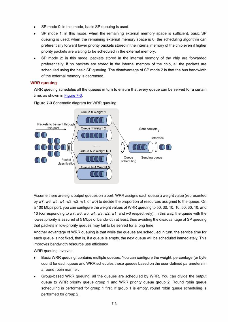
7-3
SP mode 0: in this mode, basic SP queuing is used.
SP mode 1: in this mode, when the remaining external memory space is sufficient, basic SP queuing is used; when the remaining external memory space is 0, the scheduling algorithm can preferentially forward lower priority packets stored in the internal memory of the chip even if higher priority packets are waiting to be scheduled in the external memory.
SP mode 2: in this mode, packets stored in the internal memory of the chip are forwarded preferentially; if no packets are stored in the internal memory of the chip, all the packets are scheduled using the basic SP queuing. The disadvantage of SP mode 2 is that the bus bandwidth of the external memory is decreased.
WRR queuing WRR queuing schedules all the queues in turn to ensure that every queue can be served for a certain time, as shown in Figure 7-3.
Figure 7-3 Schematic diagram for WRR queuing
Queue 0 Weight 1
……
Queue 1 Weight 2
Queue N-2 Weight N-1
Queue N-1 Weight N
Packets to be sent through this port Sent packets
Interface
Queue scheduling
Sending queuePacket
classification
Assume there are eight output queues on a port. WRR assigns each queue a weight value (represented by w7, w6, w5, w4, w3, w2, w1, or w0) to decide the proportion of resources assigned to the queue. On a 100 Mbps port, you can configure the weight values of WRR queuing to 50, 30, 10, 10, 50, 30, 10, and 10 (corresponding to w7, w6, w5, w4, w3, w2, w1, and w0 respectively). In this way, the queue with the lowest priority is assured of 5 Mbps of bandwidth at least, thus avoiding the disadvantage of SP queuing that packets in low-priority queues may fail to be served for a long time.
Another advantage of WRR queuing is that while the queues are scheduled in turn, the service time for each queue is not fixed, that is, if a queue is empty, the next queue will be scheduled immediately. This improves bandwidth resource use efficiency.
WRR queuing involves:
Basic WRR queuing: contains multiple queues. You can configure the weight, percentage (or byte count) for each queue and WRR schedules these queues based on the user-defined parameters in a round robin manner.
Group-based WRR queuing: all the queues are scheduled by WRR. You can divide the output queue to WRR priority queue group 1 and WRR priority queue group 2. Round robin queue scheduling is performed for group 1 first. If group 1 is empty, round robin queue scheduling is performed for group 2.
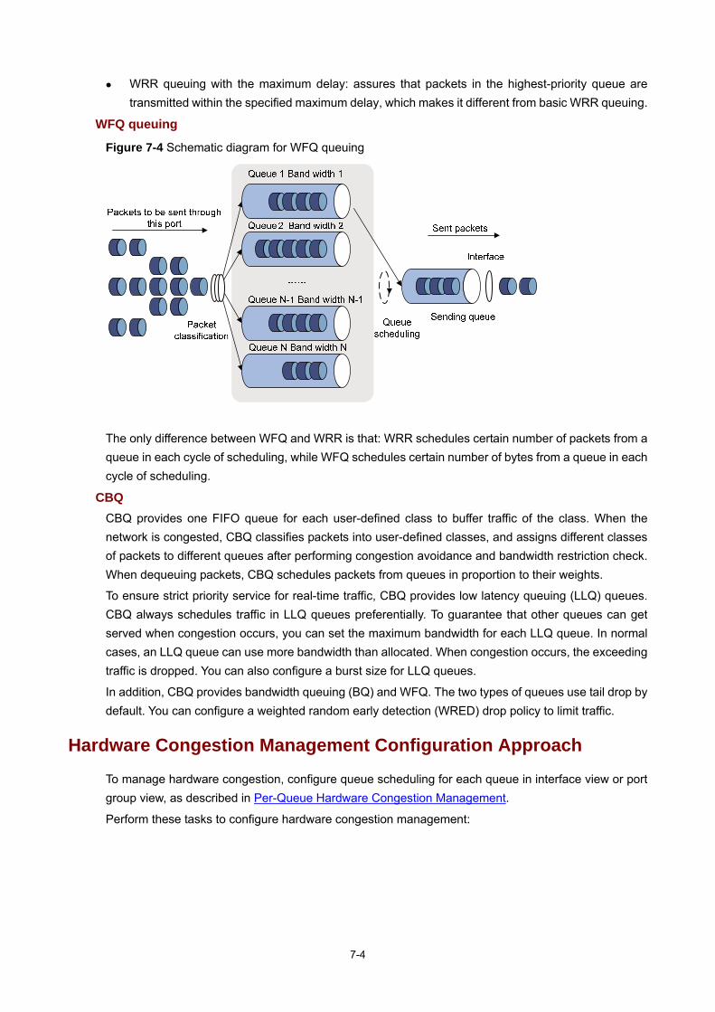
7-4
WRR queuing with the maximum delay: assures that packets in the highest-priority queue are transmitted within the specified maximum delay, which makes it different from basic WRR queuing.
WFQ queuing
Figure 7-4 Schematic diagram for WFQ queuing
The only difference between WFQ and WRR is that: WRR schedules certain number of packets from a queue in each cycle of scheduling, while WFQ schedules certain number of bytes from a queue in each cycle of scheduling.
CBQ CBQ provides one FIFO queue for each user-defined class to buffer traffic of the class. When the network is congested, CBQ classifies packets into user-defined classes, and assigns different classes of packets to different queues after performing congestion avoidance and bandwidth restriction check. When dequeuing packets, CBQ schedules packets from queues in proportion to their weights.
To ensure strict priority service for real-time traffic, CBQ provides low latency queuing (LLQ) queues. CBQ always schedules traffic in LLQ queues preferentially. To guarantee that other queues can get served when congestion occurs, you can set the maximum bandwidth for each LLQ queue. In normal cases, an LLQ queue can use more bandwidth than allocated. When congestion occurs, the exceeding traffic is dropped. You can also configure a burst size for LLQ queues.
In addition, CBQ provides bandwidth queuing (BQ) and WFQ. The two types of queues use tail drop by default. You can configure a weighted random early detection (WRED) drop policy to limit traffic.
Hardware Congestion Management Configuration Approach
To manage hardware congestion, configure queue scheduling for each queue in interface view or port group view, as described in Per-Queue Hardware Congestion Management.
Perform these tasks to configure hardware congestion management:

7-5
Task Remarks
Configuring SP Queuing Optional
Configure WRR Queuing Optional Per-Queue Hardware Congestion Management
Configuring WFQ Queuing Optional
Per-Queue Hardware Congestion Management
Configuring SP Queuing
SP queuing comprises basic SP queuing and multi-mode SP queuing. Support for SP queuing modes depends on your router model.
Configuration procedure Follow these steps to configure SP queuing:
To do… Use the command… Remarks
Enter system view system-view —
Enter interface view
interface interface-type interface-number Enter
interface view or port group view Enter port
group view port-group manual port-group-name
Use either command SP queuing is only applicable to Layer 2 interfaces. Settings in interface view take effect on the current interface. Settings in port group view take effect on all ports in the port group.
Configure SP queuing qos sp [ 0 | 1 | 2 ]
Required SP queuing is only applicable to Layer 2 interfaces. The default queuing algorithm on an interface varies with router models.
Display SP queuing configuration
display qos sp interface [ interface-type interface-number ]
Optional Available in any view
Configuration example 1) Network requirements
Configure GigabitEthernet 1/0/1 to use SP queuing.
2) Configuration procedure
# Enter system view <Sysname> system-view
# Configure GigabitEthernet 1/0/1 to use SP queuing. [Sysname]interface gigabitethernet 1/0/1
[Sysname-GigabitEthernet1/0/1] qos sp
Configure WRR Queuing
WRR queuing includes basic WRR queuing and group-based WRR queuing.

7-6
With a WRR queue configured on an interface, WRR queuing is enabled on the interface, and other queues on the interface use the default WRR scheduling value and are assigned to the default WRR priority group.
Configuration procedure 1) Configuring basic WRR queuing
Follow these steps to configure basic WRR queuing:
To do… Use the command… Remarks
Enter system view system-view —
Enter interface view
interface interface-type interface-number
Enter interface view or port group view Enter port
group view port-group manual port-group-name
Use either command Settings in interface view take effect on the current interface. Settings in port group view take effect on all ports in the port group.
Enable WRR queuing qos wrr
Required WRR queuing is only applicable to Layer 2 interfaces. The default queuing algorithm on an interface varies with router models.
Configure a basic WRR queue
qos wrr queue-id { weight | byte-count } schedule-value Required
Display WRR queuing configuration information on interface(s)
display qos wrr interface [ interface-type interface-number ]
Optional Available in any view
2) Configuring group-based WRR queuing
Follow these steps to configure group-based WRR queuing:
To do… Use the command… Remarks
Enter system view system-view —
Enter interface view
interface interface-type interface-number
Enter interface view or port group view Enter port
group view port-group manual port-group-name
Use either command Settings in interface view take effect on the current interface. Settings in port group view take effect on all ports in the port group.
Enable WRR queuing qos wrr
Required WRR queuing is only applicable to Layer 2 interfaces. The default queuing algorithm on an interface varies with router models.
Configure a group-based WRR queue
qos wrr queue-id group [ 1 | 2 ] { weight | byte-count } schedule-value Required
Configure SP+WRR queuing qos wrr queue-id group sp Required
Display WRR queuing configuration information
display qos wrr interface [ interface-type interface-number ]
Optional Available in any view

7-7
Configuration example 1) Network requirements
Enable WRR queuing on the interface.
Assign queue 0 and queue 1 to the SP group.
Assign queue 2, queue 3, and queue 4 to WRR group 1, with the weight of 1, 5, and 10 respectively.
2) Configuration procedure
# Enter system view. <Sysname> system-view
# Configure WRR queuing on Ethernet 1/1. [Sysname] interface gigabitethernet 1/0/1
[Sysname-GigabitEthernet1/0/1] qos wrr
[Sysname-GigabitEthernet1/0/1] qos wrr 0 group sp
[Sysname-GigabitEthernet1/0/1] qos wrr 1 group sp
[Sysname-GigabitEthernet1/0/1] qos wrr 2 group 1 weight 1
[Sysname-GigabitEthernet1/0/1] qos wrr 3 group 1 weight 5
[Sysname-GigabitEthernet1/0/1] qos wrr 4 group 1 weight 10
Configuring WFQ Queuing
With a WFQ queue configured, an interface has WFQ enabled. Other queues on the interface use the default WFQ scheduling value, which varies with router models.
Configuration procedure Follow these steps to configure a WFQ queue:
To do… Use the command… Remarks
Enter system view system-view —
Enter interface view
interface interface-type interface-number
Enter interface view or port group view Enter port
group view port-group manual port-group-name
Use either command Settings in interface view take effect on the current interface. Settings in port group view take effect on all ports in the port group.
Enable WFQ queuing qos wfq
Optional Whether enabling WFQ is necessary varies with router models.
Configure the minimum guaranteed bandwidth for an WFQ queue
qos bandwidth queue queue-id min bandwidth-value
Required WFQ queuing is only applicable to Layer 2 interfaces.
Specify the queue scheduling weight for an WFQ
qos wfq queue-id weight schedule-value
Required WFQ queuing is only applicable to Layer 2 interfaces.
Display WFQ queuing configuration
display qos wfq interface [ interface-type interface-number ]
Optional Available in any view
Configuration example 1) Network requirements
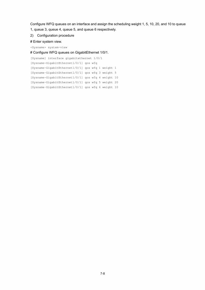
7-8
Configure WFQ queues on an interface and assign the scheduling weight 1, 5, 10, 20, and 10 to queue 1, queue 3, queue 4, queue 5, and queue 6 respectively.
2) Configuration procedure
# Enter system view. <Sysname> system-view
# Configure WFQ queues on GigabitEthernet 1/0/1. [Sysname] interface gigabitethernet 1/0/1
[Sysname-GigabitEthernet1/0/1] qos wfq
[Sysname-GigabitEthernet1/0/1] qos wfq 1 weight 1
[Sysname-GigabitEthernet1/0/1] qos wfq 3 weight 5
[Sysname-GigabitEthernet1/0/1] qos wfq 4 weight 10
[Sysname-GigabitEthernet1/0/1] qos wfq 5 weight 20
[Sysname-GigabitEthernet1/0/1] qos wfq 6 weight 10

8-1
8 Congestion Avoidance
When configuring congestion avoidance, go to these sections for information you are interested in:
Congestion Avoidance Overview
Introduction to WRED Configuration
Configuring WRED on an Interface
Displaying and Maintaining WRED
WRED Configuration Example
Congestion Avoidance Overview
Serious congestion causes great damages to the network resources, and therefore some measures must be taken to avoid such congestion. As a flow control mechanism, congestion avoidance can actively drop packets when congestion occurs or deteriorates through monitoring the utilization of network resources (such as queues or memory buffers) to prevent network overload.
Compared to point-to-point flow control, this flow control mechanism is of broader sense because it can control the load of more flows in a router. When dropping packets from a source end, it can still cooperate well with the flow control mechanism (such as TCP flow control) at the source end to better adjust the network traffic to a reasonable load status. The combination of the packet drop policy of the local router and the flow control mechanism at the source end can maximize throughput and utilization rate of the network and minimize packet loss and delay.
Traditional packet drop policy The traditional packet drop policy is tail drop. When the length of a queue reaches the maximum threshold, all the subsequent packets are dropped.
Such a policy results in global TCP synchronization. That is, if packets from multiple TCP connections are dropped, these TCP connections go into the state of congestion avoidance and slow start to reduce traffic, but traffic peak occurs later. Consequently, the network traffic jitters all the time.
RED and WRED You can use random early detection (RED) or weighted random early detection (WRED) to avoid global TCP synchronization.
Both RED and WRED avoid global TCP synchronization by randomly dropping packets. Thus, while the sending rates of some TCP sessions slow down after their packets are dropped, other TCP sessions remain at high sending rates. As there are always TCP sessions at high sending rates, link bandwidth is efficiently utilized.
The RED or WRED algorithm sets an upper threshold and lower threshold for each queue, and processes the packets in a queue as follows:
When the queue size is shorter than the lower threshold, no packet is dropped;
When the queue size reaches the upper threshold, all subsequent packets are dropped;

8-2
When the queue size is between the lower threshold and the upper threshold, the received packets are dropped at random. The longer a queue is, the higher the drop probability is. However, a maximum drop probability exists.
Different from RED, WRED determines differentiated drop policies for packets with different IP precedence values. Packets with a lower IP precedence are more likely to be dropped.
If the current queue size is compared with the upper threshold and lower threshold to determine the drop policy, bursty traffic is not fairly treated. To solve this problem, WRED compares the average queue size with the upper threshold and lower threshold to determine the drop probability.
The average queue size reflects the queue size change trend but is not sensitive to bursty queue size changes, and thus bursty traffic can be fairly treated. The average queue size is calculated using the formula: average queue size=previous average queue size×(1-2-n)+Current queue size ×2-n, where n can be configured with the qos wred weighting-constant command.
With WFQ queuing adopted, you can set the exponent for average queue size calculation, upper threshold, lower threshold, and drop probability for packets with different precedence values respectively to provide different drop policies.
With FIFO queuing, PQ, or CQ adopted, you can set the exponent for average queue size calculation, upper threshold, lower threshold, and drop probability for each queue to provide differentiated drop policies for different classes of packets.
Relation between WRED and queuing mechanism The relation between WRED and queuing mechanism is shown in the following figure:
Figure 8-1 Relationship between WRED and queuing mechanism
Through combining WRED with WFQ, the flow-based WRED can be realized. Because each flow has its own queue after classification, a flow with a smaller queue size has a lower packet drop probability, while a flow with a larger queue size has a higher packet drop probability. In this way, the benefits of the flow with a smaller queue size are protected.

8-3
Introduction to WRED Configuration
On the SR6600 routers, WRED is configured and enabled directly on interfaces.
Before configuring WRED on an interface, determine the following parameters:
The upper threshold and lower threshold: When the average queue size is smaller than the lower threshold, no packet is dropped. When the average queue size is between the lower threshold and the upper threshold, the packets are dropped at random. The longer the queue, the higher the drop probability. When the average queue size exceeds the upper threshold, subsequent packets are dropped.
The exponent used for average queue size calculation: The bigger the exponent is, the less sensitive the average queue size is to real-time queue size changes.
Denominator for drop probability calculation: The bigger the denominator, the smaller the calculated drop probability.
Configuring WRED on an Interface
Configuration Procedure
Follow these steps to configure WRED on an interface:
To do... Use the command... Remarks
Enter system view system-view —
Enter interface view interface interface-type interface-number —
Enable WRED qos wred [dscp | ip-precedence ] enable Required
Set the WRED exponent for average queue size calculation
qos wred weighting-constant exponent
Optional 9 by default
Set the drop-related parameters for the precedence
qos wred ip-precedence ip-precedence | dscp dscp-value } low-limit low-limit high-limit high-limit discard-probability discard-prob
Optional By default, the low-limit is 10, the high-limit is 30, and the discard-prob is 10.
Display WRED configuration information on the interface or all interfaces
display qos wred interface [ interface-type interface-number ]
Optional Available in any view
To configure the qos wred enable command on an interface, make sure that WFQ queuing has been applied on the interface.
Configuration Example
Network requirements Enable IP precedence-based WRED on an interface.

8-4
Set the following parameters for packets with IP precedence 3: lower threshold 20, upper threshold 40, and drop probability denominator 15.
Set the exponential factor for the average queue size calculation to 6.
Configuration procedure # Enter system view. <Sysname> system-view
# Enter interface view. [Sysname] interface gigabitethernet 1/0/1
# Enable IP precedence-based WRED. [Sysname-GigabitEthernet1/0/1] qos wred ip-precedence enable
# Set the following parameters for packets with IP precedence 3: lower threshold 20, upper threshold 40, and drop probability denominator 15. [Sysname-GigabitEthernet1/0/1] qos wred ip-precedence 3 low-limit 20 high-limit 40 discard-probability 15
# Set the exponential factor for the average queue size calculation to 6. [Sysname-GigabitEthernet1/0/1] qos wred weighting-constant 6
Displaying and Maintaining WRED
To do... Use the command... Remarks
Display WRED configuration information on the interface or all interfaces
display qos wred interface [ interface-type interface-number ]
Available in any view
WRED Configuration Example
Network requirements As shown in Figure 8-2, Server, Telephone, Host A, and Host B are connected to an IP network through Router. Server sends critical data traffic, Telephone sends voice traffic, and Host A and Host B send non-critical data traffic. On Router, because the rate of incoming interface GigabitEthernet 1/0/1 is higher than that of outgoing interface Serial 2/0/1, congestion may occur on Serial 2/0/1.
It is required that the critical traffic from Server and Telephone be transmitted preferentially when congestion occurs in the network. At the same time, certain bandwidth is guaranteed for traffic from Host A and Host B to reduce traffic delay. When congestion deteriorates, packets are dropped based on precedence.
Use WFQ in conjunction with WRED for queue scheduling and packet dropping.

8-5
Figure 8-2 Network diagram for WRED configuration
Configuration procedure # Configure ACLs to match the packets from Server, Telephone, Host A, and Host B respectively. <Router> system-view
[Router] acl number 2001
[Router-acl-basic-2001] rule 1 permit source 10.1.1.1 0
[Router-acl-basic-2001] quit
[Router] acl number 2002
[Router-acl-basic-2002] rule 2 permit source 10.1.1.2 0
[Router-acl-basic-2002] quit
[Router] acl number 2003
[Router-acl-basic-2003] rule 3 permit source 10.1.1.3 0
[Router-acl-basic-2003] quit
[Router] acl number 2004
[Router-acl-basic-2004] rule 1 permit source 10.1.1.4 0
[Router-acl-basic-2004] quit
# Mark each flow with a priority. [Router] traffic classifier class1
[Router-classifier-class1] if-match acl 2001
[Router-classifier-class1] quit
[Router] traffic classifier class2
[Router-classifier-class2] if-match acl 2002
[Router-classifier-class2] quit
[Router] traffic classifier class3
[Router-classifier-class3] if-match acl 2003
[Router-classifier-class3] quit
[Router] traffic classifier class4
[Router-classifier-class4] if-match acl 2004
[Router-classifier-class4] quit
[Router] traffic behavior behavior1
[Router-behavior-behavior1] remark ip-precedence 5
[Router-behavior-behavior1] quit
[Router]traffic behavior behavior2
[Router-behavior-behavior2] remark ip-precedence 4
[Router-behavior-behavior2] quit
[Router] traffic behavior behavior3
[Router-behavior-behavior3] remark ip-precedence 3
[Router-behavior-behavior3] quit

8-6
[Router] traffic behavior behavior4
[Router-behavior-behavior4] remark ip-precedence 2
[Router-behavior-behavior4] quit
[Router] qos policy aa
[Router-qospolicy-aa] classifier class1 behavior behavior1
[Router-qospolicy-aa] classifier class2 behavior behavior2
[Router-qospolicy-aa] classifier class3 behavior behavior3
[Router-qospolicy-aa] classifier class4 behavior behavior4
[Router-qospolicy-aa] quit
[Router] interface gigabitethernet 1/0/1
[Router-GigabitEthernet1/0/1] qos apply policy aa inbound
[Router-GigabitEthernet1/0/1] quit
# Configure WFQ to process packets both fairly and based on precedence; configure WRED to drop packets by precedence when congestion deteriorates. [Router] interface Serial 2/0/1
[Router-Serial2/0/1] qos wfq queue-length 100 queue-number 16
[Router-Serial2/0/1] qos wred enable
[Router-Serial2/0/1] qos wred ip-precedence 5 low-limit 10 high-limit 250 discard-probability 11
[Router-Serial2/0/1] qos wred ip-precedence 4 low-limit 10 high-limit 200 discard-probability 12
[Router-Serial2/0/1] qos wred ip-precedence 3 low-limit 10 high-limit 180 discard-probability 15
[Router-Serial2/0/1] qos wred ip-precedence 2 low-limit 10 high-limit 180 discard-probability 15
[Router-Serial2/0/1] quit

9-1
9 Traffic Filtering Configuration
This chapter includes these sections:
Traffic Filtering Overview
Configuring Traffic Filtering
Traffic Filtering Configuration Example
Traffic Filtering Overview
You can filter in or filter out a class of traffic by associating the class with a traffic filtering action. For example, you can filter packets sourced from a specific IP address according to network status.
Configuring Traffic Filtering
Follow these steps to configure traffic filtering:
To do… Use the command… Remarks
Enter system view system-view —
Create a class and enter class view
traffic classifier tcl-name [ operator { and | or } ] —
Configure the match criteria if-match [ not ] match-criteria —
Exit class view quit —
Create a behavior and enter behavior view traffic behavior behavior-name —
Configure the traffic filtering action filter { deny | permit }
Required deny: Drops packets. permit: Permits packets to
pass through.
Exit behavior view quit —
Create a policy and enter policy view qos policy policy-name —
Associate the class with the traffic behavior in the QoS policy
classifier tcl-name behavior behavior-name —
Exit policy view quit —
To an interface or PVC
Applying the QoS policy to an interface or PVC —
To online users Applying the QoS policy to online users —
—
—
Apply the QoS policy
To a VLAN Applying the QoS policy to a VLAN
—
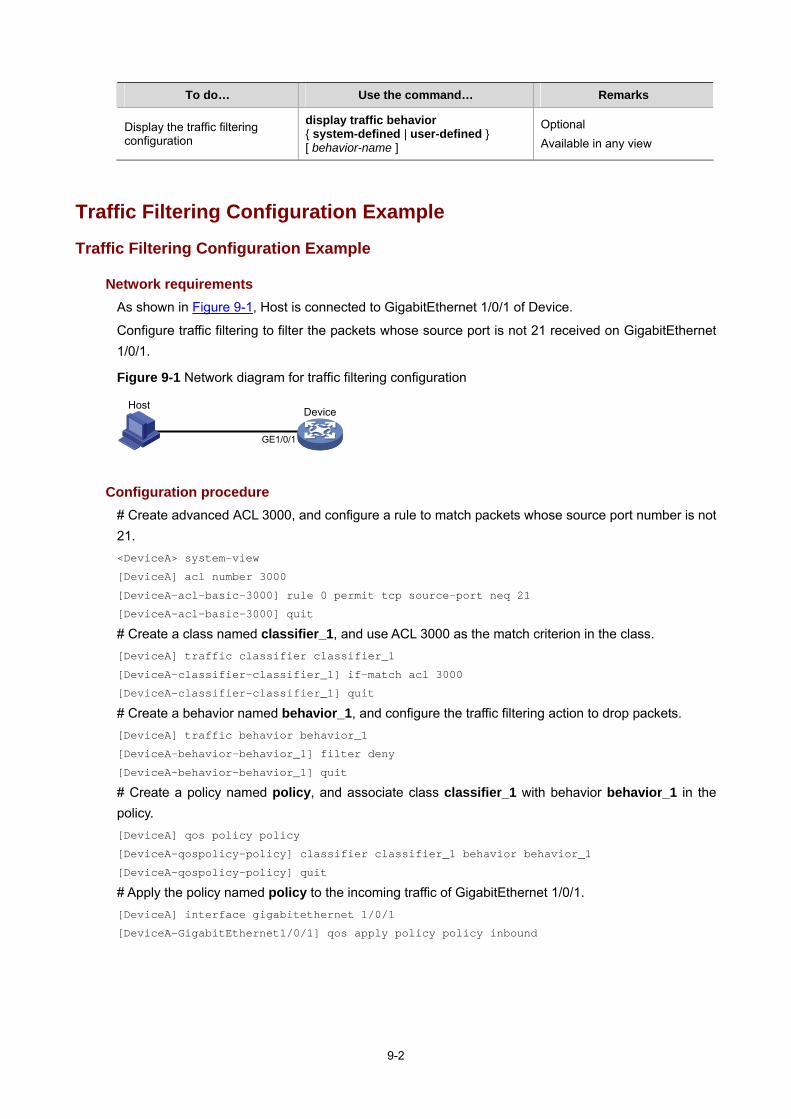
9-2
To do… Use the command… Remarks
Display the traffic filtering configuration
display traffic behavior { system-defined | user-defined } [ behavior-name ]
Optional Available in any view
Traffic Filtering Configuration Example
Traffic Filtering Configuration Example
Network requirements As shown in Figure 9-1, Host is connected to GigabitEthernet 1/0/1 of Device.
Configure traffic filtering to filter the packets whose source port is not 21 received on GigabitEthernet 1/0/1.
Figure 9-1 Network diagram for traffic filtering configuration
Device
GE1/0/1
Host
Configuration procedure # Create advanced ACL 3000, and configure a rule to match packets whose source port number is not 21. <DeviceA> system-view
[DeviceA] acl number 3000
[DeviceA-acl-basic-3000] rule 0 permit tcp source-port neq 21
[DeviceA-acl-basic-3000] quit
# Create a class named classifier_1, and use ACL 3000 as the match criterion in the class. [DeviceA] traffic classifier classifier_1
[DeviceA-classifier-classifier_1] if-match acl 3000
[DeviceA-classifier-classifier_1] quit
# Create a behavior named behavior_1, and configure the traffic filtering action to drop packets. [DeviceA] traffic behavior behavior_1
[DeviceA-behavior-behavior_1] filter deny
[DeviceA-behavior-behavior_1] quit
# Create a policy named policy, and associate class classifier_1 with behavior behavior_1 in the policy. [DeviceA] qos policy policy
[DeviceA-qospolicy-policy] classifier classifier_1 behavior behavior_1
[DeviceA-qospolicy-policy] quit
# Apply the policy named policy to the incoming traffic of GigabitEthernet 1/0/1. [DeviceA] interface gigabitethernet 1/0/1
[DeviceA-GigabitEthernet1/0/1] qos apply policy policy inbound

10-1
10 Priority Marking Configuration
This chapter includes these sections:
Priority Marking Overview
Configuring Priority Marking
Priority Marking Configuration Example
Priority Marking Overview
Priority marking sets the priority fields or flag bits of packets to modify the priority of traffic. For example, you can use priority marking to set IP precedence or DSCP for a class of IP traffic to change its transmission priority in the network.
To configure priority marking, you can associate a class with a behavior configured with the priority marking action to set the priority fields or flag bits of the class of packets.
Configuring Priority Marking
Follow these steps to configure priority marking:
To do… Use the command… Remarks
Enter system view system-view —
Create a class and enter class view
traffic classifier tcl-name [ operator { and | or } ] —
Configure the match criteria if-match [ not ] match-criteria —
Exit class view quit —
Create a behavior and enter behavior view traffic behavior behavior-name —
Set the DSCP value for packets remark dscp dscp-value Optional
Set the 802.1p priority for packets or configure the inner-to-outer tag priority copying function
remark dot1p 8021p Optional
Set the drop precedence for packets
remark drop-precedence drop-precedence-value
Optional Applicable to only the outbound direction
Set the IP precedence for packets
remark ip-precedence ip-precedence-value Optional
Set the local precedence for packets
remark local-precedence local-precedence Optional
Set the QoS-local-ID for packets remark qos-local-id local-id-value Optional
Exit behavior view quit —

10-2
To do… Use the command… Remarks
Create a policy and enter policy view qos policy policy-name —
Associate the class with the traffic behavior in the QoS policy
classifier tcl-name behavior behavior-name —
Exit policy view quit —
To an interface or PVC
Applying the QoS policy to an interface or PVC —
To online users Applying the QoS policy to online users —
—
—
Apply the QoS policy
To a VLAN Applying the QoS policy to a VLAN
—
Display the priority marking configuration
display traffic behavior { system-defined | user-defined } [ behavior-name ]
Optional Available in any view
Priority Marking Configuration Example
Priority Marking Configuration Example
Network requirements As shown in Figure 10-1, the enterprise network of a company interconnects hosts with servers through Device. The network is described as follows:
Host A and Host B are connected to GigabitEthernet 1/0/1 of Device.
The data server, mail server, and file server are connected to GigabitEthernet 1/0/2 of Device.
Configure priority marking on Device to satisfy the following requirements:
Traffic source Destination Processing priority
Host A, B Data server High
Host A, B Mail server Medium
Host A, B File server Low

10-3
Figure 10-1 Network diagram for priority marking configuration
Internet
Host A
Host BDevice
Data server192.168.0.1/24
Mail server192.168.0.2/24
File server192.168.0.3/24
GE1/0/1 GE1/0/2
Configuration procedure # Create advanced ACL 3000, and configure a rule to match packets with destination IP address 192.168.0.1. <Device> system-view
[Device] acl number 3000
[Device-acl-adv-3000] rule permit ip destination 192.168.0.1 0
[Device-acl-adv-3000] quit
# Create advanced ACL 3001, and configure a rule to match packets with destination IP address 192.168.0.2. [Device] acl number 3001
[Device-acl-adv-3001] rule permit ip destination 192.168.0.2 0
[Device-acl-adv-3001] quit
# Create advanced ACL 3002, and configure a rule to match packets with destination IP address 192.168.0.3. [Device] acl number 3002
[Device-acl-adv-3002] rule permit ip destination 192.168.0.3 0
[Device-acl-adv-3002] quit
# Create a class named classifier_dbserver, and use ACL 3000 as the match criterion in the class. [Device] traffic classifier classifier_dbserver
[Device-classifier-classifier_dbserver] if-match acl 3000
[Device-classifier-classifier_dbserver] quit
# Create a class named classifier_mserver, and use ACL 3001 as the match criterion in the class. [Device] traffic classifier classifier_mserver
[Device-classifier-classifier_mserver] if-match acl 3001
[Device-classifier-classifier_mserver] quit
# Create a class named classifier_fserver, and use ACL 3002 as the match criterion in the class. [Device] traffic classifier classifier_fserver
[Device-classifier-classifier_fserver] if-match acl 3002
[Device-classifier-classifier_fserver] quit
# Create a behavior named behavior_dbserver, and configure the action of setting the DSCP value to 32. [Device] traffic behavior behavior_dbserver
[Device-behavior-behavior_dbserver] remark dscp 32
[Device-behavior-behavior_dbserver] quit

10-4
# Create a behavior named behavior_mserver, and configure the action of setting the DSCP value to 24. [Device] traffic behavior behavior_mserver
[Device-behavior-behavior_mserver] remark dscp 24
[Device-behavior-behavior_mserver] quit
# Create a behavior named behavior_fserver, and configure the action of setting the DSCP value to 16. [Device] traffic behavior behavior_fserver
[Device-behavior-behavior_fserver] remark dscp 16
[Device-behavior-behavior_fserver] quit
# Create a policy named policy_server, and associate classes with behaviors in the policy. [Device] qos policy policy_server
[Device-qospolicy-policy_server] classifier classifier_dbserver behavior behavior_dbserver
[Device-qospolicy-policy_server] classifier classifier_mserver behavior behavior_mserver
[Device-qospolicy-policy_server] classifier classifier_fserver behavior behavior_fserver
[Device-qospolicy-policy_server] quit
# Apply the policy named policy_server to the incoming traffic of GigabitEthernet 1/0/1. [Device] interface gigabitethernet 1/0/1
[Device-GigabitEthernet1/0/1] qos apply policy policy_server inbound
[Device-GigabitEthernet1/0/1] quit

11-1
11 Traffic Redirecting Configuration
The features in this chapter are available only on routers that have a SAP interface card.
This chapter includes these sections:
Traffic Redirecting Overview
Configuring Traffic Redirecting
Traffic Redirecting Configuration Examples
Traffic Redirecting Overview
Traffic redirecting is the action of redirecting the packets matching the specific match criteria to a certain location for processing.
Currently, the following redirect actions are supported:
Redirecting traffic to the CPU: redirects packets which require processing by CPU to the CPU.
Redirecting traffic to an interface: redirects packets which require processing by an interface to the interface. Note that this action applies to only Layer 2 packets, and the target interface should be a Layer 2 interface.
Configuring Traffic Redirecting
Follow these steps to configure traffic redirecting:
To do… Use the command… Remarks
Enter system view system-view —
Create a class and enter class view
traffic classifier tcl-name [ operator { and | or } ] —
Configure the match criteria if-match [ not ] match-criteria —
Exit class view quit —
Create a behavior and enter behavior view traffic behavior behavior-name Required
Configure a traffic redirecting action
redirect { cpu | interface interface-type interface-number } Optional
Exit behavior view quit —
Create a policy and enter policy view qos policy policy-name —

11-2
To do… Use the command… Remarks
Associate the class with the traffic behavior in the QoS policy
classifier tcl-name behavior behavior-name —
Exit policy view quit —
To an interface or PVC
Applying the QoS policy to an interface or PVC — Apply the
QoS policy To a VLAN Applying the QoS policy to a VLAN —
Redirecting traffic to the CPU and redirecting traffic to an interface are mutually exclusive with each other in the same traffic behavior.
You can use the display traffic behavior command to view the traffic redirecting configuration.
Traffic Redirecting Configuration Examples
Redirecting Traffic to an Interface
Network requirements As shown in Figure 11-1, configure redirecting traffic to an interface to satisfy the following requirements:
Packets with source IP address 2.1.1.1 received on GigabitEthernet 1/0/1 of Device A are forwarded out interface GigabitEthernet 1/0/2.
Packets with source IP address 2.1.1.2 received on GigabitEthernet 1/0/1 of Device A are forwarded out interface GigabitEthernet 1/0/3.
Other packets received on GigabitEthernet 1/0/1 of Device A are forwarded out interface GigabitEthernet 1/0/4.
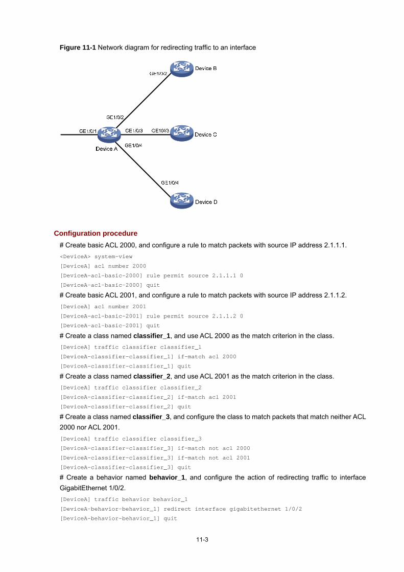
11-3
Figure 11-1 Network diagram for redirecting traffic to an interface
Configuration procedure # Create basic ACL 2000, and configure a rule to match packets with source IP address 2.1.1.1. <DeviceA> system-view
[DeviceA] acl number 2000
[DeviceA-acl-basic-2000] rule permit source 2.1.1.1 0
[DeviceA-acl-basic-2000] quit
# Create basic ACL 2001, and configure a rule to match packets with source IP address 2.1.1.2. [DeviceA] acl number 2001
[DeviceA-acl-basic-2001] rule permit source 2.1.1.2 0
[DeviceA-acl-basic-2001] quit
# Create a class named classifier_1, and use ACL 2000 as the match criterion in the class. [DeviceA] traffic classifier classifier_1
[DeviceA-classifier-classifier_1] if-match acl 2000
[DeviceA-classifier-classifier_1] quit
# Create a class named classifier_2, and use ACL 2001 as the match criterion in the class. [DeviceA] traffic classifier classifier_2
[DeviceA-classifier-classifier_2] if-match acl 2001
[DeviceA-classifier-classifier_2] quit
# Create a class named classifier_3, and configure the class to match packets that match neither ACL 2000 nor ACL 2001. [DeviceA] traffic classifier classifier_3
[DeviceA-classifier-classifier_3] if-match not acl 2000
[DeviceA-classifier-classifier_3] if-match not acl 2001
[DeviceA-classifier-classifier_3] quit
# Create a behavior named behavior_1, and configure the action of redirecting traffic to interface GigabitEthernet 1/0/2. [DeviceA] traffic behavior behavior_1
[DeviceA-behavior-behavior_1] redirect interface gigabitethernet 1/0/2
[DeviceA-behavior-behavior_1] quit

11-4
# Create a behavior named behavior_2, and configure the action of redirecting traffic to interface GigabitEthernet 1/0/3. [DeviceA] traffic behavior behavior_2
[DeviceA-behavior-behavior_2] redirect interface gigabitethernet 1/0/3
[DeviceA-behavior-behavior_2] quit
# Create a behavior named behavior_3, and configure the action of redirecting traffic to interface GigabitEthernet 1/0/4. [DeviceA] traffic behavior behavior_3
[DeviceA-behavior-behavior_3] redirect interface gigabitethernet 1/0/4
[DeviceA-behavior-behavior_3] quit
# Create a policy named policy, associate class classifier_1 with behavior behavior_1, classifier_2 with behavior_2, and classifier_3 with behavior_3 in the policy. [DeviceA] qos policy policy
[DeviceA-qospolicy-policy] classifier classifier_1 behavior behavior_1
[DeviceA-qospolicy-policy] classifier classifier_2 behavior behavior_2
[DeviceA-qospolicy-policy] classifier classifier_3 behavior behavior_3
[DeviceA-qospolicy-policy] quit
# Apply the policy named policy to the incoming traffic of GigabitEthernet 1/0/1. [DeviceA] interface gigabitethernet 1/0/1
[DeviceA-GigabitEthernet1/0/1] qos apply policy policy inbound

12-1
12 EACL Configuration
The features in this chapter are available only on routers that have a SAP interface card.
This chapter includes these sections:
EACL Overview
EACL Configuration Task List
Configuring BT Traffic Limiting
EACL Configuration Example
Troubleshooting EACL
EACL Overview
Enhanced ACL (EACL) refers to redirecting an ACL to a service card. Currently, routers support only BT traffic limiting.
EACL Configuration Task List
Complete the following task to configure EACL:
Task Remarks
Configuring BT Traffic Limiting Optional
Configuring BT Traffic Limiting
BitTorrent (BT) is a kind of shared software used for file downloading. It features the more users, the faster the downloading. Though BT reduces the load of the download server, it greatly increases the amount of downloaded data, occupying a large amount of network bandwidth and serious affecting other network applications. Thus, controlling BT traffic is required.
QoS identifies BT traffic by the BitTorrent protocol field, and then limits BT traffic.
Follow these steps to configure BT traffic limiting:
To do… Use the command… Remarks
Enter system view system-view —
Enter advanced ACL view acl number acl-number [ match-order { config | auto } ] —

12-2
To do… Use the command… Remarks
Define an ACL rule rule [ rule-id ] permit tcp [ rule-string ] Required
Exit ACL view quit —
Enter class view traffic classifier tcl-name —
Configure an ACL based match criterion if-match acl acl-number Required
Match BT packets if-match protocol bittorrent Required
Exit class view quit —
Enter traffic behavior view traffic behavior behavior-name —
Configure a CAR action car cir committed-information-rate cbs committed-burst-size ebs excess-burst-size [ red action ]
Required The parameters set with the command must satisfy the following requirements: cir x 128 ≤ cbs ≤ ebs ≤ cir x 128 x 90
Exit traffic behavior view quit —
Create a policy and enter policy view qos policy policy-name —
Associate the traffic behavior with the class in the policy
classifier tcl-name behavior behavior-name Required
Exit policy view quit —
Enter EACL service subinterface view interface eacl interface-number —
Apply the QoS policy to the outgoing traffic of the subinterface
qos apply policy policy-name outbound
Required A QoS policy can be applied only to the outgoing traffic of an EACL service subinterface.
Configure interface binding qos binding interface interface-type interface-number Required
After configuring BT traffic limiting, configure a traffic redirecting action to redirect packets on the specified interface to a service card. See Traffic Redirecting Configuration for more information on traffic redirecting configuration.
EACL Configuration Example
BT Traffic Limiting Configuration Example
Network requirements As shown in Figure 12-1, configure an ACL to limit BT traffic rate from Host B to Host A to 100 kbps.

12-3
Figure 12-1 Network diagram for BT traffic limiting
GE1/0/3
GE1/0/2GE1/0/1VLAN 40 VLAN 3
Host A Host B2.0.0.1/81.0.0.1/8
Router
Configuration procedure # Enter system view. <Switch> system-view
# Configure a QoS policy for BT traffic limiting and apply it to the service card. [Router] acl number 3000
[Router-acl-adv-3000] rule permit tcp
[Router-acl-adv-3000] quit
[Router] traffic classifier 1
[Router-classifier-1] if-match acl 3000
[Router-classifier-1] if-match protocol bittorrent
[Router-classifier-1] quit
[Router] traffic behavior 1
[Router-behavior-1] car cir 100 cbs 150000 ebs 200000
[Router-behavior-1] quit
[Router] qos policy 1
[Router-qospolicy-1] classifier 1 behavior 1
[Router-qospolicy-1] quit
[Router] interface eacl 8/0/1.1
[Router-EACL8/0/1.1] qos apply policy 1 outbound
[Router-EACL8/0/1.1] qos binding interface vlan-interface 3
[Router-EACL8/0/1.1] quit
# Configure a traffic redirecting policy and apply the policy to both the inbound and outbound directions of VLAN 3. [Router] acl number 2000
[Router-acl-basic-2000] rule permit
[Router-acl-basic-2000] quit
[Router] traffic classifier 2
[Router-classifier-2] if-match acl 2000
[Router-classifier-2] quit
[Router] traffic behavior 2
[Router-behavior-2] redirect interface eacl 8/0/1
[Router-behavior-2] quit
[Router] qos policy 2
[Router-policy-2] classifier 2 behavior 2
[Router-qospolicy-2] quit
[Router] qos vlan-policy 2 vlan 3 inbound
[Router] qos vlan-policy 2 vlan 3 outbound

12-4
Troubleshooting EACL
Symptom The EACL feature does not work on the router.
Analysis Appropriate rules should be configured.
A traffic behavior should be specified for the traffic class in the policy.
The packets on the designated port should be redirected to the service card.
Solution Verify that the appropriate match criteria are configured with the if-match command.
Verify that a traffic behavior is specified for the traffic class with the classifier tcl-name behavior behavior-name command.
Verify that the QoS policy is applied to the designated interface and the EACL service subinterface is bound to the layer-3 interface with the qos apply policy command and the qos binding interface command.

13-1
13 DAR Configuration
This chapter includes these sections:
DAR Overview
Configuring DAR for P2P Traffic Identification
Displaying and Maintaining DAR
DAR Configuration Examples
DAR Overview
The Deeper Application Recognition (DAR) feature identifies packets of dynamic protocols like BitTorrent, HTTP, FTP, and RTP by examining Layer 4 to Layer 7 content other than the IP header. The feature helps service providers and businesses limit aggressive bandwidth use by applications like BitTorrent to ensure fairness and network performance.
BitTorrent is a peer to peer (P2P) file sharing communications protocol, which enables personal computers to directly exchange data or services. P2P has been widely used for content (such as audio and video) file sharing, representing a large amount of bandwidth on the Internet.
DAR can limit, block, or manipulate identified application traffic depending on your configuration.
The DAR feature is applicable to IP packets. It is available only on the Ethernet interfaces on the SR6602.
Configuring DAR for P2P Traffic Identification
DAR uses a .mtd P2P signature file for P2P traffic identification. It compares the content of every incoming packet with the signature file. If a match is found, DAR processes the packet as a P2P packet.
Loading the P2P Signature File
To identify P2P traffic, you must first load the P2P signature file. Ensure that the signature file is placed in the root directory. The system can load a signature file only from the root directory.
Follow these steps to load the P2P signature file:
To do… Use the command… Remarks
Enter system view system-view —
Load the P2P signature file dar p2p signature-file filename Required No P2P signature file is loaded by default.

13-2
Configuring a P2P Protocol Group
You can configure a P2P protocol group to include multiple P2P protocols. You can reference this P2P protocol group in a traffic class to perform QoS actions on them.
Follow these steps to configure a P2P protocol group:
To do… Use the command… Remarks
Enter system view system-view —
Create a P2P protocol group and enter protocol group view dar protocol-group group-id
Required By default, no protocol group exists in the system.
Assign a protocol to the protocol group protocol protocol-name
Required By default, a protocol group contains no protocol.
Enabling P2P Traffic Recognition
P2P traffic recognition is system resource demanding. It is disabled by default to avoid impacts on other modules.
Follow these steps to enable P2P traffic recognition:
To do… Use the command… Remarks
Enter system view system-view —
Enter Layer-3 Ethernet interface view
interface interface-type interface-number —
Enable P2P traffic recognition dar enable Required Disabled by default.
Configuring Protocol Match Criteria
To apply QoS policies to data streams, to set packet priority or allocate bandwidth for example, use DAR to classify the data streams first.
Follow these steps to configure protocol match criteria:
To do… Use the command… Remarks
Enter system view system-view —
Enter class view traffic classifier tcl-name [ operator { and | or } ] Required
Configure the match criterion for a protocol group
if-match [ not ] protocol-group protocol-group-id
Optional Not configured by default.
Configuring DAR Packet Accounting
With the packet accounting function of DAR, you can monitor the number of packets and the amount of data traffic on an interface and apply a correct policy to the traffic.

13-3
Follow these steps to configure DAR packets accounting:
To do… Use the command… Remarks
Enter system view system-view —
Enter interface view interface interface-type interface-number —
Enable DAR packet accounting dar protocol-statistic [ flow-interval time ]
Required Disabled by default
Displaying and Maintaining DAR
To do… Use the command… Remarks
Display DAR protocol packet statistics
display dar protocol-statistic [ p2p | protocol protocol-name | top top-number | all ] [ interface interface-type interface-number ] [ direction { in | out } ]
Available in any view
Clear DAR protocol packet statistics
reset dar protocol-statistic p2p [ interface interface-type interface-number ] reset dar protocol-statistic interface interface-type interface-number p2p
Available in user view
DAR Configuration Examples
P2P Downloading Traffic Blocking Configuration Example
Network requirements As shown in Figure 13-1, a router provides access to the Internet for PCs attached to it.
Configure the router to prevent BT or eMule/eDonkey clients on the PCs from downloading files from the Internet.
Figure 13-1 Network diagram for DAR configuration
Configuration procedure # Load the P2P signature file meta.mtd. <Router> system-view
[Router] dar p2p signature-file meta.mtd
# Configure protocol group 1. [Router] dar protocol-group 1
[Router-protocol-group-1] protocol bittorrent
[Router-protocol-group-1] protocol eMule/eDonkey
[Router-protocol-group-1] quit
# Create a class and reference protocol group 1 in it. [Router] traffic classifier p2p

13-4
[Router-classifier-p2p] if-match protocol-group 1
[Router-classifier-p2p] quit
# Configure a packet filtering behavior. [Router] traffic behavior deny
[Router-behavior-deny] filter deny
[Router-behavior-deny] quit
# Create a QoS policy and associate the traffic behavior with the class in the policy. [Router] qos policy p2p
[Router-qospolicy-p2p] classifier p2p behavior deny
[Router-qospolicy-p2p] quit
# Enable P2P traffic recognition on Ethernet 1/1 and apply the QoS policy to the incoming traffic of Ethernet 1/1. [Router] interface ethernet 1/1
[Router-Ethernet1/1] dar enable
[Router-Ethernet1/1] qos apply policy p2p inbound
Run the BT client and the eMule/eDonkey client on a connected PC and start to download files.
Check the interfaces of the clients, and you can see they cannot download files.

14-1
14 Class-Based Accounting Configuration
This chapter includes these sections:
Class-Based Accounting Overview
Configuring Class-Based Accounting
Displaying and Maintaining Class-Based Traffic Accounting
Class-Based Accounting Configuration Example
Class-Based Accounting Overview
Class-based accounting collects statistics on a per-traffic class basis. For example, you can define the action to collect statistics for traffic sourced from a certain IP address. By analyzing the statistics, you can determine whether there are anomalies and what action to take.
Configuring Class-Based Accounting
Follow these steps to configure class-based accounting:
To do… Use the command… Remarks
Enter system view system-view —
Create a class and enter class view
traffic classifier tcl-name [ operator { and | or } ] —
Configure the match criteria if-match [ not ] match-criteria —
Exit class view quit —
Create a behavior and enter behavior view traffic behavior behavior-name Required
Configure the accounting action accounting Optional The SR6600 routers support counting traffic in packets.
Exit behavior view quit —
Create a policy and enter policy view qos policy policy-name —
Associate the class with the traffic behavior in the QoS policy
classifier tcl-name behavior behavior-name —
Exit policy view quit —
To an interface or PVC
Applying the QoS policy to an interface or PVC —
—
—
Apply the QoS policy To a VLAN Applying the QoS policy to a VLAN
—

14-2
Displaying and Maintaining Class-Based Traffic Accounting
To verify the class-based accounting configuration, use the display qos policy command in any view to display the traffic statistics collected after the configuration is complete.
Class-Based Accounting Configuration Example
Class-Based Accounting Configuration Example
Network requirements As shown in Figure 14-1, Host is connected to GigabitEthernet 1/0/1 of Device.
Configure class-based accounting to collect statistics for traffic sourced from 1.1.1.1/24 and received on GigabitEthernet 1/0/1.
Figure 14-1 Network diagram for traffic accounting configuration
Configuration procedure # Create basic ACL 2000, and configure a rule to match packets with source IP address 1.1.1.1. <DeviceA> system-view
[DeviceA] acl number 2000
[DeviceA-acl-basic-2000] rule permit source 1.1.1.1 0
[DeviceA-acl-basic-2000] quit
# Create a class named classifier_1, and use ACL 2000 as the match criterion in the class. [DeviceA] traffic classifier classifier_1
[DeviceA-classifier-classifier_1] if-match acl 2000
[DeviceA-classifier-classifier_1] quit
# Create a behavior named behavior_1, and configure the traffic accounting action. [DeviceA] traffic behavior behavior_1
[DeviceA-behavior-behavior_1] accounting
[DeviceA-behavior-behavior_1] quit
# Create a policy named policy, and associate class classifier_1 with behavior behavior_1 in the policy. [DeviceA] qos policy policy
[DeviceA-qospolicy-policy] classifier classifier_1 behavior behavior_1
[DeviceA-qospolicy-policy] quit
# Apply the policy named policy to the incoming traffic of GigabitEthernet 1/0/1. [DeviceA] interface gigabitethernet 1/0/1
[DeviceA-GigabitEthernet1/0/1] qos apply policy policy inbound
[DeviceA-GigabitEthernet1/0/1] quit
# Display traffic statistics to verify the configuration. [DeviceA] display qos policy interface gigabitethernet 1/0/1
Interface: GigabitEthernet1/0/1

14-3
Direction: Inbound
Policy: policy
Classifier: classifier_1
Operator: AND
Rule(s) : If-match acl 2000
Behavior: behavior_1
Accounting Enable:
28529 (Packets)

15-1
15 Appendix
This chapter includes these sections:
Appendix A Acronym
Appendix B Default Priority Mapping Tables
Appendix C Introduction to Packet Precedences
Appendix A Acronym
Table 15-1 Appendix A Acronym
Acronym Full spelling
AF Assured Forwarding
BE Best Effort
CAR Committed Access Rate
CBS Committed Burst Size
CBWFQ Class Based Weighted Fair Queuing
CE Customer Edge
CIR Committed Information Rate
CQ Custom Queuing
DAR Deeper Application Recognition
DiffServ Differentiated Service
DSCP Differentiated Services Codepoint
EACL Enhanced ACL
EBS Excess Burst Size
EF Expedited Forwarding
FEC Forwarding Equivalence Class
FIFO First in First out
GTS Generic Traffic Shaping
IntServ Integrated Service
ISP Internet Service Provider
LFI Link Fragmentation & Interleaving
LLQ Low Latency Queuing
LR Line Rate
LSP Label Switched Path
MPLS Multiprotocol Label Switching
PE Provider Edge

15-2
Acronym Full spelling
PIR Peak Information Rate
PQ Priority Queuing
QoS Quality of Service
RED Random Early Detection
RSVP Resource Reservation Protocol
RTP Real Time Protocol
SLA Service Level Agreement
TE Traffic Engineering
ToS Type of Service
TP Traffic Policing
TS Traffic Shaping
VoIP Voice over IP
VPN Virtual Private Network
WFQ Weighted Fair Queuing
WRED Weighted Random Early Detection
Appendix B Default Priority Mapping Tables
For the default dot1p-exp, dscp-dscp, and exp-dot1p priority mapping tables, an input value yields a target value that is equal to it.
Table 15-2 The default dot1p-lp and dot1p-dp priority mapping tables
Input priority value dot1p-lp mapping dot1p-dp mapping
802.1p priority (dot1p) Local precedence
(lp) Drop precedence (dp)
0 2 0
1 0 0
2 1 0
3 3 0
4 4 0
5 5 0
6 6 0

15-3
Input priority value dot1p-lp mapping dot1p-dp mapping
7 7 0
Table 15-3 The default dscp-dp and dscp-dot1p priority mapping tables
Input priority value dscp-dp mapping dscp-dot1p mapping
DSCP Drop precedence (dp) 802.1p priority (dot1p)
0 to 7 0 0
8 to 15 0 1
16 to 23 0 2
24 to 31 0 3
32 to 39 0 4
40 to 47 0 5
48 to 55 0 6
56 to 63 0 7
Table 15-4 The default exp-dp priority mapping table
Input priority value exp-dp mapping
EXP value Drop precedence (dp)
0 0
1 0
2 0
3 0
4 0
5 0
6 0
7 0

15-4
Appendix C Introduction to Packet Precedences
IP Precedence and DSCP Values
Figure 15-1 ToS and DS fields
As shown in Figure 15-1, the ToS field in the IP header contains eight bits. The first three bits (0 to 2) represent IP precedence from 0 to 7. According to RFC 2474, the ToS field is redefined as the differentiated services (DS) field, where a DSCP value is represented by the first six bits (0 to 5) and is in the range 0 to 63. The remaining two bits (6 and 7) are reserved.
Table 15-5 Description on IP precedence
IP precedence (decimal) IP precedence (binary) Description
0 000 Routine
1 001 priority
2 010 immediate
3 011 flash
4 100 flash-override
5 101 critical
6 110 internet
7 111 network
Table 15-6 Description on DSCP values
DSCP value (decimal) DSCP value (binary) Description
46 101110 ef
10 001010 af11
12 001100 af12
14 001110 af13
18 010010 af21
20 010100 af22
22 010110 af23
26 011010 af31
28 011100 af32

15-5
DSCP value (decimal) DSCP value (binary) Description
30 011110 af33
34 100010 af41
36 100100 af42
38 100110 af43
8 001000 cs1
16 010000 cs2
24 011000 cs3
32 100000 cs4
40 101000 cs5
48 110000 cs6
56 111000 cs7
0 000000 be (default)
802.1p Priority
802.1p priority lies in the Layer 2 header and applies to occasions where Layer 3 header analysis is not needed and QoS must be assured at Layer 2.
Figure 15-2 An Ethernet frame with an 802.1Q tag header
As shown in Figure 15-2, the 4-byte 802.1Q tag header consists of the tag protocol identifier (TPID, two bytes in length), whose value is 0x8100, and the tag control information (TCI, two bytes in length). Figure 15-3 presents the format of the 802.1Q tag header. The Priority field in the 802.1Q tag header is called the 802.1p priority, because its use is defined in IEEE 802.1p. Table 15-7 presents the values for 802.1p priority.
Figure 15-3 802.1Q tag header
1 0 0 0 0 0 0 1 0 0 0 0 0 0 0 Priority VLAN ID
TPID (Tag protocol identifier) TCI (Tag control information)
Byte 1 Byte 2
0
Byte 3 Byte 4
CFI
7 5 4 3 2 1 0 7 5 4 3 2 1 06 6 7 5 4 3 2 1 0 7 5 4 3 2 1 06 6

15-6
Table 15-7 Description on 802.1p priority
802.1p priority (decimal) 802.1p priority (binary) Description
0 000 best-effort
1 001 background
2 010 spare
3 011 excellent-effort
4 100 controlled-load
5 101 video
6 110 voice
7 111 network-management
802.11e Priority
To provide QoS services on WLAN, the 802.11e standard was developed. IEEE 802.11e is a MAC-layer enhancement to IEEE 802.11. IEEE 802.11e adds a 2-byte QoS Control field to the 802.11e MAC frame header. Three bits of the QoS control field represents the 802.11e priority, which ranges from 0 to 7.
Figure 15-4 802.11e frame structure
EXP Values
The EXP field is in MPLS labels for MPLS QoS purposes.
Figure 15-5 MPLS label structure
As shown in Figure 15-5, the EXP field is 3 bits long and ranges from 0 to 7.

16-1
16 MPLS QoS Configuration
This chapter includes these sections:
MPLS QoS Overview
Configuring MPLS QoS
MPLS QoS Configuration Example
MPLS QoS Overview
The MPLS-related knowledge is necessary for understanding MPLS QoS. For more information about MPLS, see MPLS Basic in the MPLS Configuration Guide.
For more information about EXP precedence, traffic policing, priority marking, and congestion management, see QoS in the ACL and QoS Configuration Guide.
In the area of QoS, in order to provide the support for differentiated services (DiffServ) as IP does, MPLS uses three bits analogous to IP precedence, called EXP bits to carry class-of-service information. With the EXP bits, MPLS QoS is achieved to identify different traffic flows and implement differentiated services, thus guaranteeing low delay and low packet loss ratio for voice and video traffic.
MPLS QoS provides the following functions:
Classifies traffic on the PE to apply differentiated QoS strategies for different traffic classes. For example, MPLS QoS can organize packets with EXP value 1 into a class and packets with EXP value 2 into another class, and then perform traffic policing and priority marking for each class of packets.
Maps the IP precedence to the EXP field of the label when a PE labels a packet. In this way, the class information carried in the IP header is carried in the label.
Performs differentiated dispatching (such as PQ, WFQ, or CBQ) between a P device and a PE according to the EXP field to provide differentiated QoS for labeled traffic on an LSP.

16-2
The EXP field in an MPLS label is processed as follows:
Any QoS-capable router can reset the EXP field of the outer label.
During label encapsulation, the ToS field of the IP packet is directly changed into the EXP field of the MPLS label.
The EXP field remains unchanged when label swapping is performed.
During a label push operation, the EXP field of the newly pushed outer label inherits the EXP field of the inner label.
After a label pop operation, if the packet is still an MPLS packet, the EXP field of the popped label is not copied to the inner label; if the packet is an IP packet, the EXP field of the popped label is not copied to the ToS field of the IP packet.
Configuring MPLS QoS
Currently, MPLS QoS supports CAR, priority marking, and congestion management.
Configuring MPLS CAR
By configuring CAR for traffic entering an MPLS network, you can limit the transmission rate to avoid network congestion, and in addition, mark priority for the traffic.
Configuration prerequisites MPLS related configurations are completed.
Configuration procedure Follow these steps to configure MPLS CAR:
To do… Use the command… Remarks
Enter system view system-view —
Enter interface view
interface interface-type interface-numberEnter interface view or port group view Enter port
group view port-group manual port-group-name
Use either command Settings in interface view take effect on the current interface. Settings in port group view take effect on all ports in the port group.
Apply the MPLS CAR policy to the interface/port group
qos car { inbound | outbound } { any | acl acl-number | carl carl-index } cir committed-information-rate [ cbs committed-burst-size [ ebs excess-burst-size ] ] [ pir peak-information-rate ] [ green action ] [ red action ]
Required
The action argument for MPLS can be:
remark-mpls-exp-continue new-exp: Sets the EXP value to new-exp and continues to process the packet by using the next CAR action. The new-exp argument ranges from 0 to 7.
remark-mpls-exp-pass new-exp: Sets the EXP value to new-exp and permits the packet to pass through. The new-exp argument ranges from 0 to 7.

16-3
Configuring MPLS Priority Marking
In an MPLS network, you can adjust the priority of an MPLS traffic flow by re-marking its EXP value.
Configuration prerequisites MPLS related configurations are completed.
Configuration procedure Follow these steps to configure the MPLS priority marking action for an MPLS traffic class:
To do… Use the command… Remarks
Enter system view system-view —
traffic classifier tcl-name [ operator { and | or } ]
— The tcl-name cannot be the name of any class pre-defined by the system. Create a traffic class
if-match [ not ] mpls-exp exp-value-list— This rule applies only to MPLS packets.
Exit the current view quit —
traffic behavior behavior-name — Create a traffic behavior and configure the EXP re-marking action remark mpls-exp exp-value Required
Exit the current view quit —
qos policy policy-name — Create a QoS policy and associate the class with the traffic behavior in the policy classifier tcl-name behavior
behavior-name —
Exit the current view quit —
Enter interface view
interface interface-type interface-number
Enter interface view or port group view Enter port
group view port-group manual port-group-name
Use either command Settings in interface view take effect on the current interface. Settings in port group view take effect on all ports in the port group..
Apply the QoS policy to the interface/port group
qos apply policy policy-name { inbound | outbound } —
Configuring MPLS Congestion Management
By configuring MPLS congestion management, you can assign packets exceeding the bandwidth to the corresponding queues by priority, and then send these packets according to a certain queue scheduling mechanism, thus avoiding dropping packets directly.
Currently, you can configure priority queuing (PQ) and custom queuing (CQ) for MPLS.
Configuration prerequisites MPLS related configurations are completed.
Configuration procedure 1) Configure MPLS PQ

16-4
Follow these steps to configure MPLS PQ:
To do… Use the command… Remarks
Enter system view system-view —
Configure a PQ list qos pql pql-index protocol mpls exp exp-value-list queue { bottom | middle | normal | top }
Required
Enter interface view interface interface-type interface-number —
Apply the PQ list to the interface qos pq pql pql-index Required
2) Configure MPLS CQ
Follow these steps to configure MPLS CQ:
To do… Use the command… Remarks
Enter system view system-view —
Configure a EXP based CQ list qos cql cql-index protocol mpls exp exp-value-list queue queue-number
Required
Enter interface view interface interface-type interface-number —
Apply the CQ list to the interface qos cq cql cql-index Required
MPLS QoS Configuration Example
Configuring QoS for Traffic Within a VPN
Network requirements As shown in Figure 16-1:
Both CE 1 and CE 2 belong to VPN 1.
The bandwidth of the link between PE 1 and P is 2 M.
The bandwidth of the link between PE 2 and P is 2 M.
It is required to provide differentiated QoS services for flows with different precedence values in VPN 1:
The configuration in this example involves the following two parts:
First, configure MPLS VPN on CE 1, PE 1, P, PE 2, and CE 2 as follows:
Run OSPF between PE 1 and P, and between PE 2 and P.
Form a MP-EBGP neighborship between PE and CE.
Form a MP-IBGP neighborship between PE and PE.
Second, configure MPLS QoS on PE 1 and P as follows:
Configure a QoS policy on the incoming interface GigabitEthernet 1/0/1 on PE 1 and set the EXP field value for an MPLS packet according to the DSCP attribute of the MPLS packets.
On the router P, classify traffic on the basis of the EXP field and configure flow-based CBQ: guarantee 10% of the bandwidth for traffic with an EXP value of 1; guarantee 20% of the bandwidth

16-5
for traffic with an EXP value of 2; guarantee 30% of the bandwidth for traffic with an EXP value of 3; guarantee the delay and 40% of the bandwidth for traffic with an EXP value of 4.
For more information about the MPLS configuration, see MPLS L3VPN in the MPLS Configuration Guide. This section introduces only the MPLS QoS configuration.
Figure 16-1 Network diagram for MPLS QoS configuration
Router Interface IP address Router Interface IP address CE 1 GE1/0/2 10.1.1.2/24 CE 2 GE1/0/3 10.2.1.2/24 PE 1 GE1/0/1 10.1.1.1/24 PE 2 GE1/0/2 10.2.1.1/24 S2/0/1 12.1.1.1/24 S2/0/2 12.2.1.1/24 Loop0 1.1.1.1/32 Loop0 1.1.1.2/32 P S2/0/1 12.1.1.2/24 S2/0/2 12.2.1.2/24
Configuration procedure 1) Configure PE 1
# Define four classes, matching respectively the DSCP values AF11, AF21, AF31 and EF of the MPLS packets in the same VPN. <PE1> system-view
[PE1] traffic classifier af11
[PE1-classifier-af11] if-match dscp af11
[PE1-classifier-af11] traffic classifier af21
[PE1-classifier-af21] if-match dscp af21
[PE1-classifier-af21] traffic classifier af31
[PE1-classifier-af31] if-match dscp af31
[PE1-classifier-af31] traffic classifier efclass
[PE1-classifier-efclass] if-match dscp ef
[PE1-classifier-efclass] quit
# Define four traffic behaviors to set the EXP field value for MPLS packets. [PE1] traffic behavior exp1
[PE1-behavior-exp1] remark mpls-exp 1

16-6
[PE1-behavior-exp1] traffic behavior exp2
[PE1-behavior-exp2] remark mpls-exp 2
[PE1-behavior-exp2] traffic behavior exp3
[PE1-behavior-exp3] remark mpls-exp 3
[PE1-behavior-exp3] traffic behavior exp4
[PE1-behavior-exp4] remark mpls-exp 4
[PE1-behavior-exp4] quit
# Define a QoS policy to associate configured traffic behaviors with traffic classes, that is, mark different classes of packets with different EXP values. [PE1] qos policy REMARK
[PE1-qospolicy-REMARK] classifier af11 behavior exp1
[PE1-qospolicy-REMARK] classifier af21 behavior exp2
[PE1-qospolicy-REMARK] classifier af31 behavior exp3
[PE1-qospolicy-REMARK] classifier efclass behavior exp4
[PE1-qospolicy-REMARK] quit
# Apply the QoS policy in the inbound direction of the interface of the PE in the MPLS network. [PE1] interface gigabitethernet 1/0/1
[PE1-GigabitEthernet1/0/1] qos apply policy REMARK inbound
[PE1-GigabitEthernet1/0/1] quit
2) Configure P
# Define four classes, matching respectively EXP values 1, 2, 3 and 4 of the MPLS packets. <P> system-view
[P] traffic classifier EXP1
[P-classifier-EXP1] if-match mpls-exp 1
[P-classifier-EXP1] traffic classifier EXP2
[P-classifier-EXP2] if-match mpls-exp 2
[P-classifier-EXP2] traffic classifier EXP3
[P-classifier-EXP3] if-match mpls-exp 3
[P-classifier-EXP3] traffic classifier EXP4
[P-classifier-EXP4] if-match mpls-exp 4
[P-classifier-EXP4] quit
# Define traffic behaviors to set respective bandwidth percentages and delays. [P] traffic behavior AF11
[P-behavior-AF11] queue af bandwidth pct 10
[P-behavior-AF11] traffic behavior AF21
[P-behavior-AF21] queue af bandwidth pct 20
[P-behavior-AF21] traffic behavior AF31
[P-behavior-AF31] queue af bandwidth pct 30
[P-behavior-AF31] traffic behavior EF
[P-behavior-EF] queue ef bandwidth pct 40
[P-behavior-EF] quit
# Define a QoS policy that satisfies the following requirements: guarantee 10% of the bandwidth for traffic with an EXP value of 1; guarantee 20% of the bandwidth for traffic with an EXP value of 2; guarantee 30% of the bandwidth for traffic with an EXP value of 3; guarantee the delay and 40% of the bandwidth for traffic with an EXP value of 4. [P] qos policy QUEUE
[P-qospolicy-QUEUE] classifier EXP1 behavior AF11
[P-qospolicy-QUEUE] classifier EXP2 behavior AF21
[P-qospolicy-QUEUE] classifier EXP3 behavior AF31

16-7
[P-qospolicy-QUEUE] classifier EXP4 behavior EF
[P-qospolicy-QUEUE] quit
# Apply the QoS policy in the outbound direction of Serial 2/0/2 on router P. [P] interface serial 2/0/2
[P-Serial2/0/2] qos apply policy QUEUE outbound
After the above configuration, when congestion occurs in VPN 1, the bandwidth proportion between flows with the DSCP value being af11, af21, af31, and ef is 1:2:3:4, and the delay for the flow with the DSCP value being ef is smaller than the other traffic flows.

17-1
17 FR QoS Configuration
This chapter includes these sections:
FR QoS Overview
Configuring FR QoS
Displaying and Maintaining FR QoS
FR QoS Configuration Examples
FR QoS Overview
FR QoS
On an FR interface, you can use generic quality of service (QoS) services to perform traffic policing, traffic shaping, congestion management, and congestion avoidance. You can also use FR specific QoS mechanisms, including FR traffic shaping (FRTS), FR traffic policing, FR congestion management, FR discard eligibility (DE) rule list, and FR queuing.
FR QoS is more flexible than generic QoS. It works on a per permanent virtual circuit (PVC) basis, while generic QoS works on a per interface basis.
Figure 17-1 FR QoS implementation
For more information about Frame Relay, see Frame Relay in the Layer 2 – WAN Configuration Guide.
Key Parameters
FR flow control uses these parameters:
Allowed committed information rate (CIR ALLOW): Transmitting rate that the FR network allows normally. When no congestion occurs in the network, CIR ALLOW is guaranteed for data transmission.
Committed information rate (CIR): Minimum transmitting rate that a virtual circuit (VC) provides. CIR is guaranteed for data transmission even if congestion occurs in the network.

17-2
Committed burst size (CBS): Size of the traffic that the FR network is certain to transmit within the interval of Tc. When congestion occurs in the network, the network guarantees transmitting traffic conforming to CBS.
Excess burst size (EBS): Maximum size of the traffic that can exceed CBS in an FR network within the interval of Tc. When congestion occurs in the network, the traffic exceeding CBS but conforming to EBS is dropped first. In other words, the FR network does not guarantee transmitting traffic exceeding CBS but conforming to EBS is not guaranteed by the FR network.
FR QoS Implementation
FRTS 1) The functionality of FRTS
FRTS limits traffic of packets and bursty packets sent from a PVC, so that these packets can be transmitted at a relatively even rate.
In an FR network, the bottleneck often occurs at the interfaces connecting network segments if the bandwidth of different segments does not match. As shown in Figure 17-2, Router B transmits packets to Router A at the rate of 128 kbps whereas the maximum interface rate of Router A is only 64 kbps. In this case, the bottleneck occurs on the interface that connects Router A to the FR network, and results in congestion, which interrupts normal data transmission. With FRTS applied on the outgoing interface Serial 2/0/1 of Router B, the interface can transmit packets at a relatively even rate of 64 kbps, thus avoiding the network congestion. Even if congestion occurs in the network, Router B can still transmit packets at the rate of 32 kbps.
Figure 17-2 FRTS implementation
FRTS is applied on the outgoing interfaces of a router. It provides parameters like CIR ALLOW, CIR, CBS, and EBS. FR PVCs can transmit packets at the rate of CIR ALLOW. In case of bursty packets, FRTS allows an FR PVC to transmit packets at a rate higher than CIR ALLOW.
2) How FRTS works
FRTS is implemented by using token buckets. The meanings of the related parameters in the protocol are modified as required by the actual algorithm and principles. See Figure 17-3 for how a token bucket works.

17-3
Figure 17-3 How a token bucket works
In the token bucket approach, packets requiring flow control is evaluated by the token bucket before transmission. If the number of tokens in the token bucket is enough for sending these packets, the packets are allowed to pass through, in other words, the packets are forwarded normally. Otherwise, these packets are assigned to the FR class queue (namely, the FRTS queue in FRTS implementation). Once enough tokens are available in the token bucket, the packets are taken out of the FR class queue for transmission. In this way, you can control the traffic of a certain class of packets. Tokens are in the unit of bits.
The CIR ALLOW, CBS, and EBS define the token bucket as follows:
The sum of CBS and EBS equals the token bucket size.
CIR ALLOW defines the number of tokens put into the token bucket per second.
For efficiency sake, the FRTS solution introduces the concept of dynamic Tc. Tc (Tc=size of packet/CIR) is in the range of 10 milliseconds to 100 milliseconds, and allows of dynamic adjustment depending on the transmitted packet size. That is, the router allocates the required tokens to the current packets waiting for transmission within the latest Tc regardless of the packet size (which is smaller than 1500 bytes).
Figure 17-4 Relationship between Tc and CIR
Tc (ms)
Size of packet (byte)
K=1/CIR
5
10
15
400 800 1200

17-4
For example, to send an 800-byte packet, 6400 bits (800 × 8) of tokens are required. Given the CIR of 64000 kbps, it takes 6400/64000=0.1s to put the required tokens into the token bucket, that is, the Tc for the packet is 100 ms. The packet is transmitted after 6400 bits of tokens are put into the token bucket within 100 ms. In some special cases, for example, if CIR is 8000 bps, the Tc for the packet is calculated as 6400/8000 = 800 ms > 100 ms. However, as Tc is defined to be in the range of 10 ms to 100 ms, the Tc for the packet uses the upper threshold value, that is, 100 ms, instead of 800 ms calculated. Likewise, if CIR is 1024000 bps, the Tc for the packet is calculated as 6400/1024000 = 6.25 ms < 10 ms, but the actual Tc uses the lower threshold value, that is, 10 ms.
As mentioned above, the token bucket size equals the sum of CBS and EBS, and the tokens required for packet transmission are allocated at a time on the router. To ensure that tokens in the token bucket are enough for sending a packet of any size, especially a large packet (like a 1500-byte packet that requires 1500 × 8 = 12 kbits of tokens), CBS must be no smaller than 15 kbits, and you are recommended to set CBS to the same size of CIR.
As stipulated in the standard protocol, given Tc = 20 ms and CIR = 64000 bps, only 1280 bits (0. 02 × 64000 bits) of tokens can be put into the token bucket within each Tc. Therefore, to send an 800-byte packet, the router needs to put tokens into the token bucket for five times. Compared to the standard protocol implementation, the router in this implementation can put all the tokens required for sending the same packet at a time, hence significantly improving the efficiency.
When congestion occurs in the network, if the FR switching router is configured with the congestion management function (see FR congestion management for details) on the outgoing interface, the router notifies the network of congestion. Upon receiving the congestion notification, the router gradually slows down the transmit rate to CIR so as to relieve congestion in the network. In this case, you can still transmit data at the rate of CIR. If the router receives no congestion notification within a certain period, the router gradually raises the transmit rate from CIR to CIR ALLOW.
Figure 17-5 FRTS fundamentals
As shown in Figure 17-5, the FRTS parameters are set as follows: CIR ALLOW is 64 kbps, CIR is 32 kbps, CBS is 64000 bits, EBS is 64000 bits, the token bucket size is 128000 bits, the rate of putting tokens into the token bucket is 64 kbps before 4s, and the PVC sends packets at the rate of 64 kbps. At the point of 4s, the router receives the FR packet whose backward explicit congestion notification (BECN) flag bit is 1, indicating that congestion occurs in the network, the rate of putting tokens into the bucket is decreased to CIR (that is, 32 kbps), and the PVC sends packets at the rate of 32 kbps.

17-5
FR traffic policing FR traffic policing monitors the traffic entering the network from each PVC, and restricts the traffic within a permitted range. If the traffic on a PVC exceeds the user-defined threshold, the router takes some measures like packet drop to protect the network resources.
Figure 17-6 FR traffic policing implementation
As shown in Figure 17-6, Router A at the user side transmits packets at the rate of 192 kbps to Router B at the switching side. However, Router B only wants to provide the bandwidth of 64 kbps for Router A. In this case, you must configure FR traffic policing at the DCE side of Router B.
FR traffic policing can only be applied to the DCE interface of a router. FR traffic policing can monitor the traffic transmitted from the DTE side. When the traffic is smaller than CBS, the packets can be normally transmitted, and the router does not process the packets. When the traffic is larger than CBS and smaller than EBS + CBS, the packets can be normally transmitted. In this case, however, as for those packets of the traffic exceeding CBS, the router sets the DE flag bits in the FR packet headers to 1. When the traffic is larger than CBS + EBS, the router transmits the traffic conforming to CBS + EBS and drops the traffic exceeding CBS + EBS. As for the traffic exceeding CBS, the router sets the DE flag bits in the FR packet headers to 1.
Figure 17-7 FR traffic policing fundamentals
RATE
TIME
CIR ALLOW+PIR: 128kbps
0ms 125ms 250ms
CIR ALLOW: 64kbps
100kbps
375ms 500ms 625ms 750ms
150kbps
Discarded
DE
Transmit
As shown in Figure 17-7, the parameters of FR traffic policing are set as follows: CIR ALLOW is 64 kbps, CIR is 32 kbps, CBS is 64000 bits, and EBS is 64000 bits. From 0 ms to 250 ms, DTE transmit packets to DCE at the rate of 64 kbps and DCE normally forwards these packets at the rate of 64 kbps. From 250 ms to 250 ms, DTE transmit packets to DCE at the rate of 100 kbps and DCE forwards these packets at the rate of 100 kbps. In this case, however, the DE flag bits in the packets exceeding CBS are set to 1. After 500 ms, DTE transmit packets to DCE at the rate of 150 kbps and DCE forwards these

17-6
packets at the rate of 128 kbps. In this case, the DE flag bits in the packets of the traffic between CBS and CBS + EBS are set to 1, and the packets of the traffic exceeding CBS + EBS are directly dropped.
FR queuing Besides FR PVC queues, FR interfaces also have interface queues. With FRTS disabled, only FR interface queues take effect, that is, the pre-defined FR PVC queues take effect only in the case that FRTS is enabled.
The relationship between PVC queues and interface queues is shown in Figure 17-8.
Figure 17-8 FR queuing
The following queuing mechanisms are available on FR interfaces:
FIFO
PQ
CQ
WFQ
CBQ
RTPQ
PVC PQ
Of these queuing mechanisms, FIFO, PQ, CQ, WFQ, CBQ, and RTPQ are universal queuing mechanisms. For more information, see QoS in the ACL and QoS Configuration Guide.
PVC PQ can only be applied on FR interfaces. There are four types of PVC priority queues: top, middle, normal, and bottom, in the descending priority order. The packets from a certain PVC must be assigned to one PVC priority queue, and the packets from PVCs are assigned to PVC priority queues on the interface by PVC priority. PVC PQ dequeues and sends packets in the high-priority queue and then packets in the low-priority queue.
FR PVC queuing mechanisms include FIFO, PQ, CQ, WFQ, CBQ, and RTPQ. Only RTPQ can coexist with another queuing mechanism. Among these queuing mechanisms, the SR6600 support only FIFO queuing currently.
With FRTS enabled on an interface, only FIFO, RTPQ, or PVC PQ is available on the interface.
FR congestion management FR congestion management can process FR packets when congestion occurs in the network. It drops the packets with the DE flag bits set to 1 and notifies other routers on the network about the congestion.
FR congestion management is applied on the outgoing interface of an FR switching router. If no congestion occurs, the FR switching router forwards the FR packets normally without any processing. If

17-7
congestion occurs, packets with the FE flag bits set to 1 are dropped; as for forward packets to be forwarded, the FECN flag bits in the FR packet headers are set to 1; as for backward packets on the same PVC, the BECN flag bits in the FR packet headers are set to 1. If no backward packets is transmitted within a period, the router automatically transmits the Q.922A Test Response packets with the BECN flag bits set to 1 to the calling DTE.
Figure 17-9 FR congestion management implementation
帧中继网络DTE DCE NNI
Router A Router B
Data flow direction
BECN
FECN
Frame-Relay network
Frame relay network
FR DE rule list In an FR network, packets with the DE flag bits set to 1 are dropped first when congestion occurs in the network. DE rule lists are applied on the FR PVCs of a router, with each DE rule list containing multiple DE rules. If a packet transmitted over the PVC matches the rules in the DE rule list, its DE flag bit is set to 1. The packet is dropped first when congestion occurs in the network.
Configuring FR QoS
FR QoS Configuration Task List
Complete the following tasks to configure FR QoS:
Task Remarks
Creating and Configuring an FR Class Required
Configuring FRTS Optional
Configuring FR Traffic Policing Optional
Configuring FR Congestion Management Optional
Configuring FR DE Rule List Optional
Configuring FR Queuing Optional
Configuring FR Fragmentation Optional
Creating and Configuring an FR Class
The system integrates QoS services on FR PVCs into FR classes to provide a flexible and complete solution for FR flow control and service quality. Before configuring QoS services such as FRTS, you must create an FR class first, and then you can configure all the QoS parameters in the FR class. Thus, an FR class equals to a set of QoS network service solutions. Then, you can associate the FR class with an FR PVC, that is, apply a set of QoS network service solutions to the FR PVC. You can associate an FR class with one or more PVCs.
An FR PVC providing QoS services searches the corresponding FR class in the following order:
The frame class associated with the FR PVC

17-8
The FR class of the FR interface to which the FR PVC belongs
Follow these steps to configure and create an FR class:
To do... Use the command... Remarks
Enter system view system-view —
Create an FR class and enter FR class view fr class class-name Required By default, no FR class is created.
Exit FR class view quit —
Enter FR interface view
interface interface-type interface-number Associate the
FR class with an FR interface Associate the FR class
with the FR interface fr-class class-name
Enter FR interface view
interface interface-type interface-number
Enter FR PVC view fr dlci dlci
Associate the FR class with an FR interface or FR PVC
Associate the FR class with an FR PVC
Associate the FR class with the FR PVC fr-class class-name
Use either command or all commands By default, no FR class is associated with an FR PVC or an FR interface.
In FR class view, you can configure QoS parameters such as FRTS, FR traffic policing, FR congestion management, and FR queuing. See the subsequent sections for detailed parameter configuration.
Configuring FRTS
Follow these steps to configure FRTS:
To do... Use the command... Remarks
Enter system view system-view —
Enter FR interface view interface interface-type interface-number —
Enable FRTS fr traffic-shaping Required Disabled by default
Exit FR interface view quit —
Enter FR class view fr class class-name —
Set CBS for FR PVCs cbs [ outbound ] committed-burst-size
Optional 56000 bps by default
Set EBS for FR PVCs ebs [ outbound ] excess-burst-size Optional 0 bit by default
Set CIR ALLOW for FR PVCs cir allow [ outbound ] committed-information-rate
Optional 56000 bps by default

17-9
To do... Use the command... Remarks
Set CIR for FR PVCs cir committed-information-rate Optional 56000 bps by default
Enable FRTS adaptation traffic-shaping adaptation { becn percentage | interface-congestion number }
Optional By default, the command is enabled with the percentage argument being 25 for traffic with the BECN flag.
FRTS applies to outgoing FR packets. It is typically applied on DTE.
You can use the cbs, ebs, and cir allow commands to set both inbound and outbound parameters for FR PVCs. However, only outbound parameters take effect for FRTS.
To ensure that large-sized packets can pass through, set CBS less than CIR ALLOW.
Configuring FR Traffic Policing
Follow these steps to configure FR traffic policing:
To do... Use the command... Remarks
Enter system view system-view —
Enter FR interface view interface interface-type interface-number —
Enable FR traffic policing fr traffic-policing Required Disabled by default
Exit FR interface view quit —
Enter FR class view fr class class-name —
Set CBS for FR PVCs cbs [ inbound ] committed-burst-sizeOptional 56000 bps by default
Set EBS for FR PVCs ebs [ inbound ] excess-burst-size Optional 0 bit by default
Set CIR ALLOW for FR PVCs cir allow [ inbound ] committed-information-rate
Optional 56000 bps by default
FR traffic policing is applied to the interfaces receiving FR packets and can only be applied to the DCE of an FR network.
You can use the cbs, ebs, and cir allow commands to set both inbound and outbound parameters for FR PVCs. However, only inbound parameters take effect for FR traffic policing.

17-10
Configuring FR Congestion Management
FR congestion management includes congestion management on the FR interface and congestion management on the FR PVC. You can set the congestion thresholds in FR PVC view or FR interface view for a specific FR class. The router determines whether congestion occurs based on the percentage of the current FR interface queue length or FR PVC queue length to the total interface queue length. When the percentage of the current interface queue length or PVC queue length to the total queue length exceeds the set congestion threshold, the router considers that congestion occurs and processes packets accordingly (such as dropping).
Configuring FR congestion management for an FR interface Follow these steps to configure FR congestion management for an FR interface:
To do... Use the command... Remarks
Enter system view system-view —
Enter FR interface view interface interface-type interface-number —
Enable FR congestion management on the FR interface
fr congestion-threshold { de | ecn } queue-percentage
Required Disabled by default
Configuring FR congestion management for an FR PVC Follow these steps to configure FR congestion management for an FR PVC:
To do... Use the command... Remarks
Enter system view system-view —
Enter FR class view fr class class-name —
Enable FR congestion management for FR PVCs
congestion-threshold { de | ecn } queue-percentage
Required Disabled by default
With FR congestion management enabled, an FR interface performs only FIFO queuing or PVC PQ.
With FR congestion management enabled, an FR PVC performs only FIFO queuing.
To use congestion management on an FR PVC, ensure that FRTS has been enabled on the main interface of the FR PVC.
Configuring FR DE Rule List
Follow these steps to configure FR DE rule list:
To do... Use the command... Remarks
Enter system view system-view —

17-11
To do... Use the command... Remarks
Configure an interface-based DE rule list
fr del list-number inbound-interface interface-type interface-number
Configure a DE rule list
Configure an IP-based DE rule list
fr del list-number protocol ip [ acl acl-number | fragments | greater-than bytes | less-than bytes | tcp ports | udp ports ]
Use either command By default, no DE rule list is created.
Enter FR interface view interface interface-type interface-number —
Apply the DE rule list to the specified FR PVC fr de del list-number dlci dlci-number
Required By default, no DE rule list is applied to an FR PVC.
Up to 10 DE rule lists can be applied to a router, and a DE rule list can be configured with up to 100 DE rules.
Configuring FR Queuing
Configuring FR PVC queuing With FRTS enabled on an FR interface, each FR PVC of the interface is configured with an independent queuing mechanism
Follow these steps to configure FR PVC queuing:
To do... Use the command... Remarks
Enter system view system-view —
Enter FR class view fr class class-name —
Configure FIFO queue length for the FR PVC fifo queue-length queue-length
Optional 40 by default
By default, FR PVCs use FIFO queuing.
With FR congestion management enabled on an FR interface, only FIFO queuing is available on the interface.
With FR congestion management enabled on an FR PVC, only FIFO queuing is available on the PVC.

17-12
Configuring FR interface queuing Universal queuing mechanisms (including FIFO, PQ, CQ, WFQ, CBQ, and RTPQ) are available on FR interfaces. For more information about FIFO, PQ, CQ, WFQ, CBQ, and RTPQ, see QoS in the ACL and QoS Configuration Guide.
PVC PQ is specific to FR interfaces and is available only on FR interfaces. With FRTS enabled on an FR interface, only FIFO or PVC PQ is available on the FR interface. With FR congestion management enabled on an FR interface, only FIFO or PVC PQ is available on the FR interface.
PVC PQ contains four queues, that is, top queue, middle queue, normal queue, and bottom queue, in descending priority order. Packets in the four queues are sent in the descending priority order, that is, the packets in the top queue are sent first, then the packets in the middle queue followed by the packets in the normal queue, and finally the packets in the bottom queue. Each PVC on an interface corresponds to a PVC PQ priority queue, and all the packets from the PVC are assigned to the corresponding PVC PQ priority queue.
Follow these steps to configure PVC PQ:
To do... Use the command... Remarks
Enter system view system-view —
Enter FR interface view interface interface-type interface-number —
Apply PVC PQ to the FR interface and set the length of each PVC PQ priority queue
fr pvc-pq [ top-limit middle-limit normal-limit bottom-limit ] Required
Exit FR interface view quit —
Enter FR class view fr class class-name —
Set the PVC PQ priority queue for the FR PVC
pvc-pq { bottom | middle | normal | top }
Optional By default, packets from an FR PVC are assigned to the normal queue.
Configuring FR Fragmentation
The routers support end-to-end FRF.12 fragmentation.
On low-speed FR links, large data packets cause excessive delay. FR fragmentation can fragment large FR packets into several small packets which can be transmitted on low-speed links with low delay.
When voice packets and data packets are transmitted simultaneously, large data packets occupy the bandwidth for a long time. As a result, voice packets are delayed or even dropped, thus affecting voice quality. The purpose of FR fragmentation configuration is to reduce delay for voice packets and guarantee the real-time transmission of voice packets. With FR fragmentation configured, large data packets are fragmented into small data fragments. Voice packets and the data fragments are sent alternatively, so that voice packets can be timely and evenly processed and the delay for voice packets is reduced.
Follow these steps to configure FR fragmentation:
To do... Use the command... Remarks
Enter system view system-view —

17-13
To do... Use the command... Remarks
Enter FR class view fr class class-name —
Enable FR fragmentation fragment [ fragment-size ] Required Disabled by default
The configured FR fragmentation function takes effect after you associate the FR PVCs requiring FR fragmentation with the FR class and enable FRTS on the FR PVCs.
MFR interfaces do not support FRF.12 fragmentation. If the interfaces at both ends of a link are MFR interfaces with FRF.12 fragmentation enabled, FRF.12 fragmentation does not take effect. Packets are sent out from the local end without being fragmented and can be received by the remote end. When pinging the remote end on the local end, you can get response from the remote end. If the local MFR interface is connected to a normal FR interface (that is, a serial interface encapsulated with FR), FRF.12 fragmentation does not work at the local end and packets are sent out from the local end without being fragmented, however, FRF.12 fragmentation takes effect on the remote end.
Displaying and Maintaining FR QoS
To do... Use the command... Remarks
Display the mapping relationship between FR classes and interfaces (including the DLCIs of an interface, subinterfaces of an interface, and the DLCIs of subinterfaces)
display fr class-map { fr-class class-name | interface interface-type interface-number } Available in any view
Display the configuration and statistics information about FR QoS
display fr pvc-info [ interface interface-type interface-number ] [ dlci-number ] Available in any view
Display the information about all the configured FR switching PVCs
display fr switch-table { all | name switch-name | interface interface-type interface-number }
Available in any view
Display the information about CBQ applied to an interface
display qos policy interface [ interface-type interface-number [ dlci dlci-number [ outbound ] | inbound | outbound ] ]
Available in any view
Display the information about FR fragmentation
display fr fragment-info [ interface interface-type interface-number ] [ dlci-number ] Available in any view
Display the statistics information about data transmitted and received through FR
display fr statistics [ interface interface-type interface-number ] Available in any view

17-14
FR QoS Configuration Examples
FRTS Configuration Example
Network requirements As shown in Figure 17-10, the router is connected to the FR network through Serial 2/0/1. Its average transmit rate is 96 kbps, maximum transmit rate is 128 kbps, and minimum transmit rate is 32 kbps. Configure FRTS on the router to adjust 20% of BECN flagged traffic every time.
Figure 17-10 Network diagram for FRTS configuration
Configuration procedure # Create an FR class and configure FRTS parameters for the FR class. [Router] fr class 96k
[Router-fr-class-96k] cir allow 96000
[Router-fr-class-96k] cir 32000
[Router-fr-class-96k] cbs 96000
[Router-fr-class-96k] ebs 32000
[Router-fr-class-96k] traffic-shaping adaptation becn 20
[Router-fr-class-96k] quit
# Configure Serial 2/0/1 as an FR interface and enable FRTS on Serial 2/0/1. [Router] interface serial 2/0/1
[Router-Serial2/0/1] link-protocol fr
[Router-Serial2/0/1] ip address 1.1.1.1 255.255.255.0
[Router-Serial2/0/1] fr traffic-shaping
# Create an FR PVC and associate the FR PVC with FR class 96k. [Router-Serial2/0/1] fr dlci 16
[Router-fr-dlci-Serial2/0/1-16] fr-class 96k
FR Fragmentation Configuration Example
Network requirements As shown in Figure 17-11, Router A is connected to Router B through an FR network. Enable FR fragmentation (FRF.12) on the two routers.
Figure 17-11 Networking diagram for FR fragmentation (FRF.12) configuration
Configuration procedure 1) Configure Router A
# Create and configure the FR class test1.

17-15
<RouterA> system-view
[RouterA] fr class test1
[RouterA-fr-class-test1] fragment 80
[RouterA-fr-class-test1] quit
# Configure Serial 2/0/1 as an FR interface and enable FRTS on Serial 2/0/1. [RouterA] interface serial 2/0/1
[RouterA-Serial2/0/1] link-protocol fr
[RouterA-Serial2/0/1] ip address 10.1.1.2 255.0.0.0
[RouterA-Serial2/0/1] fr traffic-shaping
# Create DLCI 16. [RouterA-Serial2/0/1] fr dlci 16
# Apply the FR class test1 to DLCI 16. [RouterA-fr-dlci-Serial2/0/1-16] fr-class test1
2) Configure Router B
# Create and configure the FR class test1. <RouterB> system-view
[RouterB] fr class test1
[RouterB-fr-class-test1] fragment 80
[RouterB-fr-class-test1] quit
# Configure Serial 2/0/1 as an FR interface and enable FRTS on Serial 2/0/1. [RouterB] interface serial 2/0/1
[RouterB-Serial2/0/1] link-protocol fr
[RouterB-Serial2/0/1] ip address 10.1.1.1 255.0.0.0
[RouterB-Serial2/0/1] fr traffic-shaping
# Create DLCI 16. [RouterB-Serial2/0/1] fr dlci 16
# Apply the FR class test1 to DLCI 16. [RouterB-fr-dlci-Serial2/0/1-16] fr-class test1

18-1
18 Index
A
ACL Configuration Examples 1-12
ACL Configuration Task List 1-4
ACL Overview 1-1
Appendix A Acronym 15-1
Appendix B Default Priority Mapping Tables 15-2
Appendix C Introduction to Packet Precedences 15-4
B
C
Class-Based Accounting Configuration Example 14-2
Class-Based Accounting Overview 14-1
Configuring a QoS Policy 3-1
Configuring an ACL 1-5
Configuring BT Traffic Limiting 12-1
Configuring CBQ 6-14
Configuring Class-Based Accounting 14-1
Configuring CQ 6-11
Configuring DAR for P2P Traffic Identification 13-1
Configuring FIFO 6-8
Configuring FR QoS 17-7
Configuring MPLS QoS 16-2
Configuring Packet Information Pre-Extraction 6-26
Configuring PQ 6-9
Configuring Priority Mapping 4-2
Configuring Priority Marking 10-1
Configuring RTP Priority Queuing 6-24
Configuring Traffic Filtering 9-1
Configuring Traffic Redirecting 11-1
Configuring WFQ 6-13
Configuring WRED on an Interface 8-3
Congestion Avoidance Overview 8-1
Congestion Management Overview 6-1
D
DAR Configuration Examples 13-3
DAR Overview 13-1
Displaying and Maintaining ACLs 1-11
Displaying and Maintaining Class-Based Traffic Accounting 14-2
Displaying and Maintaining DAR 13-3
Displaying and Maintaining FR QoS 17-13
Displaying and Maintaining Priority Mapping 4-4
Displaying and Maintaining Traffic Policing, GTS and Line Rate 5-10
Displaying and Maintaining WRED 8-4
E
EACL Configuration Example 12-2
EACL Configuration Task List 12-1
EACL Overview 12-1
F
FR QoS Configuration Examples 17-14
FR QoS Overview 17-1
G
H
Hardware Congestion Management Configuration Approach 7-4
Hardware Congestion Management Overview 7-1
I
Introduction to QoS 2-1
Introduction to WRED Configuration 8-3
J

18-2
K
L
M
MPLS QoS Configuration Example 16-4
MPLS QoS Overview 16-1
N
O
P
Per-Queue Hardware Congestion Management 7-5
Priority Mapping Configuration Examples 4-4
Priority Mapping Configuration Tasks 4-2
Priority Mapping Overview 4-1
Priority Marking Configuration Example 10-2
Priority Marking Overview 10-1
Q
QoS Configuration Approach Overview 3-1
QoS Service Models 2-1
QoS Techniques Overview 2-2
QoS Token Configuration 6-25
R
S
T
Traffic Filtering Configuration Example 9-2
Traffic Filtering Overview 9-1
Traffic Policing and GTS Configuration Examples 5-10
Traffic Policing and Traffic Shaping Overview 5-1
Traffic Policing, Traffic Shaping, and Line Rate Configuration 5-5
Traffic Redirecting Configuration Examples 11-2
Traffic Redirecting Overview 11-1
Troubleshooting EACL 12-4
U
V
W
WRED Configuration Example 8-4
X
Y
Z