Embed Size (px)
Citation preview

8/11/2019 0811013118
http://slidepdf.com/reader/full/0811013118 1/21
POLYMERIC POSITIVE TEMPERATURE
COEFFICIENT DEVICES(PPTC)
-Sulagna Das
ITER, SOA UNIVERSITY

8/11/2019 0811013118
http://slidepdf.com/reader/full/0811013118 2/21
WHAT IS A PPTC DEVICE ???
It protects against overcurrent surges and overtemperature
faults.
These devices limit the flow of dangerously high current
during fault conditions.
It is a polyswitch which resets after fault is cleared and power
is removed hence reduces warranty, service and repair cost.
It is a passive component that is a nonlinear thermistor andalso acts like a circuit breaker.
It is a low resistance device.

8/11/2019 0811013118
http://slidepdf.com/reader/full/0811013118 3/21
……….CONTINUE
The latest generation of PPTC devices includes components
that are rated for line voltages of 120 VAC and 240 VAC and
can be used in parallel for increased current capacity.

8/11/2019 0811013118
http://slidepdf.com/reader/full/0811013118 4/21
PARAMETERS Initial resistance: The resistance of the device as received from the
factory of manufacturing.
Operating voltage: The maximum voltage a device can withstand
without damage at the rated current. Holding current : Safe current through the device.
Trip current : Where the device interrupts the current.
Time to trip: The time it takes for the device to trip at a giventemperature.
Tripped state: Transition from the low resistance state to the highresistance state due to an overload.
Leakage current : A small value of stray current flowing through thedevice after it has switched to high resistance mode.
Trip cycle: The number of trip cycles (at rated voltage and current)the device sustains without failure.
Trip endurance: The duration of time the device sustains its
maximum rated voltage in the tripped state without failure. Power dissipation: Power dissipated by the device in its tripped state.
Thermal duration: Influence of ambient temperature.
Hysteresis: The range between where the device trips and where thedevice returns to a conductive state.
8/11/2019 0811013118
http://slidepdf.com/reader/full/0811013118 5/21
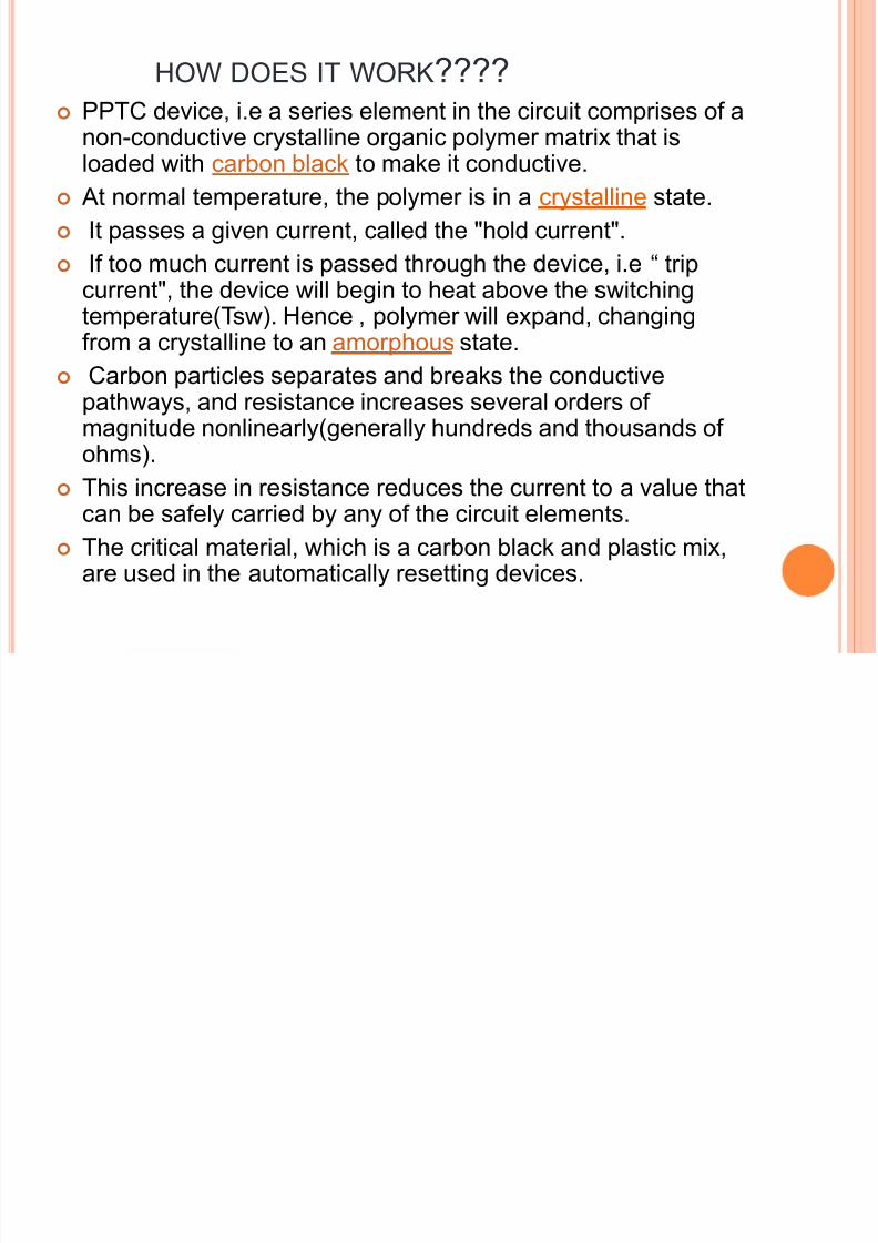
HOW DOES IT WORK???? PPTC device, i.e a series element in the circuit comprises of a
non-conductive crystalline organic polymer matrix that isloaded with carbon black to make it conductive.
At normal temperature, the polymer is in a crystalline state.
It passes a given current, called the "hold current".
If too much current is passed through the device, i.e “ tripcurrent", the device will begin to heat above the switchingtemperature(Tsw). Hence , polymer will expand, changingfrom a crystalline to an amorphous state.
Carbon particles separates and breaks the conductivepathways, and resistance increases several orders ofmagnitude nonlinearly(generally hundreds and thousands of
ohms). This increase in resistance reduces the current to a value that
can be safely carried by any of the circuit elements.
The critical material, which is a carbon black and plastic mix,are used in the automatically resetting devices.
8/11/2019 0811013118
http://slidepdf.com/reader/full/0811013118 6/21
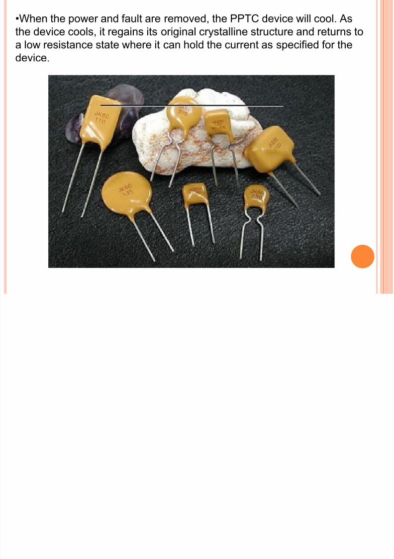
•When the power and fault are removed, the PPTC device will cool. As
the device cools, it regains its original crystalline structure and returns to
a low resistance state where it can hold the current as specified for the
device.

8/11/2019 0811013118
http://slidepdf.com/reader/full/0811013118 7/21

8/11/2019 0811013118
http://slidepdf.com/reader/full/0811013118 8/21
CHARACTERISTIC CURVES
Point 1 &2 are at normal condition, heat
generated is balanced with heat lost at
low temperature.
Increases in either current, ambient
temperature, or both will cause the
device to reach a temperature where
the resistance rapidly increases, as
shown in Point 3.
Hence it causes the device to
generate heat at a rate greater than
the rate at which heat can be
dissipated, thus causing the device to
heat up rapidly and increase inresistance(point 3 to4)for a very small
change in temperature.

8/11/2019 0811013118
http://slidepdf.com/reader/full/0811013118 9/21
………..CONTINUE
As long as the applied voltage remains at this level, the
device will remain in the tripped state . Once the voltage
decreases, the power is removed, and the device cools, thedevice will reset automatically.

8/11/2019 0811013118
http://slidepdf.com/reader/full/0811013118 10/21
CURRENT VS TIME GRAPH
At 75°C the heat input from the
environment is substantially greater
than it is at 0°C,
Additional I2R needed to trip the
device is less, resulting in a lower
trip current at a given trip time (or a
faster trip at given trip current).

8/11/2019 0811013118
http://slidepdf.com/reader/full/0811013118 11/21
APPLICATIONS
Battery protection(Cell phone,MP3 player, DSC’s)
IC protection
Protection of electrical equipments
Used in computer power supply due to PC97 standard(USB
Ports ,Firework ports , Disk drives)
Used in aerospace/nuclear application
Protecting audio speaker
Automotive electronics( Secutirysystem, Solenoid)
Telecommunication equipments( Faxes, Modem)

8/11/2019 0811013118
http://slidepdf.com/reader/full/0811013118 12/21
• AUTOMOTIVE APPLICATION
Protective devices that can be located
strategically throughout the vehicle can
help
reduce wire harness size and weight
8/11/2019 0811013118
http://slidepdf.com/reader/full/0811013118 13/21
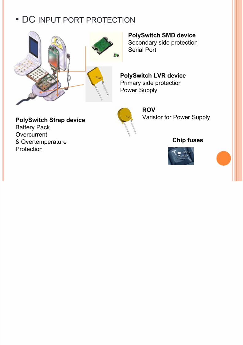
• DC INPUT PORT PROTECTION
PolySwitch SMD device
Secondary side protectionSerial Port
PolySwitch LVR device
Primary side protectionPower Supply
ROV
Varistor for Power Supply
Chip fuses
PolySwitch Strap device
Battery PackOvercurrent
& Overtemperature
Protection

8/11/2019 0811013118
http://slidepdf.com/reader/full/0811013118 14/21
•INDUSTRIAL APPLICATION
Power Management AC Mains
OC Protection
PolySwitch LVR device
Input PowerOV Protection
ROV
Power Driver
Protection
TRIAC, MOSFET, SCR
OC Protection
PolySwitch
LVR/RXE/RUE devices
Comms I/O
OC Protection
PolySwitchRXE, miniSMD
devices

8/11/2019 0811013118
http://slidepdf.com/reader/full/0811013118 15/21
•PPTC FOR BATTERY PROTECTION
PolySwitch Strap device
Battery Pack
Overcurrent
& Overtemperature
Protection
PolySwitch devices for battery protection
include SRP, LTP, LR4, VTP, VLP, VLR and
MXP series, disc, and special application
strap devices.

8/11/2019 0811013118
http://slidepdf.com/reader/full/0811013118 16/21
ADVANTAGES
Reduced warranty and service cost.
Protect against overcurrent in circuits and overtemperature in
motors.
Compactness
Increased product reliability
Withstand superior shock and vibration
Wide variety of applications as mentioned earlier. Resettability
Low resistance
Ideal for low voltage AC &DC

8/11/2019 0811013118
http://slidepdf.com/reader/full/0811013118 17/21
ADVANTAGES OVER OTHER FUSES
DEVICES PPTC CPTC BI-METAL CONVENT-
IONAL
RESETTAB-
LE
YES YES YES NO
SIZE SMALL MEDIUM LARGE LARGE
RESISTAN-
CE
LOW HIGH LOW LOW
POWERLOSS LOW HIGH LOW LOW
COST LOW MEDIUM HIGH HIGH

8/11/2019 0811013118
http://slidepdf.com/reader/full/0811013118 18/21
ADVANTAGE OF PPTC OVER CPTC
Application of CPTC(ceramic PTC) is limited due to
their relatively high operating temperature , highresistance and large size.
The composition of the CPTC device tends to be
brittle, which makes it vulnerable to damage from
shock, vibration.
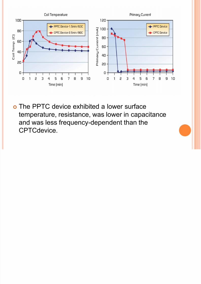
In an experiment, two identical transformers were
taken. The PPTC and the CPTC devices were
selected to have the same hold current.
A fault was created with a secondary short, while
current, coil temperature and time-to-trip were
measured.
8/11/2019 0811013118
http://slidepdf.com/reader/full/0811013118 19/21
The PPTC device exhibited a lower surfacetemperature, resistance, was lower in capacitance
and was less frequency-dependent than the
CPTCdevice.

8/11/2019 0811013118
http://slidepdf.com/reader/full/0811013118 20/21
CONCLUSION
Polymeric positive temperature coefficient device (poly
switch)is a resettable fuse. It is of less cost, small size and of many advantages as
mentioned in previous slides.
It’s applications and differences from other fuses make it very
popular and useful.
Its easy and cheap construction which does not requireextreme conditions add to its quality.

8/11/2019 0811013118
http://slidepdf.com/reader/full/0811013118 21/21
THANK YOU


