Embed Size (px)
Citation preview

AD-A 149 424 IAD
AD-EOI 271
TECHNICAL REPORT ARLCD-TR-84022
ELECTROMAGNETIC BRAKING OF AMETALLIC PROJECTILE IN FLIGHT
J. BENNETT
T. GORAP. J. KEMMEYW. J. KOLKERT DTIC
SELECTE)JAN 15 1985
DECEMBER 1984
U.S. ARMY ARMAMENT RESEARCH AND DEVELOPMENT CENTERLARGE CALIBER WEAPON SYSTEMS LABORATORY
DOVER, NEW JERSEY
APPROVED FOR PUBLIC RELEASE: DISTRIBUTION UNLIMITED.

4t
The views, opinions, and/or findings contained inIthis report are those of the author(s) and should
not be construed as an official Department of theArmy position, policy, or decision, unless so desig-nated by other documentation.
Destroy this report when no longer needed. Donot return to the originator.
I
- UNCLASSIFIEDSECURITY CLASSIFICATION OF THIS PAGE ("oen Deem Entered)
REPORT'DOCUMENTATION PAGE READ INSTRUCTIONSBEFORE COMPLETING FORM1. REPOR", NUMRF GO VT ACCESSION NO. 3. RECIPIENT'$ CATALOG NUMBER
Technical Report AR.D-TR-84022 7 -,4-A. TITLF 'ad S..btite) 5. TYPE OF REPORT & PERIOD COVERED
ELECTROMAGNETIC BRAKING OF A MEflTALLIC PROJECTILE 1 - 31 August 1983IN FLIGHT G. PERFORMING ORG. REPORT NUMBER
7. AUTH.OR(&) 8. CONTRACT OR GRANT NUMSER(e)
J. BennetL W. J. KolkertT. CoraP. J . Keiramey
9. PERFCRMING ORGANIZATION NAME AND ADDRESS 10. PROGRAM ELEMENT. PROJECT. TASKAREA & WORK UNIT NUMBERSARDC, LCWSL
Applied Science Division (SMCAR-LCA-G)Dover, INJ 07801-5001
11. CONTROLLING OFFICE NAME AND ADDRESS 12. REPORT DATE
ARDC, TSD December 1984STINFO Div (SIMCAR-TSS) 13. NUMBER OF PAGES
Doverc, NJ 07801-5001 1814. MONITORING AGENCY NAME a ADDRESS(if different fromn Controlling Office) 15. SECURITY CLASS. (of this report)
UnclassifiedIS. ECL ASSI FICATION/ DOWNGRADING
16. DISTRIBUTION STATEMENT (of this Report) SHDL
Approved f or public release; distribution is unlimited.
17. DISTRIBUTION STATEMENT (of the abstract entered In Block 20, If different from Report)
IS. SUPPLEMENTARY NOTES
W. J. Kolkert of the Prins Maurits Laboratorium THO, The Netherlands, served,is a Special Project Officer at ARDC.
1S. KEY wDOS (Continuev on revere side If necessary and IdentlY by block number)Decelderation RailgunM~agflutic field Flux compressionField diffusion joule heatingInductioni LinerSlldina corttact,3 Theta current
20. ABSTRACTr Catrtlut POW14 tevere t neceeevy ad Ideritify by block nimber)
Asimple m~cdel for the electromagnetic deceleration of a moving metallicprojectile is, described. This model incorporates the influence of magneticfield paramneters, time-dependent field diffusion, and device geometry toan;)poi~t h rkn cin The model predicts that a viable experi-mental bra~ing deViace can be designed.
AN7173EIINot O SISOSLT UNCLJASS IFIEDSEUURI? CLASSIFICATION OF THIS PAGC (When 3810 ffnteo"

CONTENTS
Page
introductionI
Modeling of Braking ActionI
Calculated Results4
Discussion 5
Conclusions 6
References 7
Distribution List 13
Acession For-TI SG CRA& IDTIC TAB
Unannouncedju3tif iC~t i
DTlC_SELECTEJAN 1 5 1985 3Availebilityc. s
DSs Avail ~~J'.Dis Bp;;Il
0 -.
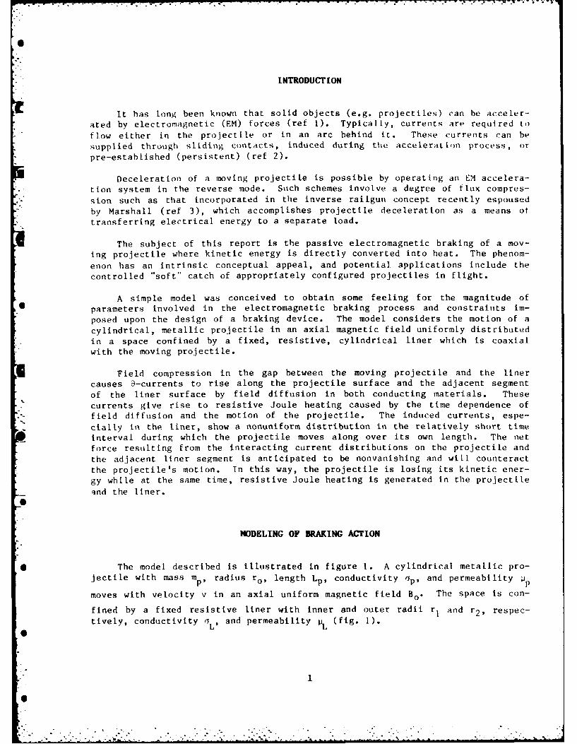
I NTRODU~T [ON
it has long been known that solid objects (e.g. projectiles) can be acceler-ated by electromagnetic (EM) forces (ref 1). Typically, current., are required toflow either in the projectile or in an arc behind it. These currents ran besupplied through sliding contacts, induced during the acceleration process, orpre-estabLished (persistent) (ref 2).
Deceleration of a moving projectile is possible by operating an EM accelera-tion system in the reverse mode. Suich schemes involve a degree of flux compres-
sion such as that incorporated in the inverse railgun concept recently espousedby Marshall (ref 3), which accomplishes projectile deceleration as a means oftransferring electrical energy to a separate load.
The subject of this report is the passive electromagnetic braking of a mov-ing projectile where kinetic energy is directly converted into heat. The phenom-
enon has an intrinsic conceptual appeal, and potential. applications include thecontrolled "soft" catch of appropriately configured projectiles in flight.
A simple model was conceived to obtain some feeling for the magnitude of6 parameters involved in the electromagnetic braking process and constraints im-
posed upon the design of a braking device. The model considers the motion of acylindrical, metallic projectile in an axial magnetic field uniformly distributedin a space confined by a fixed, resistive, cylindrical liner which is coaxialwith the moving projectile.
Field compression in the gap between the moving projectile and the linercauses 3-currents to rise along the projectile surface and the adjacent segmentof the liner surface by field diffusion in both conducting materials. Thesecurrents give rise to resistive Joule heating caused by the time dependence offield diffusion and the motion of the projectile. The induced currents, espe-cially in the liner, show a nonuniform distribution in the relatively short timeinterval during which the projectile moves along over its own length. The netforce resulting from the interacting current distributions on the projectile andthe adjacent liner segment is anticipated to be nonvanishing and will counteractthe projectile's motion. In this way, the projectile is losing its kinetic ener-gy while at the same time, resistive Joule heating is generated in the projectileqnd the liner.
hMODELING OF BRAKING ACrION
* The model described is illustrated in figure 1. A cylindrical metallic pro-
jectile with mass mp radius ro, length Lp. conductivity o. and permeabilityw
moves with velocity v in an axial uniform magnetic field Bo. The space is con-
fined by a fixed resistive liner with inner and outer radii r1 and r 2, respec-tively, conductivity i Lp and permeability 1i L (fig. 1).
6.°
|.'1
6"

*-*:--- --- *, - .. -. . ' - .i -, -7. . . -. . .- . . . - . - -• ," -- -
The field is assumed to be compressed discontinuously in the gap between the
projectile surface and the adjacent liner surface (radii ro and rl, respectively)at axial positions z, and z2 .
The motion of the projectile is hypothesized to be such that magnetic energyis conserved throughout the braking process. Neglecting mechanical work associ-ated with nonaxial forces on components, conservation of energy gives
m v -- (1)p St St
where H is the resistive Joule heating generated in the projectile and the linerduring braking.
The magnetic field in the gap between the projectile and the liner is ofinduction
r1B z = Bo0 2 2(2
for ro < r < r I and z I < z < z2 .
It is assumed that Bz is a constant during the braking process and that itsvalue is independent of the location on the surfaces of bordering projectile andliner.
For" radial diffusion of the magnetic field in the liner segment adjacent tothe moving projectile, the equation (ref 4)
z zr L L t 0
Sr
where
B (t = o) = o and B = B - BZ z z 0
Is valid.
Equation 3 leads to
B B (r) d,,4)
2

Ls
Equations 4 and 5 give;
"iB (rl) ___L _ (r r 2
z I 1L e 4 (r-r)()L = Tr t4t
)
Similar results are obtained for the induced currents in the projectile
where Bz is the magnetic field at the conductor surface. The heat generated per6H
unit time, 2 , in the conducting surfaces of projectile and liner bordering the
gap between them, is expressed by:
z [2r 2ir0 r 1 Jz2_2___ 2 dr+ o o 2
t-1 J'L J dr dz (7)
CO e
where 7, and ,Jp are the currents induced in the liner and projectile, respec-
tively, and where z2 - zI = Lp.
Equation 7 leads to
6H 2 r I B (r 2 I tJL
0LB2(r 2 a
z- fL Z 0L z I= __ f- 2 rr d z+ j L~ 'r
(B)
In performing the integration over z in equation 8, the time scale in the
liner segment covered by the moving projectile is running from zero to /v,
while the time scale for the generation in the projectile is running from the
S-beginning towards the end of the braking process (accumulation). The dynamics
mentioned here cause the nonuniform distribution of O-currents (eq 6) in the
liner segment adjacent to the moving projectile and are the source for a net
braking force on the projectile.
Combining equations I and 8 gives the analytical expression
y [PL v/2+ Bp (9)
describing the braking action in the chosen setup.
3
07

In equation 9, BL and a are
2lri L 2L (10)
2nr[B (r 1 2i= L (10)
27Tr B(r ° 2
". p
CALCULATED RESULTS
To obtain some feeling for the magnitude of parameters involved in electro-
magnetic braking, an example involving the motion of a cylindrical steel projec-
tile in an axial magnetic field in a space confined by a copper liner (fig. 1) is
* analyzed. Solving equation 9 numerically with a steel projectile mass mp - 6 kg,
length Lp = 0.508 m, radius ro = 0.0508 m, pp 2 x 10. Wb/A m, u = 0.38 x 10⁷
mho/m, and a copper liner with radius r 1 = 0.05334m, 1L = 12.57 x 10- 7 Wb/A m,
and a = 5.8 x 10⁷ mho/m gives the data of table I when braking action starts at
a projectile velocity vo = 600 m/s.
The length, AL, and time, At, involved in braking the projectile to a final
velocity of zero m/s and the overall heat generated in the liner, AHL) and the
* projectile, AH I are given in table 1. AL and At are calculated with equation 9p
(V,t - history), and AH and AH are calculated with equation 10.L p
Table 1. Electromagnetic braking action parameters for a steel projectileand copper liner
Magneticfield, Length, Time, Liner heat, Projectile heat,
Ro ,L At AHL AHP
(T) (i) (s) (J) 1)
1 12.9 34.5 x 10 - 3 1.079 x 10⁶ 50l4
2 3.1 8.7 x 10 - 3 1.079 x 10⁶ 1.01 x 10³
3 1.4 3.9 x 10- 3 1.078 x 10⁶ 1.5 x 10³
4

Keeping other parameters constant, the influence of gap-width (r, - re) onbraking length, AL,time, At, and heat generated in the projectile, AlIp, is Shown
in figures 2, 3, and 4, respectively.
If other materialq for projectile and liner are considered (e.g,., changingonly i and a with respect to values mentioned above), substantial changes in
braking length and time are calculated. If, for example, a tungsten projectileand copper liner are taken, braking lengths and times are reduced by a factor ofabout 2 to 3 and heat generated in the projectile is increased by a factor ofabout 1000. Taking a steel. liner and a steel or tungsten projectile increasesbraking lengths to many tens of meters and times to many seconds.
Although not indicated here numerically, the influence of projectile mass onbraking length and time appears to be almost proportional.
DISCUSSION
The model presented here contains a number of limitations. For instance, apractical device for electromagnetic braking of a metallic projectile would havea finite length. Braking the motion of the projectile on entering the magneticfield, present in the setup depicted in figure 1, is substantial and is not mod-eled here. During compression of the magnetic field in the gap between the mov-ing projectile and the liner, the change in magnetic induction is continuous [notdiscontinuous as assumed here (fig. 1)] and slightly different at the front andthe rear of the projectile. Although current distributions on liner and projec-tile surfaces will then be more complicated, as will force ilistributions, it isnot anticipated that calculated results will change drastically (i.e., not morethan a factor of two).
A more substantial limitation of the model is the assumption that Bz (mag-netic induction) in the gap is a constant during braking. As a result of diffu-sion of the B-field in the projectile and adjacent liner surfaces, B on these
surfaces will change not only in going from z, toward z, (fig. 1) but also duringthe whole braking process. Leakage of the compressed held from the gap causesless braking action than calculated. However, depending on the magnitude, thebraking time, At, leakage will have a minor influence on calculated parameters
when the associated skin depth [6 (6 - lAt/(1jo))] is smaller than the gap width(rj - re) considered. Application of the model presented here implies, there-
fore, that braking times in the order of a few milliseconds or less have to beconsidered. In addition, the effectiveness of the model may be further enhanced
by restricting attention to ferromagnetic projectiles. Apart from the limita-
tions mentioned above, the calculated results show that with realistic values forInitial magnetic induction and gap width, metallic projectiles with a mass andInitial velocity'of interest can be decelerated over an acceptable length.
in designing a device, the mechanical strength constraints related to theconstruction of the projectile to be decelerated, the liner and the B-field gen-erating coil have to he considered. In the gap between the moving projectile And
5
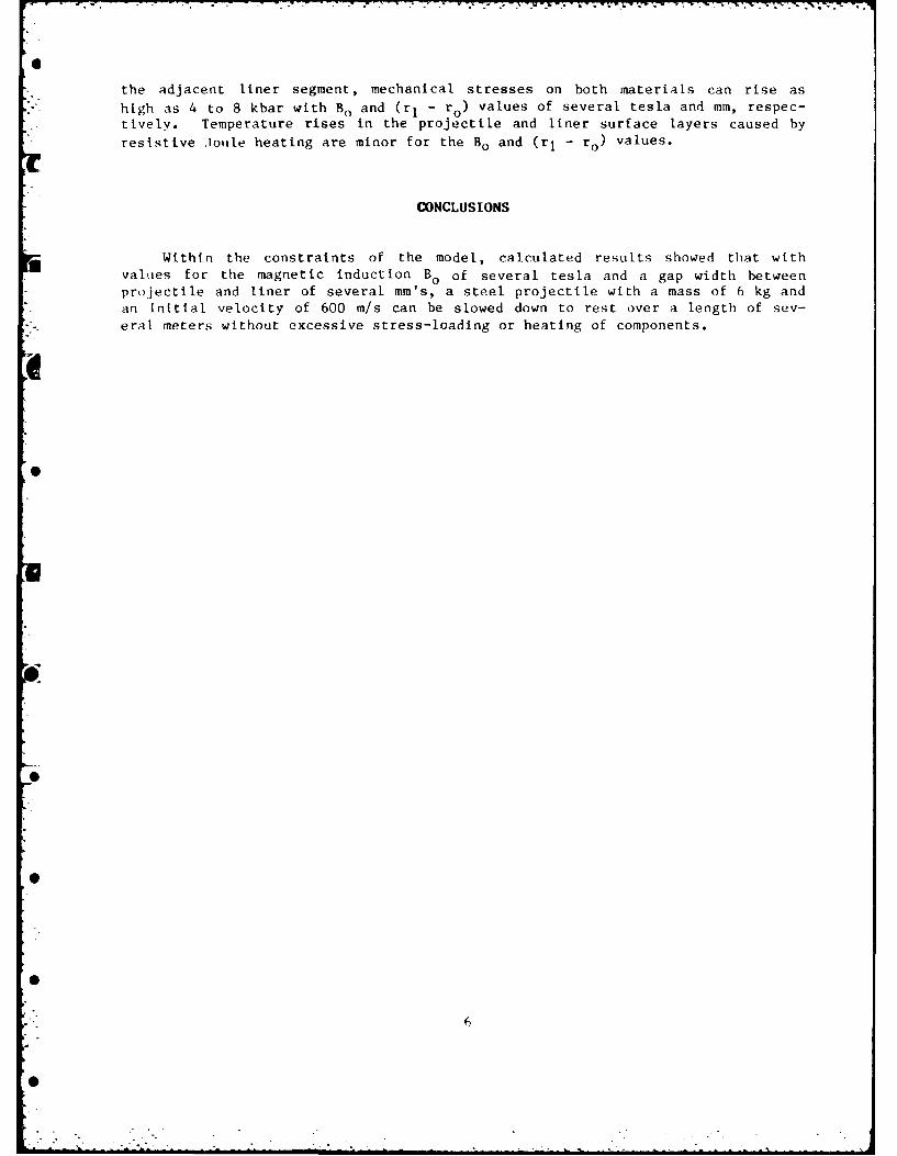
the adjacent liner segment, mechanical stresses on both materials can rise as
high as 4 to 8 kbar with B. and (r, - r o ) values of several tesla and mm, respec-tively. Temperature rises in the projectile and liner surface layers caused byresistive JToule heating are minor for the B. and (rI - ro ) values.
CONCLUSIONS
Within the constraints of the model, calculated results showed that with
values for the magnetic induction Bo of several tesla and a gap width betweenprojectile and liner of several mm's, a steel projectile with a mass of 6 kg and
an initial velocity of 600 m/s can be slowed down to rest over a length of sev-eral meters without excessive stress-loading or heating of components.
6

REFERENCES
1. 1980 Conference on Electromagnetic Guns anid Launchers, IEE,Trn. nMagnetics, vol 18, 1982, pp 3-216.
2. T. Gora and P 1. Keimey, I1EE, Trans. on Magnetics, vol 19, 1983, p) 1569.
3. R. A. Marshall, Second Symposium on Electromagnetir Launch Techn 1uuvBoston, MA, 10 - 13 October 1983, p 27.
4. .1. D). Jackson, Classical Elect rodynamics, second edition, A1. Wiley an(1 sonls,New York, NY, 1975.
7

N
.4
a:w I2
.4.4-
Uc~
Ic',j I.42N
I -4 ~
4~J I-
w-J
H(~)
N o.m -,
a 1Ea:
o I
NI onH ~U
0.)
0-H
I.. ~
j '-4 U
a)~4-
a)o
CN.~ - - .,~4 .4.~4~Ja)
on
-4
o * 0.)cn I U
on---4
9

100
BO 1 T
BO = 2T
E 10
I B30 = 3T
I
04 z
cc
aC
0 12 3 4 5GAP WIDTH, (rl ro), mm
Figure 2. Braking length 11 as a function of gap-width for a steel projectileand copper liner, Bo 1, 2, and 3T.
10

1000
Bo = 1T
100
Bo = 2TC
I ,- Bo = 3T<4
2 10
~z
1 -/
.1 c I I I
0 1 2 3 4 5
GAP WIDTH, (rl - ro), mm
Figure 3. Braking time At as a function of gap-width for a steel projectileand copper liner, B = 1, 2, and 3To
11
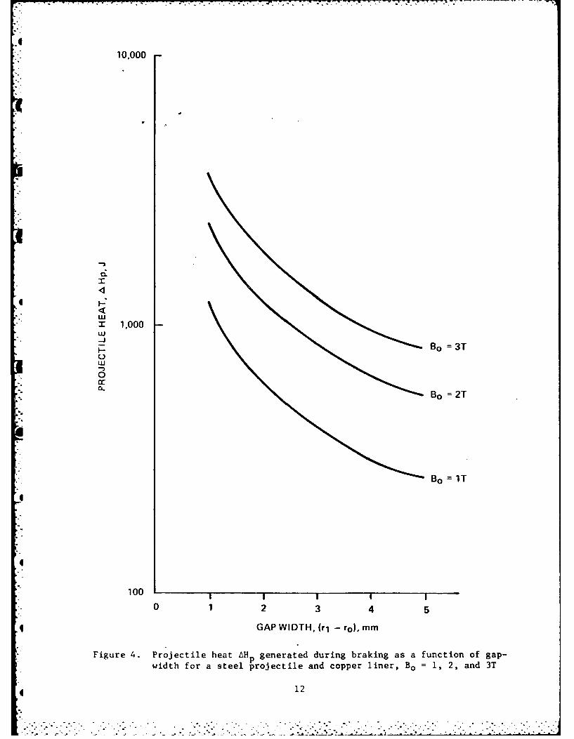
10.000
0.
m 1,000wi-J
1- Bo 3T
0
Bo 2T
B0 1 T
100 I
0 12 3 4 5
qGAP WIDTH, (rl -o) mm
Figure 4. Projectile heat AH p generated during braking as a function of gap-width for a steel projectile and copper liner, B = 1, 2, and 3T
4 12

DISTRIBUTION LIST
CommanderArmament Research and Development Center
U.S. Army Armament, Munitions and Chemical Command
ATTN: SMCAR-LCA-G (5)SMCAR-TSS (5)SMCAR-SF
Dover, NJ 07801-5001
CommanderU.S. Army Armament, Munitions and Chemical CommandATTN: AMSMC-GCL(D)
AMSMC-QAR-R(D)
Dover, NJ 07801-5001
AdministratorDefense Technical Information CenterATTN: Accessions Division (12)
Cameron StationAlexandria, VA 22314
DirectorU.S. Army Materiel Systems Analysis Activity
ATTN: DRXSY-MPAberdeen Proving Ground, MD 21005-5066
Commander/DirectorChemical Research and Development Center
U.S. Army Armament, Munitions and Chemical CommandATTN: SMCCR-SPS-I
SMCCR-RSP-AAPG, Edgewood Area, MD 21010-5423
DirectorBallistic Research LaboratoryATTN: AMXBR-OD-STAberdeen Proving Ground, MD 21005-5066
ChiefBenet Weapons Laboratory, LCWSLArmament Research and Development CenterU.S. Army Armament, Munitions and Chemical CommandATTN: SMCAR-LCB-TLWatervllet, NY 12189-5000
CommanderU.S. Army Armament, Munitions and Chemical CommandATTN: AMSMC-LEP-L
Rock Island, IL 61299-6000
13

DirectorU.S. Army TRADOC Systems
Analysis ActivityATTN: ATAA-SLWhite Sands Missile Range, NM 88002
DirectorDefense Advanced Research Projects AgencyATTN: DARPA-TTO, H. D. Fair, Jr.
1400 Wilson BoulevardArlington, VA 22317
CommanderBallistic Missile Defense System Command
ATTN: BMD/ATC-M, Darrell HarmonP.O. Box 1500
Huntsville, AL 35807
Center of ElectromechanicsATTN: W. Weldon
Taylor Hall 227University of Texas at AustinAustin, TX 78712
CommanderHQ, AFSC/DLWA
ATTN: CPT R. ReynoldsAndrews Air Force Base, MD 20334
L CommanderNaval Sea Systems CommandATTN: LCDR, Joseph R. CostaWashington, DC 20362
CommanderAir Force Armament Technology LaboratoryATTN: DLDG, Timothy AdenEglin Air Force Base, FL 32542
14
1-
I.
h.................


![D2 5001 E D2 5001 ES - Bekodownload.beko.com/Download.UsageManualsBeko/26011_D2-5001-E-Booklet-T… · d2 5001 e d2 5001 es %xodúÕn0dnlqhvl.xoodqpd.Õodyx]x / wihq|qfhexnÕodyx]xrnx\xq](https://img.dokumen.tips/doc/110x75/5e372291273b7c24bf3bd199/d2-5001-e-d2-5001-es-d2-5001-e-d2-5001-es-xodn0dnlqhvlxoodqpdodyxx-.jpg)


![Pemrograman Dasar [PTI-5001] 2012 - Universitas Brawijaya · 2017. 9. 13. · Pemrograman Dasar [PTI-5001] 2012. Pemrograman Dasar [PTI-5001] 2012. 1. Pada akhir pertemuan, diharapkan](https://img.dokumen.tips/doc/110x75/6122c225c81ad44d6b3aa618/pemrograman-dasar-pti-5001-2012-universitas-2017-9-13-pemrograman-dasar.jpg)