Embed Size (px)
Citation preview

Gæðaskjal (GSK) GSK-1265 Date of issue: 27.3.2014 Revision no.:2.0 Responsible: Einar Friðgeir Björnsson
Editor: Bjarni Ingi Björnsson
07-Instrumentation
L2 SCADA & L1 HMI CONFIG STANDARDS
Doc. no.: NA-07-STS011
This standard technical description is subject to change without prior notice. The most current issue will at all times be located on the Nordural web site, www.nordural.is.

L2 SCADA & L1 HMI CONFIG STANDARDS Doc.no. NA-07-STS011 Revision no.: 2.0
- 2/81 -
Contents
RESPONSIBILITY .................................... ........................................................... 8 1
INTRODUCTION ................................................................................................. 8 2
Document Purpose .................................. ............................................................. 9 2.1
Revision .......................................... ...................................................................... 9 2.2
Review ............................................ ....................................................................... 9 2.3
Abbreviations and Definitions ..................... ...................................................... 10 2.4
Plant System Architecture ......................... ........................................................ 11 2.5
System Objectives ................................. ............................................................. 12 2.6
Design Considerations.............................. ......................................................... 12 2.7
System requirements ............................... .......................................................... 13 2.8
Data Access Policies .............................. ............................................................ 14 2.9
Assumptions ....................................... ................................................................ 14 2.10
System Limit ...................................... ................................................................. 14 2.11
Symbol and standard library ....................... ...................................................... 14 2.12
SOFTWARE COMPONENTS ........................................................................... 15 3
Configuration and Programming Development Software ................................ 15 3.1
Software List ..................................... .................................................................. 15 3.2
SCADA Vendor Mandates ............................. ..................................................... 15 3.3
NAMING CONVENTIONS ................................................................................. 16 4
Area Naming Convention ............................ ....................................................... 16 4.14.1.1 Area code ................................................................................................... 17
FactoryTalk System Naming Conventions ............. .......................................... 17 4.2
FactoryTalk Naming Convention Structure Example ... .................................... 17 4.3
FTView Studio Applications Structure .............. ................................................ 18 4.4
FTView Studio Graphic Screen Naming Convention .... ................................... 19 4.5
FTView Studio Parameter Naming Convention ......... ....................................... 19 4.6
FTView Studio General Naming Convention ........... ......................................... 19 4.7
SCADA INTERFACE ................................... ..................................................... 20 5
FTView SE Language and Windows Regional Settings .. ................................. 20 5.15.1.1 Language ................................................................................................... 20
5.1.2 Windows Regional Settings ........................................................................ 21
SCADA Navigation Philosophy ....................... .................................................. 21 5.2
User Interface Design Standards ................... ................................................... 22 5.3
Graphic Screen Standard Colors .................... .................................................. 22 5.4
Graphic Screen Format ............................. ......................................................... 23 5.55.5.1 Zone 1: Title Bar ......................................................................................... 24
5.5.2 Zone 2: Alarm, Status and Navigation - ASN .............................................. 25
5.5.3 Zone 3: Process Display ............................................................................. 27
5.5.4 Zone 4: Function Bottom Bar ...................................................................... 29
5.5.5 Zone 5: Alarm Display Banner .................................................................... 31
L2 SCADA & L1 HMI CONFIG STANDARDS Doc.no. NA-07-STS011 Revision no.: 2.0
- 3/81 -
Main Alarm Summary Screen ......................... ................................................... 36 5.65.6.1 Configuration of the alarm summary ........................................................... 37
Alarm Summary popup ............................... ....................................................... 42 5.75.7.1 Alarm Class filtering .................................................................................... 42
Graphic Screen – View Types ....................... ..................................................... 42 5.85.8.1 Screen Navigation Hierarchy ...................................................................... 42
5.8.2 Overview .................................................................................................... 43
5.8.3 Sub Overview ............................................................................................. 44
5.8.4 Process Display .......................................................................................... 44
5.8.5 Popup Display ............................................................................................ 45
Graphic Screen – Static Object .................... ..................................................... 51 5.95.9.1 Static Element ............................................................................................ 52
5.9.2 Static Text .................................................................................................. 52
5.9.3 Process, Instrumentation and other Lines ................................................... 52
Graphic Screen- Dynamic Object .................... .................................................. 53 5.105.10.1 Equipment Dynamic Symbol ....................................................................... 54
5.10.2 Tank/Vessel Level Representation ............................................................. 55
5.10.3 Fault/Alarm Representation ........................................................................ 55
5.10.4 Multi-State Indicator .................................................................................... 56
5.10.5 Digital input Indicator .................................................................................. 56
5.10.6 Analog Value Indicator and Data Entry ....................................................... 57
5.10.7 Position Indicator ........................................................................................ 57
5.10.8 Level indicator ............................................................................................ 57
Group control ..................................... ................................................................ 58 5.11
Dynamic Object Configuration ...................... .................................................... 60 5.125.12.1 Global objects ............................................................................................. 60
Tooltips .......................................... ..................................................................... 61 5.13
Standard Buttons .................................. ............................................................. 61 5.14
PID Button ........................................ ................................................................... 61 5.15
Trends ............................................ ..................................................................... 62 5.16
Help page ......................................... ................................................................... 63 5.17
Sequence page ..................................... .............................................................. 64 5.18
Screen List ....................................... ................................................................... 64 5.19
CLX Network Overview .............................. ........................................................ 65 5.20
CLX Module details ................................ ............................................................ 66 5.21
ALARM MANAGEMENT .................................. ................................................ 67 6
Alarm states ...................................... .................................................................. 67 6.1
Event / Message Definition ........................ ........................................................ 67 6.2
Alarm Configuration ............................... ............................................................ 67 6.36.3.1 Alarm Severities ......................................................................................... 68
6.3.2 Alarm Definition .......................................................................................... 68
6.3.3 Alarm Class Definition ................................................................................ 69
6.3.4 Current Alarm Format ................................................................................. 69
6.3.5 Alarm Management .................................................................................... 69
6.3.6 FactoryTalk View Command ....................................................................... 69
Diagnostic Log Configuration ...................... ..................................................... 69 6.4
STARTUP AND SECURITY .............................. ................................................ 69 7
SCADA Start-up .................................... .............................................................. 69 7.1

L2 SCADA & L1 HMI CONFIG STANDARDS Doc.no. NA-07-STS011 Revision no.: 2.0
- 4/81 -
7.1.1 Servers ....................................................................................................... 70
Security .......................................... ..................................................................... 70 7.27.2.1 Security – Group and User ......................................................................... 70
7.2.2 FactoryTalk View SE Security – Service ..................................................... 70
7.2.3 FactoryTalk View SE Security – Run time .................................................. 71
7.2.4 Login/Logout............................................................................................... 72
7.2.5 FactoryTalk Security - Structure for the Start-up Phase .............................. 72
DeskLock .......................................... .................................................................. 73 7.3
HMI LEVEL 1 INTERFACE ............................. .................................................. 73 8
HMI Level 1 Navigation Philosophy.................. ................................................. 74 8.1
Graphic Screen Format ............................. ......................................................... 75 8.28.2.1 Zone 1: Title Bar ......................................................................................... 75
8.2.2 Zone 2: Main Button Bar ............................................................................. 75
8.2.3 Zone 3: Process Page ................................................................................ 75
Touch Screen Utilization .......................... .......................................................... 75 8.38.3.1 Minimum touch Area Size ........................................................................... 75
Application Naming ................................ ............................................................ 75 8.48.4.1 Runtime Application File ............................................................................. 76
Appendences ....................................... ............................................................ 77 9
Appendix A – Plant System Architecture Levels ..... ......................................... 77 9.1
Appendix B – Group Object ......................... ...................................................... 78 9.2
Appendix C – Objects provided with the Pilot Projec t ..................................... 80 9.3

L2 SCADA & L1 HMI CONFIG STANDARDS Doc.no. NA-07-STS011 Revision no.: 2.0
- 5/81 -
Table of figures Figure 1 – Plant System Architecture Levels ............................................................................ 12
Figure 2 – FactoryTalk Naming Structure ................................................................................. 17
Figure 3 – FTView Studio Applications Structure ..................................................................... 18
Figure 4 – Language settings with English (United States), en-US as a standard .................... 21
Figure 5 – FactoryTalk View SE standard color pallet .............................................................. 23
Figure 6 – Graphic screen zone defnition ................................................................................. 24
Figure 7 – Zone 1 Title bar ....................................................................................................... 24
Figure 8 – Zone 2 ASN bar ...................................................................................................... 25
Figure 9 – Zone 2 ASN buttons ................................................................................................ 26
Figure 10 – Zone 3 process display example ........................................................................... 27
Figure 11 – Zone 3 Display settings, properties tab settings .................................................... 28
Figure 12 – Zone 3 Display settings, behavior tab settings ...................................................... 28
Figure 13 – Zone 4 function bottom bar ................................................................................... 29
Figure 14 – Zone 4 Side bar ..................................................................................................... 29
Figure 15 – Zone 4 Bottom bar display settings, properties tab settings ................................... 31
Figure 16 – Zone 5 alarm display banner ................................................................................. 31
Figure 17 – Zone 5 Alarm panel properties settings in general tab ........................................... 32
Figure 18 – Zone 5 Alarm panel properties settings in columns tab ......................................... 33
Figure 19 – Zone 5 Alarm panel properties settings in event subscription tab .......................... 34
Figure 20 – Zone 5 Alarm panel properties settings in states tab ............................................. 34
Figure 21 – Alarm and events color pallet. ............................................................................... 35
Figure 22 – Zone 5 Alarm panel properties settings in common tab ......................................... 36
Figure 23 – Alarm summary page ............................................................................................ 36
Figure 24 – Alarm summary properties settings in appearance tab .......................................... 37
Figure 25 – Alarm summary properties settings in columns tab ............................................... 38
Figure 26 – Alarm summary properties settings in toolbar tab .................................................. 39
Figure 27 – Alarm summary properties settings in status bar tab ............................................. 39
Figure 28 – Alarm summary properties settings in event subscriptions tab .............................. 40
Figure 29 – Alarm summary properties settings in sort tab ....................................................... 40
Figure 30 – Alarm summary properties settings in states tab ................................................... 41
Figure 31 – Alarm summary properties settings in behavior tab ............................................... 41
Figure 32 – Alarm summary popup .......................................................................................... 42
Figure 33 – Screen navigation hierarchy .................................................................................. 43
Figure 34 – Overview page ...................................................................................................... 43
Figure 35 – Sub overview page ................................................................................................ 44
Figure 36 – Process display page ............................................................................................ 45
Figure 37 – Popup display button bar ....................................................................................... 45
Figure 38 – Popup display operator tab for an analog indicator ................................................ 46
Figure 39 – Popup display operator tab for a motor ................................................................. 46
Figure 40 – Popup display maintenance tab for an analog indicator ......................................... 47
Figure 41 – Popup display maintenance tab for a valve ........................................................... 47
Figure 42 – Popup display engineering tab for a valve ............................................................. 48
Figure 43 – Popup display trends tab for an analog indicator ................................................... 48
Figure 44 – Popup display alarm configuration tab for an analog indicator ............................... 49
Figure 45 – Popup display alarm tab for an analog indicator .................................................... 49
Figure 46 – Example of a permissive popup ............................................................................ 50
Figure 47 – Example of an interlock popup .............................................................................. 51
Figure 48 – Process page static objects ................................................................................... 51
Figure 49 – Recommended process line sizes ......................................................................... 52
Figure 50 – Process line navigation arrows .............................................................................. 53
Figure 51 – Example of an equipment dynamic symbol ........................................................... 54
Figure 52 – Tank/Vessel representation ................................................................................... 55
Figure 53 – Alarm representation in object and in equipment popup ........................................ 56
Figure 54 – Example of multi-state indicators ........................................................................... 56
Figure 55 – Digital input indicator ............................................................................................. 57
Figure 56 – Analog value indicator ........................................................................................... 57

L2 SCADA & L1 HMI CONFIG STANDARDS Doc.no. NA-07-STS011 Revision no.: 2.0
- 6/81 -
Figure 57 – Position indicator ................................................................................................... 57
Figure 58 – Level indicator with limit alarms ............................................................................. 58
Figure 59 – Group control faceplate ......................................................................................... 58
Figure 60 – Group control popup faceplate .............................................................................. 60
Figure 61 – Example of tooltips ................................................................................................ 61
Figure 62 – PID popup home tab ............................................................................................. 62
Figure 63 – PID popup maintenance tab .................................................................................. 62
Figure 64 – Trend configuration runtime tab settings ............................................................... 63
Figure 65 – Help page example ............................................................................................... 64
Figure 66 – Sequence Screen Example ................................................................................... 64
Figure 67 – Screen list ............................................................................................................. 65
Figure 68 – CLX overview ........................................................................................................ 66
Figure 69 – Stratix switch Popup .............................................................................................. 66
Figure 70 – Task monitor popup .............................................................................................. 66
Figure 71 – CLX Module Detail ................................................................................................ 67
Figure 72 – Diagnostic Log Configuration settings ................................................................... 69
Figure 73 – FactoryTalk View SE Security users ...................................................................... 71
Figure 74 – Current user function call ...................................................................................... 72
Figure 75 – Login popup .......................................................................................................... 72
Figure 76 – FactoryTalk Security workgroups .......................................................................... 73
Figure 77 – HMI level 1 ............................................................................................................ 74
Figure 78 – Plant System Architecture Levels, large figure ...................................................... 77

L2 SCADA & L1 HMI CONFIG STANDARDS Doc.no. NA-07-STS011 Revision no.: 2.0
- 7/81 -
Table of tables Table 1 – PlantPAx documents .................................................................................................. 8
Table 2 – Application revisions ................................................................................................... 9
Table 3 – Abbreviations and Definitions ................................................................................... 10
Table 4 – Plant System Architecture Levels ............................................................................. 11
Table 5 – Software list .............................................................................................................. 15
Table 6 – SCADA Vendor Mandates ........................................................................................ 15
Table 7 – Example of associated screen table for the functional description ............................ 16
Table 8 – Area codes definition ................................................................................................ 17
Table 9 – Graphic screen standard colors ................................................................................ 23
Table 10 – Zone 2 ASN button states ...................................................................................... 26
Table 11 – Zone 4 Side bar button description ......................................................................... 30
Table 12 – Zone 5 Alarm panel properties settings in columns tab ........................................... 33
Table 13 – Zone 5 RGB parameters for Alarm and events color pallet. .................................... 35
Table 14 - Zone 5 severity configuration, colors refer to colors in Figure 21 ............................. 35
Table 15 – Alarm summary properties settings in columns tab ................................................. 38
Table 16 – Static elements text sizes and color ........................................................................ 52
Table 17 – Material color pallet ................................................................................................ 53
Table 18 – Process page indication for status/quality ............................................................... 54
Table 19 – Process page indication for mode .......................................................................... 54
Table 20 – Process page indication for maintenance bypass ................................................... 55
Table 21 – Process page indication for state ............................................................................ 55
Table 22 – Position indicator color pallet .................................................................................. 57
Table 23 – Level indication color pallet .................................................................................... 58
Table 24 – Group control modes .............................................................................................. 59
Table 25 – Group control states ............................................................................................... 59
Table 26 – Group control extra buttons .................................................................................... 60
Table 27 – Alarm states and indication .................................................................................... 67
Table 28 – Alarm severity categorization.................................................................................. 68
Table 29 – FactoryTalk View SE Security code ........................................................................ 71
Table 30 – Commissioning FT accounts .................................................................................. 72
Table 31 – Group states ........................................................................................................... 78
Table 32 – Group Val notify states ........................................................................................... 79
Table 33 – Graphic displays provided with the pilot project ...................................................... 80
Table 34 – Global objects provided with the pilot project .......................................................... 81
Table 35 – Images provided with the pilot project ..................................................................... 81
Table 36 – Parameter files provided with the pilot project ........................................................ 81
L2 SCADA & L1 HMI CONFIG STANDARDS Doc.no. NA-07-STS011 Revision no.: 2.0
- 8/81 -
RESPONSIBILITY 1This Standard Technical Specification (STS) is of responsibility of the owner. The revision and date of issue are on the front page.
All deviations from the specifications must be approved in writing by the Owner.
INTRODUCTION 2This document objective is to show the standard design, screen layout and operation for both HMI and SCADA systems on the Norðurál Site.
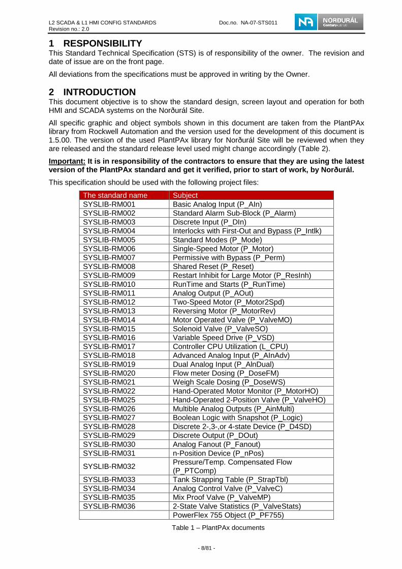
All specific graphic and object symbols shown in this document are taken from the PlantPAx library from Rockwell Automation and the version used for the development of this document is 1.5.00. The version of the used PlantPAx library for Norðurál Site will be reviewed when they are released and the standard release level used might change accordingly (Table 2).
Important: It is in responsibility of the contracto rs to ensure that they are using the latest version of the PlantPAx standard and get it verifie d, prior to start of work, by Norðurál.
This specification should be used with the following project files:
The standard name Subject SYSLIB-RM001 Basic Analog Input (P_AIn) SYSLIB-RM002 Standard Alarm Sub-Block (P_Alarm) SYSLIB-RM003 Discrete Input (P_DIn) SYSLIB-RM004 Interlocks with First-Out and Bypass (P_Intlk) SYSLIB-RM005 Standard Modes (P_Mode) SYSLIB-RM006 Single-Speed Motor (P_Motor) SYSLIB-RM007 Permissive with Bypass (P_Perm) SYSLIB-RM008 Shared Reset (P_Reset) SYSLIB-RM009 Restart Inhibit for Large Motor (P_ResInh) SYSLIB-RM010 RunTime and Starts (P_RunTime) SYSLIB-RM011 Analog Output (P_AOut) SYSLIB-RM012 Two-Speed Motor (P_Motor2Spd) SYSLIB-RM013 Reversing Motor (P_MotorRev) SYSLIB-RM014 Motor Operated Valve (P_ValveMO) SYSLIB-RM015 Solenoid Valve (P_ValveSO) SYSLIB-RM016 Variable Speed Drive (P_VSD) SYSLIB-RM017 Controller CPU Utilization (L_CPU) SYSLIB-RM018 Advanced Analog Input (P_AInAdv) SYSLIB-RM019 Dual Analog Input (P_AlnDual) SYSLIB-RM020 Flow meter Dosing (P_DoseFM) SYSLIB-RM021 Weigh Scale Dosing (P_DoseWS) SYSLIB-RM022 Hand-Operated Motor Monitor (P_MotorHO) SYSLIB-RM025 Hand-Operated 2-Position Valve (P_ValveHO) SYSLIB-RM026 Multible Analog Outputs (P_AinMulti) SYSLIB-RM027 Boolean Logic with Snapshot (P_Logic) SYSLIB-RM028 Discrete 2-,3-,or 4-state Device (P_D4SD) SYSLIB-RM029 Discrete Output (P_DOut) SYSLIB-RM030 Analog Fanout (P_Fanout) SYSLIB-RM031 n-Position Device (P_nPos)
SYSLIB-RM032 Pressure/Temp. Compensated Flow (P_PTComp)
SYSLIB-RM033 Tank Strapping Table (P_StrapTbl) SYSLIB-RM034 Analog Control Valve (P_ValveC) SYSLIB-RM035 Mix Proof Valve (P_ValveMP) SYSLIB-RM036 2-State Valve Statistics (P_ValveStats) PowerFlex 755 Object (P_PF755)
Table 1 – PlantPAx documents

L2 SCADA & L1 HMI CONFIG STANDARDS Doc.no. NA-07-STS011 Revision no.: 2.0
- 9/81 -
Document Purpose 2.1
The objectives of this document are to:
• Define the user interface for the HMI and SCADA system
• Define the standards for graphic displays including templates, screen navigation, graphical objects and coding standard for the Rockwell SCADA system.
• Provide naming conventions for all pre mentioned points.
Revision 2.2
Applicable revisions 01.11.2011 28.08.2013 TBC TBC
SCADA Standard 1.0 2.09
PlantPAx 1.5 2.09
Table 2 – Application revisions
Review 2.3
A review of this standard will be carried out at least each January and the standard will be updated accordingly.

L2 SCADA & L1 HMI CONFIG STANDARDS Doc.no. NA-07-STS011 Revision no.: 2.0
- 10/81 -
Abbreviations and Definitions 2.4
Abbreviations Definitions ADS Active Directory Service AOI Add-on Instructions ASN Alarm, Status and Navigation CIP Control and Information Protocol CLX ControlLogix processor/system CV Control Variable DATA RSLinx Enterprise I/O Server DHCP Dynamic Host Configuration Policy DNS Domain Naming Service ERP Enterprise Resource Planning
EVRSI EV – EverLock RSI - Rockwell Software Incorporated
FT Factory Talk FTAP Factory Talk automation Platform FTD Factory Talk Directory FTHistorian The Rockwell Historian server
FTView The FTView servers manage the process screen for the SCADA Client
GRT Norðurál Grundartangi
HMI
Human Machine Interface HMI refers to plant operator stations installed locally nearby a machine on the process floor and consists of PanelView Plus units (level 1)
ISC Initial Starting Conditions MES Manufacturing Execution System ME Machine Edition HMI System
OPC Object Linking and Embedding for Process control – Administered by OPC foundation
PID Proportional Integral and Derivative control PIDE Proportional Integral and Derivative control Enhanced P&ID Process and Instrumentation Diagram PLC Programmable Logic Controller PV Process Variable PV+ PanelView Plus, MMI RNA Rockwell Network Architecture
SCADA Supervisory Control and Data Acquisition SCADA refers to the Control Rooms computer systems running FTView applications (Level 2)
SAP ERP software applications used by Norðurál (SAP: Business Software Solutions Applications and Services)
SE Supervisory Edition SCADA System SFC Sequential Function Chart SOP Standard Operating Procedure SP Set point UDT User–Defined Data Type VBA Visual Basic for Applications VLAN Virtual Area Network VTP VLAN Trunk Protocol
Table 3 – Abbreviations and Definitions

L2 SCADA & L1 HMI CONFIG STANDARDS Doc.no. NA-07-STS011 Revision no.: 2.0
- 11/81 -
Plant System Architecture 2.5
The plant system architecture is divided into five (5) levels:
Level Designation Hardware/Software Objectives
5 Enterprise Management
SAP-ERP-SOP Platforms
Commercial business systems
3 & 4 Production Execution Management
FTHISTORIAN Software Platforms Metrics Vantage Point MES Applications
Area, line, and cell business management and optimization
2 Process Supervisory
FTView SE Platforms (server, workstation, thin clients) Printers
Real time supervisory execution control / SCADA
1 Direct Execution Level
PLC/CLXs Embedded platforms - HMI Control and I/O Networks I/O Adapters
The Direct Execution level represents the controlling and monitoring functions of the process that are typically implemented by the Programmable Logic Controllers (PLCs) and direct machine level Operator interfaces.
0 Field I/O Field I/O, VFDs, Instrumentation, Instrumentation (sensors, actuators and transmitters)
Physical, I/O, and instrumentation interaction with the plant
Table 4 – Plant System Architecture Levels
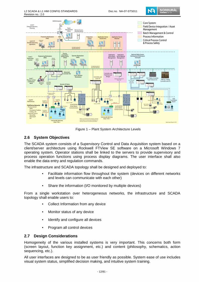
Figure 1 shows these levels in more detail (see 9.1 Appendix A – Plant System Architecture Levels for larger figure):
L2 SCADA & L1 HMI CONFIG STANDARDS Doc.no. NA-07-STS011 Revision no.: 2.0
- 12/81 -
Figure 1 – Plant System Architecture Levels
System Objectives 2.6
The SCADA system consists of a Supervisory Control and Data Acquisition system based on a client/server architecture using Rockwell FTView SE software on a Microsoft Windows 7 operating system. Operator stations shall be linked to the servers to provide supervisory and process operation functions using process display diagrams. The user interface shall also enable the data entry and regulation commands.
The infrastructure and SCADA topology shall be designed and deployed to:
• Facilitate information flow throughout the system (devices on different networks and levels can communicate with each other)
• Share the information (I/O monitored by multiple devices)
From a single workstation over heterogeneous networks, the infrastructure and SCADA topology shall enable users to:
• Collect Information from any device
• Monitor status of any device
• Identify and configure all devices
• Program all control devices
Design Considerations 2.7
Homogeneity of the various installed systems is very important. This concerns both form (screen layout, function key assignment, etc.) and content (philosophy, schematics, action sequencing, etc.).
All user interfaces are designed to be as user friendly as possible. System ease of use includes visual system status, simplified decision making, and intuitive system training.

L2 SCADA & L1 HMI CONFIG STANDARDS Doc.no. NA-07-STS011 Revision no.: 2.0
- 13/81 -
The default language shall be in English but all text shall also be translated to Icelandic and the language switching feature of the FTView SE utilized.
Operator ergonomics must be a priority. The user interface must be as user friendly as possible but the main focus will be user functionalities and ergonomics.
Process screens must remain as simple as possible in order to:
• Minimize future maintenance,
• Reduce risks of deficiencies hence delays at start-up,
• Facilitate reaching homogeneity between the systems,
• Facilitate screen design by the Vendors.
Recommended actions to reach these objectives:
• When necessary, 3-D drawings might be used for static objects to increase process understanding and facilitate process operations. However, the drawings must not impact SCADA performance excessively.
• VBA code use must be kept to a minimum. Before any use of VBA code the Vendor needs permission from the owner.
• Picture files are to be kept to a minimum to not impact performance excessively.
• Standard objects shall be used as the norm.
• Vendor’s logo is not allowed in the SCADA system except on the help page where vendor’s company contact information is obligatory.
At the end of delivery of the SCADA system the owner of the system will be Norðurál. The full SCADA application backup with all associated files shall be supplied to Norðurál.
System requirements 2.8
The availability of the SCADA system is crucial for the operation, maintenance and monitoring of the Norðurál Site. It shall have a high availability and a very quick restart time in case of failures. The SCADA system will be distributed on multiple servers to minimize the risk of a whole plant failure.
Startup of the whole SCADA system after a shutdown should not take longer than 10 min.
The refresh rate of a display shall not be greater than 2 sec.
Each graphic display in an application can contain up to 1000 references to expressions or tags (HMI tags and data server tags). This limit includes the tags contained in embedded variables. This level should be avoided at all cost.
The limit also includes duplicate references. For example, one display can contain only 1000 numeric inputs that refer to tags, even if all 1000 objects refer to the same tag.
• Number of alarms per FactoryTalk application should not be greater than 20.000
• Number of alarms per Rockwell Automation Device Server (RSLinx Enterprise) should not be greater than 10.000
• Number of alarms per Tag Alarm and Event Server should not be greater than 10.000
• Alarm burst (number of alarms occurring at once) the maximum is 2.000
• Number of alarms the alarm summary can display at once is 2.000
• 20 clients can simultaneously connect to the application

L2 SCADA & L1 HMI CONFIG STANDARDS Doc.no. NA-07-STS011 Revision no.: 2.0
- 14/81 -
Data Access Policies 2.9
To ensure a maximum level of information sharing, users with the appropriate privileges can access all process pages for a specific area.
Write access is restricted to user groups having operative authority with the following types of data:
• Set point modifications
• Commands, starts and stops for the equipment and line (group)
• Operation mode modifications
• Alarm acknowledgments and control
• Other specific cases according to area requirements
• Equipment configuration (includes naming, labeling etc.) through popups
Assumptions 2.10
This document takes into account the following assumptions:
• SCADA user interface screens are designed for use with a resolution of 1920 x 1080 pixels
• Control layer (PLCs) for the Norðurál Site shall be according to the Norðurál standard
System Limit 2.11
SCADA systems do NOT:
• Perform control functions, control algorithms, or become involved in the PLC calculations
• Perform calculations or data transformation for the ControlLogix or for other systems
• Provide long-term data storage. Use historians.
• Produce reports
• The SCADA system doesn’t store equipment labeling, description or tag names, only the connection to the equipment (tag) in the specific PLC. The PLC stores this information where they are configured from the SCADA system.
Symbol and standard library 2.12
VERY IMPORTANT: Vendors are not allowed to modify the standard library elements along with screen and popup standards. These screens and objects are used in all areas of the plant. If Vendors have a specific requirement, they can copy and rename the object, and send this object to the owner for validation.

L2 SCADA & L1 HMI CONFIG STANDARDS Doc.no. NA-07-STS011 Revision no.: 2.0
- 15/81 -
SOFTWARE COMPONENTS 3
Configuration and Programming Development Software 3.1
As standard, all configuration and programming shall be done utilizing the basic development software levels (0 thru 2). The software shall form the basic configuration and application development core for level 0 thru 2 configuration and programming. A list of the applicable software is provided in Table 5.
Software List 3.2
The following software shall be used for the application development:
Software Vendor Version Patch release
RSLogix5000 Rockwell 20.01 -
RSNetworx for Ethernet/IP Rockwell 11.0 -
RSNetworx for ControlNet Rockwell 11.0 -
RSNetworx for DeviceNet Rockwell 11.0 -
FactoryTalk View ME Rockwell 6.10 Jun 2013
FactoryTalk View SE Rockwell 6.10 Jun 2013
Table 5 – Software list
SCADA Vendor Mandates 3.3
The SCADA vendors must provide the following documentation in English.
Title Document Number Type Functional Description Document Simulation procedure Document Factory Acceptance Test (FAT) Document Site Acceptance Test (SAT) Document Fault and Alarm List Excel All other documents included in the contract
Table 6 – SCADA Vendor Mandates
The Functional Description shall include following information;
• Description for new elements. If Vendors create a new element (modification of the PlantPAx object is not allowed).
• Documentation of new HMI tags and their function and use.
• Description of non-standard buttons and their function (see Table 7 – Example of associated screen table for the functional description for an example).
• Description of associated pages; navigation buttons and buttons which call non-standard pages or popups, for each page the vendor provides with the system (see Table 7 – Example of associated screen table for the functional description for an example).

L2 SCADA & L1 HMI CONFIG STANDARDS Doc.no. NA-07-STS011 Revision no.: 2.0
- 16/81 -
Button label or Description Function Associated
Screens Navigation arrow 1 Displays Blower Room page GRT40_S002 Navigation arrow 2 Displays Silo control page GRT40_S010 PID Button Displays PID popup GRT40_P100 Control Button 1 Displays Silo control popup for
Silo 1 GRT40_P102
Control Button 2 Displays Silo control popup for Silo 2
GRT40_P103
Pump 1 out button Takes pump out of control -
Table 7 – Example of associated screen table for the functional description
The Vendor must also provide the following services:
• Programming to support the MES command, set point, and requirement (if required)
• Support for the MES configuration
• Support for the PLC configuration when needed
• All other activities included in the contract
NAMING CONVENTIONS 4This section covers the naming conventions for the data acquisition and the database process variables. Also included are the FTView SE application graphic screens and other component naming conventions.
Here are some general rules:
• Equipment identification tags shall be as defined in the P&ID drawings and project standards
• All names in the FTView SE development environment i.e. Screen Names, Server names etc. shall be in English US
• All text in a graphic display, alarms, tags and static text shall be in English and in Icelandic.
• No special characters (#, $, etc.) may be entered other than “_” (this is the only character allowed as a text separator)
Area Naming Convention 4.1
An FTView SE application may be divided into several sub areas. Within a process area, there will therefore be at least one FTView server pair and/or one or more DATA server pairs. Sub area names are very important because FTView SE uses the name of each sub area to resolve the component references. With the sub area name, FTView SE is allowed to find the source of each element on the screen.
The Area FTView server shall adhere to the following structure:
GRT – Grundartangi
HEL – Helguvík
VLI - Vlissigen
Where
• GRTxx : “GRT” is always present for Grundartangi site and “xx” refers to the specific area number

L2 SCADA & L1 HMI CONFIG STANDARDS Doc.no. NA-07-STS011 Revision no.: 2.0
- 17/81 -
4.1.1 Area code Following table shows the area code for Norðurál Site
Area code Area 00 General 10 Utilities 20 Administration 30 Material handling 40 Power 50 Reduction 60 Anode production 70 Casting 80 Environmental 90 SCADA library objects
Table 8 – Area codes definition
FactoryTalk System Naming Conventions 4.2
The following FTView FactoryTalk System naming conventions shall be used for each system identified for a specific area.
GRTxx_yyy..yyy_zzzzz
Where:
• GRTxx : “GRT” is always present and “xx” refers to the specific area number
• yyy..yyy : refers to the area or sub area name (Short title with a maximum 22 characters and no spaces)
• zzzzz: refers to the server type ID
The following server type ID’s shall be used in FTView applications
• DATA I/0 Server
• HIST Historian Acquisition Node (OPC)
• HMI FTView Server, SCADA Graphics
• ALARM for alarm server
FactoryTalk Naming Convention Structure Example 4.3
Each data server (OPC or RSLinx Enterprise) must be placed in its own area separated from the FTView Server. A typical example of FTView structure is shown below:
Figure 2 – FactoryTalk Naming Structure
FactoryTalk project shall be grouped into areas but it can contain different sub areas.

L2 SCADA & L1 HMI CONFIG STANDARDS Doc.no. NA-07-STS011 Revision no.: 2.0
- 18/81 -
Each area in a plant may contain one or more Data Access servers and at least 1 FTView server.
FTView Studio Applications Structure 4.4
FTView application formats shall be developed by FTView Studio and distributed in each FactoryTalk area. A system is initially developed separate from the final area based deployment. In addition, the overall FactoryTalk Directory and naming must be maintained. Each separate development must use the same FactoryTalk naming conventions for both area and sub area naming contexts.
Vendors must obtain confirmation of its FTView application structure from owner before programming starts to ensure that all structure elements (Application name, sub-areas, FTView and Data access server names) are in conformity with project specification and standards. These elements must be included in the functional description. This is required since often different vendors will supply systems that need to be integrated into the same FTD. By not complying with this rule, the vendor may have to change the structure and be responsible to modify all parameter files and dynamic objects configuration of its application.
Figure 3 – FTView Studio Applications Structure
The example shown above is a typical SCADA project outline where:
(1) Is FTView Application Name
(2) Are the Areas and Sub-areas
(3) Are the FTView Server and Data Access Server
(4) Are the Process Displays (Line or Unit)
1 3
4
2
5
4a
4b
4c

L2 SCADA & L1 HMI CONFIG STANDARDS Doc.no. NA-07-STS011 Revision no.: 2.0
- 19/81 -
(4a) Included special popups (marked EFLA the vendor), (4b) Included PlantPAx popups and screens (marked RA) and (4c) Process displays, popups and etc.
(5) Is the FTView Alarm Server
FTView Studio Graphic Screen Naming Convention 4.5
Graphic screens must be named using a short descriptive name. The screen name must be prefixed with the area or sub area abbreviation.
The graphic screen naming convention structure is defined as follows:
GRTxx_Zxxx_ AAAAAAAAAAAAAAAAA
Where:
• GRTxx: “GRT” is always present and “xx” refers to the specific area number
• Zxxx: Z is the type of view (see list below) and xxx refers to the screen number (always 3 numbers and each screen number is unique)
o O: Overview
o P: Popup
o S: Process display screen
o T: Template
o X: General full page: Tools, Background, Alarm History, Trend, Network Diagnostics
o G: Global Object
• xxxxxxxxxxxxxx Refers to the short title with a maximum 30 characters and no spaces. This section shall be logical and meaningful. Standard keywords, prefixes, suffixes should be used to help grouping.
Popups and overview pages can bare the GRTxx name of the main area as they are called from various sub areas.
FTView SE uses the “gfx” file extension; these screens must be saved with this native format as standard.
If the images, macros, and the VBA are relative to a specific screen the “FTView Studio General Naming Convention” must be used (see chapter 4.7).
Vendors are not allowed to modify the elements in the PlantPAx library. Vendors can copy the common elements (popup and template) to a project and save them under a different name for a specific requirement. This has to be informed to Norðurál and a change description should be included.
Vendors are advised to use predefined global objects such as buttons and indicators as building blocks for their user developed popups as much as they can, as this will help to update the system in the future.
FTView Studio Parameter Naming Convention 4.6
Parameter files are normally not used in the SCADA system as global object usage is the norm. But if needed they are allowed, please see chapter 4.7 for naming conventions.
FTView Studio General Naming Convention 4.7
To facilitate the application integration, the following elements in FTView studio must respect the same general naming convention:
• Images (general)

L2 SCADA & L1 HMI CONFIG STANDARDS Doc.no. NA-07-STS011 Revision no.: 2.0
- 20/81 -
• Macros (general)
• Global Objects (ASN Control)
• Parameter files
The General naming convention structure is defined as follows:
GRTxx_Yyyy_xxxxxxxxxxxxxxxxxxxxx
Where:
• GRTxx : “GRT” is always present and “xx” refers to the specific area number
• Yyyy: Y is always present. yyy is a number (always 3 numbers and each number is unique)
o I: Images
o M: Macro
o G: Global object
o F: Parameter File
• xxxxxxxxxxxxxx: refers to the short title with a maximum of 30 characters and no spaces. This section shall be logical and meaningful. Standard keywords, prefixes, suffixes should be used to enhance grouping.
Example:
GRT90_G800_”short description”
SCADA INTERFACE 5This section includes detailed information about SCADA graphical interfaces (screens).
FTView SE Language and Windows Regional Settings 5.1
5.1.1 Language The standard language for Norðurál Site is “English (United States), en US” since that is the default language of the PlantPAx library.
Language used to configure an FTView application must be the same for all FTView Studio applications developed for Norðurál Site to avoid problems with text displaying.
In FTView SE Studio “English (United States), en-US” must be selected when a new application is created. See Figure 4:

L2 SCADA & L1 HMI CONFIG STANDARDS Doc.no. NA-07-STS011 Revision no.: 2.0
- 21/81 -
Figure 4 – Language settings with English (United States), en-US as a standard
5.1.2 Windows Regional Settings During development or at run time, FactoryTalk View uses the Windows regional settings for the current application language to enter, modify, or display text in an application.
For Norðurál Site Windows regional settings must be configured as follows:
• For Time:
o Short time HH:mm
o Long time HH:mm:ss
• For date:
o Short date d.M.yyyy
o Long date dd.MM.yyyy
SCADA Navigation Philosophy 5.2
The SCADA Navigation philosophy includes the following important points:
• General process overviews shall always be available.
• The main button bar is located at the bottom of all pages except the Overview. This button bar has the same functionality for all sub areas. The bar presents a predefined setup of buttons, an alarm button a trend button, a print screen button and an info details button.
• The ASN Control is located below the header of each page and provides statuses and overall alarms for all units of a specific line (group). All lines and units are shown simultaneously with the ASN Control.
• Clicking on the ASN Control prompts the display of a specific line process main page or a specific unit detail.
• A line (group) can be operated from a process display screen. A line control standard display shall have an interlock popup a permissive popup (both

L2 SCADA & L1 HMI CONFIG STANDARDS Doc.no. NA-07-STS011 Revision no.: 2.0
- 22/81 -
accessible inside the line control popup) and a fault/alarm symbol. In addition, it shall provide the line (group) status.
• Equipment symbols display the equipment status with a symbol color. Other related information such as modes, faults/alarms, permissive and interlocks are shown around the equipment symbol as a series of smaller icons.
• Popup window layout and content are consistent for any specific type of equipment in all plant areas.
• Analog value trends are accessed by clicking on the analog value within any process display screen.
Accomplishment of these points ensures that the resulting product is both user friendly and a key provider of essential operational information. All relevant and important details are immediately accessible during the use of the SCADA application in all areas of the plant.
User Interface Design Standards 5.3
The main function of the SCADA system is the process representation. The objective is to group information required by the plant facility users into graphic screens for optimal plant facility operation.
Graphic screens shall be written in simple English and Icelandic (User can choose language) to provide operators with the options available within the specific graphic user interface.
Graphic screens shall be as simple as possible with access to essential information in a pyramid approach.
Graphic screens shall be designed using one or more of the following configurations:
• Overview to assist the operator in understanding area control
• Standard navigation button bar
• Standard status bar (Alarm, Status and Navigation - ASN)
• Simplified block diagram to illustrate sequences, interactions, and selected options
• Diagrammatic representation of the process using predetermined symbols to represent the process or various equipment (process display screen)
• Faults and alarms shall always be disassociated from state representation (running, stopped etc.) to simplify the understanding of equipment functioning. Faults/alarms shall be represented by fault/alarm icons or buttons. Equipment states shall be represented by changing color symbols.
• Command buttons shall be invisible to indicate when the command is not available from the SCADA or HMI.
• Diagnostic process screens will assist Maintenance/Operations with troubleshooting problems such as:
o ControlLogix (CLX) Network Diagnostics
o Emergency Stops (localization)
Graphic Screen Standard Colors 5.4
The following section defines the color palette that shall be used for all types of graphic screens or objects found in the Norðurál project.

L2 SCADA & L1 HMI CONFIG STANDARDS Doc.no. NA-07-STS011 Revision no.: 2.0
- 23/81 -
The color palette shall be standard for all areas of the plant. FTView by default has a standard color palette.
Colors for the Norðurál project (standard) are defined by index codes. These codes represent the line and column number of the FTView SE color palette.
Figure 5 – FactoryTalk View SE standard color pallet
Standard colors for the Norðurál project are defined in Table 9:
Index
Name Code Index
Name Code Index
Name Code
1 Dark red L3C3 11 Yellow L2C1 21 Cyan L2C5 2 Red L1C9 12 Orange L3C8 22 Aqua
marine L2C6
3 Grey L1C6 13 Violet L2C9 23 Dark Olive Green
L2C4
4 Background Light Grey
L1C3 14 Blue L5C4 24 Electrical Green
L4C9
5 Grey L1C4 15 Midnight Blue
L2C8 25 Deep Purple
L5C9
6 Dark Grey L1C5 16 Light Blue L2C7 26 Dark Grey L1C7 7 Off White L1C2 17 Mid Blue L5C3 27 Wheat L3C6 8 White L1C1 18 Light
Orange L3C7 28 Thistle L5C6
9 Dark Green L4C8 19 Dark Brown
L3C9 29 Black L1C8
10 Light Green
L2C2 20 Gold L3C8
Table 9 – Graphic screen standard colors
Important: The color pallet for the graphic screens and animation do not match with the color pallet in the Alarms and events, therefore are the Alarms and events color pallet is custom made. The pallet has 6 custom made colors see Figure 21 and those colors are the only one that is used in the Alarm and events color pallet. RGB parameters for the custom made colors are in Table 13.
Graphic Screen Format 5.5
The SCADA process shall be supervised at the basic device level in the process display screen during operation. Equipment or line (group) control shall be possible from the process display screen. Static and dynamic objects shall be organized according to the various guidelines provided below.
The standard graphic screen is split up in 5 zones. Zones 1, 2, 4 and 5 are always visible but zone 3 is a process display. The popup shall be displayed over the process display (zone 3). Equipment control, interlock or equipment fault/alarm popup shall be used to supplement full size screens by offering the operator quick access to related information or commands.

L2 SCADA & L1 HMI CONFIG STANDARDS Doc.no. NA-07-STS011 Revision no.: 2.0
- 24/81 -
Figure 6 – Graphic screen zone defnition
The basic graphic screen zones are:
• Zone 1: Title Bar and General Information
• Zone 2: Alarm, Status and Navigation (ASN)
• Zone 3: Process Display
• Zone 4: Function Buttons
• Zone 5: Alarms Banner
5.5.1 Zone 1: Title Bar
Figure 7 – Zone 1 Title bar
Zone 1 is always visible at the top of each graphic screen and it shows following general information
1. Time and date shall be programmed with a “Time Date Display Properties” object and indicated as following.
DD/MM/YYYY HH:MM:SS TT DD = day of the month (2 characters), MM = month number (2 characters), YYYY = year (4 characters), HH = hour of the day (2 characters), MM = minutes of the hour (2 characters), SS = seconds of the minutes (2 characters). TT = AM/PM Only visible when English language is selected.
2. Logout button:
Makes following actions:
a. Logs out the current SE Client
L2 SCADA & L1 HMI CONFIG STANDARDS Doc.no. NA-07-STS011 Revision no.: 2.0
- 25/81 -
b. Aborts the current process screen
c. Displays the current process screen again
This is done to secure that the current user rights show only the corresponding objects connected to that user.
3. Languages buttons give users a choice between two languages Icelandic and English. Default languages settings shall be English US and the chosen language shall effects all text on all screens.
4. Graphic Screen shall identify the plant facility or the functional section (follow the project specification for naming conventions). The corresponding FTView display number shall also be displayed to the right side of the Graphic Screen title as follows:
Example: Fresh and Reacted Alumina
5. The corresponding FTView display number shall be displayed.
Example: [GRT90_S100]
6. User Name/Login Button: indicates the user currently logged in. This field is dynamically linked to the “CurrentUserName()” FTView system functions. A click on the button will call the following function:
a. Calls a login macro which calls the login popup
b. Aborts the current process screen
c. Displays the current process screen again
This is done to secure that the current user rights show only the corresponding objects connected to that user.
Background panels and Time and Date indicators are allowed to be global objects, other objects in Zone 1 should not be a part of global object as they are current process page depended.
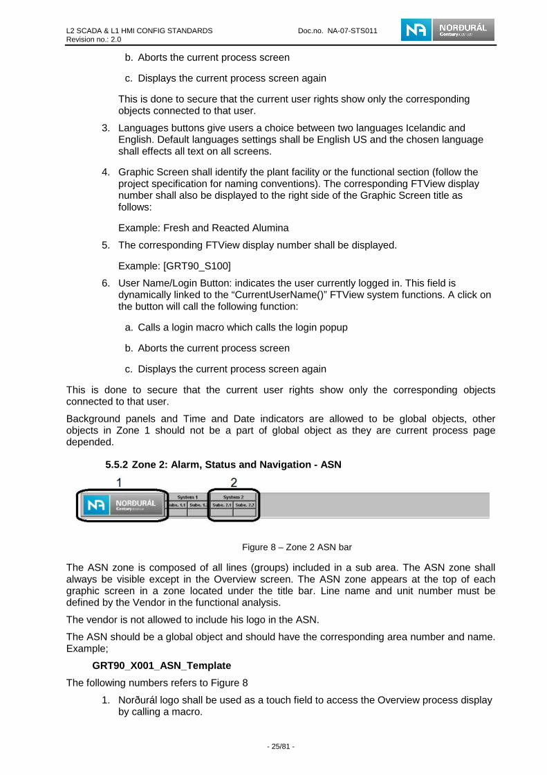
5.5.2 Zone 2: Alarm, Status and Navigation - ASN
Figure 8 – Zone 2 ASN bar
The ASN zone is composed of all lines (groups) included in a sub area. The ASN zone shall always be visible except in the Overview screen. The ASN zone appears at the top of each graphic screen in a zone located under the title bar. Line name and unit number must be defined by the Vendor in the functional analysis.
The vendor is not allowed to include his logo in the ASN.
The ASN should be a global object and should have the corresponding area number and name. Example;
GRT90_X001_ASN_Template
The following numbers refers to Figure 8
1. Norðurál logo shall be used as a touch field to access the Overview process display by calling a macro.
L2 SCADA & L1 HMI CONFIG STANDARDS Doc.no. NA-07-STS011 Revision no.: 2.0
- 26/81 -
2. The ASN Control is a Global Object (FTView Studio). It shall be included in each page and it is used to represent the line status (fault/alarm) and states (running, stopped etc.). The ASN control corresponds to a line (group). Some ASN controls shall be grouped according to the workshop or logical groups. All graphic screens shall contain an Alarm status and Navigation zone (ASN) consisting of a series of buttons. The ASN control shall respect general naming convention.
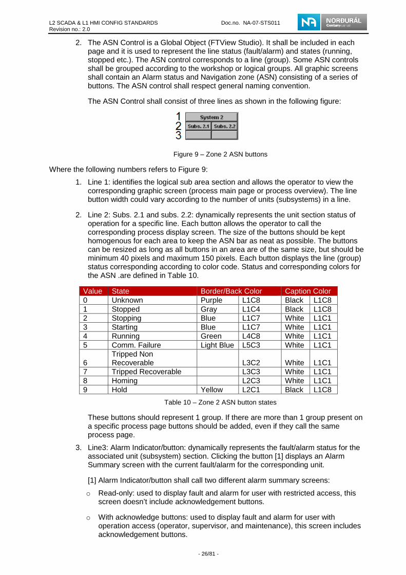
The ASN Control shall consist of three lines as shown in the following figure:
Figure 9 – Zone 2 ASN buttons
Where the following numbers refers to Figure 9:
1. Line 1: identifies the logical sub area section and allows the operator to view the corresponding graphic screen (process main page or process overview). The line button width could vary according to the number of units (subsystems) in a line.
2. Line 2: Subs. 2.1 and subs. 2.2: dynamically represents the unit section status of operation for a specific line. Each button allows the operator to call the corresponding process display screen. The size of the buttons should be kept homogenous for each area to keep the ASN bar as neat as possible. The buttons can be resized as long as all buttons in an area are of the same size, but should be minimum 40 pixels and maximum 150 pixels. Each button displays the line (group) status corresponding according to color code. Status and corresponding colors for the ASN .are defined in Table 10.
Value State Border/Back Color Caption Color 0 Unknown Purple L1C8 Black L1C8 1 Stopped Gray L1C4 Black L1C8 2 Stopping Blue L1C7 White L1C1 3 Starting Blue L1C7 White L1C1 4 Running Green L4C8 White L1C1 5 Comm. Failure Light Blue L5C3 White L1C1
6 Tripped Non Recoverable L3C2 White L1C1
7 Tripped Recoverable L3C3 White L1C1 8 Homing L2C3 White L1C1 9 Hold Yellow L2C1 Black L1C8
Table 10 – Zone 2 ASN button states
These buttons should represent 1 group. If there are more than 1 group present on a specific process page buttons should be added, even if they call the same process page.
3. Line3: Alarm Indicator/button: dynamically represents the fault/alarm status for the associated unit (subsystem) section. Clicking the button [1] displays an Alarm Summary screen with the current fault/alarm for the corresponding unit.
[1] Alarm Indicator/button shall call two different alarm summary screens:
o Read-only: used to display fault and alarm for user with restricted access, this screen doesn’t include acknowledgement buttons.
o With acknowledge buttons: used to display fault and alarm for user with operation access (operator, supervisor, and maintenance), this screen includes acknowledgement buttons.

L2 SCADA & L1 HMI CONFIG STANDARDS Doc.no. NA-07-STS011 Revision no.: 2.0
- 27/81 -
If the specific process page doesn’t include group control, a group AOI should even though be present in the PLC where the equipment on that process page is connected indicates all statuses (alarm, starting, stopping, etc.) of the process page. For the alarm summary screens to view only the alarms subjected to the specific process page an alarm filter has to be activated. In the alarm and event setup the alarms have to be setup with alarm class. The filter is activated by writing the corresponding alarm class name in a tag. This is described in chapter 5.7.1 Alarm Class filtering. These buttons should represent 1 group. If there is more than 1 group present on the specific process page an alarm indicator/button should be added and the filtering should than be dependent on the group not the process page.
For details on the Group control animation see Appendix B – Group Object.
5.5.2.1 ASN naming convention The ASN naming convention structure is defined as follows:
GRTxx_Yyyy_xxxxxxxxxxxxxxxxxxxxx
Where:
• GRTxx : “GRT” is always present and “xx” refers to the specific area number
• Yyyy: Since the ASN will be a Global Object the it should be labeled with a G. yyy is a number (always 3 numbers and each number is unique)
• xxxxxxxxxxxxxx: refers to the short title with a maximum of 30 characters and no spaces. This section shall be logical and meaningful. Standard keywords, prefixes, suffixes should be used to enhance grouping. Usually this should be ASN_Areadescription
Example: GRT90_G001_ASN_Template
5.5.3 Zone 3: Process Display
Figure 10 – Zone 3 process display example
The process display screen represents the monitored process status or Operation Support screen. A process display screen may include menus, sub-menus, detailed application views, trend views, graphs, and any other graphics that represent the monitored process. The zone may contain control device symbols (i.e. group control button and statuses display) graphs, blocks of text, and other graphic objects.
The group control display shall always be located in the top left section of Zone 3, when applicable. If there is more than 1 group present on the process page a group control displays should be added, forming a row at the top. It is allowed to locate the Group control button close

L2 SCADA & L1 HMI CONFIG STANDARDS Doc.no. NA-07-STS011 Revision no.: 2.0
- 28/81 -
to a specific group if there is more than one group in a process display and it improves process readability and understanding see chapter 5.11 for more details.
5.5.3.1 Process Display FTView SE Display Settings For proper operation, the settings shown in Figure 11 and Figure 12 shall be used for the Process Display Settings in the FTView SE:
Figure 11 – Zone 3 Display settings, properties tab settings
Figure 12 – Zone 3 Display settings, behavior tab settings
Background color should be gray L1C3 refer to Table 9.

L2 SCADA & L1 HMI CONFIG STANDARDS Doc.no. NA-07-STS011 Revision no.: 2.0
- 29/81 -
5.5.4 Zone 4: Function Bottom Bar
Figure 13 – Zone 4 function bottom bar
This zone shall always be visible for each specific sub area’s graphic screen except in the Overview screen.
1. These two buttons give a popup for alarm and trends. The alarm popup will display the current alarm list which is active for the sub area and the trend popup will display historian tag trends.
Alarm button shall call two different alarm summary screens:
• Read-only: used to display fault and alarm for user with restricted access, this screen doesn’t include acknowledgement buttons.
• With acknowledge buttons: used to display fault and alarm for user with operation access (operator, supervisor, and maintenance), this screen includes acknowledgement buttons.
No filtering other than area connection should be activated by calling these alarm summary screens.
2. Print screen button calls the print dialogue to print the current visible screen.
3. The Info Details button shall call a popup list as the following figure shows:
Figure 14 – Zone 4 Side bar
The Function button in the popup list shall contain buttons used to perform common operator functions.

L2 SCADA & L1 HMI CONFIG STANDARDS Doc.no. NA-07-STS011 Revision no.: 2.0
- 30/81 -
Action commands associated with the function buttons shall have the same application definition for all plant sub areas.
The Function bottom bar shall respect the following rules:
• Button positions and size is fixed
• Standard button names are static
• Vendor can use the spare unmarked buttons bars (with the approval of the owner).
• If the spare unmarked buttons are not used they must be deleted and the drop up list sized corrected accordingly. It is not allowed to add more buttons than are apparent in the template.
The following table lists the function buttons that are usually present on the drop up list:
Button label Function Unused buttons Free use Help Support Screen for all beneficial information for the operator
or maintenance person. Screen List Displays a button page with all graphic screens contained in
the sub area Overview Displays the area overview Sub Overview Displays the sub area overview Emergency stop Displays the localization of the emergency stop CLX Network Overview
Displays area network and equipment statuses
CLX module Details Displays the modules communicating with the area CLX (local and remote racks, including IO‘s and communication modules)
Home Windows Displays the overview Shutdown Client Open a popup to select shutdown client or abort.
Table 11 – Zone 4 Side bar button description
5.5.4.1 Bottom Bar FTView SE Display Settings The following figure shows the configuration required for the FTView SE bottom bar.

L2 SCADA & L1 HMI CONFIG STANDARDS Doc.no. NA-07-STS011 Revision no.: 2.0
- 31/81 -
Figure 15 – Zone 4 Bottom bar display settings, properties tab settings
Background color should be gray L1C5 refer to Table 9.
5.5.5 Zone 5: Alarm Display Banner
Figure 16 – Zone 5 alarm display banner
This zone shall be the same for all the graphic screens in a specific sub area and shall always be visible except in the Overview screen.
The alarm banner should be large enough to display three (3) lines for fault/alarm indications. Acknowledgement of alarms is not available from the alarm banner.

L2 SCADA & L1 HMI CONFIG STANDARDS Doc.no. NA-07-STS011 Revision no.: 2.0
- 32/81 -
5.5.5.1 The general tab
Figure 17 – Zone 5 Alarm panel properties settings in general tab
Alarm and Event Summary Command should be left unfilled as there are 2 alarm summaries due to user depended restrictions.
Background color should be same gray as the background color in process pages L1C3 (red: 224, green: 224 and blue:224).
Row double click should be set to Run Alarm Command. This is configured for individual alarm in the alarm and event setup, where it opens the corresponding equipment process page.
The text in the alarm summary banner should be set to Arial Bold 10 (see Table 16). The banner indicates this as 9.75 pt. as it connected to the height of the banner.

L2 SCADA & L1 HMI CONFIG STANDARDS Doc.no. NA-07-STS011 Revision no.: 2.0
- 33/81 -
5.5.5.2 Columns tab
Figure 18 – Zone 5 Alarm panel properties settings in columns tab
The following table indicates which columns should be visible and the correct settings for these columns. The banner cannot be configured in the same way as the main alarm summary as the banner has not the same pixel width.
Column Width Align Format Priority 30 Left Icon Severity 50 Left Number Alarm State 30 Left Icon In alarm Time 135 Left Short Date +
Time Alarm Name 260 Left Text Message 540 Left Text
Table 12 – Zone 5 Alarm panel properties settings in columns tab
5.5.5.3 Status bar All objects should be checked except Silence All Alarms and Audible Sound Enabled.
5.5.5.4 Event Subscriptions tab Should be configured for the subarea;

L2 SCADA & L1 HMI CONFIG STANDARDS Doc.no. NA-07-STS011 Revision no.: 2.0
- 34/81 -
Figure 19 – Zone 5 Alarm panel properties settings in event subscription tab
5.5.5.5 States Tab For proper operation, the Alarm Banner Color Configuration shall be as shown below for FTView SE.
Figure 20 – Zone 5 Alarm panel properties settings in states tab
As the Figure 20 shows there are four types of alarm urgent, high, medium and low and the table and figure below shows the color code for each alarm see chapter 6 for alarm classifications.

L2 SCADA & L1 HMI CONFIG STANDARDS Doc.no. NA-07-STS011 Revision no.: 2.0
- 35/81 -
Important: The color pallet for the graphic screens and animation do not match with the color pallet in the Alarms and events, therefore are the Alarms and events color pallet in the pilot project custom made. The pallet has 6 custom made colors ( see Figure 21) and those colors are the only one which is used in the Alarm and events color pallet. RGB parameters for the custom made colors are in Table 13
Figure 21 – Alarm and events color pallet.
Color Red Green Blue Blue 0 136 200
Yellow 255 255 0 Red 255 0 0
Purple 192 0 192 Black 0 0 0 Gray 224 224 224
Table 13 – Zone 5 RGB parameters for Alarm and events color pallet.
Table 14 shows severity configuration for alarms.
In alarm unacknowledged Color text Color
background Blink
Urgent (severity 4) 5 4 Yes High (severity 3) 5 3 Yes
Medium (severity 2) 5 2 Yes Low (severity 1) 5 1 Yes
In alarm acknowledged Color text Color background Blink
Urgent 5 4 No High 5 3 No
Medium 5 2 No Low 5 1 No
Normal Unacknowledged Color text Color
background Blink
Urgent 4 6 No High 3 6 No
Medium 2 6 No Low 1 6 No
Table 14 - Zone 5 severity configuration, colors refer to colors in Figure 21
5.5.5.6 Common Tab Common tab should be configured as following.

L2 SCADA & L1 HMI CONFIG STANDARDS Doc.no. NA-07-STS011 Revision no.: 2.0
- 36/81 -
Figure 22 – Zone 5 Alarm panel properties settings in common tab
Main Alarm Summary Screen 5.6
The Main Alarm Summary screen displays current fault/alarm conditions and shall be configured as shown in pilot project. The Main Alarm Summary screen shall be accessed by the alarm button located on the bottom bar (sub area filtered fault/alarm).
Two screens are provided in this standard; one for user with acknowledges rights and one for read only access. The read only alarm summary doesn’t display acknowledge buttons and alarms therefore cannot be acknowledged.
Figure 23 – Alarm summary page
From this screen, the Historical Alarm, Fault, Message and Event Viewing Utility can be used to complete the following actions:
• Retrieve data by selecting the start date/time and end date/time

L2 SCADA & L1 HMI CONFIG STANDARDS Doc.no. NA-07-STS011 Revision no.: 2.0
- 37/81 -
• View the alarm history
• View the event history
• Sort data according to its description, tag name
• Filter specific group alarms
• Print the data with a standard windows printer
The color configuration for the Alarm Summary screen shall be the same as defined for the alarm Table 14.
By double-clicking on an alarm in the alarm summary the specific equipment process display should be called see chapter 6.3.6
5.6.1 Configuration of the alarm summary
5.6.1.1 Appearance tab
Figure 24 – Alarm summary properties settings in appearance tab
Background color should be same gray as the background color in process pages L1C3 (red: 224, green: 224 and blue: 224). Text color is Black
The text in alarm summary banner should be set to Arial Bold 10 (see Table 16). The banner indicates this as 9.75 pt. as it connected to the height of the banner.

L2 SCADA & L1 HMI CONFIG STANDARDS Doc.no. NA-07-STS011 Revision no.: 2.0
- 38/81 -
5.6.1.2 Columns tab
Figure 25 – Alarm summary properties settings in columns tab
The following table indicates which columns should be visible and the correct settings for these columns.
Column Width Align Format Priority 30 Left Icon Severity 50 Left Number Alarm State 30 Left Icon Event Time 135 Left Short Date +
Time In Alarm Time 135 Left Short Date +
Time Acknowledge Time
135 Left Short Date + Time
Out of Alarm Time 135 Left Short Date + Time
Area 260 Left Text Alarm Name 240 Left Text Message 540 Left Text Alarm Count 70 Left Text Alarm Class 120 Left Text
Table 15 – Alarm summary properties settings in columns tab
5.6.1.3 Toolbar tab In the alarm summary which is called for user with acknowledge rights all buttons are checked. For the alarm summary with only read only access the Acknowledge, Suppress, Disable and Reset buttons are not visible as the following figure shows;

L2 SCADA & L1 HMI CONFIG STANDARDS Doc.no. NA-07-STS011 Revision no.: 2.0
- 39/81 -
Figure 26 – Alarm summary properties settings in toolbar tab
Row double click should be set to Run Alarm Command. This is configured for individual alarm in the alarm and event setup, where it should open the corresponding equipment process page.
5.6.1.4 Status bar tab All panels are checked
Figure 27 – Alarm summary properties settings in status bar tab
5.6.1.5 Event Subscriptions tab Subscriptions are for the specific sub area.

L2 SCADA & L1 HMI CONFIG STANDARDS Doc.no. NA-07-STS011 Revision no.: 2.0
- 40/81 -
Figure 28 – Alarm summary properties settings in event subscriptions tab
5.6.1.6 Sort tab First is sort by Severity – Descending and then by Event Time – Descending.
Figure 29 – Alarm summary properties settings in sort tab
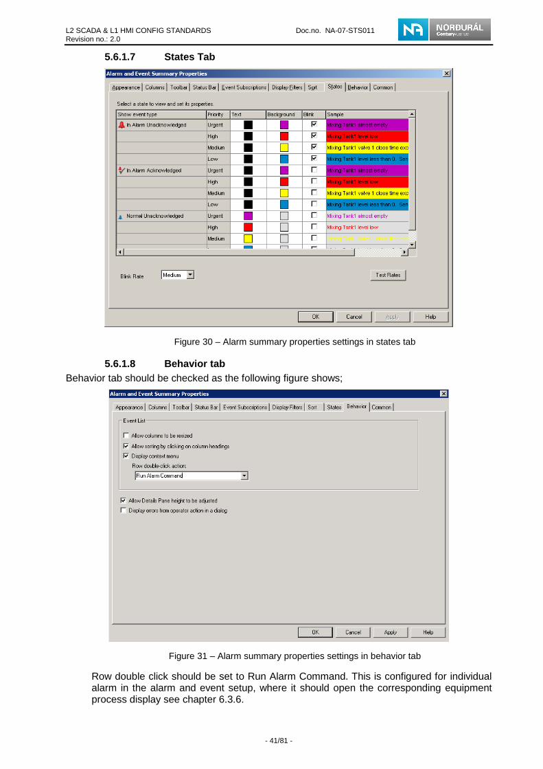
L2 SCADA & L1 HMI CONFIG STANDARDS Doc.no. NA-07-STS011 Revision no.: 2.0
- 41/81 -
5.6.1.7 States Tab
Figure 30 – Alarm summary properties settings in states tab
5.6.1.8 Behavior tab Behavior tab should be checked as the following figure shows;
Figure 31 – Alarm summary properties settings in behavior tab
Row double click should be set to Run Alarm Command. This is configured for individual alarm in the alarm and event setup, where it should open the corresponding equipment process display see chapter 6.3.6.

L2 SCADA & L1 HMI CONFIG STANDARDS Doc.no. NA-07-STS011 Revision no.: 2.0
- 42/81 -
Alarm Summary popup 5.7
The Alarm Summary popup displays current fault/alarm conditions (filtered by Alarm Class) and shall be configured as shown in pilot project. The Alarm Summary popup shall be accessed by a button in the ASN.
The Alarm summary popup should be configured the same way as the Main Alarm Summary.
Two screens are provided in this standard; one for user with acknowledges rights and one for read only access. The read only alarm summary doesn’t display acknowledge buttons and alarms cannot be acknowledged.
The Height of the popup is 280 pixel and width 1910 pixel.
Figure 32 – Alarm summary popup
5.7.1 Alarm Class filtering Alarm Class filtering is done by combination of HMI tag and VBA code. A HMI string memory Tag is created in the Tag Database for Alarm Filtering (in the pilot project is named AlarmFilters\AlarmClass. Alarms are created and have been categorized using Alarm Class where the Class is defined as the name of the process page where the equipment is visible on.
The Alarm Summary popup call button in the ASN writes the corresponding string (the name of the process page) in the mentioned HMI tag.
Example;
AlarmFilters\AlarmClass = "Motor"; Display GRT90_T370_Alarm_Summary_PopUp_Protected
A VBA code is called upon Animation Start for the Alarm Summary popup which reads the Alarm Filtering tag and constructs Filter definition string sent to the Alarm Event Summary object in the popup. No changes to this popup are allowed.
Changes on the Alarm Summary popup, HMI string and tag name are not allowed, this includes the VBA code.
Graphic Screen – View Types 5.8
Many types of views can be displayed in Zone 3.
• Overview
• Sub Overview
• Process Display screen (process display) equipment detail
• Popup (motor, valve, analog value trend etc.)
With the exception of the Overview level, the ASN zone shall always be present. Within the ASN zone, the ASN Control represents a specific sub area. Clicking the large button (line) at the top of each ASN Control displays a process display screen for the related Line/Process Overview level. Clicking each small button in the ASN Control shall display the related Unit Detail level.
5.8.1 Screen Navigation Hierarchy The screen hierarchy can include several levels the following figure is an overview of the Screen Navigation hierarchy.

L2 SCADA & L1 HMI CONFIG STANDARDS Doc.no. NA-07-STS011 Revision no.: 2.0
- 43/81 -
Figure 33 – Screen navigation hierarchy
5.8.2 Overview This view provides a view over entire area and all sub areas are accessible form this level. This level has buttons that can display a specific Sub Overview screen but they have no control or animation. It is allowed to implement a simple static descriptive image on these buttons.
Figure 34 – Overview page

L2 SCADA & L1 HMI CONFIG STANDARDS Doc.no. NA-07-STS011 Revision no.: 2.0
- 44/81 -
5.8.3 Sub Overview This view provides access to all lines/processes for the sub system. In this level ASN controls are available and also a buttons that provide access to the Line/Process Overview. Each button shall be linked to a specific Line/Process and the background of the button shall have a schematic view of the Line/Process. Buttons shall also display the status icons for faults or alarms that are present in the Line/Process. It is allowed to implement a simple static descriptive image on these buttons. This view does not allow equipment control.
Figure 35 – Sub overview page
Each button on this page corresponds to 1 process page and should call it upon release. A simple and none animated drawing should be present on each button for easier navigation. This drawing is usually the layout of the process page.
Alarm bell indicates the alarm state on each button for the group present on the process page. If there is more than 1 group present then alarm bell needs to be added accordingly.
Important: Only one sub overview display is allowed.
5.8.4 Process Display This view displays the Line/Process main page and/or Unit Detail level according to the use of the application. The process display screen contains static and dynamic objects, alarm information, and SFC statuses. The content of the process display screen may change but the shape, position, and size will not.
• Line/Process Level provides access to functionally related equipment groups. This level displays schematic views of the Line/Process in units with flow directions, Unit/Equipment states, and status. Single clicking on buttons provides more details along with access to the Unit Detail level.
o Unit Detail Level provides access to the Equipment Control level via a single click on an equipment object. A unit could be equipment or a group of equipment included in a line. In some cases, a Line/Process Flow button enables access to another Line/Process Overview screen within the same sub area. This level shall show equipment details, states, and statuses. Multiple Unit Detail levels may be necessary to fully represent a unit in a clear and precise manner.
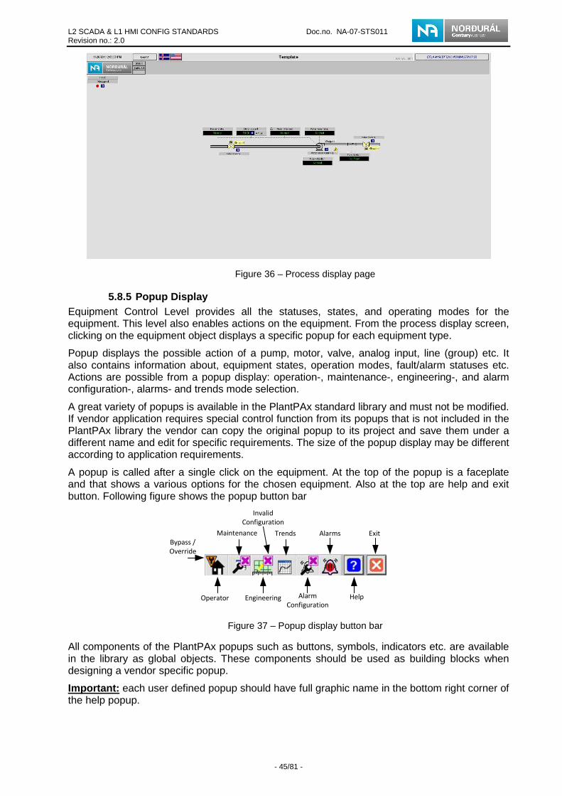
L2 SCADA & L1 HMI CONFIG STANDARDS Doc.no. NA-07-STS011 Revision no.: 2.0
- 45/81 -
Figure 36 – Process display page
5.8.5 Popup Display Equipment Control Level provides all the statuses, states, and operating modes for the equipment. This level also enables actions on the equipment. From the process display screen, clicking on the equipment object displays a specific popup for each equipment type.
Popup displays the possible action of a pump, motor, valve, analog input, line (group) etc. It also contains information about, equipment states, operation modes, fault/alarm statuses etc. Actions are possible from a popup display: operation-, maintenance-, engineering-, and alarm configuration-, alarms- and trends mode selection.
A great variety of popups is available in the PlantPAx standard library and must not be modified. If vendor application requires special control function from its popups that is not included in the PlantPAx library the vendor can copy the original popup to its project and save them under a different name and edit for specific requirements. The size of the popup display may be different according to application requirements.
A popup is called after a single click on the equipment. At the top of the popup is a faceplate and that shows a various options for the chosen equipment. Also at the top are help and exit button. Following figure shows the popup button bar
Operator
Maintenance
Engineering
Trends
Alarm
Configuration
Alarms
Help
Exit
Bypass /
Override
Invalid
Configuration
Figure 37 – Popup display button bar
All components of the PlantPAx popups such as buttons, symbols, indicators etc. are available in the library as global objects. These components should be used as building blocks when designing a vendor specific popup.
Important: each user defined popup should have full graphic name in the bottom right corner of the help popup.

L2 SCADA & L1 HMI CONFIG STANDARDS Doc.no. NA-07-STS011 Revision no.: 2.0
- 46/81 -
5.8.5.1 Faceplate Operator button The operator button will show day-to-day status of the chosen equipment. For example the operators view for an analog input (Figure 38) and motor (Figure 39) is:
Figure 38 – Popup display operator tab for an analog indicator
Figure 39 – Popup display operator tab for a motor
5.8.5.2 Faceplate Maintenance button This button is used by the maintenance group. This button shall be used to call a page that enables parameters adjustment and control interrupt for the equipment. In following examples are shown maintenance options for analog input (Figure 40) and motor (Figure 41):

L2 SCADA & L1 HMI CONFIG STANDARDS Doc.no. NA-07-STS011 Revision no.: 2.0
- 47/81 -
Figure 40 – Popup display maintenance tab for an analog indicator
Figure 41 – Popup display maintenance tab for a valve
5.8.5.3 Faceplate engineering button This button is for changing more detail control for the equipment and that control are variable between equipment. See the PlantPAx standard (Table)

L2 SCADA & L1 HMI CONFIG STANDARDS Doc.no. NA-07-STS011 Revision no.: 2.0
- 48/81 -
Figure 42 – Popup display engineering tab for a valve
5.8.5.4 Faceplate Trends button Some equipment have trends button. Trends show different information depending on which device is being handled. For example in Figure 43 is shown a trend window for analog input and the trend shows have the input change in time.
Figure 43 – Popup display trends tab for an analog indicator
5.8.5.5 Faceplate Alarm Configuration button In the Alarm Configuration button allows user to change severity, acknowledge requirements, restart requirements etc.

L2 SCADA & L1 HMI CONFIG STANDARDS Doc.no. NA-07-STS011 Revision no.: 2.0
- 49/81 -
Figure 44 – Popup display alarm configuration tab for an analog indicator
Changing severity of the alarms will only affect the way this alarm is presented in the object and/or how these alarms will affect the control of the equipment. These changes will not affect the alarm message in the alarm summary as those severity levels are fixed.
5.8.5.6 Faceplate Alarms button The Alarms button displays each alarm for the equipment which is being handled. See the PlantPAx standard Table 1.
Figure 45 – Popup display alarm tab for an analog indicator
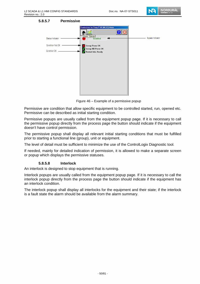
L2 SCADA & L1 HMI CONFIG STANDARDS Doc.no. NA-07-STS011 Revision no.: 2.0
- 50/81 -
5.8.5.7 Permissive
Figure 46 – Example of a permissive popup
Permissive are condition that allow specific equipment to be controlled started, run, opened etc. Permissive can be described as initial starting condition.
Permissive popups are usually called from the equipment popup page. If it is necessary to call the permissive popup directly from the process page the button should indicate if the equipment doesn’t have control permission.
The permissive popup shall display all relevant initial starting conditions that must be fulfilled prior to starting a functional line (group), unit or equipment.
The level of detail must be sufficient to minimize the use of the ControlLogix Diagnostic tool.
If needed, mainly for detailed indication of permission, it is allowed to make a separate screen or popup which displays the permissive statuses.
5.8.5.8 Interlock An interlock is designed to stop equipment that is running.
Interlock popups are usually called from the equipment popup page. If it is necessary to call the interlock popup directly from the process page the button should indicate if the equipment has an interlock condition.
The interlock popup shall display all interlocks for the equipment and their state; if the interlock is a fault state the alarm should be available from the alarm summary.

L2 SCADA & L1 HMI CONFIG STANDARDS Doc.no. NA-07-STS011 Revision no.: 2.0
- 51/81 -
Figure 47 – Example of an interlock popup
Graphic Screen – Static Object 5.9
Static objects are objects that do not change in response to input data (i.e. the object retains the same shape and color during run-time). In the process display screen, all critical equipment should resemble the actual shapes and sizes in proportion to each other as represented on the P&ID. The flow path of the material should be clearly visible.
In a multi-area and multi-programmer context, a unique pre-defined library of commonly encountered static objects shall be used to ensure uniformity and standardization of the operation for all areas. A project static object library shall be provided for use by all vendors. The objects dimensions can be modified only if the initial proportions are respected. These objects shall be described and listed in the vendors functional design specification. All user defined static objects will be verified in the FAT.
The following figure is an example of static objects in a process display screen:
Figure 48 – Process page static objects
The static objects are listed below:
(1) Static Element
(2) Static Text
(3) Process, Instrumentation and other Lines
1
2 3
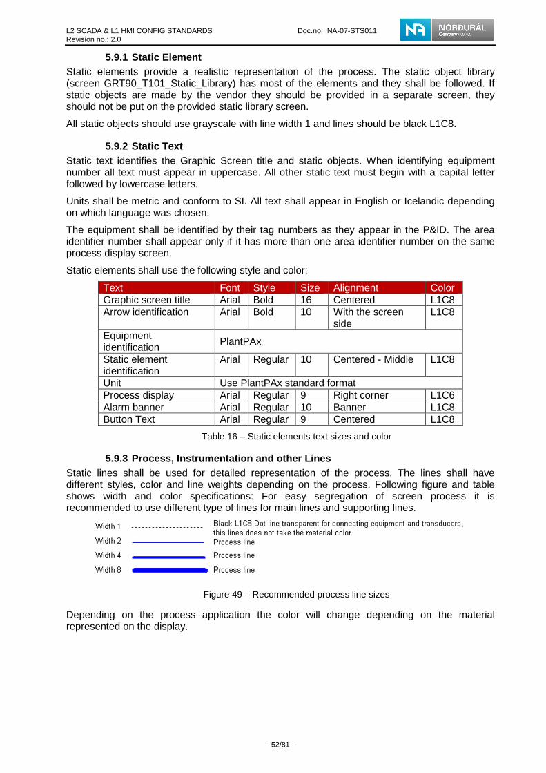
L2 SCADA & L1 HMI CONFIG STANDARDS Doc.no. NA-07-STS011 Revision no.: 2.0
- 52/81 -
5.9.1 Static Element Static elements provide a realistic representation of the process. The static object library (screen GRT90_T101_Static_Library) has most of the elements and they shall be followed. If static objects are made by the vendor they should be provided in a separate screen, they should not be put on the provided static library screen.
All static objects should use grayscale with line width 1 and lines should be black L1C8.
5.9.2 Static Text Static text identifies the Graphic Screen title and static objects. When identifying equipment number all text must appear in uppercase. All other static text must begin with a capital letter followed by lowercase letters.
Units shall be metric and conform to SI. All text shall appear in English or Icelandic depending on which language was chosen.
The equipment shall be identified by their tag numbers as they appear in the P&ID. The area identifier number shall appear only if it has more than one area identifier number on the same process display screen.
Static elements shall use the following style and color:
Text Font Style Size Alignment Color Graphic screen title Arial Bold 16 Centered L1C8 Arrow identification Arial Bold 10 With the screen
side L1C8
Equipment identification PlantPAx
Static element identification
Arial Regular 10 Centered - Middle L1C8
Unit Use PlantPAx standard format Process display Arial Regular 9 Right corner L1C6 Alarm banner Arial Regular 10 Banner L1C8 Button Text Arial Regular 9 Centered L1C8
Table 16 – Static elements text sizes and color
5.9.3 Process, Instrumentation and other Lines Static lines shall be used for detailed representation of the process. The lines shall have different styles, color and line weights depending on the process. Following figure and table shows width and color specifications: For easy segregation of screen process it is recommended to use different type of lines for main lines and supporting lines.
Figure 49 – Recommended process line sizes
Depending on the process application the color will change depending on the material represented on the display.

L2 SCADA & L1 HMI CONFIG STANDARDS Doc.no. NA-07-STS011 Revision no.: 2.0
- 53/81 -
Table 17 – Material color pallet
If process lines go form one process screen to another then there shall be a navigation button at the end of the line. This button shall provide navigation to the appropriate process screen where the line continues. Following figure shows the navigation button:
Figure 50 – Process line navigation arrows
Navigation button and the line shall always be in the same color. Navigation buttons are available in the pilot project.
Graphic Screen- Dynamic Object 5.10
A dynamic object is defined as an object associated with a specific data source. This object could be a button, touch area, or dynamic standard object.
A dynamic object library (screen GRT90_T100_Dynamic_Library) is provided with the pilot project.
For some specific conditions, the continuous animation could be used only to increase process understanding but the number of continuous animations must be minimized.
The Vendor can develop objects, the specific objects and the continuous animation must be defined in each sub area’s functional analysis. These objects are suspects for approval by Norðurál. If dynamic objects are made by the vendor they should be provided in a separate screen, they should not be put on the proved dynamic library screen.
Dynamic objects shall follow these rules:
• All analog values call a popup with the corresponding real-time trend (visual display of the time).
• When applicable objects shall be capable of changing their shape and position in response to changing bit point values. For example, a gate symbol will change

L2 SCADA & L1 HMI CONFIG STANDARDS Doc.no. NA-07-STS011 Revision no.: 2.0
- 54/81 -
according to the position of the gate. As point values change, the gate symbol moves to indicate the new position.
5.10.1 Equipment Dynamic Symbol The dynamic object symbol allow operators to see status of the equipment, with a single click get the corresponding popup and get a control over selected equipment. When a popup is used to control a dynamic object, a touch field must be placed under it.
All dynamic symbols which are provided in the PlantPAx standard (see Table 1) have similar design.
Figure 51 shows the dynamic symbol for single speed motor:
Figure 51 – Example of an equipment dynamic symbol
As shown in Figure 51 there are six symbols indications and they represents following:
• Config/Quality indicator:
Graphic Symbol Description
Invalid Configuration
I/O Fault (status is ”stale” or communication loss )
No symbol displayed I/O quality good and Configuration valid
Table 18 – Process page indication for status/quality
• Alarm indicator: If alarm occurs this indicator will appear (see Table 27)
• Label: Device name
• Mode indicator: The motor have seven modes as following
Graphic Symbol Description
The motor is in Hand (local) Mode
The motor is in Maintenance Mode
The motor is in Override Mode
The motor is locked in Program mode
The motor is in Program mode
The motor is locked in Operator Mode
The motor is locked in Operator Mode
No Mode: the instruction is scanned false and is out of service The outputs are held OFF and Alarms are not updated
The motor has been disabled
No symbol displayed The motor is in Program Mode
Table 19 – Process page indication for mode
• Maintenance Bypass indicator:
Not Rready indicator
Mode Indicator
Label Alarm indicator
Config/Quality indicator
Maintenance Bypass indicator
State indicator

L2 SCADA & L1 HMI CONFIG STANDARDS Doc.no. NA-07-STS011 Revision no.: 2.0
- 55/81 -
Graphic Symbol Description
A Maintenance Bypass is active
The motor is disabled
No symbol displayed No Maintenance Bypass active
Table 20 – Process page indication for maintenance bypass
• State indicator: The state indicator text changes and the graphic symbol color changes depending on the state of the motor.
Color State text Blue Stopping Gray Stopped Blue Starting Dark Green Running
Table 21 – Process page indication for state
5.10.2 Tank/Vessel Level Representation Tank and vessel objects shall not be dynamically filled. The bar graph object shall represent a tank/vessel level (PV value). The analog value must be represented in appropriate units for the Tank/Vessel etc. m3, ton, meter etc. and shall be located centered in the space between the vessel and the bar graph. If the mouse is moved over the object must appear a tooltip and when the user click on the PV value (level) a popup window will display.
Tooltip shall indicate the percentage (%) of fill when mouse pointer is over the level indicator.
The PV value must represent the appropriate unit for each tank/vessel, percentage (%), volume (m³), weight (kg or tons) etc.
The maximum volume (kg, m³ etc.) of the tank/vessel should be represented as a static text on the object as well as a description of the material the tank is used for. This should be the same as the PV unit.
Figure 52 – Tank/Vessel representation
5.10.3 Fault/Alarm Representation For equipment (motor, valve etc.) fault and alarm were dissociated from states representation (running, stopped etc.) to simplify the understanding of equipment functioning.

L2 SCADA & L1 HMI CONFIG STANDARDS Doc.no. NA-07-STS011 Revision no.: 2.0
- 56/81 -
The fault/alarm icons shall be used to show equipment or line (group) fault/alarm conditions. The icons shall be superposed and visible only when a fault/alarm condition occurs. If a fault/alarm occurs it shall be possible to push the equipment and navigate to the alarm popup.-Following figure shows fault/alarm for motor:
Figure 53 – Alarm representation in object and in equipment popup
All fault/alarm expressions can be found in the PlantPAx standard (Table 1) or pilot project and they shall be followed.
5.10.4 Multi-State Indicator This dynamic display field shall be used to indicate the status of the represented equipment or object.
The vendor is allowed to modify the multi-state indicators as he sees fit (dimension, text and color). These indicators should look like PlantPAx indicators. Texts should be descriptive for the state and should be kept to minimum. A multi-state indicator is provided in the pilot project as a reference.
The below example is of Ready/Not Ready multi-state indicator;
Figure 54 – Example of multi-state indicators
5.10.5 Digital input Indicator The digital input indicator is a standard objects provided with FTView SE. The digital input indicator is a string display object that enables displaying an input state, etc.

L2 SCADA & L1 HMI CONFIG STANDARDS Doc.no. NA-07-STS011 Revision no.: 2.0
- 57/81 -
Figure 55 – Digital input indicator
Further information about multi-state indicator can be found in the pilot project.
5.10.6 Analog Value Indicator and Data Entry The analog value indicator and data entry are standard objects provided with FTView SE. The analog value indicator is a numeric display object that enables displaying a tank level, equipment speed, etc.
Figure 56 – Analog value indicator
5.10.7 Position Indicator The position indicator represents the active position of equipment such as an elevator. The equipment current position shall be represented with the color green but grey for other inactive position. See the following example:
Figure 57 – Position indicator
State Color Code Normal Green L2C2 Inactive position Grey L1C4
Table 22 – Position indicator color pallet
5.10.8 Level indicator The level indicator represents the status of equipment such as a tank, etc. The indicator can show 2 states and they are following:
Position indicators
Dynamic arrow

L2 SCADA & L1 HMI CONFIG STANDARDS Doc.no. NA-07-STS011 Revision no.: 2.0
- 58/81 -
State Color Code High High & Low Low
Red L1C9
High & Low Yellow L2C1 Inactive position Grey L1C4
Table 23 – Level indication color pallet
Following figure shows example for a level indicator:
Figure 58 – Level indicator with limit alarms
Group control 5.11Group control interfaces are located in upper left corner on process screen when applicable. This interface is used to control group of equipment, units or sequences. It is not allowed to resize the group control object.
3
2
1
4 6
8
5 7
Figure 59 – Group control faceplate
1. Label: descriptive name of the group and/or subarea,
2. Alarm indicator.(See Table 27)

L2 SCADA & L1 HMI CONFIG STANDARDS Doc.no. NA-07-STS011 Revision no.: 2.0
- 59/81 -
3. Invalid configuration. (See Table 18)
4. Non-Recovarable Fault active
5. Group mode: Group can be in following mode:
Symbol Mode
Device in Maintenance mode
Device in Operator mode
Hand (Local)
Override
NO mode (out of service)
Alarm Inhibit (Suppressed or Disabled)
Communication failure (Stale)
A maintenance bypass is active
Table 24 – Group control modes
6. Recovable fault active
7. At Home Indicator – Green when machine is at Home – Else yellow
8. Bypass active
9. Status indicator: shows the status of the group.
Value State Border/Back Color
Caption Color
0 Unknown Purple L1C8 Black L1C8 1 Stopped Gray L1C4 Black L1C8 2 Stopping Blue L1C7 White L1C1 3 Starting Blue L1C7 White L1C1 4 Running Green L4C8 White L1C1 5 Comm. Failure Light
blue L5C3 White L1C1
6 Tripped Non Recoverable
L3C2 White L1C1
7 Tripped Recoverable L3C3 White L1C1 8 Homing L2C3 White L1C1 9 Hold Yellow L2C1 Black L1C8
Table 25 – Group control states
See Appendix B – Group Object for detailed description of the group indications.
Touch field is under the object which calls a group popup. From the popup the operator will be able to get information about the group and also control it. In the popup faceplate there are five tabs; Operator, Maintenance, Engineering, Alarm configuration and Alarm. Information about these tabs is available in chapter 4.6.4

L2 SCADA & L1 HMI CONFIG STANDARDS Doc.no. NA-07-STS011 Revision no.: 2.0
- 60/81 -
Figure 60 – Group control popup faceplate
The group is operated in the same manner as any equipment, and the faceplate has been constructed similar to the regular PlantPAx faceplate. The group control faceplate has two additional buttons the home- and hold buttons.
Symbol Description
Home
Hold
Table 26 – Group control extra buttons
Home button is used to get all the equipment in the group to the initial positions and pause button puts all equipment in the group in standby mode.
The home and hold buttons are only visible if the group has been configured for home and hold capability on the configuration tab.
The group control interface is available in pilot project and must not be changed.
Dynamic Object Configuration 5.12
There are two ways available to present objects in the SCADA system; use global objects or use object which use tag placeholders. The usage of global object is preferred.
5.12.1 Global objects The vendor should use the global objects provided in the pilot project as much as possible. Most of dynamic objects included in the standard library are global objects.
Global objects made by the vendor should be constructed in their own global objects page. These global objects are not allowed to be constructed in provided global object pages. Naming conventions can be seen in chapter 4.7 FTView Studio General Naming Convention
Global object parameters definitions have to be filled in with description.
It is desirable that PlantPAx objects are used as building blocks to construct new global objects.

L2 SCADA & L1 HMI CONFIG STANDARDS Doc.no. NA-07-STS011 Revision no.: 2.0
- 61/81 -
Tooltips 5.13
If the computer mouse is moved over an object a tooltip shall be visible with a short description of the functionality of the object. All PlantPAx objects have a tooltips window and they shall not be changed. Following figure shows example of a tooltip:
Figure 61 – Example of tooltips
Standard Buttons 5.14
The standard buttons are present on the graphic screens. They are used to open new pages or popup windows. In some cases, buttons have a color status. The standard button shall be used to call an equipment detail.
Sometimes a user does not have the option of clicking on a button for the following reasons:
• The user does not have the appropriate privileges
• The commands are not acceptable for the PLC sequence
When the user doesn’t have privileges to use a button the button needs to disabled and have a gray tone to it. The button should always be visible.
PID Button 5.15
The single loop PID button shall be displayed on process display screens. Multiple types of PID controllers are available in the RSLogix 5000 instruction library but not all have PlantPAx faceplates. The PIDE has aPlantPAx faceplate shown in this section.
It is preferred that the PlantPAx PID is used. If the vendor, by approval of Norðurál, wishes to design their own PID control (using other RSLogix 5000 function) they are allowed to do so. These controls are required to have the same look and design as the PlantPAx PID control and described in the functional design specifications.
Clicking the PID button, displays a popup that includes the following items:
• Control loop identification (name and description)
• Trend button (SP, PV and CV)
• Actual value of SP, PV and CV with engineering unit
• In manual mode, the controller output (CV) may be set by adjusting the set point (SP)
• Limits representation next to the set point (SP) bar graph
• Ability to change the SP and CV value
Following image shows the setup in more details:

L2 SCADA & L1 HMI CONFIG STANDARDS Doc.no. NA-07-STS011 Revision no.: 2.0
- 62/81 -
Figure 62 – PID popup home tab
Clicking on the maintenance button provides a popup for the PID Parameters.
Figure 63 – PID popup maintenance tab
Trends 5.16
Template for SCADA trends are available in the pilot project and all trends in Norðurál project shall respected the template.
Default settings for tends are following:
• Data sever is real-time data server
• Pen source should be set to historian server.
• Trend refresh Rate is 2 seconds

L2 SCADA & L1 HMI CONFIG STANDARDS Doc.no. NA-07-STS011 Revision no.: 2.0
- 63/81 -
• Maximum numbers of pens is eight
• Chart time range is 2 hours
• Display grid lines for X- and Y-axis is 4 for major and 0 for minor grid
• Following figure shows the runtime settings
Figure 64 – Trend configuration runtime tab settings
All other setting can Vendor change but with approval from owner.
All analog values or values shall be logged.
5.16.1.1 Trend features Trends features shall include the ability to move backward and forward within a selected time range, read the exact value of any variable by moving a sliding scale pointer on the graph or chart, and change the time scales by zooming in and out. A legend of the displayed tags is displayed at the bottom of the graph along with the values at the positions of the left and right sliding scale pointers.
Help page 5.17
The vendor has free design of this page. The page shall include vendors contact information. Vendor’s logo is allowed to be placed on this page. Links to plant documentation is required (for an example panel schematics and P&ID). These documents are shall be in PDF format.
Vendor should not integrate documents into the SCADA system, where document navigation is done within the SCADA system. Only links (or path) to these documents should be provided.
Documents should be stored locally or on Norðuráls network. Following is an example of directory path
C:\Documents\VendorsName\DocumentType
Where;
Documents This is always the first folder
VendorsName Name of the vendor who provides the system
DocumentType Should be short descriptive text (schematics, P&ID etc.)
Following figure is an example of help page layout;

L2 SCADA & L1 HMI CONFIG STANDARDS Doc.no. NA-07-STS011 Revision no.: 2.0
- 64/81 -
Figure 65 – Help page example
Sequence page 5.18
For each sequence there shall be a sequence screen implemented in the SCADA system. The sequence shall be visualized with sequence indicators included in the pilot project. Vendors are allowed to include step timers if they are descriptive for the sequence process flow. A legend shall be visible on this screen describing the functions of the sequence diagram.
Following figure is an example of a sequence screen layout with legend information;
Figure 66 – Sequence Screen Example
Screen List 5.19
This display provides access to the entire graphic screen included in a sub area. Only overviews, process and general full pages need to be listed. It is not necessary to list popups that are equipment depended.

L2 SCADA & L1 HMI CONFIG STANDARDS Doc.no. NA-07-STS011 Revision no.: 2.0
- 65/81 -
Figure 67 – Screen list
CLX Network Overview 5.20
This screen shall display the network including all ControlLogix controller statuses, Stratix switch statues, FactoryTalk Directory Server status, and Data Server and FTView Server status (server statuses are available by popup call) for a specific sub area. It shall be accessible with the Network button located on the Function bottom bar.
The remote rack shall not be represented on this screen. But, the Ethernet communication network switches must be represented.
The following information shall be represented for each ControlLogix controller:
• IP Address (AOI connected)
• Heartbeat (failure or normal condition)
• ControlLogix Controller date and time
• CPU status
• The CPU task statuses (running or inhibited)
Stratix switch information should be displayed and should the object call a detailed information popup.
Server statuses are available in a popup call from this page. These popup calls are conditional to how many servers are connected to the subarea. For sub area with 1-3 servers the popup GRT90_P200_ServerStatus should be used and for subareas with 4-6 servers the popup GRT90_P201_ServerStatusExtended should be used. These popup include VBA code which needs to be configured for the popup to work properly.
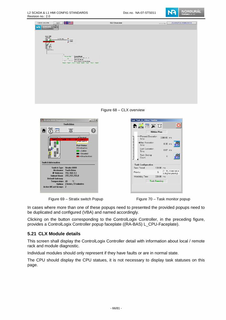
L2 SCADA & L1 HMI CONFIG STANDARDS Doc.no. NA-07-STS011 Revision no.: 2.0
- 66/81 -
Figure 68 – CLX overview
Figure 69 – Stratix switch Popup
Figure 70 – Task monitor popup
In cases where more than one of these popups need to presented the provided popups need to be duplicated and configured (VBA) and named accordingly.
Clicking on the button corresponding to the ControlLogix Controller, in the preceding figure, provides a ControlLogix Controller popup faceplate ((RA-BAS) L_CPU-Faceplate).
CLX Module details 5.21
This screen shall display the ControlLogix Controller detail with information about local / remote rack and module diagnostic.
Individual modules should only represent if they have faults or are in normal state.
The CPU should display the CPU statues, it is not necessary to display task statuses on this page.

L2 SCADA & L1 HMI CONFIG STANDARDS Doc.no. NA-07-STS011 Revision no.: 2.0
- 67/81 -
Figure 71 – CLX Module Detail
• The color used to represent the status of the different ControlLogix components shall be as follows for all screens:
• Failure: red color
• Normal Condition: green color
ALARM MANAGEMENT 6
Alarm states 6.1
Alarms have 6 main states and each state has a different priority. Following table show definition on each state. Blinking indicator means alarm has not been acknowledged.
State Definition Severity Color Urgent Communication and network fault 4
High Fault 3
Medium Warning 2
Low Info or prompt 1
Return to normal
Return to normal, but a previous Alarm has not been acknowledged
Inhibit Alarm has been inhibited
Table 27 – Alarm states and indication
Event / Message Definition 6.2
Events or messages are used for status information only, and do not require acknowledgement. An event is an informative event log for users. This type of message should be kept to a minimum.
Alarm Configuration 6.3
Alarm shall be defined and configured with the Alarm and Event setup. These alarms and descriptions shall be the same for the level 1 HMI client and the level 2 SCADA client screen.

L2 SCADA & L1 HMI CONFIG STANDARDS Doc.no. NA-07-STS011 Revision no.: 2.0
- 68/81 -
Each alarm must use a digital tag generated by the CLX Controller, analog alarms shall not be used.
All alarms shall be synchronized with information provided by the ControlLogix Controller using an Acknowledgment digital tag for each alarm, derived from a ControlLogix Controller tag. This Acknowledgment tag ensures alarms are acknowledged only once for each instance of an alarm.
The alarms are stored on the SCADA FTView Alarm and event server and in the central SQL database.
Setup instructions for the alarm and event server are given in the Rockwell automation documentation.
6.3.1 Alarm Severities Alarm severities shall be assigned to:
• Differentiate between urgent, high, medium, low, messages or events
• Determine how an alarm shall react when:
o It appears for the first time
o It is acknowledged
o It is cleared
There are four severity levels used as defined in the following table:
State Severity Range Use Low 1 0-250 Message
Medium 2 251-500 Warning high 3 501-750 Alarm
Urgent 4 751-1000 Control system faults Network and PLC. E-Stop
Table 28 – Alarm severity categorization
6.3.2 Alarm Definition The ControlLogix Vendor or the OEM shall provide an Excel spreadsheet that contains the following information for the alarm tag definitions and the PLC application code:
• ControlLogix Controller name
• Tag name
• Device Type
• UDT type
• Alarm type
• Alarm text
• Acknowledge tag
• Alarm severity
The alarm description text shall consist of a maximum of 80 characters.

L2 SCADA & L1 HMI CONFIG STANDARDS Doc.no. NA-07-STS011 Revision no.: 2.0
- 69/81 -
6.3.3 Alarm Class Definition Each alarm should have Alarm Class defined. Alarm Class should be set as the name of the process page where the equipment is visible. This is done for alarm filtering in the Alarm Summary popup (see chapter 5.7.1).
6.3.4 Current Alarm Format Current alarm related to a data is displayed in a single line format in the Alarm Summary screen. This screen is accessible from any graphic screen, using the Alarm button located on the Function bottom bar.
6.3.5 Alarm Management Alarm management is performed at level 1 by the ControlLogix Controller. Level 2 shall emulate the level 1. Clicking on the different acknowledgement buttons (Ack Current, Ack Page or Ack All) sends an acknowledgment request to the ControlLogix Controller. This causes the Alarm Acknowledgement bit to change to 1 inside the ControlLogix Controller. The ControlLogix Controller immediately changes the alarm bit to 0 if the fault/alarm condition has disappeared.
6.3.6 FactoryTalk View Command By double clicking a specific alarm in the Alarm and Event summary the display containing the faulty equipment should appear. The following is an example to call a motor process display from the alarm banner;
Display GRT80_S057_Conveyor
Diagnostic Log Configuration 6.4
The following instructions present the configuration restrictions for the diagnostic log:
• With the diagnostic setup utility, the directory for the diagnostic log files shall be the default directory C:\windows\system32\config\FTDiag.EVT.
• Log files older than ten (10) days shall be deleted when a new file is created.
Figure 72 – Diagnostic Log Configuration settings
STARTUP AND SECURITY 7Standard Windows server start-up and shutdown procedures shall be utilized.
SCADA Start-up 7.1
FTView SE clients must be configured for Windows 7 to start up without displaying the logon prompt. The Client shall then automatically launch the appropriate SE Client software.

L2 SCADA & L1 HMI CONFIG STANDARDS Doc.no. NA-07-STS011 Revision no.: 2.0
- 70/81 -
The client file should be called from the Windows startup folder, so the client will start as soon as the computer starts.
A description of this procedure is explained in the FTView SE User Manual.
7.1.1 Servers FTView servers on the Windows server shall use standard security; the servers shall be located in racks inaccessible to unauthorized personnel.
Security 7.2
Within an FTView application security restricts access to specific graphic screens.
The system shall transparently manage all security functions according to the following guidelines:
• User must enter an appropriate FactoryTalk user name and password to login into a client.
• A user shall not be able to select an unauthorized and protected item.
• Button, providing access to popup with commands, shall be visible only if the user has the appropriate security codes.
The security requirement of the application shall be defined in each functional analysis.
7.2.1 Security – Group and User Windows-linked accounts shall be used for the security management. Groups will be created in the windows domain in which windows users will be added.
Windows Groups will be added in the FactoryTalk Security. The access rights can then be associated to the group for the runtime security.
When a Windows-linked user attempts to access system resources, FactoryTalk Directory relies on Windows to determine whether the user’s name and password are valid, and whether the account is active or locked out.
7.2.2 FactoryTalk View SE Security – Service FactoryTalk Security Services :
• Used to create security accounts for users and groups, to set up general security permissions on common actions.
For the Norðurál Site, five (5) possible levels of user accounts can be configured. The different user levels, user names, and passwords shall be configured as one of the following possible types of system accounts:
• Read-only: Default startup mode. No one is logged in; screens are only available in read-only setup.
• Operator : Operator privileges shall have access to most of the day-to-day operating functions of the system.
• Supervisor . Change set points. Supervisor shall have access to all of the day-to-day operating functions of the system.
• Maintenance : Maintenance privileges include access to all levels that operator and supervisor have. Also have access to control bypass, feedback, override inputs, enable/disable device etc.
• Engineering : Shall have access to all levels of the system.

L2 SCADA & L1 HMI CONFIG STANDARDS Doc.no. NA-07-STS011 Revision no.: 2.0
- 71/81 -
In the “PlantPAx Process Library Security Configuration” document are more detailed information about system accounts and they shall be followed.
7.2.3 FactoryTalk View SE Security – Run time FactoryTalk View Runtime Security:
• Used to manage run-time security for HMI project components.
• Protects access to HMI project components by assigning security codes (A - P) to users and user groups (in the Runtime Security editor).
• Security Codes A to P can be assigned to user in FactoryTalk View SE Runtime Security editor. Following table shows what security codes each user level has: (In the “PlantPAx Process Library Security Configuration” document are more detailed information about security codes and they shall be followed.)
Security Code A B C D E F G H I J K L M N O P
Read-only Operator X X X X X Supervisor X X X X X X X X X Maintenance X X X X X X X X X X X Engineering X X X X X X X X X X X X X X X X
Table 29 – FactoryTalk View SE Security code
Figure 73 – FactoryTalk View SE Security users
Each protected object shall have Security Code corresponds to the PlantPAx standard library. Following image shows a security code for an object:

L2 SCADA & L1 HMI CONFIG STANDARDS Doc.no. NA-07-STS011 Revision no.: 2.0
- 72/81 -
Figure 74 – Current user function call
7.2.4 Login/Logout Login button is located in the top of each screen and is attached to a login popup as following figure shows.
Figure 75 – Login popup
When user logout all process screens, popups and protected elements shall be closed but current process screen shall reopen with the read-only user level access.
Auto logout shall activate at specific time every day governed by the shift change.
7.2.5 FactoryTalk Security - Structure for the Star t-up Phase A list of standard user names and passwords shall be issued by Norðurál to configure during project implementation.
FactoryTalk shall use the security structure shown in Figure 76 during the startup phase (before the network is completed).
During the start-up phase, the system will be configured in a workgroup. For workgroup installations operating system linked users and password names shall not be used – only direct FactoryTalk accounts.
Username Password Read-only Readonly readonly Operator Operator operator Supervisor Supervisor supervisor Maintenance maintenance maintenance Engineering Engineering engineering
Table 30 – Commissioning FT accounts

L2 SCADA & L1 HMI CONFIG STANDARDS Doc.no. NA-07-STS011 Revision no.: 2.0
- 73/81 -
Figure 76 – FactoryTalk Security workgroups
DeskLock 7.3
DeskLock is a FactoryTalk View tool for the Windows operating system. It is used to choose settings so that an operator using FactoryTalk View cannot gain access to functionality not expressly configured by the system integrator.
It also allows control to hide items on the Windows Explorer desktop, including the Taskbar and Start Menu, disable key combinations that are used to perform specific Windows actions such as accessing the Task Manager, and provides access to the Microsoft Management Console for more advanced configuration.
HMI LEVEL 1 INTERFACE 8This section contains the general structure of a HMI level 1 application. The PlantPAx library is available with faceplates for the FTView ME level 1 HMI systems and those faceplates are homogenous to the faceplates utilized in the SCADA system FTView SE.
Auto logout should be set to 30 minutes exception can be made with Norðurál approval.

L2 SCADA & L1 HMI CONFIG STANDARDS Doc.no. NA-07-STS011 Revision no.: 2.0
- 74/81 -
HMI Level 1 Navigation Philosophy 8.1
Figure 77 – HMI level 1
The above example is a process screen on a HMI level 1 client with the title bar and the main button bar:
Since the HMI panels varies in size and aspect the layout of the Zones 1 and 2 may change but the predefined buttons shall always be visible. Panel View Plus 1000 is the smallest type allowed for the Norðurál Site.
Mainly, the level 2 interface standards will be used to develop the level 1 screen. However the following points should be keep in mind during the development of HMI level 1:
• The main objectives of level 1 interface are to operate and debug equipment.
• Simple process screens are preferred on a L1 HMI since it will result in an easier operation environment.
• Since the HMI level 1 screen are touch screen devices, no command should be sent by pressing a graphical equipment object on the screen.
• The first form displayed is always the overview page.
• Popup form will be used.
• All popup are in the PlantPAx library
o The dimension of object provided in the dynamic library must not be modified.
• The following screen is not required:
o Network diagnostic
o Because of the small screen size and the large area required for a touch screen application, ASN shall not be used.
• All other level 2 interface development standards are applicable.

L2 SCADA & L1 HMI CONFIG STANDARDS Doc.no. NA-07-STS011 Revision no.: 2.0
- 75/81 -
Graphic Screen Format 8.2
8.2.1 Zone 1: Title Bar The title bar is a horizontal bar located at top of each page. It contains the following information that should always be visible:
• Plant and area name on the left
• The screen title in the center
• Date and time on the right
8.2.2 Zone 2: Main Button Bar The main button bar is a horizontal bar located below the title bar. It contains at least six (6) buttons that should always be there:
• Main Menu: Go to the main menu form. The main menu form is the first form displayed when the application starts. The Main menu has the same function as the sub overview in the L2.
• Login
• Screen List: List of all application screens for navigation.
• Alarm: Go to the alarm summary form when it is applicable.
o The Alarm button turns red when active alarms are present and flashes red when unacknowledged alarms are present.
• Alarm history
• The overview page only contains buttons intended to detail other pages.
• Extra buttons will also be available for free use customized according to the application usage
8.2.3 Zone 3: Process Page The process display screen represents the monitored process status or Operation Support screen. A process display screen may include menus, sub-menus, detailed application views, trend views, graphs, and any other graphics that represent the monitored process. The zone may contain control device symbols (i.e. line control button and statuses display) graphs, blocks of text, and other graphic objects.
The group control display shall always be located in the top left section of Zone 3, if applicable. If there is more than 1 group present on the process page a group control displays should be added, forming a row at the top. It is allowed to locate the Group control button close to a specific group if there is more than one group in a process display and it improves process readability and understanding.
Touch Screen Utilization 8.3
Some specific rules apply to the use of the HMI touch screens.
8.3.1 Minimum touch Area Size Graphical objects that can be touched on the screen must have a minimum size of 40 x 40 pixels.
Application Naming 8.4
The same naming standards shall be used for L1 HMI as are used for L2 SCADA. All spaces and dashes must be replaced by an underscore character.
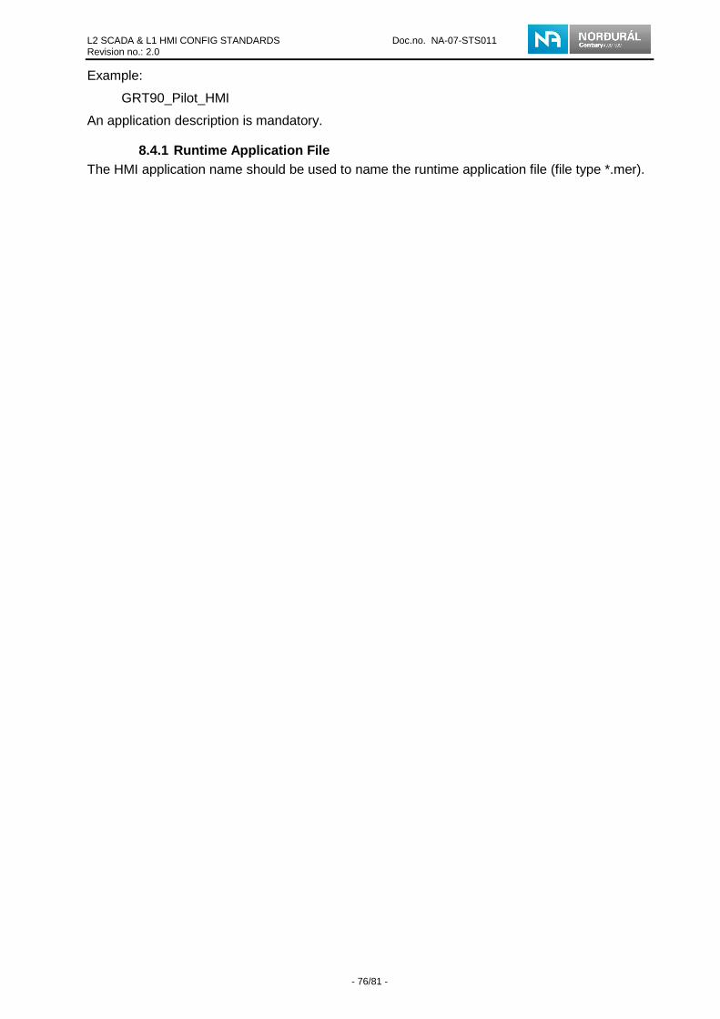
L2 SCADA & L1 HMI CONFIG STANDARDS Doc.no. NA-07-STS011 Revision no.: 2.0
- 76/81 -
Example:
GRT90_Pilot_HMI
An application description is mandatory.
8.4.1 Runtime Application File The HMI application name should be used to name the runtime application file (file type *.mer).

L2 SCADA & L1 HMI CONFIG STANDARDS Doc.no. NA-07-STS011 Revision no.: 2.0
- 77/81 -
Appendences 9
Appendix A – Plant System Architecture Levels 9.1
Figure 78 – Plant System Architecture Levels, large figure

L2 SCADA & L1 HMI CONFIG STANDARDS Doc.no. NA-07-STS011 Revision no.: 2.0
- 78/81 -
Appendix B – Group Object 9.2
The following table shows the value of the States tag for the Group AOI object and how different values are presented in the Group Object in the SCADA system
Value State indication ASN indication State Border Color Back Color Caption
Color
0
Unknown Purple L1C8 Purple L1C8 Black L1C8
1
Stopped Gray L1C4 Gray L1C4 Black L1C8
2
Stopping Blue L1C7 Blue L1C7 White L1C1
3
Starting Blue L1C7 Blue L1C7 White L1C1
4
Running Green L4C8 Green L4C8 White L1C1
5
Comm. Failure
Light Blue L5C3 Light
Blue L5C3 White L1C1
6
Tripped Non Recoverable L3C2 L3C2 White L1C1
7
Tripped Recoverable L3C3 L3C3 White L1C1
8
Homing L2C3 L2C3 White L1C1
9
Hold Yellow L2C1 Yellow L2C1 Black L1C8
Table 31 – Group states
The following table shows the value of the Val Notify tag for the Group AOI object and how different values are presented in the Group Object in the SCADA system.

L2 SCADA & L1 HMI CONFIG STANDARDS Doc.no. NA-07-STS011 Revision no.: 2.0
- 79/81 -
Value State indication ASN indication State Color Blink Color
0
No Alarms Gray L1C4
1
Out of alarm unack
Gray L1C4 White L1C1
2
Sev. 1 Light Blue L5C3
3
Sev. 1 unack
Light Blue L5C3 Gray L1C4
4
Sev. 2 Yellow L2C1
5
Sev. 2 unack Yellow L2C1 Gray L1C4
6
Sev. 3 Red L1C9
7
Sev. 3 unack Red L1C9 Gray L1C4
8
Sev. 4 Purple L5C8
9
Sev. 4 unack Purple L5C8 Gray L1C4
Table 32 – Group Val notify states

L2 SCADA & L1 HMI CONFIG STANDARDS Doc.no. NA-07-STS011 Revision no.: 2.0
- 80/81 -
Appendix C – Objects provided with the Pilot Proje ct 9.3
The following tables shows which objects are provided with the pilot project. These tables don’t show any PlantPAx screens, popups etc.
Graphic displayes name Description (EFLA) P_Group-Faceplate Group control popup (EFLA) P_Group-Help Group control help popup GRT00_S001_AreaOverview Overview example GRT90_P010_App_Abort Yes/No popup called when
application abort is requested GRT90_P200_ServerStatus Server status popup for 1
server GRT90_P201_ServerStatusExtended Server status popup for
redundant servers GRT90_P210_Stratix8000 Stratix switch popup GRT90_S001_SubOverview Sub Overview example GRT90_T001_Template Screen with layout of process
page GRT90_T100_Dynamic_Library Library of dynamic objects
(vendors should not add their dynamic objects here they should make their own dynamic library page)
GRT90_T101_Static_Library Library of static objects (vendors should not add their static objects here they should make their own static library page)
GRT90_T102_ColorPallete Library of usable colors GRT90_T103_Fonts Library of usable fonts GRT90_T200_ModelScreen Empty screen do used as a
template for process pages GRT90_T210_SequenceScreen Sequence screen example GRT90_T310_Screen_List Screen list example GRT90_T330_EmergencyStop Emergency Stop page
example (To be completed) GRT90_T340_Alarm_Summary Alarm summary to be
displayed with read-only access
GRT90_T350_Alarm_Summary_Protected Alarm summary to be displayed with login access
GRT90_T360_Alarm_Summary_PopUp Alarm summary popup to be displayed with read-only access
GRT90_T370_Alarm_Summary_PopUp_Protected Alarm summary popup to be displayed with login access
GRT90_T600_General_Trends General trend screen GRT90_X002_CLX_Overview CLX overview example GRT90_X003_CLX_ModuleDetail CLX module detail example GRT90_X010_Side_Panel Side panel example GRT90_X011_Bottom_Bar Bottom bar example GRT90_X100_HelpScreen Help screen example
Table 33 – Graphic displays provided with the pilot project
L2 SCADA & L1 HMI CONFIG STANDARDS Doc.no. NA-07-STS011 Revision no.: 2.0
- 81/81 -
Global object page Description (EFLA) Common Objects Objects (EFLA) Faceplate Objects Faceplate objects used in popup faceplates GRT90_X001_ASN_Template ASN and Header object for pages Stratix_8000_SE_v4 Stratix switch popup faceplate and objects
Table 34 – Global objects provided with the pilot project
Image name Description GRT90_NA_Logo Norðuál’s logo, to be used in the ASN GRT90_NA_Icelandic_Flag Icelandic flag to be used in the ASN, for language
switch GRT90_NA_USA_Flag USA flag to be used in the ASN, for language
switch
Table 35 – Images provided with the pilot project
Parameter file name Description GRT90_T100_ParameterFileExample Example of parameter file
structure
Table 36 – Parameter files provided with the pilot project