Embed Size (px)
DESCRIPTION
06472116
Citation preview

IEEE JOURNAL ON EMERGING AND SELECTED TOPICS IN CIRCUITS AND SYSTEMS, VOL. 3, NO. 1, MARCH 2013 13
An Energy-Efficient Sleep Scheduling With QoSConsideration in 3GPP LTE-Advanced
Networks for Internet of ThingsJia-Ming Liang, Member, IEEE, Jen-Jee Chen, Member, IEEE, Hung-Hsin Cheng, and Yu-Chee Tseng, Fellow, IEEE
Abstract—With the design of data communications in mind,3GPP LTE-advanced (LTE-A) is probably the most promisingtechnology for Internet of Things (IoT). For IoT applications,continuous low-rate streaming data may be reported from devicesover a long period of time, imposing stringent requirements onpower saving. To manage power consumption, 3GPP LTE-A hasdefined the discontinuous reception/transmission (DRX/DTX)mechanism to allow devices to turn off their radio interfaces andgo to sleep in various patterns. Existing literature has paid muchattention to evaluate the performance of DRX/DTX; however, howto tune DRX/DTX parameters to optimize energy cost is still leftopen. This paper addresses the DRX/DTX optimization, by askinghow to maximize the sleep periods of devices while guaranteetheir quality-of-service (QoS), especially on the aspects of trafficbit-rate, packet delay, and packet loss rate in IoT applications.Efficient schemes to optimize DRX/DTX parameters and scheduledevices’ packets with the base station are proposed. The key ideaof our schemes is to balance the impacts between QoS parametersand DRX/DTX configurations. Simulation results show that ourschemes can guarantee traffic bit-rate, packet delay, and packetloss rate while save energy of user equipments .
Index Terms—Discontinuous reception/transmission (DRX/DTX), internet of things (IoT), long term evolution-advanced(LTE-advanced), power saving, quality of service, sleep sched-uling.
I. INTRODUCTION
I NTERNET of THINGS (IoT) is a general idea to integratenumerous devices or machines with the Internet. For IoT
applications, such as video surveillance [1] and smart metering[2], devices need to report various events and streaming datato a central server over a long period of time in an efficientand robust way. Thus, the 3GPP LTE-advanced (LTE-A), whichis designed with wireless data communications in mind, is the
Manuscript received September 03, 2012; revised November 29, 2012;accepted December 14, 2012. Date of current version March 07, 2013.This work was co-sponsored in part by MoE ATU Plan, in part by the Na-tional Science Council (NSC) under Grant 100-2218-E-024-001-MY3, Grant98-2219-E-009-019, Grant 98-2219-E-009-005, and Grant 99-2218-E-009-005,in part by AS-102-TP-A06 of Academia Sinica, by Industrial TechnologyResearch Institute (ITRI), Taiwan, and in part by D-Link. This work was alsoconducted under the “AMI Enhancement Project” of III, which is subsidizedby MoEA. This paper was recommended by Guest Editor M. A. Bayoumi.J.-M. Liang, H.-H. Cheng, and Y.-C. Tseng are with the Department
of Computer Science, National Chiao-Tung University, Hsin-Chu 30010,Taiwan (e-mail: [email protected]; [email protected]; [email protected]).J.-J. Chen is with the Department of Electrical Engineering, National Univer-
sity of Tainan, Tainan 70005, Taiwan (e-mail: [email protected]).Digital Object Identifier 10.1109/JETCAS.2013.2243631
most promising technology for IoT applications. To accommo-date various streaming data of IoT applications, the LTE-A stan-dard has defined several quality-of-service (QoS) classes for dif-ferent traffic characteristics on the aspects of traffic bit-rate, tol-erable delay, and packet loss rate [3]–[5]. On the other hand,since IoT devices need to continuously report data over a longperiod of time, the requirements on power saving are more strin-gent. To save the energy of devices [also called user equip-ments (UEs)], the LTE-A standard has defined the discontin-uous reception/transmission (DRX/DTX) mechanism to allowdevices to turn off their radio interfaces and go to sleep whenno data needs to be received or transmitted from/to the basestation [also called evolved Node B (eNB)]. The key propertyof the DRX/DTX mechanism is to work in coordination withan eNB and its UEs and regulate UEs to wake up periodicallyto receive/transmit data from/to the eNB. Then, UEs can turnoff their wireless transceivers during the non-wake-up period tosave energy. Particularly, each UE adopts a specific timer to pro-long its wake-up period whenever it sees the data coming beforethe timer expires. Thus, some data posing unexpected delay canstill be received/transmitted after the regular wake-up periods.However, how to tune DRX/DTX parameters to minimize UEs’energy costs is still left as an open issue in LTE-A.In this paper, we address the DRX optimization problem1
with the consideration of UEs’ QoS requirements. The objec-tive is to maximize UEs’ sleep periods (i.e., non-wake-up pe-riods) to save their energy while satisfy their QoS requirementsin terms of traffic bit-rate, packet delay, and packet loss rate.We propose an efficient sleep scheduling scheme and a packetscheduling method to tackle this problem. The key idea of theseschemes is to balance the impacts between QoS parameters andDRX configurations.Major contributions of this paper are three-fold. First, this is
the first work to address the joint optimization on energy savingand QoS guarantee for IoT applications in the 3GPP LTE-A net-work. In addition to the generic traffic features, the extra packetdelay posed by IoT devices is also considered. Second, we de-velop an efficient sleep scheduling scheme to optimize the DRXmechanism which can fit all the packet delay probability modelsand effectively mitigate the packet loss issue and guarantee thetraffic bit-rate requirements of IoT applications. In addition, aDRX-aware packet scheduling scheme is also proposed to wellcooperate with the proposed sleep scheme to improve the perfor-mance on energy saving and QoS satisfaction. Extensive simu-lations show that our schemes can satisfy UEs’ QoSwhile incur-
1The DTX optimization problem is similar to the DRX problem.
2156-3357/$31.00 © 2013 IEEE
14 IEEE JOURNAL ON EMERGING AND SELECTED TOPICS IN CIRCUITS AND SYSTEMS, VOL. 3, NO. 1, MARCH 2013
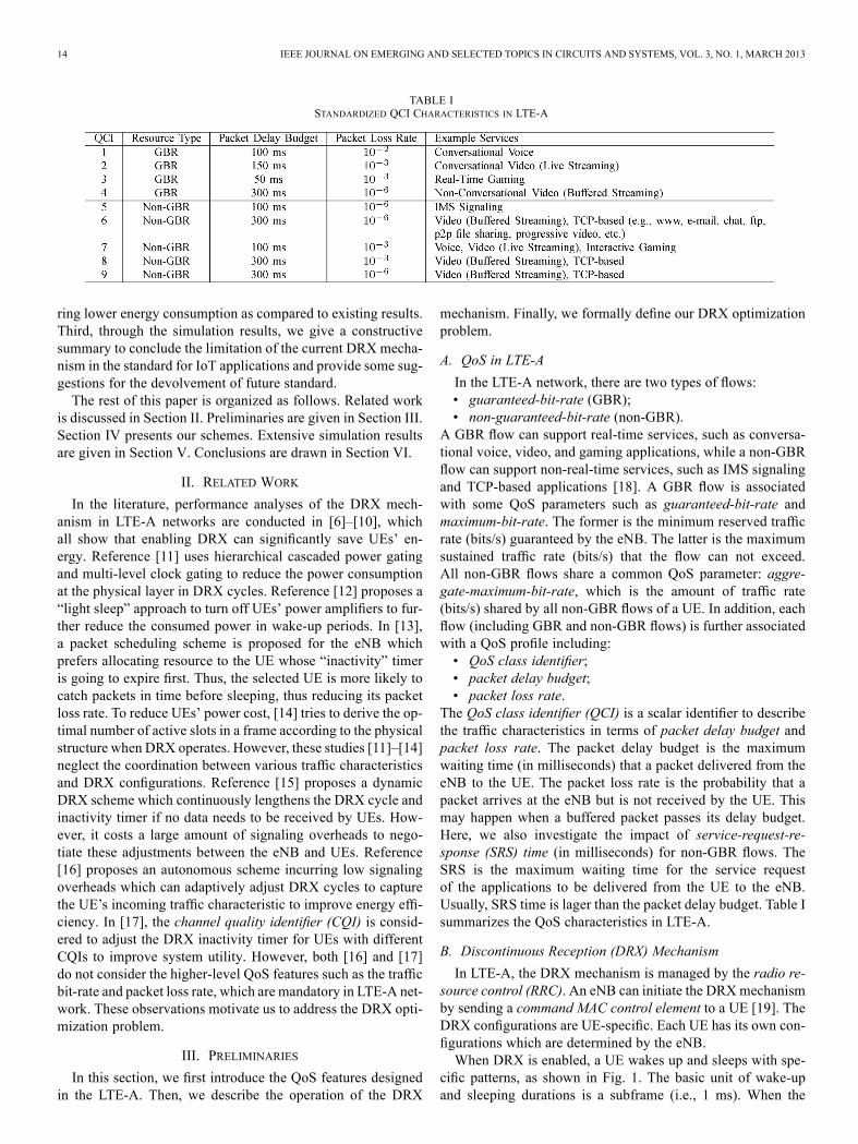
TABLE ISTANDARDIZED QCI CHARACTERISTICS IN LTE-A
ring lower energy consumption as compared to existing results.Third, through the simulation results, we give a constructivesummary to conclude the limitation of the current DRX mecha-nism in the standard for IoT applications and provide some sug-gestions for the devolvement of future standard.The rest of this paper is organized as follows. Related work
is discussed in Section II. Preliminaries are given in Section III.Section IV presents our schemes. Extensive simulation resultsare given in Section V. Conclusions are drawn in Section VI.
II. RELATED WORK
In the literature, performance analyses of the DRX mech-anism in LTE-A networks are conducted in [6]–[10], whichall show that enabling DRX can significantly save UEs’ en-ergy. Reference [11] uses hierarchical cascaded power gatingand multi-level clock gating to reduce the power consumptionat the physical layer in DRX cycles. Reference [12] proposes a“light sleep” approach to turn off UEs’ power amplifiers to fur-ther reduce the consumed power in wake-up periods. In [13],a packet scheduling scheme is proposed for the eNB whichprefers allocating resource to the UE whose “inactivity” timeris going to expire first. Thus, the selected UE is more likely tocatch packets in time before sleeping, thus reducing its packetloss rate. To reduce UEs’ power cost, [14] tries to derive the op-timal number of active slots in a frame according to the physicalstructure when DRX operates. However, these studies [11]–[14]neglect the coordination between various traffic characteristicsand DRX configurations. Reference [15] proposes a dynamicDRX scheme which continuously lengthens the DRX cycle andinactivity timer if no data needs to be received by UEs. How-ever, it costs a large amount of signaling overheads to nego-tiate these adjustments between the eNB and UEs. Reference[16] proposes an autonomous scheme incurring low signalingoverheads which can adaptively adjust DRX cycles to capturethe UE’s incoming traffic characteristic to improve energy effi-ciency. In [17], the channel quality identifier (CQI) is consid-ered to adjust the DRX inactivity timer for UEs with differentCQIs to improve system utility. However, both [16] and [17]do not consider the higher-level QoS features such as the trafficbit-rate and packet loss rate, which are mandatory in LTE-A net-work. These observations motivate us to address the DRX opti-mization problem.
III. PRELIMINARIES
In this section, we first introduce the QoS features designedin the LTE-A. Then, we describe the operation of the DRX
mechanism. Finally, we formally define our DRX optimizationproblem.
A. QoS in LTE-A
In the LTE-A network, there are two types of flows:• guaranteed-bit-rate (GBR);• non-guaranteed-bit-rate (non-GBR).
A GBR flow can support real-time services, such as conversa-tional voice, video, and gaming applications, while a non-GBRflow can support non-real-time services, such as IMS signalingand TCP-based applications [18]. A GBR flow is associatedwith some QoS parameters such as guaranteed-bit-rate andmaximum-bit-rate. The former is the minimum reserved trafficrate (bits/s) guaranteed by the eNB. The latter is the maximumsustained traffic rate (bits/s) that the flow can not exceed.All non-GBR flows share a common QoS parameter: aggre-gate-maximum-bit-rate, which is the amount of traffic rate(bits/s) shared by all non-GBR flows of a UE. In addition, eachflow (including GBR and non-GBR flows) is further associatedwith a QoS profile including:• QoS class identifier;• packet delay budget;• packet loss rate.
The QoS class identifier (QCI) is a scalar identifier to describethe traffic characteristics in terms of packet delay budget andpacket loss rate. The packet delay budget is the maximumwaiting time (in milliseconds) that a packet delivered from theeNB to the UE. The packet loss rate is the probability that apacket arrives at the eNB but is not received by the UE. Thismay happen when a buffered packet passes its delay budget.Here, we also investigate the impact of service-request-re-sponse (SRS) time (in milliseconds) for non-GBR flows. TheSRS is the maximum waiting time for the service requestof the applications to be delivered from the UE to the eNB.Usually, SRS time is lager than the packet delay budget. Table Isummarizes the QoS characteristics in LTE-A.
B. Discontinuous Reception (DRX) Mechanism
In LTE-A, the DRX mechanism is managed by the radio re-source control (RRC). An eNB can initiate the DRXmechanismby sending a command MAC control element to a UE [19]. TheDRX configurations are UE-specific. Each UE has its own con-figurations which are determined by the eNB.When DRX is enabled, a UE wakes up and sleeps with spe-
cific patterns, as shown in Fig. 1. The basic unit of wake-upand sleeping durations is a subframe (i.e., 1 ms). When the

LIANG et al.: AN ENERGY-EFFICIENT SLEEP SCHEDULING WITH QOS CONSIDERATION 15
Fig. 1. Overview of the DRX operation.
TABLE IISUMMARY OF THE DRX PARAMETERS
DRX mechanism is activated, there are six parameters to bespecified for each UE: 1) shortDRX-Cycle, 2) on-duration, 3)drxStartOffset, 4) drx-InactivityTimer, 5) longDRX-Cycle, and6) drxShortCycleTimer. The shortDRX-Cycle and longDRX-Cycle are the basic operation periods (in subframes) that the UEperforms wake-up and sleep operations. Usually, the length oflongDRX-Cycle is a multiple of the length of shortDRX-Cycle.The on-duration is an interval (in subframes) in a cycle thatthe UE has to stay awake. During the wake-up period, the UEwill monitor whether or not there is a physical downlink con-trol channel (PDCCH) delivered from the eNB to indicate anydownlink transmission to it. The drxStartOffset indicates thesubframe where the first on-duration starts. The drx-Inactivi-tyTimer is used for extending the wake-up period of the UEwhen finds any PDCCH delivered to it. Before drx-Inactivi-tyTimer expires, if the UE monitors a new PDCCH from theeNB, the drx-InactivityTimer resets and restarts to count downagain. Once the drx-InactivityTimer expires, the UE will startdrxShortCycleTimer and go to sleep (by turning off its inter-face). During the UE’s sleep period, all data for the UE willbe buffered in the eNB until the next on-duration comes. If noPDCCH is monitored by the UE during several shortDRX-Cy-cles, the drxShortCycleTimer will expire. Once the drxShortCy-cleTimer expires, the shortDRX-Cycle ends and the longDRX-Cycle follows. During the longDRX-Cycle, the UE behavessimilarly as it works in the shortDRX-Cycle. Once the UEmoni-tors the PDCCH, it terminates the longDRX-Cycle and starts theshortDRX-Cycle again. The DRX parameters are summarizedin Table II.We observe that the DRX configurations, QoS requirements,
and power constraints of a UE are tightly coupled with eachother. For example, a shorter shortDRX-Cycle can reduce aUE’s packet delay but decrease its sleep period. Also, a UE witha longer on-duration can enjoy a higher traffic bit-rate but it in-curs higher power cost to the UE. Further, a UE with a largerdrx-InactivityTimer can catch more packets to reduce the packetloss rate. However, it decreases the UE’s sleep periods. Finally,
a shorter longDRX-Cycle can reduce the SRS time of a UE butreduce its sleep period. Therefore, how to configure DRX pa-rameters is a critical problem.
C. The DRX Optimization Problem
We consider the downlink transmissions of an eNB servingUEs under time division duplex (TDD) mode2. Each
, has admitted GBR flows andnon-GBR flows, and each GBR flow has a guaranteed-bit-rate
(bits/s) and all non-GBR flows share an aggregate-max-imum-bit-rate (bits/s). For each flow (including GBRand non-GBR flows), it has a QoS profile in terms of packetdelay budget (ms) and allowable packet loss rate .The packet size of a flow may vary over time due to its IoTapplication. We assume that the packet size ranges fromto (bits/packet). The expected inter-arrival time of thepackets of flow is ms. In addition, each non-GBR flowhas a service-request-response time (ms) based on its IoTapplication, which is larger than its packet delay budget, i.e.,
. In this paper, we assume that each packet of flowof UE has a remaining packet delay budget whenbeing processed by our scheduler, where has a probabilitymass function . The extra delay of may be incurredby networks’ latency (in the case of downlink transmissions)or stream processing, compressing, coding, or packing latency(in the case of uplink transmissions). In each subframe, thebasic allocation unit for a UE is a resource block (RB). Supposethat there are RBs in a subframe. Note that the UE with ahigher channel quality can receive more data bits in a RB. Let(bits/RB) be UE ’s channel rate which may vary over time
and be measured during its wake-up period. We assume thatranges from to (bits/RB). The DRX optimizationproblem asks how to schedule resources and optimize theDRX parameters of each , including the on-duration ,drxStartOffset , shortDRX-cycle , longDRX-cycle
2The uplink transmissions are similar to the downlink ones.

16 IEEE JOURNAL ON EMERGING AND SELECTED TOPICS IN CIRCUITS AND SYSTEMS, VOL. 3, NO. 1, MARCH 2013
, drx-InactivityTimer , and drxShortCycleTimersuch that the QoS requirements of (i.e., , and
) can be met while the sum of sleep periods of all UEs canbe maximized.
IV. PROPOSED SCHEME
In this section, we present our three-stage (TS) scheme tothe DRX optimization problem. Once the parameters (i.e.,
) of each are determined, they willbe sent to each UE. On the other hand, a packet scheduling isproposed for the eNB to cooperate with UEs. Our TS schememaintains three key properties to reduce UEs’ wake-up periods.First, we make all ’s DRX cycle be an integer multipleof others’. This reduces UEs’ unnecessary wake-up periodsincurred by resource competition. Second, we also optimizethe drx-InactivityTimer (we use “InactivityTimer” for short)and help UEs to catch the packets posing unexpected delaysand thus to meet their delay budgets. Third, we allow UEs togo to “deep” sleep when their service-request-response timesare not violated. As the results, our scheme can save significantenergy and is quite suitable for IoT applications. The details ofthe scheme are described as follows.
A. Stage 1: Determining and
To decide of each , we first find thestrictest delay budget of each (denoted as )
(1)
Without loss of generality, let .Let . We determine , as follows:
(2)
Equation (2) implies that for all flow in be-cause . Since all flows’ packets of areserved with a cycle , this guarantees that all packets will meettheir delay budgets. Also note that (2) ensures to be an in-teger multiple of for . This can help UEs tointerleave their wake-up periods and avoid the competition forresources among UEs. Here, is the basic cycle and the allo-cation pattern will repeat after basic cycles due to ourarrangement (this will be clear later on).To decide of each , we first find the
strictest service-request-response time, denoted as , amongall non-GBR flows in
(3)
Since the size of longDRX-Cycle of should be an in-teger multiple of the size of its shortDRX-cycle , andmust be less than or equal to , we set , asfollows:
(4)
Note that (4) implies that for all non-GBRflow . Therefore, once a service request arrives in along cycle , it can guarantee the request to be served within
. Therefore, the service response time of all non-GBRflows in can be met.
B. Stage 2: Determining , and
To determine the on-duration of each ,we first calculate the sum of the maximum packet sizes of theflows in , whose delay budget is equal to its shortDRX-Cycle length , i.e., . Then, isset as follows:
(5)
We can see that by reserving subframes as ’s on-duration,the most urgent packet of flow is able to be served during theshortDRX-Cycle.Here, themost urgent packet is the packetwiththe delay budget equal to and arrives at the beginning of theshortDRX-Cycle. This packet has to be received by beforethe cycle ends; otherwise, it will be dropped. Note that (5) alsoimplies that uses the least numberofnecessarywake-up sub-frames by reserving necessary resource for urgent packets only,which can reduce the periodic wake-up periods of UEs.For determining the InactivityTimer of each
, we first model the expected packet loss rate, denotedby , for flow in by making use of its packet delayprobability . Then, a temporal InactivityTimer for eachflow is chosen to satisfy the flow’s packet loss rate. Finally, thebest InactivityTimer is determined for to meet all its flows’packet loss rate. The detail of the procedure is described as fol-lows.• Let be the number of packets of flow that should arriveduring ms (thus, ). Eachpacket may pose delay ms,
(we regard a packet to be lost if it is delayedover ms). Let be the subframe number that packetarrives to the eNB and can be served by the eNB. Withoutloss of generality, we regard the first subframe after ’sfirst on-duration ends as the subframe number 1. So wehave
(6)
where is the expected subframe number of the firstarrived packet of flow after ’s first on-duration endsand is the expected packet inter-arrival time of flow .Note that is the expected latencyfor serving a packet of flow through the network band-width shared by all UEs in the network, where
is the average numberof RBs to serve a packet of flow in and is theaverage number of available RBs that can allocate to thepacket per subframe defined by
(7)

LIANG et al.: AN ENERGY-EFFICIENT SLEEP SCHEDULING WITH QOS CONSIDERATION 17
Note that the first part of (7) is the average number of avail-able RBs per subframe for flow and is the ad-mitted bit-rate of flow
Then, the expected packet loss rate with the tem-poral InactivityTimer of flow in can be expressedas follows:
where and are the probability and thepacket loss ratio function of the packet delay distribution
such that
(9)
and
(10)
where
(11)
and
(12)
In (10), the denominator is the total number of arrivalpackets during the delay budget and the numerator is thenumber of packets failed to be received by due tothe expiration of InactivityTimer . In addition, [in(10) and (11)] is an indicator that returns 1 if the arrivalof packet can be received by ’s on-duration of thecycle; otherwise, it returns 0. Term [in (10) and (12)] isalso an indicator that returns 1 if the arrival of packet canbe received by the InactivityTimer; otherwise, it returns 0.Note that [in (11) and (12)] is used to evaluate thewaiting time if packet is received until the next on-du-ration of , i.e.,
. Term in (12) is the interval between thearrivals of packet and packet , where packet satisfies
and is successfully received by the on-duration orInactivityTimer of , i.e.,
(13)
Thus, it implies that once packet arrives at the subframenearby that of packet which is received successfully by
the UE’s on-duration or the InactivityTimer, the packetcan also be received by through the extended Inactiv-ityTimer triggered by packet .
• Then, we choose a temporal InactivityTimer to meetthe required packet loss rate of flow , i.e.,
(14)
Note that a shorter InactivityTimer can potentially re-duce the wake-up period of the UE when the requiredpacket loss rates are the same.
• Finally, the best InactivityTimer is chosen for soas to satisfy the packet loss rate of all the flows in :
(15)
Note that to speed up the calculation of the best Inactivi-tyTimer for UEs, we can use a larger unit (in mil-liseconds) for packet delay budget, InactivityTimer, andcycle length, thus the expected packet loss rate incurredby the temporal InactivityTimer can be rewritten as
. This can significantly reduce the computationalcost. In addition, because the best temporal Inactivity-Timers of the flows are the same if the flows are with thesame traffic characteristics (i.e., packet inter-arrival time,packets loss rate, packet delay budget, and packet delaydistribution), we can record these information and corre-sponding best InactivityTimers for further accelerating thecomputation.
For determining of each , we set% ,
where is the subframe number to trigger drxShortCycle-Timer. Here, depending on the applications behavior, if nopacket arrives over the maximal service request-time, i.e.,
, it has a higher probability thatthere will be no packet arrival later. This feature can be usedfor the UE to go to deep sleep for further conserving energy.
C. Stage 3: Determining
To determine of each , we first definethe “crowded” degree for each cycle. Then, we recursively as-sign each UE a less crowded cycle in which the UE starts itsDRX operation to avoid resource contention. Finally, for eachcycle, to mitigate the resource competition among UEs, we dis-perse these UEs by assigning different drxStartOffsets (we use“startoffsets” for short) in the cycle, thus reducing unnecessarywake-up periods of the UEs. The detail of the procedure is de-scribed as follows.• First, let be the first available subframe in each cycle
. Initially, set . Then, wedefine the “crowded” degree for cycle as the totalamount of the resident UEs’ least wake-up time, wherethe least wake-up time of in each shortDRX-Cycleis . Initially, set .
• Second, we recursively assign each a temporalstartoffset , which is composed of two parameters,
and , where is ’s resident cycle

18 IEEE JOURNAL ON EMERGING AND SELECTED TOPICS IN CIRCUITS AND SYSTEMS, VOL. 3, NO. 1, MARCH 2013
TABLE IIICHANNEL QUALITY IDENTIFIER (CQI) SUPPORTED IN LTE-A NETWORKS [20]
and is the startoffset in the th cycle, i.e.,. For , we
choose the cycle which is with the smallestamong the first cycle. Then, we give atemporal startoffset by assigning and
and update . For, we repeatedly update
dueto its cyclic feature. Finally, update for each of theseupdated cycles accordingly.
• Third, based on the results of previous step, we proportion-ally redistribute the drxStartOffset for each . First,we derive . Then, we as-sign each ’s according to the ratio suchthat .
D. Packet Scheduling at the eNB
At the eNB, we design a DRX-aware scheduling scheme tocooperate with the proposed TS scheme. This scheduler willkeep aware of UEs’ DRX operations and maintain a additionalvirtual queue for each UE to collect the packets which will bedue before its current cycle ends. Specifically, when allocatingdata in a subframe, the eNB will allocate stringent data first. Apacket is considered stringent if it is in the virtual queue and willbe dropped in the next subframe. Also, for those UEs whoseInactivityTimers will expire at the next subframe, our packetscheduler will allocate them one RB if their virtual queues arenot empty. Finally, the remaining RBs of the subframe will beallocated to the UEs with buffered data and are with higherchannel rate as compared to their average channel rates to im-prove transmission efficiency.
E. Time Complexity Analysis
We analyze the time complexity of the proposed TSscheme as follows. In the stage one, it coststo find the strictest delay for and coststo sort all UEs’ strictest delays. Then, to determine UEs’shortDRX-Cycle lengths costs . Similarly, it costs
to find the strictest SRS time for each . Then,to determine UEs’ longDRX-Cycle lengths costs .Let ) be the total number offlows in the network and thus the stage one totally costs
.In the stage two, to sum up the maximum packet size of ’s
flows costs . Thus, all UEs cost to determineall their on-duration lengths. Next, it costs
to calculate the expected packet loss rate for each flow be-cause flow has delay distributions, whereis the unit to speed up the calculation for expected packet lossrates and each distribution costs to calculate the value of
. Because the network has flows, each flow costsat most ) times to derive its expectedpacket loss rate to find the best InactivityTimer. Thus, all UEscosts to find their best Inactivi-tyTimers to satisfy their target packet loss rates. Finally, it costs
to determine the drxShortCycleTimer for all UEs. Thus,the stage two totally costs
.In the stage three, for each UE, it costs to
choose the least crowded cycle among cycles andcosts when updating the crowded degrees of allcycles. Since we have UEs, it costs todetermine the cycle where each UE starts its DRX operation.Finally, to proportionally redistribute UEs’ startoffsets over
cycles costs . Thus, the stagethree totally costs
).Therefore, the time complexity of the TS scheme incurred by
the three stages is. We should note that
the terms , and are very smallconstant values as compared to (i.e., , and
) and the total number of flows is usuallyconstant times of (i.e., ).On the other hand, for the proposed packet scheduling
scheme, it costs to find the stringent data amongflows, where each flow cumulates at most packets in eachsubframe. Next, it totally costs to allocate one RB to theUEs whose InactivityTimers will expire in the next subframe.Finally, it costs to sort UEs according to thedesignate priority. Thus, the DRX-aware scheduling schemetotally costsdue to and .
V. PERFORMANCE EVALUATION
In the section, we present our simulation results to verify theeffectiveness of the proposed scheme. We develop a simulatorin JAVA language. The system parameters of the simulator arelisted below. The frame duration is 10 ms. The channel band-width is 10 MHz. Thus, we have RBs in each sub-frame. Fifteen channel qualities are adopted in the simulation,as shown in Table III. Six types of applications are consideredin the simulation. The QoS parameters of these applicationsare shown in Table IV. We also consider three types of UEswhich adopt different applications. The first type of UEs adoptsonly one GBR flow. The second type of UEs adopts only onenon-GBR flow. The third type of UEs adopts both one GBR andone non-GBR flows. The number of these three types of UEs are

LIANG et al.: AN ENERGY-EFFICIENT SLEEP SCHEDULING WITH QOS CONSIDERATION 19
TABLE IVTRAFFIC ADOPTED IN THE SIMULATION [21]–[24]
the same. The packet delay is modeled by the normal distribu-tion with a mean of 0 and a standard deviation of 0.2 times of aflow’s delay budget. The channel quality of each UE will varyover time. We generate the channel condition randomly in eachsubframe for each UE from Table III. Note that the unit to cal-culate the InactivityTimer for our scheme is and the basiccycle is .We compare our scheme against the Counter-Driven DRX
(CDD) scheme [16] and the Multiple-Threshold DRX (MTD)scheme [17], which are the most relative schemes to the topicof this paper. The rationale of CDD scheme is to dynamicallyadjust each UE’s cycle length to capture the UE’s incomingtraffic to improve energy efficiency and data receiving latency.The rationale of MTD scheme is to dynamically adjust eachUE’s InactivityTimer to accommodate different CQIs that theUE perceives to maintain energy efficiency while increasing thetraffic rate satisfaction. Specifically, the CDD scheme adjustseach UE’s cycle length based on two predefined counters andtwo thresholds. Thus, if the UE consecutively wakes up but doesnot receive the data delivered from the eNB, the first counter ofthe UE is increased. Otherwise, the UE resets its first counter.Once the UE’s first counter reaches the predefined threshold
, the UE enlarges its cycle length to improve its sleep ef-ficiency because the incoming traffic for the UE seems sparse.Contrarily, if the UE consecutively wakes up and receives thedata from the eNB, the second counter of the UE is increased.Otherwise, the UE resets its second counter. Once the secondcounter reaches the predefined threshold , the UE decreasesits cycle length to reduce the packet receiving latency. Note thatin the simulation we choose and forCDD, which is recommended in [16] for the best performanceon energy saving and packet receiving latency. On the otherhand, theMTD scheme fixes each UE’s cycle length and adjuststheir InactivityTimers based on the predefined SINR-thresholdsfor the channel quality identifier (CQI) that they perceive. If theUE’s SINR is persistently smaller than the low SINR-thresholdof the CQI that it perceives, the UE’s InactivityTimer length willbe increased because the UE has a lower CQI which needs moretime to receive the incoming data. This can improve the UE’srate satisfaction. Contrarily, once the UE’s SINR is persistentlyhigher than the high SINR-threshold of the CQI that it perceives,the UE’s InactivityTimer length will be decreased because theUE has a higher CQI which needs less time to receive the in-coming data. This can improve the UE’s sleep efficiency.We consider two scenarios with different types of traffic:
general traffic (SN1) and IoT traffic (SN2). The general traffic,which requires higher data rate, includes VoIP (G.711), IPTV
Fig. 2. Impact of number of UEs on packet loss rate in scenarios SN1 and SN2.(a) SN1 (general traffic). (b) SN2 (IoT traffic).
(H.264), and HTTP/FTP services. The IoT traffic, whichrequires lower data rate, includes the applications for audiosurveillance (AMR), video surveillance (QVGA), and smartmetering. In the following results, the duration of each experi-ment is at least 6000 subframes.
A. Packet Loss Rate
We first compare the average packet loss rate under differentnumbers of UEs. Fig. 2(a) and (b) shows the results for SN1 andSN2, respectively. In both Fig. 2(a) and (b), we can see that thepacket loss rate of most schemes increases when the number ofUEs increases. This is because the network is getting saturatedand it becomes difficult to serve all UEs’ packets under the con-sideration of packet delay budgets. TheCDD scheme incurs thehighest packet loss rate because it only adjusts DRX cycles forUEs but neglects to tune their InactivityTimers. Once the UE’spacket delay budget is used up at the middle of its cycle, theUE will fail to receive the packet. On the other hand, theMTDscheme has the lower packet loss rate because the UEs can ad-just their InactivityTimers when they are under different channelconditions. It is important to note that our scheme outperformsother schemes. The packet loss rate of our scheme is even lowerthan when the network is saturated (i.e., 400 UEs in SN1and 1000 UEs in SN2). This is because our scheme can optimizeUEs’ InactivityTimers according to their target packet loss ratesand cooperate with the DRX-aware scheduling to serve the ur-gent data first to fully utilize the resource. Thus, the packet lossrates of UEs can be exactly guaranteed.
B. Jitter
We then measure jitter under different numbers of UEs,where jitter is defined as the standard deviation of packetdelivery latency [25]. Fig. 3(a) and (b) shows the results forSN1 and SN2, respectively. In Fig. 3(a) and (b), the CDDscheme and MTD scheme have higher jitter because CDD

20 IEEE JOURNAL ON EMERGING AND SELECTED TOPICS IN CIRCUITS AND SYSTEMS, VOL. 3, NO. 1, MARCH 2013
Fig. 3. Impact of number of UEs on jitter in scenarios SN1 and SN2. (a) SN1(general traffic). (b) SN2 (IoT traffic).
Fig. 4. Impact of number of UEs on rate satisfaction ratio of UEs in scenariosSN1 and SN2. (a) SN1 (general traffic). (b) SN2 (IoT traffic).
increases UE’s cycle lengths if UEs do not receive their packets(due to dropped) and MTD assigns InactivityTimers for UEsdisregarding the network traffic load, thus the buffered packetshave to wait until the next on-duration comes, which resultsin longer delivery latency. We should note that our schemeoutperforms other schemes in most cases. This is because ourscheme can optimize the InactivityTimers by giving longer In-activityTimers for UEs when the network traffic load becomesheavy. Thus, the UEs can receive the target packets earlier, ascompared to other schemes.
C. Rate Satisfaction Ratio
Next, we investigate the average rate satisfaction ratio ofUEs, which is defined by the amount of satisfied rate (includingGBR and non-GBR flows in the UE) over the total amountof admitted rates of UEs. When the satisfaction ratio is 1, itmeans that the scheme can successfully satisfy the requiredrate of UEs. Fig. 4(a) and (b) shows the results for SN1 andSN2, respectively. As can be seen, all schemes have a ratesatisfaction ratio of 1 when the number of UEs is less than 40in SN1 and 200 in SN2, respectively, because the network isunder nonsaturated. The CDD scheme incurs the lowest ratesatisfaction when the number of UEs is larger than 80 in SN1and 300 in SN2, respectively, because this scheme loses lotsof packets, especially for those time-aware surveillance data,which will not be retransmitted. On the other hand, the MTDscheme has better rate satisfaction because the MTD schemeassigns InactivityTimers for UEs based their CQI and thusthe UEs can receive more packets even if they stay in a badchannel condition. We should note that our scheme performsthe best. The satisfaction ratio of our scheme is still 1 when thenumber of UEs is 400 in SN1 and 1000 in SN2, respectively.This is because our scheme can optimize DRX parameters in
Fig. 5. Impact of number of UEs on sleep ratio in scenarios SN1 and SN2. (a)SN1 (general traffic). (b) SN2 (IoT traffic).
Fig. 6. Power consumption model for UEs [26].
terms of cycle length and InactivityTimer based on the networktraffic load, and cooperates with a DRX-aware scheduler toserve the UEs with high channel quality to improve their ratesatisfactions.
D. Average Sleep Ratio
We then evaluate the average sleep ratio under different num-bers of UEs. Fig. 5(a) and (b) shows the results for SN1 and SN2,respectively. As shown in Fig. 5(a) and (b), the sleep ratio of ourscheme decreases when the number of UEs grows, because ourscheme extends UEs’ wake-up periods to guarantee their QoSwhen the network traffic load becomes heavy. Contrarily, thesleep ratio of the CDD scheme increases when number of UEsincreases. This is becauseCDD neglects the UEs’ QoS satisfac-tion. Note that theMTD scheme has a lowest sleep ratio becausethis scheme adjusts InactivityTimers of UEs only based on UEs’CQI which is independent with the network traffic load (i.e., thenumber of UEs).
E. Power Consumption
Consequently, we measure the average power consumptionof all schemes under different numbers of UEs, where the UE’spower consumption is modeled according to [26] and illustratedin Fig. 6. Fig. 7(a) and (b) shows the results for SN1 and SN2,respectively. As can be seen, the power consumption of ourscheme increases when the number of UEs increases. This isbecause UEs need more wake-up time to receive their data toguarantee their QoS when the network resource is insufficient.On the other hand, the power consumption of the CDD schemedecreases when the number of UEs increases, because the UEsenlarge their cycle lengths without considering QoS. Finally, thepower consumption of the MTD scheme is stable because this

LIANG et al.: AN ENERGY-EFFICIENT SLEEP SCHEDULING WITH QOS CONSIDERATION 21
Fig. 7. Impact of number of UEs on power consumption in scenarios SN1 andSN2. (a) SN1 (general traffic). (b) SN2 (IoT traffic).
TABLE VTRAFFIC ADOPTED FOR OBSERVATIONS
scheme adjusts InactivityTimers of UEs independent with thenetwork traffic load.
F. Observations on Sleep Ratio of UEs With Multiple Flows
Wenow investigate the impact of the flowswith different QoSparameters in the same UE on the sleep ratio performance. Thisis conducted especially for IoT scenarios because an IoT devicemay report different data via different flows according to dif-ferent applications such as audio and video surveillance. In thisobservation, we consider five types of UEs and each UE adoptstwo flows with different QoS parameters listed in Table V. Inparticular, the type-1, type-2, and type-3 UEs have the flowswith different packet delay budgets (i.e., 100 and 300 ms) butwith the same packet loss rate (i.e., ). The type-4 and type-5UEs have different packet loss rate (i.e., and ) butwith the same packet delay budgets (i.e., 100 ms). We conductthe observation through the proposed scheme to guarantee UEs’QoS. Fig. 8 shows the sleep ratio results of all types of UEs. Wecan see that type-3 UEs have the highest sleep ratio becausetheir flows have looser QoS constraints (i.e., a larger packetdelay budget and a higher required packet loss rate). Next, thesleep ratio of type-2 UEs is slightly lower than that of type-3UEs because each type-2 UE has one flow with a shorter packetdelay constraint. Then, the sleep ratio of type-1 UEs is lowerthan that of type-2 UEs because all of type-1 UEs’ flows havelower packet delay budgets. We should note that the sleep ratioof type-2 UEs is close to that of type-1 UEs but not close totype-3 UEs’, because the DRX mechanism enforces each UEto have only one cycle length and thus all flows of each UE arewith a common cycle length limited by the strictest delay budgetof the UE (i.e., 100 ms in this case). Thus, if the UE has a flowwith a higher delay budget, it can not have a longer sleep perioddue to the limitation. Consequently, we can see that the sleep ra-tios of type-4 and type-5 UEs are lower than that of type-1 UEs
Fig. 8. Impact of flows with different QoS in the UE on sleep ratio perfor-mance.
because they require stricter packet loss rate (i.e., ). Notethat the sleep ratio of type-4 UEs is close to that of type-5 UEsbecause the DRX mechanism enforces each UE to have a fixedInactivityTimer and thus all flows in the UE are with a commonInactivityTimer limited by the strictest packet loss rate of theUE (i.e., in this case). This strongly hurts the performanceon energy saving because the UEs have to adopt the longest In-activityTimer of their flows even if it has completed to receivethe packet of such flows.Based on above experiments and observations, we could sum-
marize the limitations of the current DRX mechanism as fol-lows. First, the current DRX supports only single cycle lengthand single InactivityTimer. Once the UE has the flows with dif-ferent delay budgets, the UE has to wake up in each cycle evenif the UE has received the packets completely in previous cy-cles. In addition, during the wake-up period, the UE has to waitfor the timer expiring even if it has no data to receive. Second,the DRX mechanism enforces each UE to wake up and sleeponly one period during a cycle. Thus, if the next data arrival ofthe UEs is far from the previous data arrival, the UE has to keepawake until the next data arrives. Above limitations would harmthe performance on power saving. For future IoT applications,we may suggest the standard to support multiple cycle lengthsand multiple wake-up/sleep patterns for each UE. Thus, the UEhas the flows with different delay budgets that can be modeledby multiple sleep patterns which can best fit the traffic charac-teristic in the UE. So, the UE can wake up according to thesepatterns precisely. In addition, a special indicator is expectedfor the eNB to notify UEs to go to sleep immediately. This canreduce the idle wake-up period caused by waiting for Inactivi-tyTimer expiring. By above suggestions, we think it can makeUEs’ sleep behaviors more flexible and more efficient.
VI. CONCLUSION
In this paper, we addressed the DRX optimization problemwhich considers the QoS requirements of IoT applicationsin LTE-A networks. An efficient three-stage scheme and aDRX-aware packet scheduling method are proposed to tacklethe problem. By balancing the impacts between QoS parame-ters and DRX configurations, simulation results have verifiedour schemes. It has shown that our schemes can fully guaranteeUEs’ QoS requirements in terms of packet loss rate, packetdelay, and traffic bit-rate while saving considerable power

22 IEEE JOURNAL ON EMERGING AND SELECTED TOPICS IN CIRCUITS AND SYSTEMS, VOL. 3, NO. 1, MARCH 2013
consumption of UEs. For future work, we will investigate theperformance bounds of the standard. In addition, the flexibleDRX schemes will also be studied.
REFERENCES
[1] L. Atzori, A. Iera, and G. Morabito, “The internet of things: A survey,”Comput. Netw. vol. 54, no. 4, pp. 2787–2805, 2010.
[2] D. Guinard, V. Trifa, S. Karnouskos, P. Spiess, and D. Savio, “Inter-acting with the SOA-Based Internet of Things: Discovery, query, se-lection, and on-demand provisioning of web services,” IEEE Trans.Services Comput. vol. 3, no. 3, pp. 223–235, Jul./Sep. 2010.
[3] General packet radio service (GPRS) enhancements for E-UTRAN ac-cess Mar. 2012, 3GPP TS 23.401, v11.1.0 (Release 11).
[4] Policy and charging control architecture Mar. 2012, 3GPP TS 36.213,v11.5.0 (Release 11).
[5] E-UTRAN; S1 application protocol (S1AP) Mar. 2012, 3GPP TS36.413, v10.3.0 (Release 10).
[6] L. Zhou, H. Xu, H. Tian, Y. Gao, L. Du, and L. Chen, “Performanceanalysis of power saving mechanism with adjustable DRX cycles in3GPP LTE,” in IEEE Veh. Technol. Conf., Sep. 2008, pp. 1–5.
[7] C. S. Bontu and E. Illidge, “DRXmechanism for power saving in LTE,”IEEE Commun. Mag. vol. 47, no. 6, pp. 48–55, Jun. 2009.
[8] J. Wigard, T. Kolding, L. Dalsgaard, and C. Coletti, “On the user per-formance of LTE UE power savings schemes with discontinuous re-ception in LTE,” in IEEE Int. Conf. Commun. Workshops, 2009, pp.1–5.
[9] K. Aho, T. Henttonen, J. Puttonen, L. Dalsgaard, and T. Ristaniemi,“User equipment energy efficiency versus LTE network performance,”Int. J. Adv. Telecommun. vol. 3, no. 4, pp. 140–151, 2010.
[10] S. Jin and D. Qiao, “Numerical analysis of the power saving in 3GPPLTE advanced wireless networks,” IEEE Trans. Veh. Technol. vol. 61,no. 4, pp. 1779–1785, May 2012.
[11] G. S. Kim, Y. H. Je, and S. Kim, “An adjustable power management foroptimal power saving in LTE terminal baseband modem,” IEEE Trans.Consumer Electron. vol. 55, no. 4, pp. 1847–1853, Nov. 2009.
[12] K.-C. Ting, H.-C.Wang, C.-C. Tseng, and F.-C. Kuo, “Energy-efficientDRX scheduling for QoS traffic in LTE networks,” in IEEE Int. Symp.Parallel Distributed Process. Appl., 2011, pp. 213–218.
[13] B. Huang, H. Tian, L. Chen, and J. Zhu, “DRX-aware schedulingmethod for delay-sensitive traffic,” IEEE Commun. Lett. vol. 14, no.12, pp. 1113–1115, Dec. 2010.
[14] R. Wang, J. S. Thompson, and H. Haas, “A novel time-domain sleepmode design for energy-efficient LTE,” in Int. Symp. Commun., ControlSignal Process., 2010, pp. 1–4.
[15] H. Xu, H. Tian, B. Huang, and P. Zhang, “An improved dynamic userequipment power saving mechanism for LTE system and performanceanalysis,” Sci. China Inf. Sci. vol. 53, no. 10, pp. 2075–2086, 2010.
[16] E. Liu, J. Zhang, and W. Ren, “Adaptive DRX scheme for beyond 3Gmobile handsets,” in IEEE Global Telecommun. Conf., Dec. 2011, pp.1–5.
[17] S. Gao, H. Tian, J. Zhu, and L. Chen, “A more power-efficient adaptivediscontinuous reception mechanism in LTE,” in IEEE Veh. Technol.Conf., Sep. 2011, pp. 1–5.
[18] M. Alasti, B. Neekzad, J. Hui, and R. Vannithamby, “Quality of servicein WiMAX and LTE networks,” IEEE Commun. Mag. vol. 48, no. 5,pp. 104–111, May 2010.
[19] E-UTRA; Medium access control (MAC) protocol specification Mar.2012, 3GPP TS 36.321, v10.5.0 (Release 10).
[20] E-UTRA; Physical layer procedures Jun. 2012, 3GPP TS 36.213,v10.6.0 (Release 10).
[21] R. Mehmooda, R. Alturkia, and S. Zeadally, “Multimedia applicationsover metropolitan area networks (MANs),” J. Netw. Comput. Appl. vol.34, no. 5, pp. 1518–1529, 2010.
[22] G. Gualdi, A. Prati, and R. Cucchiara, “Performance comparison ofcontrol-less scheduling policies for VoIP in LTEUL,” in IEEEWirelessCommun. Netw. Conf., 2008, pp. 2497–2501.
[23] G. Gualdi, A. Prati, and R. Cucchiara, “Video streaming for mobilevideo surveillance,” IEEE Trans. Multimedia vol. 10, no. 6, pp.1142–1154, Oct. 2008.
[24] S. Yang, X. Wen, W. Zheng, and Z. Lu, “Convergence architectureof internet of things and 3GPP LTE-A network based on IMS,” IEEEGlobal Mobile Congress pp. 1–7, 2011.
[25] Y.-C. Tseng, J.-J. Chen, and Y.-C. Yang, “Managing power savingclasses in IEEE 802.16 wireless MANs: A fold-and-demultiplexmethod,” IEEE Trans. Mobile Comput. vol. 10, no. 9, pp. 1237–1247,Sep. 2011.
[26] DRX parameters in LTE Mar. 2007, 3GPP TSG RAN WG2 LTE con-tribution, R2-071285.
Jia-Ming Liang (M’13) received the B.S. degreein computer science and engineering from NationalTaiwan Ocean University, Keelung, Taiwan, in 2004,the M.S. degree in computer science and engineeringfrom National Sun Yat-Sen University, Kaohsiung,Taiwan, in 2006, and the Ph.D. degree in computerscience from the National Chiao-Tung University,Hsinchu, Taiwan, in 2011.Currently, he is a Postdoctoral Research Fellow
in the National Chiao-Tung University, Hsinchu,Taiwan. His research interests include resource
management in wireless networks, cross-layer design, and WirelessMANtechnologies.
Jen-Jee Chen (M’10) received the B.S. and M.S.degrees in computer science and information en-gineering from National Chiao Tung University,Hsinchu, Taiwan, in 2001 and 2003, respectively,and the Ph.D. degree in computer science fromNational Chiao Tung University, Hsinchu, Taiwan,in 2009.He was Visiting Scholar at the University of
Illinois, Urbana-Champaign, IL, USA, duringthe 2007–2008 academic year and PostdoctoralResearch Fellow at the Department of Electrical
Engineering, National Chiao Tung University, Taiwan, during 2010–2011.Since 2011, he joined the Department of Electrical Engineering, NationalUniversity of Tainan, Taiwan, where he is currently an Assistant Professor.His research interests include wireless communications and networks, mobilecomputing, cross-layer design, and Internet of Things.Dr. Chen is a member of the Phi Tau Phi Society.
Hung-Hsin Cheng received the M.S. degree in com-puter science from National Chiao-Tung University,Hsinchu, Taiwan, in 2013.His research interests include wireless communi-
cation and mobile computing. Currently, he is a Soft-ware Engineer.
Yu-Chee Tseng (F’12) received the Ph.D. degreein computer and information science from the OhioState University, Columbus, OH, USA, in January1994.He was Chairman (2005–2009), Chair Professor
(2011-present), and Dean (2011-present), Depart-ment of Computer Science, National Chiao-TungUniversity, Hsinchu, Taiwan. His research interestsinclude mobile computing, wireless communication,and sensor networks.Dr. Tseng is a Y. Z. Hsu Scientific Chair Professor.
He received Outstanding Research Award (National Science Council, 2001,2003, and 2009), Best Paper Award (International Conference on ParallelProcessing, 2003), Elite I. T. Award (2004), and Distinguished Alumnus Award(Ohio State University, 2005), and Y. Z. Hsu Scientific Paper Award (2009). Heserves/served on the editorial boards of IEEE TRANSACTIONS ON VEHICULARTECHNOLOGY (2005–2009), IEEE TRANSACTIONS ON MOBILE COMPUTING(2006–2011), and IEEE TRANSACTIONS ON PARALLEL AND DISTRIBUTEDSYSTEMS (2008-present).


