Embed Size (px)
Citation preview

8/3/2019 05512647
http://slidepdf.com/reader/full/05512647 1/9
IEEE TRANSACTIONS ON POWER ELECTRONICS, VOL. 27, NO. 3, MARCH 2012 1099
Active-Power Control of Individual Converter Cellsfor a Battery Energy Storage System Based on a
Multilevel Cascade PWM ConverterLaxman Maharjan, Member, IEEE, Tsukasa Yamagishi, and Hirofumi Akagi, Fellow, IEEE
Abstract —The battery energy storage system is an essential en-abling device of the smart grid, because it helps grid connectionof massive renewable energy resources. This paper has a brief dis-cussion on a battery energy storage system based on a multilevelcascade pulsewidth-modulated (PWM) converter for its practicaluse. The active-power control of individual converter cells is pre-sented to make it possible to charge and discharge the batteryunits at different power levels while producing a three-phase bal-anced line-to-line voltage. This results in the maximum utilizationof battery energy even when the power-handling capabilities of the
battery units differ. Experimental results obtained from a 200-V,10-kW, 3.6-kWh battery energy storage system verify the effective-ness of the presented active-power control.
Index Terms —Active-power control, battery energy storage sys-tems, multilevel cascade converters, neutral shift.
I. INTRODUCTION
MASSIVE penetrationof renewable energy resources such
aswindpower and solar power isone of the major drivers
of the smart grid in Japan. However, the renewable energy re-
sources are intermittent in nature under the influence of meteo-
rological fluctuations, which may produce a bad effect on gridvoltage and frequency stabilization. Battery energy storage sys-
tems are indispensable to promote grid connections of massive
renewable energy resources, thus making battery energy storage
systems crucial in the smart grid.
Table I shows some major battery energy storage systems
that have already been installed in the world [1]–[7]. The details
for each system include the location, capacity, battery, appli-
cation, and year of installation. The BEWAG AG’s 17-MW
14-MWh system in Berlin, Germany, is the world’s first large
Manuscript received February 15, 2010; revised May 15, 2010; accepted July4, 2010. Date of current version February 7, 2012. Recommended for publica-tion by Associate Editor P. Barbosa.
L. Maharjan was with the Department of Electrical and Electronic Engineer-ing, Tokyo Instituteof Technology, Meguro-ku 152-8552, Japan. He is nowwithFuji Electric Europe GmbH, D-63067 Offenbach am Main, Germany (e-mail:[email protected]).
T. Yamagishi was with the Department of Electrical and Electronic Engi-neering, Tokyo Institute of Technology, Meguro-ku 152-8552, Japan. He isnow with Mitsubishi Heavy Industries Ltd., Komaki 485-8561, Japan (e-mail:[email protected]).
H. Akagi is with the Department of Electrical and Electronic Engineering,Tokyo Institute of Technology, Meguro-ku 152-8552, Japan (e-mail: [email protected]).
Color versions of one or more of the figures in this paper are available onlineat http://ieeexplore.ieee.org.
Digital Object Identifier 10.1109/TPEL.2010.2059045
commercial battery energy storage system. Today, the 40-MW
14-MWh system in Golden Valley, Alaska, USA, and the 8-MW
58-MWhsystem in Hitachi Factory, Japan arethe world’s largest
battery energy storage systems in terms of power and energy,
respectively.
Traditional battery energy storage systems are based on com-
bination of a multipulse (12-, 18-, 24-pulse, and so on) con-
verter with a complicated zigzag transformer [3], [5]. The line-
frequency transformer is expensive, bulky, lossy, and prone tofailure. The lead-acid battery representing an established and
mature technology has been preferable in the traditional sys-
tems. However, it has some serious drawbacks, including slow
charging time, low energy density, end-of-life environmental
concern, and short cycle life.
Modern battery energy storage systems are based on the com-
bination of a multilevel converter such as diode clamped and
cascade H-bridge topologies with an advanced battery tech-
nology, such as lithium (Li)-ion, sodium sulphur (NaS), nickel
metal hydride (NiMH), and so on. ABB and Saft have recently
developed a 600-kW, 200-kWh battery energy storage system
based on a neutral-point clamped (NPC) converter and a Li-
ion battery for the 11-kV distribution system of EDF EnergyNetworks, U.K. [8].
The multilevel cascade converter [9]–[14] may be one of
the most suitable multilevel topologies for the modern bat-
tery energy storage systems. The authors of this paper dis-
cussed a battery energy storage system based on the combi-
nation of a multilevel cascade PWM converter with multiple
NiMH battery units and addressed two key considerations for
practical use [15], [16]. Reference [15] described the state-of-
charge (SOC) balancing of the multiple battery units for ef-
fective utilization of battery energy, while [16] presented fault
tolerance of the cascade converter for enhancing reliability and
availability. There are, however, several other issues to be ad-dressed as will be briefly explained in the following section.
One of them is the active-power control of individual converter
cells.
Manufacturing tolerances and operating conditions may
cause small differences among multiple battery units in the mul-
tilevel cascade converter. These differences tend to be magnified
over time, thus requiring individual power-handling capability
to the battery units. This capability may also be required when
one or more of the battery units in the cascade converter are
replaced by new ones. For the maximum utilization of battery
energy, it would then be necessary to operate one or more battery
units at reduced or increased power levels.
0885-8993/$26.00 © 2010 IEEE

8/3/2019 05512647
http://slidepdf.com/reader/full/05512647 2/9
1100 IEEE TRANSACTIONS ON POWER ELECTRONICS, VOL. 27, NO. 3, MARCH 2012
TABLE IMAJOR BATTERY ENERGY STORAGE SYSTEMS INSTALLED IN THE WORLD
This paper presents the active-power control of individualconverter cells for a battery energy storage system based on
a multilevel cascade PWM converter. This control based on
neutral shift1 enables the multiple battery units to operate
at different power levels while producing a three-phase bal-
anced line-to-line voltage. Experimental results obtained from a
200-V, 10-kW, 3.6-kWh laboratory system verify the effective-
ness of the control method.
II. CONSIDERATIONS ON THE BATTERY ENERGY
STORAGE SYSTEM
Considerations on the battery energy storage system based
on a multilevel cascade PWM converter can be categorized asfollows:
1) SOC-balancing of battery units: Due to battery-unit tol-
erances, unequal converter-cell losses, and so on, SOC imbal-
ance may occur among multiple battery units. This may result
in reducing the total availability of the battery units and may
also cause overcharge/overdischarge of a particular battery unit.
An SOC-balancing control is, therefore, indispensable. Tolbert
et al. [17] described a switching-pattern-swapping method for
SOC balancing in a multilevel cascade converter with staircase
modulation for a motor drive. The authors of this paper pre-
sented SOC balancing in a multilevel cascade converter with
pulsewidth modulation for a battery energy storage system [15].
2) Fault tolerance: The cascade-converter-based battery en-
ergy storage system employs a large number of power switching
devices,which increasesthe chances of failure. Fault toleranceis
desirable to maintain continuous operation during a converter-
cell or battery-unit failure, thus improving the reliability and
availability of the system.
Wei et al. [18], and Rodriguez et al. [19] described fault-
tolerant controls for cascade-converter-based motor drives com-
bining converter-cell bypass with neutral shift. Song and Huang
1Neutral shift means shifting the neutral point of the floating (ungrounded)neutral point of the star-configured cascade converter away from the neutral
point of the source or the ac mains.
[20] achieved fault tolerance in a cascade-converter-basedSTATCOM, placing a redundant converter cell in each phase
and bypassing not only the faulty converter cell but also two
healthy converter cells in the other two phases. The authors of
this paper presented a fault-tolerant control based on neutral
shift for a battery energy storage system, which can produce a
three-phase balanced line-to-line voltage and achieve SOC bal-
ancing of the other healthy battery units during a converter-cell
failure [16].
3) Active-power control of individual converter cells: Pro-
duction tolerances, uneven temperature conditions, and differ-
ences in ageing characteristics may eventually bring one or more
battery units to reduced power-handling capacities. Therefore,
an active-power control of individual converter cells is indis-pensable to enable the multiple battery units operate at different
power levels. It is also advantageous when one or more of the
battery units are replaced by new ones. This paper discusses the
issue in detail.
4) Ride-through capability of asymmetrical power system
faults: The fault-tolerant controls described in [16], [18]–[20]
dealt with internal faults. However, when the battery energy
storage system is connected to a power distribution system,
it has to withstand asymmetrical power system failures such
as single-line-to-ground (SLG) faults. Ride-through capability
of such faults is desirable. The multilevel cascade PWM con-
verter for a battery energy storage system can actively producean amount of negative-sequence voltage in response to system
voltage imbalance, thereby suppressing the negative-sequence
current resulting from the system voltage imbalance.
5) Startup method: A simple startup method without using
external circuit is important. This paper describes such a proce-
dure for the battery energy storage system based on the method
presented in [21] for a cascade-converter-based STATCOM.
6) Cell balancing: Cell balancing is a method of saving
weaker cells by adjusting an appropriate amount of charging
and discharging on the cells in each battery unit. It is essential
for extending battery life and has been investigated in many
literatures [22], [23].
8/3/2019 05512647
http://slidepdf.com/reader/full/05512647 3/9
MAHARJAN et al.: ACTIVE-POWER CONTROL OF INDIVIDUAL CONVERTER CELLS FOR A BATTERY ENERGY STORAGE SYSTEM 1101
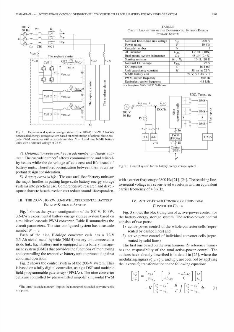
Fig. 1. Experimental system configuration of the 200-V, 10-kW, 3.6-kWhdownscaled energy storage system based on combination of a three-phase cas-cade PWM converter with a cascade number N = 3 and nine NiMH batteryunits with a nominal voltage of 72 V.
7) Optimization between the cascade number and thedc volt-
age: The cascade number2 affects communication and reliabil-
ity issues while the dc voltage affects cost and life issues of
battery units. Therefore, optimization between them is an im-
portant design consideration.
8) Battery cost and life: The cost and life of battery units are
the major hurdles in putting large-scale battery energy storage
systems into practical use. Comprehensive research and devel-
opment have to be achieved on cost reduction and life expansion.
III. THE 200-V, 10-KW, 3.6-KWH EXPERIMENTAL BATTERY
ENERGY STORAGE SYSTEM
Fig. 1 shows the system configuration of the 200-V, 10-kW,
3.6-kWh experimental battery energy storage system based on
a multilevel cascade PWM converter. Table II summarizes the
circuit parameters. The star-configured system has a cascade
number N = 3.
Each of the nine H-bridge converter cells has a 72-V
5.5-Ah nickel-metal-hybride (NiMH) battery unit connected at
its dc link. Each battery unit is equipped with a battery manage-
ment system (BMS) that provides the functions of monitoring
and controlling the respective battery unit to protect it against
abnormal operation.
Fig. 2 shows the control system of the 200-V system. This
is based on a fully digital controller, using a DSP and multiple
field-programmable gate arrays (FPGAs). The nine converter
cells are controlled by phase-shifted unipolar sinusoidal PWM
2The term “cascade number” implies the number of cascaded converter cells
in a phase.
TABLE IICIRCUIT PARAMETERS OF THE EXPERIMENTAL BATTERY ENERGY
STORAGE SYSTEM
Fig. 2. Control system for the battery energy storage system.
with a carrier frequency of 800 Hz [21], [24]. The resulting line-
to-neutral voltage is a seven-level waveform with an equivalent
carrier frequency of 4.8 kHz.
IV. ACTIVE-POWER CONTROL OF INDIVIDUAL
CONVERTER CELLS
Fig. 3 shows the block diagram of active-power control for
the battery energy storage system. The active-power control
consists of two parts:
1) active-power control of the whole converter cells (repre-
sented by dashed lines) and2) active-power control of individual converter cells (repre-
sented by solid lines).
The first one based on the synchronous dq reference frames
has the responsibility of the total active-power control. The
authors have already described it in detail in [25], where the
modulating signals v∗uO , v∗vO , and v∗wO are obtained by applying
the inverse dq transformation to the following equation:
v∗dv∗q
=
vSd
vSq
−
0 −ωLAC
ωLAC 0
idiq
−K i∗d − id
i∗q − iq−
K
T i∗d − id
i∗q − iq dt. (1)

8/3/2019 05512647
http://slidepdf.com/reader/full/05512647 4/9
1102 IEEE TRANSACTIONS ON POWER ELECTRONICS, VOL. 27, NO. 3, MARCH 2012
Fig. 3. Blockdiagramof theactive-powercontrolof thebatteryenergystoragesystem consisting of two parts. The part represented by solid lines is the active-power control of individual converter cells, while that represented by dashedlines is the active-power control of the whole converter cells.
Here, vSd and vS q are the d-axis and q-axis components of v,
while id and iq are those of i. The d-axis current command i∗dand the q-axis current command i∗q are given by
i∗d =p∗
vSd(2)
i∗q =q∗
vSd= 0 (3)
where p∗ is the total active power command, while the reactive
power command of q∗ = 0 ensures unity power factor operation.
Note that the first term on the right-hand side of (1) is a voltagefeedforward control, while the third and fourth terms form a
current feedback control.
The active-power control of the whole converter cells works
under the assumption that all the battery units have the same
power-handling capabilities. This is, however, not always true as
is explained in Section I. Therefore, the active-power control of
individual converter cells is introduced, which is based on mod-
ifying the output signals from the active-power control of the
whole converter cells is such a way that the actual converter-cell
powers P un , P vn , and P wn follow their references with differ-
ent power levels. Its main function is to calculate the amplitude√2 V 0 and phase angle φ0 of the zero-sequence voltage v∗0 to be
injected in such a way as to produce a three-phase balanced line-to-line voltage, even when the nine converter cells are operated
at different power levels. The following is the detailed analysis
of the active-power control of individual converter cells.
If the cascade converter voltage is assumed not to contain any
negative-sequence voltage, it can be expressed as⎡⎣ V uM
V vM
V wM
⎤⎦ =
⎡⎣ V f uM
V f vM
V f wM
⎤⎦+
⎡⎣ V 0
V 0V 0
⎤⎦
= V f M e jφf
⎡⎣
1e− j
2 π3
e j 2 π
3
⎤⎦+ V 0e
jφ0
⎡⎣
11
1
⎤⎦ (4)
where the first term on the right-hand side represents the
positive-sequence voltage with an rms magnitude of V fM and a
phase angle of φf with respect to the u-phase voltage. The sec-
ond term represents the fundamental-frequency zero-sequence
voltage with an rms magnitude of V 0 and a phase angle of φ0 .
Both V 0 and φ0 are adjusted by the active-power control of
individual converter cells.
The line currents are assumed to contain only the following
positive-sequence currents.⎡⎣ I u
I vI w
⎤⎦ = Ie j δ
⎡⎣ 1
e− j2 π
3
e j2 π
3
⎤⎦ (5)
where
I =
I 2d + I 2q
3(6)
δ =
⎧⎪⎪⎨⎪⎪⎩
tan−1 I q
I d , if I d = 0π
2, if I d = 0 and I q > 0
−π
2, if I d = 0 and I q < 0.
(7)
In a sinusoidal steady-state condition, I d and I q are equal to the
d-axis current id and the q-axis current iq . The u-phase power
can be expressed as
P u = ReV uM · I u
= Re
V f uM · I u + V 0 · I u
. (8)
The first term on the right-hand side is the activepower related to
the positive-sequence voltage included in theu-phase ac voltageof the cascade converter, while the second term is the active
power coming from the zero-sequence-voltage injection, which
can be expressed as
P u0 = ReV 0 · ¯I u
= Re[(V 0 (cos φ0 + j sin φ0 ) · I (cos δ + j sin δ)]
= V 0I cos(φ0 − δ). (9)
Similarly, the v- and w-phase powers due to the zero-sequence
voltage can be calculated.
⎡⎣ P u0
P v0
P w0
⎤⎦ = V 0I
⎡⎢⎢⎢⎣
cos(φ0 − δ)
cos
φ0 − δ +
2π
3
cos
φ0 − δ − 2π
3
⎤⎥⎥⎥⎦ . (10)
Let P ∗un , P ∗vn , and P ∗wn be the power commands to the 3N converter cells, where n = 1, 2, . . . N . The three cluster power
commands P ∗u , P ∗v , and P ∗w are given by
⎡⎣
P ∗uP ∗v
P ∗w
⎤⎦ =
⎡⎣
P ∗u1 + P ∗u2 + . . . + P ∗uN
P ∗v1 + P ∗v2 + . . . + P ∗vN
P ∗w1 + P ∗w 2 + . . . + P ∗wN
⎤⎦ . (11)

8/3/2019 05512647
http://slidepdf.com/reader/full/05512647 5/9
MAHARJAN et al.: ACTIVE-POWER CONTROL OF INDIVIDUAL CONVERTER CELLS FOR A BATTERY ENERGY STORAGE SYSTEM 1103
Each of the cluster power commands can be considered as a
sum of two components as follows:⎡⎣ P ∗u
P ∗vP ∗w
⎤⎦ =
P ∗
3+
⎡⎣ ΔP ∗u
ΔP ∗vΔP ∗w
⎤⎦ , (12)
whereP ∗ = P ∗u + P ∗v + P ∗w
. The first term on the right-hand
side of (12) is the active power due to the positive-sequence
voltage. The second term is the active power due to the zero-
sequence voltage. From (10), it is given by
⎡⎣ΔP ∗u
ΔP ∗vΔP ∗w
⎤⎦ = V 0I
⎡⎢⎢⎢⎣
cos(φ0 − δ)
cos
φ0 − δ +
2π
3
cos
φ0 − δ − 2π
3
⎤⎥⎥⎥⎦ . (13)
Solving (13) for V 0 and φ0 results in
φ0 − δ =⎧⎪⎪⎪⎪⎨⎪⎪⎪⎪⎩
tan−1 2
√31
2
+
·ΔP ∗v
ΔP ∗u if ΔP ∗u
= 0
π
2if ΔP ∗u = 0 and ΔP ∗v > 0
−π
2if ΔP ∗u = 0 and ΔP ∗v < 0
(14)
V 0 =ΔP ∗u
I cos(φ0 − δ). (15)
The zero-sequence-voltage reference is determined as
v∗0 =√
2 V 0 sin(ωt + φ0 ). (16)
Finally, the modulating signals to the 3N converter cells are
determined as
v∗un = (v∗uO + v∗0 ) P ∗un
P ∗u(17)
v∗vn = (v∗vO + v∗0 )P ∗vn
P ∗v(18)
v∗wn = (v∗wO + v∗0 )P ∗wn
P ∗w. (19)
Note that when the power-handling capacities of all the 3N battery units are equal, their active power commands are also
equal (P ∗un = P ∗vn = P ∗wn ). Therefore, the modulating signals
would be solely determined by the active-power control of the
whole converter cells.
v∗un =v∗uO
N (20)
v∗vn =v∗vO
N (21)
v∗wn =v∗wO
N . (22)
The active-power control of the individual converter cells is
basically a feedforward control. However, a feedback loop, as
shown in Fig. 4, is used in the experiment to make the 3N converter-cell powers at the dc side, P un , P vn , and P wn equal
to the respective commands at the ac side, P ∗un , P ∗vn , and P ∗wn ,
regardless of the converter-cell losses. The proportional gain
Fig. 4. Feedback loop (taking the u-phase as an example) used in the experi-mentto make theconverter-cellpowersat the dc side,P un equal to the respectivecommands at the ac side, P ∗un , regardless of the converter-cell losses.
Fig. 5. Experimental waveforms when the battery energy storage system wasstarted. (a) CB1 was turned on at t = 0. (b) CB2 was turned on at t = 30 s.(c) Controller was started at t = 2 min.
K 1 and the integral time constant T 1 of the PI controller in the
feedback loop are set as follows:
K 1 = 0.1W/W T 1 = 10 s. (23)
For simplicity, the feedback loop has been neglected from the
earlier analysis.
V. WAVEFORMS DURING STARTUP
Thebattery energy storage system requires no external startup
circuit. Fig. 1 includes a simple startup circuit consisting of the
following two subcircuits:
8/3/2019 05512647
http://slidepdf.com/reader/full/05512647 6/9
1104 IEEE TRANSACTIONS ON POWER ELECTRONICS, VOL. 27, NO. 3, MARCH 2012
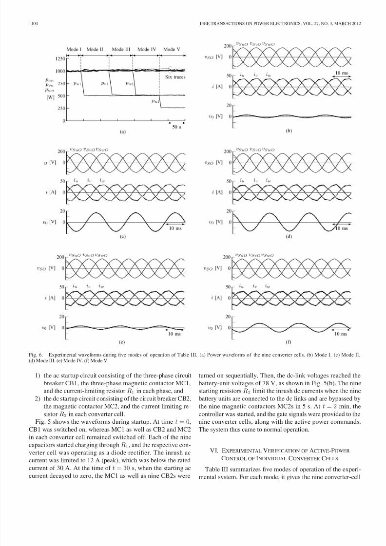
Fig. 6. Experimental waveforms during five modes of operation of Table III. (a) Power waveforms of the nine converter cells. (b) Mode I. (c) Mode II.(d) Mode III. (e) Mode IV. (f) Mode V.
1) the ac startup circuit consisting of the three-phase circuit
breaker CB1, the three-phase magnetic contactor MC1,and the current-limiting resistor R1 in each phase, and
2) the dc startup circuit consisting of the circuit breaker CB2,
the magnetic contactor MC2, and the current limiting re-
sistor R2 in each converter cell.
Fig. 5 shows the waveforms during startup. At time t = 0,
CB1 was switched on, whereas MC1 as well as CB2 and MC2
in each converter cell remained switched off. Each of the nine
capacitors started charging through R1 , and the respective con-
verter cell was operating as a diode rectifier. The inrush ac
current was limited to 12 A (peak), which was below the rated
current of 30 A. At the time of t = 30 s, when the starting ac
current decayed to zero, the MC1 as well as nine CB2s were
turned on sequentially. Then, the dc-link voltages reached the
battery-unit voltages of 78 V, as shown in Fig. 5(b). The ninestarting resistors R2 limit the inrush dc currents when the nine
battery units are connected to the dc links and are bypassed by
the nine magnetic contactors MC2s in 5 s. At t = 2 min, the
controller was started, and the gate signals were provided to the
nine converter cells, along with the active power commands.
The system thus came to normal operation.
VI. EXPERIMENTAL VERIFICATION OF ACTIVE-POWER
CONTROL OF INDIVIDUAL CONVERTER CELLS
Table III summarizes five modes of operation of the experi-
mental system. For each mode, it gives the nine converter-cell
8/3/2019 05512647
http://slidepdf.com/reader/full/05512647 7/9
MAHARJAN et al.: ACTIVE-POWER CONTROL OF INDIVIDUAL CONVERTER CELLS FOR A BATTERY ENERGY STORAGE SYSTEM 1105
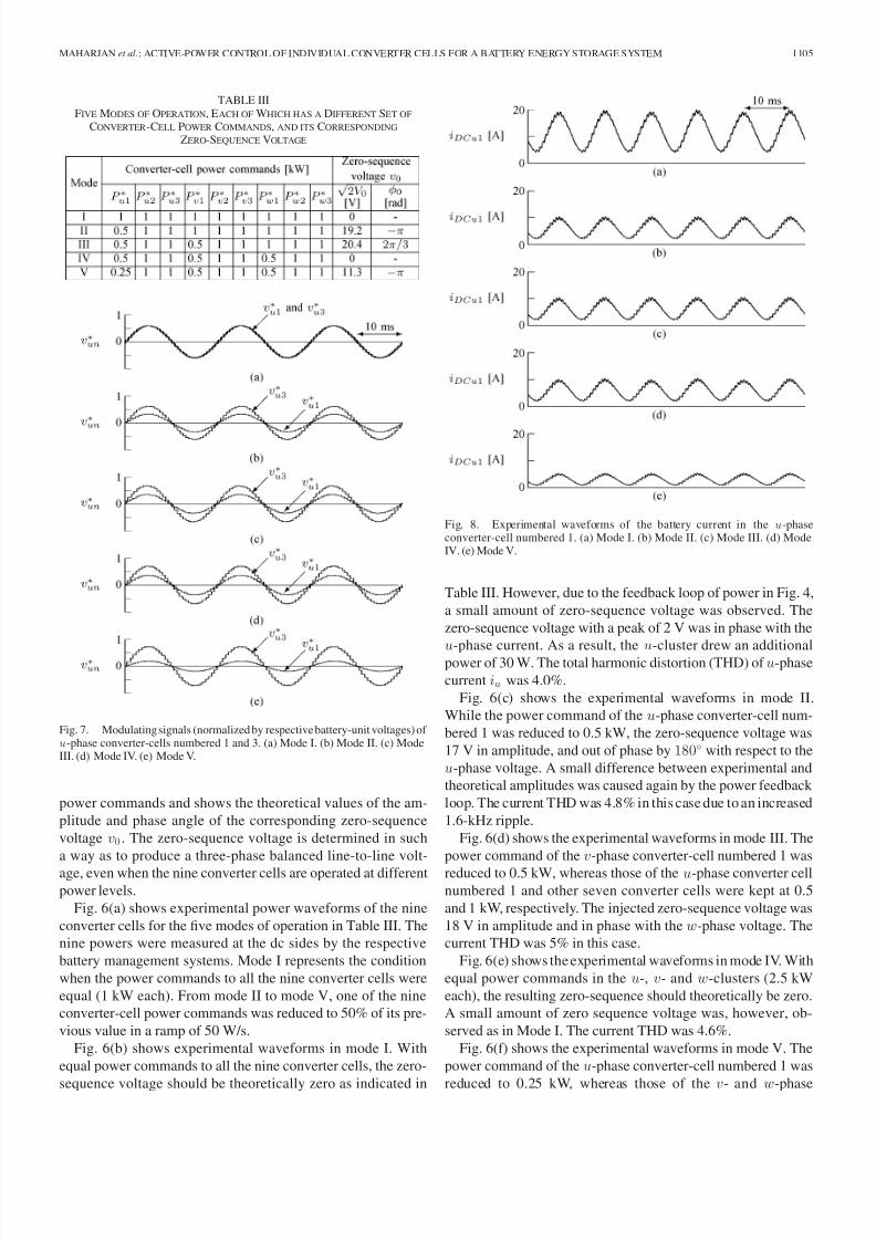
TABLE IIIFIVE MODES OF OPERATION, EACH OF WHICH HAS A DIFFERENT SET OF
CONVERTER-CELL POWER COMMANDS, AND ITS CORRESPONDING
ZERO-SEQUENCE VOLTAGE
Fig. 7. Modulating signals (normalized by respective battery-unit voltages) of u-phase converter-cells numbered 1 and 3. (a) Mode I. (b) Mode II. (c) ModeIII. (d) Mode IV. (e) Mode V.
power commands and shows the theoretical values of the am-
plitude and phase angle of the corresponding zero-sequence
voltage v0 . The zero-sequence voltage is determined in such
a way as to produce a three-phase balanced line-to-line volt-
age, even when the nine converter cells are operated at differentpower levels.
Fig. 6(a) shows experimental power waveforms of the nine
converter cells for the five modes of operation in Table III. The
nine powers were measured at the dc sides by the respective
battery management systems. Mode I represents the condition
when the power commands to all the nine converter cells were
equal (1 kW each). From mode II to mode V, one of the nine
converter-cell power commands was reduced to 50% of its pre-
vious value in a ramp of 50 W/s.
Fig. 6(b) shows experimental waveforms in mode I. With
equal power commands to all the nine converter cells, the zero-
sequence voltage should be theoretically zero as indicated in
Fig. 8. Experimental waveforms of the battery current in the u-phaseconverter-cell numbered 1. (a) Mode I. (b) Mode II. (c) Mode III. (d) ModeIV. (e) Mode V.
Table III. However, due to the feedback loop of power in Fig. 4,
a small amount of zero-sequence voltage was observed. The
zero-sequence voltage with a peak of 2 V was in phase with the
u-phase current. As a result, the u-cluster drew an additionalpower of 30 W. The total harmonic distortion (THD) of u-phase
current iu was 4.0%.
Fig. 6(c) shows the experimental waveforms in mode II.
While the power command of the u-phase converter-cell num-
bered 1 was reduced to 0.5 kW, the zero-sequence voltage was
17 V in amplitude, and out of phase by 180◦ with respect to the
u-phase voltage. A small difference between experimental and
theoretical amplitudes was caused again by the power feedback
loop. The current THD was 4.8% in this case due to an increased
1.6-kHz ripple.
Fig. 6(d) shows the experimental waveforms in mode III. The
power command of the v-phase converter-cell numbered 1 was
reduced to 0.5 kW, whereas those of the u-phase converter cellnumbered 1 and other seven converter cells were kept at 0.5
and 1 kW, respectively. The injected zero-sequence voltage was
18 V in amplitude and in phase with the w-phase voltage. The
current THD was 5% in this case.
Fig. 6(e) shows the experimental waveforms in mode IV. With
equal power commands in the u-, v- and w-clusters (2.5 kW
each), the resulting zero-sequence should theoretically be zero.
A small amount of zero sequence voltage was, however, ob-
served as in Mode I. The current THD was 4.6%.
Fig. 6(f) shows the experimental waveforms in mode V. The
power command of the u-phase converter-cell numbered 1 was
reduced to 0.25 kW, whereas those of the v- and w-phase

8/3/2019 05512647
http://slidepdf.com/reader/full/05512647 8/9
1106 IEEE TRANSACTIONS ON POWER ELECTRONICS, VOL. 27, NO. 3, MARCH 2012
converter cells numbered 1 were kept at 0.5 kW, and those
of the other six converter cells were kept at 1 kW. The resulting
zero-sequence voltage was 9 V in amplitude, and out of phase
by 180◦ with respect to the u-phase voltage. The current THD
was 6%.
Since the same ac current flows through the three converter
cells in a cluster, the desired sharing of power between the
three converter cells in the cluster is achieved by proportionally
controlling the ac voltages of the three converter cells. That
means that, takingu-phase as an example, the following relation
exists as indicated in (17):
V u1
P u1=
V u2
P u2=
V u3
P u3. (24)
Fig. 7 shows the modulating signals (normalized by respec-
tive battery-unit voltages that were assumed equal) of the u-
phase converter cells numbered 1 and 3 for the five modes of
operation. The power command P ∗u3 to the u-phase converter
cell numbered 3 was kept constant at 1 kW throughout the five
modes of operation. Then, the power command P ∗u1 to the u-phase converter cell numbered 1 was changed from 1 to 0.5
kW in mode II, and again from 0.5 to 0.25 kW in mode V. As
a result, the ratio of V ∗u1 to V ∗u3 was changed from 1 to 0.5 in
mode II, and from 0.5 to 0.25 in mode V, as expected.
Fig. 8 shows the battery-unit current idc u1 of the u-phase
converter cell numbered 1 for the five modes of operation. The
battery current contained the 100-Hz component as well as the
1.6-kHz component due to PWM.
VII. CONCLUSION
This paper has described a battery energy storage system
based on a multilevel cascade PWM converter with star con-
figuration from a practical point of view. The presented active-
power control of individual converter cells enables the multiple
battery units to operate at different power levels while produc-
ing a three-phase balanced line-to-line voltage. Experimental
results based on a 200-V, 10-kW, 3.6-kWh system have verified
the effectiveness of the presented active-power control.
REFERENCES
[1] R. Saupe, “The power conditioning system for the ±8.5/17 MW en-ergy storage plant of BEWAG,” in Proc. 3rd Int. Conf. Power Electron.Variable-Speed Drives, Jul. 1988, pp. 218–220.
[2] T. Nakayama,Y. Sera, andA. Mitsuda,“The current statusof developmentof advanced battery electric energy storage systems in Japan,” in Proc. 24th Intersoc. Energy Convers. Eng. Conf. (IECEC 1989), Aug., vol. 3,pp. 1297–1301.
[3] L. H. Walker,“10-MW GTOconverter forbattery peaking service,” IEEETrans. Ind. Appl., vol. 26, no. 1, pp. 63–72, Jan./Feb. 1990.
[4] P. A. Taylor, “Update on the Puerto Rico electric power authority’s spin-ning reserve battery system,”in Proc. IEEE Battery Conf. Appl. Adv., Jan.1996, pp. 249–252.
[5] N. W. Miller, R. S. Zrebiec, R. W. Delmerico, and G. Hunt, “Design andcommissioning of a 5-MVA, 2.5-MWh battery energy storage,” in Proc. IEEE Transmiss. Distrib. Conf., Sep. 1996, pp. 339–345.
[6] T. DeVries, J. McDowall, N. Umbricht, and G. Linhofer, “Cold storage:Thebattery energy storage system for Golden ValleyElectricAssociation,” ABB Rev., vol. 1/2004, pp. 38–43, 2004.
[7] J. Baker, “New technology and possible advances in energy storage,”
Energy Policy, vol. 36, no. 12, pp. 4368 –4373, Dec. 2008.
[8] N. Wade, P. Taylor, P. Lang, and J. Svensson, “Energy storage for powerflow management and voltage control on an 11kV UK distribution net-work,” in Proc. CIRED 2009, Jun., pp. 1–4.
[9] R. H. Baker and L. H. Bannister, “Electric power converter,” U.S. Patent3 867 643, Feb. 1975.
[10] M. Marchesoni, M. Mazzucchelli, and S. Tenconi, “A nonconventionalpower converter for plasma stabilization,” IEEE Trans. Power Electron.,vol. 5, no. 2, pp. 212–219, Apr. 1990.
[11] F. Z. Peng, J. S. Lai, J. W. McKeever, and J. VanCoevering, “A multilevelvoltage-source inverter with separate dc sources for static var generation,” IEEE Trans. Ind. Appl., vol. 32, no. 5, pp. 1130–1138, Sep./Oct. 1996.
[12] P. W. Hammond, “A new approach to enhance power quality for mediumvoltage ac drives,” IEEE Trans. Ind. Appl., vol. 33, no. 1, pp. 202–208,Jan./Feb. 1997.
[13] J. D. Ainsworth, M. Davies, P. J. Fitz, K. E. Owen, and D. R. Trainer,“Static var compensator (STATCOM) based on single phase chain circuitconverters,” IEE Proc.—Gener. Transm. Distrib., vol. 145, no. 4,pp. 381–386, Jul. 1998.
[14] J. Rodriguez, S. Bernet, B. Wu, J. O. Pontt, and S. Kouro, “Multi-level voltage-source-converter topologies for industrial medium-voltagedrives,” IEEE Trans. Ind. Electron., vol. 54, no. 6, pp. 2930–2945, Dec.2007.
[15] L. Maharjan, S. Inoue, H. Akagi, and J. Asakura, “SOC (state-of-charge)-balancing control of a battery energy storage system based on a cascadePWM converter,” IEEE Trans. Power Electron., vol. 24, no. 6, pp. 1628–
1636, Jun. 2009.[16] L. Laxman, T. Yamagishi, H. Akagi, andJ. Asakura,“Fault-tolerant controlfor a battery energy storage system based on a cascade PWM converterwith star configuration” IEEE Trans. Power Electron., vol. 25, no. 9, pp.2386–2396, Sep. 2010.
[17] L. M. Tolbert, F. Z. Peng, and T. G. Habetler, “Multilevel converters forlarge electric drives,” IEEE Trans. Ind. Appl., vol. 35, no. 1, pp. 36–44,Jan./Feb. 1999.
[18] S. Wei, B. Wu, F. Li, and X. Sun, “Control method for cascaded H-brigemultilevel inverter with faulty power cells,” in Proc. IEEE APEC, Feb.2003, vol. 1, pp. 261–267.
[19] J. Rodriguez, P. W. Hammond, J. Pontt, R. Musalem, P. Lezana, and M. J.Escobar, “Operation of a medium-voltage drive under faulty conditions,” IEEE Trans. Ind. Electron., vol. 52, no. 4, pp. 1080–1085, Aug. 2005.
[20] W. Song and A. Q. Huang, “Control strategy for fault-tolerant cascadedmultilevel converter based STATCOM,” in Proc. IEEE APEC, Feb./Mar.2007, pp. 1073–1076.
[21] Y. Liang andC. O. Nwankpa,“A new type of STATCOM based on cascad-ing voltage-source inverters with phase-shifted unipolar SPWM,” IEEETrans. Ind. Appl., vol. 35, no. 5, pp. 1118–1123, Sep./Oct. 1999.
[22] N. H. Kutkut and D. M. Divan, “Dynamic equalization techniques forseries battery stacks,” in Proc. IEEE INTELEC 1996 , Oct., pp. 514–521.
[23] S. W. Moore and P. J. Schneider, “A review of cell equalization methodsfor lithium ion and lithium polymer battery systems,” in Proc. SAE World Congress, Mar. 2001, Doc. No 2001-01-0959.
[24] D.G. Holmes andB. P. McGrath,“Opportunities forharmoniccancellationwith carrier-based PWM for two-level and multilevel cascaded inverters,” IEEE Trans. Ind. Appl., vol. 37, no. 2, pp. 574–582, Mar./Apr. 2001.
[25] L. Maharjan, T. Yoshii, S. Inoue, and H. Akagi, “A transformerless energystorage system based on a cascade PWM converter with star configura-tion,” IEEE Trans. Ind. Appl., vol. 44, no. 5, pp. 1621–1630, Sep./Oct.2008.
Laxman Maharjan (S’06–M’10) was born in Lalit-pur, Nepal, on January 2, 1979. He received the B.E.degree in electrical engineering from Institute of En-gineering, Tribhuvan University, Lalitpur, Nepal, in2002, and the M.S. and Ph.D. degrees in electricaland electronic engineering from Tokyo Institute of Technology, Tokyo, Japan, in 2007 and 2010, respec-tively.
From October 2004 to March 2005, he was aResearch Student in Tokyo Institute of Technology.Since 2010, he has been with Fuji Electric Company
Ltd. His current research interests include multilevel cascade converters and
energy storage systems.

8/3/2019 05512647
http://slidepdf.com/reader/full/05512647 9/9
MAHARJAN et al.: ACTIVE-POWER CONTROL OF INDIVIDUAL CONVERTER CELLS FOR A BATTERY ENERGY STORAGE SYSTEM 1107
Tsukasa Yamagishi was born on June 15, 1985. Hereceived the B.S. and M.S. degrees in electrical andelectronic engineering from Tokyo Institute of Tech-nology, Tokyo, Japan, in 2008and 2010, respectively.
Since 2010, he has been with Mitsubishi HeavyIndustries Ltd. His current research interests includemultilevel cascade converters.
Hirofumi Akagi (M’87–SM’94–F’96) was born inOkayama, Japan, in 1951. He received the B.S.degree from the Nagoya Institute of Technology,Nagoya, Japan, in 1974, and the M.S. and Ph.D. de-grees from the Tokyo Institute of Technology, Tokyo,Japan, in 1976 and1979, respectively, all in electricalengineering.
In 1979, he joined theNagaokaUniversity of Tech-nology, Nagaoka, Japan, as an Assistant Professorand then Associate Professor in the Department of Electrical Engineering. In 1987, he was a Visiting
Scientist at the Massachusetts Institute of Technology (MIT), Cambridge, fortenmonths.From 1991 to 1999,he wasa Professorin theDepartment of Electri-cal Engineering, Okayama University, Okayama, Japan. From March to Augustof 1996, he was a Visiting Professor at the University of Wisconsin, Madison,and then MIT. Since January 2000, he has been a Professor in the Departmentof Electrical and Electronic Engineering at the Tokyo Institute of Technology.He is the author or coauthor more than 100 IEEE Transactions papers and twoinvited papers publishedin Proceedings of the IEEE in 2001 and2004. Thetotalcitation index for all his papers in Google Scholar is more than 15 000. He hasmade presentations many times as a keynote or invited speaker internationally.His current research interests include power conversion systems, motor drives,active and passive EMI filters, high-frequency resonant inverters for inductionheating and corona discharge treatment processes, and utility applications of power electronics such as active filters, self-commutated back-to-back systems,
and flexible ac transmission systems devices.Prof. Akagi served as the President of the IEEE Power Electronics Soci-ety from 2007 to 2008, and is currently the Senior Past President. He waselected as a Distinguished Lecturer of the IEEE Power Electronics and Indus-try Applications Societies during 1998–1999. He was the recipient of the fiveIEEE Transactions Prize Paper Awards and nine IEEE Conference Prize PaperAwards, the 2001 IEEE William E. Newell Power Electronics Award, the 2004IEEE Industry Applications Society Outstanding Achievement Award, and the2008 IEEE Richard H. Kaufmann Technical Field Award.


