Embed Size (px)
Citation preview
1EWM CustomerStory / April 2018
Agitator vessels are used wherever something needs to be stirred on an industrial scale – in the chemical in-dustry as well as in the pharmaceutical industry or in food technology. AST Apparatebau GmbH from Wilnsdorf in Germany manufactures agitator ves-sels of this type.
The media in agitator vessels aren’t just stirred – they’re also heated or cooled depending on the respective con-tents. In wax production, for example, di� erent media are further processed at di� erent temperatures in agitator ves-sels. In the pharmaceutical industry, jackets even cool the contents of the agitator vessels all the way down to minus 80 degrees Celsius.
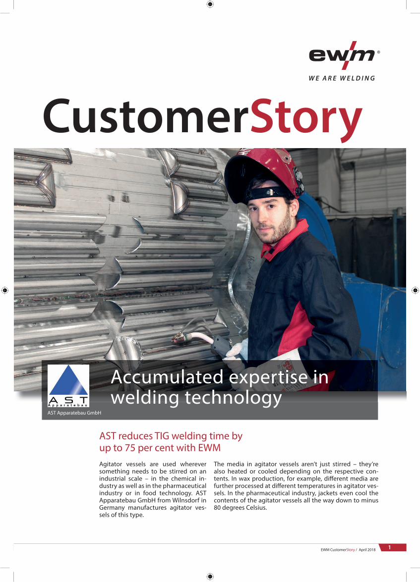
AST reduces TIG welding time by up to 75 per cent with EWM
Accumulated expertise in welding technology
AST Apparatebau GmbH
CustomerStory

2
CustomerStory / AST Apparatebau GmbH
Heating or cooling in agitator vessels is carried out by means of a half-pipe coil. It is usually welded onto the vessel wall in a spiral formation. Half-pipes are pipes cut longitudinally. The top of the vessel is also the bottom of the pipe at the same time. The cooling or heating liquid � ows inside this, and there is a direct exchange of heat between the liquid and the ves-sel. This is the perfect way to harness the heat, which is then supplied or dissipated via the vessel wall directly. The diameter of such an agitator vessel is between 80 centimetres and 2.5 metres, and the length of the weld seams created can range from almost ten metres to sev-eral hundred metres in total.
The demands on these weld seams are high. The industrial standards of major chemical companies prescribe speci� c weld preparations for the half-pipes as well as di� erentiated versions. For example, the half-pipes must have a bevel of between 30 degrees and 45 degrees on the inside and be pointed towards the bottom. Root pass weld-ing is conducted in a protective gas at-mosphere for forming. A clearly recog-nisable golden yellow iridescent root forms from the inside. Following this, an endoscope is used to determine whether the requirements are met. Typical joining processes for seams like this are TIG welding for the root pass and MAG welding for the cover pass. The estimated welding time for one metre of TIG weld seam for the root pass is 20 to 25 minutes.
High-quality weld seams required
EWM CustomerStory / April 2018
Special design of an agitator vessel. The entire surface of the vessel should be covered with cooling coils.
Welded-on half-pipe. The inside of the half-pipe is bevelled. The root of the TIG weld seam (red) pushes inwards. With the second pass, a MAG seam (yellow), the required throat thickness is achieved.
Agitator vessels: many metres of weld seam
3EWM CustomerStory / April 2018
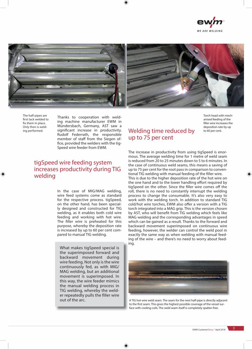
Torch head with mech-anised feeding of the � ller wire increases the deposition rate by up to 60 per cent.
A TIG hot wire weld seam. The seam for the next half-pipe is directly adjacent to the � rst seam. This gives the highest possible coverage of the vessel sur-face with cooling coils. The weld seam itself is completely spatter-free.
Thanks to cooperation with weld-ing machine manufacturer EWM in Mündersbach, Germany, AST saw a signi� cant increase in productivity. Rudolf Federrath, the responsible member of sta� from the Siegen of-� ce, provided the welders with the tig-Speed wire feeder from EWM.
In the case of MIG/MAG welding, wire feed systems come as standard for the respective process. tigSpeed, on the other hand, has been special-ly designed and constructed for TIG welding, as it enables both cold wire feeding and working with hot wire. The � ller wire is preheated for this purpose, whereby the deposition rate is increased by up to 60 per cent com-pared to manual TIG welding.
What makes tigSpeed special is the superimposed forward and backward movement during wire feeding. Not only is the wire continuously fed, as with MIG/MAG welding, but an additional movement is superimposed. In this way, the wire feeder mimics the manual welding process in TIG welding, whereby the weld-er repeatedly pulls the � ller wire out of the arc.
The increase in productivity from using tigSpeed is enor-mous. The average welding time for 1 metre of weld seam is reduced from 20 to 25 minutes down to 5 to 6 minutes. In the case of continuous weld seams, this means a saving of up to 75 per cent for the root pass in comparison to conven-tional TIG welding with manual feeding of the � ller wire. This is due to the higher deposition rate of the hot wire on the one hand and to the lower handling e� ort required by tigSpeed on the other. Since the � ller wire comes o� the roll, there is no need to constantly interrupt the welding process to change the consumable. It’s also very easy to work with the welding torch. In addition to standard TIG cold/hot wire torches, EWM also o� er a version with a TIG torch integrated into a MAG grip. This is the version chosen by AST, who will bene� t from TIG welding which feels like MAG welding and the corresponding advantages in speed which can be gained as a result. Thanks to the forward and backward movement superimposed on continuous wire feeding, however, the welder can control the weld pool in exactly the same way as when welding with manual feed-ing of the wire – and there’s no need to worry about feed-ing.
The half-pipes are � rst tack welded to � x them in place. Only then is weld-ing performed.
tigSpeed wire feeding system increases productivity during TIG welding
Welding time reduced by up to 75 per cent
053-000044-00001 / April 2018The content of this document has been prepared and reviewed with all reasonable care. The information provided is subject to change, errors excepted.
4
CustomerStory / AST Apparatebau GmbH
EWM AG / Dr. Günter-Henle-Straße 8 / 56271 Mündersbach / GermanyFon: +49 2680 181-0 / [email protected] / www.ewm-group.com
Photos: EWM AG, AST Apparatebau GmbH
Happy faces: Joachim Jung, AST Technical Manager; Rudolf Federrath, EWM Branch Siegen; Dietmar Simmert, AST Commercial Manager
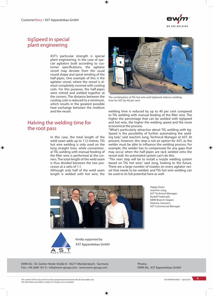
The combination of TIG hot wire and tigSpeed reduces welding time for AST by 40 per cent.
AST’s particular strength is special plant engineering. In the case of spe-cial agitators built according to cus-tomer speci� cations, the agitator vessel may deviate from the usual round shape and spiral winding of the half-pipes. One example of this is the agitator vessel, where the vessel is al-most completely covered with cooling coils. For this purpose, the half-pipes were mitred and welded together at the corners. The distance between the cooling coils is reduced to a minimum, which results in the greatest possible heat exchange between the medium and the vessel.
In this case, the total length of the weld seam adds up to 112 metres. TIG hot wire welding is only used on the long straight lines, while convention-al TIG welding with manual feeding of the � ller wire is performed at the cor-ners. The total length of the weld seam is thus divided between the two pro-cesses at a ratio of 1:1. Although only half of the weld seam length is welded with hot wire, the
welding time is reduced by up to 40 per cent compared to TIG welding with manual feeding of the � ller wire. The higher the percentage that can be welded with tigSpeed and hot wire, the higher the welding speed and the more economical the process. “What’s particularly attractive about TIG welding with tig-Speed is the possibility of further automating the weld-ing task,” said Joachim Jung, Technical Manager at AST. At present, however, this step is not an option for AST, as the welder must be able to in� uence the welding process. For example, the welder has to compensate for any gaps that may occur when the half-pipes are tack welded onto the vessel wall. An automated system can’t do this.“The next step will be to install a nozzle welding system based on TIG hot wire,” said Jung, looking to the future. There are a large number of nozzles on every agitator ves-sel that needs to be welded, and TIG hot wire welding can be used to its full potential here as well.
tigSpeed in special plant engineering
Halving the welding time for the root pass
AST Apparatebau GmbH
Kindly supported by


![PRESSURE VESSEL [Proses Pembuatan Pressure Vessel]](https://img.dokumen.tips/doc/110x75/546b26fab4af9fc2128b4e24/pressure-vessel-proses-pembuatan-pressure-vessel.jpg)