Embed Size (px)
Citation preview

ECE 5616Curtis
Ray Optics
• Thin lens• imaging condition
• Graphical Ray Tracing• Real and Virtual Images• Magnification• Scheimpflug condition
ECE 5616Curtis
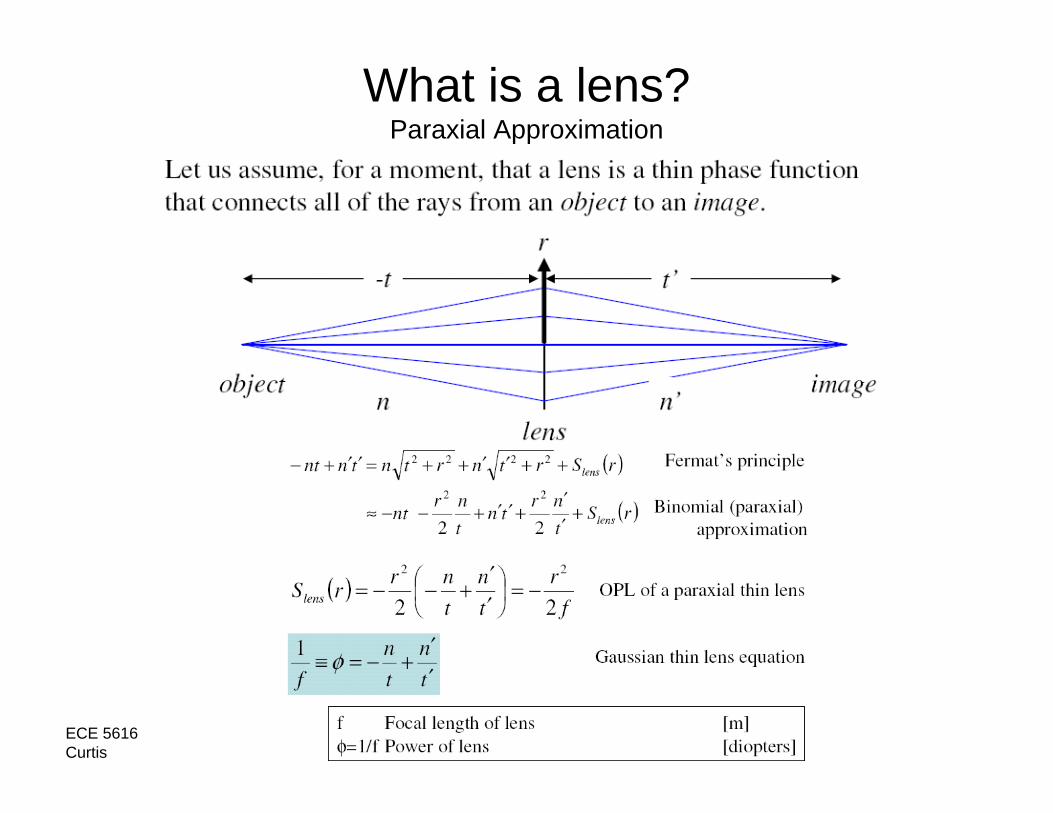
What is a lens?Paraxial Approximation

ECE 5616Curtis
Power of a lens Physical Meaning

ECE 5616Curtis
Question
Two thin lenses with F1=10mm and F2=10mm are in contact – what is the total focal length ?
ϕ =1/f = 1/10 + 1/10 = 1/5
F = 5mm
ECE 5616Curtis
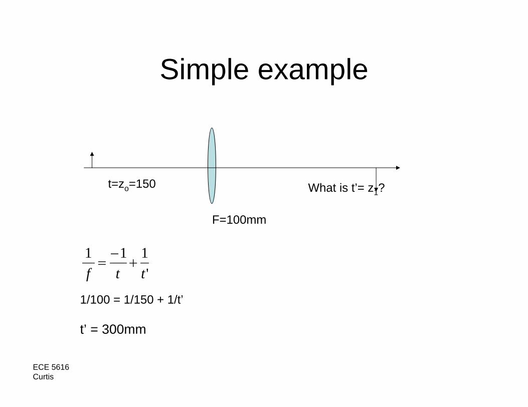
Simple example
F=100mm
t=zo=150 What is t’= z1?
'111ttf
+−
=
1/100 = 1/150 + 1/t’
t’ = 300mm

ECE 5616Curtis
General Types of Lens+, - -, -∞, -
ECE 5616Curtis
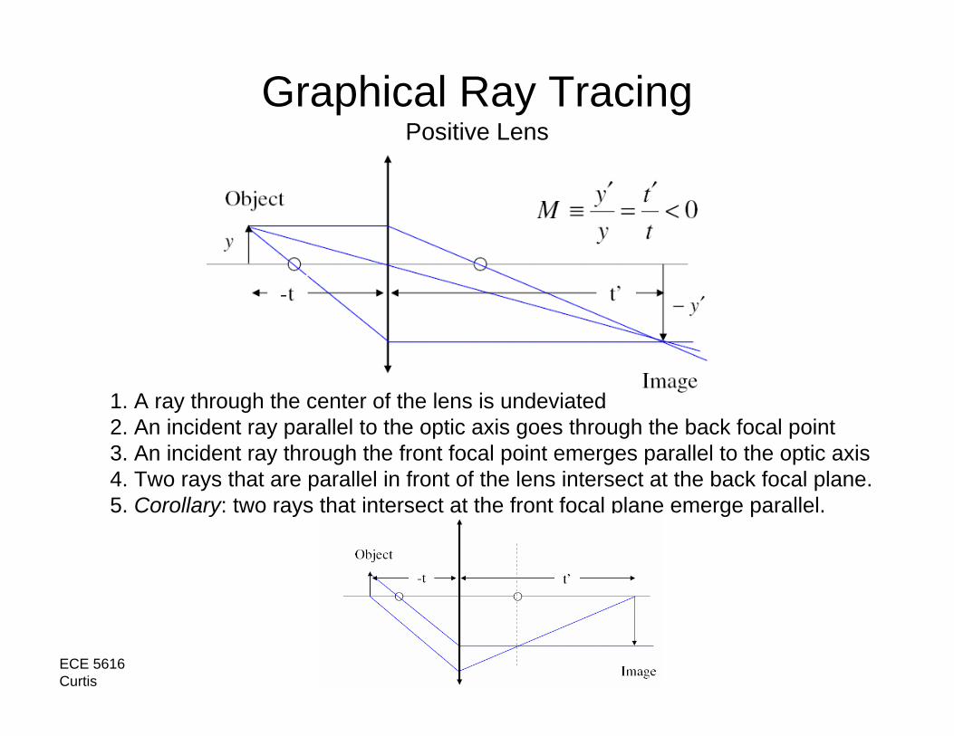
Graphical Ray TracingPositive Lens
1. A ray through the center of the lens is undeviated2. An incident ray parallel to the optic axis goes through the back focal point3. An incident ray through the front focal point emerges parallel to the optic axis 4. Two rays that are parallel in front of the lens intersect at the back focal plane.5. Corollary: two rays that intersect at the front focal plane emerge parallel.

ECE 5616Curtis
Example – 2 positive lens
F F F F

ECE 5616Curtis
Graphical Ray TracingNegative Lens
1. A ray through the center of the lens is undeviated2. An incident ray parallel to the optic axis appears to emerge from the front focal point3. An incident ray directed towards the back focal point emerges parallel to the optic axis.

ECE 5616Curtis
Example
F F F

ECE 5616Curtis
Real and Virtual Images and Objects
If you can’t see the light by placing a screen at the planewhere it is in focus, then it is virtual.Equivalently, an image is virtual if you need another lens(e.g. an eye) to make the image real.Equivalently, real (virtual) objects are to the left (right) ofthe surface and real (virtual) images are to the right (left).
ECE 5616Curtis
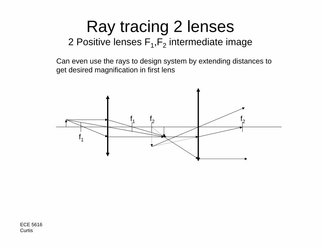
Ray tracing 2 lenses2 Positive lenses F1,F2 intermediate image
f1
f1 f2 f2
Can even use the rays to design system by extending distances toget desired magnification in first lens
ECE 5616Curtis
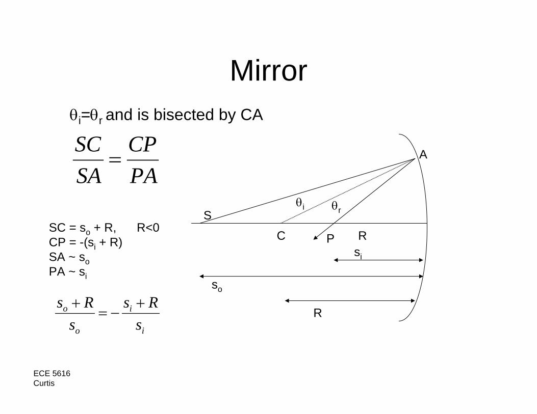
Mirror
PACP
SASC
=
C R
S
P
so
θi θr
si
θi=θr and is bisected by CA
A
SC = so + R, R<0CP = -(si + R)SA ~ soPA ~ si
Ri
i
o
o
sRs
sRs +
−=+

ECE 5616Curtis
Mirror Formula
C CF F
1/so + 1/si = -2/R
R > 0 R < 0
-> F = -R/2
R

ECE 5616Curtis
Ray Tracing MirrorsReal Images
Mirror System
ECE 5616Curtis
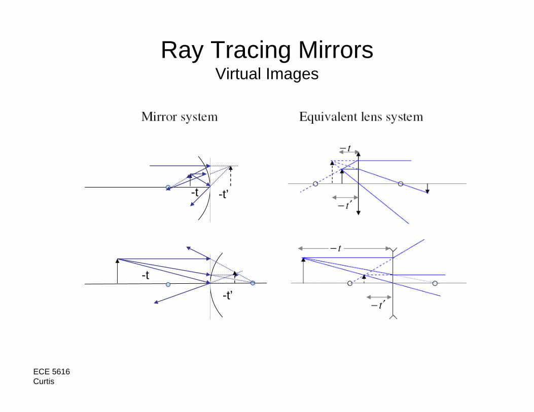
Ray Tracing MirrorsVirtual Images
-t’-t
-t
-t’

ECE 5616Curtis
Thin Lens Equations
(Focal length of lens is constant)

ECE 5616Curtis
Thin Lens Equations
Note: Smith usesz->xt->z
Note: lens in same index both sidesotherwise
y/-y’ = -z/f
-y’
zz’ = -nn’F2
y/-y’ = f/z’
y
M = -z’/fM = f/zt’ = f(1-M)t = f(1/M-1)

ECE 5616Curtis
Newton’s Equation ExampleGiven image is 5mm high, F=10mm and image is located 40mm left of focal point of lens (50mm from lens): What is the image position, size and magnification ?
x’ = -f2/xx’ = -102/40 = 2.5mm to the right of right focal point
40 10
M= f/x = 10/-40 = -0.25
h’= Mh = (-0.25)(5mm) = -1.25mm
Ml = M2 = (-0.25)2 = 0.0625
hh’
x’

ECE 5616Curtis
Angular Magnification
Remember the radiometric unit L = radiance (or photometric “brightness”) in units of [W/(sr m2)]? We just found that as size of an object goes up, it’s angular extent decreases by the same amount. Brightness is conserved.

ECE 5616Curtis
Another ExampleObject is 5mm high, located 2mm to right of front focal plane oflens F=10mm. Where is the image located, what is the image height, magnification (x,l,θ) of system ?
First lens ray trace to see what to expect…
ff
Magnified (positive) virtual image at a negative distance !
ECE 5616Curtis
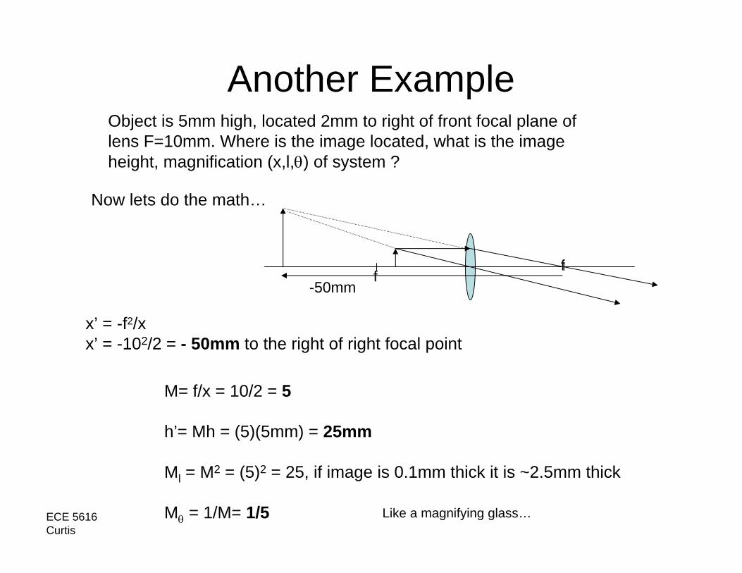
Another ExampleObject is 5mm high, located 2mm to right of front focal plane oflens F=10mm. Where is the image located, what is the image height, magnification (x,l,θ) of system ?
Now lets do the math…
ff
x’ = -f2/xx’ = -102/2 = - 50mm to the right of right focal point
M= f/x = 10/2 = 5
h’= Mh = (5)(5mm) = 25mm
Ml = M2 = (5)2 = 25, if image is 0.1mm thick it is ~2.5mm thick
Mθ = 1/M= 1/5
-50mm
Like a magnifying glass…

ECE 5616Curtis
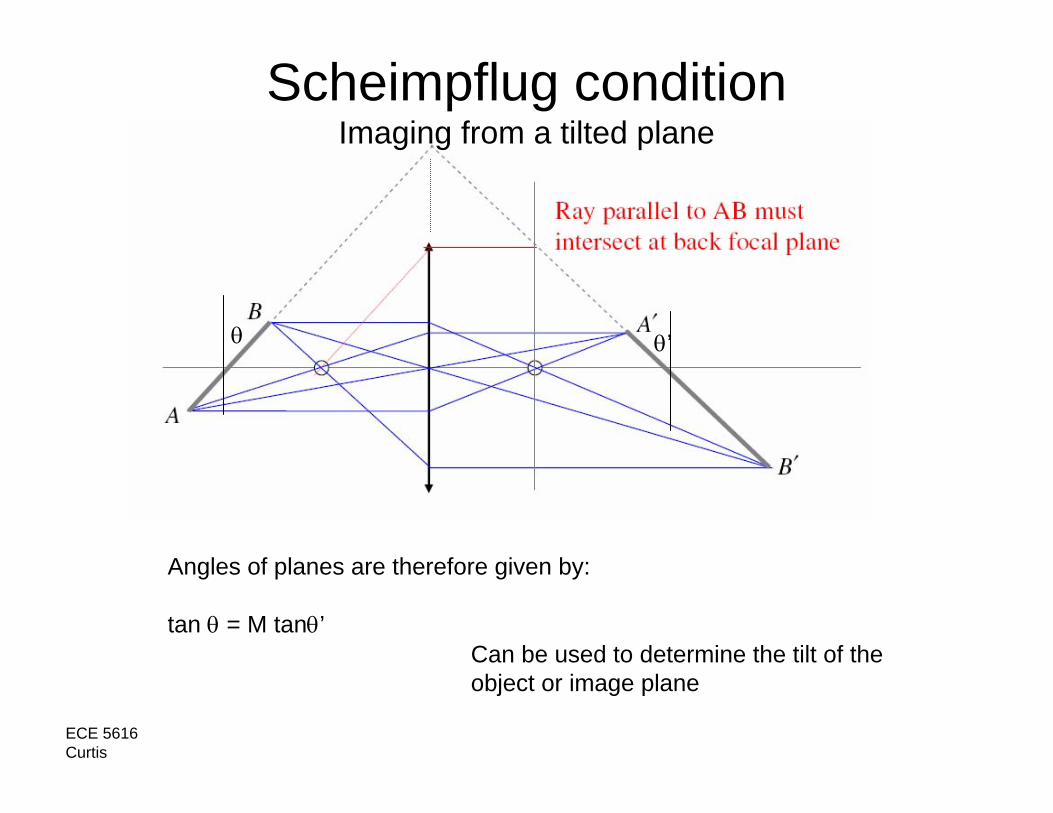
Scheimpflug conditionImaging from a tilted plane
ECE 5616Curtis
Scheimpflug conditionImaging from a tilted plane
Angles of planes are therefore given by:
tan θ = M tanθ’
θ θ’
Can be used to determine the tilt of the object or image plane
ECE 5616Curtis
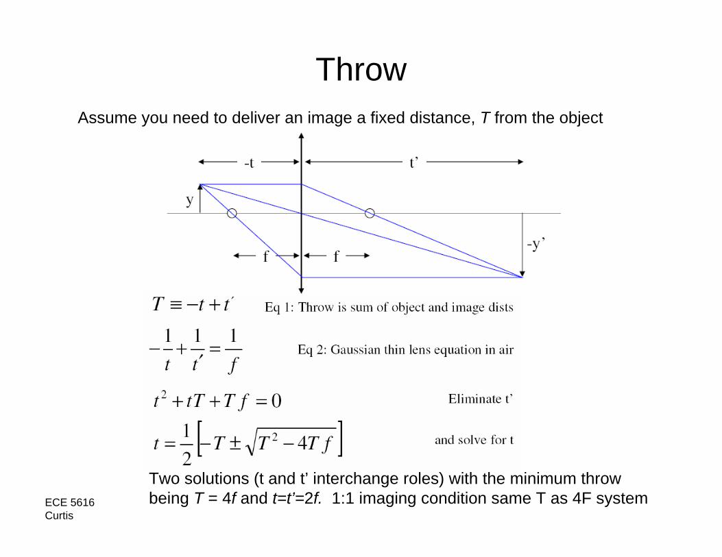
ThrowAssume you need to deliver an image a fixed distance, T from the object
Two solutions (t and t’ interchange roles) with the minimum throw being T = 4f and t=t’=2f. 1:1 imaging condition same T as 4F system
ECE 5616Curtis
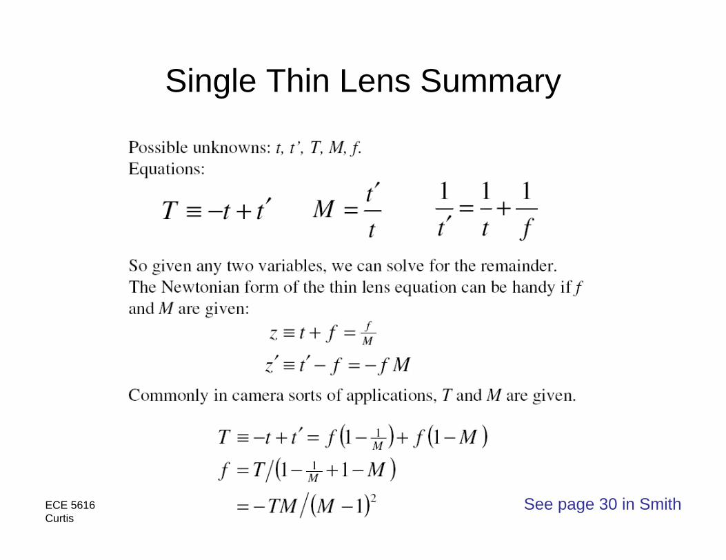
Single Thin Lens Summary
See page 30 in Smith
ECE 5616Curtis
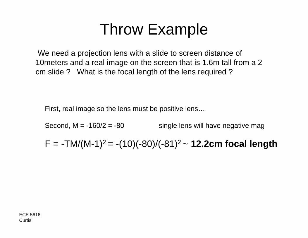
Throw ExampleWe need a projection lens with a slide to screen distance of
10meters and a real image on the screen that is 1.6m tall from a 2 cm slide ? What is the focal length of the lens required ?
First, real image so the lens must be positive lens…
Second, M = -160/2 = -80 single lens will have negative mag
F = -TM/(M-1)2 = -(10)(-80)/(-81)2 ~ 12.2cm focal length
ECE 5616Curtis
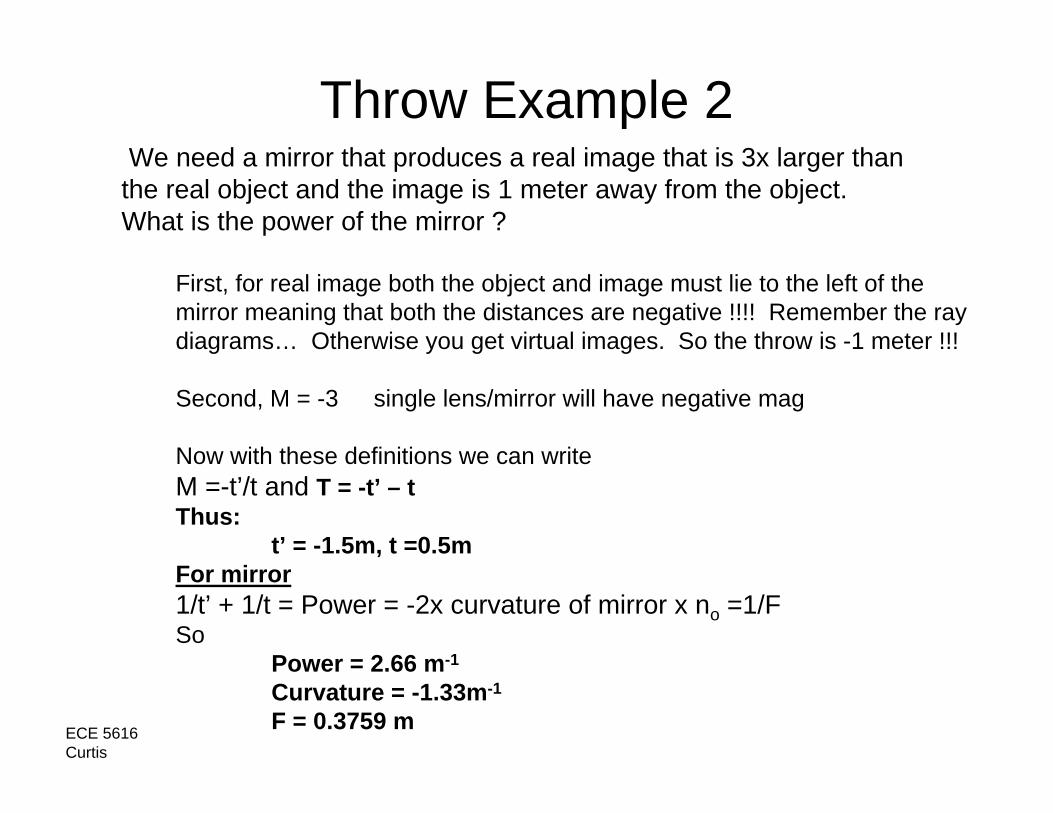
Throw Example 2We need a mirror that produces a real image that is 3x larger than
the real object and the image is 1 meter away from the object. What is the power of the mirror ?
First, for real image both the object and image must lie to the left of the mirror meaning that both the distances are negative !!!! Remember the ray diagrams… Otherwise you get virtual images. So the throw is -1 meter !!!
Second, M = -3 single lens/mirror will have negative mag
Now with these definitions we can writeM =-t’/t and T = -t’ – tThus:
t’ = -1.5m, t =0.5mFor mirror1/t’ + 1/t = Power = -2x curvature of mirror x no =1/FSo
Power = 2.66 m-1
Curvature = -1.33m-1
F = 0.3759 m
ECE 5616Curtis
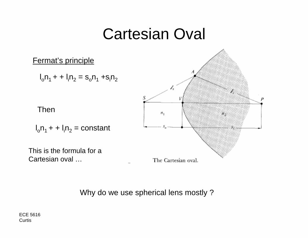
Cartesian Oval
Why do we use spherical lens mostly ?
Fermat’s principle
lon1 + + lin2 = son1 +sin2
Then
lon1 + + lin2 = constant
This is the formula for a Cartesian oval …