Embed Size (px)
Citation preview

www.fpinnovations.ca
Structural Performance and Design of CLT Building
™
Sylvain Gagnon, Eng.M. Mohammad, Ph.D., P.Eng.
CLT Symposium and WorkshopOctober 12, 2011Moncton, NB

Outline
What is Cross Laminated Timber (CLT)– Advantages– Basic Configurations & properties
Structural Design of CLT Elements/Assemblies– Floors/roof slabs– Walls– Beams and Lintels
Connections Techniques in CLT Assemblies Seismic Performance of CLT Assemblies

New generation of lightweight and prefabricated systems
Consists of wood strips (planks) stacked crosswise on top of each other (glued or nailed)
Thicknesses of the panels vary from50 to 600 mm
•••••
•Cross-Laminated Timber
18/10/2011 3

© 2009 FPInnovations. All rights reserved. Copying and redistribution prohibited.
27/10/2011
CLT Assemblies
A series of prefabricated CLT panels connected together on site to form an assembly or a building
Quick on-site erection due to- High degree of prefab. - Ease of assembly using conventional & innovative fasteners
Source: Kevin MeechanCourtesy WoodWorks

•••••
•Advantages of CLT Panels
X-lamination minimizes swelling & shrinkage in the board plane
Relatively high in-plane (seismic) & out-of-plane (wind) strength and stiffness
Good seismic & fire resistance –heavy timber construction (i.e., inherent fire resistance)
18/10/2011 5

Why CLT is Different than Glulam?!
•Beam-like member•Thick Orthotropic Plate
18/10/2011 6
•••••
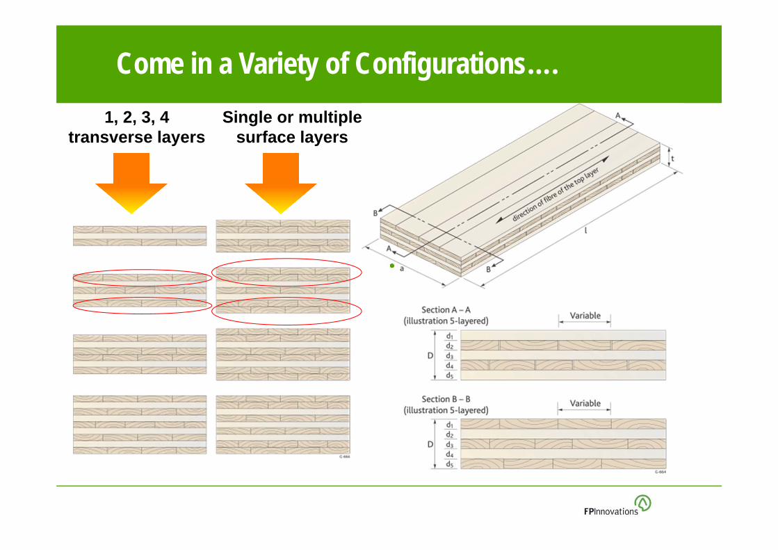
•Come in a Variety of Configurations….Single or multiple
surface layers1, 2, 3, 4
transverse layers
© 2009 FPInnovations. All rights reserved. Copying and redistribution prohibited.
27/10/2011 8
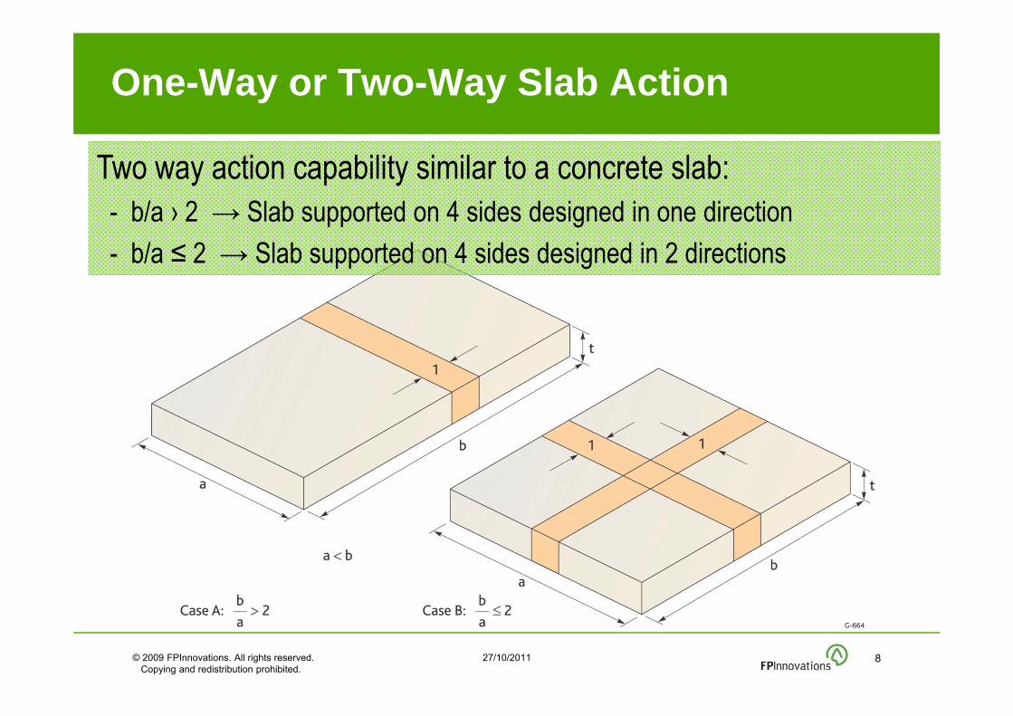
One-Way or Two-Way Slab Action
Two way action capability similar to a concrete slab:- b/a › 2 → Slab supported on 4 sides designed in one direction- b/a ≤ 2 → Slab supported on 4 sides designed in 2 directions

© 2009 FPInnovations. All rights reserved. Copying and redistribution prohibited.
27/10/2011 9
Lumber Properties
Dimensions
– Thickness of boards varies from ~15 mm to ~50 mm
– Width of boards may varies considerably (63 ~ 235 mm)
MC: 12% ± 3%

© 2009 FPInnovations. All rights reserved. Copying and redistribution prohibited.
27/10/2011 10
Lumber Properties for Floor/Roof Panels
– Longitudinal Layers• MSR 1650Fb-1.5E (or Better)• Visual Grade No1/No2• SCL (proprietary)
– Transverse Layers• Visual Grade No3/Stud (or
Better)• SCL (proprietary)

© 2009 FPInnovations. All rights reserved. Copying and redistribution prohibited.
27/10/2011 11
Lumber Properties for Wall Panels
Lumber grades for walls
– Vertical Layers
• Visual Grade No1/No2• SCL (proprietary)
– Horizontal Layers/Transverse
• Visual Grade No3/Stud• SCL (proprietary)
© 2009 FPInnovations. All rights reserved. Copying and redistribution prohibited.
27/10/2011 12
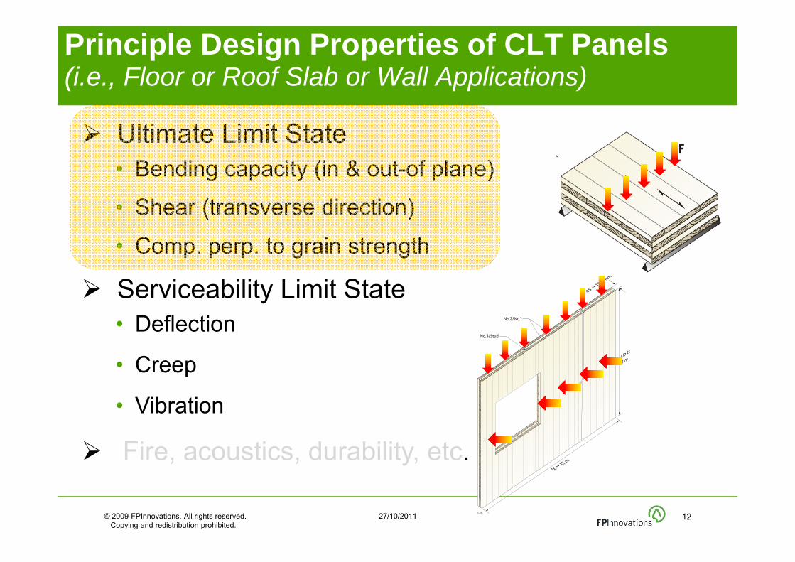
Ultimate Limit State• Bending capacity (in & out-of plane)
• Shear (transverse direction)
• Comp. perp. to grain strength
Serviceability Limit State• Deflection
• Creep
• Vibration
Fire, acoustics, durability, etc.
Principle Design Properties of CLT Panels (i.e., Floor or Roof Slab or Wall Applications)

© 2009 FPInnovations. All rights reserved. Copying and redistribution prohibited.
27/10/2011 13
Structural Design Principles of
CLT Elements
•Source: Structurlam

February 08, 201114
Wood = low rolling shear Significant deformations
•Stresses due to rolling shear
Rolling Shear Strength & Modulus
Rolling Shear failure
Rolling Shear strength & stiffness of transverse layers may control the design of CLT floor or wall
© 2009 FPInnovations. All rights reserved. Copying and redistribution prohibited.
27/10/2011 15
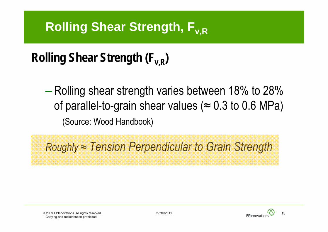
Rolling Shear Strength (Fv,R)
– Rolling shear strength varies between 18% to 28% of parallel-to-grain shear values (≈ 0.3 to 0.6 MPa)
(Source: Wood Handbook)
Roughly ≈ Tension Perpendicular to Grain Strength
Rolling Shear Strength, Fv,R
© 2009 FPInnovations. All rights reserved. Copying and redistribution prohibited.
27/10/2011 16
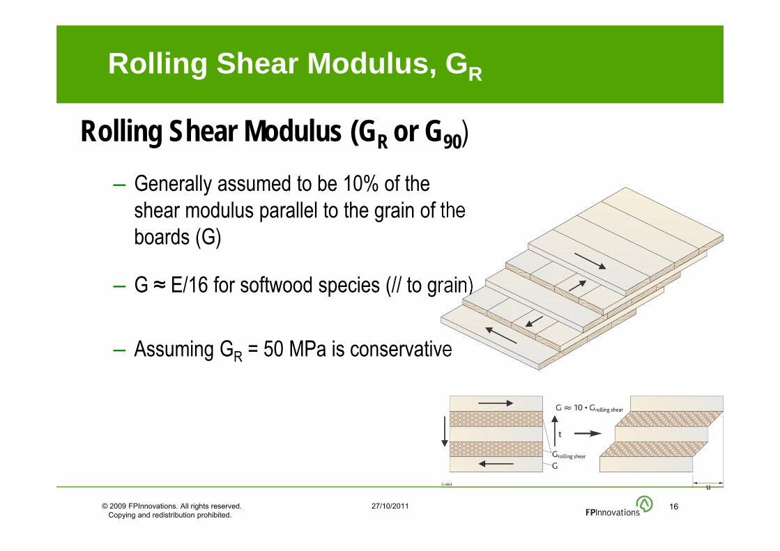
Rolling Shear Modulus (GR or G90)– Generally assumed to be 10% of the
shear modulus parallel to the grain of the boards (G)
– G ≈ E/16 for softwood species (// to grain)
– Assuming GR = 50 MPa is conservative
Rolling Shear Modulus, GR

FPInnovations CLT Handbook
18/10/2011 17
• Provides information on how to determine the engineering properties of CLT elements by using the properties of individual laminations

© 2009 FPInnovations. All rights reserved. Copying and redistribution prohibited.
27/10/2011 18
Determination of Design Properties of CLT
Different methods adopted in Europe
Some methods are experimental, while others are analytical
Experimental: Flexural properties determined by testing sections or full-size panels: configuration specific
Analytical methods more versatile and less costly alternative once verified
Analytical approach can predict strength & stiffness properties of CLT element based on lamina properties
No analytical approach has been universally accepted by CLT manufactures in Europe as yet

© 2009 FPInnovations. All rights reserved. Copying and redistribution prohibited.
27/10/2011 19
Proposed Analytical Design Methods for CLT Elements used in Floor and Roof Systems
1) Mechanically Jointed Beams Theory (Gamma Method)– Bending Strength & Stiffness – Shear Strength
2) Composite Theory (k Method)– Bending Stiffness & Stiffness
3) Shear Analogy (Kreuzinger)– Bending Stiffness – Shear Stiffness
4) Simplified Design Methods– Bending Strength– Shear Strength

© 2009 FPInnovations. All rights reserved. Copying and redistribution prohibited.
27/10/2011 20
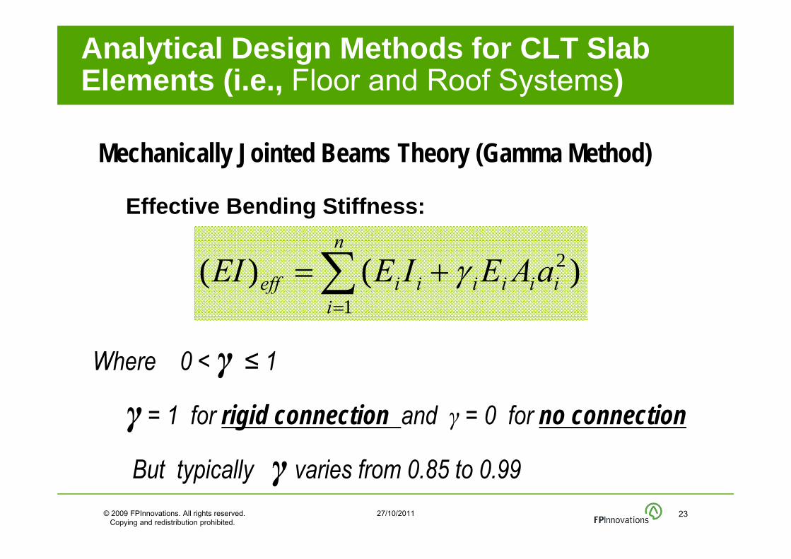
1) Mechanically Jointed Beams Theory (Gamma Method)
– Most common approach in Europe– Based on Annex B of Eurocode 5 (EN 1995:2004)– Developed for beams connected together with
mechanical fasteners with stiffness k uniformly spaced at a certain distance s
– Only layers acting in the direction of loading are used– For L/d ratio ≥ 30, shear deformation of longitudinal
layers is neglected
Analytical Design Methods for CLT Slab Elements (i.e., Floor and Roof Systems)
Fastener (k)

© 2009 FPInnovations. All rights reserved. Copying and redistribution prohibited.
27/10/2011 21
Mechanically Jointed Beams Theory (Gamma Method)
– Method takes into account the rolling shear stiffness (GR) of the cross layers using “imaginary fasteners”
– Longitudinal layers are taken as beam elements connected with “imaginary” fasteners with a
Stiffness = rolling shear stiffness of cross layers
– Recommended for 3 & 5 layers CLT panels– Applied to simply supported beams/panels
Analytical Design Methods for CLT Slab Elements (i.e., Floor and Roof Systems)
© 2009 FPInnovations. All rights reserved. Copying and redistribution prohibited.
27/10/2011 22
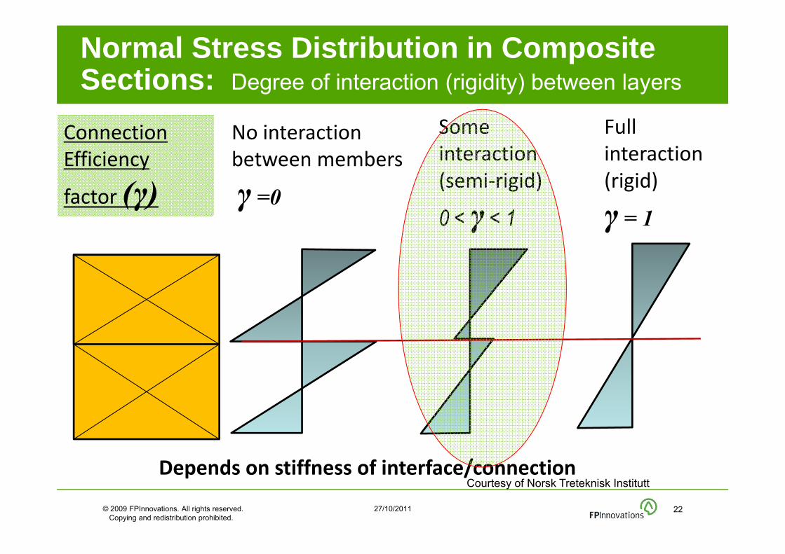
Normal Stress Distribution in Composite Sections: Degree of interaction (rigidity) between layers
No interaction between members
γ =0
Some interaction(semi‐rigid)
0 < γ < 1
Full interaction(rigid)
γ = 1
Courtesy of Norsk Treteknisk InstituttDepends on stiffness of interface/connection
Connection Efficiency
factor (γ)
© 2009 FPInnovations. All rights reserved. Copying and redistribution prohibited.
27/10/2011 23
Mechanically Jointed Beams Theory (Gamma Method)
n
iiiiiiieff aAEIEEI
1
2 )()(
Where 0 < γ ≤ 1
γ = 1 for rigid connection and γ = 0 for no connection
But typically γ varies from 0.85 to 0.99
Effective Bending Stiffness:
Analytical Design Methods for CLT Slab Elements (i.e., Floor and Roof Systems)

© 2009 FPInnovations. All rights reserved. Copying and redistribution prohibited.
27/10/2011 24
2) Composite Theory: K-Method (Blass & Fellmoser)– Based on a theory adopted for plywood but modified– However, stiffness of all layers is used in this case
• Stiffness of cross layers is taken as E90 = E0 / 30– Composition factors (ki) are determined for certain loading
configurations – Effective values of strength and stiffness are calculated
using a composition factor ki
– For L/d ≥ 30, shear deformation is neglected
Analytical Design Methods for CLT Slab Elements (i.e., Floor and Roof Systems)

© 2009 FPInnovations. All rights reserved. Copying and redistribution prohibited.
27/10/2011 25
3) Shear Analogy (Kreuzinger)- Most Precise..
– Consider the different modulus of elasticity and shear modulus of single layers (both directions)
– The effect of shear deformation in both directions is NOT neglected
– Stiffness of cross layers is taken as E90 = E0 / 30
– NOT limited by the No. of layers– Multi-layer CLT panels are considered as two virtual beams A and B
Beam A
Beam B
Analytical Design Methods for CLT Slab Elements (i.e., Floor and Roof Systems)

© 2009 FPInnovations. All rights reserved. Copying and redistribution prohibited.
27/10/2011 26
3) Shear Analogy (Kreuzinger)
n
iiii
n
i
iiiBAeff zAEhbEEIEIEI
1
2
1
3
12)()()(
bGh
bGh
bGh
aGA
n
nn
i ii
ieff
22
)(1
21
1
2
Analytical Design Methods for CLT Slab Elements (i.e., Floor and Roof Systems)
Beam A Beam B

Proposed CLT Standard for North America
A harmonized CLT draft product standard developed by ANSI/APA CLT Standard Committee “Standard for Performance Rated CLT ANSI/APA PRG 320”
5 stress grades for Canada & 7 grades for the US Shear Analogy method has been adopted Properties are given for major and minor axis of the panel
18/10/2011 27

© 2009 FPInnovations. All rights reserved. Copying and redistribution prohibited.
27/10/2011 28
4) Simplified Design Methods – Based on CSA O86
Factored Bending Capacity:
tot
effbr hEEI
FM5.01)(
1
tot
effbr h
IFM
5.0
For E1=E2=E3 (longitudinal layers)
Analytical Design Methods for CLT Slab Elements (i.e., Floor and Roof Systems)

© 2009 FPInnovations. All rights reserved. Copying and redistribution prohibited.
27/10/2011 29
CLT wall elements under combined axial in-plane & out-of-plane loads
1) Theory of Mechanically Jointed Columns (Eurocode 5)
2) CSA O86-09 Approach Combined with Mechanically Connected Beams Theory
Proposed Analytical Design Methods for CLT Wall Elements

© 2009 FPInnovations. All rights reserved. Copying and redistribution prohibited.
27/10/2011 30
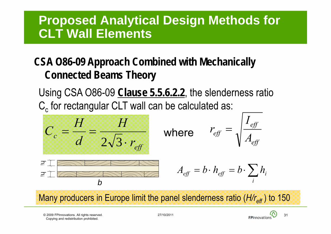
CSA O86-09 Approach Combined with Mechanically Connected Beams Theory
Only the layers oriented parallel to the axial force carry the load
Proposed Analytical Design Methods for CLT Wall Elements
© 2009 FPInnovations. All rights reserved. Copying and redistribution prohibited.
27/10/2011 31
CSA O86-09 Approach Combined with Mechanically Connected Beams Theory
Using CSA O86-09 Clause 5.5.6.2.2, the slenderness ratio Cc for rectangular CLT wall can be calculated as:
effc r
HdHC
32 eff
effeff A
Ir where
i
ieffeff hbhbAb
Many producers in Europe limit the panel slenderness ratio (H/reff ) to 150
Proposed Analytical Design Methods for CLT Wall Elements
© 2009 FPInnovations. All rights reserved. Copying and redistribution prohibited.
27/10/2011 32
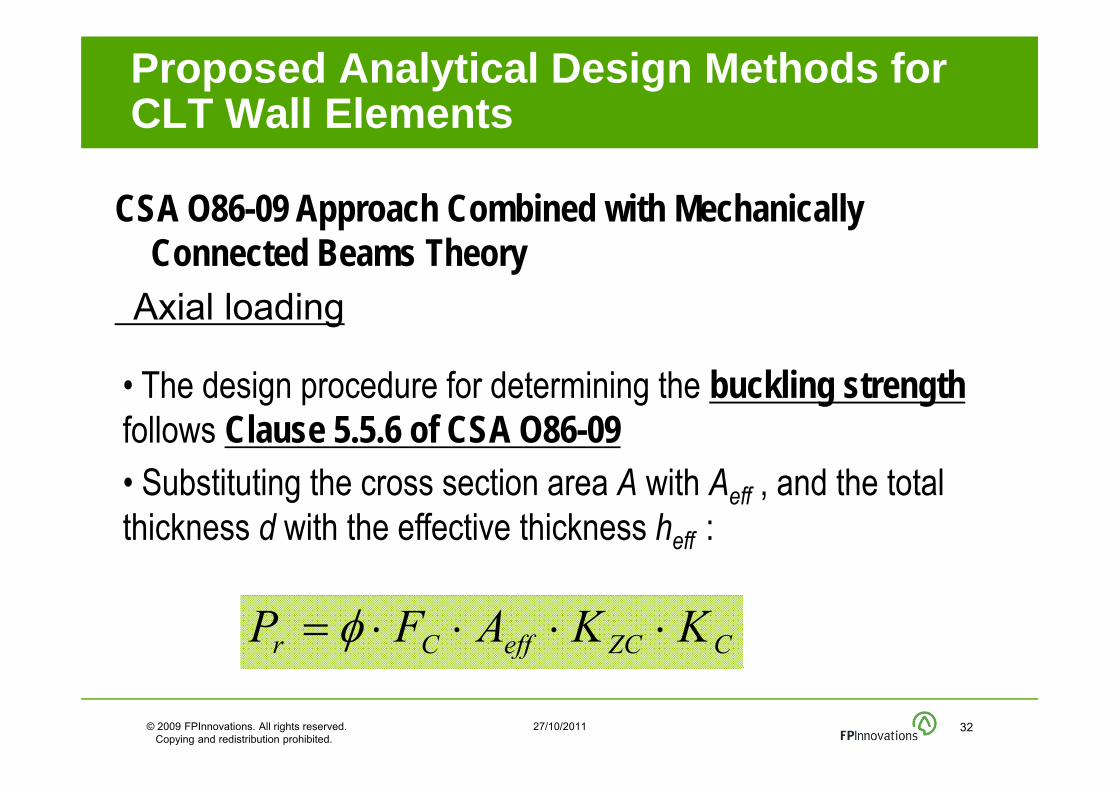
CSA O86-09 Approach Combined with Mechanically Connected Beams Theory
Axial loading
• The design procedure for determining the buckling strength follows Clause 5.5.6 of CSA O86-09 • Substituting the cross section area A with Aeff , and the total thickness d with the effective thickness heff :
CZCeffCr KKAFP
Proposed Analytical Design Methods for CLT Wall Elements

© 2009 FPInnovations. All rights reserved. Copying and redistribution prohibited.
27/10/2011 33
CSA O86-09 Approach Combined with Mechanically Connected Beams Theory
Axial and out of plane/P-∆ effect
Resistance can be determined as per Section 5.5.10 of CSA O86-09:
1,2
r
Pf
r
f
MM
PP
Proposed Analytical Design Methods for CLT Wall Elements
© 2009 FPInnovations. All rights reserved. Copying and redistribution prohibited.
27/10/2011 34
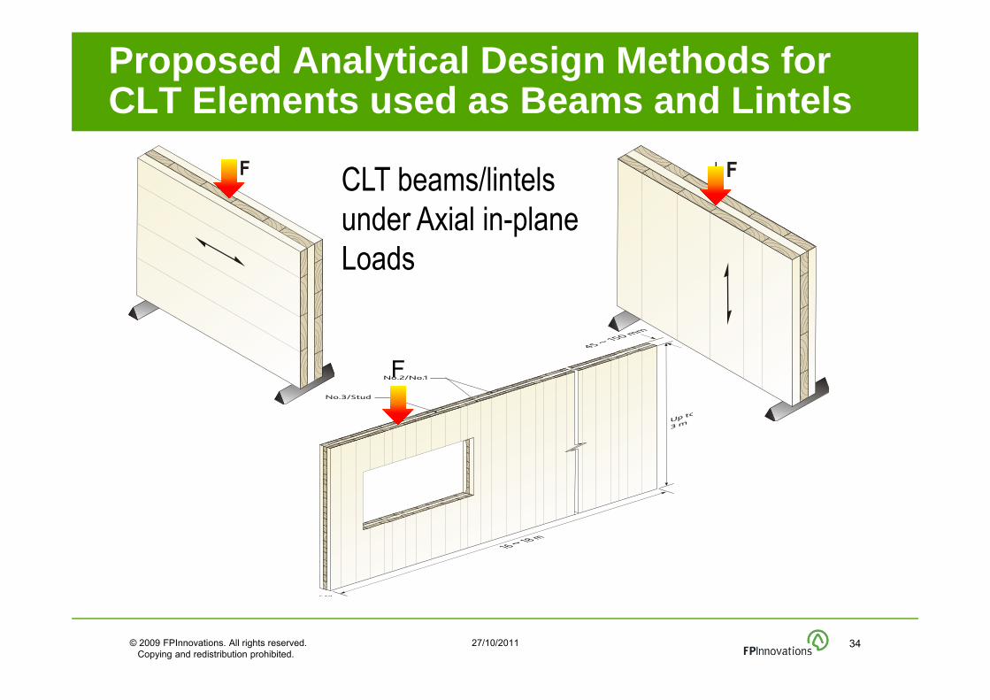
Proposed Analytical Design Methods for CLT Elements used as Beams and Lintels
CLT beams/lintels under Axial in-plane Loads
F
© 2009 FPInnovations. All rights reserved. Copying and redistribution prohibited.
27/10/2011 35
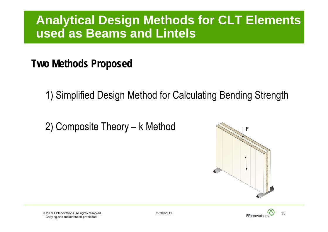
Two Methods Proposed
1) Simplified Design Method for Calculating Bending Strength
2) Composite Theory – k Method
Analytical Design Methods for CLT Elements used as Beams and Lintels

© 2009 FPInnovations. All rights reserved. Copying and redistribution prohibited.
27/10/2011 36
Proposed Analytical Design Methods for CLT Elements used as Beams and Lintels
When the modulus of elasticity of all longitudinal layers areequal (i.e., E1 = E2, etc..)
HI
FM effbr 5.0
Simplified Design Method

© 2009 FPInnovations. All rights reserved. Copying and redistribution prohibited.
27/10/2011 37
Simplified Design Method
H
ii
effeff hHHhI
1212
33
Proposed Analytical Design Methods for CLT Elements used as Beams and Lintels

© 2009 FPInnovations. All rights reserved. Copying and redistribution prohibited.
27/10/2011 38
Load Duration Factor KD
Service Condition Factor KS
System Factor KH
Treatment Factor KT
Lateral Stability Factor KL (beams and lintels)
Size Factor for Bending KZb
Strength Adjustment Factors in CSA O86-09
February 08, 2011 39
Typically, creep rupture is attributed to the load duration effect.
Recommendations are to use those given for lumber & glulam in Table 4.3.2.2, CSA O86-09
Load Duration Factor (KD)
Strength Adjustment Factors in CSA O86-09

February 08, 2011 40
Service Condition Factor (KS)
Different adjustment factors for different mechanical properties
DRY or WET conditions(Dry: Avg. EMC ≤ 15% & MC < 19%)
Recommendations to use Ks for glulam as given in Table 6.4.2, CSA O86-09
Strength Adjustment Factors in CSA O86-09

Shake Table Tests on CLT Assemblies
•Coupled CLT Walls
•Single storey •3-storey building
Seismic Performance of CLT Assemblies

© 2009 FPInnovations. All rights reserved. Copying and redistribution prohibited.
27/10/2011
IVALSA SOFIE Project7-Storeys High CLT Building on a Shake Table
Seismic Performance of CLT Assemblies
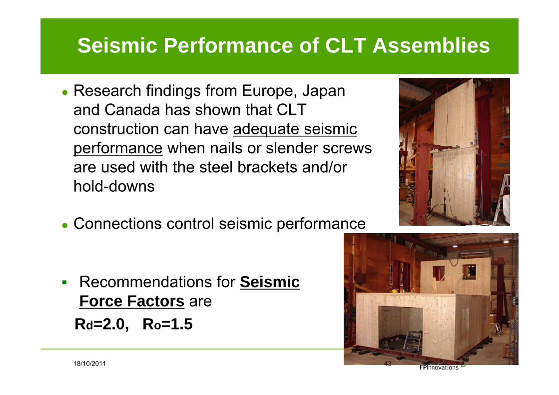
Recommendations for Seismic Force Factors are
Rd=2.0, Ro=1.5
18/10/2011 43
● Research findings from Europe, Japan and Canada has shown that CLT construction can have adequate seismic performance when nails or slender screws are used with the steel brackets and/or hold-downs
● Connections control seismic performance

© 2009 FPInnovations. All rights reserved. Copying and redistribution prohibited.
27/10/2011
Maintain structural integrity
Provide ductility for lateral load design (e.g., seismic & wind)
Affect the serviceability design (vibration, acoustics, etc.)
May affect the fire safety design
Importance of Connections in CLT AssembliesImportance of Connections in CLT Assemblies

Source: M. Augustin /ITE
18/10/2011 45
Common Connection Techniques in CLT

Current CLT Connections Practice in Europe
CarpentryUsing CNC technology to create various types of interlocking profiles (Dovetail connections)
•Source: G. Traetta
● Traditional fastenersBearing or dowel type fasteners, i.e., nails, wood screws, lag screws & bolts, in combination with metal plates, brackets and ties.
● InnovativeSelf-tapping screws & dowels, glued in rods, bearing-type systems, metal hooks, etc.
Source: SFSIntec

© 2009 FPInnovations. All rights reserved. Copying and redistribution prohibited.
27/10/2011
•Wood and Self-Tapping Screws
Extensively used in Europe
Easy to install & provide high lateral & withdrawal capacity
Come in a variety of sizes and features
- Diameters from 4mm to 12mm
- Lengths up to 600mm
Do not require predrilling in most cases, (unlike traditional lag screws)
Used for WW or WS connections
Source: Log &Timber Connections
Source: SFSIntec
Source: Kevin MeechanCourtesy WoodWorks

•© 2009 FPInnovations. All rights reserved. • Copying and redistribution prohibited.
•27/10/2011
CLT Panel to Panel Connection DetailsTraditional Fasteners (Screws, Nails)
Single surface splineSource: G. Traetta
Half-lapped
Double surface splineSingle Internal spline

•© 2009 FPInnovations. All rights reserved. • Copying and redistribution prohibited.
•27/10/2011
CLT Panel to Panel Connection DetailsTraditional Fasteners (Screws, Nails)
Double internal spline
Source: Kevin MeechanCourtesy WoodWorks

•© 2009 FPInnovations. All rights reserved. • Copying and redistribution prohibited.
•27/10/2011
Innovative Systems for CLT Panel to Panel Connections
Tube connection system
(Source:Traetta & Schickhofer , TU of Graz)
Hook type of connection system
© 2009 FPInnovations. All rights reserved. Copying and redistribution prohibited.
27/10/2011
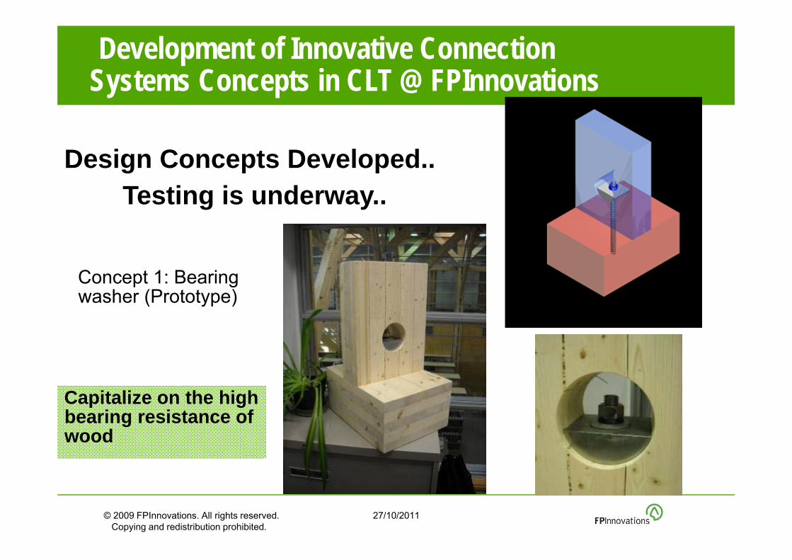
•Development of Innovative Connection Systems Concepts in CLT @ FPInnovations
Design Concepts Developed.. Testing is underway..
Capitalize on the high bearing resistance of wood
Concept 1: Bearing washer (Prototype)

© 2009 FPInnovations. All rights reserved. Copying and redistribution prohibited.
27/10/2011
•Development of Innovative Connection Systems Concepts in CLT
Adopting CNC technology & allow for quick assembly/disassembly
Reduce to steel-to-steel connections
Concept 2
Concept 5
Concept 3Concept 4

www.fpinnovations.ca
Structural Performance and Design of CLT Building
™
© 2010 FPInnovations. All rights reserved. Copying and redistribution prohibited. ™ FPInnovations, its marks and logos are trademarks of FPInnovations.
Sylvain Gagnon, Eng.M. Mohammad, Ph.D., P.Eng.