Embed Size (px)
Citation preview

3/9/07 , 9/11/15
Note: Always refer to winding diagram and user manuals set shipped with the Insulgard
Installation Guidelines Installation of the InsulGard system is based on the physical layout of each installation. Therefore, there is no such thing as a “Standard installation”. Each installation will be unique. In any event, we provide the following guidelines. A typical Installation will require the following. Please refer to the attached sketch for reference and recommended wire and conduit sizes. 1. Mount the InsulGard enclosure as close to the machine as possible. The maximum
distance allowed between the sensors and the InsulGard (cables length) is ~150 feet. 2. The InsulGard for 115VAC application requires 1.0 Amp for power. We ask a 10 Amp
service since we have a for 115 volt outlet in the enclosure. The InsulGard for 230VAC application requires only 1.0 Amp for power since the outlet isn’t installed.
3. Outputs from the InsulGard are as follows and appropriate conduit and wiring is required
based on customer desires.
• Dry Contact indicating the Status of the monitor
• Dry Contact for both the Warning and Alarm indication
• 4-20 ma signal that is proportional to PD activity
• RS 485 output for networking and/or remote communication
4. Inputs for the InsulGard are as follows:
• 15 channels for PD signals
• 1 channel for noise cancellation (rarely used)
• Temperature sensor Input (RTD)
• Humidity sensor Input
• Load Current Input

Step By Step Installation Guideline
This document is being provided to be used as a guideline. Refer to the included user and installation manuals for more detailed instructions. Sample installation pictures are also included.
1) Determine best location and install the InsulGard enclosure
a) As close to the motor termination box as possible b) On same side of machine as the RTD Termination Box c) Other Considerations
i) Access to main power (115/230 volts AC) ii) Interface point to the plant control and monitoring system for the dry contacts, 4-
20 ma output, RS-485 network, Modem connection BRING RELIABLE GROUND TO EXTERNAL GROUNDING BOLT ON INSULGARD ENCLOSURE.
2) Install Coupling Capacitors Be sure to install the capacitors on the HV Phase leads and not on the neutral side of the winding. a) Installed in motor termination box. b) Connected phase to ground c) Supplied HV cable should be kept as short as possible to keep the circuit impedance
as low as possible d) If motor has surge capacitors, install the HV connection on the motor winding side of
the surge capacitors. See diagrams below.
MotorWinding
CouplingCap
SurgeCap
Inco
min
gP
ow
er
Right
MotorWinding
Inc
om
ing
Po
we
r
CouplingCap
SurgeCap
Wrong
Motor
Winding
Coupling
Cap
Surge
Cap
Inco
min
g
Po
wer
Wrong
e) Install the Coupling Capacitor connected to Channel #1 on phase A. f) If RFCT used instead of IPDS sensors look for the corresponding manuals
3) Install the Dynamic Sensors in the motor termination box a) Humidity

b) Load Current Sensor. This sensor goes around the secondary connection of the motor primary current transformer. This option is possible only in case if metering CTs are installed over the motor leads in the feeder connection box. Differential CTs are not applicable for load current monitoring.
c) I there are no metering CTs use auxiliary FlexCore CT installed over shielded part of incoming feeder.
d) Air Temperature external RTD sensor if supplied and no winding temperature RTD is available. General approach for temperature metering: should represent winding temperature as close as possible. Using one of the winding RTDs is preferable, next options are RTD in hot air, then external Temperature sensor somewhere inside motor volume and the last one is feeder termination box next to Humidity sensor.
e) NOTE: Make sure wires are not near any high voltage source. Do not use "sticky pad" type of tie downs!!
4) Wire between the Motor Terminal Box and the InsulGard
a) Three Coax Wires from the Coupling Capacitors b) One 3 conductor 22 AWG shielded cable for the humidity sensor c) One 2 conductor 22 AWG shielded cable for the load current sensor d) One 3 conductor 22 AWG shielded cable for the air temperature RTD if provided
5) Install RTD PD Module a) Verify if the existing RTD termination box at the Motor frame is large enough to install
the RTD module. Most RTD termination boxes are large enough to accommodate the RTD Module. The RTD Module is 7 inches long and 1.75 inches wide and 1 inch high.
b) The RTD module goes in series with the existing RTD wiring. c) Many times the existing RTD terminal board can be removed and the RTD module
inserted in its place. d) If the existing RTD termination box is not large enough an auxiliary box will need to
be installed next to existing to house the RTD Module and wired in appropriately.
6) Run wires between RTD module and the InsulGard a) Six coax cables (12 if 2 modules are supplied for 12 RTDs) b) One 3 conductor 22 AWG shielded cable from a spare or provided winding RTD.
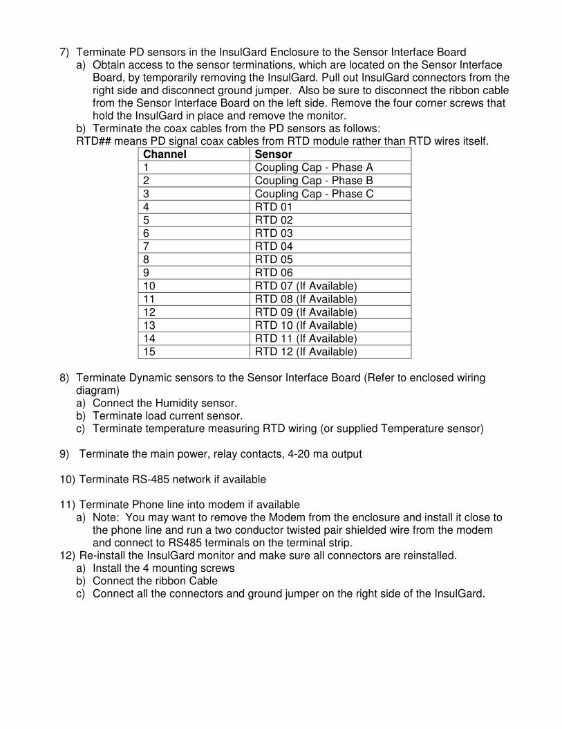
7) Terminate PD sensors in the InsulGard Enclosure to the Sensor Interface Board
a) Obtain access to the sensor terminations, which are located on the Sensor Interface Board, by temporarily removing the InsulGard. Pull out InsulGard connectors from the right side and disconnect ground jumper. Also be sure to disconnect the ribbon cable from the Sensor Interface Board on the left side. Remove the four corner screws that hold the InsulGard in place and remove the monitor.
b) Terminate the coax cables from the PD sensors as follows: RTD## means PD signal coax cables from RTD module rather than RTD wires itself.
Channel Sensor 1 Coupling Cap - Phase A 2 Coupling Cap - Phase B
3 Coupling Cap - Phase C 4 RTD 01 5 RTD 02 6 RTD 03 7 RTD 04 8 RTD 05 9 RTD 06
10 RTD 07 (If Available) 11 RTD 08 (If Available) 12 RTD 09 (If Available) 13 RTD 10 (If Available) 14 RTD 11 (If Available) 15 RTD 12 (If Available)
8) Terminate Dynamic sensors to the Sensor Interface Board (Refer to enclosed wiring
diagram) a) Connect the Humidity sensor. b) Terminate load current sensor. c) Terminate temperature measuring RTD wiring (or supplied Temperature sensor)
9) Terminate the main power, relay contacts, 4-20 ma output 10) Terminate RS-485 network if available 11) Terminate Phone line into modem if available
a) Note: You may want to remove the Modem from the enclosure and install it close to the phone line and run a two conductor twisted pair shielded wire from the modem and connect to RS485 terminals on the terminal strip.
12) Re-install the InsulGard monitor and make sure all connectors are reinstalled. a) Install the 4 mounting screws b) Connect the ribbon Cable c) Connect all the connectors and ground jumper on the right side of the InsulGard.

Typical Insulgard/Sensors configuration
IPDS
A phase line terminal
CT sensor
Existing wires
to temperature
measuringdevice
CT secondary
winding output
Temperaturesensor
Humiditysensor
3-wires cables toInsulGard Terminal strip
(contacts 1, 2 & 3)
Metering CT
Existing wiresfrom RTD in
stator winding
3 coax. cables to
InsulGard Sensor
Interface board.
IPDSIPDS
C phase line terminal
B phase line terminal
2-wires cable toInsulGard
Terminal strip
(contacts 4 & 5).
Motor
Motor connection box
RTD PD Sensor
Board
RTD connection box
To Ch 1
To Ch 2
To Ch 3
3-wires cables toInsulGard Terminal strip
(contacts 6, 7 & 8)
6 coax cables to
InsulGard SensorInterface board.
RTD PD sensor
output
Input of Insulgard
Sensor Interface
board
PD 1 Ch 4
PD 2 Ch 5
PD 3 Ch 6
PD 4 Ch 7
PD 5 Ch 8
PD 6 Ch 9

Typical connection diagram
There is no outlet for 230VAC application.
Fuse inside InsulGard for 115VAC application:Time-Lag 200mA, 250VAC, 5X20mm type 5ST by BEL Fuse Inc.,Catalog # 5ST 200.
Fuse inside InsulGard for 230VAC application:Time-Lag 100mA, 250VAC, 5X20mm type 5ST by BEL Fuse Inc.,
Catalog # 5ST 100.
Fuse on the panel: Fast Acting 3.0A, 250VAC, 5x20mm type 5MF by Bel Fuse Inc. Catalog # 5MF 3-R (or equivalent).
3
InsulGard Panel Wiring Diagram Connection to:
Co
nn
ecto
r fo
r F
lat
Cab
le f
rom
Insu
lGard
Co
ax
ca
ble
s f
rom
PD
Se
ns
ors
Ch1
Ch 2
Ch 4
Ch 3
Ch 5
Ch 6
Ch 8
Ch 7
Ch 9
Ch 10
Ch 12
Ch 11
Ch 13
Ch 14
Ch 16(Noise)
Ch 15
Sen
so
r In
terf
ace
Bo
ard
RTD
CT
H%
S
+5
S
Ref
5
S1
S2
6
7
8
9
10
11
12
4
3
2
1
Signal
Shield
H% RefSw
Ground Screw
on the panel
Ground screw on enclosuremust be connected to local
ground
red
white
white
white
red
black
black
black
Humidity sensor
CT - Load sensor
Temperature sensor
Auxiliary sensor
connection:
green
Power 115VACN
eu
tral
Gro
un
d
Ph
as
e
1
InsulGard'sconnectors
Fla
t C
ab
le
toS
en
so
r In
terf
ace B
oard
Ala
rmW
arn
ing
+
4-2
0m
AA
larm
2
GL
N
Po
we
r
-+
5G
BA
RS
- 4
85
Sta
tus
Ala
rm 1
DIN-Rail Terminals
Eth
ern
et
Dev
ice
Ho
st
US
BU
SB
4-20 mA interface
RS485 interface
Alarm relay
Warning relay
Status relay
greenG
ree
nredwhite
Screw onback cover 2
Leftside
Rightside
N
L
Gn
d
Gn
d
Fu
se
Outlet
Note: For actual installation use the wiring diagram supplied with each InsulGard. InsulGard must be grounded at the place of installation.

Typical InsulGard connections for motors:
InsulGard EnclosureNEMA 4
Note:Mount close to a motor mainterminal box and RTDtermination box to minimizecable and conduits length
120 (230) VAC
10 amp
Power Source
1 - 2 conductor, twisted pair 22 AWG for RS485 Networkand/or 1- 2 conductor phone wire for modem remotecommunications, if required.1 - 2 conductor shielded wire for 4 - 20 ma output, if required
1 - 6 conductor cable suitable monitoring of dry contacts forsystem status, low alarm and high alarm (minimum 2conductors if contacts are connected in series or in parallel)
1" conduit
fitting
1 1/2"
conduit
fitting
Motor terminal box
3 coax cables from couplingcapacitors1 - 3 wire shielded cableAWG22 for Humidity sensor(comes with the sensor)1 - 2 wire shielded cableAWG22 for Load sensor(comes with the sensor)1 - 3 wire shielded cableAWG22 for the Temperaturesensor (if provided, comeswith the sensor)
RTD terminal box
1 coax cable per RTDfrom RTD PD sensor(s)1 - 3 wire shielded cableAWG22 for winding RTD(if provided)

Insulgard assembled into NEMA-4 enclosure
Back panel with PD sensor coax cables connected

Coupling Capacitor Installations
Humidity senor location

RTD sensor Installations RTD Modules Installed in Series with Existing wiring. Many times we replace the exiting terminal block with this sensor. Each RTD Module is good for 6 RTDs.
RTD junction box before RTD module installation After. Spare RTD used for temperature monitoring
RTD junction box before RTD module installation After
Extra box for RTD module Replacing part of DIN rail terminal strip with RTD
module

Monitor installation
Note: If conduit is installed on the top of the enclosure, be sure to use appropriate seals,
etc to prevent the entrance of water.
Placing FlexCore CT with current sensor on shorted CT secondary wire. Current sensor can be used over metering CT secondary
wire if have such CTs in feeder termination box