Embed Size (px)
Citation preview

TABLE OF CONTENTS
1.0 INTRODUCTION . . . . . . . . . . . . . . . . . . . . . . . . . . . . . . . . . . . . . . . . . . . . . . . . . . . . . . . . .1
1.1 SYSTEM COVERAGE . . . . . . . . . . . . . . . . . . . . . . . . . . . . . . . . . . . . . . . . . . . . . . .11.2 SIX -STEP TROUBLESHOOTING PROCEDURE. . . . . . . . . . . . . . . . . . . . . . . . . .1
2.0 IDENTIFICATION OF SYSTEM . . . . . . . . . . . . . . . . . . . . . . . . . . . . . . . . . . . . . . . . . . . . .1
3.0 SYSTEM DESCRIPTION AND FUNCTIONAL OPERATION . . . . . . . . . . . . . . . . . . . . . .1
3.1 GENERAL DESCRIPTION . . . . . . . . . . . . . . . . . . . . . . . . . . . . . . . . . . . . . . . . . . . .13.2 FUNCTIONAL OPERATION . . . . . . . . . . . . . . . . . . . . . . . . . . . . . . . . . . . . . . . . . . .2
3.2.1 TRANSMISSION OPERATION AND SHIFT SCHEDULING ATVARIOUS OIL TEMPERATURES . . . . . . . . . . . . . . . . . . . . . . . . . . . . . . .2
3.2.2 LINE PRESSURE CONTROL. . . . . . . . . . . . . . . . . . . . . . . . . . . . . . . . . .33.2.3 DRIVE LEARN PROCEDURE . . . . . . . . . . . . . . . . . . . . . . . . . . . . . . . . .4
3.3 DIAGNOSTIC TROUBLE CODES . . . . . . . . . . . . . . . . . . . . . . . . . . . . . . . . . . . . . .53.3.1 HARD CODE . . . . . . . . . . . . . . . . . . . . . . . . . . . . . . . . . . . . . . . . . . . . . . .63.3.2 ONE TRIP FAILURES. . . . . . . . . . . . . . . . . . . . . . . . . . . . . . . . . . . . . . . .63.3.3 INTERMITTENT CODE. . . . . . . . . . . . . . . . . . . . . . . . . . . . . . . . . . . . . . .63.3.4 STARTS SINCE SET COUNTER. . . . . . . . . . . . . . . . . . . . . . . . . . . . . . .63.3.5 TROUBLE CODE ERASURE . . . . . . . . . . . . . . . . . . . . . . . . . . . . . . . . . .63.3.6 LIST OF DIAGNOSTIC TROUBLE CODES (DTC) (Detailed
descriptions follow list) . . . . . . . . . . . . . . . . . . . . . . . . . . . . . . . . . . . . . . .73.3.7 DTC DESCRIPTIONS . . . . . . . . . . . . . . . . . . . . . . . . . . . . . . . . . . . . . . . .83.3.8 QUICK LEARN . . . . . . . . . . . . . . . . . . . . . . . . . . . . . . . . . . . . . . . . . . . .193.3.9 CLUTCH VOLUMES . . . . . . . . . . . . . . . . . . . . . . . . . . . . . . . . . . . . . . . .20
3.4 USING THE DRBIIIT . . . . . . . . . . . . . . . . . . . . . . . . . . . . . . . . . . . . . . . . . . . . . . . .203.5 DRBIIIT ERROR MESSAGES . . . . . . . . . . . . . . . . . . . . . . . . . . . . . . . . . . . . . . . .20
3.5.1 DRBIIIT DOES NOT POWER UP (BLANK SCREEN). . . . . . . . . . . . . .203.5.2 DISPLAY IS NOT VISIBLE . . . . . . . . . . . . . . . . . . . . . . . . . . . . . . . . . . .203.5.3 SOME DISPLAY ITEMS READ 9---9. . . . . . . . . . . . . . . . . . . . . . . . . . . .20
3.6 TRANSMISSION SIMULATOR (MILLER TOOL # 8333). . . . . . . . . . . . . . . . . . . .214.0 DISCLAIMERS, SAFETY, AND WARNINGS . . . . . . . . . . . . . . . . . . . . . . . . . . . . .214.1 DISCLAIMERS. . . . . . . . . . . . . . . . . . . . . . . . . . . . . . . . . . . . . . . . . . . . . . . . . . . . .214.2 SAFETY . . . . . . . . . . . . . . . . . . . . . . . . . . . . . . . . . . . . . . . . . . . . . . . . . . . . . . . . . .21
4.2.1 TECHNICIAN SAFETY INFORMATION. . . . . . . . . . . . . . . . . . . . . . . . .214.2.2 VEHICLE PREPARATION FOR TESTING . . . . . . . . . . . . . . . . . . . . . .214.2.3 SERVICING SUB-ASSEMBLIES . . . . . . . . . . . . . . . . . . . . . . . . . . . . . .214.2.4 DRBIIIT SAFETY INFORMATION . . . . . . . . . . . . . . . . . . . . . . . . . . . . .22
4.3 WARNINGS . . . . . . . . . . . . . . . . . . . . . . . . . . . . . . . . . . . . . . . . . . . . . . . . . . . . . . .224.3.1 VEHICLE DAMAGE WARNINGS . . . . . . . . . . . . . . . . . . . . . . . . . . . . . .224.3.2 ROAD TESTING A COMPLAINT VEHICLE. . . . . . . . . . . . . . . . . . . . . .224.3.3 ELECTRONIC PINION FACTOR WARNINGS (IF APPLICABLE) . . . .234.4.4 BULLETINS AND RECALLS. . . . . . . . . . . . . . . . . . . . . . . . . . . . . . . . . .23
5.0 REQUIRED TOOLS AND EQUIPMENT . . . . . . . . . . . . . . . . . . . . . . . . . . . . . . . . . . . . .23
6.0 GLOSSARY OF TERMS . . . . . . . . . . . . . . . . . . . . . . . . . . . . . . . . . . . . . . . . . . . . . . . . . .23
6.1 ACRONYMS . . . . . . . . . . . . . . . . . . . . . . . . . . . . . . . . . . . . . . . . . . . . . . . . . . . . . .236.2 DEFINITIONS . . . . . . . . . . . . . . . . . . . . . . . . . . . . . . . . . . . . . . . . . . . . . . . . . . . . .24
i

TABLE OF CONTENTS - Continued
7.0 DIAGNOSTIC INFORMATION AND PROCEDURES . . . . . . . . . . . . . . . . . . . . . . . . . . .25
COMMUNICATION*NO RESPONSE FROM TRANSMISSION CONTROL MODULE - GAS ONLY . . . . . .26
TRANSMISSIONP0120-THROTTLE POSITION SENSOR SIGNAL CIRCUIT . . . . . . . . . . . . . . . . . . . . .29P0218-HIGH TEMPERATURE OPERATION ACTIVATED . . . . . . . . . . . . . . . . . . . . . . .32P0604-INTERNAL TCM . . . . . . . . . . . . . . . . . . . . . . . . . . . . . . . . . . . . . . . . . . . . . . . . . .34P0605-INTERNAL TCM . . . . . . . . . . . . . . . . . . . . . . . . . . . . . . . . . . . . . . . . . . . . . . . . . .35P0613-INTERNAL TCM . . . . . . . . . . . . . . . . . . . . . . . . . . . . . . . . . . . . . . . . . . . . . . . . . .36P0706-CHECK SHIFTER SIGNAL . . . . . . . . . . . . . . . . . . . . . . . . . . . . . . . . . . . . . . . . . .37P0715-INPUT SPEED SENSOR ERROR . . . . . . . . . . . . . . . . . . . . . . . . . . . . . . . . . . . .45P0720-OUTPUT SPEED SENSOR ERROR . . . . . . . . . . . . . . . . . . . . . . . . . . . . . . . . . .49P0725-ENGINE SPEED SENSOR CIRCUIT . . . . . . . . . . . . . . . . . . . . . . . . . . . . . . . . . .53P0731-GEAR RATIO ERROR IN 1ST . . . . . . . . . . . . . . . . . . . . . . . . . . . . . . . . . . . . . . .56P0732-GEAR RATIO ERROR IN 2ND . . . . . . . . . . . . . . . . . . . . . . . . . . . . . . . . . . . . . . .58P0733-GEAR RATIO ERROR IN 3RD . . . . . . . . . . . . . . . . . . . . . . . . . . . . . . . . . . . . . . .61P0734-GEAR RATIO ERROR IN 4TH . . . . . . . . . . . . . . . . . . . . . . . . . . . . . . . . . . . . . . .64P0735-GEAR RATIO ERROR 4TH PRIME . . . . . . . . . . . . . . . . . . . . . . . . . . . . . . . . . . .66P0736-GEAR RATIO ERROR IN REVERSE. . . . . . . . . . . . . . . . . . . . . . . . . . . . . . . . . .68P0740-TORQUE CONVERTER CLUTCH CONTROL CIRCUIT. . . . . . . . . . . . . . . . . . .70P0750-LR SOLENOID CIRCUIT. . . . . . . . . . . . . . . . . . . . . . . . . . . . . . . . . . . . . . . . . . . .72P0755-2C SOLENOID CIRCUIT. . . . . . . . . . . . . . . . . . . . . . . . . . . . . . . . . . . . . . . . . . . .76P0760-OD SOLENOID CIRCUIT . . . . . . . . . . . . . . . . . . . . . . . . . . . . . . . . . . . . . . . . . . .80P0765-UD SOLENOID CIRCUIT . . . . . . . . . . . . . . . . . . . . . . . . . . . . . . . . . . . . . . . . . . .84P0770-4C SOLENOID CIRCUIT. . . . . . . . . . . . . . . . . . . . . . . . . . . . . . . . . . . . . . . . . . . .88P0841-LR PRESSURE SWITCH SENSE CIRCUIT . . . . . . . . . . . . . . . . . . . . . . . . . . . .92P0845-2C HYDRAULIC PRESSURE TEST FAILURE . . . . . . . . . . . . . . . . . . . . . . . . . .96P0846-2C PRESSURE SWITCH SENSE CIRCUIT . . . . . . . . . . . . . . . . . . . . . . . . . . .102P0867-LINE PRESSURE FAULT . . . . . . . . . . . . . . . . . . . . . . . . . . . . . . . . . . . . . . . . . .106P0868-LINE PRESSURE LOW . . . . . . . . . . . . . . . . . . . . . . . . . . . . . . . . . . . . . . . . . . .109P0869-LINE PRESSURE HIGH . . . . . . . . . . . . . . . . . . . . . . . . . . . . . . . . . . . . . . . . . . .114P0870-OD HYDRAULIC PRESSURE TEST FAILURE . . . . . . . . . . . . . . . . . . . . . . . . .119P0871-OD PRESSURE SWITCH SENSE CIRCUIT . . . . . . . . . . . . . . . . . . . . . . . . . . .125P0875-UD HYDRAULIC PRESSURE TEST FAILURE . . . . . . . . . . . . . . . . . . . . . . . . .129P0876-UD PRESSURE SWITCH SENSE CIRCUIT . . . . . . . . . . . . . . . . . . . . . . . . . . .135P0884-POWER UP AT SPEED . . . . . . . . . . . . . . . . . . . . . . . . . . . . . . . . . . . . . . . . . . .139P0888-RELAY OUTPUT ALWAYS OFF . . . . . . . . . . . . . . . . . . . . . . . . . . . . . . . . . . . . .140P0890-SWITCHED BATTERY . . . . . . . . . . . . . . . . . . . . . . . . . . . . . . . . . . . . . . . . . . . .144P0891-TRANSMISSION RELAY ALWAYS ON . . . . . . . . . . . . . . . . . . . . . . . . . . . . . . .148P0932-LINE PRESSURE SENSOR FAULT. . . . . . . . . . . . . . . . . . . . . . . . . . . . . . . . . .151P0944-LOSS OF PRIME. . . . . . . . . . . . . . . . . . . . . . . . . . . . . . . . . . . . . . . . . . . . . . . . .155P0987-4C HYDRAULIC PRESSURE TEST FAILURE . . . . . . . . . . . . . . . . . . . . . . . . .158P0988-4C PRESSURE SWITCH SENSE CIRCUIT . . . . . . . . . . . . . . . . . . . . . . . . . . .164P1684-BATTERY WAS DISCONNECTED . . . . . . . . . . . . . . . . . . . . . . . . . . . . . . . . . . .168P1694-BUS COMMUNICATION WITH ENGINE MODULE. . . . . . . . . . . . . . . . . . . . . .170P1715-RESTRICTED PORT IN T3 RANGE . . . . . . . . . . . . . . . . . . . . . . . . . . . . . . . . .172P1736-GEAR RATIO ERROR IN 2ND PRIME . . . . . . . . . . . . . . . . . . . . . . . . . . . . . . .173P1775-SOLENOID SWITCH VALVE LATCHED IN TCC POSITION . . . . . . . . . . . . . .175P1776-SOLENOID SWITCH VALVE LATCHED IN LR POSITION. . . . . . . . . . . . . . . .179P1790-FAULT IMMEDIATELY AFTER SHIFT . . . . . . . . . . . . . . . . . . . . . . . . . . . . . . . .183P1793-TRD LINK COMMUNICATION ERROR . . . . . . . . . . . . . . . . . . . . . . . . . . . . . . .184
ii

TABLE OF CONTENTS - Continued
P1794-SPEED SENSOR GROUND ERROR . . . . . . . . . . . . . . . . . . . . . . . . . . . . . . . .187P1799-CALCULATED OIL TEMP IN USE . . . . . . . . . . . . . . . . . . . . . . . . . . . . . . . . . . .190P2700-INADEQUATE ELEMENT VOLUME LR. . . . . . . . . . . . . . . . . . . . . . . . . . . . . . .194P2701-INADEQUATE ELEMENT VOLUME 2C. . . . . . . . . . . . . . . . . . . . . . . . . . . . . . .196P2702-INADEQUATE ELEMENT VOLUME OD . . . . . . . . . . . . . . . . . . . . . . . . . . . . . .198P2703- INADEQUATE ELEMENT VOLUME UD . . . . . . . . . . . . . . . . . . . . . . . . . . . . . .200P2704-INADEQUATE ELEMENT VOLUME 4C. . . . . . . . . . . . . . . . . . . . . . . . . . . . . . .202P2706-MS SOLENOID CIRCUIT . . . . . . . . . . . . . . . . . . . . . . . . . . . . . . . . . . . . . . . . . .204*BACKUP LAMPS COME ON WHILE SHIFTER IS NOT IN REVERSE POSITION. .208*BACKUP LAMPS INOPERATIVE . . . . . . . . . . . . . . . . . . . . . . . . . . . . . . . . . . . . . . . . .209*BUMP FELT SHORTLY AFTER STOP WITH NO DTC’S PRESENT . . . . . . . . . . . . .211*BUMP FELT WHILE COASTING IN NEUTRAL WITH NO DTC’S PRESENT . . . . . .212*CHECKING PARK/NEUTRAL SWITCH OPERATION . . . . . . . . . . . . . . . . . . . . . . . . .213*POOR SHIFT QUALITY . . . . . . . . . . . . . . . . . . . . . . . . . . . . . . . . . . . . . . . . . . . . . . . .215*TRANSMISSION NOISY WITH NO DTC’S PRESENT . . . . . . . . . . . . . . . . . . . . . . . .216*TRANSMISSION SHIFTS EARLY WITH NO DTC’S . . . . . . . . . . . . . . . . . . . . . . . . . .218*TRANSMISSION SHIFTS ROUGH AFTER TCM REPLACEMENT OR REFLASH . .219*TRANSMISSION SIMULATOR WILL NOT POWER UP . . . . . . . . . . . . . . . . . . . . . . .220*VEHICLE IS SLUGGISH WITH NO DTC’S PRESENT . . . . . . . . . . . . . . . . . . . . . . . .221
VERIFICATION TESTSVERIFICATION TESTS. . . . . . . . . . . . . . . . . . . . . . . . . . . . . . . . . . . . . . . . . . . . . . . . . .222
8.0 COMPONENT LOCATIONS . . . . . . . . . . . . . . . . . . . . . . . . . . . . . . . . . . . . . . . . . . . . . .225
8.1 CRANKSHAFT POSITION SENSOR . . . . . . . . . . . . . . . . . . . . . . . . . . . . . . . . . .2258.2 ELECTRONIC MODULE LOCATIONS. . . . . . . . . . . . . . . . . . . . . . . . . . . . . . . . .2258.3 TRANSMISSION COMPONENT LOCATIONS . . . . . . . . . . . . . . . . . . . . . . . . . .2258.4 TRANSMISSION CONTROL MODULE . . . . . . . . . . . . . . . . . . . . . . . . . . . . . . . .2268.5 TRANSMISSION LINE PRESSURE SENSOR . . . . . . . . . . . . . . . . . . . . . . . . . .226
9.0 CONNECTOR PINOUTS . . . . . . . . . . . . . . . . . . . . . . . . . . . . . . . . . . . . . . . . . . . . . . . .227
ACCELERATOR PEDAL POSITION SENSOR (DIESEL) - BLACK 10 WAY. . . . . . . .227BRAKE LAMP SWITCH - GRAY 6 WAY . . . . . . . . . . . . . . . . . . . . . . . . . . . . . . . . . . . .227C113 (DIESEL) - LT. GRAY (TRANSMISSION SIDE) . . . . . . . . . . . . . . . . . . . . . . . . . .227C201 (DIESEL) - WHITE (SHIFTER ASSEMBLY SIDE). . . . . . . . . . . . . . . . . . . . . . . .227CONTROLLER ANTILOCK BRAKE - BLACK 24 WAY . . . . . . . . . . . . . . . . . . . . . . . . .228CRANKSHAFT POSITION SENSOR (GAS) - BLACK 3 WAY . . . . . . . . . . . . . . . . . . .228DATA LINK CONNECTOR - BLACK 16 WAY . . . . . . . . . . . . . . . . . . . . . . . . . . . . . . . .229DIAGNOSTIC JUNCTION PORT - BLACK 16 WAY . . . . . . . . . . . . . . . . . . . . . . . . . . .229ENGINE CONTROL MODULE C1 (DIESEL) - BLACK 81 WAY. . . . . . . . . . . . . . . . . .230ENGINE CONTROL MODULE C2 (DIESEL) - BLACK 40 WAY. . . . . . . . . . . . . . . . . .231GOVERNOR PRESSURE SENSOR . . . . . . . . . . . . . . . . . . . . . . . . . . . . . . . . . . . . . . .231INPUT SPEED SENSOR (4.7L) - BLACK 2 WAY . . . . . . . . . . . . . . . . . . . . . . . . . . . . .232FUSES (JB) . . . . . . . . . . . . . . . . . . . . . . . . . . . . . . . . . . . . . . . . . . . . . . . . . . . . . . . . . . .234JUNCTION BLOCK C2 (LHD) - BLACK 52 WAY . . . . . . . . . . . . . . . . . . . . . . . . . . . . .235JUNCTION BLOCK C2 (RHD) - BLACK 52 WAY . . . . . . . . . . . . . . . . . . . . . . . . . . . . .236JUNCTION BLOCK C3 - BLACK 52 WAY . . . . . . . . . . . . . . . . . . . . . . . . . . . . . . . . . . .237LEFT REAR LAMP ASSEMBLY - BLACK 6 WAY . . . . . . . . . . . . . . . . . . . . . . . . . . . . .238LINE PRESSURE SENSOR (4.7L) - BLACK 4 WAY . . . . . . . . . . . . . . . . . . . . . . . . . .238OUTPUT SPEED SENSOR (4.0L) - GRAY 2 WAY . . . . . . . . . . . . . . . . . . . . . . . . . . . .238OUTPUT SPEED SENSOR (4.7L) - BLACK 2 WAY . . . . . . . . . . . . . . . . . . . . . . . . . . .238
iii

TABLE OF CONTENTS - Continued
PARK/NEUTRAL POSITION SWITCH (4.0L) - BLACK 3 WAY . . . . . . . . . . . . . . . . . .239POWERTRAIN CONTROL MODULE C1 (GAS) - BLACK 32 WAY . . . . . . . . . . . . . . .239POWERTRAIN CONTROL MODULE C2 (GAS) - WHITE 32 WAY . . . . . . . . . . . . . . .240POWERTRAIN CONTROL MODULE C3 (GAS) - GRAY 32 WAY . . . . . . . . . . . . . . . .241FUSES (DIESEL) . . . . . . . . . . . . . . . . . . . . . . . . . . . . . . . . . . . . . . . . . . . . . . . . . . . . . .243BACK-UP LAMP RELAY (DIESEL) . . . . . . . . . . . . . . . . . . . . . . . . . . . . . . . . . . . . . . . .243FUSES (GAS) . . . . . . . . . . . . . . . . . . . . . . . . . . . . . . . . . . . . . . . . . . . . . . . . . . . . . . . . .245TRANSMISSION CONTROL RELAY (GAS) . . . . . . . . . . . . . . . . . . . . . . . . . . . . . . . . .245RIGHT REAR LAMP ASSEMBLY - BLACK 6 WAY. . . . . . . . . . . . . . . . . . . . . . . . . . . .246SHIFTER ASSEMBLY (C201 DIESEL) - WHITE 12 WAY. . . . . . . . . . . . . . . . . . . . . . .246SHIFTER ASSEMBLY (GAS) - WHITE 6 WAY . . . . . . . . . . . . . . . . . . . . . . . . . . . . . . .246SHIFTER ASSEMBLY C1 (DIESEL) - BLACK 12 WAY . . . . . . . . . . . . . . . . . . . . . . . .246SHIFTER ASSEMBLY C2 (DIESEL) - 6 WAY . . . . . . . . . . . . . . . . . . . . . . . . . . . . . . . .247THROTTLE POSITION SENSOR (4.0L) - BLACK 3 WAY . . . . . . . . . . . . . . . . . . . . . .247THROTTLE POSITION SENSOR (4.7L) - 3 WAY. . . . . . . . . . . . . . . . . . . . . . . . . . . . .247TRANSFER CASE POSITION SENSOR - BLACK 2 WAY. . . . . . . . . . . . . . . . . . . . . .247TRANSMISSION CONTROL MODULE (4.7L) - BLACK 60 WAY. . . . . . . . . . . . . . . . .248TRANSMISSION CONTROL MODULE C1 (DIESEL) - BLACK 18 WAY. . . . . . . . . . .249TRANSMISSION CONTROL MODULE C2 (DIESEL) - BLACK 14 WAY. . . . . . . . . . .249TRANSMISSION SOLENOID (4.0L) - BLACK 8 WAY . . . . . . . . . . . . . . . . . . . . . . . . .249TRANSMISSION SOLENOID ASSEMBLY (DIESEL) - BLACK 13 WAY . . . . . . . . . . .250TRANSMISSION SOLENOID/TRS ASSEMBLY (4.7L) - GRAY 23 WAY . . . . . . . . . . .250
10.0 SCHEMATIC DIAGRAMS . . . . . . . . . . . . . . . . . . . . . . . . . . . . . . . . . . . . . . . . . . . . . . . .251
10.1 TRANSMISSION SCHEMATIC DIAGRAM. . . . . . . . . . . . . . . . . . . . . . . . . . . . . .251
11.0 CHARTS AND GRAPHS . . . . . . . . . . . . . . . . . . . . . . . . . . . . . . . . . . . . . . . . . . . . . . . .253
11.1 PRESSURE SWITCH STATES. . . . . . . . . . . . . . . . . . . . . . . . . . . . . . . . . . . . . . .25311.2 SHIFT LEVER ERROR CODES. . . . . . . . . . . . . . . . . . . . . . . . . . . . . . . . . . . . . .25311.3 TRANSMISSION RANGE SENSOR STATES . . . . . . . . . . . . . . . . . . . . . . . . . . .254
iv

1.0 INTRODUCTION
The procedures contained in this manual includeall of the specifications, instructions, and graphicsneeded to diagnose 45RFE/545RFE Electronic Au-tomatic Transmission (EATX) problems. The diag-nostics in this manual are based on the failurecondition or symptom being present at the time ofdiagnosis.
When repairs are required, refer to the appropri-ate volume of the service manual for the properremoval and repair procedure.
Diagnostic procedures change every year. Newdiagnostic systems may be added and/or carryoversystems may be enhanced. READ THIS MANUALBEFORE TRYING TO DIAGNOSE A VEHICLETROUBLE CODE. It is recommended that youreview the entire manual to become familiar withall new and changed diagnostic procedures.
1.1 SYSTEM COVERAGE
This diagnostic procedures manual covers all2002 Model Year WJ/WG equipped with a 45RFE/545RFE Automatic Transmission.
1.2 SIX -STEP TROUBLESHOOTINGPROCEDURE
Diagnosis of the 45RFE/545RFE electronic trans-mission is done in six basic steps:• Verification of complaint• Verification of any related symptoms• Symptom analysis• Problem isolation• Repair of isolated problem• Verification of proper operation
2.0 IDENTIFICATION OFSYSTEM
The 45RFE/545RFE Transmission family can beidentified by confirming the presence of a 23 pinelectrical connector on the left hand side of thetransmission oriented vertically near the manuallever.
3.0 SYSTEM DESCRIPTION ANDFUNCTIONAL OPERATION
3.1 GENERAL DESCRIPTION
The 45RFE/545RFE electronic transmission is aconventional transmission in that it uses hydrauli-
cally applied clutches to shift a planetary geartrain. However, the electronic control system re-places many of the mechanical and hydraulic com-ponents used in conventional transmission valvebodies.
The 45RFE/545RFE electronic transmission is afully electronically controlled transmission. TheTransmission Control Module (TCM) is similar to(but not the same as) the one used in the 41TE and42LE transmissions, therefore many similaritiesexist in function and diagnosis.
The 45RFE/545RFE has an overrunning clutch(used in 1st gear), an electronically controlledtorque converter clutch, 3 planetary gearsets, andsix clutch packs. The clutches are called 2nd Clutch(2C), 4th Clutch (4C), Low/Reverse Clutch (LR),Reverse Clutch (RC), Underdrive Clutch (UD), andOverdrive Clutch (OD).
Although the 45RFE is considered a 4 speedtransmission, it really has 5 forward gear ratios.,the 545RFE is considered a 5 speed transmission, itreally has 6 forward gear ratios. 2nd gear (1.67:1)and 2nd prime (1.50:1) gear are so close in ratio thatthey are not considered to be different gear ratios,although both are used as 2nd gear under certainconditions. During most upshift and downshift ma-neuvers, 2nd gear will be used. 2nd prime gear isonly used for a high speed 4-2 downshift. The545RFE transmission is essentially a softwarechange to the TCM that allows an additional over-drive ratio of (.667:1). The gear ratio of 4th Prime isachieved by applying the 2C and OD clutches. The4th Prime is used above 52 MPH. All gear ratios inthe 45RFE/545RFE are achieved by applying twoelements (clutches). During a shift, one element isreleased and another is applied, resulting in adifferent ratio. This is called a clutch to clutch shift.In order to perform a 4-2 downshift, two elementswould have to be released and two different ele-ments applied. The 2nd prime gear ratio allows aclutch to clutch 4-2’ (2nd prime) downshift.
The oil pump in the 45RFE/545RFE is a dualstage positive displacement gear type pump. At idleand low engine speeds, both stages are working.Once the engine speed reaches a point where oneside of the pump can supply the necessary systemrequirements, the second stage is vented. Thispump configuration gives the pressure and flow of alarge displacement pump at low speeds, and theeconomy of a small displacement pump at higherengine speeds. The oil pump housing also containssome of the valves that are found in the valve bodyin a 41TE or 42LE transmission. The ConverterClutch Switch Valve, Converter Clutch RegulatorValve, Torque Converter Limit Valve, and the Pres-sure Regulator Valve, are all found in the oil pumphousing.
1
GENERAL INFORMATION

The electronic control system consists of a Trans-mission Control Module (TCM), a TransmissionRange Sensor (TRS), an Input Speed Sensor (ISS),an Output Speed Sensor (OSS), a Line PressureSensor (LPS), a Transmission Temperature Sensor(TTS), five pressure switches, and seven solenoids.Each clutch pack has a corresponding solenoid andpressure switch except for the reverse clutch whichis controlled by the manual valve. The other twosolenoids are called the Multi Select (MS) solenoidand the Pressure Control Solenoid (PCS).
The MS solenoid is used to control the LR clutchduring P-R and N-R garage shifts and to control theOD clutch when the Manual Valve is in the 9D9position as reported by the TRS. If the manual valveis slightly out of position, the TRS will indicate atemporary zone (T3 or T4). In this case the ODclutch will be controlled by the OD solenoid. Notethat if the TRS indicates a temporary zone, this is avalid PRNDL code and will not set a DTCP0706(28). If the PRNDL code consistently indi-cates a temporary zone while the shift lever is in the9D9 position, this would indicate some sort of me-chanical problem in the shift linkage as opposed toan electrical TRS problem. Note: vehicle operationin the T3 temporary zone can set a DTC P1715(65).
3.2 FUNCTIONAL OPERATION
The 45RFE/545RFE electronic transmission hasa fully adaptive control system. The system per-forms its functions based on continuous real-timesensor feedback information. The control systemautomatically adapts to changes in engine perfor-mance and friction element variations to provideconsistent shift quality. The control system ensuresthat clutch operation during upshifting and down-shifting is more responsive without increasedharshness.
The Transmission Control Module (TCM) contin-uously checks for electrical problems, mechanicalproblems, and some hydraulic problems. When aproblem is sensed, the TCM stores a diagnostictrouble code (DTC). Some of these codes cause thetransmission to go into 9limp-in9 or 9default9 mode.The 45RFE/545RFE has three default modes:
(I) Immediate shutdown - The TCM de-energizes the transmission control relay. Thiscauses the transmission system to immediatelydefault to third gear if shift lever is in the 9D9position, or 2nd gear if it is in the 929 or 9L9positions. Park, Neutral, and Reverse are stillavailable.
(O) Orderly Shutdown - If the TCM recognizesa problem that does not require an immediateshutdown, the transmission will maintain the cur-rent gear and the transmission control relay willremain energized until de-energizing it will not
overspeed the engine. When the vehicle speedreaches a reasonable level the TCM de-energizesthe transmission control relay. This causes thetransmission system to immediately default tothird gear if shift lever is in the 9D9 position, or 2ndgear if it is in the 929 or 9L9 positions. Park, Neutral,and Reverse are still available.
(L) Logical Shutdown with Recovery - TheTCM does not de-energize the Transmission ControlRelay. Instead, the transmission will utilize 1st and3rd gears while in 9D9, and will use 2nd while in 929or 9L9. All transmission operation in this mode willbe at a preset line pressure (open loop). The trans-mission will resume normal operation (recover) ifthe detected problem goes away. Three recoveriesare permitted in a given key, after the fourthoccurrence the operation described above will bemaintained.
Once the DRBIIIt is in the 9EATX9 portion of thediagnostic program, it constantly monitors theTCM to see if the system is in limp-in mode. If thetransmission is in limp-in mode, the DRBIIIt willflash the red LED.
3.2.1 TRANSMISSION OPERATION ANDSHIFT SCHEDULING AT VARIOUSOIL TEMPERATURES
The transmission covered in this manual hasunique shift schedules depending on the tempera-ture of the transmission oil. The shift schedule ismodified to extend the life of the transmission whileoperating under extreme conditions.
The oil temperature is measured with a Temper-ature Sensor on the 45RFE/545RFE transmission.The Temperature Sensor is an integral componentof the Transmission Range Sensor (TRS). If theTemperature Sensor is faulty, (DTC P-1799) thetransmission will default to a 9calculated9 oil tem-perature. Oil temperature will then be calculatedusing engine coolant temperature, battery/ambienttemperature, and engine off time from the BodyControl Module (BCM). These inputs are receivedfrom the communication bus periodically and areused to initialize the oil temperature at start up.Once the engine is started, the TCM updates thetransmission oil temperature based on torque con-verter slip speed, vehicle speed, gear, and enginecoolant temperature to determine an estimated oiltemperature during vehicle operation. Vehicles us-ing 9calculated oil temperature9 track oil tempera-ture reasonably accurately during normal opera-tion. However, if a transmission is overfilled, atransmission oil cooler becomes restricted, or if acustomer drives aggressively in low gear, the calcu-lated oil temperature will be inaccurate. Conse-quently the shift schedule selected may be inappro-
2
GENERAL INFORMATION

priate for the current conditions. The key highlightsof the various shift schedules are as follows:Extreme Cold: Oil temperature below -27°C(-16°F)
Goes to 9Super Cold9 schedule when temp risesabove -24°C (-12°F) oil temperaturePark, Reverse, Neutral and 1st and 3rd gear onlyNo Torque Converter Clutch engagement
Super Cold: Oil temperature between -27°C(-16°F) and -17°C (0°F)
Goes to 9Cold9 schedule above -12°C (10°F) oiltemperatureDelayed 2-3 upshiftDelayed 3-4 upshiftEarly 4-3 coastdown shiftEarly 3-2 coastdown shiftNo 3-1 coastdown or kickdownHigh speed 4-2, 3-2, 2-1 kickdown shifts arepreventedNo Torque Converter Clutch engagement
Cold: Oil temperature between -17°C (0°F) and 2°C(36°F)
Goes to 9Warm9 schedule when temp rises above4.4°C (40°F) oil temperatureShifts at higher throttle openings will be earlyHigh speed 4-2, 3-2, 2-1 kickdown shifts arepreventedDelayed 3-4 upshiftEarly 4-3 coastdown shiftTorque Converter Clutch engagement allowedwith sump temp greater than 18°C (65°F)
Warm: Oil temperature between 2°C (36°F) and27°C (80°F)
Normal operation (upshifts, kickdowns, andcoastdowns)No Torque Converter Clutch engagement
Hot (Normal operation): Oil temperature be-tween 27°C (80°F) and 115°C (240°F)
Goes to 9Overheat9 schedule above 115°C (240°F)oil temperatureReverts to 9Hot9 when temp falls below 110°C(230°F)Normal operation (upshifts, kickdowns, andcoastdowns)Normal Torque Converter Clutch engagementoperation
Overheat: Oil temperature above 115°C (240°F) orengine coolant temperature above 118°C (244°F)
Reverts to 9Hot9 when temp falls below 110°C(230°F) oil temp or 9Overheat9 above 115°C(240°F) oil temp.Delayed 2-3 upshift 40-51 km/h (25-32 MPH)Delayed 3-4 upshift 66-77 km/h (41-48 MPH)3rd gear FEMCC from 48-77 km/h (30-48 MPH)3rd gear PEMCC from 43-50 km/h (27-31 MPH)A DTC P0218 High Temperature Operation Acti-vated will be set in the TCM.
Causes for operation in the wrong tempera-ture shift schedule:
Extreme Cold or Cold shift schedule at start up:Temperature Sensor or circuitry.
Overheat shift schedule after extended operation:Operation in city traffic or stop and go trafficEngine idle speed too high - Stuck AIS motorAggressive driving in low gearLong idle time in drive positionTrailer towing in OD gear position (use 939
position if frequent shifting occurs)Cooling system failure causing engine to op-
erate over 110°C (230°F)Engine coolant temperature stays low too
long - If engine coolant temperature drops below66°C (150°F), the transmission will disengageEMCC. Extended operation with the EMCC dis-engaged will cause the transmission to overheat.
Brake switch or circuitry - The TCM disen-gages the TCC when it receives a signal from thePCM that the brake has been depressed. A prob-lem with the brake switch or circuitry will causethe EMCC to disengage. Extended operation withthe EMCC disengaged will cause the transmis-sion to overheat.
Transmission fluid overfilledTransmission cooler or cooler lines restrictedEngine cooling fan inoperativeTemperature Sensor or circuitry.
3.2.2 LINE PRESSURE CONTROLProper control of the transmission line pressure
is essential for proper operation. The 45RFE/545RFE normally uses closed loop line pressurecontrol, where actual line pressure (reported by theline pressure sensor) is continuously monitored.The TCM determines the desired (target) line pres-sure which is required, and adjusts the PressureControl Solenoid (PCS) until the actual line pres-sure matches the desired line pressure value. In theevent of a line pressure sensor failure DTCP0932(CA), the TCM changes to an open loop con-trol at an essentially constant line pressure.
Proper diagnosis of line pressure systems is facil-itated by the use of a special tool (T-fitting - Miller#8259) which allows the use of a mechanical pres-sure gauge to compare the line pressure sensorreading on the DRBIIIt to the gauge pressure.Technicians should compare the mechanical gaugereading with the 9actual9 and 9desired9 line pres-sure reading on the DRBIIIt. All three readingsshould closely match in pressure. Because the me-chanical and actual line pressure may not matchthe desired at low engine speeds (due to low pumpoutput RPM), line pressure should always bechecked at 1500 - 2000 RPM.
3
GENERAL INFORMATION

Typical Line Pressure problems include:c Mechanical and 9actual9 readings both less than
desired– If the mechanical and 9actual9 readings do not
increase significantly as engine speed is raisedabove 2000 RPM, the pressure control solenoidis usually at fault. The pressure control sole-noid is usually accompanied by DTC’sP0867(C8) and P0868(C9). The PCS is locatedin the Transmission Solenoid/TRS assembly.
– If the mechanical and 9actual9 readings varywith engine speed (above 2000 RPM), the faultis often a sticking main regulator valve. Thisvalve is located in the transmission pumpassembly.
c 9Actual9 reading on the DRBIIIt differs from theMechanical Pressure reading (higher or lower)by more than 69 kPa (10 PSI). This is sometimesaccompanied by a DTC P0869(CB). The fault isusually in the Line Pressure Sensor or the LinePressure Sensor Wiring.
c All three readings match, but the 9actual9 read-ing exhibits momentary intermittent pressureincreases to 1724 kPa (250 PSI). The line Pres-sure Sensor is usually the problem. This willcause erratic shift quality (particularly a harsh3-1 coast down shift), repair by replacing theLine Pressure Sensor.
3.2.3 DRIVE LEARN PROCEDUREProcedure To Learn A Smooth 1st Neutral
To Drive Shift:Perform this procedure only if the complaint is for
a delayed or harsh shift the first time the transmis-sion is put into gear after the vehicle is allowed toset with the engine not running for at least 10minutes. Use the following steps to have the TCMlearn the 1st N-1 UD CVI.
NOTE: The transmission oil temperaturemust be between 80 - 110°F (27 - 43°C).1. Start the engine only when the engine and
ignition have been off for at least ten (10) min-utes.
2. With the vehicle at a stop and the service brakeapplied, record the UD CVI while performing aNeutral to Drive shift. During the shift, the UDCVI will temporarily show a different valuewhich is the 1st N-1 UD CVI. The 1st N-1 UDCVI account for air entrapment in the UD clutchthat may occur after the engine has been off fora period of time.
3. Repeat steps 1 and 2 until the recorded 1st N-1UD CVI value stabilizes.
NOTE: It is important that this procedure beperformed when the transmission tempera-ture is between 80 - 110°F (27 - 43°C). If thisprocedure takes too long to complete fullyfor the allowed transmission oil temperature,the vehicle may be returned to the customerwith an explanation that the shift will improvedaily during normal vehicle usage. The TCMalso learns at higher oil temperatures, butthese values (line pressure correctionvalues) are not available for viewing on theDRBIIIT.
Procedure To Learn A Smooth Neutral ToDrive Garage Shift:
Perform this procedure if the complaint is for adelayed or harsh shift when the transmission is putinto gear after the vehicle has had its first shift. Usethe following steps to have the TCM learn the N-1UD CVI.
NOTE: The transmission oil temperaturemust between 80 - 110°F (27 - 43°C) to learnthe UD CVI. Additional learning occurs attemperatures as low as 0°F and as high as200°F. This procedure may be performed atany temperature that experiences poor shiftquality. Although the UD CVI may not change,shift quality should improve.1. Start the vehicle engine and shift to drive.2. Move the vehicle forward to a speed of at least
16 km/h (10 MPH) and come to a stop. Thisensures no air is present in the UD hydrauliccircuit.
3. Perform repeated N-1 shifts at a stop whilepausing in Neutral for at least 2-3 seconds andmonitor UD CVI volume until the value stabi-lizes. The value will change during the N-D shift.This is normal since the UD value is different forthe N-1 shift then the normal value shown whichis used for 4-3 coastdown and kickdowns. Per-form repeated shifts in this temperature rangeuntil the UD CVI value stabilizes and the N-1shifts become smooth.
4. This procedure may be performed at any temper-ature that experiences poor N-1 shift quality.Although the UD CVI may not changes, shiftquality should improve.
Procedure To Learn The 1st 2-3 Shift After ARestart Or Shift To Reverse:
Use the following steps to have the TCM learn the1st 2-3 shift OD CVI.
4
GENERAL INFORMATION

NOTE: The transmission oil temperaturemust be above 80°F (27°C).1. With the vehicle engine running, select reverse
gear for over 2 seconds.2. Shift the transmission to Drive and accelerate
the vehicle from a stop at a steady 15 degreethrottle opening and perform a 2-3 shift whilenoting the OD CVI. During the shift, a differentvalue may appear on the screen, which is the 1st2-3 OD CVI.
3. Repeat steps 1 and 2 until the 1st 2-3 upshiftbecomes smooth and the 1st 2-3 OD CVI stabi-lizes.
Procedure To Learn A Smooth 2-3 And 3-4Upshift:
Use the following steps to have the TCM learn theOD and 4C CVI’s.
NOTE: The transmission oil temperaturemust be above 110°F (43°C).1. Accelerate the vehicle from a stop at a steady 15
degree throttle opening and perform multiple1-2, 2-3, and 3-4 upshifts. The 2nd 2-3 shiftfollowing a restart or shift to reverse will beshown during the shift as a value between the1st 2-3 OD CVI and the normal OD CVI. Up-dates to the normal OD CVI will occur after the2nd shift into 3rd gear, following a restart orshift to reverse.
2. Repeat step 1 until the 2-3 and 3-4 shifts becomesmooth and the OD and 4C CVI become stable.
Procedure To Learn A Smooth 4-3 Coast-down And Part Throttle 4-3 Kickdown:
Use the following steps to have the TCM learn theUD shift volume.
NOTE: The transmission oil temperaturemust be above 110°F (43°C).1. At a vehicle speed between 64 - 97 Km/H
(40 - 60 MPH), perform repeated 4-3 kickdownshifts.
2. Repeat step 1 until the UD volume becomessomewhat stable and the shift becomes smooth.
Procedure To Learn A Smooth 1-2 Upshiftand 3-2 Kickdown:
Use the following steps to have the TCM learn the2C shift volume.
NOTE: The transmission oil temperaturemust be above 110°F (43°C).1. With a vehicle speed below 48 Km/H (30 MPH)
and the transmission in 3rd gear, perform mul-tiple 3-2 kickdowns.
2. Repeat step 1 until the 3-2 kickdowns becomesmooth and the 2C CVI becomes stable.
Procedure To Learn A Smooth Manual 2-1Pulldown Shift As Well As A Neutral To Re-verse Shift:
Use the following steps to have the TCM learn theLR volume.
NOTE: The transmission oil temperaturemust be above 110°F (43°C).1. With the vehicle speed around 40 - 48 Km/H (25
- 30 MPH) in Manual 2nd, perform manualpulldowns to Low or 1st gear at closed throttle.
2. Repeat step 1 until the LR CVI become stableand the manual 2-1 becomes smooth.
Procedure To Learn A Smooth Neutral ToReverse Shift:
Perform the following shifts.
NOTE: The transmission oil temperaturemust be above 110°F (43°C).1. With the vehicle at a stop, perform Neutral to
Reverse shifts until the shift is smooth. Anunlearned Neutral to Reverse shift may be harshor exhibit a double bump. If any of the shifts arestill not smooth after the clutch volume stabi-lizes, an internal transmission problem may bepresent.
Procedure To Learn A Smooth 4-5 Upshiftfor 545RFE:
Use the following steps to have the TCM learn the2CA CVI.
NOTE: The transmission oil temperaturemust be above 110°F (43°C).1. Accelerate the vehicle through 88 Km/H (55mph)
at a steady 10-15 degree throttle opening andperform multiple 4-5 upshifts.
2. Repeat step 1 until the 4-5 shift become smoothand the 2C(A) CVI become stable. There is aseparate 2C volume used and learned for 4-5shifts, 2C(A). It is independent of the 2C CVIlearned on 3-2 kickdowns.
3.3 DIAGNOSTIC TROUBLE CODES
Diagnostic trouble codes (DTC’s) are codes storedby the Transmission Control Module (TCM) thathelp us diagnose Transmission problems. They areviewed using the DRBIIIt scan tool.
Always begin by performing a visual inspection ofthe wiring, connectors, cooler lines and the trans-mission. Any obvious wiring problems or leaksshould be repaired prior to performing any diagnos-
5
GENERAL INFORMATION

tic test procedures. Some engine driveability prob-lems can be misinterpreted as a transmission prob-lem. Ensure that the engine is running properlyand that no PCM DTC’s are present that couldcause a transmission complaint.
If there is a communication bus problem, troublecodes will not be accessible until the problem isfixed. The DRBIIIt will display an appropriatemessage. The following is a possible list of causesfor a bus problem:
– open or short to ground/battery in PCI buscircuit (pin 43).
– internal failure of any module or component onthe bus
Each diagnostic trouble code is diagnosed byfollowing a specific testing sequence. The diagnostictest procedures contain step-by-step instructionsfor determining the cause of a transmission diag-nostic trouble code. Possible sources of the code arechecked and eliminated one by one. It is not neces-sary to perform all of the tests in this book todiagnose an individual code. These tests are basedon the problem being present at the time that thetest is run.
If the TCM records a DTC that will adverselyaffect vehicle emissions, it will request (via thecommunication bus) that the PCM illuminate theMalfunction Indicator Lamp (MIL). Although theseDTC’s will be stored in the TCM immediately as a 1trip failure, it may take up to five minutes ofaccumulated trouble confirmation to set the DTCand illuminate the MIL. Three consecutive success-ful OBDII/EUROIII trips or clearing the DTC’s witha diagnostic tool (DRBIIIt or equivalent) is re-quired to extinguish the MIL. When the TCMrequests that the PCM illuminate the MIL, thePCM sets a DTC ($89) to alert the technician thatthere are DTC’s in the TCM. This must also beerased in the PCM in order to extinguish the MIL.
3.3.1 HARD CODEAny Diagnostic Trouble Code (DTC) that is set
whenever the system or component is monitored isa HARD code. This means that the problem is thereevery time the TCM checks that system or compo-nent. Some codes will set immediately at start upand others will require a road test under specificconditions. It must be determined if a code isrepeatable (Hard) or intermittent before attempt-ing diagnosis.
3.3.2 ONE TRIP FAILURESA One Trip Failure, when read from the TCM, is
a hard OBDII/EUROIII code that has not maturedto the full 5 minutes. This applies only to codes thatwill turn on the MIL after 5 minutes of substitutedgear operation.
3.3.3 INTERMITTENT CODEA diagnostic trouble code that is not there every
time the TCM checks the circuit or function is an9intermittent9 code. Some intermittent codes, suchas codes P0932(CA), P0891(14), P0888(15),P0725(18), P1694(19), P0841(81), P0846(82),P0871(84), P0988(88), P0876(90), P0750(C1),P0755(C2), P0760(C3), P0770(C4), P0765(C5),P2706(C6), P1793(48), P0715(56), P0720(57),P1794(58), and P1799(74) are caused by wiring orconnector problems. However intermittent codesP0731(51), P0732(52), P0733(53), P0734(54),P0736(50), P0735(59), P1736(55) (Speed ratiocodes) are usually caused by intermittent hydraulicseal leakage in the clutch and/or accumulator cir-cuits. Intermittent speed ratio codes can be set byintermittent speed sensor circuitry or by line noisebeing induced onto one or both of the speed sensorsignal circuits. Problems that come and go like thisare the most difficult to diagnose, they must belooked for under the specific conditions that causethem.
3.3.4 STARTS SINCE SET COUNTERThe Starts Since Set counter counts the number
of times the vehicle has started since the mostrecent DTC was set. The counter will count up to255 starts. Note that this counter only applies to thelast code set.
When there are no diagnostic trouble codes storedin memory, the DRBIIIt will display 9NO DTC’sPRESENT9 and the reset counter will show9STARTS SINCE CLEAR9 = XXX.
The number of starts helps determine if thediagnostic trouble code is hard or intermittent.
– If the number of starts is less than 3, the codeis usually a hard code.
– If the number of starts is greater than 3, it isconsidered an intermittent code. This meansthat the engine has been started most of thetime without the code recurring.
3.3.5 TROUBLE CODE ERASUREA Diagnostic trouble code will be cleared from
TCM memory if it has not reset for 40 warm-upcycles.
A warm-up cycle is defined as 9sufficient vehicleoperation such that the coolant temperature hasrisen by at least 22°C (40°F) from engine startingand reaches a minimum temperature of 71°C(160°F). The Malfunction Indicator Lamp (MIL)will turn off after 3 good trips or when the DTC’sare cleared from the TCM.
6
GENERAL INFORMATION

3.3.6 LIST OF DIAGNOSTIC TROUBLE CODES (DTC) (Detailed descriptions follow list)The TCM may report any of the following DTC’s.DTC P-Code Name of Code Limp-in MIL11 P0613 Internal TCM Yes Yes12 P1684 Battery was disconnected No No13 P0613 Internal TCM Yes Yes14 P0891 Relay output always on Yes Yes15 P0888 Relay output always off Yes Yes16 P0605 Internal TCM Yes Yes17 P0604 Internal TCM Yes Yes18 P0725 Engine speed sensor circuit Yes Yes19 P1694 Bus communication with engine module No No28 P0706 Check shifter signal No No29 P0120 Throttle position sensor signal circuit No No35 P0944 Loss of prime No No36 P1790 Fault immediately after shift No No37 P1775 Solenoid switch valve latched in TCC position No Yes38 P0740 Torque converter clutch control circuit No Yes45 P0613 Internal TCM No No47 P1776 Solenoid switch valve latched in L-R position Yes Yes48 P1793 TRD link communication error No No50 P0736 Gear ratio error in reverse Yes Yes51 P0731 Gear ratio error in 1st Yes Yes52 P0732 Gear ratio error in 2nd Yes Yes53 P0733 Gear ratio error in 3rd Yes Yes54 P0734 Gear ratio error in 4th Yes Yes55 P1736 Gear ratio error in 2nd Prime Yes Yes56 P0715 Input speed sensor error Yes Yes57 P0720 Output speed sensor error Yes Yes58 P1794 Speed sensor ground error Yes Yes59 P0735 Gear ratio error in 4th Prime Yes Yes60 P2700 Inadequate Element Volume LR No No61 P2701 Inadequate Element Volume 2C No No62 P2702 Inadequate Element Volume OD No No63 P2703 Inadequate Element Volume UD No No64 P2704 Inadequate Element Volume 4C No No65 P1715 Restricted Port in T3 Range No No74 P1799 Calculated Oil temperature in use No No75 P0218 High temperature operation activated No No76 P0884 Power up at speed No No80 P0890 Switched battery Yes Yes81 P0841 L-R pressure switch sense circuit Yes Yes82 P0846 2C pressure switch sense circuit Yes Yes84 P0871 OD pressure switch sense circuit Yes Yes88 P0988 4C pressure switch sense circuit Yes Yes90 P0876 UD pressure switch sense circuit Yes YesA2 P0845 2C hydraulic pressure test failure Yes YesA4 P0870 OD hydraulic pressure test failure Yes YesA8 P0987 4C hydraulic pressure test failure Yes YesB0 P0875 UD hydraulic pressure test failure Yes YesC1 P0750 L-R solenoid circuit Yes Yes
7
GENERAL INFORMATION

The TCM may report any of the following DTC’s.DTC P-Code Name of Code Limp-in MILC2 P0755 2C solenoid circuit Yes YesC3 P0760 OD solenoid circuit Yes YesC4 P0770 4C solenoid circuit Yes YesC5 P0765 UD solenoid circuit Yes YesC6 P2706 MS solenoid circuit Yes YesC8 P0867 Line pressure fault No NoC9 P0868 Line pressure low No NoCA P0932 Line pressure sensor fault No NoCB P0869 Line pressure high No NoYes (underlined) indicates that this DTC can take up to five minutes of problem identification beforeilluminating the MIL.
3.3.7 DTC DESCRIPTIONSName of code: P0604, P0605, P0613(11, 13, 16, 17or 45) - Internal ControllerWhen monitored: Whenever the key is in the Runor Run/Start position.Set condition: This code is set whenever Trans-mission Control Module (TCM) senses an internalerrorTheory of operation: The TCM is constantlymonitoring it’s internal processor. If an internalproblem is detected, this DTC will be set. This DTCcan also be set by a bad ground to the TCM and/orTrans Control Relay. In fact, this DTC is rarely setdue to a TCM error, it is usually set by a poorground.Transmission Effects: The MIL will illuminate(this DTC can take up to five minutes of problemidentification before illuminating the MIL) and thetransmission system will default to the ImmediateShutdown routine.Possible causes:
> TCM ground circuit. (check main ground at-tachment to engine block)
> Relay ground circuit. (check main groundattachment to engine block)
> TCMName of code: P1684(12) - Battery was Discon-nected (Info Only)When monitored: Whenever the key is in the Runor Run/Start position.Set condition: This code is set whenever Trans-mission Control Module (TCM) is disconnectedfrom battery power (B+) or ground. It will also beset during the DRBIIIt Quick Battery Disconnectprocedure.Theory of operation: A battery backed RAM(Random Access Memory) is used to maintain somelearned values. When the battery B(+) is discon-nected, the memory is lost. When the B(+) isrestored, this memory loss is detected by the TCM.
The code is set and the learned values are initial-ized to known constants or previously learnedvalues from EEPROM (Electronic Erasable Pro-grammable Read Only Memory). This results inthe reinitialization of some parameters.Transmission Effects: Loss of trouble code data.The Transmission system will default to the Imme-diate shutdown routine if power is lost while oper-ating the vehicle. Normal operation is resumed ifthe power is restored during the same key start.Possible causes:
> Battery voltage removed from TCM (FusedB+)
> TCM disconnected> Dead Battery> Low battery voltage during cranking> Quick Battery Disconnect by DRBIIIt or
MDS> Bad TCM ground circuit.
Name of code: P0891(14) - Relay Always OnWhen monitored: When ignition key is turnedfrom 9off9 position to 9run9 position and/or ignitionkey is turned from 9crank9 position to 9run9 posi-tion.Set condition: This code is set if the TransmissionControl Module (TCM) senses greater than 3 voltsat the Trans Control Relay Output terminal(s) ofthe TCM prior to the TCM energizing the relay.Theory of operation: The transmission controlrelay is used to supply power to the solenoids andpressure switches when the transmission is innormal operating mode. The relay output is fedback to the TCM through pins 16, 17, and 36. It isreferred to as 9Transmission Control Relay Out-put9. This circuit does not supply power to theTCM, it is only a sense circuit. When the relay isoff, no power is supplied to the solenoids andpressure switches, and the transmission is in9limp-in9 or 9default9 mode.
8
GENERAL INFORMATION

Transmission Effects: The MIL will illuminate(this DTC can take up to five minutes of problemidentification before illuminating the MIL) and thetransmission system will default to the ImmediateShutdown routine.Possible causes:
> Short to voltage in the TransmissionSolenoid/TRS Assembly (internal into anysolenoid control circuit)
> Short to voltage on any solenoid control cir-cuit
> Relay contacts stuck together.> Short to voltage in Transmission Control Re-
lay output circuit(s).> Short to voltage in Transmission Relay Con-
trol circuit.> Short to voltage on any pressure switch sense
circuit.> TCM connector problems.> TCM.
Name of code: P0888(15) - Relay Output AlwaysOffWhen monitored: ContinuouslySet condition: This code is set when less than 3volts are present at any transmission control relayoutput (pins 16,17 or 36) circuits at the Transmis-sion Control Module (TCM) when the TCM isenergizing the relay.Theory of operation: The Transmission ControlRelay is used to supply power to the solenoids andpressure switches when the transmission is innormal operating mode. The relay output is fedback to the TCM through pins 16, 17, and 36. It isreferred to as 9Transmission Control Relay Out-put9. This circuit does not supply power to theTCM, it is only a sense circuit. When the relay isoff, no power is supplied to the solenoids andpressure switches, and the transmission is in9limp-in9 or 9default9 mode.
After a controller reset (ignition key turned tothe 9run9 position or after cranking engine), thecontroller energizes the relay. Prior to this theTCM verifies that the contacts are open by check-ing for no voltage at the switched battery termi-nals. After the relay is energized, the TCM moni-tors the terminals to verify that the voltage isgreater than 3 volts.Transmission Effects: The MIL will illuminate(this DTC can take up to five minutes of problemidentification before illuminating the MIL) and thetransmission system will default to the ImmediateShutdown routine.
Possible causes:> Transmission Control Relay (intermittent re-
lay function caused by oxidized or contami-nated relay contacts)
> Short to ground or open circuit in the trans-mission control relay output circuit(s)
> Short to ground or open circuit in the Trans-mission Solenoid/TRS assembly
> TCM connector problem> Relay connector problem> Relay Ground circuit> TCM Ground circuit(s)> TCM
Name of code: P0725(18) - Engine Speed SensorCircuitWhen monitored: Continuously with engine run-ning.Set condition: This code is set when the enginespeed calculated by the Transmission Control Mod-ule (TCM) is less than 390 RPM, while the enginespeed broadcast by the PCM is greater than 383RPM. The DTC also sets if the calculated enginespeed is greater than 8000 RPM for more that 2.0seconds. Theory of operation: The TCM uses thecrank sensor signal to calculate engine RPM. TheTCM uses RPM data from the PCM which isbroadcast over the communication bus to deter-mine if the engine is running. The TCM continu-ously compares calculated engine speed to theengine RPM reported on the bus, by the PCM, sothat loss of crankshaft position sensor signal to theTCM will not be misinterpreted as engine notrunning.Transmission Effects: The MIL will illuminate(this DTC can take up to five minutes of problemidentification before illuminating the MIL) and thetransmission system will default to the LogicalShutdown routine.Possible causes:
> Open or short in engine speed sensor circuit.(Crank sensor signal)
> TCM connector problems (Crank sensor sig-nal or sensor ground terminals)
> Open or short in sensor ground circuit> Low engine idle speed> TCM> PCM.
Name of code: P1694(19) - Bus Communicationwith Engine ModuleWhen monitored: Continuously with key on.Set condition: If no bus messages are receivedfrom the Powertrain Control Module (PCM) for 10seconds.Theory of operation: The TCM communicateswith the PCM using the communication bus. Itrelies on certain information to function properly.The TCM continuously monitors the bus to checkfor messages broadcast from the PCM.
9
GENERAL INFORMATION

Transmission Effects: Delayed 3-4 shifts. NoEMCC and early 3-4 shifts for a few minutes afterengine is started. Generally poor shift quality.Possible causes:
> Open or shorted bus circuit> TCM> PCM
Name of code: P0706(28) - Check Shifter SignalWhen Monitored: Continuously with the key on.Set Condition: Any occurrences of an invalidPRNDL code which lasts for more than 0.028second.Theory of Operation: The C1 through C5 (TRS T1,TRS T2, TRS T3, TRS T41, and TRS T42) sense circuitscommunicate the shift lever position to the TCM. Eachcircuit is terminated at the transmission with a switch.Each switch can be either open or closed, depending onthe shift lever position. The TCM can decode this infor-mation and determine the shift lever position. Each shiftlever position has it own unique combination of closedand open switches. This is called a PRNDL code. Thereare 5 switches, therefore: there are many possible com-binations of open and closed switches (codes). There are12 valid codes, two for neutral, one for each other gearposition (5), and five temporary (transition zone) codes.The remainder of the codes should never occur, theseare called invalid codes.Transmission Effects and possible causes:(This code alone will not illuminate the MIL)
> Excessive metal debris in the tranmsissionoil pan
> Worn Code Plate. Check for heavy wearing byTRS switch contacts
> Intermittent C1 through C5 (T1, T2, T3, T41or T42) circuits. Check for corrosion, terminalpush-outs or spread terminals at 60-wayTCM connector and/or 23-way transmissionconnector.
> TRS connector not plugged in, or unpluggedwith the key on.
> TRS C1 through C5 (T1, T2, T3, T41, or T42)circuit(s) are either open, shorted to ground,or shorted to 12 volts.
> TRS> TCM
NOTE: If you are using the transmissionsimulator and do not push the OD off buttonin the vehicle when performing a Shift Leverposition test, you will receive a code 11 ODlockout stuck open.
10
GENERAL INFORMATION

Name of code: P0120(29) - Throttle Position Sig-nalWhen monitored: Whenever the engine is run-ning.Set condition: This code is set if the throttle anglegoes out of range or changes erratically i.e. fasterthan the throttle body motion should occur.Theory of operation: The Transmission ControlModule (TCM) receives the throttle position signalfrom the Throttle Position Sensor (TPS). The TPShas a 5-volt pull up supplied from the PowertrainControl Module (PCM). The signal is checked forout-of-range as well as intermittent (excessive sig-nal changes).Transmission Effects: The MIL will illuminate,the transmission system will not go into limp-inmode. The TCM will use a 9calculated throttleangle9 supplied by the PCM over the communica-tion bus. If the communication bus is unavailable,the TCM will use a default throttle angle of 24(degrees for the key start in which the code was set.The TCM will try to use the TPS signal again onthe next key start. The vehicle may experienceextremely erratic transmission shifting just priorto setting the code. If the intermittent does not lastlong enough to set the code, the customer will saythat the transmission violently hunts betweengears.Possible causes:
> Open or shorted TPS signal and/or groundcircuits
> TCM connector problems> Failed TPS or TPS connector (Check PCM
DTC’s)> PCM> TCM
Name of code: P0944(35) - Loss Of PrimeWhen monitored: If the transmission is slippingin any forward gear and all the pressure switchesare indicating no pressure, a loss of prime test isrun.Set condition: If the transmission begins to slip inany forward gear, and all pressure switches areopen, a loss of prime test begins. All availableelements are momentarily turned on by the Trans-mission Control Module (TCM) to see if pumpprime exists. The code is set if none of the pressureswitches respond. The TCM will continue to runthe loss of prime test until pump pressure returns.Note: Loss of Prime test is not run when transmis-sion temperature is 9Super Cold9.Theory of operation: The loss of prime test isused to prevent transmission defaults, which canbe caused by a lack of pump prime.Transmission Effects: Vehicle will not move ortransmission slips. Normal operation will continueif pump prime returns.
Possible causes:> Low transmission fluid level> Transmission fluid filter improperly installed
(Seal installed onto filter neck instead of intopump bore, seal not fully seated againstpump bore housing, filter neck not engagedinto pump, bolts loose or O-ring missing ordamaged)
> Transmission fluid filter clogged, damaged orcracked
> Transmission has massive hydraulic leak(valve body pipe plugs missing, etc.)
> Transmission oil pump> Transmission oil pump drive is sheared or
damaged> PRNDL indicates a valid OD code in the
hydraulic reverse positionName of code: P1790(36) - Fault ImmediatelyAfter ShiftWhen monitored: When a speed ratio error DTC(50 through 55) is stored.Set condition: This code is set if the associatedspeed ratio code is stored within 1.3 seconds after ashift.Theory of operation: This code will only bestored along with a 50 series code. If this code isset, it indicates a probable hydraulic (line pres-sure) or mechanical problem exists. When this codeis set, diagnosing the transmission should be basedon the associated speed ratio code and mechanicalcauses should be considered first.Transmission Effects: NonePossible causes:
> Mechanical causes as listed under associatedspeed ratio code.
> Inadequate line pressure> Cut or damaged clutch piston seals
Name of code: P1775(37) - Solenoid Switch ValveLatched in TCC PositionWhen monitored: During an attempted shift into1st gear.Set condition: This code is set if 6 unsuccessfulattempts are made to get into 1st gear, with trans-mission temp above 27°C (80°F), in one given keystart.Theory of operation: The solenoid switch valve(SSV) controls the direction of the transmissionfluid when the L-R solenoid is energized. The SSVwill be in the downshifted position in 1st gear, thusdirecting the fluid to the L-R clutch circuit. In 2nd,3rd, and 4th, it will be in the upshifted position anddirects the fluid into the torque converter clutch(TCC). When shifting into 1st gear, a special hy-draulic sequence is performed to ensure SSV move-ment into the downshifted position. The L-R pres-
11
GENERAL INFORMATION

sure switch is monitored to confirm SSVmovement. If movement is not confirmed (the L-Rpressure switch does not close), EMCC is inhibiteduntil SSV operation is confirmed.Transmission Effects: Transmission will have1st gear, and no EMCC operation. The MIL willilluminate after 5 minutes of no EMCC operation.Possible causes:
> Valve body - Solenoid Switch Valve stuck inTCC position
> L-R solenoid armature or plunger broken(should also set DTC P0841 (81) and oftensets P0740 (38)
> Solenoid malfunction - may also set codeP0841(81)
> L-R Pressure Switch Sense circuit shorted tobattery
> High idle speed> PRNDL indicates a valid OD code in the
hydraulic reverse positionName of code: P0740(38) - Torque ConverterClutch Control CircuitWhen monitored: During Electronically Modu-lated Converter Clutch (EMCC) OperationSet condition: The code will be set if one of thefollowing events happens three times in a givenkey start, at a throttle angle less than 30° a) Withthe transmission in EMCC, the TCC/L-R solenoidachieves the maximum duty cycle and is stillunable to pull the engine speed within 60 RPM ofinput speed. b) With the transmission in FEMCC,the TCC RPM (Engine speed - Input speed) is morethan 100 RPM for 7.2 seconds.Theory of operation: When in 2nd, 2nd Prime,3rd, or 4th gear, the torque converter clutch (TCC)can be engaged when certain conditions are met.The TCC piston is electronically modulated byincreasing the duty cycle of the L-R solenoid untilthe torque converter slip difference (difference be-tween engine and transmission input speed) iswithin 60 RPM. Then the L-R solenoid is fullyenergized (FEMCC / 100 duty cycle). Torque con-verter slip is monitored in FEMCC to ensure ade-quate clutch capacity.Transmission Effects: EMCC will still be avail-able after code is set. MIL will illuminate after 5minutes of accumulated slip in FEMCC. The trans-mission will attempt normal operation (no limp-in)even after the MIL is illuminated.Possible causes:
> Cut converter hub O-ring and/or failed torqueconverter - both should be replaced during arebuild with code P0740(38) present.
> Sticky CC Regulator valveName of code: P1776(47) - Solenoid Switch Valve(SSV) Latched in L-R Position
When monitored: Continuously when doing par-tial or full EMCC (PEMCC or FEMCC)Set condition: If the transmission senses the L-Rpressure switch closing while performing PEMCCor FEMCC. This code will be set after four unsuc-cessful attempts to perform PEMCC or FEMCC.Theory of operation: The solenoid switch valve(SSV) controls the direction of the transmissionfluid when the L-R solenoid is energized. SSV willbe in the downshifted position in 1st gear, thusdirecting the fluid to the L-R clutch circuits. In2nd, 3rd, and 4th, the SSV will be in the upshiftedposition and directs the fluid into the torque con-verter clutch (TCC). When doing PEMCC orFEMCC, the L-R pressure switch should indicateno pressure if the SSV is in the TCC position. If theL-R pressure switch indicates pressure while inPEMCC or FEMCC, EMCC operation is abortedand inhibited to avoid inadvertent application ofthe L-R clutch. Partial EMCC will be attempted ifthe L-R pressure switch does not indicate pressure.Four occurences of detection of L-R pressure re-sults in setting the code.Transmission Effects: EMCC is inhibited andthe transmission system will default to the OrderlyShutdown routine. (this DTC can take up to fiveminutes of problem identification before illuminat-ing the MIL).Possible causes:
> Valve body - Solenoid Switch Valve stuck inL-R position
> Intermittent short to ground or open circuitin L-R Pressure Switch Sense circuit (withcode P0841 only)
> Solenoid/TRS assembly (with code P0841(81)only)
> TCM (with code P0841(81) only)Name of Code: P1793(48) - Torque Reduction(TRD) Link Communication ErrorWhen Monitored: During torque managed shifts(Throttle angle above 54 degrees). This system isalso tested whenever the vehicle is stopped and theengine speed is below 1000 RPM.Set condition: This code is set when the Trans-mission Control Module (TCM) sends two subse-quent torque reduction messages to the PowertrainControl Module (PCM) via the TRD link circuit anddoes not receive a confirmation from the PCM overthe communication bus.Theory of Operation: During high torque shiftsthe TCM will send a message requesting that thePCM reduce engine power until the shift is com-pleted. This message is sent from the TCM to thePCM across the Torque Management RequestSense Circuit. The PCM will acknowledge the TCMrequest by sending a confirmation message acrossthe communication bus. The TRD Link communi-
12
GENERAL INFORMATION

cation is also tested periodically for operationwhenever the engine is running and the vehicle isnot moving with zero degrees throttle.Transmission Effects: Maximum throttle angleused by TCM will be 54 degrees. As a result acustomer may complain about loss of performance,short shifting when driving aggressively, and/ornormal shifting and WOT shifts may be harsh.Possible Causes:
> Sticky Throttle Position Sensor (TPS)> Wiring or Connector problems in the Torque
Management Request Sense Circuit> Bus communication problems.> PCM> TCM
Name of code:P0736(50) - Gear Ratio Error in ReverseP0731(51) - Gear Ratio Error in 1stP0732(52)- Gear Ratio Error in 2ndP0733(53) - Gear Ratio Error in 3rdP0734(54) - Gear Ratio Error in 4thP1736(55) - Gear Ratio Error in 2nd PrimeP0715(56) - Input Speed SensorP0720(57) - Output Speed SensorP1794(58) - Speed Sensor GroundP0735(59) - Gear Ratio Error in 4th PrimeWhen monitored: The transmission gear ratio ismonitored continuously while the transmission isin gear.Set condition: This code is set if the gear ratio isnot correct for the current gear.
– Codes 50 through 59 sets if the ratio of theinput RPM (Nt) to the output RPM (No) doesnot match the current gear ratio.
– Code 56 sets if there is an excessive change ininput RPM in any gear
– Code 57 sets if there is an excessive change inoutput RPM in any gear
– Code 58 sets after a TCM reset in neutral andNt/No equals a ratio of input to output of 2.00
Theory of operation: The transmission systemuses two speed sensors, one to measure input RPMand one to measure output RPM. These inputs areessential for proper transmission operation. There-fore, the integrity of this data is verified throughthe following checks:1. When in gear, if the gear ratio does not compare
to a known gear ratio, the corresponding in-geartrouble code is set (codes 50 through 59).
2. An excessive change in input or output speedsindicating signal intermittent will result incodes 56 and/or 57 being set.
3. If the common speed sensor ground circuit islost, both sensor inputs will read the signal fromthe input speed sensor at idle in neutral. Since
the input speed sensor has 60 teeth and theoutput speed sensor has 30 teeth, this results ina ratio of 2.00.
Transmission Effects: If a gear ratio error devel-ops, the appropriate code is set as a one trip failureand the 5 minute Intelligent Recovery Timer (IRT)is started. The transmission will then substitute a1-3 or 3-1 shift to a different gear for the one inwhich the problem was identified. For example, if aproblem is identified while in first gear, the trans-mission will shift to third gear. The IRT is onlycounting up while the transmission is substitutingone gear for another. Using the previous example,if the vehicle continued down the road and shiftedto fourth gear for a long period of time, the IRTwould have only counted the time that the trans-mission was in third gear instead of second. TheMIL will illuminate (this DTC can take up to fiveminutes of problem identification before illuminat-ing the MIL). The transmission system will defaultto the Logical Shutdown without Recovery routineafter 5 minutes of substituted gear operation or ifthree gear ratio error events occur in a given keystart.Possible causes:
Code P0736(50) - Excludes gear train failureswhich should be obvious upon disassembly
> If code P0944(35) or any line pressure DTC’sare set, diagnose these first
> Valve body - #3 check ball> L-R switch valve sticking - may also set code
P0731(51)> Speed sensor or associated wiring - may also
set codes P0731(51), P0715(56), or P0720(57)> Multi Select Solenoid sticking or leaking> Failed or slipping L-R clutch - may also set
code P0731(51)– L-R seal leakage (Intermittent no drive orreverse)– Sticky L-R accumulator seals (Intermittentno drive or reverse)
> Failed reverse clutch (hard code)– OD/Rev lip seal leakage– Worn reaction shaft support seal rings
Code P0731(51) - Excludes gear train failureswhich should be obvious upon disassembly
> If code P0944(35) or any line pressure DTC’sare set, diagnose these first
> Valve body - #1, #2, and/or #4 check ball> L-R switch valve sticking> Speed sensor or associated wiring - may also
set codes P0736(50), P0715(56), or P0720(57)> Solenoid/TRS assembly (stuck solenoid(s))> Failed or intermittent slipping UD clutch -
may also set P0732(52) or P0733(53)
13
GENERAL INFORMATION

– UD seal leakage– Sticky UD accumulator seals - Worn reac-tion shaft support seal rings
> Failed or slipping L-R clutch - may have codeP0736(50)– L-R seal leakage– Sticky L-R accumulator seals
Code P0732(52) – Excludes gear train failureswhich should be obvious upon disassembly
> If code P0944(35) or any line pressure DTC’sare set, diagnose these first
> Valve body - #1, #2, #4, #5 and/or #7 checkball
> Solenoid/TRS assembly - may also set codesP0846(54) and/or P0845(A2)
> Failed or slipping 2nd clutch - 2nd clutch sealleakage - Sticky 2nd clutch accumulator seals
> Failed or intermittent slipping UD clutch -may also set code P0731(51) and/or P0733(53)– UD clutch seal leakage– Worn input hub bushing– Sticky UD clutch accumulator seals– Worn reaction shaft support seal rings
Code P0733(53) - Excludes geartrain failureswhich should be obvious upon disassembly
> If code P0944(35) or any line pressure DTC’sare set, diagnose these first
> Valve body - #1, #2, and/or #6 check ball> Speed sensor or associated wiring - may also
set codes P0736(50), P0715(56), or P0720(57)> Solenoid/TRS assembly - may also set codes
P0871(84) and/or P0870(A4)> Failed or slipping OD clutch - may also set
code P0734(54)– OD clutch inner and outer lip seal leakage– Sticky OD clutch accumulator seals– Worn reaction shaft support seal rings
> Failed or intermittent slipping UD clutch -may also set codes P0731(51) and/orP0732(52)– UD seal leakage– Worn input hub bushing– Sticky UD clutch accumulator seals– Worn reaction shaft support seal rings
Code P0734(54) – Excludes gear train failureswhich should be obvious upon disassembly
> If code P0944(35) or any line pressure DTC’sare set, diagnose these first
> Valve body - #1, #2, #5 and/or #6 check ball> Speed sensor or associated wiring - may also
set codes P0736(50), P0715(56), or P0720(57)> Solenoid/TRS assembly - may also set codes
P0988(88) and/or P0987(A8)
> Failed or slipping OD clutch - may also setcode P0733(53)– OD clutch inner and outer lip seal leakage– Sticky OD clutch accumulator seals– Worn reaction shaft support seal rings
> Failed or intermittent slipping 4th clutch– 4th clutch seal leakage– Sticky 4th clutch accumulator seals– Worn reaction shaft support seal rings
Code P1736(55) - Excludes gear train failureswhich should be obvious upon disassembly
> If code P0944(35) or any line pressure DTC’sare set, diagnose these first
> Valve body - #1, #4 and/or #5 check ball> Speed sensor or associated wiring - may also
set codes P0736(50), P0715(56), or P0720(57)> Solenoid/TRS assembly - may also set codes
P0876(90) and/or P0875(B0)> Failed or intermittent slipping UD clutch -
may also set codes P0731(51) and/orP0732(52)– UD seal leakage– Worn input hub bushing– Sticky UD clutch accumulator seals– Worn reaction shaft support seal rings
> Failed or intermittent slipping 4th clutch– 4th clutch seal leakage– Sticky 4th clutch accumulator seals– Worn reaction shaft support seal rings
Codes P0715(56) and P0720(57)> Failed input or output speed sensor> Shorted or open wiring between TCM and
speed sensor(s)> Connector problems at 60-way TCM connec-
tor and/or speed sensor connector(s)> Transmission Solenoid/TRS Assembly has an
internal short to the Speed Sensor Groundcircuit (should also set a P1794 and P1799).
Code P1794(58)> Open or shorted speed sensor ground (speed
sensor ground is different from chassisground)
> Open or shorted Temperature Sensor wiringto TRS
> Transmission Solenoid/TRS Assembly has aninternal short to the Speed Sensor Groundcircuit
> TRS - Will also set code P1799(74)> TCM
Code P0735(59) - Excludes gear train failureswhich should be obvious upon disassembly
> If code P0944(35) or any line pressure DTC’sare set, diagnose these first
14
GENERAL INFORMATION

> These codes may also be set with the DTC -P1790(36), P0846(82), P0871(84), P0845(A2),P0870(A4), perform these diagnostics first.
> Speed sensor or associated wiring - may alsoset codes P0736(50), P0715(56), or P0720(57)
> Solenoid/TRS assembly (stuck solenoid(s))> Failed or slipping OD clutch
OD seal leakage> Failed or slipping 2C clutch
2C seal leakageName of Code: P2700, P2701, P2702, 2703, 2704(60, 61, 62, 63, 64) - Inadequate Element VolumeWhen Monitored: Whenever the engine is run-ning, the clutch volume is updated during therequested shift.Set condition:Note: Transmission temperature must be43°C (110°F) to update all volumes.
> P2700 - When the LR volume falls below 16,the LR volume is updated during a 3-1 or 2-1manual downshift with the TPS angle below5 degrees.
> P2701 - When the 2C volume falls below 5,the 2C volume is updated during a 3-2 kick-down with the TPS angle between 10 and 54degrees.
> P2702 - When the OD volume falls below 5,the OD volume is updated during a 2-3 up-shift with the TPS angle between 10 and 54degrees.
> P2703 - When the UD volume falls below 11,the UD volume is updated during a 4-3 kick-down with the TPS angle between 30 and 54degrees.
> P2704 - When the 4C volume falls below 30,the 4C clutch volume is updated when doinga 3-4 shift with throttle angle between 10°and 54°. The transmission temperature mustbe above 43°C (110°F). The clutch volumeshould be between 30 and 85.
Theory of Operation: The volumes of the trans-mission fluid needed to apply the friction elementsare continuously monitored and learned for adap-tive controls. As the clutch friction material wears,the volume of fluid needed to apply the clutchincreases. The following are typical clutch vol-umes, the clutches may be damaged if the volumesare greater or less than the specified below:2C clutch volume - between 25 and 85OD clutch volume - between 30 and 1004C clutch volume - between 30 and 85UD clutch volume - between 30 and 100Transmission Effects: These codes usually setwith other DTC’s, which indicates an internaltransmission problem.Possible Causes:
> Clutch pack clearance out of spec> Snap ring out of position or broken> Broken return spring> Hydraulic leak into clutch circuit with near-
zero volumeName of Code: P1715(65) - Restricted Port in T3RangeWhen Monitored: Whenever the Engine is run-ning and the Manual valve is in the T3 range.Set condition: The code is set if the conditions fora code 47 are present when the manual valve is inthe T3 range.Theory of Operation: The conditions to set aDTC 47 are easily satisfied while in the T3 range.There is no problem with the transmission itself ifthis code is set.Transmission Effects: The transmission will gointo neutral when this code is set. If the driver putsthe shifter in neutral and back to drive, the trans-mission will operate normally.Possible Causes:
> Manual linkage out of adjustment, causingT3 range while shifter is in OD.
> Driver resting hand on shift lever while driv-ing, causing T3 range.
Name of Code: P1799(74) - Calculated Oil Tempin UseWhen Monitored: Whenever the Engine is run-ning.Set condition: The code is set if any of thefollowing conditions exist for three consecutive keystarts:
> The Temperature Sensor voltage is out ofrange (below 0.07 volts or greater than 4.94volts)
> Continuous erratic Temperature Sensor volt-age is sensed.
> The Temperature Sensor temperature staysbelow 27°C (80°F) for an extended period oftime.
Theory of Operation: The TCM uses a Temper-ature Sensor to monitor the transmission’s sumptemperature. This temperature is used to deter-mine which shift schedule the TCM is to use. If theTemperature Sensor circuit fails to operate prop-erly the TCM will use the calculated oil tempera-ture routine found in prior model year TCM’s. Ifthis occurs for three consecutive key starts, thecode will be set. The TCM will then test theTemperature Sensor circuit after every 35thOBDII/EUROIII warm-up start. If the Tempera-ture Sensor circuit is OK, the Temperature Sensordata is used in place of the Calculated Oil Temper-ature Routine.Transmission Effects: If the Temperature Sensorindicates a temperature below -18°C (0°F) or above
15
GENERAL INFORMATION

116°C (240°F) at start up, the TCM compares thecalculated oil temperature to the indicated oiltemperature. If the calculated oil temperature dif-fers significantly from the Temperature Sensorvalue, the calculated oil temperature will be usedfor that key start. This code does not cause thetransmission to go into limp-in mode.Possible Causes:
> Transmission temperature sensor signal cir-cuit short to ground, short to voltage, or opencircuit.
> Speed sensor ground circuit shorted toground, shorted to voltage, or open circuit.
> Temperature Sensor> TCM
Name of Code: P0218(75) - High TemperatureOperation ActivatedWhen Monitored: Whenever the engine is run-ning.Set Condition: Immediately when the Overheatshift schedule is activated.Theory of Operation: If the transmission oiltemperature rises above 116°C (240°F), the over-heat shift schedule is activated, refer to the Trans-mission Operation as a function of TransmissionOil Temperature. The code is an information codeonly and is being set to aid the technician indetermining root cause of a customer driveabilityissue. The code is also intended to alert the tech-nician to determine if a cooling system malfunctionhas occurred or if an additional transmission air tooil cooler should be added to the vehicle if thecustomer regularly drives in a manner that over-heats the transmission. Extended operation above116°C (240°F) will reduce the durability of thetransmission and should be avoided. Correctingthe cooling system malfunction or installing anadditional transmission oil cooler will improvetransmission durability especially for customerswho operate in city/construction stop and go traffic,tow trailers regularly, drive aggressively in lowgear or drive regularly in mountainous areas.Transmission Effects: Information only code. -Overheat shift schedule was activated, no limp-incondition occurs. See description of overheat shiftschedule.Possible Causes:
> Transmission Overfilled with Oil> Engine cooling fan failure> Engine thermostat stuck closed> Radiator corroded or packed with dirt> Transmission cooler corroded or packed with
dirt> Transmission fan not functioning properly> Transmission Oil Cooler Plugged
> Customer driving pattern requires additionaltransmission cooling
Name Of Code: P0884(76) - Power-Up at SpeedWhen Monitored: When TCM (TransmissionControl Module) initially powers-up.Set Condition: If the TCM powers up and sensesa valid forward gear PRNDL code and the outputRPM is above 800 RPM approx. 32 km/h (20 MPH)the code will be set.Theory of Operation: If a vehicle loses power tothe TCM, the solenoids will go to their respectivepower off state. Some solenoids are normallyvented and some are normally applied in theirpower off state. The transmission is designed to bein 3rd gear with all of the solenoids in this state.However, if power is restored, the TCM willpower-up and normal operation will be restored.
This code identifies that power to the TCM wasrestored when the gear selector was in a 9Drive9position while the vehicle was moving at speedsabove 32 km/h (20 MPH). This code does notindicate a problem with the transmission or TCM,instead, it suggests intermittent problems in thefused ignition switch output, fused B(+), or groundcircuits to the TCM. Alternately, if a person per-forms a rolling restart maneuver, the code can beset. Therefore it is critical that this DTC be inves-tigated if the vehicle is experiencing intermittent3rd gear operation and a subsequent return tonormal operation.Transmission Effects: No limp-in, although thesymptom might be described as an intermittentlimp-in. Code is for information only when trying todiagnosis intermittent 3rd gear operation and asubsequent return to normal operation.Possible Causes:
> No Problem if vehicle is started in 9neutral9at speeds above 32 km/h (20 MPH ) andshifted quickly to a forward gear position.
> Quick key off then on while driving is anyforward gear.
FOR INTERMITTENT 3rd GEAR OPERA-TION AND THEN A SUBSEQUENT RETURNTO NORMAL OPERATION WITHOUT CY-CLING THE IGNITION KEY
> Intermittent Direct Battery (Fused B(+)) con-nection between TCM (60-way pin 56) andbattery.
> Intermittent Fused Ignition Switch Outputbetween TCM (60-way pin 11) and ignitionswitch.
> Intermittent Ground to TCM (60 way pins 53and 57).
Name of code: P0890(80) - Switched BatteryWhen monitored: Ignition key is turned from 9off9position to 9run9 position and/or ignition key isturned from 9crank9 position to 9run9 position.
16
GENERAL INFORMATION

Set condition: This code is set if the TransmissionControl Module (TCM) senses voltage on any of thepressure switch inputs prior to the TCM energizingthe relay.Theory of operation: The Transmission controlrelay is used to supply power to the solenoids andpressure switches when the transmission is innormal operating mode. When the relay is off, nopower is supplied and the transmission is in 9limp-in9 mode. The relay output is fed back to the TCMthrough pins 16, 17 and 38. It is referred to as9Transmission Control Relay Output9.
Immediately after a controller reset (ignition keyturned to the 9run9 position or after crankingengine), the TCM verifies that the relay contactsare open by checking for no voltage at the trans-mission control relay output terminals. After this isverified, the voltage at the pressure switches ischecked. There should be no voltage on the pres-sure switches at this time. The TCM will thenactivate the relay.Transmission Effects: The MIL will illuminateand the transmission system will default to theImmediate Shutdown routine.Possible causes:
> Short to battery on one or more pressureswitch sense circuits.
> TCM connector problems.> Solenoid/TRS connector problems.> TCM.
Name of code:P0841(81) - LR Pressure Switch Sense CircuitP0846(82) - 2C Pressure Switch Sense CircuitP0871(84) - OD Pressure Switch Sense CircuitP0988(88) - 4C Pressure Switch Sense CircuitP0876(90) - UD Pressure Switch Sense CircuitWhen monitored: Whenever the engine is run-ning.Set condition: The appropriate code is set if one ofthe pressure switches are open or closed at thewrong time in a given gear (see chart below).Theory of operation: The Transmission systemuses five pressure switches to monitor the fluidpressure in the LR, 2C, 4C, UD, and OD clutchcircuits. The pressure switches are continuouslymonitored for the correct states in each gear asshown below.
OP = switch is open (No Pressure)CL = switch is closed (Pressure Indicated)*LR pressure switch opens above 150 outputRPM in 1st gear and closes below a 100 outputRPM.
Transmission Effects: The MIL will illuminateand the transmission system will default to theImmediate shutdown routine.
Possible causes:> If code P0944(35) is present, perform code
P0944(35) diagnostic procedures> Transmission fluid filter improperly installed
(Seal installed onto filter neck instead of intopump bore, seal not fully seated againstpump bore housing, filter neck not engagedinto pump, bolts loose or O-ring missing ordamaged)
> Reverse carrier snap ring dislodged (typicallysets on heavy throttle acceleration from adead stop)
> Pressure switch sense circuit open or shortedto ground between TCM and Solenoid/TRSassembly
> Pressure switch sense circuit shorted to bat-tery
> Pressure switch> Loose valve body bolts> Plugged filter - internal transmission or
torque converter failure> Check ball not seating.> Solenoid malfunction (If set with correspond-
ing Solenoid DTC. Ie: 2C Pressure switch setwith 2C solenoid)
> Oil Pump (Code P0841(81) only)> TCM
Name of code:P0845(A2) - 2C Hydraulic Pressure test failureP0870(A4) - OD Hydraulic Pressure test failureP0987(A8) - 4C Hydraulic Pressure test failureP0875(B0) - UD Hydraulic Pressure test failureWhen monitored: In any forward gear with en-gine speed above 1000 RPM shortly after a shiftand every minute thereafter.Set condition: Immediately after a shift into aforward gear, with engine speed above 1000 RPM,the TCM momentarily turns on element pressure
17
GENERAL INFORMATION

to the clutch circuits that do not have pressure toidentify that the appropriate pressure switchcloses. If the pressure switch does not close it istested again. If the switch does not close the secondtime, the appropriate code is set.Theory of operation: The Transmission ControlModule (TCM) tests the pressure switches whenthey are off. The test verifies that the switches areoperational (They will close with pressure applied).The TCM verifies that the switch closes when thecorresponding element is applied. If a switch failsto close, it is re-tested. If it fails the second test, thecode is set.Transmission Effects: The MIL will illuminateand the transmission system will default to theorderly Shutdown routine Possible causes:
> Line Pressure Sensor> Pressure switch sense circuit shorted to bat-
tery between TCM and solenoid/TRS assem-bly.
> Solenoid malfunction (If set with correspond-ing Solenoid DTC. Ie: 2C Hydraulic Pressureswitch set with 2C solenoid)
> Low oil pressure> Pressure switch
Name of code:P0750(C1) - LR Solenoid CircuitP0755(C2) - 2C Solenoid CircuitP0760(C3) - OD Solenoid CircuitP0770(C4) - 4C Solenoid CircuitP0765(C5) - UD Solenoid CircuitP2706(C6) - MS Solenoid CircuitWhen monitored: Initially at power-up, then ev-ery 10 seconds thereafter. They will also be testedimmediately after a gear ratio or pressure switcherror is detected.Set condition: Three consecutive solenoid conti-nuity test failures, or one failure if test is run inresponse to a gear ratio or pressure switch error.Theory of operation: Six solenoids are used tocontrol the friction elements (clutches). The conti-nuity of the solenoid circuits are periodicallytested. Each inactive solenoid is turned on for a fewmilliseconds, then off. Each active solenoid isturned off for a few milliseconds, then on. Thispulsing of voltage to the solenoid causes an induc-tive spike which can be sensed by the TCM. If aninductive spike is not sensed by the TransmissionControl Module (TCM) during the continuitycheck, it is tested again. If the test fails threeconsecutive times, the appropriate code is set. Ifthe solenoid test is run in response to a gear ratioor pressure switch error, one failure will result insetting the appropriate code.Transmission Effects: The MIL will illuminateand the transmission system will default to theImmediate Shutdown routine.
Possible causes:> Open or shorted solenoid circuit(s) between
TCM and solenoid/TRS assembly.> Open ground circuit.> TCM connector problems.> Solenoid/TRS connector problem.> Solenoid/TRS assembly.> TCM
Name of code:P0867(C8) - Line Pressure FaultP0868(C9) - Line Pressure LowP0869(CB) - Line Pressure HighWhen monitored: Continuously with engine run-ning.Set condition: The TCM has an internal errorcounter for each DTC above. When any of thecounters reaches a preset threshold, the appropri-ate code is set.Theory of operation: Line pressured is con-trolled by the TCM. It is measured by the LinePressure Sensor (LPS) and regulation is achievedby changing the duty cycle of the Pressure ControlSolenoid (PCS). (5% duty cycle = solenoid off = maxline pressure, 62% duty cycle = solenoid on = minline pressure). The TCM calculates the desired linepressure based on inputs from the transmissionand engine. The TCM calculates torque input tothe transmission and uses it as the primary inputto the desired line pressure calculation. This iscalled Torque Based Line Pressure. In addition, theline pressure is set to a preset level 827 or 931 kPa(120 or 135 PSI) during shifts and in Park andNeutral to ensure consistent shift quality. Thedesired line pressure is continuously being com-pared to the actual line pressure. If the actual linepressure is consistently higher than the target, theline pressure high DTC P0869(CB) will be set. Ifthe actual line pressure is consistently lower thanthe target, the line pressure low DTC P0868(C9)will be set. If it is consistently out of range, but notconsistently high or low, it is considered out ofrange and the line pressure error DTC P0867(C8)will be set.Transmission Effects: The Transmission systemwill default to open loop line pressure controlresulting in a fixed PCS duty cycle. This duty cyclewill change slightly depending on temperature andcurrent gear. Possible causes:
> Sticking Regulator Valve> Pressure Control Solenoid> Line Pressure Sensor.> Oil pump> Plugged Filter
18
GENERAL INFORMATION

> 5V supply circuit to Line Pressure Sensoropen (Sensor reading will read a constantvalue between 586 and 655 kPa (85 and 95PSI)
> TCMName of code:P0932(CA) - Line Pressure Sensor FaultWhen monitored: Continuously with engine run-ning.Set condition: If the Line Pressure Sensor (LPS)voltage is below 0.35 volts or above 4.75 volts thecode will be set.Theory of operation: Line pressured is con-trolled by the TCM. It is measured by the LPS andregulation is achieved by changing the duty cycle ofthe Pressure Control Solenoid (PCS) (5% duty cycle= solenoid off = max line pressure, 62% duty cycle= solenoid on = min line pressure). This sensor iscontinuously checked for out of range voltage bythe TCM.Transmission Effects: The Transmission systemwill default to open loop line pressure controlresulting in a fixed PCS duty cycle. This duty cyclewill change slightly depending on temperature andcurrent gear.Possible causes:
> LPS signal circuit shorted to ground, shortedto voltage, or open.
> 5-volt supply circuit shorted to ground,shorted to voltage, or open.
> Open sensor ground> Line Pressure Sensor
3.3.8 QUICK LEARNThe Quick Learn function customizes adaptive
parameters of the TCM to the transmission char-acteristics of a vehicle. This gives the customerimproved 9as received9 shift quality compared tothe initial parameters stored in the TCM.
Notes about Quick Learn FeaturesThe nature of the Quick Learn function requires
that certain features must be taken into consider-ation.
> Quick Learn should generally not be used asa repair procedure unless directed by a repairor diagnostic procedure. If the transmissionsystem is exhibiting a problem that you thinkis caused by an invalid CVI, you should try torelearn the value by performing the appropri-ate driving maneuver. In most cases, if aQuick Learn makes a vehicle shift better, thevehicle will return with the same problem.
> Before performing Quick Learn, it is impera-tive that the vehicle be shifted into OD withthe engine running and the oil level set to thecorrect level. This step will purge air from the
clutch circuits to prevent erroneous clutchvolume values which could cause poor initialshift quality. Cycle the transmission throughall gears 2-3 times immediately before per-forming Quick Learn. For best results, QuickLearn should be run with the transmissionsump temperature > 90°F.
> If an unused TCM is installed on a vehiclewith a HOT engine, Quick Learn will causethe TCM to report a cold calculated oil tem-perature. This requires monitoring the calcu-lated oil temperature using the DRBIIIt. Ifthe temperature is below 16°C (60°F), thetransmission must be run at idle or driven ingear until it goes above 16°C (60°F). If thetemperature is above 93°C (200°F), the trans-mission must cool to below 93°C (200°F).
> First gear is engaged in overdrive after QuickLearn is completed. Place the vehicle in parkafter performing Quick Learn.
The Quick Learn function should be performed:– Upon installation of a new service TCM– After replacement or rebuild of internal trans-
mission components or the torque converter– If one or more of the clutch volumes indexes
(CVI’s) contain skewed readings because ofabnormal conditions.
The Quick Learn procedure is performed withthe DRBIIIt by selecting 9Transmission9 systemthen 9Miscellaneous9 functions, then 9QuickLearn9. Follow the procedure instructions dis-played on the DRBIIIt.To perform the Quick Learn procedure, the follow-ing conditions must be met.
NOTE: The oil temperature must be between16°C (60°F) and 93°C (200°F). above 32°C(90°F) for best results. Cycle thetransmission through all gears 2-3 timesimmediately before performing Quick Learn.
– It is imperative that the vehicle oil level set tothe correct level. Shift the transmission intoOD with the engine running, this step willpurge the air in the clutch circuits to preventerroneous clutch volume values, which couldcause poor initial shift quality.
– Shift the transmission to neutral.– The brakes must be applied.– The engine must be idling.– The throttle angle (TP sensor) must be less
than 3 degrees.– The shift lever position must stay in neutral,
after shifting to neutral the engine idle speedwill ramp up to 1600rpm and the DRBIIIt
19
GENERAL INFORMATION

will prompt the operator to shift to OD. Do notshift to OD until the engine idle speed stabi-lizes at 1600rpm.
– The shift lever must stay in OD after the9Shift to Overdrive9 prompt until the DRBIIItindicates the procedure is complete.
NOTE: The above conditions must bemaintained during the procedure to keep theprocedure from being aborted.
NOTE: After the Quick Learn Procedure iscomplete, the vehicle should be drivelearned per the Drive Learn Procedure
3.3.9 CLUTCH VOLUMESThe LR clutch volume is updated when doing a
manual downshift into 1st gear with vehicle speedabove 40 km/h (25 MPH) and throttle angle below5°. The transmission temperature must be above43°C (110°F).
The clutch volume should be between 45 and134.
NOTE: You must manually move the shiftlever into the low position.
The 2C clutch volume is updated when doing a3-2 shift with throttle angle between 10° and 54°.The transmission temperature must be above 43°C(110°F). The clutch volume should be between 25and 85.
The 2CA clutch volume is updated when doing a4th-4 prime shift with throttle angle between 10°and 54°. The transmission temperature must beabove 43°C (110°F). The clutch volume should bebetween 25 and 85.
The OD clutch volume is updated when doing a2-3 shift with throttle angle between 10° and 54°.The transmission temperature must be above 43°C(110°F). The clutch volume should be between 30and 100.
The 4C clutch volume is updated when doing a3-4 shift with throttle angle between 10° and 54°.The transmission temperature must be above 43°C(110°F). The clutch volume should be between 30and 85.
The UD clutch volume is updated when doing a4-3 shift with throttle angle between 10° and 54°.The transmission temperature must be above 43°C(110°F). The clutch volume should be between 30and 100.
3.4 USING THE DRBIIIT
Refer to the DRBIIIt user’s guide for instruc-tions and assistance with reading trouble codes,erasing trouble codes, and other DRBIIIt func-tions.
3.5 DRBIIIT ERROR MESSAGES
Under normal operation, the DRBIIIt will dis-play one of only two error messages:
– User-Requested WARM Boot– User-Requested COLD Boot If the DRBIIIt
should display any other error message,record the entire display and call the S.T.A.R.Center.
3.5.1 DRBIIIT DOES NOT POWER UP(BLANK SCREEN)
If the LED’s do not light or no sound is emitted atstart up, check for loose cable connections or a badcable. Check the vehicle battery voltage. A mini-mum of 11 volts is required to adequately powerthe DRBIIIt.
If all connections are proper between the DRBI-IIt and the vehicle or other devices, and the vehiclebattery is fully charged, an inoperative DRBIIItmay be the result of faulty cable or vehicle wiring.For a blank screen, refer to the appropriate BodyDiagnostic manual.
3.5.2 DISPLAY IS NOT VISIBLELow temperatures will affect the visibility of the
display. Adjust the contrast to compensate for thiscondition.
3.5.3 SOME DISPLAY ITEMS READ (---(This is caused by the scrolling the DRBIIIt
display a single line up or down. The line which
20
GENERAL INFORMATION

was scrolled onto the screen might read 9---9. Usethe page down or page up function to display theinformation.
3.6 TRANSMISSION SIMULATOR (MILLERTOOL # 8333)
NOTE: Remove the starter Relay when usingthe transmission simulator - Failure toremove the Starter Relay can cause a TCM -No Response condition.
NOTE: The Transmission Simulator will notaccurately diagnose an intermittent fault.
The transmission simulator, simply put, is anelectronic device that simulates the electronic func-tions of any EATX controlled transmission (41TE,42LE, and 45RFE/545RFE). It’s basic function is toaid the technician in determining if an internaltransmission problem exists or if the problem re-sides in the vehicle wiring or Transmission ControlModule (TCM). It is only useful for electrical prob-lems. It will not aid in the diagnosis of a failedmechanical component, but it can tell you that theTCM and wiring are working properly and that theproblem is internal.
The ignition switch should be in the lock positionbefore attempting to install the simulator. Followall instructions included with the simulator. If thefeedback from the simulator is in doubt, you canverify it’s operation by installing it on a knowngood vehicle. A 9known good vehicle9 would bedefined as a vehicle that does not set any DTC’sand drives and shifts as expected. One importantpoint to remember is that the Simulator receivesit’s power from the Trans Relay Output circuit. Ifthe transmission system is in Limp-in (Relayopen), the simulator will not operate. This is notreally an indication of a problem, but an additionalsymptom. If the simulator does not power up (9P9led lit), this is an indication that the problem is stillpresent with the simulator hooked up. This indi-cates that the problem is in the wiring or TCM andnot the transmission.
4.0 DISCLAIMERS, SAFETY, ANDWARNINGS
4.1 DISCLAIMERS
All information, illustrations, and specificationscontained in this manual are based on the latestinformation available at the time of publication.The right is reserved to make changes at any timewithout notice.
4.2 SAFETY
4.2.1 TECHNICIAN SAFETY INFORMATION
WARNING: ENGINES PRODUCE CARBONMONOXIDE THAT IS ODORLESS, CAUSESSLOWER REACTION TIME, AND CAN LEADTO SERIOUS INJURY. WHEN THE ENGINE ISOPERATING KEEP SERVICE AREAS WELLVENTILATED OR ATTACH THE VEHICLEEXHAUST SYSTEM TO THE SHOP EXHAUSTREMOVAL SYSTEM.
Set the parking brake and block the wheelsbefore testing or repairing the vehicle. If is espe-cially important to block the wheels on front-wheeldrive vehicles: the parking brake does not hold thedrive wheels.
Some operations in this manual require thathydraulic tubes, hoses, and fittings, disconnectedfor inspection or testing purposes. These systems,when fully charged, contain fluid at high prees-sure. Before disconnecting any hydraulic tubes,hoses, and fittings, be sure that the system is fullydepressurized.
When servicing a vehicle, always wear eye pro-tection, and remove any metal jewelry such aswatchbands or bracelets that might make an inad-vertent electrical contact. When diagnosing aTransmission system problem, it is important tofollow approved procedures where applicable.These procedures can be found in the service infor-mation. Following these procedures is very impor-tant to the safety of individuals performing diag-nostic tests.
4.2.2 VEHICLE PREPARATION FORTESTING
Make sure the vehicle being tested has a fullycharged battery. If it does not, false diagnosticDTC’s or error messages may occur. It is extremelyimportant that accurate shift lever position data isavailable to the TCM. The accuracy of any DTCfound in memory is doubtful unless the Shift LeverTest, performed on the DRBIIIt Scan Tool, passeswithout failure.
4.2.3 SERVICING SUB-ASSEMBLIESSome components of the Transmission system
are intended to be serviced in assembly only. At-tempting to remove or repair certain system sub-components may result in personal injury and/orimproper system operation. Only those compo-nents with approved repair and installation proce-dures in the service information should be ser-viced.
21
GENERAL INFORMATION

4.2.4 DRBIIIT SAFETY INFORMATION
WARNING: EXCEEDING THE LIMITS OF THEDRBIIIT MULTIMETER IS DANGEROUS. ITCAN EXPOSE YOU TO SERIOUS ORPOSSIBLY FATAL INJURY. CAREFULLYREAD AND UNDERSTAND THE CAUTIONSAND THE SPECIFICATION LIMITS.• Follow the vehicle manufacturer’s service speci-
fications at all times.• Do not use the DRBIIIt if it has been damaged.• Do not use the test leads if the insulation is
damaged or if metal is exposed.• To avoid electrical shock, do not touch the test
leads, tips or the circuit being tested.• Choose the proper range and function for the
measurement. Do not try voltage or currentmeasurements that may exceed the rated capac-ity.
• Do not exceed the limits shown in the table.
FUNCTION INPUT LIMIT
Volts 0-500 volts peak AC0-500 volts DC
Ohms (resistance)* 0-1.12 megohms
Frequency measuredFrequency generated
0-10 khz
Temperature -58-1100°F-50-600°C
*Ohms cannot be measured if voltage ispresent. Ohms can be measured only in a non-powered circuit.
• Voltage between any terminal and ground mustnot exceed 500v DC or 500v peak AC.
• Use caution when measured voltage above 25vDC or 25v AC.
• The circuit being tested must be protected by a10A fuse or circuit breaker.
• Use the low current shunt to measure circuits upto 10A. Use the high current clamp to measurecircuits exceeding 10A.
• When testing for the presence of voltage orcurrent, make sure the meter is functioningcorrectly. Take a reading of a known voltage orcurrent before accepting a zero reading.
• When measuring current, connect the meter inseries with the load.
• Disconnect the live test lead before disconnect-ing the common test lead.
• When using the meter function, keep the DRBI-IIt away from spark plug or coil wires to avoidmeasuring error from outside interference.
4.3 WARNINGS
4.3.1 VEHICLE DAMAGE WARNINGSBefore disconnecting any control module, make
sure the ignition is 9lock9 position. Failure to do socould damage the module. When testing voltage orcontinuity at any control module, use the terminalside (not the wire end) of the connector. Do notprobe a wire through the insulation: this willdamage the wire and eventually cause the wire tofail because of corrosion. Be careful when perform-ing electrical tests so as to prevent accidentalshorting of terminals. Such mistakes can damagefuses or components. Also, a second DTC could beset, making diagnosis of the original problem moredifficult. When replacing a blown fuse, it is impor-tant to use only a fuse having the correct amperagerating. The use of a fuse with a rating other thanindicated may result in a dangerous electricalsystem overload. If a properly rated fuse continuesto blow, it indicates a problem in the circuit thatmust be corrected.
4.3.2 ROAD TESTING A COMPLAINTVEHICLE
Some complaints will require a test drive as partof the repair verification procedure. The purpose ofthe test drive is to try to duplicate the diagnosticDTC or symptom condition.
CAUTION: Before road testing a vehicle, besure that all components are reassembled.During the test drive, do not try to readDRBIIIT screen while in motion. Do not hangthe DRBIII T from the rear view mirror oroperate it yourself. Have an assistantavailable to operate the DRBIII T.
Road testing is an essential step in the diagnos-tic process that must not be overlooked. Along withthe diagnostic information obtained from theDRBIIIt Scan Tool and the original customer con-cern, the road test helps verify the problem wascurrent and any repairs performed, fixed the vehi-cle correctly. Always operate and observe the vehi-cle under actual driving conditions.
Just as important as the road test is, there arepreliminary inspections that should be performedprior to the road test. Always check the fluid leveland condition before taking the vehicle on a roadtest. Determine if the incorrect fluid is being used,
22
GENERAL INFORMATION

improper fluid will result in erratic transmissionoperation. Some of the conditions of incorrect fluidlevel are as follows:• Delayed engagement• Poor shifting or erratic shifting• Excessive noise• Overheating
The next step is to verify that the shift linkage iscorrectly adjusted. If the shift linkage is incorrectlyadjusted, a number of complaints can result.
The TCM monitors the Shift Lever Position(SLP) Sensor continuously. If the linkage is incor-rectly adjusted, the TCM will sense a shift leverposition that is not correct for the gear chosen bythe driver. This may cause a DTC to be set. Thefollowing complaints may also be the result of anincorrectly adjusted or worn linkage:• Delayed clutch engagement• Erratic shifts• Vehicle will drive in neutral• Engine will not crank in park or neutral• Gear shift linkage will be able to be shifted
without the key in the ignition• Not able to remove the ignition key in park• Parking pawl will not engage properly
The shift linkage should also be adjusted whenreplacing the Transmission, repairing the valvebody, or when repairing any component betweenthe shift lever and the Transmission.Some questions to ask yourself when performingthe road test are as follows:
• Is the complaint or concern what you think theproblem is, based on the drivers description ofthe problem?
• Is the Transmission operating normally, or isthere a real problem?
• When does the problem occur?• Is the problem only in one gear range?• What temperature does the problem occur?• Does the vehicle have to sit over night for the
problem to occur?• Does the transmission go into Limp-in mode?
4.3.3 ELECTRONIC PINION FACTORWARNINGS (IF APPLICABLE)
The pinion factor must be set when replacing theTCM. Note: The pinion factor is a fixed number andcannot be changed or updated in some vehicleapplications. If the pinion factor is not set orincorrectly set, any speed related functions will notoperate correctly i.e. speedometer, speed control,rolling door locks, other control modules will beaffected that depend on speed information.
4.4.4 BULLETINS AND RECALLSAlways perform all Safety Recalls and Technical
Service Bulletins that are applicable to the prob-lem.
5.0 REQUIRED TOOLS ANDEQUIPMENT
> DRBIIIt (diagnostic read-out box) - DRBIIItmust use the latest release level.
> Transmission Simulator (Miller # 8333)> Line Pressure Adapter (Miller #8259)> Jumper wires> Test Light> Ohmmeter> Voltmeter> Pressure gauge 0-2068 kPa (0-300 PSI)
6.0 GLOSSARY OF TERMS
6.1 ACRONYMS
CKT Circuit
CVI Clutch Volume Index
DLC Data Link Connector
DRBIIIt Diagnostic Readout Box
DTC Diagnostic Trouble Code
EATX Electronic Automatic Transmission
EMCC Electronically Modulated ConverterClutch
FEMCC Full Electronically Modulated Con-verter Clutch
IOD Ignition off-draw
IRT Intelligent Recovery Timer
ISS Input Speed Sensor
LED Light Emitting Diode
LPS Line Pressure Sensor
LR Low/reverse Clutch
MIL Malfunction Indicator Lamp
MS Multi Select
OBD On Board Diagnostics
OD Overdrive Clutch
23
GENERAL INFORMATION

OSS Output Speed Sensor
PCI Programmable Controller Interface(Vehicle bus system)
PCM Powertrain Control Module
PCS Pressure Control Solenoid
PEMCC Partial Electronically ModulatedConverter Clutch
REV Reverse Clutch
SSV Solenoid Switch Valve
SW Switch
TCC Torque Converter Clutch
TCCM Transfer Case Control Module
TCM Transmission Control Module
TP Throttle Position
TRD Torque Reduction
TRS Transmission Range Sensor
TTS Transmission Temperature Sensor
UD Underdrive Clutch
2C 2nd Clutch
4C 4th Clutch
6.2 DEFINITIONS
OBDII/EURO III Trip - A vehicle start and drivecycle such that all once per trip diagnostic monitorshave run.Key Start - A vehicle start and run cycle of at least20 seconds.Warm-up Cycle - A vehicle start and run cycle suchthat the engine coolant must rise to at least 71°C(160°F) and must rise by at least 22°C (40°F) frominitial startup. To count as a warm-up cycle, noDTC’s may occur during the cycle.
24
GENERAL INFORMATION

7.0
DIAGNOSTIC INFORMATION ANDPROCEDURES
25

Symptom:*NO RESPONSE FROM TRANSMISSION CONTROL MODULE - GASONLY
POSSIBLE CAUSES
NO RESPONSE FROM TRANSMISSION CONTROL MODULE
FUSED IGNITION SWITCH OUTPUT (RUN/ST) CIRCUIT OPEN
FUSED IGNITION SWITCH OUTPUT (START) CIRCUIT OPEN
FUSED B(+) CIRCUIT OPEN
GROUND CIRCUIT(S) OPEN
OPEN PCI BUS CIRCUIT
TRANSMISSION CONTROL MODULE
TEST ACTION APPLICABILITY
1 Ignition on, engine not running.Note: As soon as one or more module communicates with the DRB, answerthe question.With the DRB, attempt to communicate with the Airbag Control Module (ACM).With the DRB, attempt to communicate with the Body Control Module (BCM).Was the DRB able to I/D or establish communications with either of the modules?
All
Yes → Go To 2
No → Refer to the Body Communication category and perform thesymptom PCI Bus Communication Failure.Perform 45RFE/545RFE TRANSMISSION VERIFICATIONTEST - VER 1.
2 Turn the ignition off to the lock position.Disconnect the TCM harness connector.Ignition on, engine not running.Using a 12-volt test light connected to ground, check the Fused Ignition SwitchOutput (Run/St) circuit.NOTE: The test light must illuminate brightly. Compare the brightness tothat of a direct connection to the battery.Does the test light illuminate brightly?
All
Yes → Go To 3
No → Repair the Fused Ignition Switch Output (Run/St) circuit for anopen. Refer to the wiring diagrams location in the Service Infor-mation.Perform 45RFE/545RFE TRANSMISSION VERIFICATIONTEST - VER 1.
26
COMMUNICATION

TEST ACTION APPLICABILITY
3 Turn the ignition off to the lock position.Disconnect the TCM harness connector.Remove the starter relay from the PDC.Using a 12-volt test light connected to ground, check the Fused Ignition SwitchOutput (Start) circuit.NOTE: The test light must illuminate brightly. Compare the brightness tothat of a direct connection to the battery.Observe the test light while momentarily turning the ignition switch to the Startposition.Does the test light illuminate brightly?
All
Yes → Go To 4
No → Repair the Fused Ignition Switch Output (Start) circuit for anopen. Refer to the wiring diagrams located in the Service Infor-mation.Perform 45RFE/545RFE TRANSMISSION VERIFICATIONTEST - VER 1.
Note: Reinstall the original Starter Relay.
4 Turn the ignition off.Disconnect the TCM harness connector.Using a 12-volt test light connected to ground, check the Fused B(+) circuit.NOTE: The test light must illuminate brightly. Compare the brightness tothat of a direct connection to the battery.Does the test light illuminate brightly?
All
Yes → Go To 5
No → Repair the Fused B(+) circuit for an open. Refer to the wiringdiagrams located in the Service Information.Perform 45RFE/545RFE TRANSMISSION VERIFICATIONTEST - VER 1.
5 Turn the ignition off to the lock position.Disconnect the TCM harness connector.Using a 12-volt test light connected to 12-volts, check each ground circuit in the TCMharness connector.NOTE: The test light must illuminate brightly. Compare the brightness tothat of a direct connection to the battery.Does the test light illuminate brightly at all the ground circuits?
All
Yes → Go To 6
No → Repair the Ground circuit(s) for an open. Check the main groundconnection to engine block and/or chassis. Refer to the wiringdiagrams located in the Service Information.Perform 45RFE/545RFE TRANSMISSION VERIFICATIONTEST - VER 1.
27
COMMUNICATION
*NO RESPONSE FROM TRANSMISSION CONTROL MODULE - GASONLY — Continued

TEST ACTION APPLICABILITY
6 Note: Ensure there is PCI Bus communication with other modules on thevehicle before proceeding. If not, refer to the symptom list from the menuand repair as necessary.Disconnect the TCM harness connector.Use Scope input cable CH7058, Cable to Probe adapter CH7062, and the red andblack test probes.Connect the scope input cable to the channel one connector on the DRB. Attach thered and black leads and the cable to probe adapter to the scope input cable.With the DRBIIIt select Pep Module Tools.Select lab scope.Select Live Data.Select 12 volt square wave.Press F2 for Scope.Press F2 and use the down arrow to set voltage range to 20 volts. Set Probe to x10.Press F2 again when complete.Connect the Black lead to the chassis ground. Connect the Red lead to the PCI Buscircuit in the TCM connector.Turn the ignition on.Observe the voltage display on the DRB Lab Scope.Does the voltage pulse from 0 to approximately 7.5 volts?
All
Yes → Go To 7
No → Repair the PCI Bus circuit for an open.Perform 45RFE/545RFE TRANSMISSION VERIFICATIONTEST - VER 1.
7 If there are no possible causes remaining, view repair. All
RepairReplace the Transmission Control Module. WITH THE DRBIIItPERFORM QUICK LEARN.Perform 45RFE/545RFE TRANSMISSION VERIFICATIONTEST - VER 1.
28
COMMUNICATION
*NO RESPONSE FROM TRANSMISSION CONTROL MODULE - GASONLY — Continued

Symptom:P0120-THROTTLE POSITION SENSOR SIGNAL CIRCUIT
When Monitored and Set Condition:
P0120-THROTTLE POSITION SENSOR SIGNAL CIRCUIT
When Monitored: Whenever the engine is running.
Set Condition: The DTC is set if the throttle angle goes out of range or if throttle anglechanges abruptly (i.e.: faster than the throttle body motion should occur). Note: This DTCcan also be set by repeatedly stabbing the throttle.
POSSIBLE CAUSES
RELATED TPS PCM DTC’S PRESENT
INTERMITTENT WIRING AND CONNECTORS
TPS VOLTAGE CHANGE NOT SMOOTH
SENSOR GROUND CIRCUIT OPEN TO TCM
TPS SIGNAL CIRCUIT OPEN TO TCM
TCM - THROTTLE POSITION CIRCUIT
TEST ACTION APPLICABILITY
1 NOTE: Low fluid level can be the cause of many transmission problems. Ifthe fluid level is low locate and repair the leak then check and adjust thefluid level per the service information.NOTE: Always perform diagnostics with a fully charged battery to avoidfalse symptoms.With the DRBIIIt, read the engine DTC’s. Check and repair all engine DTC’s priorto performing transmission symptom diagnostics.With the DRBIIIt, read Transmission DTC’s. Record all DTC’s and 1 Trip Failures.NOTE: Diagnose 1 Trip Failures as a fully matured DTC.Using the wiring diagram/schematic as a guide, inspect the wiring and connectors.Repair as necessary.Perform the Shift Lever Position Test. If the test does not pass, refer to Symptom testfor P0706 Check Shifter Signal.For Gear Ratio DTC’s, check and record all CVI’s.Most DTC’s set on start up but some must be set by driving the vehicle such that alldiagnostic monitors have run.Note: Verify flash level of transmission controller. Some problems arecorrected by software upgrades to the transmission controller.NOTE: Check for applicable TSB’s related to the problem.Perform this procedure prior to Symptom diagnosis.
All
ContinueGo To 2
29
TRANSMISSION
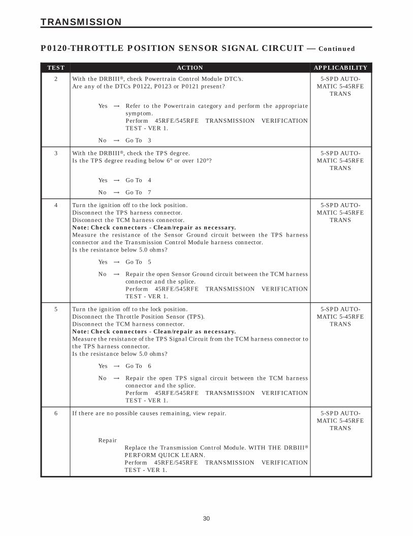
TEST ACTION APPLICABILITY
2 With the DRBIIIt, check Powertrain Control Module DTC’s.Are any of the DTCs P0122, P0123 or P0121 present?
5-SPD AUTO-MATIC 5-45RFE
TRANS
Yes → Refer to the Powertrain category and perform the appropriatesymptom.Perform 45RFE/545RFE TRANSMISSION VERIFICATIONTEST - VER 1.
No → Go To 3
3 With the DRBIIIt, check the TPS degree.Is the TPS degree reading below 6° or over 120°?
5-SPD AUTO-MATIC 5-45RFE
TRANS
Yes → Go To 4
No → Go To 7
4 Turn the ignition off to the lock position.Disconnect the TPS harness connector.Disconnect the TCM harness connector.Note: Check connectors - Clean/repair as necessary.Measure the resistance of the Sensor Ground circuit between the TPS harnessconnector and the Transmission Control Module harness connector.Is the resistance below 5.0 ohms?
5-SPD AUTO-MATIC 5-45RFE
TRANS
Yes → Go To 5
No → Repair the open Sensor Ground circuit between the TCM harnessconnector and the splice.Perform 45RFE/545RFE TRANSMISSION VERIFICATIONTEST - VER 1.
5 Turn the ignition off to the lock position.Disconnect the Throttle Position Sensor (TPS).Disconnect the TCM harness connector.Note: Check connectors - Clean/repair as necessary.Measure the resistance of the TPS Signal Circuit from the TCM harness connector tothe TPS harness connector.Is the resistance below 5.0 ohms?
5-SPD AUTO-MATIC 5-45RFE
TRANS
Yes → Go To 6
No → Repair the open TPS signal circuit between the TCM harnessconnector and the splice.Perform 45RFE/545RFE TRANSMISSION VERIFICATIONTEST - VER 1.
6 If there are no possible causes remaining, view repair. 5-SPD AUTO-MATIC 5-45RFE
TRANS
RepairReplace the Transmission Control Module. WITH THE DRBIIItPERFORM QUICK LEARN.Perform 45RFE/545RFE TRANSMISSION VERIFICATIONTEST - VER 1.
30
TRANSMISSION
P0120-THROTTLE POSITION SENSOR SIGNAL CIRCUIT — Continued

TEST ACTION APPLICABILITY
7 The conditions necessary to set this DTC are not present at this time. Using theschematics as a guide, inspect the wiring and connectors specific to this circuit.Wiggle the wires while checking for shorts and open circuits.Pay particular attention to the the point where the TPS signal and sensor groundcircuits splice off from the engine circuits.Were there any problems found?
5-SPD AUTO-MATIC 5-45RFE
TRANS
Yes → Repair wiring and/or connector as necessary.Perform 45RFE/545RFE TRANSMISSION VERIFICATIONTEST - VER 1.
No → Go To 8
8 Ignition On, Engine Not Running.With the DRBIIIt, read the TPS voltage.While monitoring the DRBIIIt, slowly open and close the throttle.Is the TPS voltage change smooth?
5-SPD AUTO-MATIC 5-45RFE
TRANS
Yes → Test Complete.
No → Replace the Throttle Position Sensor.Perform 45RFE/545RFE TRANSMISSION VERIFICATIONTEST - VER 1.
31
TRANSMISSION
P0120-THROTTLE POSITION SENSOR SIGNAL CIRCUIT — Continued

Symptom:P0218-HIGH TEMPERATURE OPERATION ACTIVATED
When Monitored and Set Condition:
P0218-HIGH TEMPERATURE OPERATION ACTIVATED
When Monitored: Whenever the engine is running.
Set Condition: Immediately when the Overheat shift schedule is activated 116 degrees Ctransmission oil temp. (240 degrees F. Trans oil temp).
POSSIBLE CAUSES
ENGINE COOLING SYSTEM
TRANSMISSION OIL PUMP FLOW
HIGH TEMPERATURE OPERATIONS ACTIVATED
TEST ACTION APPLICABILITY
1 NOTE: Low fluid level can be the cause of many transmission problems. Ifthe fluid level is low locate and repair the leak then check and adjust thefluid level per the service information.NOTE: Always perform diagnostics with a fully charged battery to avoidfalse symptoms.With the DRBIIIt, read the engine DTC’s. Check and repair all engine DTC’s priorto performing transmission symptom diagnostics.With the DRBIIIt, read Transmission DTC’s. Record all DTC’s and 1 Trip Failures.NOTE: Diagnose 1 Trip Failures as a fully matured DTC.Using the wiring diagram/schematic as a guide, inspect the wiring and connectors.Repair as necessary.Perform the Shift Lever Position Test. If the test does not pass, refer to Symptom testfor P0706 Check Shifter Signal.For Gear Ratio DTC’s, check and record all CVI’s.Most DTC’s set on start up but some must be set by driving the vehicle such that alldiagnostic monitors have run.Note: Verify flash level of transmission controller. Some problems arecorrected by software upgrades to the transmission controller.NOTE: Check for applicable TSB’s related to the problem.Perform this procedure prior to Symptom diagnosis.
All
ContinueGo To 2
2 Perform the Oil Pump Flow test per the Service Information.Did the Oil Pump Flow test pass?
5-SPD AUTO-MATIC 5-45RFE
TRANS
Yes → Go To 3
No → Repair the cause of either a low, or no Transmission Oil PumpFlow. Refer to the Service Information for the proper repairprocedure.Perform 45RFE/545RFE TRANSMISSION VERIFICATIONTEST - VER 1.
32
TRANSMISSION

TEST ACTION APPLICABILITY
3 Perform Engine Cooling System diagnostics per the Service Information.Is the Engine Cooling System functioning properly?
5-SPD AUTO-MATIC 5-45RFE
TRANS
Yes → Go To 4
No → Repair the cause of the engine overheating. Refer to the ServiceInformation for the proper repair procedure.Perform 45RFE/545RFE TRANSMISSION VERIFICATIONTEST - VER 1.
4 This DTC is an informational DTC designed to aid the Technician in diagnosing shiftquality complaints.This DTC indicates that the transmission has been operating in the 9Overheat9 shiftschedule which may generate a customer complaint.The customer driving patterns may indicate the need for an additional transmissionoil cooler.If there are no possible causes remaining, view repair.
5-SPD AUTO-MATIC 5-45RFE
TRANS
RepairRepair the cause of transmission overheating. Refer to the ServiceInformation for the proper repair procedure. Make sure to checkfor any TSBs pertaining to this problem.Perform 45RFE/545RFE TRANSMISSION VERIFICATIONTEST - VER 1.
33
TRANSMISSION
P0218-HIGH TEMPERATURE OPERATION ACTIVATED — Continued

Symptom:P0604-INTERNAL TCM
When Monitored and Set Condition:
P0604-INTERNAL TCM
When Monitored: Continuously with the key on.
Set Condition: When ever the TCM detects an internal controller problem.
POSSIBLE CAUSES
TCM INTERNAL ERROR
TEST ACTION APPLICABILITY
1 If there are no possible causes remaining, view repair. 5-SPD AUTO-MATIC 5-45RFE
TRANS
RepairThe Transmission Control Module is reporting internal errors andmust be replaced. WITH THE DRBIIIt PERFORM QUICKLEARN.Perform 45RFE/545RFE TRANSMISSION VERIFICATIONTEST - VER 1.
34
TRANSMISSION

Symptom:P0605-INTERNAL TCM
When Monitored and Set Condition:
P0605-INTERNAL TCM
When Monitored: Continuously with the key on
Set Condition: When ever the TCM detects an internal controller problem.
POSSIBLE CAUSES
TCM INTERNAL ERROR
TEST ACTION APPLICABILITY
1 If there are no possible causes remaining, view repair. 5-SPD AUTO-MATIC 5-45RFE
TRANS
RepairThe Transmission Control Module is reporting internal errors andmust be replaced. WITH THE DRBIIIt PERFORM QUICKLEARN.Perform 45RFE/545RFE TRANSMISSION VERIFICATIONTEST - VER 1.
35
TRANSMISSION

Symptom:P0613-INTERNAL TCM
When Monitored and Set Condition:
P0613-INTERNAL TCM
When Monitored: Continuously with the key on.
Set Condition: When ever the TCM detects an internal controller problem.
POSSIBLE CAUSES
GROUND CIRCUIT OPEN
TCM INTERNAL ERROR
TEST ACTION APPLICABILITY
1 Turn the ignition off to the lock position.Disconnect the TCM harness connector.Note: Check connectors - Clean/repair as necessary.Using a 12-volt test light connected to 12-volts, check all three ground circuits in theTCM harness connector.NOTE: The test light must illuminate brightly. Compare the brightness tothat of a direct connection to the battery.Does the test light illuminate brightly on all three ground circuits?
5-SPD AUTO-MATIC 5-45RFE
TRANS
Yes → Go To 2
No → Repair the Ground circuit(s) as necessary. Check main groundconnection to engine block and/or chassis.Perform 45RFE/545RFE TRANSMISSION VERIFICATIONTEST - VER 1.
2 If there are no possible causes remaining, view repair.View repair.
5-SPD AUTO-MATIC 5-45RFE
TRANS
RepairThe Transmission Control Module is reporting internal errors andmust be replaced. WITH THE DRBIIIt PERFORM QUICKLEARN.Perform 45RFE/545RFE TRANSMISSION VERIFICATIONTEST - VER 1.
36
TRANSMISSION

Symptom:P0706-CHECK SHIFTER SIGNAL
When Monitored and Set Condition:
P0706-CHECK SHIFTER SIGNAL
When Monitored: Continuously with the ignition key on.
Set Condition: 3 occurrences in one key start of an invalid PRNDL code which lasts formore than 0.1 second.
POSSIBLE CAUSES
INTERMITTENT WIRING & CONNECTORS
SHIFT LINKAGE OUT OF ADJUSTMENT.
TRS T1 SENSE CIRCUIT OPEN
TRS T2 SENSE CIRCUIT OPEN
TRS T3 SENSE CIRCUIT OPEN
TRS T41 SENSE CIRCUIT OPEN
TRS T42 SENSE CIRCUIT OPEN
TRS T1 SENSE CIRCUIT SHORT TO GROUND
TRS T2 SENSE CIRCUIT SHORT TO GROUND
TRS T3 SENSE CIRCUIT SHORT TO GROUND
TRS T41 SENSE CIRCUIT SHORT TO GROUND
TRS T42 SENSE CIRCUIT SHORT TO GROUND
TRS T1 SENSE CIRCUIT SHORT TO VOLTAGE
TRS T2 SENSE CIRCUIT SHORT TO VOLTAGE
TRS T3 SENSE CIRCUIT SHORT TO VOLTAGE
TRS T41 SENSE CIRCUIT SHORT TO VOLTAGE
TRS T42 SENSE CIRCUIT SHORT TO VOLTAGE
TRANSMISSION RANGE SENSOR
TCM - TRS T1 SENSE CIRCUIT
TCM - TRS T2 SENSE CIRCUIT
TCM - TRS T3 SENSE CIRCUIT
TCM - TRS T41 SENSE CIRCUIT
TCM - TRS T42 SENSE CIRCUIT
37
TRANSMISSION

TEST ACTION APPLICABILITY
1 NOTE: Low fluid level can be the cause of many transmission problems. Ifthe fluid level is low locate and repair the leak then check and adjust thefluid level per the service information.NOTE: Always perform diagnostics with a fully charged battery to avoidfalse symptoms.With the DRBIIIt, read the engine DTC’s. Check and repair all engine DTC’s priorto performing transmission symptom diagnostics.With the DRBIIIt, read Transmission DTC’s. Record all DTC’s and 1 Trip Failures.NOTE: Diagnose 1 Trip Failures as a fully matured DTC.Using the wiring diagram/schematic as a guide, inspect the wiring and connectors.Repair as necessary.Perform the Shift Lever Position Test. If the test does not pass, refer to Symptom testfor P0706 Check Shifter Signal.For Gear Ratio DTC’s, check and record all CVI’s.Most DTC’s set on start up but some must be set by driving the vehicle such that alldiagnostic monitors have run.Note: Verify flash level of transmission controller. Some problems arecorrected by software upgrades to the transmission controller.NOTE: Check for applicable TSB’s related to the problem.Perform this procedure prior to Symptom diagnosis.
All
ContinueGo To 2
2 With the DRBIIIt, perform the Shift Lever Position Test.Select the test outcome from the following:
5-SPD AUTO-MATIC 5-45RFE
TRANS
Test passes:Go To 3
Test fails with DTC:Go To 4
Test fails without DTC:Go To 27
3 The conditions necessary to set this DTC are not present at this time. Using theschematics as a guide, inspect the wiring and connectors specific to this circuit.Wiggle the wires while checking for shorts and open circuits.Were there any problems found?
5-SPD AUTO-MATIC 5-45RFE
TRANS
Yes → Repair as necessary.Perform 45RFE/545RFE TRANSMISSION VERIFICATIONTEST - VER 1.
No → Test Complete.
38
TRANSMISSION
P0706-CHECK SHIFTER SIGNAL — Continued

TEST ACTION APPLICABILITY
4 Turn the ignition off to the lock position.Remove the Starter Relay from the PDC.NOTE: Failure to remove the Starter Relay can cause a TCM - No Responsecondition.Install Transmission Simulator Miller tool #8333.Ignition on, engine not running.With the DRBIIIt, perform the Shift Lever Position Test.When the DRBIIIt instructs you to put the Gear Selector in a particular position, youmust do so using the selector switch on the Transmission Simulator.The LED for the gear position in question must be illuminated on the TransmissionSimulator prior to pressing 9ENTER9 on the DRBIIIt.NOTE: When the DRBIIIt requests the O/D off button be depressed, youmust use the O/D OFF button in the vehicle or you will fail the Shift LeverPosition Test with a DTC P0613 (11).Did the Shift Lever Position test pass?
5-SPD AUTO-MATIC 5-45RFE
TRANS
Yes → Go To 5
No → Go To 6
NOTE: Make sure to disconnect the Transmission Simulator and reconnectall disconnected connectors before proceeding.
5 If there are no possible causes remaining, view repair. 5-SPD AUTO-MATIC 5-45RFE
TRANS
RepairReplace the Transmission Solenoid/TRS Assembly per the ServiceInformation.Perform 45RFE/545RFE TRANSMISSION VERIFICATIONTEST - VER 1.
6 With the DRBIIIt, observe the TRS sense circuits on the Input/Output screen. (C1thru C5)Move the shift lever from P to L, pausing momentarily in each gear position. Watchfor one of the circuits to not change state.Pick the one that did not change state.
5-SPD AUTO-MATIC 5-45RFE
TRANS
TRS T1 sense (C4)Go To 7
TRS T2 sense (C5)Go To 11
TRS T3 sense (C3)Go To 15
TRS T41 sense (C1)Go To 19
TRS T42 sense (C2)Go To 23
39
TRANSMISSION
P0706-CHECK SHIFTER SIGNAL — Continued

TEST ACTION APPLICABILITY
7 Turn the ignition off to the lock position.Disconnect the Transmission Solenoid/TRS Assembly harness connector.Disconnect the TCM harness connector.Note: Check connectors - Clean/repair as necessary.Measure the resistance of the TRS T1 Sense circuit from the TCM harness connectorto the Solenoid/TRS Assembly harness connector.Is the resistance above 5.0 ohms?
5-SPD AUTO-MATIC 5-45RFE
TRANS
Yes → Repair the TRS T1 circuit for an open.Perform 45RFE/545RFE TRANSMISSION VERIFICATIONTEST - VER 1.
No → Go To 8
8 Turn the ignition off to the lock position.Disconnect the Transmission Solenoid/TRS Assembly harness connector.Disconnect the TCM harness connector.Note: Check connectors - Clean/repair as necessary.Measure the resistance between ground and the TRS T1 Sense circuit in the TCMharness connector..Is the resistance below 5.0 ohms?
5-SPD AUTO-MATIC 5-45RFE
TRANS
Yes → Repair the TRS T1 Sense circuit for a short to ground.Perform 45RFE/545RFE TRANSMISSION VERIFICATIONTEST - VER 1.
No → Go To 9
9 Turn the ignition off to the lock position.Disconnect the Transmission Solenoid/TRS Assembly harness connector.Disconnect the TCM harness connector.Note: Check connectors - Clean/repair as necessary.Ignition on, engine not running.Measure the voltage of the TRS T1 Sense circuit in the TCM harness connector.Is the voltage above 0.5 volt?
5-SPD AUTO-MATIC 5-45RFE
TRANS
Yes → Repair the TRS T1 Sense circuit for a short to voltage.Perform 45RFE/545RFE TRANSMISSION VERIFICATIONTEST - VER 1.
No → Go To 10
10 If there are no possible causes remaining, view repair. 5-SPD AUTO-MATIC 5-45RFE
TRANS
RepairReplace the Transmission Control Module. WITH THE DRBIIItPERFORM QUICK LEARN.Perform 45RFE/545RFE TRANSMISSION VERIFICATIONTEST - VER 1.
40
TRANSMISSION
P0706-CHECK SHIFTER SIGNAL — Continued

TEST ACTION APPLICABILITY
11 Turn the ignition off to the lock position.Disconnect the Transmission Solenoid/TRS Assembly harness connector.Disconnect the TCM harness connector.Note: Check connectors - Clean/repair as necessary.Measure the resistance of the TRS T2 Sense circuit from the TCM harness connectorto the Solenoid/TRS Assembly harness connector.Is the resistance above 5.0 ohms?
5-SPD AUTO-MATIC 5-45RFE
TRANS
Yes → Repair the TRS T2 Sense circuit for an open.Perform 45RFE/545RFE TRANSMISSION VERIFICATIONTEST - VER 1.
No → Go To 12
12 Turn the ignition off to the lock position.Disconnect the Transmission Solenoid/TRS Assembly harness connector.Disconnect the TCM harness connector.Note: Check connectors - Clean/repair as necessary.Measure the resistance between ground and the TRS T2 Sense circuit in the TCMharness connector.Is the resistance below 5.0 ohms?
5-SPD AUTO-MATIC 5-45RFE
TRANS
Yes → Repair the TRS T2 Sense circuit for a short to ground.Perform 45RFE/545RFE TRANSMISSION VERIFICATIONTEST - VER 1.
No → Go To 13
13 Turn the ignition off to the lock position.Disconnect the Transmission Solenoid/TRS Assembly harness connector.Disconnect the TCM harness connector.Note: Check connectors - Clean/repair as necessary.Ignition on, engine not running.Measure the voltage of the TRS T2 Sense circuit in the TCM harness connector.Is the voltage above 0.5 volt?
5-SPD AUTO-MATIC 5-45RFE
TRANS
Yes → Repair the TRS T2 Sense circuit for a short to voltage.Perform 45RFE/545RFE TRANSMISSION VERIFICATIONTEST - VER 1.
No → Go To 14
14 If there are no possible causes remaining, view repair. 5-SPD AUTO-MATIC 5-45RFE
TRANS
RepairReplace the Transmission Control Module. WITH THE DRBIIItPERFORM QUICK LEARN.Perform 45RFE/545RFE TRANSMISSION VERIFICATIONTEST - VER 1.
41
TRANSMISSION
P0706-CHECK SHIFTER SIGNAL — Continued

TEST ACTION APPLICABILITY
15 Turn the ignition off to the lock position.Disconnect the Transmission Solenoid/TRS Assembly harness connector.Disconnect the TCM harness connector.Note: Check connectors - Clean/repair as necessary.Measure the resistance of the TRS T3 Sense circuit from the TCM harness connectorto the Solenoid/TRS Assembly harness connector.Is the resistance above 5.0 ohms?
5-SPD AUTO-MATIC 5-45RFE
TRANS
Yes → Repair the open TRS T3 Sense circuit.Perform 45RFE/545RFE TRANSMISSION VERIFICATIONTEST - VER 1.
No → Go To 16
16 Turn the ignition off to the lock position.Disconnect the Transmission Solenoid/TRS Assembly harness connector.Disconnect the TCM harness connector.Note: Check connectors - Clean/repair as necessary.Measure the resistance between ground and the TRS T3 Sense circuit in the TCMharness connector.Is the resistance below 5.0 ohms?
5-SPD AUTO-MATIC 5-45RFE
TRANS
Yes → Repair the TRS T3 Sense circuit for a short to ground.Perform 45RFE/545RFE TRANSMISSION VERIFICATIONTEST - VER 1.
No → Go To 17
17 Turn the ignition off to the lock position.Disconnect the Transmission Solenoid/TRS Assembly harness connector.Disconnect the TCM harness connector.Note: Check connectors - Clean/repair as necessary.Ignition on, engine not running.Measure the voltage of the TRS T3 Sense circuit at the TCM harness connector.Is the voltage above 0.5 volt?
5-SPD AUTO-MATIC 5-45RFE
TRANS
Yes → Repair the TRS T3 Sense circuit for a short to voltage.Perform 45RFE/545RFE TRANSMISSION VERIFICATIONTEST - VER 1.
No → Go To 18
18 If there are no possible causes remaining, view repair. 5-SPD AUTO-MATIC 5-45RFE
TRANS
RepairReplace the Transmission Control Module. WITH THE DRBIIItPERFORM QUICK LEARN.Perform 45RFE/545RFE TRANSMISSION VERIFICATIONTEST - VER 1.
42
TRANSMISSION
P0706-CHECK SHIFTER SIGNAL — Continued

TEST ACTION APPLICABILITY
19 Turn the ignition off to the lock position.Disconnect the Transmission Solenoid/TRS Assembly harness connector.Disconnect the TCM harness connector.Note: Check connectors - Clean/repair as necessary.Measure the resistance of the TRS T41 Sense circuit from the TCM harnessconnector to the Solenoid/TRS Assembly harness connector.Is the resistance above 5.0 ohms?
5-SPD AUTO-MATIC 5-45RFE
TRANS
Yes → Repair open TRS T41 Sense circuit.Perform 45RFE/545RFE TRANSMISSION VERIFICATIONTEST - VER 1.
No → Go To 20
20 Turn the ignition off to the lock position.Disconnect the Transmission Solenoid/TRS Assembly harness connector.Disconnect the TCM harness connector.Note: Check connectors - Clean/repair as necessary.Measure the resistance between ground and the TRS T41 Sense circuit in the TCMharness connector.Is the resistance below 5.0 ohms?
5-SPD AUTO-MATIC 5-45RFE
TRANS
Yes → Repair the TRS T41 Sense circuit for a short to ground.Perform 45RFE/545RFE TRANSMISSION VERIFICATIONTEST - VER 1.
No → Go To 21
21 Turn the ignition off to the lock position.Disconnect the Transmission Solenoid/TRS Assembly harness connector.Disconnect the TCM harness connector.Note: Check connectors - Clean/repair as necessary.Ignition on, engine not running.Measure the voltage of the TRS T41 Sense circuit in the TCM harness connector.Is the voltage above 0.5 volt?
5-SPD AUTO-MATIC 5-45RFE
TRANS
Yes → Repair the TRS T41 Sense circuit for a short to voltage.Perform 45RFE/545RFE TRANSMISSION VERIFICATIONTEST - VER 1.
No → Go To 22
22 If there are no possible causes remaining, view repair. 5-SPD AUTO-MATIC 5-45RFE
TRANS
RepairReplace the Transmission Control Module. WITH THE DRBIIItPERFORM QUICK LEARN.Perform 45RFE/545RFE TRANSMISSION VERIFICATIONTEST - VER 1.
43
TRANSMISSION
P0706-CHECK SHIFTER SIGNAL — Continued

TEST ACTION APPLICABILITY
23 Turn the ignition off to the lock position.Disconnect the Transmission Solenoid/TRS Assembly harness connector.Disconnect the TCM harness connector.Note: Check connectors - Clean/repair as necessary.Measure the resistance of the TRS T42 Sense circuit from the TCM harnessconnector to the Solenoid/TRS Assembly harness connector.Is the resistance above 5.0 ohms?
5-SPD AUTO-MATIC 5-45RFE
TRANS
Yes → Repair the TRS T42 Sense circuit for an open.Perform 45RFE/545RFE TRANSMISSION VERIFICATIONTEST - VER 1.
No → Go To 24
24 Turn the ignition off to the lock position.Disconnect the Transmission Solenoid/TRS Assembly harness connector.Disconnect the TCM harness connector.Note: Check connectors - Clean/repair as necessary.Measure the resistance between ground and the TRS T42 Sense circuit in the TCMharness connector.Is the resistance below 5.0 ohms?
5-SPD AUTO-MATIC 5-45RFE
TRANS
Yes → Repair the TRS T42 Sense circuit for a short to ground.Perform 45RFE/545RFE TRANSMISSION VERIFICATIONTEST - VER 1.
No → Go To 25
25 Turn the ignition off to the lock position.Disconnect the Transmission Solenoid/TRS Assembly harness connector.Disconnect the TCM harness connector.Note: Check connectors - Clean/repair as necessary.Ignition on, engine not running.Measure the voltage of the TRS T42 Sense circuit at the TCM harness connector.Is the voltage above 0.5 volt?
5-SPD AUTO-MATIC 5-45RFE
TRANS
Yes → Repair the TRS T42 Sense circuit for a short to voltage.Perform 45RFE/545RFE TRANSMISSION VERIFICATIONTEST - VER 1.
No → Go To 26
26 If there are no possible causes remaining, view repair. 5-SPD AUTO-MATIC 5-45RFE
TRANS
RepairReplace the Transmission Control Module. WITH THE DRBIIItPERFORM QUICK LEARN.Perform 45RFE/545RFE TRANSMISSION VERIFICATIONTEST - VER 1.
27 If there are no possible causes remaining, view repair. 5-SPD AUTO-MATIC 5-45RFE
TRANS
RepairAdjust the shift linkage per the Service Information.Perform 45RFE/545RFE TRANSMISSION VERIFICATIONTEST - VER 1.
44
TRANSMISSION
P0706-CHECK SHIFTER SIGNAL — Continued

Symptom:P0715-INPUT SPEED SENSOR ERROR
When Monitored and Set Condition:
P0715-INPUT SPEED SENSOR ERROR
When Monitored: The transmission gear ratio is monitored continuously while thetransmission is in gear.
Set Condition: If there is an excessive change in input RPM in any gear. This DTC cantake up to five minutes of problem identification before illuminating the MIL.
POSSIBLE CAUSES
INTERMITTENT WIRING AND CONNECTORS
INPUT SPEED SENSOR SIGNAL CIRCUIT OPEN
SPEED SENSOR GROUND CIRCUIT OPEN
INPUT SPEED SENSOR SIGNAL CIRCUIT SHORT TO GROUND
SPEED SENSOR GROUND CIRCUIT SHORT TO GROUND
INPUT SPEED SENSOR SIGNAL CIRCUIT SHORT TO VOLTAGE
SPEED SENSOR GROUND CIRCUIT SHORT TO VOLTAGE
INPUT SPEED SENSOR
TCM - INPUT SPEED SENSOR
TEST ACTION APPLICABILITY
1 NOTE: Low fluid level can be the cause of many transmission problems. Ifthe fluid level is low locate and repair the leak then check and adjust thefluid level per the service information.NOTE: Always perform diagnostics with a fully charged battery to avoidfalse symptoms.With the DRBIIIt, read the engine DTC’s. Check and repair all engine DTC’s priorto performing transmission symptom diagnostics.With the DRBIIIt, read Transmission DTC’s. Record all DTC’s and 1 Trip Failures.NOTE: Diagnose 1 Trip Failures as a fully matured DTC.Using the wiring diagram/schematic as a guide, inspect the wiring and connectors.Repair as necessary.Perform the Shift Lever Position Test. If the test does not pass, refer to Symptom testfor P0706 Check Shifter Signal.For Gear Ratio DTC’s, check and record all CVI’s.Most DTC’s set on start up but some must be set by driving the vehicle such that alldiagnostic monitors have run.Note: Verify flash level of transmission controller. Some problems arecorrected by software upgrades to the transmission controller.NOTE: Check for applicable TSB’s related to the problem.Perform this procedure prior to Symptom diagnosis.
All
ContinueGo To 2
45
TRANSMISSION

TEST ACTION APPLICABILITY
2 Start the engine in park.With the DRBIIIt, observe the Input Speed Sensor Reading.Is the Input Speed Sensor Reading below 400 RPM?
5-SPD AUTO-MATIC 5-45RFE
TRANS
Yes → Go To 3
No → Go To 12
3 Turn the ignition off to the lock position.Remove the Starter Relay from the PDC.NOTE: Failure to remove the Starter Relay can cause a TCM - No Responsecondition.Install Transmission Simulator Miller tool #8333.Note: Check connectors - Clean/repair as necessary.Ignition on, engine not running.Using the Transmission Simulator, set the rotary knob to the middle (3000/1000)position. Turn the 9Input/Output9 switch to 9ON9.With the DRBIIIt, observe the Input and Output Speed Sensor readings.Does the input speed read 3000 RPM and the Output speed read 1000 RPM (within50 RPM)?
5-SPD AUTO-MATIC 5-45RFE
TRANS
Yes → Go To 4
No → Go To 5
4 If there are no possible causes remaining, view repair. 5-SPD AUTO-MATIC 5-45RFE
TRANS
RepairReplace the Input Speed Sensor.Perform 45RFE/545RFE TRANSMISSION VERIFICATIONTEST - VER 1.
5 Turn ignition switch to the lock positionDisconnect the TCM harness connector.Disconnect the Input Speed Sensor harness connector.Note: Check connectors - Clean/repair as necessary.Measure the resistance of the Input Speed Sensor Signal circuit from the TCMconnector to the Input Speed Sensor connector.Is the resistance above 5.0 ohms?
5-SPD AUTO-MATIC 5-45RFE
TRANS
Yes → Repair the Input Speed Sensor Signal circuit for an open.Perform 45RFE/545RFE TRANSMISSION VERIFICATIONTEST - VER 1.
No → Go To 6
6 Turn the ignition off to the lock position.Disconnect the TCM harness connector.Disconnect the Input Speed Sensor harness connector.Note: Check connectors - Clean/repair as necessary.Measure the resistance of the Speed Sensor Ground circuit from the TCM harnessconnector to the Input Speed Sensor harness connector.Is the resistance above 5.0 ohms?
5-SPD AUTO-MATIC 5-45RFE
TRANS
Yes → Repair the Speed Sensor Ground circuit for an open.Perform 45RFE/545RFE TRANSMISSION VERIFICATIONTEST - VER 1.
No → Go To 7
46
TRANSMISSION
P0715-INPUT SPEED SENSOR ERROR — Continued

TEST ACTION APPLICABILITY
7 Turn the ignition off to the lock position.Disconnect the TCM harness connector.Disconnect the Input Speed Sensor harness connector.Note: Check connectors - Clean/repair as necessary.Measure the resistance between ground and the Input Speed Sensor Signal circuit.Is the resistance Below 5.0 ohms?
5-SPD AUTO-MATIC 5-45RFE
TRANS
Yes → Repair the Input Speed Sensor Signal circuit for a short toground.Perform 45RFE/545RFE TRANSMISSION VERIFICATIONTEST - VER 1.
No → Go To 8
8 Turn the ignition off to the lock position.Disconnect the TCM harness connector.Disconnect the Input Speed Sensor harness connector.Note: Check connectors - Clean/repair as necessary.Measure the resistance between ground and the Speed Sensor Ground circuit.Is the resistance Below 5.0 ohms?
5-SPD AUTO-MATIC 5-45RFE
TRANS
Yes → Repair the Speed Sensor Ground circuit for a short to ground.Perform 45RFE/545RFE TRANSMISSION VERIFICATIONTEST - VER 1.
No → Go To 9
9 Turn the ignition off to the lock position.Disconnect the TCM harness connector.Remove the Transmission Control Relay from the PDC.Note: Check connectors - Clean/repair as necessary.Place a jumper wire between the Fused B+ circuit and the Transmission ControlRelay Output circuit in the Transmission Control Relay connector.Ignition on, engine not running.Measure the voltage of the Input Speed Sensor Signal circuit in the TCM harnessconnector.Is the voltage above 0.5 volts?
5-SPD AUTO-MATIC 5-45RFE
TRANS
Yes → Repair the Input Speed Sensor Signal circuit for a short tovoltage.Perform 45RFE/545RFE TRANSMISSION VERIFICATIONTEST - VER 1.
No → Go To 10
10 Turn the ignition off to the lock position.Disconnect the TCM harness connector.Remove the Transmission Control Relay from the PDC.Note: Check connectors - Clean/repair as necessary.Place a jumper wire between the fused B+ circuit and the Transmission ControlRelay Output circuit in the Transmission Control Relay connector.Ignition on, engine not running.Measure the voltage of the Speed Sensor Ground circuit in the TCM harnessconnector.Is the voltage above 0.5 volts?
5-SPD AUTO-MATIC 5-45RFE
TRANS
Yes → Repair the Speed Sensor Ground circuit for a short to voltage.Perform 45RFE/545RFE TRANSMISSION VERIFICATIONTEST - VER 1.
No → Go To 11
47
TRANSMISSION
P0715-INPUT SPEED SENSOR ERROR — Continued

TEST ACTION APPLICABILITY
11 If there are no possible causes remaining, view repair. 5-SPD AUTO-MATIC 5-45RFE
TRANS
RepairReplace the Transmission Control Module. WITH THE DRBIIItPERFORM QUICK LEARN.Perform 45RFE/545RFE TRANSMISSION VERIFICATIONTEST - VER 1.
12 The conditions necessary to set this DTC are not present at this time. Using theschematics as a guide, inspect the wiring and connectors specific to this circuit.Wiggle the wires while checking for shorts and open circuits.Were any problems found?
5-SPD AUTO-MATIC 5-45RFE
TRANS
Yes → Repair as necessary.Perform 45RFE/545RFE TRANSMISSION VERIFICATIONTEST - VER 1.
No → Test Complete.
48
TRANSMISSION
P0715-INPUT SPEED SENSOR ERROR — Continued

Symptom:P0720-OUTPUT SPEED SENSOR ERROR
When Monitored and Set Condition:
P0720-OUTPUT SPEED SENSOR ERROR
When Monitored: The transmission gear ratio is monitored continuously while thetransmission is in gear.
Set Condition: If there is an excessive change in output RPM in any gear. This DTC cantake up to five minutes of problem identification before illuminating the MIL.
POSSIBLE CAUSES
INTERMITTENT WIRING AND CONNECTORS
OUTPUT SPEED SENSOR SIGNAL CIRCUIT OPEN
SPEED SENSOR GROUND CIRCUIT OPEN
OUTPUT SPEED SENSOR SIGNAL CIRCUIT SHORT TO GROUND
SPEED SENSOR GROUND CIRCUIT SHORT TO GROUND
OUTPUT SPEED SENSOR SIGNAL CIRCUIT SHORT TO VOLTAGE
SPEED SENSOR GROUND CIRCUIT SHORT TO VOLTAGE
OUTPUT SPEED SENSOR
TCM - OUTPUT SPEED SENSOR
TEST ACTION APPLICABILITY
1 NOTE: Low fluid level can be the cause of many transmission problems. Ifthe fluid level is low locate and repair the leak then check and adjust thefluid level per the service information.NOTE: Always perform diagnostics with a fully charged battery to avoidfalse symptoms.With the DRBIIIt, read the engine DTC’s. Check and repair all engine DTC’s priorto performing transmission symptom diagnostics.With the DRBIIIt, read Transmission DTC’s. Record all DTC’s and 1 Trip Failures.NOTE: Diagnose 1 Trip Failures as a fully matured DTC.Using the wiring diagram/schematic as a guide, inspect the wiring and connectors.Repair as necessary.Perform the Shift Lever Position Test. If the test does not pass, refer to Symptom testfor P0706 Check Shifter Signal.For Gear Ratio DTC’s, check and record all CVI’s.Most DTC’s set on start up but some must be set by driving the vehicle such that alldiagnostic monitors have run.Note: Verify flash level of transmission controller. Some problems arecorrected by software upgrades to the transmission controller.NOTE: Check for applicable TSB’s related to the problem.Perform this procedure prior to Symptom diagnosis.
All
ContinueGo To 2
49
TRANSMISSION

TEST ACTION APPLICABILITY
2 Turn the ignition off to the lock position.CAUTION: Properly support the vehicle and raise all drive wheels off theground.Start the engine in park.Place the transmission gear selector in drive, release foot from brake.WARNING: BE SURE TO KEEP HANDS AND FEET CLEAR OF ROTATINGWHEELS.With the DRBIIIt, monitor the Output Speed Sensor RPM.Is the Output Speed Sensor RPM below 100 RPM?
5-SPD AUTO-MATIC 5-45RFE
TRANS
Yes → Go To 3
No → Go To 12
3 Turn the ignition off to the lock position.Remove the Starter Relay.NOTE: Failure to remove the Starter Relay can cause a TCM - No Responsecondition.Install the Transmission Simulator, Miller tool #8333.Note: Check connectors - Clean/repair as necessary.Ignition on, engine not running.With the Transmission Simulator, set the 9Input/Output Speed9 switch to 9ON9 andthe rotary switch to the 93000/10009 position.With the DRBIIIt, read the Input and Output Speed Sensor readings.Does the Input Speed read 3000 RPM and the Output Speed read 1000 RPM, ± 50RPM?
5-SPD AUTO-MATIC 5-45RFE
TRANS
Yes → Go To 4
No → Go To 5
4 If there are no possible causes remaining, view repair. 5-SPD AUTO-MATIC 5-45RFE
TRANS
RepairReplace the Output Speed Sensor.Perform 45RFE/545RFE TRANSMISSION VERIFICATIONTEST - VER 1.
5 Turn the ignition off to the lock position.Disconnect the TCM harness connector.Disconnect the Output Speed Sensor harness connector.Note: Check connectors - Clean/repair as necessary.Measure the resistance of the Output Speed Sensor Signal circuit from the TCMharness connector to the Output Speed Sensor harness connector.Is the resistance above 5.0 ohms?
5-SPD AUTO-MATIC 5-45RFE
TRANS
Yes → Repair the Output Speed Sensor Signal circuit for an open.Perform 45RFE/545RFE TRANSMISSION VERIFICATIONTEST - VER 1.
No → Go To 6
50
TRANSMISSION
P0720-OUTPUT SPEED SENSOR ERROR — Continued

TEST ACTION APPLICABILITY
6 Turn ignition switch to the lock positionDisconnect the TCM harness connector.Disconnect the Output Speed Sensor harness connector.Note: Check connectors - Clean/repair as necessary.Measure the resistance of the Speed Sensor Ground circuit from the TCM connectorto the Output Speed Sensor connector.Is the resistance above 5.0 ohms?
5-SPD AUTO-MATIC 5-45RFE
TRANS
Yes → Repair the Speed Sensor Ground circuit for an open.Perform 45RFE/545RFE TRANSMISSION VERIFICATIONTEST - VER 1.
No → Go To 7
7 Turn the ignition off to the lock position.Disconnect the TCM harness connector.Disconnect the Output Speed Sensor harness connector.Note: Check connectors - Clean/repair as necessary.Measure the resistance between ground and the Output Speed Sensor Signal circuit.Is the resistance Below 5.0 ohms?
5-SPD AUTO-MATIC 5-45RFE
TRANS
Yes → Repair the Output Speed Sensor Signal circuit for a short toground.Perform 45RFE/545RFE TRANSMISSION VERIFICATIONTEST - VER 1.
No → Go To 8
8 Turn the ignition off to the lock position.Disconnect the TCM harness connector.Disconnect the Output Speed Sensor harness connector.Note: Check connectors - Clean/repair as necessary.Measure the resistance between ground and the Speed Sensor Ground circuit.Is the resistance below 5.0 ohms?
5-SPD AUTO-MATIC 5-45RFE
TRANS
Yes → Repair the Speed Sensor Ground circuit for a short to ground.Perform 45RFE/545RFE TRANSMISSION VERIFICATIONTEST - VER 1.
No → Go To 9
9 Turn the ignition off to the lock position.Disconnect the TCM harness connector.Remove the Transmission Control Relay from the PDC.Note: Check connectors - Clean/repair as necessary.Place a jumper wire between the Fused B+ circuit and the Transmission RelayOutput circuit in the Transmission Control Relay connector.Turn ignition on.Measure the voltage of the Output Speed Sensor Signal circuit in the TCM harnessconnector.Is the voltage above 0.5 volts?
5-SPD AUTO-MATIC 5-45RFE
TRANS
Yes → Repair the Output Speed Sensor Signal circuit for a short tovoltage.Perform 45RFE/545RFE TRANSMISSION VERIFICATIONTEST - VER 1.
No → Go To 10
51
TRANSMISSION
P0720-OUTPUT SPEED SENSOR ERROR — Continued

TEST ACTION APPLICABILITY
10 Turn the ignition off to the lock position.Disconnect the TCM harness connector.Remove the Transmission Control Relay from the PDC.Note: Check connectors - Clean/repair as necessary.Place a jumper wire between the Fused B+ circuit and Transmission Control RelayOutput circuit in the Transmission Control Relay connector.Ignition on, engine not running.Measure the voltage of the Speed Sensor Ground circuit in the TCM harnessconnector.Is the voltage above 0.5 volts?
5-SPD AUTO-MATIC 5-45RFE
TRANS
Yes → Repair the Speed Sensor Ground circuit for a short to voltage.Perform 45RFE/545RFE TRANSMISSION VERIFICATIONTEST - VER 1.
No → Go To 11
11 If there are no possible causes remaining, view repair. 5-SPD AUTO-MATIC 5-45RFE
TRANS
RepairReplace the Transmission Control Module per the Service Infor-mation. WITH THE DRBIIIt PERFORM QUICK LEARN.Perform 45RFE/545RFE TRANSMISSION VERIFICATIONTEST - VER 1.
12 The conditions necessary to set this DTC are not present at this time. Using theschematics as a guide, inspect the wiring and connectors specific to this circuit.Wiggle the wires while checking for shorts and open circuits.Were there any problems found?
5-SPD AUTO-MATIC 5-45RFE
TRANS
Yes → Repair as necessary.Perform 45RFE/545RFE TRANSMISSION VERIFICATIONTEST - VER 1.
No → Test Complete.
52
TRANSMISSION
P0720-OUTPUT SPEED SENSOR ERROR — Continued

Symptom:P0725-ENGINE SPEED SENSOR CIRCUIT
When Monitored and Set Condition:
P0725-ENGINE SPEED SENSOR CIRCUIT
When Monitored: Continuously with engine running.
Set Condition: This code is set when the engine speed sensed by the TransmissionControl Module (TCM) is less than 400 RPM and the engine is running (As reported by thePCM over the communication bus) for 2 seconds. This DTC can take up to five minutes ofproblem identification before illuminating the MIL.
POSSIBLE CAUSES
RELATED PCM DTC’S PRESENT
INTERMITTENT WIRING AND CONNECTORS
CKP SIGNAL CIRCUIT OPEN TO TCM
SENSOR GROUND CIRCUIT OPEN TO TCM
TCM- ENGINE SPEED SENSOR CIRCUIT
TEST ACTION APPLICABILITY
1 NOTE: Low fluid level can be the cause of many transmission problems. Ifthe fluid level is low locate and repair the leak then check and adjust thefluid level per the service information.NOTE: Always perform diagnostics with a fully charged battery to avoidfalse symptoms.With the DRBIIIt, read the engine DTC’s. Check and repair all engine DTC’s priorto performing transmission symptom diagnostics.With the DRBIIIt, read Transmission DTC’s. Record all DTC’s and 1 Trip Failures.NOTE: Diagnose 1 Trip Failures as a fully matured DTC.Using the wiring diagram/schematic as a guide, inspect the wiring and connectors.Repair as necessary.Perform the Shift Lever Position Test. If the test does not pass, refer to Symptom testfor P0706 Check Shifter Signal.For Gear Ratio DTC’s, check and record all CVI’s.Most DTC’s set on start up but some must be set by driving the vehicle such that alldiagnostic monitors have run.Note: Verify flash level of transmission controller. Some problems arecorrected by software upgrades to the transmission controller.NOTE: Check for applicable TSB’s related to the problem.Perform this procedure prior to Symptom diagnosis.
All
ContinueGo To 2
53
TRANSMISSION

TEST ACTION APPLICABILITY
2 Ignition on, engine not running.With the DRBIIIt, check Powertrain Control Module DTC’s.Are the DTCs P0320, P1391, and/or P1398 present?
5-SPD AUTO-MATIC 5-45RFE
TRANS
Yes → Refer to the Powertrain category and perform the appropriatesymptom.Perform 45RFE/545RFE TRANSMISSION VERIFICATIONTEST - VER 1.
No → Go To 3
3 Start the engine.Allow the engine to idle.With the DRBIIIt, under 9Engine9, in Sensors, read and record 9Engine RPM9.With the DRBIIIt, under 9Transmission9, in 9Sensors9, read and record 9EngineRPM9.Compare the two readings.Are the two readings within 50 RPM of each other?
5-SPD AUTO-MATIC 5-45RFE
TRANS
No → Go To 4
Yes → Go To 7
4 Turn the ignition off to the lock position.Disconnect the CKP harness connector.Disconnect the TCM harness connector.Note: Check connectors - Clean/repair as necessary.Measure the resistance of the CKP Sensor Signal circuit between the CKP harnessconnector and the TCM harness connector.Is the resistance below 5.0 ohms?
5-SPD AUTO-MATIC 5-45RFE
TRANS
Yes → Go To 5
No → Repair the CKP Signal circuit for an open. Pay special attention tothe location of CKP Signal circuit spice to the TransmissionControl Module.Perform 45RFE/545RFE TRANSMISSION VERIFICATIONTEST - VER 1.
5 Turn the ignition off to the lock position.Disconnect the CKP Sensor harness connector.Disconnect the TCM harness connector.Note: Check connectors - Clean/repair as necessary.Measure the resistance of the Sensor Ground circuit between the CKP Sensor and theTCM harness connector.Is the resistance below 5.0 ohms?
5-SPD AUTO-MATIC 5-45RFE
TRANS
Yes → Go To 6
No → Repair the Sensor Ground circuit for an open. Pay special atten-tion to the location of Sensor Ground splice to the TCM.Perform 45RFE/545RFE TRANSMISSION VERIFICATIONTEST - VER 1.
54
TRANSMISSION
P0725-ENGINE SPEED SENSOR CIRCUIT — Continued

TEST ACTION APPLICABILITY
6 If there are no possible causes remaining, view repair. 5-SPD AUTO-MATIC 5-45RFE
TRANS
RepairReplace the Transmission Control Module. WITH THE DRBIIItPERFORM QUICK LEARN.Perform 45RFE/545RFE TRANSMISSION VERIFICATIONTEST - VER 1.
7 The conditions necessary to set this DTC are not present at this time. Using theschematics as a guide, inspect the wiring and connectors specific to this circuit.Wiggle the wires while checking for shorts and open circuits.Pay particular attention to the point where the CKP Signal circuit and the SensorGround circuit splice off from the engine circuits.Were there any problems found?
5-SPD AUTO-MATIC 5-45RFE
TRANS
Yes → Repair as necessary.Perform 45RFE/545RFE TRANSMISSION VERIFICATIONTEST - VER 1.
No → Test Complete.
55
TRANSMISSION
P0725-ENGINE SPEED SENSOR CIRCUIT — Continued

Symptom:P0731-GEAR RATIO ERROR IN 1ST
When Monitored and Set Condition:
P0731-GEAR RATIO ERROR IN 1ST
When Monitored: The transmission gear ratio is monitored continuously while thetransmission is in gear.
Set Condition: If the ratio of the Input RPM to the Output RPM does not match thecurrent gear ratio. This DTC can take up to five minutes of problem identification beforeilluminating the MIL.
POSSIBLE CAUSES
RELATED DTC’S PRESENT
INTERMITTENT GEAR RATIO ERRORS
INTERNAL TRANSMISSION
TEST ACTION APPLICABILITY
1 NOTE: Low fluid level can be the cause of many transmission problems. Ifthe fluid level is low locate and repair the leak then check and adjust thefluid level per the service information.NOTE: Always perform diagnostics with a fully charged battery to avoidfalse symptoms.With the DRBIIIt, read the engine DTC’s. Check and repair all engine DTC’s priorto performing transmission symptom diagnostics.With the DRBIIIt, read Transmission DTC’s. Record all DTC’s and 1 Trip Failures.NOTE: Diagnose 1 Trip Failures as a fully matured DTC.Using the wiring diagram/schematic as a guide, inspect the wiring and connectors.Repair as necessary.Perform the Shift Lever Position Test. If the test does not pass, refer to Symptom testfor P0706 Check Shifter Signal.For Gear Ratio DTC’s, check and record all CVI’s.Most DTC’s set on start up but some must be set by driving the vehicle such that alldiagnostic monitors have run.Note: Verify flash level of transmission controller. Some problems arecorrected by software upgrades to the transmission controller.NOTE: Check for applicable TSB’s related to the problem.Perform this procedure prior to Symptom diagnosis.
All
ContinueGo To 2
56
TRANSMISSION

TEST ACTION APPLICABILITY
2 With the DRBIIIt, check for other transmission DTC’sIf any of these DTC’s are present, perform their respective tests first.Are DTC’s P0944, P0715, P0720, P1794, P0867, P0932, P0868, or P0869 presentalso?
5-SPD AUTO-MATIC 5-45RFE
TRANS
Yes → Refer to Symptom list for the related symptom(s). If any of theseDTCs are present, they will cause a Speed Ratio Error. Performthe test for P0944 first if it is present.Perform 45RFE/545RFE TRANSMISSION VERIFICATIONTEST - VER 1.
No → Go To 3
3 With the DRBIIIt, perform the 1st Gear Clutch Test. Follow the instructions on theDRBIIIt.Increase the throttle angle or TPS Degree to 30°, for no more than a few seconds.CAUTION: Do not overheat the transmission.Did the Clutch Test pass, Input Speed remain at zero?
5-SPD AUTO-MATIC 5-45RFE
TRANS
Yes → Go To 4
No → Go To 5
4 The conditions to set this DTC are not currently present.Check the gearshift linkage adjustment.Intermittent Gear Ratio DTCs can be set by problems in the Input and Output SpeedSensor circuits and/or Speed Sensor Ground circuit.Check the speed sensor wiring and connectors for good connection, then perform awiggle test using the Transmission Simulator, Miller tool # 8333.Remove the Starter Relay from the PDC before using the Transmission SimulatorMiller tool # 8333.NOTE: Failure to remove the Starter Relay can cause a TCM - No Responsecondition.Gear ratio DTC’s can also be set under extreme temperature conditions, this isusually caused by an internal problem.Verify if the problem is only experienced under extreme hot or cold conditions.Were there any problems found.
5-SPD AUTO-MATIC 5-45RFE
TRANS
Yes → Repair as necessary.Perform 45RFE/545RFE TRANSMISSION VERIFICATIONTEST - VER 1.
No → Test Complete.
5 Repair or replace the transmission as necessary.If the transmission is to be repaired, and there were any line pressure DTC’s presentalong with this DTC, make sure to inspect the Transmission Oil Pump and PressureControl Solenoid per the Service Information procedures.If DTC’s P0876 and/or P0875 were present in addition to the P0731, replace theTransmission Solenoid/TRS Assembly in addition to necessary internal repairs.If there are no possible causes remaining, view repair.
5-SPD AUTO-MATIC 5-45RFE
TRANS
RepairRepair internal transmission problem or replace the transmissionper the Service Information.Perform 45RFE/545RFE TRANSMISSION VERIFICATIONTEST - VER 1.
57
TRANSMISSION
P0731-GEAR RATIO ERROR IN 1ST — Continued

Symptom:P0732-GEAR RATIO ERROR IN 2ND
When Monitored and Set Condition:
P0732-GEAR RATIO ERROR IN 2ND
When Monitored: The transmission gear ratio is monitored continuously while thetransmission is in gear.
Set Condition: If the ratio of the Input RPM to the Output RPM does not match thecurrent gear ratio. This DTC can take up to five minutes of problem identification beforeilluminating the MIL.
POSSIBLE CAUSES
RELATED DTC’S PRESENT
RELATED PRESSURE SWITCH DTC’S PRESENT
INTERMITTENT GEAR RATIO ERRORS
INTERNAL TRANSMISSION
TEST ACTION APPLICABILITY
1 NOTE: Low fluid level can be the cause of many transmission problems. Ifthe fluid level is low locate and repair the leak then check and adjust thefluid level per the service information.NOTE: Always perform diagnostics with a fully charged battery to avoidfalse symptoms.With the DRBIIIt, read the engine DTC’s. Check and repair all engine DTC’s priorto performing transmission symptom diagnostics.With the DRBIIIt, read Transmission DTC’s. Record all DTC’s and 1 Trip Failures.NOTE: Diagnose 1 Trip Failures as a fully matured DTC.Using the wiring diagram/schematic as a guide, inspect the wiring and connectors.Repair as necessary.Perform the Shift Lever Position Test. If the test does not pass, refer to Symptom testfor P0706 Check Shifter Signal.For Gear Ratio DTC’s, check and record all CVI’s.Most DTC’s set on start up but some must be set by driving the vehicle such that alldiagnostic monitors have run.Note: Verify flash level of transmission controller. Some problems arecorrected by software upgrades to the transmission controller.NOTE: Check for applicable TSB’s related to the problem.Perform this procedure prior to Symptom diagnosis.
All
ContinueGo To 2
58
TRANSMISSION

TEST ACTION APPLICABILITY
2 With the DRBIIIt, check for other transmission DTC’sIf any of these DTC’s are present, perform their respective tests first.Are DTC’s P0944, P0715, P0720, P1794, P0867, P0932, P0868 or P0869 present also?
5-SPD AUTO-MATIC 5-45RFE
TRANS
Yes → Refer to the Transmission category and perform the appropriatesymptom. If any of these DTCs are present, they will cause aSpeed Ratio Error. Perform the test for P0944 first if it is present.Perform 45RFE/545RFE TRANSMISSION VERIFICATIONTEST - VER 1.
No → Go To 3
3 With the DRBIIIt, perform the 2nd Gear Clutch Test. Follow the instructions on theDRBIIIt.Increase the throttle angle, TPS Degree to 30° for no more than a few seconds.CAUTION: Do not overheat the transmission.Did the clutch test pass, Input speed remain at zero?
5-SPD AUTO-MATIC 5-45RFE
TRANS
Yes → Go To 4
No → Go To 5
4 The conditions to set this DTC are not currently present.Check the gearshift linkage adjustment.Intermittent gear ratio DTCs can be set by problems in the Input and Output SpeedSensor circuits and/or Speed Sensor Ground circuit.Remove the starter relay before installing the Transmission Simulator.NOTE: Failure to remove the Starter Relay can cause a TCM - No Responsecondition.Check the speed sensor wiring and connectors for good connection, then perform awiggle test using the Transmission Simulator, Miller tool # 8333.Gear ratio DTC’s can also be set under extreme temperature conditions, this isusually caused by an internal problem.Verify if the problem is only experienced under extreme hot or cold conditions.Were there any problems found?
5-SPD AUTO-MATIC 5-45RFE
TRANS
Yes → Using the wiring diagram/schematic as a guide, inspect thewiring and connectors.Perform 45RFE/545RFE TRANSMISSION VERIFICATIONTEST - VER 1.
No → Test Complete.
5 With the DRBIIIt, check for other transmission DTC’sIs a DTC P0845 2C Hydraulic Pressure Switch and/or P0846 2C Pressure Switchpresent also?
5-SPD AUTO-MATIC 5-45RFE
TRANS
Yes → Repair or replace the Transmission or Solenoid/TRS assembly perthe Service Information.Perform 45RFE/545RFE TRANSMISSION VERIFICATIONTEST - VER 1.
No → Go To 6
59
TRANSMISSION
P0732-GEAR RATIO ERROR IN 2ND — Continued

TEST ACTION APPLICABILITY
6 Repair or replace the transmission as necessary.If the transmission is to be repaired, and there were any line pressure DTC’s presentalong with this DTC, make sure to inspect the Transmission Oil Pump and PressureControl Solenoid per the Service Information.If DTC’s P0846 and/or P0845 are also present, replace the Transmission Solenoid/TRS Assembly in addition to internal repairs.If there are no possible causes remaining, view repair.
5-SPD AUTO-MATIC 5-45RFE
TRANS
RepairRepair internal transmission problem or replace the transmissionper the Service Information.Perform 45RFE/545RFE TRANSMISSION VERIFICATIONTEST - VER 1.
60
TRANSMISSION
P0732-GEAR RATIO ERROR IN 2ND — Continued

Symptom:P0733-GEAR RATIO ERROR IN 3RD
When Monitored and Set Condition:
P0733-GEAR RATIO ERROR IN 3RD
When Monitored: The transmission gear ratio is monitored continuously while thetransmission is in gear.
Set Condition: If the ratio of the Input RPM to the Output RPM does not match thecurrent gear ratio. This DTC can take up to five minutes of problem identification beforeilluminating the MIL.
POSSIBLE CAUSES
RELATED DTC’S PRESENT
RELATED PRESSURE SWITCH DTC’S PRESENT
INTERMITTENT GEAR RATIO ERRORS
INTERNAL TRANSMISSION
TEST ACTION APPLICABILITY
1 NOTE: Low fluid level can be the cause of many transmission problems. Ifthe fluid level is low locate and repair the leak then check and adjust thefluid level per the service information.NOTE: Always perform diagnostics with a fully charged battery to avoidfalse symptoms.With the DRBIIIt, read the engine DTC’s. Check and repair all engine DTC’s priorto performing transmission symptom diagnostics.With the DRBIIIt, read Transmission DTC’s. Record all DTC’s and 1 Trip Failures.NOTE: Diagnose 1 Trip Failures as a fully matured DTC.Using the wiring diagram/schematic as a guide, inspect the wiring and connectors.Repair as necessary.Perform the Shift Lever Position Test. If the test does not pass, refer to Symptom testfor P0706 Check Shifter Signal.For Gear Ratio DTC’s, check and record all CVI’s.Most DTC’s set on start up but some must be set by driving the vehicle such that alldiagnostic monitors have run.Note: Verify flash level of transmission controller. Some problems arecorrected by software upgrades to the transmission controller.NOTE: Check for applicable TSB’s related to the problem.Perform this procedure prior to Symptom diagnosis.
All
ContinueGo To 2
61
TRANSMISSION

TEST ACTION APPLICABILITY
2 With the DRBIIIt, check for other transmission DTC’sIf any of these DTC’s are present, perform their respective tests first.Are the DTC’s P0944, P0715, P0720, P1794, P0867, P0932, P0868, or P0869 presentalso?
5-SPD AUTO-MATIC 5-45RFE
TRANS
Yes → Refer to the Transmission category and perform the appropriatesymptom.. If any of these DTCs are present, they will cause aSpeed Ratio Error. Perform the test for P0944 first if it is present.Perform 45RFE/545RFE TRANSMISSION VERIFICATIONTEST - VER 1.
No → Go To 3
3 With the DRBIIIt, check for other transmission DTC’sAre the DTCs P0870 OD Hydraulic Pressure Switch and/or P0871 OD PressureSwitch present also?
5-SPD AUTO-MATIC 5-45RFE
TRANS
Yes → Replace the Transmission Solenoid/TRS Assembly per the ServiceInformation.Perform 45RFE/545RFE TRANSMISSION VERIFICATIONTEST - VER 1.
No → Go To 4
4 With the DRBIIIt, perform the 3rd Gear Clutch Test. Follow the instructions on theDRBIIIt.Increase the throttle angle, TPS Degree, to 30° for no more than a few seconds.CAUTION: Do not overheat the transmission.Did the clutch test pass, Input speed remains at zero?
5-SPD AUTO-MATIC 5-45RFE
TRANS
Yes → Go To 5
No → Go To 6
5 The conditions to set this DTC are not currently present.Check the gearshift linkage adjustment.Intermittent gear ratio DTCs can be set by problems in the Input and Output SpeedSensor circuits and/or Speed Sensor Ground circuit.Remove the starter relay before installing the Transmission Simulator.NOTE: Failure to remove the Starter Relay can cause a TCM - No Responsecondition.Check the speed sensor wiring and connectors for good connection, then perform awiggle test using the Transmission Simulator (Miller tool # 8333).Gear ratio DTC’s can also be set under extreme temperature conditions, this isusually caused by an internal problem.Verify if the problem is only experienced under extreme hot or cold conditions.Were there any problems found.
5-SPD AUTO-MATIC 5-45RFE
TRANS
Yes → Repair as necessary.Perform 45RFE/545RFE TRANSMISSION VERIFICATIONTEST - VER 1.
No → Test Complete.
62
TRANSMISSION
P0733-GEAR RATIO ERROR IN 3RD — Continued

TEST ACTION APPLICABILITY
6 Repair or replace the transmission as necessary.If the transmission is to be repaired, and there were any line pressure DTC’s presentalong with this DTC, make sure to inspect the Transmission Oil Pump and PressureControl Solenoid per the Service Information.NOTE: If DTC’s P0871 and/or P0870 are also present, replace the TransmissionSolenoid/TRS Assembly in addition to necessary internal repairs.If there are no possible causes remaining, view repair.
5-SPD AUTO-MATIC 5-45RFE
TRANS
RepairRepair internal transmission problem or replace the transmissionper the Service Information.Perform 45RFE/545RFE TRANSMISSION VERIFICATIONTEST - VER 1.
63
TRANSMISSION
P0733-GEAR RATIO ERROR IN 3RD — Continued

Symptom:P0734-GEAR RATIO ERROR IN 4TH
When Monitored and Set Condition:
P0734-GEAR RATIO ERROR IN 4TH
When Monitored: The transmission gear ratio is monitored continuously while thetransmission is in gear.
Set Condition: If the ratio of the Input RPM to the Output RPM does not match thecurrent gear ratio. This DTC can take up to five minutes of problem identification beforeilluminating the MIL.
POSSIBLE CAUSES
RELATED DTC’S PRESENT
RELATED PRESSURE SWITCH DTC’S PRESENT
INTERNAL TRANSMISSION
TEST ACTION APPLICABILITY
1 NOTE: Low fluid level can be the cause of many transmission problems. Ifthe fluid level is low locate and repair the leak then check and adjust thefluid level per the service information.NOTE: Always perform diagnostics with a fully charged battery to avoidfalse symptoms.With the DRBIIIt, read the engine DTC’s. Check and repair all engine DTC’s priorto performing transmission symptom diagnostics.With the DRBIIIt, read Transmission DTC’s. Record all DTC’s and 1 Trip Failures.NOTE: Diagnose 1 Trip Failures as a fully matured DTC.Using the wiring diagram/schematic as a guide, inspect the wiring and connectors.Repair as necessary.Perform the Shift Lever Position Test. If the test does not pass, refer to Symptom testfor P0706 Check Shifter Signal.For Gear Ratio DTC’s, check and record all CVI’s.Most DTC’s set on start up but some must be set by driving the vehicle such that alldiagnostic monitors have run.Note: Verify flash level of transmission controller. Some problems arecorrected by software upgrades to the transmission controller.NOTE: Check for applicable TSB’s related to the problem.Perform this procedure prior to Symptom diagnosis.
All
ContinueGo To 2
64
TRANSMISSION

TEST ACTION APPLICABILITY
2 With the DRBIIIt, check for other transmission DTC’sIf any of these DTC’s are present, perform their respective tests first.Are the DTC’s P0944, P0715, P0720, P1794, P0867, P0932, P0868 or P0869 presentalso?
5-SPD AUTO-MATIC 5-45RFE
TRANS
Yes → Refer to the Transmission category and perform the appropriatesymptom. If any of these DTCs are present, they will cause aSpeed Ratio Error. Perform the test for P0944 first if it is present.Perform 45RFE/545RFE TRANSMISSION VERIFICATIONTEST - VER 1.
No → Go To 3
3 With the DRBIIIt, check for other transmission DTC’sAre the DTCs P0987 4C Hydraulic Pressure Switch and/or P0988 4C Pressure Switchpresent also?
5-SPD AUTO-MATIC 5-45RFE
TRANS
Yes → Replace the Transmission or Solenoid/TRS assembly per currentwarranty policy.Perform 45RFE/545RFE TRANSMISSION VERIFICATIONTEST - VER 1.
No → Go To 4
4 Repair or replace the transmission as necessary per the Service Information.If the transmission is to be repaired, and there were any line pressure DTC’s presentalong with this DTC, make sure to inspect the Transmission Oil Pump and PressureControl Solenoid per the Service Information.If DTC’s P0988 and/or P0987 are also present, replace the Transmission Solenoid/TRS Assembly in addition to necessary internal repairs.If there are no possible causes remaining, view repair.
5-SPD AUTO-MATIC 5-45RFE
TRANS
RepairReplace the Transmission or repair internal transmission problemper the Service Information.Perform 45RFE/545RFE TRANSMISSION VERIFICATIONTEST - VER 1.
65
TRANSMISSION
P0734-GEAR RATIO ERROR IN 4TH — Continued

Symptom:P0735-GEAR RATIO ERROR 4TH PRIME
When Monitored and Set Condition:
P0735-GEAR RATIO ERROR 4TH PRIME
When Monitored: The transmission gear ratio is monitored continuously while thetransmission is in gear.
Set Condition: If the ratio of the Input RPM to the Output RPM does not match thecurrent gear ratio. This DTC can take up to five minutes of problem identification beforeilluminating the MIL.
POSSIBLE CAUSES
RELATED DTC’S PRESENT
INTERMITTENT GEAR RATIO ERRORS
INTERNAL TRANSMISSION
TEST ACTION APPLICABILITY
1 NOTE: Low fluid level can be the cause of many transmission problems. Ifthe fluid level is low locate and repair the leak then check and adjust thefluid level per the service information.NOTE: Always perform diagnostics with a fully charged battery to avoidfalse symptoms.With the DRBIIIt, read the engine DTC’s. Check and repair all engine DTC’s priorto performing transmission symptom diagnostics.With the DRBIIIt, read Transmission DTC’s. Record all DTC’s and 1 Trip Failures.NOTE: Diagnose 1 Trip Failures as a fully matured DTC.Using the wiring diagram/schematic as a guide, inspect the wiring and connectors.Repair as necessary.Perform the Shift Lever Position Test. If the test does not pass, refer to Symptom testfor P0706 Check Shifter Signal.For Gear Ratio DTC’s, check and record all CVI’s.Most DTC’s set on start up but some must be set by driving the vehicle such that alldiagnostic monitors have run.Note: Verify flash level of transmission controller. Some problems arecorrected by software upgrades to the transmission controller.NOTE: Check for applicable TSB’s related to the problem.Perform this procedure prior to Symptom diagnosis.
All
ContinueGo To 2
66
TRANSMISSION

TEST ACTION APPLICABILITY
2 With the DRBIIIt, check for other transmission DTC’sIf any of these DTC’s are present, perform their respective tests first.Are the DTC’s P0944, P0715, P0720, P1794, P0867, P0932, P0868 or P0869 presentalso?
5-SPD AUTO-MATIC 5-45RFE
TRANS
Yes → Refer to the Transmission category and perform the appropriatesymptom. If any of these DTCs are present, they will cause aSpeed Ratio Error. Perform the test for P0944 first if it is present.Perform 45RFE/545RFE TRANSMISSION VERIFICATIONTEST - VER 1.
No → Go To 3
3 With the DRBIIIt, perform the 2nd Gear Clutch Test. Follow the instructions on theDRBIIIt for test.With the DRBIIIt, perform the 3rd Gear Clutch Test. Follow the instructions on theDRBIIIt for the test.NOTE: You must test the 2nd and 3rd clutches to verify 4th Prime operation.Increase the throttle angle, TPS Degree, to 30° for no more than a few seconds foreach Gear tested.CAUTION: Do not overheat the transmission.NOTE: No DTC’s will be set while using the DRBIIIt to perform a clutch test.Did both clutch test pass, Input speed remain at zero?
5-SPD AUTO-MATIC 5-45RFE
TRANS
Yes → Go To 4
No → Go To 5
4 The conditions to set this DTC are not currently present.Check the gearshift linkage adjustment.Intermittent gear ratio DTCs can be set by problems in the Input and Output SpeedSensor circuits and/or Speed Sensor Ground circuit.Remove the starter relay before installing the Transmission Simulator.NOTE: Failure to remove the Starter Relay can cause a TCM - No Responsecondition.Check the speed sensor wiring and connectors for good connection, then perform awiggle test using the Transmission Simulator, Miller tool # 8333.Gear ratio DTC’s can also be set under extreme temperature conditions, this isusually caused by an internal problem.Verify if the problem is only experienced under extreme hot or cold conditions.Were there any problems found?
5-SPD AUTO-MATIC 5-45RFE
TRANS
Yes → Repair as necessary.Perform 45RFE/545RFE TRANSMISSION VERIFICATIONTEST - VER 1.
No → Test Complete.
5 If there are no possible causes remaining, view repair. 5-SPD AUTO-MATIC 5-45RFE
TRANS
RepairRepair internal transmission problem. If any Line Pressure DTC’sare present along with this DTC, make sure to inspect theTransmission Oil Pump and the Pressure Control Solenoid per theService Information.Perform 45RFE/545RFE TRANSMISSION VERIFICATIONTEST - VER 1.
67
TRANSMISSION
P0735-GEAR RATIO ERROR 4TH PRIME — Continued

Symptom:P0736-GEAR RATIO ERROR IN REVERSE
When Monitored and Set Condition:
P0736-GEAR RATIO ERROR IN REVERSE
When Monitored: The transmission gear ratio is monitored continuously while thetransmission is in gear.
Set Condition: If the ratio of the Input RPM to the Output RPM does not match thecurrent gear ratio. This DTC can take up to five minutes of problem identification beforeilluminating the MIL.
POSSIBLE CAUSES
RELATED DTC’S PRESENT
INTERMITTENT GEAR RATIO ERRORS
INTERNAL TRANSMISSION
TEST ACTION APPLICABILITY
1 NOTE: Low fluid level can be the cause of many transmission problems. Ifthe fluid level is low locate and repair the leak then check and adjust thefluid level per the service information.NOTE: Always perform diagnostics with a fully charged battery to avoidfalse symptoms.With the DRBIIIt, read the engine DTC’s. Check and repair all engine DTC’s priorto performing transmission symptom diagnostics.With the DRBIIIt, read Transmission DTC’s. Record all DTC’s and 1 Trip Failures.NOTE: Diagnose 1 Trip Failures as a fully matured DTC.Using the wiring diagram/schematic as a guide, inspect the wiring and connectors.Repair as necessary.Perform the Shift Lever Position Test. If the test does not pass, refer to Symptom testfor P0706 Check Shifter Signal.For Gear Ratio DTC’s, check and record all CVI’s.Most DTC’s set on start up but some must be set by driving the vehicle such that alldiagnostic monitors have run.Note: Verify flash level of transmission controller. Some problems arecorrected by software upgrades to the transmission controller.NOTE: Check for applicable TSB’s related to the problem.Perform this procedure prior to Symptom diagnosis.
All
ContinueGo To 2
68
TRANSMISSION

TEST ACTION APPLICABILITY
2 With the DRBIIIt, check for other transmission DTC’sIf any of these DTC’s are present, perform their respective tests first.Are the DTC’s P0944, P0715, P0720, P1794, P0867, P0932, P0868 or P0869 presentalso?
5-SPD AUTO-MATIC 5-45RFE
TRANS
Yes → Refer to the Transmission category and perform the appropriatesymptom. If any of these DTCs are present, they will cause aSpeed Ratio Error. Perform the test for P0944 first if it is present.Perform 45RFE/545RFE TRANSMISSION VERIFICATIONTEST - VER 1.
No → Go To 3
3 With the DRBIIIt, perform the Reverse Gear Clutch Test. Follow the instructions onthe DRBIIIt.Increase the throttle angle , TPS Degree, to 30°, for no more than a few seconds.CAUTION: Do not overheat the transmission.Did the clutch test pass, Input speed remain at zero?
5-SPD AUTO-MATIC 5-45RFE
TRANS
Yes → Go To 4
No → Go To 5
4 The conditions to set this DTC are not currently present.Check the gearshift linkage adjustment.Intermittent gear ratio DTCs can be set by problems in the Input and Output SpeedSensor circuits and/or Speed Sensor Ground circuit.Remove the starter relay before installing the Transmission Simulator.NOTE: Failure to remove the Starter Relay can cause a TCM - No Responsecondition.Check the speed sensor wiring and connectors for good connection, then perform awiggle test using the Transmission Simulator (Miller tool # 8333).Gear ratio DTC’s can also be set under extreme temperature conditions, this isusually caused by an internal problem.Verify if the problem is only experienced under extreme hot or cold conditionsWere there any problems found?
5-SPD AUTO-MATIC 5-45RFE
TRANS
Yes → Repair as necessary.Perform 45RFE/545RFE TRANSMISSION VERIFICATIONTEST - VER 1.
No → Test Complete.
5 If there are no possible causes remaining, view repair. 5-SPD AUTO-MATIC 5-45RFE
TRANS
RepairRepair internal transmission problem. If there are any LinePressure DTC’s present along with this DTC, make sure to inspectthe Transmission Oil Pump and Pressure Control Solenoid per theService Information.Perform 45RFE/545RFE TRANSMISSION VERIFICATIONTEST - VER 1.
69
TRANSMISSION
P0736-GEAR RATIO ERROR IN REVERSE — Continued

Symptom:P0740-TORQUE CONVERTER CLUTCH CONTROL CIRCUIT
When Monitored and Set Condition:
P0740-TORQUE CONVERTER CLUTCH CONTROL CIRCUIT
When Monitored: During Electronically Modulated Converter Clutch (EMCC) Operation.
Set Condition: Transmission must be in EMCC, with input speed > than 1750 RPM.TCC-L/R Solenoid achieves the maximum duty cycle and can not pull engine speed within60 RPM of input speed. Also when the transmission is in FEMCC and the engine slips TCC> than 100 RPM for 10 seconds. This DTC can take up to five minutes of problemidentification before illuminating the MIL.
POSSIBLE CAUSES
RELATED DTC P0750 PRESENT
INTERMITTENT WIRING AND/OR CONNECTORS
INTERNAL TRANSMISSION PROBLEM - TCC OUT OF RANGE
L/R SOLENOID INOPERATIVE
TEST ACTION APPLICABILITY
1 NOTE: Low fluid level can be the cause of many transmission problems. Ifthe fluid level is low locate and repair the leak then check and adjust thefluid level per the service information.NOTE: Always perform diagnostics with a fully charged battery to avoidfalse symptoms.With the DRBIIIt, read the engine DTC’s. Check and repair all engine DTC’s priorto performing transmission symptom diagnostics.With the DRBIIIt, read Transmission DTC’s. Record all DTC’s and 1 Trip Failures.NOTE: Diagnose 1 Trip Failures as a fully matured DTC.Using the wiring diagram/schematic as a guide, inspect the wiring and connectors.Repair as necessary.Perform the Shift Lever Position Test. If the test does not pass, refer to Symptom testfor P0706 Check Shifter Signal.For Gear Ratio DTC’s, check and record all CVI’s.Most DTC’s set on start up but some must be set by driving the vehicle such that alldiagnostic monitors have run.Note: Verify flash level of transmission controller. Some problems arecorrected by software upgrades to the transmission controller.NOTE: Check for applicable TSB’s related to the problem.Perform this procedure prior to Symptom diagnosis.
All
ContinueGo To 2
70
TRANSMISSION

TEST ACTION APPLICABILITY
2 With the DRBIIIt, read transmission DTC’sIs the DTC P0750 present?
5-SPD AUTO-MATIC 5-45RFE
TRANS
Yes → Refer to the Transmission category and perform the appropriatesymptom.Perform POWERTRAIN VERIFICATION TEST VER - 5.
No → Go To 3
3 With the DRBIIIt, Read and RECORD ALL Transmission DTC’s. After recordingDTC’s, erase DTC’s.Drive the vehicle until the transmission temperature is at least 43°C or 110°F.Perform the following steps 3 times.Drive the vehicle at 80 km/h or 50 MPH.Allow 4th gear to engage for at least 10 seconds.Close the Throttle.Tip back into the throttle until the TPS angle is between 25 and 29 degrees.NOTE: If the throttle angle goes over 30 degrees, you must close the throttleand try again.Did the TCC engage (Engine speed approximately equal to input speed) during anyof the attempts?
5-SPD AUTO-MATIC 5-45RFE
TRANS
Yes → Go To 4
No → Go To 5
4 The conditions necessary to set this DTC are not present at this time. Using theschematics as a guide, inspect the wiring and connectors specific to this circuit.Wiggle the wires while checking for shorts and open circuits.Using the schematics as a guide, inspect the wiring and connectors specific to thiscircuit.Wiggle the wires while checking for shorts and open circuits.Were there any problems found?
5-SPD AUTO-MATIC 5-45RFE
TRANS
Yes → Repair as necessary.Perform POWERTRAIN VERIFICATION TEST VER - 5.
No → Test Complete.
5 With the DRBIIIt, check for other transmission DTC’s.Are codes P1775 and P0841 present also?
5-SPD AUTO-MATIC 5-45RFE
TRANS
Yes → Replace the Transmission Solenoid/TRS assembly per the ServiceInformation.Perform POWERTRAIN VERIFICATION TEST VER - 5.
No → Go To 6
6 If there are no possible causes remaining, view repair. 5-SPD AUTO-MATIC 5-45RFE
TRANS
RepairInternal transmission problem, inspect the oil pump per servicemanual information and replace if necessary. If no problems arefound in the Oil Pump, replace the Solenoid/TRS assembly alsoreplace the Torque Converter in either case.Perform POWERTRAIN VERIFICATION TEST VER - 5.
71
TRANSMISSION
P0740-TORQUE CONVERTER CLUTCH CONTROL CIRCUIT — Continued

Symptom:P0750-LR SOLENOID CIRCUIT
When Monitored and Set Condition:
P0750-LR SOLENOID CIRCUIT
When Monitored: Initially at power-up, then every 10 seconds thereafter. The solenoidswill also be tested immediately after a gear ratio or pressure switch error is detected.
Set Condition: Three consecutive solenoid continuity test failures, or one failure if test isrun in response to a gear ratio or pressure switch error.
POSSIBLE CAUSES
RELATED RELAY DTC’S PRESENT
INTERMITTENT WIRING AND CONNECTORS
TRANSMISSION CONTROL RELAY OUTPUT CIRCUIT OPEN
L/R SOLENOID CONTROL CIRCUIT OPEN
L/R SOLENOID CONTROL CIRCUIT SHORT TO GROUND
L/R SOLENOID CONTROL CIRCUIT SHORT TO VOLTAGE
SOLENOID/TRS ASSEMBLY- L/R SOLENOID
TCM - L/R SOLENOID CIRCUIT
TEST ACTION APPLICABILITY
1 NOTE: Low fluid level can be the cause of many transmission problems. Ifthe fluid level is low locate and repair the leak then check and adjust thefluid level per the service information.NOTE: Always perform diagnostics with a fully charged battery to avoidfalse symptoms.With the DRBIIIt, read the engine DTC’s. Check and repair all engine DTC’s priorto performing transmission symptom diagnostics.With the DRBIIIt, read Transmission DTC’s. Record all DTC’s and 1 Trip Failures.NOTE: Diagnose 1 Trip Failures as a fully matured DTC.Using the wiring diagram/schematic as a guide, inspect the wiring and connectors.Repair as necessary.Perform the Shift Lever Position Test. If the test does not pass, refer to Symptom testfor P0706 Check Shifter Signal.For Gear Ratio DTC’s, check and record all CVI’s.Most DTC’s set on start up but some must be set by driving the vehicle such that alldiagnostic monitors have run.Note: Verify flash level of transmission controller. Some problems arecorrected by software upgrades to the transmission controller.NOTE: Check for applicable TSB’s related to the problem.Perform this procedure prior to Symptom diagnosis.
All
ContinueGo To 2
72
TRANSMISSION

TEST ACTION APPLICABILITY
2 With the DRBIIIt, check for other transmission DTC’s.Are there any Transmission Control Relay related DTC’s P0890, P0891, or P0888present?
5-SPD AUTO-MATIC 5-45RFE
TRANS
Yes → Refer to symptom list and perform test for Transmission Relayrelated DTC’s.Perform 45RFE/545RFE TRANSMISSION VERIFICATIONTEST - VER 1.
No → Go To 3
3 With the DRBIIIt, Check the STARTS SINCE SET counter for P0750NOTE: This counter only applies to the last DTC set.Is the STARTS SINCE SET counter for P0750 set at 0?
5-SPD AUTO-MATIC 5-45RFE
TRANS
Yes → Go To 4
No → Go To 11
4 Turn the ignition off to the lock position.Remove the Starter Relay from the PDC.NOTE: Failure to remove the Starter Relay can cause a TCM - No Responsecondition.Install Transmission Simulator Miller tool #8333.Note: Check connectors - Clean/repair as necessary.Ignition on, engine not running.With the DRBIIIt, actuate the L/R Solenoid.Monitor the L/R Solenoid LED on the Transmission Simulator.Did the L/R Solenoid LED on the Transmission Simulator blink on and off?
5-SPD AUTO-MATIC 5-45RFE
TRANS
Yes → Go To 5
No → Go To 6
5 If there are no possible causes remaining, view repair. 5-SPD AUTO-MATIC 5-45RFE
TRANS
RepairReplace the Transmission Solenoid/TRS Assembly per the ServiceInformation.Perform 45RFE/545RFE TRANSMISSION VERIFICATIONTEST - VER 1.
6 Turn the ignition off to the lock position.Disconnect the Transmission Solenoid/TRS Assembly harness connector.Ignition on, engine not running.Using a 12-volt test light connected to ground, check the Transmission Control RelayOutput circuit in the Transmission Solenoid/TRS Assembly harness connector.NOTE: The test light must illuminate brightly. Compare the brightness tothat of a direct connection to the battery.Does the test light illuminate brightly?
5-SPD AUTO-MATIC 5-45RFE
TRANS
Yes → Go To 7
No → Repair the Transmission Control Relay Output circuit for an openor high resistance.Perform 45RFE/545RFE TRANSMISSION VERIFICATIONTEST - VER 1.
73
TRANSMISSION
P0750-LR SOLENOID CIRCUIT — Continued

TEST ACTION APPLICABILITY
7 Turn the ignition off to the lock position.Disconnect the TCM harness connectorDisconnect the Transmission Solenoid /TRS Assembly harness connectorNote: Check connectors - Clean/repair as necessary.Measure the resistance of the L/R Solenoid Control circuit from the TCM harnessconnector to the Transmission Solenoid/TRS Assembly harness connector.Is the resistance above 5.0 ohms?
5-SPD AUTO-MATIC 5-45RFE
TRANS
Yes → Repair the L/R Solenoid Control circuit for an open.Perform 45RFE/545RFE TRANSMISSION VERIFICATIONTEST - VER 1.
No → Go To 8
8 Turn the ignition off to the lock position.Disconnect the TCM harness connector.Disconnect the Transmission Solenoid/TRS Assembly harness connector.Note: Check connectors - Clean/repair as necessary.Measure the resistance between ground and the L/R Solenoid Control circuit.Is the resistance below 5.0 ohms?
5-SPD AUTO-MATIC 5-45RFE
TRANS
Yes → Repair the L/R Solenoid Control circuit for a short to ground.Perform 45RFE/545RFE TRANSMISSION VERIFICATIONTEST - VER 1.
No → Go To 9
9 Turn the ignition off to the lock position.Disconnect the TCM harness connector.Disconnect the Transmission Solenoid/TRS Assembly harness connector.Remove the Transmission Control Relay from the PDC.Note: Check connectors - Clean/repair as necessary.Connect a jumper wire between the Fused B+ circuit and the Transmission ControlRelay Output circuit in the Transmission Control Relay connector.Ignition on, engine not running.Measure the voltage of the L/R Solenoid Control circuit in the TCM harnessconnector.Is the voltage above 0.5 volt?
5-SPD AUTO-MATIC 5-45RFE
TRANS
Yes → Repair the L/R Solenoid Control circuit for a short to voltage.Perform 45RFE/545RFE TRANSMISSION VERIFICATIONTEST - VER 1.
No → Go To 10
10 If there are no possible causes remaining, view repair. 5-SPD AUTO-MATIC 5-45RFE
TRANS
RepairReplace the Transmission Control Module per the Service Infor-mation. WITH THE DRBIIIt PERFORM QUICK LEARN.Perform 45RFE/545RFE TRANSMISSION VERIFICATIONTEST - VER 1.
74
TRANSMISSION
P0750-LR SOLENOID CIRCUIT — Continued

TEST ACTION APPLICABILITY
11 The conditions necessary to set this DTC are not present at this time. Using theschematics as a guide, inspect the wiring and connectors specific to this circuit.Wiggle the wires while checking for shorts and open circuits.Were there any problems found?
5-SPD AUTO-MATIC 5-45RFE
TRANS
Yes → Repair as necessary.Perform 45RFE/545RFE TRANSMISSION VERIFICATIONTEST - VER 1.
No → Test Complete.
75
TRANSMISSION
P0750-LR SOLENOID CIRCUIT — Continued

Symptom:P0755-2C SOLENOID CIRCUIT
When Monitored and Set Condition:
P0755-2C SOLENOID CIRCUIT
When Monitored: Initially at power-up, then every 10 seconds thereafter. They will alsobe tested immediately after a gear ratio or pressure switch error is detected.
Set Condition: Three consecutive solenoid continuity test failures, or one failure if test isrun in response to a gear ratio or pressure switch error.
POSSIBLE CAUSES
RELATED RELAY DTC’S PRESENT
INTERMITTENT WIRING AND CONNECTORS
TRANSMISSION CONTROL RELAY OUTPUT CIRCUIT OPEN
2C SOLENOID CONTROL CIRCUIT OPEN
2C SOLENOID CONTROL CIRCUIT SHORT TO GROUND
2C SOLENOID CONTROL CIRCUIT SHORT TO VOLTAGE
SOLENOID/TRS ASSEMBLY - 2C SOLENOID
TCM - 2C SOLENOID CIRCUIT
TEST ACTION APPLICABILITY
1 NOTE: Low fluid level can be the cause of many transmission problems. Ifthe fluid level is low locate and repair the leak then check and adjust thefluid level per the service information.NOTE: Always perform diagnostics with a fully charged battery to avoidfalse symptoms.With the DRBIIIt, read the engine DTC’s. Check and repair all engine DTC’s priorto performing transmission symptom diagnostics.With the DRBIIIt, read Transmission DTC’s. Record all DTC’s and 1 Trip Failures.NOTE: Diagnose 1 Trip Failures as a fully matured DTC.Using the wiring diagram/schematic as a guide, inspect the wiring and connectors.Repair as necessary.Perform the Shift Lever Position Test. If the test does not pass, refer to Symptom testfor P0706 Check Shifter Signal.For Gear Ratio DTC’s, check and record all CVI’s.Most DTC’s set on start up but some must be set by driving the vehicle such that alldiagnostic monitors have run.Note: Verify flash level of transmission controller. Some problems arecorrected by software upgrades to the transmission controller.NOTE: Check for applicable TSB’s related to the problem.Perform this procedure prior to Symptom diagnosis.
All
ContinueGo To 2
76
TRANSMISSION

TEST ACTION APPLICABILITY
2 With the DRBIIIt, check for other Transmission DTC’s.Are there any Transmission Control Relay related DTC’s P0890, P0891 or P0888present?
5-SPD AUTO-MATIC 5-45RFE
TRANS
Yes → Refer to symptom list and perform test for Transmission Relayrelated DTC’s.Perform 45RFE/545RFE TRANSMISSION VERIFICATIONTEST - VER 1.
No → Go To 3
3 With the DRBIIIt, Check the STARTS SINCE SET counter for P0755.NOTE: This counter only applies to the last DTC set.Is the STARTS SINCE SET counter for P0755 set at 0?
5-SPD AUTO-MATIC 5-45RFE
TRANS
Yes → Go To 4
No → Go To 11
4 Turn the ignition off to the lock position.Remove the Starter Relay from the PDC.NOTE: Failure to remove the Starter Relay can cause a TCM - No Responsecondition.Install Transmission Simulator, Miller tool #8333.Note: Check connectors - Clean/repair as necessary.Ignition on, engine not running.Monitor the 2C Solenoid LED on the Transmission Simulator.With the DRBIIIt, actuate the 2C Solenoid.Did the 2C Solenoid LED on the Transmission Simulator blink on and off?
5-SPD AUTO-MATIC 5-45RFE
TRANS
Yes → Go To 5
No → Go To 6
5 If there are no possible causes remaining, view repair. 5-SPD AUTO-MATIC 5-45RFE
TRANS
RepairReplace Transmission Solenoid/TRS Assembly per the ServiceInformation.Perform 45RFE/545RFE TRANSMISSION VERIFICATIONTEST - VER 1.
6 Turn the ignition off to the lock position.Disconnect the Transmission Solenoid/TRS Assembly harness connector.Ignition on, engine not running.Using a 12-volt test light connected to ground, check the Transmission Control RelayOutput circuit in the Transmission Solenoid/TRS Assembly harness connector.NOTE: The test light must illuminate brightly. Compare the brightness tothat of a direct connection to the battery.Does the test light illuminate brightly?
5-SPD AUTO-MATIC 5-45RFE
TRANS
Yes → Go To 7
No → Repair the Transmission Control Relay Output circuit for an openor high resistance.Perform 45RFE/545RFE TRANSMISSION VERIFICATIONTEST - VER 1.
77
TRANSMISSION
P0755-2C SOLENOID CIRCUIT — Continued

TEST ACTION APPLICABILITY
7 Turn the ignition off to the lock position.Disconnect the Transmission Control Module harness connector.Disconnect the Transmission Solenoid /TRS Assembly harness connectorNote: Check connectors - Clean/repair as necessary.Measure the resistance of the 2C Solenoid Control circuit from the TCM harnessconnector to the Transmission Solenoid/TRS Assembly harness connector.Is the resistance above 5.0 ohms?
5-SPD AUTO-MATIC 5-45RFE
TRANS
Yes → Repair the 2C Solenoid Control circuit for an open.Perform 45RFE/545RFE TRANSMISSION VERIFICATIONTEST - VER 1.
No → Go To 8
8 Turn the ignition off to the lock position.Disconnect the TCM harness connector.Disconnect the Transmission Solenoid/TRS Assembly harness connector.Note: Check connectors - Clean/repair as necessary.Measure the resistance between ground and the 2C Solenoid Control circuit.Is the resistance below 5.0 ohms?
5-SPD AUTO-MATIC 5-45RFE
TRANS
Yes → Repair the 2C Solenoid Control circuit for a short to ground.Perform 45RFE/545RFE TRANSMISSION VERIFICATIONTEST - VER 1.
No → Go To 9
9 Turn the ignition off to the lock position.Disconnect the TCM harness connector.Disconnect the Transmission Solenoid/TRS Assembly harness connector.Remove the Transmission Control Relay from the PDC..Note: Check connectors - Clean/repair as necessary.Connect a jumper wire between the Fused B+ circuit and the Transmission ControlRelay Output circuit in the Transmission Control Relay connector.Ignition on, engine not running.Measure the voltage of the 2C Solenoid Control circuit in the Transmission ControlModule harness connector.Is the voltage above 0.5 volt?
5-SPD AUTO-MATIC 5-45RFE
TRANS
Yes → Repair the 2C Solenoid Control circuit for a short to voltage.Perform 45RFE/545RFE TRANSMISSION VERIFICATIONTEST - VER 1.
No → Go To 10
10 If there are no possible causes remaining, view repair. 5-SPD AUTO-MATIC 5-45RFE
TRANS
RepairReplace the Transmission Control Module. WITH THE DRBIIItPERFORM QUICK LEARN.Perform 45RFE/545RFE TRANSMISSION VERIFICATIONTEST - VER 1.
78
TRANSMISSION
P0755-2C SOLENOID CIRCUIT — Continued

TEST ACTION APPLICABILITY
11 The conditions necessary to set this DTC are not present at this time. Using theschematics as a guide, inspect the wiring and connectors specific to this circuit.Wiggle the wires while checking for shorts and open circuits.Were there any problems found?
5-SPD AUTO-MATIC 5-45RFE
TRANS
Yes → Repair as necessaryPerform 45RFE/545RFE TRANSMISSION VERIFICATIONTEST - VER 1.
No → Test Complete.
79
TRANSMISSION
P0755-2C SOLENOID CIRCUIT — Continued

Symptom:P0760-OD SOLENOID CIRCUIT
When Monitored and Set Condition:
P0760-OD SOLENOID CIRCUIT
When Monitored: Initially at power-up, then every 10 seconds thereafter. They will alsobe tested immediately after a gear ratio or pressure switch error is detected.
Set Condition: Three consecutive solenoid continuity test failures, or one failure if test isrun in response to a gear ratio or pressure switch error.
POSSIBLE CAUSES
RELATED RELAY DTC’S PRESENT
INTERMITTENT WIRING AND CONNECTORS
TRANSMISSION CONTROL RELAY OUTPUT CIRCUIT OPEN
OD SOLENOID CONTROL CIRCUIT OPEN
OD SOLENOID CONTROL CIRCUIT SHORT TO GROUND
OD SOLENOID CONTROL CIRCUIT SHORT TO VOLTAGE
SOLENOID/TRS ASSEMBLY - OD SOLENOID
TCM - OD SOLENOID CIRCUIT
TEST ACTION APPLICABILITY
1 NOTE: Low fluid level can be the cause of many transmission problems. Ifthe fluid level is low locate and repair the leak then check and adjust thefluid level per the service information.NOTE: Always perform diagnostics with a fully charged battery to avoidfalse symptoms.With the DRBIIIt, read the engine DTC’s. Check and repair all engine DTC’s priorto performing transmission symptom diagnostics.With the DRBIIIt, read Transmission DTC’s. Record all DTC’s and 1 Trip Failures.NOTE: Diagnose 1 Trip Failures as a fully matured DTC.Using the wiring diagram/schematic as a guide, inspect the wiring and connectors.Repair as necessary.Perform the Shift Lever Position Test. If the test does not pass, refer to Symptom testfor P0706 Check Shifter Signal.For Gear Ratio DTC’s, check and record all CVI’s.Most DTC’s set on start up but some must be set by driving the vehicle such that alldiagnostic monitors have run.Note: Verify flash level of transmission controller. Some problems arecorrected by software upgrades to the transmission controller.NOTE: Check for applicable TSB’s related to the problem.Perform this procedure prior to Symptom diagnosis.
All
ContinueGo To 2
80
TRANSMISSION

TEST ACTION APPLICABILITY
2 With the DRBIIIt, check for other transmission DTC’s.Are there any Transmission Control Relay related DTC’s P0890, P0891 or P0888present.
5-SPD AUTO-MATIC 5-45RFE
TRANS
Yes → Refer to symptom list and perform test for Transmission Relayrelated DTC’s.Perform 45RFE/545RFE TRANSMISSION VERIFICATIONTEST - VER 1.
No → Go To 3
3 With the DRBIIIt, Check the STARTS SINCE SET counter for P0760.NOTE: This counter only applies to the last DTC set.Is the STARTS SINCE SET counter for P0760 set at 0?
5-SPD AUTO-MATIC 5-45RFE
TRANS
Yes → Go To 4
No → Go To 11
4 Turn the ignition off to the lock position.Remove the Starter Relay from the PDC.NOTE: Failure to remove the Starter Relay can cause a TCM - No Responsecondition.Install Transmission Simulator, Miller tool #8333.Note: Check connectors - Clean/repair as necessary.Ignition on, engine not running.Monitor the OD Solenoid LED on the Transmission Simulator.With the DRBIIIt, actuate the OD Solenoid.Did the OD Solenoid LED on the Transmission Simulator blink on and off?
5-SPD AUTO-MATIC 5-45RFE
TRANS
Yes → Go To 5
No → Go To 6
5 If there are no possible causes remaining, view repair. 5-SPD AUTO-MATIC 5-45RFE
TRANS
RepairReplace Transmission Solenoid/TRS Assembly per the ServiceInformation.Perform 45RFE/545RFE TRANSMISSION VERIFICATIONTEST - VER 1.
6 Turn the ignition off to the lock position.Disconnect the Transmission Solenoid/TRS Assembly harness connector.Ignition on, engine not running.Using a 12-volt test light connected to ground, check the Transmission Control RelayOutput circuit in the Solenoid/TRS Assembly harness connector.NOTE: The test light must illuminate brightly. Compare the brightness tothat of a direct connection to the battery.Does the test light illuminate brightly?
5-SPD AUTO-MATIC 5-45RFE
TRANS
Yes → Go To 7
No → Repair the Transmission Control Relay Output circuit for an openor high resistance.Perform 45RFE/545RFE TRANSMISSION VERIFICATIONTEST - VER 1.
81
TRANSMISSION
P0760-OD SOLENOID CIRCUIT — Continued

TEST ACTION APPLICABILITY
7 Turn the ignition off to the lock position.Disconnect the Transmission Control Module harness connector.Disconnect the Transmission Solenoid /TRS Assembly harness connectorNote: Check connectors - Clean/repair as necessary.Measure the resistance of the OD Solenoid Control circuit from the TransmissionControl Module harness connector to the Transmission Solenoid/TRS Assemblyharness connector.Is the resistance above 5.0 ohms?
5-SPD AUTO-MATIC 5-45RFE
TRANS
Yes → Repair the OD Solenoid Control circuit for an open.Perform 45RFE/545RFE TRANSMISSION VERIFICATIONTEST - VER 1.
No → Go To 8
8 Turn the ignition off to the lock position.Disconnect the Transmission Control Module harness connector.Disconnect the Transmission Solenoid/TRS Assembly harness connector.Note: Check connectors - Clean/repair as necessary.Measure the resistance between ground and the OD Solenoid Control circuit.Is the resistance below 5.0 ohms?
5-SPD AUTO-MATIC 5-45RFE
TRANS
Yes → Repair the OD Solenoid Control circuit for a short to ground.Perform 45RFE/545RFE TRANSMISSION VERIFICATIONTEST - VER 1.
No → Go To 9
9 Turn the ignition off to the lock position.Disconnect the Transmission Control Module harness connector.Disconnect the Solenoid/TRS Assembly harness connector.Remove the Transmission Control Relay from the PDC.Note: Check connectors - Clean/repair as necessary.Connect a jumper wire between the Fused B+ circuit and the Transmission ControlRelay Output circuit in the Transmission Control Relay connector.Ignition on, engine not running.Measure the voltage of the OD Solenoid Control circuit in the Transmission ControlModule harness connector.Is the voltage above 0.5 volt?
5-SPD AUTO-MATIC 5-45RFE
TRANS
Yes → Repair the OD Solenoid Control circuit for a short to voltage.Perform 45RFE/545RFE TRANSMISSION VERIFICATIONTEST - VER 1.
No → Go To 10
10 If there are no possible causes remaining, view repair. 5-SPD AUTO-MATIC 5-45RFE
TRANS
RepairReplace the Transmission Control Module. WITH THE DRBIIItPERFORM QUICK LEARN.Perform 45RFE/545RFE TRANSMISSION VERIFICATIONTEST - VER 1.
82
TRANSMISSION
P0760-OD SOLENOID CIRCUIT — Continued

TEST ACTION APPLICABILITY
11 The conditions necessary to set this DTC are not present at this time. Using theschematics as a guide, inspect the wiring and connectors specific to this circuit.Wiggle the wires while checking for shorts and open circuits.Were there any problems found?
5-SPD AUTO-MATIC 5-45RFE
TRANS
Yes → Repair as necessary.Perform 45RFE/545RFE TRANSMISSION VERIFICATIONTEST - VER 1.
No → Test Complete.
83
TRANSMISSION
P0760-OD SOLENOID CIRCUIT — Continued

Symptom:P0765-UD SOLENOID CIRCUIT
When Monitored and Set Condition:
P0765-UD SOLENOID CIRCUIT
When Monitored: Initially at power-up, then every 10 seconds thereafter. They will alsobe tested immediately after a gear ratio or pressure switch error is detected.
Set Condition: Three consecutive solenoid continuity test failures, or one failure if test isrun in response to a gear ratio or pressure switch error.
POSSIBLE CAUSES
RELATED RELAY DTC’S PRESENT
INTERMITTENT WIRING AND CONNECTORS
TRANSMISSION CONTROL RELAY OUTPUT CIRCUIT OPEN
UD SOLENOID CONTROL CIRCUIT OPEN
UD SOLENOID CONTROL CIRCUIT SHORT TO GROUND
UD SOLENOID CONTROL CIRCUIT SHORT TO VOLTAGE
SOLENOID/TRS ASSEMBLY - UD SOLENOID
TCM - UD SOLENOID CIRCUIT
TEST ACTION APPLICABILITY
1 NOTE: Low fluid level can be the cause of many transmission problems. Ifthe fluid level is low locate and repair the leak then check and adjust thefluid level per the service information.NOTE: Always perform diagnostics with a fully charged battery to avoidfalse symptoms.With the DRBIIIt, read the engine DTC’s. Check and repair all engine DTC’s priorto performing transmission symptom diagnostics.With the DRBIIIt, read Transmission DTC’s. Record all DTC’s and 1 Trip Failures.NOTE: Diagnose 1 Trip Failures as a fully matured DTC.Using the wiring diagram/schematic as a guide, inspect the wiring and connectors.Repair as necessary.Perform the Shift Lever Position Test. If the test does not pass, refer to Symptom testfor P0706 Check Shifter Signal.For Gear Ratio DTC’s, check and record all CVI’s.Most DTC’s set on start up but some must be set by driving the vehicle such that alldiagnostic monitors have run.Note: Verify flash level of transmission controller. Some problems arecorrected by software upgrades to the transmission controller.NOTE: Check for applicable TSB’s related to the problem.Perform this procedure prior to Symptom diagnosis.
All
ContinueGo To 2
84
TRANSMISSION

TEST ACTION APPLICABILITY
2 With the DRBIIIt, check for other transmission DTC’s.Are there any Transmission Control Relay related DTCs P0890, P0891or P0888present?
5-SPD AUTO-MATIC 5-45RFE
TRANS
Yes → Refer to symptom list and perform test for Transmission ControlRelay related DTCs.Perform 45RFE/545RFE TRANSMISSION VERIFICATIONTEST - VER 1.
No → Go To 3
3 With the DRBIIIt, Check the STARTS SINCE SET counter for P0765NOTE: This counter only applies to the last DTC set.Is the STARTS SINCE SET counter for P0765 set at 0?
5-SPD AUTO-MATIC 5-45RFE
TRANS
Yes → Go To 4
No → Go To 11
4 Turn the ignition off to the lock position.Remove the Starter Relay from the PDC.NOTE: Failure to remove the Starter Relay can cause a TCM - No Responsecondition.Install Transmission Simulator, Miller tool #8333.Note: Check connectors - Clean/repair as necessary.Ignition on, engine not running.Monitor the UD Solenoid LED on the Transmission Simulator.With the DRBIIIt, actuate the UD Solenoid.Did the UD Solenoid LED on the Transmission Simulator blink on and off?
5-SPD AUTO-MATIC 5-45RFE
TRANS
Yes → Go To 5
No → Go To 6
5 If there are no possible causes remaining, view repair. 5-SPD AUTO-MATIC 5-45RFE
TRANS
RepairReplace Transmission Solenoid/TRS Assembly per the ServiceInformation.Perform 45RFE/545RFE TRANSMISSION VERIFICATIONTEST - VER 1.
6 Turn the ignition off to the lock position.Disconnect the Transmission Solenoid/TRS Assembly harness connector.Ignition on, engine not running.Using a 12-volt test light connected to ground, check the Transmission Control RelayOutput circuit in the Transmission Solenoid/TRS Assembly harness connector.NOTE: The test light must illuminate brightly. Compare the brightness tothat of a direct connection to the battery.Does the test light illuminate brightly?
5-SPD AUTO-MATIC 5-45RFE
TRANS
Yes → Go To 7
No → Repair the Transmission Control Relay Output circuit for an openor high resistance.Perform 45RFE/545RFE TRANSMISSION VERIFICATIONTEST - VER 1.
85
TRANSMISSION
P0765-UD SOLENOID CIRCUIT — Continued

TEST ACTION APPLICABILITY
7 Turn the ignition off to the lock position.Disconnect the TCM harness connector.Disconnect the Transmission Solenoid /TRS Assembly harness connectorNote: Check connectors - Clean/repair as necessary.Measure the resistance of the UD Solenoid Control circuit between the TCM harnessconnector to the Solenoid/TRS Assembly harness connector.Is the resistance above 5.0 ohms?
5-SPD AUTO-MATIC 5-45RFE
TRANS
Yes → Repair the UD Solenoid Control circuit for an open.Perform 45RFE/545RFE TRANSMISSION VERIFICATIONTEST - VER 1.
No → Go To 8
8 Turn the ignition off to the lock position.Disconnect the TCM harness connector.Disconnect the Transmission Solenoid/TRS harness connector.Note: Check connectors - Clean/repair as necessary.Measure the resistance between ground and the UD Solenoid Control circuit.Is the resistance below 5.0 ohms?
5-SPD AUTO-MATIC 5-45RFE
TRANS
Yes → Repair the UD Solenoid Control circuit for a short to ground.Perform 45RFE/545RFE TRANSMISSION VERIFICATIONTEST - VER 1.
No → Go To 9
9 Turn the ignition off to the lock position.Disconnect the TCM harness connector.Disconnect the Transmission Solenoid/TRS Assembly harness connector.Remove the Transmission Control Relay from the PDC.Note: Check connectors - Clean/repair as necessary.Connect a jumper wire between the Fused B+ circuit and the Transmission ControlRelay Output circuit in the Transmission Control Relay connector.Ignition on, engine not running.Measure the voltage of the UD Solenoid Control circuit in the TCM harnessconnector.Is the voltage above 0.5 volt?
5-SPD AUTO-MATIC 5-45RFE
TRANS
Yes → Repair the UD Solenoid Control circuit for a short to voltage.Perform 45RFE/545RFE TRANSMISSION VERIFICATIONTEST - VER 1.
No → Go To 10
10 If there are no possible causes remaining, view repair. 5-SPD AUTO-MATIC 5-45RFE
TRANS
RepairReplace the TCM per the Service Information. WITH THE DRBI-IIt PERFORM QUICK LEARN.Perform 45RFE/545RFE TRANSMISSION VERIFICATIONTEST - VER 1.
86
TRANSMISSION
P0765-UD SOLENOID CIRCUIT — Continued

TEST ACTION APPLICABILITY
11 The conditions necessary to set this DTC are not present at this time. Using theschematics as a guide, inspect the wiring and connectors specific to this circuit.Wiggle the wires while checking for shorts and open circuits.Were any problems found?
5-SPD AUTO-MATIC 5-45RFE
TRANS
Yes → Repair as necessary.Perform 45RFE/545RFE TRANSMISSION VERIFICATIONTEST - VER 1.
No → Test Complete.
87
TRANSMISSION
P0765-UD SOLENOID CIRCUIT — Continued

Symptom:P0770-4C SOLENOID CIRCUIT
When Monitored and Set Condition:
P0770-4C SOLENOID CIRCUIT
When Monitored: Initially at power-up, then every 10 seconds thereafter. They will alsobe tested immediately after a gear ratio or pressure switch error is detected.
Set Condition: Three consecutive solenoid continuity test failures, or one failure if test isrun in response to a gear ratio or pressure switch error.
POSSIBLE CAUSES
RELATED RELAY DTC’S PRESENT
INTERMITTENT WIRING AND CONNECTORS
TRANSMISSION CONTROL RELAY OUTPUT CIRCUIT OPEN
4C SOLENOID CONTROL CIRCUIT OPEN
4C SOLENOID CONTROL CIRCUIT SHORT TO GROUND
4C SOLENOID CONTROL CIRCUIT SHORT TO VOLTAGE
SOLENOID/TRS ASSEMBLY - 4C SOLENOID
TCM - 4C SOLENOID CIRCUIT
TEST ACTION APPLICABILITY
1 NOTE: Low fluid level can be the cause of many transmission problems. Ifthe fluid level is low locate and repair the leak then check and adjust thefluid level per the service information.NOTE: Always perform diagnostics with a fully charged battery to avoidfalse symptoms.With the DRBIIIt, read the engine DTC’s. Check and repair all engine DTC’s priorto performing transmission symptom diagnostics.With the DRBIIIt, read Transmission DTC’s. Record all DTC’s and 1 Trip Failures.NOTE: Diagnose 1 Trip Failures as a fully matured DTC.Using the wiring diagram/schematic as a guide, inspect the wiring and connectors.Repair as necessary.Perform the Shift Lever Position Test. If the test does not pass, refer to Symptom testfor P0706 Check Shifter Signal.For Gear Ratio DTC’s, check and record all CVI’s.Most DTC’s set on start up but some must be set by driving the vehicle such that alldiagnostic monitors have run.Note: Verify flash level of transmission controller. Some problems arecorrected by software upgrades to the transmission controller.NOTE: Check for applicable TSB’s related to the problem.Perform this procedure prior to Symptom diagnosis.
All
ContinueGo To 2
88
TRANSMISSION

TEST ACTION APPLICABILITY
2 With the DRBIIIt, check for other transmission DTC’s.Are there any Transmission Control Relay related DTC’s P0890, P0891 or P0888present?
5-SPD AUTO-MATIC 5-45RFE
TRANS
Yes → Refer to symptom list and perform test for Transmission Relayrelated DTC’s.Perform 45RFE/545RFE TRANSMISSION VERIFICATIONTEST - VER 1.
No → Go To 3
3 With the DRBIIIt, Check the STARTS SINCE SET counter for P0770.NOTE: This counter only applies to the last DTC set.Is the STARTS SINCE SET counter for P0770 set at 0?
5-SPD AUTO-MATIC 5-45RFE
TRANS
Yes → Go To 4
No → Go To 11
4 Turn the ignition off to the lock position.Remove the Starter Control Relay from the PDC.NOTE: Failure to remove the Starter Relay can cause a TCM - No Responsecondition.Install Transmission Simulator Miller tool #8333.Note: Check connectors - Clean/repair as necessary.Ignition on, engine not running.Monitor the 4C Solenoid LED on the Transmission Simulator, Miller tool #8333.With the DRBIIIt, actuate the 4C Solenoid.Did the 4C Solenoid LED on the Transmission Simulator blink on and off?
5-SPD AUTO-MATIC 5-45RFE
TRANS
Yes → Go To 5
No → Go To 6
5 If there are no possible causes remaining, view repair. 5-SPD AUTO-MATIC 5-45RFE
TRANS
Repair.Replace Transmission Solenoid/TRS Assembly as required.Perform 45RFE/545RFE TRANSMISSION VERIFICATIONTEST - VER 1.
6 Turn the ignition off to the lock position.Disconnect the Transmission Solenoid/TRS Assembly harness connector.Ignition on, engine not running.Using a 12-volt test light connected to ground, check the Transmission Control RelayOutput circuit in the Solenoid/TRS Assembly harness connector.NOTE: The test light must illuminate brightly. Compare the brightness tothat of a direct connection to the battery.Does the test light illuminate brightly?
5-SPD AUTO-MATIC 5-45RFE
TRANS
Yes → Go To 7
No → Repair the Transmission Control Relay Output circuit for an openor high resistance.Perform 45RFE/545RFE TRANSMISSION VERIFICATIONTEST - VER 1.
89
TRANSMISSION
P0770-4C SOLENOID CIRCUIT — Continued

TEST ACTION APPLICABILITY
7 Turn the ignition off to the lock position.Disconnect the Transmission Control Module harness connector.Disconnect the Transmission Solenoid /TRS Assembly harness connectorNote: Check connectors - Clean/repair as necessary.Measure the resistance of the 4C Solenoid Control circuit from the TransmissionControl Module harness connector to the Solenoid/TRS Assembly harness connector.Is the resistance above 5.0 ohms?
5-SPD AUTO-MATIC 5-45RFE
TRANS
Yes → Repair the 4C Solenoid Control circuit for an open.Perform 45RFE/545RFE TRANSMISSION VERIFICATIONTEST - VER 1.
No → Go To 8
8 Turn the ignition off to the lock position.Disconnect the Transmission Control Module harness connector.Disconnect the Transmission Solenoid/TRS Assembly harness connector.Note: Check connectors - Clean/repair as necessary.Measure the resistance between ground and the 4C Solenoid Control circuit.Is the resistance below 5.0 ohms?
5-SPD AUTO-MATIC 5-45RFE
TRANS
Yes → Repair the 4C Solenoid Control circuit for a short to ground.Perform 45RFE/545RFE TRANSMISSION VERIFICATIONTEST - VER 1.
No → Go To 9
9 Turn the ignition off to the lock position.Disconnect the Transmission Control Module harness connector.Disconnect the Transmission Solenoid/TRS Assembly harness connector.Remove the Transmission Control Relay from the PDC.Note: Check connectors - Clean/repair as necessary.Connect a jumper wire between the Fused B+ circuit and the Transmission ControlRelay Output circuit in the Transmission Control Relay connector.Ignition on, engine not running.Measure the voltage of the 4C Solenoid Control circuit in the Transmission ControlModule harness connector.Is the voltage above 0.5 volt?
5-SPD AUTO-MATIC 5-45RFE
TRANS
Yes → Repair the 4C Solenoid Control circuit for a short to voltage.Perform 45RFE/545RFE TRANSMISSION VERIFICATIONTEST - VER 1.
No → Go To 10
10 If there are no possible causes remaining, view repair. 5-SPD AUTO-MATIC 5-45RFE
TRANS
RepairReplace the Transmission Control Module. WITH THE DRBIIItPERFORM QUICK LEARN.Perform 45RFE/545RFE TRANSMISSION VERIFICATIONTEST - VER 1.
90
TRANSMISSION
P0770-4C SOLENOID CIRCUIT — Continued

TEST ACTION APPLICABILITY
11 The conditions necessary to set this DTC are not present at this time. Using theschematics as a guide, inspect the wiring and connectors specific to this circuit.Wiggle the wires while checking for shorts and open circuits.Were there any problems found?
5-SPD AUTO-MATIC 5-45RFE
TRANS
Yes → Repair as necessary.Perform 45RFE/545RFE TRANSMISSION VERIFICATIONTEST - VER 1.
No → Test Complete.
91
TRANSMISSION
P0770-4C SOLENOID CIRCUIT — Continued

Symptom:P0841-LR PRESSURE SWITCH SENSE CIRCUIT
When Monitored and Set Condition:
P0841-LR PRESSURE SWITCH SENSE CIRCUIT
When Monitored: Whenever the engine is running.
Set Condition: The appropriate code is set if one of the pressure switches are open orclosed at the wrong time in a given gear .
POSSIBLE CAUSES
LOSS OF PRIME P0944 PRESENT
RELATED RELAY DTC’S PRESENT
INTERMITTENT CONDITIONS
L/R PRESSURE SWITCH SENSE CIRCUIT OPEN
TRANSMISSION CONTROL RELAY OUTPUT CIRCUIT OPEN
L/R PRESSURE SWITCH SENSE CIRCUIT SHORT TO GROUND
L/R PRESSURE SWITCH SENSE CIRCUIT SHORT TO VOLTAGE
L/R PRESSURE SWITCH
TCM - L/R PRESSURE SWITCH
TEST ACTION APPLICABILITY
1 NOTE: Low fluid level can be the cause of many transmission problems. Ifthe fluid level is low locate and repair the leak then check and adjust thefluid level per the service information.NOTE: Always perform diagnostics with a fully charged battery to avoidfalse symptoms.With the DRBIIIt, read the engine DTC’s. Check and repair all engine DTC’s priorto performing transmission symptom diagnostics.With the DRBIIIt, read Transmission DTC’s. Record all DTC’s and 1 Trip Failures.NOTE: Diagnose 1 Trip Failures as a fully matured DTC.Using the wiring diagram/schematic as a guide, inspect the wiring and connectors.Repair as necessary.Perform the Shift Lever Position Test. If the test does not pass, refer to Symptom testfor P0706 Check Shifter Signal.For Gear Ratio DTC’s, check and record all CVI’s.Most DTC’s set on start up but some must be set by driving the vehicle such that alldiagnostic monitors have run.Note: Verify flash level of transmission controller. Some problems arecorrected by software upgrades to the transmission controller.NOTE: Check for applicable TSB’s related to the problem.Perform this procedure prior to Symptom diagnosis.
All
ContinueGo To 2
92
TRANSMISSION

TEST ACTION APPLICABILITY
2 With the DRBIIIt, check for other Transmission DTC’s.Is DTC P0944 present in addition to the DTC that you are diagnosing?
5-SPD AUTO-MATIC 5-45RFE
TRANS
Yes → Refer to symptom list and perform test for P0944.Perform 45RFE/545RFE TRANSMISSION VERIFICATIONTEST - VER 1.
No → Go To 3
3 With the DRBIIIt, check for other Transmission DTC’s.Are there any Transmission Control Relay related DTC’s P0890, P0891, or P0888present?.
5-SPD AUTO-MATIC 5-45RFE
TRANS
Yes → Refer to symptom list and perform test for the related Transmis-sion Control Relay DTC (s).Perform 45RFE/545RFE TRANSMISSION VERIFICATIONTEST - VER 1.
No → Go To 4
4 With the DRBIIIt, Check the STARTS SINCE SET counter for P0841.NOTE: This counter only applies to the last DTC set.Is the STARTS SINCE SET counter 2 or less?
5-SPD AUTO-MATIC 5-45RFE
TRANS
Yes → Go To 5
No → Go To 12
5 Turn the ignition off to the lock position.Remove the Starter Relay.NOTE: Failure to remove the Starter Relay can cause a TCM - No Responsecondition.Install Transmission simulator (Miller tool #8333)Note: Check connectors - Clean/repair as necessary.Ignition on, engine not running.Place pressure switch selector on L/R and observe L/R Pressure Switch state on theDRBIIIt screen while pressing the pressure switch test button.Did the pressure switch state change from open to closed when the switch wasdepressed?
5-SPD AUTO-MATIC 5-45RFE
TRANS
Yes → Go To 6
No → Go To 7
6 If there are no possible causes remaining, view repair. 5-SPD AUTO-MATIC 5-45RFE
TRANS
RepairReplace the Solenoid/TRS Assembly per the Service Information.Perform 45RFE/545RFE TRANSMISSION VERIFICATIONTEST - VER 1.
93
TRANSMISSION
P0841-LR PRESSURE SWITCH SENSE CIRCUIT — Continued

TEST ACTION APPLICABILITY
7 Turn the ignition off to the lock position.Disconnect the TCM harness connector.Disconnect the Transmission Solenoid /TRS Assembly harness connectorNote: Check connectors - Clean/repair as necessary.Measure the resistance of the L/R Pressure Switch Sense circuit from the TCMharness connector to the Solenoid/TRS Assembly harness connector.Is the resistance above 5.0 ohms?
5-SPD AUTO-MATIC 5-45RFE
TRANS
Yes → Repair the L/R Pressure Switch Sense circuit for an open.Perform 45RFE/545RFE TRANSMISSION VERIFICATIONTEST - VER 1.
No → Go To 8
8 Turn the ignition off to the lock position.Disconnect the Transmission Solenoid/TRS Assembly harness connector.Ignition on, engine not running.Using a 12-volt test light connected to ground, check the Transmission Relay Outputcircuit in the Transmission Solenoid/TRS harness connector.NOTE: The test light must illuminate brightly. Compare the brightness tothat of a direct connection to the battery.Does the test light illuminate brightly?
5-SPD AUTO-MATIC 5-45RFE
TRANS
Yes → Go To 9
No → Repair the Transmission Control Relay Output circuit for anopen. If the fuse is open make sure to check for a short to ground.Perform 45RFE/545RFE TRANSMISSION VERIFICATIONTEST - VER 1.
9 Turn the ignition off to the lock position.Disconnect the TCM harness connector.Disconnect the Transmission Solenoid/TRS Assembly harness connector.Note: Check connectors - Clean/repair as necessary.Measure the resistance between ground and the L/R Pressure Switch Sense circuit.Is the resistance below 5.0 ohms?
5-SPD AUTO-MATIC 5-45RFE
TRANS
Yes → Repair the L/R Pressure Switch Sense circuit for a short toground.Perform 45RFE/545RFE TRANSMISSION VERIFICATIONTEST - VER 1.
No → Go To 10
94
TRANSMISSION
P0841-LR PRESSURE SWITCH SENSE CIRCUIT — Continued

TEST ACTION APPLICABILITY
10 Turn the ignition off to the lock position.Disconnect the TCM harness connector.Disconnect the Transmission Solenoid/TRS Assembly harness connector.Remove the Transmission Control Relay.Note: Check connectors - Clean/repair as necessary.Connect a jumper wire between the Fused B+ circuit and the Transmission ControlRelay Output circuit in the Transmission Control Relay connector.Ignition on, engine not running.Measure the voltage of the L/R Pressure Switch Sense circuit in the TCM harnessconnector.Is the voltage above 0.5 volt?
5-SPD AUTO-MATIC 5-45RFE
TRANS
Yes → Repair the L/R Pressure Switch Sense circuit for a short tovoltage.Perform 45RFE/545RFE TRANSMISSION VERIFICATIONTEST - VER 1.
No → Go To 11
11 If there are no possible causes remaining, view repair. 5-SPD AUTO-MATIC 5-45RFE
TRANS
RepairReplace the Transmission Control Module. WITH THE DRBIIItPERFORM QUICK LEARNPerform 45RFE/545RFE TRANSMISSION VERIFICATIONTEST - VER 1.
12 The conditions necessary to set this DTC are not present at this time. Using theschematics as a guide, inspect the wiring and connectors specific to this circuit.Wiggle the wires while checking for shorts and open circuits.Using the schematics as a guide, inspect the wiring and connectors specific to thiscircuit.Wiggle the wires while checking for shorts and open circuits.Sump filter installed incorrectlyReverse carrier snap ring dislodged (typically sets code on heavy throttle accelerationfrom a dead stop)Were there any problems found?
5-SPD AUTO-MATIC 5-45RFE
TRANS
Yes → Repair as necessary.Perform 45RFE/545RFE TRANSMISSION VERIFICATIONTEST - VER 1.
No → Test Complete.
95
TRANSMISSION
P0841-LR PRESSURE SWITCH SENSE CIRCUIT — Continued

Symptom:P0845-2C HYDRAULIC PRESSURE TEST FAILURE
When Monitored and Set Condition:
P0845-2C HYDRAULIC PRESSURE TEST FAILURE
When Monitored: In any forward gear with engine speed above 1000 RPM shortly aftera shift and every minute thereafter.
Set Condition: After a shift into a forward gear, with engine speed above 1000 RPM, theTCM momentarily turns on element pressure to the Clutch circuits that don’t havepressure to identify the correct Pressure Switch closes. If the Pressure Switch does notclose 2 times, the DTC sets.
POSSIBLE CAUSES
RELATED LINE PRESSURE DTC’S PRESENT
RELATED PRESSURE SWITCH AND/OR SPEED RATIO DTC’S PRESENT
TCM AND WIRING - LOW LINE PRESSURE
INTERMITTENT WIRING AND CONNECTORS
2C PRESSURE SWITCH SENSE CIRCUIT OPEN
5-VOLT SUPPLY CIRCUIT OPEN
POOR LINE PRESSURE SENSOR CONNECTION
TRANSMISSION CONTROL RELAY OUTPUT CIRCUIT OPEN
2C PRESSURE SWITCH SENSE CIRCUIT SHORT TO GROUND
5-VOLT SUPPLY CIRCUIT SHORT TO GROUND
2C PRESSURE SWITCH SENSE CIRCUIT SHORT TO VOLTAGE
EXCESSIVE DEBRIS IN OIL PAN
INTERNAL TRANSMISSION PROBLEM - 2C PRESSURE TEST
TCM - 2C PRESSURE SWITCH
TCM - NO 5 VOLT - LOW LINE PRESSURE SENSOR
96
TRANSMISSION

TEST ACTION APPLICABILITY
1 NOTE: Low fluid level can be the cause of many transmission problems. Ifthe fluid level is low locate and repair the leak then check and adjust thefluid level per the service information.NOTE: Always perform diagnostics with a fully charged battery to avoidfalse symptoms.With the DRBIIIt, read the engine DTC’s. Check and repair all engine DTC’s priorto performing transmission symptom diagnostics.With the DRBIIIt, read Transmission DTC’s. Record all DTC’s and 1 Trip Failures.NOTE: Diagnose 1 Trip Failures as a fully matured DTC.Using the wiring diagram/schematic as a guide, inspect the wiring and connectors.Repair as necessary.Perform the Shift Lever Position Test. If the test does not pass, refer to Symptom testfor P0706 Check Shifter Signal.For Gear Ratio DTC’s, check and record all CVI’s.Most DTC’s set on start up but some must be set by driving the vehicle such that alldiagnostic monitors have run.Note: Verify flash level of transmission controller. Some problems arecorrected by software upgrades to the transmission controller.NOTE: Check for applicable TSB’s related to the problem.Perform this procedure prior to Symptom diagnosis.
All
ContinueGo To 2
2 With the DRBIIIt, check for other transmission DTC’sAre there any line pressure related DTC’s P0867, P0932, P0868, P0869, or P0944present?
5-SPD AUTO-MATIC 5-45RFE
TRANS
Yes → Refer to Symptom List for the related symptom(s).Perform 45RFE/545RFE TRANSMISSION VERIFICATIONTEST - VER 1.
No → Go To 3
3 With the DRBIIIt, check for other transmission DTC’sIs the DTC P0732 and/or P0846 present also?
5-SPD AUTO-MATIC 5-45RFE
TRANS
Yes → Replace the Transmission Solenoid/TRS Assembly per the ServiceInformation.Perform 45RFE/545RFE TRANSMISSION VERIFICATIONTEST - VER 1.
No → Go To 4
4 With the DRBIII, Check the STARTS SINCE SET counter for P0845.NOTE: This counter only applies to the last DTC set.Is the STARTS SINCE SET counter 2 or less?
5-SPD AUTO-MATIC 5-45RFE
TRANS
Yes → Go To 5
No → Go To 19
97
TRANSMISSION
P0845-2C HYDRAULIC PRESSURE TEST FAILURE — Continued
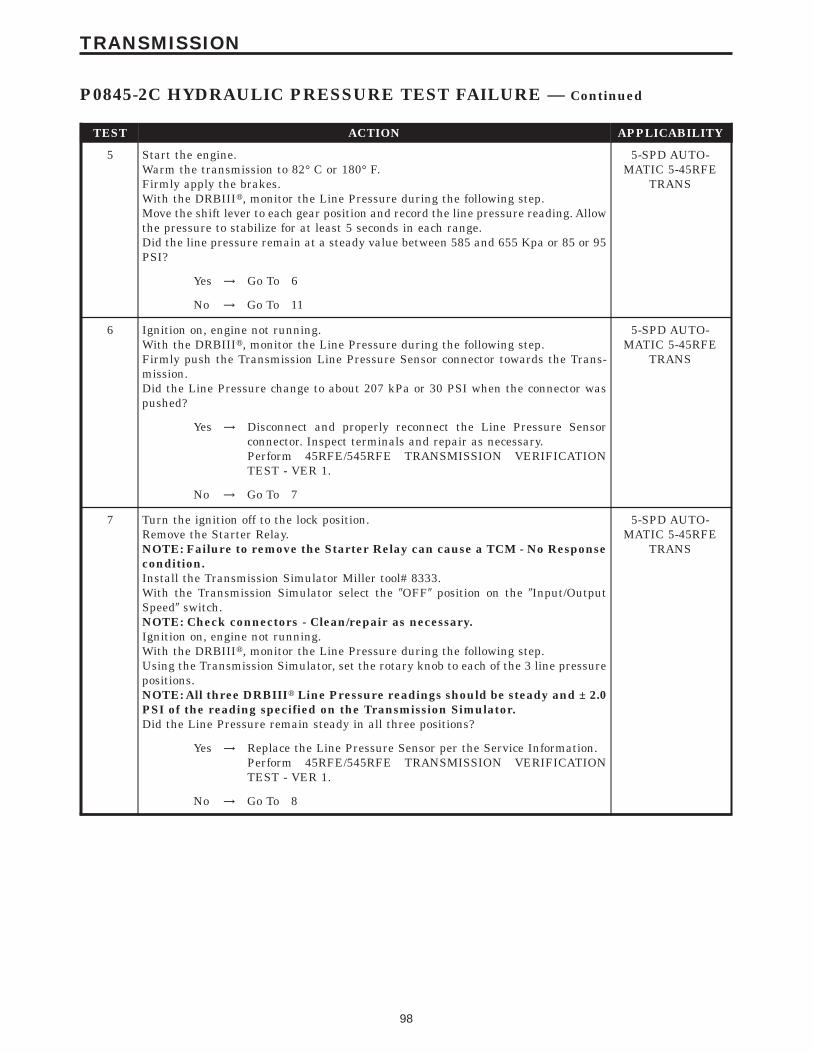
TEST ACTION APPLICABILITY
5 Start the engine.Warm the transmission to 82° C or 180° F.Firmly apply the brakes.With the DRBIIIt, monitor the Line Pressure during the following step.Move the shift lever to each gear position and record the line pressure reading. Allowthe pressure to stabilize for at least 5 seconds in each range.Did the line pressure remain at a steady value between 585 and 655 Kpa or 85 or 95PSI?
5-SPD AUTO-MATIC 5-45RFE
TRANS
Yes → Go To 6
No → Go To 11
6 Ignition on, engine not running.With the DRBIIIt, monitor the Line Pressure during the following step.Firmly push the Transmission Line Pressure Sensor connector towards the Trans-mission.Did the Line Pressure change to about 207 kPa or 30 PSI when the connector waspushed?
5-SPD AUTO-MATIC 5-45RFE
TRANS
Yes → Disconnect and properly reconnect the Line Pressure Sensorconnector. Inspect terminals and repair as necessary.Perform 45RFE/545RFE TRANSMISSION VERIFICATIONTEST - VER 1.
No → Go To 7
7 Turn the ignition off to the lock position.Remove the Starter Relay.NOTE: Failure to remove the Starter Relay can cause a TCM - No Responsecondition.Install the Transmission Simulator Miller tool# 8333.With the Transmission Simulator select the 9OFF9 position on the 9Input/OutputSpeed9 switch.NOTE: Check connectors - Clean/repair as necessary.Ignition on, engine not running.With the DRBIIIt, monitor the Line Pressure during the following step.Using the Transmission Simulator, set the rotary knob to each of the 3 line pressurepositions.NOTE: All three DRBIIIt Line Pressure readings should be steady and ± 2.0PSI of the reading specified on the Transmission Simulator.Did the Line Pressure remain steady in all three positions?
5-SPD AUTO-MATIC 5-45RFE
TRANS
Yes → Replace the Line Pressure Sensor per the Service Information.Perform 45RFE/545RFE TRANSMISSION VERIFICATIONTEST - VER 1.
No → Go To 8
98
TRANSMISSION
P0845-2C HYDRAULIC PRESSURE TEST FAILURE — Continued

TEST ACTION APPLICABILITY
8 Turn the ignition off to the lock position.Disconnect the TCM harness connector.Disconnect the Line Pressure Sensor harness connector.Note: Check connectors - Clean/repair as necessary.Measure the resistance of the 5-volt Supply circuit from the Line Pressure Sensorharness connector to the TCM harness connector.Is the resistance above 5.0 ohms?
5-SPD AUTO-MATIC 5-45RFE
TRANS
Yes → Repair the 5-volt Supply circuit for an open.Perform 45RFE/545RFE TRANSMISSION VERIFICATIONTEST - VER 1.
No → Go To 9
9 Turn the ignition off to the lock position.Disconnect the TCM harness connector.Disconnect the Line Pressure Sensor harness connector.Note: Check connectors - Clean/repair as necessary.Measure the resistance between ground and the 5-volt Supply circuit.Is the resistance below 5.0 ohms?
5-SPD AUTO-MATIC 5-45RFE
TRANS
Yes → Repair the 5-volt Supply circuit for a short to ground.Perform 45RFE/545RFE TRANSMISSION VERIFICATIONTEST - VER 1.
No → Go To 10
10 If there are no possible causes remaining, view repair. 5-SPD AUTO-MATIC 5-45RFE
TRANS
RepairReplace the Transmission Control Module. WITH THE DRBIIItPERFORM QUICK LEARN AND REPROGRAM PINION FAC-TOR.Perform 45RFE/545RFE TRANSMISSION VERIFICATIONTEST - VER 1.
11 Turn the ignition off to the lock position.Remove the Starter Relay.NOTE: Failure to remove the Starter Relay can cause a TCM - No Responsecondition.Install the Transmission Simulator Miller tool# 8333.With the Transmission Simulator Miller tool# 8333, turn the Pressure Switchselector to 2C.Note: Check connectors - Clean/repair as necessary.Ignition on, engine not running.With the DRBIIIt, monitor the 2C Pressure Switch state during the following step.While pressing and holding the Pressure Switch test button, wiggle the wiringharness and connectors pertaining to the 2C Pressure Switch.Did the 2C Pressure Switch state change to closed and remain closed while wigglingthe wires?
5-SPD AUTO-MATIC 5-45RFE
TRANS
Yes → Go To 12
No → Go To 14
99
TRANSMISSION
P0845-2C HYDRAULIC PRESSURE TEST FAILURE — Continued

TEST ACTION APPLICABILITY
12 Remove and inspect the Transmission Oil Pan per the Service Information.Does the Transmission Oil Pan contain excessive debris or contamination?
5-SPD AUTO-MATIC 5-45RFE
TRANS
Yes → Repair the cause of the excessive debris in the Transmission OilPan. Refer to the Service Information for the proper procedures.Perform 45RFE/545RFE TRANSMISSION VERIFICATIONTEST - VER 1.
No → Go To 13
13 If there are no possible causes remaining, view repair. 5-SPD AUTO-MATIC 5-45RFE
TRANS
RepairRepair Internal Transmission as necessary. Disassemble andinspect the Valve Body and repair or replace as necessary. If noproblems are found in the Valve Body, replace the TransmissionSolenoid/TRS Assembly.Perform 45RFE/545RFE TRANSMISSION VERIFICATIONTEST - VER 1.
14 Turn the ignition off to the lock position.Disconnect the TCM harness connector.Disconnect the Transmission Solenoid /TRS Assembly harness connector.Note: Check connectors - Clean/repair as necessary.Measure the resistance of the 2C Pressure Switch Sense circuit from the TCMharness connector to the Transmission Solenoid/TRS Assembly harness connector.Is the resistance above 5.0 ohms?
5-SPD AUTO-MATIC 5-45RFE
TRANS
Yes → Repair the 2C Pressure Switch Sense circuit for an open.Perform 45RFE/545RFE TRANSMISSION VERIFICATIONTEST - VER 1.
No → Go To 15
15 Turn the ignition off to the lock position.Disconnect the Transmission Solenoid/TRS Assembly harness connector.Disconnect the TCM harness connector.Connect a jumper wire between the Fused B(+) circuit and the Transmission ControlRelay Output circuit in the Transmission Control Relay connector.Ignition on, engine not running.Using a 12-volt test light connected to ground, check the Transmission Control RelayOutput circuit in the Transmission Solenoid/TRS Assembly harness connector.NOTE: The test light must illuminate brightly. Compare the brightness tothat of a direct connection to the battery.Does the test light illuminate brightly?
5-SPD AUTO-MATIC 5-45RFE
TRANS
Yes → Go To 16
No → Repair the Transmission Control Relay Output circuit for anopen. If the fuse is open make sure to check for a short to ground.Perform 45RFE/545RFE TRANSMISSION VERIFICATIONTEST - VER 1.
100
TRANSMISSION
P0845-2C HYDRAULIC PRESSURE TEST FAILURE — Continued

TEST ACTION APPLICABILITY
16 Turn the ignition off to the lock position.Disconnect the TCM harness connector.Disconnect the Transmission Solenoid/TRS Assembly harness connector.Note: Check connectors - Clean/repair as necessary.Measure the resistance between ground and the 2C Pressure Switch Sense circuit.Is the resistance below 5.0 ohms?
5-SPD AUTO-MATIC 5-45RFE
TRANS
Yes → Repair the 2C Pressure Switch circuit for a short to ground.Perform 45RFE/545RFE TRANSMISSION VERIFICATIONTEST - VER 1.
No → Go To 17
17 Turn the ignition off to the lock position.Disconnect the TCM harness connector.Disconnect the Transmission Solenoid/TRS Assembly harness connector.Remove the Transmission Control Relay from the PDC.Note: Check connectors - Clean/repair as necessary.Connect a jumper wire between the Fused B+ circuit and the Transmission ControlRelay Output circuit in the Transmission Control Relay connector.Ignition on, engine not running.Measure the voltage of the 2C Pressure Switch Sense circuit in the TCM harnessconnector.Is the voltage above 0.5 volt?
5-SPD AUTO-MATIC 5-45RFE
TRANS
Yes → Repair the 2C Pressure Switch Sense circuit for a short to voltage.Perform 45RFE/545RFE TRANSMISSION VERIFICATIONTEST - VER 1.
No → Go To 18
18 If there are no possible causes remaining, view repair. 5-SPD AUTO-MATIC 5-45RFE
TRANS
RepairReplace the Transmission Control Module. WITH THE DRBIIItPERFORM QUICK LEARNPerform 45RFE/545RFE TRANSMISSION VERIFICATIONTEST - VER 1.
19 The conditions necessary to set this DTC are not present at this time. Using theschematics as a guide, inspect the wiring and connectors specific to this circuit.Wiggle the wires while checking for shorts and open circuits.Were there any problems found?
5-SPD AUTO-MATIC 5-45RFE
TRANS
Yes → Repair as necessary.Perform 45RFE/545RFE TRANSMISSION VERIFICATIONTEST - VER 1.
No → Test Complete.
101
TRANSMISSION
P0845-2C HYDRAULIC PRESSURE TEST FAILURE — Continued

Symptom:P0846-2C PRESSURE SWITCH SENSE CIRCUIT
When Monitored and Set Condition:
P0846-2C PRESSURE SWITCH SENSE CIRCUIT
When Monitored: Whenever the engine is running.
Set Condition: The appropriate code is set if one of the pressure switches are open orclosed at the wrong time in a given gear .
POSSIBLE CAUSES
RELATED RELAY DTC’S PRESENT
INTERMITTENT CONDITIONS
2C PRESSURE SWITCH SENSE CIRCUIT OPEN
TRANSMISSION CONTROL RELAY OUTPUT CIRCUIT OPEN
2C PRESSURE SWITCH SENSE CIRCUIT SHORT TO GROUND
2C PRESSURE SWITCH SENSE CIRCUIT SHORT TO VOLTAGE
2C PRESSURE SWITCH
TCM - 2C PRESSURE SWITCH
TEST ACTION APPLICABILITY
1 NOTE: Low fluid level can be the cause of many transmission problems. Ifthe fluid level is low locate and repair the leak then check and adjust thefluid level per the service information.NOTE: Always perform diagnostics with a fully charged battery to avoidfalse symptoms.With the DRBIIIt, read the engine DTC’s. Check and repair all engine DTC’s priorto performing transmission symptom diagnostics.With the DRBIIIt, read Transmission DTC’s. Record all DTC’s and 1 Trip Failures.NOTE: Diagnose 1 Trip Failures as a fully matured DTC.Using the wiring diagram/schematic as a guide, inspect the wiring and connectors.Repair as necessary.Perform the Shift Lever Position Test. If the test does not pass, refer to Symptom testfor P0706 Check Shifter Signal.For Gear Ratio DTC’s, check and record all CVI’s.Most DTC’s set on start up but some must be set by driving the vehicle such that alldiagnostic monitors have run.Note: Verify flash level of transmission controller. Some problems arecorrected by software upgrades to the transmission controller.NOTE: Check for applicable TSB’s related to the problem.Perform this procedure prior to Symptom diagnosis.
All
ContinueGo To 2
102
TRANSMISSION

TEST ACTION APPLICABILITY
2 With the DRBIIIt, check for other transmission DTC’s.Are there any Transmission Control Relay related DTC’s P0890, P0891, or P0888present?
5-SPD AUTO-MATIC 5-45RFE
TRANS
Yes → Refer to symptom list and perform test for Transmission ControlRelay related DTCs.Perform 45RFE/545RFE TRANSMISSION VERIFICATIONTEST - VER 1.
No → Go To 3
3 With the DRBIIIt, Check the STARTS SINCE SET counter.NOTE: This counter only applies to the last DTC set.Is the STARTS SINCE SET counter for P0846, 2 or less?
5-SPD AUTO-MATIC 5-45RFE
TRANS
Yes → Go To 4
No → Go To 11
4 Turn the ignition off to the lock position.Remove the Starter Relay from the PDC.NOTE: Failure to remove the Starter Relay can cause a TCM - No Responsecondition.Install the Transmission Simulator, Miller tool #8333.Note: Check connectors - Clean/repair as necessary.Ignition on, engine not running.With the Transmission Simulator, turn the Pressure Switch selector switch on 2C.With the DRBIIIt, monitor the 2C Pressure Switch while pressing the PressureSwitch test button on the Transmission Simulator.Did the state of the 2C Pressure Switch change while pressing the Pressure SwitchTest button?
5-SPD AUTO-MATIC 5-45RFE
TRANS
Yes → Go To 5
No → Go To 6
5 If there are no possible causes remaining, view repair. 5-SPD AUTO-MATIC 5-45RFE
TRANS
RepairReplace the Transmission Solenoid/TRS Assembly per the ServiceInformation.Perform 45RFE/545RFE TRANSMISSION VERIFICATIONTEST - VER 1.
6 Turn the ignition off to the lock position.Disconnect the TCM harness connector.Disconnect the Transmission Solenoid /TRS Assembly harness connector.Note: Check connectors - Clean/repair as necessary.Measure the resistance of the 2C Pressure Switch Sense circuit from the TCMharness connector to the Transmission Solenoid/TRS Assembly harness connector.Is the resistance above 5.0 ohms?
5-SPD AUTO-MATIC 5-45RFE
TRANS
Yes → Repair the 2C Pressure Switch Sense circuit for an open.Perform 45RFE/545RFE TRANSMISSION VERIFICATIONTEST - VER 1.
No → Go To 7
103
TRANSMISSION
P0846-2C PRESSURE SWITCH SENSE CIRCUIT — Continued

TEST ACTION APPLICABILITY
7 Turn the ignition off to the lock position.Disconnect the Transmission Solenoid/TRS Assembly harness connector.Ignition on, engine not running.Using a 12-volt test light connected to ground, check the Transmission Control RelayOutput circuit in the Solenoid/TRS Assembly harness connector.NOTE: The test light must illuminate brightly. Compare the brightness tothat of a direct connection to the battery.Does the test light illuminate brightly?
5-SPD AUTO-MATIC 5-45RFE
TRANS
Yes → Go To 8
No → Repair the Transmission Control Relay Output circuit for anopen. If the fuse is open make sure to check for a short to ground.Perform 45RFE/545RFE TRANSMISSION VERIFICATIONTEST - VER 1.
8 Turn the ignition off to the lock position.Disconnect the TCM harness connector.Disconnect the Transmission Solenoid/TRS Assembly harness connector.Note: Check connectors - Clean/repair as necessary.Measure the resistance between ground and the 2C Pressure Switch Sense circuit.Is the resistance below 5.0 ohms?
5-SPD AUTO-MATIC 5-45RFE
TRANS
Yes → Repair the 2C Pressure Switch Sense circuit for a short to ground.Perform 45RFE/545RFE TRANSMISSION VERIFICATIONTEST - VER 1.
No → Go To 9
9 Turn the ignition off to the lock position.Disconnect the TCM harness connector.Disconnect the Transmission Solenoid/TRS Assembly harness connector.Remove the Transmission Control Relay from the PDC.Note: Check connectors - Clean/repair as necessary.Connect a jumper wire between the Fused B+ circuit and the Transmission ControlRelay Output circuit in the Transmission Control Relay connector.Ignition on, engine not running.Measure the voltage of the 2C Pressure Switch Sense circuit in the TCM harnessconnector.Is the voltage above 0.5 volt?
5-SPD AUTO-MATIC 5-45RFE
TRANS
Yes → Repair the 2C Pressure Switch Sense circuit for a short to voltage.Perform 45RFE/545RFE TRANSMISSION VERIFICATIONTEST - VER 1.
No → Go To 10
10 If there are no possible causes remaining, view repair. 5-SPD AUTO-MATIC 5-45RFE
TRANS
RepairReplace the Transmission Control Module. WITH THE DRBIIItPERFORM QUICK LEARNPerform 45RFE/545RFE TRANSMISSION VERIFICATIONTEST - VER 1.
104
TRANSMISSION
P0846-2C PRESSURE SWITCH SENSE CIRCUIT — Continued

TEST ACTION APPLICABILITY
11 The conditions necessary to set this DTC are not present at this time.Using the schematics as a guide, inspect the wiring and connectors specific to thiscircuit.Wiggle the wires while checking for shorts and open circuits.Check for a Sump filter not installed correctlyReverse carrier snap ring dislodged ( typically sets on heavy throttle accelerationfrom a dead stop)Were there any problems found?
5-SPD AUTO-MATIC 5-45RFE
TRANS
Yes → Repair as necessary.Perform 45RFE/545RFE TRANSMISSION VERIFICATIONTEST - VER 1.
No → Test Complete.
105
TRANSMISSION
P0846-2C PRESSURE SWITCH SENSE CIRCUIT — Continued

Symptom:P0867-LINE PRESSURE FAULT
When Monitored and Set Condition:
P0867-LINE PRESSURE FAULT
When Monitored: Continuously while driving in a forward gear.
Set Condition: The TCM continuously monitors Actual Line Pressure and compares it toDesired Line Pressure. If the difference between Actual Line Pressure and Desired LinePressure is 10 PSI or greater, this code will be set.
POSSIBLE CAUSES
RELATED DTC’S PRESENT
INTERMITTENT WIRING AND CONNECTORS
POOR CONNECTION OR WIRING
TRANSMISSION - LINE PRESSURE OUT OF RANGE
TCM - LINE PRESSURE OUT OF RANGE
TEST ACTION APPLICABILITY
1 NOTE: Low fluid level can be the cause of many transmission problems. Ifthe fluid level is low locate and repair the leak then check and adjust thefluid level per the service information.NOTE: Always perform diagnostics with a fully charged battery to avoidfalse symptoms.With the DRBIIIt, read the engine DTC’s. Check and repair all engine DTC’s priorto performing transmission symptom diagnostics.With the DRBIIIt, read Transmission DTC’s. Record all DTC’s and 1 Trip Failures.NOTE: Diagnose 1 Trip Failures as a fully matured DTC.Using the wiring diagram/schematic as a guide, inspect the wiring and connectors.Repair as necessary.Perform the Shift Lever Position Test. If the test does not pass, refer to Symptom testfor P0706 Check Shifter Signal.For Gear Ratio DTC’s, check and record all CVI’s.Most DTC’s set on start up but some must be set by driving the vehicle such that alldiagnostic monitors have run.Note: Verify flash level of transmission controller. Some problems arecorrected by software upgrades to the transmission controller.NOTE: Check for applicable TSB’s related to the problem.Perform this procedure prior to Symptom diagnosis.
All
ContinueGo To 2
106
TRANSMISSION

TEST ACTION APPLICABILITY
2 With the DRBIIIt, check for other transmission DTC’s.Are there any other line pressure related DTC’s P0932, P0868, or P0869 present?
5-SPD AUTO-MATIC 5-45RFE
TRANS
Yes → Refer to symptom list and perform test for other line pressurerelated DTC’s. Run test for P0932 first if present.Perform 45RFE/545RFE TRANSMISSION VERIFICATIONTEST - VER 1.
No → Go To 3
3 CAUTION: Apply Parking BrakeStart the engine.CAUTION: Firmly apply the brakes.With the DRBIIIt, monitor the Line Pressure, Desired Line Pressure and the TPSDegrees.While firmly applying the brakes place shifter in the R position. Then slowly pressthe accelerator pedal to TPS degree of 15.Compare the Line Pressure reading to the Desired Line Pressure reading on theDRBIIIt.Does the Line Pressure and Desired Line Pressure stay within ± 34 kPa or 5 PSI?
5-SPD AUTO-MATIC 5-45RFE
TRANS
No → Go To 4
Yes → Go To 8
4 With the DRBIIIt, monitor the Line Pressure Sensor voltage while wiggling thewiring harness and connectors pertaining to the Line Pressure Sensor and theSolenoid/TRS assembly.Did the voltage remain steady while wiggling the wiring harness and connectors?
5-SPD AUTO-MATIC 5-45RFE
TRANS
Yes → Go To 5
No → Repair as necessary.Perform 45RFE/545RFE TRANSMISSION VERIFICATIONTEST - VER 1.
5 Turn the ignition off to the lock position.Remove the Starter Relay from the PDC.NOTE: Failure to remove the Starter Relay can cause a TCM - No Responsecondition.Install Transmission Simulator Miller tool #8333.With the Transmission Simulator select the 9OFF9 position on the 9Input/OutputSpeed9 switch.Ignition on, engine not running.With the DRBIIIt, monitor the Line Pressure during the following step.Using the Transmission Simulator, turn the selector switch to each of the 3 LinePressure positions.NOTE: All three DRBIIIt Line Pressure readings should be steady and ± 2.0PSI of the reading specified on the Transmission Simulator.Does the Line Pressure fluctuate up and down more than 69 kPa or 10 PSI at any ofthe positions?
5-SPD AUTO-MATIC 5-45RFE
TRANS
Yes → Go To 6
No → Go To 7
107
TRANSMISSION
P0867-LINE PRESSURE FAULT — Continued

TEST ACTION APPLICABILITY
6 If there are no possible causes remaining, view repair. 5-SPD AUTO-MATIC 5-45RFE
TRANS
RepairReplace the Transmission Control Module. WITH THE DRBIIItPERFORM QUICK LEARN.Perform 45RFE/545RFE TRANSMISSION VERIFICATIONTEST - VER 1.
7 If there are no possible causes remaining, view repair. 5-SPD AUTO-MATIC 5-45RFE
TRANS
RepairIf the transmission is to be repaired, inspect the oil pump perService Manual information and replace if necessary. If no prob-lem is found, replace the Solenoid/TRS assembly - stuck PressureControl Solenoid.Perform 45RFE/545RFE TRANSMISSION VERIFICATIONTEST - VER 1.
8 The conditions necessary to set this DTC are not present at this time. Using theschematics as a guide, inspect the wiring and connectors specific to this circuit.Wiggle the wires while checking for shorts and open circuits.Where there any problems found?
5-SPD AUTO-MATIC 5-45RFE
TRANS
Yes → Repair as necessary.Perform 45RFE/545RFE TRANSMISSION VERIFICATIONTEST - VER 1.
No → Test Complete.
108
TRANSMISSION
P0867-LINE PRESSURE FAULT — Continued

Symptom:P0868-LINE PRESSURE LOW
When Monitored and Set Condition:
P0868-LINE PRESSURE LOW
When Monitored: Continuously while driving in a forward gear.
Set Condition: The TCM continuously monitors Actual Line Pressure and compares it toDesired Line Pressure. If Actual Line Pressure is more than 10 PSI below Desired LinePressure, this code will be set.
POSSIBLE CAUSES
CHECK FOR RELATED DTC’S
TCM AND WIRING - LOW LINE PRESSURE
INTERMITTENT WIRING AND CONNECTORS
5 VOLT SUPPLY CIRCUIT OPEN
POOR LINE PRESSURE SENSOR CONNECTION
5 VOLT SUPPLY CIRCUIT SHORT TO GROUND
5 VOLT SUPPLY CIRCUIT SHORT TO VOLTAGE
PRESSURE CONTROL SOLENOID CONTROL CIRCUIT SHORT TO VOLTAGE
INTERNAL TRANSMISSION - LINE PRESSURE LOW
LINE PRESSURE SENSOR - CALIBRATION OUT OF LIMITS
PLUGGED FILTER
TCM - LINE PRESSURE LOW
109
TRANSMISSION

TEST ACTION APPLICABILITY
1 NOTE: Low fluid level can be the cause of many transmission problems. Ifthe fluid level is low locate and repair the leak then check and adjust thefluid level per the service information.NOTE: Always perform diagnostics with a fully charged battery to avoidfalse symptoms.With the DRBIIIt, read the engine DTC’s. Check and repair all engine DTC’s priorto performing transmission symptom diagnostics.With the DRBIIIt, read Transmission DTC’s. Record all DTC’s and 1 Trip Failures.NOTE: Diagnose 1 Trip Failures as a fully matured DTC.Using the wiring diagram/schematic as a guide, inspect the wiring and connectors.Repair as necessary.Perform the Shift Lever Position Test. If the test does not pass, refer to Symptom testfor P0706 Check Shifter Signal.For Gear Ratio DTC’s, check and record all CVI’s.Most DTC’s set on start up but some must be set by driving the vehicle such that alldiagnostic monitors have run.Note: Verify flash level of transmission controller. Some problems arecorrected by software upgrades to the transmission controller.NOTE: Check for applicable TSB’s related to the problem.Perform this procedure prior to Symptom diagnosis.
All
ContinueGo To 2
2 With the DRBIIIt, check for other transmission DTC’sIs the DTC P0932 present also?
5-SPD AUTO-MATIC 5-45RFE
TRANS
Yes → Refer to symptom list for problems related to P0932.Perform 45RFE/545RFE TRANSMISSION VERIFICATIONTEST - VER 1.
No → Go To 3
3 With the DRBIIIt, check the STARTS SINCE SET counter for P0868.NOTE: This counter only applies to the last DTC set.Is the START SINCE SET COUNTER 2 or less?
5-SPD AUTO-MATIC 5-45RFE
TRANS
Yes → Go To 4
No → Go To 14
4 Ignition on, engine not running.With the DRBIIIt, monitor the Line Pressure, firmly push the Line Pressure Sensorharness connector towards the Transmission.Did the Line Pressure change to about 207 kPa or 30 PSI when the connector waspushed?
5-SPD AUTO-MATIC 5-45RFE
TRANS
Yes → Disconnect and properly reconnect the Line Pressure Sensorconnector. Inspect terminals and repair as necessary.Perform 45RFE/545RFE TRANSMISSION VERIFICATIONTEST - VER 1.
No → Go To 5
110
TRANSMISSION
P0868-LINE PRESSURE LOW — Continued

TEST ACTION APPLICABILITY
5 Turn the ignition off to the lock position.Remove the Starter Relay.NOTE: Failure to remove the Starter Relay can cause a TCM - No Responsecondition.Install the Transmission Simulator Miller tool# 8333.With the Transmission Simulator select the 9OFF9 position on the 9Input/OutputSpeed9 switch.NOTE: Check connectors - Clean/repair as necessary.Ignition on, engine not running.With the DRBIIIt, monitor the Line Pressure during the following step.Using the Transmission Simulator, set the rotary knob to each of the 3 line pressurepositions.NOTE: All three DRBIIIt Line Pressure readings should be steady and ± 2.0PSI of the reading specified on the Transmission Simulator.Did the Line Pressure remain steady in all three positions?
5-SPD AUTO-MATIC 5-45RFE
TRANS
Yes → Go To 6
No → Go To 9
6 Turn the ignition off to the lock position.Install the Line Pressure Adaptor, Miller tool# 8259, and the Pressure Gage, Millertool# C-3293, 0 to 2000 kPa or 0 to 300 PSI.Start the engine in park.With the DRBIIIt monitor the Line Pressure.Monitor the reading on the Pressure Gage Miller tool# C-3293.Compare the Line Pressure readings between the DRBIIIt and the Pressure Gage.Is the Line Pressure Gauge reading within 34 kPa or 5 PSI of the DRBIIIt reading?
5-SPD AUTO-MATIC 5-45RFE
TRANS
Yes → Go To 7
No → Replace the Line Pressure Sensor per the Service Information.Perform 45RFE/545RFE TRANSMISSION VERIFICATIONTEST - VER 1.
7 Remove and inspect the Transmission Oil Pan for excessive debris per the ServiceInformation.Remove and inspect the Primary Oil Filter per the Service Information.NOTE: Make sure the Primary Transmission Oil Filter and/or O-ring is notcracked or split.Does the Oil Pan contain excessive debris and/or is the Primary Oil Filter cracked orplugged?
5-SPD AUTO-MATIC 5-45RFE
TRANS
Yes → Repair the plugged, cracked, or split Primary Transmission OilFilter and/or O-ring. If the Primary Transmission Oil Filter isplugged refer to the Service Information for the proper Hydraulicrepair procedure.Perform 45RFE/545RFE TRANSMISSION VERIFICATIONTEST - VER 1.
No → Go To 8
111
TRANSMISSION
P0868-LINE PRESSURE LOW — Continued

TEST ACTION APPLICABILITY
8 If there are no possible causes remaining, view repair. 5-SPD AUTO-MATIC 5-45RFE
TRANS
RepairRepair internal transmission problem. If the transmission is to berepaired, inspect the oil pump per the Service Information andreplace if necessary. If no problem is found, replace the Solenoid/TRS assembly.Perform 45RFE/545RFE TRANSMISSION VERIFICATIONTEST - VER 1.
9 Turn the ignition off to the lock position.Disconnect the TCM harness connector.Disconnect the Line Pressure Sensor harness connector.Note: Check connectors - Clean/repair as necessary.Measure the resistance of the 5-volt Supply circuit from the Line Pressure Sensorharness connector to the TCM harness connector.Is the resistance above 5.0 ohms?
5-SPD AUTO-MATIC 5-45RFE
TRANS
Yes → Repair the 5-volt Supply circuit for an open.Perform 45RFE/545RFE TRANSMISSION VERIFICATIONTEST - VER 1.
No → Go To 10
10 Turn the ignition off to the lock position.Disconnect the TCM harness connector.Disconnect the Line Pressure Sensor harness connector.Note: Check connectors - Clean/repair as necessary.Measure the resistance between ground and the 5-volt Supply circuit.Is the resistance Below 5.0 ohms?
5-SPD AUTO-MATIC 5-45RFE
TRANS
Yes → Repair the 5-volt Supply circuit for a short to ground.Perform 45RFE/545RFE TRANSMISSION VERIFICATIONTEST - VER 1.
No → Go To 11
11 Turn the ignition off to the lock position.Disconnect the TCM harness connector.Remove the Transmission Control Relay from the PDC.Place a jumper wire between the Fused B+ circuit and the Transmission ControlRelay Output circuit in the Transmission Control Relay connector.Ignition on, engine not running.Note: Check connectors - Clean/repair as necessary.Measure the voltage of the 5-volt Supply circuit in the TCM harness connector.Is the voltage above 5.5 volts?
5-SPD AUTO-MATIC 5-45RFE
TRANS
Yes → Repair the 5-volt Supply circuit for a short to voltage.Perform 45RFE/545RFE TRANSMISSION VERIFICATIONTEST - VER 1.
No → Go To 12
112
TRANSMISSION
P0868-LINE PRESSURE LOW — Continued

TEST ACTION APPLICABILITY
12 Turn the ignition off to the lock position.Disconnect the TCM harness connector.Disconnect the Transmission Solenoid/TRS harness connector.Remove the Transmission Control Relay from the PDC.Note: Check connectors - Clean/repair as necessary.Connect a jumper wire between the Fused B(+) circuit and the Trans Relay Outputcircuit in the relay connector.Ignition on, engine not running.Measure the voltage of the Pressure Control Solenoid control circuit in the TCMharness connector.Is the voltage above 0.5 volts?
5-SPD AUTO-MATIC 5-45RFE
TRANS
Yes → Repair the Pressure Control Solenoid Control circuit for a short tovoltage.Perform 45RFE/545RFE TRANSMISSION VERIFICATIONTEST - VER 1.
No → Go To 13
13 If there are no possible causes remaining, view repair. 5-SPD AUTO-MATIC 5-45RFE
TRANS
RepairReplace the Transmission Control Module. WITH THE DRBIIItPERFORM QUICK LEARNPerform 45RFE/545RFE TRANSMISSION VERIFICATIONTEST - VER 1.
14 The conditions necessary to set this DTC are not present at this time.Using the schematics as a guide, inspect the wiring and connectors specific to thiscircuit.Wiggle the wires while checking for shorts and open circuits.Were there any problems found?
5-SPD AUTO-MATIC 5-45RFE
TRANS
Yes → Repair as necessary.Perform 45RFE/545RFE TRANSMISSION VERIFICATIONTEST - VER 1.
No → Test Complete.
113
TRANSMISSION
P0868-LINE PRESSURE LOW — Continued

Symptom:P0869-LINE PRESSURE HIGH
When Monitored and Set Condition:
P0869-LINE PRESSURE HIGH
When Monitored: Continuously while driving in a forward gear.
Set Condition: The TCM continuously monitors Actual Line Pressure and compares it toDesired Line Pressure. If Actual Line Pressure is more than 10 PSI above Desired LinePressure, this code will be set.
POSSIBLE CAUSES
CHECK FOR RELATED DTC’S
TCM AND WIRING - LINE PRESSURE HIGH
INTERMITTENT WIRING AND CONNECTORS
5-VOLT SUPPLY CIRCUIT OPEN
POOR LINE PRESSURE SENSOR CONNECTION
PRESSURE CONTROL SOLENOID CONTROL CIRCUIT OPEN
5-VOLT SUPPLY CIRCUIT SHORT TO GROUND
PRESSURE CONTROL SOLENOID CONTROL CIRCUIT SHORT TO GROUND
INTERNAL TRANSMISSION - LINE PRESSURE HIGH
LINE PRESSURE SENSOR - CALIBRATION OUT OF LIMITS
TCM - LINE PRESSURE HIGH
114
TRANSMISSION

TEST ACTION APPLICABILITY
1 NOTE: Low fluid level can be the cause of many transmission problems. Ifthe fluid level is low locate and repair the leak then check and adjust thefluid level per the service information.NOTE: Always perform diagnostics with a fully charged battery to avoidfalse symptoms.With the DRBIIIt, read the engine DTC’s. Check and repair all engine DTC’s priorto performing transmission symptom diagnostics.With the DRBIIIt, read Transmission DTC’s. Record all DTC’s and 1 Trip Failures.NOTE: Diagnose 1 Trip Failures as a fully matured DTC.Using the wiring diagram/schematic as a guide, inspect the wiring and connectors.Repair as necessary.Perform the Shift Lever Position Test. If the test does not pass, refer to Symptom testfor P0706 Check Shifter Signal.For Gear Ratio DTC’s, check and record all CVI’s.Most DTC’s set on start up but some must be set by driving the vehicle such that alldiagnostic monitors have run.Note: Verify flash level of transmission controller. Some problems arecorrected by software upgrades to the transmission controller.NOTE: Check for applicable TSB’s related to the problem.Perform this procedure prior to Symptom diagnosis.
All
ContinueGo To 2
2 With the DRBIIIt, check for other Transmission DTC’sIs the DTC P0932 present also?
5-SPD AUTO-MATIC 5-45RFE
TRANS
Yes → Refer to symptom list for problems related to P0932.Perform 45RFE/545RFE TRANSMISSION VERIFICATIONTEST - VER 1.
No → Go To 3
3 The transmission temperature must be at least 180 degrees for the results of this testto be valid.With the DRBIIIt, check the STARTS SINCE SET counter for P0869.Is the STARTS SINCE SET COUNTER 2 or less?
5-SPD AUTO-MATIC 5-45RFE
TRANS
Yes → Go To 4
No → Go To 13
4 Ignition on, engine not running.With the DRBIIIt, monitor the Transmission Line Pressure.Firmly push the Line Pressure Sensor harness connector inward towards theTransmission.Did the Line Pressure change to about 207 kPa or 30 PSI when the sensor connectorwas pushed?
5-SPD AUTO-MATIC 5-45RFE
TRANS
Yes → Disconnect and properly reconnect the Line Pressure Sensorconnector. Inspect terminals and repair as necessary.Perform 45RFE/545RFE TRANSMISSION VERIFICATIONTEST - VER 1.
No → Go To 5
115
TRANSMISSION
P0869-LINE PRESSURE HIGH — Continued

TEST ACTION APPLICABILITY
5 Turn the ignition off to the lock position.Remove the Starter Relay.NOTE: Failure to remove the Starter Relay can cause a TCM - No Responsecondition.Install the Transmission Simulator Miller tool# 8333.With the Transmission Simulator select the 9OFF9 position on the 9Input/OutputSpeed9 switch.NOTE: Check connectors - Clean/repair as necessary.Ignition on, engine not running.With the DRBIIIt, monitor the Line Pressure during the following step.Using the Transmission Simulator, set the rotary knob to each of the 3 line pressurepositions.NOTE: All three DRBIIIt Line Pressure readings should be steady and ± 2.0PSI of the reading specified on the Transmission Simulator.Did the Line Pressure remain steady in all three positions?
5-SPD AUTO-MATIC 5-45RFE
TRANS
Yes → Go To 6
No → Go To 8
6 Turn the ignition off to the lock position.Install the Line Pressure Adaptor, Miller tool# 8259, and the Pressure Gage, Millertool# C-3293, 0 to 2000 kPa or 0 to 300 PSI.Start the engine in park.With the DRBIIIt, monitor the Line Pressure.Monitor the reading on the Pressure Gage, Miller tool# C-3293.Compare the Line Pressure reading between the DRBIIIt and the Pressure Gage.Is the Pressure Gauge reading within 34 kPa or 5 PSI of the DRBIIIt reading?
5-SPD AUTO-MATIC 5-45RFE
TRANS
Yes → Go To 7
No → Replace the Line Pressure Sensor.Perform 45RFE/545RFE TRANSMISSION VERIFICATIONTEST - VER 1.
7 If there are no possible causes remaining, view repair. 5-SPD AUTO-MATIC 5-45RFE
TRANS
RepairIf the transmission is to be repaired, inspect the oil pump per theService Information and replace if necessary. If no problem isfound, replace the Solenoid/TRS assembly - stuck Pressure Con-trol Solenoid.Perform 45RFE/545RFE TRANSMISSION VERIFICATIONTEST - VER 1.
8 Turn the ignition off to the lock position.Disconnect the Transmission Control Module harness connector.Disconnect the Line Pressure Sensor harness connector.Note: Check connectors - Clean/repair as necessary.Measure the resistance of the 5-volt Supply circuit from the Line Pressure Sensorharness connector to the Transmission Control Module harness connector.Is the resistance above 5.0 ohms?
5-SPD AUTO-MATIC 5-45RFE
TRANS
Yes → Repair the 5-volt Supply circuit for an open.Perform 45RFE/545RFE TRANSMISSION VERIFICATIONTEST - VER 1.
No → Go To 9
116
TRANSMISSION
P0869-LINE PRESSURE HIGH — Continued

TEST ACTION APPLICABILITY
9 Turn the ignition off to the lock position.Disconnect the Transmission Control Module harness connector.Disconnect the Transmission Solenoid /TRS harness connectorNote: Check connectors - Clean/repair as necessary.Measure the resistance of the Pressure Control Solenoid Control circuit from theTransmission Control Module harness connector to the Solenoid/TRS harness con-nector.Is the resistance above 5.0 ohms?
5-SPD AUTO-MATIC 5-45RFE
TRANS
Yes → Repair the Pressure Control Solenoid Control circuit for an open.Perform 45RFE/545RFE TRANSMISSION VERIFICATIONTEST - VER 1.
No → Go To 10
10 Turn the ignition off to the lock position.Disconnect the TCM harness connector.Disconnect the Line Pressure Sensor harness connector.Note: Check connectors - Clean/repair as necessary.Measure the resistance between ground and the 5-volt Supply circuit.Is the resistance below 5.0 ohms?
5-SPD AUTO-MATIC 5-45RFE
TRANS
Yes → Repair the 5-volt Supply circuit for a short to ground.Perform 45RFE/545RFE TRANSMISSION VERIFICATIONTEST - VER 1.
No → Go To 11
11 Turn the ignition off to the lock position.Disconnect the Transmission Control Module harness connector.Disconnect the Transmission Solenoid/TRS harness connector.Note: Check connectors - Clean/repair as necessary.Measure the resistance between ground and the Pressure Control Solenoid Controlcircuit.Is the resistance below 5.0 ohms?
5-SPD AUTO-MATIC 5-45RFE
TRANS
Yes → Repair the Pressure Control Solenoid Control circuit for a short toground.Perform 45RFE/545RFE TRANSMISSION VERIFICATIONTEST - VER 1.
No → Go To 12
12 If there are no possible causes remaining, view repair. 5-SPD AUTO-MATIC 5-45RFE
TRANS
RepairReplace the Transmission Control Module. WITH THE DRBIIItPERFORM QUICK LEARNPerform 45RFE/545RFE TRANSMISSION VERIFICATIONTEST - VER 1.
117
TRANSMISSION
P0869-LINE PRESSURE HIGH — Continued

TEST ACTION APPLICABILITY
13 The conditions necessary to set this DTC are not present at this time.Using the schematics as a guide, inspect the wiring and connectors specific to thiscircuit.Wiggle the wires while checking for shorts and open circuits.Were there any problems found?
5-SPD AUTO-MATIC 5-45RFE
TRANS
Yes → Repair as necessary.Perform 45RFE/545RFE TRANSMISSION VERIFICATIONTEST - VER 1.
No → Test Complete.
118
TRANSMISSION
P0869-LINE PRESSURE HIGH — Continued

Symptom:P0870-OD HYDRAULIC PRESSURE TEST FAILURE
When Monitored and Set Condition:
P0870-OD HYDRAULIC PRESSURE TEST FAILURE
When Monitored: In any forward gear with engine speed above 1000 RPM shortly aftera shift and every minute thereafter.
Set Condition: After a shift into a forward gear, with engine speed above 1000 RPM, theTCM momentarily turns on element pressure to the clutch circuits that don’t havepressure to identify the correct pressure switch closes. If the pressure switch does not close2 times the DTC sets.
POSSIBLE CAUSES
RELATED LINE PRESSURE DTC’S PRESENT
RELATED SPEED RATIO AND/OR PRESSURE SWITCH DTC’S PRESENT
TCM AND WIRING - LOW LINE PRESSURE
INTERMITTENT WIRING & CONNECTORS
5-VOLT SUPPLY CIRCUIT OPEN
OD PRESSURE SWITCH SENSE CIRCUIT OPEN
POOR LINE PRESSURE SENSOR CONNECTION
TRANSMISSION CONTROL RELAY OUTPUT CIRCUIT OPEN
5-VOLT SUPPLY CIRCUIT SHORT TO GROUND
OD PRESSURE SWITCH SENSE CIRCUIT SHORT TO GROUND
OD PRESSURE SWITCH SENSE CIRCUIT SHORT TO VOLTAGE
EXCESSIVE DEBRIS IN OIL PAN
INTERNAL TRANSMISSION PROBLEM - OD PRESSURE TEST
TCM - NO 5 VOLTS - LOW LINE PRESSURE SENSOR
TCM - OD PRESSURE SWITCH
119
TRANSMISSION

TEST ACTION APPLICABILITY
1 NOTE: Low fluid level can be the cause of many transmission problems. Ifthe fluid level is low locate and repair the leak then check and adjust thefluid level per the service information.NOTE: Always perform diagnostics with a fully charged battery to avoidfalse symptoms.With the DRBIIIt, read the engine DTC’s. Check and repair all engine DTC’s priorto performing transmission symptom diagnostics.With the DRBIIIt, read Transmission DTC’s. Record all DTC’s and 1 Trip Failures.NOTE: Diagnose 1 Trip Failures as a fully matured DTC.Using the wiring diagram/schematic as a guide, inspect the wiring and connectors.Repair as necessary.Perform the Shift Lever Position Test. If the test does not pass, refer to Symptom testfor P0706 Check Shifter Signal.For Gear Ratio DTC’s, check and record all CVI’s.Most DTC’s set on start up but some must be set by driving the vehicle such that alldiagnostic monitors have run.Note: Verify flash level of transmission controller. Some problems arecorrected by software upgrades to the transmission controller.NOTE: Check for applicable TSB’s related to the problem.Perform this procedure prior to Symptom diagnosis.
All
ContinueGo To 2
2 With the DRBIIIt, check for other Transmission DTC’sAre there any Line Pressure related DTC’s P0867, P0932, P0868, P0869, or P0944present?
5-SPD AUTO-MATIC 5-45RFE
TRANS
Yes → Refer to symptom list and perform appropriate test.Perform 45RFE/545RFE TRANSMISSION VERIFICATIONTEST - VER 1.
No → Go To 3
3 With the DRBIIIt, check for other Transmission DTC’sIs the DTC P0733 and/or P0871 present also?
5-SPD AUTO-MATIC 5-45RFE
TRANS
Yes → Replace the Transmission Solenoid/TRS Assembly per the ServiceInformation.Perform 45RFE/545RFE TRANSMISSION VERIFICATIONTEST - VER 1.
No → Go To 4
4 With the DRBIIIt, Check the STARTS SINCE SET counter for P0870.NOTE: This counter only applies to the last DTC set.Is the STARTS SINCE SET counter 2 or less?
5-SPD AUTO-MATIC 5-45RFE
TRANS
Yes → Go To 5
No → Go To 19
120
TRANSMISSION
P0870-OD HYDRAULIC PRESSURE TEST FAILURE — Continued

TEST ACTION APPLICABILITY
5 Start engine.Warm transmission to 82° C or 180 ° F.Firmly apply brakes.With the DRBIIIt, monitor the Transmission Line Pressure.Move the shift lever to each gear position and record the Line Pressure reading. Allowthe pressure to stabilize for at least 5 seconds in each range.Did the Line Pressure remain at a steady value between 585 and 655 kPa or 85 and95 PSI?
5-SPD AUTO-MATIC 5-45RFE
TRANS
Yes → Go To 6
No → Go To 11
6 Turn the ignition off to the lock position.Remove the Starter Relay.NOTE: Failure to remove Starter Relay can cause a TCM - No Responsecondition.Install the Transmission Simulator, Miller tool #8333.With the Transmission Simulator select the 9OFF9 position on the 9Input/OutputSpeed9 switch.Ignition on, engine not running.With the DRBIIIt, monitor the Line Pressure during the following step.Using the Transmission Simulator, turn the selector switch to each of the 3 LinePressure positions.NOTE: All three DRBIIIt Line Pressure readings should be steady and ± 2.0PSI of the reading specified on the Transmission Simulator.Did the Line Pressure remain steady in all 3 positions?
5-SPD AUTO-MATIC 5-45RFE
TRANS
Yes → Replace the Line Pressure Sensor per the Service Information.Perform 45RFE/545RFE TRANSMISSION VERIFICATIONTEST - VER 1.
No → Go To 7
7 Ignition on, engine not running.With the DRBIIIt, monitor the Line Pressure while firmly pushing the Line PressureSensor connector towards the Transmission.Did the Line Pressure change to about 207 kPa or 30 PSI when the connector waspushed?
5-SPD AUTO-MATIC 5-45RFE
TRANS
Yes → Disconnect and properly reconnect the Line Pressure Sensorharness connector. Inspect terminals and repair as necessary.Perform 45RFE/545RFE TRANSMISSION VERIFICATIONTEST - VER 1.
No → Go To 8
8 Turn the ignition off to the lock position.Disconnect the TCM harness connector.Disconnect the Line Pressure Sensor harness connector.Note: Check connectors - Clean/repair as necessary.Measure the resistance of the 5-volt Supply circuit from the Line Pressure Sensorharness connector to the TCM harness connector.Is the resistance above 5.0 ohms?
5-SPD AUTO-MATIC 5-45RFE
TRANS
Yes → Repair the 5-volt supply circuit for an open.Perform 45RFE/545RFE TRANSMISSION VERIFICATIONTEST - VER 1.
No → Go To 9
121
TRANSMISSION
P0870-OD HYDRAULIC PRESSURE TEST FAILURE — Continued

TEST ACTION APPLICABILITY
9 Turn the ignition off to the lock position.Disconnect the TCM harness connector.Disconnect the Line Pressure Sensor harness connector.Note: Check connectors - Clean/repair as necessary.Measure the resistance between ground and the 5-volt Supply circuit.Is the resistance below 5.0 ohms?
5-SPD AUTO-MATIC 5-45RFE
TRANS
Yes → Repair the 5-volt Supply circuit for a short to ground.Perform 45RFE/545RFE TRANSMISSION VERIFICATIONTEST - VER 1.
No → Go To 10
10 If there are no possible causes remaining, view repair. 5-SPD AUTO-MATIC 5-45RFE
TRANS
RepairReplace the Transmission Control Module. WITH THE DRBIIItPERFORM QUICK LEARNPerform 45RFE/545RFE TRANSMISSION VERIFICATIONTEST - VER 1.
11 Turn the ignition off to the lock position.Remove the Starter Relay.NOTE: Failure to remove the Starter Relay can cause a TCM - No Responsecondition.Install Transmission Simulator Miller tool #8333.Note: Check connectors - Clean/repair as necessary.Ignition on, engine not running.With the DRBIIIt, monitor the OD Pressure Switch state during the following steps.With the Transmission Simulator Miller tool# 8333, place the selector switch on OD.While pressing the Pressure Switch test button, wiggle the wiring harness andconnectors pertaining to the OD Pressure Switch.Did the OD pressure switch state change to closed and remain closed while wigglingthe wires?
5-SPD AUTO-MATIC 5-45RFE
TRANS
Yes → Go To 12
No → Go To 14
12 Remove and inspect the Transmission Oil Pan per the Service Information.Does the Transmission Oil Pan contain excessive debris or contamination?
5-SPD AUTO-MATIC 5-45RFE
TRANS
Yes → Repair the cause of the excessive debris in the Transmission OilPan. Refer to the Service Information for the proper procedures.Perform 45RFE/545RFE TRANSMISSION VERIFICATIONTEST - VER 1.
No → Go To 13
122
TRANSMISSION
P0870-OD HYDRAULIC PRESSURE TEST FAILURE — Continued

TEST ACTION APPLICABILITY
13 If there are no possible causes remaining, view repair. 5-SPD AUTO-MATIC 5-45RFE
TRANS
RepairRepair Internal Transmission as necessary. Disassemble andinspect the Valve Body and repair or replace as necessary. If noproblems are found in the Valve Body, replace the TransmissionSolenoid/TRS Assembly.Perform 45RFE/545RFE TRANSMISSION VERIFICATIONTEST - VER 1.
14 Turn the ignition off to the lock position.Disconnect the TCM harness connector.Disconnect the Transmission Solenoid /TRS Assembly harness connectorNote: Check connectors - Clean/repair as necessary.Measure the resistance of the OD Pressure Switch Sense circuit from the TCMharness connector to the Solenoid/TRS Assembly harness connector.Is the resistance above 5.0 ohms?
5-SPD AUTO-MATIC 5-45RFE
TRANS
Yes → Repair the OD Pressure Switch Sense circuit for an open.Perform 45RFE/545RFE TRANSMISSION VERIFICATIONTEST - VER 1.
No → Go To 15
15 Turn the ignition off to the lock position.Disconnect the Transmission Solenoid/TRS Assembly harness connector.Disconnect the Transmission Control Relay from the PDC.Connect a jumper wire between the Fused B(+) circuit and the Transmission ControlRelay Output circuit in the Transmission Control Relay connector.Ignition on, engine not running.Using a 12-volt test light connected to ground, check the Transmission Control RelayOutput circuit at the Solenoid/TRS Assembly harness connector.NOTE: The test light must illuminate brightly. Compare the brightness tothat of a direct connection to the battery.Does the test light illuminate brightly?
5-SPD AUTO-MATIC 5-45RFE
TRANS
Yes → Go To 16
No → Repair the Transmission Control Relay Output circuit for anopen. If the fuse is open make sure to check for a short to ground.Perform 45RFE/545RFE TRANSMISSION VERIFICATIONTEST - VER 1.
16 Turn the ignition off to the lock position.Disconnect the TCM harness connector.Disconnect the Transmission Solenoid/TRS Assembly harness connector.Note: Check connectors - Clean/repair as necessary.Measure the resistance between ground and the OD Pressure Switch Sense circuit.Is the resistance below 5.0 ohms?
5-SPD AUTO-MATIC 5-45RFE
TRANS
Yes → Repair the OD Pressure Switch circuit for a short to ground.Perform 45RFE/545RFE TRANSMISSION VERIFICATIONTEST - VER 1.
No → Go To 17
123
TRANSMISSION
P0870-OD HYDRAULIC PRESSURE TEST FAILURE — Continued

TEST ACTION APPLICABILITY
17 Turn the ignition off to the lock position.Disconnect the TCM harness connector.Disconnect the Transmission Solenoid/TRS Assembly harness connector.Remove the Transmission Control Relay from the PDC.Note: Check connectors - Clean/repair as necessary.Connect a jumper wire between the Fused B+ circuit and the Transmission ControlRelay Output circuit in the Transmission Control Relay connector.Ignition on, engine not running.Measure the voltage of the OD Pressure Switch Sense circuit in the TCM harnessconnector.Is the voltage above 0.5 volt?
5-SPD AUTO-MATIC 5-45RFE
TRANS
Yes → Repair the OD Pressure Switch Sense circuit for a short tovoltage.Perform 45RFE/545RFE TRANSMISSION VERIFICATIONTEST - VER 1.
No → Go To 18
18 If there are no possible causes remaining, view repair. 5-SPD AUTO-MATIC 5-45RFE
TRANS
RepairReplace the Transmission Control Module. WITH THE DRBIIItPERFORM QUICK LEARNPerform 45RFE/545RFE TRANSMISSION VERIFICATIONTEST - VER 1.
19 The conditions necessary to set this DTC are not present at this time.Using the schematics as a guide, inspect the wiring and connectors specific to thiscircuit.Wiggle the wires while checking for shorts and open circuits.Were any problems found?
5-SPD AUTO-MATIC 5-45RFE
TRANS
Yes → Repair as necessary.Perform 45RFE/545RFE TRANSMISSION VERIFICATIONTEST - VER 1.
No → Test Complete.
124
TRANSMISSION
P0870-OD HYDRAULIC PRESSURE TEST FAILURE — Continued

Symptom:P0871-OD PRESSURE SWITCH SENSE CIRCUIT
When Monitored and Set Condition:
P0871-OD PRESSURE SWITCH SENSE CIRCUIT
When Monitored: Whenever the engine is running.
Set Condition: The appropriate code is set if one of the pressure switches are open orclosed at the wrong time in a given gear.
POSSIBLE CAUSES
RELATED RELAY DTC’S PRESENT
INTERMITTENT WIRING & CONNECTORS
OD PRESSURE SWITCH SENSE CIRCUIT OPEN
TRANSMISSION CONTROL RELAY OUTPUT CIRCUIT OPEN
OD PRESSURE SWITCH SENSE CIRCUIT SHORT TO GROUND
OD PRESSURE SWITCH SENSE CIRCUIT SHORT TO VOLTAGE
OD PRESSURE SWITCH
TCM - OD PRESSURE SWITCH
TEST ACTION APPLICABILITY
1 NOTE: Low fluid level can be the cause of many transmission problems. Ifthe fluid level is low locate and repair the leak then check and adjust thefluid level per the service information.NOTE: Always perform diagnostics with a fully charged battery to avoidfalse symptoms.With the DRBIIIt, read the engine DTC’s. Check and repair all engine DTC’s priorto performing transmission symptom diagnostics.With the DRBIIIt, read Transmission DTC’s. Record all DTC’s and 1 Trip Failures.NOTE: Diagnose 1 Trip Failures as a fully matured DTC.Using the wiring diagram/schematic as a guide, inspect the wiring and connectors.Repair as necessary.Perform the Shift Lever Position Test. If the test does not pass, refer to Symptom testfor P0706 Check Shifter Signal.For Gear Ratio DTC’s, check and record all CVI’s.Most DTC’s set on start up but some must be set by driving the vehicle such that alldiagnostic monitors have run.Note: Verify flash level of transmission controller. Some problems arecorrected by software upgrades to the transmission controller.NOTE: Check for applicable TSB’s related to the problem.Perform this procedure prior to Symptom diagnosis.
All
ContinueGo To 2
125
TRANSMISSION

TEST ACTION APPLICABILITY
2 With the DRBIIIt, check for other transmission DTC’s.Are there any Transmission Control Relay related DTC’s, P0890, P0891, or P0888present?
5-SPD AUTO-MATIC 5-45RFE
TRANS
Yes → Refer to symptom list and perform test for Transmission ControlRelay related DTCs.Perform 45RFE/545RFE TRANSMISSION VERIFICATIONTEST - VER 1.
No → Go To 3
3 Ignition on, engine not running.With the DRBIIIt, Check the STARTS SINCE SET counter for P0871.NOTE: This counter only applies to the last DTC set.Is the STARTS SINCE SET counter 2 or less?
5-SPD AUTO-MATIC 5-45RFE
TRANS
Yes → Go To 4
No → Go To 11
4 Turn the ignition off to the lock position.Remove the Starter Relay from the PDC.NOTE: Failure to remove the Starter Relay can cause a TCM - No Responsecondition.Install Transmission Simulator, Miller tool #8333.Note: Check connectors - Clean/repair as necessary.Ignition on, engine not running.With the Transmission Simulator, turn the Pressure Switch selector switch to OD.With the DRBIIIt, monitor the OD Pressure Switch state while pressing thePressure Switch Test button on the Transmission Simulator.Did the state of the OD Pressure Switch change while pressing the Pressure SwitchTest button?
5-SPD AUTO-MATIC 5-45RFE
TRANS
Yes → Go To 5
No → Go To 6
5 If there are no possible causes remaining, view repair. 5-SPD AUTO-MATIC 5-45RFE
TRANS
RepairReplace the Transmission Solenoid/TRS Assembly per the ServiceInformation.Perform 45RFE/545RFE TRANSMISSION VERIFICATIONTEST - VER 1.
6 Turn the ignition off to the lock position.Disconnect the TCM harness connector.Disconnect the Transmission Solenoid /TRS Assembly harness connectorNOTE: Check connectors - Clean/repair as necessary.Measure the resistance of the OD Pressure Switch Sense circuit from the TCMharness connector to the Solenoid/TRS Assembly harness connector.Is the resistance above 5.0 ohms?
5-SPD AUTO-MATIC 5-45RFE
TRANS
Yes → Repair the OD Pressure Switch Sense circuit for an open.Perform 45RFE/545RFE TRANSMISSION VERIFICATIONTEST - VER 1.
No → Go To 7
126
TRANSMISSION
P0871-OD PRESSURE SWITCH SENSE CIRCUIT — Continued

TEST ACTION APPLICABILITY
7 Turn the ignition off to the lock position.Disconnect the Transmission Solenoid/TRS Assembly harness connector.Ignition on, engine not running.Using a 12-volt test light connected to ground, check the Transmission Relay outputcircuit in the Transmission Solenoid/TRS harness connector.NOTE: The test light must illuminate brightly. Compare the brightness tothat of a direct connection to the battery.Does the test light illuminate brightly?
5-SPD AUTO-MATIC 5-45RFE
TRANS
Yes → Go To 8
No → Repair cause of unlit or dim test light. Open circuit or highresistance in Transmission Relay output circuit.Perform 45RFE/545RFE TRANSMISSION VERIFICATIONTEST - VER 1.
8 Turn the ignition off to the lock position.Disconnect the TCM harness connector.Disconnect the Transmission Solenoid/TRS Assembly harness connector.Note: Check connectors - Clean/repair as necessary.Measure the resistance between ground and the OD Pressure Switch Sense circuit.Is the resistance below 5.0 ohms?
5-SPD AUTO-MATIC 5-45RFE
TRANS
Yes → Repair the OD Pressure Switch Sense circuit for a short toground.Perform 45RFE/545RFE TRANSMISSION VERIFICATIONTEST - VER 1.
No → Go To 9
9 Turn the ignition off to the lock position.Disconnect the TCM harness connector.Disconnect the Transmission Solenoid/TRS Assembly harness connector.Remove the Transmission Control Relay the PDC.Note: Check connectors - Clean/repair as necessary.Connect a jumper wire between the Fused B+ circuit and Transmission Control RelayOutput circuit in the Transmission Control Relay connector.Ignition on, engine not running.Measure the voltage of the OD Pressure Switch Sense circuit at the TCM harnessconnector.Is the voltage above 0.5 volts?
5-SPD AUTO-MATIC 5-45RFE
TRANS
Yes → Repair the OD Pressure Switch Sense circuit for a short tovoltage.Perform 45RFE/545RFE TRANSMISSION VERIFICATIONTEST - VER 1.
No → Go To 10
10 If there are no possible causes remaining, view repair. 5-SPD AUTO-MATIC 5-45RFE
TRANS
RepairReplace the Transmission Control Module. WITH THE DRBIIItPERFORM QUICK LEARNPerform 45RFE/545RFE TRANSMISSION VERIFICATIONTEST - VER 1.
127
TRANSMISSION
P0871-OD PRESSURE SWITCH SENSE CIRCUIT — Continued

TEST ACTION APPLICABILITY
11 The conditions necessary to set this DTC are not present at this time.Using the schematics as a guide, inspect the wiring and connectors specific to thiscircuit.Wiggle the wires while checking for shorts and open circuits.Check for a Sump filter not installed correctlyReverse carrier snap ring dislodged ( typically sets on heavy throttle accelerationfrom a dead stop)Were there any problems found?
5-SPD AUTO-MATIC 5-45RFE
TRANS
Yes → Repair as necessary.Perform 45RFE/545RFE TRANSMISSION VERIFICATIONTEST - VER 1.
No → Test Complete.
128
TRANSMISSION
P0871-OD PRESSURE SWITCH SENSE CIRCUIT — Continued

Symptom:P0875-UD HYDRAULIC PRESSURE TEST FAILURE
When Monitored and Set Condition:
P0875-UD HYDRAULIC PRESSURE TEST FAILURE
When Monitored: In any forward gear with engine speed above 1000 RPM shortly aftera shift and every minute thereafter.
Set Condition: After a shift into a forward gear, with engine speed above 1000 RPM, theTCM momentarily turns on element pressure to the clutch circuits don’t have pressure toidentify the correct pressure switch closes. If the pressure switch does not close 2 times theDTC sets.
POSSIBLE CAUSES
RELATED LINE PRESSURE DTC’S PRESENT
RELATED SPEED RATIO AND/OR PRESSURE SWITCH DTC’S PRESENT
TCM AND WIRING - LOW LINE PRESSURE
INTERMITTENT WIRING AND CONNECTORS
5-VOLT SUPPLY CIRCUIT OPEN
POOR LINE PRESSURE SENSOR CONNECTION
TRANSMISSION CONTROL RELAY OUTPUT CIRCUIT OPEN
UD PRESSURE SWITCH SENSE CIRCUIT OPEN
5-VOLT SUPPLY CIRCUIT SHORT TO GROUND
UD PRESSURE SWITCH CIRCUIT SHORT TO GROUND
UD PRESSURE SWITCH SENSE CIRCUIT SHORT TO VOLTAGE
EXCESSIVE DEBRIS IN OIL PAN
INTERNAL TRANSMISSION - UD PRESSURE TEST
TCM - NO 5 VOLTS - LOW LINE PRESSURE SENSOR
TCM - UD PRESSURE SWITCH
129
TRANSMISSION

TEST ACTION APPLICABILITY
1 NOTE: Low fluid level can be the cause of many transmission problems. Ifthe fluid level is low locate and repair the leak then check and adjust thefluid level per the service information.NOTE: Always perform diagnostics with a fully charged battery to avoidfalse symptoms.With the DRBIIIt, read the engine DTC’s. Check and repair all engine DTC’s priorto performing transmission symptom diagnostics.With the DRBIIIt, read Transmission DTC’s. Record all DTC’s and 1 Trip Failures.NOTE: Diagnose 1 Trip Failures as a fully matured DTC.Using the wiring diagram/schematic as a guide, inspect the wiring and connectors.Repair as necessary.Perform the Shift Lever Position Test. If the test does not pass, refer to Symptom testfor P0706 Check Shifter Signal.For Gear Ratio DTC’s, check and record all CVI’s.Most DTC’s set on start up but some must be set by driving the vehicle such that alldiagnostic monitors have run.Note: Verify flash level of transmission controller. Some problems arecorrected by software upgrades to the transmission controller.NOTE: Check for applicable TSB’s related to the problem.Perform this procedure prior to Symptom diagnosis.
All
ContinueGo To 2
2 With the DRBIIIt, check for other Transmission DTC’sAre there any line pressure related DTC’s, P0867, P0932, P0868, P0869, or P0944present?
5-SPD AUTO-MATIC 5-45RFE
TRANS
Yes → Refer to Symptom List for the related symptom(s).Perform 45RFE/545RFE TRANSMISSION VERIFICATIONTEST - VER 1.
No → Go To 3
3 With the DRBIIIt, check for other transmission DTC’sAre the DTC’s P0731, P0732, P0733 and/or P0876 present?
5-SPD AUTO-MATIC 5-45RFE
TRANS
Yes → Replace the Transmission Solenoid/TRS Assembly per the ServiceInformation.Perform 45RFE/545RFE TRANSMISSION VERIFICATIONTEST - VER 1.
No → Go To 4
4 With the DRBIIIt, Check the STARTS SINCE SET counter for P0875.NOTE: This counter only applies to the last DTC set.Is the STARTS SINCE SET counter 2 or less?
5-SPD AUTO-MATIC 5-45RFE
TRANS
Yes → Go To 5
No → Go To 19
130
TRANSMISSION
P0875-UD HYDRAULIC PRESSURE TEST FAILURE — Continued

TEST ACTION APPLICABILITY
5 Start engine.Warm the transmission to 82° C or 180° F.Firmly apply brakes.With the DRBIIIt, monitor the Line Pressure in the following step.Move the shift lever to each gear position and record the Line Pressure reading. Allowthe pressure to stabilize for at least 5 seconds in each range.Did the Line Pressure remain at a steady value between 585 and 655 kPa or 85 and95 PSI?
5-SPD AUTO-MATIC 5-45RFE
TRANS
Yes → Go To 6
No → Go To 11
6 Ignition on, engine not running.With the DRBIIIt, monitor the Line Pressure for the following step.Firmly push the Line Pressure Sensor connector inward towards the Transmission.Did the Line Pressure change to about 207 kPa or 30 PSI when the connector waspushed?
5-SPD AUTO-MATIC 5-45RFE
TRANS
Yes → Disconnect and properly reconnect the Line Pressure Sensorharness connector. Inspect terminals and repair as necessary.Perform 45RFE/545RFE TRANSMISSION VERIFICATIONTEST - VER 1.
No → Go To 7
7 Turn the ignition off to the lock position.Remove the Starter Relay from the PDC.NOTE: Failure to remove the Starter Relay can cause a TCM - No Responsecondition.Install the Transmission Simulator Miller tool #8333.With the Transmission Simulator select the 9OFF9 position on the 9Input/OutputSpeed9 switch.NOTE: Check connectors - Clean/repair as necessary.Ignition on, engine not running.With the DRBIIIt, monitor the Line Pressure in the following step.With the Transmission Simulator, set the rotary knob to each of the 3 line pressurepositions.NOTE: All three DRBIIIt Line Pressure readings should be steady and ± 2.0PSI of the reading specified on the Transmission Simulator.Did the Line Pressure remain steady in all three positions?
5-SPD AUTO-MATIC 5-45RFE
TRANS
Yes → Replace the Line Pressure Sensor per the Service Information.Perform 45RFE/545RFE TRANSMISSION VERIFICATIONTEST - VER 1.
No → Go To 8
8 Turn the ignition off to the lock position.Disconnect the TCM harness connector.Disconnect the Line Pressure Sensor harness connector.Note: Check connectors - Clean/repair as necessary.Measure the resistance of the 5-volt Supply circuit from the Line Pressure Sensorharness connector to the TCM harness connector.Is the resistance above 5.0 ohms?
5-SPD AUTO-MATIC 5-45RFE
TRANS
Yes → Repair the 5-volt Supply circuit for an open.Perform 45RFE/545RFE TRANSMISSION VERIFICATIONTEST - VER 1.
No → Go To 9
131
TRANSMISSION
P0875-UD HYDRAULIC PRESSURE TEST FAILURE — Continued

TEST ACTION APPLICABILITY
9 Turn the ignition off to the lock position.Disconnect the TCM harness connector.Disconnect the Line Pressure Sensor harness connector.Note: Check connectors - Clean/repair as necessary.Measure the resistance between ground and the 5-volt Supply circuit.Is the resistance Below 5.0 ohms?
5-SPD AUTO-MATIC 5-45RFE
TRANS
Yes → Repair the 5-volt Supply circuit for a short to ground.Perform 45RFE/545RFE TRANSMISSION VERIFICATIONTEST - VER 1.
No → Go To 10
10 If there are no possible causes remaining, view repair. 5-SPD AUTO-MATIC 5-45RFE
TRANS
RepairReplace the Transmission Control Module. WITH THE DRBIIItPERFORM QUICK LEARNPerform 45RFE/545RFE TRANSMISSION VERIFICATIONTEST - VER 1.
11 Turn the ignition off to the lock position.Remove the Starter Relay from the PDC.NOTE: Failure to remove the Starter Relay can cause a TCM - No Responsecondition.Install Transmission Simulator Miller tool #8333.Note: Check connectors - Clean/repair as necessary.Ignition on, engine not running.With the DRBIIIt, monitor the UD Pressure Switch state.With the Transmission Simulator Miller tool# 8333, place the selector switch on UD.While pressing and holding the Pressure Switch test button, wiggle the wiringharness and connectors pertaining to the UD Pressure Switch.Did the UD Pressure Switch state change to closed and remain closed while wigglingthe wires?
5-SPD AUTO-MATIC 5-45RFE
TRANS
Yes → Go To 12
No → Go To 14
12 Remove and inspect Transmission Oil Pan per the Service Information.Does it contain excessive debris or contamination?
5-SPD AUTO-MATIC 5-45RFE
TRANS
Yes → Repair the cause of the excessive debris in the Transmission OilPan. Refer to the Service Information for the proper procedures.Perform 45RFE/545RFE TRANSMISSION VERIFICATIONTEST - VER 1.
No → Go To 13
132
TRANSMISSION
P0875-UD HYDRAULIC PRESSURE TEST FAILURE — Continued

TEST ACTION APPLICABILITY
13 If there are no possible causes remaining, view repair. 5-SPD AUTO-MATIC 5-45RFE
TRANS
RepairRepair Internal Transmission as necessary. Disassemble andinspect the Valve Body and repair or replace as necessary. If noproblems are found in the Valve Body, replace the TransmissionSolenoid/TRS Assembly.Perform 45RFE/545RFE TRANSMISSION VERIFICATIONTEST - VER 1.
14 Turn the ignition off to the lock position.Disconnect the Transmission Solenoid/TRS Assembly harness connector.Ignition on, engine not running.Using a 12-volt test light connected to ground, check the Transmission Control RelayOutput circuit in the Solenoid/TRS Assembly harness connector.NOTE: The test light must illuminate brightly. Compare the brightness tothat of a direct connection to the battery.Does the test light illuminate brightly?
5-SPD AUTO-MATIC 5-45RFE
TRANS
Yes → Go To 15
No → Repair the Transmission Control Relay Output circuit for anopen. If the fuse is open make sure to check for a short to ground.Perform 45RFE/545RFE TRANSMISSION VERIFICATIONTEST - VER 1.
15 Turn the ignition off to the lock position.Disconnect the TCM harness connector.Disconnect the Transmission Solenoid /TRS Assembly harness connector.Note: Check connectors - Clean/repair as necessary.Measure the resistance of the UD Pressure Switch Sense circuit from the TCMharness connector to the Solenoid/TRS Assembly harness connector.Is the resistance above 5.0 ohms?
5-SPD AUTO-MATIC 5-45RFE
TRANS
Yes → Repair the UD Pressure Switch Sense circuit for an open..Perform 45RFE/545RFE TRANSMISSION VERIFICATIONTEST - VER 1.
No → Go To 16
16 Turn the ignition off to the lock position.Disconnect the TCM harness connector.Disconnect the Transmission Solenoid/TRS Assembly harness connector.Note: Check connectors - Clean/repair as necessary.Measure the resistance between ground and the UD Pressure Switch Sense circuit.Is the resistance below 5.0 ohms?
5-SPD AUTO-MATIC 5-45RFE
TRANS
Yes → Repair the UD Pressure Switch circuit for a short to ground.Perform 45RFE/545RFE TRANSMISSION VERIFICATIONTEST - VER 1.
No → Go To 17
133
TRANSMISSION
P0875-UD HYDRAULIC PRESSURE TEST FAILURE — Continued

TEST ACTION APPLICABILITY
17 Turn the ignition off to the lock position.Disconnect the TCM harness connector.Disconnect the Transmission Solenoid/TRS Assembly harness connector.Remove the Transmission Control Relay from the PDC.Note: Check connectors - Clean/repair as necessary.Connect a jumper wire between the Fused B(+) circuit and the Transmission ControlRelay Output circuit in the Transmission Control Relay connector.Ignition on, engine not running.Measure the voltage of the UD Pressure Switch Sense circuit in the TCM harnessconnector.Is the voltage above 0.5 volt?
5-SPD AUTO-MATIC 5-45RFE
TRANS
Yes → Repair the UD Pressure Switch Sense circuit for a short tovoltage.Perform 45RFE/545RFE TRANSMISSION VERIFICATIONTEST - VER 1.
No → Go To 18
18 If there are no possible causes remaining, view repair. 5-SPD AUTO-MATIC 5-45RFE
TRANS
RepairReplace the Transmission Control Module. WITH THE DRBIIItPERFORM QUICK LEARNPerform 45RFE/545RFE TRANSMISSION VERIFICATIONTEST - VER 1.
19 The conditions necessary to set this DTC are not present at this time. Using theschematics as a guide, inspect the wiring and connectors specific to this circuit.Wiggle the wires while checking for shorts and open circuits.Were there any problems found?
5-SPD AUTO-MATIC 5-45RFE
TRANS
Yes → Repair as necessary.Perform 45RFE/545RFE TRANSMISSION VERIFICATIONTEST - VER 1.
No → Test Complete.
134
TRANSMISSION
P0875-UD HYDRAULIC PRESSURE TEST FAILURE — Continued

Symptom:P0876-UD PRESSURE SWITCH SENSE CIRCUIT
When Monitored and Set Condition:
P0876-UD PRESSURE SWITCH SENSE CIRCUIT
When Monitored: Whenever the engine is running.
Set Condition: This DTC is set if the UD pressure switch is in the wrong state for thecurrent gear. For example, this code would be set if the UD pressure switch remained offwhile the transmission was in second gear.
POSSIBLE CAUSES
RELATED RELAY DTC’S PRESENT
INTERMITTENT CONDITIONS
TRANSMISSION CONTROL RELAY OUTPUT CIRCUIT OPEN
UD PRESSURE SWITCH SENSE CIRCUIT OPEN
UD PRESSURE SWITCH CIRCUIT SHORT TO GROUND
UD PRESSURE SWITCH SENSE CIRCUIT SHORT TO VOLTAGE
UD PRESSURE SWITCH
TCM - UD PRESSURE SWITCH
TEST ACTION APPLICABILITY
1 NOTE: Low fluid level can be the cause of many transmission problems. Ifthe fluid level is low locate and repair the leak then check and adjust thefluid level per the service information.NOTE: Always perform diagnostics with a fully charged battery to avoidfalse symptoms.With the DRBIIIt, read the engine DTC’s. Check and repair all engine DTC’s priorto performing transmission symptom diagnostics.With the DRBIIIt, read Transmission DTC’s. Record all DTC’s and 1 Trip Failures.NOTE: Diagnose 1 Trip Failures as a fully matured DTC.Using the wiring diagram/schematic as a guide, inspect the wiring and connectors.Repair as necessary.Perform the Shift Lever Position Test. If the test does not pass, refer to Symptom testfor P0706 Check Shifter Signal.For Gear Ratio DTC’s, check and record all CVI’s.Most DTC’s set on start up but some must be set by driving the vehicle such that alldiagnostic monitors have run.Note: Verify flash level of transmission controller. Some problems arecorrected by software upgrades to the transmission controller.NOTE: Check for applicable TSB’s related to the problem.Perform this procedure prior to Symptom diagnosis.
All
ContinueGo To 2
135
TRANSMISSION

TEST ACTION APPLICABILITY
2 With the DRBIIIt, check for other transmission DTC’s.Are there any Transmission Control Relay related DTCs P0890, P0891, and/or P0888present?
5-SPD AUTO-MATIC 5-45RFE
TRANS
Yes → Refer to symptom list and perform test for Transmission ControlRelay related DTC’s.Perform 45RFE/545RFE TRANSMISSION VERIFICATIONTEST - VER 1.
No → Go To 3
3 Ignition on, engine not running.With the DRBIIIt, Check the STARTS SINCE SET counter for P0876.NOTE: This counter only applies to the last DTC set.Is the STARTS SINCE SET counter 2 or less?
5-SPD AUTO-MATIC 5-45RFE
TRANS
Yes → Go To 4
No → Go To 11
4 Turn the ignition off to the lock position.Remove the Starter Relay from the PDC.NOTE: Failure to remove the Starter Relay can cause a TCM - No Responsecondition.Install the Transmission Simulator, Miller tool #8333.Note: Check connectors - Clean/repair as necessary.Ignition on, engine not running.With the Transmission Simulator, turn the Pressure Switch selector switch to UD.With the DRBIIIt, monitor the UD Pressure Switch state while pressing thePressure Switch Test button on the Transmission Simulator.Did the state of the UD Pressure Switch change while pressing the Pressure SwitchTest button?
5-SPD AUTO-MATIC 5-45RFE
TRANS
Yes → Go To 5
No → Go To 6
5 If there are no possible causes remaining, view repair. 5-SPD AUTO-MATIC 5-45RFE
TRANS
RepairReplace the Transmission Solenoid/TRS Assembly per the ServiceInformation.Perform 45RFE/545RFE TRANSMISSION VERIFICATIONTEST - VER 1.
6 Turn ignition off to the lock position.Disconnect the Transmission Solenoid/TRS Assembly harness connector.Ignition on, engine not running.Using a 12-volt test light connected to ground, check the Transmission Control RelayOutput circuit in the Solenoid/TRS Assembly harness connector.NOTE: The test light must illuminate brightly. Compare the brightness tothat of a direct connection to the battery.Does the test light illuminate brightly?
5-SPD AUTO-MATIC 5-45RFE
TRANS
Yes → Go To 7
No → Repair the Transmission Control Relay Output circuit for anopen. If the fuse is open make sure to check for a short to ground.Perform 45RFE/545RFE TRANSMISSION VERIFICATIONTEST - VER 1.
136
TRANSMISSION
P0876-UD PRESSURE SWITCH SENSE CIRCUIT — Continued

TEST ACTION APPLICABILITY
7 Turn the ignition off to the lock position.Disconnect the TCM harness connector.Disconnect the Transmission Solenoid /TRS Assembly harness connectorNote: Check connectors - Clean/repair as necessary.Measure the resistance of the UD Pressure Switch Sense circuit from the TCMharness connector to the Transmission Solenoid/TRS Assembly harness connector.Is the resistance above 5.0 ohms?
5-SPD AUTO-MATIC 5-45RFE
TRANS
Yes → Repair the UD Pressure Switch Sense circuit for an open.Perform 45RFE/545RFE TRANSMISSION VERIFICATIONTEST - VER 1.
No → Go To 8
8 Turn the ignition off to the lock position.Disconnect the TCM harness connector.Disconnect the Transmission Solenoid/TRS Assembly harness connector.Note: Check connectors - Clean/repair as necessary.Measure the resistance between ground and the UD Pressure Switch Sense circuit.Is the resistance below 5.0 ohms?
5-SPD AUTO-MATIC 5-45RFE
TRANS
Yes → Repair the UD Pressure Switch Sense circuit for a short toground.Perform 45RFE/545RFE TRANSMISSION VERIFICATIONTEST - VER 1.
No → Go To 9
9 Turn the ignition off to the lock position.Disconnect the TCM harness connector.Disconnect the Transmission Solenoid/TRS Assembly harness connector.Remove the Transmission Control Relay from the PDC.Note: Check connectors - Clean/repair as necessary.Connect a jumper wire between the Fused B+ circuit and the Transmission ControlRelay Output circuit in the Transmission Control Relay connector.Ignition on, engine not running.Measure the voltage of the UD Pressure Switch Sense circuit in the TCM harnessconnector.Is the voltage above 0.5 volt?
5-SPD AUTO-MATIC 5-45RFE
TRANS
Yes → Repair the UD Pressure Switch Sense circuit for a short tovoltage.Perform 45RFE/545RFE TRANSMISSION VERIFICATIONTEST - VER 1.
No → Go To 10
10 If there are no possible causes remaining, view repair. 5-SPD AUTO-MATIC 5-45RFE
TRANS
Repair.Replace the Transmission Control Module. WITH THE DRBIIItPERFORM QUICK LEARNPerform 45RFE/545RFE TRANSMISSION VERIFICATIONTEST - VER 1.
137
TRANSMISSION
P0876-UD PRESSURE SWITCH SENSE CIRCUIT — Continued

TEST ACTION APPLICABILITY
11 The conditions necessary to set this DTC are not present at this time.Using the schematics as a guide, inspect the wiring and connectors specific to thiscircuit.Wiggle the wires while checking for shorts and open circuits.Sump filter installed incorrectly.Reverse carrier snap ring dislodged (typically sets code on heavy throttle accelerationfrom a dead stop)Were there any problems found?
5-SPD AUTO-MATIC 5-45RFE
TRANS
Yes → Repair as necessary.Perform 45RFE/545RFE TRANSMISSION VERIFICATIONTEST - VER 1.
No → Test Complete.
138
TRANSMISSION
P0876-UD PRESSURE SWITCH SENSE CIRCUIT — Continued

Symptom:P0884-POWER UP AT SPEED
When Monitored and Set Condition:
P0884-POWER UP AT SPEED
When Monitored: When TCM (Transmission Control Module) initially powers-up.
Set Condition: If the TCM powers up and senses a valid forward gear PRNDL code andthe output RPM is above 800 RPM (approximate. 32 km/h 20 MPH) the code will be set.
POSSIBLE CAUSES
POWER UP AT SPEED
TEST ACTION APPLICABILITY
1 NOTE: Low fluid level can be the cause of many transmission problems. Ifthe fluid level is low locate and repair the leak then check and adjust thefluid level per the service information.NOTE: Always perform diagnostics with a fully charged battery to avoidfalse symptoms.With the DRBIIIt, read the engine DTC’s. Check and repair all engine DTC’s priorto performing transmission symptom diagnostics.With the DRBIIIt, read Transmission DTC’s. Record all DTC’s and 1 Trip Failures.NOTE: Diagnose 1 Trip Failures as a fully matured DTC.Using the wiring diagram/schematic as a guide, inspect the wiring and connectors.Repair as necessary.Perform the Shift Lever Position Test. If the test does not pass, refer to Symptom testfor P0706 Check Shifter Signal.For Gear Ratio DTC’s, check and record all CVI’s.Most DTC’s set on start up but some must be set by driving the vehicle such that alldiagnostic monitors have run.Note: Verify flash level of transmission controller. Some problems arecorrected by software upgrades to the transmission controller.NOTE: Check for applicable TSB’s related to the problem.Perform this procedure prior to Symptom diagnosis.
All
ContinueGo To 2
2 This DTC is set when the TCM is initialized while the vehicle is moving down theroad in a valid forward gear.Using the wiring diagram/schematic as a guide, inspect the wiring and connectors.NOTE: Check all of the Fused B(+), Fused Ignition Switch Output, andground circuits to the TCM for an intermittent open or short to ground.If there are no possible causes remaining, view repair.
5-SPD AUTO-MATIC 5-45RFE
TRANS
RepairRepair as necessary.Perform 45RFE/545RFE TRANSMISSION VERIFICATIONTEST - VER 1.
139
TRANSMISSION

Symptom:P0888-RELAY OUTPUT ALWAYS OFF
When Monitored and Set Condition:
P0888-RELAY OUTPUT ALWAYS OFF
When Monitored: Continuously
Set Condition: This code is set when less than 3 volts are present at the transmissioncontrol relay output (pins 16,17 and 36) circuits at the Transmission Control Module(TCM) when the TCM is energizing the relay.
POSSIBLE CAUSES
INTERMITTENT WIRING AND CONNECTORS
FUSED B+ CIRCUIT OPEN
TRANSMISSION CONTROL RELAY OUTPUT CIRCUIT OPEN
TRANSMISSION CONTROL RELAY CONTROL CIRCUIT OPEN
TRANSMISSION CONTROL RELAY GROUND CIRCUIT OPEN
TRANSMISSION CONTROL RELAY CONTROL CIRCUIT SHORTED TO GROUND
TRANSMISSION CONTROL RELAY OUTPUT CIRCUIT SHORTED TO GROUND
TRANSMISSION CONTROL RELAY STUCK OPEN
TCM - TRANSMISSION CONTROL RELAY ALWAYS OFF
TEST ACTION APPLICABILITY
1 NOTE: Low fluid level can be the cause of many transmission problems. Ifthe fluid level is low locate and repair the leak then check and adjust thefluid level per the service information.NOTE: Always perform diagnostics with a fully charged battery to avoidfalse symptoms.With the DRBIIIt, read the engine DTC’s. Check and repair all engine DTC’s priorto performing transmission symptom diagnostics.With the DRBIIIt, read Transmission DTC’s. Record all DTC’s and 1 Trip Failures.NOTE: Diagnose 1 Trip Failures as a fully matured DTC.Using the wiring diagram/schematic as a guide, inspect the wiring and connectors.Repair as necessary.Perform the Shift Lever Position Test. If the test does not pass, refer to Symptom testfor P0706 Check Shifter Signal.For Gear Ratio DTC’s, check and record all CVI’s.Most DTC’s set on start up but some must be set by driving the vehicle such that alldiagnostic monitors have run.Note: Verify flash level of transmission controller. Some problems arecorrected by software upgrades to the transmission controller.NOTE: Check for applicable TSB’s related to the problem.Perform this procedure prior to Symptom diagnosis.
All
ContinueGo To 2
140
TRANSMISSION

TEST ACTION APPLICABILITY
2 With the DRBIIIt, Check the STARTS SINCE SET counter.NOTE: This counter only applies to the last DTC set.Is the STARTS SINCE SET counter equal to 0?
5-SPD AUTO-MATIC 5-45RFE
TRANS
Yes → Go To 3
No → Go To 11
3 Turn the ignition off to the lock position.Remove the Transmission Control Relay from the PDC.Note: Check connectors - Clean/repair as necessary.Using a 12-volt test light connected to ground, check the Fused B(+) circuit in theTransmission Control Relay connector.NOTE: The test light must illuminate brightly. Compare the brightness tothat of a direct connection to the battery.Does the test light illuminate brightly?
5-SPD AUTO-MATIC 5-45RFE
TRANS
Yes → Go To 4
No → Repair the Fused B(+) circuit for an open. If the fuse is open makesure to check for a short to ground.Perform 45RFE/545RFE TRANSMISSION VERIFICATIONTEST - VER 1.
4 Turn the ignition off to the lock position.Disconnect the TCM harness connector.Disconnect the Transmission Solenoid/TRS Assembly harness connector.Remove the Transmission Control Relay from the PDC.Note: Check connectors - Clean/repair as necessary.Connect a jumper wire between the Fused B(+) circuit and the Transmission ControlRelay Output circuit in the Transmission Control Relay connector.Using a 12-volt test light connected to ground, check the all three TransmissionControl Relay Output circuits in the TCM harness connector.NOTE: The test light must illuminate brightly. Compare the brightness tothat of a direct connection to the battery.Does the test light illuminate brightly on all three circuits?
5-SPD AUTO-MATIC 5-45RFE
TRANS
Yes → Go To 5
No → Repair the Transmission Control Relay Output circuit for an openor high resistance.Perform 45RFE/545RFE TRANSMISSION VERIFICATIONTEST - VER 1.
5 Turn the ignition off to the lock position.Disconnect the TCM harness connector.Remove the Transmission Control Relay from the PDC.Note: Check connectors - Clean/repair as necessary.Measure the resistance of the Transmission Control Relay Control circuit betweenthe Transmission Control Relay connector and the TCM harness connector.Is the resistance above 5.0 ohms?
5-SPD AUTO-MATIC 5-45RFE
TRANS
Yes → Repair the Transmission Control Relay Control circuit for anopen.Perform 45RFE/545RFE TRANSMISSION VERIFICATIONTEST - VER 1.
No → Go To 6
141
TRANSMISSION
P0888-RELAY OUTPUT ALWAYS OFF — Continued

TEST ACTION APPLICABILITY
6 Turn the ignition off to the lock position.Disconnect the Transmission Control Relay from the PDC.Note: Check connectors - Clean/repair as necessary.Measure the resistance between ground and the Transmission Control Relay groundcircuit in the Transmission Control Relay connector..Is the resistance above 5.0 ohms?
5-SPD AUTO-MATIC 5-45RFE
TRANS
Yes → Repair the Ground circuit for an open.Perform 45RFE/545RFE TRANSMISSION VERIFICATIONTEST - VER 1.
No → Go To 7
7 Turn the ignition off to the lock position.Disconnect the TCM harness connector.Remove the Transmission Control Relay from the PDC.Note: Check connectors - Clean/repair as necessary.Measure the resistance between ground and the Transmission Control Relay Controlcircuit.Is the resistance below 5.0 ohms?
5-SPD AUTO-MATIC 5-45RFE
TRANS
Yes → Repair the Transmission Control Relay Control circuit for a shortto ground.Perform 45RFE/545RFE TRANSMISSION VERIFICATIONTEST - VER 1.
No → Go To 8
8 Turn the ignition off to the lock position.Disconnect the TCM harness connector.Remove the Transmission Control Relay from the PDC.Note: Check connectors - Clean/repair as necessary.Measure the resistance between ground and the Transmission Control Relay Outputcircuit.Is the resistance below 5.0 ohms?
5-SPD AUTO-MATIC 5-45RFE
TRANS
Yes → Repair the Transmission Control Relay Output circuit for a shortto ground.Perform 45RFE/545RFE TRANSMISSION VERIFICATIONTEST - VER 1.
No → Go To 9
9 Turn the ignition off to the lock position.Disconnect the TCM harness connector.Remove the Transmission Control RelayNote: Check connectors - Clean/repair as necessary.Connect a jumper wire between the Fused B(+) circuit and the Transmission ControlRelay Output circuit in the Transmission Control Relay connector.Measure the voltage of the Transmission Control Relay Output circuit in the TCMharness connector.Is the voltage above 10.0 volts?
5-SPD AUTO-MATIC 5-45RFE
TRANS
Yes → Replace the Transmission Control Relay.Perform 45RFE/545RFE TRANSMISSION VERIFICATIONTEST - VER 1.
No → Go To 10
142
TRANSMISSION
P0888-RELAY OUTPUT ALWAYS OFF — Continued

TEST ACTION APPLICABILITY
10 If there are no possible causes remaining, view repair. 5-SPD AUTO-MATIC 5-45RFE
TRANS
RepairReplace the Transmission Control Module. WITH THE DRBIIItPERFORM QUICK LEARNPerform 45RFE/545RFE TRANSMISSION VERIFICATIONTEST - VER 1.
11 The conditions necessary to set this DTC are not present at this time.Using the schematics as a guide, inspect the wiring and connectors specific to thiscircuit.Wiggle the wires while checking for shorts and open circuits.Were there any problems found?
5-SPD AUTO-MATIC 5-45RFE
TRANS
Yes → Repair as necessary.Perform 45RFE/545RFE TRANSMISSION VERIFICATIONTEST - VER 1.
No → Test Complete.
143
TRANSMISSION
P0888-RELAY OUTPUT ALWAYS OFF — Continued

Symptom:P0890-SWITCHED BATTERY
When Monitored and Set Condition:
P0890-SWITCHED BATTERY
When Monitored: Ignition key is turned from 9off9 position to 9run9 position and/orignition key is turned from 9crank9 position to 9run9 position.
Set Condition: This code is set if the Transmission Control Module (TCM) senses voltageon any of the pressure switch inputs prior to the TCM energizing the relay.
POSSIBLE CAUSES
INTERMITTENT WIRING AND CONNECTORS
2C PRESSURE SWITCH SENSE CIRCUIT SHORT TO VOLTAGE
4C PRESSURE SWITCH SENSE CIRCUIT SHORT TO VOLTAGE
L/R PRESSURE SWITCH SENSE CIRCUIT SHORT TO VOLTAGE
OD PRESSURE SWITCH SENSE CIRCUIT SHORT TO VOLTAGE
UD PRESSURE SWITCH SENSE CIRCUIT SHORT TO VOLTAGE
TCM- SWITCHED BATTERY
TEST ACTION APPLICABILITY
1 NOTE: Low fluid level can be the cause of many transmission problems. Ifthe fluid level is low locate and repair the leak then check and adjust thefluid level per the service information.NOTE: Always perform diagnostics with a fully charged battery to avoidfalse symptoms.With the DRBIIIt, read the engine DTC’s. Check and repair all engine DTC’s priorto performing transmission symptom diagnostics.With the DRBIIIt, read Transmission DTC’s. Record all DTC’s and 1 Trip Failures.NOTE: Diagnose 1 Trip Failures as a fully matured DTC.Using the wiring diagram/schematic as a guide, inspect the wiring and connectors.Repair as necessary.Perform the Shift Lever Position Test. If the test does not pass, refer to Symptom testfor P0706 Check Shifter Signal.For Gear Ratio DTC’s, check and record all CVI’s.Most DTC’s set on start up but some must be set by driving the vehicle such that alldiagnostic monitors have run.Note: Verify flash level of transmission controller. Some problems arecorrected by software upgrades to the transmission controller.NOTE: Check for applicable TSB’s related to the problem.Perform this procedure prior to Symptom diagnosis.
All
ContinueGo To 2
144
TRANSMISSION

TEST ACTION APPLICABILITY
2 With the DRBIIIt, Check the STARTS SINCE SET counter for P0890.NOTE: This counter only applies to the last DTC set.Is the 9Starts Since Set9 counter equal to zero?
5-SPD AUTO-MATIC 5-45RFE
TRANS
Yes → Go To 3
No → Go To 9
3 Turn the ignition off to the lock position.Disconnect the TCM harness connector.Disconnect the Transmission Solenoid/TRS Assembly harness connector.Remove the Transmission Control Relay from the PDC.Note: Check connectors - Clean/repair as necessary.Connect a jumper wire between the Fused B(+) circuit and the Transmission ControlRelay Output circuit in the Transmission Control Relay connector.Ignition on, engine not running.Measure the voltage of the 2C Pressure Switch Sense circuit in the TCM harnessconnector.Is the voltage above 0.5 volt?
5-SPD AUTO-MATIC 5-45RFE
TRANS
Yes → Repair the 2C Pressure Switch Sense circuit for a short to voltage.Perform 45RFE/545RFE TRANSMISSION VERIFICATIONTEST - VER 1.
No → Go To 4
4 Turn the ignition off to the lock position.Disconnect the TCM harness connector.Disconnect the Transmission Solenoid/TRS Assembly harness connector.Remove the Transmission Control Relay from the PDC.Note: Check connectors - Clean/repair as necessary.Connect a jumper wire between the Fused B(+) circuit and the Transmission ControlRelay Output circuit in the Transmission Control Relay harness connector.Ignition on, engine not running.Measure the voltage of the 4C Pressure Switch Sense circuit in the TCM harnessconnector.Is the voltage above 0.5 volts?
5-SPD AUTO-MATIC 5-45RFE
TRANS
Yes → Repair the 4C Pressure Switch Sense circuit for a short to voltage.Perform 45RFE/545RFE TRANSMISSION VERIFICATIONTEST - VER 1.
No → Go To 5
145
TRANSMISSION
P0890-SWITCHED BATTERY — Continued

TEST ACTION APPLICABILITY
5 Turn the ignition off to the lock position.Disconnect the TCM harness connector.Disconnect the Transmission Solenoid/TRS Assembly harness connector.Remove the Transmission Control Relay from the PDC.Note: Check connectors - Clean/repair as necessary.Connect a jumper wire between the Fused B(+) circuit and the Transmission ControlRelay Output circuit in the Transmission Control Relay connector.Ignition on, engine not running.Measure the voltage of the L/R Pressure Switch Sense circuit in the TCM harnessconnector.Is the voltage above 0.5 volts?
5-SPD AUTO-MATIC 5-45RFE
TRANS
Yes → Repair the L/R Pressure Switch Sense circuit for a short tovoltage.Perform 45RFE/545RFE TRANSMISSION VERIFICATIONTEST - VER 1.
No → Go To 6
6 Turn the ignition off to the lock position.Disconnect the TCM harness connector.Disconnect the Transmission Solenoid/TRS Assembly harness connector.Remove the Transmission Control Relay from the PDC.Note: Check connectors - Clean/repair as necessary.Connect a jumper wire between the Fused B(+) circuit and the Transmission ControlRelay Output circuit in the Transmission Control Relay connector.Ignition on, engine not running.Measure the voltage of the OD Pressure Switch Sense circuit in the TCM harnessconnector.Is the voltage above 0.5 volts?
5-SPD AUTO-MATIC 5-45RFE
TRANS
Yes → Repair the OD Pressure Switch Sense circuit for a short tovoltage.Perform 45RFE/545RFE TRANSMISSION VERIFICATIONTEST - VER 1.
No → Go To 7
7 Turn the ignition off to the lock position.Disconnect the TCM harness connector.Disconnect the Transmission Solenoid/TRS Assembly harness connector.Remove the Transmission Control Relay from the PDC.Note: Check connectors - Clean/repair as necessary.Connect a jumper wire between the Fused B(+) circuit and the Transmission ControlRelay Output circuit in the Transmission Control Relay connector.Ignition on, engine not running.Measure the voltage of the UD Pressure Switch Sense circuit in the TCM harnessconnector.Is the voltage above 0.5 volt?
5-SPD AUTO-MATIC 5-45RFE
TRANS
Yes → Repair the UD Pressure Switch Sense circuit for a short tovoltage.Perform 45RFE/545RFE TRANSMISSION VERIFICATIONTEST - VER 1.
No → Go To 8
146
TRANSMISSION
P0890-SWITCHED BATTERY — Continued

TEST ACTION APPLICABILITY
8 If there are no possible causes remaining, view repair. 5-SPD AUTO-MATIC 5-45RFE
TRANS
RepairReplace the Transmission Control Module. WITH THE DRBIIItPERFORM QUICK LEARNPerform 45RFE/545RFE TRANSMISSION VERIFICATIONTEST - VER 1.
9 The conditions necessary to set this DTC are not present at this time.Using the schematics as a guide, inspect the wiring and connectors specific to thiscircuit.Wiggle the wires while checking for shorts and open circuits.Were there any problems found?
5-SPD AUTO-MATIC 5-45RFE
TRANS
Yes → Repair as necessary.Perform 45RFE/545RFE TRANSMISSION VERIFICATIONTEST - VER 1.
No → Test Complete.
147
TRANSMISSION
P0890-SWITCHED BATTERY — Continued
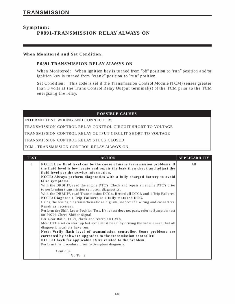
Symptom:P0891-TRANSMISSION RELAY ALWAYS ON
When Monitored and Set Condition:
P0891-TRANSMISSION RELAY ALWAYS ON
When Monitored: When ignition key is turned from 9off9 position to 9run9 position and/orignition key is turned from 9crank9 position to 9run9 position.
Set Condition: This code is set if the Transmission Control Module (TCM) senses greaterthan 3 volts at the Trans Control Relay Output terminal(s) of the TCM prior to the TCMenergizing the relay.
POSSIBLE CAUSES
INTERMITTENT WIRING AND CONNECTORS
TRANSMISSION CONTROL RELAY CONTROL CIRCUIT SHORT TO VOLTAGE
TRANSMISSION CONTROL RELAY OUTPUT CIRCUIT SHORT TO VOLTAGE
TRANSMISSION CONTROL RELAY STUCK CLOSED
TCM - TRANSMISSION CONTROL RELAY ALWAYS ON
TEST ACTION APPLICABILITY
1 NOTE: Low fluid level can be the cause of many transmission problems. Ifthe fluid level is low locate and repair the leak then check and adjust thefluid level per the service information.NOTE: Always perform diagnostics with a fully charged battery to avoidfalse symptoms.With the DRBIIIt, read the engine DTC’s. Check and repair all engine DTC’s priorto performing transmission symptom diagnostics.With the DRBIIIt, read Transmission DTC’s. Record all DTC’s and 1 Trip Failures.NOTE: Diagnose 1 Trip Failures as a fully matured DTC.Using the wiring diagram/schematic as a guide, inspect the wiring and connectors.Repair as necessary.Perform the Shift Lever Position Test. If the test does not pass, refer to Symptom testfor P0706 Check Shifter Signal.For Gear Ratio DTC’s, check and record all CVI’s.Most DTC’s set on start up but some must be set by driving the vehicle such that alldiagnostic monitors have run.Note: Verify flash level of transmission controller. Some problems arecorrected by software upgrades to the transmission controller.NOTE: Check for applicable TSB’s related to the problem.Perform this procedure prior to Symptom diagnosis.
All
ContinueGo To 2
148
TRANSMISSION

TEST ACTION APPLICABILITY
2 With the DRBIIIt, Check the STARTS SINCE SET counter.NOTE: This counter only applies to the last DTC set.Is the STARTS SINCE SET counter equal to 0?
5-SPD AUTO-MATIC 5-45RFE
TRANS
Yes → Go To 3
No → Go To 7
3 Turn the ignition off to the lock position.Disconnect the TCM harness connector.Remove the Transmission Control Relay from the PDC.Note: Check connectors - Clean/repair as necessary.Ignition on, engine not running.Measure the voltage at the Transmission Control Relay Control circuit in theTransmission Control Relay connector.Is the voltage above 0.5 volts?
5-SPD AUTO-MATIC 5-45RFE
TRANS
Yes → Repair the Transmission Control Relay Control circuit for a shortto voltage.Perform 45RFE/545RFE TRANSMISSION VERIFICATIONTEST - VER 1.
No → Go To 4
4 Turn the ignition off to the lock position.Remove the Transmission Control Relay from the PDC.Turn the ignition off to the lock position.Measure the voltage at the Transmission Control Relay Output circuit in theTransmission Control Relay connector.Is the voltage above 0.5 volts?
5-SPD AUTO-MATIC 5-45RFE
TRANS
Yes → Repair the Transmission Control Relay Output circuit for a shortto voltage.Perform 45RFE/545RFE TRANSMISSION VERIFICATIONTEST - VER 1.
No → Go To 5
5 Turn the ignition off to the lock position.Remove the Transmission Control Relay from the PDC.Note: Check connectors - Clean/repair as necessary.Measure the resistance between the Fused B(+) circuit and the Transmission ControlRelay Output Circuit, Pins 30 and 87, of the Transmission Control Relay.Is the resistance above 5.0 ohms?
5-SPD AUTO-MATIC 5-45RFE
TRANS
Yes → Go To 6
No → Replace the Transmission Control Relay.Perform 45RFE/545RFE TRANSMISSION VERIFICATIONTEST - VER 1.
6 If there are no possible causes remaining, view repair. 5-SPD AUTO-MATIC 5-45RFE
TRANS
RepairReplace the Transmission Control Module. WITH THE DRBIIItPERFORM QUICK LEARNPerform 45RFE/545RFE TRANSMISSION VERIFICATIONTEST - VER 1.
149
TRANSMISSION
P0891-TRANSMISSION RELAY ALWAYS ON — Continued

TEST ACTION APPLICABILITY
7 The conditions necessary to set this DTC are not present at this time.Using the schematics as a guide, inspect the wiring and connectors specific to thiscircuit.Wiggle the wires while checking for shorts and open circuits.Were there any problems found?
5-SPD AUTO-MATIC 5-45RFE
TRANS
Yes → Repair as necessary.Perform 45RFE/545RFE TRANSMISSION VERIFICATIONTEST - VER 1.
No → Test Complete.
150
TRANSMISSION
P0891-TRANSMISSION RELAY ALWAYS ON — Continued

Symptom:P0932-LINE PRESSURE SENSOR FAULT
When Monitored and Set Condition:
P0932-LINE PRESSURE SENSOR FAULT
When Monitored: Continuously with engine running.
Set Condition: If the Line Pressure Sensor (LPS) voltage is below 0.2 volts or above 4.75volts the code will be set.
POSSIBLE CAUSES
INTERMITTENT WIRING AND CONNECTORS
5-VOLT SUPPLY CIRCUIT OPEN
GROUND CIRCUIT OPEN
LINE PRESSURE SENSOR SIGNAL CIRCUIT OPEN
5-VOLT SUPPLY CIRCUIT SHORT TO GROUND
LINE PRESSURE SENSOR SIGNAL CIRCUIT SHORT TO GROUND
LINE PRESSURE SENSOR SIGNAL CIRCUIT SHORT TO VOLTAGE
LINE PRESSURE SENSOR
TCM - HIGH LINE PRESSURE SENSOR
TCM - LOW LINE PRESSURE SENSOR
TEST ACTION APPLICABILITY
1 NOTE: Low fluid level can be the cause of many transmission problems. Ifthe fluid level is low locate and repair the leak then check and adjust thefluid level per the service information.NOTE: Always perform diagnostics with a fully charged battery to avoidfalse symptoms.With the DRBIIIt, read the engine DTC’s. Check and repair all engine DTC’s priorto performing transmission symptom diagnostics.With the DRBIIIt, read Transmission DTC’s. Record all DTC’s and 1 Trip Failures.NOTE: Diagnose 1 Trip Failures as a fully matured DTC.Using the wiring diagram/schematic as a guide, inspect the wiring and connectors.Repair as necessary.Perform the Shift Lever Position Test. If the test does not pass, refer to Symptom testfor P0706 Check Shifter Signal.For Gear Ratio DTC’s, check and record all CVI’s.Most DTC’s set on start up but some must be set by driving the vehicle such that alldiagnostic monitors have run.Note: Verify flash level of transmission controller. Some problems arecorrected by software upgrades to the transmission controller.NOTE: Check for applicable TSB’s related to the problem.Perform this procedure prior to Symptom diagnosis.
All
ContinueGo To 2
151
TRANSMISSION

TEST ACTION APPLICABILITY
2 Ignition on, engine not running.With the DRBIIIt, read the Line Pressure Sensor voltage.Is the Line Pressure Sensor voltage between 0.2 and 4.75 volts?
5-SPD AUTO-MATIC 5-45RFE
TRANS
Yes → Go To 3
No → Go To 4
3 The conditions necessary to set this DTC are not present at this time. Using theschematics as a guide, inspect the wiring and connectors specific to this circuit.Wiggle the wires while checking for shorts and open circuits.Were any problems found?
5-SPD AUTO-MATIC 5-45RFE
TRANS
Yes → Repair as necessary.Perform 45RFE/545RFE TRANSMISSION VERIFICATIONTEST - VER 1.
No → Test Complete.
4 Turn the ignition off to the lock position.Remove the Starter Relay from the PDC.NOTE: Failure to remove the Starter Relay can cause a TCM - No Responsecondition.Install Transmission Simulator Miller tool #8333.Ignition on, engine not running.With the DRBIIIt, monitor the Line Pressure.Using the Transmission Simulator, set the rotary switch to each of the 3 line pressurepositions.Note: The readings should be within ± 2.0 PSI on the DRBIIIt of the pressure readingspecified on Transmission Simulator.What is the Line Pressure Sensor voltage?
5-SPD AUTO-MATIC 5-45RFE
TRANS
Below 0.2 volts (241Kpa or 35 PSI).Go To 5
Between .2 and 4.75 volts (76 PSI)Go To 9
Above 4.75 volts (1586 Kpa or 230 PSI)Go To 10
5 Turn ignition switch to the lock positionDisconnect the TCM harness connector.Disconnect the Line Pressure Sensor connector.Note: Check connectors - Clean/repair as necessary.Measure the resistance of the 5-Volt Supply circuit from the Line Pressure Sensorconnector to the TCM connector.Is the resistance above 5.0 ohms?
5-SPD AUTO-MATIC 5-45RFE
TRANS
Yes → Repair the 5-volt Supply circuit for an open.Perform 45RFE/545RFE TRANSMISSION VERIFICATIONTEST - VER 1.
No → Go To 6
152
TRANSMISSION
P0932-LINE PRESSURE SENSOR FAULT — Continued

TEST ACTION APPLICABILITY
6 Turn ignition switch to the lock position.Disconnect the TCM harness connector.Disconnect the Line Pressure Sensor harness connector.Note: Check connectors - Clean/repair as necessary.Measure the resistance between the 5-Volt Supply circuit and ground.Is the resistance Below 5.0 ohms?
5-SPD AUTO-MATIC 5-45RFE
TRANS
Yes → Repair the 5-volt Supply circuit for a short to ground.Perform 45RFE/545RFE TRANSMISSION VERIFICATIONTEST - VER 1.
No → Go To 7
7 Turn ignition switch to the lock position.Disconnect the TCM harness connector.Disconnect the Line Pressure Sensor connector.Note: Check connectors - Clean/repair as necessary.Measure the resistance between the Line Pressure Sensor Signal circuit and ground.Is the resistance Below 5.0 ohms?
5-SPD AUTO-MATIC 5-45RFE
TRANS
Yes → Repair the Line Pressure Sensor Signal circuit for a short toground.Perform 45RFE/545RFE TRANSMISSION VERIFICATIONTEST - VER 1.
No → Go To 8
8 If there are no possible causes remaining, view repair. 5-SPD AUTO-MATIC 5-45RFE
TRANS
RepairReplace the Transmission Control Module. WITH THE DRBIIItPERFORM QUICK LEARNPerform 45RFE/545RFE TRANSMISSION VERIFICATIONTEST - VER 1.
9 If there are no possible causes remaining, view repair. 5-SPD AUTO-MATIC 5-45RFE
TRANS
RepairReplace the Line Pressure Sensor.Perform 45RFE/545RFE TRANSMISSION VERIFICATIONTEST - VER 1.
10 Turn ignition switch to the lock positionDisconnect the TCM harness connector.Disconnect the Line Pressure Sensor connector.Note: Check connectors - Clean/repair as necessary.Measure the resistance of the Ground circuit from the Line Pressure Sensorconnector to the TCM connector.Is the resistance above 5.0 ohms?
5-SPD AUTO-MATIC 5-45RFE
TRANS
Yes → Repair the Ground circuit for an open.Perform 45RFE/545RFE TRANSMISSION VERIFICATIONTEST - VER 1.
No → Go To 11
153
TRANSMISSION
P0932-LINE PRESSURE SENSOR FAULT — Continued

TEST ACTION APPLICABILITY
11 Turn ignition switch to the lock positionDisconnect the TCM harness connector..Disconnect the Line Pressure Sensor connector.Note: Check connectors - Clean/repair as necessary.Measure the resistance of the Line Pressure Sensor Signal circuit from the LinePressure Sensor connector to the TCM connector.Is the resistance above 5.0 ohms?
5-SPD AUTO-MATIC 5-45RFE
TRANS
Yes → Repair the Line Pressure Sensor Signal circuit for an open.Perform 45RFE/545RFE TRANSMISSION VERIFICATIONTEST - VER 1.
No → Go To 12
12 Turn the ignition switch to the lock position.Disconnect the TCM harness connector.Remove the Transmission Control Relay.Note: Check connectors - Clean/repair as necessary.Connect a jumper wire between the Fused B(+) and the Transmission Relay Outputcircuits in the relay connector.Turn ignition on.Measure the voltage of the Line Pressure Sensor Signal circuit in the TCM connector.Is the voltage above 5.5 volts?
5-SPD AUTO-MATIC 5-45RFE
TRANS
Yes → Repair the Line Pressure Sensor Signal circuit for a short tovoltage.Perform 45RFE/545RFE TRANSMISSION VERIFICATIONTEST - VER 1.
No → Go To 13
13 If there are no possible causes remaining, view repair. 5-SPD AUTO-MATIC 5-45RFE
TRANS
RepairReplace the Transmission Control Module. WITH THE DRBIIItPERFORM QUICK LEARNPerform 45RFE/545RFE TRANSMISSION VERIFICATIONTEST - VER 1.
154
TRANSMISSION
P0932-LINE PRESSURE SENSOR FAULT — Continued

Symptom:P0944-LOSS OF PRIME
When Monitored and Set Condition:
P0944-LOSS OF PRIME
When Monitored: If the transmission is slipping in any forward gear and the pressureswitches are not indicating pressure, a loss of prime test is run.
Set Condition: If the transmission begins to slip in a forward gear and the pressureswitch(s) that should be closed are open a loss of prime test begins. Available elements areturned on by the TCM to see if pump prime exists. The DTC sets if no pressure switch(s)respond.
POSSIBLE CAUSES
INVALID PRNDL CODE
INTERMITTENT OPERATION
TRANSMISSION OIL FILTER
OIL PUMP - LOSS OF PRIME
TEST ACTION APPLICABILITY
1 NOTE: Low fluid level can be the cause of many transmission problems. Ifthe fluid level is low locate and repair the leak then check and adjust thefluid level per the service information.NOTE: Always perform diagnostics with a fully charged battery to avoidfalse symptoms.With the DRBIIIt, read the engine DTC’s. Check and repair all engine DTC’s priorto performing transmission symptom diagnostics.With the DRBIIIt, read Transmission DTC’s. Record all DTC’s and 1 Trip Failures.NOTE: Diagnose 1 Trip Failures as a fully matured DTC.Using the wiring diagram/schematic as a guide, inspect the wiring and connectors.Repair as necessary.Perform the Shift Lever Position Test. If the test does not pass, refer to Symptom testfor P0706 Check Shifter Signal.For Gear Ratio DTC’s, check and record all CVI’s.Most DTC’s set on start up but some must be set by driving the vehicle such that alldiagnostic monitors have run.Note: Verify flash level of transmission controller. Some problems arecorrected by software upgrades to the transmission controller.NOTE: Check for applicable TSB’s related to the problem.Perform this procedure prior to Symptom diagnosis.
All
ContinueGo To 2
155
TRANSMISSION

TEST ACTION APPLICABILITY
2 Start the engine.The transmission must be at operating temperature prior to checking pressure. Acold transmission will give higher readings.Firmly apply the brakes and place transmission in (R) reverse.With the DRBIIIt, monitor the Transmission Line Pressure.Is the Line Pressure below 1034 kpa (150 PSI) or is it fluctuating more than +/- 69kpa (10 PSI).
5-SPD AUTO-MATIC 5-45RFE
TRANS
No → Go To 3
Yes → Go To 4
3 The conditions necessary to set this DTC are not present at this time.Verify with the customer if a delayed engagement and/or an intermittent 9No Drive9condition has occurred.If the customers answer is 9No9 erase the DTC and return the vehicle to the customer.Make sure to check for any TSBs or controller flash updates that my apply.Has the customer experienced any delayed engagement and/or 9No Drive9 conditions?
5-SPD AUTO-MATIC 5-45RFE
TRANS
Yes → Repair internal transmission problem as necessary. Replace theTransmission Oil Pump if inspection reveals no signs of internalseal leakage. Refer to the Service Information for the properrepair procedure.Perform 45RFE/545RFE TRANSMISSION VERIFICATIONTEST - VER 1.
No → Test Complete.
4 Using the DRBIIIt, perform a Shift Lever Position test. Follow the instructions onthe DRBIIIt.Did the Shift Lever Position Test pass?
5-SPD AUTO-MATIC 5-45RFE
TRANS
Yes → Go To 5
No → Refer to symptom list and perform the appropriate test for DTCP0706.Perform 45RFE/545RFE TRANSMISSION VERIFICATIONTEST - VER 1.
5 Remove and inspect the Transmission Oil Pan per the Service Information.Remove and inspect the Primary Oil Filter per the Service Information.Inspect the oil filter O-ring for damage and proper installation.Does the Oil Pan contain excessive debris and/or is the Oil Filter plugged or O-ringdamaged?
5-SPD AUTO-MATIC 5-45RFE
TRANS
Yes → Repair the cause of the plugged transmission oil filter or excessivedebris, Seal installed onto filter neck instead of into pump bore,seal not fully seated against pump housing, filter neck notengaged into pump. See Service information.Perform 45RFE/545RFE TRANSMISSION VERIFICATIONTEST - VER 1.
No → Go To 6
156
TRANSMISSION
P0944-LOSS OF PRIME — Continued

TEST ACTION APPLICABILITY
6 If there are no possible causes remaining, view repair. 5-SPD AUTO-MATIC 5-45RFE
TRANS
RepairReplace the Transmission or Transmission Oil Pump as necessary.Refer to the Service Information for the proper repair procedure.Perform 45RFE/545RFE TRANSMISSION VERIFICATIONTEST - VER 1.
157
TRANSMISSION
P0944-LOSS OF PRIME — Continued

Symptom:P0987-4C HYDRAULIC PRESSURE TEST FAILURE
When Monitored and Set Condition:
P0987-4C HYDRAULIC PRESSURE TEST FAILURE
When Monitored: In any forward gear with engine speed above 1000 RPM shortly aftera shift and every minute thereafter.
Set Condition: After a shift into a forward gear, with engine speed > 1000 RPM, the TCMmomentarily turns on element pressure to the clutch circuits that don’t have pressure toidentify the correct pressure switch closes. If the pressure switch does not close 2 times theDTC sets
POSSIBLE CAUSES
RELATED LINE PRESSURE DTC’S PRESENT
RELATED SPEED RATIO AND/OR PRESSURE SWITCH DTC PRESENT
POOR LINE PRESSURE SENSOR CONNECTION
TCM AND WIRING - LOW LINE PRESSURE
INTERMITTENT WIRING AND CONNECTORS
4C PRESSURE SWITCH SENSE CIRCUIT OPEN
5-VOLT SUPPLY CIRCUIT OPEN
TRANSMISSION CONTROL RELAY OUTPUT CIRCUIT OPEN
4C PRESSURE SWITCH SENSE CIRCUIT SHORT TO GROUND
5-VOLT SUPPLY CIRCUIT SHORT TO GROUND
4C PRESSURE SWITCH SENSE CIRCUIT SHORT TO VOLTAGE
EXCESSIVE DEBRIS IN OIL PAN
INTERNAL TRANSMISSION - 4C PRESSURE TEST
TCM - 4C PRESSURE SWITCH
TCM - NO 5 VOLTS LOW LINE PRESSURE SENSOR
158
TRANSMISSION

TEST ACTION APPLICABILITY
1 NOTE: Low fluid level can be the cause of many transmission problems. Ifthe fluid level is low locate and repair the leak then check and adjust thefluid level per the service information.NOTE: Always perform diagnostics with a fully charged battery to avoidfalse symptoms.With the DRBIIIt, read the engine DTC’s. Check and repair all engine DTC’s priorto performing transmission symptom diagnostics.With the DRBIIIt, read Transmission DTC’s. Record all DTC’s and 1 Trip Failures.NOTE: Diagnose 1 Trip Failures as a fully matured DTC.Using the wiring diagram/schematic as a guide, inspect the wiring and connectors.Repair as necessary.Perform the Shift Lever Position Test. If the test does not pass, refer to Symptom testfor P0706 Check Shifter Signal.For Gear Ratio DTC’s, check and record all CVI’s.Most DTC’s set on start up but some must be set by driving the vehicle such that alldiagnostic monitors have run.Note: Verify flash level of transmission controller. Some problems arecorrected by software upgrades to the transmission controller.NOTE: Check for applicable TSB’s related to the problem.Perform this procedure prior to Symptom diagnosis.
All
ContinueGo To 2
2 With the DRBIIIt, check for other transmission DTC’sAre there any Line Pressure related DTC’s P0867, P0932, P0868, P0869, or P0944present?
5-SPD AUTO-MATIC 5-45RFE
TRANS
Yes → Refer to symptom list and perform the appropriate test.Perform 45RFE/545RFE TRANSMISSION VERIFICATIONTEST - VER 1.
No → Go To 3
3 With the DRBIIIt, check for other transmission DTC’sIs the DTC P0734 and/or P0988 present also?
5-SPD AUTO-MATIC 5-45RFE
TRANS
Yes → Replace the Transmission Solenoid/TRS Assembly per the ServiceInformation.Perform 45RFE/545RFE TRANSMISSION VERIFICATIONTEST - VER 1.
No → Go To 4
4 Perform a visual inspection of all connectors, wiring, and cooler connections beforeproceeding. Repair as necessary.With the DRBIIIt, Check the STARTS SINCE SET counter for P0987.NOTE: This counter only applies to the last DTC set.Is the STARTS SINCE SET counter 2 or less?
5-SPD AUTO-MATIC 5-45RFE
TRANS
Yes → Go To 5
No → Go To 19
159
TRANSMISSION
P0987-4C HYDRAULIC PRESSURE TEST FAILURE — Continued
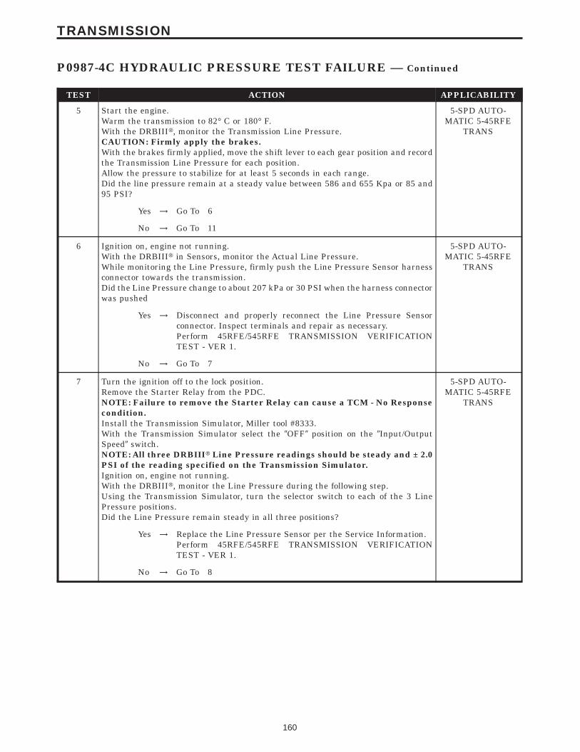
TEST ACTION APPLICABILITY
5 Start the engine.Warm the transmission to 82° C or 180° F.With the DRBIIIt, monitor the Transmission Line Pressure.CAUTION: Firmly apply the brakes.With the brakes firmly applied, move the shift lever to each gear position and recordthe Transmission Line Pressure for each position.Allow the pressure to stabilize for at least 5 seconds in each range.Did the line pressure remain at a steady value between 586 and 655 Kpa or 85 and95 PSI?
5-SPD AUTO-MATIC 5-45RFE
TRANS
Yes → Go To 6
No → Go To 11
6 Ignition on, engine not running.With the DRBIIIt in Sensors, monitor the Actual Line Pressure.While monitoring the Line Pressure, firmly push the Line Pressure Sensor harnessconnector towards the transmission.Did the Line Pressure change to about 207 kPa or 30 PSI when the harness connectorwas pushed
5-SPD AUTO-MATIC 5-45RFE
TRANS
Yes → Disconnect and properly reconnect the Line Pressure Sensorconnector. Inspect terminals and repair as necessary.Perform 45RFE/545RFE TRANSMISSION VERIFICATIONTEST - VER 1.
No → Go To 7
7 Turn the ignition off to the lock position.Remove the Starter Relay from the PDC.NOTE: Failure to remove the Starter Relay can cause a TCM - No Responsecondition.Install the Transmission Simulator, Miller tool #8333.With the Transmission Simulator select the 9OFF9 position on the 9Input/OutputSpeed9 switch.NOTE: All three DRBIIIt Line Pressure readings should be steady and ± 2.0PSI of the reading specified on the Transmission Simulator.Ignition on, engine not running.With the DRBIIIt, monitor the Line Pressure during the following step.Using the Transmission Simulator, turn the selector switch to each of the 3 LinePressure positions.Did the Line Pressure remain steady in all three positions?
5-SPD AUTO-MATIC 5-45RFE
TRANS
Yes → Replace the Line Pressure Sensor per the Service Information.Perform 45RFE/545RFE TRANSMISSION VERIFICATIONTEST - VER 1.
No → Go To 8
160
TRANSMISSION
P0987-4C HYDRAULIC PRESSURE TEST FAILURE — Continued

TEST ACTION APPLICABILITY
8 Turn the ignition off to the lock position.Disconnect the TCM harness connector.Disconnect the Line Pressure Sensor harness connector.Note: Check connectors - Clean/repair as necessary.Measure the resistance of the 5-volt Supply circuit from the Line Pressure Sensorharness connector to the TCM harness connector.Is the resistance above 5.0 ohms?
5-SPD AUTO-MATIC 5-45RFE
TRANS
Yes → Repair the 5-volt Supply circuit for an open.Perform 45RFE/545RFE TRANSMISSION VERIFICATIONTEST - VER 1.
No → Go To 9
9 Turn the ignition off to the lock position.Disconnect the TCM harness connector.Disconnect the Line Pressure Sensor harness connector.Note: Check connectors - Clean/repair as necessary.Measure the resistance between ground and the 5-volt Supply circuit.Is the resistance below 5.0 ohms?
5-SPD AUTO-MATIC 5-45RFE
TRANS
Yes → Repair 5-volt supply circuit for a short to ground.Perform 45RFE/545RFE TRANSMISSION VERIFICATIONTEST - VER 1.
No → Go To 10
10 If there are no possible causes remaining, view repair. 5-SPD AUTO-MATIC 5-45RFE
TRANS
RepairReplace the Transmission Control Module. WITH THE DRBIIItPERFORM QUICK LEARNPerform 45RFE/545RFE TRANSMISSION VERIFICATIONTEST - VER 1.
11 Turn the ignition off to the lock position.Remove the Starter Relay from the PDC.NOTE: Failure to remove the Starter Relay can cause a TCM - No Responsecondition.Install the Transmission Simulator, Miller tool #8333.Note: Check connectors - Clean/repair as necessary.Ignition on, engine not running.On the Transmission Simulator, place the Pressure Switch selector switch to 4C.With the DRBIIIt, monitor the 4C Pressure Switch state.While monitoring the DRBIIIt press the Pressure Switch Test button on theTransmission Simulator while wiggling the wiring pertaining to the 4C PressureSwitch.Did the 4C Pressure Switch state change to closed and remain closed while wigglingthe wires?
5-SPD AUTO-MATIC 5-45RFE
TRANS
Yes → Go To 12
No → Go To 14
161
TRANSMISSION
P0987-4C HYDRAULIC PRESSURE TEST FAILURE — Continued

TEST ACTION APPLICABILITY
12 Remove and inspect Transmission Oil Pan per Service Information.Does the Transmission Oil Pan contain excessive debris or contamination?
5-SPD AUTO-MATIC 5-45RFE
TRANS
Yes → Repair the cause of the excessive debris in the Transmission OilPan. Refer to the Service Information for the proper procedures.Perform 45RFE/545RFE TRANSMISSION VERIFICATIONTEST - VER 1.
No → Go To 13
13 If there are no possible causes remaining, view repair. 5-SPD AUTO-MATIC 5-45RFE
TRANS
RepairRepair Internal Transmission as necessary. Disassemble andinspect the Valve Body and repair or replace as necessary. If noproblems are found in the Valve Body, replace the TransmissionSolenoid/TRS Assembly.Perform 45RFE/545RFE TRANSMISSION VERIFICATIONTEST - VER 1.
14 Turn the ignition off to the lock position.Disconnect the TCM harness connector.Disconnect the Transmission Solenoid /TRS harness connectorNote: Check connectors - Clean/repair as necessary.Measure the resistance of the 4C Pressure Switch Sense circuit between the TCMharness connector to the Solenoid/TRS harness connector.Is the resistance above 5.0 ohms?
5-SPD AUTO-MATIC 5-45RFE
TRANS
Yes → Repair the 4C Pressure Switch Sense circuit for an open.Perform 45RFE/545RFE TRANSMISSION VERIFICATIONTEST - VER 1.
No → Go To 15
15 Turn the ignition off to the lock position.Disconnect the TCM harness connector.Disconnect the Transmission Solenoid/TRS harness connector.Remove the Transmission Control Relay from the PDC.NOTE: Failure to remove the Starter Relay can cause a TCM - No Responsecondition.Connect a jumper wire between the Fused B(+) circuit and the Transmission ControlRelay Output circuit in the Transmission Control Relay connector.Ignition on, engine not running.Using a 12-volt test light connected to ground, check the Transmission Control RelayOutput circuit in the TCM harness connector.NOTE: The test light must illuminate brightly. Compare the brightness tothat of a direct connection to the battery.Does the test light illuminate brightly?
5-SPD AUTO-MATIC 5-45RFE
TRANS
Yes → Go To 16
No → Repair the Transmission Control Relay Output circuit for anopen. If the fuse is open make sure to check for a short to ground.Perform 45RFE/545RFE TRANSMISSION VERIFICATIONTEST - VER 1.
162
TRANSMISSION
P0987-4C HYDRAULIC PRESSURE TEST FAILURE — Continued

TEST ACTION APPLICABILITY
16 Turn the ignition off to the lock position.Disconnect the TCM harness connector.Disconnect the Transmission Solenoid/TRS harness connector.Note: Check connectors - Clean/repair as necessary.Measure the resistance between ground and the 4C Pressure Switch Sense circuit.Is the resistance below 5.0 ohms?
5-SPD AUTO-MATIC 5-45RFE
TRANS
Yes → Repair the 4C Pressure Switch Sense circuit for a short to ground.Perform 45RFE/545RFE TRANSMISSION VERIFICATIONTEST - VER 1.
No → Go To 17
17 Turn the ignition off to the lock position.Disconnect the Transmission Control Module harness connector.Disconnect the Transmission Solenoid/TRS harness connector.Remove the Transmission Control Relay from the PDC.Note: Check connectors - Clean/repair as necessary.Connect a jumper wire between the Fused B(+) circuit and the Transmission ControlRelay Output circuit in the Transmission Control Relay connector.Ignition on, engine not running.Measure the voltage of the 4C Pressure Switch Sense circuit in the TCM harnessconnector.Is the voltage above 0.5 volt?
5-SPD AUTO-MATIC 5-45RFE
TRANS
Yes → Repair the 4C Pressure Switch Sense circuit for a short to voltage.Perform 45RFE/545RFE TRANSMISSION VERIFICATIONTEST - VER 1.
No → Go To 18
18 If there are no possible causes remaining, view repair. 5-SPD AUTO-MATIC 5-45RFE
TRANS
RepairReplace the Transmission Control Module. WITH THE DRBIIItPERFORM QUICK LEARN.Perform 45RFE/545RFE TRANSMISSION VERIFICATIONTEST - VER 1.
19 The conditions necessary to set this DTC are not present at this time.Using the schematics as a guide, inspect the wiring and connectors specific to thiscircuit.Wiggle the wires while checking for shorts and open circuits.Were there any problems found?
5-SPD AUTO-MATIC 5-45RFE
TRANS
Yes → Repair as necessary.Perform 45RFE/545RFE TRANSMISSION VERIFICATIONTEST - VER 1.
No → Test Complete.
163
TRANSMISSION
P0987-4C HYDRAULIC PRESSURE TEST FAILURE — Continued

Symptom:P0988-4C PRESSURE SWITCH SENSE CIRCUIT
When Monitored and Set Condition:
P0988-4C PRESSURE SWITCH SENSE CIRCUIT
When Monitored: Whenever the engine is running.
Set Condition: This DTC is set if the 4C pressure switch is in the wrong state for thecurrent gear. For example, this code would be set if the 4C pressure switch came on whilethe transmission was in second gear.
POSSIBLE CAUSES
RELATED RELAY DTC’S PRESENT
INTERMITTENT CONDITIONS
4C PRESSURE SWITCH SENSE CIRCUIT OPEN
TRANSMISSION CONTROL RELAY OUTPUT CIRCUIT OPEN
4C PRESSURE SWITCH SENSE CIRCUIT SHORT TO GROUND
4C PRESSURE SWITCH SENSE CIRCUIT SHORT TO VOLTAGE
4C PRESSURE SWITCH
TCM - 4C PRESSURE SWITCH
TEST ACTION APPLICABILITY
1 NOTE: Low fluid level can be the cause of many transmission problems. Ifthe fluid level is low locate and repair the leak then check and adjust thefluid level per the service information.NOTE: Always perform diagnostics with a fully charged battery to avoidfalse symptoms.With the DRBIIIt, read the engine DTC’s. Check and repair all engine DTC’s priorto performing transmission symptom diagnostics.With the DRBIIIt, read Transmission DTC’s. Record all DTC’s and 1 Trip Failures.NOTE: Diagnose 1 Trip Failures as a fully matured DTC.Using the wiring diagram/schematic as a guide, inspect the wiring and connectors.Repair as necessary.Perform the Shift Lever Position Test. If the test does not pass, refer to Symptom testfor P0706 Check Shifter Signal.For Gear Ratio DTC’s, check and record all CVI’s.Most DTC’s set on start up but some must be set by driving the vehicle such that alldiagnostic monitors have run.Note: Verify flash level of transmission controller. Some problems arecorrected by software upgrades to the transmission controller.NOTE: Check for applicable TSB’s related to the problem.Perform this procedure prior to Symptom diagnosis.
All
ContinueGo To 2
164
TRANSMISSION

TEST ACTION APPLICABILITY
2 With the DRBIIIt, check for other transmission DTC’s.Are there any Transmission Control Relay related DTC’s P0890, P0891, or P0888present?
5-SPD AUTO-MATIC 5-45RFE
TRANS
Yes → Refer to symptom list and perform test for Transmission ControlRelay related DTCs.Perform 45RFE/545RFE TRANSMISSION VERIFICATIONTEST - VER 1.
No → Go To 3
3 Ignition on, engine not running.With the DRBIIIt, Check the STARTS SINCE SET counter.NOTE: This counter only applies to the last DTC set.Is the STARTS SINCE SET counter for P0988, 2 or less?
5-SPD AUTO-MATIC 5-45RFE
TRANS
Yes → Go To 4
No → Go To 11
4 Turn the ignition off to the lock position.Remove the Starter Relay from the PDC.NOTE: Failure to remove the Starter Relay can cause a TCM - No Responsecondition.Install the Transmission Simulator, Miller tool #8333.Note: Check connectors - Clean/repair as necessary.Ignition on, engine not running.With the Transmission Simulator turn the Pressure Switch selector switch to 4C.With the DRBIIIt, monitor the 4C Pressure Switch state while pressing the PressureSwitch Test button.Did the state of the 4C Pressure Switch change while pressing the Pressure SwitchTest button?
5-SPD AUTO-MATIC 5-45RFE
TRANS
Yes → Go To 5
No → Go To 6
5 If there are no possible causes remaining, view repair. 5-SPD AUTO-MATIC 5-45RFE
TRANS
RepairReplace the Transmission Solenoid/TRS Assembly per the ServiceInformation.Perform 45RFE/545RFE TRANSMISSION VERIFICATIONTEST - VER 1.
6 Turn the ignition off to the lock position.Disconnect the TCM harness connector.Disconnect the Transmission Solenoid /TRS Assembly harness connectorNote: Check connectors - Clean/repair as necessary.Measure the resistance of the 4C Pressure Switch Sense circuit from the TCMharness connector to the Transmission Solenoid/TRS Assembly harness connector.Is the resistance above 5.0 ohms?
5-SPD AUTO-MATIC 5-45RFE
TRANS
Yes → Repair the 4C Pressure Switch Sense circuit for an open.Perform 45RFE/545RFE TRANSMISSION VERIFICATIONTEST - VER 1.
No → Go To 7
165
TRANSMISSION
P0988-4C PRESSURE SWITCH SENSE CIRCUIT — Continued

TEST ACTION APPLICABILITY
7 Turn the ignition off to the lock position.Disconnect the Transmission Solenoid/TRS Assembly harness connector.Ignition on, engine not running.Using a 12-volt test light connected to ground, check the Transmission Control RelayOutput circuit in the Transmission Solenoid/TRS Assembly harness connector.NOTE: The test light must illuminate brightly. Compare the brightness tothat of a direct connection to the battery.Does the test light illuminate brightly?
5-SPD AUTO-MATIC 5-45RFE
TRANS
Yes → Go To 8
No → Repair the Transmission Control Relay Output circuit for anopen. If the fuse is open make sure to check for a short to ground.Perform 45RFE/545RFE TRANSMISSION VERIFICATIONTEST - VER 1.
8 Turn the ignition off to the lock position.Disconnect the TCM harness connector.Disconnect the Transmission Solenoid/TRS Assembly harness connector.Note: Check connectors - Clean/repair as necessary.Measure the resistance between ground and the 4C Pressure Switch Sense circuit.Is the resistance below 5.0 ohms?
5-SPD AUTO-MATIC 5-45RFE
TRANS
Yes → Repair the 4C Pressure Switch Sense circuit for a short to ground.Perform 45RFE/545RFE TRANSMISSION VERIFICATIONTEST - VER 1.
No → Go To 9
9 Turn the ignition off to the lock position.Disconnect the Transmission Control Module harness connector.Disconnect the Transmission Solenoid/TRS Assembly harness connector.Remove the Transmission Control Relay from the PDC.Note: Check connectors - Clean/repair as necessary.Connect a jumper wire between the Fused B+ circuit and the Transmission ControlRelay Output circuit in the Transmission Control Relay connector.Ignition on, engine not running.Measure the voltage of the 4C Pressure Switch Sense circuit in the TCM harnessconnector.Is the voltage above 0.5 volt?
5-SPD AUTO-MATIC 5-45RFE
TRANS
Yes → Repair the 4C Pressure Switch Sense circuit for a short to voltage.Perform 45RFE/545RFE TRANSMISSION VERIFICATIONTEST - VER 1.
No → Go To 10
10 If there are no possible causes remaining, view repair. 5-SPD AUTO-MATIC 5-45RFE
TRANS
RepairReplace the Transmission Control Module. WITH THE DRBIIItPERFORM QUICK LEARNPerform 45RFE/545RFE TRANSMISSION VERIFICATIONTEST - VER 1.
166
TRANSMISSION
P0988-4C PRESSURE SWITCH SENSE CIRCUIT — Continued

TEST ACTION APPLICABILITY
11 The conditions necessary to set this DTC are not present at this time.Using the schematics as a guide, inspect the wiring and connectors specific to thiscircuit.Wiggle the wires while checking for shorts and open circuits.Sump filter installed incorrectly.Reverse carrier snap ring dislodged (typically sets code on heavy throttle accelerationfrom a dead stop)Were there any problems found?
5-SPD AUTO-MATIC 5-45RFE
TRANS
Yes → Repair as necessary.Perform 45RFE/545RFE TRANSMISSION VERIFICATIONTEST - VER 1.
No → Test Complete.
167
TRANSMISSION
P0988-4C PRESSURE SWITCH SENSE CIRCUIT — Continued

Symptom:P1684-BATTERY WAS DISCONNECTED
When Monitored and Set Condition:
P1684-BATTERY WAS DISCONNECTED
When Monitored: Whenever the key is in the Run/Start position.
Set Condition: This code is set whenever Transmission Control Module - TCM isdisconnected from battery power B+ or ground. It will also be set during the DRBIIItBattery Disconnect procedure.
POSSIBLE CAUSES
BATTERY WAS DISCONNECTED
DRBIIIt BATTERY DISCONNECT PERFORMED
QUICK LEARN WAS PERFORMED
TCM WAS REPLACED OR DISCONNECTED
INTERMITTENT WIRING AND CONNECTORS
TEST ACTION APPLICABILITY
1 NOTE: Low fluid level can be the cause of many transmission problems. Ifthe fluid level is low locate and repair the leak then check and adjust thefluid level per the service information.NOTE: Always perform diagnostics with a fully charged battery to avoidfalse symptoms.With the DRBIIIt, read the engine DTC’s. Check and repair all engine DTC’s priorto performing transmission symptom diagnostics.With the DRBIIIt, read Transmission DTC’s. Record all DTC’s and 1 Trip Failures.NOTE: Diagnose 1 Trip Failures as a fully matured DTC.Using the wiring diagram/schematic as a guide, inspect the wiring and connectors.Repair as necessary.Perform the Shift Lever Position Test. If the test does not pass, refer to Symptom testfor P0706 Check Shifter Signal.For Gear Ratio DTC’s, check and record all CVI’s.Most DTC’s set on start up but some must be set by driving the vehicle such that alldiagnostic monitors have run.Note: Verify flash level of transmission controller. Some problems arecorrected by software upgrades to the transmission controller.NOTE: Check for applicable TSB’s related to the problem.Perform this procedure prior to Symptom diagnosis.
All
ContinueGo To 2
2 This DTC is an informational DTC only.This DTC is set due to a momentary loss of the Fused B(+) feed to the TCM.Continue to view the possible causes for this DTC.
5-SPD AUTO-MATIC 5-45RFE
TRANS
ContinueGo To 3
168
TRANSMISSION

TEST ACTION APPLICABILITY
3 Has the battery been disconnected, lost it’s charge, or been replaced recently? 5-SPD AUTO-MATIC 5-45RFE
TRANS
Yes → This is the cause of the DTC. Erase the DTC and return vehicle tocustomer.Perform 45RFE/545RFE TRANSMISSION VERIFICATIONTEST - VER 1.
No → Go To 4
4 Has a DRBIIIt Battery Disconnect procedure been performed? 5-SPD AUTO-MATIC 5-45RFE
TRANS
Yes → This is the cause of the DTC. Erase the DTC and return thevehicle to customer.Perform 45RFE/545RFE TRANSMISSION VERIFICATIONTEST - VER 1.
No → Go To 5
5 Has a 9QUICK LEARN9 been performed with the DRBIIIt? 5-SPD AUTO-MATIC 5-45RFE
TRANS
Yes → This is the cause of the DTC. Erase the DTC and return thevehicle to customer.Perform 45RFE/545RFE TRANSMISSION VERIFICATIONTEST - VER 1.
No → Go To 6
6 Has the TCM been replaced or disconnected? 5-SPD AUTO-MATIC 5-45RFE
TRANS
Yes → Replacing or disconnecting the TCM will set this DTC. Erase theDTC and return the vehicle to the customer.Perform 45RFE/545RFE TRANSMISSION VERIFICATIONTEST - VER 1.
No → Go To 7
7 The conditions necessary to set this DTC are not present at this time.Using the schematics as a guide, inspect the wiring and connectors specific to thiscircuit.NOTE: Check all power and ground circuits to the TCM for intermittent orhigh resistance circuits.Wiggle the wires while checking for shorts and open circuits.Check for any TSB’s or controller flash updates that may apply.Were there any problems found?
5-SPD AUTO-MATIC 5-45RFE
TRANS
Yes → Repair as necessary.Perform 45RFE/545RFE TRANSMISSION VERIFICATIONTEST - VER 1.
No → Test Complete.
169
TRANSMISSION
P1684-BATTERY WAS DISCONNECTED — Continued

Symptom:P1694-BUS COMMUNICATION WITH ENGINE MODULE
When Monitored and Set Condition:
P1694-BUS COMMUNICATION WITH ENGINE MODULE
When Monitored: Continuously with ignition key on.
Set Condition: If no bus messages are received from the Powertrain Control Module(PCM) for 10 seconds. Note: Some after market equipment will also set this DTC. example:remote starters and communication equipment.
POSSIBLE CAUSES
OTHER BUS PROBLEMS PRESENT
INTERMITTENT WIRING AND CONNECTORS
PCI BUS CIRCUIT OPEN
TCM - BUS PROBLEM
TEST ACTION APPLICABILITY
1 NOTE: Low fluid level can be the cause of many transmission problems. Ifthe fluid level is low locate and repair the leak then check and adjust thefluid level per the service information.NOTE: Always perform diagnostics with a fully charged battery to avoidfalse symptoms.With the DRBIIIt, read the engine DTC’s. Check and repair all engine DTC’s priorto performing transmission symptom diagnostics.With the DRBIIIt, read Transmission DTC’s. Record all DTC’s and 1 Trip Failures.NOTE: Diagnose 1 Trip Failures as a fully matured DTC.Using the wiring diagram/schematic as a guide, inspect the wiring and connectors.Repair as necessary.Perform the Shift Lever Position Test. If the test does not pass, refer to Symptom testfor P0706 Check Shifter Signal.For Gear Ratio DTC’s, check and record all CVI’s.Most DTC’s set on start up but some must be set by driving the vehicle such that alldiagnostic monitors have run.Note: Verify flash level of transmission controller. Some problems arecorrected by software upgrades to the transmission controller.NOTE: Check for applicable TSB’s related to the problem.Perform this procedure prior to Symptom diagnosis.
All
ContinueGo To 2
2 With the DRBIIIt, Check the STARTS SINCE SET counter.NOTE: This counter only applies to the last DTC set.Is the STARTS SINCE SET counter equal to zero?
5-SPD AUTO-MATIC 5-45RFE
TRANS
Yes → Go To 3
No → Go To 6
170
TRANSMISSION

TEST ACTION APPLICABILITY
3 With the DRBIIIt, attempt to communicate with other modules on the vehicle, checkfor evidence of a vehicle bus problem.Bus related DTC’s in other modules point to an overall vehicle bus problem. Othersymptoms such as a customer complaint of intermittent operation of bus controlledfeatures also indicate a bus problem.Does the PRNDL display indicate 9No Bus9 or is there any evidence of an overallvehicle bus problem?
5-SPD AUTO-MATIC 5-45RFE
TRANS
Yes → Refer to the Communication Category and perform the appropri-ate symptom.Perform 45RFE/545RFE TRANSMISSION VERIFICATIONTEST - VER 1.
No → Go To 4
4 Turn the ignition off to the lock position.Disconnect the PCM harness connectors.Note: Check connectors - Clean/repair as necessary.Measure the resistance of the PCI Bus circuit from the PCM harness connector to theData Link Connector.NOTE: CAREFULLY PROBE THE DLC. DAMAGE TO THE DLC TERMI-NALS WILL RESULT IN POOR TERMINAL TO PIN CONNECTION.Is the resistance above 5.0 ohms?
5-SPD AUTO-MATIC 5-45RFE
TRANS
Yes → Repair the open PCI Bus circuit between the PCM and the DataLink Connector.Perform 45RFE/545RFE TRANSMISSION VERIFICATIONTEST - VER 1.
No → Go To 5
5 If there are no possible causes remaining, view repair. 5-SPD AUTO-MATIC 5-45RFE
TRANS
RepairReplace the Transmission Control Module. WITH THE DRBIIItPERFORM QUICK LEARN.Perform 45RFE/545RFE TRANSMISSION VERIFICATIONTEST - VER 1.
6 The conditions necessary to set this DTC are not present at this time. Using theschematics as a guide, inspect the wiring and connectors specific to this circuit.Wiggle the wires while checking for shorts and open circuits.Were there any problems found?
5-SPD AUTO-MATIC 5-45RFE
TRANS
Yes → Repair as necessary. Note: Some after market equipment will setthis DTC.Perform 45RFE/545RFE TRANSMISSION VERIFICATIONTEST - VER 1.
No → Test Complete.
171
TRANSMISSION
P1694-BUS COMMUNICATION WITH ENGINE MODULE — Continued

Symptom:P1715-RESTRICTED PORT IN T3 RANGE
When Monitored and Set Condition:
P1715-RESTRICTED PORT IN T3 RANGE
When Monitored: Whenever the PRNDL code indicates Temp3.
Set Condition: This code sets whenever the conditions for a code P1776 (47) are satisfiedwith the shifter in the temp3 zone. This causes a restricted port.
POSSIBLE CAUSES
RELATED TRANSMISSION DTC’S PRESENT
CUSTOMER DRIVING HABITS
MISADJUSTED SHIFTER
TEST ACTION APPLICABILITY
1 With the DRBIIIt, check for other transmission DTC’sAre any of the following DTC’s P0731, P0732, P0733, P0734, P1736 or P0715present?
5-SPD AUTO-MATIC 5-45RFE
TRANS
Yes → Refer to the Transmission category and perform the appropriatesymptom.Perform 45RFE/545RFE TRANSMISSION VERIFICATIONTEST - VER 1.
No → Go To 2
2 Check Shifter adjustment per the Service Information. Adjust if necessary.Did the shifter need to be adjusted?.
5-SPD AUTO-MATIC 5-45RFE
TRANS
Yes → Adjust the shift linkage per the Service Information.Perform 45RFE/545RFE TRANSMISSION VERIFICATIONTEST - VER 1.
No → Go To 3
3 This DTC can be set if the customer rests his or her hand on the shift lever while theyare driving. The transmission can be put in the T3 position if just enough forwardpressure is exerted on the shift lever.When this occurs, the feed port to the clutch is restricted, the transmission willdeclare neutral, and this DTC will be set. The customer should be informed not torest his or her hand on the shifter while driving.This DTC can also be set by simply bumping the shift lever toward neutral whileaccelerating.If there are no possible causes remaining, view repair.
5-SPD AUTO-MATIC 5-45RFE
TRANS
RepairThis DTC can be set by putting too much forward pressure on theshift lever while it is in the OD position. Make sure the customeris informed.Perform 45RFE/545RFE TRANSMISSION VERIFICATIONTEST - VER 1.
172
TRANSMISSION

Symptom:P1736-GEAR RATIO ERROR IN 2ND PRIME
When Monitored and Set Condition:
P1736-GEAR RATIO ERROR IN 2ND PRIME
When Monitored: The transmission gear ratio is monitored continuously while thetransmission is in gear.
Set Condition: If the ratio of the Input RPM to the Output RPM does not match thecurrent gear ratio. This DTC can take up to five minutes of problem identification beforeilluminating the MIL.
POSSIBLE CAUSES
RELATED DTC’S PRESENT
INTERMITTENT GEAR RATIO ERRORS
TRANSMISSION INTERNAL - GEAR RATIO ERROR 2ND PRIME
TEST ACTION APPLICABILITY
1 NOTE: Low fluid level can be the cause of many transmission problems. Ifthe fluid level is low locate and repair the leak then check and adjust thefluid level per the service information.NOTE: Always perform diagnostics with a fully charged battery to avoidfalse symptoms.With the DRBIIIt, read the engine DTC’s. Check and repair all engine DTC’s priorto performing transmission symptom diagnostics.With the DRBIIIt, read Transmission DTC’s. Record all DTC’s and 1 Trip Failures.NOTE: Diagnose 1 Trip Failures as a fully matured DTC.Using the wiring diagram/schematic as a guide, inspect the wiring and connectors.Repair as necessary.Perform the Shift Lever Position Test. If the test does not pass, refer to Symptom testfor P0706 Check Shifter Signal.For Gear Ratio DTC’s, check and record all CVI’s.Most DTC’s set on start up but some must be set by driving the vehicle such that alldiagnostic monitors have run.Note: Verify flash level of transmission controller. Some problems arecorrected by software upgrades to the transmission controller.NOTE: Check for applicable TSB’s related to the problem.Perform this procedure prior to Symptom diagnosis.
All
ContinueGo To 2
173
TRANSMISSION

TEST ACTION APPLICABILITY
2 With the DRBIIIt, check for other transmission DTC’sAre any of the DTC’s P0944, P0715, P0720, P1794, P0867, P0932, P0868, or P0869also present?
5-SPD AUTO-MATIC 5-45RFE
TRANS
Yes → If any of these DTCs are present, they will cause a speed ratioerror. Refer to appropriate symptom in the Transmission category.Perform the test for P0944 first if it is present.Perform 45RFE/545RFE TRANSMISSION VERIFICATIONTEST - VER 1.
No → Go To 3
3 With the DRBIIIt, perform the 2nd prime Gear Clutch Test. Follow the instructionson the DRBIIIt.Increase the throttle angle, TPS Degree, to 30° for no more than a few seconds.CAUTION: Do not overheat the transmission.Did the clutch test pass, Input Speed remain at zero?
5-SPD AUTO-MATIC 5-45RFE
TRANS
Yes → Go To 4
No → Go To 5
4 The conditions to set this DTC are not currently present.Check the gearshift linkage adjustment.Intermittent gear ratio DTCs can be set by problems in the Input and Output SpeedSensor circuits and/or Speed Sensor Ground circuit.Check the Speed Sensor wiring and connectors for good connection, then perform awiggle test using the Transmission Simulator, Miller tool # 8333.Gear ratio DTC’s can also be set under extreme temperature conditions, this isusually caused by an internal problem. Verify if the problem is only experiencedunder extreme hot or cold conditions.If there are no possible causes remaining, view repair.
5-SPD AUTO-MATIC 5-45RFE
TRANS
RepairRepair as necessary. If a internal problem is present, refer to theService information for the proper internal repair procedure.Perform 45RFE/545RFE TRANSMISSION VERIFICATIONTEST - VER 1.
5 If there are no possible causes remaining, view repair. 5-SPD AUTO-MATIC 5-45RFE
TRANS
RepairRepair or replace transmission as necessary. If the transmission isto be repaired, and there were any line pressure DTC’s presentalong with this DTC, make sure to inspect the pump and PressureControl Solenoid per the Service Information.Perform 45RFE/545RFE TRANSMISSION VERIFICATIONTEST - VER 1.
174
TRANSMISSION
P1736-GEAR RATIO ERROR IN 2ND PRIME — Continued

Symptom:P1775-SOLENOID SWITCH VALVE LATCHED IN TCC POSITION
When Monitored and Set Condition:
P1775-SOLENOID SWITCH VALVE LATCHED IN TCC POSITION
When Monitored: During an attempted shift into 1st gear.
Set Condition: This code is set if three unsuccessful attempts are made to get into 1stgear in one given key start. This DTC can take up to five minutes of problem identificationbefore illuminating the MIL.
POSSIBLE CAUSES
RELATED DTC P0841 PRESENT
INTERMITTENT WIRING AND CONNECTORS
LR PRESSURE SWITCH SENSE CIRCUIT OPEN
TRANSMISSION CONTROL RELAY OUTPUT CIRCUIT OPEN
LR PRESSURE SWITCH SENSE CIRCUIT SHORT TO GROUND
LR PRESSURE SWITCH SENSE CIRCUIT SHORT TO VOLTAGE
INTERNAL TRANSMISSION - SOLENOID SWITCH VALVE STUCK
TCM - LR PRESSURE SWITCH
TEST ACTION APPLICABILITY
1 NOTE: Low fluid level can be the cause of many transmission problems. Ifthe fluid level is low locate and repair the leak then check and adjust thefluid level per the service information.NOTE: Always perform diagnostics with a fully charged battery to avoidfalse symptoms.With the DRBIIIt, read the engine DTC’s. Check and repair all engine DTC’s priorto performing transmission symptom diagnostics.With the DRBIIIt, read Transmission DTC’s. Record all DTC’s and 1 Trip Failures.NOTE: Diagnose 1 Trip Failures as a fully matured DTC.Using the wiring diagram/schematic as a guide, inspect the wiring and connectors.Repair as necessary.Perform the Shift Lever Position Test. If the test does not pass, refer to Symptom testfor P0706 Check Shifter Signal.For Gear Ratio DTC’s, check and record all CVI’s.Most DTC’s set on start up but some must be set by driving the vehicle such that alldiagnostic monitors have run.Note: Verify flash level of transmission controller. Some problems arecorrected by software upgrades to the transmission controller.NOTE: Check for applicable TSB’s related to the problem.Perform this procedure prior to Symptom diagnosis.
All
ContinueGo To 2
175
TRANSMISSION

TEST ACTION APPLICABILITY
2 With the DRBIIIt, check for other transmission DTC’sIs the DTC P0841 present also?
5-SPD AUTO-MATIC 5-45RFE
TRANS
Yes → Refer to symptom list and perform test for P0841.Perform 45RFE/545RFE TRANSMISSION VERIFICATIONTEST - VER 1.
No → Go To 3
3 Perform a visual inspection of all connectors, wiring, and cooler connections beforeproceeding. Repair as necessary.With the DRBIIIt, Check the STARTS SINCE SET counter.NOTE: This counter only applies to the last DTC set.Is the STARTS SINCE SET counter for P1775 at 2 or less?
5-SPD AUTO-MATIC 5-45RFE
TRANS
Yes → Go To 4
No → Go To 11
4 Turn the ignition off to the lock position.Remove the Starter Relay from the PDC.NOTE: Failure to remove the Starter Relay can cause a TCM - No Responsecondition.Install the Transmission Simulator, Miller tool #8333.Note: Check connectors - Clean/repair as necessary.Ignition on, engine not running.With the Transmission Simulator, turn the Pressure Switch selector switch to LR.With the DRBIIIt, monitor the LR Pressure Switch state while pressing the PressureSwitch Test button on the Transmission Simulator.Did the state of the UD Pressure Switch change while pressing the Pressure SwitchTest button?
5-SPD AUTO-MATIC 5-45RFE
TRANS
Yes → Go To 5
No → Go To 6
5 If there are no possible causes remaining, view repair. 5-SPD AUTO-MATIC 5-45RFE
TRANS
RepairRepair internal transmission as necessary. Inspect the SolenoidSwitch Valve per the Service Information and repair or replace asnecessary. If no problems are found, replace the TransmissionSolenoid/TRS Assembly.Perform 45RFE/545RFE TRANSMISSION VERIFICATIONTEST - VER 1.
6 Turn the ignition off to the lock position.Disconnect the TCM harness connector.Disconnect the Transmission Solenoid /TRS Assembly harness connectorNote: Check connectors - Clean/repair as necessary.Measure the resistance of the LR Pressure Switch Sense circuit from the TCMharness connector to the Solenoid/TRS Assembly harness connector.Is the resistance above 5.0 ohms?
5-SPD AUTO-MATIC 5-45RFE
TRANS
Yes → Repair the LR Pressure Switch Sense circuit for an open.Perform 45RFE/545RFE TRANSMISSION VERIFICATIONTEST - VER 1.
No → Go To 7
176
TRANSMISSION
P1775-SOLENOID SWITCH VALVE LATCHED IN TCC POSITION —Continued

TEST ACTION APPLICABILITY
7 Turn the ignition off to the lock position.Disconnect the Transmission Solenoid/TRS Assembly harness connector.Using a 12-volt test light connected to ground, check the Transmission Control RelayOutput circuit in the Transmission Solenoid/TRS Assembly harness connector.NOTE: The test light must illuminate brightly. Compare the brightness tothat of a direct connection to the battery.Does the test light illuminate brightly?
5-SPD AUTO-MATIC 5-45RFE
TRANS
Yes → Go To 8
No → Repair the Transmission Control Relay Output circuit for an openor high resistance. If the fuse is open make sure to check for ashort to ground.Perform 45RFE/545RFE TRANSMISSION VERIFICATIONTEST - VER 1.
8 Turn the ignition off to the lock position.Disconnect the TCM harness connector.Disconnect the Transmission Solenoid/TRS Assembly harness connector.Note: Check connectors - Clean/repair as necessary.Measure the resistance between ground and the LR Pressure Switch Sense circuit.Is the resistance below 5.0 ohms?
5-SPD AUTO-MATIC 5-45RFE
TRANS
Yes → Repair the LR Pressure Switch Sense circuit short to ground.Perform 45RFE/545RFE TRANSMISSION VERIFICATIONTEST - VER 1.
No → Go To 9
9 Turn the ignition off to the lock position.Disconnect the TCM harness connector.Remove the Transmission Control Relay from the PDC.Note: Check connectors - Clean/repair as necessary.Connect a jumper wire between the Fused B+ circuit and the Transmission ControlRelay Output circuit in the Transmission Control Relay connector.Ignition on, engine not running.Measure the voltage of the LR Pressure Switch Sense circuit in the TCM harnessconnector.Is the voltage above 0.5 volts?
5-SPD AUTO-MATIC 5-45RFE
TRANS
Yes → Repair the LR Pressure Switch Sense circuit for a short to voltage.Perform 45RFE/545RFE TRANSMISSION VERIFICATIONTEST - VER 1.
No → Go To 10
10 If there are no possible causes remaining, view repair. 5-SPD AUTO-MATIC 5-45RFE
TRANS
RepairReplace the Transmission Control Module. WITH THE DRBIIItPERFORM QUICK LEARNPerform 45RFE/545RFE TRANSMISSION VERIFICATIONTEST - VER 1.
177
TRANSMISSION
P1775-SOLENOID SWITCH VALVE LATCHED IN TCC POSITION —Continued

TEST ACTION APPLICABILITY
11 The conditions necessary to set this DTC are not present at this time. Using theschematics as a guide, inspect the wiring and connectors specific to this circuit.Wiggle the wires while checking for shorts and open circuits.This DTC can also be set by the SSV intermittently sticking in it’s bore underextreme temperature conditions.Were there any problems found?
5-SPD AUTO-MATIC 5-45RFE
TRANS
Yes → Repair as necessary.Perform 45RFE/545RFE TRANSMISSION VERIFICATIONTEST - VER 1.
No → Test Complete.
178
TRANSMISSION
P1775-SOLENOID SWITCH VALVE LATCHED IN TCC POSITION —Continued

Symptom:P1776-SOLENOID SWITCH VALVE LATCHED IN LR POSITION
When Monitored and Set Condition:
P1776-SOLENOID SWITCH VALVE LATCHED IN LR POSITION
When Monitored: Continuously when doing partial or full EMCC - PEMCC or FEMCC.
Set Condition: If the transmission senses the L/R pressure switch closing while perform-ing PEMCC or FEMCC. This code will be set after two unsuccessful attempts to performPEMCC or FEMCC. This DTC can take up to five minutes of problem identification beforeilluminating the MIL.
POSSIBLE CAUSES
TRANSMISSION CONTROL RELAY OUTPUT CIRCUIT OPEN
RELATED DTC P0841 PRESENT
INTERMITTENT WIRING AND CONNECTORS
LR PRESSURE SWITCH SENSE CIRCUIT OPEN
LR PRESSURE SWITCH SENSE CIRCUIT SHORT TO GROUND
LR PRESSURE SWITCH SENSE CIRCUIT SHORT TO VOLTAGE
INTERNAL TRANSMISSION - SOLENOID SWITCH VALVE STUCK
TCM - LR PRESSURE SWITCH
TEST ACTION APPLICABILITY
1 NOTE: Low fluid level can be the cause of many transmission problems. Ifthe fluid level is low locate and repair the leak then check and adjust thefluid level per the service information.NOTE: Always perform diagnostics with a fully charged battery to avoidfalse symptoms.With the DRBIIIt, read the engine DTC’s. Check and repair all engine DTC’s priorto performing transmission symptom diagnostics.With the DRBIIIt, read Transmission DTC’s. Record all DTC’s and 1 Trip Failures.NOTE: Diagnose 1 Trip Failures as a fully matured DTC.Using the wiring diagram/schematic as a guide, inspect the wiring and connectors.Repair as necessary.Perform the Shift Lever Position Test. If the test does not pass, refer to Symptom testfor P0706 Check Shifter Signal.For Gear Ratio DTC’s, check and record all CVI’s.Most DTC’s set on start up but some must be set by driving the vehicle such that alldiagnostic monitors have run.Note: Verify flash level of transmission controller. Some problems arecorrected by software upgrades to the transmission controller.NOTE: Check for applicable TSB’s related to the problem.Perform this procedure prior to Symptom diagnosis.
All
ContinueGo To 2
179
TRANSMISSION

TEST ACTION APPLICABILITY
2 With the DRBIIIt, check for other transmission DTC’sIs the DTC P0841 present also?
5-SPD AUTO-MATIC 5-45RFE
TRANS
Yes → Refer to symptom list and perform the appropriate test for DTCP1784.Perform 45RFE/545RFE TRANSMISSION VERIFICATIONTEST - VER 1.
No → Go To 3
3 Perform a visual inspection of all connectors, wiring, and cooler connections beforeproceeding. Repair as necessary.With the DRBIIIt, Check the STARTS SINCE SET counter.NOTE: This counter only applies to the last DTC set.Is the STARTS SINCE SET counter 2 or less?
5-SPD AUTO-MATIC 5-45RFE
TRANS
Yes → Go To 4
No → Go To 11
4 Turn the ignition off to the lock position.Remove the Starter Relay from the PDC.NOTE: Failure to remove the Starter Relay can cause a TCM - No Responsecondition.Install Transmission Simulator, Miller tool #8333.Note: Check connectors - Clean/repair as necessary.Ignition on, engine not running.With the Transmission Simulator, turn the Pressure Switch selector switch to LR.With the DRBIIIt, monitor the LR Pressure Switch state while pressing the PressureSwitch Test button on the Transmission Simulator.Did the state of the LR Pressure Switch change while pressing the Pressure SwitchTest button?
5-SPD AUTO-MATIC 5-45RFE
TRANS
Yes → Go To 5
No → Go To 6
5 If there are no possible causes remaining, view repair. 5-SPD AUTO-MATIC 5-45RFE
TRANS
RepairRepair internal transmission problem as necessary. Inspect theSolenoid Switch Valve per the Service Information and repair orreplace as necessary. If no problems are found, replace theSolenoid/TRS Assembly per the Service Information.Perform 45RFE/545RFE TRANSMISSION VERIFICATIONTEST - VER 1.
180
TRANSMISSION
P1776-SOLENOID SWITCH VALVE LATCHED IN LR POSITION —Continued

TEST ACTION APPLICABILITY
6 Turn the ignition off to the lock position.Disconnect the TCM harness connector.Disconnect the Transmission Solenoid /TRS Assembly harness connectorNote: Check connectors - Clean/repair as necessary.Measure the resistance of the LR Pressure Switch Sense circuit from the TCMharness connector to the Solenoid/TRS Assembly harness connector.Is the resistance above 5.0 ohms?
5-SPD AUTO-MATIC 5-45RFE
TRANS
Yes → Repair the LR Pressure Switch Sense circuit for an open.Perform 45RFE/545RFE TRANSMISSION VERIFICATIONTEST - VER 1.
No → Go To 7
7 Turn the ignition off to the lock position.Disconnect the TCM harness connector.Disconnect the Transmission Solenoid/TRS Assembly harness connector.Note: Check connectors - Clean/repair as necessary.Measure the resistance between ground and the LR Pressure Switch Sense circuit.Is the resistance below 5.0 ohms?
5-SPD AUTO-MATIC 5-45RFE
TRANS
Yes → Repair the LR Pressure Switch Sense circuit for a short to ground.Perform 45RFE/545RFE TRANSMISSION VERIFICATIONTEST - VER 1.
No → Go To 8
8 Turn the ignition off to the lock position.Disconnect the TCM harness connector.Remove the Transmission Control Relay from the PDC.Note: Check connectors - Clean/repair as necessary.Connect a jumper wire between the Fused B+ circuit and Transmission Control RelayOutput circuit in the Transmission Control Relay connector.Ignition on, engine not running.Disconnect the Transmission Solenoid/TRS Assembly harness connector.Measure the voltage of the L/R Pressure Switch Sense circuit in the TCM harnessconnector.Is the voltage above 0.5 volt?
5-SPD AUTO-MATIC 5-45RFE
TRANS
Yes → Repair the LR Pressure Switch Sense circuit for a short to voltage.Perform 45RFE/545RFE TRANSMISSION VERIFICATIONTEST - VER 1.
No → Go To 9
9 Turn the ignition off to the lock position.Disconnect the Transmission Solenoid/TRS Assembly harness connector.Ignition on, engine not running.Using a 12-volt test light connected to ground, check the Transmission Control RelayOutput circuit in the Transmission Solenoid/TRS Assembly harness connector.NOTE: The test light must illuminate brightly. Compare the brightness tothat of a direct connection to the battery.Does the test light illuminate brightly?
5-SPD AUTO-MATIC 5-45RFE
TRANS
Yes → Go To 10
No → Repair the Transmission Control Relay Output circuit for an openor high resistance. If the fuse is open make sure to check for ashort to ground.Perform 45RFE/545RFE TRANSMISSION VERIFICATIONTEST - VER 1.
181
TRANSMISSION
P1776-SOLENOID SWITCH VALVE LATCHED IN LR POSITION —Continued

TEST ACTION APPLICABILITY
10 If there are no possible causes remaining, view repair. 5-SPD AUTO-MATIC 5-45RFE
TRANS
RepairReplace the Transmission Control Module. WITH THE DRBIIItPERFORM QUICK LEARNPerform 45RFE/545RFE TRANSMISSION VERIFICATIONTEST - VER 1.
11 The conditions necessary to set this DTC are not present at this time. Using theschematics as a guide, inspect the wiring and connectors specific to this circuit.Wiggle the wires while checking for shorts and open circuits.This DTC can also be set by the Solenoid Switch Valve intermittently sticking in it’sbore under extreme temperature conditions.Were there any problems found?
5-SPD AUTO-MATIC 5-45RFE
TRANS
Yes → Repair as necessary.Perform 45RFE/545RFE TRANSMISSION VERIFICATIONTEST - VER 1.
No → Test Complete.
182
TRANSMISSION
P1776-SOLENOID SWITCH VALVE LATCHED IN LR POSITION —Continued

Symptom:P1790-FAULT IMMEDIATELY AFTER SHIFT
When Monitored and Set Condition:
P1790-FAULT IMMEDIATELY AFTER SHIFT
When Monitored: After a speed ratio error is stored.
Set Condition: This code is set if the associated speed ratio code is stored within 1.3seconds after a shift.
POSSIBLE CAUSES
FAULT AFTER SHIFT
TEST ACTION APPLICABILITY
1 NOTE: Low fluid level can be the cause of many transmission problems. Ifthe fluid level is low locate and repair the leak then check and adjust thefluid level per the service information.NOTE: Always perform diagnostics with a fully charged battery to avoidfalse symptoms.With the DRBIIIt, read the engine DTC’s. Check and repair all engine DTC’s priorto performing transmission symptom diagnostics.With the DRBIIIt, read Transmission DTC’s. Record all DTC’s and 1 Trip Failures.NOTE: Diagnose 1 Trip Failures as a fully matured DTC.Using the wiring diagram/schematic as a guide, inspect the wiring and connectors.Repair as necessary.Perform the Shift Lever Position Test. If the test does not pass, refer to Symptom testfor P0706 Check Shifter Signal.For Gear Ratio DTC’s, check and record all CVI’s.Most DTC’s set on start up but some must be set by driving the vehicle such that alldiagnostic monitors have run.Note: Verify flash level of transmission controller. Some problems arecorrected by software upgrades to the transmission controller.NOTE: Check for applicable TSB’s related to the problem.Perform this procedure prior to Symptom diagnosis.
All
ContinueGo To 2
2 This DTC is set along with a speed ratio DTC. Perform the appropriate test for theSpeed Ratio DTC stored.Check 1 trip failures if there are no speed ratio codes current.If there are no possible causes remaining, view repair.
5-SPD AUTO-MATIC 5-45RFE
TRANS
RepairThis code is set if an associated speed ratio code is stored within1.3 seconds after a shift. Perform the appropriate speed ratio DTCtest.Perform 45RFE/545RFE TRANSMISSION VERIFICATIONTEST - VER 1.
183
TRANSMISSION

Symptom:P1793-TRD LINK COMMUNICATION ERROR
When Monitored and Set Condition:
P1793-TRD LINK COMMUNICATION ERROR
When Monitored: During torque managed shifts with Throttle angle above 54 degrees.This system is also tested whenever the vehicle is stopped and the engine speed is below1000 RPM.
Set Condition: This code is set when the Transmission Control Module sends twosubsequent Torque Reduction messages (pulses the TRD ckt to ground) to the PowertrainControl Module via the TRD link circuit and the TCM does not receive a confirmation fromthe PCM over the communication bus.
POSSIBLE CAUSES
RELATED DTC’S PRESENT
INTERMITTENT WIRING & CONNECTORS
TORQUE MANAGEMENT REQUEST SENSE CIRCUIT OPEN
TORQUE MANAGEMENT REQUEST SENSE CIRCUIT SHORT TO GROUND
TORQUE MANAGEMENT REQUEST SENSE CIRCUIT SHORTED TO VOLTAGE
PCM - TRD LINK COMMUNICATION ERROR
TCM - TRD LINK COMMUNICATION ERROR
TEST ACTION APPLICABILITY
1 NOTE: Low fluid level can be the cause of many transmission problems. Ifthe fluid level is low locate and repair the leak then check and adjust thefluid level per the service information.NOTE: Always perform diagnostics with a fully charged battery to avoidfalse symptoms.With the DRBIIIt, read the engine DTC’s. Check and repair all engine DTC’s priorto performing transmission symptom diagnostics.With the DRBIIIt, read Transmission DTC’s. Record all DTC’s and 1 Trip Failures.NOTE: Diagnose 1 Trip Failures as a fully matured DTC.Using the wiring diagram/schematic as a guide, inspect the wiring and connectors.Repair as necessary.Perform the Shift Lever Position Test. If the test does not pass, refer to Symptom testfor P0706 Check Shifter Signal.For Gear Ratio DTC’s, check and record all CVI’s.Most DTC’s set on start up but some must be set by driving the vehicle such that alldiagnostic monitors have run.Note: Verify flash level of transmission controller. Some problems arecorrected by software upgrades to the transmission controller.NOTE: Check for applicable TSB’s related to the problem.Perform this procedure prior to Symptom diagnosis.
All
ContinueGo To 2
184
TRANSMISSION

TEST ACTION APPLICABILITY
2 With the DRBIIIt, check for other transmission DTC’sAre any of the DTCs P1694, P0731, P0732, P0733, P0734, or P1736 present also?
5-SPD AUTO-MATIC 5-45RFE
TRANS
Yes → If any of these DTCs are present, disregard the P1793 DTC. Referto the symptom list and perform the diagnostics for the otherDTC’s first.Perform 45RFE/545RFE TRANSMISSION VERIFICATIONTEST - VER 1.
No → Go To 3
3 With the DRBIIIt, Check the STARTS SINCE SET counter.NOTE: This counter only applies to the last DTC set.Is the STARTS SINCE SET equal to zero?
5-SPD AUTO-MATIC 5-45RFE
TRANS
Yes → Go To 4
No → Go To 9
4 Turn the ignition off to the lock position.Disconnect the TCM harness connector.Disconnect the PCM harness connector(s).Note: Check connectors - Clean/repair as necessary.Measure the resistance of the Torque Management Request Sense circuit from theTCM harness connector to the PCM harness connector.Is the resistance above 5.0 ohms?
5-SPD AUTO-MATIC 5-45RFE
TRANS
Yes → Repair the open Torque Management Request Sense circuit.Perform 45RFE/545RFE TRANSMISSION VERIFICATIONTEST - VER 1.
No → Go To 5
5 Turn the ignition off to the lock position.Disconnect the TCM harness connector.Disconnect the PCM harness connector.Note: Check connectors - Clean/repair as necessary.Measure the resistance between ground and the Torque Management Request Sensecircuit.Is the resistance below 5.0 ohms?
5-SPD AUTO-MATIC 5-45RFE
TRANS
Yes → Repair the Torque Management Request Sense circuit for a shortto ground.Perform 45RFE/545RFE TRANSMISSION VERIFICATIONTEST - VER 1.
No → Go To 6
185
TRANSMISSION
P1793-TRD LINK COMMUNICATION ERROR — Continued

TEST ACTION APPLICABILITY
6 Turn the ignition off to the lock position.Disconnect the TCM harness connector.Note: Check connectors - Clean/repair as necessary.Ignition on, engine not running.Measure the voltage of the Torque Management Request Sense circuit in the TCMharness connector.Is the voltage above 10.5 volts?
5-SPD AUTO-MATIC 5-45RFE
TRANS
Yes → Repair the Torque Management Request Sense circuit for a shortto voltage.Perform 45RFE/545RFE TRANSMISSION VERIFICATIONTEST - VER 1.
No → Go To 7
7 Turn the ignition switch to the lock position.Disconnect the TCM harness connector.Note: Check connectors - Clean/repair as necessary.Turn the ignition on.Measure the voltage of the Torque Management Request Sense circuit in the TCMconnector.Is the voltage above 7.0 volts?
5-SPD AUTO-MATIC 5-45RFE
TRANS
Yes → Replace the Transmission Control Module. WITH THE DRBIIItPERFORM QUICK LEARNPerform 45RFE/545RFE TRANSMISSION VERIFICATIONTEST - VER 1.
No → Go To 8
8 If there are no possible causes remaining, view repair. 5-SPD AUTO-MATIC 5-45RFE
TRANS
RepairReplace the Powertrain Control Module.Perform POWERTRAIN VERIFICATION TEST VER - 2.
9 The conditions necessary to set this DTC are not present at this time.Using the schematics as a guide, inspect the wiring and connectors specific to thiscircuit.Wiggle the wires while checking for shorts and open circuits.Were any problems found?
5-SPD AUTO-MATIC 5-45RFE
TRANS
Yes → Repair as necessary.Perform 45RFE/545RFE TRANSMISSION VERIFICATIONTEST - VER 1.
No → Test Complete.
186
TRANSMISSION
P1793-TRD LINK COMMUNICATION ERROR — Continued
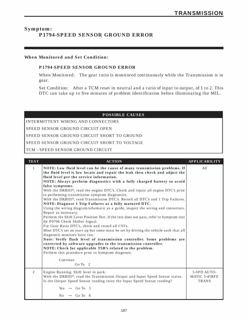
Symptom:P1794-SPEED SENSOR GROUND ERROR
When Monitored and Set Condition:
P1794-SPEED SENSOR GROUND ERROR
When Monitored: The gear ratio is monitored continuously while the Transmission is ingear.
Set Condition: After a TCM reset in neutral and a ratio of input to output, of 1 to 2. ThisDTC can take up to five minutes of problem identification before illuminating the MIL.
POSSIBLE CAUSES
INTERMITTENT WIRING AND CONNECTORS
SPEED SENSOR GROUND CIRCUIT OPEN
SPEED SENSOR GROUND CIRCUIT SHORT TO GROUND
SPEED SENSOR GROUND CIRCUIT SHORT TO VOLTAGE
TCM - SPEED SENSOR GROUND CIRCUIT
TEST ACTION APPLICABILITY
1 NOTE: Low fluid level can be the cause of many transmission problems. Ifthe fluid level is low locate and repair the leak then check and adjust thefluid level per the service information.NOTE: Always perform diagnostics with a fully charged battery to avoidfalse symptoms.With the DRBIIIt, read the engine DTC’s. Check and repair all engine DTC’s priorto performing transmission symptom diagnostics.With the DRBIIIt, read Transmission DTC’s. Record all DTC’s and 1 Trip Failures.NOTE: Diagnose 1 Trip Failures as a fully matured DTC.Using the wiring diagram/schematic as a guide, inspect the wiring and connectors.Repair as necessary.Perform the Shift Lever Position Test. If the test does not pass, refer to Symptom testfor P0706 Check Shifter Signal.For Gear Ratio DTC’s, check and record all CVI’s.Most DTC’s set on start up but some must be set by driving the vehicle such that alldiagnostic monitors have run.Note: Verify flash level of transmission controller. Some problems arecorrected by software upgrades to the transmission controller.NOTE: Check for applicable TSB’s related to the problem.Perform this procedure prior to Symptom diagnosis.
All
ContinueGo To 2
2 Engine Running. Shift lever in park.With the DRBIIIt, read the Transmission Output and Input Speed Sensor states.Is the Output Speed Sensor reading twice the Input Speed Sensor reading?
5-SPD AUTO-MATIC 5-45RFE
TRANS
Yes → Go To 3
No → Go To 8
187
TRANSMISSION

TEST ACTION APPLICABILITY
3 Turn the ignition off to the lock position.Remove the Starter Relay from the PDC.NOTE: Failure to remove the Starter Relay can cause a TCM - No Responsecondition.Install Transmission Simulator Miller tool 8333.Note: Check connectors - Clean/repair as necessary.Ignition on, engine not running.With the Transmission Simulator, set the Input/Output Speed selector switch to the93000/10009 position. Turn the Input/Output Speed switch to 9ON9.With the DRBIIIt, monitor the Input and Output Speed Sensor state.Does the input speed read 3000 RPM and the Output speed read 1000 RPM, within50 RPM?
5-SPD AUTO-MATIC 5-45RFE
TRANS
Yes → Go To 8
No → Go To 4
4 Turn the ignition off to the lock position.Disconnect the TCM harness connector.Disconnect the Input and Output Speed Sensor harness connector.Disconnect the Transmission Solenoid/TRS Assembly harness connector.Note: Check connectors - Clean/repair as necessary.Measure the resistance of the Speed Sensor Ground circuit from the TCM harnessconnector to the Transmission Solenoid/TRS Assembly, Input, and Output SpeedSensor harness connectors.Is the resistance above 5.0 ohms on any of the above measurements?
5-SPD AUTO-MATIC 5-45RFE
TRANS
Yes → Repair the Speed Sensor Ground circuit for an open.Perform 45RFE/545RFE TRANSMISSION VERIFICATIONTEST - VER 1.
No → Go To 5
5 Turn the ignition off to the lock position.Disconnect the TCM harness connector.Disconnect the Transmission Solenoid/TRS Assembly harness connector.Disconnect the Input and Output Speed Sensor harness connectors.Note: Check connectors - Clean/repair as necessary.Measure the resistance between the Input Sensor Ground circuit and ground.Is the resistance below 5.0 ohms?
5-SPD AUTO-MATIC 5-45RFE
TRANS
Yes → Repair the Speed Senor Ground circuit for a short to ground.Perform 45RFE/545RFE TRANSMISSION VERIFICATIONTEST - VER 1.
No → Go To 6
6 Turn the ignition off to the lock position.Disconnect the Input and Output Speed Sensors.Note: Check connectors - Clean/repair as necessary.Ignition on, engine not running.Measure the voltage of the Speed Sensor Ground circuit.Is the voltage above 0.5 volt?
5-SPD AUTO-MATIC 5-45RFE
TRANS
Yes → Repair the Speed Sensor Ground circuit for a short to voltage.Perform 45RFE/545RFE TRANSMISSION VERIFICATIONTEST - VER 1.
No → Go To 7
188
TRANSMISSION
P1794-SPEED SENSOR GROUND ERROR — Continued

TEST ACTION APPLICABILITY
7 If there are no possible causes remaining, view repair. 5-SPD AUTO-MATIC 5-45RFE
TRANS
RepairReplace the Transmission Control Module. WITH THE DRBIIItPERFORM QUICK LEARNPerform 45RFE/545RFE TRANSMISSION VERIFICATIONTEST - VER 1.
8 The conditions necessary to set this DTC are not present at this time.Using the schematics as a guide, inspect the wiring and connectors specific to thiscircuit.Wiggle the wires while checking for shorts and open circuits.Were there any problems found?
5-SPD AUTO-MATIC 5-45RFE
TRANS
Yes → Repair as necessary.Perform 45RFE/545RFE TRANSMISSION VERIFICATIONTEST - VER 1.
No → Test Complete.
189
TRANSMISSION
P1794-SPEED SENSOR GROUND ERROR — Continued

Symptom:P1799-CALCULATED OIL TEMP IN USE
When Monitored and Set Condition:
P1799-CALCULATED OIL TEMP IN USE
When Monitored: Whenever the engine is running.
Set Condition: The DTC will set if any of the three conditions are present. Thermistorvoltage (Transmission Temperature Sensor) out of range. Continuous erratic thermistorvoltage is sensed. Thermistor Temperature stays low for an extended period of time.
POSSIBLE CAUSES
INTERMITTENT WIRING & CONNECTORS
SPEED SENSOR GROUND CIRCUIT OPEN
TRANSMISSION TEMPERATURE SENSOR SIGNAL CIRCUIT OPEN
TRANSMISSION TEMPERATURE SENSOR SIGNAL CIRCUIT SHORT TO GROUND
SPEED SENSOR GROUND CIRCUIT SHORT TO VOLTAGE
TRANSMISSION TEMPERATURE SENSOR SIGNAL CIRCUIT SHORT TO VOLTAGE
TRANSMISSION TEMPERATURE SENSOR - INOPERATIVE
TCM - CALCULATED OIL TEMP IN USE
TCM - TRANSMISSION TEMPERATURE SENSOR HIGH
TCM - TRANSMISSION TEMPERATURE SENSOR LOW
TEST ACTION APPLICABILITY
1 NOTE: Low fluid level can be the cause of many transmission problems. Ifthe fluid level is low locate and repair the leak then check and adjust thefluid level per the service information.NOTE: Always perform diagnostics with a fully charged battery to avoidfalse symptoms.With the DRBIIIt, read the engine DTC’s. Check and repair all engine DTC’s priorto performing transmission symptom diagnostics.With the DRBIIIt, read Transmission DTC’s. Record all DTC’s and 1 Trip Failures.NOTE: Diagnose 1 Trip Failures as a fully matured DTC.Using the wiring diagram/schematic as a guide, inspect the wiring and connectors.Repair as necessary.Perform the Shift Lever Position Test. If the test does not pass, refer to Symptom testfor P0706 Check Shifter Signal.For Gear Ratio DTC’s, check and record all CVI’s.Most DTC’s set on start up but some must be set by driving the vehicle such that alldiagnostic monitors have run.Note: Verify flash level of transmission controller. Some problems arecorrected by software upgrades to the transmission controller.NOTE: Check for applicable TSB’s related to the problem.Perform this procedure prior to Symptom diagnosis.
All
ContinueGo To 2
190
TRANSMISSION

TEST ACTION APPLICABILITY
2 With the DRBIIIt, Check the STARTS SINCE SET counter.Note: This counter only applies to the last code set.Is the STARTS SINCE SET counter 2 or less?
5-SPD AUTO-MATIC 5-45RFE
TRANS
Yes → Go To 3
No → Go To 12
3 Turn the ignition off to the lock position.Remove the Starter Relay from the PDC.NOTE: Failure to remove Starter Relay can cause a TCM - No Responsecondition.Install Transmission Simulator, Miller tool #8333.Note: Check connectors - Clean/repair as necessary.Ignition on, engine not running.With the Transmission Simulator, turn the Input/Output switch to OFF.With the DRBIIIt, monitor the TRANS TEMP VOLTS while turning the ThermistorVoltage switch to all three positions on the Transmission Simulator.Compare the DRBIIIt readings with the numbers listed on the TransmissionSimulator.Pick one of the following that best matches your readings.
5-SPD AUTO-MATIC 5-45RFE
TRANS
DRBIIIt readings always high.Go To 4
DRBIIIt readings = simulator +/- 0.25 VGo To 9
DRBIIIt readings always lowGo To 10
DRBIIIt readings erratic.Go To 12
4 Turn the ignition off to the lock position.Disconnect the TCM harness connector.Disconnect the Transmission Solenoid /TRS Assembly harness connectorNote: Check connectors - Clean/repair as necessary.Measure the resistance of the Speed Sensor Ground circuit from the TCM harnessconnector to the Transmission Solenoid/TRS Assembly harness connector.Is the resistance above 5.0 ohms?
5-SPD AUTO-MATIC 5-45RFE
TRANS
Yes → Repair the Speed Sensor Ground circuit for an open.Perform 45RFE/545RFE TRANSMISSION VERIFICATIONTEST - VER 1.
No → Go To 5
191
TRANSMISSION
P1799-CALCULATED OIL TEMP IN USE — Continued

TEST ACTION APPLICABILITY
5 Turn the ignition off to the lock position.Disconnect the TCM harness connector..Disconnect the Transmission Solenoid /TRS Assembly harness connectorNote: Check connectors - Clean/repair as necessary.Measure the resistance of the Transmission Temperature Sensor Signal circuit fromthe TCM harness connector to the Transmission Solenoid/TRS Assembly harnessconnector.Is the resistance above 5.0 ohms?
5-SPD AUTO-MATIC 5-45RFE
TRANS
Yes → Repair the Transmission Temperature Sensor Signal circuit foran open.Perform 45RFE/545RFE TRANSMISSION VERIFICATIONTEST - VER 1.
No → Go To 6
6 Turn the ignition off to the lock position.Disconnect the Input and Output Speed Sensors.Note: Check connectors - Clean/repair as necessary.Ignition on, engine not running.Measure the voltage of the Speed Sensor Ground circuit.Is the voltage above 0.5 volt?
5-SPD AUTO-MATIC 5-45RFE
TRANS
Yes → Repair the Speed Sensor Ground circuit for a short to voltage.Perform 45RFE/545RFE TRANSMISSION VERIFICATIONTEST - VER 1.
No → Go To 7
7 Turn the ignition off to the lock position.Disconnect the TCM harness connector.Remove the Transmission Control Relay from the PDC.Note: Check connectors - Clean/repair as necessary.Connect a jumper wire between the Fused B(+) circuit and the Transmission ControlRelay Output circuit in the Transmission Control Relay connector.Ignition on, engine not running.Measure the voltage of the Transmission Temperature Sensor Signal circuit in theTCM harness connector.Is the voltage above 0.5 volts?
5-SPD AUTO-MATIC 5-45RFE
TRANS
Yes → Repair the Transmission Temperature Sensor Signal circuit for ashort to voltage.Perform 45RFE/545RFE TRANSMISSION VERIFICATIONTEST - VER 1.
No → Go To 8
8 If there are no possible causes remaining, view repair. 5-SPD AUTO-MATIC 5-45RFE
TRANS
RepairReplace the Transmission Control Module. WITH THE DRBIIItPERFORM QUICK LEARNPerform 45RFE/545RFE TRANSMISSION VERIFICATIONTEST - VER 1.
192
TRANSMISSION
P1799-CALCULATED OIL TEMP IN USE — Continued

TEST ACTION APPLICABILITY
9 If there are no possible causes remaining, view repair. 5-SPD AUTO-MATIC 5-45RFE
TRANS
RepairReplace Transmission Solenoid/TRS assembly as required.Perform 45RFE/545RFE TRANSMISSION VERIFICATIONTEST - VER 1.
10 Turn the ignition off to the lock position.Disconnect the TCM harness connector..Disconnect the Transmission Solenoid/TRS Assembly harness connector.Note: Check connectors - Clean/repair as necessary.Measure the resistance between ground and the Transmission Temperature SensorSignal circuit.Is the resistance below 5.0 ohms?
5-SPD AUTO-MATIC 5-45RFE
TRANS
Yes → Repair the Transmission Temperature Sensor Signal circuit for ashort to ground.Perform 45RFE/545RFE TRANSMISSION VERIFICATIONTEST - VER 1.
No → Go To 11
11 If there are no possible causes remaining, view repair. 5-SPD AUTO-MATIC 5-45RFE
TRANS
RepairReplace the Transmission Control Module. WITH THE DRBIIItPERFORM QUICK LEARNPerform 45RFE/545RFE TRANSMISSION VERIFICATIONTEST - VER 1.
12 Using the schematics as a guide, inspect the wiring and connectors specific to thiscircuit.Wiggle the wires while checking for shorts and open circuits.Check for any applicable TSB’s that may apply.Were there any problems found?
5-SPD AUTO-MATIC 5-45RFE
TRANS
Yes → Repair as necessary.Perform 45RFE/545RFE TRANSMISSION VERIFICATIONTEST - VER 1.
No → Go To 13
13 If there are no possible causes remaining, view repair. 5-SPD AUTO-MATIC 5-45RFE
TRANS
RepairReplace the Transmission Control Module. WITH THE DRBIIItPERFORM QUICK LEARNPerform 45RFE/545RFE TRANSMISSION VERIFICATIONTEST - VER 1.
193
TRANSMISSION
P1799-CALCULATED OIL TEMP IN USE — Continued

Symptom:P2700-INADEQUATE ELEMENT VOLUME LR
When Monitored and Set Condition:
P2700-INADEQUATE ELEMENT VOLUME LR
When Monitored: Whenever the engine is running. The LR volume is updated during a3-1 or 2-1 manual downshift with throttle angle below 5 degrees. Trans temp must be atleast 43 C (110 F)
Set Condition: When the LR volume falls below 16.
POSSIBLE CAUSES
INTERNAL TRANSMISSION - LR CLUTCH VOLUME INDEX LOW
TCM - LR CLUTCH VOLUME INDEX LOW
TEST ACTION APPLICABILITY
1 NOTE: Low fluid level can be the cause of many transmission problems. Ifthe fluid level is low locate and repair the leak then check and adjust thefluid level per the service information.NOTE: Always perform diagnostics with a fully charged battery to avoidfalse symptoms.With the DRBIIIt, read the engine DTC’s. Check and repair all engine DTC’s priorto performing transmission symptom diagnostics.With the DRBIIIt, read Transmission DTC’s. Record all DTC’s and 1 Trip Failures.NOTE: Diagnose 1 Trip Failures as a fully matured DTC.Using the wiring diagram/schematic as a guide, inspect the wiring and connectors.Repair as necessary.Perform the Shift Lever Position Test. If the test does not pass, refer to Symptom testfor P0706 Check Shifter Signal.For Gear Ratio DTC’s, check and record all CVI’s.Most DTC’s set on start up but some must be set by driving the vehicle such that alldiagnostic monitors have run.Note: Verify flash level of transmission controller. Some problems arecorrected by software upgrades to the transmission controller.NOTE: Check for applicable TSB’s related to the problem.Perform this procedure prior to Symptom diagnosis.
All
ContinueGo To 2
2 With the DRBIIIt, erase DTC9sNOTE: The TRANS TEMP DEG must be at least 43°C or 110°F beforeperforming the following steps.Drive the vehicle and perform at least ten 3-1 manual downshifts at closed throttlefrom speeds of about 32 km/h or 20 MPH.With the DRBIIIt, read the LR CL VOL INDEX.Is the LR CL VOL INDEX below 20?
5-SPD AUTO-MATIC 5-45RFE
TRANS
Yes → Go To 3
No → Go To 4
194
TRANSMISSION

TEST ACTION APPLICABILITY
3 If there are no possible causes remaining, view repair. 5-SPD AUTO-MATIC 5-45RFE
TRANS
RepairRepair internal transmission as necessary. Refer to the ServiceInformation for the proper repair procedure for components re-lated to the LR clutch. A broken or weak return spring or adislocated snap ring could cause this problem.Perform 45RFE/545RFE TRANSMISSION VERIFICATIONTEST - VER 1.
4 NOTE: The TRANS TEMP DEG must be at least 43° C or 110° F beforeperforming the following steps.Perform eight learnable starts. A learnable start is defined as follows: Start engine.From a standstill, accelerate lightly to 80 km/h or 50 MPH, then brake lightly to astop. Turn off engine.With the DRBIIIt, record the CL VOL INDEX (CVI) for all clutches.With the DRBIIIt, perform a BATTERY DISCONNECT.With the DRBIIIt, read the CVI’s and compare them to the readings recorded beforethe BATTERY DISCONNECT.Are any of the CVI’s less than 5 or different than before the BATTERY DISCON-NECT?
5-SPD AUTO-MATIC 5-45RFE
TRANS
Yes → Go To 5
No → Test Complete.
5 If there are no possible causes remaining, view repair. 5-SPD AUTO-MATIC 5-45RFE
TRANS
RepairReplace the Transmission Control Module. WITH THE DRBIIItPERFORM QUICK LEARNPerform 45RFE/545RFE TRANSMISSION VERIFICATIONTEST - VER 1.
195
TRANSMISSION
P2700-INADEQUATE ELEMENT VOLUME LR — Continued

Symptom:P2701-INADEQUATE ELEMENT VOLUME 2C
When Monitored and Set Condition:
P2701-INADEQUATE ELEMENT VOLUME 2C
When Monitored: Whenever the engine is running. The 2C volume is updated during a3-2 kickdown with throttle angle between 10 and 54 degrees. Trans temp must be at least43 C (110 F)
Set Condition: When the 2C volume falls below 5.
POSSIBLE CAUSES
INTERNAL TRANSMISSION - 2C CLUTCH VOLUME INDEX LOW
TCM - 2C CLUTCH VOLUME INDEX LOW
TEST ACTION APPLICABILITY
1 NOTE: Low fluid level can be the cause of many transmission problems. Ifthe fluid level is low locate and repair the leak then check and adjust thefluid level per the service information.NOTE: Always perform diagnostics with a fully charged battery to avoidfalse symptoms.With the DRBIIIt, read the engine DTC’s. Check and repair all engine DTC’s priorto performing transmission symptom diagnostics.With the DRBIIIt, read Transmission DTC’s. Record all DTC’s and 1 Trip Failures.NOTE: Diagnose 1 Trip Failures as a fully matured DTC.Using the wiring diagram/schematic as a guide, inspect the wiring and connectors.Repair as necessary.Perform the Shift Lever Position Test. If the test does not pass, refer to Symptom testfor P0706 Check Shifter Signal.For Gear Ratio DTC’s, check and record all CVI’s.Most DTC’s set on start up but some must be set by driving the vehicle such that alldiagnostic monitors have run.Note: Verify flash level of transmission controller. Some problems arecorrected by software upgrades to the transmission controller.NOTE: Check for applicable TSB’s related to the problem.Perform this procedure prior to Symptom diagnosis.
All
ContinueGo To 2
196
TRANSMISSION

TEST ACTION APPLICABILITY
2 With the DRBIIIt, erase DTC9sDrive the vehicle at about 80 km/h or 50 MPH, then depress the OD off button. Thiswill put the vehicle into third gear.NOTE: The TRANS TEMP DEG must be at least 43° C or 110° F beforeperforming the following steps.Perform at least ten 3-2 kickdowns by depressing the throttle between 10 and 54 TPSDEGREES at speeds of about 80 km/h or 50 MPH.With the DRBIIIt, read the 2C CL VOL INDEX.Is the 2C CL VOL INDEX below 10?
5-SPD AUTO-MATIC 5-45RFE
TRANS
Yes → Go To 3
No → Go To 4
3 If there are no possible causes remaining, view repair. 5-SPD AUTO-MATIC 5-45RFE
TRANS
RepairRepair internal transmission as necessary. Refer to the ServiceInformation for the proper repair procedure for components re-lated to the 2C clutch. A broken or weak return spring or adislocated snap ring could cause this problem.Perform 45RFE/545RFE TRANSMISSION VERIFICATIONTEST - VER 1.
4 NOTE: The TRANS TEMP DEG must be at least 43° C or 110° F beforeperforming the following steps.Perform eight learnable starts. A learnable start is defined as follows: Start engine.From a standstill, accelerate lightly to 80 km/h or 50 MPH, then brake lightly to astop. Turn off engine.With the DRBIIIt, record the CL VOL INDEX (CVI) for all clutchesWith the DRBIIIt, perform a BATTERY DISCONNECT.With the DRBIIIt, read the CVI’s and compare them to the readings recorded beforethe BATTERY DISCONNECT.Are any of the CVI’s less than 5 or different than before the BATTERY DISCON-NECT?
5-SPD AUTO-MATIC 5-45RFE
TRANS
Yes → Go To 5
No → Test Complete.
5 If there are no possible causes remaining, view repair. 5-SPD AUTO-MATIC 5-45RFE
TRANS
RepairReplace the Transmission Control Module. WITH THE DRBIIItPERFORM QUICK LEARNPerform 45RFE/545RFE TRANSMISSION VERIFICATIONTEST - VER 1.
197
TRANSMISSION
P2701-INADEQUATE ELEMENT VOLUME 2C — Continued

Symptom:P2702-INADEQUATE ELEMENT VOLUME OD
When Monitored and Set Condition:
P2702-INADEQUATE ELEMENT VOLUME OD
When Monitored: Whenever the engine is running. The OD volume is updated during a2-3 upshift with throttle angle between 10 and 54 degrees. Trans temp must be at least 43C (110 F)
Set Condition: When the OD volume falls below 5.
POSSIBLE CAUSES
INTERNAL TRANSMISSION - O/D CLUTCH VOLUME INDEX LOW
TCM- OD CLUTCH VOLUME INDEX LOW
TEST ACTION APPLICABILITY
1 NOTE: Low fluid level can be the cause of many transmission problems. Ifthe fluid level is low locate and repair the leak then check and adjust thefluid level per the service information.NOTE: Always perform diagnostics with a fully charged battery to avoidfalse symptoms.With the DRBIIIt, read the engine DTC’s. Check and repair all engine DTC’s priorto performing transmission symptom diagnostics.With the DRBIIIt, read Transmission DTC’s. Record all DTC’s and 1 Trip Failures.NOTE: Diagnose 1 Trip Failures as a fully matured DTC.Using the wiring diagram/schematic as a guide, inspect the wiring and connectors.Repair as necessary.Perform the Shift Lever Position Test. If the test does not pass, refer to Symptom testfor P0706 Check Shifter Signal.For Gear Ratio DTC’s, check and record all CVI’s.Most DTC’s set on start up but some must be set by driving the vehicle such that alldiagnostic monitors have run.Note: Verify flash level of transmission controller. Some problems arecorrected by software upgrades to the transmission controller.NOTE: Check for applicable TSB’s related to the problem.Perform this procedure prior to Symptom diagnosis.
All
ContinueGo To 2
2 With the DRBIIIt, erase DTC9sNOTE: The TRANS TEMP DEG must be at least 43° C or 110° F beforeperforming the following steps.Drive the vehicle and perform at least ten 2-3 upshifts with the throttle between 10and 54 TPS DEGREES.With the DRBIIIt, read the OD CL VOL INDEX.Is the OD CL VOL INDEX below 10?
5-SPD AUTO-MATIC 5-45RFE
TRANS
Yes → Go To 3
No → Go To 4
198
TRANSMISSION

TEST ACTION APPLICABILITY
3 If there are no possible causes remaining, view repair. 5-SPD AUTO-MATIC 5-45RFE
TRANS
RepairRepair internal transmission as necessary. Refer to the ServiceInformation for the proper repair procedure for components re-lated to the OD clutch. A broken or weak return spring or adislocated snap ring could cause this problem.Perform 45RFE/545RFE TRANSMISSION VERIFICATIONTEST - VER 1.
4 NOTE: The TRANS TEMP DEG must be at least 43° C or 110° F beforeperforming the following steps.Perform eight learnable starts. A learnable start is defined as follows: Start engine.From a standstill, accelerate lightly to 80 km/h or 50 MPH, then brake lightly to astop. Turn off engine.With the DRBIIIt, record the CL VOL INDEX (CVI) for all clutches.With the DRBIIIt, perform a BATTERY DISCONNECT.With the DRBIIIt, read the CVI’s and compare them to the readings recorded beforethe BATTERY DISCONNECT.Are any of the CVI’s less than 5 or different than before the BATTERY DISCON-NECT?
5-SPD AUTO-MATIC 5-45RFE
TRANS
Yes → Go To 5
No → Test Complete.
5 If there are no possible causes remaining, view repair. 5-SPD AUTO-MATIC 5-45RFE
TRANS
RepairReplace the Transmission Control Module. WITH THE DRBIIItPERFORM QUICK LEARNPerform 45RFE/545RFE TRANSMISSION VERIFICATIONTEST - VER 1.
199
TRANSMISSION
P2702-INADEQUATE ELEMENT VOLUME OD — Continued

Symptom:P2703- INADEQUATE ELEMENT VOLUME UD
When Monitored and Set Condition:
P2703- INADEQUATE ELEMENT VOLUME UD
When Monitored: Whenever the engine is running. The UD volume is updated during a4-3 kickdown with throttle angle between 10 and 54 degrees. Trans temp must be at least43 C (110 F)
Set Condition: When the UD volume falls below 11.
POSSIBLE CAUSES
INTERNAL TRANSMISSION - UD CLUTCH VOLUME INDEX LOW
TCM- UD CLUTCH VOLUME INDEX LOW
TEST ACTION APPLICABILITY
1 NOTE: Low fluid level can be the cause of many transmission problems. Ifthe fluid level is low locate and repair the leak then check and adjust thefluid level per the service information.NOTE: Always perform diagnostics with a fully charged battery to avoidfalse symptoms.With the DRBIIIt, read the engine DTC’s. Check and repair all engine DTC’s priorto performing transmission symptom diagnostics.With the DRBIIIt, read Transmission DTC’s. Record all DTC’s and 1 Trip Failures.NOTE: Diagnose 1 Trip Failures as a fully matured DTC.Using the wiring diagram/schematic as a guide, inspect the wiring and connectors.Repair as necessary.Perform the Shift Lever Position Test. If the test does not pass, refer to Symptom testfor P0706 Check Shifter Signal.For Gear Ratio DTC’s, check and record all CVI’s.Most DTC’s set on start up but some must be set by driving the vehicle such that alldiagnostic monitors have run.Note: Verify flash level of transmission controller. Some problems arecorrected by software upgrades to the transmission controller.NOTE: Check for applicable TSB’s related to the problem.Perform this procedure prior to Symptom diagnosis.
All
ContinueGo To 2
2 With the DRBIIIt, erase DTC9sNOTE: The TRANS TEMP DEG must be at least 43° C or 110° F beforeperforming the following steps.Drive the vehicle and perform at least ten 4-3 kickdowns by depressing the throttlebetween 30 and 54 TPS DEGREES at speeds about 80 km/h or 50 MPH.With the DRBIIIt, read the UD CL VOL INDEX.Is the UD CL VOL INDEX below 10?
5-SPD AUTO-MATIC 5-45RFE
TRANS
Yes → Go To 3
No → Go To 4
200
TRANSMISSION

TEST ACTION APPLICABILITY
3 If there are no possible causes remaining, view repair. 5-SPD AUTO-MATIC 5-45RFE
TRANS
RepairRepair internal transmission as necessary. Refer to the ServiceInformation for the proper repair procedure for components re-lated to the UD clutch. A broken or weak return spring or adislocated snap ring could cause this problem.Perform 45RFE/545RFE TRANSMISSION VERIFICATIONTEST - VER 1.
4 NOTE: The TRANS TEMP DEG must be at least 43° C or 110° F beforeperforming the following steps.Perform eight learnable starts. A learnable start is defined as follows: Start engine.From a standstill, accelerate lightly to 80 km/h or 50 MPH, then brake lightly to astop. Turn off engine.With the DRBIIIt, record CL VOL INDEX (CVI) for all clutches.With the DRBIIIt, perform a BATTERY DISCONNECT.With the DRBIIIt, read the CVI’s and compare them to the readings recorded beforethe BATTERY DISCONNECT.Are any of the CVI’s less than 5 or different than before the BATTERY DISCON-NECT?
5-SPD AUTO-MATIC 5-45RFE
TRANS
Yes → Go To 5
No → Test Complete.
5 If there are no possible causes remaining, view repair. 5-SPD AUTO-MATIC 5-45RFE
TRANS
RepairReplace the Transmission Control Module. WITH THE DRBIIItPERFORM QUICK LEARNPerform 45RFE/545RFE TRANSMISSION VERIFICATIONTEST - VER 1.
201
TRANSMISSION
P2703- INADEQUATE ELEMENT VOLUME UD — Continued

Symptom:P2704-INADEQUATE ELEMENT VOLUME 4C
When Monitored and Set Condition:
P2704-INADEQUATE ELEMENT VOLUME 4C
When Monitored: Whenever the engine is running. The 4C volume is updated during a3-4 upshift with throttle angle between 10 and 54 degrees. Trans temp must be at least 43C (110 F)
Set Condition: When the 4C volume falls below 5.
POSSIBLE CAUSES
INTERNAL TRANSMISSION - 4C CLUTCH VOLUME LOW
TCM- 4C VOLUME LOW
TEST ACTION APPLICABILITY
1 NOTE: Low fluid level can be the cause of many transmission problems. Ifthe fluid level is low locate and repair the leak then check and adjust thefluid level per the service information.NOTE: Always perform diagnostics with a fully charged battery to avoidfalse symptoms.With the DRBIIIt, read the engine DTC’s. Check and repair all engine DTC’s priorto performing transmission symptom diagnostics.With the DRBIIIt, read Transmission DTC’s. Record all DTC’s and 1 Trip Failures.NOTE: Diagnose 1 Trip Failures as a fully matured DTC.Using the wiring diagram/schematic as a guide, inspect the wiring and connectors.Repair as necessary.Perform the Shift Lever Position Test. If the test does not pass, refer to Symptom testfor P0706 Check Shifter Signal.For Gear Ratio DTC’s, check and record all CVI’s.Most DTC’s set on start up but some must be set by driving the vehicle such that alldiagnostic monitors have run.Note: Verify flash level of transmission controller. Some problems arecorrected by software upgrades to the transmission controller.NOTE: Check for applicable TSB’s related to the problem.Perform this procedure prior to Symptom diagnosis.
All
ContinueGo To 2
202
TRANSMISSION

TEST ACTION APPLICABILITY
2 NOTE: Check the Transmission Fluid Level. If the Transmission Fluid is low,repair any Transmission Fluid leak as necessary and adjust the Transmis-sion Fluid Level per the Service Information.With the DRBIIIt, record the 4C CL VOL INDEX.With the DRBIIIt, erase DTC’s.Perform at least 10 3-4 upshifts with the throttle between 10 and 54 degrees. TheTransmission Temperature must be at least 43°C or 110 °F.With the DRBIIIt, read the 4C CL VOL INDEX.Is the current 4C CL VOL INDEX below 10?
5-SPD AUTO-MATIC 5-45RFE
TRANS
Yes → Go To 3
No → Go To 4
3 If there are no possible causes remaining, view repair. 5-SPD AUTO-MATIC 5-45RFE
TRANS
RepairRepair or replace the transmission as necessary per the ServiceInformation. Pay special attention to the mechanical componentsrelated to the 4th clutch. A deteriorated return spring or adislocated snap ring could cause this problem.Perform 45RFE/545RFE TRANSMISSION VERIFICATIONTEST - VER 1.
4 Perform eight learnable starts. A learnable start is defined as follows: Start engine.From a standstill, accelerate lightly to 50 MPH, then brake lightly to a stop. Turn offengine.With the DRBIIIt, observe and record CVI’s.With the DRBIIIt, perform a battery disconnect.With the DRBIIIt, Observe CVI’sAre any of the CVI’s less than 5 or are they different than before the batterydisconnect?
5-SPD AUTO-MATIC 5-45RFE
TRANS
Yes → Go To 5
No → Test Complete.
5 If there are no possible causes remaining, view repair. 5-SPD AUTO-MATIC 5-45RFE
TRANS
RepairReplace the Transmission Control Module. WITH THE DRBIIItPERFORM QUICK LEARNPerform 45RFE/545RFE TRANSMISSION VERIFICATIONTEST - VER 1.
203
TRANSMISSION
P2704-INADEQUATE ELEMENT VOLUME 4C — Continued

Symptom:P2706-MS SOLENOID CIRCUIT
When Monitored and Set Condition:
P2706-MS SOLENOID CIRCUIT
When Monitored: Initially at power-up, then every 10 seconds thereafter. They will alsobe tested immediately after a gear ratio or pressure switch error is detected.
Set Condition: Three consecutive solenoid continuity test failures, or one failure if test isrun in response to a gear ratio or pressure switch error.
POSSIBLE CAUSES
RELATED RELAY DTC’S PRESENT
INTERMITTENT WIRING AND CONNECTORS
MS SOLENOID CONTROL CIRCUIT OPEN
TRANSMISSION CONTROL RELAY OUTPUT CIRCUIT OPEN
MS SOLENOID CONTROL CIRCUIT SHORT TO GROUND
MS SOLENOID CIRCUIT SHORT TO VOLTAGE
MS SOLENOID INOPERATIVE
TCM - MS SOLENOID CIRCUIT
TEST ACTION APPLICABILITY
1 NOTE: Low fluid level can be the cause of many transmission problems. Ifthe fluid level is low locate and repair the leak then check and adjust thefluid level per the service information.NOTE: Always perform diagnostics with a fully charged battery to avoidfalse symptoms.With the DRBIIIt, read the engine DTC’s. Check and repair all engine DTC’s priorto performing transmission symptom diagnostics.With the DRBIIIt, read Transmission DTC’s. Record all DTC’s and 1 Trip Failures.NOTE: Diagnose 1 Trip Failures as a fully matured DTC.Using the wiring diagram/schematic as a guide, inspect the wiring and connectors.Repair as necessary.Perform the Shift Lever Position Test. If the test does not pass, refer to Symptom testfor P0706 Check Shifter Signal.For Gear Ratio DTC’s, check and record all CVI’s.Most DTC’s set on start up but some must be set by driving the vehicle such that alldiagnostic monitors have run.Note: Verify flash level of transmission controller. Some problems arecorrected by software upgrades to the transmission controller.NOTE: Check for applicable TSB’s related to the problem.Perform this procedure prior to Symptom diagnosis.
All
ContinueGo To 2
204
TRANSMISSION

TEST ACTION APPLICABILITY
2 With the DRBIIIt, check for other transmission DTC’s.Are there any Transmission Control Relay related DTCs P0890, P0891, and/or P0888present?
5-SPD AUTO-MATIC 5-45RFE
TRANS
Yes → Refer to symptom list and perform test for Transmission ControlRelay related DTCs.Perform 45RFE/545RFE TRANSMISSION VERIFICATIONTEST - VER 1.
No → Go To 3
3 With the DRBIIIt, Check the STARTS SINCE SET counter for P2706.NOTE: This counter only applies to the last DTC set.Is the STARTS SINCE SET counter for P2706 set at 0?
5-SPD AUTO-MATIC 5-45RFE
TRANS
Yes → Go To 4
No → Go To 11
4 Turn the ignition off to the lock position.Remove the Starter Relay from the PDC.NOTE: Failure to remove the Starter Relay can cause a TCM - No Responsecondition.Install the Transmission Simulator, Miller tool #8333.Note: Check connectors - Clean/repair as necessary.Ignition on, engine not running..With the DRBIIIt, actuate the MS Solenoid.Monitor the MS Solenoid LED on the Transmission Simulator.Did the LED on the Transmission Simulator blink on and off?
5-SPD AUTO-MATIC 5-45RFE
TRANS
Yes → Go To 5
No → Go To 6
5 If there are no possible causes remaining, view repair. 5-SPD AUTO-MATIC 5-45RFE
TRANS
RepairReplace Transmission Solenoid/TRS Assembly as required.Perform 45RFE/545RFE TRANSMISSION VERIFICATIONTEST - VER 1.
6 Turn the ignition off to the lock position.Disconnect the TCM harness connector.Disconnect the Transmission Solenoid /TRS Assembly harness connectorNote: Check connectors - Clean/repair as necessary.Measure the resistance of the MS Solenoid Control circuit between the TCM harnessconnector to the Transmission Solenoid/TRS Assembly harness connector.Is the resistance above 5.0 ohms?
5-SPD AUTO-MATIC 5-45RFE
TRANS
Yes → Repair the MS Solenoid Control circuit for an open.Perform 45RFE/545RFE TRANSMISSION VERIFICATIONTEST - VER 1.
No → Go To 7
205
TRANSMISSION
P2706-MS SOLENOID CIRCUIT — Continued

TEST ACTION APPLICABILITY
7 Turn the ignition off to the lock position.Disconnect the Transmission Solenoid/TRS Assembly harness connector.Ignition on, engine not running.Using a 12-volt test light connected to ground, check the Transmission Control RelayOutput circuit in the Solenoid/TRS harness connector.NOTE: The test light must illuminate brightly. Compare the brightness tothat of a direct connection to the battery.Does the test light illuminate brightly?
5-SPD AUTO-MATIC 5-45RFE
TRANS
Yes → Go To 8
No → Repair the Transmission Control Relay Output circuit for anopen. If the fuse is open make sure to check for a short to ground.Perform 45RFE/545RFE TRANSMISSION VERIFICATIONTEST - VER 1.
8 Turn the ignition off to the lock position.Disconnect the TCM harness connector.Disconnect the Transmission Solenoid/TRS Assembly harness connector.Note: Check connectors - Clean/repair as necessary.Measure the resistance between ground and the MS Solenoid Control circuit.Is the resistance below 5.0 ohms?
5-SPD AUTO-MATIC 5-45RFE
TRANS
Yes → Repair the MS Solenoid Control circuit for a short to ground.Perform 45RFE/545RFE TRANSMISSION VERIFICATIONTEST - VER 1.
No → Go To 9
9 Turn the ignition off to the lock position.Disconnect the TCM harness connector.Disconnect the Transmission Solenoid/TRS Assembly harness connector.Remove the Transmission Control Relay from the PDC.Note: Check connectors - Clean/repair as necessary.Connect a jumper wire between the Fused B+ circuit and the Transmission ControlRelay Output circuit in the Transmission Control Relay connector.Ignition on, engine not running.Measure the voltage of the MS Solenoid Control circuit in the TCM harnessconnector.Is the voltage above 0.5 volt?
5-SPD AUTO-MATIC 5-45RFE
TRANS
Yes → Repair the MS Solenoid Control circuit for a short to voltage.Perform 45RFE/545RFE TRANSMISSION VERIFICATIONTEST - VER 1.
No → Go To 10
10 If there are no possible causes remaining, view repair. 5-SPD AUTO-MATIC 5-45RFE
TRANS
RepairReplace the Transmission Control Module. WITH THE DRBIIItPERFORM QUICK LEARNPerform 45RFE/545RFE TRANSMISSION VERIFICATIONTEST - VER 1.
206
TRANSMISSION
P2706-MS SOLENOID CIRCUIT — Continued

TEST ACTION APPLICABILITY
11 The conditions necessary to set this DTC are not present at this time.Using the wiring diagram/schematic as a guide, inspect the wiring and connectors.Check for any applicable TSB that may apply.Wiggle the wires while checking for shorts or open circuits.Were there any problems found?
5-SPD AUTO-MATIC 5-45RFE
TRANS
Yes → Repair as necessary.Perform 45RFE/545RFE TRANSMISSION VERIFICATIONTEST - VER 1.
No → Test Complete.
207
TRANSMISSION
P2706-MS SOLENOID CIRCUIT — Continued

Symptom:*BACKUP LAMPS COME ON WHILE SHIFTER IS NOT IN REVERSEPOSITION
POSSIBLE CAUSES
BACKUP SUPPLY CIRCUIT SHORT TO VOLTAGE
TRANSMISSION RANGE SENSOR
TEST ACTION APPLICABILITY
1 Ignition on, engine not running.Firmly apply brakes.Place the Shift Lever in the position which causes the Backup Lamps to come on atthe wrong time.Do the Backup Lamps come while the shifter is not in Reverse?
5-SPD AUTO-MATIC 5-45RFE
TRANS
Yes → Go To 2
No → Test Complete.
2 Ignition on, engine not running.Place the shift lever in a position that causes the Backup Lamps to come on whenthey should not.Disconnect the Transmission Solenoid /TRS Assembly harness connector.NOTE: This will cause a DTC to be stored in the TCM. They must be erasedbefore returning the vehicle to the customer.Did the Backup Lamps go out when the connector was disconnected?
5-SPD AUTO-MATIC 5-45RFE
TRANS
Yes → Go To 3
No → Go To 4
3 If there are no possible causes remaining, view repair. 5-SPD AUTO-MATIC 5-45RFE
TRANS
RepairReplace Transmission Solenoid/TRS Assembly as required.Perform 45RFE/545RFE TRANSMISSION VERIFICATIONTEST - VER 1.
4 Turn the ignition off to the lock position.Disconnect the Transmission Solenoid/TRS Assembly harness connector.Ignition on, engine not running.Measure the voltage of the Backup Light Supply circuit in the Solenoid/TRS harnessconnector.Is the voltage above 0.5 volt?
5-SPD AUTO-MATIC 5-45RFE
TRANS
Yes → Repair the Backup Lights Supply circuit for a short to voltage.Perform 45RFE/545RFE TRANSMISSION VERIFICATIONTEST - VER 1.
No → Test Complete.
208
TRANSMISSION

Symptom:*BACKUP LAMPS INOPERATIVE
POSSIBLE CAUSES
BACK UP LAMP GROUND CIRCUIT OPEN
BACKUP LAMP SUPPLY CIRCUIT OPEN
FUSED IGNITION SWITCH OUTPUT CIRCUIT OPEN
BACKUP LAMP SUPPLY CIRCUIT SHORT TO GROUND
OPEN BACKUP LAMP BULBS
TRANSMISSION RANGE SENSOR
TEST ACTION APPLICABILITY
1 Ignition on, engine not running.Place foot firmly on brake pedal.Place the shift lever in the reverse position.Do either of the Backup Lamps work?
5-SPD AUTO-MATIC 5-45RFE
TRANS
Yes → Test Complete.
No → Go To 2
2 Turn the ignition off to the lock position.Install Transmission Simulator Miller tool #8333.Ignition on, engine not running.Press the Reverse Light Test button on the Transmission Simulator while observingthe Backup Lamps.Do either of the Backup Lamps come on?
5-SPD AUTO-MATIC 5-45RFE
TRANS
Yes → Go To 3
No → Go To 4
3 If there are no possible causes remaining, view repair. 5-SPD AUTO-MATIC 5-45RFE
TRANS
RepairReplace Transmission Solenoid/TRS Assembly as required.
4 Remove the Backup Lamp bulb.Using a 12-volt test light connected to 12-volts, check the Backup Lamp groundcircuit.Does the light illuminate brightly?
5-SPD AUTO-MATIC 5-45RFE
TRANS
Yes → Go To 5
No → Repair the bad ground circuit to the Back up Lamp bulb socket.
5 Remove both Backup Lamp bulbs.Measure the resistance of both Backup Lamp bulbs.Is the resistance above 5.0 ohms for either Backup Lamp bulbs?
5-SPD AUTO-MATIC 5-45RFE
TRANS
Yes → Replace the Backup Lamp bulb or bulbs as required.
No → Go To 6
209
TRANSMISSION

TEST ACTION APPLICABILITY
6 Turn the ignition off to the lock position.Remove the Backup Lamp bulb.Disconnect the Transmission Solenoid /TRS Assembly harness connector.Measure the resistance of the Backup Lamp Supply circuit from the Backup lampSocket to the Solenoid/TRS connector.Is the resistance above 5.0 ohms?
5-SPD AUTO-MATIC 5-45RFE
TRANS
Yes → Repair the Backup Lamp circuit for an open.
No → Go To 7
7 Turn the ignition off to the lock position.Disconnect the Transmission Solenoid /TRS harness connector.Ignition on, engine not running.Using a 12-volt test light connected to ground, check the Fused Ignition SwitchOutput circuit.Does the light illuminate brightly?
5-SPD AUTO-MATIC 5-45RFE
TRANS
Yes → Go To 8
No → Repair the Fused Ignition Switch Output circuit for an open.Check fuse and replace, if necessary repair cause of open fuse.Possible short to ground or excessive resistance.
8 Turn the ignition off to the lock position.Remove the Backup Lamp bulb.Disconnect the Transmission Solenoid/TRS connector.Measure the resistance between the Backup Lamp Supply circuit and ground.Is the resistance below 5.0 ohms?
5-SPD AUTO-MATIC 5-45RFE
TRANS
Yes → Repair the Backup Supply Lamp circuit for a short to ground..Check fuse and replace if necessary.
No → Test Complete.
210
TRANSMISSION
*BACKUP LAMPS INOPERATIVE — Continued

Symptom:*BUMP FELT SHORTLY AFTER STOP WITH NO DTC’S PRESENT
POSSIBLE CAUSES
STICKING SLIP JOINT
TEST ACTION APPLICABILITY
1 This condition is normally caused by a stick and slip condition between the prop shaftslip joint and the transfer case output shaft.If there are no possible causes remaining, view repair.
5-SPD AUTO-MATIC 5-45RFE
TRANS
RepairCheck for TSB’s relating to this condition.
211
TRANSMISSION

Symptom:*BUMP FELT WHILE COASTING IN NEUTRAL WITH NO DTC’SPRESENT
TEST ACTION APPLICABILITY
1 Check for a TCM flash update or TSB to address this issue.Perform the drive learn procedure for the LR clutch element.NOTE: Some bump while coasting in neutral is normal.Perform the above procedures to reduce excessive bump in neutral.
5-SPD AUTO-MATIC 5-45RFE
TRANS
RepairTest Complete.
212
TRANSMISSION

Symptom:*CHECKING PARK/NEUTRAL SWITCH OPERATION
POSSIBLE CAUSES
INTERMITTENT WIRING AND CONNECTORS
PARK/NEUTRAL SWITCH SENSE CIRCUIT OPEN
PARK/NEUTRAL SWITCH SENSE CIRCUIT SHORT TO GROUND
PARK/NEUTRAL POSITION SWITCH
POWERTRAIN CONTROL MODULE - PARK NEUTRAL SWITCH
TEST ACTION APPLICABILITY
1 Ignition on, engine not running.With the DRBIIIt, monitor the PNP Switch Input status.Move the gear selector through all gear positions, Park to 1st and back to Park.Did the DRB display P/N and D/R in the correct gear positions?
5-SPD AUTO-MATIC 5-45RFE
TRANS
Yes → Go To 2
No → Go To 3
2 The condition is not present at this time. Using the schematics as a guide, inspect thewiring and connectors specific to this circuit. Wiggle the wires while checking forshorts and open circuits.Were there any problems found?
5-SPD AUTO-MATIC 5-45RFE
TRANS
Yes → Repair as necessary.Perform 45RFE/545RFE TRANSMISSION VERIFICATIONTEST - VER 1.
No → Test Complete.
3 Turn the ignition off to the lock position.Disconnect the PCM harness connector.Disconnect the PNP Switch harness connector.Check connectors - Clean/repair as necessaryMeasure the resistance of the PNP Switch Sense circuit between the PCM harnessconnector and the PNP Switch harness connector.Is the resistance below 5.0 ohms?
5-SPD AUTO-MATIC 5-45RFE
TRANS
Yes → Go To 4
No → Repair the PNP switch sense circuit for an open.Perform 45RFE/545RFE TRANSMISSION VERIFICATIONTEST - VER 1.
4 Ignition on, engine not running.Disconnect the PCM harness connector.Disconnect the PNP Switch harness connector.Check connectors - Clean/repair as necessaryMeasure the resistance between the PNP Switch Sense Circuit and ground.Is the resistance below 5.0 ohms?
5-SPD AUTO-MATIC 5-45RFE
TRANS
Yes → Repair the PNP switch sense circuit for a short to ground.Perform 45RFE/545RFE TRANSMISSION VERIFICATIONTEST - VER 1.
No → Go To 5
213
TRANSMISSION

TEST ACTION APPLICABILITY
5 Turn the ignition off to the lock position.Disconnect the PCM harness connector.Check connectors - Clean/repair as necessaryMove the gear selector through all gear positions, from Park to 1st and back.While moving the gear selector through the gear positions, measure the resistancebetween ground and the PNP Switch Sense circuit in the PCM harness connector.Did the display change from above 10.0 ohms to below 10.0 ohms?
5-SPD AUTO-MATIC 5-45RFE
TRANS
Yes → Go To 6
No → Replace the Park/Neutral Position Switch in accordance with theService Information.Perform 45RFE/545RFE TRANSMISSION VERIFICATIONTEST - VER 1.
6 If there are no possible causes remaining, view repair. 5-SPD AUTO-MATIC 5-45RFE
TRANS
RepairReplace the Powertrain Control Module.Perform 45RFE/545RFE TRANSMISSION VERIFICATIONTEST - VER 1.
214
TRANSMISSION
*CHECKING PARK/NEUTRAL SWITCH OPERATION — Continued

Symptom:*POOR SHIFT QUALITY
POSSIBLE CAUSES
POOR SHIFT QUALITY
TEST ACTION APPLICABILITY
1 Check the transmission fluid level per the service information.Is the fluid level ok?
5-SPD AUTO-MATIC 5-45RFE
TRANS
Yes → Test Complete.
No → Correct the fluid level as necessary. Check and repair all leaks inthe transmission if the fluid level is low. Note: This is one possiblecause of poor shift quality.Perform 45RFE/545RFE TRANSMISSION VERIFICATIONTEST - VER 1.
215
TRANSMISSION

Symptom:*TRANSMISSION NOISY WITH NO DTC’S PRESENT
POSSIBLE CAUSES
INCORRECT FLUID LEVEL
INTERNAL TRANSMISSION PROBLEM - NOISY WHILE DRIVING
INTERNAL TRANSMISSION PROBLEM - NOISY WHILE STANDING STILL
TEST ACTION APPLICABILITY
1 Check and adjust the oil level per the service information before continuing.Place vehicle on hoist.Run vehicle on hoist under conditions necessary to duplicate the noise.Using Chassis Ears or other suitable device, verify that the noise is coming from thetransmission.Is the noise coming from the transmission?
5-SPD AUTO-MATIC 5-45RFE
TRANS
Yes → Go To 2
No → Test Complete.
2 Check the transmission fluid level per the Service Information.NOTE: The transmission must be hot when checking oil level. When thetemperature is below 10° Celsius 50° Fahrenheit it is possible that no oil willshow on the dipstick, even though the transmission has an adequate filllevel when warm.Is the fluid level OK?
5-SPD AUTO-MATIC 5-45RFE
TRANS
Yes → Go To 3
No → Adjust fluid level. Repair cause of incorrect fluid level.Perform 45RFE/545RFE TRANSMISSION VERIFICATIONTEST - VER 1.
3 With the shift lever in neutral, raise the engine speed and listen to the noise.Note: Make sure the radio is turned OFF. Alternator noise can come throughthe speakers and be misinterpreted as Transmission Pump Whine. This canhappen even with the volume turned down, THE RADIO MUST BE TURNEDOFF.Does the noise get louder or change pitch while the engine speed is changing?
5-SPD AUTO-MATIC 5-45RFE
TRANS
Yes → Go To 4
No → Go To 5
4 The transmission has an internal problem and must be replaced or repaired.If the transmission is to be repaired, inspect all of the transmission components forsigns of wear. Pay particular attention to bearings in front half of transmission. If noproblems found, replace oil pump..If there are no possible causes remaining, view repair.
5-SPD AUTO-MATIC 5-45RFE
TRANS
RepairReplace transmission or repair internal transmission problem asnecessary.Perform 45RFE/545RFE TRANSMISSION VERIFICATIONTEST - VER 1.
216
TRANSMISSION

TEST ACTION APPLICABILITY
5 View repair options. 5-SPD AUTO-MATIC 5-45RFE
TRANS
RepairRepair internal transmission problem as necessary. If the trans-mission is to be repaired, inspect all of the transmission compo-nents for signs of wear. Pay particular attention to bearings,pinion gears, etc. Repair or replace as necessary.Perform 45RFE/545RFE TRANSMISSION VERIFICATIONTEST - VER 1.
217
TRANSMISSION
*TRANSMISSION NOISY WITH NO DTC’S PRESENT — Continued

Symptom:*TRANSMISSION SHIFTS EARLY WITH NO DTC’S
POSSIBLE CAUSES
COLD TRANSMISSION
BUS PROBLEMS
INTERMITTENT WIRING & CONNECTORS
TEST ACTION APPLICABILITY
1 If the transmission shifts too early when the transmission is cold, this is a normalcondition.Did the problem occur when the transmission temperature was cold?
5-SPD AUTO-MATIC 5-45RFE
TRANS
Yes → The software is designed to protect the transmission from hightorque and/or high RPM shifts during cold operation.
No → Go To 2
2 Using the DRBIIIt, attempt communication with other Modules, check for signs of abus problem such as bus related DTC’s and/or communication problems.Although it takes two occurences of a missed TRD link message to set the fault code,one missed message will cause the transmission to short shift until the next start up.If the vehicle has any indications of a bus problem, the bus must be repaired firstDo any of the other modules show signs of a bus problem?
5-SPD AUTO-MATIC 5-45RFE
TRANS
Yes → Refer to the appropriate category for the bus problem.
No → Go To 3
3 Using the schematics as a guide, inspect the wiring and connectors specific to theTorque Management Request Sense circuit. Wiggle the wires while checking forshorts and open circuits.Although it takes two occurences of a missed TRD link message to set the fault code,one missed message will cause the transmission to short shift until the next start up.If the vehicle has any indications of a bus problem, the bus must be repaired firstWere any problems found?
5-SPD AUTO-MATIC 5-45RFE
TRANS
Yes → Using the wiring diagram/schematic as a guide, inspect thewiring and connectors.
No → Test Complete.
218
TRANSMISSION

Symptom:*TRANSMISSION SHIFTS ROUGH AFTER TCM REPLACEMENTOR REFLASH
POSSIBLE CAUSES
TRANSMISSION SHIFTS ROUGH AFTER TCM REPLACEMENT OR REFLASH
TEST ACTION APPLICABILITY
1 Perform this procedure if the transmission shifts rough after TCM was replaced orReflashed.Does the transmission shift rough after a TCM replacement or Reflash?
5-SPD AUTO-MATIC 5-45RFE
TRANS
Yes → Perform Quick Learn and the Drive Learn Procedure
No → Test Complete.
219
TRANSMISSION

Symptom:*TRANSMISSION SIMULATOR WILL NOT POWER UP
TEST ACTION APPLICABILITY
1 Note: If the transmission simulator tool 8333 will not power up, this is asymptom of the transmission relay being open (such as Limp-in ) and/or thisalso could be a indication of the trans simulator not installed correctly onthe vehicle.Note: Check the simulator ground cable connection.Repair these symptoms before having the transmission simulator 8333 repaired.
5-SPD AUTO-MATIC 5-45RFE
TRANS
ContinueTest Complete.
220
TRANSMISSION

Symptom:*VEHICLE IS SLUGGISH WITH NO DTC’S PRESENT
POSSIBLE CAUSES
ENGINE VISCOUS FAN
COLD TRANSMISSION
BUS PROBLEMS
INTERMITTENT WIRING & CONNECTORS
TEST ACTION APPLICABILITY
1 NOTE: Engine viscous fan sticking can cause this complaint.Check the engine viscous fan for proper operation per the service information.Does the engine fan operate correctly?
5-SPD AUTO-MATIC 5-45RFE
TRANS
Yes → Repair the engine viscous fan per the Service Information.
No → Go To 2
2 If the transmission shifts too early when the transmission is cold, this is a normalcondition.Did the problem occur when the transmission temperature was cold?
5-SPD AUTO-MATIC 5-45RFE
TRANS
Yes → The software is designed to protect the transmission from hightorque and/or high RPM shifts during cold operation.
No → Go To 3
3 With the DRBIIIt, attempt communications with other Modules, check for signs of abus problem such as bus related DTC’s and/or communication problems.Although it takes two occurences of a missed TRD link message to set the fault code,one missed message will cause the transmission to short shift until the next start up.If the vehicle has any indications of a bus problem, the bus must be repaired firstDo any of the other modules show signs of a bus problem?
5-SPD AUTO-MATIC 5-45RFE
TRANS
Yes → Refer to the appropriate category for the bus problem.
No → Go To 4
4 Using the schematics as a guide, inspect the wiring and connectors specific to theTorque Management Request Sense circuit. Wiggle the wires while checking forshorts and open circuits.Although it takes two occurences of a missed TRD link message to set the fault code,one missed message will cause the transmission to short shift until the next start up.If the vehicle has any indications of a bus problem, the bus must be repaired firstWere any problems found?
5-SPD AUTO-MATIC 5-45RFE
TRANS
Yes → Repair as necessary.
No → Test Complete.
221
TRANSMISSION

Verification Tests
45RFE/545RFE TRANSMISSION VERIFICATION TEST - VER 1 APPLICABILITY
1. Connect the DRBIIIt to the Data Link Connector.2. Reconnect any disconnected components.3. With the DRBIIIt, erase DTC’s.4. With the DRBIIIt, display Transmission Temperature. Start and run the engine until theTransmission Temperature is HOT above 43° Celsius 110° Fahrenheit.5. Check the Transmission fluid and adjust if necessary. Refer to the Service Information for theFluid Fill procedure.6. NOTE: If the TCM has been replaced or if the transmission has been repaired orreplaced it is necessary to perform the DRBIIIt Quick Learn Procedure.7. Road test the vehicle. With the DRBIIIt, monitor TPS. Make fifteen to twenty 1-2, 2-3, and3-4 upshifts and (4 - 4prime for 545RFE only).8. Perform these shifts from a standing start to 97 Km/h 60 MPH with a constant throttleopening of 20 to 25 degrees.9. Below 40 Km/h 25 MPH, make five to eight wide open throttle kickdowns to 1st gear. Allowat least 5 seconds each in 2nd and 3rd gear between each kickdown.10. Check for DTC’s during the road test.11. NOTE: Use the EATX OBDII task manager to run Good Trip time in each gear, thiswill confirm the repair and to ensure that the DTC has not re-matured.Were any Trouble Codes set during the road test?
All
Yes → Refer to the Symptom List for the appropriate diagnostic tests.
No → Repair is complete.
POWERTRAIN VERIFICATION TEST VER - 2 APPLICABILITY
1. Inspect the vehicle to ensure that all engine components are properly installed andconnected. Reassemble and reconnect components as necessary.2. If this verification procedure is being performed after a NO TROUBLE CODE repair,perform steps 3 and 4.3. Check to see if the initial symptom still exists. If there are no trouble codes or the symptomno longer exists, the repair was successful and testing is complete.4. If the initial or another symptom exists, the repair is not complete. Check all technicalservice bulletins or flash updates and return to Symptoms if necessary.5. If this verification procedure is being performed after a DTC repair, perform steps 6 through13.6. Connect the DRBIIIt to the data link connector. Using the DRBIIIt erase any diagnostictrouble codes and reset all values.7. If the PCM was not replaced, skip steps 8 through 10 and continue with the verification.8. If the PCM was replaced the correct VIN and mileage must be programmed or a DTC will setin the ABS and Air Bag modules. In addition, if the vehicle is equipped with Sentry KeyImmobilizer System (SKIS), Secret Key data must be updated to enable start.9. For ABS and Air Bag systems: Enter correct VIN and Mileage in PCM. Erase codes in ABSand Air Bag modules.10. For SKIM theft alarm: Connect DRBIIIt to data link conn. Go to Theft Alarm, SKIM, Misc.and place SKIM in secured access mode, by using the appropriate PIN code for this vehicle.Select Update the Secret Key data. Data will be transferred from SKIM to PCM11. Road test the vehicle. If the test is for an A/C DTC, ensure it is operating during thefollowing test.12. Drive the vehicle for at least 5 minutes at or around 64 Kmh (40 mph). Ensure thetransmission shifts through all gears. At some point stop the vehicle and turn off the engine forat least 10 seconds.13. With the DRBIIIt, read DTCs.Are there any DTC(s) present?
5-SPD AUTO-MATIC 5-45RFE
TRANS
Yes → Check for any related Technical Service Bulletins and/or refer to theappropriate Symptom list (Diagnostic Procedure).
No → Repair is complete.
222
VERIFICATION TESTS

POWERTRAIN VERIFICATION TEST VER - 5 APPLICABILITY
1. Inspect the vehicle to ensure that all engine components are properly installed andconnected. Reassemble and reconnect components as necessary.2. If any existing diagnostic trouble codes have not been repaired, go to the appropriateSymptom List and follow path specified.3. Connect the DRBIIIt to the data link connector.4. Ensure the fuel tank has at least a quarter tank of fuel. Turn off all accessories.5. If the PCM was not replaced skip steps 6 through 8 and continue the verification.6. If the PCM was replaced, the correct VIN and mileage must be programmed or a DTC willset in the ABS and Air Bag modules. In addition, if the vehicle is equipped with Sentry KeyImmobilizer Module (SKIM), Secret Key data must be updated to enable start.7. For ABS and Air Bag systems: Enter correct VIN and Mileage in PCM. Erase codes in ABSand Air Bag modules.8. For SKIM theft alarm: Connect DRBIIIt to data link connectorto Theft Alarm, SKIM, Misc.and place SKIM in secured access mode by using the appropriate PIN code for this vehicle.Select Update the Secret Key data. Data will be transferred from SKIM to PCM.9. If the Catalyst was replaced, with the DRBIIIt go to the miscellaneous Menu Option9Catalyst Replaced9 and press enter.10. If a Comprehensive Component DTC was repaired, perform steps 11 and 13. If a MajorOBDII Monitor DTC was repaired skip step 11 and continue the verification.11. After the ignition has been off for at least 10 seconds, restart the vehicle and run 2 minutes.12. With the DRBIIIt, monitor the appropriate pre-test enabling conditions until all conditionshave been met. Once the conditions have been met, switch screen to the appropriate OBDIImonitor, (Audible beeps when the monitor is running).13. If the conditions cannot be duplicated, erase all DTCs with the DRBIIIt.Did the OBD II monitor run successfully and has the Good Trip Counter changed to one ormore?
5-SPD AUTO-MATIC 5-45RFE
TRANS
Yes → Repair is complete.
No → Check for any related Technical Service Bulletins and/or refer to theappropriate Symptoms list (Diagnostic Procedure).
223
VERIFICATION TESTS
Verification Tests — Continued

NOTES
224

8.0 COMPONENT LOCATIONS
8.1 CRANKSHAFT POSITION SENSOR
8.2 ELECTRONIC MODULE LOCATIONS
8.3 TRANSMISSION COMPONENT LOCATIONS
COMPONENT
LOCATIONS
225
COMPONENT LOCATIONS

8.4 TRANSMISSION CONTROL MODULE
8.5 TRANSMISSION LINE PRESSURE SENSOR
COMPONENT
LOCATIONS
226
COMPONENT LOCATIONS

9.0 CONNECTOR PINOUTS
ACCELERATOR PEDAL POSITION SENSOR (DIESEL) - BLACK 10 WAYCAV CIRCUIT FUNCTION
1 - -
2 F855 18BR/YL SENSOR REFERENCE VOLTAGE A
3 K22 14RD/DB ACCELERATOR PEDAL POSITION SENSOR 2 SIGNAL
4 - -
5 - -
6 K225 18BK ACCELERATOR PEDAL POSITION SENSOR 2 GROUND
7 K81 20DB/DG ACCELERATOR PEDAL POSITION SENSOR 1 SIGNAL
8 K255 20WT/DG ACCELERATOR PEDAL POSITION SENSOR 1 GROUND
9 - -
10 Y43 20WT/VT ACCELERATOR PEDAL POSITION SENSOR 1 5-VOLT SUPPLY
BRAKE LAMP SWITCH - GRAY 6 WAYCAV CIRCUIT FUNCTION
1 K29 18WT/PK SECONDARY BRAKE SWITCH SIGNAL
2 Z238 18BK (LHD) GROUND
2 Z243 18BK (RHD) GROUND
3 V32 22OR/DG (GAS) SPEED CONTROL POWER SUPPLY
4 V30 22DB/RD (GAS) SPEED CONTROL BRAKE SWITCH OUTPUT
5 L50 20VT/TN (LHD) PRIMARY BRAKE SWITCH SIGNAL
5 L50 20WT/TN (RHD) PRIMARY BRAKE SWITCH SIGNAL
6 F32 20PK/DB FUSED B(+)
C113 (DIESEL) - LT. GRAY (TRANSMISSION SIDE)CAV CIRCUIT
1 D52 18LG/WT
2 D51 18DG/WT
C201 (DIESEL) - WHITE (SHIFTER ASSEMBLY SIDE)CAV CIRCUIT
1 -
2 -
3 -
4 K2 20WT/PK
5 D25 20RD
6 -
7 D21 20PK
8 F12 20DB/WT
9 T2 20TN/BK
10 Z234 20WT
11 T41 20BK/WT
12 F991 20OR/DB
CONNECTOR
PINOUTS
227
CONNECTOR PINOUTS

CONTROLLER ANTILOCK BRAKE - BLACK 24 WAYCAV CIRCUIT FUNCTION
1 Z101 12BK/OR GROUND
2 B1 18YL/DB RIGHT REAR WHEEL SPEED SENSOR SIGNAL
3 B2 18YL RIGHT REAR WHEEL SPEED SENSOR 12 VOLT SUPPLY
4 - -
5 D25 18VT/YL PCI BUS
6 B6 18WT/DB RIGHT FRONT WHEEL SPEED SENSOR SIGNAL
7 B7 18WT RIGHT FRONT WHEEL SPEED SENSOR 12 VOLT SUPPLY
8 - -
9 A20 12RD/DB FUSED B(+)
10 F20 18DB/PK FUSED IGNITION SWITCH OUTPUT (RUN)
11 D52 18LG/WT (DIESEL) CAN C BUS(+)
12 - -
13 B22 18DG/YL VEHICLE SPEED SIGNAL
14 D51 18DG/YL (DIESEL) CAN C BUS(-)
15 - -
16 Z102 12BK/OR GROUND
17 G9 18GY/BK BRAKE FLUID LEVEL SWITCH SENSE
18 L50 18WT/TN PRIMARY BRAKE SWITCH SIGNAL
19 B3 18LG/DB LEFT REAR WHEEL SPEED SENSOR SIGNAL
20 B4 18LG LEFT REAR WHEEL SPEED SENSOR 12 VOLT SUPPLY
21 Z231 18BK GROUND
22 B8 18RD/DB LEFT FRONT WHEEL SPEED SENSOR SIGNAL
23 B9 18RD LEFT FRONT WHEEL SPEED SENSOR 12 VOLT SUPPLY
24 A10 12RD/DG FUSED B(+)
CRANKSHAFT POSITION SENSOR (GAS) - BLACK 3 WAYCAV CIRCUIT FUNCTION
1 K24 18GY/BK CRANKSHAFT POSITION SENSOR SIGNAL
2 K4 18BK/LB SENSOR GROUND
3 K7 18OR 5 VOLT SUPPLY
CONNECTOR
PINOUTS
228
CONNECTOR PINOUTS

DATA LINK CONNECTOR - BLACK 16 WAYCAV CIRCUIT FUNCTION
1 - -
2 D25 20YL/VT PCI BUS
3 - -
4 Z305 20BK/OR GROUND
5 Z306 20BK/LG GROUND
6 D32 20LG/DG SCI RECEIVE
7 D21 20PK SCI TRANSMIT
8 - -
9 D19 20VT/OR BODY CONTROL MODULE FLASH ENABLE
10 - -
11 - -
12 - -
13 - -
14 D20 20LG SCI RECEIVE
15 - -
16 F33 20PK/RD FUSED B(+)
DIAGNOSTIC JUNCTION PORT - BLACK 16 WAYCAV CIRCUIT FUNCTION
1 D25 20YL/VT/BR PCI BUS (PCM/ECM TCM PDM CD SKIM)
2 D25 20YL/VT/DG (AZC) PCI BUS (AZC)
3 D25 20YL/VT/DB PCI BUS (RADIO)
4 D25 20YL/VT/OR PCI BUS (ACM)
5 D25 20YL/VT/RD PCI BUS (MIC)
6 D25 20YL/VT/WT PCI BUS (BCM)
7 D25 20YL/VT PCI BUS (DLC)
8 D25 20YL/VT/GY PCI BUS (DDM ABS MEM EVIC APM ITM RAIN SENSOR)
9 - -
10 - -
11 D25 20YL/VT (DIESEL) PCI BUS (SHIFTER ASSEMBLY)
12 - -
13 - -
14 - -
15 - -
16 - -
CONNECTOR
PINOUTS
229
CONNECTOR PINOUTS

ENGINE CONTROL MODULE C1 (DIESEL) - BLACK 81 WAYCAV CIRCUIT FUNCTION
1 Z108 14BK/DG GROUND2 Z108 14BK/DG GROUND3 K20 14DB GENERATOR FIELD CONTROL4 F142 14RD/DG FUSED AUTO SHUT DOWN RELAY OUTPUT5 F142 14RD/DG FUSED AUTO SHUT DOWN RELAY OUTPUT6 D52 18DG/WT CAN C BUS(+)7 D25 20VT/YL PCI BUS8 K944 20BR/DG CAMSHAFT POSITION SENSOR GROUND9 K44 20YL/GY CAMSHAFT POSITION SENSOR SIGNAL10 - -11 Y53 20BK/YL BOOST PRESSURE SENSOR SIGNAL12 K155 20YL/WT MASS AIR FLOW SENSOR SIGNAL13 Y40 20DG/VT FUEL PRESSURE SENSOR SIGNAL14 K22 20RD/DB ACCELERATOR PEDAL POSITION SENSOR 2 SIGNAL15 K81 20DB/DG ACCELERATOR PEDAL POSITION SENSOR 1 SIGNAL16 Y100 20BR/GY FUEL PRESSURE SENSOR GROUND17 - -18 - -19 F300 20RD/BK BATTERY SENSE (+)20 Z11 20BK/WT BATTERY SENSE (-)21 K4 18BK/LB SENSOR GROUND22 F991 20RD/DB FUSED IGNITION SWITCH OUTPUT (RUN-START)23 K6 18VT/WT SENSOR REFERENCE VOLTAGE B24 K3 20BK CRANKSHAFT POSITION SENSOR SIGNAL 125 D51 18WT CAN C BUS(-)26 - -27 - -28 - -29 K77 20BR/WT TRANSFER CASE POSITION SENSOR SIGNAL30 G60 20BR/DB ENGINE OIL PRESSURE SENSOR SIGNAL31 - -32 K25 20VT/DG BATTERY TEMPERATURE SENSOR SIGNAL33 - -34 K255 20WT/DG ACCELERATOR PEDAL POSITION SENSOR 1 GROUND35 Y43 20WT/VT ACCELERATOR PEDAL POSITION SENSOR 1 5-VOLT SUPPLY36 C18 20DB A/C PRESSURE SENSOR SIGNAL37 - -38 V37 20RD/DG SPEED CONTROL SWITCH SIGNAL39 K226 20DB/WT FUEL LEVEL SENSOR SIGNAL40 K2 20DG/RD ENGINE COOLANT TEMPERATURE SENSOR SIGNAL41 K21 20DG/WT INTAKE AIR TEMPERATURE SENSOR SIGNAL42 Y101 20 CRANKSHAFT POSITION SENSOR SHIELD43 K924 20YL CRANKSHAFT POSITION SENSOR SIGNAL 244 - -45 - -46 - -47 L50 20WT/DB PRIMARY BRAKE SWITCH SIGNAL48 K29 20WT/PK SECONDARY BRAKE SWITCH SIGNAL49 - -50 F855 18BR/YL SENSOR REFERENCE VOLTAGE A51 - -52 - -53 - -54 Z189 20BR MASS AIR FLOW SENSOR GROUND55 B22 20DG/YL VEHICLE SPEED SENSOR SIGNAL56 K225 18BK ACCELERATOR PEDAL POSITION SENSOR 2 GROUND57 - -58 K4 20BK/LB WATER IN FUEL SENSOR GROUND59 K900 18GY INTAKE PORT SWIRL ACTUATOR SIGNAL60 K7 20RD/WT FUEL PRESSURE SENSOR 5 VOLT SUPPLY61 K51 20DB/YL AUTO SHUT DOWN RELAY CONTROL62 - -63 - -64 - -65 - -66 - -67 K173 20GY HYDRAULIC RADIATOR FAN SOLENOID CONTROL68 - -69 C13 20DB/RD A/C COMPRESSOR CLUTCH RELAY CONTROL70 - -71 - -72 K236 20GY/PK GLOW PLUG RELAY NO. 2 CONTROL73 - -74 T752 20DG/RD ENGINE STARTER MOTOR RELAY CONTROL75 K132 20BR/BK VISCOUS/CABIN HEATER RELAY CONTROL76 Y42 20BR/BK WASTEGATE SOLENOID CONTROL77 K152 20WT GLOW PLUG RELAY NO. 1 CONTROL78 - -79 - -80 K46 20DB/BK FUEL PRESSURE SOLENOID CONTROL81 K46 20DB/BK FUEL PRESSURE SOLENOID CONTROL
CONNECTOR
PINOUTS
230
CONNECTOR PINOUTS

ENGINE CONTROL MODULE C2 (DIESEL) - BLACK 40 WAYCAV CIRCUIT FUNCTION
82 D21 20PK SCI TRANSMIT
83 - -
84 - -
85 - -
86 - -
87 - -
88 - -
89 K35 20GY/YL EGR SOLENOID CONTROL
90 - -
91 - -
92 - -
93 - -
94 G123 20DG/WT WATER IN FUEL SIGNAL
95 - -
96 - -
97 - -
98 - -
99 - -
100 - -
101 - -
102 - -
103 - -
104 - -
105 - -
106 - -
107 - -
108 - -
109 - -
110 - -
111 - -
112 T41 20BK/WT PARK/NEUTRAL POSITION SWITCH SENSE
113 - -
114 - -
115 K14 14BK/YL FUEL INJECTOR NO. 4 CONTROL
116 K63 14BK COMMON INJECTOR DRIVER
117 - -
118 K11 14BK/DB FUEL INJECTOR NO. 1 CONTROL
119 K38 14BK/DG FUEL INJECTOR NO. 5 CONTROL
120 K12 14BK/VT FUEL INJECTOR NO. 2 CONTROL
121 K13 14BK/RD FUEL INJECTOR NO. 3 CONTROL
GOVERNOR PRESSURE SENSORCAV CIRCUIT FUNCTION
1 RD 5 VOLT SUPPLY
2 WT GOVERNOR PRESSURE SENSOR SIGNAL
3 DG SENSOR GROUND
4 BK TRANSMISSION FLUID TEMPERATURE SIGNAL
CONNECTOR
PINOUTS
231
CONNECTOR PINOUTS

INPUT SPEED SENSOR (4.7L) - BLACK 2 WAYCAV CIRCUIT FUNCTION
1 T52 18RD/BK INPUT SPEED SENSOR SIGNAL
2 T13 18DB/BK SPEED SENSOR GROUND
CONNECTOR
PINOUTS
232
CONNECTOR PINOUTS

CONNECTOR
PINOUTS
233
CONNECTOR PINOUTS

FUSES (JB)FUSENO.
AMPS FUSED CIRCUIT FUNCTION
1 - - -
2 - - -
3 10A L33 18RD FUSED HIGH BEAM RELAY OUTPUT
4 15A INTERNAL FUSED B(+)
5 25A INTERNAL FUSED B(+)
6 15A INTERNAL FUSED B(+)
7 10A INTERNAL FUSED B(+)
8 15A INTERNAL FUSED B(+)
9 20A INTERNAL FUSED B(+)
10 20A F72 16RD/YL (EXCEPT BUILT-UP-EXPORT) FUSED B(+)
11 10A C15 20BK/WT FUSED REAR WINDOW DEFOGGER RELAY OUTPUT
12 10A F991 20OR/DB FUSED IGNITION SWITCH OUTPUT (RUN-START)
13 - - -
14 10A L43 18VT FUSED LOW BEAM RELAY OUTPUT
15 10A L44 18VT/RD FUSED LOW BEAM RELAY OUTPUT
16 10A L34 18RD/OR FUSED HIGH BEAM RELAY OUTPUT
17 10A INTERNAL FUSED B(+)
18 30A F9 20RD/BK FUSED B(+)
19 10A F20 18DB/PK FUSED IGNITION SWITCH OUTPUT (RUN)
20 10A INTERNAL FUSED IGNITION SWITCH OUTPUT (RUN)
21 10A INTERNAL FUSED IGNITION SWITCH OUTPUT (RUN-START)
22 10A INTERNAL FUSED IGNITION SWITCH OUTPUT (RUN-START)
23 15A F32 20PK/DB FUSED B(+)
24 15A INTERNAL FUSED B(+)
25 15A INTERNAL FUSED B(+)
26 15A F30 18RD FUSED CIGAR LIGHTER RELAY OUTPUT
27 15A INTERNAL (BUILT-UP-EXPORT) FUSED B(+)
28 10A INTERNAL FUSED IGNITION SWITCH OUTPUT (RUN-ACC)
29 10A INTERNAL FUSED IGNITION SWITCH OUTPUT (RUN-ACC)
30 10A X12 18RD/WT (RHD) FUSED IGNITION SWITCH OUTPUT (RUN-ACC)
30 10A X12 16WT/RD (LHD) FUSED IGNITION SWITCH OUTPUT (RUN-ACC)
31 10A F45 20YL/RD FUSED IGNITION SWITCH OUTPUT (START)
32 10A F14 18LG/YL FUSED IGNITION SWITCH OUTPUT (RUN-START)
33 10A F23 18DB/YL FUSED IGNITION SWITCH OUTPUT (RUN)
CONNECTOR
PINOUTS
234
CONNECTOR PINOUTS

JUNCTION BLOCK C2 (LHD) - BLACK 52 WAYCAV CIRCUIT FUNCTION
1 X3 22GY/OR HORN RELAY CONTROL
2 - -
3 L39 20LB FOG LAMP RELAY OUTPUT
4 - -
5 L61 20TN/LG LEFT TURN SIGNAL
6 - -
7 - -
8 V6 16DB FUSED IGNITION SWITCH OUTPUT (RUN-ACC)
9 V6 16DB (GAS) FUSED IGNITION SWITCH OUTPUT (RUN-ACC)
10 L62 18BR/RD RIGHT TURN SIGNAL
11 F991 20OR/DB FUSED IGNITION SWITCH OUTPUT (RUN-START)
12 L39 20LB FOG LAMP RELAY OUTPUT
13 - -
14 - -
15 V16 22VT WIPER HIGH/LOW RELAY CONTROL
16 - -
17 - -
18 - -
19 - -
20 L7 20BK/YL PARK LAMP RELAY OUTPUT
21 L7 20BK/YL PARK LAMP RELAY OUTPUT
22 - -
23 - -
24 F37 16RD/LB (EXCEPTBASE)
FUSED B(+)
25 F22 20WT/PK FUSED IGNITION SWITCH OUTPUT (RUN)
26 L60 20TN RIGHT TURN SIGNAL
27 F45 20YL/RD FUSED IGNITION SWITCH OUTPUT (START)
28 V55 16TN/RD WIPER PARK SWITCH SENSE
29 - -
30 - -
31 F72 16RD/YL FUSED B(+)
32 M1 20PK/RD FUSED B(+)
33 V55 16TN/RD (GAS) WIPER PARK SWITCH SENSE
34 - -
35 - -
36 A146 12OR/WT FUSED B(+)
37 - -
38 L34 18RD/OR FUSED RIGHT HIGH BEAM OUTPUT
39 L43 18VT FUSED LEFT LOW BEAM OUTPUT
40 - -
41 - -
42 F20 18DB/PK FUSED IGNITION SWITCH OUTPUT (RUN)
43 F12 20DB/WT FUSED IGNITION SWITCH OUTPUT (RUN-START)
44 - -
45 A146 12OR/WT FUSED B(+)
46 - -
47 F32 20PK/DB FUSED B(+)
48 - -
49 L44 18VT/RD FUSED RIGHT LOW BEAM OUTPUT
50 L33 18RD FUSED LEFT HIGH BEAM OUTPUT
51 - -
52 F60 14RD/WT (EXCEPTBASE)
FUSED B(+)
CONNECTOR
PINOUTS
235
CONNECTOR PINOUTS

JUNCTION BLOCK C2 (RHD) - BLACK 52 WAYCAV CIRCUIT FUNCTION
1 X3 22BK/RD HORN RELAY CONTROL
2 - -
3 L39 20LB FOG LAMP RELAY OUTPUT
4 - -
5 L61 20TN/LG LEFT TURN SIGNAL
6 - -
7 - -
8 V6 16DB FUSED IGNITION SWITCH OUTPUT (RUN-ACC)
9 V6 16DB (GAS) FUSED IGNITION SWITCH OUTPUT (RUN-ACC)
10 L62 20BR/RD RIGHT TURN SIGNAL
11 F991 20OR/DB (GAS) FUSED IGNITION SWITCH OUTPUT (RUN-START)
12 L39 20LB FOG LAMP RELAY OUTPUT
13 - -
14 - -
15 V16 22VT -
16 - -
17 - -
18 - -
19 - -
20 L7 20BK/YL PARK LAMP RELAY OUTPUT
21 L7 18BK/YL PARK LAMP RELAY OUTPUT
22 - -
23 - -
24 F37 16RD/LB FUSED B(+)
25 F22 18WT/TN FUSED IGNITION SWITCH OUTPUT (RUN)
26 L60 20TN RIGHT TURN SIGNAL
27 F45 20YL/RD FUSED IGNITION SWITCH OUTPUT (START)
28 V55 16TN/RD WIPER PARK SWITCH SENSE
29 - -
30 - -
31 - -
32 M1 20PK/RD FUSED B(+)
33 V55 16TN/RD (GAS) WIPER PARK SWITCH SENSE
34 - -
35 - -
36 A146 12OR/WT FUSED B(+)
37 - -
38 L34 18RD/OR FUSED RIGHT HIGH BEAM OUTPUT
39 L43 18VT FUSED LEFT LOW BEAM OUTPUT
40 - -
41 - -
42 F20 18DB/PK FUSED IGNITION SWITCH OUTPUT (RUN)
43 F12 20DB/WT (GAS) FUSED IGNITION SWITCH OUTPUT (RUN-START)
44 - -
45 A146 12OR/WT FUSED B(+)
46 - -
47 F32 20PK/DB FUSED B(+)
48 - -
49 L44 18VT/RD FUSED RIGHT LOW BEAM OUTPUT
50 L33 18RD FUSED LEFT HIGH BEAM OUTPUT
51 - -
52 F60 16RD/WT FUSED B(+)
CONNECTOR
PINOUTS
236
CONNECTOR PINOUTS

JUNCTION BLOCK C3 - BLACK 52 WAYCAV CIRCUIT FUNCTION
1 F22 20WT/PK FUSED IGNITION SWITCH OUTPUT (RUN)
2 - -
3 L60 20TN RIGHT TURN SIGNAL
4 L302 20LB/YL RIGHT TURN SWITCH SENSE
5 L61 20TN/LG LEFT TURN SIGNAL
6 L91 20DB/PK HAZARD SWITCH SENSE
7 - -
8 L305 20LB/WT LEFT TURN SWITCH SENSE
9 - -
10 L309 20PK/LG HIGH BEAM RELAY CONTROL
11 F23 18DB/YL FUSED IGNITION SWITCH OUTPUT (RUN)
12 F22 20WT/PK FUSED IGNITION SWITCH OUTPUT (RUN)
13 - -
14 F85 16VT/WT FUSED B(+)
15 C79 20BK/WT FUSED REAR WINDOW DEFOGGER RELAY OUTPUT
16 - -
17 - -
18 - -
19 - -
20 - -
21 - -
22 - -
23 - -
24 A31 12RD/BK IGNITION SWITCH OUTPUT (RUN-ACC)
25 F60 16RD/WT FUSED B(+)
26 - -
27 A41 12YL IGNITION SWITCH OUTPUT (START)
28 F14 20LG/YL FUSED IGNITION SWITCH OUTPUT (RUN-START)
29 A22 12BK/OR IGNITION SWITCH OUTPUT (RUN)
30 F991 18OR/DB FUSED IGNITION SWITCH OUTPUT (RUN-START)
31 Z234 20BK GROUND
32 F33 20PK/RD FUSED B(+)
33 X12 16WT/RD FUSED IGNITION SWITCH OUTPUT (RUN-ACC)
34 M1 20PK FUSED B(+)
35 M1 20PK (AZC) FUSED B(+)
36 A21 12DB IGNITION SWITCH OUTPUT (RUN-START)
37 - -
38 F70 20PK/BK FUSED B(+)
39 X3 20GY/OR HORN RELAY CONTROL
40 F30 16RD FUSED CIGAR LIGHTER RELAY OUTPUT
41 F33 20PK/RD FUSED B(+)
42 - -
43 V23 20BR/PK FUSED IGNITION SWITCH OUTPUT (RUN-ACC)
44 M1 20PK FUSED B(+)
45 Z132 20BK/OR GROUND
46 - -
47 - -
48 F70 20PK/BK FUSED B(+)
49 - -
50 G5 20DB/WT FUSED IGNITION SWITCH OUTPUT (RUN-START)
51 G5 20DB/WT FUSED IGNITION SWITCH OUTPUT (RUN-START)
52 F12 20DB/WT FUSED IGNITION SWITCH OUTPUT (RUN-START)
CONNECTOR
PINOUTS
237
CONNECTOR PINOUTS

LEFT REAR LAMP ASSEMBLY - BLACK 6 WAYCAV CIRCUIT FUNCTION
1 L1 18VT/BK BACK-UP LAMP FEED
2 L95 18DG/YL (BUILT-UP-EXPORT)
REAR FOG LAMP RELAY OUTPUT
3 L7 18BK/YL PARK LAMP RELAY OUTPUT
4 L63 18DG/RD LEFT TURN SIGNAL
5 Z150 18BK GROUND
6 L50 18WT/TN PRIMARY BRAKE SWITCH SIGNAL
LINE PRESSURE SENSOR (4.7L) - BLACK 4 WAYCAV CIRCUIT FUNCTION
1 Z114 14BK/LB GROUND
2 T138 14GY/LB 5 VOLT SUPPLY
3 T130 14VT/TN LINE PRESSURE SENSOR SIGNAL
4 - -
OUTPUT SPEED SENSOR (4.0L) - GRAY 2 WAYCAV CIRCUIT FUNCTION
1 T13 18DB/BK SPEED SENSOR GROUND
2 T14 18LG/WT OUTPUT SPEED SENSOR SIGNAL
OUTPUT SPEED SENSOR (4.7L) - BLACK 2 WAYCAV CIRCUIT FUNCTION
1 T14 18LG/WT OUTPUT SPEED SENSOR SIGNAL
2 T13 18DB/BK SPEED SENSOR GROUND
CONNECTOR
PINOUTS
238
CONNECTOR PINOUTS

PARK/NEUTRAL POSITION SWITCH (4.0L) - BLACK 3 WAYCAV CIRCUIT FUNCTION
1 L1 18VT/BK BACK-UP LAMP FEED
2 T41 18BK/WT PARK/NEUTRAL POSITION SWITCH SENSE
3 F22 18WT/PK FUSED IGNITION SWITCH OUTPUT (RUN)
POWERTRAIN CONTROL MODULE C1 (GAS) - BLACK 32 WAYCAV CIRCUIT FUNCTION
1 K93 14TN/OR COIL DRIVER NO. 3
2 F991 18OR/DB FUSED IGNITION SWITCH OUTPUT (RUN-START)
3 K94 14TN/LG (4.7L) COIL DRIVER NO. 4
4 K4 18BK/LB SENSOR GROUND
5 K96 14TN/LB (4.7L) COIL DRIVER NO. 6
6 T41 18BK/WT PARK/NEUTRAL POSITION SWITCH SENSE
7 K91 14TN/RD COIL DRIVER NO. 1
8 K24 18GY/BK CRANKSHAFT POSITION SENSOR SIGNAL
9 K98 14LB/RD (4.7L) COIL DRIVER NO. 8
10 K60 18YL/BK IDLE AIR CONTROL NO. 2 DRIVER
11 K40 18BR/WT IDLE AIR CONTROL NO. 3 DRIVER
12 - -
13 - -
14 K77 18LG/BK TRANSFER CASE POSITION SENSOR INPUT
15 K21 18BK/RD INTAKE AIR TEMPERATURE SENSOR SIGNAL
16 K2 18TN/BK ENGINE COOLANT TEMPERATURE SENSOR SIGNAL
17 K7 18OR 5 VOLT SUPPLY
18 K44 18TN/YL CAMSHAFT POSITION SENSOR SIGNAL
19 K39 18GY/BK IDLE AIR CONTROL NO. 1 DRIVER
20 K59 18VT/BK IDLE AIR CONTROL NO. 4 DRIVER
21 K95 14TN/DG (4.7L) COIL DRIVER NO. 5
22 A7 14RD/BK FUSED B(+)
23 K22 18OR/RD THROTTLE POSITION SENSOR SIGNAL
24 K41 18BK/DG OXYGEN SENSOR 1/1 SIGNAL
25 K141 18TN/WT OXYGEN SENSOR 1/2 SIGNAL
26 K241 18LG/RD (EXCEPT4.0L BUILT-UP-EXPORT)
OXYGEN SENSOR 2/1 SIGNAL
27 K1 18DG/RD MAP SENSOR SIGNAL
28 - -
29 K341 18TN/WT (4.0L EX-CEPT BUILT-UP-EXPORT)
COIL DRIVER NO. 1
29 K341 18PK/WT (4.7L) OXYGEN SENSOR 2/2 SIGNAL
30 - -
31 Z82 14BK/WT GROUND
32 Z81 14BK/TN GROUND
CONNECTOR
PINOUTS
239
CONNECTOR PINOUTS

POWERTRAIN CONTROL MODULE C2 (GAS) - WHITE 32 WAYCAV CIRCUIT FUNCTION
1 T54 18VT (4.0L) TRANSMISSION TEMPERATURE SENSOR SIGNAL
2 K26 18VT (4.7L) FUEL INJECTOR NO. 7 DRIVER
3 - -
4 K11 18WT/DB FUEL INJECTOR NO. 1 DRIVER
5 K13 18YL/WT FUEL INJECTOR NO. 3 DRIVER
6 K38 18GY FUEL INJECTOR NO. 5 DRIVER
7 K97 14BR (4.7L) COIL DRIVER NO. 7
8 K88 18PK (4.0L) GOVERNOR PRESSURE SOLENOID CONTROL
9 K92 14TN/PK COIL DRIVER NO. 2
10 K20 18DG GENERATOR FIELD DRIVER
11 T20 18LB (4.0L) TORQUE CONVERTER CLUTCH SOLENOID CONTROL
12 K58 18BR/DB FUEL INJECTOR NO. 6 DRIVER
13 K28 18GY/LB (4.7L) FUEL INJECTOR NO. 8 DRIVER
14 - -
15 K12 18TN FUEL INJECTOR NO. 2 DRIVER
16 K14 18LB/BR FUEL INJECTOR NO. 4 DRIVER
17 K173 18LG RADIATOR FAN RELAY CONTROL
18 - -
19 C18 18DB A/C PRESSURE SIGNAL
20 - -
21 T60 18BR (4.0L) 3-4 SHIFT SOLENOID CONTROL
22 - -
23 G60 18GY/YL ENGINE OIL PRESSURE SENSOR SIGNAL
24 - -
25 T13 18DB/BK (4.0L) OUTPUT SPEED SENSOR GROUND
26 - -
27 B22 18DG/YL VEHICLE SPEED SENSOR SIGNAL
28 T14 18LG/WT (4.0L) OUTPUT SPEED SENSOR SIGNAL
29 T25 18LG/RD (4.0L) GOVERNOR PRESSURE SENSOR SIGNAL
30 K30 18PK/YL (4.0L) TRANSMISSION CONTROL RELAY CONTROL
31 K6 18VT/BK 5 VOLT SUPPLY
32 - -
CONNECTOR
PINOUTS
240
CONNECTOR PINOUTS

POWERTRAIN CONTROL MODULE C3 (GAS) - GRAY 32 WAYCAV CIRCUIT FUNCTION
1 C13 18DB/OR A/C COMPRESSOR CLUTCH RELAY CONTROL
2 - -
3 K51 18DB/YL AUTOMATIC SHUT DOWN RELAY CONTROL
4 V36 18TN/RD SPEED CONTROL VACUUM SOLENOID CONTROL
5 V35 18LG/RD SPEED CONTROL VENT SOLENOID CONTROL
6 - -
7 K42 18DB/LG (4.7L HIGHOUTPUT)
KNOCK SENSOR SIGNAL
8 K99 18BR/OR OXYGEN SENSOR 1/1 HEATER CONTROL
9 K512 18RD/YL (4.7L) OXYGEN SENSOR DOWNSTREAM RELAY CONTROL
10 K106 18WT/DG (EXCEPTBUILT-UP-EXPORT)
LEAK DETECTION PUMP SOLENOID CONTROL
11 V32 18OR/DG SPEED CONTROL SUPPLY
12 F42 18DG/LG FUSED AUTO SHUT DOWN RELAY OUTPUT
13 T10 18YL/DG (4.7L RHD) OVERDRIVE OFF SWITCH SENSE
13 T6 18OR/WT (4.0L LHD) OVERDRIVE OFF SWITCH SENSE
13 T10 18DG/LG (4.7L LHD) OVERDRIVE OFF SWITCH SENSE
13 T6 18OR/BK (4.0L RHD) OVERDRIVE OFF SWITCH SENSE
14 K107 18OR/PK (EXCEPTBUILT-UP-EXPORT)
LEAK DETECTION PUMP SWITCH SENSE
15 K25 18VT/LG BATTERY TEMPERATURE SENSOR SIGNAL
16 K299 18BR/WT OXYGEN SENSOR 2/1 HEATER CONTROL
17 - -
18 K142 18GY/BK (4.7L HIGHOUTPUT)
KNOCK SENSOR NO. 2 SIGNAL
19 K31 18BR FUEL PUMP RELAY CONTROL
20 K52 18PK/BK DUTY CYCLE EVAP/PURGE SOLENOID CONTROL
21 - -
22 - -
23 - -
24 K29 18WT/PK SECONDARY BRAKE SWITCH SIGNAL
25 K125 18WT/DB GENERATOR SOURCE
26 K226 18LB/YL FUEL LEVEL SENSOR SIGNAL
27 D21 18PK SCI TRANSMIT
28 - -
29 D32 18LG (LHD) SCI RECEIVE
29 D32 18LG/DG (RHD) SCI RECEIVE
30 D25 18VT/YL PCI BUS
31 - -
32 V37 18RD/LG SPEED CONTROL SWITCH SIGNAL
CONNECTOR
PINOUTS
241
CONNECTOR PINOUTS

CONNECTOR
PINOUTS
242
CONNECTOR PINOUTS

FUSES (DIESEL)FUSENO.
AMPS FUSED CIRCUIT FUNCTION
1 40A C1 12DG FUSED B(+)
2 40A A149 12RD/TN FUSED B(+)
3 50A A145 10WT/RD FUSED B(+)
4 40A A10 12RD/DG FUSED B(+)
5 - - -
6 50A A105 10DB/RD FUSED B(+)
7 50A A147 10RD/GY FUSED B(+)
8 40A A1 12RD FUSED B(+)
9 - - -
10 - - -
11 50A A110 10VT/RD FUSED B(+)
12 50A A146 10OR/WT FUSED B(+)
13 40A A14 14RD/WT FUSED B(+)
14 40A A2 12PK/BK FUSED B(+)
15 50A A148 10PK/WT FUSED B(+)
16 20A F15 18DB/WT FUSED AUTO SHUT DOWN RELAY OUTPUT
16 20A F15 18 DB/WT FUSED AUTO SHUT DOWN RELAY OUTPUT
17 - - -
18 15A F62 18RD FUSED B(+)
18 15A F62 18RD FUSED B(+)
19 - - -
20 - - -
21 15A A17 14RD/BK FUSED B(+)
22 10A F300 18RD/BK FUSED B(+)
23 15A A80 18RD/LG FUSED B(+)
24 - - -
25 20A A20 12RD/DB FUSED B(+)
26 20A F142 14OR/DG FUSED AUTO SHUT DOWN RELAY OUTPUT
27 20A A148 16LG/RD FUSED B(+)
28 - - -
BACK-UP LAMP RELAY (DIESEL)CAV CIRCUIT FUNCTION
30 F22 18WT/PK FUSED IGNITION SWITCH OUTPUT (RUN)
85 F22 18WT/PK FUSED IGNITION SWITCH OUTPUT (RUN)
85 F22 18WT/PK FUSED IGNITION SWITCH OUTPUT (RUN)
86 T2 18TN/BK BACK-UP LAMP RELAY CONTROL
87 L1 18VT/BK BACK-UP LAMP FEED
87A - -
CONNECTOR
PINOUTS
243
CONNECTOR PINOUTS

CONNECTOR
PINOUTS
244
CONNECTOR PINOUTS

FUSES (GAS)FUSENO.
AMPS FUSED CIRCUIT FUNCTION
1 40A C1 12DG FUSED B(+)
2 40A A149 12RD/TN FUSED B(+)
3 50A A145 10WT/RD FUSED B(+)
4 40A A10 12RD/DG FUSED B(+)
5 30A A30 14RD/WT FUSED B(+)
5 30A A30 14RD/WT (4.7L) FUSED B(+)
6 30A A14 14RD/DG FUSED B(+)
7 50A A147 10RD/GY FUSED B(+)
8 40A A1 12RD FUSED B(+)
9 - - -
10 - - -
11 - - -
12 50A A146 10OR/WT FUSED B(+)
13 - - -
14 40A A2 12PK/BK FUSED B(+)
15 50A A148 10PK/WT FUSED B(+)
16 15A F142 18OR/DG FUSED AUTO SHUT DOWN RELAY OUTPUT
16 15A F142 18OR/DG FUSED AUTO SHUT DOWN RELAY OUTPUT
17 - - -
18 15A F62 18RD FUSED B(+)
18 15A F62 18RD FUSED B(+)
19 10A A7 14RD/BK FUSED B(+)
20 - - -
21 15A A17 18RD/BK FUSED B(+)
22 - - -
23 - - -
24 20A A62 16VT/LB FUSED B(+)
25 20A A20 12RD/DB FUSED B(+)
26 15A F42 18DG/LG FUSED AUTO SHUT DOWN RELAY OUTPUT
26 15A F42 18DG/LG FUSED AUTO SHUT DOWN RELAY OUTPUT
27 20A A148 16LG/RD FUSED B(+)
28 15A T15 18YL/BR(4.0L) FUSED TRANSMISSION CONTROL RELAY OUTPUT
TRANSMISSION CONTROL RELAY (GAS)CAV CIRCUIT FUNCTION
30 A30 14RD/WT FUSED B(+)
85 K125 18WT/DB (4.0L) GENERATOR SOURCE
85 Z307 18BK (4.7L) GROUND
86 K30 20PK (RHD) TRANSMISSION CONTROL RELAY CONTROL
86 K30 20PK/YL (LHD) TRANSMISSION CONTROL RELAY CONTROL
87 T16 14RD TRANSMISSION CONTROL RELAY OUTPUT
87A - -
CONNECTOR
PINOUTS
245
CONNECTOR PINOUTS

RIGHT REAR LAMP ASSEMBLY - BLACK 6 WAYCAV CIRCUIT FUNCTION
1 L1 18VT/BK BACK-UP LAMP FEED
2 L95 18DG/YL (BUILT-UP-EXPORT)
REAR FOG LAMP RELAY OUTPUT
3 L7 18BK/YL PARK LAMP RELAY OUTPUT
4 L62 18BR/RD RIGHT TURN SIGNAL
5 Z151 18BK GROUND
6 L50 18WT/TN PRIMARY BRAKE SWITCH SIGNAL
SHIFTER ASSEMBLY (C201 DIESEL) - WHITE 12 WAYCAV CIRCUIT FUNCTION
1 - -
2 - -
3 - -
4 K2 20WT/PK SECONDARY BRAKE SWITCH SIGNAL
5 D25 20RD PCI BUS
6 - -
7 D21 20PK SCI TRANSMIT
8 F12 20DB/WT FUSED IGNITION SWITCH OUTPUT (RUN-START)
9 T2 20TN/BK BACK-UP LAMP RELAY CONTROL
10 Z234 20WT GROUND
11 T41 20BK/WT PARK/NEUTRAL POSITION SWITCH SENSE
12 F991 20OR/DB FUSED IGNITION SWITCH OUTPUT (RUN-START)
SHIFTER ASSEMBLY (GAS) - WHITE 6 WAYCAV CIRCUIT FUNCTION
1 E2 20OR PANEL LAMPS DRIVER
2 Z234 18BK GROUND
3 T6 18OR/WT OVERDRIVE OFF SWITCH SENSE
4 Z300 18BK GROUND
5 F12 20DB/WT FUSED IGNITION SWITCH OUTPUT (RUN-START)
6 K29 18WT/PK SECONDARY BRAKE SWITCH SIGNAL
SHIFTER ASSEMBLY C1 (DIESEL) - BLACK 12 WAYCAV CIRCUIT FUNCTION
1 F991 20OR/DB FUSED IGNITION SWITCH OUTPUT (RUN-START)
2 F991 20OR/DB FUSED IGNITION SWITCH OUTPUT (RUN-START)
3 F991 20OR/DB FUSED IGNITION SWITCH OUTPUT (RUN-START)
4 T2 20TN/BK BACK-UP LAMP RELAY CONTROL
5 D25 20OR PCI BUS
6 W0 20DB/WT SHIFTER C1 SENSE
7 W1 20VT/WT SHIFTER C2 SENSE
8 W2 20VT SHIFTER C3 SENSE
9 W3 20BK SHIFTER C4 SENSE
10 W4 20PK/OR SHIFTER C5 SENSE
11 Z234 20WT GROUND
12 Z234 20WT GROUND
CONNECTOR
PINOUTS
246
CONNECTOR PINOUTS

SHIFTER ASSEMBLY C2 (DIESEL) - 6 WAYCAV CIRCUIT FUNCTION
1 - -
2 - -
3 F12 20DB/WT FUSED IGNITION SWITCH OUTPUT (RUN-START)
4 K2 20WT/PK SECONDARY BRAKE SWITCH SIGNAL
5 F991 20OR/DB FUSED IGNITION SWITCH OUTPUT (RUN-START)
6 Y1 20DB/PK PARK LOCKOUT SOLENOID CONTROL
THROTTLE POSITION SENSOR (4.0L) - BLACK 3 WAYCAV CIRCUIT FUNCTION
1 K7 18OR 5 VOLT SUPPLY
2 K4 18BK/LB SENSOR GROUND
3 K22 18OR/RD THROTTLE POSITION SENSOR SIGNAL
THROTTLE POSITION SENSOR (4.7L) - 3 WAYCAV CIRCUIT FUNCTION
1 K7 18OR 5 VOLT SUPPLY
2 K22 18OR/RD THROTTLE POSITION SENSOR SIGNAL
3 K4 18BK/LB SENSOR GROUND
TRANSFER CASE POSITION SENSOR - BLACK 2 WAYCAV CIRCUIT FUNCTION
1 K77 20BR/WT (DIESEL) TRANSFER CASE POSITION SENSOR SIGNAL
1 K77 18LG/BK (GAS) TRANSFER CASE POSITION SENSOR SIGNAL
2 K4 20BK/LB (DIESEL) SENSOR GROUND
2 K4 18BK/LB (GAS) SENSOR GROUND
CONNECTOR
PINOUTS
247
CONNECTOR PINOUTS

TRANSMISSION CONTROL MODULE (4.7L) - BLACK 60 WAYCAV CIRCUIT FUNCTION
1 T1 18LG/BK TRS T1 SENSE
2 T2 18TN/BK TRS T2 SENSE
3 T3 18VT TRS T3 SENSE
4 - -
5 - -
6 K24 18GY/BK CRANKSHAFT POSITION SENSOR SIGNAL
7 D21 18PK SCI TRANSMIT
8 F45 18YL/RD FUSED IGNITION SWITCH OUTPUT (START)
9 T9 18OR/BK OVERDRIVE PRESSURE SWITCH SENSE
10 T10 18YL/DG TORQUE MANAGEMENT REQUEST SENSE
11 F991 18OR/DB FUSED IGNITION SWITCH OUTPUT (RUN-START)
12 K22 18OR/RD THROTTLE POSITION SENSOR SIGNAL
13 T13 18DB/BK SPEED SENSOR GROUND
14 T14 18LG/WT OUTPUT SPEED SENSOR SIGNAL
15 K30 18PK/YL TRANSMISSION CONTROL RELAY CONTROL
16 T16 14RD TRANSMISSION CONTROL RELAY OUTPUT
17 T16 14RD TRANSMISSION CONTROL RELAY OUTPUT
18 T118 18YL/DB PRESSURE CONTROL SOLENOID CONTROL
19 T119 18WT/DB 2C SOLENOID CONTROL
20 T120 18LG LR SOLENOID CONTROL
21 - -
22 - -
23 - -
24 - -
25 - -
26 - -
27 - -
28 - -
29 T29 18GY UNDERDRIVE PRESSURE SWITCH SENSE
30 T130 14VT/TN LINE PRESSURE SENSOR SIGNAL
31 - -
32 - -
33 - -
34 - -
35 - -
36 T16 14RD TRANSMISSION CONTROL RELAY OUTPUT
37 Z113 14BK/WT GROUND
38 T138 14GY/LB 5 VOLT SUPPLY
39 Z112 14BK/YL GROUND
40 T140 18VT/LG MS SOLENOID CONTROL
41 T41 18WT TRS T41 SENSE
42 T42 18VT/WT TRS T42 SENSE
43 D25 18YL/VT PCI BUS
44 - -
45 - -
46 D20 18LG SCI RECEIVE
47 T147 18LB 2C PRESSURE SWITCH SENSE
48 T48 18DB 4C PRESSURE SWITCH SENSE
49 T6 18VT/WT OVERDRIVE OFF SWITCH SENSE
50 T150 18BR/LB LR PRESSURE SWITCH SENSE
51 K4 18BK/LB SENSOR GROUND
52 T52 18RD/BK INPUT SPEED SENSOR SIGNAL
53 Z114 14BK/LG GROUND
54 T54 18VT TRANSMISSION TEMPERATURE SENSOR SIGNAL
55 T59 18PK UNDERDRIVE SOLENOID CONTROL
56 A30 14RD/WT FUSED B(+)
57 Z12 14BK/TN GROUND
58 - -
59 T159 18DG/WT 4C SOLENOID CONTROL
60 T60 18BR OVERDRIVE SOLENOID CONTROL
CONNECTOR
PINOUTS
248
CONNECTOR PINOUTS

TRANSMISSION CONTROL MODULE C1 (DIESEL) - BLACK 18 WAYCAV CIRCUIT FUNCTION
1 D21 20PK SCI TRANSMIT
2 - -
3 W4 20PK/OR SHIFTER C5 SENSE
4 Y1 20DB/PK PARK LOCKOUT SOLENOID CONTROL
5 - -
6 - -
7 T41 20BK/WT PARK/NEUTRAL POSITION SWITCH SENSE
8 - -
9 - -
10 - -
23 - -
24 - -
25 W0 20DB/WT SHIFTER C1 SENSE
26 W1 20VT/WT SHIFTER C2 SENSE
27 W2 20VT SHIFTER C3 SENSE
28 W3 20BK SHIFTER C4 SENSE
29 F991 20OR/DB FUSED IGNITION SWITCH OUTPUT (RUN-START)
30 Z234 20WT GROUND
TRANSMISSION CONTROL MODULE C2 (DIESEL) - BLACK 14 WAYCAV CIRCUIT FUNCTION
12 T52 18RD/BK N2 INPUT SPEED SENSOR
13 T39 18GY/LB SENSOR SUPPLY VOLTAGE
14 T60 18BR 1-2/4-5 SOLENOID CONTROL
15 T159 18DG/WT 3-4 SOLENOID CONTROL
16 T119 18WT/DB 2-3 SOLENOID CONTROL
17 T120 18LG TCC SOLENOID CONTROL
33 T13 18DB/BK SENSOR GROUND
34 T54 18VT TEMP SENSOR - P/N SWITCH
35 T14 18LG/WT N3 INPUT SPEED SENSOR
36 T591 18YL/DB MODULATION PRESSURE SOLENOID CONTROL
37 T118 18YL/DB SHIFT PRESSURE SOLENOID CONTROL
38 T16 18RD SOLENOID SUPPLY VOLTAGE
H1 D52 18LG/WT CAN C BUS(+)
L2 D51 18DG/WT CAN C BUS(-)
TRANSMISSION SOLENOID (4.0L) - BLACK 8 WAYCAV CIRCUIT FUNCTION
1 T15 18LG FUSED TRANSMISSION CONTROL RELAY OUTPUT
2 K6 18VT/BK 5 VOLT SUPPLY
3 K4 18BK/LB SENSOR GROUND
4 T25 18LG/RD GOVERNOR PRESSURE SENSOR SIGNAL
5 K88 18PK GOVERNOR PRESSURE SOLENOID CONTROL
6 T60 18BR 3-4 SHIFT SOLENOID CONTROL
7 T20 18LB TORQUE CONVERTER CLUTCH SOLENOID CONTROL
8 T54 18VT TRANSMISSION TEMPERATURE SENSOR SIGNAL
CONNECTOR
PINOUTS
249
CONNECTOR PINOUTS

TRANSMISSION SOLENOID ASSEMBLY (DIESEL) - BLACK 13 WAYCAV CIRCUIT FUNCTION
1 T14 18LG/WT N3 INPUT SPEED SENSOR
2 T591 18YL/DB MODULATION PRESSURE SOLENOID CONTROL
3 T52 18RD/BK N2 INPUT SPEED SENSOR SIGNAL
4 T54 18VT TEMP SENSOR - P/N SWITCH
5 - -
6 T16 18RD SOLENOID SUPPLY VOLTAGE
7 T39 18GY/LB SENSOR SUPPLY VOLTAGE
8 T119 18WT/DB 2-3 SOLENOID CONTROL
9 T159 18DG/WT 3-4 SOLENOID CONTROL
10 T118 18YL/DB SHIFT PRESSURE SOLENOID CONTROL
11 T120 18LG TCC SOLENOID CONTROL
12 T13 18DB/BK SENSOR GROUND
13 T60 18BR 1-2/4-5 SOLENOID CONTROL
TRANSMISSION SOLENOID/TRS ASSEMBLY (4.7L) - GRAY 23 WAYCAV CIRCUIT FUNCTION
1 F22 18WT/PK FUSED IGNITION SWITCH OUTPUT (RUN)
2 T120 18LG LR SOLENOID CONTROL
3 T41 18BK/WT PARK/NEUTRAL POSITION SWITCH SENSE (T41)
4 T41 18WT TRS T41 SENSE
5 T42 18VT/WT TRS T42 SENSE
6 L1 18VT/BK BACK-UP LAMP FEED
7 T60 18BR OVERDRIVE SOLENOID CONTROL
8 T3 18VT TRS T3 SENSE
9 T1 18LG/BK TRS T1 SENSE
10 T16 14RD TRANSMISSION CONTROL RELAY OUTPUT
11 T48 18DB 4C PRESSURE SWITCH SENSE
12 T118 18YL/DB PRESSURE CONTROL SOLENOID CONTROL
13 T2 18TN/BK TRS T2 SENSE
14 T150 18BR/LB LR PRESSURE SWITCH SENSE
15 T147 18LB 2C PRESSURE SWITCH SENSE
16 T9 18OR/BK OVERDRIVE PRESSURE SWITCH SENSE
17 T59 18PK UNDERDRIVE SOLENOID CONTROL
18 T29 18GY UNDERDRIVE PRESSURE SWITCH SENSE
19 T159 18DG/WT 4C SOLENOID CONTROL
20 T119 18WT/DB 2C SOLENOID CONTROL
21 T140 18VT/LG MS SOLENOID CONTROL
22 T13 18DB/BK SPEED SENSOR GROUND
23 T54 18VT TRANSMISSION TEMPERATURE SENSOR SIGNAL
CONNECTOR
PINOUTS
250
CONNECTOR PINOUTS

10.0 SCHEMATIC DIAGRAMS
10.1 TRANSMISSION SCHEMATIC DIAGRAM
SCHEMATIC
DIAGRAMS
251
SCHEMATIC DIAGRAMS

NOTES
252

11.0 CHARTS AND GRAPHS
11.1 PRESSURE SWITCH STATES
11.2 SHIFT LEVER ERROR CODES
CHARTS
AND
GRAPHS
253
CHARTS AND GRAPHS

11.3 TRANSMISSION RANGE SENSOR STATESCHARTS
AND
GRAPHS
254
CHARTS AND GRAPHS

NOTES
255

NOTES
256


