Embed Size (px)
Citation preview
8/12/2019 02.34 25635-220-3PS-MHCB-00001 Technical.pdf
http://slidepdf.com/reader/full/0234-25635-220-3ps-mhcb-00001-technicalpdf 1/32

8/12/2019 02.34 25635-220-3PS-MHCB-00001 Technical.pdf
http://slidepdf.com/reader/full/0234-25635-220-3ps-mhcb-00001-technicalpdf 2/32
Technical Specification for In Plant Belt Conveyor25635-220-3PS-MHCB-00001-000
Electronic documents, once printed, are uncontrolled and may become outdated.Refer to the electronic documents in Project InfoWorks stobambas for current revision.
BECHTEL Confidential © BECHTEL 2010. All rights reserved
Page 2 of 32
TABLE OF CONTENTS
SECTION DESCRIPTION PAGES
1.0 GENERAL...................................................................................................................... 3 2.0 CODES AND STANDARDS........................................................................................... 3 3.0 OPERATING CONDITIONS........................................................................................... 4 4.0 DESIGN AND CONSTRUCTION REQUIREMENTS...................................................... 4 5.0 WELDING .....................................................................................................................28 6.0 PAINTING .....................................................................................................................29 7.0 QUALITY ASSURANCE, ASSEMBLY, INSPECTION AND TESTING...........................29 8.0 ASSEMBLY AND SHIPMENT .......................................................................................31

8/12/2019 02.34 25635-220-3PS-MHCB-00001 Technical.pdf
http://slidepdf.com/reader/full/0234-25635-220-3ps-mhcb-00001-technicalpdf 3/32
Technical Specification for In Plant Belt Conveyor25635-220-3PS-MHCB-00001-000
Electronic documents, once printed, are uncontrolled and may become outdated.Refer to the electronic documents in Project InfoWorks stobambas for current revision.
BECHTEL Confidential © BECHTEL 2010. All rights reserved
Page 3 of 32
1.0 GENERAL
This specification and all attachments hereto cover the furnishing of all labor,materials, equipment and services in connection with the design, fabrication, testing
and preparation for shipment of the In Plant Belt Conveyor and ancillary equipment,for installation by others at Las Bambas Project for Xstrata Tintaya S.A.
2.0 CODES AND STANDARDS
The design, material, fabrication and testing of the In Plant Belt Conveyor andancillary equipment shall comply with the latest issues, addenda and supplements ofthe applicable codes and standards issued by the organizations listed below, as wellas any applicable laws and regulations of local authorities.
AISC American Institute of Steel Construction
AGMA American Gear Manufacturers Association
ANSI American National Standards Institute
ASTM American Society for Testing and Materials
AWS American Welding Society
CEMA Conveyor Equipment Manufacturers Association
DIN Deutsches Institut für Normung
IBC International Building Code
ISO International Organization for Standardization
MSHA Mine Safety and Health Administration (US Department of Labor)
NEMA National Electrical Manufacturers Association
OSHA Occupational Safety and Health Administration (US Department ofLabor)
In the event of conflict requirements between Codes, standards, and this
specification, the most stringent requirements shall apply.

8/12/2019 02.34 25635-220-3PS-MHCB-00001 Technical.pdf
http://slidepdf.com/reader/full/0234-25635-220-3ps-mhcb-00001-technicalpdf 4/32
Technical Specification for In Plant Belt Conveyor25635-220-3PS-MHCB-00001-000
Electronic documents, once printed, are uncontrolled and may become outdated.Refer to the electronic documents in Project InfoWorks stobambas for current revision.
BECHTEL Confidential © BECHTEL 2010. All rights reserved
Page 4 of 32
3.0 OPERATING CONDITIONS
3.1 Site Conditions
3.1.1 Site conditions are indicated in the Technical Specification for General Site Condition
25635-220-3PS-G000-00001.
3.2 Operating Conditions
3.2.1 The In Plant Conveyor design capacity and operating conditions shall be inaccordance with data sheets listed in the Section 2 of the Material Requisition.
3.2.2 The In Plant Conveyor shall be located outdoor, at the coarse ore reclaim, pebblecrushing, concentrator and filter plant areas.
3.2.3 Equipment will operate 24 hours per day, 365 days per year, under the conditionsspecified in data sheets listed in the Section 2 of the Material Requisition.
3.2.4 Mechanical Availability for the equipment shall be at least 92%.
4.0 DESIGN AND CONSTRUCTION REQUIREMENTS
4.1 General
4.1.1 In Plant Conveyor shall be the manufacturer’s standard heavy-duty design and shallbe complete with all pertinent accessories, according to section 1 of the MaterialRequisition, and ready to operate for the service specified herein, and in accordancewith drawings and documents listed in Section 2 of the Material Requisition.Standard replacement parts shall be readily available and all equipment andmaterials shall be new.
4.1.2 The equipment shall be in accordance with General Specification for MechanicalEquipment, N° 25635-220-3PS-M000-00001.
4.1.3 SELLER shall identify and submit in writing to BUYER the proposed forging andcasting shops. BUYER will have the option to reject a particular source.
4.1.4 Safety requirements for all equipment, safety devices or safeguards shall be at leastequivalent to those complying with the standards approved by OSHA, MSHA and allapplicable local regulations.
4.1.5 SELLER shall supply a list of recommended Spare Parts for commissioning, start up,one year operation and maintenance, in accordance with Section 1 – Scope of Workand Pricing, in the Material Requisition.

8/12/2019 02.34 25635-220-3PS-MHCB-00001 Technical.pdf
http://slidepdf.com/reader/full/0234-25635-220-3ps-mhcb-00001-technicalpdf 5/32
Technical Specification for In Plant Belt Conveyor25635-220-3PS-MHCB-00001-000
Electronic documents, once printed, are uncontrolled and may become outdated.Refer to the electronic documents in Project InfoWorks stobambas for current revision.
BECHTEL Confidential © BECHTEL 2010. All rights reserved
Page 5 of 32
4.1.6 Equipment arrangement shall provide ample operating and maintenance access toall components, including clean up of spillage. Necessary and sufficient, vertical andhorizontal clearances shall be provided for servicing and removal of all components.
4.1.7 SELLER shall complete the data sheets for the propose of furnishing engineeringinformation and guarantee the equipment efficiency when operating at the design
conditions as given on the data sheets.
4.1.8 Local fabricated steel components shall be ASTM A-36 or local equivalent.
4.1.9 SELLER shall supply all bolts, nuts, washers and fasteners required to fullyassemble equipment. These parts shall be tagged and boxed with an allowance foran additional 10% per size shall be identified on the Bill of Materials.
4.1.10 The equipment and ancillaries shall be designed for a minimum 25-year lifeexpectancy.
4.1.11 All calculations and dimensions on drawings shall be in the metric SI system of units.
Additional English units within brackets are acceptable.
4.1.12 Supplier documentation requirements shall be according to Section 3 – Drawing andData Requirements, of the Material Requisition.
4.1.13 One complete set of any special tools required for assembly and maintenance shallbe included with each equipment, in accordance with Section 1 – Scope of Work andPricing, of the Material Requisition.
4.2 Lifting Lugs
4.2.1 All heavy accessory equipment shall be furnished with lifting lugs for crane handling.
Lifting lugs shall be positioned to give maximum balance with an even weightdistribution and minimize handling hazards. Each lug shall be designed to carry aminimum of twice the lifting load. The gross weight of the lift shall be stenciled orpainted in a conspicuous location and identified as the gross lifting weight. Whereverpracticable, location of center of gravity of the gross lifting weight shall also beidentified.
4.2.2 It is recognized that separate type and location will be required for lifting lugsdepending on purpose of handling i.e. those required for handling duringtransportation from the shop to the jobsite and those required for handling duringinstallation and maintenance. Discrete lifting lugs will then be provided with eachpiece.
4.3 Lubricants
4.3.1 SELLER shall recommend lubricant type, quantity and lubrication interval schedulefor the equipment, in accordance with the lubrication data sheet requirements.
8/12/2019 02.34 25635-220-3PS-MHCB-00001 Technical.pdf
http://slidepdf.com/reader/full/0234-25635-220-3ps-mhcb-00001-technicalpdf 6/32
Technical Specification for In Plant Belt Conveyor25635-220-3PS-MHCB-00001-000
Electronic documents, once printed, are uncontrolled and may become outdated.Refer to the electronic documents in Project InfoWorks stobambas for current revision.
BECHTEL Confidential © BECHTEL 2010. All rights reserved
Page 6 of 32
4.3.2 SELLER recommendations will be used by the BUYER to supply all equipmentlubricants and what required for preoperational testing and commissioning of theequipment.
4.3.3 Recommended lubrication intervals for the equipment shall be clearly shown on achart or drawing for maintenance purposes. Text on chart or drawing shall be in
Spanish.
4.3.4 All lubricants shall be compounded so that they will perform the intended functionunder the specified environmental conditions. This applies to both shop and fieldlubricated items.
4.4 General Mechanical Requirement
4.4.1 Conveyors shall be designed on the basis of CEMA Standards Six Edition (or DIN22101) for heavy duty, high reliability service unless specified otherwise herein.Conveyors and components shall be manufacturer's heavy duty design, for theservice specified.
4.4.2 The maximum angle of inclination for all conveyors except for the High Angle ones,shall be 15°. Maximum loading angle shall be 8° for all conveyors. Maximum angleof inclination shall be restricted to belt velocity and transported material, according toCEMA VI.
4.4.3 Belt sag between the carrying idlers shall be limited to 1% for coarse ore and 2% forothers. Return belt sag shall be limited to 3% of the return idler spacing.
4.4.4 All drives and conveyor components shall be sized to start the conveyor undermaximum design load. Conveyors with vertical concave curves shall be designed toprevent belt lift off under empty, loaded, or partially loaded conditions. Empty belt
weight shall be used in calculations with belt loaded to the tangent point of the curve.Convex curves shall be calculated to impose lower load than the idler load rating.
Reduced idler spacing shall be computed for the selected curve radius.
4.4.5 All mechanical components shall be sized for maximum belt tension loads which canbe developed by the motor nameplate horsepower, at full load speed.
4.4.6 Head and tail pulleys shall be raised above the contact line between the conveyorbelt and the center idler roll.
4.4.7 To facilitate cleanup of conveyors, a minimum clearance of 0.75 m shall be providedbetween the return belt line and grade or floor level. This area shall be designed to
be clear of members, such as cross bracing, conduit, and piping, which would hindercleanup. All conveyors shall allow a minimum of 0.60 m clearance under the tailpulley.
8/12/2019 02.34 25635-220-3PS-MHCB-00001 Technical.pdf
http://slidepdf.com/reader/full/0234-25635-220-3ps-mhcb-00001-technicalpdf 7/32
Technical Specification for In Plant Belt Conveyor25635-220-3PS-MHCB-00001-000
Electronic documents, once printed, are uncontrolled and may become outdated.Refer to the electronic documents in Project InfoWorks stobambas for current revision.
BECHTEL Confidential © BECHTEL 2010. All rights reserved
Page 7 of 32
4.5 Idlers
4.5.1 General
All idlers shall be of the wide base frame type. Idler rolls shall have rigid steel deadshafts, anti-friction deep groove ball bearings and multi-labyrinth seals.
Idler rolls shall be fitted with end shields to protect the bearings and seals. Idlerseals shall be multi-labyrinth type for minimum rolling resistance, suitable for taconitetype service. The idler seals shall be "sealed for life" and factory greased.
All idlers shall be identified by manufacturer's brand name and model number.Roller ends shall be free of sharp edges and burrs.
Minimum L-10 Life rating of idler bearings shall be 60 000 hours at conveyor designcapacity and speed.
All idlers shall be designed to readily shed spilled material. Mounting holes for all
idlers shall be slotted. At loading and impact areas, idlers shall be spaced to satisfyimpact load requirements.
Return idler frames shall have a minimum belt edge clearance of 150 mm on eitherside between belt and steel idler frame brackets.
All impact and carry idlers mounted under skirtboards shall be designed in such amanner that they can be removed or replaced without interference or dismantling ofskirts, chutes or frames.
All idler rolls shall have a minimum shell thickness 4 mm for CEMA C and 6 mm forCEMA D and CEMA E.
4.5.2 Carrying Idlers
Carrying idlers shall be of 35° troughing angle, three equal roll with end rollsinterchangeable with center rolls. The spacing between idlers shall be 1 500 mmmaximum except under skirtboards where the spacing shall be 600 mm maximum.
4.5.3 Training Idlers
All training idlers shall be of the positive action type, with ball bearing actuatingrollers mounted on both sides of the idler bracket which shall be free to swivel abouta vertical pivot on the base, or actuating shoe type, which can be used where belt lift
might occur as on conveyors with concave curves. Training idlers shall be placedwithin 15 m of both the head and tail pulley and at no more than 30 m centers with aminimum of two per conveyor. For proper belt training at the loading area, aninverted “V” return idler shall be installed ahead of the tail pulley.
8/12/2019 02.34 25635-220-3PS-MHCB-00001 Technical.pdf
http://slidepdf.com/reader/full/0234-25635-220-3ps-mhcb-00001-technicalpdf 8/32
Technical Specification for In Plant Belt Conveyor25635-220-3PS-MHCB-00001-000
Electronic documents, once printed, are uncontrolled and may become outdated.Refer to the electronic documents in Project InfoWorks stobambas for current revision.
BECHTEL Confidential © BECHTEL 2010. All rights reserved
Page 8 of 32
4.5.4 Transition Idlers
All transition idlers shall be of the adjustable troughing angle type adjustable inapproximately 2.5° angle increments and shall be provided in all locations where theconveyor belt changes from flat to trough and vice versa and where the distancefrom last 35° troughing idler to pulley exceed normal troughing idler spacing.
4.5.5 Impact Idlers
The impact idlers shall be the rubber disc cushion type and shall be provided at allloading sections. All impact idlers and carrying idlers mounted under skirtboardsshall have removable end brackets to facilitate maintenance access under theskirtboards (spacing shall be 350 mm maximum).
4.5.6 Return Idlers
Return idlers shall be rubber (Shore A hardness of 60 to 70) disc flat type for fabricbelting. Idlers shall be furnished with wide clearance deep drop brackets. An
inverted “V” idler shall be provided adjacent to the tail pulley for training the returnside of the belt.
Return idlers shall be spaced at 3000 mm intervals maximum in fabric belts. All idlerswithin 30 meters of a conveyor head (discharge) pulley shall be of the self cleaningtype.
4.5.7 Belt Scale Idlers
The carrying idlers frame shall be adjusted to the type of belt scale used in Sellerfacilities.
4.6 Pulleys
4.6.1 General
The Seller shall design each conveyor with the minimum number of pulleys based onthe Seller’s analysis and recommended practice.
Pulley loads shall be determined from the larger of either the tension developedusing connected motor horsepower or 75% of the tension developed duringacceleration.
All drive pulleys shall have a minimum angle of wrap of 180°. Snub pulleys shall not
be used at head and tail terminals, and may be used only when approved by theBuyer.
Standard pulleys shall be constructed to meet the tolerances (when not called forherein) and load rating specified in ANSI B105.1 "Standards for Welded SteelConveyor Pulleys".
8/12/2019 02.34 25635-220-3PS-MHCB-00001 Technical.pdf
http://slidepdf.com/reader/full/0234-25635-220-3ps-mhcb-00001-technicalpdf 9/32
Technical Specification for In Plant Belt Conveyor25635-220-3PS-MHCB-00001-000
Electronic documents, once printed, are uncontrolled and may become outdated.Refer to the electronic documents in Project InfoWorks stobambas for current revision.
BECHTEL Confidential © BECHTEL 2010. All rights reserved
Page 9 of 32
4.6.2 Pulley Assemblies and Shipping
Pulley assemblies, including pulley, shaft, bearings, pillow blocks and couplinghalves, shall be completely shop assembled. All critical dimensions shall be verifiedand all motions shall be checked and tested in the shop prior to shipment. Pulleyassemblies shall be shipped as complete units.
Shafts and pulleys shall be designed independently. Calculations shall not crediteither shaft or pulley as lending strength to the other. Spacer tubes, when used, shallin no case enter into the calculations as lending strength to the pulley rim or to theshaft.
All components of a given "Pulley Assembly" shall be interchangeable with all otherpulleys of that design. Each conveyor width shall be limited to two pulley sizes.
4.6.3 Standard Pulleys
The face width of pulleys shall be minimum 150 mm wider than the belt width, and
shall be 200 mm wider than the belt width above 1 500 mm wide belt.
Standard pulleys shall be crown faced. Crown faced pulleys shall have a taper of 5mm per meter of pulley width. Crowning of pulleys by varying the thickness oflagging is not acceptable.
All drive pulleys shall have 25 mm thick rubber lagging with 15 mm diamond patterngrooves on 65 mm centers, 55-65 durometer hardness (Shore A). All other pulleysshall have 15 mm thick plain rubber lagging, 45-55 durometer hardness. All laggingwill be vulcanized to the pulley.
Pulleys with shaft diameters less than 150 mm (6 inch) shall be provided with
compression or expansion type hubs with one square key in each hub. Pulleys with150 mm (6 inch) diameter or larger shaft shall be provided with Ringfeder typelocking devices.
Concentricity about shaft centerline shall be such that total indicated runout shall notexceed the value indicated in the data sheets.
4.6.4 Engineered Pulleys
Engineered pulleys shall be used for all high tension steel cable belts and where belttension exceeds 123 kN/m (700 piw).
Engineered pulleys shall be flat face, 300 mm (12 inch) wider than the belt width,with machine turned rims. Concentricity before machining shall be such that thefinished thickness is not less than the calculated required thickness nor more than25% greater. Concentricity about shaft centerline, after machining, shall be inaccordance with the requirements stated on the attached conveyor data sheets.
8/12/2019 02.34 25635-220-3PS-MHCB-00001 Technical.pdf
http://slidepdf.com/reader/full/0234-25635-220-3ps-mhcb-00001-technicalpdf 10/32
Technical Specification for In Plant Belt Conveyor25635-220-3PS-MHCB-00001-000
Electronic documents, once printed, are uncontrolled and may become outdated.Refer to the electronic documents in Project InfoWorks stobambas for current revision.
BECHTEL Confidential © BECHTEL 2010. All rights reserved
Page 10 of 32
Lagging thickness on pulleys shall be as indicated in the data sheets. Lagging shallbe vulcanized to the pulley and shall be of uniform thickness.
Rubber hardness of drive pulley lagging shall be in accordance with therequirements stated on the attached conveyor data sheets.
Pulleys shall be designed with rigid end discs that are no less than 20 mm thick.
Pulleys shall be welded connection with cast or forged steel, T-shaped end discs.The welded connection between the shell and end disc shall be a full penetrationweld, in an area of reduced stress peaks where first class welding and testing of theseams shall be possible. The allowable stress in the pulley end disc and rim shall notexceed 40 MPa (6000 psi) (alternating range). Welding shall be ground smooth withthe base metal.
Pulleys shall be statically balanced in accordance with ISO Standard 1940/1-1986Grade G40.
All Welding according to Section 5.0.
4.6.5 Pulley Standardization
It is intended to have a minimum number of pulley assembly sizes for eachconveyor. Pulley assemblies shall be standardized for interchangeability in diameter,face widths, shaft sizes and pillow blocks. Pulleys shall be interchangeable for eachconveyor within the following services:
• High tension service, including head, high tension bend, and drive pulleys
• Low tension service, including take-up, low tension bend and tail pulleys.
4.7 Shafting Pulleys
4.7.1 All drive shafts shall be designed to transmit the connected motor power includingservice factor, as well as locked rotor torque. Shafting shall be designed using theASME code for the design of transmission shafting.
4.7.2 Shafts shall be sized and selected for maximum interchangeability. Full radius filletsshall be provided when shaft ends are reduced in diameter for bearings or couplings.
4.7.3 All keyways shall be in-line and square. Keys shall be supplied with shafts. Keysshall be shop fitted to shafts and taped in place for shipping.
4.7.4 The allowable design stresses for pulley shafting shall be in accordance with thestress levels as stated on the attached conveyor data sheets.
4.7.5 A combined shock and fatigue service factor of Kb = 1.75 shall be applied to thecomputed bending moment, and a service factor of Kt = 1.25 shall be applied to the
8/12/2019 02.34 25635-220-3PS-MHCB-00001 Technical.pdf
http://slidepdf.com/reader/full/0234-25635-220-3ps-mhcb-00001-technicalpdf 11/32
Technical Specification for In Plant Belt Conveyor25635-220-3PS-MHCB-00001-000
Electronic documents, once printed, are uncontrolled and may become outdated.Refer to the electronic documents in Project InfoWorks stobambas for current revision.
BECHTEL Confidential © BECHTEL 2010. All rights reserved
Page 11 of 32
computed torsional moment of shafts used with standard pulleys. For shafts withengineered pulleys Kb = 2.5 and Kt = 1.75 shall be applied.
4.7.6 Slope, in radians, of the shaft deflection curve at pulley hubs under pulley designload conditions shall not exceed 0.001 for engineered pulleys with fabric belting and0.0015 for standard pulleys.
4.7.7 All commercial sized shafting shall be cold rolled steel (CRS). Shafts larger than150 mm in diameter shall be forged and shall be ultrasonically tested beforemachining. Shaft ends shall be chamfered.
4.7.8 Turned down shaft ends shall have a finish of 0.8 µm or better. Turndown radius
shall have a finish of 1.6 µm or better and shall be at least 25% of the minor shaftdiameter. End turn-down on shafts under 150 mm in diameter shall not be allowed.Undercut at radius shall not be permitted.
4.7.9 Shafts larger than 150 mm in diameter shall be non-destructively tested for flawsbefore and after machining, by ultrasonic method (before) and by magnetic particle
or die penetrant methods (after).
4.7.10 Ultrasonic examination shall be performed in accordance with ASTM A388 utilizingthe back reflection technique. All shafts shall be examined in the radial and axialdirections (through diameter and end to end). Ultrasonic acceptance criteria shallbe:
• No indications greater than 75% of the reference back reflection.
• No areas showing a 90% or greater loss of back reflection.
4.7.11 Magnetic particle examination shall be performed in accordance with ASTM E709.
Acceptance criteria will be:
• No cracks
• No linear indications greater than 1.6 mm that are circumferentially oriented.
• No linear indications greater than 2.5 mm that are axially oriented.
4.7.12 Liquid (dye) penetrant examination shall be performed in accordance with ASTME165. Acceptance criteria shall be:
• No cracks
• No linear indications greater than 1.6 mm that are circumferentially oriented.
• No linear indications greater than 2.5 mm that are axially oriented.

8/12/2019 02.34 25635-220-3PS-MHCB-00001 Technical.pdf
http://slidepdf.com/reader/full/0234-25635-220-3ps-mhcb-00001-technicalpdf 12/32
Technical Specification for In Plant Belt Conveyor25635-220-3PS-MHCB-00001-000
Electronic documents, once printed, are uncontrolled and may become outdated.Refer to the electronic documents in Project InfoWorks stobambas for current revision.
BECHTEL Confidential © BECHTEL 2010. All rights reserved
Page 12 of 32
4.8 Bearings and housings
4.8.1 Pillow blocks, flanged units and take-up units shall have double-roller, fully self-aligning, bearings with adapter sleeve mounting. Misalignment shall not be limited bythe seal. Each pulley shaft shall have one fixed and one expansion type bearing, thefixed bearing being on the drive end of any driven shaft.
4.8.2 All bearings shall have provisions for grease lubrication and be fitted with taconiteseals. Grease fittings shall be standard button head type for grease-gun lubrication.Where access is limited, grease lines shall be extended to a location where they willbe grouped for ease of re-greasing. Taconite seals shall be provided with their owngrease fittings.
4.8.3 Where shafts terminate at bearings, the housings shall be equipped with dust-tightend discs.
4.8.4 Pillow blocks shall have cast steel or ductile iron split housings. Pillow blocks largerthan 62 mm shall be furnished with four-bolt bases. Bolts shall have self-locking
nuts or shall be provided with two nuts per bolt. Bearings shall be specified in 13mm increments.
4.8.5 Pillow blocks shall be mounted on the top surface of supporting steel. Suitableadjusting, (jacking) screws and lugs shall be welded to supporting steel to facilitatealignment of components. Pillow blocks furnished for pulleys shall be furnished withshim sets, consisting of three 3.2 mm thick and two 1.6 mm thick shims.
4.8.6 All bearings shall be rated to provide a minimum L-10 life of 80.000 hours.
4.8.7 The bearings for the drive, bend (high tension) and head pulleys for the conveyorsshall be equipped with a temperature monitoring system. Each pillow block shall be
equipped with a RTD type sensor PT100 type, 3 wires, which will be connected tothe Buyer’s central control room.
4.9 Conveyors Drives
4.9.1 Conveyor drives shall be located as indicated on general arrangement drawingsattached.
4.9.2 Soft starting shall be provided on conveyors in accordance with the requirementsstated on the attached conveyor data sheets.
4.9.3 Decelerating or coasting time shall be verified for each conveyor. Where required,
the drive unit shall include a brake or flywheel system to control the belt coastingtime during emergency stops.
4.9.4 Accelerating time of conveyors with soft starting device will normally be set so thatthe peak accelerating torque does not exceed 150% of the running torquerequirement.
8/12/2019 02.34 25635-220-3PS-MHCB-00001 Technical.pdf
http://slidepdf.com/reader/full/0234-25635-220-3ps-mhcb-00001-technicalpdf 13/32
Technical Specification for In Plant Belt Conveyor25635-220-3PS-MHCB-00001-000
Electronic documents, once printed, are uncontrolled and may become outdated.Refer to the electronic documents in Project InfoWorks stobambas for current revision.
BECHTEL Confidential © BECHTEL 2010. All rights reserved
Page 13 of 32
4.9.5 Tensions developed during conveyor acceleration shall not exceed 150% of ratedbelt tension under any loading conditions.
4.9.6 Each conveyor shall be driven through a gear reducer. Other than shaft mountedreducers (up to 45 kw or 150 mm dia. shaft), coupling and motor shall be assembledon a common base (to floor) for ease of removal and service. All conveyor drive
units shall be of sufficient capacity to start and stop the belt conveyors undermaximum loading conditions.
4.9.7 All drive systems and conveyor components (motor, reducer, coupling, holdbacksand v-belt) shall be selected considering plugged chute condition in loading area,most adverse condition.
The Drive System shall comply will the following requirement:
TMs > TCs
TMs = Starting motor torque (limited by hydraulic coupling)
TCs = Conveyor starting torque
TCs = (ETs + Fr) x Rdp
ETs = Starting effective tension (Note1)
Rdp = Drive Pulley radius
Fr =Tq + Ts (Plugged chute condition, see CEMA Chapter twelve, sixth edition)
Tq = The resistance for shearing the materialTs = The resistance for material against skirtboard wall
The calculation must be done considering a wet capacity, volumetric density, loadpercentage and belt speed as mentioned in data sheets and also has to avoid belt liftand any slip between pulley and belt.
4.9.8 Speed reducers shall be direct coupled right angle, parallel shafts, or shaft mountedhelical gear type. The right angle type shall be considered first. Shaft mountedreducers shall be limited to drives not exceeding the 45 kW.
4.9.9 A common structural baseplate shall be furnished for all reducers and motormountings except for shaft mounted reducers. All base-plate mounted drivecomponents shall be supplied with suitable adjusting screws and lugs welded tobase-plate to facilitate aligning of components.
4.9.10 The mechanical horsepower rating of all gear reducers shall be based on a servicefactor of 1.5 times the connected motor nameplate power rating. The mechanicalrating shall permit overloads of 275% of the connected motor torque rating, duringmomentary peak loads not exceeding six (6) peaks per hour.
1 Must be calculated according to the installed motor

8/12/2019 02.34 25635-220-3PS-MHCB-00001 Technical.pdf
http://slidepdf.com/reader/full/0234-25635-220-3ps-mhcb-00001-technicalpdf 14/32
Technical Specification for In Plant Belt Conveyor25635-220-3PS-MHCB-00001-000
Electronic documents, once printed, are uncontrolled and may become outdated.Refer to the electronic documents in Project InfoWorks stobambas for current revision.
BECHTEL Confidential © BECHTEL 2010. All rights reserved
Page 14 of 32
4.9.11 The thermal rating of all reducers shall be in accordance with General Specification25635-220-3PS-M000-00001, for Mechanical Equipment but not less than 1.0.Reducer bearings shall be anti-friction type with a minimum L-10 life rating as statedon the attached conveyor data sheets.
4.9.12 Each gear set shall have an AGMA durability rating of not less than 1.5 and an
AGMA strength rating of at least 2.0 times the durability rating.
4.9.13 The housing shall be of sufficient strength to prevent twisting or angularmisalignment of the internal parts by uneven tightening of mounting bolts. Reducerhousings shall be provided with oil filler plug, oil drain plug, oil level indicator, andbreather with provision for exclusion of dust. Flushable external combination greaseand contact or taconite type labyrinth seal with separate grease fittings shall befurnished wherever shafts project through housing. Each taconite seal shall beprovided with a grease fitting.
4.9.14 All reducers shall be splash lubricated with natural mineral or fossil oil, and dust-tighthousings. When immersion heaters are used, the reducer manufacturer shall
provide high and low temperature switches. When cooling of the reducer is required,this shall be accomplished by reducer driven fans only. Maximum operating oiltemperature of the reducers shall not exceed 70°C.
4.9.15 Conveyor drives, of 55 KW or greater, shall utilize parallel shaft or right angle bevelhelical speed reducers and comprise the following:
• Electric motor, flexible high speed coupling, gear reducer.
• High speed flywheel, if required by system analysis.
• High speed brake disc and brake, as applicable.
• Holdback integral with gearbox, as applicable.
• Low speed coupling – rigid coupling shrunk onto the gear reducer output shaftand the pulley shaft. Coupling halves connected via bolts through clearanceholes having friction between the coupling halves transmit the torque andcoupling halves are spigot aligned.
• Safety guards.
• Drive frame for complete assembly of the above items. The drive frameassembly shall have provision to align all components of the drive to the gear
reducer while installed to the pulley shaft, and shall consider access for gearreducer drainage and filling, access to bearing seals for re-lubrication, access tovibration sensor points, access to oil level gauges and provide for motor andother cable connections from below the frame.

8/12/2019 02.34 25635-220-3PS-MHCB-00001 Technical.pdf
http://slidepdf.com/reader/full/0234-25635-220-3ps-mhcb-00001-technicalpdf 15/32
Technical Specification for In Plant Belt Conveyor25635-220-3PS-MHCB-00001-000
Electronic documents, once printed, are uncontrolled and may become outdated.Refer to the electronic documents in Project InfoWorks stobambas for current revision.
BECHTEL Confidential © BECHTEL 2010. All rights reserved
Page 15 of 32
4.9.16 Holdbacks shall be used on all conveyors to prevent reversal of conveyors whenstopped under full design load. For shaft mounted drives hold backs shall beintegrally mounted with the reducer high-speed shaft. For other drives hold backsshall be mounted on a pulley shaft extension opposite the drive and shall be the fullphased roller type as made by Marland or equal. Holdbacks shall be sized permanufacturer's recommendations for the specified service and shall be based on the
motor’s nameplate kW (or hp) rating with a minimum SF of 1.5.
4.9.17 For all inclined conveyors under 55 Kw of power shall be acceptable to includeinternal backstop in the reducer.
4.9.18 All steelflex couplings shall have a service factor of 2.0.
4.10 Conveyor Belting
4.10.1 General
Belting must conform to the manufacturer's recommendations for minimum number
of plies required for load support, impact and troughing with the indicated idlers forthe application. Belting for replacement and splicing shall be readily available.Belting shall provide adequate load support while allowing sufficient transverseflexibility to contact the center roll at all times, in either the loaded or emptycondition.
The top and bottom cover for all conveyors shall be RMA Grade II. Conveyor beltselection shall be based upon starting any conveyor in the fully loaded condition.
Only one type of belt shall be furnished for each belt width.
Seller shall indicate the maximum operating tensions on the attached data sheets,
based on belt tensions calculated from installed motor nameplate horsepower.
Extreme climatic conditions and the material being handled shall be given carefulconsideration in regard to the cover compounding and structural design of the belt.
Belting manufacturer shall verify all pulley diameters, minimum radius requirementsfor all vertical curves, take-up travel and transition distance.
4.10.2 Fabric Belting
Fabric belting shall have at least an ultimate strength of 10 times the maximumoperating belt tension.
Fabric shall be free from longitudinal and transverse wrinkles, and yarns shall liestraight to ensure proper tension distribution.
Repaired carcass faults are not acceptable. Small cover or edge patches applied atfactory may be allowed subject to approval of Buyer or his representative, where nocarcass or breaker strip material has been exposed.
8/12/2019 02.34 25635-220-3PS-MHCB-00001 Technical.pdf
http://slidepdf.com/reader/full/0234-25635-220-3ps-mhcb-00001-technicalpdf 16/32
Technical Specification for In Plant Belt Conveyor25635-220-3PS-MHCB-00001-000
Electronic documents, once printed, are uncontrolled and may become outdated.Refer to the electronic documents in Project InfoWorks stobambas for current revision.
BECHTEL Confidential © BECHTEL 2010. All rights reserved
Page 16 of 32
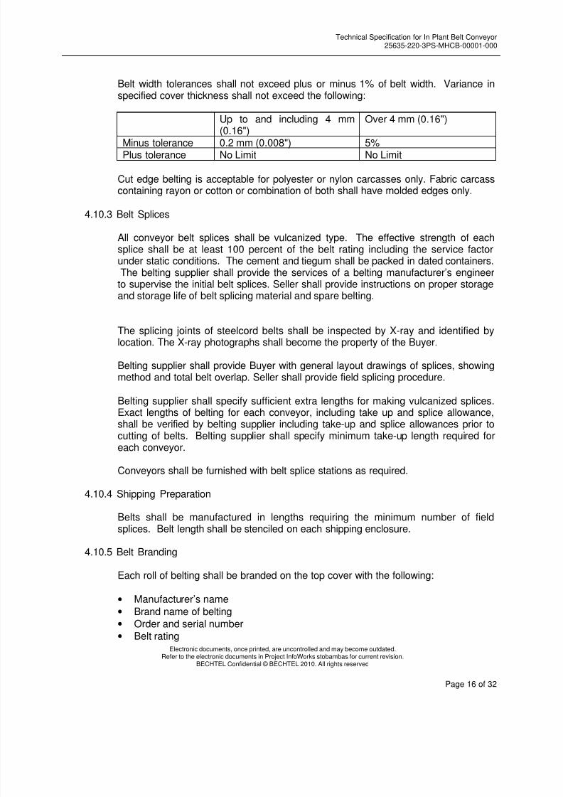
Belt width tolerances shall not exceed plus or minus 1% of belt width. Variance inspecified cover thickness shall not exceed the following:
Up to and including 4 mm(0.16")
Over 4 mm (0.16")
Minus tolerance 0.2 mm (0.008") 5% Plus tolerance No Limit No Limit
Cut edge belting is acceptable for polyester or nylon carcasses only. Fabric carcasscontaining rayon or cotton or combination of both shall have molded edges only.
4.10.3 Belt Splices
All conveyor belt splices shall be vulcanized type. The effective strength of eachsplice shall be at least 100 percent of the belt rating including the service factorunder static conditions. The cement and tiegum shall be packed in dated containers.The belting supplier shall provide the services of a belting manufacturer’s engineer
to supervise the initial belt splices. Seller shall provide instructions on proper storageand storage life of belt splicing material and spare belting.
The splicing joints of steelcord belts shall be inspected by X-ray and identified bylocation. The X-ray photographs shall become the property of the Buyer.
Belting supplier shall provide Buyer with general layout drawings of splices, showingmethod and total belt overlap. Seller shall provide field splicing procedure.
Belting supplier shall specify sufficient extra lengths for making vulcanized splices.Exact lengths of belting for each conveyor, including take up and splice allowance,shall be verified by belting supplier including take-up and splice allowances prior tocutting of belts. Belting supplier shall specify minimum take-up length required foreach conveyor.
Conveyors shall be furnished with belt splice stations as required.
4.10.4 Shipping Preparation
Belts shall be manufactured in lengths requiring the minimum number of fieldsplices. Belt length shall be stenciled on each shipping enclosure.
4.10.5 Belt Branding
Each roll of belting shall be branded on the top cover with the following:
• Manufacturer’s name
• Brand name of belting• Order and serial number• Belt rating
8/12/2019 02.34 25635-220-3PS-MHCB-00001 Technical.pdf
http://slidepdf.com/reader/full/0234-25635-220-3ps-mhcb-00001-technicalpdf 17/32
Technical Specification for In Plant Belt Conveyor25635-220-3PS-MHCB-00001-000
Electronic documents, once printed, are uncontrolled and may become outdated.Refer to the electronic documents in Project InfoWorks stobambas for current revision.
BECHTEL Confidential © BECHTEL 2010. All rights reserved
Page 17 of 32
• Belt weight per unit length
Example: GoodyearPlylon 440Mfg. Order No. 1234
Serial ABCDP.O. No. 1A1B dtd 5 May 9115 Kg per Meter
4.10.6 Testing
The manufacturer shall perform tests in accordance with ASTM D 378 and ASTM D2240, in order to demonstrate the following properties:
a. Belt: Ultimate strengthb. Fabric Belts: Elongationc. Carcass: Adhesion, ply to plyd. Cover: Tensile strength Adhesion, Cover Durometer
4.11 Access to Drives and Removability
Service platforms shall have a 1m minimum clearance around all equipment. Specialattention shall be given to the requirement that all mechanical equipment be readilyremovable without dismantling any structural steel framing.
4.12 Wind Hoods (When specified)
Belt hoods shall be provided by the Seller on all outdoor conveyors. Hinged typehoods shall be designed to enable complete and easy access for inspection andmaintenance for conveyors less than 1,800 mm wide. Three-quarter hood coversshall be furnished on conveyors 1,800 mm and wider. Hoods shall be reinforcedgalvanized steel sheet metal construction. The hoods shall be fastened on the top ofconveyor frame.
4.13 Guards
4.13.1 All guards including those for V-belt drives, couplings and exposed rotating shaftsshall be supplied in compliance with the OSHA and MSHA regulations. Non-lubricated drives shall have guards of flattened, expanded metal for visualinspection. All guards shall be fabricated and mounted with provision for rapid andeasy access to grease fittings. Grease fittings shall be located at points of easy andsafe access by the operator. Grease fittings shall be positioned such that they areaccessible without the need to open inspection doors or disconnect or dismantlesafety screens or guards. Plastic, PVC, or other buyer approved tubing material shallbe provided to connect all grease fittings to their respective bearings. Seller shallprovide guards at all nip-points on the conveyor.
4.13.2 Guards shall have sheet metal top and expanded metal (weighing not less than 2kg/m2 and openings shall not exceed 10 mm (3/8”)) sides. All guards shall be
8/12/2019 02.34 25635-220-3PS-MHCB-00001 Technical.pdf
http://slidepdf.com/reader/full/0234-25635-220-3ps-mhcb-00001-technicalpdf 18/32
Technical Specification for In Plant Belt Conveyor25635-220-3PS-MHCB-00001-000
Electronic documents, once printed, are uncontrolled and may become outdated.Refer to the electronic documents in Project InfoWorks stobambas for current revision.
BECHTEL Confidential © BECHTEL 2010. All rights reserved
Page 18 of 32
designed to allow lubrication of the equipment without the removal or opening of theguards.
4.14 Take- ups
4.14.1 Take-ups shall be designed with sufficient adjustment length to allow for a minimum
of two future splices.
4.14.2 Screw take-ups, where used, shall be protected screw type designed to operate intension, and shall be complete assemblies consisting of frame, screw adjustmentmechanism pillow blocks with roller bearings conforming to all requirements ofSection 4.8. The screw take-up travel shall be a minimum of 0.6 m and only forconveyor belt length up to 33 m.
4.14.3 Gravity take-ups shall include a counterweight box to be filled with steel balls or steelplate. Seller shall indicate required weight on counterweight box and design for 25%more volume for additional weight and 25% additional travel distance.
4.14.4 Overhead counterweights shall be avoided by the use of suspension cables. Safetyguards or fences shall be furnished by Seller to close off areas immediately underthe counterweight.
4.14.5 Counterweight safety cages shall be located at floor or grade level and shall bemade up of expanded metal weighing not less than 2 kg/m2 mounted on a structuralframe. Expanded metal panels shall be 2.2 m high and shall be set 450 mm aboveconcrete foundation or floor elevation.
4.14.6 Vertical gravity take-ups shall employ a dribble deflector canopy attached to pulleyframe to prevent debris from falling onto the take-up pulley.
4.14.7 Horizontal gravity take-ups carriages shall have V-grooved wheels and rails, and beself-cleaning (inverted angle). Hold downs shall be provided to prevent the wheelsfrom lifting off the rails. Counterweights shall be attached to the carriage frames bywire rope and sheaves.
4.14.8 Wire rope shall be flexible steel core hoisting rope with a minimum breaking strengthof six (6) times the maximum calculated working load. Rope ends shall be fastenedwith clips sufficient to develop the full breaking strength of the rope. Sheaves shallbe steel or cast steel with "lubrite" bushing or equal mounted on dead shafts.Sheave diameters shall be a minimum of 20 times the wire cable diameter.
4.15 Cleaners and Belt Washers
4.15.1 Except as noted below all belt conveyors shall be furnished with a dual belt scrapersystem to clean the carrying side of the belt at the head pulley. The scraper shall bea track mounted system as designed by Martin Engineering (or equal approved bybuyer). The width of the scraper shall be no less than the belt width plus 100 mm.

8/12/2019 02.34 25635-220-3PS-MHCB-00001 Technical.pdf
http://slidepdf.com/reader/full/0234-25635-220-3ps-mhcb-00001-technicalpdf 19/32
Technical Specification for In Plant Belt Conveyor25635-220-3PS-MHCB-00001-000
Electronic documents, once printed, are uncontrolled and may become outdated.Refer to the electronic documents in Project InfoWorks stobambas for current revision.
BECHTEL Confidential © BECHTEL 2010. All rights reserved
Page 19 of 32
4.15.2 Spring-loaded, "V"-type plows over the full belt width +100 mm minimum shall befurnished just clear of the return strand of belting and immediately ahead of all take-up and tail pulleys, where material can be caught between belt and pulley. The Vplow shall be mounted so that the steel framing cannot contact the belt after thewiper rubber has completely worn down. All plows shall be provided with a verticaladjustment and safety chain to prevent the plow from traveling with the belt in case
of failure of the mounting. Scraper rubber hardness shall be a durometer (Shore A)of 60-80. Minimum thickness of rubber blade shall be 13 mm.
4.16 Chutes and Skirtboards
4.16.1 Seller shall supply all chutes, skirtboards and skirtboard supports from conveyor toconveyor or from conveyor to the mating flange of Buyer's equipment unlessotherwise stated or as indicated on reference drawings. Buyer's equipment matingflange details will be given to the Seller at a later date.
4.16.2 General Construction
Skirtboards for the conveyors shall be fabricated from 10 mm (3/8 inch) minimumthick ASTM A 36 steel. Chute corners shall be made dust-tight by seal welds.Chutes shall be of welded construction with bolted flanges and shall be bolted totheir respective supporting frames. All chutes shall be provided with a minimum oftwo inspection doors, located on opposite sides of the chute. Where required formaintenance, additional doors and maintenance access shall be provided. Allconveyor chutes and other components shall be designed for easy maintenance.
All transfer chute designs shall be modeled precisely using Discrete ElementModeling (DEM) Software to validate the design. The model output shall besubmitted for approval.
All field and shop bolted connections shall be provided with gaskets, bolts, and lockwashers.
Rock boxes (except for copper concentrate) shall be provided for all chutes to breakthe horizontal and vertical velocity of flow and direct the material towards the centerof the belt between the skirtboards. V-throat bootjack design shall be used for alltransfer and loading points.
Minimum chute wall and valley angles shall be determined for the type of materialbeing conveyed with the selected chute lining material. Where material could buildup in valleys, the chute or the chute liners shall provide a radiused or chamferedvalley surface to reduce this.
Chutes at all discharges shall be designed to collect belt scrapings, and direct themonto the next belt in the system. Inside chute width at discharge pulleys shall bedesigned to be wide enough to contain the material stream plus an adequatedistance on each side that insures minimal wear. The minimum width shall be thebelt width plus 300 mm. Discharge chute entrance shall be provided with a dustcurtain.

8/12/2019 02.34 25635-220-3PS-MHCB-00001 Technical.pdf
http://slidepdf.com/reader/full/0234-25635-220-3ps-mhcb-00001-technicalpdf 20/32
Technical Specification for In Plant Belt Conveyor25635-220-3PS-MHCB-00001-000
Electronic documents, once printed, are uncontrolled and may become outdated.Refer to the electronic documents in Project InfoWorks stobambas for current revision.
BECHTEL Confidential © BECHTEL 2010. All rights reserved
Page 20 of 32
Chutes shall be designed to allow the installation and operation of ancillaryequipment or systems (Tramp magnets, dust colector systems, etc).
4.16.3 Chute Valley Angles
Minimum chute wall and valley angles shall be determined for the type of materialbeing conveyed with the selected chute lining material. Where material could buildup in valleys, the chute or the chute liners shall provide a radiused or chamferedvalley surface to reduce this.
All chute valley angles shall be a minimum of 65° from the horizontal.
All chutes shall be provided with cleanout and inspection doors with gasket, latchedand hinged (opening to the side).
4.16.4 Abrasion Resistant Lining
Abrasion resistant liners shall be provided for the conveyors and used on surfaceswhere material contacts the walls of chutes and skirtboards. Individual liners shall belimited to 30 kg maximum and shall be a minimum of 25 mm thick. The chute linerpatterns shall be standardized to minimize number of different sized pieces.
Abrasion resistant liners shall be :
- Ultra High Molecular Weight Polyethylene (for copper concentrate)- Steel 450-600 BHN (for copper ore)
In both cases shall be bolted with a minimum of three countersunk cap screws, withhex head nuts and lock washers.
4.16.5 Conveyor Skirtboards and Skirts
Skirtboards shall be designed to allow a smooth flow of material and shall be ofample depth. Skirtboard length shall be 2.5 m (minimum) for every 100 m/min. ofbelt speed or as otherwise indicated on drawings. Skirtboards shall be designed foreasy maintenance.
Commercially available, over center, clamp type fasteners shall be used to clampskirting rubber to the skirtboards.
Skirtboards shall be provided with 13 mm thick 40 durometer rubber sealing strips
manufactured by Corrosion Engineering (or equal approved by buyer).
Skirtboard covers shall be 4.8 mm (minimum) mild steel with suitable stiffeners.
Skirtboards for all conveyors shall also be provided with a cleanup hopper or hingedend cover on the tail end of the skirtboard to allow spilled material to be returned tothe conveyor.
8/12/2019 02.34 25635-220-3PS-MHCB-00001 Technical.pdf
http://slidepdf.com/reader/full/0234-25635-220-3ps-mhcb-00001-technicalpdf 21/32
Technical Specification for In Plant Belt Conveyor25635-220-3PS-MHCB-00001-000
Electronic documents, once printed, are uncontrolled and may become outdated.Refer to the electronic documents in Project InfoWorks stobambas for current revision.
BECHTEL Confidential © BECHTEL 2010. All rights reserved
Page 21 of 32
Skirtboard exits shall be provided with rubber dust curtains to contain the dust for allconveyors.
Seller shall include seals between chute and skirtboard.
4.17 Deck-Plates and Spill Barrier
All conveyors shall have decking between carrying and return belt as follows:
- at loading areas, from fixed tail pulley to 3 idler spaces past end of skirtboard- at gravity take-up, 3 idler spaces on either side of gravity take-up
Deck shall be a minimum of 4.0 mm thick steel with a crown.
Spill barriers shall be installed under the return belt at sections of conveyor overroadways and pedestrian crossing.
Barriers shall be a minimum of 4.0 mm thick steel with a trough.
4.18 Safety and Emergency Warning Devices
All conveyor safety devices and equipment instrumentation shall be standardizedconsistent with Buyer's overall plant instrumentation devices.
All control and alarm circuit contacts shall comply with Technical Specification forInstrument and Control supplied with Packaged Systems, document N° 25635-220-3PS-JQ07-00001.
4.18.1 Plugged Chute Detectors
The Seller shall furnish a microwave level switch type, having DPDT dry contactsrelay output. When discharge chute be supplied, the microwave barrier will belocated under head pulley (at five).
4.18.2 Belt Side Travel Switches
The Seller shall furnish belt side travel switches on each side of the conveyor belt.The switches shall be installed on all conveyors at head and tail pulleys. Each switchshall have DPDT contacts with independently adjustable alarm and shutdownpositions. Each conveyor shall be furnished with a minimum of 4 travel switches, twoat head end and two at tail end. The maximum spacing between two switches shall
not exceed 60 m. For variable speed conveyor, analog transmitter 4-20 mA outputwill be required.
4.18.3 Zero Speed Switch
The Seller shall furnish a proximity type zero speed switches on a non-drive pulley ofeach conveyor that has a minimum wrap angle of 180 °. Conveyor speed trip point
8/12/2019 02.34 25635-220-3PS-MHCB-00001 Technical.pdf
http://slidepdf.com/reader/full/0234-25635-220-3ps-mhcb-00001-technicalpdf 22/32
Technical Specification for In Plant Belt Conveyor25635-220-3PS-MHCB-00001-000
Electronic documents, once printed, are uncontrolled and may become outdated.Refer to the electronic documents in Project InfoWorks stobambas for current revision.
BECHTEL Confidential © BECHTEL 2010. All rights reserved
Page 22 of 32
of the switch shall be adjustable. A suitable adjustable time delay device shall beprovided as part of each zero speed switches to provide lock out of the "zero speedsignal" during conveyor startup and acceleration. The switch contacts shall beDPDT. For variable speed conveyor, analog transmitter 4-20 mA output will berequired.
4.18.4 Emergency Pullcord Switches
All conveyors shall be equipped with manually reset type emergency stoppingdevices. Protection shall extend for the full accessible length of the conveyor, up tothe guards on terminal pulleys. Pullcords shall be 4.8 mm galvanized steel cablecoated to 6.5 mm in diameter with safety yellow polyethylene cover and shall besupported on 3 m maximum spacing. The pullcords shall be located at least 300mm above the belt and also high enough such that material falling from the belt doesnot cause a nuisance trip. The pullcords shall be designed to be accessible to aperson standing on the walkway beside the conveyor. The allowable spacingbetween switches shall be 30 m maximum. Any section of conveyor which isaccessible from both sides shall be protected separately on both sides without
interconnection. The switch contacts shall be DPDT. Pullcord supports shall be the“pigtail” type.
The pull cord switch will have two contacts, one wired by direct current control to theMCC and the other as digital input to the Control System.
4.18.5 Warning Horns/Lights
The Seller shall furnish horns and lights to warn that a stationary belt is about to beset in motion. For belts longer than 100 m, additionals horns/light will be required inorder to all people along the belt be cautioned. Lights beacon shall be stroboscopictype.
4.18.6 Belt Rip
The Seller shall furnish a belt rip switch. The belt rip switch shall have SPDT drycontacts. One pair shall be supplied after each load material chute.
4.18.7 Mechanical Limit Switch
The Seller shall furnish a mechanical limit switch, for take up limit position. The limitswitch shall have SPDT dry contacts.
4.18.8 Pulley Temperature Detection
The Seller shall furnish a RTD temperature sensor (PT100, 3 wires) for bearing drivepulley temperature monitoring.
8/12/2019 02.34 25635-220-3PS-MHCB-00001 Technical.pdf
http://slidepdf.com/reader/full/0234-25635-220-3ps-mhcb-00001-technicalpdf 23/32
Technical Specification for In Plant Belt Conveyor25635-220-3PS-MHCB-00001-000
Electronic documents, once printed, are uncontrolled and may become outdated.Refer to the electronic documents in Project InfoWorks stobambas for current revision.
BECHTEL Confidential © BECHTEL 2010. All rights reserved
Page 23 of 32
4.19 Belt Scales
Belt scales, when required, shall be designed in accordance with the attached datasheet. Belt Scales shall be furnished with calibration weights.
4.20 Tramp Magnets
Where required, tramp magnets shall be supplied and installed according tomanufacturers’ specification. Magnets shall be mounted by adjustable hangings frommonorail trolleys that allow the magnets to be moved away from conveyors formaintenance or cleaning without disconnecting the power supply or removingtransfer chute components, unless provision is made in the transfer chute tofacilitate this.
Magnet installations shall take into account requirements for using non magneticsteels and other materials for pulleys, chutes and local structures to avoid themagnetizing effects of magnetic fields.
4.21 Metal Detector
Metal Detector, when required, shall be designed in accordance with the attacheddata sheet. Metal detectors shall be installed on conveyors as required, after anytramp magnet and before any transfer onto a long conveyor, at a sufficient distanceso metals can not reach the transfer area. Detectors shall be selected and located tofunction with the type of belt installed and be adjustable sensitivity. Also is requiredan accessible area for metals extraction, before transfer points.
Once activated the metal detector, the system shall activate a sprinkler that will paintthe charge of ore running through the belt.
4.22 Dust Enclousures
4.22.1 Dust enclosures shall be provided for housing dust suppression spray nozzles on thecrushed pebble conveyors.
4.22.2 The dust enclosure may consist of additional platework that will rest on theskirtboard. The receiving belt dust enclosure shall:
• Extend back toward the upstream side at least one belt width.
• Extend forward toward the downstream side at least three belt widths.
• Have a height above the lowest part of the belt of at least one belt width both
upstream and downstream
• Have continuous tight skirt boards on both sides for the entire length of thecover.

8/12/2019 02.34 25635-220-3PS-MHCB-00001 Technical.pdf
http://slidepdf.com/reader/full/0234-25635-220-3ps-mhcb-00001-technicalpdf 24/32
Technical Specification for In Plant Belt Conveyor25635-220-3PS-MHCB-00001-000
Electronic documents, once printed, are uncontrolled and may become outdated.Refer to the electronic documents in Project InfoWorks stobambas for current revision.
BECHTEL Confidential © BECHTEL 2010. All rights reserved
Page 24 of 32
4.23 Conveyor Steelwork and Structures
4.23.1 General
Conveyor steelframe, walkways, platforms, stairways, trusses and bents shall befurnished.
4.23.2 Design Requirements
Conveyor structural design shall be in accordance with Technical Specification forStructural Requirements for Mechanical Equipment, document N° 25635-220-3PS-S000-00001.
Foundation reactions and supporting calculations, including overall framing systemshall be provided for review and foundation design. This review does not relieve theSeller of full responsibility for the performance and integrity of the structures. Designcalculations shall be submitted for Buyer's record.
4.23.3 Loading Requirements
Conveyor Dead Loads (DL) shall include the calculated weights of all fixed elementsincluding electrical raceways and lighting.
Live Loads (LL), Wind Loads (WL) and Seismic Loads as per Technical Specificationfor Structural Requirements for Mechanical Equipment, document N° 25635-220-3PS-S000-00001.
Thermal Loads shall be based on atmospheric temperature range as indicated onthe Data Sheets. Provisions shall be made for stresses and movements resultingfrom variations in temperature.
Maximum Running Belt Tension Loads is that tension which can be developed by themotor nameplate horsepower, at full load speed, including motor service factor (butexcluding any torque limiting device).
Impact Loads shall be calculated in accordance with the requirements of the AISCManual of Steel Construction and the Technical Specification for StructuralRequirements for Mechanical Equipment, document N° 25635-220-3PS-S000-00001.
Loading combinations shall be as follows:
a) DL + LL + 1.5 x Maximum Running Belt Tension + Temp
b) DL + LL + 1.5 x Maximum Running Belt Tension + Temp + WL or Seismic,with allowable stresses increased 33%
c) DL + LL + Factor* x Maximum Running Belt Tension + Temp, with allowablestresses increased 33%

8/12/2019 02.34 25635-220-3PS-MHCB-00001 Technical.pdf
http://slidepdf.com/reader/full/0234-25635-220-3ps-mhcb-00001-technicalpdf 25/32
Technical Specification for In Plant Belt Conveyor25635-220-3PS-MHCB-00001-000
Electronic documents, once printed, are uncontrolled and may become outdated.Refer to the electronic documents in Project InfoWorks stobambas for current revision.
BECHTEL Confidential © BECHTEL 2010. All rights reserved
Page 25 of 32
d) DL + LL + Factor* x Maximum Running Belt Tension + Temp + WL orSeismic, with allowable stresses increased 50%
*Factor to be used in formula c) or d):
2.15 for DC motor2.25 for wound rotor motor1.8 for squirrel cage motor
Material Loads, which shall be included as live load, shall be as shown on theData Sheets. At transfer points, loads from plugged chutes filled to capacityshall be included.
e) DL + WL or Seismic (to check safety factor against overturning and uplift)
f) Others combinations as per Technical Specification for StructuralRequirements for Mechanical Equipment, document N° 25635-220-3PS-S000-
00001.
Of the above outlined loading combinations, the one that results in the higheststress for the structure or any element of the structure shall be used for thedesign.
g) Impact loads shall be as follows:
• Along the length of the conveyor, vertical impact force equivalent to 25% ofmaterial, belt and moving parts of idlers.
• At transfer points, vertical impact force due to falling material.
4.23.4 Construction
Fabrication shall be in accordance with the AISC "Specification for the Design,Fabrication and Erection of Structural Steel for Buildings."
All welding on the conveying system structure and equipment shall be in accordancewith the latest edition of the Structural Welding Code of the American WeldingSociety, AWS D1.1, or approved equal standard of quality.
Construction shall be shop welded and field bolted. Unless otherwise shown, fieldconnections shall be high strength bolts ASTM 325 in accordance with the AISC
"Specification for Structural Joints Using ASTM A325 or A490 Bolts”. Slip criticalbolts shall be used.
All shop welding shall be performed by welders who are qualified in accordance withAWS D1.1, latest revision. Performance qualification records of individual welderswill be reviewed at Seller's shop by the Buyer’s representative prior to fabrication.Performance qualification of each welder must be current.

8/12/2019 02.34 25635-220-3PS-MHCB-00001 Technical.pdf
http://slidepdf.com/reader/full/0234-25635-220-3ps-mhcb-00001-technicalpdf 26/32
Technical Specification for In Plant Belt Conveyor25635-220-3PS-MHCB-00001-000
Electronic documents, once printed, are uncontrolled and may become outdated.Refer to the electronic documents in Project InfoWorks stobambas for current revision.
BECHTEL Confidential © BECHTEL 2010. All rights reserved
Page 26 of 32
Conveyor frames shall be of steel toe-in stringer construction with suitable diagonaland cross bracing. Supports shall be of moment connected design to permit easycleaning. Diagonal bracing in the vicinity of floors, walkways or maintenance accessshall not be used.
Minimum vertical cleanup clearance at conveyor support bents and structures to be1 m on short bents and 1.5 m where possible.
4.24 Miscellaneous Requirements
Spillage Prevention and Cleanup
Seller shall incorporate in his design methods to minimize spillage and to direct suchspillage that may occur back onto the system or clear of operating machinery andbelt and into areas accessible for cleanup.
4.25 Calculations
Design calculations including structural connection calculations shall be submitted onall engineered equipment and structures. If a computer program or software is usedby the Seller, all input and output data shall be submitted as well as the basis of thecomputations.
All calculations shall be submitted for Buyer's review. The following is a list of theminimum type and number of calculations to be submitted.
a. Full tension analysis for the following conditions:
1. Normal running
2. Maximum loading/tension/torque3. Acceleration/deceleration4. Standstill tension
b. Power calculations for the following conditions:
1. Normal running2. Fully loaded3. Maximum power condition
c. Pulley and shaft sizing and bearing selection
d. Concave and convex curve calculations including belting selection
1. Curve analyses shall be performed for both carrying side and return sideof vertical curves and for all belt tension/power conditions listed above.
2. Concave vertical curve radii shall be sized to prevent lifting of the belt offthe idlers under any condition. The highest possible tension at the curve

8/12/2019 02.34 25635-220-3PS-MHCB-00001 Technical.pdf
http://slidepdf.com/reader/full/0234-25635-220-3ps-mhcb-00001-technicalpdf 27/32
Technical Specification for In Plant Belt Conveyor25635-220-3PS-MHCB-00001-000
Electronic documents, once printed, are uncontrolled and may become outdated.Refer to the electronic documents in Project InfoWorks stobambas for current revision.
BECHTEL Confidential © BECHTEL 2010. All rights reserved
Page 27 of 32
shall be computed (empty or full, winter or summer, reduced or fullfriction) and the empty belt weight shall be used to compute the requiredradius. The lowest possible tension at the curve shall be computed tomaintain the minimum edge tension for fabric belts shall be 30 PIW:
e. Take-up system calculations (travel, box size), elastic and permanent stretch.
f. Reducer, high and low speed coupling selection calculations.
g. All structural calculations on pulley frames, stringers, stringer hangers, posts,columns, bents and associated structures.
h. Torque vs. speed curves shall be prepared for each conveyor describing the loadparameters at the input shaft of the drive assembly for the conditions defined initem “b” above.
i. Idler selection and spacing
j. Seismic loading calculations
4.26 Electrical Requirements
4.26.1 All electrical components shall be in accordance with the Technical Specification forElectrical Equipment in Mechanical Packages N° 25635-220-3PS-EKP0-00001, Technical specification for NEMA Low Voltage AC Induction Motors N° 25635-220-3PS-MUMI-00001 and NEMA Medium Voltage AC Induction Motors N° 25635-220-3PS-MUMI-00002.
4.26.2 Mechanical equipment SELLER shall be responsible to: select and supply theelectric motor required for each application. Forward to BUYER the enclosed motor
Data Sheets, drawings, and documentation associated with the motor for BUYER'sreview. Instruct the motor Vendor to ship motor to SELLER's shop for assemblyand/or testing. Receive motor and verify technical and physical correctness, andassemble with mechanical equipment.
4.26.3 SELLER shall provide full details of electric power requirements for the equipmentspecified. Additionally, he shall identify the maximum and average powerrequirements, and estimated power demand per ton of product.
4.26.4 The enclosures for all electrical devices and terminal boxes shall be NEMA 4.
4.26.5 All equipment shall be furnished with grounding connection.
4.27 Instrumentation and Control Requirements
4.27.1 All instrumentation and controls shall be furnished in accordance with TechnicalSpecification for Instruments and Control Supplied with Packaged System N° 25635-220-3PS-JQ07-00001.
8/12/2019 02.34 25635-220-3PS-MHCB-00001 Technical.pdf
http://slidepdf.com/reader/full/0234-25635-220-3ps-mhcb-00001-technicalpdf 28/32
Technical Specification for In Plant Belt Conveyor25635-220-3PS-MHCB-00001-000
Electronic documents, once printed, are uncontrolled and may become outdated.Refer to the electronic documents in Project InfoWorks stobambas for current revision.
BECHTEL Confidential © BECHTEL 2010. All rights reserved
Page 28 of 32
4.27.2 SELLER shall furnish control descriptions, wiring diagrams, control schematics ofexternal circuits, device settings and ranges, for BUYER's use in detail design.
4.27.3 SELLER shall furnish or deliver all technical information for security devices, hookUPS, and calibration.
4.28 Structural Requirements
4.28.1 For seismic calculations, the International Building Code (IBC) shall apply.
4.28.2 The equipment and components shall be designed to withstand the seismic, windand snow loading without damage in normal operation as specified in TechnicalSpecification for Structural Requirements for Mechanical Equipment N° 25635-220-3PS-S000-00001, considering the seismic, wind and snow conditions per GeneralSite Conditions N° 25635-220-3PS-G000-00001.
4.28.3 SELLER shall furnish foundation loads in accordance with the same TechnicalSpecification for Structural Requirements for Mechanical Equipment, document No.
25635-220-3PS-S000-00001.
4.28.4 Walkways and platform shall be equipped with IBC 2006 handrails and toe platesconforming to appropriate OSHA or MSHA requirements, and according to theTechnical Specification for Structural Requirements for Mechanical Equipment No.25635-220-3PS-S000-00001.
4.28.5 SELLER is to provide design and anchor arrangement for the equipment, includingbolt quantity, location, type and diameter.
4.28.6 Vertical ladders are not acceptable as a primary means of access. Service platformsshall have a minimum width of 1 m, unless otherwise noted.
4.28.7 Handrails shall be 1.2 m high with two intermediate rails.
4.29 Environmental Requirements
4.29.1 Personnel noise exposure level shall conform to the requirements of OSHA 1910.95and the local regulations. In the event of conflict between the codes and the localregulations, the most stringent requirements shall apply.
4.29.2 The noise level from each item of equipment is preferred to not exceed maximumallowable sound pressure level (SPL) of 85 dB(A) at a distance of one meter.
5.0 WELDING
5.1 All steelwork shall be fabricated in accordance with the latest issue of the StructuralWelding Code of the American Welding Society, AWS D1.1 and in accordance withthe AISC Specification for Structural Steel Buildings (AISC 360-05) and Code ofStandard Practice for Steel Building and Bridges (AISC 303-05).

8/12/2019 02.34 25635-220-3PS-MHCB-00001 Technical.pdf
http://slidepdf.com/reader/full/0234-25635-220-3ps-mhcb-00001-technicalpdf 29/32
Technical Specification for In Plant Belt Conveyor25635-220-3PS-MHCB-00001-000
Electronic documents, once printed, are uncontrolled and may become outdated.Refer to the electronic documents in Project InfoWorks stobambas for current revision.
BECHTEL Confidential © BECHTEL 2010. All rights reserved
Page 29 of 32
5.2 Structural drawings shall show welds requiring non-destructive tests, the extent ofeach type of test for each weld, the method of testing and the standards ofacceptance.
5.3 All welding shall be performed at the SELLER's shop, except as indicated in Section8.5.
5.4 All welding shall be as specified by AWS D1.1 Sections 2, 3, 4, and 5.Nondestructive examination shall be in accordance with the latest edition of AWSD1.1 with acceptance levels as indicated for Dynamically Loaded Structures Section6.0. All pulley welds shall be visually examined and shall be tested in their entirety,by ultrasonic or radiography, and by the magnetic particle method.
5.5 All welding procedures shall be in accordance with AWS D1.1, Sections 5.1 and 5.2.Welding and nondestructive examination procedures shall be submitted to and
reviewed by the Buyer prior to production. Welder qualification records shall bereviewed by the Buyer's field inspection personnel.
5.6 Pulleys shall be stress relieved after completion of all welding and before machining.
6.0 PAINTING
6.1 Unless otherwise specified in the equipment specifications or data sheets, allexposed metal surfaces except for machined surfaces shall be prepared, primed andfinish painted according to the “Technical Specification for Shop Priming andPainting” No. 25635-220-3PS-NX00-00001, Class A-3 or according toManufacturer’s standard procedures suitable for the intended service conditions,previously approved by BUYER.
6.2 Mechanical, electrical and instrumentation components shall be shop prime and
finish painted in accordance with the manufacturer's standard procedures.
6.3 Handrails, walkways, ladders, and equipment safety guards shall be painted highvisibility yellow.
7.0 QUALITY ASSURANCE, ASSEMBLY, INSPECTION AND TESTING
General
7.1 SELLER shall advise BUYER as to the quality control procedures and/or testingprogram followed to guarantee soundness and integrity of castings, forgings, andother materials used in this equipment.
7.2 All equipment and assembly, including Control Panels shall be completely shopassembled, skid mounted and operationally shop tested. Acceptance criteria bySELLER. A record of tests performed, including tests required for compliance withspecifications and correct fit-up.
8/12/2019 02.34 25635-220-3PS-MHCB-00001 Technical.pdf
http://slidepdf.com/reader/full/0234-25635-220-3ps-mhcb-00001-technicalpdf 30/32
Technical Specification for In Plant Belt Conveyor25635-220-3PS-MHCB-00001-000
Electronic documents, once printed, are uncontrolled and may become outdated.Refer to the electronic documents in Project InfoWorks stobambas for current revision.
BECHTEL Confidential © BECHTEL 2010. All rights reserved
Page 30 of 32
Functional and Operational Test
7.3 Non destructive tests scope and technique applied will be as per SELLER’sstandard.
7.4 All magnetic particle examinations shall be performed in accordance with the true
continuous magnetizing technique in accordance with ASTM E-709. Acceptancecriteria will be as per SELLER.
7.5 A record of tests performed, including tests required for compliance with regulatoryor industry codes, shall be submitted to BUYER. SELLER shall retain originals of alltest reports throughout the equipment warranty period.
7.6 Witness and Hold points shall be according to Section 5 - Supplier QualitySurveillance Plan, in the Material Requisition.
7.7 The supply shall include an integration test for the Overland Conveyor controlsystem, which will be performed in the Electrical Equipments supplier installations
with the control system interconnected with the remote I/O panels, operatorworkstation and electrical equipments. The test shall include:
1. Communications Test, to show that all components communicate correctly toeach other.
2. Functionality Test, to show that the control functionality has been correctlyprogrammed, configured and implemented by the Vendor as described in theMaterial Requisition and pertinent Technical Specifications.
7.8 For test purposes, the field signals will be simulated. The Vendor shall issue forapproval an integration test protocol, including proposed test setup and test
descriptions, eight weeks in advance of the scheduled FAT date, and immediatelyupon finishing the Test shall deliver a integration test Report.
Assembly
7.9 Upon completion of shop test the SELLER shall be dismantled the equipment only tothe extent necessary for packing and shipping. All components shall be match-marked to facilitate field assembly. The match marks shall be stamped not painted,in conspicuous locations where they will not be obliterated prior to assembly.
7.10 Fabricated steel components shall be shop-assembled and checked for fit anddimensional accuracy, and shall be match-marked prior to disassembly for shipment.
7.11 Conveyor stringers and idlers shall be shipped assembled to the maximum practicalextent, with lifting points clearly marked.
7.12 Drive systems consisting completely of motor, gear reducer, complete pulleyassemblies shall be assembled in shop on their own base and operated with no load,and shipped as large an assembly as practicable, after confirmation with assembly

8/12/2019 02.34 25635-220-3PS-MHCB-00001 Technical.pdf
http://slidepdf.com/reader/full/0234-25635-220-3ps-mhcb-00001-technicalpdf 31/32
Technical Specification for In Plant Belt Conveyor25635-220-3PS-MHCB-00001-000
Electronic documents, once printed, are uncontrolled and may become outdated.Refer to the electronic documents in Project InfoWorks stobambas for current revision.
BECHTEL Confidential © BECHTEL 2010. All rights reserved
Page 31 of 32
assembly drawings. Non drive pulley systems shall be fully assembled andconfirmed per assembly drawings and shipped as large as assembly as practicable.
Quality Assurance
7.13 SELLER shall furnish details of the quality assurance program to be applied during
the preparation of fabrication of equipment. Program shall describe the measures tobe used to control activities affecting the quality of equipment to be supplied incompliance with this Specification. SELLER quality assurance program shall bebased on ISO 9001:2008 requirements or BUYER approved equivalent.
7.14 Written certification shall be furnished by the SELLER that the equipment has beenmanufactured in compliance with the quality assurance program and requirement ofthe procurement documents. This certification will be the basis of Purchaser’s finalpayment of Purchase Order.
7.15 The equipment components shall be completely shop assembled, inspected andtested in accordance with ISO 9001:2008 requirements or BUYER approved
equivalent, prior to shipment to check for correct fit up and for compliance withSpecification requirements. BUYER reserves the option to inspect the equipment inSELLER’s shop and to witness tests. All critical dimensions shall be verified an allmotions shall be tested, without load, using crusher’s own controls and wiring, priorto shipment. All locking and safety devices shall be tested for their intendedfunctions. All motors and controls shall be operated at the specified voltage.
8.0 ASSEMBLY AND SHIPMENT
8.1 All critical dimensions shall be verified and all moving parts tested prior to shipment.
8.2 All equipment shall be shipped in accordance to Section 7 of the Material
Requisition, “Shipping Terms”, is exceeded, each equipment and ancillary must bedivided in the largest sections possible, in order to comply with shipping limitationsand facilitate assembly at field.
8.3 Upon satisfactory performance, the equipment shall be dismantled only to the extentnecessary for packing and shipping. All components shall be match-marked tofacilitate field assembly. The match marks shall be stamped not painted, inconspicuous locations where they will not be obliterated prior to assembly. Machinedsurfaces shall be suitably protected for shipment.
8.4 Steel tags shall be attached firmly by stainless steel wire or screws to each main partitem / component or instrument shipped loose from main equipment.
8.5 Large components that have to be shipped in smaller size pieces, due to shippingdimensional limits, may be welded at site. Equipment shall be modularized orassembled to a maximum extent to minimize field labor and these pieces shallconsider bolted connections to locate the pieces at the correct position for welding.In this case, approval by BUYER will be required.

8/12/2019 02.34 25635-220-3PS-MHCB-00001 Technical.pdf
http://slidepdf.com/reader/full/0234-25635-220-3ps-mhcb-00001-technicalpdf 32/32
Technical Specification for In Plant Belt Conveyor25635-220-3PS-MHCB-00001-000
Electronic documents, once printed, are uncontrolled and may become outdated.R f h l i d i P j I f W k b b f i i
8.6 The SELLER also shall confirm correct fit for all components and the entiresatisfaction of the BUYER prior to shipment.
8.7 All exposed machined surfaces shall be coated with an approved corrosion inhibitorcompound and protected against damage.
8.8 All equipment shall be shop assembled to the maximum extent practicable to verifyproper fit. Where complete shop assembly is not possible, templates or any othermeans acceptable to both the BUYER and SELLER shall be used to verify proper fitof mating components.
8.9 Such shipping assemblies shall have clearly marked lifting points, weights andindication of center gravity for safe handling during shipment and installation.