Embed Size (px)
Citation preview
Introduction 4
Congratulations 4Safety and environment protection 5Symbol glossary 8
Instrument Cluster 10
Warning and control lights 10Gauges 17
Entertainment Systems 19
AM/FM stereo cassette 19AM/FM stereo cassette (CD changer compatible) 26CD changer 38
Climate Controls 43
Electronic automatic temperature control 43
Lights 49
Headlamps 49Bulb replacement 53
Driver Controls 59
Steering wheel adjustment 60Power windows 62Mirrors 63Message center 77
Locks and Security 88
Keys 88Locks 88Anti-theft system 90
Table of Contents
1

Seating and Safety Restraints 102
Seating 102Safety restraints 106Air bags 121Child restraints 128
Driving 136
Starting 136Brakes 140Traction control/AdvanceTrac 143Transmission operation 146Vehicle loading 150Trailer towing 151Recreational towing 154
Roadside Emergencies 156
Hazard flasher switch 157Fuses and relays 158Changing tires 165Jump starting 169Wrecker towing 175
Customer Assistance 176
The dispute settlement board 179Utilizing the mediation/arbitration 182Getting assistance outside the U.S. and Canada 182Ordering additional owner’s literature 183Reporting safety defects (U.S. only) 185
Cleaning 186
Cleaning your vehicle 186Underbody preservation 191
Table of Contents
2
Maintenance and Specifications 193
Hood 194Engine compartment 194Engine oil 195Battery 199Fuel information 207Air filter(s) 221Refill capacities 227Lubricant specifications 228Engine data 230Vehicle dimensions 230
Accessories 234
Index 237
All rights reserved. Reproduction by any means, electronic or mechanicalincluding photocopying, recording or by any information storage and retrievalsystem or translation in whole or part is not permitted without writtenauthorization from Ford Motor Company. Ford may change the contents withoutnotice and without incurring obligation.
Copyright © 2001 Ford Motor Company
Table of Contents
3

The following warning may be required by California law:
CALIFORNIA Proposition 65 Warning
WARNING: Engine exhaust, some of its constituents, andcertain vehicle components contain or emit chemicals known to
the State of California to cause cancer and birth defects or otherreproductive harm. In addition, certain fluids contained in vehicles andcertain products of component wear contain or emit chemicals knownto the State of California to cause cancer and birth defects or otherreproductive harm.
CONGRATULATIONSCongratulations on acquiring your new Lincoln. Please take the time toget well acquainted with your vehicle by reading this handbook. Themore you know and understand about your vehicle the greater the safetyand pleasure you will derive from driving it.
For more information on Ford Motor Company and its products visit thefollowing website:
In the United States: www.ford.com
In Canada: www.ford.ca
In Mexico: www.ford.com.mx
In Australia: www.ford.com.au
Additional owner information is given in separate publications.
This Owner’s Guide describes every option and model variantavailable and therefore some of the items covered may not apply
to your particular vehicle. Furthermore, due to printing cycles it maydescribe options before they are generally available.
Remember to pass on the Owner’s Guide when reselling thevehicle. It is an integral part of the vehicle.
Introduction
4

Fuel pump shut-off switch In the event of an accident thesafety switch will automatically cut off the fuel supply to the
engine. The switch can also be activated through sudden vibration (e.g.collision when parking). To reset the switch, refer to the Fuel pumpshut-off switch in the Roadside emergencies chapter.
SAFETY AND ENVIRONMENT PROTECTION
Warning symbols in this guideHow can you reduce the risk of personal injury and prevent possibledamage to others, your vehicle and its equipment? In this guide, answersto such questions are contained in comments highlighted by the warningtriangle symbol. These comments should be read and observed.
Warning symbols on your vehicleWhen you see this symbol, it isimperative that you consult therelevant section of this guide beforetouching or attempting adjustmentof any kind.
Protecting the environmentWe must all play our part inprotecting the environment. Correctvehicle usage and the authorizeddisposal of waste cleaning andlubrication materials are significantsteps towards this aim. Information in this respect is highlighted in thisguide with the tree symbol.
Introduction
5
BREAKING-IN YOUR VEHICLEThere are no particular guidelines for breaking-in your vehicle. Duringthe first 1 600 km (1 000 miles) of driving, vary speeds frequently. This isrecommended to give the moving parts a chance to break in.
SPECIAL NOTICES
Emission warrantyThe New Vehicle Limited Warranty includes Bumper-to-BumperCoverage, Safety Restraint Coverage, Corrosion Coverage, and 7.3LPower Stroke Diesel Engine Coverage. In addition, your vehicle is eligiblefor Emissions Defect and Emissions Performance Warranties. For adetailed description of what is covered and what is not covered, refer tothe Warranty Guide that is provided to you along with your Owner’sGuide.
Special instructionsFor your safety, your vehicle is fitted with sophisticated electroniccontrols.
By operating other electronic equipment (e.g. mobile telephonewithout exterior aerial) electromagnetic fields can occur which
can cause malfunctions of the vehicle electronics. Therefore you shouldobserve the instructions of the equipment manufacturers.
Please read the section Air bag in the Seating and safetyrestraints chapter. Failure to follow the specific warnings and
instructions could result in personal injury.
Rear facing child or baby seats should NEVER be used in frontof a passenger side air bag.
Introduction
6
MIDDLE EAST/NORTH AFRICA VEHICLE SPECIFIC INFORMATIONFor your particular global region, your vehicle may be equipped withfeatures and options that are different from the ones that are describedin this Owner Guide; therefore, a supplement has been supplied thatcomplements this book. By referring to the pages in the providedsupplement, you can properly identify those features, recommendationsand specifications that are unique to your vehicle. Refer to this OwnerGuide for all other required information and warnings.
Introduction
7
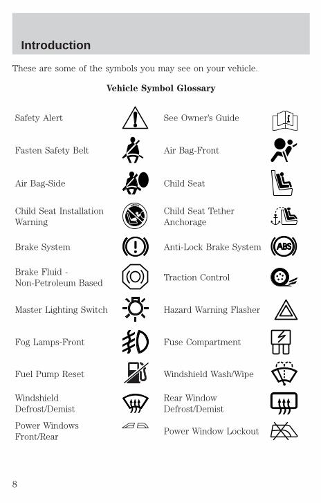
These are some of the symbols you may see on your vehicle.
Vehicle Symbol Glossary
Safety Alert See Owner’s Guide
Fasten Safety Belt Air Bag-Front
Air Bag-Side Child Seat
Child Seat InstallationWarning
Child Seat TetherAnchorage
Brake System Anti-Lock Brake System
Brake Fluid -Non-Petroleum Based
Traction Control
Master Lighting Switch Hazard Warning Flasher
Fog Lamps-Front Fuse Compartment
Fuel Pump Reset Windshield Wash/Wipe
WindshieldDefrost/Demist
Rear WindowDefrost/Demist
Power WindowsFront/Rear
Power Window Lockout
Introduction
8

Vehicle Symbol Glossary
Child Safety DoorLock/Unlock
Interior LuggageCompartment ReleaseSymbol
Panic Alarm Engine Oil
Engine CoolantEngine CoolantTemperature
Do Not Open When Hot Battery
Avoid Smoking, Flames,or Sparks
Battery Acid
Explosive Gas Fan Warning
Power Steering FluidMaintain Correct FluidLevel
MAX
MIN
Emission System Engine Air Filter
Passenger CompartmentAir Filter
Jack
Check fuel cap Low tire warning
Introduction
9
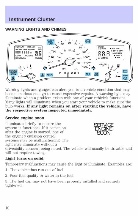
WARNING LIGHTS AND CHIMES
Warning lights and gauges can alert you to a vehicle condition that maybecome serious enough to cause expensive repairs. A warning light mayilluminate when a problem exists with one of your vehicle’s functions.Many lights will illuminate when you start your vehicle to make sure thebulb works. If any light remains on after starting the vehicle, havethe respective system inspected immediately.
Service engine soonIlluminates briefly to ensure thesystem is functional. If it comes onafter the engine is started, one ofthe engine’s emission controlsystems may be malfunctioning. Thelight may illuminate without adriveability concern being noted. The vehicle will usually be drivable andwill not require towing.
Light turns on solid:
Temporary malfunctions may cause the light to illuminate. Examples are:
1. The vehicle has run out of fuel.
2. Poor fuel quality or water in the fuel.
3. The fuel cap may not have been properly installed and securelytightened.
10
20
30
4050
60 70
80
90
100
120
20
60
80
40
100120
160
140
180
P R N D 2 1
MPH km/h
110
H F
E
1 2
FILL ONLEFT
<
AIRBAG
CHECKFUELCAP
SERVICEENGINESOON
TRUNK AJAR DOOR AJARTRAC OFF AIR SUSPENSION
O/D OFF TRAC ACTIVESPEED CONTROL COMPASS
km
CIRCLE SLOWLY
FUEL ECON DIST TO EMPTY
AVG SPEEDTRIP A B
E/Mkm MILES/GAL
WASHER LTR/100km
BRAKE
SERVICEENGINESOON
Instrument Cluster
10
These temporary malfunctions can be corrected by filling the fuel tankwith high quality fuel of the recommended octane and/or properlyinstalling and securely tightening the fuel cap. After three driving cycleswithout these or any other temporary malfunctions present, the lightshould turn off. (A driving cycle consists of a cold engine startupfollowed by mixed city/highway driving.) No additional vehicle service isrequired.
If the light remains on, have your vehicle serviced at the first availableopportunity.
Light is blinking:
Engine misfire is occurring which could damage your catalytic converter.You should drive in a moderate fashion (avoid heavy acceleration anddeceleration) and have your vehicle serviced at the first availableopportunity.
Under engine misfire conditions, excessive exhaust temperaturescould damage the catalytic converter, the fuel system, interior
floor coverings or other vehicle components, possibly causing a fire.
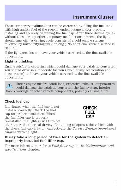
Check fuel capIlluminates when the fuel cap is notinstalled correctly. Check the fuelcap for proper installation. Whenthe fuel filler cap is properlyre-installed, the light(s) will turn offafter a period of normal driving. Continuing to operate the vehicle withthe check fuel cap light on, can activate the Service Engine Soon/CheckEngine warning light.
It may take a long period of time for the system to detect animproperly installed fuel filler cap.
For more information, refer to Fuel filler cap in the Maintenance andspecifications chapter.
CHECKFUELCAP
Instrument Cluster
11

Brake system warningIlluminates if the parking brake isengaged. Also momentarilyilluminates at start up to ensure thecircuit is functional. If the brakewarning lamp does not illuminate atthese times, or illuminates after releasing the parking brake, seek serviceimmediately. Refer to Brakes in the Driving chapter for moreinformation.
Anti-lock brake system (ABS)Momentarily illuminates at start upto ensure the circuit is functional. Ifthe light does not illuminate,remains on or continues to flash, theABS needs to be serviced (refer toBrakes in the Driving chapter for more information). With the ABS lighton, the ABS is disabled and normal braking is still functional.
Air bag readinessIlluminates to confirm that the airbags (front or side) are operational.If the light fails to illuminate,continues to flash or remains on,have the system serviced immediately.
Safety beltIlluminates to remind you to fastenyour safety belts. For moreinformation, refer to the Seatingand safety restraints chapter.
Charging systemIlluminates when the battery is notcharging properly.
!BRAKE
ABS
AIRBAG
Instrument Cluster
12
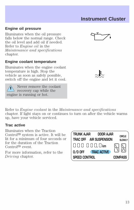
Engine oil pressureIlluminates when the oil pressurefalls below the normal range. Checkthe oil level and add oil if needed.Refer to Engine oil in theMaintenance and specificationschapter.
Engine coolant temperatureIlluminates when the engine coolanttemperature is high. Stop thevehicle as soon as safely possible,switch off the engine and let it cool.
Never remove the coolantrecovery cap while the
engine is running or hot.
Refer to Engine coolant in the Maintenance and specificationschapter. If light stays on or continues to turn on after the vehicle warmsup, have your vehicle serviced.
Trac activeIlluminates when the TractionControly system is active. It will belit for a minimum of four seconds orfor the duration of the TractionControly event.
For more information, refer to theDriving chapter.
TRUNK AJAR DOOR AJARTRAC OFF AIR SUSPENSION
O/D OFF TRAC ACTIVESPEED CONTROL COMPASS
km
CIRCLE SLOWLY
Instrument Cluster
13
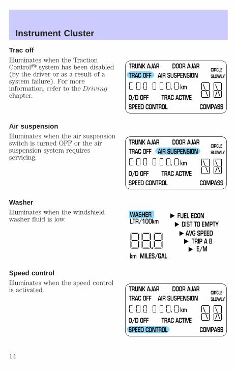
Trac offIlluminates when the TractionControly system has been disabled(by the driver or as a result of asystem failure). For moreinformation, refer to the Drivingchapter.
Air suspensionIlluminates when the air suspensionswitch is turned OFF or the airsuspension system requiresservicing.
WasherIlluminates when the windshieldwasher fluid is low.
Speed controlIlluminates when the speed controlis activated.
TRUNK AJAR DOOR AJARTRAC OFF AIR SUSPENSION
O/D OFF TRAC ACTIVESPEED CONTROL COMPASS
km
CIRCLE SLOWLY
TRUNK AJAR DOOR AJARTRAC OFF AIR SUSPENSION
O/D OFF TRAC ACTIVESPEED CONTROL COMPASS
km
CIRCLE SLOWLY
FUEL ECON DIST TO EMPTY
AVG SPEEDTRIP A B
E/Mkm MILES/GAL
WASHER LTR/100km
TRUNK AJAR DOOR AJARTRAC OFF AIR SUSPENSION
O/D OFF TRAC ACTIVESPEED CONTROL COMPASS
km
CIRCLE SLOWLY
Instrument Cluster
14

O/D offIlluminates when the overdrivefunction has been turned OFF usingthe Transmission Control Switch(TCS). If the light does not come onor the light flashes steadily, haveyour vehicle serviced as soon aspossible, damage to the transmissioncould occur.
Turn signalsIlluminates when the turn signals orthe hazard lights are turned on. Ifthe lights stay on continuously orflash faster, check for a burned-outbulb.
High beamsIlluminates when the high beamheadlamps are turned on.
Door ajarIlluminates when any door is open(or not fully closed).
TRUNK AJAR DOOR AJARTRAC OFF AIR SUSPENSION
O/D OFF TRAC ACTIVESPEED CONTROL COMPASS
km
CIRCLE SLOWLY
TRUNK AJAR DOOR AJARTRAC OFF AIR SUSPENSION
O/D OFF TRAC ACTIVESPEED CONTROL COMPASS
km
CIRCLE SLOWLY
Instrument Cluster
15
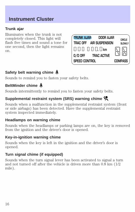
Trunk ajarIlluminates when the trunk is notcompletely closed. This light willflash five times and sound a tone forone second, then the light remainson.
Safety belt warning chimeSounds to remind you to fasten your safety belts.
BeltMinder chimeSounds intermittently to remind you to fasten your safety belts.
Supplemental restraint system (SRS) warning chimeSounds when a malfunction in the supplemental restraint system (frontor side airbags) has been detected. Have the supplemental restraintsystem inspected immediately.
Headlamps on warning chimeSounds when the headlamps or parking lamps are on, the key is removedfrom the ignition and the driver’s door is opened.
Key-in-ignition warning chimeSounds when the key is left in the ignition and the driver’s door isopened.
Turn signal chime (if equipped)Sounds when the turn signal lever has been activated to signal a turnand not turned off after the vehicle is driven more than 0.8 km (1/2mile).
TRUNK AJAR DOOR AJARTRAC OFF AIR SUSPENSION
O/D OFF TRAC ACTIVESPEED CONTROL COMPASS
km
CIRCLE SLOWLY
Instrument Cluster
16
GAUGES
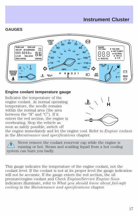
Engine coolant temperature gaugeIndicates the temperature of theengine coolant. At normal operatingtemperature, the needle remainswithin the normal area (the areabetween the “H” and “C”). If itenters the red section, the engine isoverheating. Stop the vehicle assoon as safely possible, switch offthe engine immediately and let the engine cool. Refer to Engine coolantin the Maintenance and specifications chapter.
Never remove the coolant reservoir cap while the engine isrunning or hot. Steam and scalding liquid from a hot cooling
system can burn you badly.
This gauge indicates the temperature of the engine coolant, not thecoolant level. If the coolant is not at its proper level the gauge indicationwill not be accurate. If the gauge enters the red section, the oilpressure/engine coolant and Check Engine/Service Engine Soonindicators illuminate, refer to What you should know about fail-safecooling in the Maintenance and specifications chapter.
10
20
30
4050
60 70
80
90
100
120
20
60
80
40
100120
160
140
180
P R N D 2 1
MPH km/h
110
H F
E
1 2
FILL ONLEFT
<
AIRBAG
CHECKFUELCAP
SERVICEENGINESOON
TRUNK AJAR DOOR AJARTRAC OFF AIR SUSPENSION
O/D OFF TRAC ACTIVESPEED CONTROL COMPASS
km
CIRCLE SLOWLY
FUEL ECON DIST TO EMPTY
AVG SPEEDTRIP A B
E/Mkm MILES/GAL
WASHER LTR/100km
BRAKE
H
Instrument Cluster
17

Fuel gaugeDisplays approximately how muchfuel is in the fuel tank. The fuelgauge may vary slightly when thevehicle is in motion or on a grade.
When refueling the vehicle fromempty indication, the amount of fuelthat can be added will be less thanthe advertised capacity due to thereserve fuel.
SpeedometerIndicates the current vehicle speed.
OdometerRegisters the total kilometers(miles) of the vehicle.
F
E
1 2
FILL ONLEFT
<
10
20
30
4050
60 70
80
90
100
120
20
60
80
40
100120
160
140
180
MPH km/h
110
TRUNK AJAR DOOR AJARTRAC OFF AIR SUSPENSION
O/D OFF TRAC ACTIVESPEED CONTROL COMPASS
km
CIRCLE SLOWLY
Instrument Cluster
18
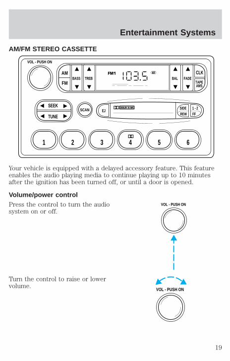
AM/FM STEREO CASSETTE
Your vehicle is equipped with a delayed accessory feature. This featureenables the audio playing media to continue playing up to 10 minutesafter the ignition has been turned off, or until a door is opened.
Volume/power controlPress the control to turn the audiosystem on or off.
Turn the control to raise or lowervolume.
SCAN
BASS TREB BAL FADE
SIDEEJ
REW FF1 - 2
TAPEAMS
VOL - PUSH ON
SEEK
TUNE
AM
FM
CLK
1 2 3 4 5 6
FM1 ST
VOL - PUSH ON
VOL - PUSH ON
Entertainment Systems
19

If the volume is set above a certain level and the ignition is turned off,the volume will come back on at a “nominal” listening level when theignition switch is turned back on.
Bass adjustThe bass adjust control allows youto increase or decrease the audiosystem’s bass output.
Treble adjustThe treble adjust control allows youto increase or decrease the audiosystem’s treble output.
Speaker balance adjustSpeaker sound distribution can beadjusted between the right and leftspeakers.
BASS
TREB
BAL
Entertainment Systems
20
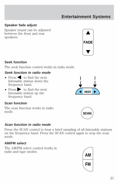
Speaker fade adjustSpeaker sound can be adjustedbetween the front and rearspeakers.
Seek functionThe seek function control works in radio mode.
Seek function in radio mode• Press to find the next
listenable station down thefrequency band.
• Press to find the nextlistenable station up thefrequency band.
Scan functionThe scan function works in radiomode.
Scan function in radio modePress the SCAN control to hear a brief sampling of all listenable stationson the frequency band. Press the SCAN control again to stop the scanmode.
AM/FM selectThe AM/FM select control works inradio and tape modes.
FADE
SCAN
AM
FM
Entertainment Systems
21
AM/FM select in radio modeThis control allows you to select AM or FM frequency bands. Press theAM control to select from AM selections, and press the FM control toselect from FM1 or FM2 memory preset stations.
AM/FM select in tape modePress this control to stop tape play and begin radio play.
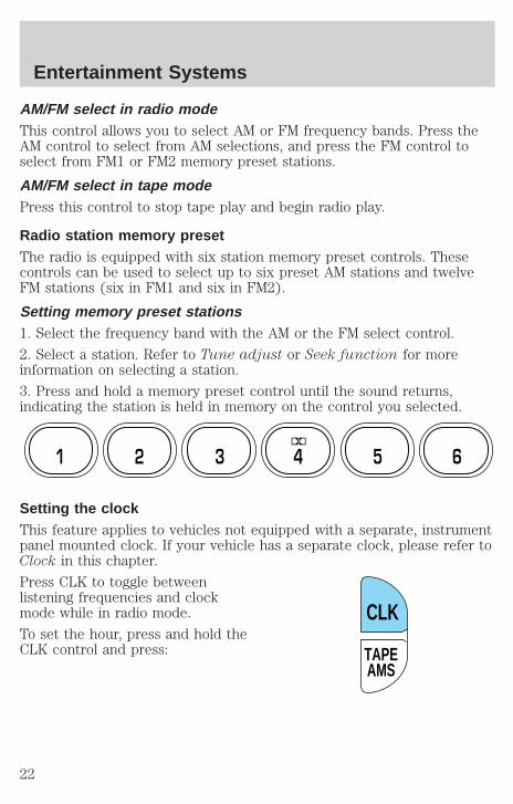
Radio station memory presetThe radio is equipped with six station memory preset controls. Thesecontrols can be used to select up to six preset AM stations and twelveFM stations (six in FM1 and six in FM2).
Setting memory preset stations1. Select the frequency band with the AM or the FM select control.
2. Select a station. Refer to Tune adjust or Seek function for moreinformation on selecting a station.
3. Press and hold a memory preset control until the sound returns,indicating the station is held in memory on the control you selected.
Setting the clockThis feature applies to vehicles not equipped with a separate, instrumentpanel mounted clock. If your vehicle has a separate clock, please refer toClock in this chapter.
Press CLK to toggle betweenlistening frequencies and clockmode while in radio mode.
To set the hour, press and hold theCLK control and press:
1 2 3 4 5 6
TAPEAMS
CLK
Entertainment Systems
22

• to decrease hours and
• to increase hours.
To set the minute, press and holdthe CLK control and press:
• to decrease minutes and
• to increase minutes.
The CLK control will allow you to switch between media display mode(radio station, stereo information, etc.) and clock display mode (time).When in clock mode, the media information will display for 10 seconds,when the radio is turned on, and then revert to clock information. Anytime that the media is changed, (new radio station, etc.), the mediainformation will again display for 10 seconds before reverting back to theclock. In media mode, the media information will always be displayed.
Tune adjustThe tune control works in radio mode.
Tune adjust in radio mode• Press to move to the next
frequency down the band(whether or not a listenablestation is located there). Hold thecontrol to move through thefrequencies quickly.
• Press to move to the nextfrequency up the band (whether or not a listenable station is locatedthere). Hold for quick movement.
TAPEAMS
CLK
Entertainment Systems
23

Tape select• To enter tape mode while in radio
mode, press the TAPE AMScontrol.
Automatic Music SearchThe Automatic Music Search featureallows you to quickly locate thebeginning of the tape selectionbeing played or to skip to the nextselection.
To activate the feature, momentarilydepress the TAPE AMS button.Then, press either REW (for thebeginning of the current selection) or FF (to advance to the nextselection). The tape deck stops and returns to play mode when the AMScircuit senses a blank section on the tape.
In order to ensure proper operation of the AMS feature, the tape MUSThave a blank section of at least four seconds duration between programs.
RewindThe rewind control works in tapemode.
To rewind in tape mode, press theREW control.
Fast forwardThe fast forward control works intape mode.
To fast forward in tape mode, pressthe FF control.
In the tape mode, tape direction will automatically reverse when the endof the tape is reached.
TAPEAMS
CLK
TAPEAMS
CLK
SIDEREW FF
1 - 2
SIDEREW FF
1 - 2
Entertainment Systems
24
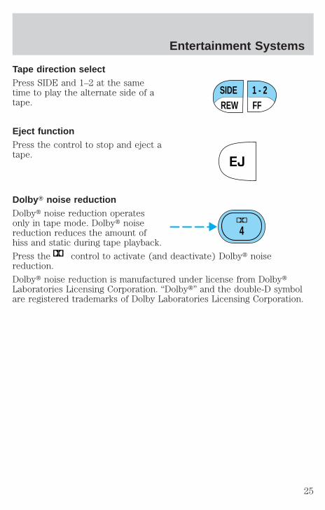
Tape direction selectPress SIDE and 1–2 at the sametime to play the alternate side of atape.
Eject functionPress the control to stop and eject atape.
Dolby T noise reductionDolbyt noise reduction operatesonly in tape mode. Dolbyt noisereduction reduces the amount ofhiss and static during tape playback.
Press the control to activate (and deactivate) Dolbyt noisereduction.
Dolbyt noise reduction is manufactured under license from DolbytLaboratories Licensing Corporation. “Dolbyt” and the double-D symbolare registered trademarks of Dolby Laboratories Licensing Corporation.
SIDEREW FF
1 - 2
EJ
4
Entertainment Systems
25
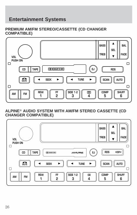
PREMIUM AM/FM STEREO/CASSETTE (CD CHANGERCOMPATIBLE)
ALPINET AUDIO SYSTEM WITH AM/FM STEREO CASSETTE (CDCHANGER COMPATIBLE)
SCAN
VOLPUSH ON
REW1
FF2
SIDE 1.23 4
COMP5
SHUFF6
AUTOTUNESEEK
SEL
BAL
FADE
MUTE
FMAM
EJ
BASS
TREB
CD TAPE RDS
SEEKMUTE TUNE SCAN AUTO
VOLPUSH ON
BASS
TREB
BAL
FADE
SEL
CD TAPE RDSEJ
AM FMREW1
FF2
SIDE 1-23 4
COMP5
SHUFF6
DSP
Entertainment Systems
26

Your audio system is equipped with selective lighting, a unique lightingstrategy. This lighting feature is operable when the headlamps areilluminated. During the operation of any selected mode, lighting for theindividual function controls will either illuminate or turn off. Thosecontrols which have a function for the specific mode of operationselected will be lit, while the controls which have no function for thatmode will be turned off.
Your vehicle is equipped with a delayed accessory feature. This featureenables the audio playing media to continue playing up to 10 minutesafter the ignition has been turned off, or until a door is opened.
Volume/power controlPress the control to turn the audiosystem on or off.
Turn the control to raise or lowervolume.
If the volume is set above a certain level and the ignition is turned off,the volume will come back on at a “nominal” listening level when theignition switch is turned back on.
Speed sensitive volume (if equipped)With this feature, radio volume automatically changes slightly withvehicle speed to compensate for road and wind noise.
The recommended level for speed sensitive volume is from level 1through level 3. Level 0 turns the speed sensitive volume off and level 7is the maximum setting.
VOLPUSH ON
VOLPUSH ON
Entertainment Systems
27

With the radio on, press and holdthe volume control for five seconds,until the display reads SPEED VOL,then press:
• to increase volumecompensation
• to decrease or shut off thevolume compensation
Bass adjustThe bass adjust control allows youto increase or decrease the audiosystem’s bass output.
Press the BASS control. Use theSEL control to increase or decreasethe amount of bass.
Treble adjustThe treble adjust control allows youto increase or decrease the audiosystem’s treble output.
Press the TREB control. Use theSEL control to increase or decreasethe amount of treble.
VOLPUSH ON
SEL
SEL
BASS
TREB
SEL
BASS
TREB
Entertainment Systems
28

Speaker balance adjustSpeaker sound distribution can beadjusted between the right and leftspeakers.
Press the BAL control. Use the SELcontrol to adjust the sound betweenthe speakers.
Speaker fade adjustSpeaker sound can be adjustedbetween the front and rearspeakers.
Press the FADE control. Use theSEL control to adjust the soundbetween the front and rearspeakers.
Seek functionThe seek function control works in radio, tape or CD mode (ifequipped).
Seek function in radio mode• Press to find the next
listenable station down thefrequency band.
• Press to find the next listenable station up the frequency band.
Seek function in tape mode• Press to listen to the previous
selection on the tape or return tothe beginning of the currentselection.
• Press to listen to the next selection on the tape.
SEL
BAL
FADE
SEL
BAL
FADE
SEEK
SEEK
Entertainment Systems
29
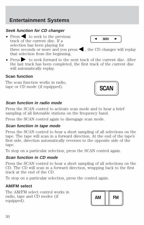
Seek function for CD changer• Press to seek to the previous
track of the current disc. If aselection has been playing forthree seconds or more and you press , the CD changer will replaythat selection from the beginning.
• Press to seek forward to the next track of the current disc. Afterthe last track has been completed, the first track of the current discwill automatically replay.
Scan functionThe scan function works in radio,tape or CD mode (if equipped).
Scan function in radio modePress the SCAN control to activate scan mode and to hear a briefsampling of all listenable stations on the frequency band.
Press the SCAN control again to disengage scan mode.
Scan function in tape modePress the SCAN control to hear a short sampling of all selections on thetape. The tape will scan in a forward direction. At the end of the tape’sfirst side, direction automatically reverses to the opposite side of thetape.
To stop on a particular selection, press the SCAN control again.
Scan function in CD modePress the SCAN control to hear a short sampling of all selections on theCD. The CD will scan in a forward direction, wrapping back to the firsttrack at the end of the CD.
To stop on a particular selection, press the control again.
AM/FM selectThe AM/FM select control works inradio, tape and CD modes (ifequipped).
SEEK
SCAN
FMAM
Entertainment Systems
30
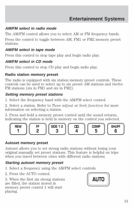
AM/FM select in radio modeThe AM/FM control allows you to select AM or FM frequency bands.
Press the control to toggle between AM, FM1 or FM2 memory presetstations.
AM/FM select in tape modePress this control to stop tape play and begin radio play.
AM/FM select in CD modePress this control to stop CD play and begin radio play.
Radio station memory presetThe radio is equipped with six station memory preset controls. Thesecontrols can be used to select up to six preset AM stations and twelveFM stations (six in FM1 and six in FM2).
Setting memory preset stations1. Select the frequency band with the AM/FM select control.
2. Select a station. Refer to Tune adjust or Seek function for moreinformation on selecting a station.
3. Press and hold a memory preset control until the sound returns,indicating the station is held in memory on the control you selected.
Autoset memory presetAutoset allows you to set strong radio stations without losing youroriginal manually set preset stations. This feature is helpful on tripswhen you travel between cities with different radio stations.
Starting autoset memory preset1. Select a frequency using the AM/FM select controls.
2. Press the AUTO control.
3. When the first six strong stationsare filled, the station stored inmemory preset control 1 will startplaying.
REW1
FF2
SIDE 1.23 4
COMP5
SHUFF6
AUTO
Entertainment Systems
31

If there are less than six strong stations available on the frequency band,the remaining memory preset controls will all store the last strongstation available.
To deactivate autoset and return to your audio system’s manually setmemory stations, press the control again.
Setting the clock with radio data system (RDS) feature(if equipped)This feature applies to vehicles not equipped with a separate, instrumentpanel mounted clock. If your vehicle has a separate clock, please refer toClock in this chapter.
Press the RDS control until SELECTHOUR or SELECT MINS isdisplayed.
Use the SEL control to manually setthe time.
• Press to increasehours/minutes.
• Press to decreasehours/minutes.
Tape/CD select• To begin tape play (with a tape
loaded into the audio system)while in the radio or CD mode,press the TAPE control. Press thebutton during rewind or fast forward to stop the rewind or fastforward function.
• To begin CD play (if equippedwith CD changer), ensure thatthe CDs are loaded. Press the CDcontrol. The first track of the discwill begin playing. After that, CD play will begin where it stopped last.
Do not insert any promotional (odd shaped or sized) discs, ordiscs with removable labels into the CD player as jamming mayoccur.
RDS
SEL
CD TAPE
CD TAPE
Entertainment Systems
32

RewindThe rewind control works in tapeand CD modes.
• In tape mode, radio play willcontinue until rewind is stopped(with the TAPE control) or thebeginning of the tape is reached.
• In CD mode, pressing the REW control for less than three secondsresults in slow rewind. Pressing the control for more than threeseconds results in fast rewind.
Fast forwardThe fast forward control works intape and CD modes (if equipped).
• In the tape mode, tape directionwill automatically reverse whenthe end of the tape is reached.
• In CD mode, pressing the control for less than three seconds results inslow forward action. Pressing the control for more than three secondsresults in fast forward action.
Tape direction selectPress SIDE 1–2 to play the alternateside of a tape.
Eject functionPress the control to stop and eject atape.
REW1
FF2
SIDE 1-23
EJ
Entertainment Systems
33

Dolby T noise reductionDolbyt noise reduction operatesonly in tape mode. Dolbyt noisereduction reduces the amount ofhiss and static during tape playback.
Press the control to activate(and deactivate) Dolbyt noise reduction.
The Dolbyt noise reduction system is manufactured under license fromDolby Laboratories Licensing Corporation. Dolbyt and the double-Dsymbol are registered trademarks of Dolbyt Labratories LicensingCorporation.
Compression featureCompression adjust brings soft andloud CD passages together for amore consistent listening level.
Press the COMP control to activateand deactivate compression adjust.
The effect of the feature varies with the music content.
Shuffle featureThe shuffle feature operates in CDmode and plays all tracks on thecurrent disc in random order. Ifequipped with the CD changer, theshuffle feature continues to the nextdisc after all tracks are played.
Press the SHUFFLE control to start this feature. Random order play willcontinue until the SHUFFLE control is pressed again.
Phone modeThis feature allows you to controlthe factory-installed cellular phone(if equipped) through the radiocontrols.
• Press the phone/mute control to enter phone mode. The playing mediawill mute.
4
COMP5
SHUFF6
MUTE
Entertainment Systems
34
• Use SEEK, TUNE or radio presets 1 through 6 to select a phonenumber previously programmed in the phone.
• Press the phone/mute control again to send and end calls.
This control will mute the playing media even if your vehicle is notequipped with a factory-installed cellular phone.
Press the control again to return to the playing media.
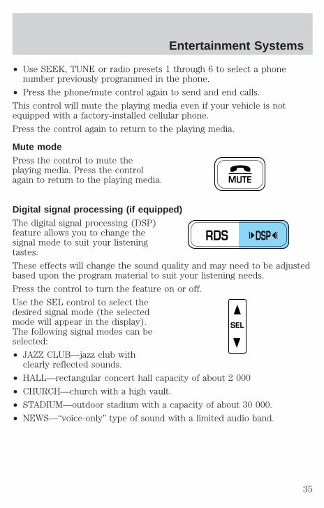
Mute modePress the control to mute theplaying media. Press the controlagain to return to the playing media.
Digital signal processing (if equipped)The digital signal processing (DSP)feature allows you to change thesignal mode to suit your listeningtastes.
These effects will change the sound quality and may need to be adjustedbased upon the program material to suit your listening needs.
Press the control to turn the feature on or off.
Use the SEL control to select thedesired signal mode (the selectedmode will appear in the display).The following signal modes can beselected:
• JAZZ CLUB—jazz club withclearly reflected sounds.
• HALL—rectangular concert hall capacity of about 2 000
• CHURCH—church with a high vault.
• STADIUM—outdoor stadium with a capacity of about 30 000.
• NEWS—“voice-only” type of sound with a limited audio band.
MUTE
RDS DSP
SEL
Entertainment Systems
35

Press the DSP control until one ofthe following appears:
• ALL SEATS
• DRIVER SEAT
• REAR SEATS
Use the SELECT control to changethe equalization to the desiredmode.
Radio data system (RDS) featureThis feature allows your audio system to receive station identification orprogram type from RDS-equipped FM radio stations.
The Federal Communications Commission (FCC) and the Canadian Radioand Telecommunications Commission (CRTC) recommend FM radiobroadcasters to use RDS technology to transmit information. FM radiostations are independently operated and individually elect to use RDStechnology to transmit station ID and program type as desired.
Press the RDS control until RDS ONor RDS OFF appears in the display.
Use the SEL control to enable (ON)or disable (OFF) the feature. Withthe RDS activated, press the SELcontrol to scroll through thefollowing selections:
Traffic• Press the RDS control until
TRAFFIC is displayed.
RDS DSP
SEL
RDS
SEL
RDS
Entertainment Systems
36

• Use the SEL control to select ONor OFF. With the feature on, usethe SEEK or SCAN control tofind a radio station broadcasting atraffic report (if it is broadcastingRDS data).
Traffic information is not available in most U.S. markets.
Program type• Press the RDS control until the
FIND program type is displayed.
• Use the SEL control to select theprogram type. With the featureon, use the SEEK or SCANcontrol to find the desiredprogram type from the followingselections:
• Classic
• Country
• Info
• Jazz
• Oldies
• R & B
• Religious
• Rock
• Soft
• Top 40
Show• With RDS activated, press the
RDS control until SHOW isdisplayed.
SEL
RDS
SEL
RDS
Entertainment Systems
37
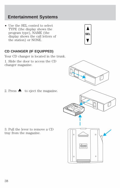
• Use the SEL control to selectTYPE (the display shows theprogram type), NAME (thedisplay shows the call letters ofthe station) or NONE.
CD CHANGER (IF EQUIPPED)Your CD changer is located in the trunk.
1. Slide the door to access the CDchanger magazine.
2. Press to eject the magazine.
3. Pull the lever to remove a CDtray from the magazine.
SEL
Entertainment Systems
38

4. Insert one disc into each CD trayof the magazine (up to 6 discs).Ensure that the label side is facingup.
If you pull too hard on the discholder, the disc holder may comecompletely out of the magazine. Ifthis happens, reinsert the discholder back into the magazine.
5. Insert each CD tray, with the discloaded, all the way into the CDmagazine.
6. Insert the CD magazine into thechanger.
7. Slide the door to the left to close.
Use only compact discs containingthis mark.
The magazine does not need to be full for the changer to operate.
Entertainment Systems
39
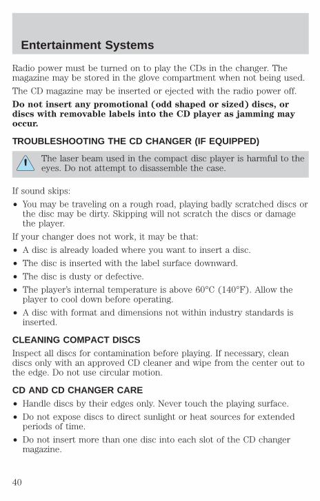
Radio power must be turned on to play the CDs in the changer. Themagazine may be stored in the glove compartment when not being used.
The CD magazine may be inserted or ejected with the radio power off.
Do not insert any promotional (odd shaped or sized) discs, ordiscs with removable labels into the CD player as jamming mayoccur.
TROUBLESHOOTING THE CD CHANGER (IF EQUIPPED)
The laser beam used in the compact disc player is harmful to theeyes. Do not attempt to disassemble the case.
If sound skips:
• You may be traveling on a rough road, playing badly scratched discs orthe disc may be dirty. Skipping will not scratch the discs or damagethe player.
If your changer does not work, it may be that:
• A disc is already loaded where you want to insert a disc.
• The disc is inserted with the label surface downward.
• The disc is dusty or defective.
• The player’s internal temperature is above 60°C (140°F). Allow theplayer to cool down before operating.
• A disc with format and dimensions not within industry standards isinserted.
CLEANING COMPACT DISCSInspect all discs for contamination before playing. If necessary, cleandiscs only with an approved CD cleaner and wipe from the center out tothe edge. Do not use circular motion.
CD AND CD CHANGER CARE• Handle discs by their edges only. Never touch the playing surface.
• Do not expose discs to direct sunlight or heat sources for extendedperiods of time.
• Do not insert more than one disc into each slot of the CD changermagazine.
Entertainment Systems
40

Do not insert any promotional (odd shaped or sized) discs, ordiscs with removable labels into the CD player as jamming mayoccur.
CLEANING CASSETTE PLAYER (IF EQUIPPED)Clean the tape player head with a cassette cleaning cartridge after 10 to12 hours of play in order to maintain the best sound and operation.
CASSETTE AND CASSETTE PLAYER CARE• Use only cassettes that are 90 minutes long or less.
• Do not expose tapes to direct sunlight, high humidity, extreme heat orextreme cold. Allow tapes that may have been exposed to extremetemperatures to reach a moderate temperature before playing.
• Tighten very loose tapes by inserting a finger or pencil into the holeand turning the hub.
• Remove loose labels before inserting tapes.
• Do not leave tapes in the cassette player for a long time when notbeing played.
RADIO FREQUENCY INFORMATIONThe Federal Communications Commission (FCC) and the Canadian Radioand Telecommunications Commission(CRTC) establish the frequenciesAM and FM stations may use for their broadcasts. Allowable frequenciesare:
AM 530, 540–1600, 1610 kHz
FM 87.7, 87.9–107.7, 107.9 MHz
Not all frequencies are used in a given area.
Entertainment Systems
41

RADIO RECEPTION FACTORSThree factors can affect radio reception:
• Distance/strength. The further an FM signal travels, the weaker it is.The listenable range of the average FM station is approximately 40 km(24 miles). This range can be affected by “signal modulation.” Signalmodulation is a process radio stations use to increase theirstrength/volume relative to other stations.
• Terrain. Hills, mountains and tall buildings between your vehicle’santenna and the radio station signal can cause FM reception problems.Static can be caused on AM stations by power lines, electric fences,traffic lights and thunderstorms. Moving away from an interferingstructure (out of its “shadow”) returns your reception to normal.
• Station overload. Weak signals are sometimes captured by strongersignals when you pass a broadcast tower. A stronger signal maytemporarily overtake a weaker signal and play while the weak stationfrequency is displayed.
The audio system automatically switches to single channel reception if itwill improve the reception of a station normally received in stereo.
AUDIO SYSTEM WARRANTIES AND SERVICERefer to the Warranty Guide for audio system warranty information.
If service is necessary, see your dealer or a qualified technician.
Entertainment Systems
42

ELECTRONIC AUTOMATIC TEMPERATURE CONTROL (EATC)SYSTEMThe EATC system will maintain aselected temperature andautomatically control airflow. Youcan override automatic operationwith any of the override controls,the fan speed control or the steeringwheel controls (if equipped).
Turning the EATC onPress AUTO, any of the overridecontrols or the fan speed control.The EATC will only operate whenthe vehicle is running.
Turning the EATC system offPress OFF. The outside temperaturefunction will continue to operateuntil the ignition is turned off.
Automatic operationPress AUTO and select the desired temperature. The selectedtemperature and the word AUTO will appear in the display window. TheEATC system will either heat or cool to achieve the selectedtemperature. The system will automatically determine fan speed, airflowlocation and if outside air or recirculated air is required. Fan speedremains automatic unless the fan speed control is pressed or the steeringwheel fan speed control (if equipped) is pressed.
When in AUTO and weather conditions require heat, air will be sent tothe floor. However, if the engine is not warm enough to provide heat, thefan will be at a low speed and the air will be directed to the windshield.In approximately 31⁄2 minutes or less, the fan speed will start to increaseand the airflow location will change to the floor area.
˚F
AUTO
EXT OFF AUTO MAXA/C
FRONT
REAR
˚F
AUTO
EXT OFF AUTO MAXA/C
FRONT
REAR
EXT OFF AUTO MAXA/C
Climate Controls
43

If unusual conditions exist (i.e.-window fogging, etc.), the manualoverride controls allow you to select airflow locations and the fan controlallows you to adjust fan speed as necessary.
Temperature selectionThe display window indicates theselected temperature, function(AUTO or one of the overridecontrols) and manual control of fanspeed ( ) if automatic fan speedis not desired.
To control the temperature, selectany temperature between 18°C(65°F) and 29°C (85°F) by pressingthe temperature control.
For continuous maximum cooling, push the temperature control until16°C (60°F) is shown in the display window. The EATC will continuemaximum cooling (disregarding the displayed temperature) until awarmer temperature is selected by pressing the temperature control.
For continuous maximum heating, push the temperature control until32°C (90°F) is shown in the display window. The EATC will continuemaximum heating (disregarding the displayed temperature) until acooler temperature is selected by pressing the temperature control.
Temperature conversionPress MAX A/C and FRONT atthe same time (for one second) toswitch between Fahrenheit andCelsius.
If your vehicle has an English/Metric (E/M) control to change yourelectronic instrument cluster (if equipped) and the message center (ifequipped) from English to Metric, this control will also change thetemperature display. Refer to Electronic Message Center in the Drivercontrols chapter.
˚F
AUTO
FRONT
REAR
˚C
EXT
EXT OFF AUTO MAXA/C
FRONT
REAR
Climate Controls
44

Fan speed ( )When AUTO is pressed, fan speed isadjusted automatically for existingconditions. You can override fanspeed at any time. To control fanspeed manually, press the fancontrol or the steering wheel fanspeed control (if equipped) tocancel automatic fan speedoperation. Press the control up forhigher fan speed or down for lowerfan speed. Press the steering wheel control (if equipped) up for higherfan speed or down for lower fan speed.
The display will show and a bargraph to indicate manual fanoperation and relative speed.
To return to automatic fan operation, press AUTO.Manual override controlsThe override controls allow you todetermine where airflow is directed.To return to full automatic control,press AUTO.
The air conditioning compressor canoperate in all modes except . It will also operate only when requiredwhen AUTO has been selected. However, the air conditioning will onlyfunction if the outside temperature is about 6°C (43°F) or higher.
Since the air conditioner removes considerable moisture from the airduring operation, it is normal if clear water drips on the ground underthe air conditioner drain while the system is working and even after youhave stopped the vehicle.
• MAX A/C-Uses recirculated air to cool the vehicle. The temperaturedisplay will remain unchanged and air will be cooled based on theselected temperature. To exit, press AUTO or any other overridecontrols. MAX A/C is noisier than normal A/C but more economicaland will cool the inside of the vehicle faster. Airflow is from theinstrument panel registers. This mode can also be used to preventundesirable odors from entering the vehicle.
EXT OFF AUTO MAXA/C
˚F
AUTO
˚F
AUTO
EXT OFF AUTO MAXA/C
FRONT
REAR
Climate Controls
45
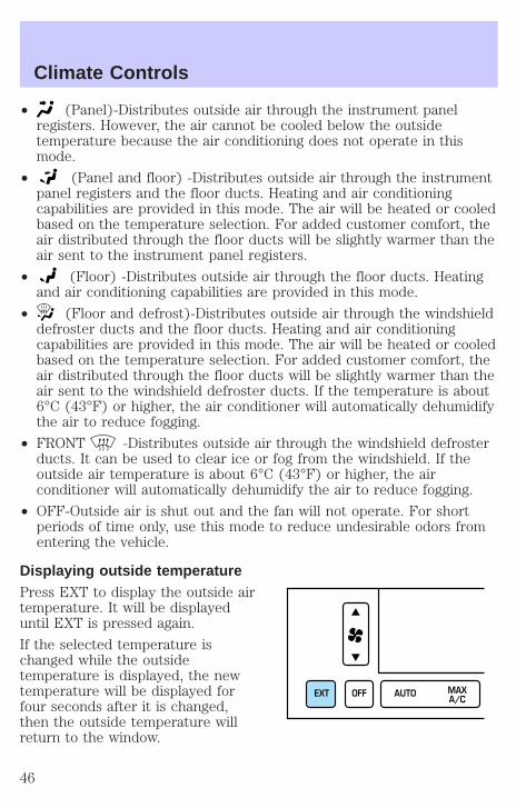
• (Panel)-Distributes outside air through the instrument panelregisters. However, the air cannot be cooled below the outsidetemperature because the air conditioning does not operate in thismode.
• (Panel and floor) -Distributes outside air through the instrumentpanel registers and the floor ducts. Heating and air conditioningcapabilities are provided in this mode. The air will be heated or cooledbased on the temperature selection. For added customer comfort, theair distributed through the floor ducts will be slightly warmer than theair sent to the instrument panel registers.
• (Floor) -Distributes outside air through the floor ducts. Heatingand air conditioning capabilities are provided in this mode.
• (Floor and defrost)-Distributes outside air through the windshielddefroster ducts and the floor ducts. Heating and air conditioningcapabilities are provided in this mode. The air will be heated or cooledbased on the temperature selection. For added customer comfort, theair distributed through the floor ducts will be slightly warmer than theair sent to the windshield defroster ducts. If the temperature is about6°C (43°F) or higher, the air conditioner will automatically dehumidifythe air to reduce fogging.
• FRONT -Distributes outside air through the windshield defrosterducts. It can be used to clear ice or fog from the windshield. If theoutside air temperature is about 6°C (43°F) or higher, the airconditioner will automatically dehumidify the air to reduce fogging.
• OFF-Outside air is shut out and the fan will not operate. For shortperiods of time only, use this mode to reduce undesirable odors fromentering the vehicle.
Displaying outside temperaturePress EXT to display the outside airtemperature. It will be displayeduntil EXT is pressed again.
If the selected temperature ischanged while the outsidetemperature is displayed, the newtemperature will be displayed forfour seconds after it is changed,then the outside temperature willreturn to the window.
EXT OFF AUTO MAXA/C
Climate Controls
46
If a manual override function is selected while the outside temperature isdisplayed, the new function will be displayed for four seconds after it ischanged, then the outside temperature will return to the window alongwith the override selection.
The outside temperature reading is most accurate when the vehicle ismoving. Higher readings may be obtained when the vehicle is notmoving. The readings that you get may not agree with temperaturesgiven on the radio due to differences in vehicle and station locations.
Operating tips• In humid weather, select (Defrost) before driving. This will
reduce fogging on your windshield. Once the windshield has beencleared, operate the climate control system as desired.
• To reduce humidity buildup inside the vehicle in cold weatherconditions, do not drive with the climate control system in the OFF orMAX A/C position.
• To reduce humidity buildup inside the vehicle in warm weatherconditions, do not drive with the climate control system in the OFFposition.
• Under normal weather conditions, your vehicle’s climate controlsystem should be left in any position other than MAX A/C or OFFwhen the vehicle is parked. This allows the vehicle to “breathe”through the outside air inlet duct.
• Under snowy or dirty weather conditions, your vehicle’s climatecontrol system should be left in the OFF position when the vehicle isparked. This allows the climate control system to be free fromcontamination of outside pollutants.
• If your vehicle has been parked with the windows closed during warmweather conditions, the air conditioner will perform more efficiently incooling the vehicle if driven for two or three minutes with thewindows open. This will force most of the hot, stale air out of thevehicle. Once the vehicle has been “aired out”, operate the climatecontrol system as desired.
• Do not place objects under the front seat that will interfere with theairflow to the rear seats.
• Remove any snow, ice or leaves from the air intake area at the base ofthe windshield.
Climate Controls
47

• If your vehicle has been parked with the windows closed during hotweather, the air conditioner will do a much faster job of cooling if youdrive for two or three minutes with the windows open. This will forcemost of the hot, stale air out of the vehicle. Then operate the airconditioner as you would normally.
• Do not place objects over the defroster outlets. These objects mayblock airflow and reduce visibility through your windshield. Avoidplacing small objects on top of your instrument panel. These objectscan fall down into the defroster outlets and block airflow, in additionto, damaging the climate control system.
To aid in defogging/demisting in cold weather conditions:
1. Select .
2. Set the temperature control to full heat
3. Set the fan speed to HI
4. Direct the outer panel vents towards the side windows
To increase airflow to the outer panel vents, close the central panelvents.
Do not place objects on top of the instrument panel, as theseobjects may become projectiles in a collision or sudden stop.
REAR WINDOW DEFROSTERThe rear defroster control is locatedon the instrument panel.
Press the rear defroster control toclear the rear window of thin iceand fog.
• A small LED will illuminate whenthe rear defroster is activated.
The ignition must be in the ON position to operate the rear windowdefroster.
The defroster turns off automatically after 10 minutes or when theignition is turned to the OFF position. To manually turn off the defrosterbefore 10 minutes have passed, push the control again.
FRONT
REAR
Climate Controls
48
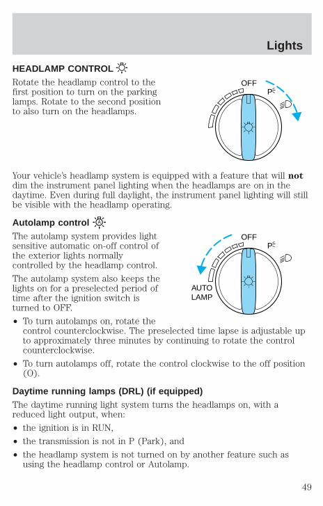
HEADLAMP CONTROLRotate the headlamp control to thefirst position to turn on the parkinglamps. Rotate to the second positionto also turn on the headlamps.
Your vehicle’s headlamp system is equipped with a feature that will notdim the instrument panel lighting when the headlamps are on in thedaytime. Even during full daylight, the instrument panel lighting will stillbe visible with the headlamp operating.
Autolamp controlThe autolamp system provides lightsensitive automatic on-off control ofthe exterior lights normallycontrolled by the headlamp control.
The autolamp system also keeps thelights on for a preselected period oftime after the ignition switch isturned to OFF.
• To turn autolamps on, rotate thecontrol counterclockwise. The preselected time lapse is adjustable upto approximately three minutes by continuing to rotate the controlcounterclockwise.
• To turn autolamps off, rotate the control clockwise to the off position(O).
Daytime running lamps (DRL) (if equipped)The daytime running light system turns the headlamps on, with areduced light output, when:
• the ignition is in RUN,
• the transmission is not in P (Park), and
• the headlamp system is not turned on by another feature such asusing the headlamp control or Autolamp.
OFFP
OFF
AUTOLAMP
P
Lights
49
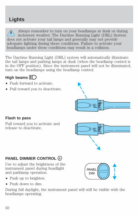
Always remember to turn on your headlamps at dusk or duringinclement weather. The Daytime Running Light (DRL) System
does not activate your tail lamps and generally may not provideadequate lighting during these conditions. Failure to activate yourheadlamps under these conditions may result in a collision.
The Daytime Running Light (DRL) system will automatically illuminatethe tail lamps and parking lamps at dusk (when the headlamp control isin the OFF position). Since the instrument panel will not be illuminated,turn on the headlamps using the headlamp control.
High beams• Push forward to activate.
• Pull toward you to deactivate.
Flash to passPull toward you to activate andrelease to deactivate.
PANEL DIMMER CONTROLUse to adjust the brightness of theinstrument panel during headlightand parklamp operation.
• Push up to brighten.
• Push down to dim.
During full daylight, the instrument panel will still be visible with theheadlamps operating.
HILO
F
SOFF
HILO
F
SOFF
PANELDIM
Lights
50
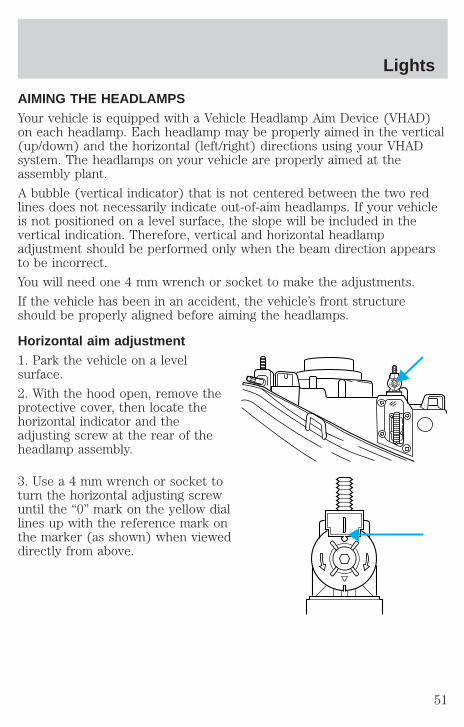
AIMING THE HEADLAMPSYour vehicle is equipped with a Vehicle Headlamp Aim Device (VHAD)on each headlamp. Each headlamp may be properly aimed in the vertical(up/down) and the horizontal (left/right) directions using your VHADsystem. The headlamps on your vehicle are properly aimed at theassembly plant.
A bubble (vertical indicator) that is not centered between the two redlines does not necessarily indicate out-of-aim headlamps. If your vehicleis not positioned on a level surface, the slope will be included in thevertical indication. Therefore, vertical and horizontal headlampadjustment should be performed only when the beam direction appearsto be incorrect.
You will need one 4 mm wrench or socket to make the adjustments.
If the vehicle has been in an accident, the vehicle’s front structureshould be properly aligned before aiming the headlamps.
Horizontal aim adjustment1. Park the vehicle on a levelsurface.
2. With the hood open, remove theprotective cover, then locate thehorizontal indicator and theadjusting screw at the rear of theheadlamp assembly.
3. Use a 4 mm wrench or socket toturn the horizontal adjusting screwuntil the “0” mark on the yellow diallines up with the reference mark onthe marker (as shown) when vieweddirectly from above.
Lights
51

Turning the horizontal adjustingscrew in the direction of the arrowchanges the horizontal aim asshown.
Vertical aim adjustment1. Park the vehicle on a levelsurface.
2. With the hood open, removeprotective cover, then locate thebubble level and the verticaladjustment screw. The adjustmentscrew is located on the outboardside of the headlamp.
3. The “U” and “D” on the bubbleindicate the directional change (upor down) of the vertical aim.
4. Use a 4 mm wrench or socket toturn the vertical adjusting screwuntil the bubble is centered betweenthe two red lines which representsthe “0” mark position.
5. Install protective cover.
When the horizontal and vertical indicators are set to the “0” mark, theheadlamp has been properly aimed.
D
U
Lights
52

TURN SIGNAL CONTROL• Push down to activate the left
turn signal.
• Push up to activate the right turnsignal.
INTERIOR LAMPS
Rear courtesy/reading lampsThe courtesy lamp lights when:
• any door is opened.
• any of the remote entry controlsare pressed and the ignition isOFF.
With the ignition key in the ACC orON position, the reading lamp canbe turned on by pressing the rockercontrol.
BULBS
Replacing exterior bulbsCheck the operation of the following lamps frequently:
• Headlamps
• Tail lamps
• Brakelamps
• High-mount brakelamp
• Turn signals
• Backup lamps
• License plate lamp
HILO
F
SOFF
Lights
53
Do not remove lamp bulbs unless they will be replaced immediately. If abulb is removed for an extended period of time, contaminants may enterthe lamp housings and affect performance.
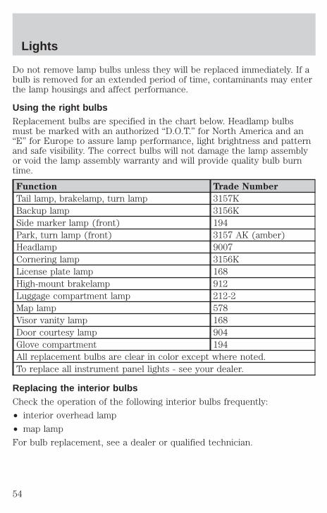
Using the right bulbsReplacement bulbs are specified in the chart below. Headlamp bulbsmust be marked with an authorized “D.O.T.” for North America and an“E” for Europe to assure lamp performance, light brightness and patternand safe visibility. The correct bulbs will not damage the lamp assemblyor void the lamp assembly warranty and will provide quality bulb burntime.
Function Trade Number
Tail lamp, brakelamp, turn lamp 3157KBackup lamp 3156KSide marker lamp (front) 194Park, turn lamp (front) 3157 AK (amber)Headlamp 9007Cornering lamp 3156KLicense plate lamp 168High-mount brakelamp 912Luggage compartment lamp 212-2Map lamp 578Visor vanity lamp 168Door courtesy lamp 904Glove compartment 194All replacement bulbs are clear in color except where noted.To replace all instrument panel lights - see your dealer.
Replacing the interior bulbsCheck the operation of the following interior bulbs frequently:
• interior overhead lamp
• map lamp
For bulb replacement, see a dealer or qualified technician.
Lights
54

Replacing headlamp bulbsTo remove the headlamp bulb:
1. Make sure headlamp switch is in OFF position.
2. Open the hood.
3. Twist the plastic knobs and remove the protective cover from the backof the headlamps. Lift the cover and pull towards the windshield.
4. Remove headlamp by taking theretainer pins out. Pull headlampforward to access bulb connector.
5. Disconnect the electricalconnector from the bulb by pullingrearward.
Lights
55

6. Remove the bulb retaining ring byrotating it counterclockwise (whenviewed from the rear) to free itfrom the bulb socket, and slide thering off the plastic base. Keep thering to retain the new bulb.
7. Without turning, remove the oldbulb from the lamp assembly bygently pulling it straight back out ofthe lamp assembly.
To install the new bulb:
Handle a halogen headlamp bulb carefully and keep out ofchildren’s reach. Grasp the bulb only by its plastic base and do
not touch the glass. The oil from your hand could cause the bulb tobreak the next time the headlamps are operated.
1. Insert the glass end of the new bulb into the lamp assembly. Turn thebulb left or right to align the grooves in the plastic base with the tabs inthe lamp assembly. When the grooves are aligned, push the bulb into thelamp assembly until the plastic base contacts the rear of the lampassembly.
2. Install the bulb retaining ring over the plastic base until it contacts therear of the socket by rotating it clockwise until you feel a “stop.”
3. Connect the electrical connector into the rear of the plastic base untilit snaps, locking it into position.
4. Turn the headlamps on and make sure they work properly. If theheadlamp was correctly aligned before you changed the bulb, you shouldnot need to align it again.
5. Carefully insert the headlamp assembly into the vehicle making surethe retainer pins are inserted into the proper holes and into the guides.
6. Install protective cover on vehicle locking it in place with knobs.
Lights
56
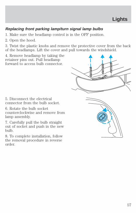
Replacing front parking lamp/turn signal lamp bulbs1. Make sure the headlamp control is in the OFF position.
2. Open the hood.
3. Twist the plastic knobs and remove the protective cover from the backof the headlamps. Lift the cover and pull towards the windshield.
4. Remove headlamp by taking theretainer pins out. Pull headlampforward to access bulb connector.
5. Disconnect the electricalconnector from the bulb socket.
6. Rotate the bulb socketcounterclockwise and remove fromlamp assembly.
7. Carefully pull the bulb straightout of socket and push in the newbulb.
8. To complete installation, followthe removal procedure in reverseorder.
Lights
57

Replacing high-mount brakelamp bulbs1. Remove the lamp cover by pryingup.
2. Rotate the bulb socketcounterclockwise and remove fromlamp assembly.
3. Carefully pull the bulb straightout of socket and push in the newbulb.
4. To complete installation, followthe removal procedure in reverseorder.
Replacing license plate lamp bulbs1. Remove two screws, grommetsand the license plate lamp assemblyfrom the trunk lid.
2. Carefully pull the bulb from thesocket and push in the new bulb.
3. Install the lamp assembly ontrunk lid with two grommets,ensuring the grommets are pushedall the way in to the trunk lid andsecure with two screws.
Replacing tail lamp/backup bulbsFor bulb replacement, see a dealer or qualified technician.
Lights
58
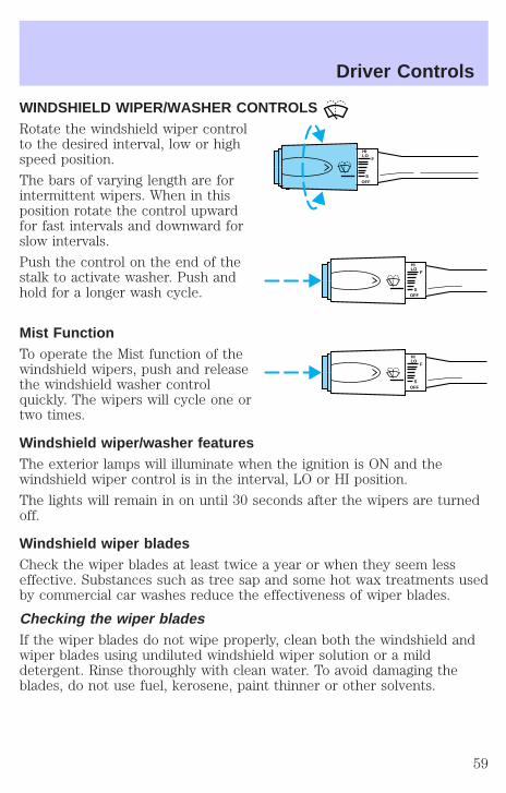
WINDSHIELD WIPER/WASHER CONTROLSRotate the windshield wiper controlto the desired interval, low or highspeed position.
The bars of varying length are forintermittent wipers. When in thisposition rotate the control upwardfor fast intervals and downward forslow intervals.
Push the control on the end of thestalk to activate washer. Push andhold for a longer wash cycle.
Mist FunctionTo operate the Mist function of thewindshield wipers, push and releasethe windshield washer controlquickly. The wipers will cycle one ortwo times.
Windshield wiper/washer featuresThe exterior lamps will illuminate when the ignition is ON and thewindshield wiper control is in the interval, LO or HI position.
The lights will remain in on until 30 seconds after the wipers are turnedoff.
Windshield wiper bladesCheck the wiper blades at least twice a year or when they seem lesseffective. Substances such as tree sap and some hot wax treatments usedby commercial car washes reduce the effectiveness of wiper blades.
Checking the wiper bladesIf the wiper blades do not wipe properly, clean both the windshield andwiper blades using undiluted windshield wiper solution or a milddetergent. Rinse thoroughly with clean water. To avoid damaging theblades, do not use fuel, kerosene, paint thinner or other solvents.
HILO
F
SOFF
HILO
F
SOFF
HILO
F
SOFF
Driver Controls
59
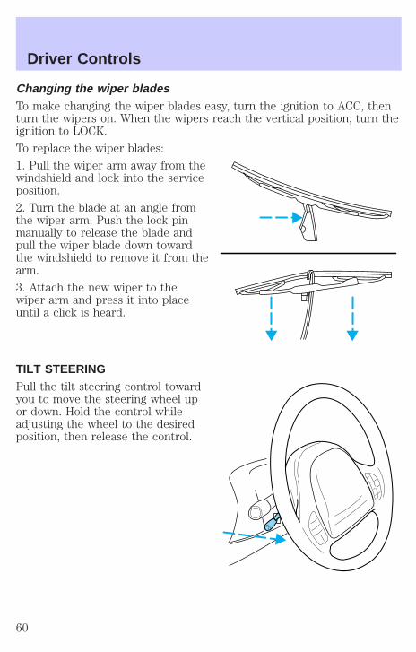
Changing the wiper bladesTo make changing the wiper blades easy, turn the ignition to ACC, thenturn the wipers on. When the wipers reach the vertical position, turn theignition to LOCK.
To replace the wiper blades:
1. Pull the wiper arm away from thewindshield and lock into the serviceposition.
2. Turn the blade at an angle fromthe wiper arm. Push the lock pinmanually to release the blade andpull the wiper blade down towardthe windshield to remove it from thearm.
3. Attach the new wiper to thewiper arm and press it into placeuntil a click is heard.
TILT STEERINGPull the tilt steering control towardyou to move the steering wheel upor down. Hold the control whileadjusting the wheel to the desiredposition, then release the control.
Driver Controls
60

Never adjust the steering wheel when the vehicle is moving.
ILLUMINATED VISOR MIRROR (IF EQUIPPED)To turn on the visor mirror lamps,lift the mirror cover.
CLOCK (IF EQUIPPED)If your vehicle is not equipped with an instrument panel mounted clock,refer to Setting the Clock section in the Entertainment chapter.
Press the right control to increasethe time displayed.
Press the left control to decreasethe time displayed.
Driver Controls
61
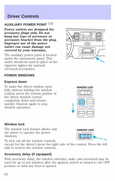
AUXILIARY POWER POINTPower outlets are designed foraccessory plugs only. Do nothang any type of accessory oraccessory bracket from the plug.Improper use of the poweroutlet can cause damage notcovered by your warranty.
The auxiliary power point is locatedunder the instrument panel. Thisoutlet should be used in place of thecigarette lighter for optionalelectrical accessories.
POWER WINDOWS
Express downTo make the driver window openfully without holding the windowcontrol, press the bottom portion ofthe driver window controlcompletely down and releasequickly. Depress again to stopwindow operation.
Window lockThe window lock feature allows onlythe driver to operate the powerwindows.
To lock out all the window controlsexcept for the driver’s press the right side of the control. Press the leftside to restore the window controls.
Accessory delay (if equipped)With accessory delay, the window switches, radio, and moonroof may beused for up to ten minutes after the ignition switch is turned to the OFFposition or until any door is opened.
VOLPUSH ON
TAPE
MUTE SEEK TUNE
AM FMREW FF SIDE 1 2 COMP SHUFF
CD EJ RDS
SCAN AUTO
1 2 3 4 5 6
BASS
TREB
SEL
BAL
FADE
EXT OFF MAXA/C
AUTO
FRONT
REAR
SELECT RESET
WINDOW LOCK
WINDOW LOCK
Driver Controls
62

MIRRORS
Automatic dimming inside rear view mirror (if equipped)Your vehicle is equipped with an inside rear view mirror which has anauto-dimming function (available as an option on the outside driver’s sidemirror). The electronic day/night mirror will change from the normalstate to the non-glare state when bright lights (glare) reach the mirror.When the mirror detects bright light from front or behind, it willautomatically adjust (darken) to minimize glare.
Do not block the sensor on thebackside of the mirror since thismay impair proper mirrorperformance.
Ensure the mirror is pulled downlow enough to prevent visibilityinterference with the moon roofcontrols. The mirror support armhas two pivot points which lets youadjust the mirror UP or DOWN and from SIDE to SIDE.
Press the control to turn the mirror on or off.
The mirror will automatically return to the normal state whenever thevehicle is placed in R (Reverse)(when the mirror is on) to ensure abright clear view when backing up.
Power side view mirrorsThe ignition must be in ACC or ON position to adjust the power sideview mirrors.
To adjust your mirrors:
1. Select L to adjust the left mirroror R to adjust the right mirror.
COMP MIRROR
L R
Driver Controls
63
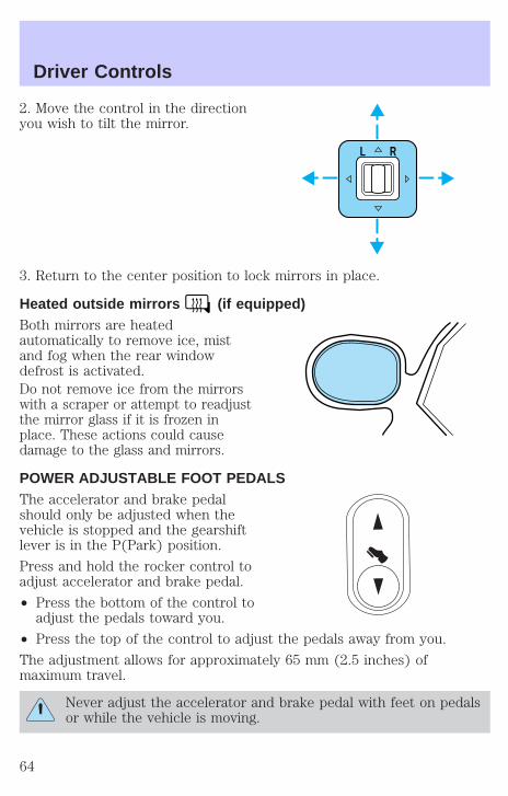
2. Move the control in the directionyou wish to tilt the mirror.
3. Return to the center position to lock mirrors in place.
Heated outside mirrors (if equipped)Both mirrors are heatedautomatically to remove ice, mistand fog when the rear windowdefrost is activated.Do not remove ice from the mirrorswith a scraper or attempt to readjustthe mirror glass if it is frozen inplace. These actions could causedamage to the glass and mirrors.
POWER ADJUSTABLE FOOT PEDALSThe accelerator and brake pedalshould only be adjusted when thevehicle is stopped and the gearshiftlever is in the P(Park) position.
Press and hold the rocker control toadjust accelerator and brake pedal.
• Press the bottom of the control toadjust the pedals toward you.
• Press the top of the control to adjust the pedals away from you.
The adjustment allows for approximately 65 mm (2.5 inches) ofmaximum travel.
Never adjust the accelerator and brake pedal with feet on pedalsor while the vehicle is moving.
L R
Driver Controls
64
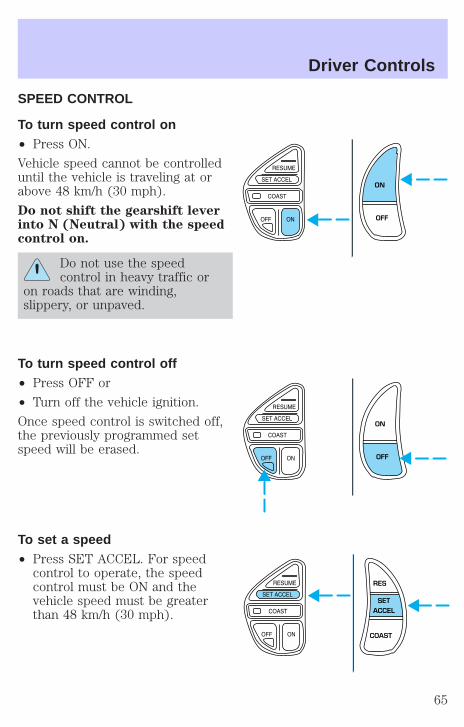
SPEED CONTROL
To turn speed control on• Press ON.
Vehicle speed cannot be controlleduntil the vehicle is traveling at orabove 48 km/h (30 mph).
Do not shift the gearshift leverinto N (Neutral) with the speedcontrol on.
Do not use the speedcontrol in heavy traffic or
on roads that are winding,slippery, or unpaved.
To turn speed control off• Press OFF or
• Turn off the vehicle ignition.
Once speed control is switched off,the previously programmed setspeed will be erased.
To set a speed• Press SET ACCEL. For speed
control to operate, the speedcontrol must be ON and thevehicle speed must be greaterthan 48 km/h (30 mph).
ON
OFF
ON
OFF
RES
SETACCEL
COAST
Driver Controls
65
If you drive up or down a steep hill, your vehicle speed may varymomentarily slower or faster than the set speed. This is normal.
Speed control cannot reduce the vehicle speed if it increases above theset speed on a downhill. If your vehicle speed is faster than the setspeed while driving on a downhill, you may want to shift to the nextlower gear or apply the brakes to reduce your vehicle speed.
If your vehicle slows down more than 16 km/h (10 mph) below your setspeed on an uphill, your speed control will disengage. This is normal.Pressing RES/RESUME will re-engage it.
Do not use the speed control in heavy traffic or on roads thatare winding, slippery, or unpaved.
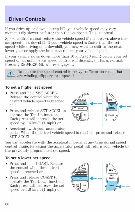
To set a higher set speed• Press and hold SET ACCEL.
Release the control when thedesired vehicle speed is reachedor
• Press and release SET ACCEL tooperate the Tap-Up function.Each press will increase the setspeed by 1.6 km/h (1 mph) or
• Accelerate with your acceleratorpedal. When the desired vehicle speed is reached, press and releaseSET ACCEL.
You can accelerate with the accelerator pedal at any time during speedcontrol usage. Releasing the accelerator pedal will return your vehicle tothe previously programmed set speed.
To set a lower set speed• Press and hold COAST. Release
the control when the desiredspeed is reached or
• Press and release COAST tooperate the Tap-Down function.Each press will decrease the setspeed by 1.6 km/h (1 mph) or
RES
SETACCEL
COAST
RES
SETACCEL
COAST
Driver Controls
66

• Depress the brake pedal. Whenthe desired vehicle speed isreached, press SET ACCEL.
To disengage speed control• Depress the brake pedal.
Disengaging the speed control willnot erase the previouslyprogrammed set speed.
Pressing OFF will erase thepreviously programmed set speed.
To return to a previously set speed• Press RES/RESUME. For
RES/RESUME to operate, thevehicle speed must be faster than48 km/h (30 mph).
RES
SETACCEL
COAST
ON
OFF
RES
SETACCEL
COAST
Driver Controls
67
Indicator light
Indicator messageThis message is displayed in theMessage Center when either theSET ACCEL or RES/RESUMEcontrols are pressed. It turns off when the speed control OFF is pressed,the brake is applied or the ignition is turned to the OFF position.
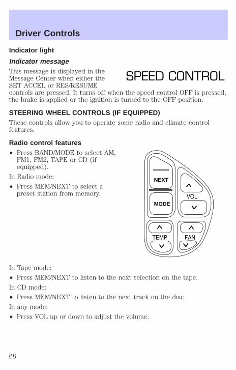
STEERING WHEEL CONTROLS (IF EQUIPPED)These controls allow you to operate some radio and climate controlfeatures.
Radio control features• Press BAND/MODE to select AM,
FM1, FM2, TAPE or CD (ifequipped).
In Radio mode:
• Press MEM/NEXT to select apreset station from memory.
In Tape mode:
• Press MEM/NEXT to listen to the next selection on the tape.
In CD mode:
• Press MEM/NEXT to listen to the next track on the disc.
In any mode:
• Press VOL up or down to adjust the volume.
SPEED CONTROL
NEXT
MODE
Driver Controls
68

Climate control features• Press TEMP up or down to adjust temperature.
• Press FAN up or down to adjust fan speed.
MOON ROOF (IF EQUIPPED)To open the moon roof:
• Press and release the control.
• For one-touch operation, pressand release the rear portion ofthe control; this will fully openthe moon roof.
• To stop one-touch operation atthe desired position, press andrelease the forward portion of thecontrol.
To close the moon roof:
• Press and hold the front portion of the control.
• To close from the vent position, press and hold the rear portion of thecontrol.
HOMELINKT UNIVERSAL TRANSCEIVER (IF EQUIPPED)The HomeLinkt Universal Transceiver, located on the driver’s visor,provides a convenient way to replace up to three hand-held transmitterswith a single built-in device. This feature will learn the radio frequencycodes of most current transmitters to operate garage doors, entry gates,security systems, entry door locks, and home or office lighting.
When programming your HomeLinkt Universal Transceiver, to agarage door or gate be sure that people and objects are out of
the way to prevent potential harm or damage.
Do not use the HomeLinkt Universal Transceiver with any garage dooropener that lacks safety stop and reverse features as required by U.S.federal safety standards (this includes any garage door opener modelmanufactured before April 1, 1982). A garage door which cannot detectan object, signaling the door to stop and reverse, does not meet currentU.S. federal safety standards. For more information on this matter, calltoll-free: 1–800–355–3515 or on the Internet at HomeLink.jci.com.
Driver Controls
69

ProgrammingDo not program the HomeLinkt Universal Transceiver with thevehicle parked in the garage.
1. Prepare for programming theHomeLinkt Universal Transceiver byerasing the three factory defaultcodes by holding down the twooutside buttons until the red lightbegins to flash after 20 seconds.Release both buttons.
2. Hold the end of your hand-heldtransmitter 5–14 cm (2–5 inches)away from the HomeLinkt UniversalTransceiver surface (located on your visor) while keeping the red light inview.
3. Using both hands simultaneouslypress and hold the hand-heldtransmitter button and the desiredHomeLinkt button. Do not releasethe buttons until step 4 has beencompleted.
Some entry gates and garage dooropeners may require you to replacestep 3 with the procedure in the “Canadian Programing” section.
4. The red light will flash slowly and then rapidly. Release both buttonswhen the red light flashes rapidly.
5. Follow steps 2 through 4 to program the remaining two buttons.
If you do not successfully program the HomeLinkt Universal Transceiverafter repeated attempts, refer to Rolling code programing whichfollows, or call toll-free customer assistance: 1–800–355–3515 or on theInternet at HomeLink.jci.com.
Driver Controls
70
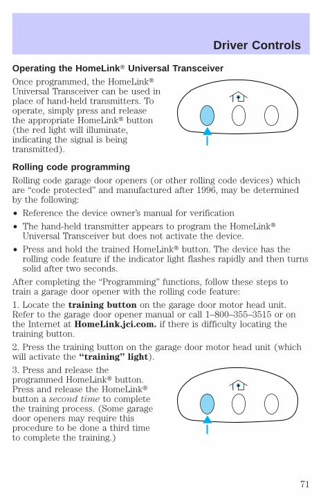
Operating the HomeLink T Universal TransceiverOnce programmed, the HomeLinktUniversal Transceiver can be used inplace of hand-held transmitters. Tooperate, simply press and releasethe appropriate HomeLinkt button(the red light will illuminate,indicating the signal is beingtransmitted).
Rolling code programmingRolling code garage door openers (or other rolling code devices) whichare “code protected” and manufactured after 1996, may be determinedby the following:
• Reference the device owner’s manual for verification
• The hand-held transmitter appears to program the HomeLinktUniversal Transceiver but does not activate the device.
• Press and hold the trained HomeLinkt button. The device has therolling code feature if the indicator light flashes rapidly and then turnssolid after two seconds.
After completing the “Programming” functions, follow these steps totrain a garage door opener with the rolling code feature:
1. Locate the training button on the garage door motor head unit.Refer to the garage door opener manual or call 1–800–355–3515 or onthe Internet at HomeLink.jci.com. if there is difficulty locating thetraining button.
2. Press the training button on the garage door motor head unit (whichwill activate the “training” light).
3. Press and release theprogrammed HomeLinkt button.Press and release the HomeLinktbutton a second time to completethe training process. (Some garagedoor openers may require thisprocedure to be done a third timeto complete the training.)
Driver Controls
71
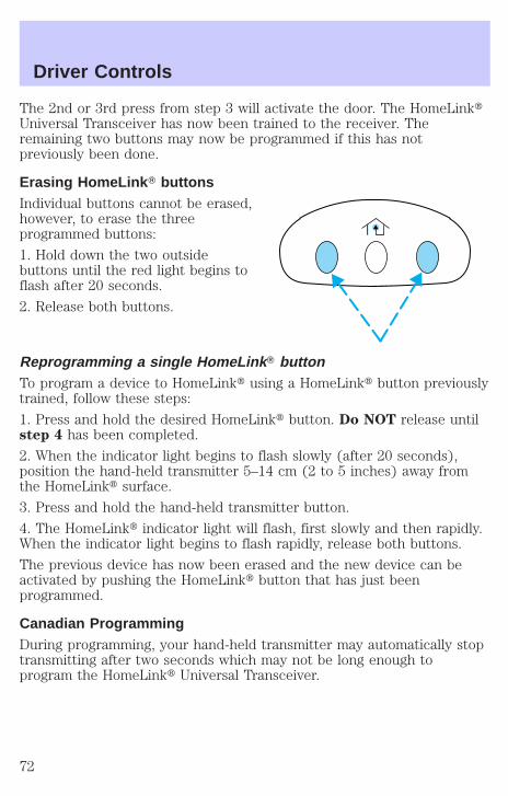
The 2nd or 3rd press from step 3 will activate the door. The HomeLinktUniversal Transceiver has now been trained to the receiver. Theremaining two buttons may now be programmed if this has notpreviously been done.
Erasing HomeLink T buttonsIndividual buttons cannot be erased,however, to erase the threeprogrammed buttons:
1. Hold down the two outsidebuttons until the red light begins toflash after 20 seconds.
2. Release both buttons.
Reprogramming a single HomeLink T buttonTo program a device to HomeLinkt using a HomeLinkt button previouslytrained, follow these steps:
1. Press and hold the desired HomeLinkt button. Do NOT release untilstep 4 has been completed.
2. When the indicator light begins to flash slowly (after 20 seconds),position the hand-held transmitter 5–14 cm (2 to 5 inches) away fromthe HomeLinkt surface.
3. Press and hold the hand-held transmitter button.
4. The HomeLinkt indicator light will flash, first slowly and then rapidly.When the indicator light begins to flash rapidly, release both buttons.
The previous device has now been erased and the new device can beactivated by pushing the HomeLinkt button that has just beenprogrammed.
Canadian ProgrammingDuring programming, your hand-held transmitter may automatically stoptransmitting after two seconds which may not be long enough toprogram the HomeLinkt Universal Transceiver.
Driver Controls
72
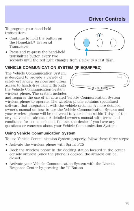
To program your hand-heldtransmitters:
• Continue to hold the button onthe HomeLinkt UniversalTransceiver.
• Press and re-press the hand-heldtransmitter button every twoseconds until the red light changes from a slow to a fast flash.
VEHICLE COMMUNICATION SYSTEM (IF EQUIPPED)The Vehicle Communication Systemis designed to provide a variety ofsafety enhancing services and offersaccess to hands-free calling throughthe Vehicle Communication Systemwireless phone. The system includesand requires the use of an activated Vehicle Communication Systemwireless phone to operate. The wireless phone contains specializedsoftware that integrates it with the vehicle systems. A more detailedowner’s manual on how to use the Vehicle Communication System andyour wireless phone will be delivered to your home within 7 days of theoriginal vehicle sale date. A detailed owner’s manual with terms andconditions for use is included. Contact the dealer if you have anyquestions or concerns about your Vehicle Communication System.
Using Vehicle Communication SystemTo use Vehicle Communication System properly, follow these three steps:
• Activate the wireless phone with Sprint PCS
• Dock the wireless phone in the docking station located in the centerconsole armrest (once the phone is docked, the armrest can beclosed)
• Activate your Vehicle Communication System with the LincolnResponse Center by pressing the “i” Button
S SINFO O. ..
Driver Controls
73

1. SOS BUTTON — In anemergency situation or for roadsideassistance, press this button tocontact the Lincoln ResponseCenter. A response centerrepresentative will locate yourvehicle and dispatch assistance if needed. Once a connection is made tothe Lincoln Response Center, only the response center representativewill be able to disconnect the call.
Vehicle Communication System will redial for roadside assistance 3 timesbefore showing on the audio display “CALL FAILED” because of networkcapacity or lack of analog coverage.
2. AUTOMATIC AIR BAG NOTIFICATION — If the air bag deploys, theVehicle Communication system automatically places a call to the LincolnResponse Center and a representative will dispatch help to your locationimmediately if requested. If the specialist is unable to reach you, theemergency service provider will be contacted and dispatched to yourlocation.
Vehicle Communication System will redial for automatic airbagnotification 5 times before showing on the audio display “CALL FAILED”because of network capacity or lack of analog coverage.
3. INFO BUTTON — Press thisbutton for route guidance andinformation regarding the points ofinterest such as ATM’s, restaurants,etc. The Lincoln Response Centerwill receive your request and helpyou find your way.
4. PHONE BUTTON — Place orreceive a call by pressing thisbutton. When making or receiving acall the audio system will muteautomatically. To make or receive a call, just press the phone button.Your Vehicle Communication System service includes the Sprint PCSVoice Command (SM) service. You can place voice-activated calls usingnames programmed in your web-address book or simply speak the phonenumber.
s s...o
INFO
MUTE
Driver Controls
74

Volume Control — Volume can becontrolled using the audio systemcontrols.
First Owner/First Time Activation• After receiving the wireless phone and welcome kit, please contact
Sprint PCS at 1–866–PCS-AUTO (1–866–727–2886) and select option“1” for activations. When calling Sprint PCS to activate your phone,please do not call from your new wireless phone.
Note: Following the three-month introductory period, you must continueto enroll in a Sprint PCS voice plan in order to enable any of the VehicleCommunication System features.
• Turn the ignition to “ACC”. Open the center console armrest and foldthe presenter arm out. Place the wireless phone in the dockingstation. If the phone is docked properly, the audio display should read“VCS ACTIVE”. The Vehicle Communication System will not functionif the phone is not properly docked.
• Press the “ i” Button and when voice communication is establishedwith the Lincoln Response Center, indicate that you are a newcustomer and the specialist will introduce you to the features. Thepurpose of this call is to verify that your Vehicle CommunicationSystem is active and functioning properly. In the event that theVehicle Communication System does not function properly, pleasecontact your Lincoln dealership for assistance.
Leased VehiclesIf the vehicle is leased, the wireless phone should be returned to thedealership at the end of the lease term. At the end of the lease term, youhave the option to purchase the wireless phone for the price of itsreplacement. Please be sure to contact Sprint PCS at 1–866–PCS-AUTO(1–866–727–2886) for wireless service options if you keep the phone orcall to deactivate your account prior to lease termination.
Second Owner/Re-LesseesThe Vehicle Communication System will not function without anactivated wireless phone with Sprint PCS. The wireless phone may bepurchased through Lincoln dealerships. Wireless service can be activatedwith Sprint PCS. Just following the steps in the “First Time Activation”section above.
VOLPUSH ON
Driver Controls
75

Vehicle Communication System Limitations• Vehicle Communication System services are available in the 48
contiguous states and Hawaii
• Vehicle Communication System services are not available in Alaska
• Only available within range of the cellular systems
• Connection limited by atmospheric and topographical conditions
• Connection limited by cellular network capabilities and infrastructure
• The wireless phone must have an active wireless service plan withSprint PCS and docked in the docking station located in the centerconsole for Vehicle Communication System to function properly
• The vehicle must be running or the ignition must be turned to either“ACC” or “RUN/ON” position
• May become inoperative if the vehicle is involved in an accident,damaging one or more components
• Sprint PCS Voice Command (SM) services are only available on theSprint PCS network
Global Positioning Satellites are used to deliver location information(only at the request of the vehicle occupants or in the event an airbagdeploys) and may not be available if signal is obstructed. (If a signal isunavailable, the last valid position obtained before the signal wasobstructed will be sent.)
Vehicle Communication System is powered by the vehicle’s battery andwill not operate if the battery is discharged or disconnected.
Vehicle Communication System specialist will make all reasonable effortsto contact the Public Safety service providers but cannot be heldresponsible for their response time or their activities.
Drivers have the responsibility to pay primary attention to the road anddrive safely. A driver may want to pull over to a safe parking spot beforeusing Vehicle Communication System services. Drivers who allowthemselves to become distracted may cause an accident. Please use thistechnology responsibly.
Due to the specialized Lincoln software contained within the phone, yourlocal Sprint PCS store is unable to provide service or replacement units.Issues or questions about equipment including the wireless phone shouldbe directed to your Lincoln dealer.
Driver Controls
76
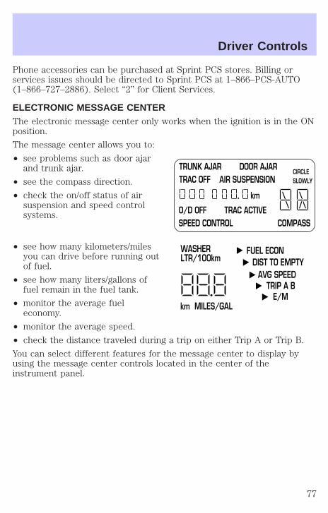
Phone accessories can be purchased at Sprint PCS stores. Billing orservices issues should be directed to Sprint PCS at 1–866–PCS-AUTO(1–866–727–2886). Select “2” for Client Services.
ELECTRONIC MESSAGE CENTERThe electronic message center only works when the ignition is in the ONposition.
The message center allows you to:
• see problems such as door ajarand trunk ajar.
• see the compass direction.
• check the on/off status of airsuspension and speed controlsystems.
• see how many kilometers/milesyou can drive before running outof fuel.
• see how many liters/gallons offuel remain in the fuel tank.
• monitor the average fueleconomy.
• monitor the average speed.
• check the distance traveled during a trip on either Trip A or Trip B.
You can select different features for the message center to display byusing the message center controls located in the center of theinstrument panel.
TRUNK AJAR DOOR AJARTRAC OFF AIR SUSPENSION
O/D OFF TRAC ACTIVESPEED CONTROL COMPASS
km
CIRCLE SLOWLY
FUEL ECON DIST TO EMPTY
AVG SPEEDTRIP A B
E/Mkm MILES/GAL
WASHER LTR/100km
Driver Controls
77
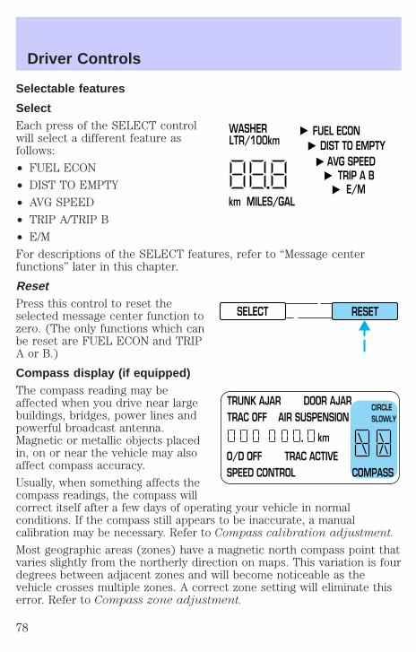
Selectable features
SelectEach press of the SELECT controlwill select a different feature asfollows:
• FUEL ECON
• DIST TO EMPTY
• AVG SPEED
• TRIP A/TRIP B
• E/M
For descriptions of the SELECT features, refer to “Message centerfunctions” later in this chapter.
ResetPress this control to reset theselected message center function tozero. (The only functions which canbe reset are FUEL ECON and TRIPA or B.)
Compass display (if equipped)The compass reading may beaffected when you drive near largebuildings, bridges, power lines andpowerful broadcast antenna.Magnetic or metallic objects placedin, on or near the vehicle may alsoaffect compass accuracy.
Usually, when something affects thecompass readings, the compass willcorrect itself after a few days of operating your vehicle in normalconditions. If the compass still appears to be inaccurate, a manualcalibration may be necessary. Refer to Compass calibration adjustment.
Most geographic areas (zones) have a magnetic north compass point thatvaries slightly from the northerly direction on maps. This variation is fourdegrees between adjacent zones and will become noticeable as thevehicle crosses multiple zones. A correct zone setting will eliminate thiserror. Refer to Compass zone adjustment.
FUEL ECON DIST TO EMPTY
AVG SPEEDTRIP A B
E/Mkm MILES/GAL
WASHER LTR/100km
SELECT RESET
TRUNK AJAR DOOR AJARTRAC OFF AIR SUSPENSION
O/D OFF TRAC ACTIVESPEED CONTROL COMPASS
km
CIRCLE SLOWLY
Driver Controls
78
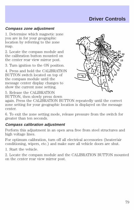
Compass zone adjustment1. Determine which magnetic zoneyou are in for your geographiclocation by referring to the zonemap.
2. Locate the compass module andthe calibration button mounted onthe center rear view mirror post.
3. Turn ignition to the ON position.
4. Press and hold the CALIBRATIONBUTTON switch located on top ofthe compass module until themessage center display changes toshow the current zone setting.
5. Release the CALIBRATIONBUTTON, then slowly press downagain. Press the CALIBRATION BUTTON repeatedly until the correctzone setting for your geographic location is displayed on the messagecenter.
6. To exit the zone setting mode, release pressure from the switch forgreater than ten seconds.
Compass calibration adjustmentPerform this adjustment in an open area free from steel structures andhigh voltage lines.
For optimum calibration, turn off all electrical accessories (heater/airconditioning, wipers, etc.) and make sure all vehicle doors are shut.
1. Start the vehicle.
2. Locate the compass module and the CALIBRATION BUTTON mountedon the center rear view mirror post.
1
2
3
4
56
7 8 9
10
11
12
13
1415
Driver Controls
79
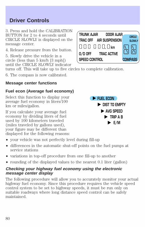
3. Press and hold the CALIBRATIONBUTTON for 2 to 4 seconds untilCIRCLE SLOWLY is displayed on themessage center.
4. Release pressure from the button.
5. Slowly drive the vehicle in acircle (less than 5 km/h [3 mph])until the CIRCLE SLOWLY indicatorturns off. This will take up to five circles to complete calibration.
6. The compass is now calibrated.
Message center functions
Fuel econ (Average fuel economy)Select this function to display youraverage fuel economy in liters/100km or miles/gallon.
If you calculate your average fueleconomy by dividing liters of fuelused by 100 kilometers traveled(miles traveled by gallons used),your figure may be different thandisplayed for the following reasons:
• your vehicle was not perfectly level during fill-up
• differences in the automatic shut-off points on the fuel pumps atservice stations
• variations in top-off procedure from one fill-up to another
• rounding of the displayed values to the nearest 0.1 liter (gallon)
Checking your highway fuel economy using the electronicmessage center displayThe following procedure will allow you to accurately monitor your actualhighway fuel economy. Since this procedure requires the vehicle speedcontrol system to be set to highway speeds, it must be run only onsuitable roadways where long distance speed control can be safelymaintained.
TRUNK AJAR DOOR AJARTRAC OFF AIR SUSPENSION
O/D OFF TRAC ACTIVESPEED CONTROL COMPASS
km
CIRCLE SLOWLY
FUEL ECON DIST TO EMPTY
AVG SPEEDTRIP A B
E/M
Driver Controls
80

You may notice gradual improvement in fuel economy over the course ofyour vehicle’s break-in period (approximately 1 600 kilometers [1 000miles]).
1. Set the speed control. Refer to Speed control in this chapter.
2. Select FUEL ECON
3. Press the RESET control to clearthe system memory.
• Actual highway fuel economy isnow displayed. This currentaverage measure will change asthe speed control system changes the engine speed to maintain aconstant vehicle speed. This is most noticeable in hilly environments.
4. Drive the vehicle at least 8 km (5 miles) with the speed controlsystem engaged to display a stabilized average.
5. Record the highway fuel economy for future reference.
It is important to press the RESET control after setting the speedcontrol to get accurate highway fuel economy readings.
Dist to empty (DTE)This function estimatesapproximately how far you can drivewith the fuel remaining in your tankunder normal driving conditions.Remember to turn the ignition OFFwhen refueling your vehicle.Otherwise, the display will not showthe addition of fuel for a fewkilometers (miles).
At least 9.5 liters (2.5 gallons) of fuel must be added for DTE toimmediately show new distance.
FUEL ECON DIST TO EMPTY
AVG SPEEDTRIP A B
E/M
SELECT RESET
FUEL ECON DIST TO EMPTY
AVG SPEEDTRIP A B
E/M
Driver Controls
81
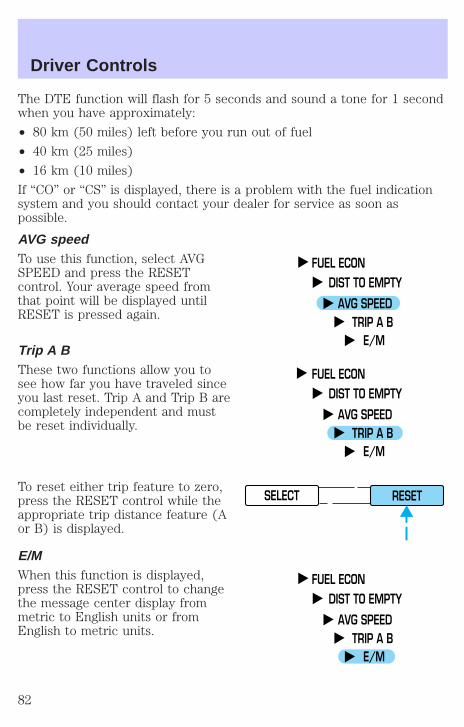
The DTE function will flash for 5 seconds and sound a tone for 1 secondwhen you have approximately:
• 80 km (50 miles) left before you run out of fuel
• 40 km (25 miles)
• 16 km (10 miles)
If “CO” or “CS” is displayed, there is a problem with the fuel indicationsystem and you should contact your dealer for service as soon aspossible.
AVG speedTo use this function, select AVGSPEED and press the RESETcontrol. Your average speed fromthat point will be displayed untilRESET is pressed again.
Trip A BThese two functions allow you tosee how far you have traveled sinceyou last reset. Trip A and Trip B arecompletely independent and mustbe reset individually.
To reset either trip feature to zero,press the RESET control while theappropriate trip distance feature (Aor B) is displayed.
E/MWhen this function is displayed,press the RESET control to changethe message center display frommetric to English units or fromEnglish to metric units.
FUEL ECON DIST TO EMPTY
AVG SPEEDTRIP A B
E/M
FUEL ECON DIST TO EMPTY
AVG SPEEDTRIP A B
E/M
SELECT RESET
FUEL ECON DIST TO EMPTY
AVG SPEEDTRIP A B
E/M
Driver Controls
82

OVERDRIVE CONTROL
Activating overdrive(Overdrive) is the normal drive position for the best fuel economy.
The overdrive function allows automatic upshifts and downshifts throughall available gears.
Deactivating overdrivePress the Transmission ControlSwitch (TCS) located on the end ofthe gearshift lever. TheTransmission Control Indicator Light(TCIL) will illuminate on theinstrument cluster. The transmission will operate in all gears exceptoverdrive.
To return to normal overdrive mode,press the Transmission ControlSwitch again. The TCIL will nolonger be illuminated.
When you shut off and re-start yourvehicle, the transmission will automatically return to normal(Overdrive) mode.
For additional information about the gearshift lever and the transmissioncontrol switch operation refer to the Automatic TransmissionOperation section of the Driving chapter.
TRUNK REMOTE CONTROLThe remote trunk release control islocated on the driver’s door trimpanel and can be operated at anytime.
You can render the switchinoperable by locking the buttonwith your master key.
O/DON/OFF
O/DON/OFF
TRUNK
Driver Controls
83
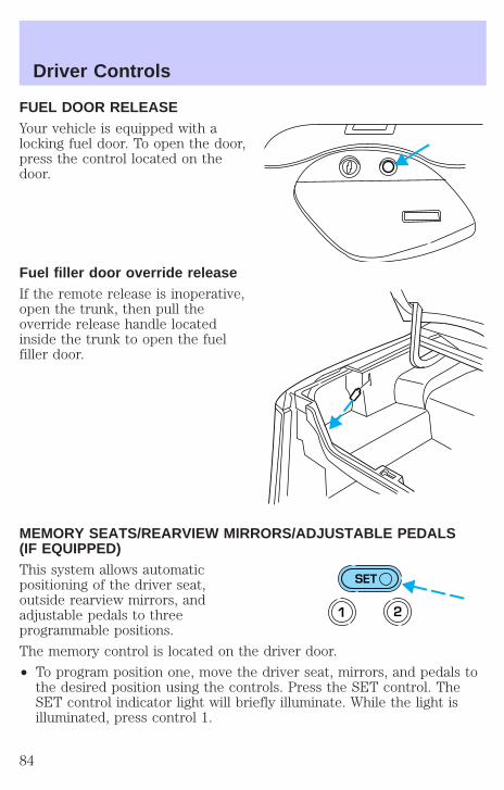
FUEL DOOR RELEASEYour vehicle is equipped with alocking fuel door. To open the door,press the control located on thedoor.
Fuel filler door override releaseIf the remote release is inoperative,open the trunk, then pull theoverride release handle locatedinside the trunk to open the fuelfiller door.
MEMORY SEATS/REARVIEW MIRRORS/ADJUSTABLE PEDALS(IF EQUIPPED)This system allows automaticpositioning of the driver seat,outside rearview mirrors, andadjustable pedals to threeprogrammable positions.
The memory control is located on the driver door.
• To program position one, move the driver seat, mirrors, and pedals tothe desired position using the controls. Press the SET control. TheSET control indicator light will briefly illuminate. While the light isilluminated, press control 1.
SET
1 2
Driver Controls
84
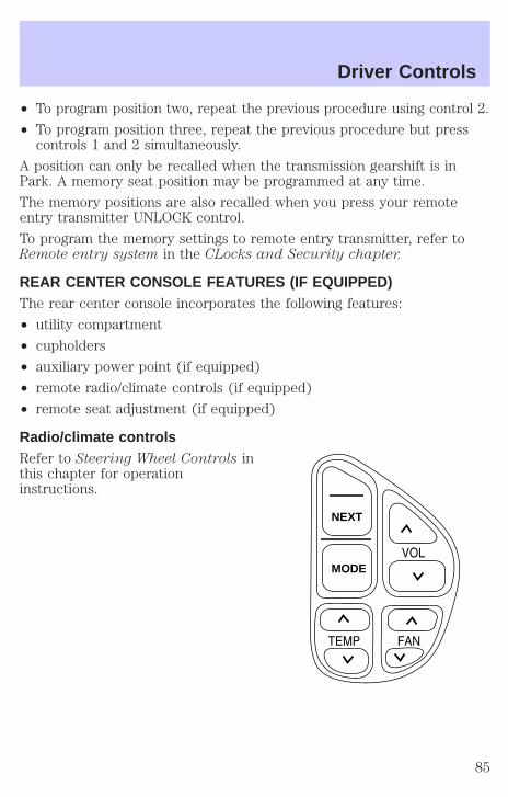
• To program position two, repeat the previous procedure using control 2.
• To program position three, repeat the previous procedure but presscontrols 1 and 2 simultaneously.
A position can only be recalled when the transmission gearshift is inPark. A memory seat position may be programmed at any time.
The memory positions are also recalled when you press your remoteentry transmitter UNLOCK control.
To program the memory settings to remote entry transmitter, refer toRemote entry system in the CLocks and Security chapter.
REAR CENTER CONSOLE FEATURES (IF EQUIPPED)The rear center console incorporates the following features:
• utility compartment
• cupholders
• auxiliary power point (if equipped)
• remote radio/climate controls (if equipped)
• remote seat adjustment (if equipped)
Radio/climate controlsRefer to Steering Wheel Controls inthis chapter for operationinstructions.
NEXT
MODE
Driver Controls
85
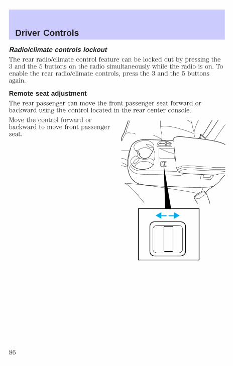
Radio/climate controls lockoutThe rear radio/climate control feature can be locked out by pressing the3 and the 5 buttons on the radio simultaneously while the radio is on. Toenable the rear radio/climate controls, press the 3 and the 5 buttonsagain.
Remote seat adjustmentThe rear passenger can move the front passenger seat forward orbackward using the control located in the rear center console.
Move the control forward orbackward to move front passengerseat.
Driver Controls
86
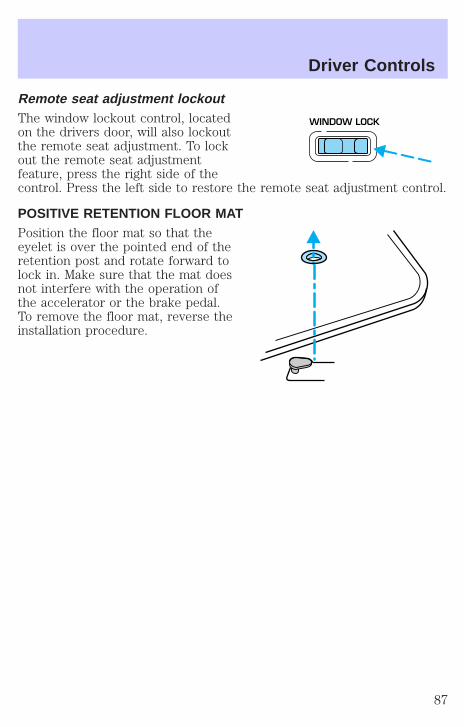
Remote seat adjustment lockoutThe window lockout control, locatedon the drivers door, will also lockoutthe remote seat adjustment. To lockout the remote seat adjustmentfeature, press the right side of thecontrol. Press the left side to restore the remote seat adjustment control.
POSITIVE RETENTION FLOOR MATPosition the floor mat so that theeyelet is over the pointed end of theretention post and rotate forward tolock in. Make sure that the mat doesnot interfere with the operation ofthe accelerator or the brake pedal.To remove the floor mat, reverse theinstallation procedure.
WINDOW LOCK
Driver Controls
87

KEYSThe vehicle is equipped with a master key and valet key lock system.The master key will access doors, trunk, glove box, ignition and remotetrunk release. The valet key (marked “valet”) will access doors andignition only. Before using this key, lock the trunk remote control todisable the Trunk remote control on the drivers door, then lock theglove compartment with your master key.
POWER DOOR LOCKSPress control to unlock or lock alldoors.
Smart locksWith the key in the ignition, in any switch position, and either thedriver’s or passenger’s door open, the doors cannot be locked using thepower door lock switches.
Childproof door locksWhen these locks are set, the reardoors cannot be opened from theinside. The rear doors can beopened from the outside when thedoors are unlocked.
The childproof locks are located onrear edge of each rear door andmust be set separately for eachdoor. Setting the lock for one doorwill not automatically set the lockfor both doors.
Move lock control up to engage thechildproof lock. Move control downto disengage childproof locks.
DOOR LOCK
LOCKEDVERROUILLEE
CHILD LOCK ABOVESECURITE ENFANTS
ENHAUT
Locks and Security
88

INTERIOR LUGGAGE COMPARTMENT RELEASEYour vehicle is equipped with a mechanical interior luggage compartmentrelease handle that provides a means of escape for children and adults inthe event they become locked inside the luggage compartment.
Adults are advised to familiarize themselves with the operation andlocation of the release handle.
To open the luggage compartmentdoor (lid) from the inside, pull theilluminated “T” shaped handle andpush up on the trunk lid. Thematerial that the handle is made ofwill glow for hours in the darknessof the luggage compartmentfollowing brief exposure to ambientlight.
The “T” shaped handle will belocated either on the luggagecompartment door (lid) or insidethe luggage compartment near thetail lamps.
Keep vehicle doors andluggage compartment
locked and keep keys out of achild’s reach. Unsupervisedchildren could lock themselves inan open trunk and risk injury.Children should be taught not toplay in vehicles.
On hot days, the temperature in the trunk or vehicle interior canrise very quickly. Exposure of people or animals to these high
temperatures for even a short time can cause death or seriousheat-related injuries, including brain damage. Small children areparticularly at risk.
Locks and Security
89
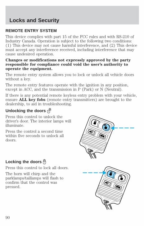
REMOTE ENTRY SYSTEMThis device complies with part 15 of the FCC rules and with RS-210 ofIndustry Canada. Operation is subject to the following two conditions:(1) This device may not cause harmful interference, and (2) This devicemust accept any interference received, including interference that maycause undesired operation.
Changes or modifications not expressly approved by the partyresponsible for compliance could void the user’s authority tooperate the equipment.
The remote entry system allows you to lock or unlock all vehicle doorswithout a key.
The remote entry features operate with the ignition in any position,except in ACC, and the transmission in P (Park) or N (Neutral).
If there is any potential remote keyless entry problem with your vehicle,ensure ALL key fobs (remote entry transmitters) are brought to thedealership, to aid in troubleshooting.
Unlocking the doorsPress this control to unlock thedriver’s door. The interior lamps willilluminate.
Press the control a second timewithin five seconds to unlock alldoors.
Locking the doorsPress this control to lock all doors.
The horn will chirp and theparklamps/taillamps will flash toconfirm that the control waspressed.
Locks and Security
90
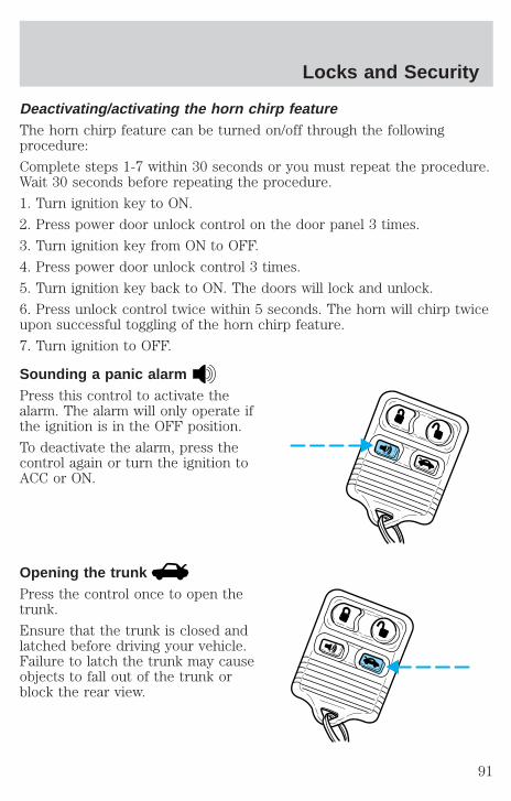
Deactivating/activating the horn chirp featureThe horn chirp feature can be turned on/off through the followingprocedure:
Complete steps 1-7 within 30 seconds or you must repeat the procedure.Wait 30 seconds before repeating the procedure.
1. Turn ignition key to ON.
2. Press power door unlock control on the door panel 3 times.
3. Turn ignition key from ON to OFF.
4. Press power door unlock control 3 times.
5. Turn ignition key back to ON. The doors will lock and unlock.
6. Press unlock control twice within 5 seconds. The horn will chirp twiceupon successful toggling of the horn chirp feature.
7. Turn ignition to OFF.
Sounding a panic alarmPress this control to activate thealarm. The alarm will only operate ifthe ignition is in the OFF position.
To deactivate the alarm, press thecontrol again or turn the ignition toACC or ON.
Opening the trunkPress the control once to open thetrunk.
Ensure that the trunk is closed andlatched before driving your vehicle.Failure to latch the trunk may causeobjects to fall out of the trunk orblock the rear view.
Locks and Security
91

The remote entry system allows you to open the trunk while the ignitionis in any position. However, if the ignition is in the ON position and thegearshift is in D (Drive), the trunk will only open if the vehicle is moving5 km/h (3 mph) or slower.
Replacing the batteryThe remote transmitter is powered by one coin type three-volt lithiumbattery CR2032 or equivalent. Typical operating range will allow you tobe up to 10 meters (33 feet) away from your vehicle. A decrease inoperating range can be caused by:
• weather conditions
• nearby radio towers
• structures around the vehicle
• other vehicles parked next to the vehicle
To replace the battery:
1. Twist a thin coin between the twohalves of the transmitter near thekey ring. DO NOT TAKE THEFRONT PART OF THETRANSMITTER APART.
2. Place the positive (+) side of newbattery in the same orientation.Refer to the diagram inside thetransmitter unit.
3. Snap the two halves backtogether.
Replacement of the battery will not cause the remote transmitter tobecome deprogrammed from your vehicle. The remote transmitter shouldoperate normally after battery replacement.
Locks and Security
92

Replacing lost transmittersTake all your vehicle’s transmittersto your dealer if service is required.
If a remote transmitter has been lostand you would like to remove itfrom the vehicle’s memory, or youwould like to purchase additionalremote transmitters and have themprogrammed to your vehicle:
• Take all your vehicle’stransmitters to your dealer forprogramming, or
• Perform the following programming procedure yourself
To reprogram the transmittersyourself, place the key in theignition and turn from 2 (LOCK) to3 (OFF) and cycle between 3 (OFF)and 4 (ON) four times in rapidsuccession within 3 seconds. Afterdoors lock/unlock, press any controlon all transmitters (up to four).When completed, turn the ignitionto 3 (OFF).
All transmitters must be programmed at the same time.
Illuminated entryThe interior lamps illuminate when the remote entry system is used tounlock the door(s) or sound the personal alarm.
The system automatically turns off after 25 seconds after the UNLOCKbutton on the remote transmitter is pressed or when the ignition isturned to the START or ACC position.
The inside lights will not turn off if:
• they have been turned on with the dimmer control or
• any door is open
The battery saver will shut off the interior lamps 30 minutes after thelast door is closed or after 10 minutes if the door is left open.
3
1
2
5
4
Locks and Security
93

AutolockThe autolock feature will lock all of the vehicle doors when:
• all doors are closed
• the engine is running and
• you shift into any gear putting the vehicle in motion
The autolock feature repeats when:
• any door, except the drivers door, is opened then closed while theengine is running and
• you put the vehicle in motion
Autolock can also be activated or deactivated using the followingprocedure:
You must complete steps 1 through 7 within 30 seconds or the procedurewill have to be repeated. If the procedure needs to be repeated, youmust wait 30 seconds.
1. Turn the ignition key to ON.
2. Press the power door unlock control on the door panel three times.
3. Turn the ignition key from ON to OFF.
4. Press the power door unlock control three times.
5. Turn the ignition key back to ON. The doors will lock and unlock.
6. Press the power door unlock control. The horn will chirp once uponsuccessful toggling of the Autolock feature.
7. Turn ignition to OFF.
Memory seat/mirrors/adjustable pedals feature (if equipped)The remote keyless entry system can also control theseat/mirrors/adjustable pedals feature. With this feature, the first twoprogrammed transmitters will recall a different memory position.
Locks and Security
94
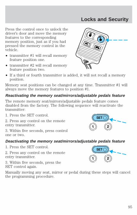
Press the control once to unlock thedriver’s door and move the memoryfeatures to the correspondingmemory position, just as if you hadpressed the memory control in thevehicle.
• transmitter #1 will recall memoryfeature position one.
• transmitter #2 will recall memoryfeature position two.
• If a third or fourth transmitter is added, it will not recall a memoryposition.
Memory seat positions can be changed at any time. Transmitter #1 willalways move the memory features to position #1.
Reactivating the memory seat/mirrors/adjustable pedals featureThe remote memory seat/mirrors/adjustable pedals feature comesdisabled from the factory. The following sequence will reactivate thetransmitter:
1. Press the SET control.
2. Press any control on the remoteentry transmitter.
3. Within five seconds, press controlone or two.
Deactivating the memory seat/mirrors/adjustable pedals feature1. Press the SET control.
2. Press any control on the remoteentry transmitter.
3. Within five seconds, press theSET control again.
Manually moving any seat, mirror or pedal during these steps will cancelthe programming procedure.
SET
1 2
SET
1 2
Locks and Security
95
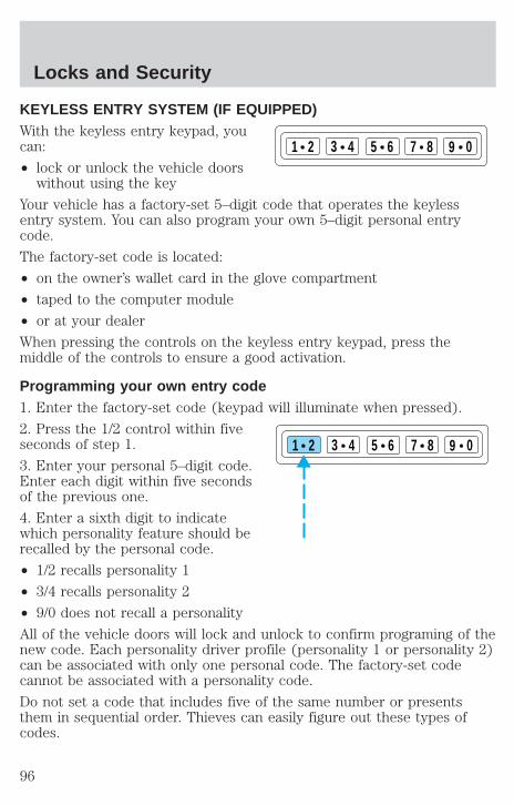
KEYLESS ENTRY SYSTEM (IF EQUIPPED)With the keyless entry keypad, youcan:
• lock or unlock the vehicle doorswithout using the key
Your vehicle has a factory-set 5–digit code that operates the keylessentry system. You can also program your own 5–digit personal entrycode.
The factory-set code is located:
• on the owner’s wallet card in the glove compartment
• taped to the computer module
• or at your dealer
When pressing the controls on the keyless entry keypad, press themiddle of the controls to ensure a good activation.
Programming your own entry code1. Enter the factory-set code (keypad will illuminate when pressed).
2. Press the 1/2 control within fiveseconds of step 1.
3. Enter your personal 5–digit code.Enter each digit within five secondsof the previous one.
4. Enter a sixth digit to indicatewhich personality feature should berecalled by the personal code.
• 1/2 recalls personality 1
• 3/4 recalls personality 2
• 9/0 does not recall a personality
All of the vehicle doors will lock and unlock to confirm programing of thenew code. Each personality driver profile (personality 1 or personality 2)can be associated with only one personal code. The factory-set codecannot be associated with a personality code.
Do not set a code that includes five of the same number or presentsthem in sequential order. Thieves can easily figure out these types ofcodes.
1 2 3 4 5 6 7 8 9 0
1 2 3 4 5 6 7 8 9 0
Locks and Security
96
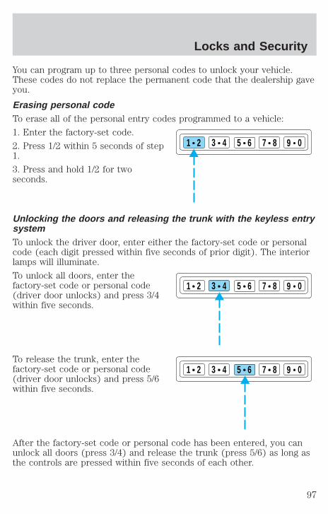
You can program up to three personal codes to unlock your vehicle.These codes do not replace the permanent code that the dealership gaveyou.
Erasing personal codeTo erase all of the personal entry codes programmed to a vehicle:
1. Enter the factory-set code.
2. Press 1/2 within 5 seconds of step1.
3. Press and hold 1/2 for twoseconds.
Unlocking the doors and releasing the trunk with the keyless entrysystemTo unlock the driver door, enter either the factory-set code or personalcode (each digit pressed within five seconds of prior digit). The interiorlamps will illuminate.
To unlock all doors, enter thefactory-set code or personal code(driver door unlocks) and press 3/4within five seconds.
To release the trunk, enter thefactory-set code or personal code(driver door unlocks) and press 5/6within five seconds.
After the factory-set code or personal code has been entered, you canunlock all doors (press 3/4) and release the trunk (press 5/6) as long asthe controls are pressed within five seconds of each other.
1 2 3 4 5 6 7 8 9 0
1 2 3 4 5 6 7 8 9 0
1 2 3 4 5 6 7 8 9 0
Locks and Security
97
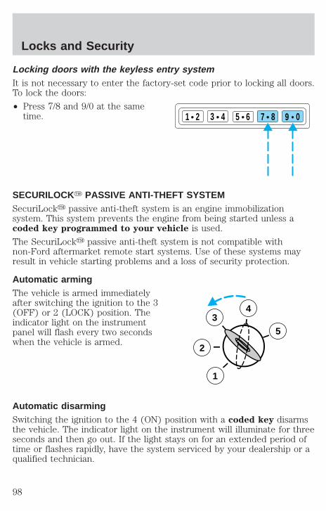
Locking doors with the keyless entry systemIt is not necessary to enter the factory-set code prior to locking all doors.To lock the doors:
• Press 7/8 and 9/0 at the sametime.
SECURILOCKY PASSIVE ANTI-THEFT SYSTEMSecuriLocky passive anti-theft system is an engine immobilizationsystem. This system prevents the engine from being started unless acoded key programmed to your vehicle is used.
The SecuriLocky passive anti-theft system is not compatible withnon-Ford aftermarket remote start systems. Use of these systems mayresult in vehicle starting problems and a loss of security protection.
Automatic armingThe vehicle is armed immediatelyafter switching the ignition to the 3(OFF) or 2 (LOCK) position. Theindicator light on the instrumentpanel will flash every two secondswhen the vehicle is armed.
Automatic disarmingSwitching the ignition to the 4 (ON) position with a coded key disarmsthe vehicle. The indicator light on the instrument will illuminate for threeseconds and then go out. If the light stays on for an extended period oftime or flashes rapidly, have the system serviced by your dealership or aqualified technician.
1 2 3 4 5 6 7 8 9 0
3
2
1
5
4
Locks and Security
98
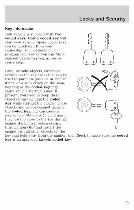
Key informationYour vehicle is supplied with twocoded keys. Only a coded key willstart your vehicle. Spare coded keyscan be purchased from yourdealership. Your dealership canprogram your key or you can “do ityourself”, refer to Programmingspare keys.
Large metallic objects, electronicdevices on the key chain that can beused to purchase gasoline or similaritems, or a second key on the samekey ring as the coded key maycause vehicle starting issues. Ifpresent, you need to keep theseobjects from touching the codedkey while starting the engine. Theseobjects and devices cannot damagethe coded key, but can cause amomentary NO—START condition ifthey are too close to the key duringengine start. If a problem occurs,turn ignition OFF and restart theengine with all other objects on thekey ring held away from the ignition key. Check to make sure the codedkey is an approved Lincoln coded key.
Locks and Security
99

If your keys are lost or stolen youwill need to do the following:
• Use your spare key to start thevehicle, or
• Have your vehicle towed to adealership or locksmith. The keycodes will need to be erased fromyour vehicle and new key codes will need to be re-coded.
Replacing coded keys can be very costly and you may want to store anextra programmed key away from the vehicle in a safe place to preventan unforeseen inconvenience.
The correct coded key must be used for your vehicle. The use of thewrong type of coded key may lead to a “NO-START” condition.
If an unprogrammed key is used in the ignition it will cause a“NO START” condition.
Programming spare keysA maximum of eight keys can be coded to your vehicle. OnlySecuriLocky keys can be used. To program a coded key yourself, youwill need two previously programmed coded keys (keys that alreadyoperate your vehicle’s engine) and the new unprogrammed key(s) readilyaccessible for timely implementation of each step in the procedure.
If two previously programmed coded keys are not available, you mustbring your vehicle to your dealership to have the spare coded key(s)programmed.
Locks and Security
100
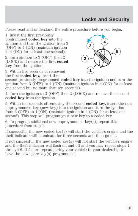
Please read and understand the entire procedure before you begin.
1. Insert the first previouslyprogrammed coded key into theignition and turn the ignition from 3(OFF) to 4 (ON) (maintain ignitionin 4 (ON) for at least one second).
2. Turn ignition to 3 (OFF) then 2(LOCK) and remove the first codedkey from the ignition.
3. Within five seconds of removingthe first coded key, insert thesecond previously programmed coded key into the ignition and turn theignition from 3 (OFF) to 4 (ON) (maintain ignition in 4 (ON) for at leastone second but no more than ten seconds).
4. Turn the ignition to 3 (OFF) then 2 (LOCK) and remove the secondcoded key from the ignition.
5. Within ten seconds of removing the second coded key, insert the newunprogrammed key (new key) into the ignition and turn the ignitionfrom 3 (OFF) to 4 (ON) (maintain ignition in 4 (ON) for at least onesecond). This step will program your new key to a coded key.
6. To program additional new unprogrammed key(s), repeat thisprocedure from step 1.
If successful, the new coded key(s) will start the vehicle’s engine and thetheft indicator will illuminate for three seconds and then go out.
If not successful, the new coded key(s) will not start the vehicle’s engineand the theft indicator will flash on and off and you may repeat steps 1through 6. If failure repeats, bring your vehicle to your dealership tohave the new spare key(s) programmed.
3
2
1
5
4
Locks and Security
101

SEATING
Head restraintsYour vehicle’s seats may be equipped with head restraints which arevertically adjustable. The purpose of these head restraints is to help limithead motion in the event of a rear collision. To properly adjust your headrestraints, lift the head restraint so that it is located directly behind yourhead or as close to that position as possible. Refer to the following toraise and lower the head restraints.
Push or pull the head rests to thedesired position.
Using the manual recline function (if equipped)
Never adjust the driver’s seat or seatback when the vehicle ismoving.
Do not pile cargo higher than the seatbacks to avoid injuringpeople in a collision or sudden stop.
Always drive and ride with your seatback upright and the lapbelt snug and low across the hips.
Reclining the seatback can reduce the effectiveness of the seat’ssafety belt in the event of a collision.
Seating and Safety Restraints
102
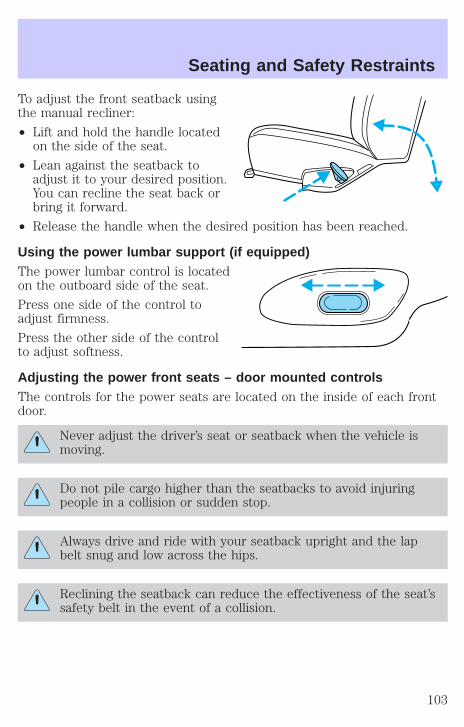
To adjust the front seatback usingthe manual recliner:
• Lift and hold the handle locatedon the side of the seat.
• Lean against the seatback toadjust it to your desired position.You can recline the seat back orbring it forward.
• Release the handle when the desired position has been reached.
Using the power lumbar support (if equipped)The power lumbar control is locatedon the outboard side of the seat.
Press one side of the control toadjust firmness.
Press the other side of the controlto adjust softness.
Adjusting the power front seats – door mounted controlsThe controls for the power seats are located on the inside of each frontdoor.
Never adjust the driver’s seat or seatback when the vehicle ismoving.
Do not pile cargo higher than the seatbacks to avoid injuringpeople in a collision or sudden stop.
Always drive and ride with your seatback upright and the lapbelt snug and low across the hips.
Reclining the seatback can reduce the effectiveness of the seat’ssafety belt in the event of a collision.
Seating and Safety Restraints
103

Press the control to recline theseatback forward or backward.
Press to move the seat forward orbackward.
Press to move the front portion ofthe seat cushion up or down.
Press to move the rear portion ofthe seat cushion up or down.
Seating and Safety Restraints
104
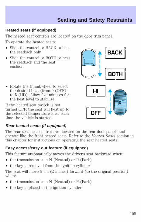
Heated seats (if equipped)The heated seat controls are located on the door trim panel.
To operate the heated seats:
• Slide the control to BACK to heatthe seatback only.
• Slide the control to BOTH to heatthe seatback and the seatcushion.
• Rotate the thumbwheel to selectthe desired heat (from 0 (OFF)to 5 (HI)). Allow five minutes forthe heat level to stabilize.
If the heated seat switch is notturned OFF, the seat will heat up tothe selected temperature level eachtime the vehicle is started.
Rear heated seats (if equipped)The rear seat heat controls are located on the rear door panels andoperate like the front heated seats. Refer to the Heated Seats section inthis chapter for instructions on operating the rear heated seats.
Easy access/easy out feature (if equipped)This feature automatically moves the driver’s seat backward when:
• the transmission is in N (Neutral) or P (Park)
• the key is removed from the ignition cylinder
The seat will move 5 cm (2 inches) forward (to the original position)when:
• the transmission is in N (Neutral) or P (Park)
• the key is placed in the ignition cylinder
BACK
BOTH
O
HI
OFF
Seating and Safety Restraints
105
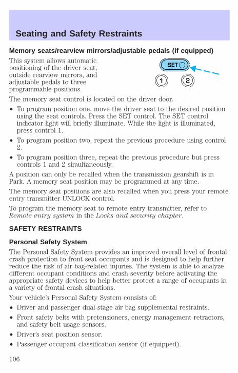
Memory seats/rearview mirrors/adjustable pedals (if equipped)This system allows automaticpositioning of the driver seat,outside rearview mirrors, andadjustable pedals to threeprogrammable positions.
The memory seat control is located on the driver door.
• To program position one, move the driver seat to the desired positionusing the seat controls. Press the SET control. The SET controlindicator light will briefly illuminate. While the light is illuminated,press control 1.
• To program position two, repeat the previous procedure using control2.
• To program position three, repeat the previous procedure but presscontrols 1 and 2 simultaneously.
A position can only be recalled when the transmission gearshift is inPark. A memory seat position may be programmed at any time.
The memory seat positions are also recalled when you press your remoteentry transmitter UNLOCK control.
To program the memory seat to remote entry transmitter, refer toRemote entry system in the Locks and security chapter.
SAFETY RESTRAINTS
Personal Safety SystemThe Personal Safety System provides an improved overall level of frontalcrash protection to front seat occupants and is designed to help furtherreduce the risk of air bag-related injuries. The system is able to analyzedifferent occupant conditions and crash severity before activating theappropriate safety devices to help better protect a range of occupants ina variety of frontal crash situations.
Your vehicle’s Personal Safety System consists of:
• Driver and passenger dual-stage air bag supplemental restraints.
• Front safety belts with pretensioners, energy management retractors,and safety belt usage sensors.
• Driver’s seat position sensor.
• Passenger occupant classification sensor (if equipped).
SET
1 2
Seating and Safety Restraints
106

• Front crash severity sensor.
• Restraints Control Module (RCM) with impact and safing sensors.
• Restraint system warning light and back-up tone.
• The electrical wiring for the air bags, crash sensor(s), safety beltpretensioners, front safety belt usage sensors, driver seat positionsensor, passenger occupant classification sensor (if equipped), andindicator lights.
How does the personal safety system work?The Personal safety system can adapt the deployment strategy of yourvehicle’s safety devices according to crash severity and occupantconditions. A collection of crash and occupant sensors providesinformation to the Restraints control module (RCM). During a crash, theRCM activates the safety belt pretensioners and/or either one or bothstages of the dual-stage air bag supplemental restraints based on crashseverity and occupant conditions.
The fact that the pretensioners or air bags did not activate for both frontseat occupants in a collision does not mean that something is wrong withthe system. Rather, it means the Personal safety system determined theaccident conditions (crash severity, belt usage, etc.) were notappropriate to activate these safety devices. Front air bags andpretensioners are designed to activate only in frontal and near-frontalcollisions, not rollovers, side-impacts, or rear-impacts unless the collisioncauses sufficient longitudinal deceleration.
Driver and passenger dual-stage air bag supplemental restraintsThe dual-stage air bags offer the capability to tailor the level of air baginflation energy. A lower, less forceful energy level is provided for morecommon, moderate-severity impacts. A higher energy level is used forthe most severe impacts. Refer to Air bag supplemental restraintssection in this chapter.
Front crash severity sensorThe front crash severity sensor enhances the ability to detect theseverity of an impact. Positioned up front, it provides valuableinformation early in the crash event on the severity of the impact. Thisallows your Personal safety system to distinguish between different levelsof crash severity and modify the deployment strategy of the dual-stageair bags and safety belt pretensioners.
Seating and Safety Restraints
107
Driver’s seat position sensorThe driver’s seat position sensor allows your Personal safety system totailor the deployment level of the driver dual-stage air bag based on seatposition. The system is designed to help protect smaller drivers sittingclose to the driver air bag by providing a lower air bag output level.
Passenger occupant classification sensor (OCS) (if equipped)If your vehicle is equipped with this feature, there will be a label locatedunder the front passenger seat which is marked “OCS”. Alternatively, youmay take your vehicle to any Ford or Lincoln Mercury dealer forassistance.
For air bags to do their job they must inflate with great force, and thisforce can pose a potentially deadly risk to occupants that are very closeto the air bag when it begins to inflate. For some occupants, like infantsin rear-facing child seats, this occurs because they are initially sittingvery close to the air bag. For other occupants, this occurs when theoccupant is not properly restrained by seat belts or child safety seats andthey move forward during pre-crash braking. The most effective way toreduce the risk of unnecessary injuries is to make sure all occupants areproperly restrained. Accident statistics suggest that children are muchsafer when properly restrained in the rear seating positions than in thefront.
Air bags can kill or injure a child in a child seat. NEVER place arear-facing child seat in front of an active air bag. If you must
use a forward-facing child seat in the front seat, move the seat all theway back.
Always transport children 12 years old and under in the backseat and always properly use appropriate child restraints.
The passenger occupant classification sensor can automatically turn offthe passenger front air bag and side air bag (if equipped). The system isdesigned to help protect small (child size) occupants from air bagdeployments when they are improperly seated or restrained in the frontpassenger seat contrary to proper child-seating or restraint usagerecommendations. Even with this technology, parents are STRONGLYencouraged to always properly restrain children in the rear seat. Thesensor also turns off the air bag(s) when the passenger seat is empty toprevent unnecessary replacement of the air bag(s) after a collision.
Seating and Safety Restraints
108

Front safety belt usage sensorsThe front safety belt usage sensors detect whether or not the driver andfront outboard passenger safety belts are fastened. This informationallows your Personal safety system to tailor the air bag deployment andsafety belt pretensioner activation depending upon safety belt usage.Refer to Safety belt section in this chapter.
Front safety belt pretensionersThe safety belt pretensioners are designed to tighten the safety beltsfirmly against the occupant’s body during a collision. This maximizes theeffectiveness of the safety belts and helps properly position the occupantrelative to the air bag to improve protection. The safety beltpretensioners can be either activated alone or, if the collision is ofsufficient severity, together with the air bags.
Front safety belt energy management retractorsThe front safety belt energy management retractors allow webbing to bepulled out of the retractor in a gradual and controlled manner inresponse to the occupant’s forward momentum. This helps reduce therisk of force-related injuries to the occupant’s chest by limiting the loadon the occupant. Refer to Safety belt section in this chapter.
Determining if the Personal safety system is operationalThe Personal safety system uses a warning light in the instrument clusteror a back-up tone to indicate the condition of the system. Refer to theWarning light section in the Instrument cluster chapter. Routinemaintenance of the Personal safety system is not required.
The Restraints control module (RCM) monitors its own internal circuitsand the circuits for the air bag supplemental restraints, crash sensor(s),safety belt pretensioners, front safety belt buckle sensors, driver seatposition sensor, and passenger occupant classification sensor (ifequipped). In addition, the RCM also monitors the restraints warninglight in the instrument cluster. A difficulty with the system is indicatedby one or more of the following.
• The warning light will either flash or stay lit.
• The warning light will not illuminate immediately after ignition isturned on.
• A series of five beeps will be heard. The tone pattern will repeatperiodically until the problem and warning light are repaired.
Seating and Safety Restraints
109
If any of these things happen, even intermittently, have the Personalsafety system serviced at your dealership or by a qualified technicianimmediately. Unless serviced, the system may not function properly inthe event of a collision.
Safety restraints precautions
Always drive and ride with your seatback upright and the lapbelt snug and low across the hips.
To reduce the risk of injury, make sure children sit where theycan be properly restrained.
Never let a passenger hold a child on his or her lap while thevehicle is moving. The passenger cannot protect the child from
injury in a collision.
All occupants of the vehicle, including the driver, should alwaysproperly wear their safety belts, even when an air bag (SRS) is
provided.
It is extremely dangerous to ride in a cargo area, inside oroutside of a vehicle. In a collision, people riding in these areas
are more likely to be seriously injured or killed. Do not allow people toride in any area of your vehicle that is not equipped with seats andsafety belts. Be sure everyone in your vehicle is in a seat and using asafety belt properly.
In a rollover crash, an unbelted person is significantly more likelyto die than a person wearing a safety belt.
Seating and Safety Restraints
110
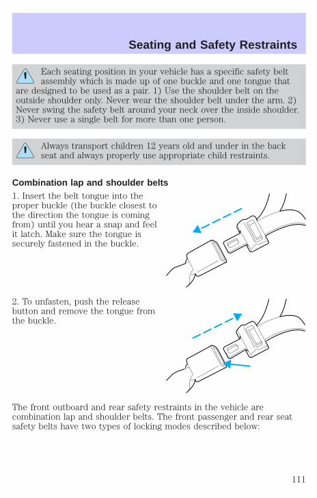
Each seating position in your vehicle has a specific safety beltassembly which is made up of one buckle and one tongue that
are designed to be used as a pair. 1) Use the shoulder belt on theoutside shoulder only. Never wear the shoulder belt under the arm. 2)Never swing the safety belt around your neck over the inside shoulder.3) Never use a single belt for more than one person.
Always transport children 12 years old and under in the backseat and always properly use appropriate child restraints.
Combination lap and shoulder belts1. Insert the belt tongue into theproper buckle (the buckle closest tothe direction the tongue is comingfrom) until you hear a snap and feelit latch. Make sure the tongue issecurely fastened in the buckle.
2. To unfasten, push the releasebutton and remove the tongue fromthe buckle.
The front outboard and rear safety restraints in the vehicle arecombination lap and shoulder belts. The front passenger and rear seatsafety belts have two types of locking modes described below:
Seating and Safety Restraints
111

Vehicle sensitive modeThe vehicle sensitive mode is the normal retractor mode, allowing freeshoulder belt length adjustment to your movements and locking inresponse to vehicle movement. For example, if the driver brakessuddenly or turns a corner sharply, or the vehicle receives an impact ofapproximately 8 km/h (5 mph) or more, the combination safety belts willlock to help reduce forward movement of the driver and passengers.
Automatic locking modeIn this mode, the shoulder belt is automatically pre-locked. The belt willstill retract to remove any slack in the shoulder belt.
The automatic locking mode is not available on the driver safety belt.
When to use the automatic locking mode• Any time a child safety seat is installed in the vehicle. Children 12
years old and under should be properly restrained in the rear seatwhenever possible. Refer to Safety restraints for children or Safetyseats for children later in this chapter.
How to use the automatic locking mode• Buckle the combination lap and
shoulder belt.
Seating and Safety Restraints
112

• Grasp the shoulder portion andpull downward until the entirebelt is extracted.
• Allow the belt to retract. As the belt retracts, you will hear a clickingsound. This indicates the safety belt is now in the automatic lockingmode.
How to disengage the automatic locking mode
Ford Motor Company recommends that all safety belt assembliesand attaching hardware should be inspected by a qualified
technician after any collision. Safety belt assemblies not in use during acollision should also be inspected and replaced if either damage orimproper operation is noted.
Disconnect the combination lap/shoulder belt and allow it to retractcompletely to disengage the automatic locking mode and activate thevehicle sensitive (emergency) locking mode.
After any vehicle collision, the seat belt system at all outboardseating positions (except driver, which has no “automatic locking
retractor” feature) must be checked by a qualified technician to verifythat the “automatic locking retractor” feature for child seats is stillfunctioning properly. In addition, all seat belts should be checked forproper function.
BELT AND RETRACTOR ASSEMBLY MUST BE REPLACED ifthe seat belt assembly “automatic locking retractor” feature or
any other seat belt function is not operating properly when checkedaccording to the procedures in Workshop Manual.
Seating and Safety Restraints
113
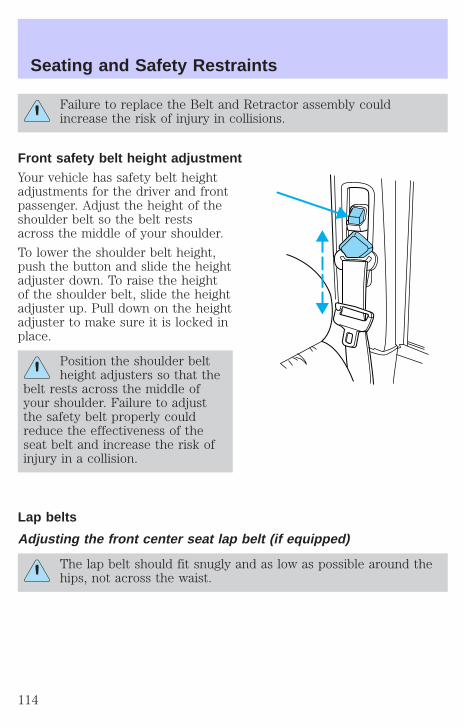
Failure to replace the Belt and Retractor assembly couldincrease the risk of injury in collisions.
Front safety belt height adjustmentYour vehicle has safety belt heightadjustments for the driver and frontpassenger. Adjust the height of theshoulder belt so the belt restsacross the middle of your shoulder.
To lower the shoulder belt height,push the button and slide the heightadjuster down. To raise the heightof the shoulder belt, slide the heightadjuster up. Pull down on the heightadjuster to make sure it is locked inplace.
Position the shoulder beltheight adjusters so that the
belt rests across the middle ofyour shoulder. Failure to adjustthe safety belt properly couldreduce the effectiveness of theseat belt and increase the risk ofinjury in a collision.
Lap belts
Adjusting the front center seat lap belt (if equipped)
The lap belt should fit snugly and as low as possible around thehips, not across the waist.
Seating and Safety Restraints
114
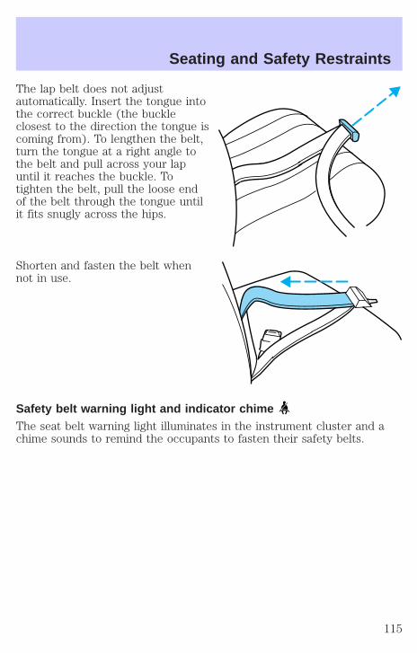
The lap belt does not adjustautomatically. Insert the tongue intothe correct buckle (the buckleclosest to the direction the tongue iscoming from). To lengthen the belt,turn the tongue at a right angle tothe belt and pull across your lapuntil it reaches the buckle. Totighten the belt, pull the loose endof the belt through the tongue untilit fits snugly across the hips.
Shorten and fasten the belt whennot in use.
Safety belt warning light and indicator chimeThe seat belt warning light illuminates in the instrument cluster and achime sounds to remind the occupants to fasten their safety belts.
Seating and Safety Restraints
115
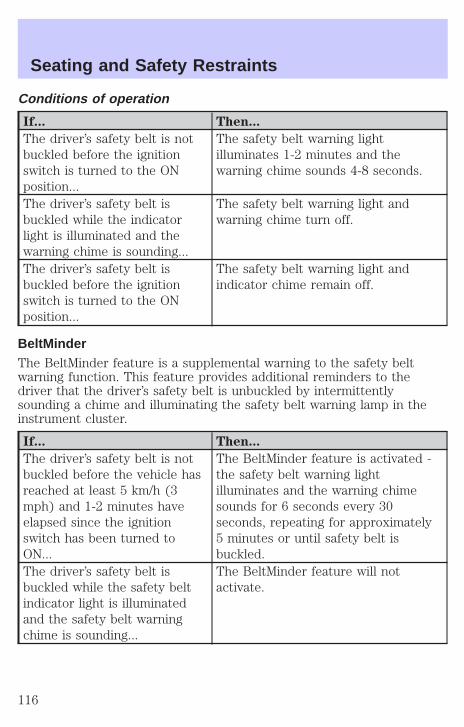
Conditions of operation
If... Then...
The driver’s safety belt is notbuckled before the ignitionswitch is turned to the ONposition...
The safety belt warning lightilluminates 1-2 minutes and thewarning chime sounds 4-8 seconds.
The driver’s safety belt isbuckled while the indicatorlight is illuminated and thewarning chime is sounding...
The safety belt warning light andwarning chime turn off.
The driver’s safety belt isbuckled before the ignitionswitch is turned to the ONposition...
The safety belt warning light andindicator chime remain off.
BeltMinderThe BeltMinder feature is a supplemental warning to the safety beltwarning function. This feature provides additional reminders to thedriver that the driver’s safety belt is unbuckled by intermittentlysounding a chime and illuminating the safety belt warning lamp in theinstrument cluster.
If... Then...
The driver’s safety belt is notbuckled before the vehicle hasreached at least 5 km/h (3mph) and 1-2 minutes haveelapsed since the ignitionswitch has been turned toON...
The BeltMinder feature is activated -the safety belt warning lightilluminates and the warning chimesounds for 6 seconds every 30seconds, repeating for approximately5 minutes or until safety belt isbuckled.
The driver’s safety belt isbuckled while the safety beltindicator light is illuminatedand the safety belt warningchime is sounding...
The BeltMinder feature will notactivate.
Seating and Safety Restraints
116
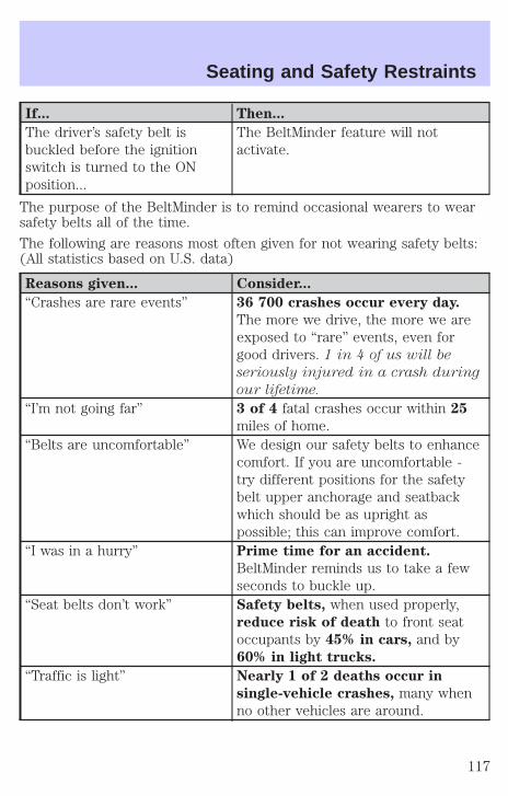
If... Then...
The driver’s safety belt isbuckled before the ignitionswitch is turned to the ONposition...
The BeltMinder feature will notactivate.
The purpose of the BeltMinder is to remind occasional wearers to wearsafety belts all of the time.
The following are reasons most often given for not wearing safety belts:(All statistics based on U.S. data)
Reasons given... Consider...
“Crashes are rare events” 36 700 crashes occur every day.
The more we drive, the more we areexposed to “rare” events, even forgood drivers. 1 in 4 of us will be
seriously injured in a crash during
our lifetime.
“I’m not going far” 3 of 4 fatal crashes occur within 25
miles of home.“Belts are uncomfortable” We design our safety belts to enhance
comfort. If you are uncomfortable -try different positions for the safetybelt upper anchorage and seatbackwhich should be as upright aspossible; this can improve comfort.
“I was in a hurry” Prime time for an accident.
BeltMinder reminds us to take a fewseconds to buckle up.
“Seat belts don’t work” Safety belts, when used properly,reduce risk of death to front seatoccupants by 45% in cars, and by60% in light trucks.
“Traffic is light” Nearly 1 of 2 deaths occur in
single-vehicle crashes, many whenno other vehicles are around.
Seating and Safety Restraints
117
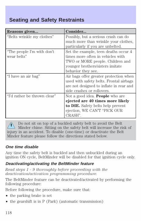
Reasons given... Consider...
“Belts wrinkle my clothes” Possibly, but a serious crash can domuch more than wrinkle your clothes,particularly if you are unbelted.
“The people I’m with don’twear belts”
Set the example, teen deaths occur 4times more often in vehicles withTWO or MORE people. Children andyounger brothers/sisters imitatebehavior they see.
“I have an air bag” Air bags offer greater protection whenused with safety belts. Frontal airbagsare not designed to inflate in rear andside crashes or rollovers.
“I’d rather be thrown clear” Not a good idea. People who areejected are 40 times more likely
to DIE. Safety belts help preventejection, WE CAN’T “PICK OURCRASH”.
Do not sit on top of a buckled safety belt to avoid the BeltMinder chime. Sitting on the safety belt will increase the risk of
injury in an accident. To disable (one-time) or deactivate the BeltMinder feature please follow the directions stated below.
One time disableAny time the safety belt is buckled and then unbuckled during anignition ON cycle, BeltMinder will be disabled for that ignition cycle only.
Deactivating/activating the BeltMinder featureRead steps 1 - 9 thoroughly before proceeding with thedeactivation/activation programming procedure.
The BeltMinder feature can be deactivated/activated by performing thefollowing procedure:
Before following the procedure, make sure that:
• the parking brake is set
• the gearshift is in P (Park) (automatic transmission)
Seating and Safety Restraints
118

• the ignition switch is in the OFF position
• all vehicle doors are closed
• the driver’s safety belt is unbuckled
• the parklamps/headlamps are in OFF position (If vehicle is equippedwith Autolamps, this will not affect the procedure.)
To reduce the risk of injury, do not deactivate/activate the BeltMinder feature while driving the vehicle.
1. Turn the ignition switch to the RUN (or ON) position. (DO NOTSTART THE ENGINE)
2. Wait until the safety belt warning light turns off. (Approximately 1–2minutes)
• Steps 3–5 must be completed within 60 seconds or the procedure willhave to be repeated.
3. Buckle then unbuckle the safety belt three times, ending with thesafety belt unbuckled. This can be done before or during BeltMinderwarning activation.
4. Turn on the parklamps/headlamps, turn off the parklamps/headlamps.
5. Buckle then unbuckle the safety belt three times, ending with thesafety belt unbuckled.
• After step 5 the safety belt warning light will be turned on for threeseconds.
6. Within seven seconds of the safety belt warning light turning off,buckle then unbuckle the safety belt.
• This will disable BeltMinder if it is currently enabled, or enableBeltMinder if it is currently disabled.
7. Confirmation of disabling BeltMinder is provided by flashing the safetybelt warning light four times per second for three seconds.
8. Confirmation of enabling BeltMinder is provided by flashing the safetybelt warning light four times per second for three seconds, followed bythree seconds with the safety belt warning light off, then followed byflashing the safety belt warning light four times per second for threeseconds again.
9. After receiving confirmation, the deactivation/activation procedure iscomplete.
Seating and Safety Restraints
119
Safety belt extension assemblyIf the safety belt is too short when fully extended, there is a 20 cm (8inch) safety belt extension assembly that can be added (part number611C22). This assembly can be obtained from your dealer at no cost.
Use only extensions manufactured by the same supplier as the safetybelt. Manufacturer identification is located at the end of the webbing onthe label. Also, use the safety belt extension only if the safety belt is tooshort for you when fully extended. Do not use extensions to change thefit of the shoulder belt across the torso.
Safety belt maintenanceInspect the safety belt systems periodically to make sure they workproperly and are not damaged. Inspect the safety belts to make surethere are no nicks, tears or cuts. Replace if necessary. All safety beltassemblies, including retractors, buckles, front seat belt buckleassemblies, buckle support assemblies (slide bar-if equipped), shoulderbelt height adjusters (if equipped), shoulder belt guide on seatback (ifequipped), child safety seat tether bracket assemblies (if equipped),LATCH child seat tether anchors and lower anchors (if equipped), andattaching hardware, should be inspected after a collision. Ford MotorCompany recommends that all safety belt assemblies used in vehiclesinvolved in a collision be replaced. However, if the collision was minorand a qualified technician finds that the belts do not show damage andcontinue to operate properly, they do not need to be replaced. Safetybelt assemblies not in use during a collision should also be inspected andreplaced if either damage or improper operation is noted.
Failure to inspect and if necessary replace the safety beltassembly under the above conditions could result in severe
personal injuries in the event of a collision.
Refer to Cleaning and maintaining the safety belts in the Cleaningchapter.
Seating and Safety Restraints
120
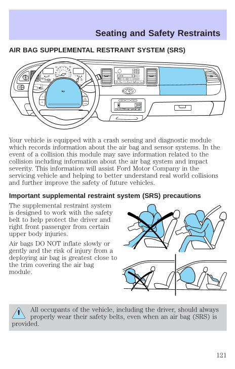
AIR BAG SUPPLEMENTAL RESTRAINT SYSTEM (SRS)
Your vehicle is equipped with a crash sensing and diagnostic modulewhich records information about the air bag and sensor systems. In theevent of a collision this module may save information related to thecollision including information about the air bag system and impactseverity. This information will assist Ford Motor Company in theservicing vehicle and helping to better understand real world collisionsand further improve the safety of future vehicles.
Important supplemental restraint system (SRS) precautionsThe supplemental restraint systemis designed to work with the safetybelt to help protect the driver andright front passenger from certainupper body injuries.
Air bags DO NOT inflate slowly orgently and the risk of injury from adeploying air bag is greatest close tothe trim covering the air bagmodule.
All occupants of the vehicle, including the driver, should alwaysproperly wear their safety belts, even when an air bag (SRS) is
provided.
OFFP 10
20
30
4050
60 70
80
90
100
120
20
60
80
40
100120
160
140
180
MPH km/h
110
H F
E
1 2
FILL ONLEFT
<
CHECKTRAC
SERVICEENGINESOON
PANELDIM
LOF
S
OFF
MIST
VOLPUSH ON
TAPE
MUTE SEEK TUNE
AM FMREW FF SIDE 1 2 COMP SHUFF
CD EJ RDS
SCAN AUTO
1 2 3 4 5 6
BASS
TREB
SEL
BAL
FADE
ON
OFF
RES
SETACCEL
COAST
EXT OFF MAXA/C
AUTO
FRONT
REAR
SELECT RESET
Seating and Safety Restraints
121

Always transport children 12 years old and under in the backseat and always properly use appropriate child restraints.
National Highway Traffic Safety Administration (NHTSA)recommends a minimum distance of at least 25 cm (10 inches)
between an occupant’s chest and the driver air bag module.
Never place your arm over the air bag module as a deploying airbag can result in serious arm fractures or other injuries.
Steps you can take to properly position yourself away from the air bag:
• Move your seat to the rear as far as you can while still reaching thepedals comfortably.
• Recline the seat slightly (one or two degrees) from the uprightposition.
Do not put anything on or over the air bag module. Placingobjects on or over the air bag inflation area may cause those
objects to be propelled by the air bag into your face and torso causingserious injury.
Do not attempt to service, repair, or modify the air bagsupplemental restraint systems or its fuses. See your Ford or
Lincoln Mercury dealer.
The front passenger air bag is not designed to offer protection tooccupants in the center front seating position.
Modifications to the front end of the vehicle, including frame,bumper, front end body structure and tow hooks may affect the
performance of the air bag sensors increasing the risk of injury. Do notmodify the front end of the vehicle.
Seating and Safety Restraints
122

Children and air bagsFor additional important safetyinformation, read all information onsafety restraints in this guide.
Children must always be properlyrestrained. Accident statisticssuggest that children are safer whenproperly restrained in the rearseating positions than in the frontseating position. Failure to followthese instructions may increase therisk of injury in a collision.
Air bags can kill or injure achild in a child seat.
NEVER place a rear-facing childseat in front of an active air bag. Ifyou must use a forward-facingchild seat in the front seat, movethe seat all the way back.
How does the air bag supplemental restraint system work?The air bag SRS is designed toactivate when the vehicle sustainslongitudinal deceleration sufficientto cause the sensors to close anelectrical circuit that initiates airbag inflation.
The fact that the air bags did notinflate in a collision does not meanthat something is wrong with thesystem. Rather, it means the forceswere not of the type sufficient tocause activation. Front air bags are designed to inflate in frontal andnear-frontal collisions, not rollover, side-impact, or rear-impacts unlessthe collision causes sufficient longitudinal deceleration.
Seating and Safety Restraints
123

The air bags inflate and deflaterapidly upon activation. After air bagdeployment, it is normal to notice asmoke-like, powdery residue orsmell the burnt propellant. This mayconsist of cornstarch, talcumpowder (to lubricate the bag) orsodium compounds (e.g., bakingsoda) that result from thecombustion process that inflates theair bag. Small amounts of sodiumhydroxide may be present whichmay irritate the skin and eyes, butnone of the residue is toxic.
While the system is designed to helpreduce serious injuries, contact witha deploying air bag may also cause abrasions, swelling or temporaryhearing loss. Because air bags must inflate rapidly and with considerableforce, there is the risk of death or serious injuries such as fractures,facial and eye injuries or internal injuries, particularly to occupants whoare not properly restrained or are otherwise out of position at the timeof air bag deployment. Thus, it is extremely important that occupants beproperly restrained as far away from the air bag module as possible whilemaintaining vehicle control.
Several air bag system components get hot after inflation. Do nottouch them after inflation.
If the air bag has deployed, the air bag will not functionagain and must be replaced immediately. If the air bag is not
replaced, the unrepaired area will increase the risk of injury in acollision.
The SRS consists of:
• driver and passenger air bag modules (which include the inflators andair bags).
• side air bags (if equipped). Refer to Side air bag system later in thischapter.
• one or more impact and safing sensors.
Seating and Safety Restraints
124

• a readiness light and tone.
• diagnostic module.
• and the electrical wiring which connects the components.
The diagnostic module monitors its own internal circuits and thesupplemental air bag electrical system warning (including the impactsensors), the system wiring, the air bag system readiness light, the airbag back up power and the air bag ignitors.
Determining if the system is operationalThe SRS uses a readiness light in the instrument cluster or a tone toindicate the condition of the system. Refer to Air bag readiness sectionin the Instrument cluster chapter. Routine maintenance of the air bag isnot required.
A difficulty with the system is indicated by one or more of the following:
• The readiness light will eitherflash or stay lit.
• The readiness light will notilluminate immediately afterignition is turned on.
• A series of five beeps will be heard. The tone pattern will repeatperiodically until the problem and/or light are repaired.
If any of these things happen, even intermittently, have the SRS servicedat your dealership or by a qualified technician immediately. Unlessserviced, the system may not function properly in the event of acollision.
Side air bag system (if equipped)
Do not place objects or mount equipment on or near the air bagcover on the side of the seatbacks of the front seats or in front
seat areas that may come into contact with a deploying air bag. Failureto follow these instructions may increase the risk of personal injury inthe event of a collision.
Do not use accessory seat covers. The use of accessory seatcovers may prevent the deployment of the side air bags and
increase the risk of injury in an accident.
AIRBAG
Seating and Safety Restraints
125
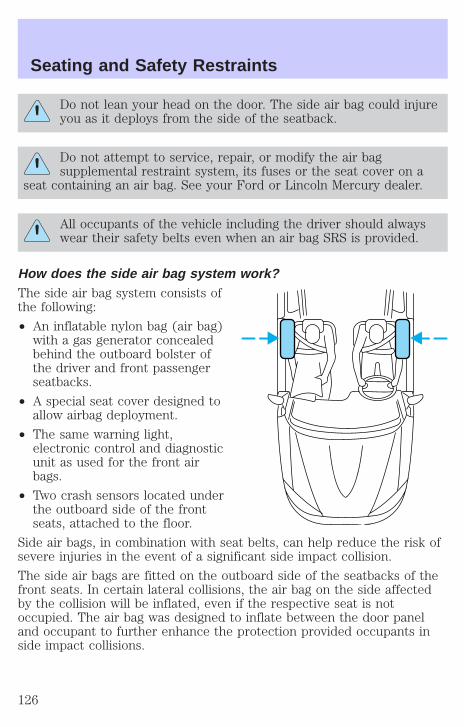
Do not lean your head on the door. The side air bag could injureyou as it deploys from the side of the seatback.
Do not attempt to service, repair, or modify the air bagsupplemental restraint system, its fuses or the seat cover on a
seat containing an air bag. See your Ford or Lincoln Mercury dealer.
All occupants of the vehicle including the driver should alwayswear their safety belts even when an air bag SRS is provided.
How does the side air bag system work?The side air bag system consists ofthe following:
• An inflatable nylon bag (air bag)with a gas generator concealedbehind the outboard bolster ofthe driver and front passengerseatbacks.
• A special seat cover designed toallow airbag deployment.
• The same warning light,electronic control and diagnosticunit as used for the front airbags.
• Two crash sensors located underthe outboard side of the frontseats, attached to the floor.
Side air bags, in combination with seat belts, can help reduce the risk ofsevere injuries in the event of a significant side impact collision.
The side air bags are fitted on the outboard side of the seatbacks of thefront seats. In certain lateral collisions, the air bag on the side affectedby the collision will be inflated, even if the respective seat is notoccupied. The air bag was designed to inflate between the door paneland occupant to further enhance the protection provided occupants inside impact collisions.
Seating and Safety Restraints
126
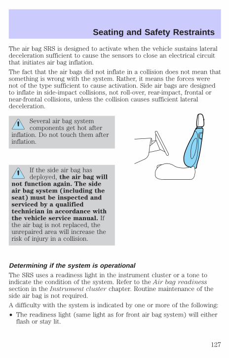
The air bag SRS is designed to activate when the vehicle sustains lateraldeceleration sufficient to cause the sensors to close an electrical circuitthat initiates air bag inflation.
The fact that the air bags did not inflate in a collision does not mean thatsomething is wrong with the system. Rather, it means the forces werenot of the type sufficient to cause activation. Side air bags are designedto inflate in side-impact collisions, not roll-over, rear-impact, frontal ornear-frontal collisions, unless the collision causes sufficient lateraldeceleration.
Several air bag systemcomponents get hot after
inflation. Do not touch them afterinflation.
If the side air bag hasdeployed, the air bag will
not function again. The sideair bag system (including theseat) must be inspected andserviced by a qualifiedtechnician in accordance withthe vehicle service manual. Ifthe air bag is not replaced, theunrepaired area will increase therisk of injury in a collision.
Determining if the system is operationalThe SRS uses a readiness light in the instrument cluster or a tone toindicate the condition of the system. Refer to the Air bag readinesssection in the Instrument cluster chapter. Routine maintenance of theside air bag is not required.
A difficulty with the system is indicated by one or more of the following:
• The readiness light (same light as for front air bag system) will eitherflash or stay lit.
Seating and Safety Restraints
127
• The readiness light will not illuminate immediately after ignition isturned on.
• A series of five beeps will be heard. The tone pattern will repeatperiodically until the problem and light are repaired.
If any of these things happen, even intermittently, have the SRS servicedat your dealership or by a qualified technician immediately. Unlessserviced, the system may not function properly in the event of acollision.
Disposal of air bags and air bag equipped vehicles (includingpretensioners)For disposal of air bags or air bag equipped vehicles, see your localdealership or qualified technician. Air bags MUST BE disposed of byqualified personnel.
SAFETY RESTRAINTS FOR CHILDRENSee the following sections for directions on how to properly use safetyrestraints for children. Also see Air bag supplemental restraint system(SRS) in this chapter for special instructions about using air bags.
Important child restraint precautionsYou are required by law to use safety restraints for children in the U.S.and Canada. If small children ride in your vehicle (generally children whoare four years old or younger and who weigh 18 kg [40 lbs] or less), youmust put them in safety seats made especially for children. Check yourlocal and state or provincial laws for specific requirements regarding thesafety of children in your vehicle.
Never let a passenger hold a child on his or her lap while thevehicle is moving. The passenger cannot protect the child from
injury in a collision.
Always follow the instructions and warnings that come with any infant orchild restraint you might use.
When possible, always place children under age 12 in the rear seat ofyour vehicle. Accident statistics suggest that children are safer whenproperly restrained in the rear seating positions than in the front seatingposition.
Seating and Safety Restraints
128
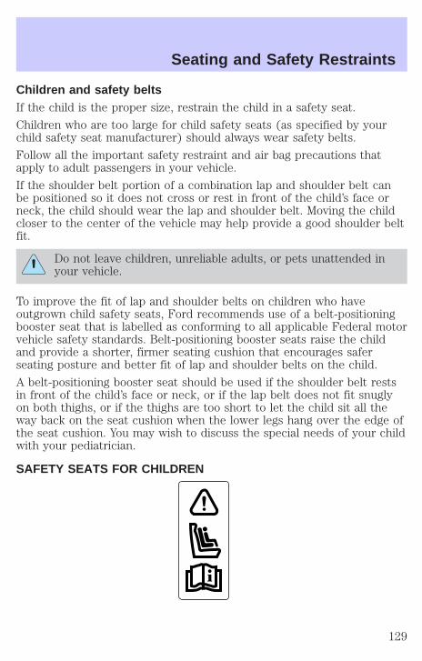
Children and safety beltsIf the child is the proper size, restrain the child in a safety seat.
Children who are too large for child safety seats (as specified by yourchild safety seat manufacturer) should always wear safety belts.
Follow all the important safety restraint and air bag precautions thatapply to adult passengers in your vehicle.
If the shoulder belt portion of a combination lap and shoulder belt canbe positioned so it does not cross or rest in front of the child’s face orneck, the child should wear the lap and shoulder belt. Moving the childcloser to the center of the vehicle may help provide a good shoulder beltfit.
Do not leave children, unreliable adults, or pets unattended inyour vehicle.
To improve the fit of lap and shoulder belts on children who haveoutgrown child safety seats, Ford recommends use of a belt-positioningbooster seat that is labelled as conforming to all applicable Federal motorvehicle safety standards. Belt-positioning booster seats raise the childand provide a shorter, firmer seating cushion that encourages saferseating posture and better fit of lap and shoulder belts on the child.
A belt-positioning booster seat should be used if the shoulder belt restsin front of the child’s face or neck, or if the lap belt does not fit snuglyon both thighs, or if the thighs are too short to let the child sit all theway back on the seat cushion when the lower legs hang over the edge ofthe seat cushion. You may wish to discuss the special needs of your childwith your pediatrician.
SAFETY SEATS FOR CHILDREN
Seating and Safety Restraints
129

Child and infant or child safety seatsUse a safety seat that is recommended for the size and weight of thechild. Carefully follow all of the manufacturer’s instructions with thesafety seat you put in your vehicle. If you do not install and use thesafety seat properly, the child may be injured in a sudden stop orcollision.
When installing a child safety seat:
• Review and follow the informationpresented in the Air BagSupplemental Restraint Systemsection in this chapter.
• Use the correct safety belt bucklefor that seating position.
• Insert the belt tongue into theproper buckle until you hear asnap and feel it latch. Make surethe tongue is securely fastened inthe buckle.
• Keep the buckle release buttonpointing up and away from thesafety seat, with the tonguebetween the child seat and therelease button, to preventaccidental unbuckling.
• Place seat back in upright position.
• Put the safety belt in the automatic locking mode. Refer to Automaticlocking mode.
Ford recommends the use of a child safety seat having a top tetherstrap. Install the child safety seat in a seating position which is capableof providing a tether anchorage. For more information on top tetherstraps, refer to Attaching safety seats with tether straps in this chapter.
Carefully follow all of the manufacturer’s instructions includedwith the safety seat you put in your vehicle. If you do not install
and use the safety seat properly, the child may be injured in a suddenstop or collision.
Seating and Safety Restraints
130
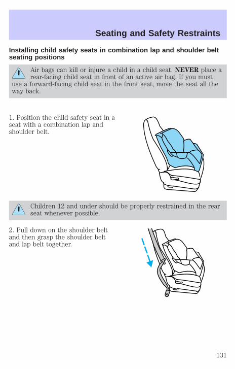
Installing child safety seats in combination lap and shoulder beltseating positions
Air bags can kill or injure a child in a child seat. NEVER place arear-facing child seat in front of an active air bag. If you must
use a forward-facing child seat in the front seat, move the seat all theway back.
1. Position the child safety seat in aseat with a combination lap andshoulder belt.
Children 12 and under should be properly restrained in the rearseat whenever possible.
2. Pull down on the shoulder beltand then grasp the shoulder beltand lap belt together.
Seating and Safety Restraints
131

3. While holding the shoulder andlap belt portions together, route thetongue through the child seataccording to the child seatmanufacturer’s instructions. Be surethe belt webbing is not twisted.
4. Insert the belt tongue into theproper buckle (the buckle closest tothe direction the tongue is comingfrom) for that seating position untilyou hear a snap and feel the latchengage. Make sure the tongue islatched securely by pulling on it.
5. To put the retractor in theautomatic locking mode, grasp theshoulder portion of the belt and pulldownward until all of the belt isextracted and a click is heard.
6. Allow the belt to retract. The belt will click as it retracts to indicate itis in the automatic locking mode.
Seating and Safety Restraints
132

7. Pull the lap belt portion acrossthe child seat toward the buckle andpull up on the shoulder belt whilepushing down with your knee on thechild seat.
8. Allow the safety belt to retract toremove any slack in the belt.
9. Before placing the child in theseat, forcibly tilt the seat forwardand back to make sure the seat issecurely held in place. To checkthis, grab the seat at the belt pathand attempt to move it side to sideand forward and back. There shouldbe no more than one inch ofmovement for proper installation.
10. Try to pull the belt out of the retractor to make sure the retractor isin the automatic locking mode (you should not be able to pull more beltout). If the retractor is not locked, unbuckle the belt and repeat stepstwo through nine.
Check to make sure the child seat is properly secured before each use.
Attaching child safety seats with tether strapsMost new forward-facing child safety seats include a tether strap whichgoes over the back of the seat and hooks to an anchoring point. Tetherstraps are available as an accessory for many older safety seats. Contactthe manufacturer of your child seat for information about ordering atether strap.
The rear seats of your vehicle are equipped with built-in tether strapanchors located behind the seats as described below.
The tether anchors in your vehicle are located under a cover markedwith the tether anchor symbol (shown with title).
Seating and Safety Restraints
133

The tether strap anchors in yourvehicle are in the following positions(shown from top view):
Attach the tether strap only to the appropriate tether anchor asshown. The tether strap may not work properly if attached
somewhere other than the correct tether anchor.
1. Position the child safety seat on the seat cushion.
2. Route the child safety seat tether strap over the back of the seat.
For vehicles with adjustable head restraints, route the tether strap underthe head restraint and between the head restraint posts, otherwise routethe tether strap over the top of the seatback.
3. Locate the correct anchor for theselected seating position.
4. Open the tether anchor cover.
Seating and Safety Restraints
134
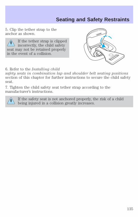
5. Clip the tether strap to theanchor as shown.
If the tether strap is clippedincorrectly, the child safety
seat may not be retained properlyin the event of a collision.
6. Refer to the Installing childsafety seats in combination lap and shoulder belt seating positionssection of this chapter for further instructions to secure the child safetyseat.
7. Tighten the child safety seat tether strap according to themanufacturer’s instructions.
If the safety seat is not anchored properly, the risk of a childbeing injured in a collision greatly increases.
Seating and Safety Restraints
135
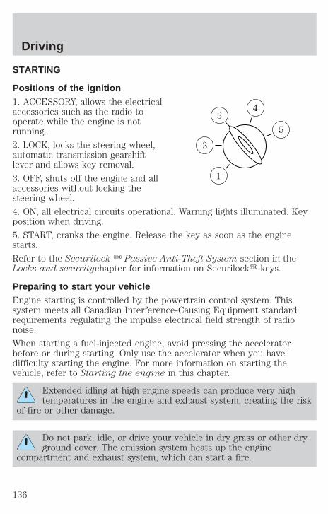
STARTING
Positions of the ignition1. ACCESSORY, allows the electricalaccessories such as the radio tooperate while the engine is notrunning.
2. LOCK, locks the steering wheel,automatic transmission gearshiftlever and allows key removal.
3. OFF, shuts off the engine and allaccessories without locking thesteering wheel.
4. ON, all electrical circuits operational. Warning lights illuminated. Keyposition when driving.
5. START, cranks the engine. Release the key as soon as the enginestarts.
Refer to the Securilock y Passive Anti-Theft System section in theLocks and securitychapter for information on Securilocky keys.
Preparing to start your vehicleEngine starting is controlled by the powertrain control system. Thissystem meets all Canadian Interference-Causing Equipment standardrequirements regulating the impulse electrical field strength of radionoise.
When starting a fuel-injected engine, avoid pressing the acceleratorbefore or during starting. Only use the accelerator when you havedifficulty starting the engine. For more information on starting thevehicle, refer to Starting the engine in this chapter.
Extended idling at high engine speeds can produce very hightemperatures in the engine and exhaust system, creating the risk
of fire or other damage.
Do not park, idle, or drive your vehicle in dry grass or other dryground cover. The emission system heats up the engine
compartment and exhaust system, which can start a fire.
3
1
2
5
4
Driving
136

Do not start your vehicle in a closed garage or in other enclosedareas. Exhaust fumes can be toxic. Always open the garage door
before you start the engine. See Guarding against exhaust fumes inthis chapter for more instructions.
If you smell exhaust fumes inside your vehicle, have your dealerinspect your vehicle immediately. Do not drive if you smell
exhaust fumes.
Important safety precautionsA computer system controls the engine’s idle revolutions per minute(RPM). When the engine starts, the idle RPM runs faster to warm theengine. If the engine idle speed does not slow down automatically, havethe vehicle checked. Do not allow the vehicle to idle for more than 10minutes at the higher engine RPM.
Before starting the vehicle:
1. Make sure all vehicle occupants have buckled their safety belts. Formore information on safety belts and their proper usage, refer to theSeating and safety restraints chapter.
2. Make sure the headlamps and vehicle accessories are off.
3. Make sure the gearshift is in P(Park).
4. Make sure the parking brake isset.
HOOD
Driving
137

5. Turn the key to 4 (ON) withoutturning the key to 5 (START).
If there is difficulty in turning thekey, firmly rotate the steering wheelleft and right until the key turnsfreely. This condition may occurwhen:
• front wheels are turned
• front wheel is against the curb
• steering wheel is turned when getting in or out of the vehicle
Make sure the corresponding lights illuminate or illuminate briefly. If alight fails to illuminate, have the vehicle serviced.
• If the driver’s safety belt is fastened, the light may not illuminate.
Starting the engineNote: Whenever you start your vehicle, release the key as soon as theengine starts. Excessive cranking could damage the starter.
1
2
34
5
10
20
30
4050
60 70
80
90
100
120
20
60
80
40
100120
160
140
180
P R N D 2 1
MPH km/h
110
H F
E
1 2
FILL ONLEFT
<
AIRBAG
SERVICEENGINESOON
TRUNK AJAR DOOR AJARTRAC OFF AIR SUSPENSION
O/D OFF TRAC ACTIVESPEED CONTROL COMPASS
km
CIRCLE SLOWLY
FUEL ECON DIST TO EMPTY
AVG SPEEDTRIP A B
E/Mkm MILES/GAL
WASHER LTR/100km
BRAKE
CHECKFUELCAP
Driving
138
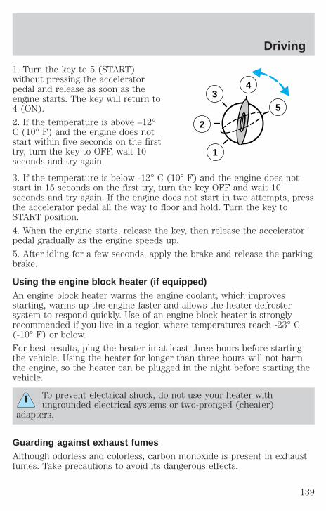
1. Turn the key to 5 (START)without pressing the acceleratorpedal and release as soon as theengine starts. The key will return to4 (ON).
2. If the temperature is above –12°C (10° F) and the engine does notstart within five seconds on the firsttry, turn the key to OFF, wait 10seconds and try again.
3. If the temperature is below -12° C (10° F) and the engine does notstart in 15 seconds on the first try, turn the key OFF and wait 10seconds and try again. If the engine does not start in two attempts, pressthe accelerator pedal all the way to floor and hold. Turn the key toSTART position.
4. When the engine starts, release the key, then release the acceleratorpedal gradually as the engine speeds up.
5. After idling for a few seconds, apply the brake and release the parkingbrake.
Using the engine block heater (if equipped)An engine block heater warms the engine coolant, which improvesstarting, warms up the engine faster and allows the heater-defrostersystem to respond quickly. Use of an engine block heater is stronglyrecommended if you live in a region where temperatures reach -23° C(-10° F) or below.
For best results, plug the heater in at least three hours before startingthe vehicle. Using the heater for longer than three hours will not harmthe engine, so the heater can be plugged in the night before starting thevehicle.
To prevent electrical shock, do not use your heater withungrounded electrical systems or two-pronged (cheater)
adapters.
Guarding against exhaust fumesAlthough odorless and colorless, carbon monoxide is present in exhaustfumes. Take precautions to avoid its dangerous effects.
3
2
1
5
4
Driving
139
If you ever smell exhaust fumes of any kind inside your vehicle,have your dealer inspect and fix your vehicle immediately. Do
not drive if you smell exhaust fumes. These fumes are harmful andcould kill you.
Have the exhaust and body ventilation systems checked whenever:
• the vehicle is raised for service
• the sound of the exhaust system changes
• the vehicle has been damaged in a collision
WARNING: Engine exhaust, some of its constituents, andcertain vehicle components contain or emit chemicals known to
the State of California to cause cancer and birth defects or otherreproductive harm. In addition, certain fluids contained in vehicles andcertain products of component wear contain or emit chemicals knownto the State of California to cause cancer and birth defects or otherreproductive harm.
Important ventilating informationIf the engine is idling while the vehicle is stopped in an open area forlong periods of time, open the windows at least 2.5 cm (one inch).
Adjust the heating or air conditioning (if equipped) to bring in fresh air.
Improve vehicle ventilation by keeping all air inlet vents clear of snow,leaves and other debris.
BRAKESYour service brakes are self-adjusting. Refer to the scheduledmaintenance guide for scheduled maintenance.
Occasional brake noise is normal and often does not indicate aperformance concern with the vehicle’s brake system. In normal operation,automotive brake systems may emit occasional or intermittent squeal orgroan noises when the brakes are applied. Such noises are usually heardduring the first few brake applications in the morning; however, they maybe heard at any time while braking and can be aggravated byenvironmental conditions such as cold, heat, moisture, road dust, salt ormud. If a “metal-to-metal,” “continuous grinding” or “continuous squeal”sound is present while braking, the brake linings may be worn-out andshould be inspected by a qualified service technician.
Driving
140
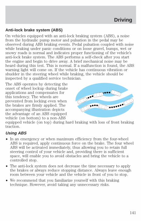
Anti-lock brake system (ABS)On vehicles equipped with an anti-lock braking system (ABS), a noisefrom the hydraulic pump motor and pulsation in the pedal may beobserved during ABS braking events. Pedal pulsation coupled with noisewhile braking under panic conditions or on loose gravel, bumps, wet orsnowy roads is normal and indicates proper functioning of the vehicle’santi-lock brake system. The ABS performs a self-check after you startthe engine and begin to drive away. A brief mechanical noise may beheard during this test. This is normal. If a malfunction is found, the ABSwarning light will come on. If the vehicle has continuous vibration orshudder in the steering wheel while braking, the vehicle should beinspected by a qualified service technician.
The ABS operates by detecting theonset of wheel lockup during brakeapplications and compensates forthis tendency. The wheels areprevented from locking even whenthe brakes are firmly applied. Theaccompanying illustration depictsthe advantage of an ABS equippedvehicle (on bottom) to a non-ABSequipped vehicle (on top) during hard braking with loss of front brakingtraction.
Using ABS• In an emergency or when maximum efficiency from the four-wheel
ABS is required, apply continuous force on the brake. The four wheelABS will be activated immediately, thus allowing you to retain fullsteering control of your vehicle and, providing there is sufficientspace, will enable you to avoid obstacles and bring the vehicle to acontrolled stop.
• The anti-lock system does not decrease the time necessary to applythe brakes or always reduce stopping distance. Always leave enoughroom between your vehicle and the vehicle in front of you to stop.
• We recommend that you familiarize yourself with this brakingtechnique. However, avoid taking any unnecessary risks.
Driving
141
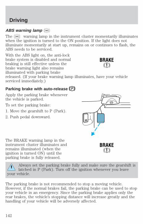
ABS warning lamp ABS
The ABS warning lamp in the instrument cluster momentarily illuminateswhen the ignition is turned to the ON position. If the light does notilluminate momentarily at start up, remains on or continues to flash, theABS needs to be serviced.
With the ABS light on, the anti-lockbrake system is disabled and normalbraking is still effective unless thebrake warning light also remainsilluminated with parking brakereleased. (If your brake warning lamp illuminates, have your vehicleserviced immediately.)
Parking brake with auto-releaseApply the parking brake wheneverthe vehicle is parked.
To set the parking brake:
1. Move the gearshift to P (Park).
2. Push pedal downward.
The BRAKE warning lamp in theinstrument cluster illuminates andremains illuminated (when theignition is turned ON) until theparking brake is fully released.
Always set the parking brake fully and make sure the gearshift islatched in P (Park). Turn off the ignition whenever you leave
your vehicle.
The parking brake is not recommended to stop a moving vehicle.However, if the normal brakes fail, the parking brake can be used to stopyour vehicle in an emergency. Since the parking brake applies only therear brakes, the vehicle’s stopping distance will increase greatly and thehandling of your vehicle will be adversely affected.
!BRAKE
HOOD
!BRAKE
Driving
142

Your vehicle has an automatic parking brake release. To release theparking brake:
1. Turn the ignition to the ON position.
2. Press the brake pedal.
3. Move the gearshift from the P (Park) position to one of the forwardgears (the parking brake will not release automatically when you shiftinto reverse). The brake pedal must remain pressed while the gearshift ismoved.
If the parking brake fails to releaseafter completing this procedure, usethe manual parking brake releaselever.
Pull the lever to manually releasethe parking brake.
TRACTION CONTROLY
For Traction Controly warning lights refer to Warning Lights in theInstrumentationchapter.
Your vehicle may be equipped with the optional Traction Controlysystem. This system helps you maintain the stability and steerability ofyour vehicle. It is especially useful on slippery and/or hilly road surfaces.The system operates by detecting and controlling wheel spin. The systemborrows many of the electronic and mechanical elements already presentin the anti-lock braking system (ABS).
Wheel-speed sensors allow excess rear wheel spin to be detected by theTraction Controly portion of the ABS computer. Any excessive wheelspin is controlled by automatically applying and releasing the rear brakesin conjunction with engine torque reductions. Engine torque reduction isrealized via the fully electronic spark and fuel injection systems. Thisprocess is very sensitive to driving conditions and very fast acting. Therear wheels “search” for optimum traction several times a second andadjustments are made accordingly.
HOOD
Driving
143

The Traction Controly system will allow your vehicle to make better useof available traction on slippery surfaces. The system is a driver aidwhich makes your vehicle easier to handle primarily on snow and icecovered roads.
During Traction Controly operation you may hear an electric motor typeof sound coming from the engine compartment and the engine will not“rev-up” when you push further on the accelerator. This is normalsystem behavior.
If you should become stuck in snowor ice or on a very slippery roadsurface, try switching the TractionControly system off. This may allowexcess wheel spin to “dig” thevehicle out and enable a successful“rocking” maneuver.
Traction control switchThe traction control switch is located on the left side of the instrumentpanel. The traction control system defaults to ON when the ignition keyis turned from OFF to RUN.
STEERINGYour vehicle is equipped with power steering. Power steering uses energyfrom the engine to help steer the vehicle.
To prevent damage to the power steering pump:
• Never hold the steering wheel to the extreme right or the extreme leftfor more than a few seconds when the engine is running.
• Do not operate the vehicle with a low power steering pump fluid level(below the MIN mark on the reservoir).
If the power steering system breaks down (or if the engine is turnedoff), you can steer the vehicle manually, but it takes more effort.
If the steering wanders or pulls, the condition could be caused by any ofthe following:
• underinflated tire(s) on any wheel(s)
• uneven vehicle loading
• high crown in center of road
Driving
144
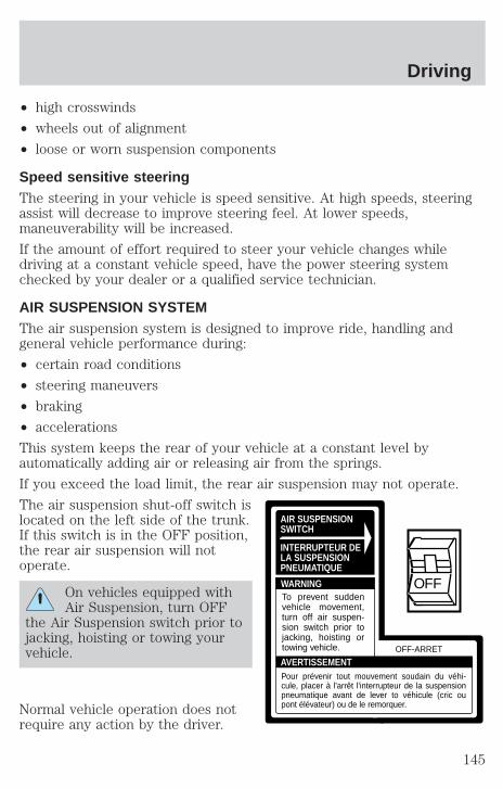
• high crosswinds
• wheels out of alignment
• loose or worn suspension components
Speed sensitive steeringThe steering in your vehicle is speed sensitive. At high speeds, steeringassist will decrease to improve steering feel. At lower speeds,maneuverability will be increased.
If the amount of effort required to steer your vehicle changes whiledriving at a constant vehicle speed, have the power steering systemchecked by your dealer or a qualified service technician.
AIR SUSPENSION SYSTEMThe air suspension system is designed to improve ride, handling andgeneral vehicle performance during:
• certain road conditions
• steering maneuvers
• braking
• accelerations
This system keeps the rear of your vehicle at a constant level byautomatically adding air or releasing air from the springs.
If you exceed the load limit, the rear air suspension may not operate.
The air suspension shut-off switch islocated on the left side of the trunk.If this switch is in the OFF position,the rear air suspension will notoperate.
On vehicles equipped withAir Suspension, turn OFF
the Air Suspension switch prior tojacking, hoisting or towing yourvehicle.
Normal vehicle operation does notrequire any action by the driver.
AIR SUSPENSIONSWITCH
INTERRUPTEUR DELA SUSPENSIONPNEUMATIQUE
WARNING
AVERTISSEMENTOFF-ARRET
To prevent sudden vehicle movement, turn off air suspen-sion switch prior to jacking, hoisting or towing vehicle.
Pour prévenir tout mouvement soudain du véhi-cule, placer à l'arrêt l'interrupteur de la suspension pneumatique avant de lever to véhicule (cric ou pont élévateur) ou de le remorquer.
OFF
Driving
145

AUTOMATIC TRANSMISSION OPERATION (IF EQUIPPED)
Brake-shift interlockThis vehicle is equipped with a brake-shift interlock feature that preventsthe gearshift lever from being moved from P (Park) when the ignition isin the ON position unless the brake pedal is depressed.
If you cannot move the gearshift lever out of P (Park) with ignition inthe ON position and the brake pedal depressed:
1. Apply the parking brake, turn ignition key to LOCK, then remove thekey.
2. Insert the key and turn it to OFF. Apply the brake pedal and shiftto N (Neutral).
3. Start the vehicle.
If it is necessary to use the above procedure to move the gearshift lever,it is possible that a fuse has blown or the vehicle’s brakelamps are notoperating properly. Refer to Fuses and relays in the Roadsideemergencies chapter.
Do not drive your vehicle until you verify that the brakelampsare working.
If your vehicle gets stuck in mud or snow it may be rocked out byshifting from forward and reverse gears, stopping between shifts, in asteady pattern. Press lightly on the accelerator in each gear.
Do not rock the vehicle if the engine is not at normal operatingtemperature or damage to the transmission may occur.
Do not rock the vehicle for more than a few minutes or damageto the transmission and tires may occur or the engine mayoverheat.
Always set the parking brake fully and make sure the gearshift islatched in P (Park). Turn off the ignition whenever you leave
your vehicle.
If the parking brake is fully released, but the brake warning lampremains illuminated, the brakes may not be working properly.
See your dealer or a qualified service technician.
Driving
146
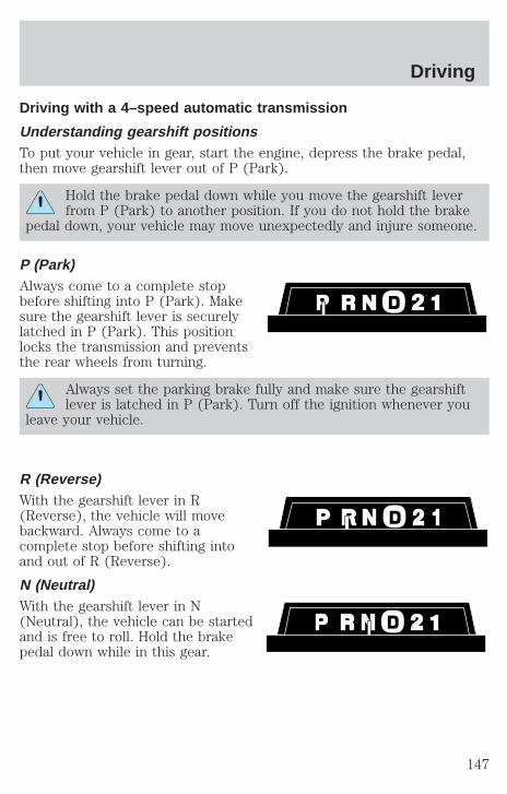
Driving with a 4–speed automatic transmission
Understanding gearshift positionsTo put your vehicle in gear, start the engine, depress the brake pedal,then move gearshift lever out of P (Park).
Hold the brake pedal down while you move the gearshift leverfrom P (Park) to another position. If you do not hold the brake
pedal down, your vehicle may move unexpectedly and injure someone.
P (Park)Always come to a complete stopbefore shifting into P (Park). Makesure the gearshift lever is securelylatched in P (Park). This positionlocks the transmission and preventsthe rear wheels from turning.
Always set the parking brake fully and make sure the gearshiftlever is latched in P (Park). Turn off the ignition whenever you
leave your vehicle.
R (Reverse)With the gearshift lever in R(Reverse), the vehicle will movebackward. Always come to acomplete stop before shifting intoand out of R (Reverse).
N (Neutral)With the gearshift lever in N(Neutral), the vehicle can be startedand is free to roll. Hold the brakepedal down while in this gear.
Driving
147
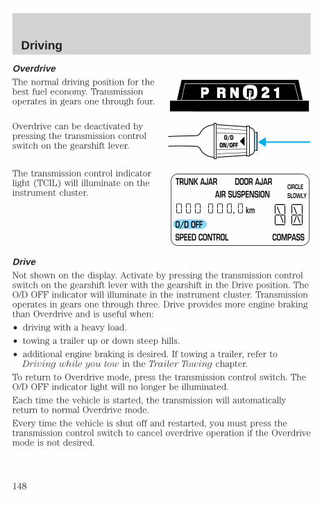
OverdriveThe normal driving position for thebest fuel economy. Transmissionoperates in gears one through four.
Overdrive can be deactivated bypressing the transmission controlswitch on the gearshift lever.
The transmission control indicatorlight (TCIL) will illuminate on theinstrument cluster.
DriveNot shown on the display. Activate by pressing the transmission controlswitch on the gearshift lever with the gearshift in the Drive position. TheO/D OFF indicator will illuminate in the instrument cluster. Transmissionoperates in gears one through three. Drive provides more engine brakingthan Overdrive and is useful when:
• driving with a heavy load.
• towing a trailer up or down steep hills.
• additional engine braking is desired. If towing a trailer, refer toDriving while you tow in the Trailer Towing chapter.
To return to Overdrive mode, press the transmission control switch. TheO/D OFF indicator light will no longer be illuminated.
Each time the vehicle is started, the transmission will automaticallyreturn to normal Overdrive mode.
Every time the vehicle is shut off and restarted, you must press thetransmission control switch to cancel overdrive operation if the Overdrivemode is not desired.
O/DON/OFF
TRUNK AJAR DOOR AJAR AIR SUSPENSION
O/D OFF SPEED CONTROL COMPASS
km
CIRCLE SLOWLY
Driving
148
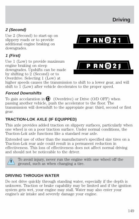
2 (Second)Use 2 (Second) to start-up onslippery roads or to provideadditional engine braking ondowngrades.
1 (First)Use 1 (Low) to provide maximumengine braking on steepdowngrades. Upshifts can be madeby shifting to 2 (Second) or toOverdrive. Selecting 1 (Low) athigher speeds causes the transmission to shift to a lower gear, and willshift to 1 (Low) after vehicle decelerates to the proper speed.
Forced DownshiftsTo gain accelaration in (Overdrive) or Drive (O/D OFF) whenpassing another vehicle, push the accelerator to the floor. Thetransmission will downshift to the appropiate gear: third, second or firstgear.
TRACTION-LOK AXLE (IF EQUIPPED)This axle provides added traction on slippery surfaces, particularly whenone wheel is on a poor traction surface. Under normal conditions, theTraction-Lok axle functions like a standard rear axle.
Extended use of other than the manufacturer’s specified size tires on aTraction-Lok rear axle could result in a permanent reduction ineffectiveness. This loss of effectiveness does not affect normal drivingand should not be noticeable to the driver.
To avoid injury, never run the engine with one wheel off theground, such as when changing a tire.
DRIVING THROUGH WATERDo not drive quickly through standing water, especially if the depth isunknown. Traction or brake capability may be limited and if the ignitionsystem gets wet, your engine may stall. Water may also enter yourengine’s air intake and severely damage your engine.
Driving
149
If driving through deep or standing water is unavoidable, proceed veryslowly. Never drive through water that is higher than the bottom of thehubs (for trucks) or the bottom of the wheel rims (for cars).
Once through the water, always try the brakes. Wet brakes do not stopthe vehicle as effectively as dry brakes. Drying can be improved bymoving your vehicle slowly while applying light pressure on the brakepedal.
Driving through deep water where the transmission vent tube issubmerged may allow water into the transmission and causeinternal transmission damage.
VEHICLE LOADINGBefore loading a vehicle, familiarize yourself with the following terms:
• Base Curb Weight: Weight of the vehicle including any standardequipment, fluids, lubricants, etc. It does not include occupants oraftermarket equipment.
• Payload: Combined maximum allowable weight of cargo, occupantsand optional equipment. The payload equals the gross vehicle weightrating minus base curb weight.
• GVW (Gross Vehicle Weight): Base curb weight plus payloadweight. The GVW is not a limit or a specification.
• GVWR (Gross Vehicle Weight Rating): Maximum permissable totalweight of the base vehicle, occupants, optional equipment and cargo.The GVWR is specific to each vehicle and is listed on the SafetyCertification Label on the driver’s door pillar.
• GAWR (Gross Axle Weight Rating): Carrying capacity for each axlesystem. The GAWR is specific to each vehicle and is listed on theSafety Certification Label on the driver’s door pillar.
• GCW (Gross Combined Weight): The combined weight of thetowing vehicle (including occupants and cargo) and the loaded trailer.
• GCWR (Gross Combined Weight Rating): Maximum permissablecombined weight of the towing vehicle (including occupants andcargo) and the loaded trailer.
• Maximum Trailer Weight Rating: Maximum weight of a trailer thevehicle is permitted to tow. The maximum trailer weight rating isdetermined by subtracting the vehicle curb weight for each
Driving
150
engine/transmission combination, any required option weight for trailertowing and the weight of the driver from the GCWR for the towingvehicle.
• Maximum Trailer Weight: Maximum weight of a trailer the loadedvehicle (including occupants and cargo) is permitted to tow. It isdetermined by subtracting the weight of the loaded trailer towingvehicle from the GCWR for the towing vehicle.
• Trailer Weight Range: Specified weight range that the trailer mustfall within that ranges from zero to the maximum trailer weight rating.
Remember to figure in the tongue load of your loaded trailer whenfiguring the total weight.
Do not exceed the GVWR or the GAWR specified on thecertification label.
Do not use replacement tires with lower load carrying capacities than theoriginals because they may lower the vehicle’s GVWR and GAWRlimitations. Replacement tires with a higher limit than the originals donot increase the GVWR and GAWR limitations.
The Certification Label, found on the inside pillar of the driver’s door,lists several important vehicle weight rating limitations. Before addingany additional equipment, refer to these limitations. If you are addingweight to your vehicle, always ensure that the weight of occupants, cargoand equipment being carried is within the weight limitations that havebeen established for your vehicle including both gross vehicle weight andfront and rear gross axle weight rating limits. Under no circumstanceshould these limitations be exceeded.
Exceeding any vehicle weight rating limitation could result inserious damage to the vehicle and/or personal injury.
The weight of your loaded trailer should not exceed 907 kg (2 000 lbs).The GCW of your vehicle and trailer should not exceed 2 993 kg (6 600lbs).
TRAILER TOWINGYour vehicle is classified as a light duty towing vehicle. Do not tow atrailer until your vehicle has been driven at least 3 200 km (2 000 miles).
Driving
151

Towing a trailer places an additional load on your vehicle’s engine,transmission, brakes, tires and suspension. Inspect these componentscarefully after towing.
Your loaded trailer should weigh no more than 907 kg (2 000 lbs.).
Do not exceed the GVWR or the GAWR specified on thecertification label.
Towing trailers beyond the maximum recommended gross trailerweight could result in engine damage, transmission/axle damage,
structural damage, loss of control, and personal injury.
Preparing to towUse the proper equipment for towing a trailer, and make sure it isproperly attached to your vehicle. See your dealer or a reliable trailerdealer if you require assistance.
HitchesDo not use hitches that clamp onto the vehicle bumper. Use a loadcarrying hitch. You must distribute the load in your trailer so that 10% ofthe total weight of the trailer is on the tongue.
Safety chainsAlways connect the trailer’s safety chains to the frame or hook retainersof the vehicle hitch. To connect the trailer’s safety chains, cross thechains under the trailer tongue and allow slack for turning corners.
If you use a rental trailer, follow the instructions that the rental agencygives to you.
Do not attach safety chains to the bumper.
Trailer brakesElectric brakes and manual, automatic or surge-type trailer brakes aresafe if installed properly and adjusted to the manufacturer’sspecifications. The trailer brakes must meet local and Federalregulations.
Driving
152

Do not connect a trailer’s hydraulic brake system directly to yourvehicle’s brake system. Your vehicle may not have enough
braking power and your chances of having a collision greatly increase.
The braking system of the tow vehicle is rated for operation at theGVWR not GCWR.
Trailer lampsTrailer lamps are required on most towed vehicles. Make sure yourtrailer lamps conform to local and Federal regulations. See your dealer ortrailer rental agency for proper instructions and equipment for hookingup trailer lamps.
Driving while you towWhen towing a trailer:
• Ensure that you turn off your speed control. The speed control mayshut off automatically when you are towing on long, steep grades.
• Consult your local motor vehicle speed regulations for towing a trailer.
• Use a lower gear when towing up or down steep hills. This willeliminate excessive downshifting and upshifting for optimum fueleconomy and transmission cooling.
• Anticipate stops and brake gradually.
Exceeding the GCWR rating may cause internal transmissiondamage and void your warranty coverage.
Servicing after towingIf you tow a trailer for long distances, your vehicle will require morefrequent service intervals. Refer to your scheduled maintenance guide formore information.
Trailer towing tips• Practice turning, stopping and backing up before starting on a trip to
get the feel of the vehicle trailer combination. When turning, makewider turns so the trailer wheels will clear curbs and other obstacles.
• Allow more distance for stopping with a trailer attached.
Driving
153

• If you are driving down a long or steep hill, shift to a lower gear. Donot apply the brakes continuously, as they may overheat and becomeless effective.
• The trailer tongue weight should be 10% of the loaded trailer weight.
• After you have traveled 80 km (50 miles), thoroughly check yourhitch, electrical connections and trailer wheel lug nuts.
• When stopped in traffic for long periods of time in hot weather, placethe gearshift in P (Park) and increase idle speed. This aids enginecooling and air conditioner efficiency.
• Vehicles with trailers should not be parked on a grade. If you mustpark on a grade, place wheel chocks under the trailer’s wheels.
Launching or retrieving a boatWhen backing down a ramp during boat launching or retrieval:
• do not allow the static water level to rise above the bottom edge ofthe rear bumper.
• do not allow waves to break higher than 15 cm (6 inches) above thebottom edge of the rear bumper.
Exceeding these limits may allow water to enter critical vehiclecomponents, adversely affecting driveability, emissions, reliability andcausing internal transmission damage.
Replace the rear axle lubricant any time the axle has been submerged inwater. Rear axle lubricant quantities are not to be checked or changedunless a leak is suspected or repair required.
Disconnect the wiring to the trailer before backing the trailer into thewater. Reconnect the wiring to the trailer after the trailer is removedfrom the water.
RECREATIONAL TOWING (ALL WHEELS ON THE GROUND)Follow these guidelines for your specific powertrain combination to towyour vehicle with all four wheels on the ground (such as behind arecreational vehicle).
These guidelines are designed to ensure that your transmission is notdamaged due to insufficient lubrication.
All Rear Wheel Drive (RWD) vehicles
This applies to all cars and 4x2 trucks/sport utilities with rear wheeldrive capability.
Driving
154

An example of recreational towing is towing your vehicle behind amotorhome. The following recreational towing guidelines are designed toensure that your transmission is not damaged.
• Place the transmission in N (Neutral).
• Maximum speed is 56 km/h (35 mph).
• Maximum distance is 80 km (50 miles).
If a distance of 80 km (50 miles) or a speed of 56 km/h (35 mph) mustbe exceeded, you must disconnect the driveshaft. Ford recommends thedriveshaft be removed/installed only by a qualified technician. See yourlocal dealer for driveshaft removal/installation.
Improper removal/installation of the driveshaft can causetransmission fluid loss, damage to the driveshaft and internaltransmission components.
Driving
155
GETTING ROADSIDE ASSISTANCETo fully assist if you should have a vehicle concern, Ford Motor Companyoffers a complimentary roadside assistance program. This program isseparate from the New Vehicle Limited Warranty. The service is available:
• 24–hours, seven days a week
• for the Basic warranty period (Canada) or New Vehicle LimitedWarranty period (U.S.) of three years or 60 000 km (36 000 miles),whichever comes first on Ford and Mercury vehicles, and four years or80 000 km (50 000 miles) on Lincoln vehicles
Roadside assistance will cover:
• changing a flat tire
• jump-starts
• lock-out assistance
• limited fuel delivery*
• towing of your disabled vehicle to the nearest Ford Motor Companydealership, or your selling dealer if within 25 kms (15.5 miles) of thenearest Ford Motor Company dealership (one tow per disablement).Even non-warranty related tows, like accidents or getting stuck in themud or snow, are covered (some exclusions apply, such as impoundtowing or repossession).
* Canadian customers refer to your Roadside Assistance supplementfor exact fuel amounts.
USING ROADSIDE ASSISTANCEComplete the roadside assistance identification card and place it in yourwallet for quick reference. In the United States, this card is found in theOwner Guide portfolio in the glove compartment in Ford vehicles and ismailed to you if you own a Mercury or Lincoln. In Canada, the card isfound in the Roadside Assistance book in the glove compartment.
U.S. Ford or Mercury vehicle customers who require roadside assistance,call 1–800–241–3673; Lincoln vehicle customers call 1–800–521–4140.
Canadian customers who require roadside assistance, call1–800–665–2006.
Roadside Emergencies
156
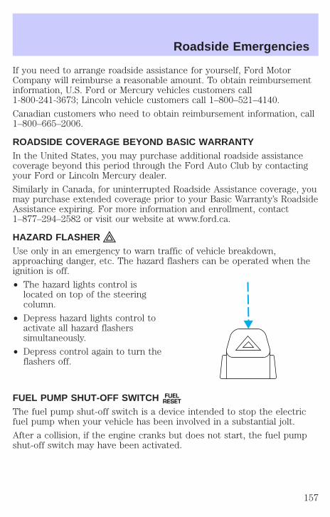
If you need to arrange roadside assistance for yourself, Ford MotorCompany will reimburse a reasonable amount. To obtain reimbursementinformation, U.S. Ford or Mercury vehicles customers call1-800-241-3673; Lincoln vehicle customers call 1–800–521–4140.
Canadian customers who need to obtain reimbursement information, call1–800–665–2006.
ROADSIDE COVERAGE BEYOND BASIC WARRANTYIn the United States, you may purchase additional roadside assistancecoverage beyond this period through the Ford Auto Club by contactingyour Ford or Lincoln Mercury dealer.
Similarly in Canada, for uninterrupted Roadside Assistance coverage, youmay purchase extended coverage prior to your Basic Warranty’s RoadsideAssistance expiring. For more information and enrollment, contact1–877–294–2582 or visit our website at www.ford.ca.
HAZARD FLASHERUse only in an emergency to warn traffic of vehicle breakdown,approaching danger, etc. The hazard flashers can be operated when theignition is off.
• The hazard lights control islocated on top of the steeringcolumn.
• Depress hazard lights control toactivate all hazard flasherssimultaneously.
• Depress control again to turn theflashers off.
FUEL PUMP SHUT-OFF SWITCH FUELRESET
The fuel pump shut-off switch is a device intended to stop the electricfuel pump when your vehicle has been involved in a substantial jolt.
After a collision, if the engine cranks but does not start, the fuel pumpshut-off switch may have been activated.
Roadside Emergencies
157

The fuel pump shut-off switch islocated on a bracket inside of theluggage compartment.
Use the following procedure to reset the fuel pump shut-off switch.
1. Turn the ignition to the OFF position.
2. Check the fuel system for leaks.
3. If no fuel leak is apparent, reset the fuel pump shut-off switch bypushing in on the reset button.
4. Turn the ignition to the ON position. Pause for a few seconds andreturn the key to the OFF position.
5. Make a further check for leaks in the fuel system.
FUSES AND RELAYS
FusesIf electrical components in thevehicle are not working, a fuse mayhave blown. Blown fuses areidentified by a broken wire withinthe fuse. Check the appropriatefuses before replacing any electricalcomponents.
Note: Always replace a fuse with one that has the specified amperagerating. Using a fuse with a higher amperage rating can cause severe wiredamage and could start a fire.
15
Roadside Emergencies
158

Standard fuse amperage rating and color
COLOR
Fuse
rating
Mini
fuses
Standard
fuses
Maxi
fuses
Cartridge
maxi
fuses
Fuse link
cartridge
2A Grey Grey — — —3A Violet Violet — — —4A Pink Pink — — —5A Tan Tan — — —
7.5A Brown Brown — — —10A Red Red — — —15A Blue Blue — — —20A Yellow Yellow Yellow Blue Blue25A Natural Natural — — —30A Green Green Green Pink Pink40A — — Orange Green Green50A — — Red Red Red60A — — Blue — Yellow70A — — Tan — Brown80A — — Natural — Black
Passenger compartment fuse panelThe fuse panel is located below and to the left of the steering wheel bythe brake pedal. Remove the panel cover to access the fuses.
To remove a fuse use the fuse puller tool provided on the fuse panelcover.
Roadside Emergencies
159
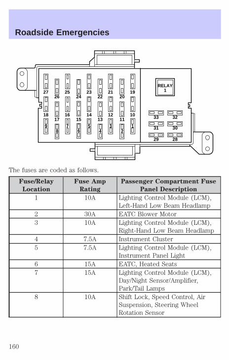
The fuses are coded as follows.
Fuse/Relay
Location
Fuse Amp
Rating
Passenger Compartment Fuse
Panel Description
1 10A Lighting Control Module (LCM),Left-Hand Low Beam Headlamp
2 30A EATC Blower Motor3 10A Lighting Control Module (LCM),
Right-Hand Low Beam Headlamp4 7.5A Instrument Cluster5 7.5A Lighting Control Module (LCM),
Instrument Panel Light6 15A EATC, Heated Seats7 15A Lighting Control Module (LCM),
Day/Night Sensor/Amplifier,Park/Tail Lamps
8 10A Shift Lock, Speed Control, AirSuspension, Steering WheelRotation Sensor
27 2526 24
23 2122
1920
18 1617 15
14 1213
10 33
31
29
32
30
28
119 7
8 65 3
41
2
RELAY1
Roadside Emergencies
160

Fuse/Relay
Location
Fuse Amp
Rating
Passenger Compartment Fuse
Panel Description
9 20A Lighting Control Module (LCM),Multi-Function Switch, Hi BeamHeadlamps
10 10A Restraint Control Module (RCM),Air Bags
11 — Not Used12 15A Instrument Cluster, Anti-Theft,
Ignition Switch, Ignition Coils13 10A Anti-Lock Brake Module, Traction
Control Switch14 7.5A Transmission Control Switch,
Lighting Control Module (LCM),VCS
15 20A Multi-Function Switch, TurnSignals
16 30A Wiper Control Module (WCM),Windshield Wiper Motor
17 10A Digital Transmission Range (DTR)Sensor, Back-Up Lamps, ECMirrors
18 7.5A Lighting Control Module (LCM),Front Radio Control Unit, CellularTelephone Transceiver, ElectronicDay/Night Mirror, CompassModule/Rear Audio/ClimateControl Module, VCS
19 10A EATC, Clock, Instrument Cluster,PCM
20 7.5A Lighting Control Module (LCM),ABS, Shift Lock
21 20A Multi-Function Switch, HazardLamps
Roadside Emergencies
161
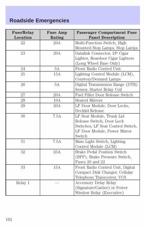
Fuse/Relay
Location
Fuse Amp
Rating
Passenger Compartment Fuse
Panel Description
22 20A Multi-Function Switch, HighMounted Stop Lamps, Stop Lamps
23 20A Datalink Connector, I/P CigarLighter, Reardoor Cigar Lighters(Long Wheel Base Only)
24 5A Front Radio Control Unit25 15A Lighting Control Module (LCM),
Courtesy/Demand Lamps26 5A Digital Transmission Range (DTR)
Sensor, Starter Relay Coil27 20A Fuel Filler Door Release Switch28 10A Heated Mirrors29 20A LF Door Module, Door Locks,
Decklid Release30 7.5A LF Seat Module, Trunk Lid
Release Switch, Door LockSwitches, LF Seat Control Switch,LF Door Module, Power MirrorSwitch
31 7.5A Main Light Switch, LightingControl Module (LCM)
32 25A Brake Pedal Position Switch(BPP), Brake Pressure Switch,Fuses 20 and 22
33 15A Front Radio Control Unit, DigitalCompact Disk Changer, CellularTelephone Transceiver, VCS
Relay 1 — Accessory Delay Relay(Signature/Cartier) or PowerWindow Relay (Executive)
Roadside Emergencies
162
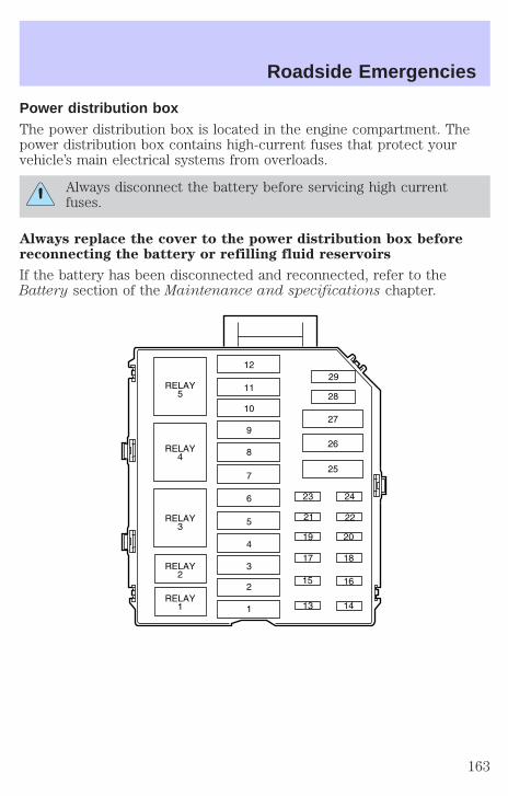
Power distribution boxThe power distribution box is located in the engine compartment. Thepower distribution box contains high-current fuses that protect yourvehicle’s main electrical systems from overloads.
Always disconnect the battery before servicing high currentfuses.
Always replace the cover to the power distribution box beforereconnecting the battery or refilling fluid reservoirs
If the battery has been disconnected and reconnected, refer to theBattery section of the Maintenance and specifications chapter.
Roadside Emergencies
163
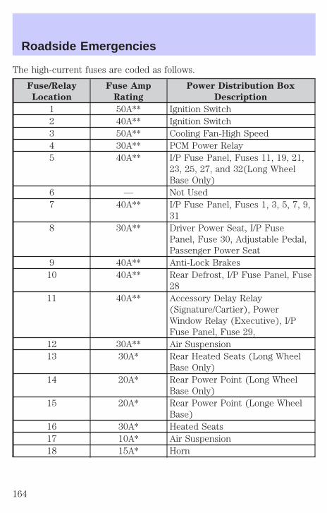
The high-current fuses are coded as follows.
Fuse/Relay
Location
Fuse Amp
Rating
Power Distribution Box
Description
1 50A** Ignition Switch2 40A** Ignition Switch3 50A** Cooling Fan-High Speed4 30A** PCM Power Relay5 40A** I/P Fuse Panel, Fuses 11, 19, 21,
23, 25, 27, and 32(Long WheelBase Only)
6 — Not Used7 40A** I/P Fuse Panel, Fuses 1, 3, 5, 7, 9,
318 30A** Driver Power Seat, I/P Fuse
Panel, Fuse 30, Adjustable Pedal,Passenger Power Seat
9 40A** Anti-Lock Brakes10 40A** Rear Defrost, I/P Fuse Panel, Fuse
2811 40A** Accessory Delay Relay
(Signature/Cartier), PowerWindow Relay (Executive), I/PFuse Panel, Fuse 29,
12 30A** Air Suspension13 30A* Rear Heated Seats (Long Wheel
Base Only)14 20A* Rear Power Point (Long Wheel
Base Only)15 20A* Rear Power Point (Longe Wheel
Base)16 30A* Heated Seats17 10A* Air Suspension18 15A* Horn
Roadside Emergencies
164
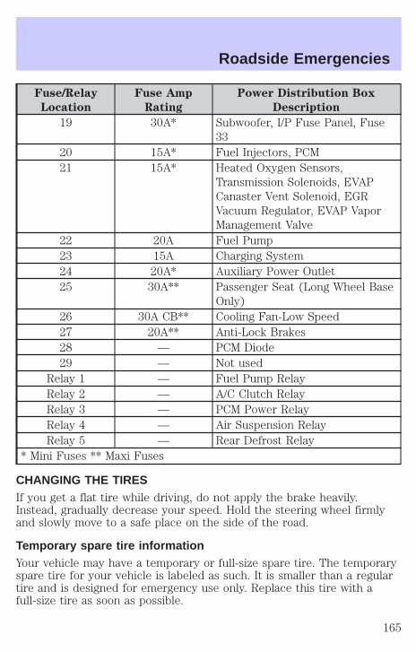
Fuse/Relay
Location
Fuse Amp
Rating
Power Distribution Box
Description
19 30A* Subwoofer, I/P Fuse Panel, Fuse33
20 15A* Fuel Injectors, PCM21 15A* Heated Oxygen Sensors,
Transmission Solenoids, EVAPCanaster Vent Solenoid, EGRVacuum Regulator, EVAP VaporManagement Valve
22 20A Fuel Pump23 15A Charging System24 20A* Auxiliary Power Outlet25 30A** Passenger Seat (Long Wheel Base
Only)26 30A CB** Cooling Fan-Low Speed27 20A** Anti-Lock Brakes28 — PCM Diode29 — Not used
Relay 1 — Fuel Pump RelayRelay 2 — A/C Clutch RelayRelay 3 — PCM Power RelayRelay 4 — Air Suspension RelayRelay 5 — Rear Defrost Relay
* Mini Fuses ** Maxi Fuses
CHANGING THE TIRESIf you get a flat tire while driving, do not apply the brake heavily.Instead, gradually decrease your speed. Hold the steering wheel firmlyand slowly move to a safe place on the side of the road.
Temporary spare tire informationYour vehicle may have a temporary or full-size spare tire. The temporaryspare tire for your vehicle is labeled as such. It is smaller than a regulartire and is designed for emergency use only. Replace this tire with afull-size tire as soon as possible.
Roadside Emergencies
165

If you use the temporary spare tire continuously or do not followthese precautions, the tire could fail, causing you to lose control
of the vehicle, possibly injuring yourself or others.
When driving with the temporary spare tire do not:
• exceed 80 km/h (50 mph) under any circumstances
• load the vehicle beyond maximum vehicle load rating listed on theSafety Compliance Label
• tow a trailer
• use tire chains
• drive through an automatic car wash, because of the vehicle’s reducedground clearance
• try to repair the temporary spare tire or remove it from its wheel
• use the wheel for any other type of vehicle
Tire change procedure
To prevent the vehicle from moving when you change a tire, besure the parking brake is set, then block (in both directions) the
wheel that is diagonally opposite (other side and end of the vehicle) tothe tire being changed.
If the vehicle slips off the jack, you or someone else could beseriously injured.
1. Park on a level surface, activatehazard flashers and set parkingbrake.
HOOD
Roadside Emergencies
166
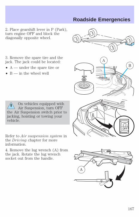
2. Place gearshift lever in P (Park),turn engine OFF and block thediagonally opposite wheel.
3. Remove the spare tire and thejack. The jack could be located:
• A — under the spare tire or
• B — in the wheel well
On vehicles equipped withAir Suspension, turn OFF
the Air Suspension switch prior tojacking, hoisting or towing yourvehicle.
Refer to Air suspension system inthe Driving chapter for moreinformation.
4. Remove the lug wrench (A) fromthe jack. Rotate the lug wrenchsocket out from the handle.
BA
OFF
A
Roadside Emergencies
167

5. Locate pry off notch (ifequipped) and remove the centerornament from the aluminum wheelwith the tapered end of the wheelnut wrench that came with yourvehicle. Insert and twist the handle,then pry against the wheel.
6. Loosen each wheel lug nutone-half turn counterclockwise butdo not remove them until the wheel is raised off the ground.
Before placing the jack under the vehicle, NOTE the jack locationmarkings:
JACK LOCATION
The jack location markings can befound on the lower outer edge ofthe body.
• Locate the jack locator mark (B)on the body (C) near the tire youare changing, then place the jack(D) under the frame (A) ofthe vehicle aligning it with themark (B).
• Position the jack according to thefollowing guides and turn the jackhandle clockwise until the wheelis completely off the ground.
B
C
D
A
Roadside Emergencies
168

To lessen risk of personnalinjury, do not put any part
of your body under the vehiclewhile changing a tire. Do not startthe engine when your vehicle ison the jack. The jack is ONLYmeant for changing the tire.
• Never use the rear differentialas a jacking point.
7. Remove the lug nuts with the lug wrench.
8. Replace the flat tire with the spare tire, making sure the valve stem isfacing outward. Reinstall lug nuts until the wheel is snug against the hub.Do not fully tighten the lug nuts until the wheel has been lowered.
9. Lower the vehicle by turning the jack handle counterclockwise.
10. Remove the jack and fullytighten the lug nuts in the ordershown.
11. Put flat tire, jack and lug wrenchaway.
12. Turn on the air suspensionswitch.
JUMP STARTING YOUR VEHICLE
The gases around the battery can explode if exposed to flames,sparks, or lit cigarettes. An explosion could result in injury or
vehicle damage.
Batteries contain sulfuric acid which can burn skin, eyes, andclothing, if contacted.
1
43
25
Roadside Emergencies
169

Do not attempt to push-start your vehicle. Automatictransmissions do not have push-start capability; also, thecatalytic conveter may become damaged.
Preparing your vehicleWhen the battery is disconnected or a new battery is installed, thetransmission must relearn its adaptive strategy. As a result of this, thetransmission may shift firmly. This operation is considered normal andwill not affect function or durability of the transmission. Over time, theadaptive learning process will fully update transmission operation to itsoptimum shift feel.
1. Use only a 12–volt supply to start your vehicle.
2. Do not disconnect the battery of the disabled vehicle as this coulddamage the vehicle’s electrical system.
3. Park the booster vehicle close to the hood of the disabled vehiclemaking sure the two vehicles do not touch. Set the parking brake onboth vehicles and stay clear of the engine cooling fan and other movingparts.
4. Check all battery terminals and remove any excessive corrosion beforeyou attach the battery cables. Ensure that vent caps are tight and level.
5. Turn the heater fan on in both vehicles to protect any electricalsurges. Turn all other accessories off.
Connecting the jumper cables
1. Connect the positive (+) booster cable to the positive (+) terminal ofthe discharged battery.
+–
+–
Roadside Emergencies
170

Note: In the illustrations, lightning bolts are used to designate theassisting (boosting) battery.
2. Connect the other end of the positive (+) cable to the positive (+)terminal of the assisting battery.
3. Connect the negative (-) cable to the negative (-) terminal of theassisting battery.
+–
+–
+–
+–
Roadside Emergencies
171

4. Make the final connection of the negative (-) cable to an exposedmetal part of the stalled vehicle’s engine, away from the battery and thecarburetor/fuel injection system. Do not use fuel lines, engine rockercovers or the intake manifold as grounding points.
Do not connect the end of the second cable to the negative (-)terminal of the battery to be jumped. A spark may cause an
explosion of the gases that surround the battery.
5. Ensure that the cables are clear of fan blades, belts, moving parts ofboth engines, or any fuel delivery system parts.
Jump starting1. Start the engine of the booster vehicle and run the engine atmoderately increased speed.
2. Start the engine of the disabled vehicle.
3. Once the disabled vehicle has been started, run both engines for anadditional three minutes before disconnecting the jumper cables.
+–
+–
Roadside Emergencies
172

Removing the jumper cables
Remove the jumper cables in the reverse order that they wereconnected.
1. Remove the jumper cable from the ground metal surface.
Note: In the illustrations, lightning bolts are used to designate theassisting (boosting) battery.
2. Remove the jumper cable on the negative (-) connection of thebooster vehicle’s battery.
+–
+–
+–
+–
Roadside Emergencies
173
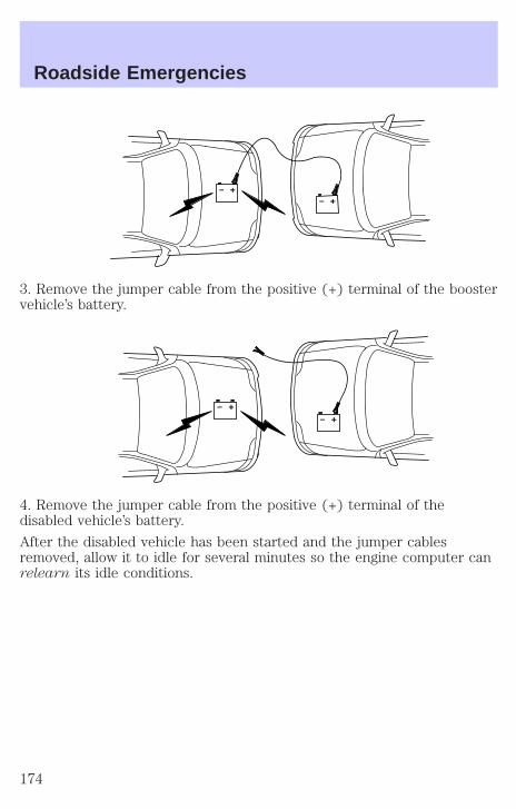
3. Remove the jumper cable from the positive (+) terminal of the boostervehicle’s battery.
4. Remove the jumper cable from the positive (+) terminal of thedisabled vehicle’s battery.
After the disabled vehicle has been started and the jumper cablesremoved, allow it to idle for several minutes so the engine computer canrelearn its idle conditions.
+–
+–
+–
+–
Roadside Emergencies
174

WRECKER TOWING
If you need to have your vehicle towed, contact a professional towingservice or, if you are a member, your roadside assistance center.
It is recommended that your vehicle be towed with a wheel lift or flatbedequipment. Do not tow with a slingbelt. Ford Motor Company has notapproved a slingbelt towing procedure.
Before your vehicle can be towed, the air suspension control in theluggage compartment must be turned to the OFF position (if equipped).
If the vehicle is towed by other means or incorrectly, vehicledamage may occur.
Ford Motor Company provides a towing manual for all authorized towtruck operators. Have your tow truck operator refer to this manual forproper hook-up and towing procedures for your vehicle.
Roadside Emergencies
175
GETTING THE SERVICES YOU NEED
At homeFord Motor Company and Ford of Canada have authorized dealerships toservice your vehicle. It is preferred that you return to the Ford dealerwhere your vehicle was purchased when warranty repairs are needed.However, you may also take your vehicle to another Ford MotorCompany or Ford of Canada dealership authorized for warranty repairs.Certain warranty repairs require special training though, so not alldealers are authorized to perform all warranty repairs. That means thatdepending on the warranty repair needed, the vehicle may need to betaken to another dealer. If a particular dealership can not assist you,then contact the Customer Relationship Center.
If you have questions or concerns, or are unsatisfied with the service youare receiving, follow these steps:
1. Contact your Sales Representative or Service Advisor at yourselling/servicing dealership.
2. If your inquiry or concern remains unresolved, contact the SalesManager or Service Manager at the dealership.
3. If the inquiry or concern cannot be resolved at the dealership level,please contact the Ford Customer Relationship Center.
Away from homeIf you own a Ford or Mercury vehicle and are away from home whenyour vehicle needs service, or if you need more help than the dealershipcould provide, after following the steps described above, contact theFord Customer Relationship Center to find an authorized dealership tohelp you. In the United States:
Ford Motor CompanyCustomer Relationship Center16800 Executive Plaza DriveP.O. Box 6248Dearborn, Michigan 481211-800-392-3673 (FORD)(TDD for the hearing impaired: 1-800-232-5952)
Customer Assistance
176

In Canada:Customer Relationship CentreFord Motor Company of Canada, LimitedP.O. Box 2000Oakville, Ontario L6J 5E41-800-565-3673 (FORD)
If you own a Lincoln vehicle and are away from home when your vehicleneeds service, or if you need more help than the dealership couldprovide, after following the steps described above, contact the FordCustomer Relationship Center to find an authorized dealership to helpyou.
In the United States:Ford Motor CompanyCustomer Relationship Center16800 Executive Plaza DriveP.O. Box 6248Dearborn, Michigan 481211-800-521-4140(TDD for the hearing impaired: 1-800-232-5952)
In Canada:Customer Relationship CentreFord Motor Company of Canada, LimitedP.O. Box 2000Oakville, Ontario L6J 5E41-800-565-3673 (FORD)
In order to help you service your Ford or Lincoln Mercury vehicle, pleasehave the following information available when contacting a CustomerRelationship Center:
• Your telephone number (home and business).
• The name of the dealer and the city where the dealership is located.
• The year and make of your vehicle.
• The date of vehicle purchase.
• The current odometer reading.
• The vehicle identification number (VIN).
If you still have a complaint involving a warranty dispute, you may wishto contact the Dispute Settlement Board (U.S.).
Customer Assistance
177
In some states (in the U.S.) you must directly notify Ford in writingbefore pursuing remedies under your state’s warranty laws. Ford is alsoallowed a final repair attempt in some states.
In the United States, a warranty dispute must be submitted to theDispute Settlement Board before taking action under the Magnuson-MossWarranty Act, or to the extent allowed by state law, before pursuingreplacement or repurchase remedies provided by certain state laws. Thisdispute handling procedure is not required prior to enforcing statecreated rights or other rights which are independent of theMagnuson-Moss Warranty Act or state replacement or repurchase laws.
FORD EXTENDED SERVICE PLANYou can get more protection for your new car or light truck bypurchasing Ford Extended Service Plan (Ford ESP) coverage. Ford ESPis an optional service contract which is backed by Ford Motor Companyor Ford Motor Service Company (in the U.S.) and Ford of Canada (inCanada). It provides the following:
• Benefits during the warranty period depending on the plan youpurchase (such as: reimbursement for rentals; coverage for certainmaintenance and wear items).
• Protection against covered repair costs after your Bumper-to-BumperWarranty expires.
You may purchase Ford ESP from any participating Ford and LincolnMercury and Ford of Canada dealer. There are several plans available invarious time, distance and deductible combinations which can be tailoredto fit your own driving needs. Ford ESP also offers reimbursementbenefits for towing and rental coverage.
When you buy Ford ESP, you receive Peace-of-Mind protectionthroughout the United States and Canada, provided by a network ofmore than 5,000 participating Ford or Lincoln Mercury and Ford ofCanada dealers.
If you did not take advantage of the Ford Extended Service Plan at thetime of purchasing your vehicle, you may still be eligible. Please contactyour dealer for further information. Since this information is subject tochange, please ask your dealer for complete details about Ford ExtendedService Plan coverage options, or visit the Ford ESP website atwww.ford-esp.com.
Customer Assistance
178

THE DISPUTE SETTLEMENT BOARD (U.S. ONLY)The Dispute Settlement Board is:
• an independent, third-party arbitration program for warranty disputes
• available free to owners and lessees of qualifying Ford Motor Companyvehicles
The Dispute Settlement Board may not be available in all states. FordMotor Company reserves the right to change eligibility limitations, modifyprocedures and/or to discontinue this service without notice and withoutincurring obligations per applicable state law.
What kinds of cases does the Board review?Unresolved warranty repair concerns or vehicle performance concerns ason Ford and Lincoln Mercury cars and Ford and Lincoln Mercury lighttrucks which are within the terms of any applicable written new vehiclewarranty are eligible for review, except those involving:
• a non-Ford product
• a non-Ford dealership
• sales disputes between customer and dealer except those associatedwith warranty repairs or concerns with the vehicle’s performance asdesigned
• a request for reimbursement of consequential expenses unless aservice or product concern is being reviewed
• items not covered by the New Vehicle Limited Warranty (includingmaintenance and wear items)
• alleged personal injury/property damage claims
• cases currently in litigation
• vehicles not used primarily for family, personal or household purposes(except in states where the Dispute Settlement Board is required toreview commercial vehicles)
• vehicles with non-U.S. warranties
Concerns are ineligible for review if the New Vehicle Limited Warrantyhas expired at receipt of your application and, in certain states eligibilityis dependent upon the customer’s possession of the vehicle.
Eligibility may differ according to state law. For example, see the uniquebrochures for California, West Virginia, Georgia and Wisconsinpurchasers/lessees.
Customer Assistance
179
Board membershipThe Board consists of:
• three consumer representatives
• a Ford or Lincoln Mercury dealership representative
Consumer candidates for Board membership are recruited and trained byan independent consulting firm. The dealership Board member is chosenfrom Ford and Lincoln Mercury dealership management, recognized fortheir business leadership qualities.
What the Board needsTo have your case reviewed you must complete the application in theDSB brochure and mail it to the address provided on the applicationform. Some states will require you to use certified mail, with returnreceipt requested.
Your application is reviewed and, if it is determined to be eligible, youwill receive an acknowledgment indicating:
• The file number assigned to your application.
• The toll-free phone number of the DSB’s independent administrator.
Your dealership and a Ford Motor Company representative will then beasked to submit statements.
To properly review your case, the Board needs the following information:
• Legible copies of all documents and maintenance or repair ordersrelevant to the case.
• The year, make, model, and Vehicle Identification Number (VIN) listedon your vehicle ownership license.
• The date of repair(s) and mileage at the time of occurrence(s).
• The current mileage.
• The name of the dealer(s) who sold or serviced the vehicle.
• A brief description of your unresolved concern.
• A brief summary of the action taken by the dealer(s) and Ford MotorCompany.
• The names (if known) of all the people you contacted at thedealership(s).
• A description of the action you expect to resolve your concern.
Customer Assistance
180

You will receive a letter of explanation if your application does notqualify for Board review.
Oral presentationsIf you would like to make an oral presentation, indicate YES to question6 on the application. While it is your right to make an oral presentationbefore the Board, this is not a requirement and the Board will decide thecase whether or not an oral presentation is made. An oral presentationmay be requested by the Board as well.
Making a decisionBoard members review all available information related to eachcomplaint, including oral presentations, and arrive at a fair and impartialdecision. Board review may be terminated at any time by either party.
Every effort is made to decide the case within 40 days of the date thatall requested information is received by the Board. Since the Boardgenerally meets once a month, it may take longer for the Board toconsider some cases.
After a case is reviewed, the Board mails you a decision letter and aform on which to accept or reject the Board’s decision. The decisions ofthe Board are binding on Ford (and, in some cases, on the dealer) butnot on consumers who are free to pursue other remedies available tothem under state or federal law.
To Request a DSB Brochure/ApplicationFor a brochure/application, speak to your dealer or write/call to theBoard at the following address/phone number:
Dispute Settlement BoardP.O. Box 5120Southfield, MI 48086–51201–800–428–3718
You may also contact the North American Customer Relationship Centerat 1-800-392-3673 (Ford), TDD for the hearing impaired: 1-800-232-5952or by writing to the Center at the following address:
Ford Motor CompanyCustomer Relationship Center16800 Executive Plaza DriveP.O. Box 6248Dearborn, Michigan 48121
Customer Assistance
181
UTILIZING THE MEDIATION/ARBITRATION PROGRAM(CANADA ONLY)In those cases where you continue to feel that the efforts by Ford andthe dealer to resolve a factory-related vehicle service concern have beenunsatisfactory, Ford of Canada participates in an impartial third partymediation/arbitration program administered by the Canadian MotorVehicle Arbitration Plan (CAMVAP).
The CAMVAP program is a straight-forward and relatively speedyalternative to resolve a disagreement when all other efforts to produce asettlement have failed. This procedure is without cost to you and isdesigned to eliminate the need for lengthy and expensive legalproceedings.
In the CAMVAP program, impartial third-party arbitrators conducthearings at mutually convenient times and places in an informalenvironment. These impartial arbitrators review the positions of theparties, make decisions and, when appropriate, render awards to resolvedisputes. CAMVAP decisions are fast, fair, and final; the arbitrator’saward is binding both to you and Ford of Canada.
CAMVAP services are available in all territories and provinces. For moreinformation, without charge or obligation, call your CAMVAP ProvincialAdministrator directly at 1-800-207-0685.
GETTING ASSISTANCE OUTSIDE THE U.S. AND CANADABefore exporting your vehicle to a foreign country, contact theappropriate foreign embassy or consulate. These officials can inform youof local vehicle registration regulations and where to find unleaded fuel.
If you cannot find unleaded fuel or can only get fuel with an anti-knockindex lower than is recommended for your vehicle, contact a district orowner relations/customer relationship office.
The use of leaded fuel in your vehicle without proper conversion maydamage the effectiveness of your emission control system and may causeengine knocking or serious engine damage. Ford Motor Company/Ford ofCanada is not responsible for any damage caused by use of improperfuel.
In the United States, using leaded fuel may also result in difficultyimporting your vehicle back into the U.S.
Customer Assistance
182
If your vehicle must be serviced while you are traveling or living inCentral or South America, the Caribbean, or the Middle East, contact thenearest Ford dealership. If the dealership cannot help you, write or call:
FORD MOTOR COMPANYWORLDWIDE DIRECT MARKET OPERATIONS1555 Fairlane DriveFairlane Business Park #3Allen Park, Michigan 48101U.S.A.Telephone: (313) 594-4857FAX: (313) 390-0804
If you are in another foreign country, contact the nearest Forddealership. If the dealership employees cannot help you, they can directyou to the nearest Ford affiliate office.
If you buy your vehicle in North America and then relocate outside ofthe U.S. or Canada, register your vehicle identification number (VIN) andnew address with Ford Motor Company Worldwide Direct MarketOperations.
ORDERING ADDITIONAL OWNER’S LITERATURETo order the publications in this portfolio, contact Helm, Incorporated at:
HELM, INCORPORATEDP.O. Box 07150Detroit, Michigan 48207
Or call:
For a free publication catalog, order toll free: 1-800-782-4356
Monday-Friday 8:00 a.m. - 6:00 p.m. EST
(Items in this catalog may be purchased by credit card holders only.)
Obtaining a French owner’s guideFrench Owner’s Guides can be obtained from your dealer or by writing toFord Motor Company of Canada, Limited, Service Publications, P.O. Box1580, Station B, Mississauga, Ontario L4Y 4G3.
Customer Assistance
183

IN CALIFORNIA (U.S. ONLY)California Civil Code Section 1793.2(d) requires that, if a manufactureror its representative is unable to repair a motor vehicle to conform to thevehicle’s applicable express warranty after a reasonable number ofattempts, the manufacturer shall be required to either replace thevehicle with one substantially identical or repurchase the vehicle andreimburse the buyer in an amount equal to the actual price paid orpayable by the consumer (less a reasonable allowance for consumeruse). The consumer has the right to choose whether to receive a refundor replacement vehicle.
California Civil Code Section 1793.22(b) presumes that the manufacturerhas had a reasonable number of attempts to conform the vehicle to itsapplicable express warranties if, within the first 18 months of ownershipof a new vehicle or the first 29 000 km (18 000 miles), whichever occursfirst:
1. Two or more repair attempts are made on the same nonconformitylikely to cause death or serious bodily injury OR
2. Four or more repair attempts are made on the same nonconformity (adefect or condition that substantially impairs the use, value or safety ofthe vehicle) OR
3. The vehicle is out of service for repair of nonconformities for a total ofmore than 30 calendar days (not necessarily all at one time)
In the case of 1 or 2 above, the consumer must also notify themanufacturer of the need for the repair of the nonconformity at thefollowing address:
16800 Executive Plaza DriveMail Drop 3NE-BDearborn, MI 48126
Customer Assistance
184
REPORTING SAFETY DEFECTS (U.S. ONLY)If you believe that your vehicle hasa defect which could cause a crash,or could cause injury or death, youshould immediately inform theNational Highway Traffic SafetyAdministration (NHTSA) in additionto notifying Ford Motor Company.
If NHTSA receives similar complaints, it may open an investigation, andif it finds that a safety defect exists in a group of vehicles, it may order arecall and remedy campaign. However, NHTSA cannot become involvedin individual problems between you, your dealer or Ford Motor Company.
To contact NHTSA, you may either call the Auto Safety Hotline toll-freeat 1–800–424–9393 (202–366–0123 in the Washington D.C. area) or writeto:
NHTSAU.S. Department of Transportation400 Seventh StreetWashington, D.C. 20590
You can also obtain other information about motor vehicle safety fromthe Hotline.
Customer Assistance
185

WASHING THE EXTERIOR OF YOUR VEHICLENever wash a vehicle that is “hot tothe touch” or during exposure tostrong, direct sunlight. It isrecommended that you wash yourvehicle regularly with cool orlukewarm water and a neutral Phshampoo, such as Detail Wash(ZC-3–A), which is available fromyour authorized Ford, Lincoln orMercury dealer. Always use a cleansponge or carwash mitt with plentyof water for best results. Dry the vehicle with a chamois or soft terrycloth towel in order to eliminate water spotting.
Never use strong household detergents or soap, such as dishwashing or laundry liquid. These products can discolor and spotpainted surfaces.
It is especially important to wash the vehicle regularly during wintermonths, as dirt and road salt are difficult to remove and do causedamage to the vehicle.
Items such as gasoline, diesel fuel, bird droppings and insect depositsshould be washed and sponged off as soon as possible. Deposits notremoved promptly can cause damage to the vehicle’s paintwork and trimover time.
Remove any exterior accessories, such as antennas, beforeentering a car wash.
PROTECTING THE PAINT FINISH OF YOUR VEHICLEApplying a polymer paint sealant to your vehicle on a regular basis willassist in reducing minor scratches and paint damage.
A typical paint sealant lasts approximately six months to a year,depending on local weather conditions and the cleaning soap that is usedin washing the vehicle.
Do not use a wax that beads excessively.
Do not allow paint sealant to come in contact with any non-body(low-gloss black) colored trim, such as grained door handles, roofracks, bumpers, side moldings, mirror housings or the windshieldcowl area. The paint sealant will “gray” or stain the parts over time.
Cleaning
186
REPAIRING PAINT CHIPSRemove particles such as bird droppings, tree sap, insect deposits, tarspots, road salt and industrial fallout before repairing paint chips.
Minor scratches or paint damage from road debris may be repaired usingthe Ultra Touch Prep and Finishing Kit (F7AZ-19K507–BA), which isavailable at your authorized Ford, Lincoln or Mercury dealer. This kitcontains:
• Lacquer Touch-Up Paint (ALBZ-19500–XXXXA)
• Exterior Acrylic Spray Lacquer (ALAZ-19500–XXXXA)
Please note that the part numbers (shown as XXXX above) will vary withyour vehicle’s specific coloring. Carefully observe the applicationinstructions on the products.
CLEANING THE WHEEL RIMS AND COVERSAluminum wheel rims or covers are coated with a clearcoat paintfinish.
Some automatic car washes may cause damage to the finish on yourwheel rims or covers. Chemical-strength cleaners, or cleaning chemicals,in combination with brush agitation to remove brake dust and dirt, couldwear away the clearcoat finish over time.
Do not use hydrofluoric acid-based or high caustic-based wheelcleaners, steel wool, fuels or strong household detergents forsoiled wheel rims and covers.
Never apply any cleaning chemical to hot or warm wheel rims or covers.
Clean wheel rims and covers with Detail Wash (ZC-3–A), which isavailable from your authorized Ford, Lincoln or Mercury dealer. Spraycleaner on cool wheel rims or covers and allow to set for 2–5 minutes.Agitate the area with a sponge and rinse off with plenty of water.
Use Extra Strength Tar and Road Oil Removal (B7A-19520–AA),available from your authorized Ford, Lincoln or Mercury dealer, in orderto remove tar and grease from wheel rims and covers.
CLEANING THE ENGINEEngines are more efficient when they are clean because grease and dirtbuildup keep the engine warmer than normal. When washing:
• The engine must be cool to the touch before spraying with water.
Cleaning
187
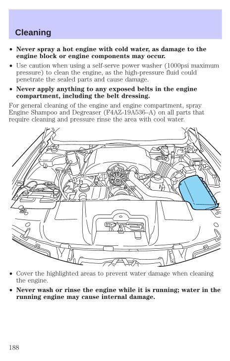
• Never spray a hot engine with cold water, as damage to theengine block or engine components may occur.
• Use caution when using a self-serve power washer (1000psi maximumpressure) to clean the engine, as the high-pressure fluid couldpenetrate the sealed parts and cause damage.
• Never apply anything to any exposed belts in the enginecompartment, including the belt dressing.
For general cleaning of the engine and engine compartment, sprayEngine Shampoo and Degreaser (F4AZ-19A536–A) on all parts thatrequire cleaning and pressure rinse the area with cool water.
• Cover the highlighted areas to prevent water damage when cleaningthe engine.
• Never wash or rinse the engine while it is running; water in therunning engine may cause internal damage.
Cleaning
188
WASHING NON-PAINTED PLASTIC EXTERIOR PARTSUse Detail Wash (ZC-3–A) for routine cleaning.
If tar or grease spots are present, clean with Extra Strength Tar andRoad Oil Removal (B7A-19520–AA).
Use only approved products to clean plastic parts. These productsare available from your authorized Ford, Lincoln or Mercury dealer.
WASHING THE EXTERIOR LAMPSIn order to avoid scratching the plastic lamps, do not use drypaper towels, non-approved chemical solvents or abrasivecleaners.
Use a soft cloth and a solution of Triple Clean (EOAZ-19526–AA), mixedproperly with water, in order to remove bug residue. If tar or greasespots are present, clean with Extra Strength Tar and Road Oil Removal(B7A-19520–AA).
CLEANING THE WINDSHIELD, WIPER BLADES AND REARWINDOWIf the wiper does not wipe properly, substances on the windshield, rearwindow or the wiper blades may be the cause. These may include hotwax treatments used by commercial car washes, tree sap, or otherorganic contamination.
Do not clean the windshield or rear window glass with abrasives,as they may cause scratches.
Do not use fuel, kerosene, or paint thinner to clean thewindshield, rear window or the wiper blades as damage mayoccur.
Clean the outside of the windshield or rear window with a non-abrasivecleaner such as Ultra Clear Spray Glass Cleaner (E4AZ-19C507–AA),available from your authorized Ford, Lincoln or Mercury dealer. If aftercleaning the glass surface, the water sheets from the glass (e.g., does notbead), then the window is clean.
The windshield, rear window and wiper blades should be cleanedregularly. Wiper blades can be cleaned with isopropyl (rubbing) alcoholor windshield washer solution. Be sure to replace wiper blades whenthey appear worn or do not function properly.
Cleaning
189
CLEANING THE INSTRUMENT PANELClean the instrument panel with a damp cloth, then dry with a dry cloth.
Avoid cleaners or polish that increase the gloss of the upper portion ofthe instrument panel. The dull finish in this area helps protect the driverfrom undesirable windshield reflection.
Do not use chemical solvents or strong detergents when cleaningthe steering wheel or instrument panel to avoid contamination of
the air bag system.
Cleaning the instrument cluster lensWipe the cluster area with a soft, damp cotton towel. Dry the area with aclean, dry towel.
CLEANING SEATS EQUIPPED WITH SIDE AIR BAGSRemove dust and loose dirt with a vacuum cleaner. In order to removestains and soil, clean with Extra Strength Upholstery Cleaner(E8AZ-19523–AA).
Never saturate the seat covers with any cleaning solution.
Do not use chemical solvents or strong detergents when cleaningthe seat where the side air bag is mounted. Such products could
contaminate the side air bag system and affect performance of the sideair bag in a collision. The air bag may not function correctly and notprovide injury reduction benefits.
CLEANING THE INTERIOR FABRIC, CARPETS AND CLOTH SEATSRemove dust and loose dirt with a vacuum cleaner. Remove light stainsand soil with Extra Strength Upholstery Cleaner (E8AZ-19523–AA).
Never saturate the seat covers with cleaning solution.
Do not use household cleaning products or glass cleaners, whichcan stain and discolor the fabric and affect the flame retardentabilities of the seat materials.
If grease or tar is present on the material, spot-clean the area first withSpot and Stain Remover (F3AZ-19521–WA). Follow up by recleaning thearea with Extra Strength Upholstery Cleaner (E8AZ-19523–AA).
Cleaning
190

CLEANING LEATHER SEATS (IF EQUIPPED)All Ford, Lincoln and Mercury vehicles with leather seating surfaces havea clear, protective coating over the leather.
To clean the leather seats, simply use a soft cloth with Deluxe Leatherand Vinyl Cleaner (F2AZ-19521–WA). Dry the area with a soft cloth.
It is recommended that you use the Deluxe Leather Care Kit(F8AZ-19G253–AA), available from your authorized Ford, Lincoln orMercury dealer. The mild cleaner and special pad available in the kitcleans the leather and maintains its natural beauty. For best results,follow the instructions printed on the cleaner label. Regular cleaning ofyour leather upholstery helps maintain its resiliency and color.
Do not use household cleaning products, alcohol solutions,solvents or cleaners intended for rubber, vinyl and plastics, oroil/petroleum-based leather conditioners. These products maycause premature wearing of the clear, protective coating.
CLEANING THE INSIDE WINDOWSUse Ultra Clear Spray Glass Cleaner (E4AZ-19C507–AA) for the insidewindows if they become fogged.
To clean, use two lint-free, soft towels, folded into a pad-shape. Mist theglass completely with cleaner, and use one of the towels to evenly agitatethe surface. Use the other towel to remove the residue.
CLEANING AND MAINTAINING THE SAFETY BELTSClean the safety belts with Extra Strength Upholstery Cleaner(E8AZ-19523–AA), available from your authorized Ford, Lincoln orMercury dealer.
Do not use bleach, dye or any other solvent to clean the belts, asthese actions may weaken the belt webbing.
UNDERBODYFlush the complete underside of your vehicle frequently. Keep body anddoor drain holes free from packed dirt.
Cleaning
191

FORD, LINCOLN AND MERCURY CAR CARE PRODUCTSYour Ford, Lincoln or Mercury dealer has many quality products availableto clean your vehicle and protect its finishes. These quality productshave been specifically engineered to fulfill your automotive needs; theyare custom designed to complement the style and appearance of yourvehicle. Each product is made from high quality materials that meet orexceed rigid specifications. For best results, use the following orproducts of equivalent quality:
Ford Custom Clearcoat Polish*
Ford Custom Silicone Gloss Polish
Ford Custom Vinyl Protectant* (not available in Canada)
Motorcraft Vinyl Conditioner (Canada only)
Ford Deluxe Leather and Vinyl Cleaner (not available in Canada)
Motorcraft Vinyl Cleaner (Canada only)
Ford Extra Strength Tar and Road Oil Remover* (not available inCanada)
Ford Extra Strength Upholstery Cleaner (not available in Canada)
Ford Custom Bright Metal Cleaner
Motorcraft Premium Car Wash Concentrate
Motorcraft Carlite Glass Cleaner (Canada only)
Ford Spot and Stain Remover*
Ford Super Premium Tire and Trim Dressing
Ford Triple Clean
Ford Ultra-Clear Spray Glass Cleaner (not available in Canada)
Ford Engine Shampoo and Degreaser
* May be sold with the Motorcraft name
Cleaning
192
SERVICE RECOMMENDATIONSTo help you service your vehicle:
• We highlight do-it-yourself items in the engine compartment for easylocation.
• We provide a scheduled maintenance guide which makes trackingroutine service easy.
If your vehicle requires professional service, your dealership can providethe necessary parts and service. Check your Warranty Guide to find outwhich parts and services are covered.
Use only recommended fuels, lubricants, fluids and service partsconforming to specifications. Motorcraft parts are designed and built toprovide the best performance in your vehicle.
PRECAUTIONS WHEN SERVICING YOUR VEHICLEBe especially careful when inspecting or servicing your vehicle.
• Do not work on a hot engine.
• When the engine is running, keep loose clothing, jewelry or long hairaway from moving parts.
• Do not work on a vehicle with the engine running in an enclosedspace, unless you are sure you have enough ventilation.
• Keep all lit cigarettes, open flames and other lit material away fromthe battery and all fuel related parts.
If you disconnect the battery, the engine must “relearn” its idleconditions before your vehicle will drive properly, as explained in theBattery section in this chapter.
Working with the engine off1. Set the parking brake and ensure the gearshift is securely latched in P(Park).
2. Turn off the engine and remove the key.
3. Block the wheels to prevent the vehicle from moving unexpectedly.
Working with the engine on1. Set the parking brake and ensure the gearshift is securely latched in P(Park).
2. Block the wheels to prevent the vehicle from moving unexpectedly.
Maintenance and Specifications
193
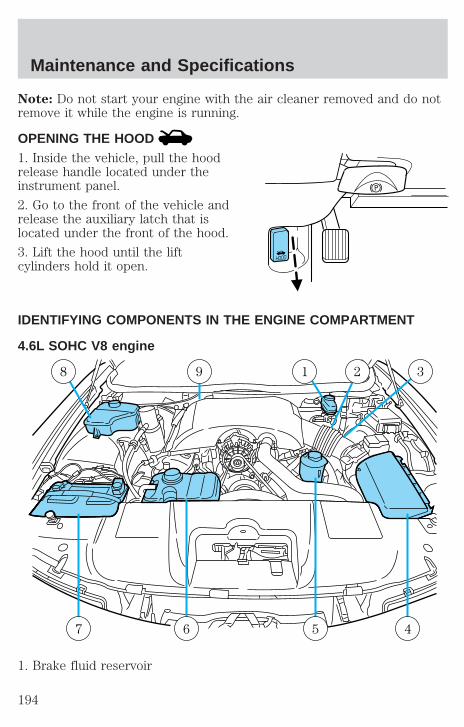
Note: Do not start your engine with the air cleaner removed and do notremove it while the engine is running.
OPENING THE HOOD1. Inside the vehicle, pull the hoodrelease handle located under theinstrument panel.
2. Go to the front of the vehicle andrelease the auxiliary latch that islocated under the front of the hood.
3. Lift the hood until the liftcylinders hold it open.
IDENTIFYING COMPONENTS IN THE ENGINE COMPARTMENT
4.6L SOHC V8 engine
1. Brake fluid reservoir
8 9 1 2 3
6 5 47
Maintenance and Specifications
194
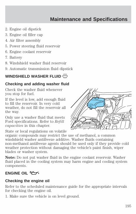
2. Engine oil dipstick
3. Engine oil filler cap
4. Air filter assembly
5. Power steering fluid reservoir
6. Engine coolant reservoir
7. Battery
8. Windshield washer fluid reservoir
9. Automatic transmission fluid dipstick
WINDSHIELD WASHER FLUID
Checking and adding washer fluidCheck the washer fluid wheneveryou stop for fuel.
If the level is low, add enough fluidto fill the reservoir. In very coldweather, do not fill the reservoir allthe way.
Only use a washer fluid that meetsFord specifications. Refer to Refillcapacities in this chapter.
State or local regulations on volatileorganic compounds may restrict the use of methanol, a commonwindshield washer antifreeze additive. Washer fluids containingnon-methanol antifreeze agents should be used only if they provide coldweather protection without damaging the vehicle’s paint finish, wiperblades or washer system.
Note: Do not put washer fluid in the engine coolant reservoir. Washerfluid placed in the cooling system may harm engine and cooling systemcomponents.
ENGINE OIL
Checking the engine oilRefer to the scheduled maintenance guide for the appropriate intervalsfor checking the engine oil.
1. Make sure the vehicle is on level ground.
Maintenance and Specifications
195
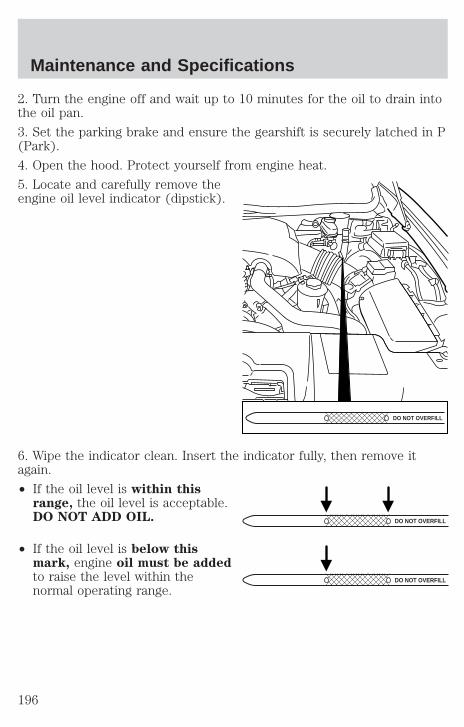
2. Turn the engine off and wait up to 10 minutes for the oil to drain intothe oil pan.
3. Set the parking brake and ensure the gearshift is securely latched in P(Park).
4. Open the hood. Protect yourself from engine heat.
5. Locate and carefully remove theengine oil level indicator (dipstick).
6. Wipe the indicator clean. Insert the indicator fully, then remove itagain.
• If the oil level is within thisrange, the oil level is acceptable.DO NOT ADD OIL.
• If the oil level is below thismark, engine oil must be addedto raise the level within thenormal operating range.
DO NOT OVERFILL
DO NOT OVERFILL
DO NOT OVERFILL
Maintenance and Specifications
196

• If required, add engine oil to theengine. Refer to Adding engineoil in this chapter.
• Do not overfill the enginewith oil. Oil levels above thismark may cause enginedamage. If the engine isoverfilled, some oil must be removed from the engine by a qualifiedservice technician.
7. Put the indicator back in and ensure it is fully seated.
Adding engine oil1. Check the engine oil. For instructions, refer to Checking the engineoil in this chapter.
2. If the engine oil level is not within the normal operating range, addonly certified engine oil of the recommended viscosity. Remove theengine oil filler cap and use a funnel to pour the engine oil into theopening.
3. Recheck the engine oil level. Make sure the oil level is not above thenormal operating range on the engine oil level indicator (dipstick).
4. Install the indicator and ensure it is fully seated.
5. Fully install the engine oil filler cap by turning the filler cap clockwiseuntil three clicks can be heard.
To avoid possible oil loss, DO NOT operate the vehicle with theengine oil level indicator and/or the engine oil filler cap removed.
DO NOT OVERFILL
Maintenance and Specifications
197

Engine oil and filter recommendationsLook for this certificationtrademark.
SAE 5W-20 engine oil is recommended.Only use oils “Certified For Gasoline Engines” by the AmericanPetroleum Institute (API). Use Motorcraft or an equivalent oil meetingFord specification WSS-M2C153–H. SAE 5W-20 oil provides optimumfuel economy and durability performance meeting allrequirements for your vehicle’s engine.
Do not use supplemental engine oil additives, oil treatments or enginetreatments. They are unnecessary and could, under certain conditions,lead to engine damage which is not covered by your warranty.
Change your engine oil and filter according to the appropriate schedulelisted in the scheduled maintenance guide.
Ford production and aftermarket (Motorcraft) oil filters are designed foradded engine protection and long life. If a replacement oil filter is usedthat does not meet Ford material and design specifications, start-upengine noises or knock may be experienced.
It is recommended you use the appropriate Motorcraft oil filter (oranother brand meeting Ford specifications) for your engine application.
Maintenance and Specifications
198
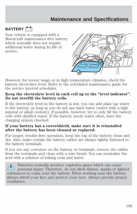
BATTERYYour vehicle is equipped with aMotorcraft maintenance-free batterywhich normally does not requireadditional water during its life ofservice.
However, for severe usage or in high temperature climates, check thebattery electrolyte level. Refer to the scheduled maintenance guide forthe service interval schedules.
Keep the electrolyte level in each cell up to the “level indicator”.Do not overfill the battery cells.
If the electrolyte level in the battery is low, you can add plain tap waterto the battery, as long as you do not use hard water (water with a highmineral or alkali content). If possible, however, try to only fill the batterycells with distilled water. If the battery needs water often, have thecharging system checked.
If your battery has a cover/shield, make sure it is reinstalledafter the battery has been cleaned or replaced.
For longer, trouble-free operation, keep the top of the battery clean anddry. Also, make certain the battery cables are always tightly fastened tothe battery terminals.
If you see any corrosion on the battery or terminals, remove the cablesfrom the terminals and clean with a wire brush. You can neutralize theacid with a solution of baking soda and water.
Batteries normally produce explosive gases which can causepersonal injury. Therefore, do not allow flames, sparks or lighted
substances to come near the battery. When working near the battery,always shield your face and protect your eyes. Always provide properventilation.
Maintenance and Specifications
199
When lifting a plastic-cased battery, excessive pressure on theend walls could cause acid to flow through the vent caps,
resulting in personal injury and/or damage to the vehicle or battery.Lift the battery with a battery carrier or with your hands on oppositecorners.
Keep batteries out of reach of children. Batteries contain sulfuricacid. Avoid contact with skin, eyes or clothing. Shield your eyes
when working near the battery to protect against possible splashing ofacid solution. In case of acid contact with skin or eyes, flushimmediately with water for a minimum of 15 minutes and get promptmedical attention. If acid is swallowed, call a physician immediately.
Battery posts, terminals and related accessories contain lead andlead compounds. Wash hands after handling.
Because your vehicle’s engine is electronically controlled by a computer,some control conditions are maintained by power from the battery. Whenthe battery is disconnected or a new battery is installed, the engine mustrelearn its idle and fuel trim strategy for optimum driveability andperformance. To begin this process:
1. With the vehicle at a complete stop, set the parking brake.
2. Put the gearshift in P (Park), turn off all accessories and start theengine.
3. Run the engine until it reaches normal operating temperature.
4. Allow the engine to idle for at least one minute.
5. Turn the A/C on and allow the engine to idle for at least one minute.
6. With your foot on the brake pedal and with the A/C on, put thevehicle in D (Drive) and allow the engine to idle for at least one minute.
7. Drive the vehicle to complete the relearning process.
• The vehicle may need to be driven 16 km (10 miles) or more torelearn the idle and fuel trim strategy.
• If you do not allow the engine to relearn its idle trim, the idlequality of your vehicle may be adversely affected until the idletrim is eventually relearned.
Maintenance and Specifications
200
If the battery has been disconnected or a new battery has been installed,the clock must be reset once the battery is reconnected.
• Always dispose of automotivebatteries in a responsible manner.Follow your local authorizedstandards for disposal. Call yourlocal authorized recycling centerto find out more about recyclingautomotive batteries.
ENGINE COOLANT
Checking engine coolantThe concentration and level of engine coolant should be checked at themileage intervals listed in the scheduled maintenance guide. The coolantconcentration should be maintained at 50/50 coolant and water, whichequates to a freeze point of -36° C (-34° F). Coolant concentrationtesting is possible with a hydrometer or antifreeze tester (such as theRotunda Battery and Antifreeze Tester, 014–R1060). The level of coolantshould be maintained at the “cold full” of “cold fill range” level in thecoolant reservoir. If the level falls below, add coolant per the instructionsin the Adding Engine Coolant section.
Your vehicle was factory-filled with a 50/50 engine coolant and waterconcentration. If the concentration of coolant falls below 40% or above60%, the engine parts could become damaged or not work properly. A50–50 mixture of coolant and water provides the following:
• Freeze protection down to -36° C (-34° F).
• Boiling protection up to 129° C (265° F).
• Protection against rust and other forms of corrosion.
• Enables calibrated gauges to work properly.
LE
AD
RE
TU
RN
RECYCLE
Maintenance and Specifications
201
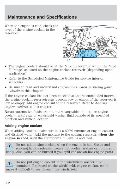
When the engine is cold, check thelevel of the engine coolant in thereservoir.
• The engine coolant should be at the “cold fill level” or within the “coldfill range” as listed on the engine coolant reservoir (depending uponapplication).
• Refer to the Scheduled Maintenance Guide for service intervalschedules.
• Be sure to read and understand Precautions when servicing yourvehicle in this chapter.
If the engine coolant has not been checked at the recommended interval,the engine coolant reservoir may become low or empty. If the reservoir islow or empty, add engine coolant to the reservoir. Refer to Addingengine coolant in this chapter.
Note: Automotive fluids are not interchangeable; do not use enginecoolant, antifreeze or windshield washer fluid outside of its specifiedfunction and vehicle location.
Adding engine coolantWhen adding coolant, make sure it is a 50/50 mixture of engine coolantand distilled water. Add the mixture to the coolant reservoir, when theengine is cool, until the appropriate fill level is obtained.
Do not add engine coolant when the engine is hot. Steam andscalding liquids released from a hot cooling system can burn you
badly. Also, you can be burned if you spill coolant on hot engine parts.
Do not put engine coolant in the windshield washer fluidcontainer. If sprayed on the windshield, engine coolant could
make it difficult to see through the windshield.
Maintenance and Specifications
202
The cooling system in your vehicle is filled with either green-coloredMotorcraft Premium Engine Coolant meeting Ford specificationESE-M97B44–A or yellow-colored Motorcraft Premium Gold EngineCoolant meeting Ford Specification WSS-M97B51–A1. To determine yourvehicle’s coolant type (color), check your coolant reservoir.
• Add Motorcraft Premium Engine Coolant (green-colored),VC-4–A (U.S.) or CXC-10 (Canada) or Motorcraft PremiumGold Engine Coolant (yellow-colored), VC-7–A, depending onthe type of coolant originally equipped in your vehicle. If youare unsure which type of coolant your vehicle requires, check yourcoolant reservoir or contact your local dealer.
• Do not add/mix an orange-colored, extended life coolant suchas Motorcraft Speciality Orange Engine Coolant, VC-2 (US) orCXC-209 (Canada), meeting Ford specification WSS-M97B44–Dwith the factory-filled coolant. Mixing Motorcraft Speciality OrangeEngine Coolant or any orange-colored extended life product with yourfactory filled coolant can result in degraded corrosion protection.
• A large amount of water without engine coolant may be added, in caseof emergency, to reach a vehicle service location. In this instance, thecooling system must be drained and refilled with a 50/50 mixture ofengine coolant and distilled water as soon as possible. Water alone(without engine coolant) can cause engine damage from corrosion,overheating or freezing.
• Do not use alcohol, methanol or brine or any engine coolantsmixed with alcohol or methanol antifreeze (coolant). Alcoholand other liquids can cause engine damage from overheating orfreezing.
• Do not add extra inhibitors or additives to the coolant. Thesecan be harmful and compromise the corrosion protection of the enginecoolant.
• Do not mix with recycled coolant unless from a Ford-approvedrecycling process (see Use of Recycled Engine Coolant section).
For vehicles with overflow coolant systems with a non-pressurized capon the coolant recovery system, add coolant to the coolant recoveryreservoir when the engine is cool. Add the proper mixture of coolant andwater to the “cold full” level. For all other vehicles, which have a coolantdegas system with a pressurized cap, or if it is necessary to remove thecoolant pressure relief cap on the radiator of a vehicle with an overflowsystem, follow these steps to add engine coolant.
Maintenance and Specifications
203
To avoid personal injury, make sure the engine is cool beforeunscrewing the coolant pressure relief cap. The cooling system is
under pressure; steam and hot liquid can come out forcefully when thecap is loosened slightly.
1. Before you begin, turn the engine off and let it cool.
2. When the engine is cool, wrap a thick cloth around the coolantpressure relief cap on the coolant reservoir (an opaque plastic bottle).Slowly turn cap counterclockwise (left) until pressure begins to release.
3. Step back while the pressure releases.
4. When you are sure that all the pressure has been released, use thecloth to turn it counterclockwise and remove the cap.
5. Fill the coolant reservoir slowly with the proper coolant mixture (seeabove), to within the “cold fill range” or the “cold full” level on thereservoir. If you removed the radiator cap in an overflow system, fill theradiator until the coolant is visible and radiator is almost full.
6. Replace the cap. Turn until tightly installed. (Cap must be tightlyinstalled to prevent coolant loss.)
After any coolant has been added, check the coolant concentration seeChecking Engine Coolant section). If the concentration is not 50/50(protection to –34° F/–36° C), drain some coolant and adjust theconcentration. It may take several drains and additions to obtain a 50/50coolant concentration.
Whenever coolant has been added, the coolant level in the coolantreservoir should be checked the next few times you drive the vehicle. Ifnecessary, add enough 50/50 concentration of engine coolant anddistilled water to bring the liquid level to the proper level.
If you have to add more than 1.0 liter (1.0 quart) of engine coolant permonth, have your dealer check the engine cooling system. Your coolingsystem may have a leak. Operating an engine with a low level of coolantcan result in engine overheating and possible engine damage.
Maintenance and Specifications
204
Recycled engine coolantFord Motor Company recommends the use of a recycled engine coolantproduced by Ford-approved processes in vehicles originally equippedwith Motorcraft Premium Engine Coolant (green-colored). However, notall coolant recycling processes produce coolant that meets Fordspecification ESE-M97B44–A. Use of such coolant may harm the engineand cooling system components.
Ford Motor Company does NOT recommend the use of recycled enginecoolant in vehicles originally equipped with Motorcraft Premium GoldEngine Coolant since a Ford-approved recycling process is not yetavailable.
Used engine coolant should be disposed of in an appropriatemanner. Follow your community’s regulations and standards for recyclingand disposing of automotive fluids.
Coolant refill capacityTo find out how much fluid your vehicle’s cooling system can hold, referto Refill capacities in this chapter.
Fill your engine coolant reservoir as outlined in Adding engine coolantin this chapter.
Severe climatesIf you drive in extremely cold climates (less than –36° C [–34° F]):
• It may be necessary to increase the coolant concentrationabove 50%.
• NEVER increase the coolant concentration above 60%.
• Increased engine coolant concentrations above 60% willdecrease the overheat protection characteristics of the enginecoolant and may cause engine damage.
• Refer to the chart on the coolant container to ensure thecoolant concentration in your vehicle will provide adequatefreeze protection at the temperatures in which you drive in thewinter months.
If you drive in extremely hot climates:
• It is still necessary to maintain the coolant concentrationabove 40%.
Maintenance and Specifications
205
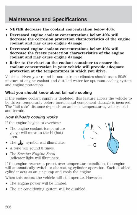
• NEVER decrease the coolant concentration below 40%.
• Decreased engine coolant concentrations below 40% willdecrease the corrosion protection characteristics of the enginecoolant and may cause engine damage.
• Decreased engine coolant concentrations below 40% willdecrease the freeze protection characteristics of the enginecoolant and may cause engine damage.
• Refer to the chart on the coolant container to ensure thecoolant concentration in your vehicle will provide adequateprotection at the temperatures in which you drive.
Vehicles driven year-round in non-extreme climates should use a 50/50mixture of engine coolant and distilled water for optimum cooling systemand engine protection.
What you should know about fail-safe coolingIf the engine coolant supply is depleted, this feature allows the vehicle tobe driven temporarily before incremental component damage is incurred.The “fail-safe” distance depends on ambient temperatures, vehicle loadand terrain.
How fail-safe cooling worksIf the engine begins to overheat:
• The engine coolant temperaturegauge will move to the H (hot)area.
• The symbol will illuminate.
• A tone will sound 3 times.
• The Service Engine Soonindicator light will illuminate.
If the engine reaches a preset over-temperature condition, the enginewill automatically switch to alternating cylinder operation. Each disabledcylinder acts as an air pump and cools the engine.
When this occurs the vehicle will still operate. However:
• The engine power will be limited.
• The air conditioning system will be disabled.
H
Maintenance and Specifications
206

Continued operation will increase the engine temperature:
• The symbol will begin to flash.
• A tone will sound 5 times.
• The engine will completely shut down, causing steering and brakingeffort to increase.
Once the engine temperature cools, the engine can be re-started. Takeyour vehicle to a service facility as soon as possible to minimize enginedamage.
When fail-safe mode is activatedYou have limited engine power when in the fail-safe mode, so drive thevehicle with caution. The vehicle will not be able to maintain high-speedoperation and the engine will run rough. Remember that the engine iscapable of completely shutting down automatically to prevent enginedamage, therefore:
1. Pull off the road as soon as safely possible and turn off the engine.
2. Arrange for the vehicle to be taken to a service facility.
3. If this is not possible, wait a short period for the engine to cool.
4. Check the coolant level and replenish if low.
Never remove the coolant reservoir cap while the engine isrunning or hot.
5. Re-start the engine and take your vehicle to a service facility.
Driving the vehicle without repairing the engine problemincreases the chance of engine damage. Take your vehicle to aservice facility as soon as possible.
WHAT YOU SHOULD KNOW ABOUT AUTOMOTIVE FUELS
Important safety precautions
Do not overfill the fuel tank. The pressure in an overfilled tankmay cause leakage and lead to fuel spray and fire.
Maintenance and Specifications
207

The fuel system may be under pressure. If the fuel filler cap isventing vapor or if you hear a hissing sound, wait until it stops
before completely removing the fuel filler cap. Otherwise, fuel mayspray out and injure you or others.
If you do not use the proper fuel filler cap, excessive pressure orvacuum in the fuel tank may damage the fuel system or cause
the fuel cap to disengage in a collision, which may result in possiblepersonal injury.
Automotive fuels can cause serious injury or death if misused ormishandled.
Gasoline may contain benzene, which is a cancer-causing agent.
Observe the following guidelines when handling automotive fuel:
• Extinguish all smoking materialsand any open flames beforefueling your vehicle.
• Always turn off the vehicle beforefueling.
• Automotive fuels can be harmfulor fatal if swallowed. Fuel such asgasoline is highly toxic and ifswallowed can cause death orpermanent injury. If fuel isswallowed, call a physician immediately, even if no symptoms areimmediately apparent. The toxic effects of fuel may not be visible forhours.
• Avoid inhaling fuel vapors. Inhaling too much fuel vapor of any kindcan lead to eye and respiratory tract irritation. In severe cases,excessive or prolonged breathing of fuel vapor can cause seriousillness and permanent injury.
Maintenance and Specifications
208
• Avoid getting fuel liquid in your eyes. If fuel is splashed in the eyes,remove contact lenses (if worn), flush with water for 15 minutes andseek medical attention. Failure to seek proper medical attention couldlead to permanent injury.
• Fuels can also be harmful if absorbed through the skin. If fuel issplashed on the skin and/or clothing, promptly remove contaminatedclothing and wash skin thoroughly with soap and water. Repeated orprolonged skin contact with fuel liquid or vapor causes skin irritation.
• Be particularly careful if you are taking “Antabuse” or other forms ofdisulfiram for the treatment of alcoholism. Breathing gasoline vapors,or skin contact could cause an adverse reaction. In sensitiveindividuals, serious personal injury or sickness may result. If fuel issplashed on the skin, promptly wash skin thoroughly with soap andwater. Consult a physician immediately if you experience an adversereaction.
When refueling always shut the engine off and never allowsparks or open flames near the filler neck. Never smoke while
refueling. Fuel vapor is extremely hazardous under certain conditions.Care should be taken to avoid inhaling excess fumes.
The flow of fuel through a fuel pump nozzle can produce staticelectricity, which can cause a fire if fuel is pumped into an
ungrounded fuel container.
Use the following guidelines to avoid static build-up when filling anungrounded fuel container:
• Place approved fuel container on the ground.
• DO NOT fill a fuel container while it is in the vehicle (including thecargo area).
• Keep the fuel pump nozzle in contact with the fuel container whilefilling.
• DO NOT use a device that would hold the fuel pump handle in the fillposition.
Fuel Filler CapYour fuel tank filler cap has an indexed design with a 1/8 turn on/offfeature.
Maintenance and Specifications
209
When fueling your vehicle:
1. Turn the engine off.
2. Carefully turn the filler cap counterclockwise 1/8 of a turn until itstops.
3. Pull to remove the cap from the fuel filler pipe.
4. To install the cap, align the tabs on the cap with the notches on thefiller pipe.
5. Turn the filler cap clockwise 1/8 of a turn until it stops.
The “Check Fuel Cap” light illuminates when the ignition is turned to theON position. It will also illuminate when the fuel filler cap is not properlyinstalled. Proper fuel filler cap installation is checked automatically asthe vehicle is driven, but not until after some fuel is used (fuel guagedrops below full). Once the fuel filler cap is properly secured, the “CheckFuel Cap” light will turn off after a short period of driving.
If you must replace the fuel filler cap, replace it with a fuel fillercap that is designed for your vehicle. The customer warranty maybe void for any damage to the fuel tank or fuel system if thecorrect genuine Ford or Motorcraft fuel filler cap is not used.
The fuel system may be under pressure. If the fuel filler cap isventing vapor or if you hear a hissing sound, wait until it stops
before completely removing the fuel filler cap. Otherwise, fuel mayspray out and injure you or others.
If you do not use the proper fuel filler cap, excessive pressure orvacuum in the fuel tank may damage the fuel system or cause
the fuel cap to disengage in a collision, which may result in possiblepersonal injury.
Choosing the right fuelUse only UNLEADED FUEL. The use of leaded fuel is prohibited by lawand could damage your vehicle.
Do not use fuel containing methanol. It can damage critical fuel systemcomponents.
Your vehicle was not designed to use fuel or fuel additives with metalliccompounds, including manganese-based compounds containing MMT.
Maintenance and Specifications
210
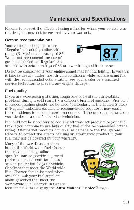
Repairs to correct the effects of using a fuel for which your vehicle wasnot designed may not be covered by your warranty.
Octane recommendationsYour vehicle is designed to use“Regular” unleaded gasoline withpump (R+M)/2 octane rating of 87.We do not recommend the use ofgasolines labeled as “Regular” thatare sold with octane ratings of 86 or lower in high altitude areas.
Do not be concerned if your engine sometimes knocks lightly. However, ifit knocks heavily under most driving conditions while you are using fuelwith the recommended octane rating, see your dealer or a qualifiedservice technician to prevent any engine damage.
Fuel qualityIf you are experiencing starting, rough idle or hesitation driveabilityproblems during a cold start, try a different brand of gasoline. “Premium”unleaded gasoline should not be used (particularly in the United States)if “Regular” unleaded gasoline is recommended because it may causethese problems to become more pronounced. If the problems persist, seeyour dealer or a qualified service technician.
It should not be necessary to add any aftermarket products to your fueltank if you continue to use high quality fuel of the recommended octanerating. Aftermarket products could cause damage to the fuel system.Repairs to correct the effects of using an aftermarket product in yourfuel may not be covered by your warranty.
Many of the world’s automakersissued the World-wide Fuel Charterthat recommends gasolinespecifications to provide improvedperformance and emission controlsystem protection for your vehicle.Gasolines that meet the World-wideFuel Charter should be used whenavailable. Ask your fuel supplierabout gasolines that meet theWorld-wide Fuel Charter. In Canada,look for fuels that display the Auto Makers’ Choicey logo.
87(R+M)/2 METHOD
Maintenance and Specifications
211

Cleaner airFord endorses the use of reformulated “cleaner-burning” gasolines toimprove air quality.
Running out of fuelAvoid running out of fuel because this situation may have an adverseaffect on powertrain components.
If you have run out of fuel:
• You may need to cycle the ignition from OFF to ON several times afterrefueling, to allow the fuel system to pump the fuel from the tank tothe engine.
• Your “Service Engine Soon” indicator may come on. For moreinformation on the “Service Engine Soon” indicator, refer to theInstrument Cluster chapter.
Fuel FilterFor fuel filter replacement, see your dealer or a qualified servicetechnician. Refer to the scheduled maintenance guide for the appropriateintervals for changing the fuel filter.
Replace the fuel filter with an authorized Motorcraft part. Thecustomer warranty may be void for any damage to the fuel systemif an authorized Motorcraft fuel filter is not used.
ESSENTIALS OF GOOD FUEL ECONOMY
Measuring techniquesYour best source of information about actual fuel economy is you, thedriver. You must gather information as accurately and consistently aspossible. Fuel expense, frequency of fillups or fuel gauge readings areNOT accurate as a measure of fuel economy. We do not recommendtaking fuel economy measurements during the first 1 600 km (1 000miles) of driving (engine break-in period). You will get a more accuratemeasurement after 3 000 km–5 000 km (2 000 miles-3 000 miles).
Filling the tankThe advertised fuel capacity of the fuel tank on your vehicle is equal tothe rated refill capacity of the fuel tank as listed in the Refill capacitiessection of this chapter.
Maintenance and Specifications
212

The advertised capacity is the amount of the indicated capacity and theempty reserve combined. Indicated capacity is the difference in theamount of fuel in a full tank and a tank when the fuel gauge indicatesempty. Empty reserve is the small amount of fuel remaining in the fueltank after the fuel gauge indicates empty.
The amount of usable fuel in the empty reserve varies and shouldnot be relied upon to increase driving range. When refueling yourvehicle after the fuel gauge indicates empty, you might not beable to refuel the full amount of the advertised capacity of thefuel tank due to the empty reserve still present in the tank.
For consistent results when filling the fuel tank:
• Turn the engine/ignition switch to the off position prior to refueling,an error in the reading will result if the engine is left running.
• Use the same filling rate setting (low — medium — high) each timethe tank is filled.
• Allow no more than 2 automatic click-offs when filling.
• Always use fuel with the recommended octane rating.
• Use a known quality gasoline, preferably a national brand.
• Use the same side of the same pump and have the vehicle facing thesame direction each time you fill up.
• Have the vehicle loading and distribution the same every time.
Your results will be most accurate if your filling method is consistent.
Calculating fuel economy1. Fill the fuel tank completely and record the initial odometer reading(in kilometers or miles).
2. Each time you fill the tank, record the amount of fuel added (in litersor gallons).
3. After at least three to five tank fill-ups, fill the fuel tank and recordthe current odometer reading.
4. Subtract your initial odometer reading from the current odometerreading.
Maintenance and Specifications
213
5. Follow one of the simple calculations in order to determine fueleconomy:
Multiply liters used by 100, then divide by total kilometerstraveled.
Divide total miles traveled by total gallons used.
Keep a record for at least one month and record the type of driving (cityor highway). This will provide an accurate estimate of the vehicle’s fueleconomy under current driving conditions. Additionally, keeping recordsduring summer and winter will show how temperature impacts fueleconomy. In general, lower temperatures give lower fuel economy.
Driving style — good driving and fuel economy habitsGive consideration to the lists that follow and you may be able to changea number of variables and improve your fuel economy.
Habits• Smooth, moderate operation can yield up to 10% savings in fuel.
• Steady speeds without stopping will usually give the best fueleconomy.
• Idling for long periods of time (greater than one minute) may wastefuel.
• Anticipate stopping; slowing down may eliminate the need to stop.
• Sudden or hard accelerations may reduce fuel economy.
• Slow down gradually.
• Driving at reasonable speeds (traveling at 88 km/h [55 mph] uses 15%less fuel than traveling at 105 km/h [65 mph]).
• Revving the engine before turning it off may reduce fuel economy.
• Using the air conditioner or defroster may reduce fuel economy.
• You may want to turn off the speed control in hilly terrain ifunnecessary shifting between third and fourth gear occurs. Unnecessaryshifting of this type could result in reduced fuel economy.
• Warming up a vehicle on cold mornings is not required and mayreduce fuel economy.
• Resting your foot on the brake pedal while driving may reduce fueleconomy.
• Combine errands and minimize stop-and-go driving.
Maintenance and Specifications
214
Maintenance• Keep tires properly inflated and use only recommended size.
• Operating a vehicle with the wheels out of alignment will reduce fueleconomy.
• Use recommended engine oil. Refer to Lubricant specifications inthis chapter.
• Perform all regularly scheduled maintenance items. Follow therecommended maintenance schedule and owner maintenance checksfound in your vehicle scheduled maintenance guide.
Conditions• Heavily loading a vehicle or towing a trailer may reduce fuel economy
at any speed.
• Carrying unnecessary weight may reduce fuel economy (approximately0.4 km/L [1 mpg] is lost for every 180 kg [400 lb] of weight carried).
• Adding certain accessories to your vehicle (for example bugdeflectors, rollbars/light bars, running boards, ski/luggage racks) mayreduce fuel economy.
• Using fuel blended with alcohol may lower fuel economy.
• Fuel economy may decrease with lower temperatures during the first12–16 km (8–10 miles) of driving.
• Driving on flat terrain offers improved fuel economy as compared todriving on hilly terrain.
• Transmissions give their best fuel economy when operated in the topcruise gear and with steady pressure on the gas pedal.
• Close windows for high speed driving.
EPA window stickerEvery new vehicle should have the EPA window sticker. Contact yourdealer if the window sticker is not supplied with your vehicle. The EPAwindow sticker should be your guide for the fuel economy comparisonswith other vehicles.
It is important to note the box in the lower left corner of the windowsticker. These numbers represent the Range of L/100 km (MPG)expected on the vehicle under optimum conditions. Your fuel economymay vary depending upon the method of operation and conditions.
Maintenance and Specifications
215

EMISSION CONTROL SYSTEMYour vehicle is equipped with various emission control components and acatalytic converter which will enable your vehicle to comply withapplicable exhaust emission standards. To make sure that the catalyticconverter and other emission control components continue to workproperly:
• Use only the specified fuel listed.
• Avoid running out of fuel.
• Do not turn off the ignition while your vehicle is moving, especially athigh speeds.
• Have the items listed in your scheduled maintenance guide performedaccording to the specified schedule.
The scheduled maintenance items listed in the scheduled maintenanceguide are essential to the life and performance of your vehicle and to itsemissions system.
If other than Ford, Motorcraft or Ford-authorized parts are used formaintenance replacements or for service of components affectingemission control, such non-Ford parts should be equivalent to genuineFord Motor Company parts in performance and durability.
Do not park, idle, or drive your vehicle in dry grass or other dryground cover. The emission system heats up the engine
compartment and exhaust system, which can start a fire.
Illumination of the “Service Engine Soon” light, charging system warninglight or the temperature warning light, fluid leaks, strange odors, smokeor loss of engine power, could indicate that the emission control systemis not working properly.
Exhaust leaks may result in entry of harmful and potentiallylethal fumes into the passenger compartment.
Do not make any unauthorized changes to your vehicle or engine. By law,vehicle owners and anyone who manufactures, repairs, services, sells,leases, trades vehicles, or supervises a fleet of vehicles are not permitted tointentionally remove an emission control device or prevent it from working.Information about your vehicle’s emission system is on the VehicleEmission Control Information Decal located on or near the engine. Thisdecal identifies engine displacement and gives some tune up specifications.
Maintenance and Specifications
216
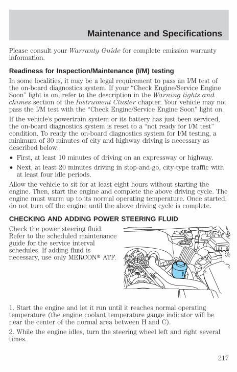
Please consult your Warranty Guide for complete emission warrantyinformation.
Readiness for Inspection/Maintenance (I/M) testingIn some localities, it may be a legal requirement to pass an I/M test ofthe on-board diagnostics system. If your “Check Engine/Service EngineSoon” light is on, refer to the description in the Warning lights andchimes section of the Instrument Cluster chapter. Your vehicle may notpass the I/M test with the “Check Engine/Service Engine Soon” light on.
If the vehicle’s powertrain system or its battery has just been serviced,the on-board diagnostics system is reset to a “not ready for I/M test”condition. To ready the on-board diagnostics system for I/M testing, aminimum of 30 minutes of city and highway driving is necessary asdescribed below:
• First, at least 10 minutes of driving on an expressway or highway.
• Next, at least 20 minutes driving in stop-and-go, city-type traffic withat least four idle periods.
Allow the vehicle to sit for at least eight hours without starting theengine. Then, start the engine and complete the above driving cycle. Theengine must warm up to its normal operating temperature. Once started,do not turn off the engine until the above driving cycle is complete.
CHECKING AND ADDING POWER STEERING FLUIDCheck the power steering fluid.Refer to the scheduled maintenanceguide for the service intervalschedules. If adding fluid isnecessary, use only MERCONt ATF.
1. Start the engine and let it run until it reaches normal operatingtemperature (the engine coolant temperature gauge indicator will benear the center of the normal area between H and C).
2. While the engine idles, turn the steering wheel left and right severaltimes.
Maintenance and Specifications
217
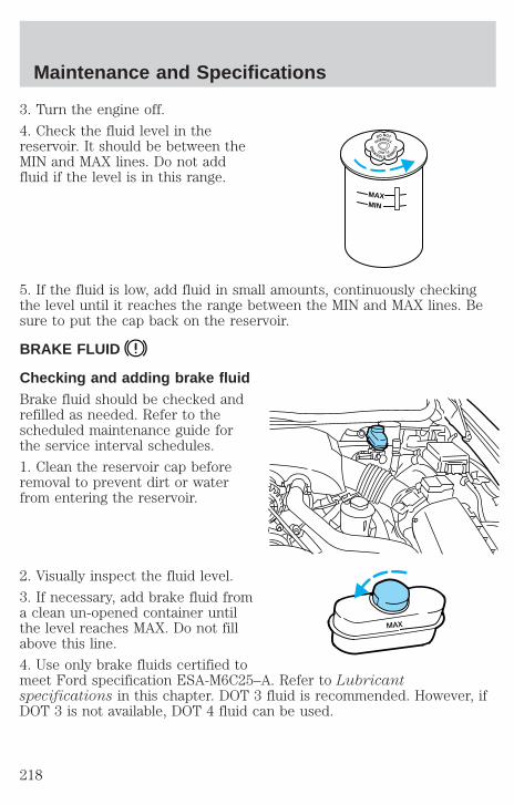
3. Turn the engine off.
4. Check the fluid level in thereservoir. It should be between theMIN and MAX lines. Do not addfluid if the level is in this range.
5. If the fluid is low, add fluid in small amounts, continuously checkingthe level until it reaches the range between the MIN and MAX lines. Besure to put the cap back on the reservoir.
BRAKE FLUID
Checking and adding brake fluidBrake fluid should be checked andrefilled as needed. Refer to thescheduled maintenance guide forthe service interval schedules.
1. Clean the reservoir cap beforeremoval to prevent dirt or waterfrom entering the reservoir.
2. Visually inspect the fluid level.
3. If necessary, add brake fluid froma clean un-opened container untilthe level reaches MAX. Do not fillabove this line.
4. Use only brake fluids certified tomeet Ford specification ESA-M6C25–A. Refer to Lubricantspecifications in this chapter. DOT 3 fluid is recommended. However, ifDOT 3 is not available, DOT 4 fluid can be used.
DO NOT
OVERFILL
PO
W
ERSTEERING FLUID
MAXMIN
MAX
Maintenance and Specifications
218
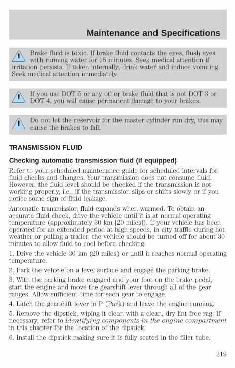
Brake fluid is toxic. If brake fluid contacts the eyes, flush eyeswith running water for 15 minutes. Seek medical attention if
irritation persists. If taken internally, drink water and induce vomiting.Seek medical attention immediately.
If you use DOT 5 or any other brake fluid that is not DOT 3 orDOT 4, you will cause permanent damage to your brakes.
Do not let the reservoir for the master cylinder run dry, this maycause the brakes to fail.
TRANSMISSION FLUID
Checking automatic transmission fluid (if equipped)Refer to your scheduled maintenance guide for scheduled intervals forfluid checks and changes. Your transmission does not consume fluid.However, the fluid level should be checked if the transmission is notworking properly, i.e., if the transmission slips or shifts slowly or if younotice some sign of fluid leakage.
Automatic transmission fluid expands when warmed. To obtain anaccurate fluid check, drive the vehicle until it is at normal operatingtemperature (approximately 30 km [20 miles]). If your vehicle has beenoperated for an extended period at high speeds, in city traffic during hotweather or pulling a trailer, the vehicle should be turned off for about 30minutes to allow fluid to cool before checking.
1. Drive the vehicle 30 km (20 miles) or until it reaches normal operatingtemperature.
2. Park the vehicle on a level surface and engage the parking brake.
3. With the parking brake engaged and your foot on the brake pedal,start the engine and move the gearshift lever through all of the gearranges. Allow sufficient time for each gear to engage.
4. Latch the gearshift lever in P (Park) and leave the engine running.
5. Remove the dipstick, wiping it clean with a clean, dry lint free rag. Ifnecessary, refer to Identifying components in the engine compartmentin this chapter for the location of the dipstick.
6. Install the dipstick making sure it is fully seated in the filler tube.
Maintenance and Specifications
219
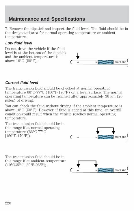
7. Remove the dipstick and inspect the fluid level. The fluid should be inthe designated area for normal operating temperature or ambienttemperature.
Low fluid levelDo not drive the vehicle if the fluidlevel is at the bottom of the dipstickand the ambient temperature isabove 10°C (50°F).
Correct fluid levelThe transmission fluid should be checked at normal operatingtemperature 66°C-77°C (150°F-170°F) on a level surface. The normaloperating temperature can be reached after approximately 30 km (20miles) of driving.
You can check the fluid without driving if the ambient temperature isabove 10°C (50°F). However, if fluid is added at this time, an overfillcondition could result when the vehicle reaches normal operatingtemperature.
The transmission fluid should be inthis range if at normal operatingtemperature (66°C-77°C[150°F-170°F]).
The transmission fluid should be inthis range if at ambient temperature(10°C-35°C [50°F-95°F]).
DON’T ADD
DON’T ADD
DON’T ADD
Maintenance and Specifications
220

High fluid levelFluid levels above the safe rangemay result in transmission failure.An overfill condition of transmissionfluid may cause shift and/orengagement concerns and/orpossible damage.
High fluid levels can be caused byan overheating condition.
Adjusting automatic transmission fluid levelsBefore adding any fluid, make sure the correct type is used. The type offluid used is normally indicated on the dipstick and also in theLubricant specifications section in this chapter.
Use of a non-approved automatic transmission fluid may causeinternal transmission component damage.
If necessary, add fluid in 250 ml (1/2 pint) increments through the fillertube until the level is correct.
If an overfill occurs, excess fluidshould be removed by a qualifiedtechnician.
An overfill condition oftransmission fluid may causeshift and/or engagementconcerns and/or possibledamage.
AIR FILTER MAINTENANCERefer to the scheduled maintenance guide for the appropriate intervalsfor changing the air filter element.
When changing the air filter element, use only the Motorcraft air filterelement listed. Refer to Motorcraft Part Numbers.
Note: Do not start your engine with the air cleaner removed and do notremove it while the engine is running.
Changing the air filter element1. Loosen the clamp that secures the air inlet tube to the engine air filtercover and disconnect the tube from the cover.
DON’T ADD
DON’T ADD
Maintenance and Specifications
221

2. Release the clamps that secure the air filter housing cover.
3. Carefully separate the two halves of the air filter housing.
4. Remove the air filter element from the air filter housing.
5. Wipe the air filter housing and cover clean to remove any dirt ordebris and to ensure good sealing.
6. Install a new air filter element. Becareful not to crimp the filterelement edges between the air filterhousing and cover. This could causefilter damage and allow unfilteredair to enter the engine if notproperly seated.
7. Replace the air filter housing cover and secure the clamps.
8. Replace the air inlet tube and secure the clamp.
Note: Failure to use the correct air filter element may result in severeengine damage. The customer warranty may be voided for any damage tothe engine if the correct air filter element is not used.
INFORMATION ABOUT UNIFORM TIRE QUALITY GRADINGNew vehicles are fitted with tiresthat have a rating on them calledTire Quality Grades. The Qualitygrades can be found whereapplicable on the tire sidewallbetween tread shoulder andmaximum section width. Forexample:
• Treadwear 200 Traction AA Temperature A
These Tire Quality Grades are determined by standards that the UnitedStates Department of Transportation has set.
Tire Quality Grades apply to new pneumatic tires for use on passengercars. They do not apply to deep tread, winter-type snow tires,space-saver or temporary use spare tires, tires with nominal rimdiameters of 10 to 12 inches or limited production tires as defined inTitle 49 Code of Federal Regulations Part 575.104(c)(2).
Maintenance and Specifications
222

U.S. Department of Transportation-Tire quality grades: The U.S.Department of Transportation requires Ford to give you the followinginformation about tire grades exactly as the government has written it.
TreadwearThe treadwear grade is a comparative rating based on the wear rate ofthe tire when tested under controlled conditions on a specifiedgovernment test course. For example, a tire graded 150 would wear oneand one-half (1 1/2) times as well on the government course as a tiregraded 100. The relative performance of tires depends upon the actualconditions of their use, however, and may depart significantly from thenorm due to variations in driving habits, service practices, anddifferences in road characteristics and climate.
Traction AA A B CThe traction grades, from highest to lowest are AA, A, B, and C. Thegrades represent the tire’s ability to stop on wet pavement as measuredunder controlled conditions on specified government test surfaces ofasphalt and concrete. A tire marked C may have poor tractionperformance.
The traction grade assigned to this tire is based onstraight-ahead braking traction tests, and does not include
acceleration, cornering, hydroplaning or peak traction characteristics.
Temperature A B CThe temperature grades are A (the highest), B, and C, representing thetire’s resistance to the generation of heat and its ability to dissipate heatwhen tested under controlled conditions on a specified indoor laboratorytest wheel. Sustained high temperature can cause the material of the tireto degenerate and reduce tire life, and excessive temperature can lead tosudden tire failure. The grade C corresponds to a level of performancewhich all passenger car tires must meet under the Federal Motor VehicleSafety Standard No. 109. Grades B and A represent higher levels ofperformance on the laboratory test wheel than the minimum required bylaw.
Maintenance and Specifications
223
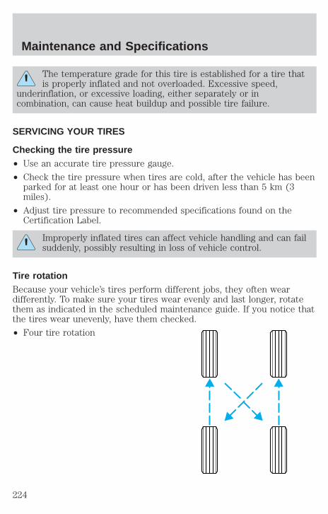
The temperature grade for this tire is established for a tire thatis properly inflated and not overloaded. Excessive speed,
underinflation, or excessive loading, either separately or incombination, can cause heat buildup and possible tire failure.
SERVICING YOUR TIRES
Checking the tire pressure• Use an accurate tire pressure gauge.
• Check the tire pressure when tires are cold, after the vehicle has beenparked for at least one hour or has been driven less than 5 km (3miles).
• Adjust tire pressure to recommended specifications found on theCertification Label.
Improperly inflated tires can affect vehicle handling and can failsuddenly, possibly resulting in loss of vehicle control.
Tire rotationBecause your vehicle’s tires perform different jobs, they often weardifferently. To make sure your tires wear evenly and last longer, rotatethem as indicated in the scheduled maintenance guide. If you notice thatthe tires wear unevenly, have them checked.
• Four tire rotation
Maintenance and Specifications
224
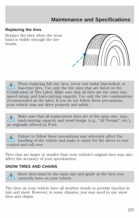
Replacing the tiresReplace the tires when the wearband is visible through the tiretreads.
When replacing full size tires, never mix radial bias-belted, orbias-type tires. Use only the tire sizes that are listed on the
Certification or Tire Label. Make sure that all tires are the same size,speed rating, and load-carrying capacity. Use only the tire combinationsrecommended on the label. If you do not follow these precautions,your vehicle may not drive properly and safely.
Make sure that all replacement tires are of the same size, type,load-carrying capacity and tread design (e.g., “All Terrain”, etc.),
as originally offered by Ford.
Failure to follow these precautions may adversely affect thehandling of the vehicle and make it easier for the driver to lose
control and roll over.
Tires that are larger or smaller than your vehicle’s original tires may alsoaffect the accuracy of your speedometer.
SNOW TIRES AND CHAINS
Snow tires must be the same size and grade as the tires youcurrently have on your vehicle.
The tires on your vehicle have all weather treads to provide traction inrain and snow. However, in some climates, you may need to use snowtires and chains.
Maintenance and Specifications
225
Follow these guidelines when using snow tires and chains:
• Use only cable type chains offered by Ford as an accessory orequivalent. Using SAE class S or other conventional link type chainsmay cause damage to the vehicle’s wheel house and/or body.
• Install chains securely, verifying that the chains do not touch anywiring, brake lines or fuel lines.
• Drive cautiously. If you hear the chains rub or bang against yourvehicle, stop and re-tighten the chains. If this does not work, removethe chains to prevent damage to your vehicle.
• If possible, avoid fully loading your vehicle.
• Remove the tire chains when they are no longer needed. Do not usetire chains on dry roads.
• The suspension insulation and bumpers will help prevent vehicledamage. Do not remove these components from your vehicle whenusing snow tires and chains.
MOTORCRAFT PART NUMBERS
Component 4.6L SOHC V8 engine
Air filter element FA-1668Fuel filter FG-986BBattery-standard BXT-65-650Battery-heavy duty 1 BXT-65-750Oil filter FL-820-SPCV valve EV-98Spark plugs 2 AWSF-32P
1Included in long wheelbase package.2Refer to Vehicle Emissions Control Information (VECI) decal for sparkplug gap information.
Maintenance and Specifications
226
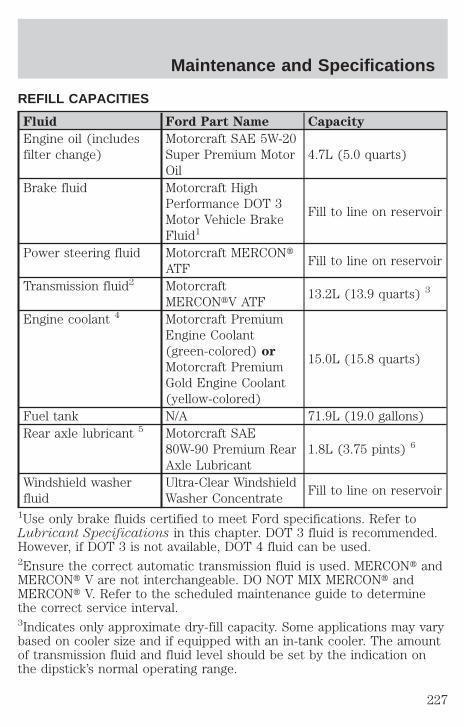
REFILL CAPACITIES
Fluid Ford Part Name Capacity
Engine oil (includesfilter change)
Motorcraft SAE 5W-20Super Premium MotorOil
4.7L (5.0 quarts)
Brake fluid Motorcraft HighPerformance DOT 3Motor Vehicle BrakeFluid1
Fill to line on reservoir
Power steering fluid Motorcraft MERCONtATF
Fill to line on reservoir
Transmission fluid2 MotorcraftMERCONtV ATF
13.2L (13.9 quarts) 3
Engine coolant 4 Motorcraft PremiumEngine Coolant(green-colored) or
Motorcraft PremiumGold Engine Coolant(yellow-colored)
15.0L (15.8 quarts)
Fuel tank N/A 71.9L (19.0 gallons)Rear axle lubricant 5 Motorcraft SAE
80W-90 Premium RearAxle Lubricant
1.8L (3.75 pints) 6
Windshield washerfluid
Ultra-Clear WindshieldWasher Concentrate
Fill to line on reservoir
1Use only brake fluids certified to meet Ford specifications. Refer toLubricant Specifications in this chapter. DOT 3 fluid is recommended.However, if DOT 3 is not available, DOT 4 fluid can be used.2Ensure the correct automatic transmission fluid is used. MERCONt andMERCONt V are not interchangeable. DO NOT MIX MERCONt andMERCONt V. Refer to the scheduled maintenance guide to determinethe correct service interval.3Indicates only approximate dry-fill capacity. Some applications may varybased on cooler size and if equipped with an in-tank cooler. The amountof transmission fluid and fluid level should be set by the indication onthe dipstick’s normal operating range.
Maintenance and Specifications
227

4Add the coolant type originally equipped in your vehicle.5Rear axles are considered lubricated for life when the vehicle is used fornormal service. See your scheduled maintenance guide for Severe Dutyrequirements.6Add 118 ml (4 oz.) of Additive Friction Modifier C8AZ-19B546-A orequivalent meeting Ford specification EST-M2C118–A for complete refillof Traction-Lok rear axle.
For limousine, use 2.4L (5.0 pints) of Motorcraft SAE 75W-140 SyntheticRear Axle Lubricant or equivalent meeting Ford specificationWSL-M2C192-A for complete refill of rear axle.
Service refill capacities are determined by filling the rear axle 6 mm to14 mm (1/4 inch to 9/16 inch) below the bottom of the filler hole.
LUBRICANT SPECIFICATIONS
Item Ford part
name
Ford part
number
Ford
specification
Brake fluid Motorcraft HighPerformanceDOT 3 MotorVehicle BrakeFluid 1
PM-1 ESA-M6C25-Aand DOT 3
Doorweatherstrips
SiliconeLubricant
F7AZ-19G208-BAandF5AZ-19553-AA
ESR-M13P4-A
Engine coolant MotorcraftPremium EngineCoolant (greencolored)
VC-4–A (US) orCXC-10(Canada)
ESE-M97B44-A
MotorcraftPremium GoldEngine Coolant(yellow colored)
VC-7–A WSS-M97B51-A1
Engine oil Motorcraft SAE5W20 SuperPremium MotorOil
XO-5W20-QSP WSS-M2C153-Hwith APICertificationMark
Maintenance and Specifications
228

Item Ford part
name
Ford part
number
Ford
specification
Hinges, latches,striker plates,fuel filler doorhinge and seattracks
Multi-PurposeGrease
XG-4 orF5AZ-19G209-AA
ESB-M1C93-B orESR-M1C159-A
Lock cylinders Penetrating andLock Lubricant
Motorcraft XL-1 N/A
Power steeringfluid
MotorcraftMERCONt ATF
XT-2-QDX MERCONt
Automatictransmission(4R70W)3
MotorcraftMERCONtVATF
XT-5-QMMERCONtV
Rear AxleLubricant 2
Motorcraft SAE80W-90Premium RearAxle Lubricant
XY-80W90-QL WSP-M2C197-A
Windshieldwasher fluid
Ultra-clearWindshieldWasherConcentrate
C9AZ-19550-AC ESR-M17P5-A
1Use only brake fluids certified to meet Ford specifications. DOT 3 fluid isrecommended. However, if DOT 3 is not available, DOT 4 fluid can be used.2Add 118 ml (4 oz.) of Additive Friction Modifier C8AZ-19B546-A orequivalent meeting Ford specification EST-M2C118-A for complete refillof Traction-Lok rear axles.
For limousine, use 2.2–2.4L (4.75–5.0 pints) of Motorcraft SAE75W-140Synthetic High Performance Rear Axle Lubricant XY-75W140–QLor equivalent meeting Ford Specification WSL-M2C192-A for completerefill of rear axles.3Ensure the correct transmission fluid is used. Transmission fluidrequirements are indicated on the dipstick or the dipstick handle.MERCONt and MERCONt V are not interchangeable. DO NOT mixMERCONt and MERCONt V. Refer to your scheduled maintenance guideto determine the correct service interval.
Maintenance and Specifications
229
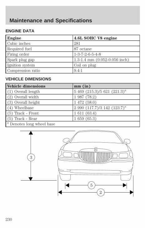
ENGINE DATA
Engine 4.6L SOHC V8 engine
Cubic inches 281Required fuel 87 octaneFiring order 1-3-7-2-6-5-4-8Spark plug gap 1.3-1.4 mm (0.052-0.056 inch)Ignition system Coil on plugCompression ratio 9.4:1
VEHICLE DIMENSIONS
Vehicle dimensions mm (in)
(1) Overall length 5 469 (215.3)/5 621 (221.3)a
(2) Overall width 1 987 (78.2)(3) Overall height 1 472 (58.0)(4) Wheelbase 2 990 (117.7)/3 142 (123.7)a
(5) Track - Front 1 611 (63.4)(5) Track - Rear 1 659 (65.3)a Denotes long wheel base
2
5
3
Maintenance and Specifications
230
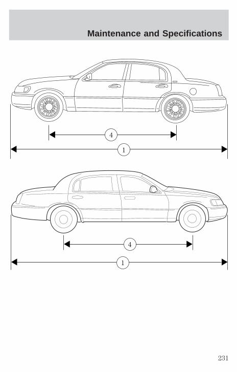
1
4
1
4
Maintenance and Specifications
231
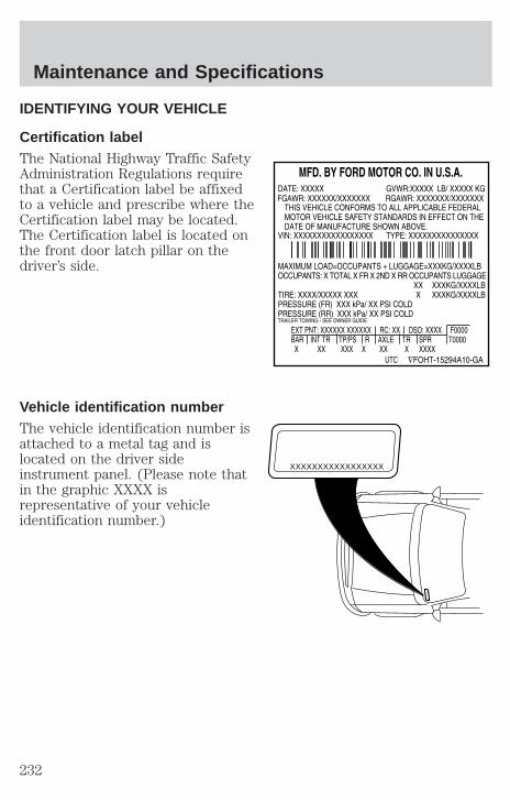
IDENTIFYING YOUR VEHICLE
Certification labelThe National Highway Traffic SafetyAdministration Regulations requirethat a Certification label be affixedto a vehicle and prescribe where theCertification label may be located.The Certification label is located onthe front door latch pillar on thedriver’s side.
Vehicle identification numberThe vehicle identification number isattached to a metal tag and islocated on the driver sideinstrument panel. (Please note thatin the graphic XXXX isrepresentative of your vehicleidentification number.)
XXXXXXXXXXXXXXXXX
Maintenance and Specifications
232
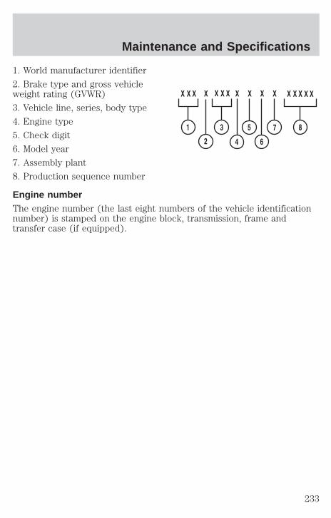
1. World manufacturer identifier
2. Brake type and gross vehicleweight rating (GVWR)
3. Vehicle line, series, body type
4. Engine type
5. Check digit
6. Model year
7. Assembly plant
8. Production sequence number
Engine numberThe engine number (the last eight numbers of the vehicle identificationnumber) is stamped on the engine block, transmission, frame andtransfer case (if equipped).
Maintenance and Specifications
233
FORD ACCESSORIES FOR YOUR VEHICLE
A wide selection of genuine Ford accessories are available for yourvehicle through your local authorized Lincoln Mercury dealer. Thesequality accessories have been specifically engineered to fulfill yourautomotive needs; they are custom designed to complement the styleand aerodynamic appearance of your vehicle. In addition, each accessoryis made from high quality materials and meets or exceeds Ford’s rigorousengineering and safety specifications. Ford Motor Company will repair orreplace any properly dealer-installed Ford accessory found to bedefective in factory-supplied materials or workmanship during thewarranty period, as well as any component damaged by the defectiveaccessory. The accessory will be warranted for whichever provides youthe greatest benefit:
• 12 months or 20 000 km (12 000 miles) (whichever occurs first), or
• The remainder of your new vehicle limited warranty.
This means that genuine Ford accessories purchased along with yournew vehicle and installed by the dealer are covered for the full length ofyour New Vehicle’s Limited Warranty — 3 years or 60 000 km (36 000miles) (whichever occurs first). Contact your dealer for details and acopy of the warranty.
Not all accessories are available for all models.
Vehicle SecurityAir bag anti-theft locks
Locking gas cap
Remote keyless entry
Styled wheel locks
Underbody security lighting
Vehicle security systems
Accessories
234

Comfort and convenienceCargo nets
Cargo organizer
Electrochromic compass mirror
Electrochromic compass mirror with temperature display
Engine block heaters
HomeLinkt
Remote start system
Travel equipmentAutomatic headlamps with daytime running lights (DRL)
Chrome wheel arch molding
Daytime running lights (DRL)
HomeLinkt
Protection and appearance equipmentCarpet floor mats
Door edge guards
First aid kit
Flat splash guards
Front end covers
Highway safety kit
Locking gas cap
Molded splash guards
Styled hood deflector
Universal floor mats
Accessories
235
For maximum vehicle performance, keep the following information inmind when adding accessories or equipment to your vehicle:
• When adding accessories, equipment, passengers and luggage to yourvehicle, do not exceed the total weight capacity of the vehicle or ofthe front or rear axle (GVWR or GAWR as indicated on the Safetycompliance certification label). Consult your dealer for specific weightinformation.
• The Federal Communications Commission (FCC) and Canadian RadioTelecommunications Commission (CRTC) regulate the use of mobilecommunications systems - such as two-way radios, telephones andtheft alarms - that are equipped with radio transmitters. Any suchequipment installed in your vehicle should comply with FCC or CRTCregulations and should be installed only by a qualified servicetechnician.
• Mobile communications systems may harm the operation of yourvehicle, particularly if they are not properly designed for automotiveuse or are not properly installed. When operated, such systems maycause the engine to stumble or stall or cause the transmission to bedamaged or operate improperly. In addition, such systems may bedamaged or their performance may be affected by operating yourvehicle. (Citizens band [CB] transceivers, garage door openers andother transmitters with outputs of five watts or less will not ordinarilyaffect your vehicle’s operation.)
• Ford cannot assume responsibility for any adverse effects or damagethat may result from the use of such equipment.
Accessories
236
A
Accessory delay ..........................62
Air bag supplemental restraintsystem ................................121, 125
and child safety seats ............123description ......................121, 125disposal ....................................128driver air bag ..................123, 126indicator light ...................12, 125operation .........................123, 126passenger air bag ...........123, 126side air bag ..............................125
Air cleaner filter ...............221, 226
Air conditioningautomatic temperaturecontrol system ..........................43
Air suspension ...........................145description ..............................145warning light .............................14
Antifreeze (see Enginecoolant) .....................................201
Anti-lock brake system (seeBrakes) ......................................141
Automatic transmissiondriving an automaticoverdrive .................................147fluid, adding ............................219fluid, checking ........................219fluid, refill capacities ..............227fluid, specification ..................230
Auxiliary power point .................62
Axlelubricant specifications ..228, 230refill capacities ........................227traction lok ..............................149
B
Battery .......................................199acid, treating emergencies .....199charging system warninglight ............................................12jumping a disabled battery ....169maintenance-free ....................199replacement, specifications ...226servicing ..................................199
Belt minder ...............................116
Brakes ........................................140anti-lock ...................................141anti-lock brake system (ABS)warning light .....................12, 142brake warning light ..................12fluid, checking and adding ....218fluid, refill capacities ..............227fluid, specifications .........228, 230lubricantspecifications ..................228, 230pedals (see Power adjustablefoot pedals) ...............................64shift interlock ..........................146
Break-in period .............................6
C
Capacities for refilling fluids ....227
Cassette tape player ...................26
CD changer .................................38
Certification Label ....................232
Child safety restraints ..............129child safety belts ....................129
Child safety seats ..............129–130attaching with tetherstraps .......................................133
Index
237
in front seat ............................131in rear seat ..............................131
Cleaning your vehicleengine compartment ..............187exterior ....................................191instrument cluster lens ..........190instrument panel ....................190interior .....................................190plastic parts ............................189safety belts ..............................191washing ....................................186waxing .....................................186wheels ......................................187windows ..................................191wiper blades ............................189
Clock ................................22, 32, 61
Compass, electronic ....................63calibration .................................79set zone adjustment ...........78–79
Consolerear ............................................85
Controlspower seat ...............................103steering column ........................68
Coolantchecking and adding ..............201coolant temperature light ........13refill capacities ................205, 227specifications ..................228, 230
Cruise control (see Speedcontrol) ........................................65
Customer Assistance ................156Ford accessories for yourvehicle .............................192, 234Ford Extended ServicePlan ..........................................178Getting assistance outside theU.S. and Canada .....................182Getting roadside assistance ...156
Getting the service youneed .........................................176Ordering additional owner’sliterature .................................183The Dispute SettlementBoard .......................................179Utilizing theMediation/ArbitrationProgram ...................................182
D
Daytime running lamps (seeLamps) .........................................49
Defrostrear window ..............................48
Dipstickautomatic transmissionfluid ..........................................219engine oil .................................195
Doorsdoor ajar warning .....................15lubricant specifications ..........228
Driving under specialconditions
through water .........................149
E
Emergencies, roadsidejump-starting ..........................169
Emission control system ..........216
Engine ........................................230check engine/service enginesoon light ..................................10cleaning ...................................187coolant .....................................201fail-safe coolant ......................206idle speed control ...................199
Index
238
lubricationspecifications ..................228, 230refill capacities ........................227service points ..........................194starting after a collision .........157
Engine block heater .................139
Engine oil ..................................195change oil soon warning,message center .......................195checking and adding ..............195dipstick ....................................195filter, specifications ........198, 226recommendations ...................198refill capacities ........................227specifications ..................228, 230
Exhaust fumes ..........................139
F
Fail safe cooling ........................206
Floor mats ...................................87
Fluid capacities .........................227
Fuel ............................................207calculating fueleconomy ............................80, 212cap .....................................11, 209capacity ...................................227choosing the right fuel ...........210comparisons with EPA fueleconomy estimates .................215detergent in fuel .....................212filling your vehicle withfuel ...........................207, 209, 212filter, specifications ........212, 226fuel filler door override ............84fuel filler door release ..............84fuel pump shut-off switch .....157gauge .........................................18improving fuel economy ........212
octane rating ...................211, 230quality ......................................211running out of fuel .................212safety information relating toautomotive fuels .....................207
Fuses ..................................158–159
G
Garage door opener ....................69
Gas cap (see Fuel cap) ......11, 209
Gas mileage (see Fueleconomy) ...................................212
Gauges .........................................17engine coolant temperaturegauge .........................................17fuel gauge ..................................18odometer ...................................18speedometer .............................18
GAWR (Gross Axle WeightRating) .......................................150
definition .................................150driving with a heavy load ......150location ....................................150
GVWR (Gross Vehicle WeightRating) .......................................150
calculating ...............................150definition .................................150driving with a heavy load ......150location ....................................150
H
Hazard flashers .........................157
Head restraints .........................102
Headlamps ...................................49aiming ..................................51–52autolamp system .......................49
Index
239

bulb specifications ....................54daytime running lights .............49flash to pass ..............................50high beam ...........................15, 50replacing bulbs .........................55turning on and off ....................49warning chime ..........................16
HomeLink universaltransceiver (see Garage dooropener) ..................................69–72
Hood ..........................................194
I
Ignition ...............................136, 230
Infant seats(see Safety seats) .............129–130
Inspection/maintenance (I/M)testing ........................................217
Instrument panelcleaning ...................................190cluster ................................10, 190lighting up panel andinterior .......................................50
J
Jack ............................................165positioning ...............................165storage .....................................165
Jump-starting your vehicle ......169
K
Keyless entry system .................96autolock .....................................94keypad .......................................96programming entry code .........96
Keys ...............................88, 98–100key in ignition chime ...............16positions of the ignition .........136
L
Lampsautolamp system .......................49bulb replacementspecifications chart ..................54cargo lamps ...............................50daytime running light ...............49headlamps .................................49headlamps, flash to pass ..........50instrument panel, dimming .....50interior lamps .....................53–54replacing bulbs .......53, 55, 57–58
Lane change indicator (seeTurn signal) .................................53
Lights, warning and indicator ....10air bag ........................................12air suspension ...........................14anti-lock brakes (ABS) ....12, 142brake ..........................................12charging system ........................12cruise indicator .........................14door ajar ....................................15fuel cap light .............................11high beam .................................15liftgate ajar ................................16low coolant ................................13low washer fluid .......................14oil pressure ...............................13safety belt .................................12service engine soon ..................10speed control ............................68traction control system ............15turn signal indicator .................15
Index
240

Load limits .................................150GAWR ......................................150GVWR ......................................150trailer towing ..........................150
Locksautolock .....................................94childproof ..................................88doors ..........................................88
Lubricant specifications ...228, 230
Lumbar support, seats .............103
M
Message center ...........................77english/metric button ...............82reset button ..............................78
Mirrors .........................................61automatic dimming rearviewmirror ........................................63heated ........................................64programmable memory ............94side view mirrors (power) .......63
Moon roof ....................................69
Motorcraft parts ................212, 226
O
Octane rating ............................211
Odometer .....................................18
Oil (see Engine oil) ..................195
Overdrive .............................83, 148
P
Panic alarm feature, remoteentry system ................................91
Parking brake ............................142
Parts (see Motorcraft parts) ....226
Passenger OccupantClassification Sensor .................108
Pedals (see Power adjustablefoot pedals) .................................64
Power distribution box(see Fuses) ...............................163
Power door locks ........................88
Power steering ..................144–145fluid, checking and adding ....217fluid, refill capacity ................227fluid, specifications .........228, 230
R
Rear window defroster ...............48
Relays ........................................158
Remote entry system ...........90–91illuminated entry ......................93locking/unlocking doors ...........90opening the trunk .....................91panic alarm ...............................91replacement/additionaltransmitters ...............................93replacing the batteries .............92
S
Safety belts (see Safetyrestraints) ............16, 106, 110–114
Safety defects, reporting ..........185
Safety restraints ........106, 110–114belt minder .............................116cleaning the safetybelts .................................120, 191extension assembly ................120for adults .........................111–113for children .....................128–129
Index
241

lap belt ....................................114Occupant ClassificationSensor ......................................108warning light andchime ...................12, 16, 115–116
Safety seats forchildren ..............................129–130
Seat belts (see Safetyrestraints) ..................................106
Seats ..........................................102child safety seats ............129–130cleaning ...................................190easy access/easyout feature ..105heated ......................................105memory seat ...............84, 94, 106
SecuriLock passive anti-theftsystem ..................................98–100
Servicing your vehicle ..............193
Spark plugs,specifications .....................226, 230
Specification chart,lubricants ...........................228, 230
Speed control ..............................65
Speedometer ...............................18
Starting your vehicle ........136–138jump starting ..........................169
Steeringspeed sensitive .......................145
Steering wheelcontrols ..........................60, 65, 68tilting .........................................60
T
Tires ...........................165, 222–224
changing ..........................165–166checking the pressure ............224replacing ..................................225rotating ....................................224snow tires and chains ............225tire grades ...............................223treadwear ................................223
Towing .......................................151recreational towing .................154trailer towing ..........................151wrecker ....................................175
Traction control ........................143active light ................................13how to enable/disable ............144off light ......................................14
Traction-lok rear axle ...............149
Transmission .............................146fluid, checking and adding(automatic) .............................219fluid, refill capacities ..............227lubricantspecifications ..................228, 230
Trunk ...........................................89remote release ....................83, 91
Turn signal ......................15–16, 53
V
Vehicle CommunicationSystem .........................................73
Vehicle dimensions ...................230
Vehicle Identification Number(VIN) ..........................................232
Vehicle loading ..........................150
Ventilating your vehicle ...........140
Index
242

W
Warning chimes ...........................16
Warning lights (see Lights) .......10
Washer fluid ..............................195
Water, Driving through .............149
Windowspower .........................................62
Windshield washer fluid andwipers
checking and adding fluid .....195checking and cleaning ..............59operation ...................................59replacing wiper blades .............60
Wrecker towing .........................175
Index
243

244

245

246

247

248