Embed Size (px)
Citation preview
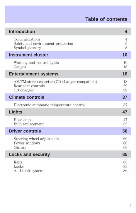
Introduction 4
Congratulations 4Safety and environment protection 5Symbol glossary 8
Instrument cluster 10
Warning and control lights 10Gauges 15
Entertainment systems 18
AM/FM stereo cassette (CD changer compatible) 18Rear seat controls 29CD changer 32
Climate controls 37
Electronic automatic temperature control 37
Lights 47
Headlamps 47Bulb replacement 52
Driver controls 58
Steering wheel adjustment 60Power windows 66Mirrors 68
Locks and security 85
Keys 85Locks 85Anti-theft system 86
Table of contents
1

Seating and safety restraints 99
Seating 99Safety restraints 112Air bags 124Child restraints 132
Driving 142
Starting 142Brakes 146Transmission operation 153Vehicle loading 170Trailer towing 172Recreational towing 176
Roadside emergencies 177
Hazard flasher switch 178Fuses and relays 180Changing tires 188Jump starting 194Wrecker towing 199
Customer assistance 200
The dispute settlement board 203Utilizing the mediation/arbitration 206Getting assistance outside the U.S. and Canada 206Ordering additional owner’s literature 207Reporting safety defects (U.S. only) 209
Cleaning 210
Cleaning your vehicle 210Underbody preservation 215
Table of contents
2

Maintenance and specifications 217
Hood 218Engine compartment 219Engine oil 220Battery 223Fuel information 232Air filter(s) 246Part numbers 252Refill capacities 253Lubricant specifications 255Engine data 257Vehicle dimensions 258
Accessories 261
Index 264
All rights reserved. Reproduction by any means, electronic or mechanicalincluding photocopying, recording or by any information storage and retrievalsystem or translation in whole or part is not permitted without writtenauthorization from Ford Motor Company. Ford may change the contents withoutnotice and without incurring obligation.
Copyright © 2001 Ford Motor Company
Table of contents
3
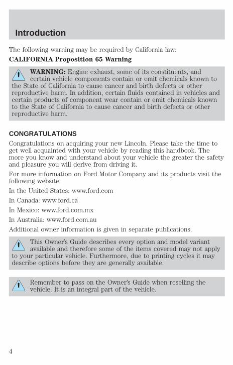
The following warning may be required by California law:
CALIFORNIA Proposition 65 Warning
WARNING: Engine exhaust, some of its constituents, andcertain vehicle components contain or emit chemicals known to
the State of California to cause cancer and birth defects or otherreproductive harm. In addition, certain fluids contained in vehicles andcertain products of component wear contain or emit chemicals knownto the State of California to cause cancer and birth defects or otherreproductive harm.
CONGRATULATIONSCongratulations on acquiring your new Lincoln. Please take the time toget well acquainted with your vehicle by reading this handbook. Themore you know and understand about your vehicle the greater the safetyand pleasure you will derive from driving it.
For more information on Ford Motor Company and its products visit thefollowing website:
In the United States: www.ford.com
In Canada: www.ford.ca
In Mexico: www.ford.com.mx
In Australia: www.ford.com.au
Additional owner information is given in separate publications.
This Owner’s Guide describes every option and model variantavailable and therefore some of the items covered may not apply
to your particular vehicle. Furthermore, due to printing cycles it maydescribe options before they are generally available.
Remember to pass on the Owner’s Guide when reselling thevehicle. It is an integral part of the vehicle.
Introduction
4

Fuel pump shut-off switch In the event of an accident thesafety switch will automatically cut off the fuel supply to the
engine. The switch can also be activated through sudden vibration (e.g.collision when parking). To reset the switch, refer to the Fuel pumpshut-off switch in the Roadside emergencies chapter.
SAFETY AND ENVIRONMENT PROTECTION
Warning symbols in this guideHow can you reduce the risk of personal injury and prevent possibledamage to others, your vehicle and its equipment? In this guide, answersto such questions are contained in comments highlighted by the warningtriangle symbol. These comments should be read and observed.
Warning symbols on your vehicleWhen you see this symbol, it isimperative that you consult therelevant section of this guide beforetouching or attempting adjustmentof any kind.
Protecting the environmentWe must all play our part inprotecting the environment. Correctvehicle usage and the authorizeddisposal of waste cleaning andlubrication materials are significantsteps towards this aim. Information in this respect is highlighted in thisguide with the tree symbol.
BREAKING-IN YOUR VEHICLEThere are no particular guidelines for breaking-in your vehicle. Duringthe first 1 600 km (1 000 miles) of driving, vary speeds frequently. This isrecommended to give the moving parts a chance to break in.
Introduction
5
SPECIAL NOTICES
Emission warrantyThe New Vehicle Limited Warranty includes Bumper-to-BumperCoverage, Safety Restraint Coverage, Corrosion Coverage, and 7.3LPower Stroke Diesel Engine Coverage. In addition, your vehicle is eligiblefor Emissions Defect and Emissions Performance Warranties. For adetailed description of what is covered and what is not covered, refer tothe Warranty Guide that is provided to you along with your Owner’sGuide.
Special instructionsFor your safety, your vehicle is fitted with sophisticated electroniccontrols.
By operating other electronic equipment (e.g. mobile telephonewithout exterior aerial) electromagnetic fields can occur which
can cause malfunctions of the vehicle electronics. Therefore you shouldobserve the instructions of the equipment manufacturers.
Please read the section Air bag in the Seating and safetyrestraints chapter. Failure to follow the specific warnings and
instructions could result in personal injury.
Rear facing child or baby seats should NEVER be used in frontof a passenger side air bag.
Introduction
6

Using your vehicle with a snowplow
Do not use this vehicle for snowplowing.
Using your vehicle as an ambulance
Do not use this vehicle as an ambulance.
Your vehicle is not equipped with the Ford Ambulance PreparationPackage.
Notice to owners of pickup trucks and utility type vehicles
Utility vehicles have a significantly higher rollover rate thanother types of vehicles.
Before you drive your vehicle, please read this Owner’s Guide carefully.Your vehicle is not a passenger car. As with other vehicles of this type,failure to operate this vehicle correctly may result in loss of control or anaccident.
Introduction
7
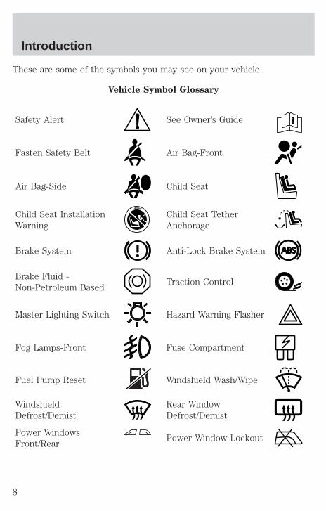
These are some of the symbols you may see on your vehicle.
Vehicle Symbol Glossary
Safety Alert See Owner’s Guide
Fasten Safety Belt Air Bag-Front
Air Bag-Side Child Seat
Child Seat InstallationWarning
Child Seat TetherAnchorage
Brake System Anti-Lock Brake System
Brake Fluid -Non-Petroleum Based
Traction Control
Master Lighting Switch Hazard Warning Flasher
Fog Lamps-Front Fuse Compartment
Fuel Pump Reset Windshield Wash/Wipe
WindshieldDefrost/Demist
Rear WindowDefrost/Demist
Power WindowsFront/Rear
Power Window Lockout
Introduction
8
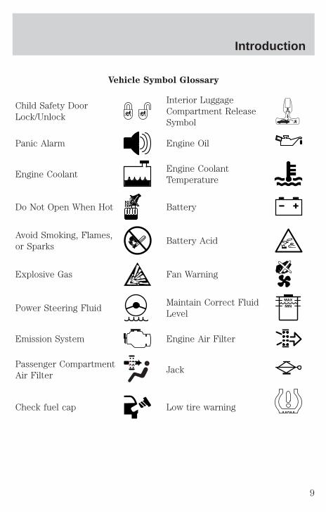
Vehicle Symbol Glossary
Child Safety DoorLock/Unlock
Interior LuggageCompartment ReleaseSymbol
Panic Alarm Engine Oil
Engine CoolantEngine CoolantTemperature
Do Not Open When Hot Battery
Avoid Smoking, Flames,or Sparks
Battery Acid
Explosive Gas Fan Warning
Power Steering FluidMaintain Correct FluidLevel
MAX
MIN
Emission System Engine Air Filter
Passenger CompartmentAir Filter
Jack
Check fuel cap Low tire warning
Introduction
9
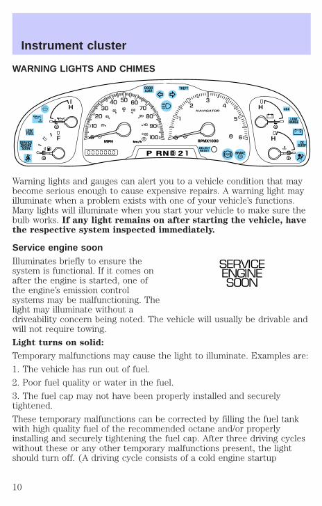
WARNING LIGHTS AND CHIMES
Warning lights and gauges can alert you to a vehicle condition that maybecome serious enough to cause expensive repairs. A warning light mayilluminate when a problem exists with one of your vehicle’s functions.Many lights will illuminate when you start your vehicle to make sure thebulb works. If any light remains on after starting the vehicle, havethe respective system inspected immediately.
Service engine soonIlluminates briefly to ensure thesystem is functional. If it comes onafter the engine is started, one ofthe engine’s emission controlsystems may be malfunctioning. Thelight may illuminate without adriveability concern being noted. The vehicle will usually be drivable andwill not require towing.
Light turns on solid:
Temporary malfunctions may cause the light to illuminate. Examples are:
1. The vehicle has run out of fuel.
2. Poor fuel quality or water in the fuel.
3. The fuel cap may not have been properly installed and securelytightened.
These temporary malfunctions can be corrected by filling the fuel tankwith high quality fuel of the recommended octane and/or properlyinstalling and securely tightening the fuel cap. After three driving cycleswithout these or any other temporary malfunctions present, the lightshould turn off. (A driving cycle consists of a cold engine startup
L
CE
L
H
FMPH RPMX1000
NAVIGATOR
km/hkm/h
DP RN D 2
LOW FUEL
BRAKESELECTRESET
DOORAJAR
4X4
LOWRANGE
CKSUSP
SERVICEENGINESOON
THEFT
20
40
60 80
60
40
20
00H
H
SERVICEENGINESOON
Instrument cluster
10
followed by mixed city/highway driving.) No additional vehicle service isrequired.
If the light remains on, have your vehicle serviced at the first availableopportunity.
Light is blinking:
Engine misfire is occurring which could damage your catalytic converter.You should drive in a moderate fashion (avoid heavy acceleration anddeceleration) and have your vehicle serviced at the first availableopportunity.
Under engine misfire conditions, excessive exhaust temperaturescould damage the catalytic converter, the fuel system, interior
floor coverings or other vehicle components, possibly causing a fire.
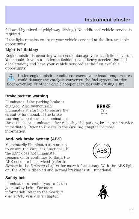
Brake system warningIlluminates if the parking brake isengaged. Also momentarilyilluminates at start up to ensure thecircuit is functional. If the brakewarning lamp does not illuminate atthese times, or illuminates after releasing the parking brake, seek serviceimmediately. Refer to Brakes in the Driving chapter for moreinformation.
Anti-lock brake system (ABS)Momentarily illuminates at start upto ensure the circuit is functional. Ifthe light does not illuminate,remains on or continues to flash, theABS needs to be serviced (refer toBrakes in the Driving chapter for more information). With the ABS lighton, the ABS is disabled and normal braking is still functional.
Safety beltIlluminates to remind you to fastenyour safety belts. For moreinformation, refer to the Seatingand safety restraints chapter.
!BRAKE
ABS
Instrument cluster
11
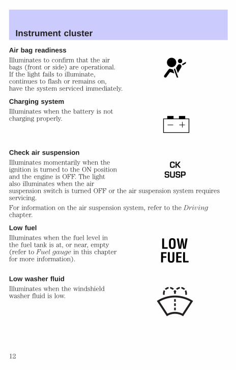
Air bag readinessIlluminates to confirm that the airbags (front or side) are operational.If the light fails to illuminate,continues to flash or remains on,have the system serviced immediately.
Charging systemIlluminates when the battery is notcharging properly.
Check air suspensionIlluminates momentarily when theignition is turned to the ON positionand the engine is OFF. The lightalso illuminates when the airsuspension switch is turned OFF or the air suspension system requiresservicing.
For information on the air suspension system, refer to the Drivingchapter.
Low fuelIlluminates when the fuel level inthe fuel tank is at, or near, empty(refer to Fuel gauge in this chapterfor more information).
Low washer fluidIlluminates when the windshieldwasher fluid is low.
CKSUSP
LOWFUEL
Instrument cluster
12
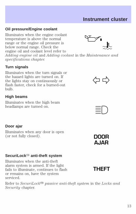
Oil pressure/Engine coolantIlluminates when the engine coolanttemperature is above the normalrange or the engine oil pressure isbelow normal range. Check theengine oil and coolant level refer toAdding engine oil and Adding coolant in the Maintenance andspecifications chapter.
Turn signalsIlluminates when the turn signals orthe hazard lights are turned on. Ifthe lights stay on continuously orflash faster, check for a burned-outbulb.
High beamsIlluminates when the high beamheadlamps are turned on.
Door ajarIlluminates when any door is open(or not fully closed).
SecuriLock Y anti-theft systemIlluminates when the anti-theftalarm system is armed. If the lightfails to illuminate, continues to flashor remains on, have the systemserviced.
Refer to SecuriLocky passive anti-theft system in the Locks andSecurity chapter.
DOORAJAR
THEFT
Instrument cluster
13
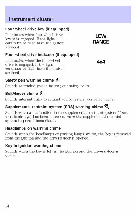
Four wheel drive low (if equipped)Illuminates when four-wheel drivelow is is engaged. If the lightcontinues to flash have the systemserviced.
Four wheel drive indicator (if equipped)Illuminates when the four-wheeldrive is engaged. If the lightcontinues to flash have the systemserviced.
Safety belt warning chimeSounds to remind you to fasten your safety belts.
BeltMinder chimeSounds intermittently to remind you to fasten your safety belts.
Supplemental restraint system (SRS) warning chimeSounds when a malfunction in the supplemental restraint system (frontor side airbags) has been detected. Have the supplemental restraintsystem inspected immediately.
Headlamps on warning chimeSounds when the headlamps or parking lamps are on, the key is removedfrom the ignition and the driver’s door is opened.
Key-in-ignition warning chimeSounds when the key is left in the ignition and the driver’s door isopened.
LOWRANGE
4x4
Instrument cluster
14
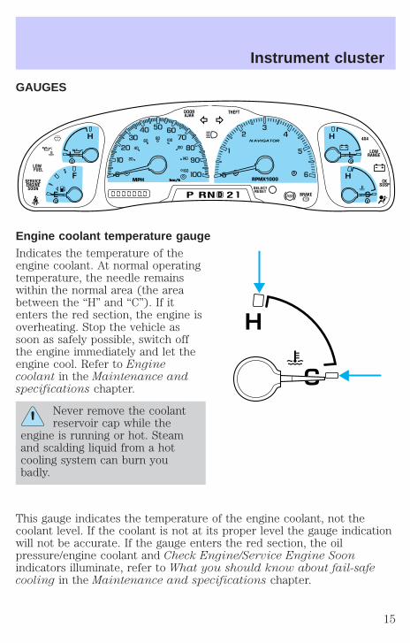
GAUGES
Engine coolant temperature gaugeIndicates the temperature of theengine coolant. At normal operatingtemperature, the needle remainswithin the normal area (the areabetween the “H” and “C”). If itenters the red section, the engine isoverheating. Stop the vehicle assoon as safely possible, switch offthe engine immediately and let theengine cool. Refer to Enginecoolant in the Maintenance andspecifications chapter.
Never remove the coolantreservoir cap while the
engine is running or hot. Steamand scalding liquid from a hotcooling system can burn youbadly.
This gauge indicates the temperature of the engine coolant, not thecoolant level. If the coolant is not at its proper level the gauge indicationwill not be accurate. If the gauge enters the red section, the oilpressure/engine coolant and Check Engine/Service Engine Soonindicators illuminate, refer to What you should know about fail-safecooling in the Maintenance and specifications chapter.
L
CE
L
H
FMPH RPMX1000
NAVIGATOR
km/hkm/h
DP RN D 2
LOW FUEL
BRAKESELECTRESET
DOORAJAR
4X4
LOWRANGE
CKSUSP
SERVICEENGINESOON
THEFT
20
40
60 80
60
40
20
00H
H
C
H
Instrument cluster
15
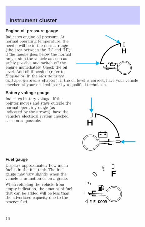
Engine oil pressure gaugeIndicates engine oil pressure. Atnormal operating temperature, theneedle will be in the normal range(the area between the “L” and “H”);if the needle goes below the normalrange, stop the vehicle as soon assafely possible and switch off theengine immediately. Check the oillevel. Add oil if needed (refer toEngine oil in the Maintenanceand specifications chapter). If the oil level is correct, have your vehiclechecked at your dealership or by a qualified technician.
Battery voltage gaugeIndicates battery voltage. If thepointer moves and stays outside thenormal operating range (asindicated by the arrows), have thevehicle’s electrical system checkedas soon as possible.
Fuel gaugeDisplays approximately how muchfuel is in the fuel tank. The fuelgauge may vary slightly when thevehicle is in motion or on a grade.
When refueling the vehicle fromempty indication, the amount of fuelthat can be added will be less thanthe advertised capacity due to thereserve fuel.
L
H
L
H
E
F
FUEL DOOR
Instrument cluster
16
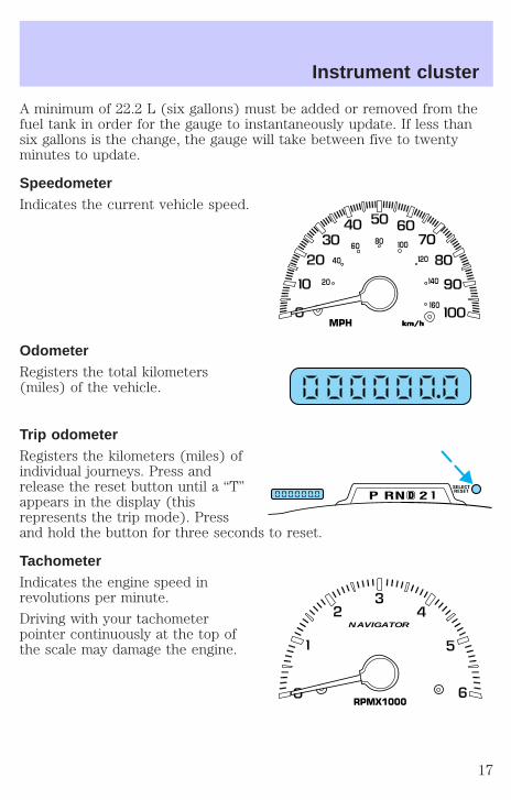
A minimum of 22.2 L (six gallons) must be added or removed from thefuel tank in order for the gauge to instantaneously update. If less thansix gallons is the change, the gauge will take between five to twentyminutes to update.
SpeedometerIndicates the current vehicle speed.
OdometerRegisters the total kilometers(miles) of the vehicle.
Trip odometerRegisters the kilometers (miles) ofindividual journeys. Press andrelease the reset button until a “T”appears in the display (thisrepresents the trip mode). Pressand hold the button for three seconds to reset.
TachometerIndicates the engine speed inrevolutions per minute.
Driving with your tachometerpointer continuously at the top ofthe scale may damage the engine.
MPH km/hkm/h
20
40
60 80
60
40
20
00
DP RN D 2SELECTRESET
RPMX1000
NAVIGATOR
Instrument cluster
17
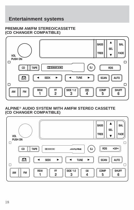
PREMIUM AM/FM STEREO/CASSETTE(CD CHANGER COMPATIBLE)
ALPINET AUDIO SYSTEM WITH AM/FM STEREO CASSETTE(CD CHANGER COMPATIBLE)
SCAN
VOLPUSH ON
REW1
FF2
SIDE 1.23 4
COMP5
SHUFF6
AUTOTUNESEEK
SEL
BAL
FADE
MUTE
FMAM
EJ
BASS
TREB
CD TAPE RDS
SEEKMUTE TUNE SCAN AUTO
VOLPUSH ON
BASS
TREB
BAL
FADE
SEL
CD TAPE RDSEJ
AM FMREW1
FF2
SIDE 1-23 4
COMP5
SHUFF6
DSP
Entertainment systems
18

Your audio system is equipped with selective lighting, a unique lightingstrategy. This lighting feature is operable when the headlamps areilluminated. During the operation of any selected mode, lighting for theindividual function controls will either illuminate or turn off. Thosecontrols which have a function for the specific mode of operationselected will be lit, while the controls which have no function for thatmode will be turned off.
The Alpine Audio System is equipped with a delayed accessory feature.This feature enables the audio playing media to continue playing up to10 minutes after the ignition has been turned off, or until a door isopened.
Volume/power controlPress the control to turn the audiosystem on or off.
Turn the control to raise or lowervolume.
If the volume is set above a certain level and the ignition is turned off,the volume will come back on at a “nominal” listening level when theignition switch is turned back on.
Speed sensitive volume (if equipped)With this feature, radio volume automatically changes slightly withvehicle speed to compensate for road and wind noise.
The recommended level for speed sensitive volume is from level 1through level 3. Level 0 turns the speed sensitive volume off and level 7is the maximum setting.
VOLPUSH ON
VOLPUSH ON
Entertainment systems
19
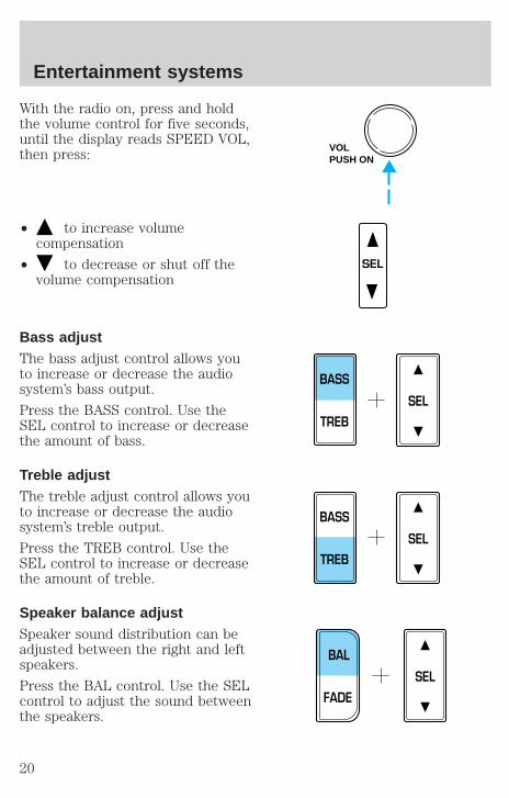
With the radio on, press and holdthe volume control for five seconds,until the display reads SPEED VOL,then press:
• to increase volumecompensation
• to decrease or shut off thevolume compensation
Bass adjustThe bass adjust control allows youto increase or decrease the audiosystem’s bass output.
Press the BASS control. Use theSEL control to increase or decreasethe amount of bass.
Treble adjustThe treble adjust control allows youto increase or decrease the audiosystem’s treble output.
Press the TREB control. Use theSEL control to increase or decreasethe amount of treble.
Speaker balance adjustSpeaker sound distribution can beadjusted between the right and leftspeakers.
Press the BAL control. Use the SELcontrol to adjust the sound betweenthe speakers.
VOLPUSH ON
SEL
SEL
BASS
TREB
SEL
BASS
TREB
SEL
BAL
FADE
Entertainment systems
20
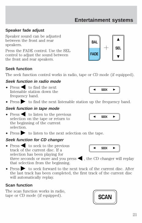
Speaker fade adjustSpeaker sound can be adjustedbetween the front and rearspeakers.
Press the FADE control. Use the SELcontrol to adjust the sound betweenthe front and rear speakers.
Seek functionThe seek function control works in radio, tape or CD mode (if equipped).
Seek function in radio mode• Press to find the next
listenable station down thefrequency band.
• Press to find the next listenable station up the frequency band.
Seek function in tape mode• Press to listen to the previous
selection on the tape or return tothe beginning of the currentselection.
• Press to listen to the next selection on the tape.
Seek function for CD changer• Press to seek to the previous
track of the current disc. If aselection has been playing forthree seconds or more and you press , the CD changer will replaythat selection from the beginning.
• Press to seek forward to the next track of the current disc. Afterthe last track has been completed, the first track of the current discwill automatically replay.
Scan functionThe scan function works in radio,tape or CD mode (if equipped).
SEL
BAL
FADE
SEEK
SEEK
SEEK
SCAN
Entertainment systems
21
Scan function in radio modePress the SCAN control to activate scan mode and to hear a briefsampling of all listenable stations on the frequency band.
Press the SCAN control again to disengage scan mode.
Scan function in tape modePress the SCAN control to hear a short sampling of all selections on thetape. The tape will scan in a forward direction. At the end of the tape’sfirst side, direction automatically reverses to the opposite side of thetape.
To stop on a particular selection, press the SCAN control again.
Scan function in CD modePress the SCAN control to hear a short sampling of all selections on theCD. The CD will scan in a forward direction, wrapping back to the firsttrack at the end of the CD.
To stop on a particular selection, press the control again.
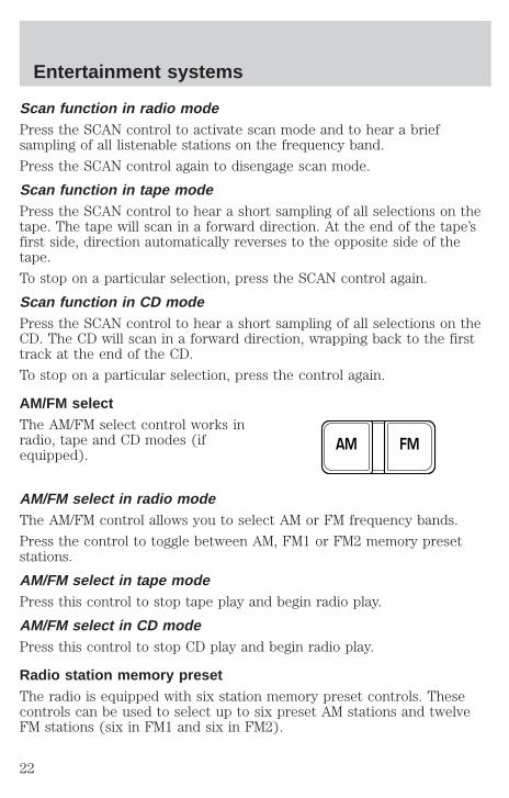
AM/FM selectThe AM/FM select control works inradio, tape and CD modes (ifequipped).
AM/FM select in radio modeThe AM/FM control allows you to select AM or FM frequency bands.
Press the control to toggle between AM, FM1 or FM2 memory presetstations.
AM/FM select in tape modePress this control to stop tape play and begin radio play.
AM/FM select in CD modePress this control to stop CD play and begin radio play.
Radio station memory presetThe radio is equipped with six station memory preset controls. Thesecontrols can be used to select up to six preset AM stations and twelveFM stations (six in FM1 and six in FM2).
FMAM
Entertainment systems
22
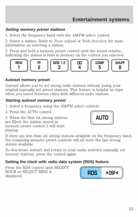
Setting memory preset stations1. Select the frequency band with the AM/FM select control.
2. Select a station. Refer to Tune adjust or Seek function for moreinformation on selecting a station.
3. Press and hold a memory preset control until the sound returns,indicating the station is held in memory on the control you selected.
Autoset memory presetAutoset allows you to set strong radio stations without losing youroriginal manually set preset stations. This feature is helpful on tripswhen you travel between cities with different radio stations.
Starting autoset memory preset1. Select a frequency using the AM/FM select controls.
2. Press the AUTO control.
3. When the first six strong stationsare filled, the station stored inmemory preset control 1 will startplaying.
If there are less than six strong stations available on the frequency band,the remaining memory preset controls will all store the last strongstation available.
To deactivate autoset and return to your audio system’s manually setmemory stations, press the control again.
Setting the clock with radio data system (RDS) featurePress the RDS control until SELECTHOUR or SELECT MINS isdisplayed.
REW1
FF2
SIDE 1.23 4
COMP5
SHUFF6
AUTO
RDS DSP
Entertainment systems
23

Use the SEL control to manually setthe time.
• Press to increasehours/minutes.
• Press to decreasehours/minutes.
Tune adjustThe tune control works in radio or CD mode (if equipped).
Tune adjust in radio mode• Press to move to the next
frequency down the band(whether or not a listenablestation is located there). Hold the control to move through thefrequencies quickly.
• Press to move to the next frequency up the band (whether or nota listenable station is located there). Hold for quick movement.
Tune adjust for CD changer• Press to select the previous
disc in the CD changer. (Play willbegin on the first track of thedisc unless the CD changer is in shuffle mode.) Refer to Shufflefeature for more information. Hold the control to continue reversingthrough the discs.
• Press to select the next disc in the CD changer. Hold the controlto fast-forward through the remaining discs.
Tape/CD select• To begin tape play (with a tape
loaded into the audio system)while in the radio or CD mode,press the TAPE control. Press thebutton during rewind or fast forward to stop the rewind or fastforward function.
SEL
TUNE
TUNE
CD TAPE
Entertainment systems
24

• To begin CD play (if equippedwith CD changer), ensure thatthe CDs are loaded. Press the CDcontrol. The first track of the discwill begin playing. After that, CD play will begin where it stopped last.
Do not insert any promotional (odd shaped or sized) discs, or discswith removable labels into the CD player as jamming may occur.
RewindThe rewind control works in tapeand CD modes.
• In tape mode, radio play willcontinue until rewind is stopped(with the TAPE control) or the beginning of the tape is reached.
• In CD mode, pressing the REW control for less than three secondsresults in slow rewind. Pressing the control for more than threeseconds results in fast rewind.
Fast forwardThe fast forward control works intape and CD modes (if equipped).
• In the tape mode, tape directionwill automatically reverse whenthe end of the tape is reached.
• In CD mode, pressing the control for less than three seconds results inslow forward action. Pressing the control for more than three secondsresults in fast forward action.
Tape direction selectPress SIDE 1–2 to play the alternateside of a tape.
Eject functionPress the control to stop and eject atape.
CD TAPE
REW1
FF2
SIDE 1-23
EJ
Entertainment systems
25
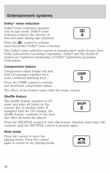
Dolby T noise reductionDolbyt noise reduction operatesonly in tape mode. Dolbyt noisereduction reduces the amount ofhiss and static during tape playback.
Press the control to activate(and deactivate) Dolbyt noise reduction.
The Dolbyt noise reduction system is manufactured under license fromDolby Laboratories Licensing Corporation. Dolbyt and the double-Dsymbol are registered trademarks of Dolbyt Labratories LicensingCorporation.
Compression featureCompression adjust brings soft andloud CD passages together for amore consistent listening level.
Press the COMP control to activateand deactivate compression adjust.
The effect of the feature varies with the music content.
Shuffle featureThe shuffle feature operates in CDmode and plays all tracks on thecurrent disc in random order. Ifequipped with the CD changer, theshuffle feature continues to the nextdisc after all tracks are played.
Press the SHUFFLE control to start this feature. Random order play willcontinue until the SHUFFLE control is pressed again.
Mute modePress the control to mute theplaying media. Press the controlagain to return to the playing media.
4
COMP5
SHUFF6
MUTE
Entertainment systems
26
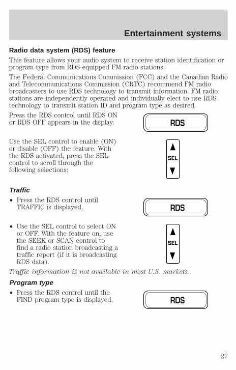
Radio data system (RDS) featureThis feature allows your audio system to receive station identification orprogram type from RDS-equipped FM radio stations.
The Federal Communications Commission (FCC) and the Canadian Radioand Telecommunications Commission (CRTC) recommend FM radiobroadcasters to use RDS technology to transmit information. FM radiostations are independently operated and individually elect to use RDStechnology to transmit station ID and program type as desired.
Press the RDS control until RDS ONor RDS OFF appears in the display.
Use the SEL control to enable (ON)or disable (OFF) the feature. Withthe RDS activated, press the SELcontrol to scroll through thefollowing selections:
Traffic• Press the RDS control until
TRAFFIC is displayed.
• Use the SEL control to select ONor OFF. With the feature on, usethe SEEK or SCAN control tofind a radio station broadcasting atraffic report (if it is broadcastingRDS data).
Traffic information is not available in most U.S. markets.
Program type• Press the RDS control until the
FIND program type is displayed.
RDS
SEL
RDS
SEL
RDS
Entertainment systems
27
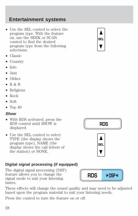
• Use the SEL control to select theprogram type. With the featureon, use the SEEK or SCANcontrol to find the desiredprogram type from the followingselections:
• Classic
• Country
• Info
• Jazz
• Oldies
• R & B
• Religious
• Rock
• Soft
• Top 40
Show• With RDS activated, press the
RDS control until SHOW isdisplayed.
• Use the SEL control to selectTYPE (the display shows theprogram type), NAME (thedisplay shows the call letters ofthe station) or NONE.
Digital signal processing (if equipped)The digital signal processing (DSP)feature allows you to change thesignal mode to suit your listeningtastes.
These effects will change the sound quality and may need to be adjustedbased upon the program material to suit your listening needs.
Press the control to turn the feature on or off.
SEL
RDS
SEL
RDS DSP
Entertainment systems
28

Use the SEL control to select thedesired signal mode (the selectedmode will appear in the display).The following signal modes can beselected:
• JAZZ CLUB—jazz club withclearly reflected sounds.
• HALL—rectangular concert hall capacity of about 2 000
• CHURCH—church with a high vault.
• STADIUM—outdoor stadium with a capacity of about 30 000.
• NEWS—“voice-only” type of sound with a limited audio band.
Press the DSP control until one ofthe following appears:
• ALL SEATS
• DRIVER SEAT
• REAR SEATS
Use the SELECT control to changethe equalization to the desiredmode.
REAR SEAT CONTROLS (IF EQUIPPED)The Personal Audio System, allowsfront and middle seat passengers tolisten to different media sources(radio, cassette or CD)simultaneously. However, the frontand middle-seat passengers cannotlisten to two different radio stationsat the same time.
SEL
RDS DSP
SEL
- VOLUME + MODE
SEEK MEMORY
Entertainment systems
29
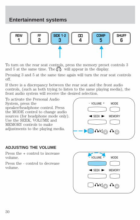
To turn on the rear seat controls, press the memory preset controls 3and 5 at the same time. The will appear in the display.
Pressing 3 and 5 at the same time again will turn the rear seat controlsoff.
If there is a discrepancy between the rear seat and the front audiocontrols, (such as both trying to listen to the same playing media), thefront audio system will receive the desired selection.
To activate the Personal AudioSystem, press thespeaker/headphone control. Pressthe MODE control to change audiosources (for headphone mode only).Use the SEEK, VOLUME andMEMORY controls to makeadjustments to the playing media.
ADJUSTING THE VOLUMEPress the + control to increasevolume.
Press the - control to decreasevolume.
REW1
FF2
SIDE 1.23 4
COMP5
SHUFF6
- VOLUME + MODE
SEEK MEMORY
- VOLUME + MODE
SEEK MEMORY
Entertainment systems
30
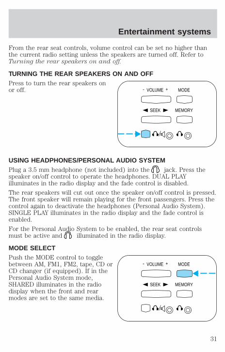
From the rear seat controls, volume control can be set no higher thanthe current radio setting unless the speakers are turned off. Refer toTurning the rear speakers on and off.
TURNING THE REAR SPEAKERS ON AND OFFPress to turn the rear speakers onor off.
USING HEADPHONES/PERSONAL AUDIO SYSTEMPlug a 3.5 mm headphone (not included) into the jack. Press thespeaker on/off control to operate the headphones. DUAL PLAYilluminates in the radio display and the fade control is disabled.
The rear speakers will cut out once the speaker on/off control is pressed.The front speaker will remain playing for the front passengers. Press thecontrol again to deactivate the headphones (Personal Audio System).SINGLE PLAY illuminates in the radio display and the fade control isenabled.
For the Personal Audio System to be enabled, the rear seat controlsmust be active and illuminated in the radio display.
MODE SELECTPush the MODE control to togglebetween AM, FM1, FM2, tape, CD orCD changer (if equipped). If in thePersonal Audio System mode,SHARED illuminates in the radiodisplay when the front and rearmodes are set to the same media.
- VOLUME + MODE
SEEK MEMORY
- VOLUME + MODE
SEEK MEMORY
Entertainment systems
31

MEMORY PRESET CONTROLPush the MEMORY controlsuccessively to allow rear seatpassengers to scroll through the 6memory presets in AM, FM1 orFM2.
Push the MEMORY control in CDchanger mode (if equipped) toadvance to the next disc.
SEEK FUNCTION• In radio mode, press to find
the next listenable station downthe frequency band.
• In radio mode, press to findthe next listenable station up thefrequency band.
• In tape mode, use the SEEKfunction to access the next orprevious selection.
• In CD mode (if equipped), usethe SEEK function to access the next or previous selection.
CD CHANGER (IF EQUIPPED)Your CD changer is located in the center console.
Slide the door to access the CDchanger magazine.
- VOLUME + MODE
SEEK MEMORY
- VOLUME + MODE
SEEK MEMORY
Entertainment systems
32
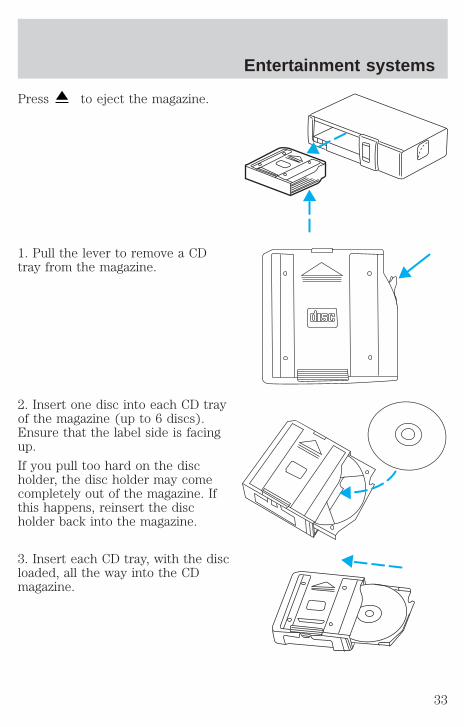
Press to eject the magazine.
1. Pull the lever to remove a CDtray from the magazine.
2. Insert one disc into each CD trayof the magazine (up to 6 discs).Ensure that the label side is facingup.
If you pull too hard on the discholder, the disc holder may comecompletely out of the magazine. Ifthis happens, reinsert the discholder back into the magazine.
3. Insert each CD tray, with the discloaded, all the way into the CDmagazine.
Entertainment systems
33

4. Insert the CD magazine into thechanger.
5. Slide the door to the left to close.
Use only compact discs containingthis mark.
The magazine does not need to be full for the changer to operate.
Radio power must be turned on to play the CDs in the changer. Themagazine may be stored in the glove compartment when not being used.
The CD magazine may be inserted or ejected with the radio power off.
Keep the CD changer door closed. Coins and foreign objects will damagethe CD player and void your audio system warranty.
Do not insert any promotional (odd shaped or sized) discs, ordiscs with removable labels into the CD player as jamming mayoccur.
TROUBLESHOOTING THE CD CHANGER (IF EQUIPPED)
The laser beam used in the compact disc player is harmful to theeyes. Do not attempt to disassemble the case.
If sound skips:
• You may be traveling on a rough road, playing badly scratched discs orthe disc may be dirty. Skipping will not scratch the discs or damagethe player.
Entertainment systems
34
If your changer does not work, it may be that:
• A disc is already loaded where you want to insert a disc.
• The disc is inserted with the label surface downward.
• The disc is dusty or defective.
• A disc with format and dimensions not within industry standards isinserted.
CLEANING COMPACT DISCSInspect all discs for contamination before playing. If necessary, cleandiscs only with an approved CD cleaner and wipe from the center out tothe edge. Do not use circular motion.
CD AND CD CHANGER CARE• Handle discs by their edges only. Never touch the playing surface.
• Do not expose discs to direct sunlight or heat sources for extendedperiods of time.
• Do not insert more than one disc into each slot of the CD changermagazine.
Do not insert any promotional (odd shaped or sized) discs, ordiscs with removable labels into the CD player as jamming mayoccur.
CLEANING CASSETTE PLAYER (IF EQUIPPED)Clean the tape player head with a cassette cleaning cartridge after 10 to12 hours of play in order to maintain the best sound and operation.
CASSETTE AND CASSETTE PLAYER CARE• Use only cassettes that are 90 minutes long or less.
• Do not expose tapes to direct sunlight, high humidity, extreme heat orextreme cold. Allow tapes that may have been exposed to extremetemperatures to reach a moderate temperature before playing.
• Tighten very loose tapes by inserting a finger or pencil into the holeand turning the hub.
• Remove loose labels before inserting tapes.
• Do not leave tapes in the cassette player for a long time when notbeing played.
Entertainment systems
35
RADIO FREQUENCY INFORMATIONThe Federal Communications Commission (FCC) and the Canadian Radioand Telecommunications Commission(CRTC) establish the frequenciesAM and FM stations may use for their broadcasts. Allowable frequenciesare:
AM 530, 540–1600, 1610 kHz
FM 87.7, 87.9–107.7, 107.9 MHz
Not all frequencies are used in a given area.
RADIO RECEPTION FACTORSThree factors can affect radio reception:
• Distance/strength. The further an FM signal travels, the weaker it is.The listenable range of the average FM station is approximately 40 km(24 miles). This range can be affected by “signal modulation.” Signalmodulation is a process radio stations use to increase theirstrength/volume relative to other stations.
• Terrain. Hills, mountains and tall buildings between your vehicle’santenna and the radio station signal can cause FM reception problems.Static can be caused on AM stations by power lines, electric fences,traffic lights and thunderstorms. Moving away from an interferingstructure (out of its “shadow”) returns your reception to normal.
• Station overload. Weak signals are sometimes captured by strongersignals when you pass a broadcast tower. A stronger signal maytemporarily overtake a weaker signal and play while the weak stationfrequency is displayed.
The audio system automatically switches to single channel reception if itwill improve the reception of a station normally received in stereo.
AUDIO SYSTEM WARRANTIES AND SERVICERefer to the Warranty Guide for audio system warranty information.
If service is necessary, see your dealer or a qualified technician.
Entertainment systems
36
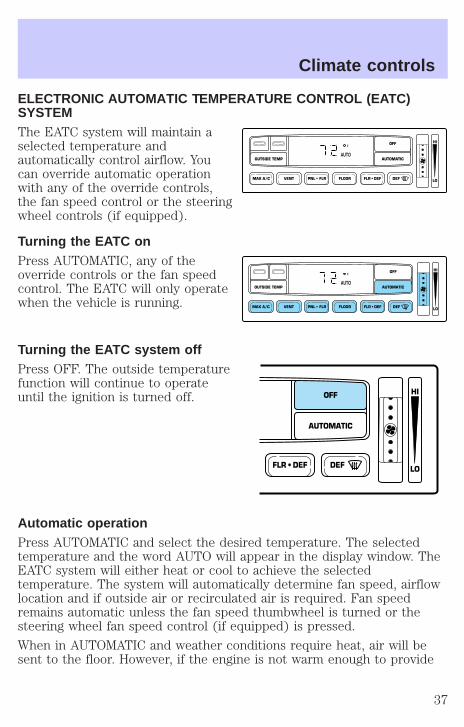
ELECTRONIC AUTOMATIC TEMPERATURE CONTROL (EATC)SYSTEMThe EATC system will maintain aselected temperature andautomatically control airflow. Youcan override automatic operationwith any of the override controls,the fan speed control or the steeringwheel controls (if equipped).
Turning the EATC onPress AUTOMATIC, any of theoverride controls or the fan speedcontrol. The EATC will only operatewhen the vehicle is running.
Turning the EATC system offPress OFF. The outside temperaturefunction will continue to operateuntil the ignition is turned off.
Automatic operationPress AUTOMATIC and select the desired temperature. The selectedtemperature and the word AUTO will appear in the display window. TheEATC system will either heat or cool to achieve the selectedtemperature. The system will automatically determine fan speed, airflowlocation and if outside air or recirculated air is required. Fan speedremains automatic unless the fan speed thumbwheel is turned or thesteering wheel fan speed control (if equipped) is pressed.
When in AUTOMATIC and weather conditions require heat, air will besent to the floor. However, if the engine is not warm enough to provide
VENT PNL • FLR FLOOR FLR • DEF DEF
HI
LOMAX A/C
OUTSIDE TEMP AUTOMATIC
OFFF
AUTO
VENT PNL • FLR FLOOR FLR • DEF DEF
HI
LOMAX A/C
OUTSIDE TEMP AUTOMATIC
OFFF
AUTO
FLR • DEF DEF
HI
LO
AUTOMATIC
OFF
Climate controls
37

heat, the fan will be at a low speed and the air will be directed to thewindshield. In approximately 31⁄2 minutes or less, the fan speed will startto increase and the airflow location will change to the floor area.
If unusual conditions exist (i.e.-window fogging, etc.), the manualoverride controls allow you to select airflow locations and the fan controlallows you to adjust fan speed as necessary.
Temperature selectionThe display window indicates theselected temperature, function(AUTO or one of the overridecontrols) and manual control of fanspeed ( ) if automatic fan speed is not desired.
To control the temperature, selectany temperature between 18°C(65°F) and 29°C (85°F) by pressingthe blue (cooler) or red (warmer)buttons.
For continuous maximum cooling, push the blue button until 16°C(60°F) is shown in the display window. The EATC will continuemaximum cooling (disregarding the displayed temperature) until awarmer temperature is selected by pressing the red control.
For continuous maximum heating, push the red button until 32°C (90°F)is shown in the display window. The EATC will continue maximumheating (disregarding the displayed temperature) until a coolertemperature is selected by pressing the blue control.
˚FAUTO
VENT PNL • FLRMAX A/C
OUTSIDE TEMP
Climate controls
38

Temperature conversionPress MAX A/C and DEF atthe same time (for one second) toswitch between Fahrenheit andCelsius.
The English/Metric (E/M) control onthe trip computer and message center (if equipped) will not changetemperature display.
Fan speed ( )When AUTOMATIC is pressed, fanspeed is adjusted automatically forexisting conditions. You can overridefan speed at any time. To controlfan speed manually, use thethumbwheel to cancel automatic fanspeed operation. Rotate the thumbwheel or press the steering wheelcontrols (if equipped) up for higher fan speed or down for lower fanspeed.
The display will show toindicate manual fan operation.
To return to automatic fan operation, press AUTOMATIC.
Manual override controlsThe manual override controls allowyou to determine where airflow isdirected. To return to full automaticcontrol, press AUTOMATIC.
The air conditioning compressor can operate in all modes except FLOORand VENT. It will also operate only when required when AUTOMATIChas been selected. However, the air conditioning will only function if theoutside temperature is about 6°C (43°F) or higher.
Since the air conditioner removes considerable moisture from the airduring operation, it is normal if clear water drips on the ground underthe air conditioner drain while the system is working and even after youhave stopped the vehicle.
VENT PNL • FLR FLOOR FLR • DEF DEF
HI
LOMAX A/C
OUTSIDE TEMP AUTOMATIC
OFF
AUTO
˚FAUTO
VENT PNL • FLR FLOOR FLR • DEF DEF
HI
LOMAX A/C
OUTSIDE TEMP AUTOMATIC
OFFF
AUTO
Climate controls
39

• MAX A/C-Uses recirculated air to cool the vehicle. The temperaturewill display 16°C (60°F). To exit, press AUTOMATIC or any otheroverride controls. MAX A/C is louder than normal A/C but moreeconomical and will cool the inside of the vehicle faster. Airflow isfrom the instrument panel registers. This mode can also be used toprevent undesirable odors from entering the vehicle.
• VENT-Distributes outside air through the instrument panel registers.However, the air cannot be cooled below the outside temperaturebecause the air conditioning does not operate in this mode.
• PNL•FLR-Distributes outside air through the instrument panelregisters and the floor ducts. Heating and air conditioning capabilitiesare provided in this mode. The air will be heated or cooled based onthe temperature selection. For added customer comfort, the airdistributed through the floor ducts will be slightly warmer than the airsent to the instrument panel registers.
• FLOOR-Distributes outside air through the floor ducts. However, theair cannot be cooled below the outside temperature because the airconditioning does not operate in this mode.
• FLR•DEF-Distributes outside air through the windshield defrosterducts and the floor ducts. Heating and air conditioning capabilities areprovided in this mode. The air will be heated or cooled based on thetemperature selection. For added customer comfort, the airdistributed through the floor ducts will be slightly warmer than the airsent to the windshield defroster ducts. If the temperature is about 6°C(43°F) or higher, the air conditioner will automatically dehumidify theair to reduce fogging.
• DEF -Distributes outside air through the windshield defrosterducts. It can be used to clear ice or fog from the windshield. If theoutside air temperature is about 6°C (43°F) or higher, the airconditioner will automatically dehumidify the air to reduce fogging.
• OFF-Outside air is shut out and the fan will not operate. For shortperiods of time only, use this mode to reduce undesirable odors fromentering the vehicle.
Climate controls
40
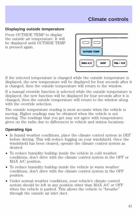
Displaying outside temperaturePress OUTSIDE TEMP to displaythe outside air temperature. It willbe displayed until OUTSIDE TEMPis pressed again.
If the selected temperature is changed while the outside temperature isdisplayed, the new temperature will be displayed for four seconds after itis changed, then the outside temperature will return to the window.
If a manual override function is selected while the outside temperature isdisplayed, the new function will be displayed for four seconds after it ischanged, then the outside temperature will return to the window alongwith the override selection.
The outside temperature reading is most accurate when the vehicle ismoving. Higher readings may be obtained when the vehicle is notmoving. The readings that you get may not agree with temperaturesgiven on the radio due to differences in vehicle and station locations.
Operating tips• In humid weather conditions, place the climate control system in DEF
before driving. This will reduce fogging on your windshield. Once thewindshield has been cleared, operate the climate control system asdesired.
• To reduce humidity buildup inside the vehicle in cold weatherconditions, don’t drive with the climate control system in the OFF orMAX A/C position.
• To reduce humidity buildup inside the vehicle in warm weatherconditions, don’t drive with the climate control system in the OFFposition.
• Under normal weather conditions, your vehicle’s climate controlsystem should be left in any position other than MAX A/C or OFFwhen the vehicle is parked. This allows the vehicle to “breathe”through the outside air inlet duct.
VENT PNL • FLRMAX A/C
OUTSIDE TEMP
Climate controls
41

• Under snowy or dirty weather conditions, your vehicle’s climatecontrol system should be left in the OFF position when the vehicle isparked. This allows the climate control system to be free fromcontamination of outside pollutants.
• If your vehicle has been parked with the windows closed during warmweather conditions, the air conditioner will perform more efficiently incooling the vehicle if driven for two or three minutes with thewindows open. This will force most of the hot, stale air out of thevehicle. Once the vehicle has been “aired out”, operate the climatecontrol system as desired.
• Don’t put objects under the front seat that will interfere with theairflow to the rear seats.
• Remove any snow, ice or leaves from the air intake area at the base ofthe windshield.
• Do not place objects over the defroster outlets. These objects canblock airflow and reduce your ability to see through your windshield.Avoid placing small objects on top of the instrument panel. Theseobjects may fall down into the defroster outlets and block airflow, inaddition to damaging the climate control system.
To aid in side window defogging/demisting in cold weather conditions:
1. Select PNL • FLR
2. Set the temperature control to full heat
3. Set the fan speed control to HI
4. Direct the outer panel vents towards the side windows.
To increase airflow to the outer panel vents, close the central panelvents.
Do not place objects on top of the instrument panel, as theseobjects may become projectiles in a collision or sudden stop.
REAR CONSOLE CLIMATE CONTROLS (IF EQUIPPED)Depending on the equipment package of your vehicle, the rear consolemay be equipped with audio/climate controls.
The instrument panel climate controls must be on in order for the rearconsole climate controls to work.
Climate controls
42
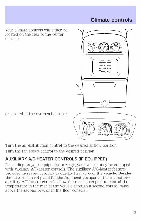
Your climate controls will either belocated on the rear of the centerconsole,
or located in the overhead console.
Turn the air distribution control to the desired airflow position.
Turn the fan speed control to the desired position.
AUXILIARY A/C-HEATER CONTROLS (IF EQUIPPED)Depending on your equipment package, your vehicle may be equippedwith auxiliary A/C-heater controls. The auxiliary A/C-heater featureprovides increased capacity to quickly heat or cool the vehicle. Besidesthe driver’s control panel for the front seat occupants, the second rowauxiliary A/C-heater controls allow the rear passengers to control thetemperature in the rear of the vehicle through a second control panelabove the second row, or in the floor console.
MODE- VOLUME +
SEEK MEMORY
OFF
COOL WARM PANEL FLOOR
LO
HI
OFF LO
HI
COOL WARM PANEL FLOOR
Climate controls
43
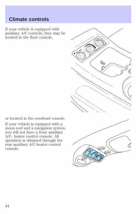
If your vehicle is equipped withauxiliary A/C controls, they may belocated in the floor console,
or located in the overhead console.
If your vehicle is equipped with amoon roof and a navigation system,you will not have a front auxiliaryA/C- heater control console. Alloperation is obtained through therear auxiliary A/C-heater controlconsole.
HIOFFREAR
WARM
COOL
PANEL
FLOOR
Climate controls
44
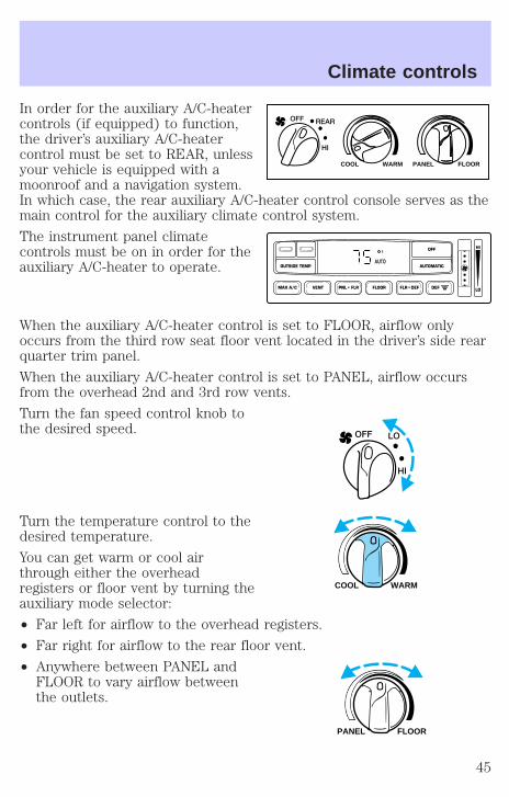
In order for the auxiliary A/C-heatercontrols (if equipped) to function,the driver’s auxiliary A/C-heatercontrol must be set to REAR, unlessyour vehicle is equipped with amoonroof and a navigation system.In which case, the rear auxiliary A/C-heater control console serves as themain control for the auxiliary climate control system.
The instrument panel climatecontrols must be on in order for theauxiliary A/C-heater to operate.
When the auxiliary A/C-heater control is set to FLOOR, airflow onlyoccurs from the third row seat floor vent located in the driver’s side rearquarter trim panel.
When the auxiliary A/C-heater control is set to PANEL, airflow occursfrom the overhead 2nd and 3rd row vents.
Turn the fan speed control knob tothe desired speed.
Turn the temperature control to thedesired temperature.
You can get warm or cool airthrough either the overheadregisters or floor vent by turning theauxiliary mode selector:
• Far left for airflow to the overhead registers.
• Far right for airflow to the rear floor vent.
• Anywhere between PANEL andFLOOR to vary airflow betweenthe outlets.
WARM PANEL FLOORCOOL
REAROFF
HI
VENT PNL • FLR FLOOR FLR • DEF DEF
HI
LOMAX A/C
OUTSIDE TEMP AUTOMATIC
OFFF
AUTO
LOOFF
HI
WARMCOOL
FLOORPANEL
Climate controls
45
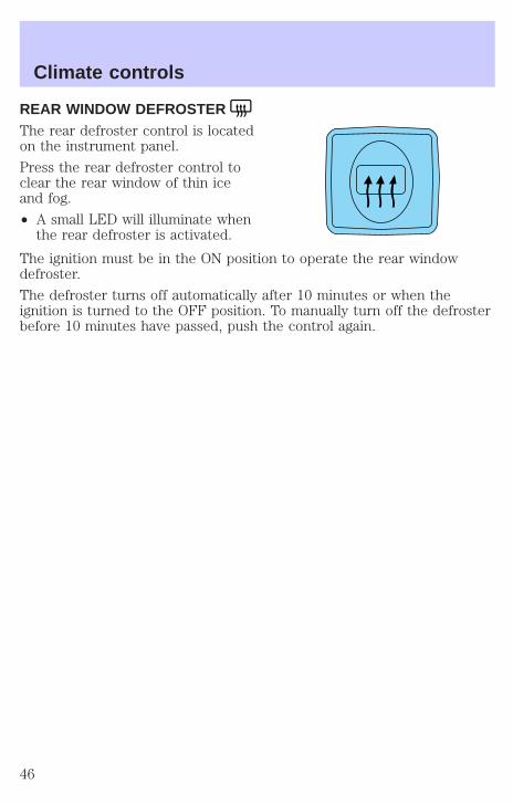
REAR WINDOW DEFROSTERThe rear defroster control is locatedon the instrument panel.
Press the rear defroster control toclear the rear window of thin iceand fog.
• A small LED will illuminate whenthe rear defroster is activated.
The ignition must be in the ON position to operate the rear windowdefroster.
The defroster turns off automatically after 10 minutes or when theignition is turned to the OFF position. To manually turn off the defrosterbefore 10 minutes have passed, push the control again.
Climate controls
46
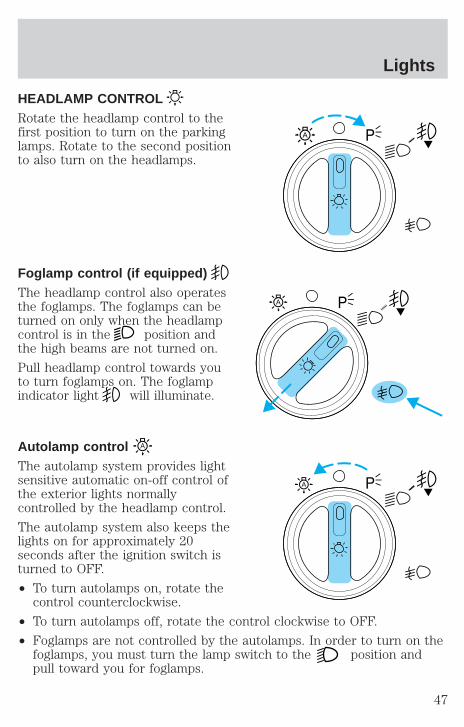
HEADLAMP CONTROLRotate the headlamp control to thefirst position to turn on the parkinglamps. Rotate to the second positionto also turn on the headlamps.
Foglamp control (if equipped)The headlamp control also operatesthe foglamps. The foglamps can beturned on only when the headlampcontrol is in the position andthe high beams are not turned on.
Pull headlamp control towards youto turn foglamps on. The foglampindicator light will illuminate.
Autolamp controlThe autolamp system provides lightsensitive automatic on-off control ofthe exterior lights normallycontrolled by the headlamp control.
The autolamp system also keeps thelights on for approximately 20seconds after the ignition switch isturned to OFF.
• To turn autolamps on, rotate thecontrol counterclockwise.
• To turn autolamps off, rotate the control clockwise to OFF.
• Foglamps are not controlled by the autolamps. In order to turn on thefoglamps, you must turn the lamp switch to the position andpull toward you for foglamps.
A
A
A
Lights
47
Daytime running lamps (DRL) (if equipped)Turns the headlamps on with a reduced output. To activate:
• the ignition must be in the ON position and
• the headlamp control is in the OFF or Parking lamps position.
Always remember to turn on your headlamps at dusk or duringinclement weather. The Daytime Running Lamp (DRL) system
does not activate with your tail lamps and generally may not provideadequate lighting during these conditions. Failure to activate yourheadlamps under these conditions may result in a collision.
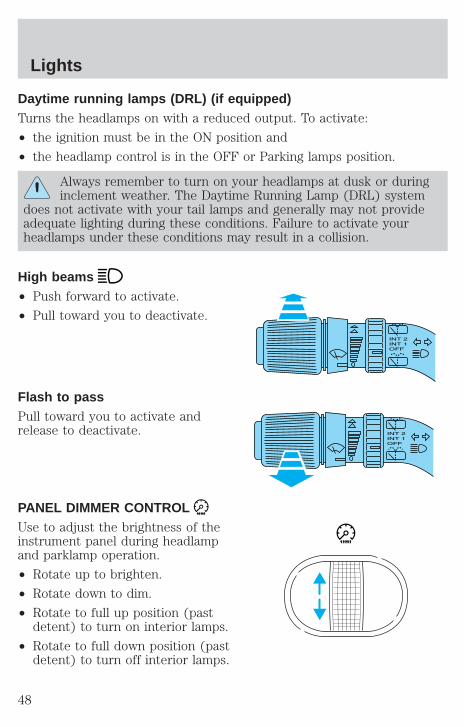
High beams• Push forward to activate.
• Pull toward you to deactivate.
Flash to passPull toward you to activate andrelease to deactivate.
PANEL DIMMER CONTROLUse to adjust the brightness of theinstrument panel during headlampand parklamp operation.
• Rotate up to brighten.
• Rotate down to dim.
• Rotate to full up position (pastdetent) to turn on interior lamps.
• Rotate to full down position (pastdetent) to turn off interior lamps.
Lights
48
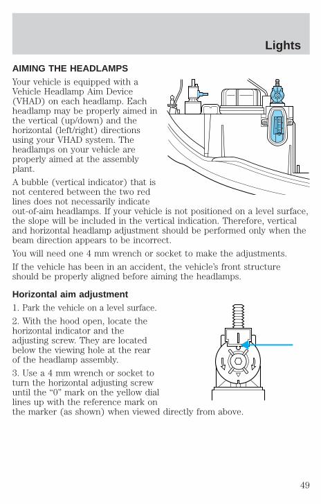
AIMING THE HEADLAMPSYour vehicle is equipped with aVehicle Headlamp Aim Device(VHAD) on each headlamp. Eachheadlamp may be properly aimed inthe vertical (up/down) and thehorizontal (left/right) directionsusing your VHAD system. Theheadlamps on your vehicle areproperly aimed at the assemblyplant.
A bubble (vertical indicator) that isnot centered between the two redlines does not necessarily indicateout-of-aim headlamps. If your vehicle is not positioned on a level surface,the slope will be included in the vertical indication. Therefore, verticaland horizontal headlamp adjustment should be performed only when thebeam direction appears to be incorrect.
You will need one 4 mm wrench or socket to make the adjustments.
If the vehicle has been in an accident, the vehicle’s front structureshould be properly aligned before aiming the headlamps.
Horizontal aim adjustment1. Park the vehicle on a level surface.
2. With the hood open, locate thehorizontal indicator and theadjusting screw. They are locatedbelow the viewing hole at the rearof the headlamp assembly.
3. Use a 4 mm wrench or socket toturn the horizontal adjusting screwuntil the “0” mark on the yellow diallines up with the reference mark onthe marker (as shown) when viewed directly from above.
U
D
Lights
49
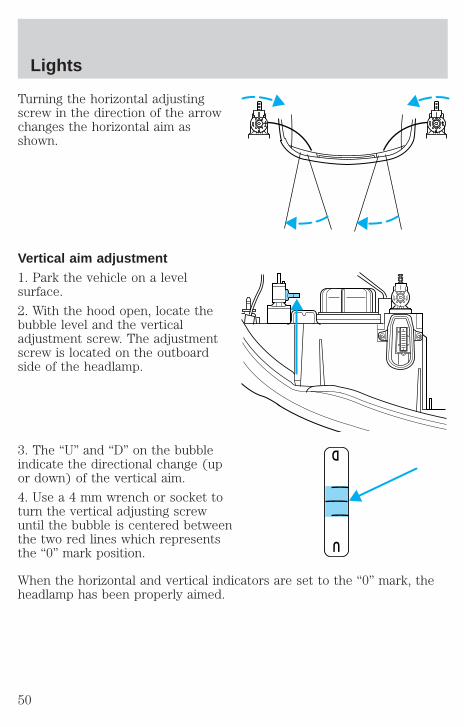
Turning the horizontal adjustingscrew in the direction of the arrowchanges the horizontal aim asshown.
Vertical aim adjustment1. Park the vehicle on a levelsurface.
2. With the hood open, locate thebubble level and the verticaladjustment screw. The adjustmentscrew is located on the outboardside of the headlamp.
3. The “U” and “D” on the bubbleindicate the directional change (upor down) of the vertical aim.
4. Use a 4 mm wrench or socket toturn the vertical adjusting screwuntil the bubble is centered betweenthe two red lines which representsthe “0” mark position.
When the horizontal and vertical indicators are set to the “0” mark, theheadlamp has been properly aimed.
U
D
D
U
Lights
50

TURN SIGNAL CONTROL• Push down to activate the left
turn signal.
• Push up to activate the right turnsignal.
INTERIOR LAMPS
Map lampsTo turn on the map lamps, press thecontrol next to each lamp.
Rear dome lampThe dome lamp lights when:
• any door is opened.
• the instrument panel dimmerswitch is held up until thecourtesy lamps come on.
• any of the remote entry controlsare pressed and the ignition isOFF.
With the ignition key in the ACC or ON position, the rear dome lamp canbe turned ON or OFF by sliding the control.
VENTVENT ROOF
Lights
51
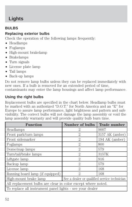
BULBSReplacing exterior bulbsCheck the operation of the following lamps frequently:• Headlamps• Foglamps• High-mount brakelamp• Brakelamps• Turn signals• License plate lamp• Tail lamps• Back-up lamps
Do not remove lamp bulbs unless they can be replaced immediately withnew ones. If a bulb is removed for an extended period of time,contaminants may enter the lamp housings and affect lamp performance.
Using the right bulbsReplacement bulbs are specified in the chart below. Headlamp bulbs mustbe marked with an authorized “D.O.T.” for North America and an “E” forEurope to assure lamp performance, light brightness and pattern and safevisibility. The correct bulbs will not damage the lamp assembly or void thelamp assembly warranty and will provide quality bulb burn time.
Function Number of bulbs Trade number
Headlamps 2 9007Front park/turn lamps 2 3157 AK (amber)Front sidemarker 2 194 AK (amber)Foglamps 2 800Dome/map lamps 2 579Turn/tail/brake lamps 2 3157KLiftgate lamp 2 916Backup lamp 2 579License lamp 2 168Running board lamp (if equipped) 2 168High-mount brake lamp See a dealer or qualified service technicianAll replacement bulbs are clear in color except where noted.To replace all instrument panel lights - see your dealer
Lights
52
Replacing the interior bulbsCheck the operation of the following interior bulbs frequently:
• interior overhead lamp
• map lamp
For bulb replacement, see a dealer or qualified technician.
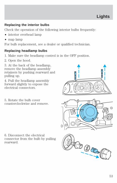
Replacing headlamp bulbs1. Make sure the headlamp control is in the OFF position.
2. Open the hood.
3. At the back of the headlamp,remove the headlamp assemblyretainers by pushing rearward andpulling up.
4. Pull the headlamp assemblyforward slightly to expose theelectrical connectors.
5. Rotate the bulb covercounterclockwise and remove.
6. Disconnect the electricalconnector from the bulb by pullingrearward.
Lights
53
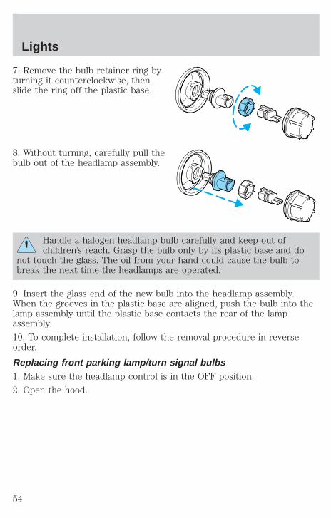
7. Remove the bulb retainer ring byturning it counterclockwise, thenslide the ring off the plastic base.
8. Without turning, carefully pull thebulb out of the headlamp assembly.
Handle a halogen headlamp bulb carefully and keep out ofchildren’s reach. Grasp the bulb only by its plastic base and do
not touch the glass. The oil from your hand could cause the bulb tobreak the next time the headlamps are operated.
9. Insert the glass end of the new bulb into the headlamp assembly.When the grooves in the plastic base are aligned, push the bulb into thelamp assembly until the plastic base contacts the rear of the lampassembly.
10. To complete installation, follow the removal procedure in reverseorder.
Replacing front parking lamp/turn signal bulbs1. Make sure the headlamp control is in the OFF position.
2. Open the hood.
Lights
54
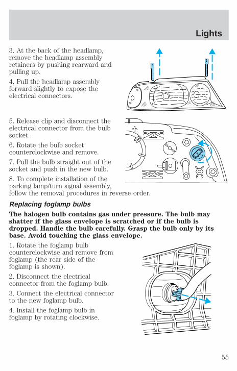
3. At the back of the headlamp,remove the headlamp assemblyretainers by pushing rearward andpulling up.
4. Pull the headlamp assemblyforward slightly to expose theelectrical connectors.
5. Release clip and disconnect theelectrical connector from the bulbsocket.
6. Rotate the bulb socketcounterclockwise and remove.
7. Pull the bulb straight out of thesocket and push in the new bulb.
8. To complete installation of theparking lamp/turn signal assembly,follow the removal procedures in reverse order.
Replacing foglamp bulbsThe halogen bulb contains gas under pressure. The bulb mayshatter if the glass envelope is scratched or if the bulb isdropped. Handle the bulb carefully. Grasp the bulb only by itsbase. Avoid touching the glass envelope.
1. Rotate the foglamp bulbcounterclockwise and remove fromfoglamp (the rear side of thefoglamp is shown).
2. Disconnect the electricalconnector from the foglamp bulb.
3. Connect the electrical connectorto the new foglamp bulb.
4. Install the foglamp bulb infoglamp by rotating clockwise.
Lights
55

Replacing tail lamp bulbs1. Open the liftgate to expose thelamp assembly screws.
2. Remove the two screws from thelamp assembly.
3. Carefully pry the lamp assemblyaway from the vehicle to expose thebulb socket.
4. Rotate the bulb socketcounterclockwise and remove fromlamp assembly.
5. Pull bulb straight out of socket and push in the new bulb.
6. Install the bulb socket into the lamp assembly and rotate clockwise.
7. Install the lamp assembly on the vehicle and secure with two screws.
Replacing liftgate tail lamp bulb1. Raise the liftgate and remove thelamp assembly nuts.
2. Carefully pull the lamp assemblyoutward to expose the electricalconnector.
Lights
56
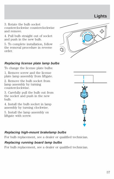
3. Rotate the bulb socketcounterclockwise counterclockwiseand remove.
4. Pull bulb straight out of socketand push in the new bulb.
5. To complete installation, followthe removal procedure in reverseorder.
Replacing license plate lamp bulbsTo change the license plate bulbs:
1. Remove screw and the licenseplate lamp assembly from liftgate.
2. Remove the bulb socket fromlamp assembly by turningcounterclockwise.
3. Carefully pull the bulb out fromthe socket and push in the newbulb.
4. Install the bulb socket in lampassembly by turning clockwise.
5. Install the lamp assembly onliftgate with screw.
Replacing high-mount brakelamp bulbsFor bulb replacement, see a dealer or qualified technician.
Replacing running board lamp bulbsFor bulb replacement, see a dealer or qualified technician.
Lights
57
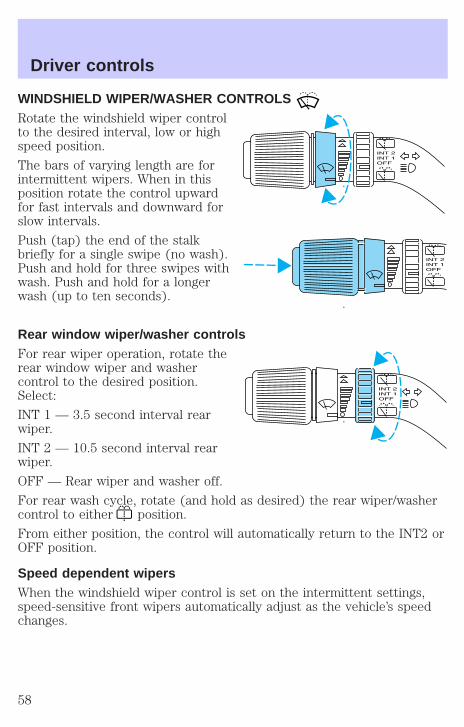
WINDSHIELD WIPER/WASHER CONTROLSRotate the windshield wiper controlto the desired interval, low or highspeed position.
The bars of varying length are forintermittent wipers. When in thisposition rotate the control upwardfor fast intervals and downward forslow intervals.
Push (tap) the end of the stalkbriefly for a single swipe (no wash).Push and hold for three swipes withwash. Push and hold for a longerwash (up to ten seconds).
Rear window wiper/washer controlsFor rear wiper operation, rotate therear window wiper and washercontrol to the desired position.Select:
INT 1 — 3.5 second interval rearwiper.
INT 2 — 10.5 second interval rearwiper.
OFF — Rear wiper and washer off.
For rear wash cycle, rotate (and hold as desired) the rear wiper/washercontrol to either position.
From either position, the control will automatically return to the INT2 orOFF position.
Speed dependent wipersWhen the windshield wiper control is set on the intermittent settings,speed-sensitive front wipers automatically adjust as the vehicle’s speedchanges.
Driver controls
58
Windshield wiper bladesCheck the wiper blades at least twice a year or when they seem lesseffective. Substances such as tree sap and some hot wax treatments usedby commercial car washes reduce the effectiveness of wiper blades.
Checking the wiper bladesIf the wiper blades do not wipe properly, clean both the windshield andwiper blades using undiluted windshield wiper solution or a milddetergent. Rinse thoroughly with clean water. To avoid damaging theblades, do not use fuel, kerosene, paint thinner or other solvents.
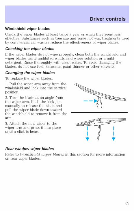
Changing the wiper bladesTo replace the wiper blades:
1. Pull the wiper arm away from thewindshield and lock into the serviceposition.
2. Turn the blade at an angle fromthe wiper arm. Push the lock pinmanually to release the blade andpull the wiper blade down towardthe windshield to remove it from thearm.
3. Attach the new wiper to thewiper arm and press it into placeuntil a click is heard.
Rear window wiper bladesRefer to Windshield wiper blades in this section for more informationon rear wiper blades.
Driver controls
59
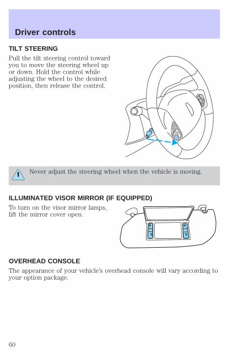
TILT STEERINGPull the tilt steering control towardyou to move the steering wheel upor down. Hold the control whileadjusting the wheel to the desiredposition, then release the control.
Never adjust the steering wheel when the vehicle is moving.
ILLUMINATED VISOR MIRROR (IF EQUIPPED)To turn on the visor mirror lamps,lift the mirror cover open.
OVERHEAD CONSOLEThe appearance of your vehicle’s overhead console will vary according toyour option package.
Driver controls
60

Forward storage bin (if equipped)Press the release control to openthe storage compartment. The doorwill open slightly and can be movedto full open.
The storage compartment may beused to secure sunglasses or asimilar object.
Installing a garage door opener (if equipped)The storage compartment can be converted to accommodate a variety ofaftermarket garage door openers:
• Place Velcro hook onto back side of aftermarket transmitter oppositeof actuator control.
• Place transmitter into storage compartment, control down.
• Place the provided height adaptors onto the back of the storage bindoor as needed.
• Press the storage compartment door to activate the transmitter.
Driver controls
61
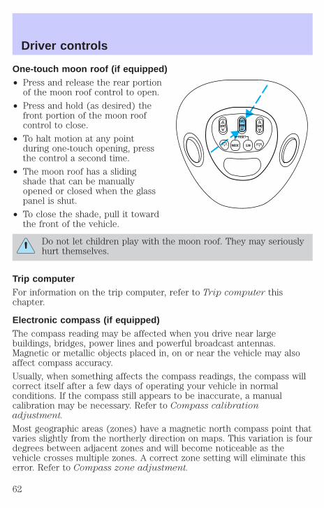
One-touch moon roof (if equipped)• Press and release the rear portion
of the moon roof control to open.
• Press and hold (as desired) thefront portion of the moon roofcontrol to close.
• To halt motion at any pointduring one-touch opening, pressthe control a second time.
• The moon roof has a slidingshade that can be manuallyopened or closed when the glasspanel is shut.
• To close the shade, pull it towardthe front of the vehicle.
Do not let children play with the moon roof. They may seriouslyhurt themselves.
Trip computerFor information on the trip computer, refer to Trip computer thischapter.
Electronic compass (if equipped)The compass reading may be affected when you drive near largebuildings, bridges, power lines and powerful broadcast antennas.Magnetic or metallic objects placed in, on or near the vehicle may alsoaffect compass accuracy.
Usually, when something affects the compass readings, the compass willcorrect itself after a few days of operating your vehicle in normalconditions. If the compass still appears to be inaccurate, a manualcalibration may be necessary. Refer to Compass calibrationadjustment.
Most geographic areas (zones) have a magnetic north compass point thatvaries slightly from the northerly direction on maps. This variation is fourdegrees between adjacent zones and will become noticeable as thevehicle crosses multiple zones. A correct zone setting will eliminate thiserror. Refer to Compass zone adjustment.
VENTVENT ROOF
Driver controls
62
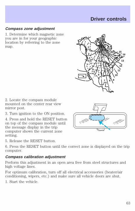
Compass zone adjustment1. Determine which magnetic zoneyou are in for your geographiclocation by referring to the zonemap.
2. Locate the compass modulemounted on the center rear viewmirror post.
3. Turn ignition to the ON position.
4. Press and hold the RESET buttonon top of the compass module untilthe message display in the tripcomputer shows the current zonesetting.
5. Release the RESET button.
6. Press the RESET button until the correct zone is displayed on the tripcomputer.
Compass calibration adjustmentPerform this adjustment in an open area free from steel structures andhigh voltage lines.
For optimum calibration, turn off all electrical accessories (heater/airconditioning, wipers, etc.) and make sure all vehicle doors are shut.
1. Start the vehicle.
1
2
3
4
56
7 8 9
10
11
12
13
1415
Driver controls
63
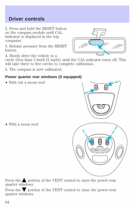
2. Press and hold the RESET buttonon the compass module until CALindicator is displayed in the tripcomputer.
3. Release pressure from the RESETbutton.
4. Slowly drive the vehicle in acircle (less than 5 km/h [3 mph]) until the CAL indicator turns off. Thiswill take three to five circles to complete calibration.
5. The compass is now calibrated.
Power quarter rear windows (if equipped)• With out a moon roof
• With a moon roof
Press the portion of the VENT control to open the power rearquarter windows.
Press the portion of the VENT control to close the power rearquarter windows.
RESET
VENT VENT
MODE E/M
VENTVENT ROOF
Driver controls
64

CLOCKPress H to set the hour.
Press M to set the minute.
AUXILIARY POWER POINTPower outlets are designed foraccessory plugs only. Do nothang any type of accessory oraccessory bracket from the plug.Improper use of the poweroutlet can cause damage not covered by your warranty.
The auxiliary power point is located on the instrument panel.
Do not plug optional electrical accessories into the cigarette lighter. Usethe power point.
Driver controls
65
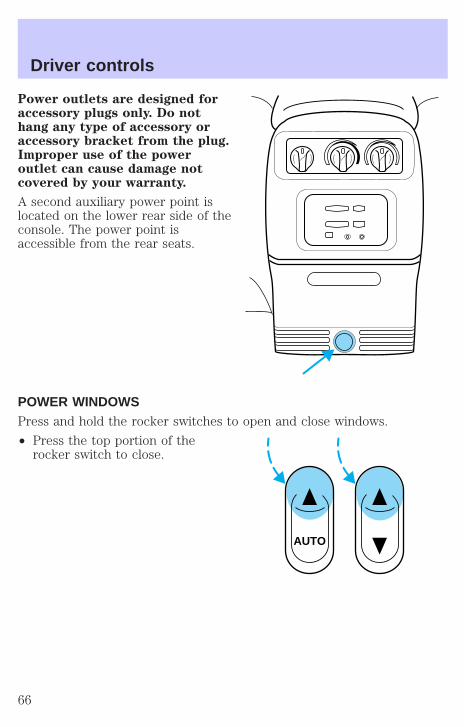
Power outlets are designed foraccessory plugs only. Do nothang any type of accessory oraccessory bracket from the plug.Improper use of the poweroutlet can cause damage notcovered by your warranty.
A second auxiliary power point islocated on the lower rear side of theconsole. The power point isaccessible from the rear seats.
POWER WINDOWSPress and hold the rocker switches to open and close windows.
• Press the top portion of therocker switch to close.
AUTO
Driver controls
66
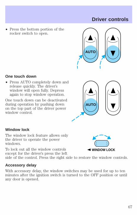
• Press the bottom portion of therocker switch to open.
One touch down• Press AUTO completely down and
release quickly. The driver’swindow will open fully. Depressagain to stop window operation.
One touch down can be deactivatedduring operation by pushing downon the top part of the driver powerwindow control.
Window lockThe window lock feature allows onlythe driver to operate the powerwindows.
To lock out all the window controlsexcept for the driver’s press the leftside of the control. Press the right side to restore the window controls.
Accessory delayWith accessory delay, the window switches may be used for up to tenminutes after the ignition switch is turned to the OFF position or untilany door is opened.
AUTO
AUTO
WINDOW LOCK
Driver controls
67

MIRRORS
Automatic dimming rear view mirrorYour vehicle is equipped with an inside rear view mirror with anauto-dimming function. The electronic day/night mirror will change fromthe normal state to the non-glare state when bright lights (glare) reachthe inside rear view mirror. When the inside rear view mirror detectsbright light from in front of or behind the vehicle, the inside rear viewmirror will automatically adjust (darken) to minimize glare.
Do not block the sensor on the backside of the inside rear view mirrorsince this may impair proper system performance.
Press the control to turn the mirrorOFF or AUTO.
The mirror will automatically returnto the normal state whenever thevehicle is placed in R(Reverse)(when the mirror is on) to ensure a bright clear view whenbacking up.
Power side view mirrorsThe ignition can be in any position to adjust the power side view mirrors.
To adjust your mirrors:
1. Select L to adjust the left mirroror R to adjust the right mirror.
OFF AUTO
MIRRORS
L R
Driver controls
68
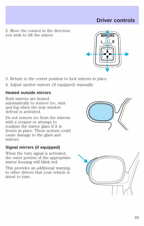
2. Move the control in the directionyou wish to tilt the mirror.
3. Return to the center position to lock mirrors in place.
4. Adjust spotter mirrors (if equipped) manually.
Heated outside mirrorsBoth mirrors are heatedautomatically to remove ice, mistand fog when the rear windowdefrost is activated.
Do not remove ice from the mirrorswith a scraper or attempt toreadjust the mirror glass if it isfrozen in place. These actions couldcause damage to the glass andmirrors.
Signal mirrors (if equipped)When the turn signal is activated,the outer portion of the appropriatemirror housing will blink red.
This provides an additional warningto other drivers that your vehicle isabout to turn.
MIRRORS
L R
Driver controls
69
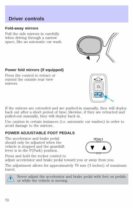
Fold-away mirrorsPull the side mirrors in carefullywhen driving through a narrowspace, like an automatic car wash.
Power fold mirrors (if equipped)Press the control to retract orextend the outside rear viewmirrors.
If the mirrors are extended and are pushed-in manually, they will deployback out after a short period of time; likewise, if they are retracted andpulled-out manually, they will deploy back in.
Use caution in certain instances (i.e. automatic car washes) in order toavoid damage to the mirrors.
POWER ADJUSTABLE FOOT PEDALSThe accelerator and brake pedalshould only be adjusted when thevehicle is stopped and the gearshiftlever is in the P(Park) position.
Press and hold the rocker control toadjust accelerator and brake pedal toward you or away from you.
The adjustment allows for approximately 76 mm (3 inches) of maximumtravel.
Never adjust the accelerator and brake pedal with feet on pedalsor while the vehicle is moving.
PEDALS
Driver controls
70
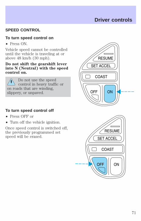
SPEED CONTROL
To turn speed control on• Press ON.
Vehicle speed cannot be controlleduntil the vehicle is traveling at orabove 48 km/h (30 mph).
Do not shift the gearshift leverinto N (Neutral) with the speedcontrol on.
Do not use the speedcontrol in heavy traffic or
on roads that are winding,slippery, or unpaved.
To turn speed control off• Press OFF or
• Turn off the vehicle ignition.
Once speed control is switched off,the previously programmed setspeed will be erased.
Driver controls
71
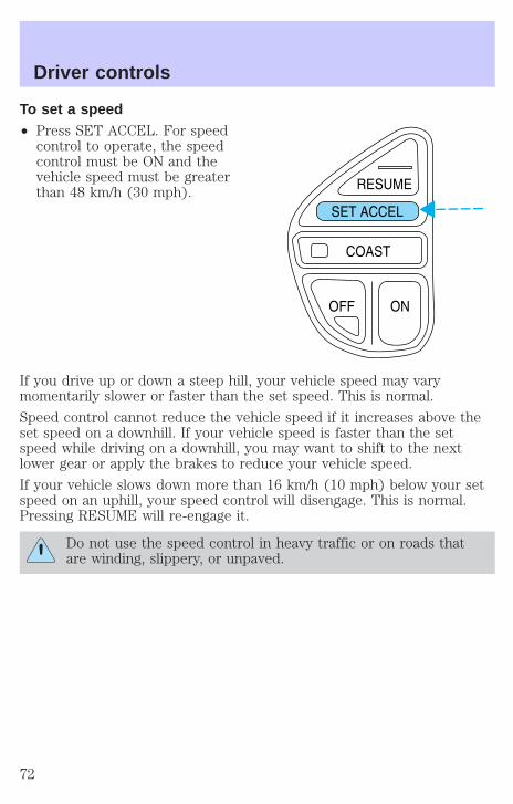
To set a speed• Press SET ACCEL. For speed
control to operate, the speedcontrol must be ON and thevehicle speed must be greaterthan 48 km/h (30 mph).
If you drive up or down a steep hill, your vehicle speed may varymomentarily slower or faster than the set speed. This is normal.
Speed control cannot reduce the vehicle speed if it increases above theset speed on a downhill. If your vehicle speed is faster than the setspeed while driving on a downhill, you may want to shift to the nextlower gear or apply the brakes to reduce your vehicle speed.
If your vehicle slows down more than 16 km/h (10 mph) below your setspeed on an uphill, your speed control will disengage. This is normal.Pressing RESUME will re-engage it.
Do not use the speed control in heavy traffic or on roads thatare winding, slippery, or unpaved.
Driver controls
72
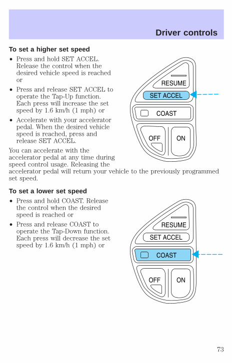
To set a higher set speed• Press and hold SET ACCEL.
Release the control when thedesired vehicle speed is reachedor
• Press and release SET ACCEL tooperate the Tap-Up function.Each press will increase the setspeed by 1.6 km/h (1 mph) or
• Accelerate with your acceleratorpedal. When the desired vehiclespeed is reached, press andrelease SET ACCEL.
You can accelerate with theaccelerator pedal at any time duringspeed control usage. Releasing theaccelerator pedal will return your vehicle to the previously programmedset speed.
To set a lower set speed• Press and hold COAST. Release
the control when the desiredspeed is reached or
• Press and release COAST tooperate the Tap-Down function.Each press will decrease the setspeed by 1.6 km/h (1 mph) or
Driver controls
73
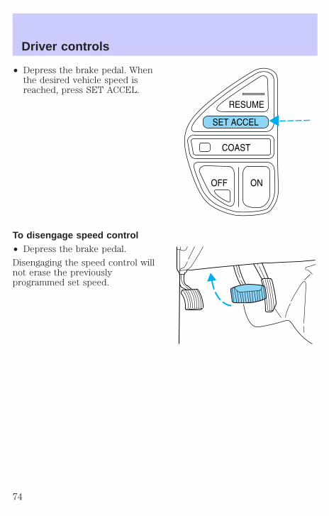
• Depress the brake pedal. Whenthe desired vehicle speed isreached, press SET ACCEL.
To disengage speed control• Depress the brake pedal.
Disengaging the speed control willnot erase the previouslyprogrammed set speed.
Driver controls
74
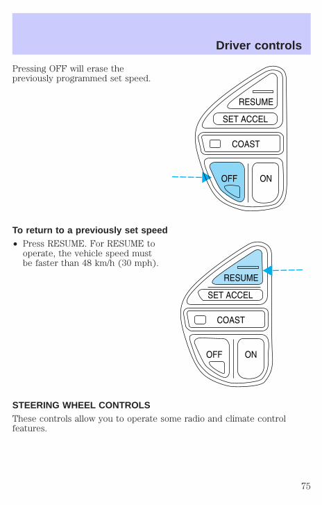
Pressing OFF will erase thepreviously programmed set speed.
To return to a previously set speed• Press RESUME. For RESUME to
operate, the vehicle speed mustbe faster than 48 km/h (30 mph).
STEERING WHEEL CONTROLSThese controls allow you to operate some radio and climate controlfeatures.
Driver controls
75
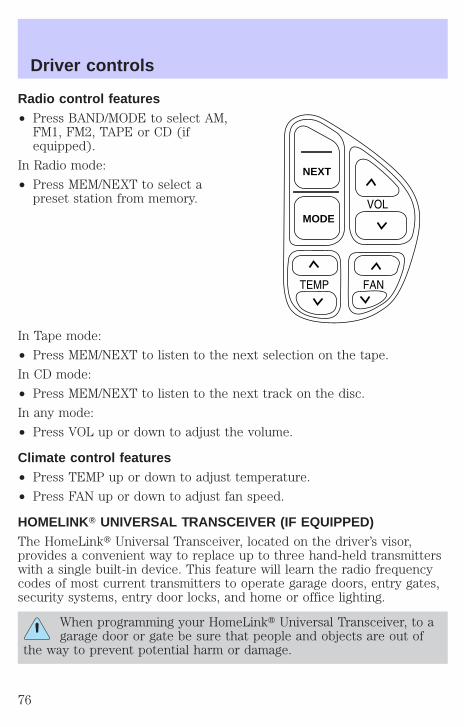
Radio control features• Press BAND/MODE to select AM,
FM1, FM2, TAPE or CD (ifequipped).
In Radio mode:
• Press MEM/NEXT to select apreset station from memory.
In Tape mode:
• Press MEM/NEXT to listen to the next selection on the tape.
In CD mode:
• Press MEM/NEXT to listen to the next track on the disc.
In any mode:
• Press VOL up or down to adjust the volume.
Climate control features• Press TEMP up or down to adjust temperature.
• Press FAN up or down to adjust fan speed.
HOMELINKT UNIVERSAL TRANSCEIVER (IF EQUIPPED)The HomeLinkt Universal Transceiver, located on the driver’s visor,provides a convenient way to replace up to three hand-held transmitterswith a single built-in device. This feature will learn the radio frequencycodes of most current transmitters to operate garage doors, entry gates,security systems, entry door locks, and home or office lighting.
When programming your HomeLinkt Universal Transceiver, to agarage door or gate be sure that people and objects are out of
the way to prevent potential harm or damage.
NEXT
MODE
Driver controls
76
Do not use the HomeLinkt Universal Transceiver with any garage dooropener that lacks safety stop and reverse features as required by U.S.federal safety standards (this includes any garage door opener modelmanufactured before April 1, 1982). A garage door which cannot detectan object, signaling the door to stop and reverse, does not meet currentU.S. federal safety standards. For more information on this matter, calltoll-free: 1–800–355–3515 or on the Internet at HomeLink.jci.com.
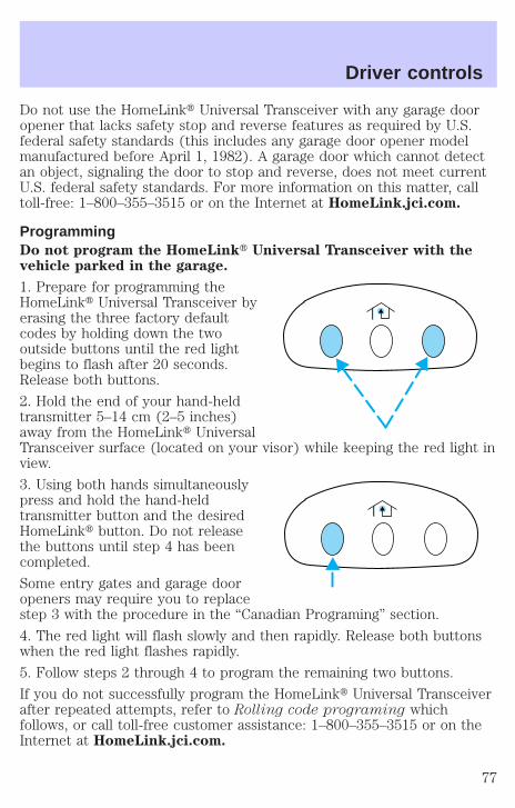
ProgrammingDo not program the HomeLinkt Universal Transceiver with thevehicle parked in the garage.
1. Prepare for programming theHomeLinkt Universal Transceiver byerasing the three factory defaultcodes by holding down the twooutside buttons until the red lightbegins to flash after 20 seconds.Release both buttons.
2. Hold the end of your hand-heldtransmitter 5–14 cm (2–5 inches)away from the HomeLinkt UniversalTransceiver surface (located on your visor) while keeping the red light inview.
3. Using both hands simultaneouslypress and hold the hand-heldtransmitter button and the desiredHomeLinkt button. Do not releasethe buttons until step 4 has beencompleted.
Some entry gates and garage dooropeners may require you to replacestep 3 with the procedure in the “Canadian Programing” section.
4. The red light will flash slowly and then rapidly. Release both buttonswhen the red light flashes rapidly.
5. Follow steps 2 through 4 to program the remaining two buttons.
If you do not successfully program the HomeLinkt Universal Transceiverafter repeated attempts, refer to Rolling code programing whichfollows, or call toll-free customer assistance: 1–800–355–3515 or on theInternet at HomeLink.jci.com.
Driver controls
77

Canadian ProgrammingDuring programming, your hand-held transmitter may automatically stoptransmitting after two seconds which may not be long enough toprogram the HomeLinkt Universal Transceiver.
To program your hand-heldtransmitters:
• Continue to hold the button onthe HomeLinkt UniversalTransceiver.
• Press and re-press the hand-heldtransmitter button every twoseconds until the red light changes from a slow to a fast flash.
Operating the HomeLink T Universal TransceiverOnce programmed, the HomeLinktUniversal Transceiver can be used inplace of hand-held transmitters. Tooperate, simply press and release theappropriate HomeLinkt button (thered light will illuminate, indicatingthe signal is being transmitted).
Rolling code programmingRolling code garage door openers (or other rolling code devices) whichare “code protected” and manufactured after 1996, may be determinedby the following:
• Reference the device owner’s manual for verification
• The hand-held transmitter appears to program the HomeLinktUniversal Transceiver but does not activate the device.
• Press and hold the trained HomeLinkt button. The device has therolling code feature if the indicator light flashes rapidly and then turnssolid after two seconds.
After completing the “Programming” functions, follow these steps totrain a garage door opener with the rolling code feature:
1. Locate the training button on the garage door motor head unit.Refer to the garage door opener manual or call 1–800–355–3515 or onthe Internet at HomeLink.jci.com. if there is difficulty locating thetraining button.
Driver controls
78
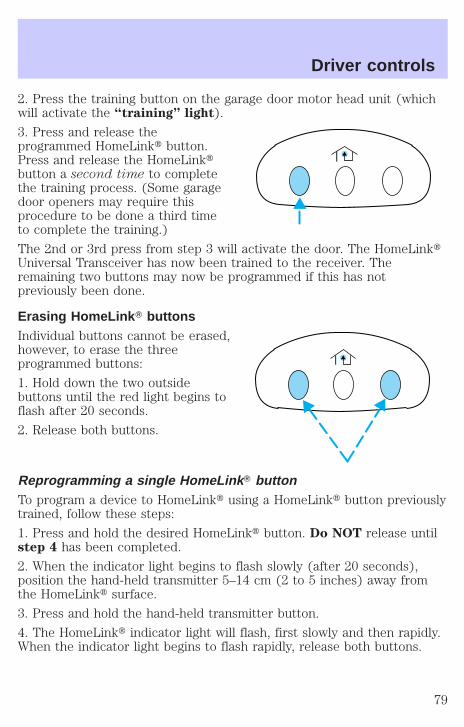
2. Press the training button on the garage door motor head unit (whichwill activate the “training” light).
3. Press and release theprogrammed HomeLinkt button.Press and release the HomeLinktbutton a second time to completethe training process. (Some garagedoor openers may require thisprocedure to be done a third timeto complete the training.)
The 2nd or 3rd press from step 3 will activate the door. The HomeLinktUniversal Transceiver has now been trained to the receiver. Theremaining two buttons may now be programmed if this has notpreviously been done.
Erasing HomeLink T buttonsIndividual buttons cannot be erased,however, to erase the threeprogrammed buttons:
1. Hold down the two outsidebuttons until the red light begins toflash after 20 seconds.
2. Release both buttons.
Reprogramming a single HomeLink T buttonTo program a device to HomeLinkt using a HomeLinkt button previouslytrained, follow these steps:
1. Press and hold the desired HomeLinkt button. Do NOT release untilstep 4 has been completed.
2. When the indicator light begins to flash slowly (after 20 seconds),position the hand-held transmitter 5–14 cm (2 to 5 inches) away fromthe HomeLinkt surface.
3. Press and hold the hand-held transmitter button.
4. The HomeLinkt indicator light will flash, first slowly and then rapidly.When the indicator light begins to flash rapidly, release both buttons.
Driver controls
79
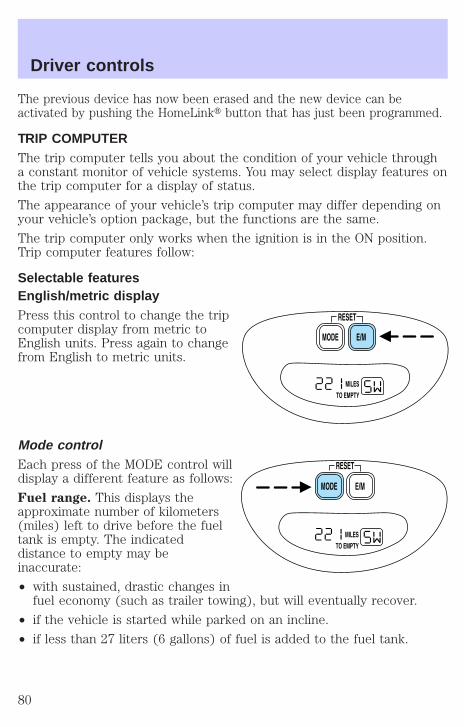
The previous device has now been erased and the new device can beactivated by pushing the HomeLinkt button that has just been programmed.
TRIP COMPUTERThe trip computer tells you about the condition of your vehicle througha constant monitor of vehicle systems. You may select display features onthe trip computer for a display of status.
The appearance of your vehicle’s trip computer may differ depending onyour vehicle’s option package, but the functions are the same.
The trip computer only works when the ignition is in the ON position.Trip computer features follow:
Selectable featuresEnglish/metric displayPress this control to change the tripcomputer display from metric toEnglish units. Press again to changefrom English to metric units.
Mode controlEach press of the MODE control willdisplay a different feature as follows:
Fuel range. This displays theapproximate number of kilometers(miles) left to drive before the fueltank is empty. The indicateddistance to empty may beinaccurate:
• with sustained, drastic changes infuel economy (such as trailer towing), but will eventually recover.
• if the vehicle is started while parked on an incline.
• if less than 27 liters (6 gallons) of fuel is added to the fuel tank.
Driver controls
80
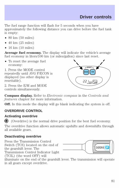
The fuel range function will flash for 5 seconds when you haveapproximately the following distance you can drive before the fuel tankis empty:
• 80 km (50 miles)
• 40 km (25 miles)
• 16 km (10 miles)
Average fuel economy. The display will indicate the vehicle’s averagefuel economy in liters/100 km (or miles/gallon) since last reset.
• To reset the average fueleconomy:
1. Press the MODE controlrepeatedly until AVG F/ECON isdisplayed (no other display isresettable).
2. Press the E/M and MODEcontrols simultaneously.
Compass display. Refer to Electronic compass in the Controls andfeatures chapter for more information.
Off. In this mode the display will go blank indicating the system is off.
OVERDRIVE CONTROL
Activating overdrive(Overdrive) is the normal drive position for the best fuel economy.
The overdrive function allows automatic upshifts and downshifts throughall available gears.
Deactivating overdrivePress the Transmission ControlSwitch (TCS) located on the end ofthe gearshift lever. TheTransmission Control Indicator Light(TCIL) (the word OFF) willilluminate on the end of the gearshift lever. The transmission will operatein all gears except overdrive.
OVERDRIVE
Driver controls
81
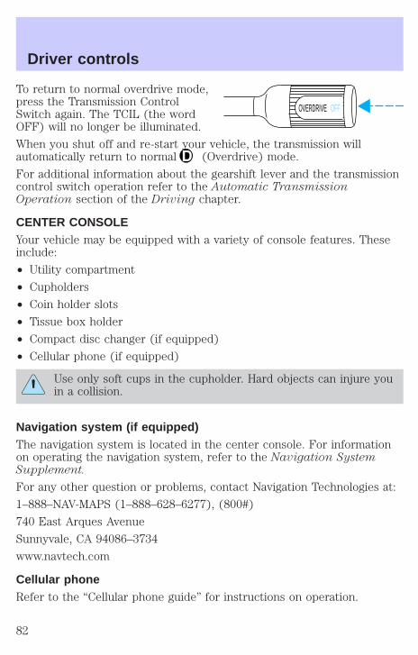
To return to normal overdrive mode,press the Transmission ControlSwitch again. The TCIL (the wordOFF) will no longer be illuminated.
When you shut off and re-start your vehicle, the transmission willautomatically return to normal (Overdrive) mode.
For additional information about the gearshift lever and the transmissioncontrol switch operation refer to the Automatic TransmissionOperation section of the Driving chapter.
CENTER CONSOLEYour vehicle may be equipped with a variety of console features. Theseinclude:
• Utility compartment
• Cupholders
• Coin holder slots
• Tissue box holder
• Compact disc changer (if equipped)
• Cellular phone (if equipped)
Use only soft cups in the cupholder. Hard objects can injure youin a collision.
Navigation system (if equipped)The navigation system is located in the center console. For informationon operating the navigation system, refer to the Navigation SystemSupplement.
For any other question or problems, contact Navigation Technologies at:
1–888–NAV-MAPS (1–888–628–6277), (800#)
740 East Arques Avenue
Sunnyvale, CA 94086–3734
www.navtech.com
Cellular phoneRefer to the “Cellular phone guide” for instructions on operation.
OVERDRIVE OFF
Driver controls
82
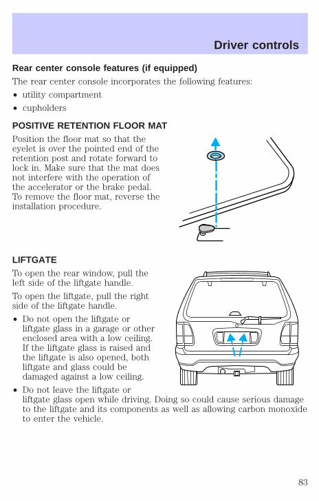
Rear center console features (if equipped)The rear center console incorporates the following features:
• utility compartment
• cupholders
POSITIVE RETENTION FLOOR MATPosition the floor mat so that theeyelet is over the pointed end of theretention post and rotate forward tolock in. Make sure that the mat doesnot interfere with the operation ofthe accelerator or the brake pedal.To remove the floor mat, reverse theinstallation procedure.
LIFTGATETo open the rear window, pull theleft side of the liftgate handle.
To open the liftgate, pull the rightside of the liftgate handle.
• Do not open the liftgate orliftgate glass in a garage or otherenclosed area with a low ceiling.If the liftgate glass is raised andthe liftgate is also opened, bothliftgate and glass could bedamaged against a low ceiling.
• Do not leave the liftgate orliftgate glass open while driving. Doing so could cause serious damageto the liftgate and its components as well as allowing carbon monoxideto enter the vehicle.
Driver controls
83
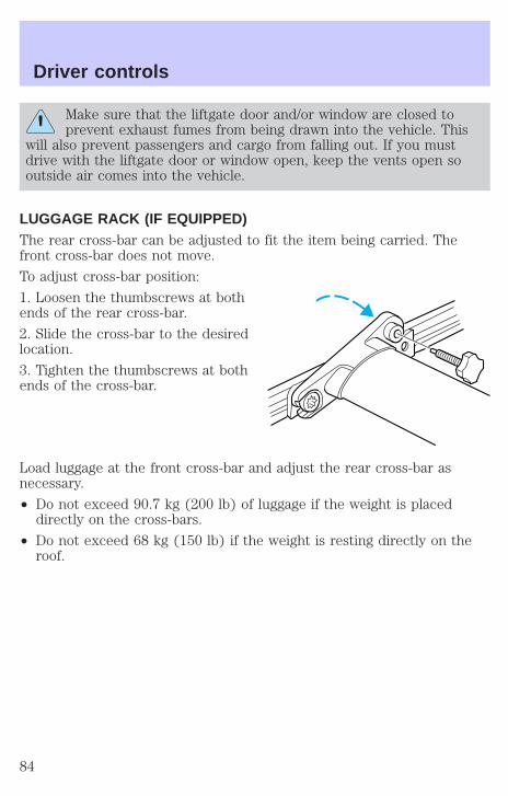
Make sure that the liftgate door and/or window are closed toprevent exhaust fumes from being drawn into the vehicle. This
will also prevent passengers and cargo from falling out. If you mustdrive with the liftgate door or window open, keep the vents open sooutside air comes into the vehicle.
LUGGAGE RACK (IF EQUIPPED)The rear cross-bar can be adjusted to fit the item being carried. Thefront cross-bar does not move.
To adjust cross-bar position:
1. Loosen the thumbscrews at bothends of the rear cross-bar.
2. Slide the cross-bar to the desiredlocation.
3. Tighten the thumbscrews at bothends of the cross-bar.
Load luggage at the front cross-bar and adjust the rear cross-bar asnecessary.
• Do not exceed 90.7 kg (200 lb) of luggage if the weight is placeddirectly on the cross-bars.
• Do not exceed 68 kg (150 lb) if the weight is resting directly on theroof.
Driver controls
84
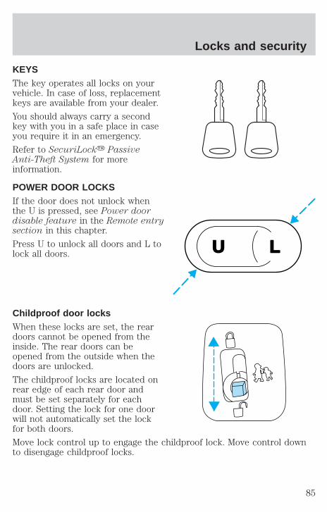
KEYSThe key operates all locks on yourvehicle. In case of loss, replacementkeys are available from your dealer.
You should always carry a secondkey with you in a safe place in caseyou require it in an emergency.
Refer to SecuriLocky PassiveAnti-Theft System for moreinformation.
POWER DOOR LOCKSIf the door does not unlock whenthe U is pressed, see Power doordisable feature in the Remote entrysection in this chapter.
Press U to unlock all doors and L tolock all doors.
Childproof door locksWhen these locks are set, the reardoors cannot be opened from theinside. The rear doors can beopened from the outside when thedoors are unlocked.
The childproof locks are located onrear edge of each rear door andmust be set separately for eachdoor. Setting the lock for one doorwill not automatically set the lockfor both doors.
Move lock control up to engage the childproof lock. Move control downto disengage childproof locks.
U L
Locks and security
85
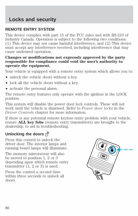
REMOTE ENTRY SYSTEMThis device complies with part 15 of the FCC rules and with RS-210 ofIndustry Canada. Operation is subject to the following two conditions:(1) This device may not cause harmful interference, and (2) This devicemust accept any interference received, including interference that maycause undesired operation.
Changes or modifications not expressly approved by the partyresponsible for compliance could void the user’s authority tooperate the equipment.
Your vehicle is equipped with a remote entry system which allows you to:
• unlock the vehicle doors without a key.
• lock all the vehicle doors without a key.
• activate the personal alarm.
The remote entry features only operate with the ignition in the LOCKposition.
This system will disable the power door lock controls. These will notwork until the vehicle is disarmed. Refer to Power door locks in theDriver Controls chapter for more information.
If there is any potential remote keyless entry problem with your vehicle,ensure ALL key fobs (remote entry transmitters) are brought to thedealership, to aid in troubleshooting.
Unlocking the doorsPress this control to unlock thedriver door. The interior lamps andrunning board lamps will illuminate.
The memory mirrors/seat will alsobe moved to position 1, 2 or 3depending upon which remote entrytransmitter (1, 2 or 3) is used.
Press the control a second timewithin three seconds to unlock alldoors.
Locks and security
86
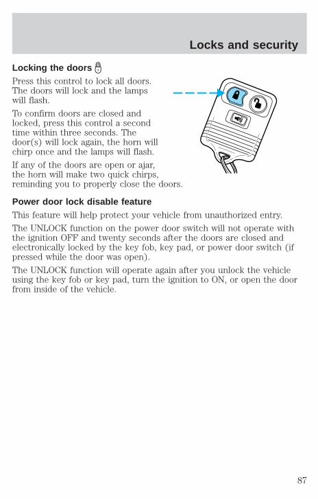
Locking the doorsPress this control to lock all doors.The doors will lock and the lampswill flash.
To confirm doors are closed andlocked, press this control a secondtime within three seconds. Thedoor(s) will lock again, the horn willchirp once and the lamps will flash.
If any of the doors are open or ajar,the horn will make two quick chirps,reminding you to properly close the doors.
Power door lock disable featureThis feature will help protect your vehicle from unauthorized entry.
The UNLOCK function on the power door switch will not operate withthe ignition OFF and twenty seconds after the doors are closed andelectronically locked by the key fob, key pad, or power door switch (ifpressed while the door was open).
The UNLOCK function will operate again after you unlock the vehicleusing the key fob or key pad, turn the ignition to ON, or open the doorfrom inside of the vehicle.
Locks and security
87

Deactivating/activating power door lock disable feature1. Turn the ignition key to ON, thenpress the UNLOCK button 3 times.
2. Turn the ignition key to OFF,then press the UNLOCK button 3times.
3. Turn the ignition key to ON,within five seconds press the LOCKbutton 2 times.
The user should receive 2 hornchirps to indicate the system has been disabled or 2 chirps followed bya honk to indicate the system has been enabled.
Pressing the power door LOCK button 2 times again will toggle the trimswitch inhibit states.
Turn ignition to OFF to exit programming.
Sounding a panic alarmPress this control to activate thealarm.
To deactivate the alarm, press thecontrol again or turn the ignition toACC or ON.
Panic alarm will only operate withthe ignition in the OFF position.
Replacing the batteryThe remote transmitter is powered by one coin type three-volt lithiumbattery CR2032 or equivalent. Typical operating range will allow you tobe up to 10 meters (33 feet) away from your vehicle. A decrease inoperating range can be caused by:
• weather conditions
• nearby radio towers
• structures around the vehicle
• other vehicles parked next to the vehicle
U L
Locks and security
88
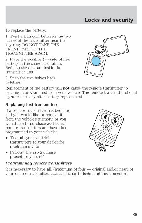
To replace the battery:
1. Twist a thin coin between the twohalves of the transmitter near thekey ring. DO NOT TAKE THEFRONT PART OF THETRANSMITTER APART.
2. Place the positive (+) side of newbattery in the same orientation.Refer to the diagram inside thetransmitter unit.
3. Snap the two halves backtogether.
Replacement of the battery will not cause the remote transmitter tobecome deprogrammed from your vehicle. The remote transmitter shouldoperate normally after battery replacement.
Replacing lost transmittersIf a remote transmitter has been lostand you would like to remove itfrom the vehicle’s memory, or youwould like to purchase additionalremote transmitters and have themprogrammed to your vehicle:
• Take all your vehicle’stransmitters to your dealer forprogramming, or
• Perform the programmingprocedure yourself
Programming remote transmittersIt is necessary to have all (maximum of four — original and/or new) ofyour remote transmitters available prior to beginning this procedure.
Locks and security
89
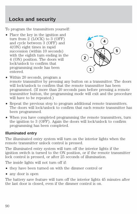
To program the transmitters yourself:
• Place the key in the ignition andturn from 2 (LOCK) to 3 (OFF)and cycle between 3 (OFF) and4(ON) eight times in rapidsuccession (within 10 seconds)with the eighth turn ending in the4 (ON) position. The doors willlock/unlock to confirm thatprogramming mode has beenentered.
• Within 20 seconds, program aremote transmitter by pressing any button on a transmitter. The doorswill lock/unlock to confirm that the remote transmitter has beenprogrammed. (If more than 20 seconds pass before pressing a remotetransmitter button, the programming mode will exit and the procedurewill have to be repeated.)
• Repeat the previous step to program additional remote transmitters.The doors will lock/unlock to confirm that each remote transmitter hasbeen programmed.
• When you have completed programming the remote transmitters, turnthe ignition to 3 (OFF). Again the doors will lock/unlock to confirmprogramming has been completed.
Illuminated entryThe illuminated entry system will turn on the interior lights when theremote transmitter unlock control is pressed.
The illuminated entry system will turn off the interior lights if theignition switch is turned to the ON position, or if the remote transmitterlock control is pressed, or after 25 seconds of illumination.
The inside lights will not turn off if:
• they have been turned on with the dimmer control or
• any door is open
The battery save feature will turn off the interior lights 45 minutes afterthe last door is closed, even if the dimmer control is on.
3
2
1
5
4
Locks and security
90

Memory seat/mirrors/adjustable pedal featureThe memory feature allows automatic positioning of the driver seat, sidemirrors and adjustable pedals to three programmable positions.
• To program position one, move the driver seat, both side mirrors, andadjustable pedals to the desired positions. Press the SET control. TheSET control indicator light will briefly illuminate. While the light isilluminated, press control 1.
• To program position two, repeat the previous procedure using control2.
• To program position three, repeat the previous procedure but presscontrols 1 and 2 simultaneously.
The memory feature also allows you to recall previously stored positionswith your remote transmitter(s). Up to three remote transmitters can beactivated to utilize the memory recall positions.
Press the memory feature control to move to the previously storedseat/mirror/adjustable pedal positions.
Activating/deactivating the memory feature on your remotetransmitterThe memory feature from the remote transmitter can be turned off/on,however, the memory control buttons will continue to operate. Beforefollowing the procedure, make sure that the ignition is OFF and all doorsand the liftgate window are closed. You must complete steps 1–7 within30 seconds or the procedure will have to be repeated. If the procedureneeds to be repeated, you must wait 30 seconds.
1. Turn the ignition key to ON.
2. Press the power door unlock control three times.
3. Turn the ignition key from ON to OFF.
4. Press the power door unlock control three times.
5. Turn the ignition back to ON. The horn will chirp.
6. Press the power door unlock control two times, then press the powerlock control once. The horn will chirp twice if the memory feature wasdeactivated or three times (two short and one long chirp) if the memoryfeature was activated.
7. Turn ignition to OFF. The horn will chirp once to confirm theprocedure is complete.
Locks and security
91
Autolock (if equipped)This feature automatically locks all vehicle doors when:
• all doors, liftgate and liftgate window are closed
• the engine is running
• you shift into any gear putting the vehicle in motion.
RelockThe autolock feature repeats when:
• any door, except the drivers, is opened then closed while the engine isrunning and
• you put the vehicle in motion.
Deactivating/activating the autolock featureBefore following the procedure, make sure that the ignition is OFF andall vehicle doors and the liftgate window are closed.
You must complete steps 1-7 within 30 seconds or the procedure willhave to be repeated. If the procedure needs to be repeated, you mustwait 30 seconds.
1. Turn the ignition key to ON.
2. Press the power door unlock control three times.
3. Turn the ignition key from ON to OFF.
4. Press the power door unlock control three times.
5. Turn the ignition back to ON. The horn will chirp.
6. Press the unlock control, then press the lock control. The horn willchirp once if autolock was deactivated or twice (one short and one longchirp) if autolock was activated.
7. Turn the ignition to OFF. The horn will chirp once to confirm theprocedure is complete.
KEYLESS ENTRY SYSTEMWith the keyless entry keypad, you can:
• lock or unlock the vehicle doors without using the key.
Your vehicle has a factory set 5 digit code that operates the keyless entrysystem. You can also program your own 5 digit personal entry code. Thefactory-set code is located:
Locks and security
92
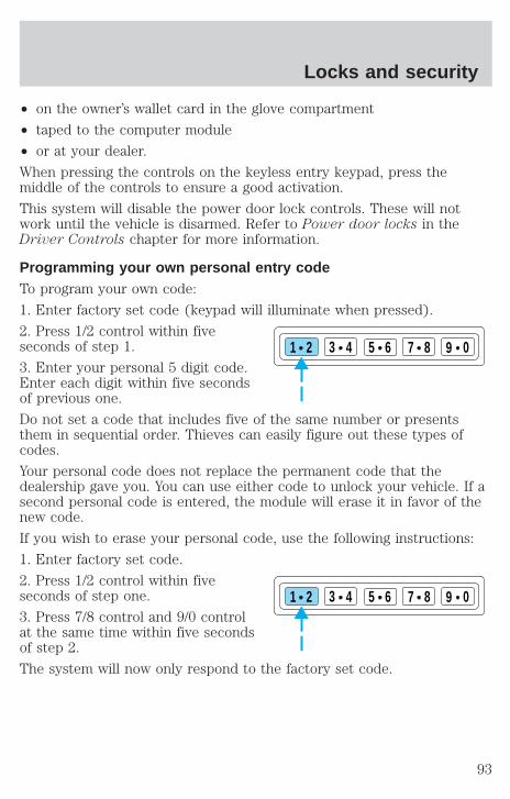
• on the owner’s wallet card in the glove compartment
• taped to the computer module
• or at your dealer.
When pressing the controls on the keyless entry keypad, press themiddle of the controls to ensure a good activation.
This system will disable the power door lock controls. These will notwork until the vehicle is disarmed. Refer to Power door locks in theDriver Controls chapter for more information.
Programming your own personal entry codeTo program your own code:
1. Enter factory set code (keypad will illuminate when pressed).
2. Press 1/2 control within fiveseconds of step 1.
3. Enter your personal 5 digit code.Enter each digit within five secondsof previous one.
Do not set a code that includes five of the same number or presentsthem in sequential order. Thieves can easily figure out these types ofcodes.
Your personal code does not replace the permanent code that thedealership gave you. You can use either code to unlock your vehicle. If asecond personal code is entered, the module will erase it in favor of thenew code.
If you wish to erase your personal code, use the following instructions:
1. Enter factory set code.
2. Press 1/2 control within fiveseconds of step one.
3. Press 7/8 control and 9/0 controlat the same time within five secondsof step 2.
The system will now only respond to the factory set code.
1 2 3 4 5 6 7 8 9 0
1 2 3 4 5 6 7 8 9 0
Locks and security
93

Anti-scan featureThe keyless entry pad is disabled for1 minute after 7 unsuccessfulattempts at entering a valid keycode. The keypad will flash duringthis 1 minute mode. However, the 7/8 and 9/0 controls will still lock thevehicle.
Anti-scan will turned off after:
• one minute of keypad inactivity
• the keyfob UNLOCK button is pressed.
• the ignition is turned to the ON position
Unlocking the doors with the keyless entry systemTo unlock the driver door, entereither the factory set code or thepersonal code (each digit must bepressed within five seconds of theprior digit). The interior lamps willalso illuminate.
To unlock all doors, enter the factory set code or personal code (driverdoor unlocks) and press the 3/4 control within five seconds.
Locking the doors with the keyless entry systemIt is not necessary to enter thefactory or personal code prior tolocking all doors. To lock the doors:
• Press the 7/8 control and the 9/0control at the same time.
Activating/deactivating autolock with the keyless entry systemBefore following the activation ordeactivation procedures, make surethat the anti-theft system (ifequipped) is not armed, ignition isoff, and all vehicle doors and liftgate window are closed.
1. Enter 5 digit entry code
2. Press and hold 7/8 control
1 2 3 4 5 6 7 8 9 0
1 2 3 4 5 6 7 8 9 0
1 2 3 4 5 6 7 8 9 0
1 2 3 4 5 6 7 8 9 0
Locks and security
94
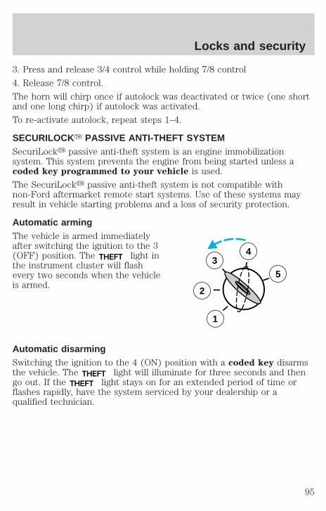
3. Press and release 3/4 control while holding 7/8 control
4. Release 7/8 control.
The horn will chirp once if autolock was deactivated or twice (one shortand one long chirp) if autolock was activated.
To re-activate autolock, repeat steps 1–4.
SECURILOCKY PASSIVE ANTI-THEFT SYSTEMSecuriLocky passive anti-theft system is an engine immobilizationsystem. This system prevents the engine from being started unless acoded key programmed to your vehicle is used.
The SecuriLocky passive anti-theft system is not compatible withnon-Ford aftermarket remote start systems. Use of these systems mayresult in vehicle starting problems and a loss of security protection.
Automatic armingThe vehicle is armed immediatelyafter switching the ignition to the 3(OFF) position. The THEFT light inthe instrument cluster will flashevery two seconds when the vehicleis armed.
Automatic disarmingSwitching the ignition to the 4 (ON) position with a coded key disarmsthe vehicle. The THEFT light will illuminate for three seconds and thengo out. If the THEFT light stays on for an extended period of time orflashes rapidly, have the system serviced by your dealership or aqualified technician.
3
2
1
5
4
Locks and security
95
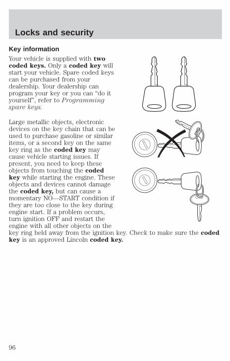
Key informationYour vehicle is supplied with twocoded keys. Only a coded key willstart your vehicle. Spare coded keyscan be purchased from yourdealership. Your dealership canprogram your key or you can “do ityourself”, refer to Programmingspare keys.
Large metallic objects, electronicdevices on the key chain that can beused to purchase gasoline or similaritems, or a second key on the samekey ring as the coded key maycause vehicle starting issues. Ifpresent, you need to keep theseobjects from touching the codedkey while starting the engine. Theseobjects and devices cannot damagethe coded key, but can cause amomentary NO—START condition ifthey are too close to the key duringengine start. If a problem occurs,turn ignition OFF and restart theengine with all other objects on thekey ring held away from the ignition key. Check to make sure the codedkey is an approved Lincoln coded key.
Locks and security
96
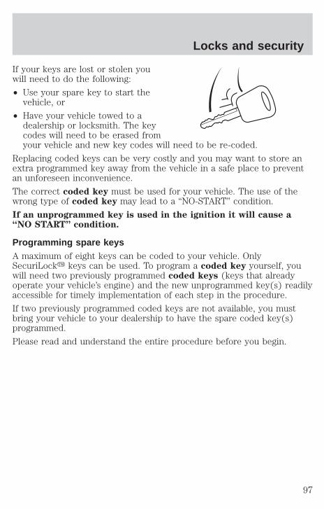
If your keys are lost or stolen youwill need to do the following:
• Use your spare key to start thevehicle, or
• Have your vehicle towed to adealership or locksmith. The keycodes will need to be erased fromyour vehicle and new key codes will need to be re-coded.
Replacing coded keys can be very costly and you may want to store anextra programmed key away from the vehicle in a safe place to preventan unforeseen inconvenience.
The correct coded key must be used for your vehicle. The use of thewrong type of coded key may lead to a “NO-START” condition.
If an unprogrammed key is used in the ignition it will cause a“NO START” condition.
Programming spare keysA maximum of eight keys can be coded to your vehicle. OnlySecuriLocky keys can be used. To program a coded key yourself, youwill need two previously programmed coded keys (keys that alreadyoperate your vehicle’s engine) and the new unprogrammed key(s) readilyaccessible for timely implementation of each step in the procedure.
If two previously programmed coded keys are not available, you mustbring your vehicle to your dealership to have the spare coded key(s)programmed.
Please read and understand the entire procedure before you begin.
Locks and security
97
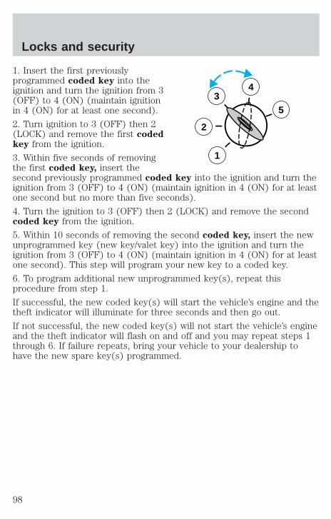
1. Insert the first previouslyprogrammed coded key into theignition and turn the ignition from 3(OFF) to 4 (ON) (maintain ignitionin 4 (ON) for at least one second).
2. Turn ignition to 3 (OFF) then 2(LOCK) and remove the first codedkey from the ignition.
3. Within five seconds of removingthe first coded key, insert thesecond previously programmed coded key into the ignition and turn theignition from 3 (OFF) to 4 (ON) (maintain ignition in 4 (ON) for at leastone second but no more than five seconds).
4. Turn the ignition to 3 (OFF) then 2 (LOCK) and remove the secondcoded key from the ignition.
5. Within 10 seconds of removing the second coded key, insert the newunprogrammed key (new key/valet key) into the ignition and turn theignition from 3 (OFF) to 4 (ON) (maintain ignition in 4 (ON) for at leastone second). This step will program your new key to a coded key.
6. To program additional new unprogrammed key(s), repeat thisprocedure from step 1.
If successful, the new coded key(s) will start the vehicle’s engine and thetheft indicator will illuminate for three seconds and then go out.
If not successful, the new coded key(s) will not start the vehicle’s engineand the theft indicator will flash on and off and you may repeat steps 1through 6. If failure repeats, bring your vehicle to your dealership tohave the new spare key(s) programmed.
3
2
1
5
4
Locks and security
98
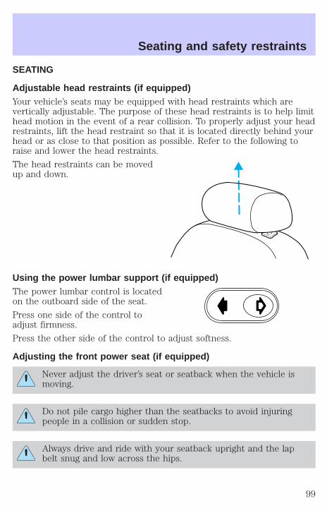
SEATING
Adjustable head restraints (if equipped)Your vehicle’s seats may be equipped with head restraints which arevertically adjustable. The purpose of these head restraints is to help limithead motion in the event of a rear collision. To properly adjust your headrestraints, lift the head restraint so that it is located directly behind yourhead or as close to that position as possible. Refer to the following toraise and lower the head restraints.
The head restraints can be movedup and down.
Using the power lumbar support (if equipped)The power lumbar control is locatedon the outboard side of the seat.
Press one side of the control toadjust firmness.
Press the other side of the control to adjust softness.
Adjusting the front power seat (if equipped)
Never adjust the driver’s seat or seatback when the vehicle ismoving.
Do not pile cargo higher than the seatbacks to avoid injuringpeople in a collision or sudden stop.
Always drive and ride with your seatback upright and the lapbelt snug and low across the hips.
Seating and safety restraints
99
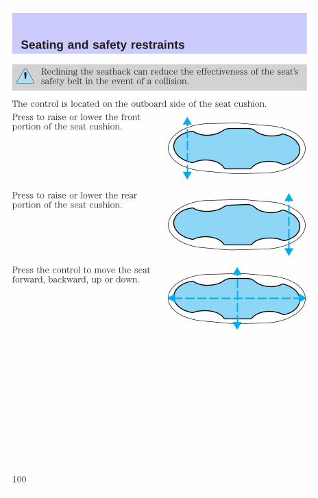
Reclining the seatback can reduce the effectiveness of the seat’ssafety belt in the event of a collision.
The control is located on the outboard side of the seat cushion.
Press to raise or lower the frontportion of the seat cushion.
Press to raise or lower the rearportion of the seat cushion.
Press the control to move the seatforward, backward, up or down.
Seating and safety restraints
100
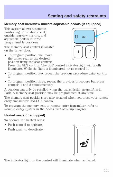
Memory seats/rearview mirrors/adjustable pedals (if equipped)This system allows automaticpositioning of the driver seat,outside rearview mirrors, andadjustable pedals to threeprogrammable positions.
The memory seat control is locatedon the driver door.
• To program position one, movethe driver seat to the desiredposition using the seat controls.Press the SET control. The SET control indicator light will brieflyilluminate. While the light is illuminated, press control 1.
• To program position two, repeat the previous procedure using control2.
• To program position three, repeat the previous procedure but presscontrols 1 and 2 simultaneously.
A position can only be recalled when the transmission gearshift is inPark. A memory seat position may be programmed at any time.
The memory seat positions are also recalled when you press your remoteentry transmitter UNLOCK control.
To program the memory seat to remote entry transmitter, refer toRemote entry system in the Locks and security chapter.
Heated seats (if equipped)To operate the heated seats:
• Push control to activate.
• Push again to deactivate.
The indicator light on the control will illuminate when activated.
SET
1 2
Seating and safety restraints
101
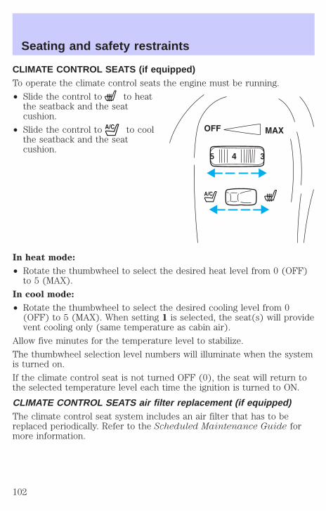
CLIMATE CONTROL SEATS (if equipped)To operate the climate control seats the engine must be running.
• Slide the control to to heatthe seatback and the seatcushion.
• Slide the control to to coolthe seatback and the seatcushion.
In heat mode:
• Rotate the thumbwheel to select the desired heat level from 0 (OFF)to 5 (MAX).
In cool mode:
• Rotate the thumbwheel to select the desired cooling level from 0(OFF) to 5 (MAX). When setting 1 is selected, the seat(s) will providevent cooling only (same temperature as cabin air).
Allow five minutes for the temperature level to stabilize.
The thumbwheel selection level numbers will illuminate when the systemis turned on.
If the climate control seat is not turned OFF (0), the seat will return tothe selected temperature level each time the ignition is turned to ON.
CLIMATE CONTROL SEATS air filter replacement (if equipped)The climate control seat system includes an air filter that has to bereplaced periodically. Refer to the Scheduled Maintenance Guide formore information.
5 3
Seating and safety restraints
102
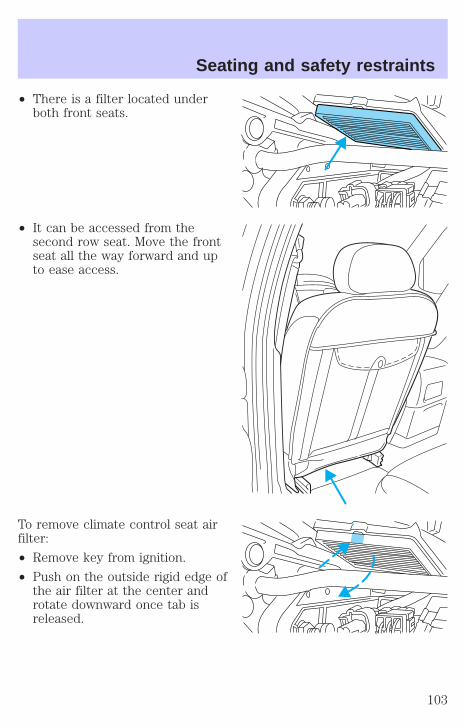
• There is a filter located underboth front seats.
• It can be accessed from thesecond row seat. Move the frontseat all the way forward and upto ease access.
To remove climate control seat airfilter:
• Remove key from ignition.
• Push on the outside rigid edge ofthe air filter at the center androtate downward once tab isreleased.
����
����
Seating and safety restraints
103
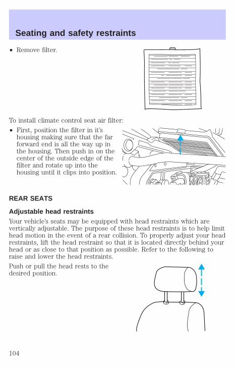
• Remove filter.
To install climate control seat air filter:
• First, position the filter in it’shousing making sure that the farforward end is all the way up inthe housing. Then push in on thecenter of the outside edge of thefilter and rotate up into thehousing until it clips into position.
REAR SEATS
Adjustable head restraintsYour vehicle’s seats may be equipped with head restraints which arevertically adjustable. The purpose of these head restraints is to help limithead motion in the event of a rear collision. To properly adjust your headrestraints, lift the head restraint so that it is located directly behind yourhead or as close to that position as possible. Refer to the following toraise and lower the head restraints.
Push or pull the head rests to thedesired position.
Seating and safety restraints
104
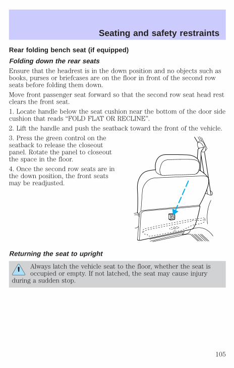
Rear folding bench seat (if equipped)
Folding down the rear seatsEnsure that the headrest is in the down position and no objects such asbooks, purses or briefcases are on the floor in front of the second rowseats before folding them down.
Move front passenger seat forward so that the second row seat head restclears the front seat.
1. Locate handle below the seat cushion near the bottom of the door sidecushion that reads “FOLD FLAT OR RECLINE”.
2. Lift the handle and push the seatback toward the front of the vehicle.
3. Press the green control on theseatback to release the closeoutpanel. Rotate the panel to closeoutthe space in the floor.
4. Once the second row seats are inthe down position, the front seatsmay be readjusted.
Returning the seat to upright
Always latch the vehicle seat to the floor, whether the seat isoccupied or empty. If not latched, the seat may cause injury
during a sudden stop.
Seating and safety restraints
105
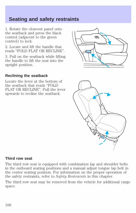
1. Rotate the closeout panel ontothe seatback and press the blackcontrol (adjacent to the greencontrol) to lock.
2. Locate and lift the handle thatreads “FOLD FLAT OR RECLINE”.
3. Pull on the seatback while liftingthe handle to lift the seat into theupright position.
Reclining the seatbackLocate the lever at the bottom ofthe seatback that reads “FOLDFLAT OR RECLINE”. Pull the leverupwards to recline the seatback.
Third row seatThe third row seat is equipped with combination lap and shoulder beltsin the outboard seating positions and a manual adjust tongue lap belt inthe center seating position. For information on the proper operation ofthe safety restraints, refer to Safety Restraints in this chapter.
The third row seat may be removed from the vehicle for additional cargospace.
Seating and safety restraints
106
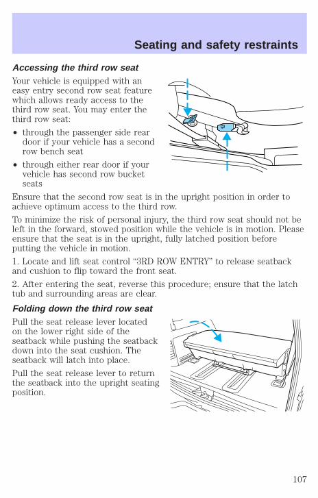
Accessing the third row seatYour vehicle is equipped with aneasy entry second row seat featurewhich allows ready access to thethird row seat. You may enter thethird row seat:
• through the passenger side reardoor if your vehicle has a secondrow bench seat
• through either rear door if yourvehicle has second row bucketseats
Ensure that the second row seat is in the upright position in order toachieve optimum access to the third row.
To minimize the risk of personal injury, the third row seat should not beleft in the forward, stowed position while the vehicle is in motion. Pleaseensure that the seat is in the upright, fully latched position beforeputting the vehicle in motion.
1. Locate and lift seat control “3RD ROW ENTRY” to release seatbackand cushion to flip toward the front seat.
2. After entering the seat, reverse this procedure; ensure that the latchtub and surrounding areas are clear.
Folding down the third row seatPull the seat release lever locatedon the lower right side of theseatback while pushing the seatbackdown into the seat cushion. Theseatback will latch into place.
Pull the seat release lever to returnthe seatback into the upright seatingposition.
Seating and safety restraints
107
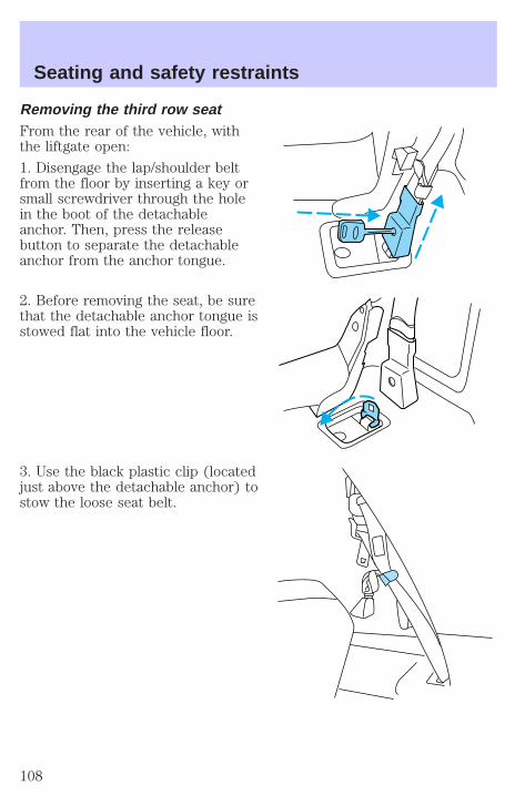
Removing the third row seatFrom the rear of the vehicle, withthe liftgate open:
1. Disengage the lap/shoulder beltfrom the floor by inserting a key orsmall screwdriver through the holein the boot of the detachableanchor. Then, press the releasebutton to separate the detachableanchor from the anchor tongue.
2. Before removing the seat, be surethat the detachable anchor tongue isstowed flat into the vehicle floor.
3. Use the black plastic clip (locatedjust above the detachable anchor) tostow the loose seat belt.
Seating and safety restraints
108
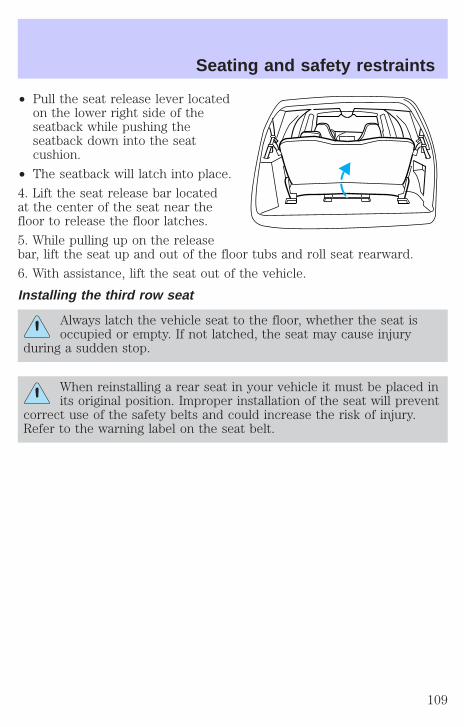
• Pull the seat release lever locatedon the lower right side of theseatback while pushing theseatback down into the seatcushion.
• The seatback will latch into place.
4. Lift the seat release bar locatedat the center of the seat near thefloor to release the floor latches.
5. While pulling up on the releasebar, lift the seat up and out of the floor tubs and roll seat rearward.
6. With assistance, lift the seat out of the vehicle.
Installing the third row seat
Always latch the vehicle seat to the floor, whether the seat isoccupied or empty. If not latched, the seat may cause injury
during a sudden stop.
When reinstalling a rear seat in your vehicle it must be placed inits original position. Improper installation of the seat will prevent
correct use of the safety belts and could increase the risk of injury.Refer to the warning label on the seat belt.
Seating and safety restraints
109

Before installing your third row seat,ensure that the detachable anchortongues are stowed into the floorand the loose belts are stored out ofthe way. For proper latching, ensurethat the floor tubs are clear ofdebris.
From the rear of the vehicle, withthe liftgate open:
1. With assistance, lift the seat into the rear of the vehicle and positionfront rollers onto the track. By rolling the seat forward, guide the seatpositioners over the front pins of the floor tubs.
2. Guide the positioners around each pin and lower the seat.
• When the rear of the seat is 10–13 cm (4–5 in) above the rear pins,let the seat drop. This will ensure that the seat will properly latch intothe floor.
3. Locate the seat belt anchor tongue in the plastic housing on the floor.
4. Disconnect the detachable anchor from its stowage location andconnect it to the anchor tongue (making sure that the label on thedetachable anchor is pointing toward the outside of the vehicle (leftside) and that the belts are not twisted or jammed).
NOTE:Improper installation of the seat belt anchor will prevent correctuse of the safety belt and could increase the risk or injury.
5. Insert the seat detachable anchor into detachable anchor tongue untilyou hear a “click” and feel the latch engage.
6. Push up on the seat to verify that it is latched into the floor.
7. Verify that the safety belts can move freely on either side of the seat.
Seating and safety restraints
110
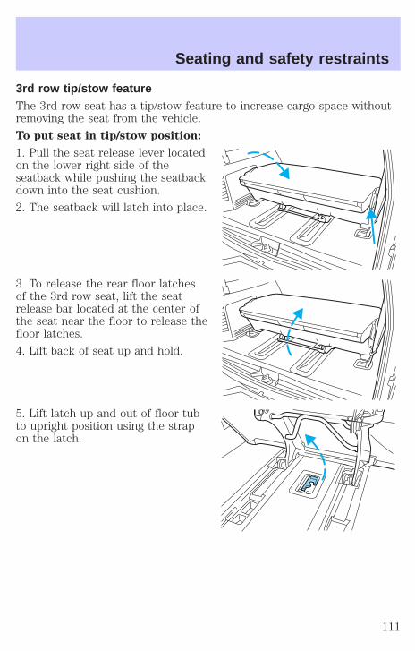
3rd row tip/stow featureThe 3rd row seat has a tip/stow feature to increase cargo space withoutremoving the seat from the vehicle.
To put seat in tip/stow position:
1. Pull the seat release lever locatedon the lower right side of theseatback while pushing the seatbackdown into the seat cushion.
2. The seatback will latch into place.
3. To release the rear floor latchesof the 3rd row seat, lift the seatrelease bar located at the center ofthe seat near the floor to release thefloor latches.
4. Lift back of seat up and hold.
5. Lift latch up and out of floor tubto upright position using the strapon the latch.
Seating and safety restraints
111

6. Pull down support bar and pushinto floor latch.
To return seat to seating position:
1. Hold seat and pull support bar from floor latch.
2. Rotate support bar up under seat.
3. Rotate floor latch down into floor tub.
4. Lower the seat. When the rear of the seat is 10–13 cm (4–5 in) abovethe rear pins, let the seat drop. This will ensure that the seat willproperly latch into the floor.
SAFETY RESTRAINTS
Safety restraints precautions
Always drive and ride with your seatback upright and the lapbelt snug and low across the hips.
To reduce the risk of injury, make sure children sit where theycan be properly restrained.
Never let a passenger hold a child on his or her lap while thevehicle is moving. The passenger cannot protect the child from
injury in a collision.
All occupants of the vehicle, including the driver, should alwaysproperly wear their safety belts, even when an air bag (SRS) is
provided.
Seating and safety restraints
112
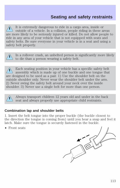
It is extremely dangerous to ride in a cargo area, inside oroutside of a vehicle. In a collision, people riding in these areas
are more likely to be seriously injured or killed. Do not allow people toride in any area of your vehicle that is not equipped with seats andsafety belts. Be sure everyone in your vehicle is in a seat and using asafety belt properly.
In a rollover crash, an unbelted person is significantly more likelyto die than a person wearing a safety belt.
Each seating position in your vehicle has a specific safety beltassembly which is made up of one buckle and one tongue that
are designed to be used as a pair. 1) Use the shoulder belt on theoutside shoulder only. Never wear the shoulder belt under the arm.2) Never swing the safety belt around your neck over the insideshoulder. 3) Never use a single belt for more than one person.
Always transport children 12 years old and under in the backseat and always properly use appropriate child restraints.
Combination lap and shoulder belts1. Insert the belt tongue into the proper buckle (the buckle closest tothe direction the tongue is coming from) until you hear a snap and feel itlatch. Make sure the tongue is securely fastened in the buckle.
• Front seats
Seating and safety restraints
113
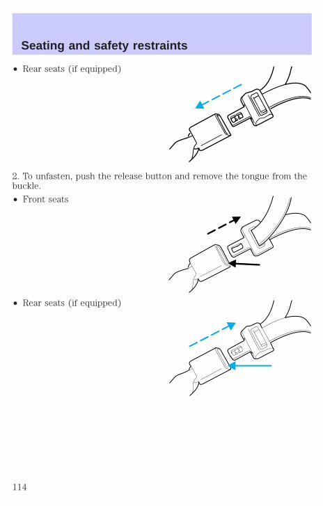
• Rear seats (if equipped)
2. To unfasten, push the release button and remove the tongue from thebuckle.
• Front seats
• Rear seats (if equipped)
Seating and safety restraints
114
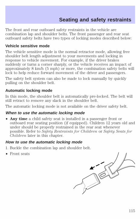
The front and rear outboard safety restraints in the vehicle arecombination lap and shoulder belts. The front passenger and rear seatoutboard safety belts have two types of locking modes described below:
Vehicle sensitive modeThe vehicle sensitive mode is the normal retractor mode, allowing freeshoulder belt length adjustment to your movements and locking inresponse to vehicle movement. For example, if the driver brakessuddenly or turns a corner sharply, or the vehicle receives an impact ofapproximately 8 km/h (5 mph) or more, the combination safety belts willlock to help reduce forward movement of the driver and passengers.
The safety belt system can also be made to lock manually by quicklypulling on the shoulder belt.
Automatic locking modeIn this mode, the shoulder belt is automatically pre-locked. The belt willstill retract to remove any slack in the shoulder belt.
The automatic locking mode is not available on the driver safety belt.
When to use the automatic locking mode• Any time a child safety seat is installed in a passenger front or
outboard rear seating position (if equipped). Children 12 years old andunder should be properly restrained in the rear seat wheneverpossible. Refer to Safety Restraints for Children or Safety Seats forChildren later in this chapter.
How to use the automatic locking mode1. Buckle the combination lap and shoulder belt.
• Front seats
Seating and safety restraints
115
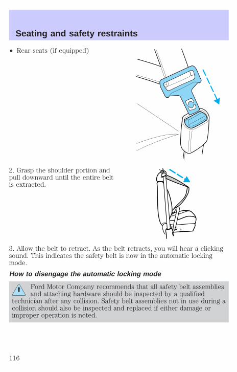
• Rear seats (if equipped)
2. Grasp the shoulder portion andpull downward until the entire beltis extracted.
3. Allow the belt to retract. As the belt retracts, you will hear a clickingsound. This indicates the safety belt is now in the automatic lockingmode.
How to disengage the automatic locking mode
Ford Motor Company recommends that all safety belt assembliesand attaching hardware should be inspected by a qualified
technician after any collision. Safety belt assemblies not in use during acollision should also be inspected and replaced if either damage orimproper operation is noted.
Seating and safety restraints
116
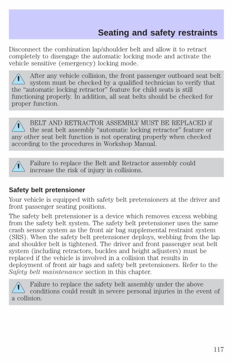
Disconnect the combination lap/shoulder belt and allow it to retractcompletely to disengage the automatic locking mode and activate thevehicle sensitive (emergency) locking mode.
After any vehicle collision, the front passenger outboard seat beltsystem must be checked by a qualified technician to verify that
the “automatic locking retractor” feature for child seats is stillfunctioning properly. In addition, all seat belts should be checked forproper function.
BELT AND RETRACTOR ASSEMBLY MUST BE REPLACED ifthe seat belt assembly “automatic locking retractor” feature or
any other seat belt function is not operating properly when checkedaccording to the procedures in Workshop Manual.
Failure to replace the Belt and Retractor assembly couldincrease the risk of injury in collisions.
Safety belt pretensionerYour vehicle is equipped with safety belt pretensioners at the driver andfront passenger seating positions.
The safety belt pretensioner is a device which removes excess webbingfrom the safety belt system. The safety belt pretensioner uses the samecrash sensor system as the front air bag supplemental restraint system(SRS). When the safety belt pretensioner deploys, webbing from the lapand shoulder belt is tightened. The driver and front passenger seat beltsystem (including retractors, buckles and height adjusters) must bereplaced if the vehicle is involved in a collision that results indeployment of front air bags and safety belt pretensioners. Refer to theSafety belt maintenance section in this chapter.
Failure to replace the safety belt assembly under the aboveconditions could result in severe personal injuries in the event of
a collision.
Seating and safety restraints
117
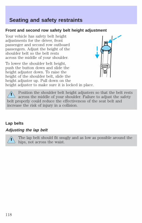
Front and second row safety belt height adjustmentYour vehicle has safety belt heightadjustments for the driver, frontpassenger and second row outboardpassengers. Adjust the height of theshoulder belt so the belt restsacross the middle of your shoulder.
To lower the shoulder belt height,push the button down and slide theheight adjuster down. To raise theheight of the shoulder belt, slide theheight adjuster up. Pull down on theheight adjuster to make sure it is locked in place.
Position the shoulder belt height adjusters so that the belt restsacross the middle of your shoulder. Failure to adjust the safety
belt properly could reduce the effectiveness of the seat belt andincrease the risk of injury in a collision.
Lap belts
Adjusting the lap belt
The lap belt should fit snugly and as low as possible around thehips, not across the waist.
Seating and safety restraints
118
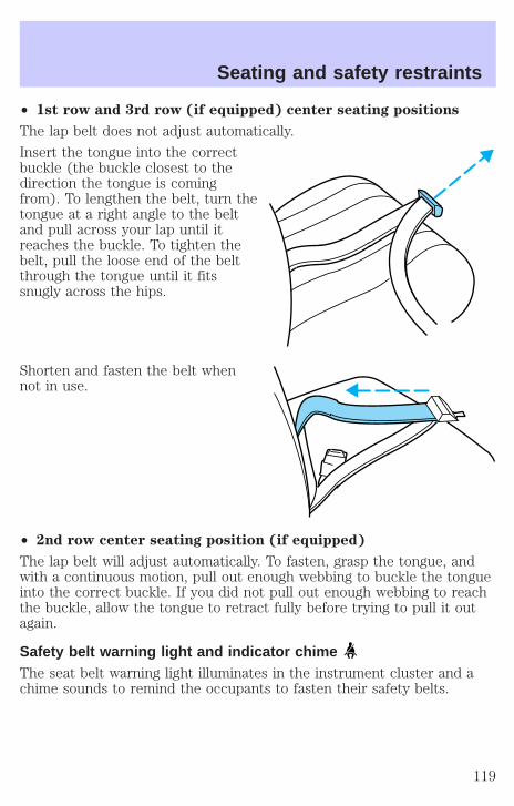
• 1st row and 3rd row (if equipped) center seating positions
The lap belt does not adjust automatically.
Insert the tongue into the correctbuckle (the buckle closest to thedirection the tongue is comingfrom). To lengthen the belt, turn thetongue at a right angle to the beltand pull across your lap until itreaches the buckle. To tighten thebelt, pull the loose end of the beltthrough the tongue until it fitssnugly across the hips.
Shorten and fasten the belt whennot in use.
• 2nd row center seating position (if equipped)
The lap belt will adjust automatically. To fasten, grasp the tongue, andwith a continuous motion, pull out enough webbing to buckle the tongueinto the correct buckle. If you did not pull out enough webbing to reachthe buckle, allow the tongue to retract fully before trying to pull it outagain.
Safety belt warning light and indicator chimeThe seat belt warning light illuminates in the instrument cluster and achime sounds to remind the occupants to fasten their safety belts.
Seating and safety restraints
119
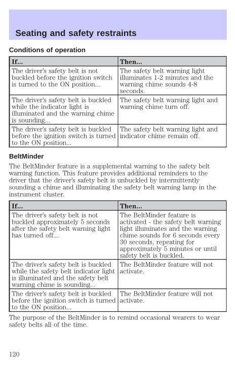
Conditions of operation
If... Then...
The driver’s safety belt is notbuckled before the ignition switchis turned to the ON position...
The safety belt warning lightilluminates 1-2 minutes and thewarning chime sounds 4-8seconds.
The driver’s safety belt is buckledwhile the indicator light isilluminated and the warning chimeis sounding...
The safety belt warning light andwarning chime turn off.
The driver’s safety belt is buckledbefore the ignition switch is turnedto the ON position...
The safety belt warning light andindicator chime remain off.
BeltMinderThe BeltMinder feature is a supplemental warning to the safety beltwarning function. This feature provides additional reminders to thedriver that the driver’s safety belt is unbuckled by intermittentlysounding a chime and illuminating the safety belt warning lamp in theinstrument cluster.
If... Then...
The driver’s safety belt is notbuckled approximately 5 secondsafter the safety belt warning lighthas turned off...
The BeltMinder feature isactivated - the safety belt warninglight illuminates and the warningchime sounds for 6 seconds every30 seconds, repeating forapproximately 5 minutes or untilsafety belt is buckled.
The driver’s safety belt is buckledwhile the safety belt indicator lightis illuminated and the safety beltwarning chime is sounding...
The BeltMinder feature will notactivate.
The driver’s safety belt is buckledbefore the ignition switch is turnedto the ON position...
The BeltMinder feature will notactivate.
The purpose of the BeltMinder is to remind occasional wearers to wearsafety belts all of the time.
Seating and safety restraints
120
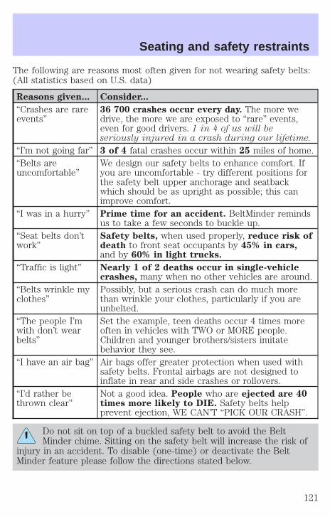
The following are reasons most often given for not wearing safety belts:(All statistics based on U.S. data)
Reasons given... Consider...
“Crashes are rareevents”
36 700 crashes occur every day. The more wedrive, the more we are exposed to “rare” events,even for good drivers. 1 in 4 of us will beseriously injured in a crash during our lifetime.
“I’m not going far” 3 of 4 fatal crashes occur within 25 miles of home.“Belts areuncomfortable”
We design our safety belts to enhance comfort. Ifyou are uncomfortable - try different positions forthe safety belt upper anchorage and seatbackwhich should be as upright as possible; this canimprove comfort.
“I was in a hurry” Prime time for an accident. BeltMinder remindsus to take a few seconds to buckle up.
“Seat belts don’twork”
Safety belts, when used properly, reduce risk ofdeath to front seat occupants by 45% in cars,and by 60% in light trucks.
“Traffic is light” Nearly 1 of 2 deaths occur in single-vehiclecrashes, many when no other vehicles are around.
“Belts wrinkle myclothes”
Possibly, but a serious crash can do much morethan wrinkle your clothes, particularly if you areunbelted.
“The people I’mwith don’t wearbelts”
Set the example, teen deaths occur 4 times moreoften in vehicles with TWO or MORE people.Children and younger brothers/sisters imitatebehavior they see.
“I have an air bag” Air bags offer greater protection when used withsafety belts. Frontal airbags are not designed toinflate in rear and side crashes or rollovers.
“I’d rather bethrown clear”
Not a good idea. People who are ejected are 40times more likely to DIE. Safety belts helpprevent ejection, WE CAN’T “PICK OUR CRASH”.
Do not sit on top of a buckled safety belt to avoid the BeltMinder chime. Sitting on the safety belt will increase the risk of
injury in an accident. To disable (one-time) or deactivate the BeltMinder feature please follow the directions stated below.
Seating and safety restraints
121

One time disableAny time the safety belt is buckled and then unbuckled during anignition ON cycle, BeltMinder will be disabled for that ignition cycle only.
Deactivating/activating the BeltMinder featureRead steps 1 - 9 thoroughly before proceeding with thedeactivation/activation programming procedure.
The BeltMinder feature can be deactivated/activated by performing thefollowing procedure:
Before following the procedure, make sure that:
• the parking brake is set
• the gearshift is in P (Park) (automatic transmission)
• the ignition switch is in the OFF position
• all vehicle doors are closed
• the driver’s safety belt is unbuckled
• the parklamps/headlamps are in OFF position (If vehicle is equippedwith Autolamps, this will not affect the procedure.)
To reduce the risk of injury, do not deactivate/activate the BeltMinder feature while driving the vehicle.
1. Turn the ignition switch to the RUN (or ON) position. (DO NOTSTART THE ENGINE)
2. Wait until the safety belt warning light turns off. (Approximately 1–2minutes)
• Steps 3–5 must be completed within 60 seconds or the procedure willhave to be repeated.
3. Buckle then unbuckle the safety belt three times, ending with thesafety belt unbuckled. This can be done before or during BeltMinderwarning activation.
4. Turn on the parklamps/headlamps, turn off the parklamps/headlamps.
5. Buckle then unbuckle the safety belt three times, ending with thesafety belt unbuckled.
• After step 5 the safety belt warning light will be turned on for threeseconds.
Seating and safety restraints
122

6. Within seven seconds of the safety belt warning light turning off,buckle then unbuckle the safety belt.
• This will disable BeltMinder if it is currently enabled, or enableBeltMinder if it is currently disabled.
7. Confirmation of disabling BeltMinder is provided by flashing the safetybelt warning light four times per second for three seconds.
8. Confirmation of enabling BeltMinder is provided by flashing the safetybelt warning light four times per second for three seconds, followed bythree seconds with the safety belt warning light off, then followed byflashing the safety belt warning light four times per second for threeseconds again.
9. After receiving confirmation, the deactivation/activation procedure iscomplete.
Safety belt extension assemblyIf the safety belt is too short when fully extended, there is a 20 cm (8inch) safety belt extension assembly that can be added (part number611C22). This assembly can be obtained from your dealer at no cost.
Use only extensions manufactured by the same supplier as the safetybelt. Manufacturer identification is located at the end of the webbing onthe label. Also, use the safety belt extension only if the safety belt is tooshort for you when fully extended. Do not use extensions to change thefit of the shoulder belt across the torso.
Safety belt maintenanceInspect the safety belt systems periodically to make sure they workproperly and are not damaged. Inspect the safety belts to make surethere are no nicks, tears or cuts. Replace if necessary. All safety beltassemblies, including retractors, buckles, front seat belt buckleassemblies, buckle support assemblies (slide bar-if equipped), shoulderbelt height adjusters (if equipped), shoulder belt guide on seatback (ifequipped), child safety seat tether bracket assemblies (if equipped),LATCH child seat tether anchors and lower anchors (if equipped), andattaching hardware, should be inspected after a collision. Ford MotorCompany recommends that all safety belt assemblies used in vehiclesinvolved in a collision be replaced. However, if the collision was minorand a qualified technician finds that the belts do not show damage andcontinue to operate properly, they do not need to be replaced. Safetybelt assemblies not in use during a collision should also be inspected andreplaced if either damage or improper operation is noted.
Seating and safety restraints
123
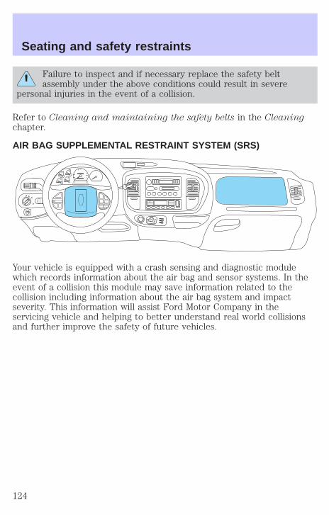
Failure to inspect and if necessary replace the safety beltassembly under the above conditions could result in severe
personal injuries in the event of a collision.
Refer to Cleaning and maintaining the safety belts in the Cleaningchapter.
AIR BAG SUPPLEMENTAL RESTRAINT SYSTEM (SRS)
Your vehicle is equipped with a crash sensing and diagnostic modulewhich records information about the air bag and sensor systems. In theevent of a collision this module may save information related to thecollision including information about the air bag system and impactseverity. This information will assist Ford Motor Company in theservicing vehicle and helping to better understand real world collisionsand further improve the safety of future vehicles.
Seating and safety restraints
124
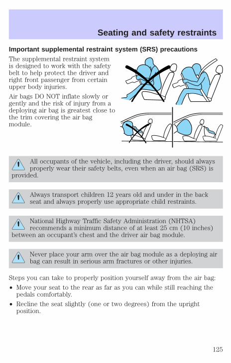
Important supplemental restraint system (SRS) precautionsThe supplemental restraint systemis designed to work with the safetybelt to help protect the driver andright front passenger from certainupper body injuries.
Air bags DO NOT inflate slowly orgently and the risk of injury from adeploying air bag is greatest close tothe trim covering the air bagmodule.
All occupants of the vehicle, including the driver, should alwaysproperly wear their safety belts, even when an air bag (SRS) is
provided.
Always transport children 12 years old and under in the backseat and always properly use appropriate child restraints.
National Highway Traffic Safety Administration (NHTSA)recommends a minimum distance of at least 25 cm (10 inches)
between an occupant’s chest and the driver air bag module.
Never place your arm over the air bag module as a deploying airbag can result in serious arm fractures or other injuries.
Steps you can take to properly position yourself away from the air bag:
• Move your seat to the rear as far as you can while still reaching thepedals comfortably.
• Recline the seat slightly (one or two degrees) from the uprightposition.
Seating and safety restraints
125
Do not put anything on or over the air bag module. Placingobjects on or over the air bag inflation area may cause those
objects to be propelled by the air bag into your face and torso causingserious injury.
Do not attempt to service, repair, or modify the air bagsupplemental restraint systems or its fuses. See your Ford or
Lincoln Mercury dealer.
Modifications to the front end of the vehicle, including frame,bumper, front end body structure and tow hooks may affect the
performance of the air bag sensors increasing the risk of injury. Do notmodify the front end of the vehicle.
Additional equipment may affect the performance of the air bagsensors increasing the risk of injury. Please refer to the Body
Builders Layout Book for instructions about the appropriate installationof additional equipment.
Seating and safety restraints
126
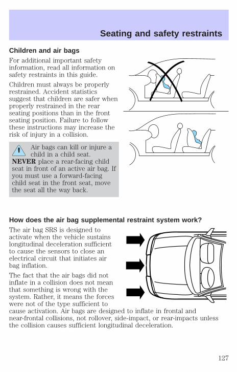
Children and air bagsFor additional important safetyinformation, read all information onsafety restraints in this guide.
Children must always be properlyrestrained. Accident statisticssuggest that children are safer whenproperly restrained in the rearseating positions than in the frontseating position. Failure to followthese instructions may increase therisk of injury in a collision.
Air bags can kill or injure achild in a child seat.
NEVER place a rear-facing childseat in front of an active air bag. Ifyou must use a forward-facingchild seat in the front seat, movethe seat all the way back.
How does the air bag supplemental restraint system work?The air bag SRS is designed toactivate when the vehicle sustainslongitudinal deceleration sufficientto cause the sensors to close anelectrical circuit that initiates airbag inflation.
The fact that the air bags did notinflate in a collision does not meanthat something is wrong with thesystem. Rather, it means the forceswere not of the type sufficient tocause activation. Air bags are designed to inflate in frontal andnear-frontal collisions, not rollover, side-impact, or rear-impacts unlessthe collision causes sufficient longitudinal deceleration.
Seating and safety restraints
127
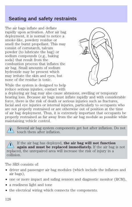
The air bags inflate and deflaterapidly upon activation. After air bagdeployment, it is normal to notice asmoke-like, powdery residue orsmell the burnt propellant. This mayconsist of cornstarch, talcumpowder (to lubricate the bag) orsodium compounds (e.g., bakingsoda) that result from thecombustion process that inflates theair bag. Small amounts of sodiumhydroxide may be present whichmay irritate the skin and eyes, butnone of the residue is toxic.
While the system is designed to helpreduce serious injuries, contact witha deploying air bag may also cause abrasions, swelling or temporaryhearing loss. Because air bags must inflate rapidly and with considerableforce, there is the risk of death or serious injuries such as fractures,facial and eye injuries or internal injuries, particularly to occupants whoare not properly restrained or are otherwise out of position at the timeof air bag deployment. Thus, it is extremely important that occupants beproperly restrained as far away from the air bag module as possible whilemaintaining vehicle control.
Several air bag system components get hot after inflation. Do nottouch them after inflation.
If the air bag has deployed, the air bag will not functionagain and must be replaced immediately. If the air bag is not
replaced, the unrepaired area will increase the risk of injury in acollision.
The SRS consists of:
• driver and passenger air bag modules (which include the inflators andair bags),
• one or more impact and safing sensors and diagnostic monitor (RCM),
• a readiness light and tone
• the electrical wiring which connects the components.
Seating and safety restraints
128
The RCM (restraints control module) monitors its own internal circuitsand the supplemental air bag electrical system warning (including theimpact sensors, the system wiring, the air bag system readiness light, theair bag back up power and the air bag ignitors).
Determining if the system is operationalThe SRS uses a readiness light in the instrument cluster or a tone toindicate the condition of the system. Refer to Air bag readiness sectionin the Instrument cluster chapter. Routine maintenance of the air bag isnot required.
A difficulty with the system is indicated by one or more of the following:
• The readiness light will eitherflash or stay lit.
• The readiness light will notilluminate immediately after ignition is turned on.
• A series of five beeps will be heard. The tone pattern will repeatperiodically until the problem and/or light are repaired.
If any of these things happen, even intermittently, have the SRS servicedat your dealership or by a qualified technician immediately. Unlessserviced, the system may not function properly in the event of acollision.
Side air bag system (if equipped)
Do not place objects or mount equipment on or near the air bagcover on the side of the seatbacks of the front seats or in front
seat areas that may come into contact with a deploying air bag. Failureto follow these instructions may increase the risk of personal injury inthe event of a collision.
Do not use accessory seat covers. The use of accessory seatcovers may prevent the deployment of the side air bags and
increase the risk of injury in an accident.
Do not lean your head on the door. The side air bag could injureyou as it deploys from the side of the seatback.
Seating and safety restraints
129
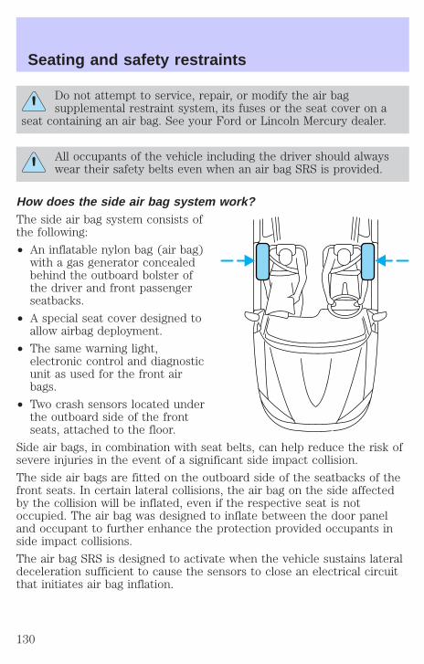
Do not attempt to service, repair, or modify the air bagsupplemental restraint system, its fuses or the seat cover on a
seat containing an air bag. See your Ford or Lincoln Mercury dealer.
All occupants of the vehicle including the driver should alwayswear their safety belts even when an air bag SRS is provided.
How does the side air bag system work?The side air bag system consists ofthe following:
• An inflatable nylon bag (air bag)with a gas generator concealedbehind the outboard bolster ofthe driver and front passengerseatbacks.
• A special seat cover designed toallow airbag deployment.
• The same warning light,electronic control and diagnosticunit as used for the front airbags.
• Two crash sensors located underthe outboard side of the frontseats, attached to the floor.
Side air bags, in combination with seat belts, can help reduce the risk ofsevere injuries in the event of a significant side impact collision.
The side air bags are fitted on the outboard side of the seatbacks of thefront seats. In certain lateral collisions, the air bag on the side affectedby the collision will be inflated, even if the respective seat is notoccupied. The air bag was designed to inflate between the door paneland occupant to further enhance the protection provided occupants inside impact collisions.
The air bag SRS is designed to activate when the vehicle sustains lateraldeceleration sufficient to cause the sensors to close an electrical circuitthat initiates air bag inflation.
Seating and safety restraints
130
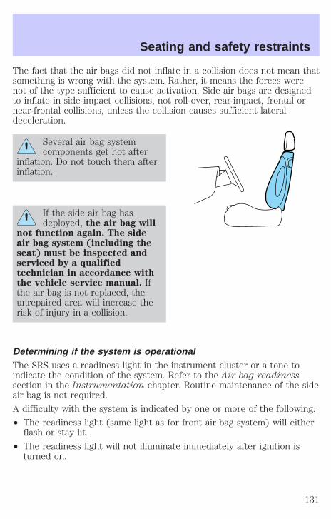
The fact that the air bags did not inflate in a collision does not mean thatsomething is wrong with the system. Rather, it means the forces werenot of the type sufficient to cause activation. Side air bags are designedto inflate in side-impact collisions, not roll-over, rear-impact, frontal ornear-frontal collisions, unless the collision causes sufficient lateraldeceleration.
Several air bag systemcomponents get hot after
inflation. Do not touch them afterinflation.
If the side air bag hasdeployed, the air bag will
not function again. The sideair bag system (including theseat) must be inspected andserviced by a qualifiedtechnician in accordance withthe vehicle service manual. Ifthe air bag is not replaced, theunrepaired area will increase therisk of injury in a collision.
Determining if the system is operationalThe SRS uses a readiness light in the instrument cluster or a tone toindicate the condition of the system. Refer to the Air bag readinesssection in the Instrumentation chapter. Routine maintenance of the sideair bag is not required.
A difficulty with the system is indicated by one or more of the following:
• The readiness light (same light as for front air bag system) will eitherflash or stay lit.
• The readiness light will not illuminate immediately after ignition isturned on.
Seating and safety restraints
131

• A series of five beeps will be heard. The tone pattern will repeatperiodically until the problem and light are repaired.
If any of these things happen, even intermittently, have the SRS servicedat your dealership or by a qualified technician immediately. Unlessserviced, the system may not function properly in the event of acollision.
Disposal of air bags and air bag equipped vehicles(including pretensioners)For disposal of air bags or air bag equipped vehicles, see your localdealership or qualified technician. Air bags MUST BE disposed of byqualified personnel.
SAFETY RESTRAINTS FOR CHILDRENSee the following sections for directions on how to properly use safetyrestraints for children. Also see Air bag supplemental restraint system(SRS) in this chapter for special instructions about using air bags.
Important child restraint precautionsYou are required by law to use safety restraints for children in the U.S.and Canada. If small children ride in your vehicle (generally children whoare four years old or younger and who weigh 18 kg [40 lbs] or less), youmust put them in safety seats made especially for children. Check yourlocal and state or provincial laws for specific requirements regarding thesafety of children in your vehicle.
Never let a passenger hold a child on his or her lap while thevehicle is moving. The passenger cannot protect the child from
injury in a collision.
Always follow the instructions and warnings that come with any infant orchild restraint you might use.
When possible, always place children under age 12 in the rear seat ofyour vehicle. Accident statistics suggest that children are safer whenproperly restrained in the rear seating positions than in the front seatingposition.
Children and safety beltsIf the child is the proper size, restrain the child in a safety seat.
Seating and safety restraints
132
Children who are too large for child safety seats (as specified by yourchild safety seat manufacturer) should always wear safety belts.
Follow all the important safety restraint and air bag precautions thatapply to adult passengers in your vehicle.
If the shoulder belt portion of a combination lap and shoulder belt canbe positioned so it does not cross or rest in front of the child’s face orneck, the child should wear the lap and shoulder belt. Moving the childcloser to the center of the vehicle may help provide a good shoulder beltfit.
Do not leave children, unreliable adults, or pets unattended inyour vehicle.
To improve the fit of lap and shoulder belts on children who haveoutgrown child safety seats, Ford recommends use of a belt-positioningbooster seat that is labelled as conforming to all applicable Federal motorvehicle safety standards. Belt-positioning booster seats raise the childand provide a shorter, firmer seating cushion that encourages saferseating posture and better fit of lap and shoulder belts on the child.
A belt-positioning booster seat should be used if the shoulder belt restsin front of the child’s face or neck, or if the lap belt does not fit snuglyon both thighs, or if the thighs are too short to let the child sit all theway back on the seat cushion when the lower legs hang over the edge ofthe seat cushion. You may wish to discuss the special needs of your childwith your pediatrician.
Seating and safety restraints
133
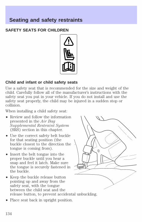
SAFETY SEATS FOR CHILDREN
Child and infant or child safety seatsUse a safety seat that is recommended for the size and weight of thechild. Carefully follow all of the manufacturer’s instructions with thesafety seat you put in your vehicle. If you do not install and use thesafety seat properly, the child may be injured in a sudden stop orcollision.
When installing a child safety seat:
• Review and follow the informationpresented in the Air BagSupplemental Restraint System(SRS) section in this chapter.
• Use the correct safety belt bucklefor that seating position (thebuckle closest to the direction thetongue is coming from).
• Insert the belt tongue into theproper buckle until you hear asnap and feel it latch. Make surethe tongue is securely fastened inthe buckle.
• Keep the buckle release buttonpointing up and away from thesafety seat, with the tonguebetween the child seat and therelease button, to prevent accidental unbuckling.
• Place seat back in upright position.
Seating and safety restraints
134
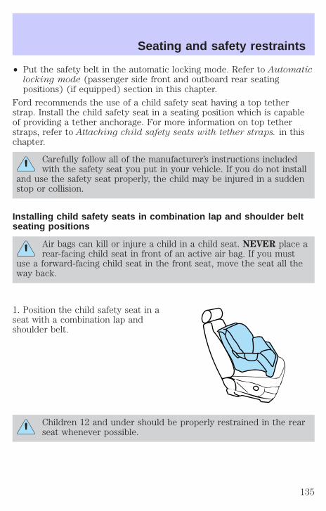
• Put the safety belt in the automatic locking mode. Refer to Automaticlocking mode (passenger side front and outboard rear seatingpositions) (if equipped) section in this chapter.
Ford recommends the use of a child safety seat having a top tetherstrap. Install the child safety seat in a seating position which is capableof providing a tether anchorage. For more information on top tetherstraps, refer to Attaching child safety seats with tether straps. in thischapter.
Carefully follow all of the manufacturer’s instructions includedwith the safety seat you put in your vehicle. If you do not install
and use the safety seat properly, the child may be injured in a suddenstop or collision.
Installing child safety seats in combination lap and shoulder beltseating positions
Air bags can kill or injure a child in a child seat. NEVER place arear-facing child seat in front of an active air bag. If you must
use a forward-facing child seat in the front seat, move the seat all theway back.
1. Position the child safety seat in aseat with a combination lap andshoulder belt.
Children 12 and under should be properly restrained in the rearseat whenever possible.
Seating and safety restraints
135
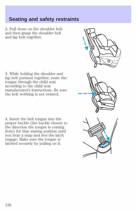
2. Pull down on the shoulder beltand then grasp the shoulder beltand lap belt together.
3. While holding the shoulder andlap belt portions together, route thetongue through the child seataccording to the child seatmanufacturer’s instructions. Be surethe belt webbing is not twisted.
4. Insert the belt tongue into theproper buckle (the buckle closest tothe direction the tongue is comingfrom) for that seating position untilyou hear a snap and feel the latchengage. Make sure the tongue islatched securely by pulling on it.
Seating and safety restraints
136
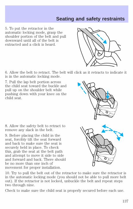
5. To put the retractor in theautomatic locking mode, grasp theshoulder portion of the belt and pulldownward until all of the belt isextracted and a click is heard.
6. Allow the belt to retract. The belt will click as it retracts to indicate itis in the automatic locking mode.
7. Pull the lap belt portion acrossthe child seat toward the buckle andpull up on the shoulder belt whilepushing down with your knee on thechild seat.
8. Allow the safety belt to retract toremove any slack in the belt.
9. Before placing the child in theseat, forcibly tilt the seat forwardand back to make sure the seat issecurely held in place. To checkthis, grab the seat at the belt pathand attempt to move it side to sideand forward and back. There shouldbe no more than one inch ofmovement for proper installation.
10. Try to pull the belt out of the retractor to make sure the retractor isin the automatic locking mode (you should not be able to pull more beltout). If the retractor is not locked, unbuckle the belt and repeat stepstwo through nine.
Check to make sure the child seat is properly secured before each use.
Seating and safety restraints
137
Installing child safety seat in the second row center seatingposition with an automatic locking retractor1. Place the child safety seat in the center seating position.
2. In a continuous motion, pull out enough webbing from the retractor toroute the tongue through the child seat.
3. While holding the webbing to prevent it from retracting, route thewebbing through the child seat according to the child seatmanufacturer’s instructions. Be sure the belt webbing is not twisted.
4. Insert the tongue into the correct buckle for that seating position untilyou hear and feel the buckle engage. Make sure the buckle is latchedsecurely by pulling on the webbing.
5. If you have not pulled out enough webbing to reach, allow thewebbing to fully retract before attempting to pull it out again and repeatsteps 2 through 4.
6. Pull the webbing through the child seat toward the buckle whilepushing down with your knee on the child seat.
7. Allow the safety belt to retract to remove any slack in the belt. It willmake a clicking noise while doing this.
8. Before placing the child in the seat, forcibly tilt the seat forward andback to make sure the seat is securely held in place.
9. Check to make sure the child seat is properly secured before eachuse.
Installing child safety seat in the third row center seating position(if equipped)1. Place the child safety seat in the center seating position.
2. Route the tongue end through the child seat according to the childseat manufacturers instructions. If the tongue will not reach the buckle,lengthen the amount of belt by turning the tongue at a right angle to thebelt and pulling on it until it reaches the buckle. Be sure the beltwebbing is not twisted.
3. Insert the tongue into the correct buckle for that seating position(buckle closest to the direction the tongue is coming from) until youhear and feel the buckle engage. To tighten the belt, pull the loose endof the belt through the tongue until all the slack is removed from thebelt. Make sure the buckle is latched securely by pulling on the webbing.
Seating and safety restraints
138
4. Before placing the child in the seat, forcibly tilt the seat forward andback to make sure the seat is securely held in place.
5. Check to make sure the child seat is properly secured before eachuse.
Attaching safety seats with tether strapsMost forward-facing child safety seats include a tether strap which goesover the back of the set and hooks to an anchoring point. Tether strapsare available as an accessory for many older safety seats. Contact themanufacturer of your child safety seat for information about ordering atether strap.
Tether anchorage hardwareAll second row and one third row seating position have a fabric strapinstalled near the bottom of the rear face of the seatback. These strapshave a loop at the top, and are to be used for child seat tetheranchorages.
A tethered seat can be installed in the front passenger seat. Put thetether strap over the seatback and attach it to an anchor bracket.
Anchor brackets can be bolted to the rear edge of the front passengerseat cushion. The bolt holes are in the bottom of the rear edge of thefront passenger seat cushion frame. The anchor bracket must beinstalled using the instructions provided with the kit.
Tether anchorage hardware kits (part number 613D74) includinginstructions, may be obtained at no charge from any Ford orLincoln/Mercury dealer.
Tighten the anchor according to specifications. Otherwise, thesafety seat may not be properly secured and the child may be
injured in a sudden stop or collision.
Attaching child safety seats with tether strapsMost new forward-facing child safety seats include a tether strap whichgoes over the back of the seat and hooks to an anchoring point. Tetherstraps are available as an accessory for many older safety seats. Contactthe manufacturer of your child seat for information about ordering atether strap.
Seating and safety restraints
139

The rear seats of your vehicle are equipped with built-in tether strapanchors located behind the seats as described below.
The tether anchors in your vehicle are straps on the seatback.
The tether strap anchors in yourvehicle are in the following positions(shown from top view):
Attach the tether strap onlyto the appropriate tether
anchor as shown. The tether strapmay not work properly if attachedsomewhere other than the correcttether anchor.
1. Position the child safety seat onthe seat cushion.
2. Route the child safety seat tetherstrap over the back of the seat.
3. Locate the correct anchor for the selected seating position. (Shownwith the seats folded down.)
Seating and safety restraints
140
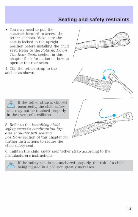
• You may need to pull theseatback forward to access thetether anchors. Make sure theseat is locked in the uprightposition before installing the childseat. Refer to the Folding DownThe Rear Seats section in thischapter for information on how tooperate the rear seats.
4. Clip the tether strap to theanchor as shown.
If the tether strap is clippedincorrectly, the child safety
seat may not be retained properlyin the event of a collision.
5. Refer to the Installing childsafety seats in combination lapand shoulder belt seatingpositions section of this chapter forfurther instructions to secure thechild safety seat.
6. Tighten the child safety seat tether strap according to themanufacturer’s instructions.
If the safety seat is not anchored properly, the risk of a childbeing injured in a collision greatly increases.
Seating and safety restraints
141
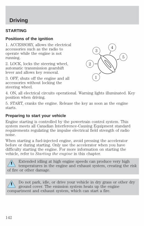
STARTING
Positions of the ignition1. ACCESSORY, allows the electricalaccessories such as the radio tooperate while the engine is notrunning.
2. LOCK, locks the steering wheel,automatic transmission gearshiftlever and allows key removal.
3. OFF, shuts off the engine and allaccessories without locking thesteering wheel.
4. ON, all electrical circuits operational. Warning lights illuminated. Keyposition when driving.
5. START, cranks the engine. Release the key as soon as the enginestarts.
Preparing to start your vehicleEngine starting is controlled by the powertrain control system. Thissystem meets all Canadian Interference-Causing Equipment standardrequirements regulating the impulse electrical field strength of radionoise.
When starting a fuel-injected engine, avoid pressing the acceleratorbefore or during starting. Only use the accelerator when you havedifficulty starting the engine. For more information on starting thevehicle, refer to Starting the engine in this chapter.
Extended idling at high engine speeds can produce very hightemperatures in the engine and exhaust system, creating the risk
of fire or other damage.
Do not park, idle, or drive your vehicle in dry grass or other dryground cover. The emission system heats up the engine
compartment and exhaust system, which can start a fire.
3
1
2
5
4
Driving
142

Do not start your vehicle in a closed garage or in other enclosedareas. Exhaust fumes can be toxic. Always open the garage door
before you start the engine. See Guarding against exhaust fumes inthis chapter for more instructions.
If you smell exhaust fumes inside your vehicle, have your dealerinspect your vehicle immediately. Do not drive if you smell
exhaust fumes.
Important safety precautionsA computer system controls the engine’s idle revolutions per minute(RPM). When the engine starts, the idle RPM runs faster to warm theengine. If the engine idle speed does not slow down automatically, havethe vehicle checked. Do not allow the vehicle to idle for more than 10minutes at the higher engine RPM.
Before starting the vehicle:
1. Make sure all vehicle occupants have buckled their safety belts. Formore information on safety belts and their proper usage, refer to theSeating and safety restraints chapter.
2. Make sure the headlamps and vehicle accessories are off.
3. Make sure the gearshift is in P(Park).
Driving
143

4. Make sure the parking brake isset.
5. Turn the key to 4 (ON) withoutturning the key to 5 (START).
If there is difficulty in turning thekey, firmly rotate the steering wheelleft and right until the key turnsfreely. This condition may occurwhen:
• front wheels are turned
• front wheel is against the curb
• steering wheel is turned when getting in or out of the vehicle
Make sure the corresponding lights illuminate or illuminate briefly. If alight fails to illuminate, have the vehicle serviced.
• If the driver’s safety belt is fastened, the light may not illuminate.
1
2
34
5
L
CE
L
H
FMPH RPMX1000
NAVIGATOR
km/hkm/h
DP RN D 2
LOW FUEL
BRAKESELECTRESET
DOORAJAR
4X4
LOWRANGE
CKSUSP
SERVICEENGINESOON
THEFT
20
40
60 80
60
40
20
00H
H
Driving
144
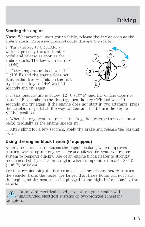
Starting the engineNote: Whenever you start your vehicle, release the key as soon as theengine starts. Excessive cranking could damage the starter.
1. Turn the key to 5 (START)without pressing the acceleratorpedal and release as soon as theengine starts. The key will return to4 (ON).
2. If the temperature is above –12°C (10° F) and the engine does notstart within five seconds on the firsttry, turn the key to OFF, wait 10seconds and try again.
3. If the temperature is below -12° C (10° F) and the engine does notstart in 15 seconds on the first try, turn the key OFF and wait 10seconds and try again. If the engine does not start in two attempts, pressthe accelerator pedal all the way to floor and hold. Turn the key toSTART position.
4. When the engine starts, release the key, then release the acceleratorpedal gradually as the engine speeds up.
5. After idling for a few seconds, apply the brake and release the parkingbrake.
Using the engine block heater (if equipped)An engine block heater warms the engine coolant, which improvesstarting, warms up the engine faster and allows the heater-defrostersystem to respond quickly. Use of an engine block heater is stronglyrecommended if you live in a region where temperatures reach -23° C(-10° F) or below.
For best results, plug the heater in at least three hours before startingthe vehicle. Using the heater for longer than three hours will not harmthe engine, so the heater can be plugged in the night before starting thevehicle.
To prevent electrical shock, do not use your heater withungrounded electrical systems or two-pronged (cheater)
adapters.
3
2
1
5
4
Driving
145

Guarding against exhaust fumesAlthough odorless and colorless, carbon monoxide is present in exhaustfumes. Take precautions to avoid its dangerous effects.
If you ever smell exhaust fumes of any kind inside your vehicle,have your dealer inspect and fix your vehicle immediately. Do
not drive if you smell exhaust fumes. These fumes are harmful andcould kill you.
Have the exhaust and body ventilation systems checked whenever:
• the vehicle is raised for service
• the sound of the exhaust system changes
• the vehicle has been damaged in a collision
WARNING: Engine exhaust, some of its constituents, andcertain vehicle components contain or emit chemicals known to
the State of California to cause cancer and birth defects or otherreproductive harm. In addition, certain fluids contained in vehicles andcertain products of component wear contain or emit chemicals knownto the State of California to cause cancer and birth defects or otherreproductive harm.
Important ventilating informationIf the engine is idling while the vehicle is stopped in an open area forlong periods of time, open the windows at least 2.5 cm (one inch).
Adjust the heating or air conditioning (if equipped) to bring in fresh air.
Improve vehicle ventilation by keeping all air inlet vents clear of snow,leaves and other debris.
BRAKESYour service brakes are self-adjusting. Refer to the scheduledmaintenance guide for scheduled maintenance.
Occasional brake noise is normal and often does not indicate aperformance concern with the vehicle’s brake system. In normaloperation, automotive brake systems may emit occasional or intermittentsqueal or groan noises when the brakes are applied. Such noises areusually heard during the first few brake applications in the morning;however, they may be heard at any time while braking and can be
Driving
146
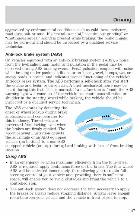
aggravated by environmental conditions such as cold, heat, moisture,road dust, salt or mud. If a “metal-to-metal,” “continuous grinding” or“continuous squeal” sound is present while braking, the brake liningsmay be worn-out and should be inspected by a qualified servicetechnician.
Anti-lock brake system (ABS)On vehicles equipped with an anti-lock braking system (ABS), a noisefrom the hydraulic pump motor and pulsation in the pedal may beobserved during ABS braking events. Pedal pulsation coupled with noisewhile braking under panic conditions or on loose gravel, bumps, wet orsnowy roads is normal and indicates proper functioning of the vehicle’santi-lock brake system. The ABS performs a self-check after you startthe engine and begin to drive away. A brief mechanical noise may beheard during this test. This is normal. If a malfunction is found, the ABSwarning light will come on. If the vehicle has continuous vibration orshudder in the steering wheel while braking, the vehicle should beinspected by a qualified service technician.
The ABS operates by detecting theonset of wheel lockup during brakeapplications and compensates forthis tendency. The wheels areprevented from locking even whenthe brakes are firmly applied. Theaccompanying illustration depictsthe advantage of an ABS equippedvehicle (on bottom) to a non-ABSequipped vehicle (on top) during hard braking with loss of front brakingtraction.
Using ABS• In an emergency or when maximum efficiency from the four-wheel
ABS is required, apply continuous force on the brake. The four wheelABS will be activated immediately, thus allowing you to retain fullsteering control of your vehicle and, providing there is sufficientspace, will enable you to avoid obstacles and bring the vehicle to acontrolled stop.
• The anti-lock system does not decrease the time necessary to applythe brakes or always reduce stopping distance. Always leave enoughroom between your vehicle and the vehicle in front of you to stop.
Driving
147
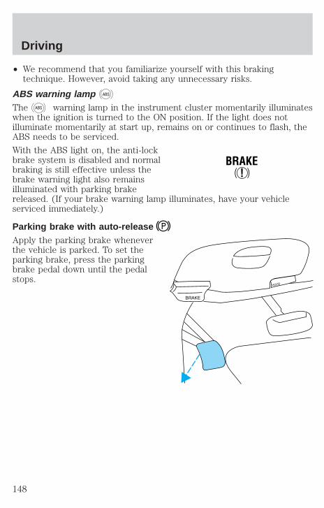
• We recommend that you familiarize yourself with this brakingtechnique. However, avoid taking any unnecessary risks.
ABS warning lamp ABS
The ABS warning lamp in the instrument cluster momentarily illuminateswhen the ignition is turned to the ON position. If the light does notilluminate momentarily at start up, remains on or continues to flash, theABS needs to be serviced.
With the ABS light on, the anti-lockbrake system is disabled and normalbraking is still effective unless thebrake warning light also remainsilluminated with parking brakereleased. (If your brake warning lamp illuminates, have your vehicleserviced immediately.)
Parking brake with auto-releaseApply the parking brake wheneverthe vehicle is parked. To set theparking brake, press the parkingbrake pedal down until the pedalstops.
!BRAKE
Driving
148
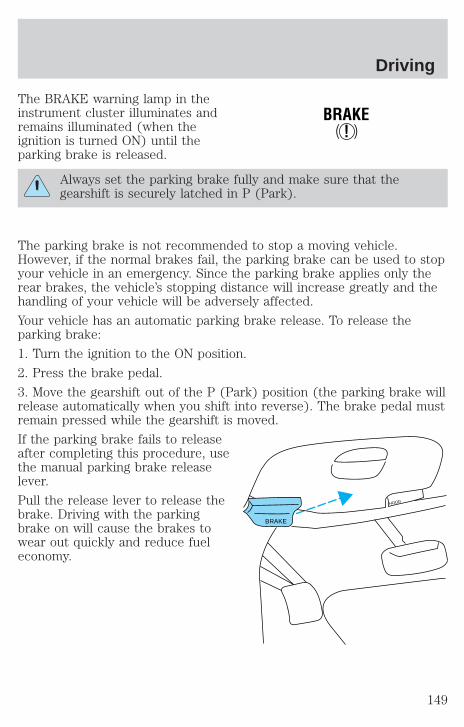
The BRAKE warning lamp in theinstrument cluster illuminates andremains illuminated (when theignition is turned ON) until theparking brake is released.
Always set the parking brake fully and make sure that thegearshift is securely latched in P (Park).
The parking brake is not recommended to stop a moving vehicle.However, if the normal brakes fail, the parking brake can be used to stopyour vehicle in an emergency. Since the parking brake applies only therear brakes, the vehicle’s stopping distance will increase greatly and thehandling of your vehicle will be adversely affected.
Your vehicle has an automatic parking brake release. To release theparking brake:
1. Turn the ignition to the ON position.
2. Press the brake pedal.
3. Move the gearshift out of the P (Park) position (the parking brake willrelease automatically when you shift into reverse). The brake pedal mustremain pressed while the gearshift is moved.
If the parking brake fails to releaseafter completing this procedure, usethe manual parking brake releaselever.
Pull the release lever to release thebrake. Driving with the parkingbrake on will cause the brakes towear out quickly and reduce fueleconomy.
!BRAKE
BRAKE
HOOD
Driving
149
STEERINGYour vehicle is equipped with power steering. Power steering uses energyfrom the engine to help steer the vehicle.
To prevent damage to the power steering pump:
• Never hold the steering wheel to the extreme right or the extreme leftfor more than a few seconds when the engine is running.
• Do not operate the vehicle with a low power steering pump fluid level(below the MIN mark on the reservoir).
If the power steering system breaks down (or if the engine is turnedoff), you can steer the vehicle manually, but it takes more effort.
If the steering wanders or pulls, the condition could be caused by any ofthe following:
• underinflated tire(s) on any wheel(s)
• uneven vehicle loading
• high crown in center of road
• high crosswinds
• wheels out of alignment
• loose or worn suspension components
Speed sensitive steeringYour vehicle is equipped with speed sensitive, variable assist powersteering (VAPS). At high speeds, steering assist will increase to improvelow speed maneuverability.
If the amount of effort required to steer your vehicle changes whiledriving at a constant vehicle speed, have the power steering systemchecked by your dealer or a qualified service technician.
AIR SUSPENSION SYSTEM (IF EQUIPPED)The air suspension system is designed to improve ride, handling andgeneral vehicle performance for static, on and off-road driving conditions.
• The load leveling feature of the air suspension automatically keeps thevehicle at a constant level if a load is added or removed from thevehicle.
Driving
150

• The height adjustment feature automatically controls the vehicleheight over a range of approximately 5 cm (2 inches) based on vehiclespeed, ignition position and selection of two or four-wheel drivemodes.
• The air suspension automatically puts the vehicle at its lowest heightwhen ignition is OFF to provide easy entry and exit. Whenever a dooris opened (including the liftgate) the system memorizes and maintainsthe height of the vehicle until all doors are closed or until vehicleexceeds 16 km/h (10 mph).
• The air suspension system raises the vehicle to its normal rideposition when the ignition is turned on, all doors are closed and thetransmission is shifted into gear.
• In 4WD Low the air suspension system will not move to its lowestheight. In 4WD Low, the air suspension system raises the vehicleabove the normal ride height at speeds below 40 km/h (25 mph) toimprove ground clearance. In 4WD Low, do not exceed 56 km/h (35mph).
• When the vehicle is in motion, the air suspension system will adjustthe vehicle’s height according to ground clearance and speed tomaximize ride comfort.
• It is normal to occasionally hear a buzz or clicking from the vehicle’sair suspension system when the ignition is turned off. The systemstays energized for 40 minutes after the ignition is turned off tocompensate for any load changes made after the vehicle is parked.
The air suspension shut-off switch islocated behind an access panelunderneath the passenger sideinstrument panel.
On vehicles equipped withAir Suspension, turn OFF
the Air Suspension switch prior tojacking, hoisting or towing yourvehicle.
Normal vehicle operation does notrequire any action by the driver.
AIR SUSPENSIONSWITCH
INTERRUPTEUR DELA SUSPENSIONPNEUMATIQUE
OFF
Driving
151
Check air suspension indicator lightThe warning and indicator light CK SUSP illuminates when the airsuspension switch is turned off or an air suspension system fault hasbeen detected.
If the light is illuminated while driving and the air suspension systemswitch is not turned off, safely pull off the road at your earliestconvenience. Turn the ignition switch from 4 (On) to 3 (Off) and 4 (On)again. If the warning light illuminates again, turn the air suspensionswitch off and have the vehicle serviced by a dealer or qualified servicetechnician.
If the vehicle is loaded beyond the recommended maximum payload, theCK SUSP light may illuminate. To correct this condition, remove orredistribute the payload according to the recommended requirementsand follow the procedure outlined above.
TRACTION-LOK AXLE (IF EQUIPPED)This axle provides added traction on slippery surfaces, particularly whenone wheel is on a poor traction surface. Under normal conditions, theTraction-Lok axle functions like a standard rear axle.
Extended use of other than the manufacturer’s specified size tires on aTraction-Lok rear axle could result in a permanent reduction ineffectiveness. This loss of effectiveness does not affect normal drivingand should not be noticeable to the driver.
To avoid injury, never run the engine with one wheel off theground, such as when changing a tire.
PREPARING TO DRIVE YOUR VEHICLE
Utility vehicles have a significantly higher rollover rate thanother types of vehicles.
In a rollover crash, an unbelted person is significantly more likelyto die than a person wearing a seat belt.
Your vehicle has special design and equipment features to make itcapable of performing in a wide variety of circumstances. These specialdesign features, such as larger tires and increased ground clearance, givethe vehicle a higher center of gravity than a passenger car.
Driving
152
Vehicles with a higher center of gravity such as utility andfour-wheel drive vehicles handle differently than vehicles with a
lower center of gravity. Utility and four-wheel drive vehicles are notdesigned for cornering at speeds as high as passenger cars any morethan low-slung sports cars are designed to perform satisfactorily underoff-road conditions. Avoid sharp turns, excessive speed and abruptmaneuvers in these vehicles. Failure to drive cautiously could result inan increased risk of vehicle rollover, personal injury and death.
Loaded vehicles, with a higher center of gravity, may handledifferently than unloaded vehicles. Extra precautions, such as
slower speeds and increased stopping distance, should be taken whendriving a heavily loaded vehicle.
Your vehicle has the capability to haul more cargo and people than mostpassenger cars. Depending upon the type and placement of the load,hauling people and cargo may raise the center of gravity of the vehicle.
Use extra caution while becoming familiar with your vehicle. Know thecapabilities and limitations of both you as a driver and your vehicle.
AUTOMATIC TRANSMISSION OPERATION
Brake-shift interlockThis vehicle is equipped with a brake-shift interlock feature that preventsthe gearshift lever from being moved from P (Park) when the ignition isin the ON position unless brake pedal is depressed.
If you cannot move the gearshift lever out of P (Park) with ignition inthe ON position and the brake pedal depressed:
1. Apply the parking brake, turn ignition key to LOCK, then remove thekey.
2. Insert the key and turn it to OFF. Apply the brake pedal and shiftto N (Neutral).
3. Start the vehicle.
If it is necessary to use the above procedure to move the gearshift lever,it is possible that a fuse has blown or the vehicle’s brakelamps are notoperating properly. Refer to Fuses and relays in the Roadsideemergencies chapter.
Driving
153
Do not drive your vehicle until you verify that the brakelampsare working.
If your vehicle gets stuck in mud or snow it may be rocked out byshifting from forward and reverse gears, stopping between shifts, in asteady pattern. Press lightly on the accelerator in each gear.
Do not rock the vehicle if the engine is not at normal operatingtemperature or damage to the transmission may occur.
Do not rock the vehicle for more than a few minutes or damageto the transmission and tires may occur or the engine mayoverheat.
Always set the parking brake fully and make sure the gearshift islatched in P (Park). Turn off the ignition whenever you leave
your vehicle.
If the parking brake is fully released, but the brake warning lampremains illuminated, the brakes may not be working properly.
See your dealer or a qualified service technician.
Driving with a 4–speed automatic transmissionYour vehicle’s automatic transmission is equipped with a special shiftstrategy that insures maximum heater performance during cold weatheroperation.
When ambient temperature is –5° C (23° F) or below and the enginecoolant temperature is below 38° C (100° F), light throttle upshifts maybe slightly delayed. Once the engine coolant temperature reaches 71° C(160° F) the normal shift strategy will resume. This is normal operationand will not affect the function or the durability of the transmission.
If the normal shift strategy does not resume once the enginecoolant temperature reaches the normal operating temperature,or if the downshifts and other throttle conditions do not functionnormally, see your dealer or a qualified service technician as soonas possible.
Understanding gearshift positionsTo put your vehicle in gear, start the engine, depress the brake pedal,then move gearshift lever out of P (Park).
Driving
154
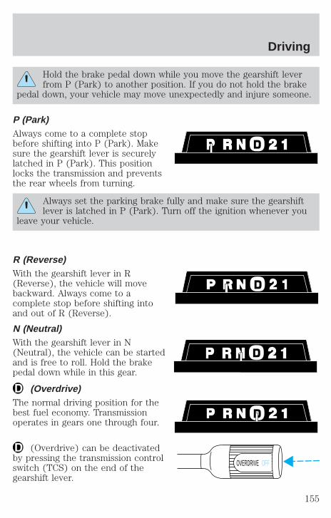
Hold the brake pedal down while you move the gearshift leverfrom P (Park) to another position. If you do not hold the brake
pedal down, your vehicle may move unexpectedly and injure someone.
P (Park)Always come to a complete stopbefore shifting into P (Park). Makesure the gearshift lever is securelylatched in P (Park). This positionlocks the transmission and preventsthe rear wheels from turning.
Always set the parking brake fully and make sure the gearshiftlever is latched in P (Park). Turn off the ignition whenever you
leave your vehicle.
R (Reverse)With the gearshift lever in R(Reverse), the vehicle will movebackward. Always come to acomplete stop before shifting intoand out of R (Reverse).
N (Neutral)With the gearshift lever in N(Neutral), the vehicle can be startedand is free to roll. Hold the brakepedal down while in this gear.
(Overdrive)The normal driving position for thebest fuel economy. Transmissionoperates in gears one through four.
(Overdrive) can be deactivatedby pressing the transmission controlswitch (TCS) on the end of thegearshift lever.
OVERDRIVE OFF
Driving
155
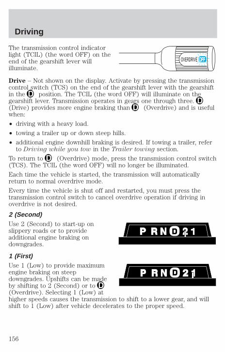
The transmission control indicatorlight (TCIL) (the word OFF) on theend of the gearshift lever willilluminate.
Drive – Not shown on the display. Activate by pressing the transmissioncontrol switch (TCS) on the end of the gearshift lever with the gearshiftin the position. The TCIL (the word OFF) will illuminate on thegearshift lever. Transmission operates in gears one through three.(Drive) provides more engine braking than (Overdrive) and is usefulwhen:
• driving with a heavy load.
• towing a trailer up or down steep hills.
• additional engine downhill braking is desired. If towing a trailer, referto Driving while you tow in the Trailer towing section.
To return to (Overdrive) mode, press the transmission control switch(TCS). The TCIL (the word OFF) will no longer be illuminated.
Each time the vehicle is started, the transmission will automaticallyreturn to normal overdrive mode.
Every time the vehicle is shut off and restarted, you must press thetransmission control switch to cancel overdrive operation if driving inoverdrive is not desired.
2 (Second)Use 2 (Second) to start-up onslippery roads or to provideadditional engine braking ondowngrades.
1 (First)Use 1 (Low) to provide maximumengine braking on steepdowngrades. Upshifts can be madeby shifting to 2 (Second) or to(Overdrive). Selecting 1 (Low) athigher speeds causes the transmission to shift to a lower gear, and willshift to 1 (Low) after vehicle decelerates to the proper speed.
OVERDRIVE
Driving
156

Forced DownshiftsTo gain acceleration in (Overdrive) or Drive (O/D OFF) whenpassing another vehicle, push the accelerator to the floor. Thetransmission will downshift to the appropriate gear: third, second or firstgear.
Shift strategy (4R100 automatic transmission)To account for customer driving habits and conditions, your 4R100automatic transmission electronically controls the shift quality by usingan adaptive learning strategy. The adaptive learning strategy ismaintained by power from the battery. When the battery is disconnectedor a new battery is installed, the transmission must relearn its adaptivestrategy. Optimal shifting will resume within a few hundred kilometers(miles) of operation.
If the shift quality does not improve within a few hundredkilometers (miles) of operation, or if the downshifts and otherthrottle conditions do not function normally, see your dealer or aqualified service technician as soon as possible.
REVERSE SENSING SYSTEM (IF EQUIPPED)The reverse sensing system (RSS) sounds a tone to warn the driver ofobstacles near the rear bumper when the reverse gear is selected.
To help avoid personal injury, please read and understand thelimitations on the reverse sensing system described below.
Reverse sensing is only an assist for some (generally large and fixed)objects when moving in reverse on a flat surface at “parking speeds” ofapproximately 4.8 km/h (3 mph) or less. The weather may also affectthe function of RSS. RSS may have reduced performance, or beactivated in inclement weather. It is the driver’s responsibility forensuring that their path is clear when operating the vehicle.
To help avoid personal injury, always use caution when inreverse and when using the reverse sensing system.
Driving
157
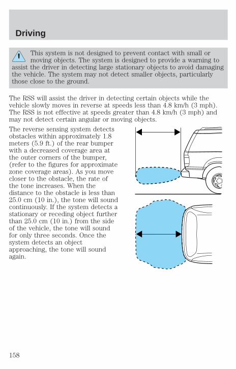
This system is not designed to prevent contact with small ormoving objects. The system is designed to provide a warning to
assist the driver in detecting large stationary objects to avoid damagingthe vehicle. The system may not detect smaller objects, particularlythose close to the ground.
The RSS will assist the driver in detecting certain objects while thevehicle slowly moves in reverse at speeds less than 4.8 km/h (3 mph).The RSS is not effective at speeds greater than 4.8 km/h (3 mph) andmay not detect certain angular or moving objects.
The reverse sensing system detectsobstacles within approximately 1.8meters (5.9 ft.) of the rear bumperwith a decreased coverage area atthe outer corners of the bumper,(refer to the figures for approximatezone coverage areas). As you movecloser to the obstacle, the rate ofthe tone increases. When thedistance to the obstacle is less than25.0 cm (10 in.), the tone will soundcontinuously. If the system detects astationary or receding object furtherthan 25.0 cm (10 in.) from the sideof the vehicle, the tone will soundfor only three seconds. Once thesystem detects an objectapproaching, the tone will soundagain.
Driving
158
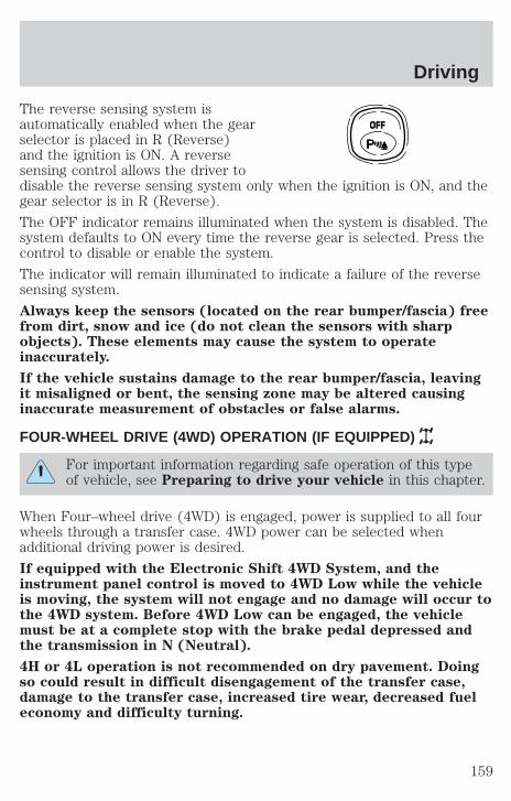
The reverse sensing system isautomatically enabled when the gearselector is placed in R (Reverse)and the ignition is ON. A reversesensing control allows the driver todisable the reverse sensing system only when the ignition is ON, and thegear selector is in R (Reverse).
The OFF indicator remains illuminated when the system is disabled. Thesystem defaults to ON every time the reverse gear is selected. Press thecontrol to disable or enable the system.
The indicator will remain illuminated to indicate a failure of the reversesensing system.
Always keep the sensors (located on the rear bumper/fascia) freefrom dirt, snow and ice (do not clean the sensors with sharpobjects). These elements may cause the system to operateinaccurately.
If the vehicle sustains damage to the rear bumper/fascia, leavingit misaligned or bent, the sensing zone may be altered causinginaccurate measurement of obstacles or false alarms.
FOUR-WHEEL DRIVE (4WD) OPERATION (IF EQUIPPED)
For important information regarding safe operation of this typeof vehicle, see Preparing to drive your vehicle in this chapter.
When Four–wheel drive (4WD) is engaged, power is supplied to all fourwheels through a transfer case. 4WD power can be selected whenadditional driving power is desired.
If equipped with the Electronic Shift 4WD System, and theinstrument panel control is moved to 4WD Low while the vehicleis moving, the system will not engage and no damage will occur tothe 4WD system. Before 4WD Low can be engaged, the vehiclemust be at a complete stop with the brake pedal depressed andthe transmission in N (Neutral).
4H or 4L operation is not recommended on dry pavement. Doingso could result in difficult disengagement of the transfer case,damage to the transfer case, increased tire wear, decreased fueleconomy and difficulty turning.
OFF
Driving
159
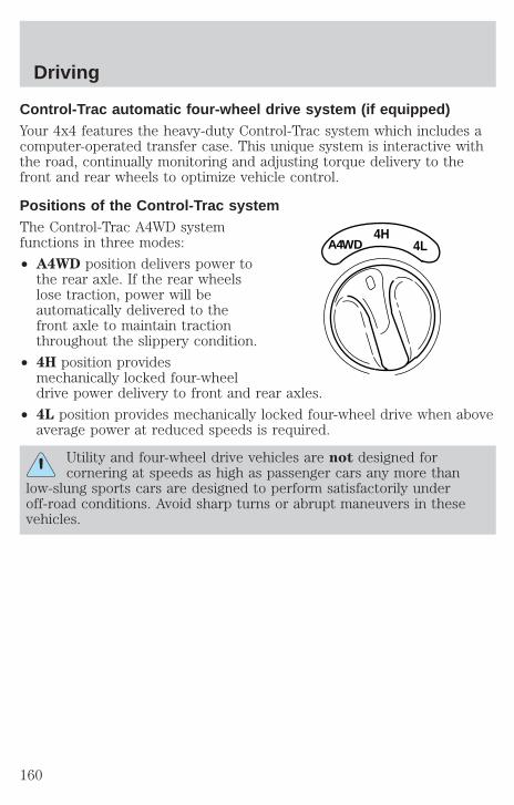
Control-Trac automatic four-wheel drive system (if equipped)Your 4x4 features the heavy-duty Control-Trac system which includes acomputer-operated transfer case. This unique system is interactive withthe road, continually monitoring and adjusting torque delivery to thefront and rear wheels to optimize vehicle control.
Positions of the Control-Trac systemThe Control-Trac A4WD systemfunctions in three modes:
• A4WD position delivers power tothe rear axle. If the rear wheelslose traction, power will beautomatically delivered to thefront axle to maintain tractionthroughout the slippery condition.
• 4H position providesmechanically locked four-wheeldrive power delivery to front and rear axles.
• 4L position provides mechanically locked four-wheel drive when aboveaverage power at reduced speeds is required.
Utility and four-wheel drive vehicles are not designed forcornering at speeds as high as passenger cars any more than
low-slung sports cars are designed to perform satisfactorily underoff-road conditions. Avoid sharp turns or abrupt maneuvers in thesevehicles.
4HA4WD 4L
Driving
160
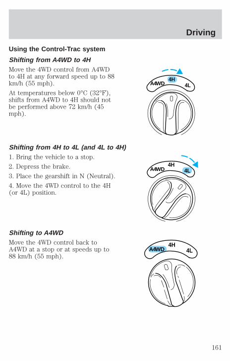
Using the Control-Trac system
Shifting from A4WD to 4HMove the 4WD control from A4WDto 4H at any forward speed up to 88km/h (55 mph).
At temperatures below 0°C (32°F),shifts from A4WD to 4H should notbe performed above 72 km/h (45mph).
Shifting from 4H to 4L (and 4L to 4H)1. Bring the vehicle to a stop.
2. Depress the brake.
3. Place the gearshift in N (Neutral).
4. Move the 4WD control to the 4H(or 4L) position.
Shifting to A4WDMove the 4WD control back toA4WD at a stop or at speeds up to88 km/h (55 mph).
4HA4WD 4L
4HA4WD 4L
4HA4WD 4L
Driving
161
Driving off-road with truck and utility vehicles4WD vehicles are specially equipped for driving on sand, snow, mud andrough terrain and have operating characteristics that are somewhatdifferent from conventional vehicles, both on and off the road.
How your vehicle differs from other vehiclesTruck and utility vehicles can differ from some other vehicles. Yourvehicle may be higher to allow it to travel over rough terrain withoutgetting hung up or damaging underbody components.
The differences that make your vehicle so versatile also make it handledifferently than an ordinary passenger car.
Maintain steering wheel control at all times, especially in rough terrain.Since sudden changes in terrain can result in abrupt steering wheelmotion, make sure you grip the steering wheel from the outside. Do notgrip the spokes.
Drive cautiously to avoid vehicle damage from concealed objects such asrocks and stumps.
You should either know the terrain or examine maps of the area beforedriving. Map out your route before driving in the area. To maintainsteering and braking control of your vehicle, you must have all fourwheels on the ground and they must be rolling, not sliding or spinning.
Basic operating principles• Do not use 4WD on dry, hard surfaced roads (except models equipped
with Auto 4WD). This may damage the drivelines and axles.
• Drive slower in strong crosswinds which can affect the normal steeringcharacteristics of your vehicle.
• Be extremely careful when driving on pavement made slippery byloose sand, water, gravel, snow or ice.
If your vehicle goes off the edge of the pavement• If your vehicle goes off the edge of the pavement, slow down, but
avoid severe brake application, Ease the vehicle back onto thepavement only after reducing your speed. Do not turn the steeringwheel too sharply while returning to the road surface.
• It may be safer to stay on the apron or shoulder of the road and slowdown gradually before returning to the pavement. You may loosecontrol if you do not slow down or if you turn the steering wheel toosharply or abruptly.
Driving
162
• It often may be less risky to strike small inanimate objects, such ashighway reflectors, with minor damage to your vehicle rather thanattempt a sudden return to the pavement which could cause thevehicle to slide sideways out of control or roll over. Remember, yoursafety and the safety of others should be your primary concern.
If your vehicle gets stuckIf the vehicle is stuck it may be rocked out by shifting from forward andreverse gears, stopping between shifts, in a steady pattern. Press lightlyon the accelerator in each gear.
Do not rock the vehicle for more than a few minutes or damageto the transmission and tires may occur or the engine mayoverheat.
Do not spin the wheels at over 56 km/h (35 mph). The tires mayfail and injure a passenger or bystander.
Emergency maneuvers• In an unavoidable emergency situation where a sudden sharp turn
must be made, remember to avoid “over-driving” your vehicle, i.e.,turn the steering wheel only as rapidly and as far as required to avoidthe emergency. Excessive steering will result in less vehicle control,not more. Additionally, smooth variations of the accelerator and/orbrake pedal pressure should be utilized if changes in vehicle speed arecalled for. Avoid abrupt steering, acceleration or braking. Use allavailable road surface to return the vehicle to a safe direction oftravel.
• In the event of an emergency stop, avoid skidding the tires and do notattempt any sharp steering wheel movements.
• If the vehicle goes from one type of surface to another (i.e., fromconcrete to gravel) there will be a change in the way the vehicleresponds to a maneuver (steering, acceleration or barking). Again,avoid these abrupt inputs.
ParkingOn some 4WD vehicles, when the transfer case is in the N (Neutral)position, the engine and transmission are disconnected from the rest ofthe driveline. Therefore, the vehicle is free to roll even if the automatictransmission is in P (Park) or the manual transmission is in gear. Do notleave the vehicle unattended with the transfer case in N (Neutral)
Driving
163
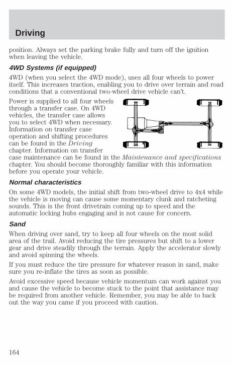
position. Always set the parking brake fully and turn off the ignitionwhen leaving the vehicle.
4WD Systems (if equipped)4WD (when you select the 4WD mode), uses all four wheels to poweritself. This increases traction, enabling you to drive over terrain and roadconditions that a conventional two-wheel drive vehicle can’t.
Power is supplied to all four wheelsthrough a transfer case. On 4WDvehicles, the transfer case allowsyou to select 4WD when necessary.Information on transfer caseoperation and shifting procedurescan be found in the Drivingchapter. Information on transfercase maintenance can be found in the Maintenance and specificationschapter. You should become thoroughly familiar with this informationbefore you operate your vehicle.
Normal characteristicsOn some 4WD models, the initial shift from two-wheel drive to 4x4 whilethe vehicle is moving can cause some momentary clunk and ratchetingsounds. This is the front drivetrain coming up to speed and theautomatic locking hubs engaging and is not cause for concern.
SandWhen driving over sand, try to keep all four wheels on the most solidarea of the trail. Avoid reducing the tire pressures but shift to a lowergear and drive steadily through the terrain. Apply the accelerator slowlyand avoid spinning the wheels.
If you must reduce the tire pressure for whatever reason in sand, makesure you re-inflate the tires as soon as possible.
Avoid excessive speed because vehicle momentum can work against youand cause the vehicle to become stuck to the point that assistance maybe required from another vehicle. Remember, you may be able to backout the way you came if you proceed with caution.
Driving
164
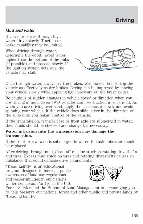
Mud and waterIf you must drive through highwater, drive slowly. Traction orbrake capability may be limited.
When driving through water,determine the depth; avoid waterhigher than the bottom of the hubs(if possible) and proceed slowly. Ifthe ignition system gets wet, thevehicle may stall.
Once through water, always try the brakes. Wet brakes do not stop thevehicle as effectively as dry brakes. Drying can be improved by movingyour vehicle slowly while applying light pressure on the brake pedal.
Be cautious of sudden changes in vehicle speed or direction when youare driving in mud. Even 4WD vehicles can lose traction in slick mud. Aswhen you are driving over sand, apply the accelerator slowly and avoidspinning your wheels. If the vehicle does slide, steer in the direction ofthe slide until you regain control of the vehicle.
If the transmission, transfer case or front axle are submerged in water,their fluids should be checked and changed, if necessary.
Water intrusion into the transmission may damage thetransmission.
If the front or rear axle is submerged in water, the axle lubricant shouldbe replaced.
After driving through mud, clean off residue stuck to rotating driveshaftsand tires. Excess mud stuck on tires and rotating driveshafts causes animbalance that could damage drive components.
“Tread Lightly” is an educationalprogram designed to increase publicawareness of land-use regulationsand responsibilities in our nationswilderness areas. Ford joins the U.S.Forest Service and the Bureau of Land Management in encouraging youto help preserve our national forest and other public and private lands by“treading lightly.”
Driving
165
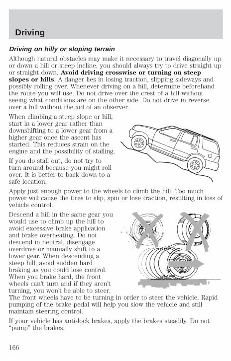
Driving on hilly or sloping terrainAlthough natural obstacles may make it necessary to travel diagonally upor down a hill or steep incline, you should always try to drive straight upor straight down. Avoid driving crosswise or turning on steepslopes or hills. A danger lies in losing traction, slipping sideways andpossibly rolling over. Whenever driving on a hill, determine beforehandthe route you will use. Do not drive over the crest of a hill withoutseeing what conditions are on the other side. Do not drive in reverseover a hill without the aid of an observer.
When climbing a steep slope or hill,start in a lower gear rather thandownshifting to a lower gear from ahigher gear once the ascent hasstarted. This reduces strain on theengine and the possibility of stalling.
If you do stall out, do not try toturn around because you might rollover. It is better to back down to asafe location.
Apply just enough power to the wheels to climb the hill. Too muchpower will cause the tires to slip, spin or lose traction, resulting in loss ofvehicle control.
Descend a hill in the same gear youwould use to climb up the hill toavoid excessive brake applicationand brake overheating. Do notdescend in neutral, disengageoverdrive or manually shift to alower gear. When descending asteep hill, avoid sudden hardbraking as you could lose control.When you brake hard, the frontwheels can’t turn and if they aren’tturning, you won’t be able to steer.The front wheels have to be turning in order to steer the vehicle. Rapidpumping of the brake pedal will help you slow the vehicle and stillmaintain steering control.
If your vehicle has anti-lock brakes, apply the brakes steadily. Do not“pump” the brakes.
Driving
166
Driving on snow and ice4WD vehicles have advantages over 2WD vehicles in snow and ice butcan skid like any other vehicle.
Should you start to slide while driving on snowy or icy roads, turn thesteering wheel in the direction of the slide until you regain control.
Avoid sudden applications of power and quick changes of direction onsnow and ice. Apply the accelerator slowly and steadily when startingfrom a full stop.
Avoid sudden braking as well. Although a 4WD vehicle may acceleratebetter than a two-wheel drive vehicle in snow and ice, it won’t stop anyfaster, because as in other vehicles, braking occurs at all four wheels. Donot become overconfident as to road conditions.
Make sure you allow sufficient distance between you and other vehiclesfor stopping as well as drive slower than usual and consider using one ofthe lower gears. In emergency stopping situations, avoid locking of thewheels. Use a “squeeze” technique, push on the brake pedal with asteadily increasing force which allows the wheels to brake yet continueto roll so that you may steer in the direction you want to travel. If youlock the wheels, release the brake pedal and repeat the squeezetechnique. If your vehicle is equipped with a Four Wheel Anti-LockBrake System (ABS), apply the brake steadily. Do not “pump” thebrakes. Refer to the Brakes section of this chapter for additionalinformation on the operation of the anti-lock brake system.
Never drive with chains on the front tires of 4WD vehicles without alsoputting them on the rear tires. This could cause the rear to slide andswing around during braking.
Tires, Replacement Requirements4WD vehicles are equipped with tires designed to provide for safe rideand handling capability.
Do not use a size and type of tire and wheel other than that originallyprovided by Ford because it can affect the safety and performance ofyour vehicle, which could lead to loss of vehicle control or roll over andserious injury. Make sure all tires and wheels on the vehicle are of thesame size, type, tread design, brand and load-carrying capacity. If youhave questions regarding tire replacement, see an authorized Ford orLincoln/Mercury dealer.
Driving
167
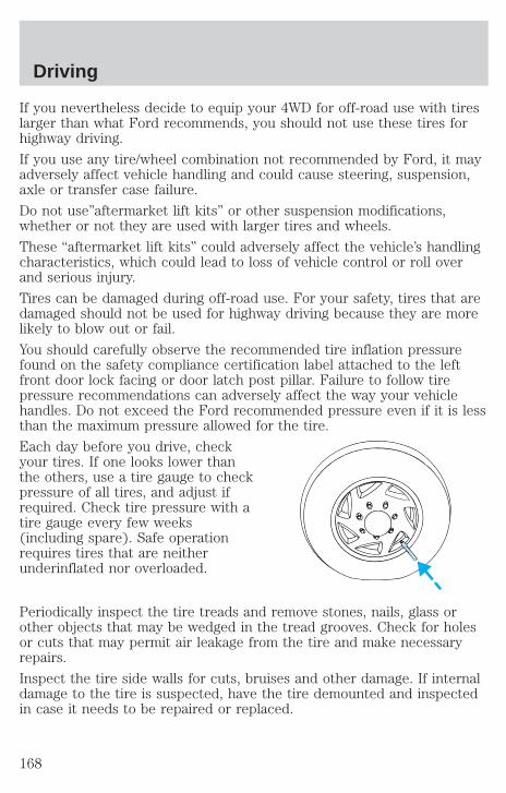
If you nevertheless decide to equip your 4WD for off-road use with tireslarger than what Ford recommends, you should not use these tires forhighway driving.
If you use any tire/wheel combination not recommended by Ford, it mayadversely affect vehicle handling and could cause steering, suspension,axle or transfer case failure.
Do not use”aftermarket lift kits” or other suspension modifications,whether or not they are used with larger tires and wheels.
These “aftermarket lift kits” could adversely affect the vehicle’s handlingcharacteristics, which could lead to loss of vehicle control or roll overand serious injury.
Tires can be damaged during off-road use. For your safety, tires that aredamaged should not be used for highway driving because they are morelikely to blow out or fail.
You should carefully observe the recommended tire inflation pressurefound on the safety compliance certification label attached to the leftfront door lock facing or door latch post pillar. Failure to follow tirepressure recommendations can adversely affect the way your vehiclehandles. Do not exceed the Ford recommended pressure even if it is lessthan the maximum pressure allowed for the tire.
Each day before you drive, checkyour tires. If one looks lower thanthe others, use a tire gauge to checkpressure of all tires, and adjust ifrequired. Check tire pressure with atire gauge every few weeks(including spare). Safe operationrequires tires that are neitherunderinflated nor overloaded.
Periodically inspect the tire treads and remove stones, nails, glass orother objects that may be wedged in the tread grooves. Check for holesor cuts that may permit air leakage from the tire and make necessaryrepairs.
Inspect the tire side walls for cuts, bruises and other damage. If internaldamage to the tire is suspected, have the tire demounted and inspectedin case it needs to be repaired or replaced.
Driving
168
Maintenance and ModificationsThe suspension and steering systems on your vehicle have been designedand tested to provide both reasonably safe, predictable performancewhether loaded or empty and durable load carrying capability. For thisreason, Ford strongly recommends that you do not make modificationssuch as adding or removing parts (such as lift kits or stabilizer bars) orby using replacement parts not equivalent to the original factoryequipment.
Any modifications to a vehicle that raise the center of gravity can makeit more likely the vehicle will roll over as a result of a loss of control.Ford recommends that caution be used with any vehicle equipped with ahigh load or device (such as ladder racks or pickup box cover).
Failure to maintain your vehicle properly may void the warranty, increaseyour repair cost, reduce vehicle performance and operational capabilitiesand adversely affect driver and passenger safety. Frequent inspection ofvehicle chassis components is recommended if the vehicle is subjected toheavy off-road usage.
DRIVING THROUGH WATERDo not drive quickly through standing water, especially if the depth isunknown. Traction or brake capability may be limited and if the ignitionsystem gets wet, your engine may stall. Water may also enter yourengine’s air intake and severely damage your engine.
If driving through deep or standing water is unavoidable, proceed veryslowly. Never drive through water that is higher than the bottom of thehubs (for trucks) or the bottom of the wheel rims (for cars).
Once through the water, always try the brakes. Wet brakes do not stopthe vehicle as effectively as dry brakes. Drying can be improved bymoving your vehicle slowly while applying light pressure on the brakepedal.
Driving through deep water where the transmission vent tube issubmerged may allow water into the transmission and causeinternal transmission damage.
Driving
169
VEHICLE LOADINGBefore loading a vehicle, familiarize yourself with the following terms:
• Base Curb Weight: Weight of the vehicle including any standardequipment, fluids, lubricants, etc. It does not include occupants oraftermarket equipment.
• Payload: Combined maximum allowable weight of cargo, occupantsand optional equipment. The payload equals the gross vehicle weightrating minus base curb weight.
• GVW (Gross Vehicle Weight): Base curb weight plus payloadweight. The GVW is not a limit or a specification.
• GVWR (Gross Vehicle Weight Rating): Maximum permissable totalweight of the base vehicle, occupants, optional equipment and cargo.The GVWR is specific to each vehicle and is listed on the SafetyCertification Label on the driver’s door pillar.
• GAWR (Gross Axle Weight Rating): Carrying capacity for each axlesystem. The GAWR is specific to each vehicle and is listed on theSafety Certification Label on the driver’s door pillar.
• GCW (Gross Combined Weight): The combined weight of thetowing vehicle (including occupants and cargo) and the loaded trailer.
• GCWR (Gross Combined Weight Rating): Maximum permissablecombined weight of towing vehicle (including occupants and cargo)and the loaded trailer
• Maximum Trailer Weight Rating: Maximum weight of a trailer thevehicle is permitted to tow. The maximum trailer weight rating isdetermined by subtracting the vehicle curb weight for each engine/transmission combination, any required option weight for trailer towingand the weight of the driver from the GCWR for the towing vehicle.
• Maximum Trailer Weight: Maximum weight of a trailer the loadedvehicle (including occupants and cargo) is permitted to tow. It isdetermined by subtracting the weight of the loaded trailer towingvehicle from the GCWR for the towing vehicle.
• Trailer Weight Range: Specified weight range that the trailer mustfall within that ranges from zero to the maximum trailer weight rating.
Remember to figure in the tongue load of your loaded trailer whenfiguring the total weight.
Driving
170
Do not exceed the GVWR or the GAWR specified on thecertification label.
Do not use replacement tires with lower load carrying capacities than theoriginals because they may lower the vehicle’s GVWR and GAWRlimitations. Replacement tires with a higher limit than the originals donot increase the GVWR and GAWR limitations.
The Safety Certification Label, found on the driver’s door pillar, listsseveral important vehicle weight rating limitations. Before adding anyadditional equipment, refer to these limitations. If you are adding weightto the front of your vehicle, (potentially including weight added to thecab), the weight added should not exceed the front axle reserve capacity(FARC). Additional frontal weight may be added to the front axle reservecapacity provided you limit your payload in other ways (i.e. restrict thenumber of occupants or amount of cargo carried).
Always ensure that the weight of occupants, cargo and equipment beingcarried is within the weight limitations that have been established foryour vehicle including both gross vehicle weight and front and rear grossaxle weight rating limits. Under no circumstance should these limitationsbe exceeded.
Exceeding any vehicle weight rating limitation could result inserious damage to the vehicle and/or personal injury.
Special loading instructions for owners of pickup trucks andutility-type vehicles
For important information regarding safe operation of this typeof vehicle, see the Preparing to drive your vehicle section in
this chapter.
Loaded vehicles, with a higher center of gravity, may handledifferently than unloaded vehicles. Extra precautions, such as
slower speeds and increased stopping distance, should be taken whendriving a heavily loaded vehicle.
Your vehicle has the capability to haul more cargo and people than mostpassenger cars. Depending upon the type and placement of the load,hauling cargo and people may raise the center of gravity of the vehicle.
Driving
171

Calculating the load your vehicle can carry/tow1. Use the appropriate maximum gross combined weight rating (GCWR)chart to find the maximum GCWR for your type engine and rear axleratio.
2. Weigh your vehicle as you customarily operate the vehicle withoutcargo. To obtain correct weights, try taking your vehicle to a shippingcompany or an inspection station for trucks.
3. Subtract your loaded vehicle weight from the maximum GCWR on thefollowing charts. This is the maximum trailer weight your vehicle can towand must fall below the maximum shown under maximum trailer weighton the chart.
TRAILER TOWINGTrailer towing puts additional loads on your vehicle’s engine,transmission, axle, brakes, tires, and suspension. For your safety and tomaximize vehicle performance, be sure to use the proper equipmentwhile towing.
Follow these guidelines to ensure safe towing:
• Stay within your vehicle’s load limits.
• Thoroughly prepare your vehicle for towing. Refer to Preparing totow in this chapter.
• Use extra caution when driving while trailer towing. Refer to Drivingwhile you tow in this chapter.
• Service your vehicle more frequently if you tow a trailer. Refer to thesevere duty schedule in the scheduled maintenance guide.
• Do not tow a trailer until your vehicle has been driven at least 800 km(500 miles).
• Refer to the instructions included with towing accessories for theproper installation and adjustment specifications.
Your vehicle is pre-wired for trailer towing. An electrical connector isprovided under the instrument panel for installing a customer-suppliedelectric brake controller. Another electrical connector is provided at thehitch. This connector provides power to the trailer for taillamps, stopand turn lamps, back up lamps, battery charge, electric brakes (when acustomer provided controller is installed) and ground. The kit includedwith your vehicle provides you with adaptors to attach the brakecontroller and convert the hitch connector for Class I trailer usage.
Driving
172
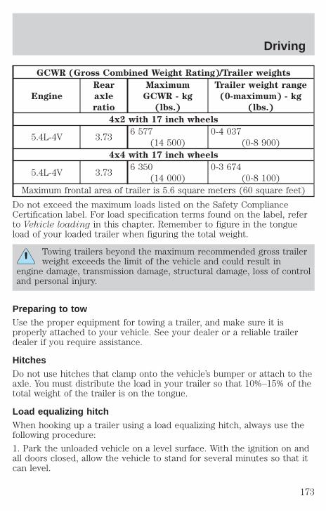
GCWR (Gross Combined Weight Rating)/Trailer weights
Engine
Rear
axle
ratio
Maximum
GCWR - kg
(lbs.)
Trailer weight range
(0-maximum) - kg
(lbs.)
4x2 with 17 inch wheels
5.4L-4V 3.736 577
(14 500)0-4 037
(0-8 900)4x4 with 17 inch wheels
5.4L-4V 3.736 350
(14 000)0-3 674
(0-8 100)Maximum frontal area of trailer is 5.6 square meters (60 square feet)
Do not exceed the maximum loads listed on the Safety ComplianceCertification label. For load specification terms found on the label, referto Vehicle loading in this chapter. Remember to figure in the tongueload of your loaded trailer when figuring the total weight.
Towing trailers beyond the maximum recommended gross trailerweight exceeds the limit of the vehicle and could result in
engine damage, transmission damage, structural damage, loss of controland personal injury.
Preparing to towUse the proper equipment for towing a trailer, and make sure it isproperly attached to your vehicle. See your dealer or a reliable trailerdealer if you require assistance.
HitchesDo not use hitches that clamp onto the vehicle’s bumper or attach to theaxle. You must distribute the load in your trailer so that 10%–15% of thetotal weight of the trailer is on the tongue.
Load equalizing hitchWhen hooking up a trailer using a load equalizing hitch, always use thefollowing procedure:
1. Park the unloaded vehicle on a level surface. With the ignition on andall doors closed, allow the vehicle to stand for several minutes so that itcan level.
Driving
173

2. Turn the air suspension (if equipped) control to OFF.
3. Measure the height of a reference point on the front and rear bumpersat the center of the vehicle.
4. Attach the trailer to the vehicle and adjust the hitch equalizers so thatthe front bumper height is within 0–13 mm (0.5 in) of the referencepoint. After proper adjustment, the rear bumper should be no higherthan in Step 3.
5. Turn the air suspension (if equipped) control to ON.
Adjusting an equalizing hitch so the rear bumper of the vehicleis lower or higher than it was unloaded will defeat the function
of the load equalizing hitch and may cause unpredictable handling.
Safety chainsAlways connect the trailer’s safety chains to the frame or hook retainersof the vehicle hitch. To connect the trailer’s safety chains, cross thechains under the trailer tongue and allow slack for turning corners.
If you use a rental trailer, follow the instructions that the rental agencygives to you.
Do not attach safety chains to the bumper.
Trailer brakesElectric brakes and manual, automatic or surge-type trailer brakes are safeif installed properly and adjusted to the manufacturer’s specifications. Thetrailer brakes must meet local and Federal regulations.
Do not connect a trailer’s hydraulic brake system directly to yourvehicle’s brake system. Your vehicle may not have enough
braking power and your chances of having a collision greatly increase.
The braking system of the tow vehicle is rated for operation at theGVWR not GCWR.
Trailer lampsTrailer lamps are required on most towed vehicles. Make sure yourtrailer lamps conform to local and Federal regulations. See your dealer ortrailer rental agency for proper instructions and equipment for hookingup trailer lamps.
Driving
174
Driving while you towWhen towing a trailer:
• Ensure that you turn off your speed control. The speed control mayshut off automatically when you are towing on long, steep grades.
• Consult your local motor vehicle speed regulations for towing a trailer.
• Use a lower gear when towing up or down steep hills. This willeliminate excessive downshifting and upshifting for optimum fueleconomy and transmission cooling.
• Anticipate stops and brake gradually.
Exceeding the GCWR rating may cause internal transmissiondamage and void your warranty coverage.
Servicing after towingIf you tow a trailer for long distances, your vehicle will require morefrequent service intervals. Refer to your scheduled maintenance guide formore information.
Trailer towing tips• Practice turning, stopping and backing up before starting on a trip to
get the feel of the vehicle trailer combination. When turning, makewider turns so the trailer wheels will clear curbs and other obstacles.
• Allow more distance for stopping with a trailer attached.
• If you are driving down a long or steep hill, shift to a lower gear. Donot apply the brakes continuously, as they may overheat and becomeless effective.
• The trailer tongue weight should be 10% of the loaded trailer weight.
• After you have traveled 80 km (50 miles), thoroughly check yourhitch, electrical connections and trailer wheel lug nuts.
• When stopped in traffic for long periods of time in hot weather, placethe gearshift in P (Park) and increase idle speed. This aids enginecooling and air conditioner efficiency.
• Vehicles with trailers should not be parked on a grade. If you mustpark on a grade, place wheel chocks under the trailer’s wheels.
Driving
175
Launching or retrieving a boatWhen backing down a ramp during boat launching or retrieval:• do not allow the static water level to rise above the bottom edge of
the rear bumper and• do not allow waves to break higher than 15 cm (6 inches) above the
bottom edge of the rear bumper.
Exceeding these limits may allow water to enter critical vehiclecomponents, adversely affecting driveability, emissions, reliability andcausing internal transmission damage.
Replace the rear axle lubricant any time the axle has been submerged inwater. Rear axle lubricant quantities are not to be checked or changedunless a leak is suspected or repair required.
Disconnect the wiring to the trailer before backing the trailer into thewater. Reconnect the wiring to the trailer after the trailer is removedfrom the water.
RECREATIONAL TOWING (ALL WHEELS ON THE GROUND)An example of recreational towing would be towing your vehicle behind amotorhome. Follow these guidelines if you have the need for recreationaltowing your vehicle with all four wheels on the ground. These guidelinesare designed to ensure that your transmission is not damaged.
2WD vehicles (with automatic transmissions)
• Place the transmission in N (Neutral)• Maximum speed is 56 km (35 mph)• Maximum distance is 80 km (50 miles)
If a distance of 80 km (50 miles) or a speed of 56 km (35 mph) must beexceeded, the drive shaft will have to be removed before the vehicle istowed.
Ford recommends the driveshaft be removed/installed only by a qualifiedtechnician. See your local dealer for driveshaft removal/installation.
Improper removal/installation of the driveshaft can causetransmission fluid loss, damage to the driveshaft and internaltransmission components.
4WD vehicles electronic shift transfer case (with automatictransmissions)
4x4 vehicles with electronic shift on the fly cannot be towed with anywheels on the ground.
Driving
176
GETTING ROADSIDE ASSISTANCETo fully assist if you should have a vehicle concern, Ford Motor Companyoffers a complimentary roadside assistance program. This program isseparate from the New Vehicle Limited Warranty. The service is available:
• 24–hours, seven days a week
• for the Basic warranty period (Canada) or New Vehicle LimitedWarranty period (U.S.) of three years or 60 000 km (36 000 miles),whichever comes first on Ford and Mercury vehicles, and four years or80 000 km (50 000 miles) on Lincoln vehicles
Roadside assistance will cover:
• changing a flat tire
• jump-starts
• lock-out assistance
• limited fuel delivery*
• towing of your disabled vehicle to the nearest Ford Motor Companydealership, or your selling dealer if within 25 kms (15.5 miles) of thenearest Ford Motor Company dealership (one tow per disablement).Even non-warranty related tows, like accidents or getting stuck in themud or snow, are covered (some exclusions apply, such as impoundtowing or repossession).
* Canadian customers refer to your Roadside Assistance supplementfor exact fuel amounts.
USING ROADSIDE ASSISTANCEComplete the roadside assistance identification card and place it in yourwallet for quick reference. In the United States, this card is found in theOwner Guide portfolio in the glove compartment in Ford vehicles and ismailed to you if you own a Mercury or Lincoln. In Canada, the card isfound in the Roadside Assistance book in the glove compartment.
U.S. Ford or Mercury vehicle customers who require roadside assistance,call 1–800–241–3673; Lincoln vehicle customers call 1–800–521–4140.
Canadian customers who require roadside assistance, call1–800–665–2006.
Roadside emergencies
177
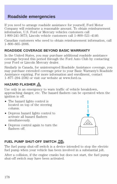
If you need to arrange roadside assistance for yourself, Ford MotorCompany will reimburse a reasonable amount. To obtain reimbursementinformation, U.S. Ford or Mercury vehicles customers call1-800-241-3673; Lincoln vehicle customers call 1–800–521–4140.
Canadian customers who need to obtain reimbursement information, call1–800–665–2006.
ROADSIDE COVERAGE BEYOND BASIC WARRANTYIn the United States, you may purchase additional roadside assistancecoverage beyond this period through the Ford Auto Club by contactingyour Ford or Lincoln Mercury dealer.
Similarly in Canada, for uninterrupted Roadside Assistance coverage, youmay purchase extended coverage prior to your Basic Warranty’s RoadsideAssistance expiring. For more information and enrollment, contact1–877–294–2582 or visit our website at www.ford.ca.
HAZARD FLASHERUse only in an emergency to warn traffic of vehicle breakdown,approaching danger, etc. The hazard flashers can be operated when theignition is off.
• The hazard lights control islocated on top of the steeringcolumn.
• Depress hazard lights control toactivate all hazard flasherssimultaneously.
• Depress control again to turn theflashers off.
FUEL PUMP SHUT-OFF SWITCH FUELRESET
The fuel pump shut-off switch is a device intended to stop the electricfuel pump when your vehicle has been involved in a substantial jolt.
After a collision, if the engine cranks but does not start, the fuel pumpshut-off switch may have been activated.
Roadside emergencies
178
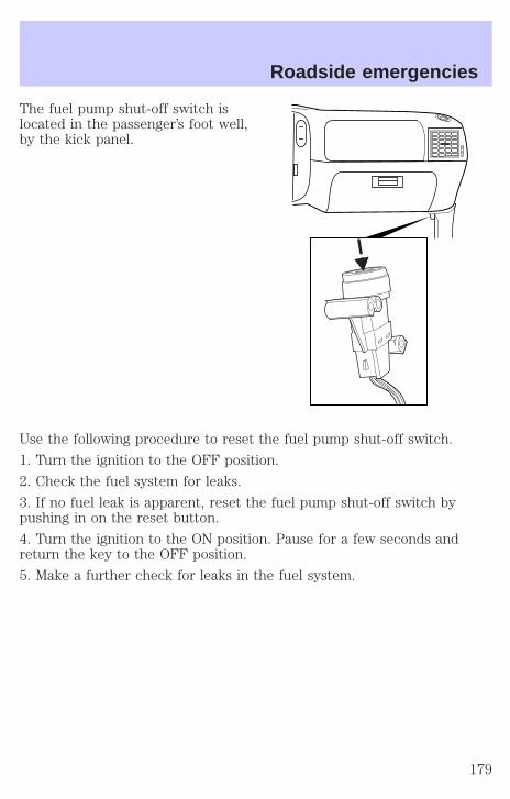
The fuel pump shut-off switch islocated in the passenger’s foot well,by the kick panel.
Use the following procedure to reset the fuel pump shut-off switch.
1. Turn the ignition to the OFF position.
2. Check the fuel system for leaks.
3. If no fuel leak is apparent, reset the fuel pump shut-off switch bypushing in on the reset button.
4. Turn the ignition to the ON position. Pause for a few seconds andreturn the key to the OFF position.
5. Make a further check for leaks in the fuel system.
Roadside emergencies
179

FUSES AND RELAYS
FusesIf electrical components in thevehicle are not working, a fuse mayhave blown. Blown fuses areidentified by a broken wire withinthe fuse. Check the appropriatefuses before replacing any electricalcomponents.
Note: Always replace a fuse with one that has the specified amperagerating. Using a fuse with a higher amperage rating can cause severe wiredamage and could start a fire.
Standard fuse amperage rating and color
COLOR
Fuse
rating
Mini
fuses
Standard
fuses
Maxi
fuses
Cartridge
maxi
fuses
Fuse link
cartridge
2A Grey Grey — — —3A Violet Violet — — —4A Pink Pink — — —5A Tan Tan — — —
7.5A Brown Brown — — —10A Red Red — — —15A Blue Blue — — —20A Yellow Yellow Yellow Blue Blue25A Natural Natural — — —30A Green Green Green Pink Pink40A — — Orange Green Green50A — — Red Red Red60A — — Blue — Yellow70A — — Tan — Brown80A — — Natural — Black
15
Roadside emergencies
180

Passenger compartment fuse panelThe fuse panel is located below and to the left of the steering wheel bythe brake pedal. Remove the panel cover to access the fuses.
To remove a fuse use the fuse puller tool provided on the fuse panelcover.
The fuses are coded as follows.
Fuse/Relay
Location
Fuse Amp
Rating
Passenger Compartment Fuse
Panel Description
1 25A Audio2 5A Clock, Overhead Trip Computer,
Electronic AutomaticTemperature Control (EATC),Powertrain Control Module(PCM), Cluster, Navigation
3 20A Cigar Lighter, OBD-II Scan ToolConnector
FUS
E1
1222
213
23
617
27
718
28
819
29
930
20
3121
1110R
ELA
Y5
RE
LAY
4
RE
LAY
3
RE
LAY
2
RE
LAY
1
314
24
415
25
516
26
Roadside emergencies
181

Fuse/Relay
Location
Fuse Amp
Rating
Passenger Compartment Fuse
Panel Description
4 7.5A Remote Entry Module, Mirrors,Memory Module, AdjustablePedals, Drivers Seat, Power FoldMirrors
5 15A Speed Control Module, ReverseLamp, Daytime Running LampRelay, Reverse Sensing System,Autolock, E/C Mirror, Navigation
6 5A Cluster, Overhead Trip Computer,Compass, Steering Sensor, BrakeShift Interlock Solenoid, AirSuspension Module, GEM Module,Heated Mirror, Rear Defroster,Reverse Sensing System,Automatic Park Brake Release
7 5A Aux A/C Blower Relay, ConsoleBlower
8 5A Remote Entry Module, CellPhone, Clock, GEM Module,Navigation
9 — Not Used10 — Not Used11 30A Front Washer Pump Relay, Wiper
Run/Park Relay, Wiper Hi/LORelay, Windshield Wiper Motor,Rear Washer Pump Relay
12 15A Air Suspension Switch13 20A Stop Lamp Switch (Lamps),
Turn/Hazard Flasher, SpeedControl Module
Roadside emergencies
182
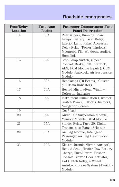
Fuse/Relay
Location
Fuse Amp
Rating
Passenger Compartment Fuse
Panel Description
14 15A Rear Wipers, Running BoardLamps, Battery Saver Relay,Interior Lamp Relay, AccessoryDelay Relay (Power Windows,Moonroof, Flip Windows, Audio),Homelink
15 5A Stop Lamp Switch, (SpeedControl, Brake Shift Interlock,ABS, PCM Module Inputs), GEMModule, Autolock, Air SuspensionModule
16 20A Headlamps (Hi Beams), Cluster(Hi Beam Indicator)
17 10A Heated Mirrors/Rear WindowDefroster Indicator
18 5A Instrument Illumination (DimmerSwitch Power), Clock (Dimmer),Navigation Screen
19 — Not Used20 5A Audio, Air Suspension Module,
Memory Module, GEM Module21 15A Starter Relay, Fuse 20, Digital
Transmission Range Selector22 10A Air Bag Module, Intelligent
Passenger Air Bag DeactivationModule
23 10A Electrochromic Mirror, Aux A/C,Heated Seats, Trailer Tow BatteryCharge, Turn/Hazard Flasher,Console Blower Door Actuator,4x4 Clutch Relay, 4 WheelAnti-Lock Brake System (4WABS)Module
Roadside emergencies
183
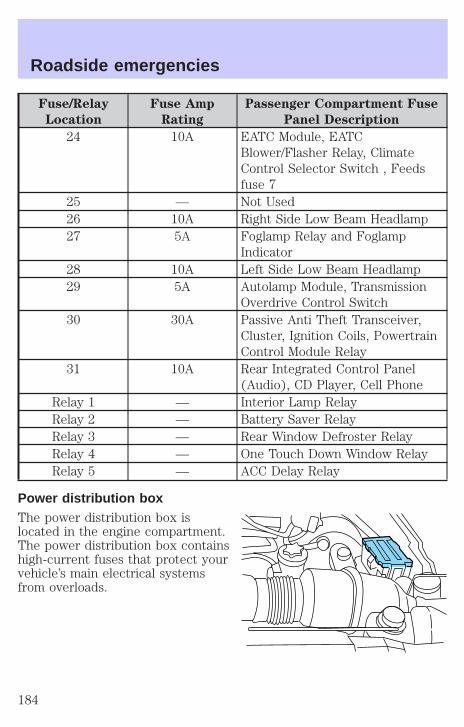
Fuse/Relay
Location
Fuse Amp
Rating
Passenger Compartment Fuse
Panel Description
24 10A EATC Module, EATCBlower/Flasher Relay, ClimateControl Selector Switch , Feedsfuse 7
25 — Not Used26 10A Right Side Low Beam Headlamp27 5A Foglamp Relay and Foglamp
Indicator28 10A Left Side Low Beam Headlamp29 5A Autolamp Module, Transmission
Overdrive Control Switch30 30A Passive Anti Theft Transceiver,
Cluster, Ignition Coils, PowertrainControl Module Relay
31 10A Rear Integrated Control Panel(Audio), CD Player, Cell Phone
Relay 1 — Interior Lamp RelayRelay 2 — Battery Saver RelayRelay 3 — Rear Window Defroster RelayRelay 4 — One Touch Down Window RelayRelay 5 — ACC Delay Relay
Power distribution boxThe power distribution box islocated in the engine compartment.The power distribution box containshigh-current fuses that protect yourvehicle’s main electrical systemsfrom overloads.
Roadside emergencies
184
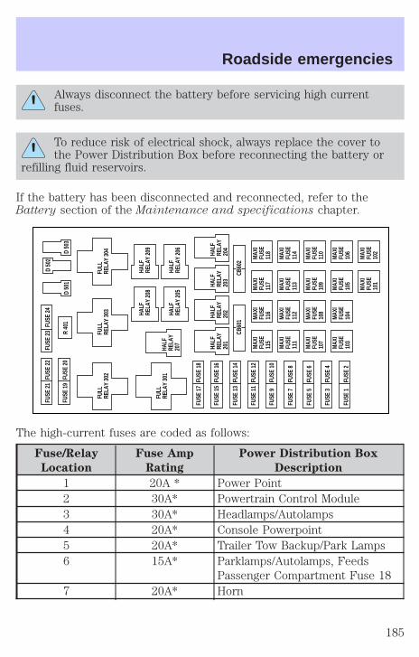
Always disconnect the battery before servicing high currentfuses.
To reduce risk of electrical shock, always replace the cover tothe Power Distribution Box before reconnecting the battery or
refilling fluid reservoirs.
If the battery has been disconnected and reconnected, refer to theBattery section of the Maintenance and specifications chapter.
The high-current fuses are coded as follows:
Fuse/Relay
Location
Fuse Amp
Rating
Power Distribution Box
Description
1 20A * Power Point2 30A* Powertrain Control Module3 30A* Headlamps/Autolamps4 20A* Console Powerpoint5 20A* Trailer Tow Backup/Park Lamps6 15A* Parklamps/Autolamps, Feeds
Passenger Compartment Fuse 187 20A* Horn
MAX
IFU
SE11
5
MAX
IFU
SE11
6
MAX
IFU
SE11
7
MAX
IFU
SE11
8
MAX
IFU
SE11
1
MAX
IFU
SE11
2
MAX
IFU
SE11
3
MAX
IFU
SE11
4
MAX
IFU
SE10
7
MAX
IFU
SE10
8
MAX
IFU
SE10
9
MAX
IFU
SE11
0
MAX
IFU
SE10
3
MAX
IFU
SE10
4
MAX
IFU
SE10
5
MAX
IFU
SE10
6
MAX
IFU
SE10
1
MAX
IFU
SE10
2
CB60
1CB
602
FUSE
17
FUSE
18
FUSE
21
FUSE
22
FUSE
19
FUSE
20
FUSE
23
FULL
RELA
Y 30
2
R 40
1D
501
FUSE
24
FUSE
15
FUSE
16
FUSE
13
FUSE
14
FUSE
11
FUSE
12
FUSE
9FU
SE 1
0
FUSE
7FU
SE 8
FUSE
5FU
SE 6
FUSE
3FU
SE 4
FUSE
1FU
SE 2
D 50
3
D 50
2
FULL
RELA
Y 30
1HA
LFRE
LAY
207
FULL
RELA
Y 30
3FU
LLRE
LAY
304
HALF
RELA
Y20
1
HALF
RELA
Y20
2HALF
RELA
Y 20
8HA
LFRE
LAY
209
HALF
RELA
Y 20
5HA
LFRE
LAY
206
HALF
RELA
Y20
3
HALF
RELA
Y20
4
Roadside emergencies
185
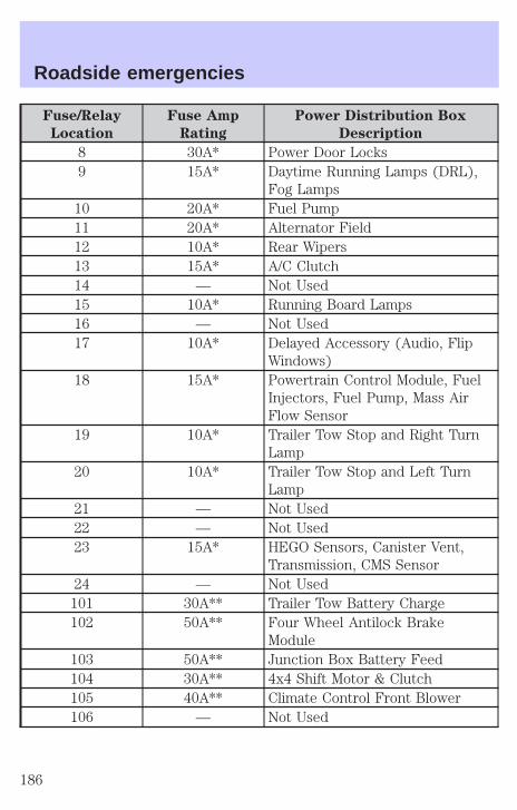
Fuse/Relay
Location
Fuse Amp
Rating
Power Distribution Box
Description
8 30A* Power Door Locks9 15A* Daytime Running Lamps (DRL),
Fog Lamps10 20A* Fuel Pump11 20A* Alternator Field12 10A* Rear Wipers13 15A* A/C Clutch14 — Not Used15 10A* Running Board Lamps16 — Not Used17 10A* Delayed Accessory (Audio, Flip
Windows)18 15A* Powertrain Control Module, Fuel
Injectors, Fuel Pump, Mass AirFlow Sensor
19 10A* Trailer Tow Stop and Right TurnLamp
20 10A* Trailer Tow Stop and Left TurnLamp
21 — Not Used22 — Not Used23 15A* HEGO Sensors, Canister Vent,
Transmission, CMS Sensor24 — Not Used
101 30A** Trailer Tow Battery Charge102 50A** Four Wheel Antilock Brake
Module103 50A** Junction Box Battery Feed104 30A** 4x4 Shift Motor & Clutch105 40A** Climate Control Front Blower106 — Not Used
Roadside emergencies
186
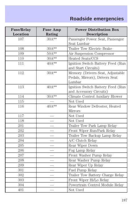
Fuse/Relay
Location
Fuse Amp
Rating
Power Distribution Box
Description
107 30A** Passenger Power Seat, PassengerSeat Lumbar
108 30A** Trailer Tow Electric Brake109 50A** Air Suspension Compressor110 30A** Heated Seats/CCS111 40A** Ignition Switch Battery Feed (Run
and Start Circuits)112 30A** Memory (Drivers Seat, Adjustable
Pedals, Mirrors), Drivers SeatLumbar
113 40A** Ignition Switch Battery Feed (Runand Accessory Circuits)
114 30A** Climate Control Auxilary Blower115 — Not Used116 40A** Rear Window Defroster, Heated
Mirrors117 — Not Used118 — Not Used201 — Trailer Tow Park Lamp Relay202 — Front Wiper Run/Park Relay203 — Trailer Tow Backup Lamp Relay204 — A/C Clutch Relay205 — Rear Wiper Down206 — Fog Lamp Relay207 — Front Washer Pump Relay208 — Rear Washer Pump Relay209 — Rear Wiper Up Relay301 — Fuel Pump Relay302 — Trailer Tow Battery Charge Relay303 — Front Wiper Hi/Lo Relay304 — Powertrain Control Module Relay401 — Not Used
Roadside emergencies
187
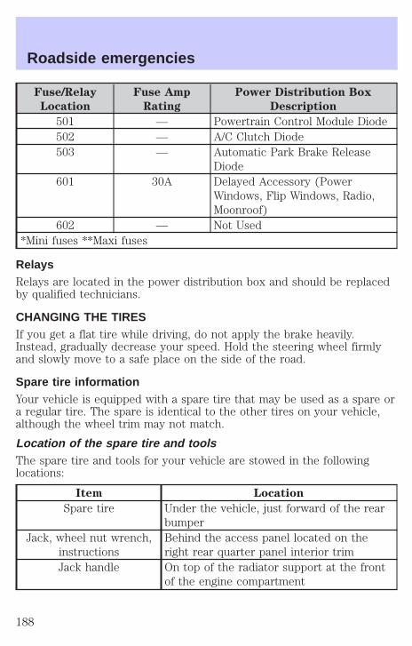
Fuse/Relay
Location
Fuse Amp
Rating
Power Distribution Box
Description
501 — Powertrain Control Module Diode502 — A/C Clutch Diode503 — Automatic Park Brake Release
Diode601 30A Delayed Accessory (Power
Windows, Flip Windows, Radio,Moonroof)
602 — Not Used*Mini fuses **Maxi fuses
RelaysRelays are located in the power distribution box and should be replacedby qualified technicians.
CHANGING THE TIRESIf you get a flat tire while driving, do not apply the brake heavily.Instead, gradually decrease your speed. Hold the steering wheel firmlyand slowly move to a safe place on the side of the road.
Spare tire informationYour vehicle is equipped with a spare tire that may be used as a spare ora regular tire. The spare is identical to the other tires on your vehicle,although the wheel trim may not match.
Location of the spare tire and toolsThe spare tire and tools for your vehicle are stowed in the followinglocations:
Item Location
Spare tire Under the vehicle, just forward of the rearbumper
Jack, wheel nut wrench,instructions
Behind the access panel located on theright rear quarter panel interior trim
Jack handle On top of the radiator support at the frontof the engine compartment
Roadside emergencies
188

Removing the jack handle1. Open the hood.
2. Unsnap the end of the handle that is retained by the clip on the top ofthe windshield washer bottle.
3. Unsnap the shaft of the handle from the two retaining clips attachedto the top of the radiator shroud.
Removing the jack and tools1. Locate the access panel on the right rear quarter panel interior trim.Lift the two panel retaining clips and remove the panel.
2. Unsnap the wheel lug nut wrench and instructions from their retainingbracket.
3. Remove the jack by turning the thumbwheel counterclockwise torelieve tension against the stowage bracket.
4. If equipped with a two piece lug wrench, assemble the lug wrench asshown in the illustration.
• To assemble, screw the partstogether. To disassemble,unscrew.
Removing the spare tire1. Open the liftgate.
2. Insert the straight end of the jackhandle into the rear access holelocated just above the rear bumper.
Forward motion will stop andresistance to turning will be feltwhen properly engaged.
3. Turn the handle counterclockwiseuntil tire is lowered to the groundand the cable is slightly slack.
4. Remove the retainer from the spare tire.
Roadside emergencies
189
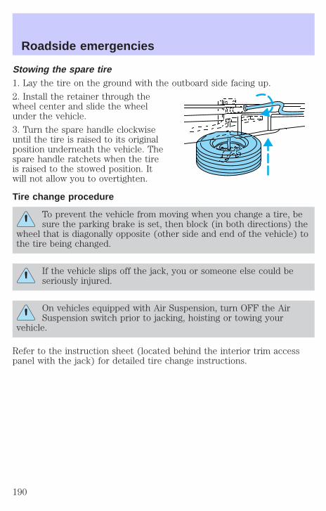
Stowing the spare tire1. Lay the tire on the ground with the outboard side facing up.
2. Install the retainer through thewheel center and slide the wheelunder the vehicle.
3. Turn the spare handle clockwiseuntil the tire is raised to its originalposition underneath the vehicle. Thespare handle ratchets when the tireis raised to the stowed position. Itwill not allow you to overtighten.
Tire change procedure
To prevent the vehicle from moving when you change a tire, besure the parking brake is set, then block (in both directions) the
wheel that is diagonally opposite (other side and end of the vehicle) tothe tire being changed.
If the vehicle slips off the jack, you or someone else could beseriously injured.
On vehicles equipped with Air Suspension, turn OFF the AirSuspension switch prior to jacking, hoisting or towing your
vehicle.
Refer to the instruction sheet (located behind the interior trim accesspanel with the jack) for detailed tire change instructions.
Roadside emergencies
190
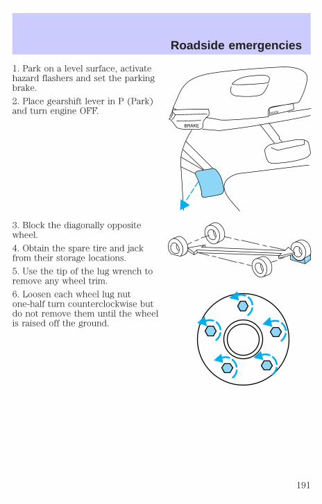
1. Park on a level surface, activatehazard flashers and set the parkingbrake.
2. Place gearshift lever in P (Park)and turn engine OFF.
3. Block the diagonally oppositewheel.
4. Obtain the spare tire and jackfrom their storage locations.
5. Use the tip of the lug wrench toremove any wheel trim.
6. Loosen each wheel lug nutone-half turn counterclockwise butdo not remove them until the wheelis raised off the ground.
Roadside emergencies
191
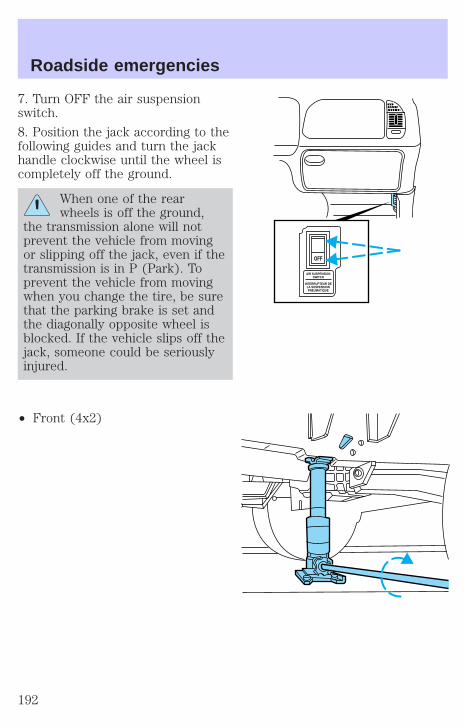
7. Turn OFF the air suspensionswitch.
8. Position the jack according to thefollowing guides and turn the jackhandle clockwise until the wheel iscompletely off the ground.
When one of the rearwheels is off the ground,
the transmission alone will notprevent the vehicle from movingor slipping off the jack, even if thetransmission is in P (Park). Toprevent the vehicle from movingwhen you change the tire, be surethat the parking brake is set andthe diagonally opposite wheel isblocked. If the vehicle slips off thejack, someone could be seriouslyinjured.
• Front (4x2)
AIR SUSPENSIONSWITCH
INTERRUPTEUR DELA SUSPENSIONPNEUMATIQUE
OFF
Roadside emergencies
192
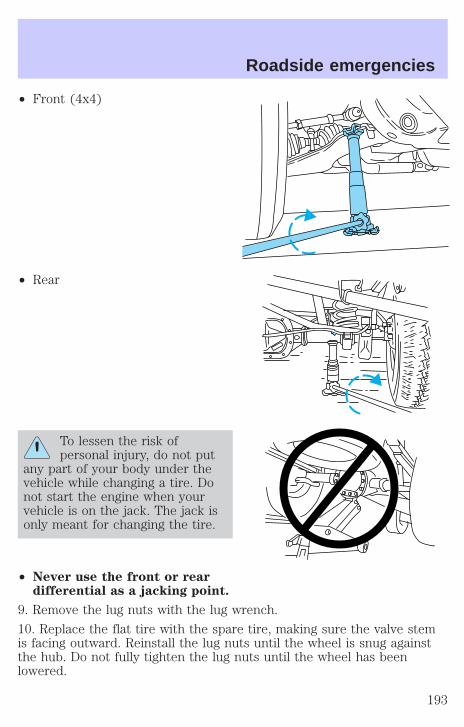
• Front (4x4)
• Rear
To lessen the risk ofpersonal injury, do not put
any part of your body under thevehicle while changing a tire. Donot start the engine when yourvehicle is on the jack. The jack isonly meant for changing the tire.
• Never use the front or reardifferential as a jacking point.
9. Remove the lug nuts with the lug wrench.
10. Replace the flat tire with the spare tire, making sure the valve stemis facing outward. Reinstall the lug nuts until the wheel is snug againstthe hub. Do not fully tighten the lug nuts until the wheel has beenlowered.
Roadside emergencies
193

11. Lower the wheel by turning the jack handle counterclockwise.
12. Remove the jack and fullytighten the lug nuts in the ordershown.
13. Stow the flat tire. Refer toStowing the spare tire.
14. Stow the jack and lug wrench.Make sure the jack is fastened so itdoes not rattle when you drive.
15. Unblock the wheels.
16. Turn on the air suspension switch.
JUMP STARTING YOUR VEHICLE
The gases around the battery can explode if exposed to flames,sparks, or lit cigarettes. An explosion could result in injury or
vehicle damage.
Batteries contain sulfuric acid which can burn skin, eyes, andclothing, if contacted.
Do not attempt to push-start your vehicle. Automatictransmissions do not have push-start capability; also, thecatalytic conveter may become damaged.
Preparing your vehicleWhen the battery is disconnected or a new battery is installed, thetransmission must relearn its adaptive strategy. As a result of this, thetransmission may shift firmly. This operation is considered normal andwill not affect function or durability of the transmission. Over time, theadaptive learning process will fully update transmission operation to itsoptimum shift feel.
1. Use only a 12–volt supply to start your vehicle.
2. Do not disconnect the battery of the disabled vehicle as this coulddamage the vehicle’s electrical system.
1
43
25
Roadside emergencies
194

3. Park the booster vehicle close to the hood of the disabled vehiclemaking sure the two vehicles do not touch. Set the parking brake onboth vehicles and stay clear of the engine cooling fan and other movingparts.
4. Check all battery terminals and remove any excessive corrosion beforeyou attach the battery cables. Ensure that vent caps are tight and level.
5. Turn the heater fan on in both vehicles to protect any electricalsurges. Turn all other accessories off.
Connecting the jumper cables
1. Connect the positive (+) booster cable to the positive (+) terminal ofthe discharged battery.
Note: In the illustrations, lightning bolts are used to designate theassisting (boosting) battery.
2. Connect the other end of the positive (+) cable to the positive (+)terminal of the assisting battery.
+–
+–
+–
+–
Roadside emergencies
195
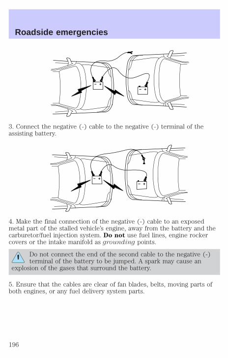
3. Connect the negative (-) cable to the negative (-) terminal of theassisting battery.
4. Make the final connection of the negative (-) cable to an exposedmetal part of the stalled vehicle’s engine, away from the battery and thecarburetor/fuel injection system. Do not use fuel lines, engine rockercovers or the intake manifold as grounding points.
Do not connect the end of the second cable to the negative (-)terminal of the battery to be jumped. A spark may cause an
explosion of the gases that surround the battery.
5. Ensure that the cables are clear of fan blades, belts, moving parts ofboth engines, or any fuel delivery system parts.
+–
+–
+–
+–
Roadside emergencies
196
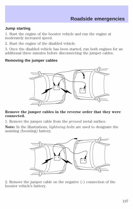
Jump starting1. Start the engine of the booster vehicle and run the engine atmoderately increased speed.
2. Start the engine of the disabled vehicle.
3. Once the disabled vehicle has been started, run both engines for anadditional three minutes before disconnecting the jumper cables.
Removing the jumper cables
Remove the jumper cables in the reverse order that they wereconnected.
1. Remove the jumper cable from the ground metal surface.
Note: In the illustrations, lightning bolts are used to designate theassisting (boosting) battery.
2. Remove the jumper cable on the negative (-) connection of thebooster vehicle’s battery.
+–
+–
+–
+–
Roadside emergencies
197
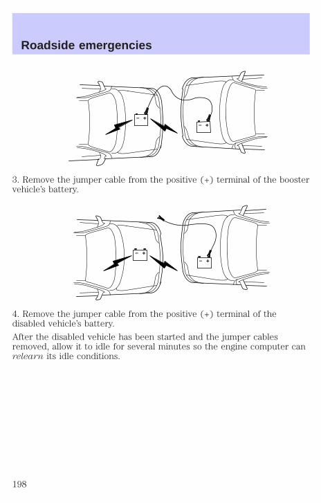
3. Remove the jumper cable from the positive (+) terminal of the boostervehicle’s battery.
4. Remove the jumper cable from the positive (+) terminal of thedisabled vehicle’s battery.
After the disabled vehicle has been started and the jumper cablesremoved, allow it to idle for several minutes so the engine computer canrelearn its idle conditions.
+–
+–
+–
+–
Roadside emergencies
198
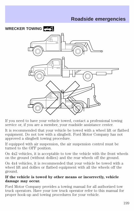
WRECKER TOWING
If you need to have your vehicle towed, contact a professional towingservice or, if you are a member, your roadside assistance center.
It is recommended that your vehicle be towed with a wheel lift or flatbedequipment. Do not tow with a slingbelt. Ford Motor Company has notapproved a slingbelt towing procedure.
If equipped with air suspension, the air suspension control must beturned to the OFF position.
On 4x2 vehicles, it is acceptable to tow the vehicle with the front wheelson the ground (without dollies) and the rear wheels off the ground.
On 4x4 vehicles, it is recommended that your vehicle be towed with awheel lift and dollies or flatbed equipment with all the wheels off theground.
If the vehicle is towed by other means or incorrectly, vehicledamage may occur.
Ford Motor Company provides a towing manual for all authorized towtruck operators. Have your tow truck operator refer to this manual forproper hook-up and towing procedures for your vehicle.
Roadside emergencies
199

GETTING THE SERVICES YOU NEED
At homeFord Motor Company and Ford of Canada have authorized dealerships toservice your vehicle. It is preferred that you return to the Ford dealerwhere your vehicle was purchased when warranty repairs are needed.However, you may also take your vehicle to another Ford MotorCompany or Ford of Canada dealership authorized for warranty repairs.Certain warranty repairs require special training though, so not alldealers are authorized to perform all warranty repairs. That means thatdepending on the warranty repair needed, the vehicle may need to betaken to another dealer. If a particular dealership can not assist you,then contact the Customer Relationship Center.
If you have questions or concerns, or are unsatisfied with the service youare receiving, follow these steps:
1. Contact your Sales Representative or Service Advisor at yourselling/servicing dealership.
2. If your inquiry or concern remains unresolved, contact the SalesManager or Service Manager at the dealership.
3. If the inquiry or concern cannot be resolved at the dealership level,please contact the Ford Customer Relationship Center.
Away from homeIf you own a Ford or Mercury vehicle and are away from home whenyour vehicle needs service, or if you need more help than the dealershipcould provide, after following the steps described above, contact theFord Customer Relationship Center to find an authorized dealership tohelp you. In the United States:
Ford Motor CompanyCustomer Relationship Center16800 Executive Plaza DriveP.O. Box 6248Dearborn, Michigan 481211-800-392-3673 (FORD)(TDD for the hearing impaired: 1-800-232-5952)
Customer assistance
200
In Canada:Customer Relationship CentreFord Motor Company of Canada, LimitedP.O. Box 2000Oakville, Ontario L6J 5E41-800-565-3673 (FORD)
If you own a Lincoln vehicle and are away from home when your vehicleneeds service, or if you need more help than the dealership couldprovide, after following the steps described above, contact the FordCustomer Relationship Center to find an authorized dealership to helpyou.
In the United States:Ford Motor CompanyCustomer Relationship Center16800 Executive Plaza DriveP.O. Box 6248Dearborn, Michigan 481211-800-521-4140(TDD for the hearing impaired: 1-800-232-5952)
In Canada:Customer Relationship CentreFord Motor Company of Canada, LimitedP.O. Box 2000Oakville, Ontario L6J 5E41-800-565-3673 (FORD)
In order to help you service your Ford or Lincoln Mercury vehicle, pleasehave the following information available when contacting a CustomerRelationship Center:
• Your telephone number (home and business).
• The name of the dealer and the city where the dealership is located.
• The year and make of your vehicle.
• The date of vehicle purchase.
• The current odometer reading.
• The vehicle identification number (VIN).
If you still have a complaint involving a warranty dispute, you may wishto contact the Dispute Settlement Board (U.S.).
Customer assistance
201
In some states (in the U.S.) you must directly notify Ford in writingbefore pursuing remedies under your state’s warranty laws. Ford is alsoallowed a final repair attempt in some states.
In the United States, a warranty dispute must be submitted to theDispute Settlement Board before taking action under the Magnuson-MossWarranty Act, or to the extent allowed by state law, before pursuingreplacement or repurchase remedies provided by certain state laws. Thisdispute handling procedure is not required prior to enforcing statecreated rights or other rights which are independent of theMagnuson-Moss Warranty Act or state replacement or repurchase laws.
FORD EXTENDED SERVICE PLANYou can get more protection for your new car or light truck bypurchasing Ford Extended Service Plan (Ford ESP) coverage. Ford ESPis an optional service contract which is backed by Ford Motor Companyor Ford Motor Service Company (in the U.S.) and Ford of Canada (inCanada). It provides the following:
• Benefits during the warranty period depending on the plan youpurchase (such as: reimbursement for rentals; coverage for certainmaintenance and wear items).
• Protection against covered repair costs after your Bumper-to-BumperWarranty expires.
You may purchase Ford ESP from any participating Ford and LincolnMercury and Ford of Canada dealer. There are several plans available invarious time, distance and deductible combinations which can be tailoredto fit your own driving needs. Ford ESP also offers reimbursementbenefits for towing and rental coverage.
When you buy Ford ESP, you receive Peace-of-Mind protectionthroughout the United States and Canada, provided by a network ofmore than 5,000 participating Ford or Lincoln Mercury and Ford ofCanada dealers.
If you did not take advantage of the Ford Extended Service Plan at thetime of purchasing your vehicle, you may still be eligible. Please contactyour dealer for further information. Since this information is subject tochange, please ask your dealer for complete details about Ford ExtendedService Plan coverage options, or visit the Ford ESP website atwww.ford-esp.com.
Customer assistance
202
THE DISPUTE SETTLEMENT BOARD (U.S. ONLY)The Dispute Settlement Board is:
• an independent, third-party arbitration program for warranty disputes
• available free to owners and lessees of qualifying Ford Motor Companyvehicles
The Dispute Settlement Board may not be available in all states. FordMotor Company reserves the right to change eligibility limitations, modifyprocedures and/or to discontinue this service without notice and withoutincurring obligations per applicable state law.
What kinds of cases does the Board review?Unresolved warranty repair concerns or vehicle performance concerns ason Ford and Lincoln Mercury cars and Ford and Lincoln Mercury lighttrucks which are within the terms of any applicable written new vehiclewarranty are eligible for review, except those involving:
• a non-Ford product
• a non-Ford dealership
• sales disputes between customer and dealer except those associatedwith warranty repairs or concerns with the vehicle’s performance asdesigned
• a request for reimbursement of consequential expenses unless aservice or product concern is being reviewed
• items not covered by the New Vehicle Limited Warranty (includingmaintenance and wear items)
• alleged personal injury/property damage claims
• cases currently in litigation
• vehicles not used primarily for family, personal or household purposes(except in states where the Dispute Settlement Board is required toreview commercial vehicles)
• vehicles with non-U.S. warranties
Concerns are ineligible for review if the New Vehicle Limited Warrantyhas expired at receipt of your application and, in certain states eligibilityis dependent upon the customer’s possession of the vehicle.
Eligibility may differ according to state law. For example, see the uniquebrochures for California, West Virginia, Georgia and Wisconsinpurchasers/lessees.
Customer assistance
203
Board membershipThe Board consists of:
• three consumer representatives
• a Ford or Lincoln Mercury dealership representative
Consumer candidates for Board membership are recruited and trained byan independent consulting firm. The dealership Board member is chosenfrom Ford and Lincoln Mercury dealership management, recognized fortheir business leadership qualities.
What the Board needsTo have your case reviewed you must complete the application in theDSB brochure and mail it to the address provided on the applicationform. Some states will require you to use certified mail, with returnreceipt requested.
Your application is reviewed and, if it is determined to be eligible, youwill receive an acknowledgment indicating:
• The file number assigned to your application.
• The toll-free phone number of the DSB’s independent administrator.
Your dealership and a Ford Motor Company representative will then beasked to submit statements.
To properly review your case, the Board needs the following information:
• Legible copies of all documents and maintenance or repair ordersrelevant to the case.
• The year, make, model, and Vehicle Identification Number (VIN) listedon your vehicle ownership license.
• The date of repair(s) and mileage at the time of occurrence(s).
• The current mileage.
• The name of the dealer(s) who sold or serviced the vehicle.
• A brief description of your unresolved concern.
• A brief summary of the action taken by the dealer(s) and Ford MotorCompany.
• The names (if known) of all the people you contacted at thedealership(s).
• A description of the action you expect to resolve your concern.
Customer assistance
204

You will receive a letter of explanation if your application does notqualify for Board review.
Oral presentationsIf you would like to make an oral presentation, indicate YES to question6 on the application. While it is your right to make an oral presentationbefore the Board, this is not a requirement and the Board will decide thecase whether or not an oral presentation is made. An oral presentationmay be requested by the Board as well.
Making a decisionBoard members review all available information related to eachcomplaint, including oral presentations, and arrive at a fair and impartialdecision. Board review may be terminated at any time by either party.
Every effort is made to decide the case within 40 days of the date thatall requested information is received by the Board. Since the Boardgenerally meets once a month, it may take longer for the Board toconsider some cases.
After a case is reviewed, the Board mails you a decision letter and aform on which to accept or reject the Board’s decision. The decisions ofthe Board are binding on Ford (and, in some cases, on the dealer) butnot on consumers who are free to pursue other remedies available tothem under state or federal law.
To Request a DSB Brochure/ApplicationFor a brochure/application, speak to your dealer or write/call to theBoard at the following address/phone number:
Dispute Settlement BoardP.O. Box 5120Southfield, MI 48086–51201–800–428–3718
You may also contact the North American Customer Relationship Centerat 1-800-392-3673 (Ford), TDD for the hearing impaired: 1-800-232-5952or by writing to the Center at the following address:
Ford Motor CompanyCustomer Relationship Center16800 Executive Plaza DriveP.O. Box 6248Dearborn, Michigan 48121
Customer assistance
205
UTILIZING THE MEDIATION/ARBITRATION PROGRAM(CANADA ONLY)In those cases where you continue to feel that the efforts by Ford andthe dealer to resolve a factory-related vehicle service concern have beenunsatisfactory, Ford of Canada participates in an impartial third partymediation/arbitration program administered by the Canadian MotorVehicle Arbitration Plan (CAMVAP).
The CAMVAP program is a straight-forward and relatively speedyalternative to resolve a disagreement when all other efforts to produce asettlement have failed. This procedure is without cost to you and isdesigned to eliminate the need for lengthy and expensive legalproceedings.
In the CAMVAP program, impartial third-party arbitrators conducthearings at mutually convenient times and places in an informalenvironment. These impartial arbitrators review the positions of theparties, make decisions and, when appropriate, render awards to resolvedisputes. CAMVAP decisions are fast, fair, and final; the arbitrator’saward is binding both to you and Ford of Canada.
CAMVAP services are available in all territories and provinces. For moreinformation, without charge or obligation, call your CAMVAP ProvincialAdministrator directly at 1-800-207-0685.
GETTING ASSISTANCE OUTSIDE THE U.S. AND CANADABefore exporting your vehicle to a foreign country, contact theappropriate foreign embassy or consulate. These officials can inform youof local vehicle registration regulations and where to find unleaded fuel.
If you cannot find unleaded fuel or can only get fuel with an anti-knockindex lower than is recommended for your vehicle, contact a district orowner relations/customer relationship office.
The use of leaded fuel in your vehicle without proper conversion maydamage the effectiveness of your emission control system and may causeengine knocking or serious engine damage. Ford Motor Company/Ford ofCanada is not responsible for any damage caused by use of improperfuel.
In the United States, using leaded fuel may also result in difficultyimporting your vehicle back into the U.S.
Customer assistance
206
If your vehicle must be serviced while you are traveling or living inCentral or South America, the Caribbean, or the Middle East, contact thenearest Ford dealership. If the dealership cannot help you, write or call:
FORD MOTOR COMPANYWORLDWIDE DIRECT MARKET OPERATIONS1555 Fairlane DriveFairlane Business Park #3Allen Park, Michigan 48101U.S.A.Telephone: (313) 594-4857FAX: (313) 390-0804
If you are in another foreign country, contact the nearest Forddealership. If the dealership employees cannot help you, they can directyou to the nearest Ford affiliate office.
If you buy your vehicle in North America and then relocate outside ofthe U.S. or Canada, register your vehicle identification number (VIN) andnew address with Ford Motor Company Worldwide Direct MarketOperations.
ORDERING ADDITIONAL OWNER’S LITERATURETo order the publications in this portfolio, contact Helm, Incorporated at:
HELM, INCORPORATEDP.O. Box 07150Detroit, Michigan 48207
Or call:
For a free publication catalog, order toll free: 1-800-782-4356
Monday-Friday 8:00 a.m. - 6:00 p.m. EST
(Items in this catalog may be purchased by credit card holders only.)
Customer assistance
207

Obtaining a French owner’s guideFrench Owner’s Guides can be obtained from your dealer or by writing toFord Motor Company of Canada, Limited, Service Publications, P.O. Box1580, Station B, Mississauga, Ontario L4Y 4G3.
IN CALIFORNIA (U.S. ONLY)California Civil Code Section 1793.2(d) requires that, if a manufactureror its representative is unable to repair a motor vehicle to conform to thevehicle’s applicable express warranty after a reasonable number ofattempts, the manufacturer shall be required to either replace thevehicle with one substantially identical or repurchase the vehicle andreimburse the buyer in an amount equal to the actual price paid orpayable by the consumer (less a reasonable allowance for consumeruse). The consumer has the right to choose whether to receive a refundor replacement vehicle.
California Civil Code Section 1793.22(b) presumes that the manufacturerhas had a reasonable number of attempts to conform the vehicle to itsapplicable express warranties if, within the first 18 months of ownershipof a new vehicle or the first 29 000 km (18 000 miles), whichever occursfirst:
1. Two or more repair attempts are made on the same nonconformitylikely to cause death or serious bodily injury OR
2. Four or more repair attempts are made on the same nonconformity (adefect or condition that substantially impairs the use, value or safety ofthe vehicle) OR
3. The vehicle is out of service for repair of nonconformities for a total ofmore than 30 calendar days (not necessarily all at one time)
In the case of 1 or 2 above, the consumer must also notify themanufacturer of the need for the repair of the nonconformity at thefollowing address:
16800 Executive Plaza DriveMail Drop 3NE-BDearborn, MI 48126
Customer assistance
208
REPORTING SAFETY DEFECTS (U.S. ONLY)If you believe that your vehicle hasa defect which could cause a crash,or could cause injury or death, youshould immediately inform theNational Highway Traffic SafetyAdministration (NHTSA) in additionto notifying Ford Motor Company.
If NHTSA receives similar complaints, it may open an investigation, andif it finds that a safety defect exists in a group of vehicles, it may order arecall and remedy campaign. However, NHTSA cannot become involvedin individual problems between you, your dealer or Ford Motor Company.
To contact NHTSA, you may either call the Auto Safety Hotline toll-freeat 1–800–424–9393 (202–366–0123 in the Washington D.C. area) or writeto:
NHTSAU.S. Department of Transportation400 Seventh StreetWashington, D.C. 20590
You can also obtain other information about motor vehicle safety fromthe Hotline.
Customer assistance
209
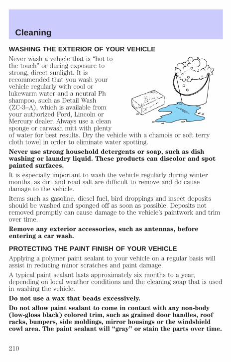
WASHING THE EXTERIOR OF YOUR VEHICLENever wash a vehicle that is “hot tothe touch” or during exposure tostrong, direct sunlight. It isrecommended that you wash yourvehicle regularly with cool orlukewarm water and a neutral Phshampoo, such as Detail Wash(ZC-3–A), which is available fromyour authorized Ford, Lincoln orMercury dealer. Always use a cleansponge or carwash mitt with plentyof water for best results. Dry the vehicle with a chamois or soft terrycloth towel in order to eliminate water spotting.
Never use strong household detergents or soap, such as dishwashing or laundry liquid. These products can discolor and spotpainted surfaces.
It is especially important to wash the vehicle regularly during wintermonths, as dirt and road salt are difficult to remove and do causedamage to the vehicle.
Items such as gasoline, diesel fuel, bird droppings and insect depositsshould be washed and sponged off as soon as possible. Deposits notremoved promptly can cause damage to the vehicle’s paintwork and trimover time.
Remove any exterior accessories, such as antennas, beforeentering a car wash.
PROTECTING THE PAINT FINISH OF YOUR VEHICLEApplying a polymer paint sealant to your vehicle on a regular basis willassist in reducing minor scratches and paint damage.
A typical paint sealant lasts approximately six months to a year,depending on local weather conditions and the cleaning soap that is usedin washing the vehicle.
Do not use a wax that beads excessively.
Do not allow paint sealant to come in contact with any non-body(low-gloss black) colored trim, such as grained door handles, roofracks, bumpers, side moldings, mirror housings or the windshieldcowl area. The paint sealant will “gray” or stain the parts over time.
Cleaning
210

REPAIRING PAINT CHIPSRemove particles such as bird droppings, tree sap, insect deposits, tarspots, road salt and industrial fallout before repairing paint chips.
Minor scratches or paint damage from road debris may be repaired usingthe Ultra Touch Prep and Finishing Kit (F7AZ-19K507–BA), which isavailable at your authorized Ford, Lincoln or Mercury dealer. This kitcontains:
• Lacquer Touch-Up Paint (ALBZ-19500–XXXXA)
• Exterior Acrylic Spray Lacquer (ALAZ-19500–XXXXA)
Please note that the part numbers (shown as XXXX above) will vary withyour vehicle’s specific coloring. Carefully observe the applicationinstructions on the products.
CLEANING THE WHEEL RIMS AND COVERSAluminum wheel rims or covers are coated with a clearcoat paintfinish.
Some automatic car washes may cause damage to the finish on yourwheel rims or covers. Chemical-strength cleaners, or cleaning chemicals,in combination with brush agitation to remove brake dust and dirt, couldwear away the clearcoat finish over time.
Do not use hydrofluoric acid-based or high caustic-based wheelcleaners, steel wool, fuels or strong household detergents forsoiled wheel rims and covers.
Never apply any cleaning chemical to hot or warm wheel rims or covers.
Clean wheel rims and covers with Detail Wash (ZC-3–A), which isavailable from your authorized Ford, Lincoln or Mercury dealer. Spraycleaner on cool wheel rims or covers and allow to set for 2–5 minutes.Agitate the area with a sponge and rinse off with plenty of water.
Use Extra Strength Tar and Road Oil Removal (B7A-19520–AA),available from your authorized Ford, Lincoln or Mercury dealer, in orderto remove tar and grease from wheel rims and covers.
CLEANING THE ENGINEEngines are more efficient when they are clean because grease and dirtbuildup keep the engine warmer than normal. When washing:
• The engine must be cool to the touch before spraying with water.
Cleaning
211

• Never spray a hot engine with cold water, as damage to theengine block or engine components may occur.
• Use caution when using a self-serve power washer (1000psi maximumpressure) to clean the engine, as the high-pressure fluid couldpenetrate the sealed parts and cause damage.
• Never apply anything to any exposed belts in the enginecompartment, including the belt dressing.
For general cleaning of the engine and engine compartment, sprayEngine Shampoo and Degreaser (F4AZ-19A536–A) on all parts thatrequire cleaning and pressure rinse the area with cool water.
• Cover the highlighted areas to prevent water damage when cleaningthe engine.
• Never wash or rinse the engine while it is running; water in therunning engine may cause internal damage.
WASHING NON-PAINTED PLASTIC EXTERIOR PARTSUse Detail Wash (ZC-3–A) for routine cleaning.
If tar or grease spots are present, clean with Extra Strength Tar andRoad Oil Removal (B7A-19520–AA).
Use only approved products to clean plastic parts. These productsare available from your authorized Ford, Lincoln or Mercury dealer.
WASHING THE EXTERIOR LAMPSIn order to avoid scratching the plastic lamps, do not use drypaper towels, non-approved chemical solvents or abrasivecleaners.
Cleaning
212
Use a soft cloth and a solution of Triple Clean (EOAZ-19526–AA), mixedproperly with water, in order to remove bug residue. If tar or greasespots are present, clean with Extra Strength Tar and Road Oil Removal(B7A-19520–AA).
CLEANING THE WINDSHIELD, WIPER BLADES AND REARWINDOWIf the wiper does not wipe properly, substances on the windshield, rearwindow or the wiper blades may be the cause. These may include hotwax treatments used by commercial car washes, tree sap, or otherorganic contamination.
Do not clean the windshield or rear window glass with abrasives,as they may cause scratches.
Do not use fuel, kerosene, or paint thinner to clean thewindshield, rear window or the wiper blades as damage mayoccur.
Clean the outside of the windshield or rear window with a non-abrasivecleaner such as Ultra Clear Spray Glass Cleaner (E4AZ-19C507–AA),available from your authorized Ford, Lincoln or Mercury dealer. If aftercleaning the glass surface, the water sheets from the glass (e.g., does notbead), then the window is clean.
The windshield, rear window and wiper blades should be cleanedregularly. Wiper blades can be cleaned with isopropyl (rubbing) alcoholor windshield washer solution. Be sure to replace wiper blades whenthey appear worn or do not function properly.
CLEANING THE INSTRUMENT PANELClean the instrument panel with a damp cloth, then dry with a dry cloth.
Avoid cleaners or polish that increase the gloss of the upper portion ofthe instrument panel. The dull finish in this area helps protect the driverfrom undesirable windshield reflection.
Do not use chemical solvents or strong detergents when cleaningthe steering wheel or instrument panel to avoid contamination of
the air bag system.
Cleaning
213
CLEANING THE INSTRUMENT CLUSTER LENSWipe the cluster area with a soft, damp cotton towel. Dry the area with aclean, dry towel.
CLEANING SEATS EQUIPPED WITH SIDE AIR BAGSRemove dust and loose dirt with a vacuum cleaner. In order to removestains and soil, clean with Extra Strength Upholstery Cleaner(E8AZ-19523–AA).
Never saturate the seat covers with any cleaning solution.
Do not use chemical solvents or strong detergents when cleaningthe seat where the side air bag is mounted. Such products could
contaminate the side air bag system and affect performance of the sideair bag in a collision. The air bag may not function correctly and notprovide injury reduction benefits.
CLEANING THE INTERIOR FABRIC, CARPETS AND CLOTH SEATSRemove dust and loose dirt with a vacuum cleaner. Remove light stainsand soil with Extra Strength Upholstery Cleaner (E8AZ-19523–AA).
Never saturate the seat covers with cleaning solution.
Do not use household cleaning products or glass cleaners, whichcan stain and discolor the fabric and affect the flame retardentabilities of the seat materials.
If grease or tar is present on the material, spot-clean the area first withSpot and Stain Remover (F3AZ-19521–WA). Follow up by recleaning thearea with Extra Strength Upholstery Cleaner (E8AZ-19523–AA).
CLEANING LEATHER SEATS (IF EQUIPPED)All Ford, Lincoln and Mercury vehicles with leather seating surfaces havea clear, protective coating over the leather.
To clean the leather seats, simply use a soft cloth with Deluxe Leatherand Vinyl Cleaner (F2AZ-19521–WA). Dry the area with a soft cloth.
Cleaning
214

It is recommended that you use the Deluxe Leather Care Kit(F8AZ-19G253–AA), available from your authorized Ford, Lincoln orMercury dealer. The mild cleaner and special pad available in the kitcleans the leather and maintains its natural beauty. For best results,follow the instructions printed on the cleaner label. Regular cleaning ofyour leather upholstery helps maintain its resiliency and color.
Do not use household cleaning products, alcohol solutions,solvents or cleaners intended for rubber, vinyl and plastics, oroil/petroleum-based leather conditioners. These products maycause premature wearing of the clear, protective coating.
CLEANING WOOD-TONE TRIMWipe stains with a clean, soft cloth and Ultra Clear Spray Glass Cleaner(E4AZ-19C507–AA). Dry the area by wiping with a dry, soft, clean cloth.
CLEANING THE INSIDE WINDOWSUse Ultra Clear Spray Glass Cleaner (E4AZ-19C507–AA) for the insidewindows if they become fogged.
To clean, use two lint-free, soft towels, folded into a pad-shape. Mist theglass completely with cleaner, and use one of the towels to evenly agitatethe surface. Use the other towel to remove the residue.
CLEANING THE CLIMATE CONTROL SEATS (IF EQUIPPED)Remove dust and loose dirt with a whisk broom or a vacuum cleaner.Remove fresh spots immediately. Clean the seat with a damp cloth, usinga mild soap and water solution, if necessary.
CLEANING AND MAINTAINING THE SAFETY BELTSClean the safety belts with Extra Strength Upholstery Cleaner(E8AZ-19523–AA), available from your authorized Ford, Lincoln orMercury dealer.
Do not use bleach, dye or any other solvent to clean the belts, asthese actions may weaken the belt webbing.
UNDERBODYFlush the complete underside of your vehicle frequently. Keep body anddoor drain holes free from packed dirt.
Cleaning
215
FORD, LINCOLN AND MERCURY CAR CARE PRODUCTSYour Ford, Lincoln or Mercury dealer has many quality products availableto clean your vehicle and protect its finishes. These quality productshave been specifically engineered to fulfill your automotive needs; theyare custom designed to complement the style and appearance of yourvehicle. Each product is made from high quality materials that meet orexceed rigid specifications. For best results, use the following orproducts of equivalent quality:
Ford Custom Clearcoat Polish*
Ford Custom Silicone Gloss Polish
Ford Custom Vinyl Protectant* (not available in Canada)
Motorcraft Vinyl Conditioner (Canada only)
Ford Deluxe Leather and Vinyl Cleaner (not available in Canada)
Motorcraft Vinyl Cleaner (Canada only)
Ford Extra Strength Tar and Road Oil Remover* (not available inCanada)
Ford Extra Strength Upholstery Cleaner (not available in Canada)
Ford Custom Bright Metal Cleaner
Motorcraft Premium Car Wash Concentrate
Motorcraft Carlite Glass Cleaner (Canada only)
Ford Spot and Stain Remover*
Ford Super Premium Tire and Trim Dressing
Ford Triple Clean
Ford Ultra-Clear Spray Glass Cleaner (not available in Canada)
Ford Engine Shampoo and Degreaser
* May be sold with the Motorcraft name
Cleaning
216

SERVICE RECOMMENDATIONSTo help you service your vehicle:
• We highlight do-it-yourself items in the engine compartment for easylocation.
• We provide a scheduled maintenance guide which makes trackingroutine service easy.
If your vehicle requires professional service, your dealership can providethe necessary parts and service. Check your Warranty Guide to find outwhich parts and services are covered.
Use only recommended fuels, lubricants, fluids and service partsconforming to specifications. Motorcraft parts are designed and built toprovide the best performance in your vehicle.
PRECAUTIONS WHEN SERVICING YOUR VEHICLEBe especially careful when inspecting or servicing your vehicle.
• Do not work on a hot engine.
• When the engine is running, make sure that loose clothing, jewelry orlong hair does not get caught up in moving parts.
• Do not work on a vehicle with the engine running in an enclosedspace, unless you are sure you have enough ventilation.
• Keep all lit cigarettes, open flames and other lit material away fromthe battery and all fuel related parts.
If you disconnect the battery, the engine must “relearn” its idleconditions before your vehicle will drive properly, as explained in Batteryin this chapter.
Maintenance and specifications
217
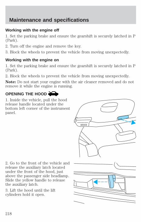
Working with the engine off1. Set the parking brake and ensure the gearshift is securely latched in P(Park).
2. Turn off the engine and remove the key.
3. Block the wheels to prevent the vehicle from moving unexpectedly.
Working with the engine on1. Set the parking brake and ensure the gearshift is securely latched in P(Park).
2. Block the wheels to prevent the vehicle from moving unexpectedly.
Note: Do not start your engine with the air cleaner removed and do notremove it while the engine is running.
OPENING THE HOOD1. Inside the vehicle, pull the hoodrelease handle located under thebottom left corner of the instrumentpanel.
2. Go to the front of the vehicle andrelease the auxiliary latch locatedunder the front of the hood, justabove the passenger side headlamp.Slide the yellow handle to releasethe auxiliary latch.
3. Lift the hood until the liftcylinders hold it open.
BRAKE
HOOD
Maintenance and specifications
218
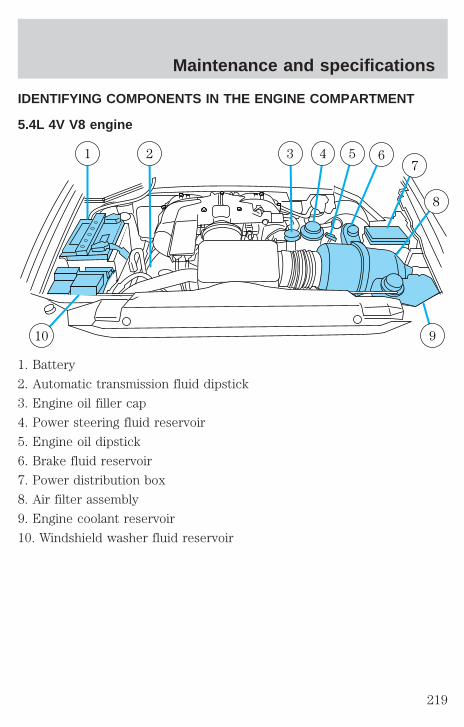
IDENTIFYING COMPONENTS IN THE ENGINE COMPARTMENT
5.4L 4V V8 engine
1. Battery
2. Automatic transmission fluid dipstick
3. Engine oil filler cap
4. Power steering fluid reservoir
5. Engine oil dipstick
6. Brake fluid reservoir
7. Power distribution box
8. Air filter assembly
9. Engine coolant reservoir
10. Windshield washer fluid reservoir
10 9
1 2 3 4 5 6
8
7
Maintenance and specifications
219

WINDSHIELD WASHER FLUID
Washer fluidCheck the washer fluid wheneveryou stop for fuel. The reservoir ishighlighted with a symbol.
If the level is low, add enough fluidto fill the reservoir. In very coldweather, do not fill the reservoir allthe way.
Only use a washer fluid that meets Ford specification ESR-M17P5–A.Refer to Lubricant specifications in this chapter.
State or local regulations on volatile organic compounds may restrict theuse of methanol, a common windshield washer antifreeze additive.Washer fluids containing non-methanol antifreeze agents should be usedonly if they provide cold weather protection without damaging thevehicle’s paint finish, wiper blades or washer system.
Note: Do not put washer fluid in the engine coolant reservoir. Washerfluid placed in the cooling system may harm engine and cooling systemcomponents.
Checking and adding washer fluid for the liftgateWasher fluid for the liftgate is supplied by the same reservoir as thewindshield.
ENGINE OIL
Checking the engine oilRefer to the scheduled maintenance guide for the appropriate intervalsfor checking the engine oil.
1. Make sure the vehicle is on level ground.
2. Turn the engine off and wait a few minutes for the oil to drain into theoil pan.
3. Set the parking brake and ensure the gearshift is securely latched in P(Park).
Maintenance and specifications
220
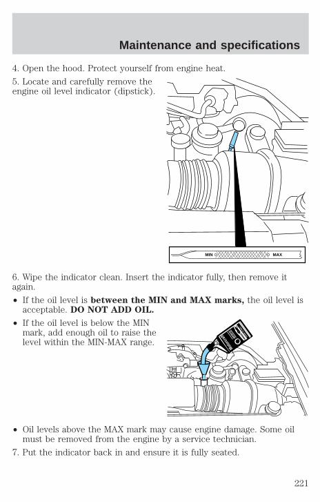
4. Open the hood. Protect yourself from engine heat.
5. Locate and carefully remove theengine oil level indicator (dipstick).
6. Wipe the indicator clean. Insert the indicator fully, then remove itagain.
• If the oil level is between the MIN and MAX marks, the oil level isacceptable. DO NOT ADD OIL.
• If the oil level is below the MINmark, add enough oil to raise thelevel within the MIN-MAX range.
• Oil levels above the MAX mark may cause engine damage. Some oilmust be removed from the engine by a service technician.
7. Put the indicator back in and ensure it is fully seated.
MAXMIN
Maintenance and specifications
221
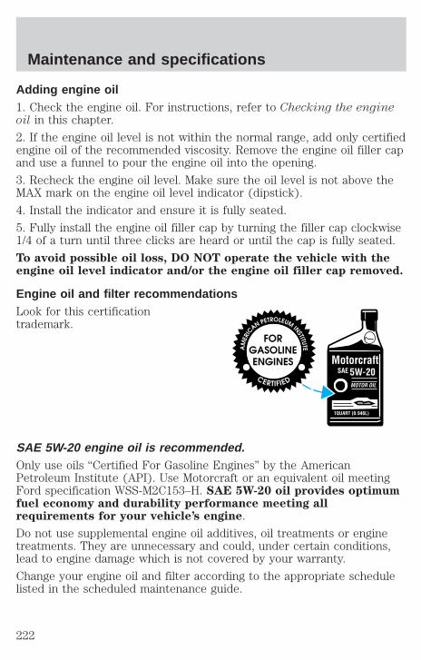
Adding engine oil1. Check the engine oil. For instructions, refer to Checking the engineoil in this chapter.
2. If the engine oil level is not within the normal range, add only certifiedengine oil of the recommended viscosity. Remove the engine oil filler capand use a funnel to pour the engine oil into the opening.
3. Recheck the engine oil level. Make sure the oil level is not above theMAX mark on the engine oil level indicator (dipstick).
4. Install the indicator and ensure it is fully seated.
5. Fully install the engine oil filler cap by turning the filler cap clockwise1/4 of a turn until three clicks are heard or until the cap is fully seated.
To avoid possible oil loss, DO NOT operate the vehicle with theengine oil level indicator and/or the engine oil filler cap removed.
Engine oil and filter recommendationsLook for this certificationtrademark.
SAE 5W-20 engine oil is recommended.Only use oils “Certified For Gasoline Engines” by the AmericanPetroleum Institute (API). Use Motorcraft or an equivalent oil meetingFord specification WSS-M2C153–H. SAE 5W-20 oil provides optimumfuel economy and durability performance meeting allrequirements for your vehicle’s engine.
Do not use supplemental engine oil additives, oil treatments or enginetreatments. They are unnecessary and could, under certain conditions,lead to engine damage which is not covered by your warranty.
Change your engine oil and filter according to the appropriate schedulelisted in the scheduled maintenance guide.
Maintenance and specifications
222
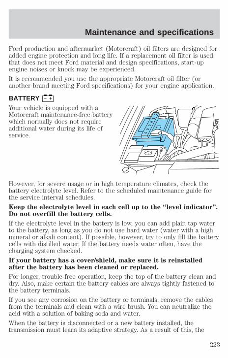
Ford production and aftermarket (Motorcraft) oil filters are designed foradded engine protection and long life. If a replacement oil filter is usedthat does not meet Ford material and design specifications, start-upengine noises or knock may be experienced.
It is recommended you use the appropriate Motorcraft oil filter (oranother brand meeting Ford specifications) for your engine application.
BATTERYYour vehicle is equipped with aMotorcraft maintenance-free batterywhich normally does not requireadditional water during its life ofservice.
However, for severe usage or in high temperature climates, check thebattery electrolyte level. Refer to the scheduled maintenance guide forthe service interval schedules.
Keep the electrolyte level in each cell up to the “level indicator”.Do not overfill the battery cells.
If the electrolyte level in the battery is low, you can add plain tap waterto the battery, as long as you do not use hard water (water with a highmineral or alkali content). If possible, however, try to only fill the batterycells with distilled water. If the battery needs water often, have thecharging system checked.
If your battery has a cover/shield, make sure it is reinstalledafter the battery has been cleaned or replaced.
For longer, trouble-free operation, keep the top of the battery clean anddry. Also, make certain the battery cables are always tightly fastened tothe battery terminals.
If you see any corrosion on the battery or terminals, remove the cablesfrom the terminals and clean with a wire brush. You can neutralize theacid with a solution of baking soda and water.
When the battery is disconnected or a new battery installed, thetransmission must learn its adaptive strategy. As a result of this, the
Maintenance and specifications
223

transmission may shift firmly. This operation is considered normal andwill fully update transmission operation to its optimum shift feel.
Batteries normally produce explosive gases which can causepersonal injury. Therefore, do not allow flames, sparks or lighted
substances to come near the battery. When working near the battery,always shield your face and protect your eyes. Always provide properventilation.
When lifting a plastic-cased battery, excessive pressure on theend walls could cause acid to flow through the vent caps,
resulting in personal injury and/or damage to the vehicle or battery.Lift the battery with a battery carrier or with your hands on oppositecorners.
Keep batteries out of reach of children. Batteries contain sulfuricacid. Avoid contact with skin, eyes or clothing. Shield your eyes
when working near the battery to protect against possible splashing ofacid solution. In case of acid contact with skin or eyes, flushimmediately with water for a minimum of 15 minutes and get promptmedical attention. If acid is swallowed, call a physician immediately.
Battery posts, terminals and related accessories contain lead andlead compunds. Wash hands after handling.
For information on transmission operation after the battery has beendisconnected see “Shift strategy” in the driving section.
Because your vehicle’s engine is electronically controlled by a computer,some control conditions are maintained by power from the battery. Whenthe battery is disconnected or a new battery is installed, the engine mustrelearn its idle and fuel trim strategy for optimum driveability andperformance. To begin this process:
1. With the vehicle at a complete stop, set the parking brake.
2. Put the gearshift in P (Park), turn off all accessories and start theengine.
3. Run the engine until it reaches normal operating temperature.
4. Allow the engine to idle for at least one minute.
Maintenance and specifications
224

5. Turn the A/C on and allow the engine to idle for at least one minute.
6. With your foot on the brake pedal and with the A/C on, put thevehicle in D (Drive) and allow the engine to idle for at least one minute.
7. Drive the vehicle to complete the relearning process.
• The vehicle may need to be driven 16 km (10 miles) or more torelearn the idle and fuel trim strategy.
• If you do not allow the engine to relearn its idle trim, the idlequality of your vehicle may be adversely affected until the idletrim is eventually relearned.
If the battery has been disconnected or a new battery has been installed,the clock must be reset once the battery is reconnected.
• Always dispose of automotivebatteries in a responsible manner.Follow your local authorizedstandards for disposal. Call yourlocal authorized recycling centerto find out more about recyclingautomotive batteries.
ENGINE COOLANT
Checking engine coolantThe concentration and level of engine coolant should be checked at themileage intervals listed in the scheduled maintenance guide. The coolantconcentration should be maintained at 50/50 coolant and water, whichequates to a freeze point of -36° C (-34° F). Coolant concentrationtesting is possible with a hydrometer or antifreeze tester (such as theRotunda Battery and Antifreeze Tester, 014–R1060). The level of coolantshould be maintained at the “cold full” of “cold fill range” level in thecoolant reservoir. If the level falls below, add coolant per the instructionsin the Adding Engine Coolant section.
LE
AD
RE
TU
RN
RECYCLE
Maintenance and specifications
225
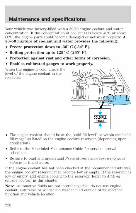
Your vehicle was factory-filled with a 50/50 engine coolant and waterconcentration. If the concentration of coolant falls below 40% or above60%, the engine parts could become damaged or not work properly. A50–50 mixture of coolant and water provides the following:
• Freeze protection down to -36° C (-34° F).
• Boiling protection up to 129° C (265° F).
• Protection against rust and other forms of corrosion.
• Enables calibrated gauges to work properly.
When the engine is cold, check thelevel of the engine coolant in thereservoir.
• The engine coolant should be at the “cold fill level” or within the “coldfill range” as listed on the engine coolant reservoir (depending uponapplication).
• Refer to the Scheduled Maintenance Guide for service intervalschedules.
• Be sure to read and understand Precautions when servicing yourvehicle in this chapter.
If the engine coolant has not been checked at the recommended interval,the engine coolant reservoir may become low or empty. If the reservoir islow or empty, add engine coolant to the reservoir. Refer to Addingengine coolant in this chapter.
Note: Automotive fluids are not interchangeable; do not use enginecoolant, antifreeze or windshield washer fluid outside of its specifiedfunction and vehicle location.
COLD FILLRANGE
Maintenance and specifications
226
Adding engine coolantWhen adding coolant, make sure it is a 50/50 mixture of engine coolantand distilled water. Add the mixture to the coolant reservoir, when theengine is cool, until the appropriate fill level is obtained.
Do not add engine coolant when the engine is hot. Steam andscalding liquids released from a hot cooling system can burn you
badly. Also, you can be burned if you spill coolant on hot engine parts.
Do not put engine coolant in the windshield washer fluidcontainer. If sprayed on the windshield, engine coolant could
make it difficult to see through the windshield.
The cooling system in your vehicle is filled with either green-coloredMotorcraft Premium Engine Coolant meeting Ford specificationESE-M97B44–A or yellow-colored Motorcraft Premium Gold EngineCoolant meeting Ford Specification WSS-M97B51–A1. To determine yourvehicle’s coolant type (color), check your coolant reservoir.
• Add Motorcraft Premium Engine Coolant (green-colored),VC-4–A (U.S.) or CXC-10 (Canada) or Motorcraft PremiumGold Engine Coolant (yellow-colored), VC-7–A, depending onthe type of coolant originally equipped in your vehicle. If youare unsure which type of coolant your vehicle requires, check yourcoolant reservoir or contact your local dealer.
• Do not add/mix an orange-colored, extended life coolant suchas Motorcraft Speciality Orange Engine Coolant, VC-2 (US) orCXC-209 (Canada), meeting Ford specification WSS-M97B44–Dwith the factory-filled coolant. Mixing Motorcraft Speciality OrangeEngine Coolant or any orange-colored extended life product with yourfactory filled coolant can result in degraded corrosion protection.
• A large amount of water without engine coolant may be added, in caseof emergency, to reach a vehicle service location. In this instance, thecooling system must be drained and refilled with a 50/50 mixture ofengine coolant and distilled water as soon as possible. Water alone(without engine coolant) can cause engine damage from corrosion,overheating or freezing.
Maintenance and specifications
227

• Do not use alcohol, methanol or brine or any engine coolantsmixed with alcohol or methanol antifreeze (coolant). Alcoholand other liquids can cause engine damage from overheating orfreezing.
• Do not add extra inhibitors or additives to the coolant. Thesecan be harmful and compromise the corrosion protection of the enginecoolant.
• Do not mix with recycled coolant unless from a Ford-approvedrecycling process (see Use of Recycled Engine Coolant section).
For vehicles with overflow coolant systems with a non-pressurized capon the coolant recovery system, add coolant to the coolant recoveryreservoir when the engine is cool. Add the proper mixture of coolant andwater to the “cold full” level. For all other vehicles, which have a coolantdegas system with a pressurized cap, or if it is necessary to remove thecoolant pressure relief cap on the radiator of a vehicle with an overflowsystem, follow these steps to add engine coolant.
To avoid personal injury, make sure the engine is cool beforeunscrewing the coolant pressure relief cap. The cooling system is
under pressure; steam and hot liquid can come out forcefully when thecap is loosened slightly.
1. Before you begin, turn the engine off and let it cool.
2. When the engine is cool, wrap a thick cloth around the coolantpressure relief cap on the coolant reservoir (an opaque plastic bottle).Slowly turn cap counterclockwise (left) until pressure begins to release.
3. Step back while the pressure releases.
4. When you are sure that all the pressure has been released, use thecloth to turn it counterclockwise and remove the cap.
5. Fill the coolant reservoir slowly with the proper coolant mixture (seeabove), to within the “cold fill range” or the “cold full” level on thereservoir. If you removed the radiator cap in an overflow system, fill theradiator until the coolant is visible and radiator is almost full.
6. Replace the cap. Turn until tightly installed. (Cap must be tightlyinstalled to prevent coolant loss.)
After any coolant has been added, check the coolant concentration seeChecking Engine Coolant section). If the concentration is not 50/50(protection to –34° F/–36° C), drain some coolant and adjust the
Maintenance and specifications
228
concentration. It may take several drains and additions to obtain a 50/50coolant concentration.
Whenever coolant has been added, the coolant level in the coolantreservoir should be checked the next few times you drive the vehicle. Ifnecessary, add enough 50/50 concentration of engine coolant anddistilled water to bring the liquid level to the proper level.
If you have to add more than 1.0 liter (1.0 quart) of engine coolant permonth, have your dealer check the engine cooling system. Your coolingsystem may have a leak. Operating an engine with a low level of coolantcan result in engine overheating and possible engine damage.
Recycled engine coolantFord Motor Company recommends the use of a recycled engine coolantproduced by Ford-approved processes in vehicles originally equippedwith Motorcraft Premium Engine Coolant (green-colored). However, notall coolant recycling processes produce coolant that meets Fordspecification ESE-M97B44–A. Use of such coolant may harm the engineand cooling system components.
Ford Motor Company does NOT recommend the use of recycled enginecoolant in vehicles originally equipped with Motorcraft Premium GoldEngine Coolant since a Ford-approved recycling process is not yetavailable.
Used engine coolant should be disposed of in an appropriatemanner. Follow your community’s regulations and standards for recyclingand disposing of automotive fluids.
Coolant refill capacityTo find out how much fluid your vehicle’s cooling system can hold, referto Refill capacities in this chapter.
Fill your engine coolant reservoir as outlined in Adding engine coolantin this chapter.
Maintenance and specifications
229
Severe climatesIf you drive in extremely cold climates (less than –36° C [–34° F]):
• It may be necessary to increase the coolant concentrationabove 50%.
• NEVER increase the coolant concentration above 60%.
• Increased engine coolant concentrations above 60% willdecrease the overheat protection characteristics of the enginecoolant and may cause engine damage.
• Refer to the chart on the coolant container to ensure thecoolant concentration in your vehicle will provide adequatefreeze protection at the temperatures in which you drive in thewinter months.
If you drive in extremely hot climates:
• It is still necessary to maintain the coolant concentrationabove 40%.
• NEVER decrease the coolant concentration below 40%.
• Decreased engine coolant concentrations below 40% willdecrease the corrosion protection characteristics of the enginecoolant and may cause engine damage.
• Decreased engine coolant concentrations below 40% willdecrease the freeze protection characteristics of the enginecoolant and may cause engine damage.
• Refer to the chart on the coolant container to ensure thecoolant concentration in your vehicle will provide adequateprotection at the temperatures in which you drive.
Vehicles driven year-round in non-extreme climates should use a 50/50mixture of engine coolant and distilled water for optimum cooling systemand engine protection.
What you should know about fail-safe coolingIf the engine coolant supply is depleted, this feature allows the vehicle tobe driven temporarily before incremental component damage is incurred.The “fail-safe” distance depends on ambient temperatures, vehicle loadand terrain.
Maintenance and specifications
230
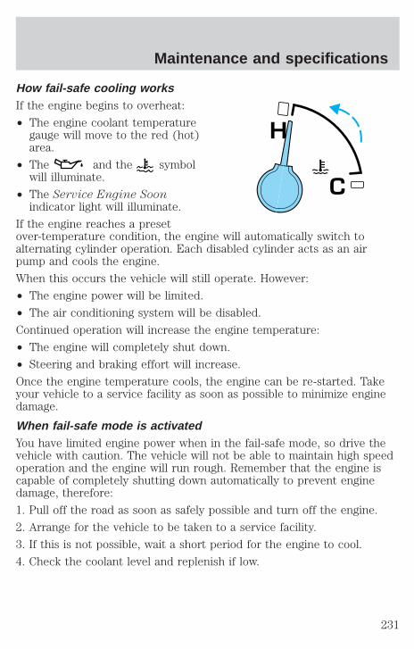
How fail-safe cooling worksIf the engine begins to overheat:
• The engine coolant temperaturegauge will move to the red (hot)area.
• The and the symbolwill illuminate.
• The Service Engine Soonindicator light will illuminate.
If the engine reaches a presetover-temperature condition, the engine will automatically switch toalternating cylinder operation. Each disabled cylinder acts as an airpump and cools the engine.
When this occurs the vehicle will still operate. However:
• The engine power will be limited.
• The air conditioning system will be disabled.
Continued operation will increase the engine temperature:
• The engine will completely shut down.
• Steering and braking effort will increase.
Once the engine temperature cools, the engine can be re-started. Takeyour vehicle to a service facility as soon as possible to minimize enginedamage.
When fail-safe mode is activatedYou have limited engine power when in the fail-safe mode, so drive thevehicle with caution. The vehicle will not be able to maintain high speedoperation and the engine will run rough. Remember that the engine iscapable of completely shutting down automatically to prevent enginedamage, therefore:
1. Pull off the road as soon as safely possible and turn off the engine.
2. Arrange for the vehicle to be taken to a service facility.
3. If this is not possible, wait a short period for the engine to cool.
4. Check the coolant level and replenish if low.
H
C
Maintenance and specifications
231
Never remove the coolant reservoir cap while the engine isrunning or hot.
5. Restart the engine and take your vehicle to a service facility.
Driving the vehicle without repairing the engine problemincreases the chance of engine damage. Take your vehicle to aservice facility as soon as possible.
WHAT YOU SHOULD KNOW ABOUT AUTOMOTIVE FUELS
Important safety precautions
Do not overfill the fuel tank. The pressure in an overfilled tankmay cause leakage and lead to fuel spray and fire.
The fuel system may be under pressure. If the fuel filler cap isventing vapor or if you hear a hissing sound, wait until it stops
before completely removing the fuel filler cap. Otherwise, fuel mayspray out and injure you or others.
If you do not use the proper fuel filler cap, excessive pressure orvacuum in the fuel tank may damage the fuel system or cause
the fuel cap to disengage in a collision, which may result in possiblepersonal injury.
Automotive fuels can cause serious injury or death if misused ormishandled.
Gasoline may contain benzene, which is a cancer-causing agent.
Maintenance and specifications
232
Observe the following guidelines when handling automotive fuel:
• Extinguish all smoking materialsand any open flames beforefueling your vehicle.
• Always turn off the vehicle beforefueling.
• Automotive fuels can be harmfulor fatal if swallowed. Fuel such asgasoline is highly toxic and ifswallowed can cause death orpermanent injury. If fuel isswallowed, call a physician immediately, even if no symptoms areimmediately apparent. The toxic effects of fuel may not be visible forhours.
• Avoid inhaling fuel vapors. Inhaling too much fuel vapor of any kindcan lead to eye and respiratory tract irritation. In severe cases,excessive or prolonged breathing of fuel vapor can cause seriousillness and permanent injury.
• Avoid getting fuel liquid in your eyes. If fuel is splashed in the eyes,remove contact lenses (if worn), flush with water for 15 minutes andseek medical attention. Failure to seek proper medical attention couldlead to permanent injury.
• Fuels can also be harmful if absorbed through the skin. If fuel issplashed on the skin and/or clothing, promptly remove contaminatedclothing and wash skin thoroughly with soap and water. Repeated orprolonged skin contact with fuel liquid or vapor causes skin irritation.
• Be particularly careful if you are taking “Antabuse” or other forms ofdisulfiram for the treatment of alcoholism. Breathing gasoline vapors,or skin contact could cause an adverse reaction. In sensitiveindividuals, serious personal injury or sickness may result. If fuel issplashed on the skin, promptly wash skin thoroughly with soap andwater. Consult a physician immediately if you experience an adversereaction.
When refueling always shut the engine off and never allowsparks or open flames near the filler neck. Never smoke while
refueling. Fuel vapor is extremely hazardous under certain conditions.Care should be taken to avoid inhaling excess fumes.
Maintenance and specifications
233
The flow of fuel through a fuel pump nozzle can produce staticelectricity, which can cause a fire if fuel is pumped into an
ungrounded fuel container.
Use the following guidelines to avoid static build-up when filling anungrounded fuel container:
• Place approved fuel container on the ground.
• DO NOT fill a fuel container while it is in the vehicle (including thecargo area).
• Keep the fuel pump nozzle in contact with the fuel container whilefilling.
• DO NOT use a device that would hold the fuel pump handle in the fillposition.
Fuel Filler CapYour fuel tank filler cap has an indexed design with a 1/8 turn on/offfeature.
When fueling your vehicle:
1. Turn the engine off.
2. Carefully turn the filler cap counterclockwise 1/8 of a turn until itstops.
3. Pull to remove the cap from the fuel filler pipe.
4. To install the cap, align the tabs on the cap with the notches on thefiller pipe.
5. Turn the filler cap clockwise 1/8 of a turn until it stops.
If the “Service Engine Soon/Check Engine” indicator comes on and stayson after you start the engine, the fuel filler cap may not be properlyinstalled. Turn off the engine, remove the fuel filler cap, align the capproperly and reinstall it.
If you must replace the fuel filler cap, replace it with a fuel fillercap that is designed for your vehicle. The customer warranty maybe void for any damage to the fuel tank or fuel system if thecorrect genuine Ford or Motorcraft fuel filler cap is not used.
Maintenance and specifications
234

The fuel system may be under pressure. If the fuel filler cap isventing vapor or if you hear a hissing sound, wait until it stops
before completely removing the fuel filler cap. Otherwise, fuel mayspray out and injure you or others.
If you do not use the proper fuel filler cap, excessive pressure orvacuum in the fuel tank may damage the fuel system or cause
the fuel cap to disengage in a collision, which may result in possiblepersonal injury.
Choosing the right fuelUse only UNLEADED FUEL. The use of leaded fuel is prohibited by lawand could damage your vehicle.
Do not use fuel containing methanol. It can damage critical fuel systemcomponents.
Your vehicle was not designed to use fuel or fuel additives with metalliccompounds, including manganese-based compounds containing MMT.
Repairs to correct the effects of using a fuel for which your vehicle wasnot designed may not be covered by your warranty.
Octane recommendationsYour vehicle is designed to use“Premium” unleaded gasoline withan (R+M)/2 octane rating of 91 orhigher for optimum performance.The use of gasolines with loweroctane ratings may degrade performance. We do not recommend the useof gasolines labeled as “Premium” in high altitude areas that are soldwith octane ratings of less than 91.
Do not be concerned if your engine sometimes knocks lightly. However, ifit knocks heavily under most driving conditions while you are using fuelwith the recommended octane rating, see your dealer or a qualifiedservice technician to prevent any engine damage.
Fuel qualityIf you are experiencing starting, rough idle or hesitation driveabilityproblems during a cold start, try a different brand of “Regular” unleaded
91(R+M)/2 METHOD
Maintenance and specifications
235
gasoline. “Premium” unleaded gasoline is not recommended (particularlyin the United States) because it may cause these problems to becomemore pronounced. If the problems persist, see your dealer or a qualifiedservice technician.
It should not be necessary to add any aftermarket products to your fueltank if you continue to use high quality fuel of the recommended octanerating. Aftermarket products could cause damage to the fuel system.Repairs to correct the effects of using an aftermarket product in yourfuel may not be covered by your warranty.
Many of the world’s automakersissued the World-wide Fuel Charterthat recommends gasolinespecifications to provide improvedperformance and emission controlsystem protection for your vehicle.Gasolines that meet the World-wideFuel Charter should be used whenavailable. Ask your fuel supplierabout gasolines that meet theWorld-wide Fuel Charter. In Canada,look for fuels that display the Auto Makers’ Choicey logo.
Cleaner airFord endorses the use of reformulated “cleaner-burning” gasolines toimprove air quality.
Running out of fuelAvoid running out of fuel because this situation may have an adverseaffect on powertrain components.
If you have run out of fuel:
• You may need to cycle the ignition from OFF to ON several times afterrefueling, to allow the fuel system to pump the fuel from the tank tothe engine.
• Your “Service Engine Soon” indicator may come on. For moreinformation on the “Service Engine Soon” indicator, refer to theInstrument Cluster chapter.
Maintenance and specifications
236
Fuel FilterFor fuel filter replacement, see your dealer or a qualified servicetechnician. Refer to the scheduled maintenance guide for the appropriateintervals for changing the fuel filter.
Replace the fuel filter with an authorized Motorcraft part. Thecustomer warranty may be void for any damage to the fuel systemif an authorized Motorcraft fuel filter is not used.
ESSENTIALS OF GOOD FUEL ECONOMY
Measuring techniquesYour best source of information about actual fuel economy is you, thedriver. You must gather information as accurately and consistently aspossible. Fuel expense, frequency of fillups or fuel gauge readings areNOT accurate as a measure of fuel economy. We do not recommendtaking fuel economy measurements during the first 1 600 km (1 000miles) of driving (engine break-in period). You will get a more accuratemeasurement after 3 000 km–5 000 km (2 000 miles-3 000 miles).
Filling the tankThe advertised fuel capacity of the fuel tank on your vehicle is equal tothe rated refill capacity of the fuel tank as listed in the Refill capacitiessection of this chapter.
The advertised capacity is the amount of the indicated capacity and theempty reserve combined. Indicated capacity is the difference in theamount of fuel in a full tank and a tank when the fuel gauge indicatesempty. Empty reserve is the small amount of fuel remaining in the fueltank after the fuel gauge indicates empty.
The amount of usable fuel in the empty reserve varies and shouldnot be relied upon to increase driving range. When refueling yourvehicle after the fuel gauge indicates empty, you might not beable to refuel the full amount of the advertised capacity of thefuel tank due to the empty reserve still present in the tank.
For consistent results when filling the fuel tank:
• Turn the engine/ignition switch to the off position prior to refueling,an error in the reading will result if the engine is left running.
• Use the same filling rate setting (low — medium — high) each timethe tank is filled.
Maintenance and specifications
237
• Allow no more than 2 automatic click-offs when filling.
• Always use fuel with the recommended octane rating.
• Use a known quality gasoline, preferably a national brand.
• Use the same side of the same pump and have the vehicle facing thesame direction each time you fill up.
• Have the vehicle loading and distribution the same every time.
Your results will be most accurate if your filling method is consistent.
Calculating fuel economy1. Fill the fuel tank completely and record the initial odometer reading(in kilometers or miles).
2. Each time you fill the tank, record the amount of fuel added (in litersor gallons).
3. After at least three to five tank fill-ups, fill the fuel tank and recordthe current odometer reading.
4. Subtract your initial odometer reading from the current odometerreading.
5. Follow one of the simple calculations in order to determine fueleconomy:
Multiply liters used by 100, then divide by total kilometerstraveled.
Divide total miles traveled by total gallons used.
Keep a record for at least one month and record the type of driving (cityor highway). This will provide an accurate estimate of the vehicle’s fueleconomy under current driving conditions. Additionally, keeping recordsduring summer and winter will show how temperature impacts fueleconomy. In general, lower temperatures give lower fuel economy.
Driving style — good driving and fuel economy habitsGive consideration to the lists that follow and you may be able to changea number of variables and improve your fuel economy.
Habits• Smooth, moderate operation can yield up to 10% savings in fuel.
• Steady speeds without stopping will usually give the best fueleconomy.
Maintenance and specifications
238
• Idling for long periods of time (greater than one minute) may wastefuel.
• Anticipate stopping; slowing down may eliminate the need to stop.
• Sudden or hard accelerations may reduce fuel economy.
• Slow down gradually.
• Driving at reasonable speeds (traveling at 88 km/h [55 mph] uses 15%less fuel than traveling at 105 km/h [65 mph]).
• Revving the engine before turning it off may reduce fuel economy.
• Using the air conditioner or defroster may reduce fuel economy.
• You may want to turn off the speed control in hilly terrain ifunnecessary shifting between third and fourth gear occurs.Unnecessary shifting of this type could result in reduced fueleconomy.
• Warming up a vehicle on cold mornings is not required and mayreduce fuel economy.
• Resting your foot on the brake pedal while driving may reduce fueleconomy.
• Combine errands and minimize stop-and-go driving.
Maintenance• Keep tires properly inflated and use only recommended size.
• Operating a vehicle with the wheels out of alignment will reduce fueleconomy.
• Use recommended engine oil. Refer to Lubricant specifications inthis chapter.
• Perform all regularly scheduled maintenance items. Follow therecommended maintenance schedule and owner maintenance checksfound in your vehicle scheduled maintenance guide.
Conditions• Heavily loading a vehicle or towing a trailer may reduce fuel economy
at any speed.
• Carrying unnecessary weight may reduce fuel economy (approximately0.4 km/L [1 mpg] is lost for every 180 kg [400 lb] of weight carried).
Maintenance and specifications
239
• Adding certain accessories to your vehicle (for example bugdeflectors, rollbars/light bars, running boards, ski/luggage racks) mayreduce fuel economy.
• Using fuel blended with alcohol may lower fuel economy.
• Fuel economy may decrease with lower temperatures during the first12–16 km (8–10 miles) of driving.
• Driving on flat terrain offers improved fuel economy as compared todriving on hilly terrain.
• Transmissions give their best fuel economy when operated in the topcruise gear and with steady pressure on the gas pedal.
• Four-wheel-drive operation (if equipped) is less fuel efficient thantwo-wheel-drive operation.
• Close windows for high speed driving.
EPA window stickerEvery new vehicle should have the EPA window sticker. Contact yourdealer if the window sticker is not supplied with your vehicle. The EPAwindow sticker should be your guide for the fuel economy comparisonswith other vehicles.
It is important to note the box in the lower left corner of the windowsticker. These numbers represent the Range of L/100 km (MPG)expected on the vehicle under optimum conditions. Your fuel economymay vary depending upon the method of operation and conditions.
EMISSION CONTROL SYSTEMYour vehicle is equipped with various emission control components and acatalytic converter which will enable your vehicle to comply withapplicable exhaust emission standards. To make sure that the catalyticconverter and other emission control components continue to workproperly:
• Use only the specified fuel listed.
• Avoid running out of fuel.
• Do not turn off the ignition while your vehicle is moving, especially athigh speeds.
• Have the items listed in your scheduled maintenance guide performedaccording to the specified schedule.
Maintenance and specifications
240
The scheduled maintenance items listed in the scheduled maintenanceguide are essential to the life and performance of your vehicle and to itsemissions system.
If other than Ford, Motorcraft or Ford-authorized parts are used formaintenance replacements or for service of components affectingemission control, such non-Ford parts should be equivalent to genuineFord Motor Company parts in performance and durability.
Do not park, idle, or drive your vehicle in dry grass or other dryground cover. The emission system heats up the engine
compartment and exhaust system, which can start a fire.
Illumination of the “Check Engine” light, charging system warning lightor the temperature warning light, fluid leaks, strange odors, smoke orloss of engine power, could indicate that the emission control system isnot working properly.
Exhaust leaks may result in entry of harmful and potentiallylethal fumes into the passenger compartment.
Do not make any unauthorized changes to your vehicle or engine. Bylaw, vehicle owners and anyone who manufactures, repairs, services,sells, leases, trades vehicles, or supervises a fleet of vehicles are notpermitted to intentionally remove an emission control device or preventit from working. Information about your vehicle’s emission system is onthe Vehicle Emission Control Information Decal located on or near theengine. This decal identifies engine displacement and gives some tune upspecifications.
Please consult your Warranty Guide for complete emission warrantyinformation.
Readiness for Inspection/Maintenance (I/M) testingIn some localities, it may be a legal requirement to pass an I/M test ofthe on-board diagnostics system. If your “Check Engine/Service EngineSoon” light is on, refer to the description in the Warning lights andchimes section of the Instrument Cluster chapter. Your vehicle may notpass the I/M test with the “Check Engine/Service Engine Soon” light on.
If the vehicle’s powertrain system or its battery has just been serviced,the on-board diagnostics system is reset to a “not ready for I/M test”condition. To ready the on-board diagnostics system for I/M testing, a
Maintenance and specifications
241
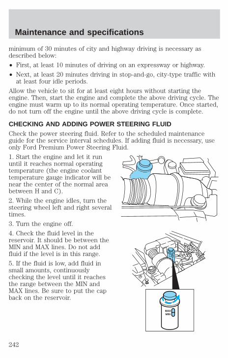
minimum of 30 minutes of city and highway driving is necessary asdescribed below:
• First, at least 10 minutes of driving on an expressway or highway.
• Next, at least 20 minutes driving in stop-and-go, city-type traffic withat least four idle periods.
Allow the vehicle to sit for at least eight hours without starting theengine. Then, start the engine and complete the above driving cycle. Theengine must warm up to its normal operating temperature. Once started,do not turn off the engine until the above driving cycle is complete.
CHECKING AND ADDING POWER STEERING FLUIDCheck the power steering fluid. Refer to the scheduled maintenanceguide for the service interval schedules. If adding fluid is necessary, useonly Ford Premium Power Steering Fluid.
1. Start the engine and let it rununtil it reaches normal operatingtemperature (the engine coolanttemperature gauge indicator will benear the center of the normal areabetween H and C).
2. While the engine idles, turn thesteering wheel left and right severaltimes.
3. Turn the engine off.
4. Check the fluid level in thereservoir. It should be between theMIN and MAX lines. Do not addfluid if the level is in this range.
5. If the fluid is low, add fluid insmall amounts, continuouslychecking the level until it reachesthe range between the MIN andMAX lines. Be sure to put the capback on the reservoir.
MAXMIN
MAXMIN
Maintenance and specifications
242
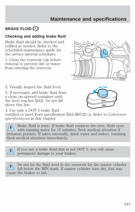
BRAKE FLUID
Checking and adding brake fluidBrake fluid should be checked andrefilled as needed. Refer to thescheduled maintenance guide forthe service interval schedules.
1. Clean the reservoir cap beforeremoval to prevent dirt or waterfrom entering the reservoir.
2. Visually inspect the fluid level.
3. If necessary, add brake fluid froma clean un-opened container untilthe level reaches MAX. Do not fillabove this line.
4. Use only a DOT 3 brake fluidcertified to meet Ford specification ESA-M6C25–A. Refer to Lubricantspecifications in this chapter.
Brake fluid is toxic. If brake fluid contacts the eyes, flush eyeswith running water for 15 minutes. Seek medical attention if
irritation persists. If taken internally, drink water and induce vomiting.Seek medical attention immediately.
If you use a brake fluid that is not DOT 3, you will causepermanent damage to your brakes.
Do not let the fluid level in the reservoir for the master cylinderfall below the MIN mark. If master cylinder runs dry, this may
cause the brakes to fail.
MAX
MIN
Maintenance and specifications
243
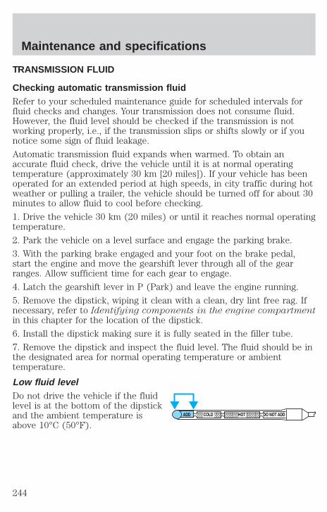
TRANSMISSION FLUID
Checking automatic transmission fluidRefer to your scheduled maintenance guide for scheduled intervals forfluid checks and changes. Your transmission does not consume fluid.However, the fluid level should be checked if the transmission is notworking properly, i.e., if the transmission slips or shifts slowly or if younotice some sign of fluid leakage.
Automatic transmission fluid expands when warmed. To obtain anaccurate fluid check, drive the vehicle until it is at normal operatingtemperature (approximately 30 km [20 miles]). If your vehicle has beenoperated for an extended period at high speeds, in city traffic during hotweather or pulling a trailer, the vehicle should be turned off for about 30minutes to allow fluid to cool before checking.
1. Drive the vehicle 30 km (20 miles) or until it reaches normal operatingtemperature.
2. Park the vehicle on a level surface and engage the parking brake.
3. With the parking brake engaged and your foot on the brake pedal,start the engine and move the gearshift lever through all of the gearranges. Allow sufficient time for each gear to engage.
4. Latch the gearshift lever in P (Park) and leave the engine running.
5. Remove the dipstick, wiping it clean with a clean, dry lint free rag. Ifnecessary, refer to Identifying components in the engine compartmentin this chapter for the location of the dipstick.
6. Install the dipstick making sure it is fully seated in the filler tube.
7. Remove the dipstick and inspect the fluid level. The fluid should be inthe designated area for normal operating temperature or ambienttemperature.
Low fluid levelDo not drive the vehicle if the fluidlevel is at the bottom of the dipstickand the ambient temperature isabove 10°C (50°F).
ADD COLD HOT DO NOT ADD
Maintenance and specifications
244

Correct fluid levelThe transmission fluid should be checked at normal operatingtemperature 66°C-77°C (150°F-170°F) on a level surface. The normaloperating temperature can be reached after approximately 30 km (20miles) of driving.
You can check the fluid without driving if the ambient temperature isabove 10°C (50°F). However, if fluid is added at this time, an overfillcondition could result when the vehicle reaches normal operatingtemperature.
The transmission fluid should be inthis range if at normal operatingtemperature (66°C-77°C[150°F-170°F]).
The transmission fluid should be inthis range if at ambient temperature(10°C-35°C [50°F-95°F]).
High fluid levelFluid levels above the safe rangemay result in transmission failure.An overfill condition of transmissionfluid may cause shift and/orengagement concerns and/or possible damage.
High fluid levels can be caused by an overheating condition.
Adjusting automatic transmission fluid levelsBefore adding any fluid, make sure the correct type is used. The type offluid used is normally indicated on the dipstick and also in theLubricant specifications section in this chapter.
Use of a non-approved automatic transmission fluid may causeinternal transmission component damage.
If necessary, add fluid in 250 mL (1/2 pint) increments through the fillertube until the level is correct.
ADD COLD HOT DO NOT ADD
ADD COLD HOT DO NOT ADD
ADD COLD HOT DO NOT ADD
Maintenance and specifications
245
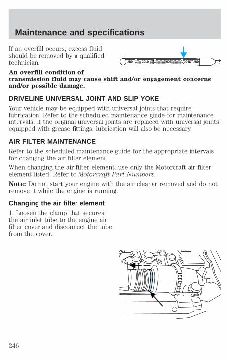
If an overfill occurs, excess fluidshould be removed by a qualifiedtechnician.
An overfill condition oftransmission fluid may cause shift and/or engagement concernsand/or possible damage.
DRIVELINE UNIVERSAL JOINT AND SLIP YOKEYour vehicle may be equipped with universal joints that requirelubrication. Refer to the scheduled maintenance guide for maintenanceintervals. If the original universal joints are replaced with universal jointsequipped with grease fittings, lubrication will also be necessary.
AIR FILTER MAINTENANCERefer to the scheduled maintenance guide for the appropriate intervalsfor changing the air filter element.
When changing the air filter element, use only the Motorcraft air filterelement listed. Refer to Motorcraft Part Numbers.
Note: Do not start your engine with the air cleaner removed and do notremove it while the engine is running.
Changing the air filter element1. Loosen the clamp that securesthe air inlet tube to the engine airfilter cover and disconnect the tubefrom the cover.
ADD COLD HOT DO NOT ADD
Maintenance and specifications
246

2. Loosen the clamp that securesthe air filter cover to the air filterhousing and carefully separate thecover from housing.
3. Remove the air filter elementfrom the air filter housing.
4. Install a new air filter element. Be careful not to crimp the filterelement edges between the air filter housing and cover. This could causefilter damage and allow unmetered air to enter the engine if not properlyseated.
5. Replace the air filter cover and secure the clamp.
6. Replace the air inlet tube and secure the clamp.
Maintenance and specifications
247

INFORMATION ABOUT UNIFORM TIRE QUALITY GRADINGNew vehicles are fitted with tiresthat have a rating on them calledTire Quality Grades. The Qualitygrades can be found whereapplicable on the tire sidewallbetween tread shoulder andmaximum section width. Forexample:
• Treadwear 200 Traction AA Temperature A
These Tire Quality Grades are determined by standards that the UnitedStates Department of Transportation has set.
Tire Quality Grades apply to new pneumatic tires for use on passengercars. They do not apply to deep tread, winter-type snow tires,space-saver or temporary use spare tires, tires with nominal rimdiameters of 10 to 12 inches or limited production tires as defined inTitle 49 Code of Federal Regulations Part 575.104(c)(2).
U.S. Department of Transportation-Tire quality grades: The U.S.Department of Transportation requires Ford to give you the followinginformation about tire grades exactly as the government has written it.
TreadwearThe treadwear grade is a comparative rating based on the wear rate ofthe tire when tested under controlled conditions on a specifiedgovernment test course. For example, a tire graded 150 would wear oneand one-half (1 1/2) times as well on the government course as a tiregraded 100. The relative performance of tires depends upon the actualconditions of their use, however, and may depart significantly from thenorm due to variations in driving habits, service practices, anddifferences in road characteristics and climate.
Traction AA A B CThe traction grades, from highest to lowest are AA, A, B, and C. Thegrades represent the tire’s ability to stop on wet pavement as measuredunder controlled conditions on specified government test surfaces ofasphalt and concrete. A tire marked C may have poor tractionperformance.
Maintenance and specifications
248
The traction grade assigned to this tire is based onstraight-ahead braking traction tests, and does not include
acceleration, cornering, hydroplaning or peak traction characteristics.
Temperature A B CThe temperature grades are A (the highest), B, and C, representing thetire’s resistance to the generation of heat and its ability to dissipate heatwhen tested under controlled conditions on a specified indoor laboratorytest wheel. Sustained high temperature can cause the material of the tireto degenerate and reduce tire life, and excessive temperature can lead tosudden tire failure. The grade C corresponds to a level of performancewhich all passenger car tires must meet under the Federal Motor VehicleSafety Standard No. 109. Grades B and A represent higher levels ofperformance on the laboratory test wheel than the minimum required bylaw.
The temperature grade for this tire is established for a tire thatis properly inflated and not overloaded. Excessive speed,
underinflation, or excessive loading, either separately or incombination, can cause heat buildup and possible tire failure.
SERVICING YOUR TIRES
Checking the tire pressure• Use an accurate tire pressure gauge.
• Check the tire pressure when tires are cold, after the vehicle has beenparked for at least one hour or has been driven less than 5 km (3miles).
• Adjust tire pressure to recommended specifications found on theCertification Label. Tire pressure information can also be found on theTire Information label located on the inside of the fuel filler door.
Improperly inflated tires can affect vehicle handling and can failsuddenly, possibly resulting in loss of vehicle control.
Maintenance and specifications
249

Tire rotationBecause your vehicle’s tires perform different jobs, they often weardifferently. To make sure your tires wear evenly and last longer, rotatethem as indicated in the scheduled maintenance guide. If you notice thatthe tires wear unevenly, have them checked.
• Four tire rotation
Replacing the tiresReplace the tires when the wearband is visible through the tiretreads.
When replacing full size tires, never mix radial bias-belted, orbias-type tires. Use only the tire sizes that are listed on the
Certification Label. Make sure that all tires are the same size, speedrating, and load-carrying capacity. Use only the tire combinationsrecommended on the label. If you do not follow these precautions,your vehicle may not drive properly and safely.
Make sure that all replacement tires are of the same size, type,load-carrying capacity and tread design (e.g., “All Terrain”, etc.),
as originally offered by Ford.
Maintenance and specifications
250
Do not replace your tires with “high performance” tires or largersize tires.
Failure to follow these precautions may adversely affect thehandling of the vehicle and make it easier for the driver to lose
control and roll over.
Tires that are larger or smaller than your vehicle’s original tires may alsoaffect the accuracy of your speedometer.
SNOW TIRES AND CHAINS
Snow tires must be the same size and grade as the tires youcurrently have on your vehicle.
The tires on your vehicle have all weather treads to provide traction inrain and snow. However, in some climates, you may need to use snowtires and chains.
Follow these guidelines when using snow tires and chains:
• Use only cable type chains offered by Ford as an accessory orequivalent. SAE class “S” or other conventional link type chains maycontact and cause damage to the vehicle’s wheel house and/or body.
• Install chains securely, verifying that the chains do not touch anywiring, brake lines or fuel lines.
• Drive cautiously. If you hear the chains rub or bang against yourvehicle, stop and re-tighten the chains. If this does not work, removethe chains to prevent damage to your vehicle.
• If possible, avoid fully loading your vehicle.
• Remove the tire chains when they are no longer needed. Do not usetire chains on dry roads.
• The suspension insulation and bumpers will help prevent vehicledamage. Do not remove these components from your vehicle whenusing snow tires and chains.
• Do not exceed 48 km/h (30 mph) with tire chains on your vehicle.
Maintenance and specifications
251

MOTORCRAFT PART NUMBERS
Component 5.4L 4V V8 engine
Air filter element FA-1634Battery (standard) BXT-65-650Fuel filter FG-986BOil filter FL-820-SPCV valve EV-233Spark plugs* AWSF-32P
* Refer to Vehicle Emissions Control Information (VECI) decal for sparkplug gap information.
Maintenance and specifications
252
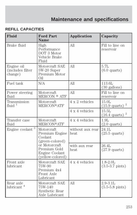
REFILL CAPACITIES
Fluid Ford PartName
Application Capacity
Brake fluid HighPerformanceDOT 3 MotorVehicle BrakeFluid
All Fill to line onreservoir
Engine oil(includes filterchange)
Motorcraft SAE5W-20 SuperPremium MotorOil
All 5.7L(6.0 quarts)
Fuel tank N/A All 113.6L(30 gallons)
Power steeringfluid
MotorcraftMERCON t ATF
All Fill to line onreservoir
Transmissionfluid 1
MotorcraftMERCONtATF
4 x 2 vehicles 15.0L(15.9 quarts) 2
4 x 4 vehicles 15.5L(16.4 quarts) 2
Transfer casefluid
MotorcraftMERCONtATF
4 x 4 vehicles 1.9L(2.0 quarts)
Engine coolant 3 MotorcraftPremium EngineCoolant(green-colored)or MotorcraftPremium GoldEngine Coolant(yellow-colored)
without aux rearheat
24.1L(25.5 quarts)
with aux rearheat
26.4L(27.9 quarts)
Front axlelubricant
Motorcraft SAE75W-90Premium 4x4Front AxleLubricant
4 x 4 vehicles 1.8-2.0L(3.5-3.7 pints)
Rear axlelubricant 4
Motorcraft SAE75W-140Synthetic RearAxle Lubricant
All 2.9-3.1L(5.5-5.8 pints)
Maintenance and specifications
253

Fluid Ford PartName
Application Capacity
Windshieldwasher fluid
Ultra-ClearWindshieldWasherConcentrate
All 4.1L(4.5 quarts)
1Ensure the correct automatic transmission fluid is used. Transmissionfluid requirements are indicated on the dipstick or on the dipstickhandle. Check the container to verify the fluid being added is of thecorrect type. Refer to your scheduled maintenance guide to determinethe correct service interval.
Some transmission fluids may be labeled as dual usage, such asMERCONt and MERCONt V. These dual usage fluids are not to be usedin an automatic transmission that requires use of the MERCONt typefluid. However, these dual usage fluids may be used in transmissions thatrequire the MERCONt V type fluid.
MERCONt and MERCONt V type fluids are not interchangeable.DO NOT mix MERCONt and MERCONt V. Use of a transmissionfluid that indicates dual usage (MERCONt and MERCONt V) inan automatic transmission application requiring MERCONt maycause transmission damage. Use of any fluid other than therecommended fluid may cause transmission damage.2Indicates only approximate dry-fill capacity. Some applications may varybased on cooler size and if equipped with an in-tank cooler. The amountof transmission fluid and fluid level should be set by the indication onthe dipstick’s normal operating range.3Add the coolant type originally equipped in your vehicle.4Your vehicle’s rear axle is filled with a synthetic rear axle lubricant andis considered lubricated for life. These lubricants are not to be checkedor changed unless a leak is suspected, service is required or the axle hasbeen submerged in water. The axle lubricant should be changed any timethe axle has been submerged in water. Add 118 ml (4 oz.) of AdditiveFriction Modifier C8AZ-19B546–A or equivalent meeting Fordspecification EST-M2C118–A for complete refill of Traction-Lok axles.
Service refill capacities are determined by filling the rear axle 6 mm to14 mm (1/4 inch to 9/16 inch) below the bottom of the filler hole.
Maintenance and specifications
254
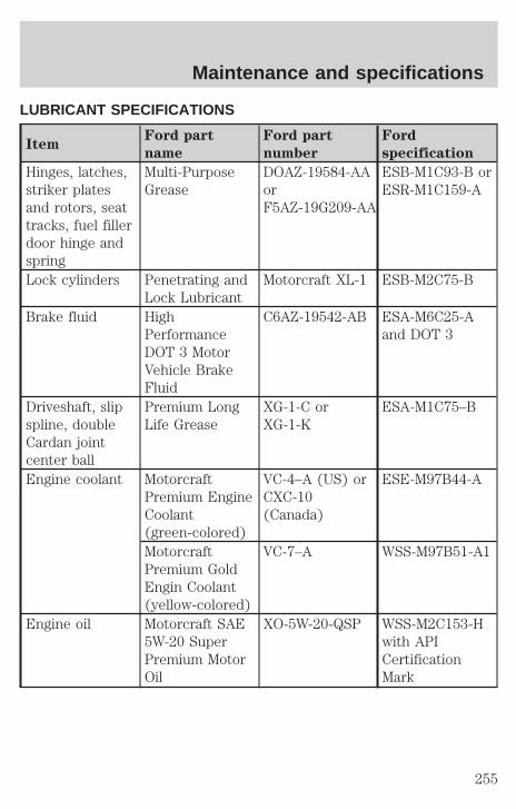
LUBRICANT SPECIFICATIONS
ItemFord part
name
Ford part
number
Ford
specification
Hinges, latches,striker platesand rotors, seattracks, fuel fillerdoor hinge andspring
Multi-PurposeGrease
DOAZ-19584-AAorF5AZ-19G209-AA
ESB-M1C93-B orESR-M1C159-A
Lock cylinders Penetrating andLock Lubricant
Motorcraft XL-1 ESB-M2C75-B
Brake fluid HighPerformanceDOT 3 MotorVehicle BrakeFluid
C6AZ-19542-AB ESA-M6C25-Aand DOT 3
Driveshaft, slipspline, doubleCardan jointcenter ball
Premium LongLife Grease
XG-1-C orXG-1-K
ESA-M1C75–B
Engine coolant MotorcraftPremium EngineCoolant(green-colored)
VC-4–A (US) orCXC-10(Canada)
ESE-M97B44-A
MotorcraftPremium GoldEngin Coolant(yellow-colored)
VC-7–A WSS-M97B51-A1
Engine oil Motorcraft SAE5W-20 SuperPremium MotorOil
XO-5W-20-QSP WSS-M2C153-Hwith APICertificationMark
Maintenance and specifications
255
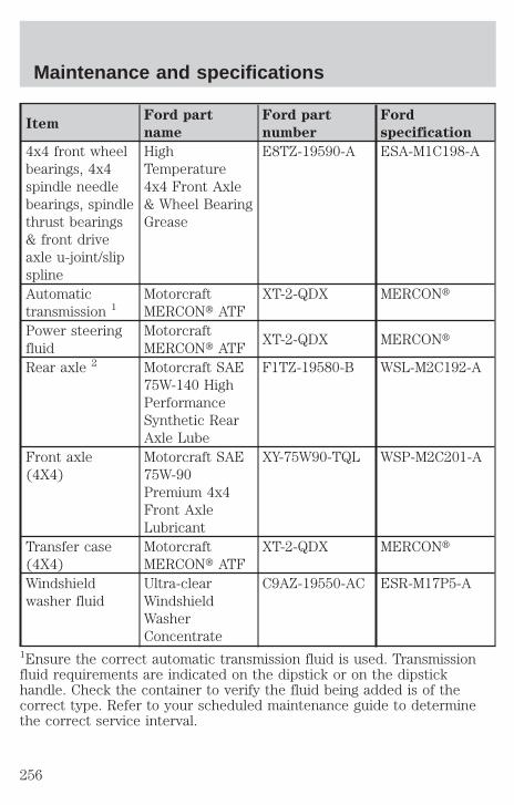
ItemFord part
name
Ford part
number
Ford
specification
4x4 front wheelbearings, 4x4spindle needlebearings, spindlethrust bearings& front driveaxle u-joint/slipspline
HighTemperature4x4 Front Axle& Wheel BearingGrease
E8TZ-19590-A ESA-M1C198-A
Automatictransmission 1
MotorcraftMERCONt ATF
XT-2-QDX MERCONt
Power steeringfluid
MotorcraftMERCONt ATF
XT-2-QDX MERCONt
Rear axle 2 Motorcraft SAE75W-140 HighPerformanceSynthetic RearAxle Lube
F1TZ-19580-B WSL-M2C192-A
Front axle(4X4)
Motorcraft SAE75W-90Premium 4x4Front AxleLubricant
XY-75W90-TQL WSP-M2C201-A
Transfer case(4X4)
MotorcraftMERCONt ATF
XT-2-QDX MERCONt
Windshieldwasher fluid
Ultra-clearWindshieldWasherConcentrate
C9AZ-19550-AC ESR-M17P5-A
1Ensure the correct automatic transmission fluid is used. Transmissionfluid requirements are indicated on the dipstick or on the dipstickhandle. Check the container to verify the fluid being added is of thecorrect type. Refer to your scheduled maintenance guide to determinethe correct service interval.
Maintenance and specifications
256
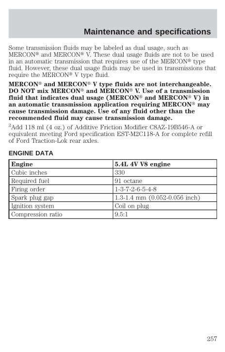
Some transmission fluids may be labeled as dual usage, such asMERCONt and MERCONt V. These dual usage fluids are not to be usedin an automatic transmission that requires use of the MERCONt typefluid. However, these dual usage fluids may be used in transmissions thatrequire the MERCONt V type fluid.
MERCONt and MERCONt V type fluids are not interchangeable.DO NOT mix MERCONt and MERCONt V. Use of a transmissionfluid that indicates dual usage (MERCONt and MERCONt V) inan automatic transmission application requiring MERCONt maycause transmission damage. Use of any fluid other than therecommended fluid may cause transmission damage.2Add 118 ml (4 oz.) of Additive Friction Modifier C8AZ-19B546-A orequivalent meeting Ford specification EST-M2C118-A for complete refillof Ford Traction-Lok rear axles.
ENGINE DATA
Engine 5.4L 4V V8 engine
Cubic inches 330Required fuel 91 octaneFiring order 1-3-7-2-6-5-4-8Spark plug gap 1.3-1.4 mm (0.052-0.056 inch)Ignition system Coil on plugCompression ratio 9.5:1
Maintenance and specifications
257
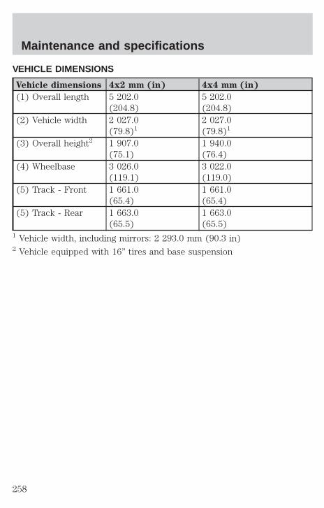
VEHICLE DIMENSIONS
Vehicle dimensions 4x2 mm (in) 4x4 mm (in)
(1) Overall length 5 202.0(204.8)
5 202.0(204.8)
(2) Vehicle width 2 027.0(79.8)1
2 027.0(79.8)1
(3) Overall height2 1 907.0(75.1)
1 940.0(76.4)
(4) Wheelbase 3 026.0(119.1)
3 022.0(119.0)
(5) Track - Front 1 661.0(65.4)
1 661.0(65.4)
(5) Track - Rear 1 663.0(65.5)
1 663.0(65.5)
1 Vehicle width, including mirrors: 2 293.0 mm (90.3 in)2 Vehicle equipped with 16” tires and base suspension
Maintenance and specifications
258

4
1
3
5
2
Maintenance and specifications
259

IDENTIFYING YOUR VEHICLE
Certification labelThe National Highway Traffic SafetyAdministration Regulations requirethat a Certification label be affixedto a vehicle and prescribe where theCertification label may be located.The Certification label is located onthe front door latch pillar on thedriver’s side.
Vehicle identification numberThe vehicle identification number isattached to a metal tag and islocated on the driver sideinstrument panel. (Please note thatin the graphic XXXX isrepresentative of your vehicleidentification number.)
Engine numberThe engine number (the last eight numbers of the vehicle identificationnumber) is stamped on the engine block and transmission.
XXXXXXXXXXXXXXXXX
Maintenance and specifications
260
FORD ACCESSORIES FOR YOUR VEHICLEA wide selection of genuine Ford accessories are available for yourvehicle through your local authorized Ford, Lincoln, Mercury or Ford ofCanada dealer. These quality accessories have been specificallyengineered to fulfill your automotive needs; they are custom designed tocomplement the style and aerodynamic appearance of your vehicle. Inaddition, each accessory is made from high quality materials and meetsor exceeds Ford’s rigorous engineering and safety specifications. FordMotor Company will repair or replace any properly dealer-installed Fordaccessory found to be defective in factory-supplied materials orworkmanship during the warranty period, as well as any componentdamaged by the defective accessory. The accessory will be warranted forwhichever provides you the greatest benefit:
• 12 months or 20 000 km (12 000 miles) (whichever occurs first), or
• The remainder of your new vehicle limited warranty.
This means that genuine Ford accessories purchased along with yournew vehicle and installed by the dealer are covered for the full length ofyour New Vehicle’s Limited Warranty — 3 years or 60 000 km (36 000miles) (whichever occurs first). Contact your dealer for details and acopy of the warranty.
Not all accessories are available for all models.
Vehicle SecurityStyled wheel protector locks
Vehicle security systems
Comfort and convenienceBattery warmer
Cabin air filter
Cargo nets
Cargo organizer
Cargo storage box
Cargo tray
Engine block heater
Tire step
Accessories
261
Travel equipmentDaytime running lights (DRL)
Heavy-duty battery
Raised cross bars
Raised cross bar adaptors
Rear mount bike rack
Seatback organizer
Soft luggage carrier
Towing mirrors (removable and permanent)
Trailer hitch bars and balls
Trailer hitch mounted bike carrier
Trailer hitch wiring adaptor
Protection and appearance equipmentAir bag anti-theft locks
Bike carrier
Cargo liners, interior
Carpet floor mats
Door edge guards
Flat splash guards
Front end covers (full)
Hood deflector
Instrument panel trim (woodgrain)
Kayak/canoe carrier
Load warrior carrier basket
Locking gas cap
Luggage basket
Molded splash guards
Molded vinyl floor mats
Moonroof deflector
Rear air deflectors
Accessories
262
Side window air deflectors
Ski/snowboard adaptor
Snow traction cables
Truck cover
Underbody security lighting
Universal floor mats
Wheels
For maximum vehicle performance, keep the following information inmind when adding accessories or equipment to your vehicle:
• When adding accessories, equipment, passengers and luggage to yourvehicle, do not exceed the total weight capacity of the vehicle or ofthe front or rear axle (GVWR or GAWR as indicated on the Safetycompliance certification label). Consult your dealer for specific weightinformation.
• The Federal Communications Commission (FCC) and Canadian RadioTelecommunications Commission (CRTC) regulate the use of mobilecommunications systems - such as two-way radios, telephones andtheft alarms - that are equipped with radio transmitters. Any suchequipment installed in your vehicle should comply with FCC or CRTCregulations and should be installed only by a qualified servicetechnician.
• Mobile communications systems may harm the operation of yourvehicle, particularly if they are not properly designed for automotiveuse or are not properly installed. When operated, such systems maycause the engine to stumble or stall or cause the transmission to bedamaged or operate improperly. In addition, such systems may bedamaged or their performance may be affected by operating yourvehicle. (Citizens band [CB] transceivers, garage door openers andother transmitters with outputs of five watts or less will not ordinarilyaffect your vehicle’s operation.)
• Ford cannot assume responsibility for any adverse effects or damagethat may result from the use of such equipment.
Accessories
263
A
Accessory delay ..........................67
Air bag supplementalrestraint system ........124–125, 129
and child safety seats ............127description ......................125, 129disposal ....................................132driver air bag ..................127, 130indicator light ...........12, 129, 131operation .........................127, 130passenger air bag ...........127, 130side air bag ..............................129
Air cleaner filter ...............246, 252
Air conditioning ..........................37auxiliary heater and airconditioner ................................43rear seat controls .....................42
Air suspension ...........................150description ..............................150warning light .............................12
Ambulance packages ....................7
Antifreeze(see Engine coolant) ................225
Anti-lock brake system(see Brakes) ..............................147
Anti-theft systemwarning light .............................13
Automatic transmissiondriving an automaticoverdrive .................................154fluid, adding ............................244fluid, checking ........................244fluid, refill capacities ..............253fluid, specification ..................257
Auxiliary power point .................65
Axlelubricant specifications ..255, 257refill capacities ........................253traction lok ..............................152
B
Battery .......................................223acid, treating emergencies .....223charging systemwarning light .............................12jumping a disabled battery ....194maintenance-free ....................223replacement, specifications ...252servicing ..................................223voltage gauge ............................16
Belt minder ...............................120
Brakes ........................................146anti-lock ...................................147anti-lock brake system(ABS) warning light .........11, 148brake warning light ..................11fluid, checking and adding ....243fluid, refill capacities ..............253fluid, specifications .........255, 257lubricant specifications ..255, 257parking ....................................148pedals (see Poweradjustable foot pedals) ............70shift interlock ..........................153
Break-in period .............................5
C
Capacities for refilling fluids ....253
Cassette tape player ...................18
CD changer .................................32
Cellular telephone (see yourCellular Phone Guide) ................82
Index
264
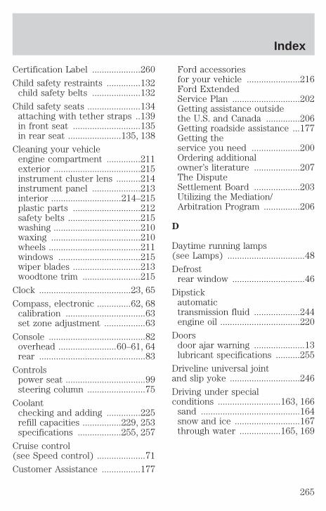
Certification Label ....................260
Child safety restraints ..............132child safety belts ....................132
Child safety seats ......................134attaching with tether straps ..139in front seat ............................135in rear seat ......................135, 138
Cleaning your vehicleengine compartment ..............211exterior ....................................215instrument cluster lens ..........214instrument panel ....................213interior .............................214–215plastic parts ............................212safety belts ..............................215washing ....................................210waxing .....................................210wheels ......................................211windows ..................................215wiper blades ............................213woodtone trim ........................215
Clock ......................................23, 65
Compass, electronic ..............62, 68calibration .................................63set zone adjustment .................63
Console ........................................82overhead ........................60–61, 64rear ............................................83
Controlspower seat .................................99steering column ........................75
Coolantchecking and adding ..............225refill capacities ................229, 253specifications ..................255, 257
Cruise control(see Speed control) ....................71
Customer Assistance ................177
Ford accessoriesfor your vehicle ......................216Ford ExtendedService Plan ............................202Getting assistance outsidethe U.S. and Canada ..............206Getting roadside assistance ...177Getting theservice you need ....................200Ordering additionalowner’s literature ...................207The DisputeSettlement Board ...................203Utilizing the Mediation/Arbitration Program ...............206
D
Daytime running lamps(see Lamps) ................................48
Defrostrear window ..............................46
Dipstickautomatictransmission fluid ...................244engine oil .................................220
Doorsdoor ajar warning .....................13lubricant specifications ..........255
Driveline universal jointand slip yoke .............................246
Driving under specialconditions ..........................163, 166
sand .........................................164snow and ice ...........................167through water .................165, 169
Index
265
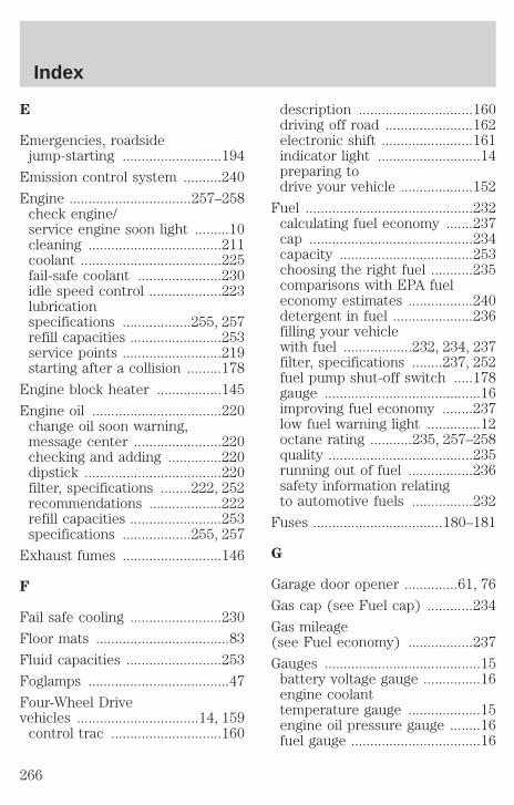
E
Emergencies, roadsidejump-starting ..........................194
Emission control system ..........240
Engine ................................257–258check engine/service engine soon light .........10cleaning ...................................211coolant .....................................225fail-safe coolant ......................230idle speed control ...................223lubricationspecifications ..................255, 257refill capacities ........................253service points ..........................219starting after a collision .........178
Engine block heater .................145
Engine oil ..................................220change oil soon warning,message center .......................220checking and adding ..............220dipstick ....................................220filter, specifications ........222, 252recommendations ...................222refill capacities ........................253specifications ..................255, 257
Exhaust fumes ..........................146
F
Fail safe cooling ........................230
Floor mats ...................................83
Fluid capacities .........................253
Foglamps .....................................47
Four-Wheel Drivevehicles ................................14, 159
control trac .............................160
description ..............................160driving off road .......................162electronic shift ........................161indicator light ...........................14preparing todrive your vehicle ...................152
Fuel ............................................232calculating fuel economy .......237cap ...........................................234capacity ...................................253choosing the right fuel ...........235comparisons with EPA fueleconomy estimates .................240detergent in fuel .....................236filling your vehiclewith fuel ..................232, 234, 237filter, specifications ........237, 252fuel pump shut-off switch .....178gauge .........................................16improving fuel economy ........237low fuel warning light ..............12octane rating ...........235, 257–258quality ......................................235running out of fuel .................236safety information relatingto automotive fuels ................232
Fuses ..................................180–181
G
Garage door opener ..............61, 76
Gas cap (see Fuel cap) ............234
Gas mileage(see Fuel economy) .................237
Gauges .........................................15battery voltage gauge ...............16engine coolanttemperature gauge ...................15engine oil pressure gauge ........16fuel gauge ..................................16
Index
266

odometer ...................................17speedometer .............................17tachometer ................................17trip odometer ............................17
GAWR(Gross Axle Weight Rating) .....170
calculating ...............................172definition .................................170driving with a heavy load ......170location ....................................170
GVWR (GrossVehicle Weight Rating) .............170
calculating .......................170, 172definition .................................170driving with a heavy load ......170location ....................................170
H
Hazard flashers .........................178
Head restraints ...................99, 104
Headlamps ...................................47aiming ..................................49–50autolamp system .......................47bulb specifications ....................52daytime running lights .............48flash to pass ..............................48high beam ...........................13, 48replacing bulbs .........................53turning on and off ....................47warning chime ..........................14
Heating ........................................37
HomeLink universaltransceiver (seeGarage door opener) ............76–79
Hood ..........................................218
I
Ignition .......................142, 257–258
Infant seats(see Safety seats) .....................134
Inspection/maintenance (I/M) testing .......241
Instrument panelcleaning ...................................213cluster ................................10, 214lighting uppanel and interior .....................48
J
Jack ............................................188positioning ...............................188storage .....................................188
Jump-starting your vehicle ......194
K
Keyless entry systemautolock .....................................92locking and unlocking doors ....94programming entry code .........93
Keys .......................................95–97key in ignition chime ...............14positions of the ignition .........142
L
Lampsautolamp system .......................47bulb replacementspecifications chart ..................52cargo lamps ...............................48daytime running light ...............48fog lamps ...................................47headlamps .................................47
Index
267
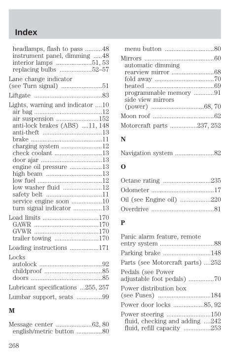
headlamps, flash to pass ..........48instrument panel, dimming .....48interior lamps .....................51, 53replacing bulbs ...................52–57
Lane change indicator(see Turn signal) ........................51
Liftgate ........................................83
Lights, warning and indicator ....10air bag ........................................12air suspension .........................152anti-lock brakes (ABS) ....11, 148anti-theft ...................................13brake ..........................................11charging system ........................12check coolant ............................13door ajar ....................................13engine oil pressure ...................13high beam .................................13low fuel ......................................12low washer fluid .......................12safety belt .................................11service engine soon ..................10turn signal indicator .................13
Load limits .................................170GAWR ......................................170GVWR ......................................170trailer towing ..........................170
Loading instructions .................171
Locksautolock .....................................92childproof ..................................85doors ..........................................85
Lubricant specifications ...255, 257
Lumbar support, seats ...............99
M
Message center .....................62, 80english/metric button ...............80
menu button .............................80
Mirrors .........................................60automatic dimmingrearview mirror .........................68fold away ...................................70heated ........................................69programmable memory ............91side view mirrors(power) ...............................68, 70
Moon roof ....................................62
Motorcraft parts ................237, 252
N
Navigation system .......................82
O
Octane rating ............................235
Odometer .....................................17
Oil (see Engine oil) ..................220
Overdrive .....................................81
P
Panic alarm feature, remoteentry system ................................88
Parking brake ............................148
Parts (see Motorcraft parts) ....252
Pedals (see Poweradjustable foot pedals) ...............70
Power distribution box(see Fuses) ...............................184
Power door locks ..................85, 92
Power steering ..........................150fluid, checking and adding ....242fluid, refill capacity ................253
Index
268
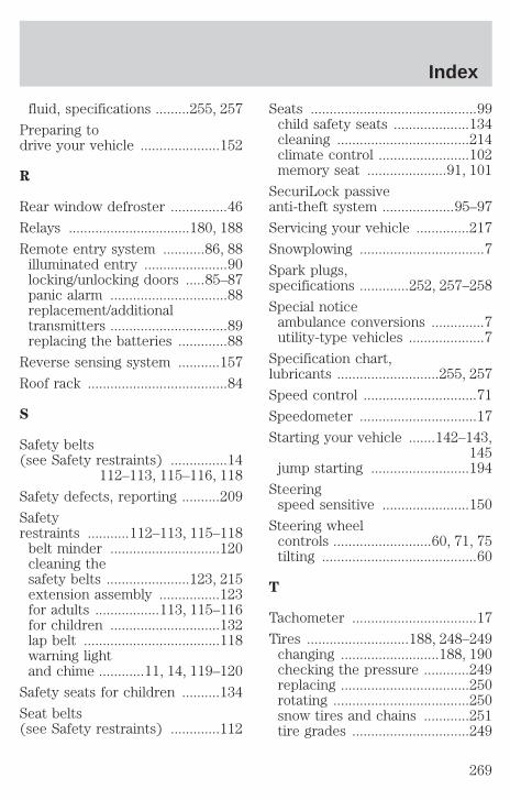
fluid, specifications .........255, 257
Preparing todrive your vehicle .....................152
R
Rear window defroster ...............46
Relays ................................180, 188
Remote entry system ...........86, 88illuminated entry ......................90locking/unlocking doors .....85–87panic alarm ...............................88replacement/additionaltransmitters ...............................89replacing the batteries .............88
Reverse sensing system ...........157
Roof rack .....................................84
S
Safety belts(see Safety restraints) ...............14
112–113, 115–116, 118
Safety defects, reporting ..........209
Safetyrestraints ...........112–113, 115–118
belt minder .............................120cleaning thesafety belts ......................123, 215extension assembly ................123for adults .................113, 115–116for children .............................132lap belt ....................................118warning lightand chime ............11, 14, 119–120
Safety seats for children ..........134
Seat belts(see Safety restraints) .............112
Seats ............................................99child safety seats ....................134cleaning ...................................214climate control ........................102memory seat .....................91, 101
SecuriLock passiveanti-theft system ...................95–97
Servicing your vehicle ..............217
Snowplowing .................................7
Spark plugs,specifications .............252, 257–258
Special noticeambulance conversions ..............7utility-type vehicles ....................7
Specification chart,lubricants ...........................255, 257
Speed control ..............................71
Speedometer ...............................17
Starting your vehicle .......142–143,145
jump starting ..........................194
Steeringspeed sensitive .......................150
Steering wheelcontrols ..........................60, 71, 75tilting .........................................60
T
Tachometer .................................17
Tires ...........................188, 248–249changing ..........................188, 190checking the pressure ............249replacing ..................................250rotating ....................................250snow tires and chains ............251tire grades ...............................249
Index
269

treadwear ................................248
Towing .......................................172recreational towing .................176trailer towing ..........................172wrecker ....................................199
Traction-lok rear axle ...............152
Transmission .............................153fluid, checking and adding(automatic) .............................244fluid, refill capacities ..............253lubricant specifications ..255, 257
Trip odometer .............................17
Turn signal ............................13, 51
V
Vehicle dimensions ...................258
Vehicle Identification Number(VIN) ..........................................260
Vehicle loading ..........................170
Ventilating your vehicle ...........146
W
Warning chimes ...........................14
Warning lights (see Lights) .......10
Washer fluid ..............................220
Water, Driving through .............169
Windowspower .........................................66rear wiper/washer .....................58
Windshield washer fluid andwipers
checking and adding fluid .....220checking and cleaning ..............59liftgate reservoir .....................220operation ...................................58replacing wiper blades .............59
Wrecker towing .........................199
Index
270

271

272