Embed Size (px)
Citation preview

02-385 Chapter 890 page 1
Draft 5/18/17
02 DEPARTMENT OF PROFESSIONAL AND FINANCIAL REGULATION 385 MANUFACTURED HOUSING BOARD Chapter 890: MANUFACTURED HOME INSTALLATION STANDARDS SUMMARY: These rules are drafted pursuant to 10 M.R.S. §9061, 42 U.S.C. §5404(c)(2)(section 605(c)(2) to implement the National Manufactured Housing Construction and Safety Standards Act of 1974. This chapter sets forth minimum requirements for the initial installation of new manufactured homes in accordance with federal standards. SUBCHAPTER A -– GENERAL I. Administration
A. Scope
These Installation Standards provide minimum requirements for the initial installation of new manufactured homes, in accordance with Section 605 of the Act (42 U.S.C. §5404). The Installation Standards are one component of the Manufactured Home Installation Program in Part 3286, and upon effect, serve as the basis for developing the manufacturers’ installation instructions as required by Section II of this subchapter. The manufacturers’ installation instructions, including specific methods for performing a specific operation or assembly, will be deemed to comply with these Installation Standards, provided they meet or exceed the minimum requirements of these Installation Standards and do not take the home out of compliance with the Manufactured Home Construction and Safety Standards (MHCSS) (24 CFR part 3280). Work necessary to join all sections of a multi-section home specifically identified in sSubchapters G, H, and I, or work associated with connecting exterior lights, chain-hung light fixtures, or ceiling-suspended fans, as specifically identified in Subchapter IH, is not considered assembly or construction of the home, although design of those elements of a manufactured home must comply with the Manufactured Home Construction and Safety Standards (MHCSS). However, work associated with the completion of hinged roofs and eaves in Subchapter I, Section I and other work done on-site and not specifically identified in this part as close-up is considered construction and assembly and is subject to the requirements of the Manufactured Home Construction and Safety Standards MHCSS (24 CFR part 3280) and the Manufactured Home Procedural and Enforcement Regulation (MHPER) (24 CFR part 3282). This standard covers the installation of manufactured homes, wherever located.
B. Intended Usage of Manufactured Homes Covered Under thisese Standards
The provisions of thisese standards are intended to apply to manufactured homes (single section, multiple section or expanded types) for use as a single family dwelling. The following homes are included: Those units constructed after June 15, 1976, which the manufacturer certifies are constructed in compliance with the HUD standard, meaning structures, transportable in

02-385 Chapter 890 page 2
Draft 5/18/17
one or more sections, which in the traveling mode, are 8 body feet or more in width and 40 body feet or more in length or, when erected on site, are 320 or more square feet, and which are built on a permanent chassis and designed to be used as dwellings, with or without permanent foundations, when connected to the required utilities, including plumbing, heating, air conditioning and electrical systems contained therein; except that such term shall include any structure which meets all the requirements of this paragraph except the size requirements and with respect to which the manufacturer voluntarily files a certification required by the Secretary of the United States Department of Housing and Urban Development and complies with the standards established under the National Manufactured Housing Construction and Safety Standards Act of 1974. Note 1: Thisese standards does not apply to manufactured housing used for other
than dwelling purposes. Note 2: Thisese standards does not apply to recreational vehicles as defined in
NFPA 1192, Standard on Recreational Vehicles, or to park trailers as defined in ANSI A119.5, Standards for Park Trailers Park Model Recreational Vehicle Standard.
Note 3: Thisese standards does not apply to the installation of used homes.
C. Applicability The standards set forth herein have been established to accomplish certain basic
objectives and are not to be construed as relieving manufacturers, retailers dealers, installers mechanics, or other parties of their responsibility for compliance with other applicable ordinances, codes, regulations, and laws. The new manufactured homes covered by thisese standards must comply with requirements of the U.S. Department of Housing and Urban Development’s (HUD) MHCSS Program, as set forth in 24 CFR parts 3280 and, Manufactured Home Construction and Safety Standards, and 24 CFR part 3282, Manufactured Home Procedural and Enforcement Regulations MHPER, as well as, upon effect, the Manufactured Home Installation Program, 24 CFR part 3286, and the Dispute Resolution Program, 24 CFR part 3288. The requirements of this chapter do not apply to homes installed on site-built permanent foundations when the manufacturer certifies the home in accordance with Section 3282.12.
Thisese standards appliesy only to new manufactured homes as defined in Section V(AA)
of this subchapter and to new manufactured housing as defined in 10 M.R.S.A §9002(7)(A) and does not apply to modular or other types of manufactured dwellings. This standard is designed for the safety and health of mobilemanufactured home users.
Thisese standards does not relieve the manufactured home owner or occupant from
responsibilities for the proper use and maintenance of a mobile manufactured home.
II. Manufacturer Installation Instructions
A. Instructions Required
A manufacturer must provide with each new manufactured home, installation designs and instructions that have been approved by the Secretary or Design Approval Primary Inspection Agency (DAPIA). The approved installation instructions must include all

02-385 Chapter 890 page 3
Draft 5/18/17
topics covered in the Model Installation Standards for the installation of manufactured homes. These installation instructions and any variations there to that are prepared to comply with pParagraph C of this section must provide protection to residents of the manufactured homes that equals or exceeds the protection provided by these Iinstallation Sstandards and must not take the manufactured home out of compliance with the MHCSS. These instructions must insure that each home will be supported and anchored in a manner that is capable of meeting or exceeding the design loads required by the MHCSS.
B. Professional Engineer or Registered Architect Certification
A professional engineer or registered architect must prepare and certify that the manufacturer’s installation instructions meet or exceed the Iinstallation Sstandards for foundation support and anchoring whenever: 1. The manufacturer’s installation instructions do not conform in their entirety to
the minimum requirements or tables or their conditions for foundation support and anchoring of thisese standards; or
2. An alternative foundation system or anchoring system is employed, including
designs for basements and perimeter support foundation systems, whether or not it is included in the installation instructions; or
3. Materials such as metal piers or alternatives to concrete footing materials are
required by the installation instructions; or
4. Foundation support and anchoring systems are designed for use in areas subject to freezing or for use in areas subject to flood damage or high seismic risk; or
5. Foundation support and anchoring systems are designed to be used in special
snow load conditions or in severe wind design areas; or
6. Site conditions do not allow the use of the manufacturer’s installation instructions; or
7. There are any other circumstances in which the manufacturer’s installation
instructions would not permit the home to be installed in conformance with the Iinstallation Sstandards or the MHCSS.
C. Variations to Installation Instructions
1. Before an installer provides support or anchorage that are different than those
methods specified in the manufacturer’s installation instructions, or when the installer encounters site or other conditions (such as areas that are subject to flood damage or high seismic risk) that prevent the use of the instructions, the installer must:
a. First attempt to obtain DAPIA-approved designs and instructions
prepared by the manufacturer; or

02-385 Chapter 890 page 4
Draft 5/18/17
b. If designs and instructions are not available from the manufacturer, obtain an alternative design prepared and certified by a registered professional engineer or registered architect for the support and anchorage of the manufactured home that is consistent with the manufactured home design, conforms to the requirements of the MHCSS, and has been approved by the manufacturer and the DAPIA.
2. The manufacturer’s installation instructions must include an explanation of the
requirement in pParagraph (C)(1) of this Ssection.
D. Installer Certification
In making the certification of the installation required under part 3286, upon effect, an installer must certify that it completed the installation in compliance with either the manufacturer’s instructions or with an alternate installation design and instructions that have been prepared by the manufacturer or prepared in compliance with pParagraph C of this section. The installer will comply with this section for new homes by affixing a completed State of Maine Installation Warranty Seal to the home.
E. Temporary Storage
The installation instructions must provide at least one method for temporarily supporting each transportable section of a manufactured home, to prevent structural and other damage to the home, when those section(s) are temporarily sited at the manufacturer’s facility, retailer’s dealer’s lot, or the home site.
III. Alterations during Initial Installation
Additions, modifications, replacement or removal of any equipment that affects the installation of the home made by the manufacturer, retailer dealer or installer mechanic prior to completion of the installation must equal or exceed the protections and requirements of these Installation Standards, the MHCSS (24 CFR part 3280) and the Manufactured Home Procedural and Enforcement RegulationsMHPER (24 CFR part 3282). An alteration, as defined in 3282.7, must not affect the ability of the basic manufactured home to comply with the MHCSS, and the alteration must not impose additional loads to the manufactured home or its foundation, unless the alteration is included in the manufacturer’s DAPIA-approved designs and installation instructions, or is designed by a registered professional engineer or registered architect consistent with the manufacturer’s design and that conforms to the requirements of the MHCSS.
IV. Incorporation by Reference (IBR) A. The materials listed in this section are incorporated by reference (“IBR”) in the
corresponding sections noted. These incorporations by reference were approved by the Director of the Federal Register in accordance with 5 U.S.C. 552(a) and 1 CFR part 51. These materials are available for purchase at the corresponding addresses noted below, and all are available for inspection at the Office of Manufactured Housing Programs, U.S. Department of Housing and Urban Development, 451 Seventh Street, SW, Room 9164, Washington, DC 20410; or the National Archives and Records Administration (NARA). For information on the availability of this material at NARA, call (202) 741-6030, or go to: http://www.archives.gov/federal-register/cfr/ibr-locations.html.

02-385 Chapter 890 page 5
Draft 5/18/17
B. The materials listed below are available for purchase from the Air Conditioning Contractors of America (ACCA), 2800 Shirlington Road, Suite 300, Arlington, Virginia 22206:
1. ACCA Manual J, Residential Load Calculation, 8th Edition, IBR approved for
Subchapter F, Section III (A)(1)(a)(i). C. The materials listed below are available for purchase from APA-The Engineered Wood
Association, 7011 South 19th Street, Tacoma, Washington 98411, telephone number (253) 565-6600, fax number (253) 565-7265:
1. PS1-95, Construction and Industrial Plywood (with typical APA trademarks),
1995 edition, IBR approved for Subchapter D, Section XII (A)(2)(a). D. The materials listed below are available for purchase from American Society of Heating,
Refrigerating and Air Conditioning Engineers (ASHRAE), 1791 Tullie Circle, NE, Atlanta, Georgia 30329-2305:
1. ASHRAE Handbook of Fundamentals, 1997 Inch-Pound Edition, IBR approved
for Subchapter F, Section III (A)(1)(a). E. The materials listed below are available for purchase from American Society for Testing
and Materials (ASTM), 100 Barr Harbor Drive, West Conshohocken, Pennsylvania 19428-2959:
1. ASTM C 90-02a, Standard Specification for Loadbearing Concrete Masonry
Units, 2002, IBR approved for Subchapter D, Section XII(A)(1)(a).
2. ASTM D 1586-99, Standard Test Method for Penetration Test and Split-Barrel Sampling of Soils, 1999, IBR approved for Subchapter C, Section II(C).
3. ASTM D 2487-00, Standard Practice for Classification of Soils for Engineering
Purposes (Unified Soil Classification System), 2000, IBR approved for Subchapter C, Section II(C).
4. ASTM D 2488-00, Standard Practice for Description and Identification of Soils
(Visual-Manual Procedure), 2000, IBR approved for Subchapter C, Section II(C).
5. ASTM D 3953-97, Standard Specification for Strapping, Flat Steel and Seals, 1997, IBR approved for Subchapter E, Section II(B)(2) and Note 10 to Table 1 to Subchapter E, Section II.
F. The materials listed below are available for purchase from American Wood-Preservers’
Association (AWPA), PO Box 388, Selma, Alabama 36702: 1. AWPA M4-02, Standard for the Care of Preservative-Treated Wood Products,
2002, IBR approved for Subchapter D, Section XII(A)(2)(c). 2. AWPA U1-04, Use Category System; User Specification for Treated Wood,
2004, IBR approved for Subchapter D, Section III(B)(1), Subchapter D, Section XII(A)(2)(b), and Subchapter F, Section IV(C).

02-385 Chapter 890 page 6
Draft 5/18/17
G. The materials listed below are available for purchase from the Federal Emergency
Management Administration (FEMA), 500 C Street, SW, Washington, DC 20472: 1. FEMA 85/September 1985, Manufactured Home Installation in Flood Hazard
Areas, 1985, IBR approved for Subchapter B, Section II(D)(3).
H. The materials listed below are available for purchase from the National Fire Protection Association (NFPA), 1 Batterymarch Park, Quincy, Massachusetts 02169-7471: 1. NFPA 31, Standard for the Installation of Oil Burning Equipment, 2001 edition,
IBR approved for Subchapter J. 2. NFPA 70, National Electrical Code, 2005 edition, IBR approved for Subchapter
H, Section II (E)(1) and Subchapter J. 3. NFPA 501A, Standard for Fire Safety Criteria for Manufactured Home
Installations, Sites, and Communities, 2003 edition, IBR approved for Subchapter B, Section I.
I. The materials listed below are available for purchase from the Structural Engineering Institute/American Society of Civil Engineers (SEI/ASCE), 1801 Alexander Bell Drive, Reston, Virginia 20191: 1. SEI/ASCE 32-01, Design and Construction of Frost Protected Shallow
Foundations, 2001, IBR approved for Subchapter D, Section XII(B)(2)(b) and Subchapter D, Section XII(B)(3)(b).
V. Definitions The definitions contained in this section apply to the terms used in these ModelIinstallation
Sstandards. Where terms are not included, common usage of the terms applies. The definitions are as follows:
A. “Act” means the National Manufactured Housing Construction and Safety Standards Act
of 1974, 42 U.S.C. 5401-5426.
B. “Alteration” means the replacement, addition, and modification, or removal of any equipment or installation after sale by a manufacturer to a dealer but prior to sale by a dealer to a purchaser which may affect the construction, fire safety, occupancy, plumbing, heat-producing or electrical system. It includes any modification made in the manufactured home which may affect the compliance of the home with the standards, but it does not include the repair or replacement of a component or appliance requiring plug-in to an electrical receptacle where the replaced item is of the same configuration and rating as the one being replaced. It also does not include the addition of an appliance requiring plug-in to an electrical receptacle, which appliance was not provided with the manufactured home by the manufacturer, if the rating of the appliance does not exceed the rating of the receptacle to which it is connected.
B.C. “Anchor Aassembly” means any device or other means designed to transfer home
anchoring loads to the ground.

02-385 Chapter 890 page 7
Draft 5/18/17
C.D. “Anchoring Eequipment” means ties, straps, cables, turnbuckles, chains, and other
approved components, including tensioning devices that are used to secure a manufactured home to anchor assemblies.
D.E. “Anchoring Ssystem” means a combination of anchoring equipment and anchor
assemblies that will, when properly designed and installed, resist the uplift, overturning, and lateral forces on the manufactured home and on its support and foundation system.
E.F. “Approved” means complying with the requirements of the Department of Housing and
Urban Development (when used in connection with any material, appliance or construction).
F.G. “Arid region” means an area subject to 15 inches or less of annual rainfall.
G.H. “Base flood” means the flood having a one percent chance of being equaled or exceeded
in any given year.
H.I. “Base flood elevation (BFE)” means the elevation of the base flood, including wave height, relative to the datum specified on a LAHJ’s flood hazard map.
I.J. “Comfort cooling certificate” means a certificate permanently affixed to an interior
surface of the home specifying the factory design and preparations for air conditioning the manufactured home.
J.K. “Crossovers” means the utility interconnections in multi-section homes that are located
where the sections are joined. Crossover connections include heating and cooling ducts, electrical circuits, water pipes, drain plumbing, and gas lines.
K.L. “Design Approval Primary Inspection Agency (DAPIA)” means a state or private
organization that has been accepted by the Secretary in accordance with the requirements of Part 3282, Subchapter H, which evaluates and approves or disapproves manufactured home designs and quality control procedures.
L.M. “Diagonal tie” means a tie intended to resist horizontal or shear forces, but which may
resist vertical, uplift, and overturning forces.
M.N. “Flood hazard area” means the greater of either: The special flood hazard area shown on the flood insurance rate map; or the area subject to flooding during the design flood and shown on a LAHJ’s flood hazard map, or otherwise legally designated.
N.O. “Flood hazard map” means a map delineating the flood hazard area and adopted by a
LAHJ.
O.P. “Footing” means that portion of the support system that transmits loads directly to the soil.
P.Q. “Foundation” means a site-built or site assembled system of stabilizing devices which are capable of transferring design dead loads and live loads required by Federal Regulations and other design loads unique to local home sites due to wind and water conditions, that are imposed by or upon the structure into the underlying soil bedrock without failure.

02-385 Chapter 890 page 8
Draft 5/18/17
Q.R. “Ground anchor” means a specific anchoring assembly device designed to transfer home
anchoring loads to the ground.
R. “Hurricane-resistive manufactured home” means a manufactured home which meets the wind design load requirements for Zone II.
S. “Installation” means the process of affixing, assembling, or setting up manufactured housing on foundation or supports at the building site placing of manufactured housing on a foundation or supports at a building site and the assembly and fastening of structural components of manufactured housing, including the completed roof system, as specified by the manufacturer’s installation instructions and in accordance with the rules of the Board. Installation also includes the connection to existing services, including but not limited to electrical, oil, water, sewage and similar systems that are necessary for the use of the manufactured housing for dwelling purposes.
T. “Installation instructions” means DAPIA–approved instructions provided by the home
manufacturer that accompany each new manufactured home and detail the home manufacturer requirements for support and anchoring systems, and other work completed at the installation site to comply with these Model Installation Standards and the Manufactured Home Construction and Safety StandardsMHCSS in 24 CFR Part 3280.
U. “Installation standards” means reasonable specifications for the installation of a new
manufactured home, at the place of occupancy, to ensure proper siting, the joining of all sections of the home, and the installation of stabilization, support or anchoring systems.
V. “Installer” means any licensed manufacturer or dealer or an employee of a licensed
manufacturer or dealer, or a person licensed as a mechanic, who engages in the process of affixing, assembling or setting up of manufactured housing on foundations or supports at a building site.
W. “Labeled” means a label, symbol, or other identifying mark of a nationally recognized
testing laboratory, inspection agency, or other organization concerned with product evaluation that maintains periodic inspection of production of labeled equipment or materials, and by whose labeling is indicated compliance with nationally recognized standards or tests to determine suitable usage in a specified manner.
X. “Listed or certified” means included in a list published by a nationally recognized testing
laboratory, inspection agency, or other organization concerned with product evaluation that maintains periodic inspection of production of listed equipment or materials, and by whose listing states either that the equipment or material meets nationally recognized standards or has been tested and found suitable for use in a specified manner.
Y. “Local authority having jurisdiction (LAHJ)” means the municipality that has local
responsibilities that must be complied with during the installation of a manufactured home and those local responsibilities are outside the jurisdiction of the Maine Manufactured Housing Board.
Z. “Lowest floor” means the floor of the lowest enclosed area of a manufactured home.
An unfinished or flood resistant enclosure, used solely for vehicle parking, home

02-385 Chapter 890 page 9
Draft 5/18/17
access, or limited storage, must not be considered the lowest floor, provided the enclosed area is not constructed so as to render the home in violation of the flood-related provision of this Standard.
AA. “Manufactured home” means a structure, transportable in one or more sections, which in
the traveling mode, is 8 body feet or more in width or 40 body feet or more in length, or, when erected on site is 320 or more square feet, and which is built on a permanent chassis and designed to be used as a dwelling with or without a permanent foundation when connected to the required utilities, and includes the plumbing, heating, air-conditioning, and electrical systems contained in the structure. The term includes all structures that meet the above requirements, except the size requirements and with respect to which the manufacturer voluntarily files a certification pursuant to part 3282.13 and complies with the MHCSS set forth in part 3280. This term does not include any self-propelled recreational vehicle. Calculations used to determine the number of square feet in a structure will include the total of square feet for each transportable section comprising the completed structure and will be based on the structure’s exterior dimensions measured at the largest horizontal projections when erected on-site. These dimensions will include all expandable rooms, cabinets, and other projections containing interior space, but do not include bay windows. Nothing in this definition should be interpreted to mean that a manufactured home necessarily meets the requirements of HUD’s Minimum Property Standards (HUD Handbook 4900.1) or that it is automatically eligible for financing under 12 U.S.C. 1709(b) certification.
BB. “Manufactured Home Construction and Safety Standards or MHCSS or “part 3280”
means the Manufactured Home Construction and Safety Standards established in part 3280, pursuant to section 604 of the Act, 42 U.S.C. §5403.
CC. “Manufactured Home Installation Program or “part 3286” means the Manufactured
Home Installation Program established in 24 CFR part 3286.
DD. “Manufactured Home Procedural and Enforcement RegulationsMHPER or “part 3282” means the Manufactured Home Procedural and Enforcement Regulations established in 24 CFR part 3282.
EE. “Manufactured home gas supply connector” means a listed connector designed for
connecting the manufactured home to the gas supply source. FF. “Manufactured home site” means a designated parcel of land designed for the installation
of one manufactured home for the exclusive use of the occupants of the home. GG. “Manufactured Housing Board” or “bBoard” means the State of Maine Manufactured
Housing Board.
HH. “Manufactured Housing Consensus Committee or MHCC” means the consensus committee established pursuant to section 604(a)(3) of the Act, 42 U.S.C. §5403(a)(3).
II. “Model Installation Standards” means the installation standards established pursuant to
section 605 of the Act, 42 U.S.C. §5404. JJ. “Pad” means that area which has been established for the placement of a home.
02-385 Chapter 890 page 10
Draft 5/18/17
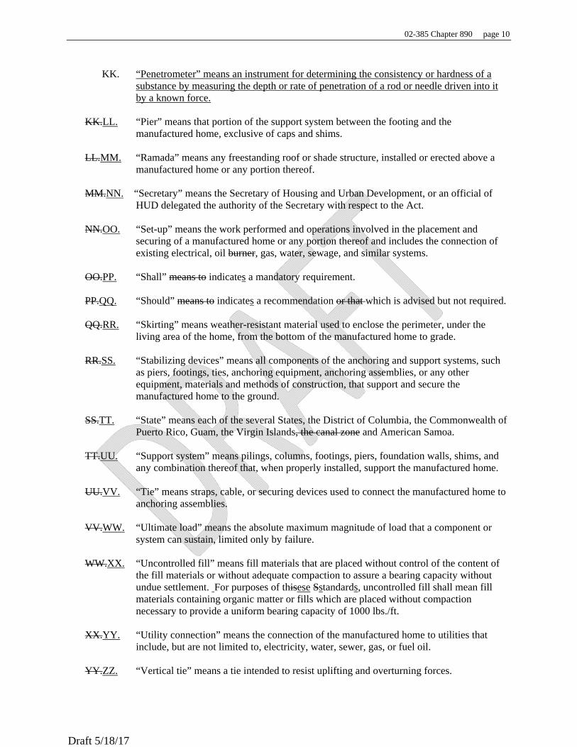
KK. “Penetrometer” means an instrument for determining the consistency or hardness of a substance by measuring the depth or rate of penetration of a rod or needle driven into it by a known force.
KK.LL. “Pier” means that portion of the support system between the footing and the
manufactured home, exclusive of caps and shims.
LL.MM. “Ramada” means any freestanding roof or shade structure, installed or erected above a manufactured home or any portion thereof.
MM.NN. “Secretary” means the Secretary of Housing and Urban Development, or an official of
HUD delegated the authority of the Secretary with respect to the Act.
NN.OO. “Set-up” means the work performed and operations involved in the placement and securing of a manufactured home or any portion thereof and includes the connection of existing electrical, oil burner, gas, water, sewage, and similar systems.
OO.PP. “Shall” means to indicates a mandatory requirement.
PP.QQ. “Should” means to indicates a recommendation or that which is advised but not required.
QQ.RR. “Skirting” means weather-resistant material used to enclose the perimeter, under the
living area of the home, from the bottom of the manufactured home to grade.
RR.SS. “Stabilizing devices” means all components of the anchoring and support systems, such as piers, footings, ties, anchoring equipment, anchoring assemblies, or any other equipment, materials and methods of construction, that support and secure the manufactured home to the ground.
SS.TT. “State” means each of the several States, the District of Columbia, the Commonwealth of
Puerto Rico, Guam, the Virgin Islands, the canal zone and American Samoa.
TT.UU. “Support system” means pilings, columns, footings, piers, foundation walls, shims, and any combination thereof that, when properly installed, support the manufactured home.
UU.VV. “Tie” means straps, cable, or securing devices used to connect the manufactured home to
anchoring assemblies.
VV.WW. “Ultimate load” means the absolute maximum magnitude of load that a component or system can sustain, limited only by failure.
WW.XX. “Uncontrolled fill” means fill materials that are placed without control of the content of
the fill materials or without adequate compaction to assure a bearing capacity without undue settlement. For purposes of thisese Sstandards, uncontrolled fill shall mean fill materials containing organic matter or fills which are placed without compaction necessary to provide a uniform bearing capacity of 1000 lbs./ft.
XX.YY. “Utility connection” means the connection of the manufactured home to utilities that
include, but are not limited to, electricity, water, sewer, gas, or fuel oil.
YY.ZZ. “Vertical tie” means a tie intended to resist uplifting and overturning forces.

02-385 Chapter 890 page 11
Draft 5/18/17
ZZ.AAA. “Wind zone” means the areas designated on the Basic Wind Zone Map, as further defined
in Appendix A to this chapter.
AAA.BBB. “Working load” means the maximum recommended load that may be exerted on a component or system determined by dividing the ultimate load of a component or system by an appropriate factor of safety.
VI. Final Leveling of Manufactured Home
Refer to Subchapter J.
VII. Preoccupancy Inspections A. Generally
Board staff will conduct pre-occupancy inspections of 230% of all new manufactured homes installed in Maine. The 230% will be selected randomly from locations throughout the state. For homes that pass inspection, a labelseal will be affixed underin the kitchen sink cabinet certifying that the installation compliedcompliance with thisthese manufactured home installation standards. For homes that do not pass inspection, a notice of violation and order of correction will be issued to the manufacturer, dealer or mechanic who performed the installation in the manner described in Chapter 370, Section 5(A) of the bBoard’s rules. The licensee shall respond to the notice of violation and order of correction as set forth in Chapter 370, and the provisions of Chapter 370 shall apply to any further proceedings arising from the notice of violation and order of correction. For purposes of this chapter, model homes are considered new homes asif they have never been occupied.
B. Emailing Purchase Information to Board
A dealer shall email the following information to the executive director of the bBoard immediately after receiving an order for manufactured housing from a purchaser: 1. The name and address of the dealer; 2. The manufacturer of the home; 3. The serial number of the home; 4. The estimated date of delivery; 5. The name of the purchaser; and 6. The anticipated physical address of the home. NOTE: The current email address of the executive director is — [email protected] -.
C. Response from Board

02-385 Chapter 890 page 12
Draft 5/18/17
The bBoard will respond by email to the dealer. The response will state whether or not the home reported by the dealer has been selected for pre-occupancy inspection.
D. Inspection
If the home has been selected for pre-occupancy inspection, the dealer shall notify the executive director of the Board by email when the home is installed and ready for occupancy, but prior to actual occupancy. The bBoard will then coordinate a date and time for the pre-occupancy inspection with the dealer. The bBoard will use its best efforts to perform the pre-occupancy inspection within 5 business days after receipt of notice from the dealer. The dealer shall be present at the pre-occupancy inspection. If the home passes inspection, the seal will be affixed by the inspector at the conclusion of the inspection and a copy of the inspection report will be mailed to the dealer.
E. Fee
The fee for the pre-occupancy inspection is established by the Director of the Office of Professional and Occupational Regulation and appears in Chapter 10, Section 5(24) of the rules of the Office of Professional and Occupational Regulation, entitled “Establishment of License Fees.” The bBoard will bill the dealer for the fee. The dealer shall pay the fee within 30 days of receipt. Failure to timely pay the fee will result in disciplinary action against the dealer.
SUBCHAPTER B-–PRE-INSTALLATION CONSIDERATIONS I. Fire Separation
No portion of a manufactured home, excluding the hitch, shall be located closer than 10 feet (3 meters) side to side, 8 feet (2.4 meters) end to side, or 6 feet (1.8 meters) end to end horizontally from any other manufactured home or community building unless the exposed composite walls and roof of either structure are without openings and constructed of materials that will provide a 1 hour fire-resistance rating or the structures are separated by a 1 hour fire-rated barrier.
II. Installation of Manufactured Homes in Flood Hazard Areas
A. Definitions Except to the extent otherwise in Subchapter A, the terms used in this subchapter are as defined in 44 CFR 59.1 of the National Flood Insurance Program (NFIP) regulations.
B. Applicability
The provisions of this section apply to the initial installation of new manufactured homes located wholly or partly within the flood hazard area.
C. Pre-Installation Considerations
Prior to the initial installation of a new manufactured home, the installer is responsible for determining whether the manufactured home site lies wholly or partly within a special flood hazard area as shown on the LAHJ’s Flood Insurance Rate Map, Flood Boundary

02-385 Chapter 890 page 13
Draft 5/18/17
and Floodway Map, or Flood Hazard Boundary Map, or if no LAHJ, in accordance with NFIP regulations. If so located, and before an installation method is agreed upon, the map and supporting studies adopted by the LAHJ must be used to determine the flood hazard zone and base flood elevation at the site.
D. General Elevation and Foundation Requirements
1. Methods and Practices Manufactured homes located wholly or partly within special flood hazard areas must be installed on foundations engineered to incorporate methods and practices that minimize flood damage during the base flood, in accordance with the LAHJ, 44 CFR 60.3(a) through (e) and other provisions of 44 CFR referenced by those paragraphs.
2. Outside Appliances
a. Appliances installed on the manufactured home site in flood hazard areas must be anchored and elevated to or above the same elevation as the lowest elevation of the lowest floor of the home.
b. Appliance air inlets and exhausts in flood hazard areas must be located at
or above the same elevation as the lowest elevation of the lowest floor of the home.
3. Related guidance
Refer to FEMA 85/September 1985, Manufactured Home and Installation in Flood Hazard Areas (incorporated by reference).
III. Site Suitability with Design Zone Maps
Prior to the initial installation of a new manufactured home and as part of making the certification of the installation required under part 3286 of the Federal standards, upon effect, the installer is to verify that the design and construction of the manufactured home, as indicated on the design zone maps provided with the home, are suitable for the site location where the home is to be installed. The design zone maps are those identified in part 3280 of the Federal standards.
A. Wind Zone
Manufactured homes must not be installed in a wind zone that exceeds the design wind loads for which the home has been designed, as evidenced by the wind zone indicated on the home’s data plate. Maine wind zones are described in Appendix A to this chapter.
B. Roof Load Zone
Manufactured homes must not be located in a roof load zone that exceeds the design roof load for which the home has been designed as evidenced by the roof load zone indicated on the home’s data plate. Maine roof load zones are described in Appendix A to this chapter.

02-385 Chapter 890 page 14
Draft 5/18/17
C. Thermal Zone
Manufactured Homes must not be installed in a thermal zone that exceeds the thermal zone for which the home has been designed as evidenced by the thermal zone indicated on the heating/cooling certificate and insulation zone map. The manufacturer may provide the heating/cooling information and insulation zone map on the home’s data plate.
IV. Permits, OtherAlterations, and On-Site Structures Refer to Subchapter J for considerations related to permitting, other alterations and on-site
structures. SUBCHAPTER C – SITE PREPARATION I. Soil Conditions To help prevent settling or sagging, the foundation must be constructed on firm, undisturbed soil
or fill compacted to at least 90 percent of its maximum relative density. All organic material such as grass, roots, twigs, and wood scraps must be removed in areas where footings are to be placed. After removal of organic material, the home site must be graded or otherwise prepared to ensure adequate drainage, in accordance with Subchapter C, Section III. Homes shall not be installed on uncontrolled fill.
II. Soil Classifications and Bearing Capacity
The soil classification and bearing capacity of the soil must be determined before the foundation is constructed and anchored. The soil classification and bearing capacity must be determined by one or more of the following methods, unless the soil bearing capacity is established as permitted in pParagraph F of this Ssection:
A. Soil Test. Soil tests that are in accordance with generally accepted engineering practice; or
B. Soil Records. Soil records of the applicable LAHJ; or
C. Soil classifications and bearing capacities. If the soil class or bearing capacity cannot be
determined by test or soil records, but its type can be identified, the soil classification, allowable pressures, and torque values shown in the table to this section may be used.
D. A pocket penetrometer; or
E. In lieu of determining the soil bearing capacity by use of the methods shown in the table,
an allowable pressure of 1,500 psf may be used, unless the site-specific information requires the use of lower values based on soil classification and type.
F. If the soil appears to be composed of peat, organic clays or uncompacted fill, or appears
to have unusual conditions, a registered professional geologist, registered professional engineer, or registered architect must determine the soil classification and maximum allowable soil bearing capacity.

02-385 Chapter 890 page 15
Draft 5/18/17
Table to Subchapter C, Section II – Soil Classifications and Bearing Capacity ASTM D 2487–00 or D 2488–00, (incorporated by reference)
Soil classification Soil description
Allowable soil bearing pressure (psf)1
Blow count ASTM D 1586–99
Torque probe3 value4 (inch-
pounds) Classification number
1 ................ .................................. Rock or hard pan ....................................... 4000+ .......................
2 ................ GW, GP, SW, SP, GM, SM.
Sandy gravel and gravel; very than dense and/or cemented sands; course gravel/ cobbles; preloaded silts, clays and coral.
2000 ......................... 40+ More than 550.
3 ................ GC, SC, ML, CL ...... Sand; silty sand; clayey sand; silty gravel; medium dense course sands; sandy gravel; and very stiff silt, sand clays.
1500 ......................... 24–39 351–550.
4A .............. CG, MH2................. Loose to medium dense sands; firm to stiff clays and silts; alluvial fills.
1000 ......................... 18–23 276–350.
4B .............. CH, MH2.................. Loose sands; firm clays; alluvial fills ......... 1000 ......................... 12–17 175–275. 5 ................ OL, OH, PT ............. Uncompacted fill; peat; organic clays ....... Refer to Subchapter C
Section II(EF) 0–11 Less than 175.
Notes to Table 1. The values provided in this table have not been adjusted for overburden pressure, embedment depth, water table height, or settlement problems. 2. For Soils classified as CH or MH, without either torque probe values or blow count test results, selected anchors must be rated for a 4B soil. 3. The torque test probe is a device for measuring the torque probe value of soils to assist in evaluating the holding capacity of the soil in which the ground
anchor is placed. The shaft must be of suitable length for the full depth of the ground anchor. 4. The torque value is a measure of the load resistance provided by the soil when subject to the turning or twisting force of the probe.
III. Site Drainage
A. Purpose
Drainage must be provided to direct surface water away from the home to protect against erosion of foundation supports and to prevent water build-up under the home, as shown in the Figure to Subchapter C, Section III – Site Drainage.
B. The home site must be graded as shown in the Figure to Subchapter C, Section III –- Site Drainage, or other methods, such as a drain tile and automatic sump pump system, must be provided to remove any water that may collect under the home.
C. All drainage must be diverted away from the home and must slope a minimum of one-
half inch per foot away from the foundation for the first 10ten feet. Where property lines, walls, slopes, or other physical conditions prohibit this slope, the site must be provided with drains or swales or otherwise graded to drain water away from the structure as shown in the Figure 1 to Subchapter C, Section III – Site Drainage.
D. Sloped Site Considerations
The home, where sited, must be protected from surface runoff from the surrounding area.

02-385 Chapter 890 page 16
Draft 5/18/17
E. Gutters and Downspouts
Manufacturers must specify in their installation instructions whether the home is suitable for the installation of gutters and downspouts. If suitable, the installation instructions must indicate that when gutters and downspouts are installed, the runoff must be directed away from the home. Figure to Subchapter C, Section III – Site Drainage

02-385 Chapter 890 page 17
Draft 5/18/17
IV. Ground Moisture Control
A. Vapor Retarder
If the space under the home is to be enclosed with skirting or other materials, a vapor retarder must be installed to cover the ground under the home.
B. Vapor Retarder Material
A minimum of six mil polyethylene sheeting or its equivalent must be used.
C. Proper Installation
1. The entire area under the home must be covered with the vapor retarder as noted in pParagraph A of this section, except for areas under open porches, decks, and recessed entries. Joints in the vapor retarder must be overlapped at least 12 inches.
2. The ground covervapor retarder may be placed directly beneath footings, or
otherwise installed around or over footings placed at grade, and around anchors or other obstructions.
3. Any voids or tears in the vapor retarder must be repaired. At least one repair
method must be provided in the manufacturer’s installation instructions. SUBCHAPTER D -– FOUNDATIONS I. General A. Foundations for manufactured home installations must be designed and constructed in
accordance with this subchapter and must be based on site conditions, home design features, and the loads the home was designed to withstand, as shown on the home’s data plate.
B. Foundation systems that are not pier and footing type configurations may be used when
verified by engineering data and designed in accordance with Subchapter D, Section I(D), consistent with the design loads of the MHCSS. Pier and footing specifications that are different than those provided in this subchapter, such as block size, metal piers, section width, loads, and spacing, may be used when verified by engineering data and comply with Subchapter D, Section I(C) and (D) and are capable of resisting all design loads of the MHCSS.
C. All foundation details, plans, and test data must be designed and certified by a registered
professional engineer or registered architect, and must not take the home out of compliance with the MHCSS.
D. Alternative foundation systems or designs are permitted in accordance with either of the
following: 1. Systems or designs must be manufactured and installed in accordance with their
listings by a nationally recognized testing agency based on a nationally recognized testing protocol; or

02-385 Chapter 890 page 18
Draft 5/18/17
2. System designs must be prepared by a registered professional engineer or a registered
architect in accordance with acceptable engineering practice and must be installed so as not to take the home out of compliance with the MHCSS (part 3280).
II. Flood Hazard Areas In flood hazard areas, foundations, anchorings, and support systems must be capable of resisting
loads associated with design flood and wind events, or combined wind and flood events, and homes must be installed on foundation supports that are designed and anchored to prevent flotation, collapse, or lateral movement of the structure. Manufacturer’s installation instructions must indicate whether:
A. The foundation specifications have been designed for flood-resistant considerations, and,
if so, the conditions of applicability for velocities, depths, or wave action; or
B. The foundation specifications are not designed to address flood loads.
III. Piers A. General
The piers used must be capable of transmitting the vertical live and dead loads to the footings or foundation.
B. Acceptable Piers – Materials Specification
1. Piers are permitted to be concrete blocks, pressure-treated wood with a water borne preservative, in accordance with AWPA Standard U1-04 (incorporated by reference) for Use Category 4B ground contact applications; or adjustable metal or concrete piers.
2. Manufactured piers must be listed or labeled for the required vertical load
capacity, and, where required by design, for the appropriate horizontal load capacity.
C. Design Requirements
1. Load-bearing capacity
The load-bearing capacity for each pier must be designed to include consideration for the dimensions of the home, the design dead and live loads, the spacing of the piers, and the way the piers are used to support the home.
2. Center beam/mating wall support must be required for multi-section homes and
designs must be consistent with Tables 2 and 3 of this section and Figures A, B, and C to Subchapter D, Section X.

02-385 Chapter 890 page 19
Draft 5/18/17
D. Pier Loads
1. Design support layout configurations for the pier loads, pier spacing, and roof live loads must be in accordance with Tables 1, 2 and 3 of this section and the MHCSS. Other pier designs are permitted in accordance with this subchapter.
2. Manufactured piers must be rated at least to the loads required to safely support
the dead and live loads, as required by Subchapter D, Section I, and the installation instructions for those piers must be consistent with Tables 1, 2, and 3 of this section.
Table 1 to Subchapter D, Section III – Piers
Frame Blocking Only – Perimeter Support not Required Except at Openings
Notes to Table 1: 1. See the Table to Subchapter D, Section XII for cast-in-place footing design by using the noted loads. 2. Table 1 is based on the following design assumptions: maximum 16 ft. nominal section width (15 ft. actual width), 12” eave, 10”
I-beam size, 300 lbs. pier dead load, 10 psf roof dead load, 6 psf floor dead load, 35 plf wall dead load, and 10 plf chassis dead load. 3. Interpolation for other pier spacing is permitted. 4. The pier spacing and loads shown in the above table do not consider floor or seismic loads, and are not intended for use in flood or seismic hazard areas.
In those areas, the foundation support system is to be designed by a professional engineer or architect. 5. See the Table to Subchapter D, Section XII for sizing of footings.
Pier spacing
Roof live load (psf)
Location Load (lbs.)
4 ft. 0 in. .......................................... 20 30 40
Frame .................................................................. Frame .................................................................. Frame ..................................................................
2,900 3,300 3,600
6 ft. 0 in. ........................................... 20 30 40
Frame .................................................................. Frame .................................................................. Frame ..................................................................
4,200 4,700 5,200
8 ft. 0 in. ............................................ 20 30 40
Frame .................................................................. Frame .................................................................. Frame ..................................................................
5,500 6,200 6,900
10 ft. 0 in. ............................................ 20 30 40
Frame .................................................................. Frame .................................................................. Frame ..................................................................
6,800 7,600 8,500

02-385 Chapter 890 page 20
Draft 5/18/17
Table 2 to Subchapter D, Section III – Piers Frame Plus Perimeter Blocking/Perimeter Blocking Required
Notes to Table 2: 1. See the Table to Subchapter D, Section XII for cast-in-place footing design by using the noted loads. 2. Mating wall perimeter piers and footings only required under full height mating walls supporting roof loads. Refer to Figures 1A and 2B to Subchapter D,
Section X. 3. Table 2 is based on the following design assumptions: maximum 16 ft. nominal section width (15 ft. actual width), 12” eave, 10” I-beam size, 300 lbs. pier
dead load, 10 psf roof dead load, 6 psf floor dead load, 35 plf wall dead load, and 10 plf chassis dead load. 4. Interpolation for other pier spacing is permitted. 5. The pier spacing and loads shown in the above table do not consider floor or seismic loads and are not intended for use in flood or seismic hazard areas.
In those areas, the foundation support system is to be designed by a professional engineer or architect. 6. See the Table to Subchapter D, Section XII for sizing of footings.
Maximum pier spacing Roof live load (psf)
Location Load (lbs.)
4 ft. 0 in. ....................................................................... 20 Frame ........................................................................... Perimeter ...................................................................... Mating ...........................................................................
1,400 1,900 3,200
4 ft. 0 in. ....................................................................... 30 Frame ........................................................................... Perimeter ...................................................................... Mating ...........................................................................
1,400 2,300 3,800
4 ft. 0 in. ....................................................................... 40 Frame ........................................................................... Perimeter ...................................................................... Mating ...........................................................................
1,400 2,600 4,400
6 ft. 0 in. ....................................................................... 20 Frame ........................................................................... Perimeter ...................................................................... Mating ...........................................................................
1,900 2,700 4,700
6 ft. 0 in. ....................................................................... 30 Frame ........................................................................... Perimeter ...................................................................... Mating ...........................................................................
1,900 3,200 5,600
6 ft. 0 in. ....................................................................... 40 Frame ........................................................................... Perimeter ...................................................................... Mating ...........................................................................
1,900 3,700 6,500
8 ft. 0 in. ....................................................................... 20 Frame ........................................................................... Perimeter ...................................................................... Mating ...........................................................................
2,400 3,500 6,100
8 ft. 0 in. ....................................................................... 30 Frame ........................................................................... Perimeter ...................................................................... Mating ...........................................................................
2,400 4,200 7,300
8 ft. 0 in. ....................................................................... 40 Frame ........................................................................... Perimeter ...................................................................... Mating ...........................................................................
2,400 4,800 8,500
10 ft. 0 in. ..................................................................... 20 Frame ........................................................................... Perimeter ...................................................................... Mating ...........................................................................
2,900 4,300 7,600
10 ft. 0 in. ..................................................................... 30 Frame ........................................................................... Perimeter ...................................................................... Mating ...........................................................................
2,900 5,100 9,100
10 ft. 0 in. ..................................................................... 40 Frame ........................................................................... Perimeter ...................................................................... Mating ...........................................................................
2,900 6,000 10,600

02-385 Chapter 890 page 21
Draft 5/18/17
Table 3 to Subchapter D, Section III – Piers Ridge Beam Span Footing Capacity
Notes to Table 3: 1. See the Table to Subchapter D, Section XII for cast-in-place footing design by
using the noted loads. 2. Table 3 is based on the following design assumptions: maximum 16 ft. nominal
section width (15 ft. actual width), 12” eave, 10” I-beam size, 300 lbs. pier dead load, 10 psf roof dead load, 6 psf floor dead load, 35 plf wall dead load, and 10 plf chassis dead load.
3. Loads listed are maximum column loads for each section of the manufactured home.
4. Interpolation for maximum allowable pier and column loads is permitted for mate-line openings between those shown in the table.
5. The pier spacing and loads shown in the above table do not consider flood or seismic loads, and are not intended for use in flood or seismic hazard areas. In those areas, the foundation support system is to be designed by a professional engineer or architect.
6. See the Table to Subchapter D, Section XII for sizing of footings.
IV. Pier Configuration
A. Concrete Blocks
Installation instructions for concrete block piers must be developed in accordance with the following provisions and must be consistent with Figures 1A and 2B to Subchapter D, Section VI: 1. Load-bearing (not decorative) concrete blocks must have nominal dimensions of
at least 8 inches x 8 inches x 16 inches;
2. The concrete blocks must be stacked with their hollow cells aligned vertically; and 3. When piers are constructed of blocks stacked side by side, each layer must be at right
angles to the preceding one, as shown in Figure 2B to Subchapter D, Section VI.
B. Caps 1. Structural loads must be evenly distributed across capped-hollow block piers, as
shown in Figures 1A and 2B to Subchapter D, Section VI. 2. Caps must be solid concrete or masonry of at least 4 inches nominal in thickness,
or hardboard lumber at least 2 inches nominal in thickness, or be of corrosion-protected minimum one-half inch thick steel, or be of other listed materials.
3. All caps must be of the same length and width as the piers on which they rest.
Mating wall opening (ft)
Roof live load (psf)
Pier and footing load (lbs.)
5 ................ 20 30 40
1,200 1,600 1,900
10 .............. 20 30 40
2,300 3,100 3,800
15 .............. 20 30 40
3,500 4,700 5,800
20 .............. 20 30 40
4,700 6,200 7,500
25 .............. 20 30 40
5,800 7,800 9,700
30 .............. 20 30 40
7,000 9,300 11,600
35 .............. 20 30 40
8,100 10,900 13,600
02-385 Chapter 890 page 22
Draft 5/18/17
4. When split caps are used on double stacked blocks, the caps must be installed
with the long dimension across the joint in the blocks below.
C. Gaps
Any gaps that occur during installation between the bottom of the main chassis beam and foundation support system must be filled by:
1. Nominal 4 inch x 6 inch x 1 inch shims to level the home and fill any gaps
between the base of the main chassis beam and the top of the pier cap; 2. Shims must be used in pairs as shown in Figures 1A and 2B to Subchapter D,
Section VI, and must be driven in tightly so that they do not occupy more than one inch of vertical height; and
3. Hardwood plates no thicker than 2 inches nominal in thickness or 2 inch or 4
inch nominal concrete block must be used to fill in remaining vertical gaps.
D. Manufactured Pier Heights
Manufactured pier heights must be selected so that the adjustable risers do not extend more than 2 inches when finally positioned.
V. Clearance under Homes A minimum clearance of 12 inches must be maintained between the lowest member of the main frame (I-beam or channel beam) and the grade under all areas of the home.
VI. Design Procedures for Concrete Block Piers
A. Frame piers less than 36 inches high
1. Frame piers less than 36 inches high are permitted to be constructed of single, open or closed-cell concrete blocks 8 inches x 8 inches x 16 inches, when the design capacity of the block is not exceeded.
2. The frame piers must be installed so that the long sides are at right angles to the
supported I-beam, as shown in Figure 1A of this section.
3. The concrete blocks must be stacked with their hollow cells aligned vertically and must be positioned at right angles to the footings.
4. Horizontal offsets from the top to the bottom of the pier must not exceed one-
half inch.
5. Mortar is not required, unless specified in the installation instructions or required by a registered professional engineer or registered architect.

02-385 Chapter 890 page 23
Draft 5/18/17
B. Frame Piers 36 inches to 4867 inches high and Corner Piers
1. All frame piers between 36 inches and 4867 inches high and all corner piers over three blocks high must be constructed out of double, interlocked concrete blocks, as shown in Figure B to this section, when the design capacity of the block is not exceeded. Mortar is not required for concrete piers, unless otherwise specified in the manufacturer installation instructions or required by a registered professional engineer or registered architect.
2. Horizontal offsets from the top to the bottom of the pier must not exceed one inch.
C. All Piers over 4867 inches High
Piers over 4867 inches high must be designed by a registered professional engineer or registered architect, in accordance with acceptable engineering practice. Mortar is not required for concrete block piers unless otherwise specified in the manufacturer installation instructions or by the design.
Figure A to Subchapter D, Section VI – Design Procedures for Pier Concrete Blocks Piers:
Typical Footing and Pier Design, Single Concrete Block

02-385 Chapter 890 page 24
Draft 5/18/17
Figure B to Subchapter D, Section VI – Design Procedures for Concrete Pier Blocks Piers: Typical Footing and Pier Installation, Double Concrete Block
Main I-beam frame
36 inches to max 4867 inches in height In freezing climates, the footing must extend Typical footing. Solid concrete or other product below the frost line or be otherwise protected listed for the purpose. Footing is placed on firm, from the effects of frost heave as permitted undisturbed soil or controlled fill, free of grass herein. and organic matter.
VII. Perimeter Support Piers A. Piers required at mate-line supports, perimeter piers, and piers at exterior wall openings
are permitted to be constructed of single open-cell or closed-cell concrete blocks, with nominal dimensions of 8 inches x 8 inches x 16 inches, to a maximum height of 4854 inches as shown in Figure A to this section, when the design capacity of the block is not exceeded.
B. Piers used for perimeter support must be installed with the long dimension parallel to the
perimeter rail.
VIII. Manufactured Piers
A. Manufactured piers must be listed and labeled and installed to the pier manufacturer’s installation instructions. See Subchapter D, Section III(D)(2) for additional requirements.
B. Metal or other manufactured piers must be provided with protection against weather
deterioration and corrosion at least equivalent to that provided by a coating of zinc on steel of .30 oz./ft2 of surface coated.

02-385 Chapter 890 page 25
Draft 5/18/17
IX. [Reserved] X. Pier Location and Spacing A. The location and spacing of piers depends upon the dimensions of the home, the live and
dead loads, the type of construction (single-or multi-section), I-beam size, soil bearing capacity, footing size, and such other factors as the location of doors or other openings.
B. Mate-line and column pier supports must be in accordance with this subchapter and
consistent with Figures A through C of this section unless the pier support and footing configuration is designed by a registered professional engineer or registered architect.
C. Piers supporting the frame must be no more than 24 inches from both ends and not more
than 120 inches center to center under the main rails. D. Pier support locations and spacing must be presented to be consistent with Figures A and
B to Subchapter D, Section XII, as applicable, unless alternative designs are provided by a registered professional engineer or registered architect in accordance with acceptable engineering practice.
Figure A to Subchapter D, Section X – Pier Location and Spacing:
Typical Mate-Line Column Pier and Mating Wall Support When Frame Only Blocking is Required
Footings sized for single spans C and D to support the Pier and Footing Load indicated in Table 3 to Subchapter D, Section III. [Note: If wall is less than 16” in width use combined span C+D, single pier.]
Footing sized for span B or C, as applicable, to support the Pier and Footing Load indicated in Table 3 to Subchapter D, Section III.
Footings sized for combined spans A+B to support the Pier and Footing Load indicated in Table 3 to Subchapter D, Section III(D).
Footing sized for span A to support the Pier and Footing Load indicated in Table 3 to Subchapter D, Section III(D).
Notes to Figure A: 1. Bottom of footings must extend below frost line depth, unless designed for placement above the frost lines. (See Subchapter D,
Section XII(B)). 2. Piers may be offset up to 6 inches in either direction along the supported members to allow for plumbing, electrical,
mechanical, equipment, crawlspace, or other devices. 3. Single-stack concrete block pier loads must not exceed 8,000 lbs. 4. Prefabricated piers must not exceed their approved or listed maximum vertical or horizontal design loads. 5. When a full-height mating wall does not support the ridge beam, this area is considered an unsupported span – Span B.

02-385 Chapter 890 page 26
Draft 5/18/17
6. Piers are not required at openings in the mating wall that are less than 48 inches in width. Place piers on both sides of mating wall openings that are 48 inches or greater in width. For roof loads of 40 psf or greater, a professional engineer or registered architect must determine the maximum mating wall opening permitted without pier or other supports.
Figure B to Subchapter D, Section X – Pier Location & Spacing:
Typical Mate-Line Column Pier and Mating Wall Support When Perimeter Blocking is Required
See Note 1
Footing sized & spaced to support the Load indicated in Table 2 to Subchapter D, Section III(D).
Footing sized for span C to support the Load indicated in Table 2 to Subchapter D, Section III(D).
Footing sized & spaced to support the Load indicated in Table 2 to Subchapter D, Section III(D).
Footing sized for span B to support the Pier & Footing Load indicated in Table 3 to Subchapter D, Section III(D).
Footing sized for combined span A+B to support the pPier & fFooting lLoad indicated in Table 3 to Subchapter D, Section III(D).
See Note 6
Footing sized for span A to support the pPier & fFooting lLoad indicated in Table 3 to Subchapter D, Section III(D).
Notes to Figure B: 1. Bottom of footings must be below the frost line depth, unless designed for placement above the frost line. (See Subchapter D,
Section XII(B)). 2. Piers may be offset 6 inches in either direction along supported members to allow for plumbing, electrical, mechanical
equipment, crawlspace, or other devices. 3. Single stack concrete blocks pier loads must not exceed 8,000 lbs. 4. Piers are not required at openings in the mating wall that are less than 48 inches in width. Place piers on both sides of mating
wall openings that are 48 inches or greater in width. For roof loads of 40 psf or greater, a professional engineer or registered architect must determine the maximum mating wall opening permitted without pier or other supports.
5. When a full-height mating wall does not support the ridge beam, this area is considered an unsupported span – Span B. 6. In areas where the open span is greater than 10 ft., intermediate piers and footings must be placed at maximum 10 ft. on center. 7. Prefabricated piers must not exceed their approved or listed maximum horizontal or vertical design loads. 8. Column piers are in addition to piers required under full-height mating walls.
Figure C to Subchapter D, Section X – Pier Location & Spacing: Typical Mate-Line Column and Piers Notes to Figure C: 1. Mate-line column supports piers are installed with the long dimension
of the concrete block perpendicular to the rim joists. 2. Pier and footing designed to support both floor sections. Loads as listed in
Table 3 to Subchapter D, Section III are total column loads for both sections.

02-385 Chapter 890 page 27
Draft 5/18/17
XI. Required Perimeter Supports A. Perimeter pier or other supports must be located as follows: 1. On both sides of side wall exterior doors (such as entry, patio, and sliding glass
doors) and any other side wall openings of 48 inches or greater in width, and under load-bearing porch posts, factory installed fireplaces, and fireplace stoves.)
2. Other perimeter supports must be:
a. Located in accordance with Table 2 to Subchapter D, Section III; or b. Provided by other means such as additional outriggers or floor joists.
When this alternative is used, the design required by Subchapter D, Section I must consider the additional loads in sizing the pier and footing supports under the main chassis beam.
B. For roof live rloads of 40 psf or greater, a professional registered engineer or professional
architect must determine the maximum sidewall opening permitted without perimeter pier or other supports.
C. The location and installation of any perimeter pier support must not take the home out of
compliance with the Manufactured Home Construction and Safety Standards (part 3280).
XII. Footings A. Materials approved for footings must provide equal load-bearing capacity and resistance
to decay, as required by this section. Footings must be placed on undisturbed soil or fill compacted to 90 percent of maximum relative density. A footing must support every pier. Footings are to be either:
1. Concrete
a. Four inch nominal precast concrete pads meeting or exceeding ASTM C 90-02a, Standard Specification for Loadbearing Concrete Masonry Units (incorporated by reference), without reinforcement, with at least a 28-day compressive strength of 1,200 pounds per square inch (psi); or
b. Six inch nominal poured-in-place concrete pads, slabs, or ribbons with at
least a 28-day compressive strength of 3,000 pounds per square inch (psi). Site-specific soil conditions or design load requirements may also require the use of reinforcing steel in cast-in-place concrete footings.

02-385 Chapter 890 page 28
Draft 5/18/17
2. Pressure-treated permanent wood
a. Pressure-treated wood footings must consist of a minimum of two layers of nominal 2-inch thick pressure treated wood, a single layer of nominal ¾-inch thick, pressure-treated plywood with a maximum size of 16 inches by 16 inches, or at least two layers of ¾-inch thick, pressure-treated plywood for sizes greater than 16 inches by 16 inches. Plywood used for this purpose is to be rated exposure 1 or exterior sheathing, in accordance with PS1-95, Construction and Industrial Plywood (incorporated by reference).
b. Pressure-treated lumber is to be treated with a water-borne adhesive, in
accordance with AWPA Standard U1-04 (incorporated by reference) for Use Category 4B ground contact applications.
c. Cut ends of pressure treated lumber must be field-treated, in
accordance with AWPA Standard M4-02 (incorporated by reference).
3. ABS footing pads
a. ABS footing pads are permitted provided they are installed in accordance with the pad manufacturer installation instructions and certified for use in the soil classification at the site.
b. ABS footing pads must be listed or labeled for the required load
capacity.
4. Other materials Footings may be of other materials than those identified in this section,
provided they are listed for such use and meet all other applicable requirements of this subchapter.
B. Placement in Freezing Climates
Footings placed in freezing climates must be designed using methods and practices that prevent the effects of frost heave by one of the following methods: 1. Conventional footings
Conventional footings must be placed below the frost line depth for the site unless an insulated foundation or monolithic slab is used (refer to Subchapter D, Section XII(CB)(2) and Subchapter D, Section XII(CB)(3)). When the frost line depth is not available from the LAHJ, a registered professional engineer, registered architect, or registered geologist must be consulted to determine the required frost line depth for the manufactured home site. This is not subject to the provisions in Subchapter A, Section II(C) that also require review by the manufacturer and approval by its DAPIA for any variations to the manufacturer’s installation instructions for support and anchoring.

02-385 Chapter 890 page 29
Draft 5/18/17
2. Monolithic slab systems
A monolithic slab is permitted above the frost line when all relevant site-specific conditions, including soil characteristics, site preparation, ventilation, and insulative properties of the under floor enclosure are considered and anchorage requirements are accommodated as set out in Subchapter E, Section I. The monolithic slab system must be designed by a registered professional engineer or registered architect:
a. In accordance with acceptable engineering practice to prevent the effects
of frost heave; or
b. In accordance with SEI/ASCE 32-01 (incorporated by reference).
3. Insulated foundations
An insulated foundation is permitted above the frost line, when all relevant site-specific conditions, including soil characteristics, site preparation, ventilation, and insulative properties of the under the floor enclosure, are considered, and the foundation is designed by a registered professional engineer or registered architect: a. In accordance with acceptable engineering practice to prevent the effects
of frost heave; or
b. In accordance with SEI/ASCE 32-01 (incorporated by reference).
C. Sizing of footings
The sizing and layout of footings depends on the load-bearing capacity of the soil, footings, and the piers. -See Subchapter C, Sections II and III, and Table to Subchapter D, Section XII.
Figure A to Subchapter D, Section XII – Footings
Typical Blocking Diagram for Single Section Homes
Notes to Figure A: 1. Refer to Table 1 to Subchapter D, Section III for pier and footing requirements when frame blocking only is used. 2. In addition to blocking required by Subchapter D, Section XI, see Table 2 to Subchapter D, Section III for maximum perimeter
blocking loads.

02-385 Chapter 890 page 30
Draft 5/18/17
See Figures A and B to Subchapter D, Section X for typical pier and footing requirements along the mate lines of multi-section homes.
3. End piers under main I-beams may be set back a maximum of 24 inches, as measure from the outside edge of the floor to the center of the pier.
4. Place piers on both sides of sidewall exterior doors, patio doors, and sliding glass doors; under porch posts, factory-installed fireplaces, and fireplace stoves; under jamb studs at multiple window openings; and at any other sidewall openings 48 inches or greater in width. For roof loads of 40 psf or greater, a professional engineer or registered architect must determine the maximum sidewall opening permitted without perimeter supports. See Subchapter D, Section VII and Subchapter D, Section XI for additional requirements for locating perimeter supports.
Figure B to Subchapter D, Section XII – Footings Typical Blocking Diagram for Multi-section Homes
Notes to Figure B: 1. Refer to Table 1 to Subchapter D, Section III for pier and footing requirements when frame blocking only is used. 2. In addition to blocking required by Subchapter D, Section XI, see Tables 2 and 3 to Subchapter D, Section III for maximum
perimeter blocking loads. 3. End piers under main I-beams may be set back a maximum of 24 inches, as measured from the outside edge of the floor to
center of the pier. 4. Place piers on both sides of sidewall exterior doors, patio doors, and sliding glass doors; under porch posts, factory-installed
fireplaces, and fireplace stoves; under jamb studs at multiple window openings; and at any other sidewall openings 48 inches or greater in width. For roof loads of 40 psf or greater, a professional engineer or registered architect must determine the maximum sidewall opening permitted without perimeter supports or mating wall opening permitted without pier or other supports. See Subchapter D, Section VII and Subchapter D, Section XI for additional requirements for locating perimeter supports.
5. When an end pier under the mate-line also serves as a column pier, it may be set back a maximum of 6 inches, as measured from the inside edge of the exterior wall to the center of the pier.

02-385 Chapter 890 page 31
Draft 5/18/17
Table to Subchapter D, Section XII – Footings The Size & Capacity for Unreinforced Cast-in-Place Footings
Soil
capacity (psf)
Minimum footing
Size (in.)
8 in. x 16 in. pier 16 in. x 16 in. pier
Maximum footing capacity (lbs)
Unreinforced cast-in-place minimum thickness (in.)
Maximum footing capacity (lbs)
Unreinforced cast-in-place minimum thickness (in.)
1,000 16 x 16 1,600 6 1,600 6 20 x 20 2,600 6 2,600 6 24 x 24 3,700 6 3,700 6 30 x 30 5,600 8 5,800 6 36 x 36 7,900 10 8,100 8 42 x 42 4 10,700 10 10,700 10 48 x 48 4 13,100 12 13,600 10 1,500
16 x 16 2,500 6 2,500 6
20 x 20 4,000 6 4,000 6 24 x 24 5,600 8 5,700 6 30 x 30 4 8,500 10 8,900 8 36 x 36 4 12,400 10 12,600 8 42 x 42 4 16,500 12 416,800 10 48 x 48 4 21,200 14 421,600 12 2,000
16 x 16 3,400 6 3,400 6
20 x 20 5,300 6 5,300 6 24 x 24 7,600 8 7,700 6 30 x 30 4 11,700 10 11,900 8 36 x 36 4 16,700 15 4 16,900 10 42 x 42 4 21,700 18 4 22,700 12 2,500
16 x 16 4,300 6 4,300 6
20 x 20 6,700 6 6,700 6 24 x 24 4 9,600 8 9,700 6 30 x 30 4 14,800 10 15,000 8 36 x 36 4 20,700 12 4 21,400 10 3,000
16 x 16 5,200 6 5,200 6
20 x 20 8,100 8 8,100 6 24 x 24 4 11,500 10 11,700 6 30 x 30 4 17,800 12 4 18,100 8 36 x 36 4 25,400 14 4 25,900 10 4,000
16 x 16 7,000 6 7,000 6
20 x 20 4 10,800 8 10,900 6 24 x 24 4 15,500 10 15,600 8 30 x 30 4 23,300 12 4 24,200 10 Notes to Table: 1. The footing sizes shown are for square pads and are based on the area (in.2), shear and bending required for the loads shown. Other configurations, such
as rectangular or circular configurations, can be used, provided the area and depth is equal to or greater than the area and depth of the square footing shown in the table, and the distance from the edge of the pier to the edge of the footing is not less than the thickness of the footing.
2. The 6 inch cast-in-place values can be used for 4 inch unreinforced precast concrete footings. 3. The capacity values listed have been reduced by the dead load of the concrete footing. 4. Concrete block piers must not exceed their design capacity of 8,000 lbs for 8” x 16” single stack block and 16,000 lbs for 16” x 16” double stack block. 5. A registered professional engineer or registered architect must prepare the design, if the design loads exceed the capacity for single or double stack
concrete block piers shown in footnote 4.

02-385 Chapter 890 page 32
Draft 5/18/17
XIII. Combination Systems
Support systems that combine both load-bearing capacity and uplift resistance must also be sized and designed for all applicable design loads.
XIV. [Reserved] XV. Special Snow Load Conditions A. General Foundations for homes designed for and located in areas with roof live loads greater than
40 psf must be designed by the manufacturer for the special snow load conditions in accordance with acceptable engineering practice. Where site or other conditions, final determination to be made by the Manufactured Housing Board, prohibit the use of the manufacturer’s instructions, a registered professional engineer or registered architect must design the foundation for the special snow load conditions.
B. Ramadas Ramadas may be used in areas with roof live loads greater than 40 psf. Ramadas areshall
to be self-supporting, except any connection to the home mustshall be for weatherproofing only.
SUBCHAPTER E – ANCHORAGE AGAINST WIND I. Anchoring Instructions A. After blocking and leveling, the manufactured home mustshall be secured against the
wind by use of anchor assembly type installations or by connecting the home to an alternative foundation system. See Subchapter D, Section I.
B. For anchor assembly type installations, the installation instructions must require the home
to be secured against the wind as described in this section. The installation instructions and design for anchor type assemblies must be prepared by a registered professional engineer or registered architect, in accordance with acceptable engineering practice, the design loads of the MHCSS, and Subchapter D, Section I.
C. All anchoring and foundation systems must be capable of meeting the loads that the home
was designed to withstand required by part 3280 and Subchapter D, as shown on the home’s data plate.
Exception: Manufactured homes that are installed in less restrictive roof load zone and wind zone areas may have foundation or anchorage systems that are capable of meeting the lower design load provision of the Standards, if the design for the lower requirements is either provided in the installation instructions or the foundation and anchorage system is designed by a professional registered engineer or registered architect.
D. The installation instructions are to include at least the following information and details
for anchor assembly-type installation:

02-385 Chapter 890 page 33
Draft 5/18/17
1. The maximum spacing for installing diagonal ties and any required vertical ties or straps to ground anchors;
2. The minimum and maximum angles or dimensions for installing diagonal ties or
straps to ground anchors and the main chassis members of the manufactured home; 3. Requirements for connecting the diagonal ties to the main chassis members of the
manufactured home. If the diagonal ties are attached to the bottom flange of the main chassis beam, the frame must be designed to prevent rotation of the beam;
4. Requirements for longitudinal and mating wall tie-downs and anchorage; 5. The method of strap attachment to the main chassis member and ground anchor,
including provisions for swivel-type connections;
6. The methods for protecting vertical and diagonal strapping at sharp corners by use of radius clips or other means; and
7. As applicable, the requirements for sizing and installation of stabilizer plates.
II. Ground Anchor Installations
A. Ground Anchor Certification and Testing
Each ground anchor must be manufactured and provided with installation instructions, in accordance with its listing or certification. A nationally recognized testing agency must list, or a registered professional engineer or registered architect must certify, the ground anchor for use in a classified soil (refer to Subchapter C, Section II), based on a nationally recognized testing protocol, or a registered professional engineer or registered architect must certify that the ground anchor is capable of resisting all loads in pParagraph B of this section for the soil type or classification.
B. Specification for Tie-down Straps and Ground Anchors
1. Ground Anchors Ground anchors must be installed in accordance with their listing or certification,
be installed to their full depth, be provided with protection against weather deterioration and corrosion at least equivalent to that provided by a coating of zinc on steel of not less than 0.30 oz./ft2 of surface coated, and be capable of resisting a minimum ultimate load of 4,725 lbs, and a working load of 3,150 lbs, as installed, unless reduced capacities are noted in accordance with nNote 11 of Table 1 to this section or nNote 12 of Tables 2 and 3 to this section. The ultimate load and working load of ground anchors and anchoring equipment must be determined by a registered professional engineer or registered architect, or tested by a nationally recognized third-party testing agency in accordance with a nationally recognized testing protocol.

02-385 Chapter 890 page 34
Draft 5/18/17
2. Tie-Down Straps A 1 ¼ inch x 0.035 inch or larger steel strapping conforming to ASTM D 3953-97,
Standard Specification for Strapping, Flat Steel and Seals (incorporated by reference), Type 1, Grade 1, Finish B, with a minimum total capacity of 4,725 lbs and a working capacity of 3,150 lbs must be used. The tie-down straps must be provided with protection against weather deterioration and corrosion at least equivalent to that provided by a coating of zinc on steel of not less than 0.30 oz./ft2
of surface coated. Slit or cut edges of coating strapping need not be zinc coated.
C. Number and Location of Ground Anchors
1. Ground anchor and anchor strap spacing must be:
a. No greater than the spacing shown in Tables 1 through 3 to this section and Figures A and B to this section; or
b. Designed by a registered professional engineer or registered architect,
in accordance with accepting engineering practice and the requirements of the MHCSS for any conditions that are outside the parameters and applicability of the Tables 1 through 3 to this section.
2. The requirements in pParagraph C of this section must be used to determine the
maximum spacing of ground anchors and their accompanying anchor straps, based on the soil classification determined in accordance with Subchapter C, Section II:
a. The installed ground anchor type and size (length) must be listed for use
in the soil class at the site and for the minimum and maximum angle permitted between the diagonal strap and the ground; and
b. All ground anchors must be installed in accordance with their listing or
certification and the ground anchor manufacturer installation instructions; and
c. If required by the ground anchor listing or certification, the correct size
and type of stabilizer plate is installed. If metal stabilizer plates are used, they must be provided with protection against weather deterioration and corrosion at least equivalent to that provided by a coating of zinc on steel of not less than 0.30 oz./ft2 of surface coated. Alternatively, ABS stabilizer plates may be used when listed and certified for such use.
3. Longitudinal Anchoring
Manufactured homes must also be stabilized against wind in the longitudinal direction in all Wind Zones. Manufactured homes located in Wind Zones II and III must have longitudinal ground anchors installed on the ends of the manufactured home transportable section(s) or be provided with alternative systems that are capable of resisting wind forces in the longitudinal direction. See Figure C to Subchapter E, Section II for an example of one method that may be used to provide longitudinal anchoring. A registered professional engineer or

02-385 Chapter 890 page 35
Draft 5/18/17
registered architect must certify the longitudinal anchoring method or any alternative system used as adequate to provide the required stabilization, in accordance with acceptable engineering practice.
Figure A to Subchapter E, Section II – Ground Anchor Installations Ground Anchor Locations and Spacing (Plan View)
Notes to Figure A:
1. Refer to Tables 1, 2, and 3 to this section for maximum ground anchor spacing. 2. Longitudinal anchors not shown for clarity; refer to Subchapter E, Section II(B)(2) for longitudinal anchoring requirements.

02-385 Chapter 890 page 36
Draft 5/18/17
Figure B to Subchapter E, Section II – Ground Anchor Installation Anchor Strap and Pier Relationship
Notes to Figure B:
1. Vertical straps are not required in Wind Zone 1. 2. The frame must be designed to prevent rotation of the main chassis beam when the diagonal ties are not attached to the top flange of the
beam. See Subchapter E, Section I(D)(3).

02-385 Chapter 890 page 37
Draft 5/18/17
Figure C to Subchapter E, Section II – Ground Anchor Installation Longitudinal Anchoring

02-385 Chapter 890 page 38
Draft 5/18/17
Table 1 to Subchapter E, Section II – Ground Anchor Installation Maximum Diagonal Tie-down Strap Spacing
Wind Zone I
Notes to Table 1: 1. Table is based on maximum 90 in. sidewall height. 2. Table is based on maximum 4 in. inset for ground anchor head from edge of floor or wall. 3. Table is based on main rail (I-beam) spacing per given column. 4. Table is based on maximum 4 in. eave width for single-section homes and maximum 12 in. for multi-section homes. 5. Table is based on maximum 20-degree roof pitch (4.3/12). 6. Table is based upon the minimum height between the ground and the bottom of the floor joist being 18 inches. Interpolation may be required for other
heights from ground to strap attachment. 7. Additional tie-downs may be required per the home manufacturer instructions. 8. Ground anchors must be certified for these conditions by a professional engineer, architect, or listed by a nationally recognized testing laboratory. 9. Ground anchors must be installed to their full depth, and stabilizer plates, if required by the ground anchor listing or certification, must also be installed in
accordance with the listing or certification and in accordance with the ground anchor and home manufacturer instructions. 10. Strapping and anchoring equipment must be certified by a registered professional engineer or registered architect, or listed by a nationally recognized
testing agency to resist these specified forces, in accordance with testing in ASTM D 3953-97, Standard Specification for Strapping, Flat Steel and Seals (incorporated by reference).
11. A reduced ground anchor or strap working load capacity will require reduced tie-down strap and anchor spacing. 12. Ground anchors must not be spaced closer than the minimum spacing permitted by the listing or certification. 13. Table is based on a 3,150 lbs. working load capacity, and straps must be placed within 2 ft. of the ends of the home. 14. Table is based on a minimum angle of 30 degrees and a maximum angle of 60 degrees between the diagonal strap and the ground. 15. Table does not consider flood or seismic loads and is not intended for use in flood or seismic hazard areas. In those areas, the anchorage system is to be
designed by a professional engineer or architect.
Nominal floor width, single section/multi-section Max. height from ground to diagonal strap attachment
I-beam spacing 82.5 in. I-beam spacing 99.5 in.
12/24 ft. 144 in. nominal section(s) ........................
25 in ................................... 33 in ................................... 46 in ................................... 67 in ...................................
14 ft. 2 in ........................... 11 ft. 9 in ........................... 9 ft. 1 in ............................. N/A .....................................
N/A N/A N/A N/A
14/28 ft. 168 in. nominal section(s) ........................ 25 in ...................................
33 in ................................... 46 in ................................... 67 in ...................................
18 ft. 2 in ........................... 16 ft. 1 in ........................... 13 ft. 3 in ........................... 10 ft. 0 in ...........................
15 ft. 11 in 13 ft. 6 in. 10 ft. 8 in. N/A
16/32 ft. 180 in. to 192 in. nominal section(s) ......... 25 in ...................................
33 in ................................... 46 in ................................... 67 in ...................................
N/A ..................................... 19 ft. 0 in ........................... 16 ft. 5 in ........................... 13 ft. 1 in ...........................
19 ft. 5 in. 17 ft. 5 in. 14 ft. 7 in. 11 ft. 3 in.

02-385 Chapter 890 page 39
Draft 5/18/17
Table 2 to Subchapter E, Section II – Ground Anchor Installation Maximum Diagonal Tie-down Strap Spacing
Wind Zone II
Notes to Table 2: 1. Table is based on maximum 90 in. sidewall height. 2. Table is based on maximum 4 in. inset for ground anchor head from edge of floor or wall. 3. Tables are based on main rail (I-beam) spacing per given column. 4. Table is based on maximum 4 in. eave width for single-section homes and maximum 12 in. for multi-section homes. 5. Table is based on maximum 20-degree roof pitch (4.3⁄12). 6. All manufactured homes designed to be located in Wind Zone II must have a vertical tie installed at each diagonal tie location. 7. Table is based upon the minimum height between the ground and the bottom of the floor joist being 18 inches. Interpolation may be required for other
heights from ground to strap attachment. 8. Additional tie-downs may be required per the home manufacturer instructions. 9. Ground anchors must be certified for these conditions by a professional engineer, or registered architect, or listed by a nationally recognized testing
laboratory. 10. Ground anchors must be installed to their full depth, and stabilizer plates, if required by the ground anchor listing or certification, must also be installed in
accordance with the listing or certification and in accordance with the ground anchor and home manufacturer instructions. 11. Strapping and anchoring equipment must be certified by a registered professional engineer or registered architect, or must be listed by a nationally
recognized testing agency to resist these specified forces, in accordance with testing procedures in ASTM D 3953-97, Standard Specification for Strapping, Flat Steel and Seals (incorporated by reference, see § 3285.4).
12. A reduced ground anchor or strap working load capacity will require reduced tie-down strap and anchor spacing. 13. Ground anchors must not be spaced closer than the minimum spacing permitted by the listing or certification. 14. Table is based on a 3,150 lbs. working load capacity, and straps must be placed within 2 ft. of the ends of the home. 15. Table is based on a minimum angle of 30 degrees and a maximum angle of 60 degrees between the diagonal strap and the ground. 16. Table does not consider flood or seismic loads and is not intended for use in flood or seismic hazard areas. In those areas, the anchorage system is to be
designed by a professional engineer or architect.
Nominal floor width, single section/multi-section
Max. height from ground to diagonal strap attachment
Near beam method I-beam spacing Second beam method
I-beam spacing
82.5 in. 99.5 in.
82.5 in.
99.5 in.
12 ft./24 ft. 144 in. nominal section(s). 25 in ............................ 56 ft. 12 in ................ N/A ................... 4 ft. 3 in ……….. N/A …… N/A
33 in ............................. 45 ft. 32 in ................ N/A ................... N/A ...... N/A
46 in ............................. N/A……………….. 4 ft. 0 in …………..
N/A ................... N/A ...... N/A
67 in ............................. N/A ....................... N/A ....................
N/A ...... 6 ft. 1 in ..
N/A ...... 6 ft. 3 in
14 ft./28 ft. 168 in. nominal section(s). 25 in .............................. 67 ft. 27 in................. 56 ft. 79 in .............
N/A ...... N/A
33 in .............................. 56 ft. 810 in .............. 45 ft. 9 in ............. N/A ...... N/A
46 in .............................. 45 ft. 87 in ................ N/A .................... 4 ft. 6 in ………..
N/A ...... N/A
67 in .............................. 4 ft. 3 in ………….. N/A .................... N/A ...... N/A
16 ft./32 ft. 180 in. to 192 in. nominal section(s). 25 in .............................. N/A ....................... 67 ft. 310 in .............
N/A ...... N/A
33 in .............................
67 ft. 16 in .................
57 ft. 112 in ................
N/A ...... N/A
46 in .............................. 56 ft. 79 in ................ 56 ft. 0 in ............. N/A ...... N/A 67 in ............................. 45 ft. 54 in
................. N/A ................... 4 ft. 7 in ………...
N/A ....... N/A

02-385 Chapter 890 page 40
Draft 5/18/17
Table 3 to Subchapter E, Section II – Ground Anchor Installation Maximum Diagonal Tie-down Strap Spacing
Wind Zone III
Notes to Table 3: 1. Table is based on maximum 90 in. sidewall height. 2. Table is based on maximum 4 in. inset for ground anchor head from edge of floor or wall. 3. Tables are based on main rail (I-beam) spacing per given column. 4. Table is based on maximum 4 in. eave width for single-section homes and maximum 12 in. for multi-section homes. 5. Table is based on maximum 20-degree roof pitch (4.3⁄12).
Nominal floor width, single section/multi-section Max. height from
ground to diagonal strap attachment
Near beam method I–beam spacing Second beam method
I–beam spacing
82.5 in. 99.5 in. 82.5 in. 99.5 in.
12 ft/24 ft. 144 in. nominal section(s). 25 in ........................ 5 ft.1 in ............. N/A ................. N/A ........... N/A
33 in ......................... 46 in ......................... 67 in .........................
4 ft.3 in .............
N/A ..................... N/A .....................
N/A ................. N/A ................. N/A .................
N/A ............ N/A ...…….. N/A ............
N/A N/A N/A
14 ft/28 ft. 168 in. nominal section(s). 25 in ........................ 6 ft. 2 in ............. 5 ft. 7 in ........... N/A ............ N/A 33 in ........................ 5 ft. 8 in ............. 4 ft. 9 in ........... N/A ............ N/A 46 in ........................ 5 ft. 7 in ................ N/A ................. N/A ............ N/A 67 in ......................... N/A .................... N/A ................. N/A ........... N/A
16 ft/32 ft. 180 in. to 192 in. nominal section(s).
25 in ......................... N/A ....................
7ft. 10 in ..........
N/A ............
N/A 33 in ......................... 7 ft. 6 in ............ 7 ft. 2 in ............ N/A ............ N/A 46 in ......................... 6 ft. 9 in ............. 6 ft. 0 in ........... N/A ............ N/A 67 in ......................... 5 ft.4 in ............. 4 ft. 7 in ………… N/A ............ N/A
Nominal floor width, single section/multi-section Max. height from
ground to diagonal strap attachment
Near beam method I–beam spacing Second beam method
I–beam spacing
82.5 in. 99.5 in. 82.5 in. 99.5 in.
12 ft/24 ft. 144 in. nominal section(s). 25 in ........................ 5 ft.1 in ............. N/A ................. N/A ........... N/A
33 in ......................... 46 in ......................... 67 in .........................
4 ft.3 in .............
N/A ..................... N/A .....................
N/A ................. N/A ................. N/A .................
N/A ............ N/A ...…….. N/A ............
N/A N/A N/A
14 ft/28 ft. 168 in. nominal section(s). 25 in ........................ 6 ft. 2 in ............. 5 ft. 7 in ........... N/A ............ N/A 33 in ........................ 5 ft. 8 in ............. 4 ft. 9 in ........... N/A ............ N/A 46 in ........................ 4 ft. 8 in ................ N/A ................. N/A ............ N/A 67 in ......................... N/A .................... N/A ................. N/A ........... N/A
16 ft/32 ft. 180 in. to 192 in. nominal section(s).
25 in ......................... N/A ....................
6ft. 3 in .............
N/A ............
N/A 33 in ......................... 6 ft. 1 in ............ 5 ft. 11 in .......... N/A ............ N/A 46 in ......................... 5 ft. 7 in ............. 5 ft. 0 in ............ N/A ............ N/A 67 in ......................... 4 ft.5 in ............. N/A ……………. N/A ............ N/A

02-385 Chapter 890 page 41
Draft 5/18/17
6. All manufactured homes designed to be located in Wind Zone III must have a vertical tie installed at each diagonal tie location. 7. Table is based upon the minimum height between the ground and the bottom of the floor joist being 18 inches. Interpolation may be required for other
heights from ground to strap attachment. 8. Additional tie-downs may be required per the home manufacturer instructions. 9. Ground anchors must be certified for these conditions by a professional engineer, or registered architect, or listed by a nationally recognized testing
laboratory. 10. Ground anchors must be installed to their full depth, and stabilizer plates, if required by the ground anchor listing or certification, must also be installed in
accordance with the listing or certification and in accordance with the ground anchor and home manufacturer instructions. 11. Strapping and anchoring equipment must be certified by a registered professional engineer or registered architect, or must be listed by a nationally
recognized testing agency to resist these specified forces, in accordance with testing in ASTM D 3953-97, Standard Specification for Strapping, Flat Steel and Seals (incorporated by reference, see §3285.4).
12. A reduced ground anchor or strap working load capacity will require reduced tie-down strap and anchor spacing. 13. Ground anchors must not be spaced closer than the minimum spacing permitted by the listing or certification. 14. Table is based on a 3,150 lbs. working load capacity, and straps must be placed within 2 ft. of the ends of the home. 15. Table is based on a minimum angle of 30 degrees and a maximum of 60 degrees between the diagonal strap and the ground. 16. Table does not consider flood or seismic loads and is not intended for use in flood or seismic hazard areas. In those areas, the anchorage system is to be
designed by a professional engineer or architect.
III. Sidewall, Over-the-roof, Mate-line, and Shear Wall Straps
If sidewall, over-the-roof, mate-line, or shear wall straps are installed on the home, they must be connected to an anchoring assembly.
IV. Severe Climatic Conditions In frost-susceptible soil locations, ground anchor augers must be installed below the frost line, unless
the foundation system is frost-protected to prevent the effects of frost heave, in accordance with acceptable engineering practice, part 3280.306, and Subchapter D, Section XII.
V. Severe Wind Zones When any part of a home is installed within 1,500 feet of a coastline in Wind Zones II or III, the
manufactured home must be designed for the increased requirements as specified on the home’s data plate (refer to part 3280.5(f)) in accordance with acceptable engineering practice. Where site or other conditions prohibit the use of the manufacturer’s instructions, a registered professional engineer or registered architect in accordance with acceptable engineering practice, must design anchorage for the special wind conditions.
VI. Flood Hazard Areas Refer to Subchapter D, Section II for anchoring requirements in flood hazard areas. SUBCHAPTER F – OPTIONAL FEATURES I. Home Installation Manual Supplements Supplemental instructions for optional equipment or features must be approved by the DAPIA as
not taking the home out of conformance with the requirements of this subchapter or part 3280, and included with the manufacturer installation instructions.
II. Expanding Rooms
02-385 Chapter 890 page 42
Draft 5/18/17
The support and anchoring systems for expanding rooms must be installed in accordance with designs provided by the home manufacturer or prepared by a registered professional engineer or registered architect, in accordance with acceptable engineering practice.
III. Optional Appliances A. Comfort cooling systems
When not provided and installed by the home manufacturer, any comfort cooling systems that are installed must be installed according to the appliance manufacturer’s installation instructions.
1. Air conditioners Air conditioning equipment must be listed or certified by a nationally recognized
testing agency for the application for which the unit is intended and installed in accordance with the terms of its listing or certification (see part 3280.714):
a. Energy efficiency
(i) Site-installed central air conditioning equipment must be sized to meet the home’s heat gain requirement in Chapter 28 of the 1997 ASHRAE Handbook of Fundamentals (incorporated by reference) or ACCA Manual J, Residential Cooling Load, 8th edition (incorporated by reference). Information necessary to calculate the home’s heat gain can be found on the home’s comfort cooling certificate.
(ii) The BTU/hr. rated capacity of the site-installed air conditioning equipment must not exceed the air distribution system’s rated BTU/hr. capacity as shown on the home’s compliance certificate.
b. Circuit rating
If a manufactured home is factory provided with an exterior outlet to energize heating and/or air conditioning equipment, the branch circuit rating on the tag adjacent to this outlet must be equal to or greater than the minimum circuit amperage identified on the equipment rating plate.
c. A-coil units
(i) A-coil air conditioning units must be compatible and listed for
use with the furnace in the home and installed in accordance with the appliance manufacturer’s instructions.
(ii) The air conditioner manufacturer instructions must be followed.
(iii) All condensation must be directed beyond the perimeter of the
home by means specified by the equipment manufacturer.
2. Heat Pumps

02-385 Chapter 890 page 43
Draft 5/18/17
Heat pumps must be listed or certified by a nationally recognized testing agency for the application for which the unit is intended and installed in accordance with the terms of its listing or certification (See part 3280.714).
3. Evaporative Coolers
a. A roof-mounted cooler must be listed or certified by a nationally
recognized testing agency for the application for which the unit is intended and installed in accordance with the terms of its listing (See part 3280.714):
(i) Any discharge grill must not be closer than three feet from a
smoke alarm. (ii) Before field installing a roof mounted evaporative cooler on-site,
the installer must ensure that the roof will support the weight of the cooler.
(iii) A rigid base must be provided to distribute the cooler weight
over multiple roof trusses to adequately support the weight of the evaporative cooler.
b. An evaporative cooler that is not roof-mounted is to be installed in
accordance with the requirements of its listing or the equipment manufacturer’s instructions, whichever is the more restrictive.
B. Fireplaces and Wood-Stoves
When not provided by the home manufacturer, fireplaces and wood-stoves including chimneys and air inlets for fireplaces and wood stoves must be listed for use with manufactured homes and must be installed in accordance with their listings.
C. Appliance Venting 1. All fuel burning heat producing appliances of the vented type except ranges and
ovens must be vented to the exterior of the home. 2. Upon completion, the venting system must comply with all requirements of
3280.707(b) and 3280.710 of the Manufactured Home Construction and Safety StandardsMHCSS.
3. When the vent exhausts through the floor, the vent must not terminate under the
home and must extend to the home’s exterior and through any skirting that may be installed.
D. Clothes Dryer Exhaust Duct System
A clothes dryer exhaust duct system must conform with and be completed in accordance with the appliance manufacturer instructions and part 3280.708. The vents must exhaust

02-385 Chapter 890 page 44
Draft 5/18/17
to the exterior of the home, beyond any perimeter skirting installed around it, as shown in the Figure to Subchapter F, Section III.

02-385 Chapter 890 page 45
Draft 5/18/17
Figure to Subchapter F, Section III – Optional Appliances: Dryer Exhaust System
Notes to Figure: 1. Installation of the exhaust system must be in accordance with the dryer manufacturer instructions 2. Dryer exhaust system must not contain reverse slope or terminate under the home. IV. Skirting
A. Skirting, if used, must be of weather-resistant materials or provided with protection against weather deterioration at least equivalent to that provided by a coating of zinc on steel of not less than 0.30 oz./ft.2 of surface coated.
B. Skirting must not be attached in a manner that can cause water to be trapped between the
siding and trim or forced up into the wall cavities trim to which it is attached.
C. All wood skirting within 6 inches of the ground must be pressure-treated in accordance with AWPA Standard U1 (incorporated by reference) for Use Category 4A, Ground Anchor Contact Applications, or be naturally resistant to decay and termite infestations.
D. Skirting must not be attached in a manner that impedes the contraction and expansion
characteristics of the home’s exterior covering. V. Crawlspace Ventilation A. A crawlspace with skirting must be provided with ventilation openings. The minimum
net area of ventilation openings must not be less than one square foot (ft.2) for every 150 square feet (ft.2) of the home’s floor area. The total area of ventilation openings may be reduced to one square foot (ft.2) for every 1,500 square feet (ft.2) of the home’s floor area, where a uniform 6-mil polyethylene sheet material or other acceptable vapor retarder is installed according to Subchapter C, Section IV, on the ground surface beneath the entire floor area of the home.
B. Ventilation openings must be placed as high as practicable above the ground.

02-385 Chapter 890 page 46
Draft 5/18/17
C. Ventilation oOpenings must be located on at least two opposite sides to provide cross-ventilation.
D. Ventilation openings must be covered for their full height and width with a perforated
corrosion and weather-resistant covering that is designed to prevent the entry of rodents. In areas subject to freezing, the coverings for the ventilation openings must also be of the adjustable type, permitting them to be in the open or closed position, depending on the climatic conditions.
E. Access opening(s) not less than 18 inches in width and 24 inches in height and not less
than three square feet (ft.2) in area must be provided and must be located so that any utility connections under the home are accessible.
F. Dryer vents and combustion air inlets must pass through the skirting to the outside. Any
surface water runoff from the furnace, air conditioning, or water heater drains must be directed away from under the home or collected by other methods identified in Subchapter C, Section III.
SUBCHAPTER G – DUCTWORK AND PLUMBING AND FUEL SUPPLY SYSTEMS I. Field Assembly
Home manufacturers must provide specific installation instructions for the proper field assembly of manufacturer-supplied and shipped loose ducts, plumbing, and fuel supply system parts that are necessary to join all sections of the home and are designed to be located underneath the home. The installation instructions must be designed in accordance with applicable requirements of part 3280, sSubchapters G and H, as specified in this subchapter.
II. Utility Connections Refer to Subchapter J for considerations for utility system connections. III. Water Supply
A. Crossover
Multi-section homes with plumbing in both sections require water-line crossover connections to join all sections of the home. The crossover design requirements are located in, and must be designed in accordance with part 3280.609.
B. Maximum Supply Pressure and Reduction
When the local water supply pressure exceeds 80 psi to the manufactured home, a pressure-reducing valve must be installed.
C. Mandatory Shutoff Valve
1. An identified and accessible shutoff valve must be installed between the water supply and the inlet.

02-385 Chapter 890 page 47
Draft 5/18/17
2. The water riser for the shutoff value connection must be located underneath the home.
3. The shutoff valve must be a full-flow gate or ball valve, or equivalent valve. 4. Water riser pipes shall be a minimum ¾ in. nominal diameter and extend a
minimum of 6 in. above ground elevation. Surface water shall be diverted from the riser.
D. Wells as a Source of Supply A well shall not be located within the boundaries of a manufactured home pad. E. Freezing Protection
Water line crossovers completed during installation must be protected from freezing. The freeze protection design requirements are located in, and must be designed in accordance with the requirements of part 3280.603. 1. If subject to freezing temperatures, the water connection must be wrapped with
insulation or otherwise protected to prevent freezing.
2. In areas subject to freezing or subfreezing temperatures, exposed sections of water supply piping, shutoff valves, pressure reducers, and pipes in water heater compartments must be insulated or otherwise protected from freezing.
3. Use of pipe heating cable Only pipe heating cable listed for manufactured home use is permitted to be used,
and it must be installed in accordance with the cable manufacturer installation instructions.
F. Testing Procedures
1. The water system must be inspected and tested for leaks after completion at the
site. The installation instructions must provide testing requirements that are consistent with part 3280.612.
2. The water heater must be disconnected when using an air-only test.
IV. Drainage Systems A. Crossovers
Multi-section homes with plumbing in more than one section require drainage system crossover connections to join all sections of the home. The crossover design requirements are located in, and must be designed in accordance with part 3280.610.

02-385 Chapter 890 page 48
Draft 5/18/17
B. Assembly and Support
If portions of the drainage system were shipped loose because they were necessary to join all sections of the home and designed to be located underneath the home, they must be installed and supported in accordance with 3280.608.
C. Proper Slopes
Drains must be completed in accordance with 3280.610: 1. Drain lines must not slope less than one-quarter inch per foot, unless otherwise noted
on the schematic diagram, as shown in the figure to Subchapter G, Section IV. 2. A slope of one-eighth inch per foot may be permitted when a clean-out is
installed at the upper end of the run. D. Testing Procedures
The drainage system must be inspected and tested for leaks after completion at the site. The installation instructions must provide testing requirements that are consistent with 3280.612.
Figure to Subchapter G, Section IV – Drainage Systems
Drain Pipe Slope and Connections
V. Fuel Supply System A. Proper Supply Pressure The gas piping system in the home is designed for a pressure that is at least 7 inches
of water column [4 oz./in.2 or 0.25 psi] and not more than 14 inches of water column [8 oz./in.2 or 0.5 psi]. If gas from any supply source exceeds, or could exceed this pressure, a regulator may be installed if required by the State of Maine Propane and Natural Gas Board.

02-385 Chapter 890 page 49
Draft 5/18/17
B. Crossovers 1. Multi-section homes with fuel supply piping in both sections require crossover
connections to join all sections of the home. The crossover design requirements are located in, and must be designed in accordance with 3280.705.
2. Tools must not be required to connect or remove the flexible connector quick-
disconnect. C. Testing Procedures
The gas system must be inspected and tested for leaks after the completion at the site. The installation instructions must provide testing requirements that are consistent with 3280.705.
VI. Ductwork Connections A. Multi-section homes with ductwork in more than one section require crossover
connections to complete the duct system of the home. All ductwork connections, including duct collars, must be sealed to prevent air leakage. Galvanized metal straps or tape and mastics must be used around the duct collar and secured tightly to make all connections.
B. If metal straps are used, they must be secured with galvanized sheet metal screws. C. Metal ducts must be fastened to the collar with a minimum of three galvanized sheet
metal screws equally spaced around the collar. D. Air conditioning or heating ducts must be installed in accordance with applicable
requirements of the duct manufacturer installation instructions. E. The duct must be suspended or supported above the ground by straps or other means that
are spaced at a maximum distance not to exceed 4’0” or as otherwise permitted by the installation instructions. When straps are used to support a flexible type duct, the straps must be at least ½” wider than the spacing of the metal spirals encasing the duct. The ducts must be installed such that the straps cannot slip between any two spirals and arranged under the floor to prevent compression or kinking in any location, as shown in Figures A and B to this section. In-floor crossover ducts are permitted in accordance with Subchapter G, Section VI(G).
F. Crossover ducts outside the thermal envelope must be insulated with materials that
conform to designs consistent with part 3280, sSubchapter F.
G. In-floor or ceiling crossover duct connections must be installed and sealed to prevent air leakage.

02-385 Chapter 890 page 50
Draft 5/18/17
Figure A to Subchapter G, Section VI – Ductwork Connections Crossover Duct Installation With Two Connecting Ducts
Notes to Figure A: 1. This system is typically used when a crossover duct has not been built into the floor and the furnace is outside the I-Beam. With this type of installation, it is
necessary for two flexible ducts to be installed. 2. The crossover duct must be listed for exterior use.
Figure B to Subchapter G, Section VI – Ductwork Connections Crossover Duct Installation with One Connecting Duct
Notes to Figure B: 1. This system is typically used when a crossover duct has not been built into the floor and the furnace is situated directly over the main duct in one section of
the home. A single flexible duct is then used to connect the two sections to each other. 2. The crossover duct must be listed for exterior use.
SUBCHAPTER H – ELECTRICAL SYSTEMS AND EQUIPMENT I. Electrical Crossovers
Multi-section homes with electrical wiring in more than one section require crossover connections to join all sections of the home. The crossover must be designed in accordance with part 3280, sSubchapter I, and completed in accordance with the directions provided in the installation instructions.

02-385 Chapter 890 page 51
Draft 5/18/17
II. Miscellaneous Lights and Fixtures A. When the home is installed, exterior lighting fixtures, ceiling-suspended (paddle) fans,
and chain-hung lighting fixtures are permitted to be installed in accordance with their listings and part 3280, sSubchapter I.
B. Grounding
1. All the exterior lighting fixtures and ceiling fans installed per Subchapter H,
Section II(A) must be grounded by a fixture-grounding device or by a fixture-grounding wire.
2. For chain-hung lighting fixtures, as shown in Figure A to this section, both a
fixture-grounding device and a fixture-grounding wire must be used. The identified conductor must be the neutral conductor.
C. Where lighting fixtures are mounted on combustible surfaces such as hardboard, a limited
combustible or noncombustible ring, as shown in Figures A and B to this section, must be installed to completely cover the combustible surface exposed between the fixture canopy and the wiring outlet box.
D. Exterior Lights
1. The junction box covers must be removed and wire-to-wire connections must be
made using listed wire connectors. 2. Wires must be connected black-to-black, white-to-white, and equipment ground-
to-equipment ground. 3. The wires must be pushed into the box, and the lighting fixture must be secured
to the junction box. 4. The lighting fixture must be caulked around its base to ensure a watertight seal to
the sidewall.
5. The light bulb must be installed and the globe must be attached. E. Ceiling Fans
1. Ceiling-suspended (paddle) fans must be connected to the junction box listed and
marked for ceiling fan application, in accordance with Article 314.27(b) of the National Electrical Code, NFPA 70-2005 (incorporated by reference);
2. The ceiling fan must be installed with the trailing edges of the blades at least 6
feet 4 inches above the finished floor; and 3. The wiring must be connected in accordance with the product manufacturer
installation instructions.

02-385 Chapter 890 page 52
Draft 5/18/17
F. Testing
1. After completion of all electrical wiring and connections, including crossovers, electrical lights, and ceiling fans, the electrical system must be inspected and tested at the site, in accordance with the testing requirements of 3280.810(b).
2. The installation instructions must indicate that each manufactured home must be
subjected to the following tests: a. An electrical continuity test to ensure that metallic parts are effectively
bonded; b. Operational tests of all devices and utilization equipment, except water
heaters, electric ranges, electric furnaces, dishwashers, clothes washers/dryers, and portable appliances, to demonstrate that they are connected and in working order; and
c. For electrical equipment installed or completed during installation,
electrical polarity checks must be completed to determine that connections have been made properly. Visual verification is an acceptable electrical polarity check.
Figure A to Subchapter H, Section II – Miscellaneous Lights and Fixtures
Typical Installation of Chain-Hung Lighting Fixture
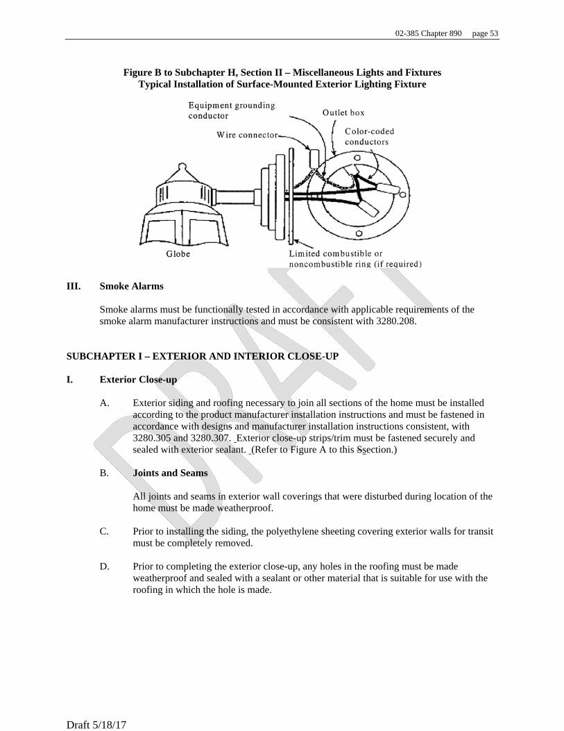
02-385 Chapter 890 page 53
Draft 5/18/17
Figure B to Subchapter H, Section II – Miscellaneous Lights and Fixtures Typical Installation of Surface-Mounted Exterior Lighting Fixture
III. Smoke Alarms Smoke alarms must be functionally tested in accordance with applicable requirements of the
smoke alarm manufacturer instructions and must be consistent with 3280.208. SUBCHAPTER I – EXTERIOR AND INTERIOR CLOSE-UP I. Exterior Close-up A. Exterior siding and roofing necessary to join all sections of the home must be installed
according to the product manufacturer installation instructions and must be fastened in accordance with designs and manufacturer installation instructions consistent, with 3280.305 and 3280.307. Exterior close-up strips/trim must be fastened securely and sealed with exterior sealant. (Refer to Figure A to this Ssection.)
B. Joints and Seams
All joints and seams in exterior wall coverings that were disturbed during location of the home must be made weatherproof.
C. Prior to installing the siding, the polyethylene sheeting covering exterior walls for transit
must be completely removed. D. Prior to completing the exterior close-up, any holes in the roofing must be made
weatherproof and sealed with a sealant or other material that is suitable for use with the roofing in which the hole is made.

02-385 Chapter 890 page 54
Draft 5/18/17
E. Mate-line Gasket
The home manufacturer must provide materials and designs for mate-line gaskets or other methods designed to resist the entry of air, water, water vapor, insects, and rodents at all mate-line locations exposed to the exterior (See Figure B to this Ssection.)
F. Hinged Roofs and Eaves
Hinged roofs and eaves must be completed during installation in compliance with all requirements of the Manufactured Home Construction and Safety StandardsMHCSS (24 CFR part 3280) and the Manufactured Home Procedural and Enforcement RegulationsMHPER(24 CFR part 3282). Unless exempted by the following provisions, -hinged roofs are also subject to a final inspection for compliance with the Manufactured Home Construction and Safety StandardsMHCSS (24 CFR part 3280) by the IPIA or a qualified independent inspector acceptable to the IPIA. Homes with hinged roofs that are exempted from IPIA inspection are instead to be completed and inspected in accordance with the Manufactured Home Installation Program (24 CFR part 3286). This includes homes: 1. That are designed to be located in Wind Zone I; 2. In which the pitch of the hinged roof is less 7:12; and 3. In which fuel burning appliance flue penetrations are not above the hinge.
Figure A to Subchapter I, Section I – Exterior Close-up
Installation of Field-Applied Horizontal Lap Siding
Notes to Figure A: 1. Multi-section homes with horizontal-lap siding can be shipped with no siding on the front and rear end walls. 2. The manufacturer must install doors/windows trimmed with J-rail or the equivalent and protect all exposed materials not designed for exposure with plastic
sheeting for transport. Siding, starter trim, and vents may be shipped loose in the home for installation on set-up. 3. All home installers must ensure that all field installed trim, windows, doors, and other openings are properly sealed according to the siding manufacturer
installation instructions.

02-385 Chapter 890 page 55
Draft 5/18/17
Figure B to Subchapter I, Section I – Exterior Close-up
Note to Figure B: On multi-section manufactured homes, install the sealer gasket on the ceiling, end walls, and floor mate-line prior to joining the sections together.
II. Structural Interconnection of Multi-Section Homes A. For multi-section homes, structural interconnections along the interior and exterior at the
mate-line are necessary to join all sections of the home. B. Structural interconnection must be designed in accordance with the requirements located
in 3280.305 to ensure a completely integrated structure. C. Upon completion of the exterior close-up, no gaps are permitted between the structural
elements being interconnected along the mate-line of multi-section homes. However, prior to completion of the exterior close-up, gaps that do not exceed one inch are permitted between structural elements provided:
1. The gaps are closed before completion of the close-up;
2. The home sections are in contact with each other; and
3. The mate-line gasket is providing a proper seal. All such gaps must be shimmed
with dimensional lumber, and fastener lengths used to make connections between the structural elements must be increased to provide adequate penetration into the receiving member.
III. Interior Close-up A. All shipping blocking, strapping, or bracing must be removed from appliances, windows,
and doors. B. Interior close-up items necessary to join all sections of the home or items subject to
transportation damage may be packaged or shipped with the home for site installation.

02-385 Chapter 890 page 56
Draft 5/18/17
C. Shipped-loose wall paneling, necessary for the joining of all sections of the home must be installed by using polyvinyl acetate (PVA) adhesive on all framing members and fastened with minimum 1 ½ inch long staples or nails at 6 inches on center panel edges and 12 inches on center in the field unless, alternative fastening methods are permitted in the installation instructions (See the Figure to Section III.)
Figure to Subchapter I, Section III – Interior Close-up
Installation of Interior Field-Applied Panels
Note to Figure: Specific designs must be approved by a DAPIA and included in the home manufacturer installation instructions.
IV. Bottom Board Repair
A. The bottom board covering must be inspected for any loosening or areas that might have been damaged or torn during installation or transportation. Any missing insulation is to be replaced prior to closure and repair of the bottom board.
B. Any splits or tears in the bottom board must be resealed with tape or patches in
accordance with methods provided in the manufacturer’s installation instructions.
C. Plumbing P-traps must be checked to be sure they are well-insulated and covered.
D. All edges of repaired areas must be taped or otherwise sealed.

02-385 Chapter 890 page 57
Draft 5/18/17
SUBCHAPTER J – ADDITIONAL REQUIREMENTS I. General A. Exemption Manufactured homes, which are installed in compliance with thisese standards, are
exempt from all state or political subdivision codes, standards or regulations covering the same matters. Other matters are under the authority of the LAHJ.
B. Alterations to the home by a licensed installermechanic are prohibited. C. Installation of Onsite Structures Onsite structures attached to the home shall be installed according to the home
manufacturer’s installation instructions or be designed and approved by a registered engineer or registered architect.
Onsite structures which support their own live load and dead loads and are not attached to
the home are not covered by this standard and come under the authority of the LAHJ. D. The home must be installed and leveled by a licensed installermechanic. E. The home shall be leveled so that all doors and windows operate as intended and
plumbing drains function in a safe and sanitary manner. II. Drainage A. Drainage parts shall be installed only by a licensed installer or a plumber licensed by the
Maine Plumbers’ Examining Board. B. All drainage parts shipped loose with the home shall be installed according to the
manufacturer’s instructions. C. All other drainage shall be installed in compliance with the Maine State Internal
Plumbing Code as adopted by the Maine Plumbers’ Examining Board. D. The main drain line shall be connected to the site’s sewer hook-up using an elastomeric
coupling, acceptable under the Maine State Internal Plumbing Code adopted by the Maine Plumbers’ Examining Board, as shown in the Ffigure to this Ssection:

02-385 Chapter 890 page 58
Draft 5/18/17
Figure to Subchapter J, Section II – Connection to Site Sewer
III. Gas Systems A. Licensed installers are prohibited from performing any gas system work. B. A technician licensed by the Maine Propane and Natural Gas Fuel Board shall: 1. Assemble factory supplied loose shipped gas system parts 2. Convert an appliance from one gas type to another 3. Connect to on-site supply systems and tanks 4. Install propane tank or tanks and system components. C. A technician licensed by the Maine Propane and Natural Gas Fuel Board shall: 1. Inspect all equipment shut-off valves 2. Light pilot lights when provided 3. Adjust burners and spark igniters 4. Inspect all line connections, vent connections and roof jacks 5. Install a natural gas or propane fired appliance in a home
D. All gas system work shall be performed in compliance with NFPA 54, National Fuel Gas
Code, NFPA 58, LP Gas Code and other appropriate rules and codes as adopted by the Maine Fuel Propane and Natural Gas Board.
IV. Fuel Oil Systems A. Licensed installers may install, in compliance with manufacturer’s instructions, loose
shipped fuel oil appliance items.

02-385 Chapter 890 page 59
Draft 5/18/17
B. All other fuel oil system work, not described in the manufacturer’s instructions, including oil supply tanks and fuel oil piping, shall be performed only by a licensed limited tank installer or other technician licensed by the Maine Oil and Solid Fuel Board.
C. All fuel oil system work, not described in the manufacturer’s instructions, shall be done
in compliance with NFPA 31, Installation of Oil Burning Equipment and Chapter 9, Installation of Oil Burning Equipment and other appropriate rules and codes as adopted by the Maine Oil and Solid Fuel Board.
V. Electrical A. Licensed installers may: 1. Install, in compliance with the manufacturer’s instructions, electrical equipment
shipped loose with the home. 2. Connect the main panel to an existing service disconnect. B. All other electrical work, not described in the manufacturer’s instructions, shall be
performed by an electrician licensed by the Electricians’ Examining Board. C. All other electrical work, not described in the manufacturer’s instructions, shall be done
in compliance with NFPA 70, the National Electrical Code.

02-385 Chapter 890 page 60
Draft 5/18/17
APPENDIX A: ROOF LOAD, and WIND AND INSTALLATION ZONES I. Roof Load Zones A. 40 psf Roof Load Zones The following counties are deemed to be within the 40 psf roof load zone: Washington,
Hancock, Aroostook, Somerset, Waldo, Franklin, Penobscot, OxfordKnox and Piscataquis.
B. 30 psf Roof Load Zones The following counties are deemed to be within the 30 psf roof load zone: York,
Cumberland, Kennebec, Sagadahoc, KnoxFranklin, Oxford, Lincoln, and Androscoggin. II. Wind Zones A. Wind Zone I
The following counties are deemed to be within Wind Zone I: Aroostook, Somerset, Waldo, Franklin, Penobscot, Oxford, Piscataquis, York, Cumberland, Kennebec, Sagadahoc, Knox, Lincoln, and Androscoggin.
B. Wind Zone II…100 mph The following counties are deemed to be within Wind Zone II: Hancock and Washington.
III. Installation Zones A. Sites prepared in Washington, Hancock, Aroostook, Somerset, Waldo, Franklin,
Penobscot, Oxford and Piscataquis counties require 24 inches of compacted fill. B. Sites prepared in York, Cumberland, Kennebec, Sagadahoc, Knox, Lincoln, and
Androscoggin counties require 18 inches of compacted fill. STATUTORY AUTHORITY: 10 MRSA §§ 9005-A and 9006 EFFECTIVE DATE: June 22, 2009 – filing 2009-256 AMENDED: November 10, 2012 – Summary, Subchapter A Section VII, filing 2012-310