Embed Size (px)
Citation preview

1Introduction
Industrial cabling technologyfor Industrial Ethernet/PROFINET and PROFIBUS
Brochure • November 2008
SIMATIC NET

2 Introduction
Introductionnetworks – the backbone of industrial communication
Powerful, open and rugged bus systems that ensure efficient communication in automation solutions, regardless of whether they are intended for data communication, or for process or field communication: Networks must be the reliable medium of data trans-mission in industrial communication. Openness and flexibility of the individual bus systems in different topologies enable systems and their expan-sions to be linked. By using standardized bus systems, it is possible to connect standardized components from different suppliers without any problems. This provides maximum protection of investment, as existing net-works can be extended without any adverse effects.Siemens provides all of the components for an integra- ted overall solution beyond the network's limits. This not only includes active network components but also industry-standard connection systems.
According to the standards ISO/IEC 11801 and EN 50173 for structured building cabling, corresponding standards were created:
• ISO/IEC 24702 for structured cabling of industrial buildings
• IEC 61918 for specific cabling in industrial plants
Use of the communication systems
Ind
ust
ria
l E
the
rne
t
PRO
FIN
ET
PRO
FIB
US
DP
Enterprise Resource Planning (ERP)(e.g. PC)
n -
Control(e.g. SIMATIC S7-300) n n n
Motion Control(e.g. SIMOTION) - n n
Intelligent field devices(e.g. ET 200S/CPU) n n
Simple field devices (e.g. ET 200) n n
Sensors/actuators n n
Drives(e.g. SINAMICS) - n n
SIRIUSmotor starters n n
SINUMERIK - n n
Safety-orientedcommunication n n
not suitable - suitable n ideally suitable

3Introduction
Components for the network
Both passive network components (e.g. cables, connec-tors, bus terminals) and active network components (e.g. switches) are used in constructing an electrical or optical network. Network cabling in the industrial sec-tor is a significantly greater challenge than in the office world. Cables for data and energy
Data linesUnlike cables in the office, industrial cables must be able to withstand an aggressive environment and high tempera-tures or have excellent resistance to lateral force. This is achieved by means of the special cable construction (star quad). The cables are silicon-free, which also makes them suitable for use in paintshops. Thanks to the low bending radius they withstand the high tensile loads that occur par-ticularly when the cables are pulled into cable ducts. The capacity to bear mechanical and chemical loads is an important criterion for industrial cables. The shielded cable construction permits secure data trans-mission even in industrial areas subject to electromagnetic interference.
Power linesVarious rugged power cables are available for the con-struction of PROFINET/PROFIBUS networks. They are also silicon-free and can therefore also be used in paintshops. The cable jacket is resistant to mineral oil and grease and protects the power line in harsh industrial environments.
Contents
Introduction 2
Networks – The backbone of industrial communication .................................................. 2Components for the network .............................. 3Passive and active components in the network ..... 4A fault-free connection on-site in 60 seconds with FastConnect .............................................. 6FastConnect for Industrial Ethernet .................... 7FastConnect for PROFIBUS ................................... 8
Industrial Ethernet 9
Network selection criteria .................................... 9Electrical Industrial Ethernet network ................. 10Overview of electrical Industrial Ethernet cables . 11Plug-in connector for Industrial Ethernet ............ . 12Patch technology for Industrial Ethernet ............. 14Electrical Industrial Ethernet networkWhich connector fits which cable? ..................... 16Optical Industrial Ethernet networkOverview of optical cables ................................. 17Optical Industrial Ethernet networkWhich connector fits which cable? ..................... 20
PROFIBUS 21
Network selection criteria .................................. 21Electrical PROFIBUS network .............................. 23Electrical PROFIBUS network Overview of PROFIBUS bus cables ...................... 24Optical PROFIBUS networkOverview of optical cables ................................. 26Optical PROFIBUS network Overview of optical PROFIBUS bus cables ............ 28Connection components for PROFIBUS ............... 29Electrical and optical PROFIBUS network Which connector fits which cable? ..................... 30

Passive and active components in the network
The active network components connect individual net-work segments to form a network structure. On removal or failure of a network component, the topology is forced to divide into separate partial segments. As a consequence, communication between the nodes in the two different sub-networks is no longer possible.
Ring topology
The ring topology is created by connecting the two ends of the lines of an active linear topology into a physical ring. A special redundancy mechanism ensures that the ring structure remains a logical line in normal circumstances and therefore prevents any message frames from circu- lating. On failure of a ring section or by means of active network components, the mechanism ensures that an alternative route is quickly available in the ring. The net-work does not break up into two segments. The effects of a network component fault are therefore confined to the failed component and any terminal equipment connected to it. If a ring section is interrupted, e.g. due to a broken cable, communication continues to function without any disturbance. The reconfiguration time in this case is less than in the office environment and thus meets the demands of the automation world.
4 Introduction
Star topology
The star topology uses a central hub (switch). The indi-vidual nodes in the network are connected to the active network components via individual point-to-point connec-tions.The tree structure is created by the hierarchical arrange-ment in series of several star structures to form a single network.
In practice, depending on the requirements for the individ-ual transmission routes, it may be a matter of combining fiber-optic cables and twisted-pair cables. Typical applica-tion examples include the Ethernet office networking or the networking of production cells in a production plant using Industrial Ethernet. In comparison with the ring or linear structure, the amount of cabling is considerably greater due to the long paths back to the star point.
Industrial Ethernet/PROFINET connection options for any application (ring and star topology)
Communication or sub-network failures can be prevented by configuring ring or star topologies. These structures can be implemented with the aid of the SCALANCE X family of products.
Switching cabinetSwitching cabinet
SIMATIC S7-300 with CP 343-1
SIMATIC TP277B
FC FO Standard Cable GP
IE FC RJ45 Modular Outlet
Switch SCALANCE
X204-2
IE TP Cord

5Introduction
Linear topology
In a linear network topology, the network component typically only has one or just a few connection points for network stations.Furthermore, linear structures can also be constructed using devices with two integrated network interfaces.
Connection for Fast and Gigabit Ethernet (linear topology)
Switching cabinet
IE FC RJ45 Modular Outlet Insert 1GE
IE FC RJ45 Modular Outlet Insert 1GE
IE FC RJ45 Modular Outlet Insert 2FE
IE FC RJ45 Modular Outlet Insert 2FE
S7-300
ET 200S
IE TP Cord 4x2
IE TP Cord 2x2
PC

A fault-free connection on-site in 60 seconds
with FastConnect
Problems often occur on-site when laying the cabling for industrial plants: When stripping the cable, assembling the plug-in connector, or if cables are connected incorrectly.
If you want:• perfectly matched components• the installation of industry-standard network structures
within the shortest possible time without specialist knowledge
• minimal time spent connecting terminals• to avoid installation errors• even easy assembly on-site• and the resulting reduced overall costs during the
lifespan of the system then the quick-assembly system FastConnect from SIMATIC NET is the right system for you. It consists of a cable, connector and tool and can be used for Industrial Ethernet/PROFINET and PROFIBUS.
6 Introduction
With optimally matched components, SIMATIC NET cables enable the installation of high-performance indus-trial network structures.
• Minimal installation time• Easy stripping of outer sheath and braided shield in one
step• Simple connection method for Industrial Ethernet
FastConnect cables• Easy assembly thanks to preset FastConnect stripping
tool• Reliable shield contacting and strain relief• M12 and RJ45 connection method for Industrial Ether-
net/PROFINET and PROFIBUS
The advantages add up with FastConnect
With the FastConnect (FC) system for Industrial Ethernet, structured cabling from the office environ-ment becomes industry-standard for installation in production halls:
7 An integrated system of FC plug-in connectors and an extensive range of FC cables with appropriate UL approvals for Industrial Ethernet/PROFINET and PROFIBUS
7 Error avoidance through the use of color coding, preset tools, and clearly specified materials
7 Dependable screen contacts and strain relief as well as good EMC shielding for copper cabling
7 The use of standard-compliant connection technology for Industrial Ethernet/PROFINET and PROFIBUS

7Introduction
FastConnect for Industrial Ethernet
Industrial Ethernet/PROFINET
Fast connection of:• RJ45 plug-in connectors
2 x 2 and 4 x 2applying the insulation displacement method – using a stripping tool – to stripped 4 and 8-core IE FC bus cables
• M12 plug-in connectorsby means of – stripping tool – to stripped 4-core IE FC bus cables
Stripping
Assembly with RJ45 plug-in connector
Assembly with M12 plug-in connector

FastConnect for PROFIBUS
8 Introduction
PROFIBUS
Fast connection of:• Bus connector
by means of insulation displacement method – using stripping tool – to bared PB FC bus cables
• M12 plug– using stripping tool – to bared PB FC bus cables
PROFIBUS PA (hazardous area)
Fast setup of:• Fieldbus segments
According to IEC 61158-2; terminals can be connec- ted with FC process cable or SpliTConnect M12 out-let/M12 jack
Stripping and assembly with M12 plug-in connector
SpliTConnect
Stripping and assembly by means of insulation displacement

The type of network (elec-trical or optical, copper or fiber-optic cables) is deter-mined by the environmen-tal conditions in which it is to be constructed.
9Introduction
Twisted pair network Fiber-optic network
Flexibility of the network topology
n n n n n n n n
Suitability for high transmission rates
n n n , 1) n n n n 1)
Inter-building networking , , , , n n n n
EMC n n n , n n n n
Simple cable laying n n n , n n n ,
Range of cables for special applications
Cables for indoors;trailing cables; ship wiring cables;FastConnect cables
Cables for indoors and outdoors; trailing cables; halogen-free cables
Effect of voltage failure Failure of a subnetwork 2) Failure of a subnetwork 2)
Effect of path failure Network splits into two separatelyfunctioning subnetworks 3)
Network splits into two separatelyfunctioning subnetworks 3)
Max. network expansion 5000 m 4) Up to 150 km: over 150 km, consider signal propagation delay
Max. distance between two network nodes/access points
100 m 50 m POF100 m PCF3000 m multi-mode70000 m single mode
Max. length of connecting cable 100 m 50 m POF100 m PCF3000 m multi-mode70000 m single mode
Pre-assembled cables Yes Yes
Assembly on site without special tool;FastConnect technology
with special tool
Integrated diagnostics support LED indicators; signaling contact;SNMP network management;Web-based management,PROFINET diagnostics
LED indicators; signaling contact;SNMP network management;Web-based management,PROFINET diagnostics
Redundant network structures Electrical ring or doubling of the infrastructure (linear, star, tree)
Optical ring or doubling of the infra-structure (linear, star, tree)
1) Suitable for 10 Mbit/s, 100 Mbit/s and 1000 Mbit/s
2) Safeguard against subnetwork failure by means of redundant power supply
3) No effect with ring structure4) With 50 switches in the ring
n n n n suitablen n n , partially suitablen n , ,
n , , ,
, , , , not applicable
Industrial Ethernetnetwork selection criteria

Electrical Industrial Ethernet network
Installation cables
Various cable designs are available for the construction of structured Industrial Ethernet cabling in the harsh indus-trial environment.The UL and Cat5 Plus-certified 4 and 8-core FastConnect cables are available as:
• Standard cable for universal applications• Trailing cable for moving machine parts• Cable approved for laying in ships and offshore units• Flexible cable for occasional movement• Torsion-resistant cable for robotic applications
(TP torsion cable)
IE FC stripping tool
The Industrial Ethernet FC stripping tool saves time when stripping the FC cables.Due to the accurately preset cutting depths and spacing of the blades it is possible to remove the outer sheath and the braided shield of the FC cables to the precise measurement in a single operation. This rules out possible faults due to inaccurate stripping of the cable for assembly in the vari-ous components.
The 4 and 8-core FastConnect (FC) Industrial Ethernet cables have a radially symmetric design, which allows the use of a stripping tool FC stripping tool.This allows plug-in connectors and patch outlets to be quickly and easily connected on-site.
IE FC TP cable 2 x 2• The double shield makes it especially suitable for routing
through industrial areas with strong electro-magnetic fields
• Simple connection without special tools to the insulation displacement contacts of the FC plugs
• Integrated grounding concept can be achieved via the outer shielding of the bus cable
• Printed meter marks• Versatile application due to special bus cables• Network is immune to interference thanks to double-
shielded cables • Silicone-free and therefore suitable for use in the auto-
motive industry (e.g. in paint shops)
10 Industrial Ethernet
IE FC TP cable 4 x 2 • 8-core FastConnect installation cable for cabling system
with Gigabit capability• User-friendly stripping technique with IE FC stripping
tool• Simple connection to IE FC RJ45 modular outlet by
means of insulation displacement technology• Time is saved thanks to easy and quick installation• Due to the 8-core cabling, it is possible today to imple-
ment 2 Fast Ethernet connections, but it will also be possible to upgrade to a Gigabit Ethernet connection in future
• Noise-immune network due to a consistent grounding concept
Possibilities of device networking with patch cables and outlets
When using the outlets in the control cabinet or in a con-trol room, pre-assembled RJ45 patch cables are available in different versions (TP cord 4x2, TP cord 2x2 RJ45/sub D) for connecting network components or terminals
For flexibly connecting devices with different data rates, there is the Industrial Ethernet FC outlet RJ45 (10/100 Mbit/s) to 4-core Industrial Ethernet FC cables, or the Industrial Ethernet FC modular outlet (10/100/1000 Mbit/s) to 8-core Industrial Ethernet FC cables for connecting to terminals or data and power supply of remote stations (e.g. Access Point SCALANCE W).
Industrial Ethernet FC TP standard cable
single core sheath braided shield
outer sheathfoil shield
copper core
inner sheath
G_I
K10
_XX
_100
33

11Industrial Ethernet
The following cables are offered for the various topologies, requirements or application areas:
Overview of electrical Industrial Ethernet cables
Cable type Designation Characteristics Area of application
Twisted pair TP cord Patch cables, with RJ45, 15 or 9-pin sub D con-nectors, pre-assembled
For connection of stations to network components within a control cabinet, up to 10 m cable length
FastConnect
IE FC TP cable 2 x 2, 4-core for Fast Ethernet networks
IE FC TP cable 4 x 2, 8-core for Gigabit Ethernet networks
IE FC TP standard cable GP 2x2
IE FC TP flexible cable GP 2x2
IE FC TP FRNC cable GP 2 x 2
IE FC TP trailing cable GP/IE FC TP trailing cable 2x2
IE FC festoon cable GP 2 x 2
IE FC TP food cable 2 x 2
IE FC TP marine cable 2x2
IE TP torsion cable 2x2
IE FC TP standard cable 4x2 (AWG 22)
IE FC TP cable 4x2 (AWG 24)
Installation cables, in-sulation displacement technology, sold by the meter
For direct connection between network station and component, used for structured cabling, fast and easy connection of cables to the FC contacts
- Standard bus cable with rigid cores and specialdesign for quick assembly; 4 rigid cores form a star quad
- Flexible bus cable for the special application of occasional motion control; four cores (stranded) form a star quad
- Flexible, halogen-free cable for use in buildings (FRNC= Flame Retardant Non Corrosive); 4 cores (stranded) form a star quad for occasional movement
- Highly flexible bus cable for the special application of constant motion control in a tow chain, e.g. for continuously moving machine parts; 4 cores (stranded) form a star quad
- Flexible cable for special continuous motion applications in a trailing cable/festoon, e.g. in crane systems; 4 cores (stranded) form a star quad
- Flexible cable for special applications in the food, beverages and tobacco industries; 4 cores (strand-ed) form a star quad
- Bus cable for special marine applications; 4 cores (stranded) form a star quad, halogen-free, certified for marine applications
- Highly flexible bus cable for the special application of continuous motion control, e.g. for use with robots; stranded core
- For setting up Industrial Ethernet networks up to 100 m in combination with the IE FC modular outlet and the TP cords
- For direct connection up to 60 m without patch technology with IE FC RJ45 plug 4x2 and IE FC TP cable 4x2 (AWG24)
Connecting cableM12-180/M12-180
Pre-assembled with two 4-pin M12 connectors (IP65)
- 4-core connecting cable for IP65/IP67 components
Hybrid IE hybrid cable Hybrid cable for simul-taneous transmission of data (10/100 Mbit/s) and energy (24 V/400 mA); insulation displacement technology, sold by the meter
Industrial and office sector; for IE FC RJ45 modular outlet and access point SCALANCE W with hybrid connector
Power Energy cable Power line,sold by the meter
For connection of signaling contact or 24 V DC power supply

Plug-in connector for Industrial Ethernet
IE FC RJ45 plug 90/145/180
The compact and rugged design of the plug-in connectors permits their use in the industrial environment and on all devices from the office world.The Industrial Ethernet FastConnect RJ45 plugs allow easy and fast assembly of the 4-core Industrial Ethernet FC twisted pair installation cables in the field (PROFINET-com-patible).They are available for • 90°• 145° and• 180° cable outletsThe rugged, industry-standard metal enclosure provides optimum protection against interference for data commu-nication.The integrated 4 insulation displacement contacts make the contacting of the FC cable versions easy and prevent faults.As the plug-in connector has no small parts that can be lost, assembly is also possible under difficult conditions.The FC RJ45 plugs allow point-to-point connections (100 Mbit/s) to be implemented for Industrial Ethernet between two terminals/network components up to 100 m without patch cables.By latching the connector to the device casing (e.g. with SCALANCE X, CSM 377, SCALANCE S, S7-300 CPUs, CPs, or ET 200S), the plug-in connection is relieved of tension and bending strain.
12 Industrial Ethernet
Perfect assembly of a cable with FastConnect takes less than 60 sec-
onds
SCALANCE X multi-port switch with RJ45 connection technology
Industrial Ethernet FC RJ45 plug
• Degree of protection IP20• Easy on-site assembly for implementing
direct device connections up to 100 m with IE installation cables, 4 and 8-core without patch systems
Insert the cores according to the color-coding as far as the end stop
and press down on the contact lid
CP 443-1 Advanced with RJ45 connection technology

Industrial Ethernet FC M12 plug PRO
• IP65/67 degree of protection• Easy assembly on-site for application-specific M12 plug-
in cables by means of FastConnect M12 plug-in connec-tors that can be assembled in the field (IE FC M12 plug PRO, D-coded)
13Industrial Ethernet
Industrial Ethernet push-pull plug PRO
• IP65/67 degree of protection• Data plug-in connector that can be assembled in the
field for IE FC TP and POF/PCF cables for transmitting data up to 100 Mbit/s
• PROFINET-compatible• Power plug-in connector suitable for on-site assembly
for transmitting 2x24 V between Industrial Ethernet stations
• The plug-in connectors make contact with the device using a push-pull mechanism.
ET 200eco with M12 connection technology
SCALANCE X with push-pull connection technology
SCALANCE X208 with M12 connection technology
ET 200pro with M12 connection technology
Plug-in connector for Industrial Ethernet

Patch technology for Industrial Ethernet
IE FC outlet RJ45
The FC outlet RJ45 is used for the transition from Industrial Ethernet FC cables to pre-assembled TP cords by means of a RJ45 socket.It provides the following benefits:
• Rugged metal enclosure• Insulation displacement contacts for fastest connection
to Industrial Ethernet FC cables• By arranging several FC outlets RJ45 in a row, it is
possible to construct a patch panel with any density of connections (e.g. 16 outlets on 19" width is possible)
• DIN rail mounting and direct screw connection is possible
For time-saving and trouble-free connection of network components or terminal equipment, various RJ45 patch cables are available.
IE FC RJ45 modular outlet
Due to the continuous rise in transmission rates for Ethernet (10/100/1000 Mbit/s) and the service-neutral cabling from the office sector, an 8-core cabling system is also implemented by SIMATIC NET.The Gigabit cabling system facilitates the transition from the 4-core Industrial Ethernet FastConnect cabling system to the 8-core, Gigabit cabling system.The FC modular outlet can optionally be equipped with a replaceable insert with:• 2x RJ45 sockets for 100 Mbit/s systems• 1x RJ45 socket for 1000 Mbit/s systems• 1x 24 V, 1x RJ45 socket for 100 Mbit/s systems In this way it is possible not only to implement individual device connections, but also 100 Mbit/s double connec-tions.Just like the 4-core cabling system, this system also takes into account the conditions in the field of industrial auto-mation. Assembly is particularly easy, as no special tools are necessary (e.g. same FC stripping tool as for the 4-core cabling system).
14 Industrial Ethernet
Cabling example with IE FC RJ45 modular outlet
Cabling example with IE FC outlet RJ45

15Industrial Ethernet
Industrial Ethernet FC outlet RJ45
7 Simple connection method for 4-core installationcables
7 10/100 Mbit/s transfer rates7 Degree of protection IP207 Transition from rugged Industrial Ethernet FC
cables (2 x 2) to pre-assembled TP cords7 Integrated insulation displacement contacts and
RJ45 socket7 Patch fields are implemented with several RJ45 FC
outlets
Industrial Ethernet FC RJ45 modular outlet
7 Simple connection method for 8-core installation cables
7 10/100/1000 Mbit/s transfer rates7 Can be mounted inside or outside of control
cabinets due to IP40 degree of protection7 Without swapping the cabling, it is possible to
upgrade from 100 to 1000 Mbit/s with a replaceable insert
7 Basis for implementing structured cabling according to ISO/IEC 24702
Patch technology for Industrial Ethernet

Electrical Industrial Ethernet network
Which connector fits which cable?
16 Industrial Ethernet

17Industrial Ethernet
Optical Industrial Ethernet network
Overview of optical cables
Fiber-optic cables
The fiber-optic cable (FOC) is used for the transmission of signals with the aid of electromagnetic waves within the range of optical frequencies.The light beam is guided by total reflection at the transi-tion from the core to the fiber cladding, which has a lower refractive index than the core.The fiber-optic cable is provided with a coating. The term “fiber” is often also used for fiber-optic cables.
Glass FOC with SC connector
PCF FOC with SC RJ connector
7 Optical signal transmission7 Tap-proof, as fiber-optic cables do not emit radiation7 Unaffected by external noise fields7 No grounding problems7 Electrical isolation7 Low weight7 Simple cable laying due to rugged cable structure
For Industrial Ethernet, fiber-optic cables are offered with fibers made of glass, PCF or POF:
• Glass FOC:Duplex cable for fiber-optic networks both indoors and outdoors and for use on ships or offshore installations for medium to long distances (3 km with multi-mode and up to 26 km with single mode)
• PCF-FOC:Duplex cable for PCF networks both indoors and out-doors for smaller automation networks (50 m with POF, 100 m with PCF) with simple on-site assembly
• POF-FOC:Duplex cable for POF networks indoors for smaller auto-mation networks (50 m with POF, 100 m with PCF) with simple on-site assembly

18 Industrial Ethernet
Optical Industrial Ethernet network
Overview of optical cables
Glass fiber-optic cables
• Used for the optical Industrial Ethernet and PROFIBUS network
• Rugged construction for industrial applications both indoors and outdoors
• Halogen-free design for use in buildings• Trailing cable for special applications with forced motion
control• High interference immunity, as they are not sensitive to
electromagnetic interference• Available pre-assembled
Plastic/PCF fiber-optic cable
SIMATIC NET plastic and PCF fiber-optic cables are used for the construction of optical PROFINET and Industrial Ethernet networks indoors. Devices with integral optical interface (SC RJ connection system) are, for example, SCALANCE X200-4P IRT, SCALANCE X201-3P IRT, SCALANCE X202-2P IRT, SCALANCE X101-1POF, ET 200S.Plastic and PCF-FOCs are easy to assemble on site using SC RJ connectors. The maximum cable length between two devices is 50 m for POF and 100 m for PCF fiber-optic cables. PCF cables are also available pre-assembled with 2 SC RJ plugs.
PCF fiber-optic cables
• Duplex cable for PCF networks in indoor and outdoor applications
• Electrical isolation of PROFINET/Ethernet devices• Protection of the transmission route against electromag-
netic interference• Cable lengths up to 100 m possible• Rugged standard cables, designed for industrial use
POF fiber-optic cables
• Duplex cable for POF networks in indoor and outdoor applications
• Electrical isolation of PROFINET/Ethernet devices• Protection of the transmission route against electromag-
netic interference• Cable lengths up to 50 m possible• Rugged standard cables, designed for industrial use
Glass fiber-optic standard cable
PCF fiber-optic trailing cable
POF fiber-optic standard cable
Optical fiber
Strain relief usingaramide yarn
Outer sheathSingle core
sheathHollow core
G_I
K10
_XX
_100
30
PCF fiber
Fleece wrapping with strain relief elements
Hollow core
Strain relief usingaramide yarn
Outer sheath
Single core sheath
Support element
G_I
K10
_XX
_100
31
POF fiber Single core sheath
Outer sheathStrain relief usingaramide yarn
G_I
K10
_XX
_101
79

19Industrial Ethernet
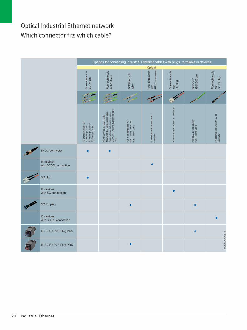
This overview shows which Industrial Ethernetconnector can be assembled with which cable.
Optical Industrial Ethernet network
Overview of optical cables
Cable type Designation Characteristics Area of application
FastConnect
FO standard cable GP (50/125) FO ground cable (50/125)
FO trailing cable GP (50/125)FO trailing cable (50/125)SIENOPYR marine duplexfiber-optic cable (62.5/125)
Glass fiber, sold by the meter or pre-assembled with 4 BFOC or SC con-nectors
Laying in indoor and outdoor areas
Cable versions:- Rugged standard cable for uni-
versal applications - Watertight cable in lateral and
longitudinal direction for use outdoors; with non-metallic rodent protection; laying in the ground is possible
- Cable for use in tow chains - Halogen-free, tread-resistant,
flame-retardant cable with marine approval for laying in ships and offshore installa-tions
Fiber-opticPlastic
POF standard cable GP 980/1000
POF trailing cable 980/1000
PCF standard cable GP 200/230
PCF trailing cable 200/230
PCF trailing cable GP 200/230
Plastic fiber-optic cable, sold by the meter orpre-assembled (PCF-FOC) with 4 SC RJ connectors
Laying in indoor and outdoor areas
Cable versions:- POF-FOC standard cable for
permanent cabling indoors up to 50 m with PVC sheath
- POF-FOC trailing cable for moving applications (e.g. trail-ing cable) up to 50 m with rugged PUR sheath
- POF-FOC standard cable for permanent cabling indoors and outdoors up to 100 m with rugged PVC sheath
- POF-FOC trailing cable for high mechanical loads indoors and outdoors up to 100 m with rugged PUR sheath
- POF-FOC trailing cable for lower mechanical loads in-doors and outdoors up to 100 m with PVC sheath
20 Industrial Ethernet
Optical Industrial Ethernet network
Which connector fits which cable?

21PROFIBUS
PROFIBUSnetwork selection criteria
The type of network (elec-trical or optical, copper or fiber-optic cables) is deter-mined by the environmen-tal conditions in which it is to be constructed.
Criteria Electrical network Optical network
RS 485 according to IEC 61158/61784
IEC 61158-2(PA)
Plastic PCF Glass
EMC n n n , 1) n n n , n n n n n n n n n n n n
Inter-building network-ing
n n , , 1) n n , , n n n n n n n , 5) n n n n
Range n n , , 2) n n , , n n n n n n , , n n n n
Suitability for high transmission rates
n n n , 4) — n n n , n n n n n n n n
Simple connector assembly
n n n n n n n n n n n , n n , , 3) n , , , 3)
Simple cable laying n n n , n n n , n n , , n n , , n n , ,
Equipotential bonding measures required
Yes Yes No No No
Cables for special applications
n n n n n , , , n , , , n , , , n n , ,
Use with moving stations
n n , , — , , , , , , , , n n , ,
Use in intrinsically safe environment
— n n n n — — —
1) Lightning protection measures required
2) Depending on the transmission rate
3) Trained personnel and special tool required
4) Careful laying required5) Outer conductor required
(on request)
n n n n suitablen n n , partially suitablen n , ,
n , , ,
, , , ,
— not applicable
G_I
K10
_XX
_500
10

Network selection criteria
22 PROFIBUS
1) Plastic optical fiber is also referred to as polymer optical fiber (POF)
2) Depending on type of cable used3) Depending on data rate used and performance4) Integrated interfaces (ET 200M, ET 200X)5) for PROFIBUS PA 1.9 km
Electr. network segmentsconnectable
Integrated interfaces
Bus terminal
Bus connector
Connection ofnodes via
Transmission protocols
Criteria
all all DP
up to 1 km 3) up to 15 km 2) up to 300 m 2)
9.6 km 5) 90 km 9.6 km
Electrical PROFIBUS with OLM with integr. interface/OBT
Electrical network Optical network
Transition media
Distances
Topology
Plastic 1)
PCF
Glass
Shielded two-core cable
max. network size
between two nodes
Bus
Line
Tree
Ring
suitable
Irrelevant to this application
OLM
4)
G_I
K10
_XX
_501
33

There are different networking options for PROFIBUS net-works, depending on the respective application: • Electrical data transmission by means of shielded
twisted-pair cables with circular cross-section available as standard type, with PE or PUR sheath, halogen-free design, cables for use underground, in tow chains or specially for hazardous areas. With the PROFIBUS FastConnect system, the PROFIBUS copper cables can be quickly and easily assembled on-site.
• Optical data transmission via fiber-optic cable with glass or plastic fibers for indoor or outdoor applications, as trailing cable or as halogen-free version.
23PROFIBUS
Electrical PROFIBUS network
PROFIBUS bus cables
The design of the FastConnect (FC) bus cables is radially symmetric and allows the use of a stripping tool. This means that the bus connectors can be assembled quickly and easily.
PROFIBUS FC standard cable
PB FC plug 180
7 A wide variety of possible applications thanks to special bus cables (e.g. underground cable, trailing cable, use in hazardous areas)
7 Network is immune to interference thanks to double shielded cables and a uniform grounding concept
7 Time saving due to simple and fast connector assembly with FastConnect cables
7 Silicon-free, therefore particularly suitable for use in the automotive industry (e.g. on paint shop conveyors)
7 Flame-retardant bus cable (halogen-free) 7 Easy length measurement thanks to printed meter
Single core sheath Braided shield
Outer sheathFoil shield
Copper core
Inner sheath

24 PROFIBUS
The following applies for all PROFIBUS bus cables:
• Due to the double shielding, they are particularly suit-able for laying in industrial environments subject to electromagnetic interference.
Electrical PROFIBUS network
Overview of PROFIBUS bus cables
Cable type Designation Characteristics Area of application
For the construction of PROFIBUS networks, the following different types of silicon-free cables are offered for the different applications:
Bus cables with FastConnecttechnology
PROFIBUSFC standard cable GPFC robust cable FC food cable
FC ground cable
FC flexible cable FC trailing cable
FC FRNC cable GP FC process cable GP
Quick and easy connec-tor assembly with the aid of the stripping tool. Shielded and twisted 2-core cables constructed with radial symmetry.
- Standard cable for universal applications
- Special cable for chemically and mechanically demanding environments
- Special cable for the food, beverages and tobacco indus-tries
- Special cable for routing under-ground
- Special cable for use in tow chains
- Trailing cable for moving ma-chine parts (stranded wire)
- Halogen-free and flame-retar-dant cable
- Bus cable for fieldbus systems compliant with IEC 61158-2 (hazardous and non-hazardous
Bus cables withoutFastConnecttechnology
PROFIBUSFestoon cable GPTorsion cable ECOFAST hybrid cable GP SIENOPYR marine cable
Shielded, twisted-pair cable with circular cross-section; sold by the meter
- Special cable for festoon sus-pension
- Special cable for use on machine parts where the cable is subject to torsion (stranded)
- Hybrid cable for data trans- mission and voltage supply to ECOFAST stations (stranded)
- Halogen-free, tread-resistant, flame-retardant cable with marine approval for permanent laying in ships and offshore installations
• A consistent grounding concept can be implemented via the outer sheath and the ground terminals of the bus terminal.
• The printed meter marks simplify assembly.

25PROFIBUS
Cable type Designation Characteristics Area of application
Plug-incables
PROFIBUSConnecting cable 830-1T
PROFIBUSConnecting cable 830-2
PROFIBUSM12 connecting cable
7/8" connecting cable
Twisted-pair conduc-tors (cores of stranded copper) with a braided shield and a 9-pin sub D connector at both ends. Both ends of the cable are terminated with a resistor combination (cannot be switched off).
PROFIBUS standard bus cable with two 9-pin connectors (90° angled), pre-assembled. One connector of the pre-assembled connecting cable is equipped with a programming device interface.
Pre-assembled connect-ing cable (PROFIBUS FC trailing cable) with two 5-pin M12 plugs/sockets
Pre-assembled connect-ing cable with two 5-pin 7/8" plugs/sockets
Via the PROFIBUS 830-1T connecting cable, the connection between an electrical PROFIBUS interface and a PROFIBUS station (OLM, OBT and end station) can be established with up to 12 Mbit/s.
The connecting cable 830-2 is used for connecting PROFIBUS stations (e.g. HMI) to PLCs at transmission rates of up to 12 Mbit/s.
The PROFIBUS M12 connecting cable is used to connect PROFIBUS nodes (e.g. SIMATIC ET 200) with degree of protection IP65
The 7/8" connecting cable is used for supplying power to PROFIBUS stations (e.g. SIMATIC ET 200) with degree of protection IP65
Hybrid
PROFIBUS hybrid standardcable GP
Hybrid cable with two energy cores (1.5 mm²), sold by the meter
The hybrid cable is used for supplying data and energy to the ET 200pro
Cable versions:- Standard cable for universal
applications- rugged, trailing-type and weld
spatter-proof hybrid cable, e.g. for use in welding cells

26 PROFIBUS
Optical PROFIBUS network
Overview of optical cables
Fiber-optic cable (FOC)
The fiber-optic cable (FOC) is used for the transmission of signals with the aid of electromagnetic waves within the range of optical frequencies.The light beam is guided by total reflection at the transi-tion from core to fiber cladding, which has a lower refrac-tive index than the core.The fiber-optic cable is provided with a coating. The term “fiber” is often also used for fiber-optic cables.
Advantages• Optical signal transmission• Tap-proof, as fiber-optic cables do not emit radiation• Unaffected by external noise fields• No grounding problems• Electrical isolation• Low weight• Easy to lay For PROFIBUS, fiber-optic cables with glass and plastic fibers are offered for indoor and outdoor applications as well as for use on ships and offshore installations:
Glass fiber-optic cables• Used for the optical Industrial Ethernet and PROFIBUS
network• Rugged construction for industrial applications both
indoors and outdoors• Halogen-free design for use in buildings• Trailing cable for special applications with forced motion
control• High interference immunity, as they are not sensitive to
electromagnetic interference• Available pre-assembled
Glass fiber-optic standard cable
POF fiber-optic trailing cable
PCF fiber-optic trailing cable
PCF fiber
Fleece wrapping with strain relief elements
Hollow core
Strain relief usingaramide yarn
Outer sheath
Single core sheath
Support element
G_I
K10
_XX
_100
31
POF fiber
Fleece wrapping with strain relief elements
Strain relief usingaramide yarn Outer sheath
Single core sheath
Optical fiber
Strain relief usingaramide yarn
Outer sheathSingle core
sheathHollow core
G_I
K10
_XX
_100
30

27PROFIBUS
Plastic/PCF fiber-optic cable
SIMATIC NET plastic and PCF fiber-optic cables are used for the construction of optical PROFIBUS networks or for opti-cal linking of segments using RS485 technology in indoor and outdoor applications. They can be assembled on site using 2x2 simplex or 2x2 BFOC connectors. The maximum cable length between two DP devices is 300 m. Longer cable lengths up to 400 m can be implemented with PCF-FOC.
POF fiber-optic cables• Electrical isolation of PROFIBUS devices and PROFIBUS
segments• Protection of the transmission route against electromag-
netic interference• Cable lengths up to 80 m using plastic fiber-optic cables • Rugged standard fiber-optic cables, designed for indus-
trial use
PCF fiber-optic cables• Electrical isolation of PROFIBUS devices and PROFIBUS
segments• Protection of the transmission route against electromag-
netic interference• Up to 400 m using PCF fiber-optic cables• Rugged standard fiber-optic cables, designed for indus-
trial use
SIMATIC NET PCF fiber-optic cables are used to construct optical indoor and outdoor PROFIBUS DP networks. Their special construction facilitates connector assembly on site. PCF fiber-optic cables can readily be assembled on site using 2 x 2 simplex connectors or 2 x 2 BFOC connec-tors (bayonet fiber-optic connectors). The maximum cable length between two DP devices is 300 m and between two OLMs 400 m. Two assembly cases are offered for this: • Assembly case for BFOC connectors • Assembly case for simplex connectors
PROFIBUS DP devices with integrated optical interface (sim-plex connection technology) are e.g. OBT, CP 342-5 FO,CP 5613 FO, IM 153-2 FO, IM 467 FO.
Assembly made easy
PCF fiber-optic cables are easily assembled on site with 2 x 2 simplex connectors or 2 x 2 BFOC connectors using the PCF fiber-optic cable termination kit.Two versions of the assembly case are available for PCF fiber-optic cables:• Assembly case for HP simplex connectors;
for local assembly of HP simplex connectors; comprising a stripping tool, buffer stripping tool, Kevlar cutters, crimping tool, fiber breaking tool and microscope
• Assembly case for BFOC connectors;for local assembly of BFOC connectors; comprising a stripping tool, buffer stripping tool, Kevlar cutters, fiber breaking tool, and microscope.
The termination kits provide the following benefits• Simple installation of the unassembled cable in industrial
plants• Flexible connector assembly on PCF FOCs possible on site
(HP simplex, BFOC connector)• Prevention of faults by simply checking the assembled
connectors on site using a microscope• Simple repair of PCF FOC in the field by laying new
PCF cable
BFOC connectorSimplex connector

28 PROFIBUS
Optical PROFIBUS network
Overview of optical PROFIBUS bus cables
Cable type Designation Characteristics Area of application
Fiber-optic
FO standard cable GP (50/125) FO ground cable (50/125)
FO trailing cable GP (50/125)FO trailing cable (50/125)SIENOPYR marine duplexfiber-optic cable (62.5/125)
Glass fiber, sold by the meter or pre-assembled with 4 BFOC or SC con-nectors
Laying in indoor and outdoor areas
Cable versions:- Rugged standard cable for
universal applications- Watertight cable in lateral and
longitudinal direction for use outdoors; with non-metallic rodent protection; laying in the ground is possible
- Cable for use in tow chains- Halogen-free, tread-resistant,
flame-retardant cable with marine approval for laying in ships and offshore installations
PROFIBUS plasticfiber-optic
Duplex core
Standard cable
PROFIBUS PCF plastic fiber-optic standard cable
Plastic/PCF fiber-optic cable; sold by the meter or pre-assembled.
Plastic and PCF fiber-optic cables are used for the construction of optical PROFIBUS DP networks in indoor applications.
- Up to 80 m with low mechani-cal loads, e.g. laboratory struc-tures
- Up to 50 m, with Kevlar tension elements
- Up to 400 m, with Kevlar ten-sion elements

29PROFIBUS
Connection components for PROFIBUS
Electrical network Optical network
RS 485 according toIEC 61158/EN 50170
IEC 61158-2(PA)
with OLM with integral interface/OBT
Network topology Bus, tree Bus, tree Linear, star, ring Linear
Transmission media Shielded two-wire line
Shielded two-wire line for intrinsically safe and non-intrinsically safe areas
Plastic FOCPCF FOCGlass FOC
Plastic FOCPCF FOC
Tools and accessories
FastConnectstripping tool
FastConnectstripping tool
Tools for assembling BFOC connectors for plastic FOC
Tools for assembling simplex connectors for plastic FOC
Connection method Bus connector SpliTConnect system BFOC connector Simplex connector
Connectioncomponents
Bus terminal SpliTConnect system OLM OBT
Pre-assembled cables
Connecting cable 830-1TConnecting cable 830-2
- - - INDOOR cable with BFOCStandard glass cable with BFOCTrailing cable with BFOCStandard PCF cable with BFOCStandard plastic cable with BFOC
Standard PFC cable with simplex connectors and insertion tool
Lightning protection Basic protectionLow-voltage protection
To be implemented by means of structural measures
Not required Not required
Electrical network segmentcan be connected via
repeater - - - Optical link module(OLM)
Optical bus terminal(OBT)
Diagnostics tool Hardware test unit BT 200
Not available Signaling contact and internal measuring sockets; Level measuring unit upon request
Level measuring unit upon request
Documentation Manual for PROFIBUS networks
Manual for PROFIBUS networks
Manual for PROFIBUS networks
Manual for PROFIBUS networks
G_I
K10
_XX
_500
16

30 PROFIBUS
Electrical and optical PROFIBUS network
Which connector fits which cable?

31PROFIBUS
The right cable for every application
In order to maintain fault-free, long-term operation of the industrial data networks, every user must precisely analyze the type of environment where the cable will be used prior to installation. This influences the selection of the correct type of cable. Depending on whether the cable should be used in fixed or moving applications (e.g. use in tow chains), you can select between cables with rigid or flexible cores. In addition the outer sheath of a cable must protect the internal construction against environmental influences. By adding UV stabilizers to the material for the sheaths, the cables can also be laid in outdoor applications (e.g. on cable racks).
Special approvals
SIMATIC NET cables are also certified for special applica-tions, e.g. for ships and offshore facilities, or for the American and Canadian markets (UL listing such as OFN/OFNG for FOC or CM/CMG for copper cables).Current information on certifications can be found in the technical data for the corresponding products under:www.siemens.de/automation/mall
Note
You can order components supplementary to the SIMATIC NET cabling system from your local contact.Technical advice on this subject is available from:
J. Hertlein, IA SE PSTel.: + 49 911/750 44 65Fax: + 49 911/750 99 91E-mail: [email protected]
Sheath material Application
PVC (polyvinyl chloride): Material with good me-chanical properties and resistance to chemicals
Standard for industrial applica-tions for indoor and outdoor areas (e.g. in cable racks)
PUR (polyurethane):Halogen-free material with excellent mechani-cal strength and resis-tance to chemicals (abrasion-resistant)
Cables subject to considerable movement (tow chains), with high mechanical or chemical stresses, for harsh industrial environments
PE (polyethylene):Particularly resistant to moisture affecting the cable continuously
Use in damp or humid environ-ments both indoors (e.g. in food and beverage industry) and out-doors and for laying directly into the ground
FRNC (Flame Retardant Non Corrosive):Material which behaves well in a fire, mostly self-extinguishing, which does not produce any harmful gases in the event of a fire; serious secondary damage is avoided.
Standard applications with high fire safety requirements
The elasticity of polyurethane is retained over a wide temperature range (-20 °C to +80 °C).In special applications such as welding robots in the automotive industry, the resistance to welding sparks can be further increased by a radial meshing of the material.

32 Introduction
The information provided in this brochure contains descriptions or char-acteristics of performance which in case of actual use do not always ap-ply as described or which may change as a result of further develop-ment of the products. An obligation to provide the respective characteristics shall only exist if expressly agreed in the terms of con-tract. Availability and technical specifications are subject to change without prior notice.
All product designations may be trademarks or product names of Sie-mens AG or supplier companies whose use by third parties for their own purposes could violate the rights of the owners.
www.siemens.com/automation
Subject to change without prior noticeOrder No.: 6ZB5530-1AW02-0BA13P.8101.49.02 / Dispo 26000BR 1208 4. WE 32 EnPrinted in Germany © Siemens AG 2008
Siemens AGIndustry SectorPostfach 48 4890026 NÜRNBERGGERMANY
Further information
More on SIMATIC NET:www.siemens.com/simatic-net
Information and ordering platform:www.siemens.com/automation/mall
All about FastConnect:www.siemens.com/fastconnect