Embed Size (px)
Citation preview
01_NF_Ch09 - Ethernet
CCNA Exploration
Network Fundamentals
2
Ethernet
Overview of Ethernet Ethernet – Communication through the LAN The Ethernet Frame Ethernet Media Access Control Ethernet Physical Layer Hubs and Switches Address Resolution Protocol (ARP)

3
Overview of Ethernet
Ethernet – Standards and Implementation Ethernet – Layer 1 and Layer 2 Logic Link Control – Connecting to the Layers MAC – Getting Data to the Media Physical Implementations of Ethernet

4
Ethernet – Standards and Implementation The standard for Ethernet is 802.3.

5
Ethernet – Layer 1 and Layer 2

6
Ethernet – Layer 1 and Layer 2 Ethernet at Layer 2 addresses these limitations. The Data Link sublayers contribute significantly to
technological compatibility and computer communications.
The MAC sublayer is concerned with the physical components that will be used to communicate the information and prepares the data for transmission over the media.
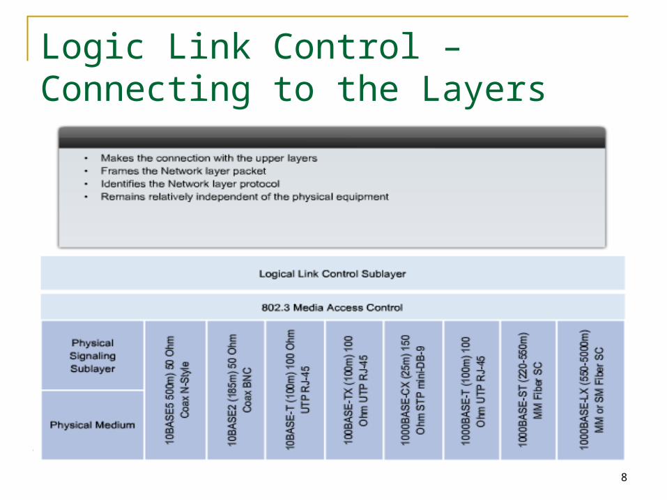
The Logical Link Control (LLC) sublayer remains relatively independent of the physical equipment that will be used for the communication process.
7
Logic Link Control – Connecting to the Layers The IEEE 802.2 standard describes the LLC
sublayer functions, and the 802.3 standard describes the MAC sublayer and the Physical layer functions.
Logical Link Control handles the communication between the upper layers and the networking software, and the lower layers, typically the hardware.
The LLC sublayer takes the network protocol data, which is typically an IPv4 packet, and adds control information to help deliver the packet to the destination node. Layer 2 communicates with the upper layers through LLC.
8
Logic Link Control – Connecting to the Layers
9
Logic Link Control – Connecting to the Layers LLC is implemented in software, and its
implementation is independent of the physical equipment.
In a computer, the LLC can be considered the driver software for the Network Interface Card (NIC).
The NIC driver is a program that interacts directly with the hardware on the NIC to pass the data between the media and the Media Access Control sublayer.

10
MAC – Getting Data to the Media

11
MAC – Getting Data to the Media The underlying logical topology of Ethernet is a
multi-access bus. This means that all the nodes (devices) in that
network segment share the medium. This further means that all the nodes in that
segment receive all the frames transmitted by any node on that segment.
Ethernet provides a method for determining how the nodes share access to the media. The media access control method for classic Ethernet is Carrier Sense Multiple Access with Collision Detection (CSMA/CD).

12
Physical Implementations of Ethernet The success of Ethernet is due to the
following factors: Simplicity and ease of maintenance Ability to incorporate new technologies Reliability Low cost of installation and upgrade
The introduction of Gigabit Ethernet has extended the original LAN technology to distances that make Ethernet a Metropolitan Area Network (MAN) and WAN standard.

13
Physical Implementations of Ethernet

14
Ethernet – Communication through the LAN Historic Ethernet Ethernet Collision Management Moving to 1 Gbps and Beyond
15
Historic Ethernet
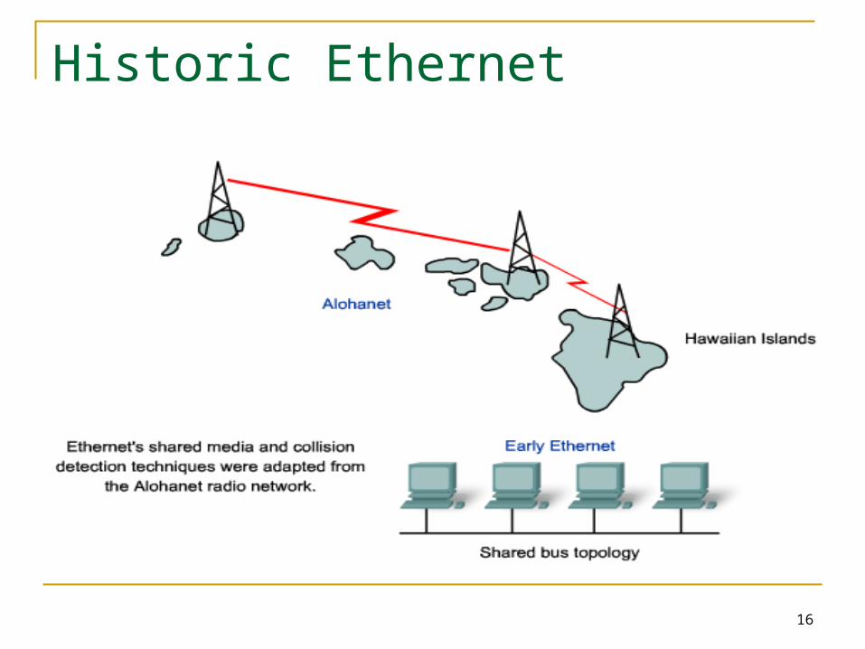
Established in 1970 with a program called Alohanet Alohanet required all stations to follow a protocol in
which an unacknowledged transmission required re-transmitting after a short period of waiting.
The techniques for using a shared medium in this way were later applied to wired technology in the form of Ethernet.
Ethernet was designed to accommodate multiple computers that were Interconnected on a shared bus topology.
16
Historic Ethernet
17
Historic Ethernet
Early versions of Ethernet were known as Thicknet, (10BASE5) and Thinnet (10BASE2).
10BASE5: Thicknet, coaxial, 500m 10BASE2: Thinnet, flexiable, coaxial, 185m The original thick coaxial and thin coaxial
physical media were replaced by early categories of UTP cables (easier to work with, lightweight, and less expensive)

18
Historic Ethernet
The physical topology was also changed to a star topology using hubs.

19
Ethernet Collision Management – Migration to Ethernet Switches
20
Ethernet Collision Management The introduction of switches to replace hubs in
Ethernet-based networks Switches can control the flow of data by isolating
each port and sending a frame only to its proper destination (if the destination is known), rather than send every frame to every device.
The switch reduces the number of devices receiving each frame, which in turn reduces or minimizes the possibility of collisions.
The later introduction of full-duplex communications (having a connection that can carry both transmitted and received signals at the same time), has enabled the development of 1Gbps Ethernet and beyond.
21
Moving to 1 Gbps and Beyond The increasing use of Voice over IP (VoIP) and
multimedia services requires connections that are faster than 100 Mbps Ethernet.
Upgrading to 1 Gbps Ethernet does not always mean that the existing network infrastructure of cables and switches has to be completely replaced.
Some of the equipment and cabling in modern, well-designed and installed networks may be capable of working at the higher speeds with only minimal upgrading.
This capability has the benefit of reducing the total cost of ownership of the network.
22
Moving to 1 Gbps and Beyond -Ethernet Beyond the LAN The increased cabling distances enabled by
the use of fiber-optic cable in Ethernet-based networks has resulted in a blurring of the distinction between LANs and WANs.
Ethernet was initially limited to LAN cable systems within single buildings, and then extended to between buildings. It can now be applied across a city in what is known as a Metropolitan Area Network (MAN).

23
The Ethernet Frame
The Frame – Encapsulating the Packet The Ethernet MAC Address Hexadecimal Numbering and Addressing Another Layer of Addressing Ethernet Unicast, Multicast & Broadcast
24
The Frame – Encapsulating the Packet The Ethernet frame structure adds headers
and trailers around the Layer 3 PDU to encapsulate the message being sent.
Each section of the frame is called a field. The most significant difference between the
two standards are the addition of a Start Frame Delimiter (SFD) and the change of the Type field to a Length field in the 802.3

25
The Frame – Encapsulating the Packet

26
The Frame – Encapsulating the Packet (Ethernet Frame Size) From 64 to 1518 bytes (Destination MAC
Address field to the FCS field) Extend to 1522 byes for VLAN technology If the size of a transmitted frame is less than
the minimum or greater than the maximum, the receiving device drops the frame.
Dropped frames are likely to be the result of collisions or other unwanted signals and are therefore considered invalid.
27
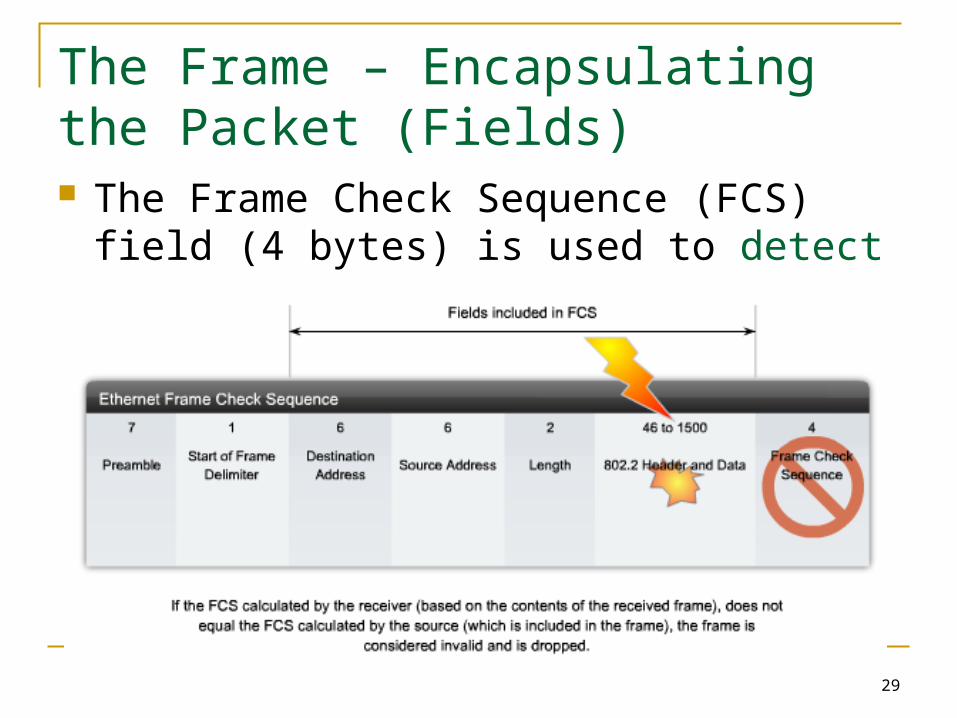
The Frame – Encapsulating the Packet (Fields) The Preamble (7 bytes) and Start Frame Delimiter
(SFD) (1 byte) fields are used for synchronization between the sending and receiving devices. Essentially, the first few bytes tell the receivers to get ready to receive a new frame.
The Destination MAC Address field (6 bytes) is the identifier for the intended recipient.
The Source MAC Address field (6 bytes) identifies the frame's originating NIC or interface.
The Length field defines the exact length of the frame's data field. >1536 => data field are decode according to the Ethernet II < 1500 => 802.3

28
The Frame – Encapsulating the Packet (Fields) The Data and Pad fields (46 - 1500 bytes)
contains the encapsulated data from a higher layer, which is a generic Layer 3 PDU, or more commonly, an IPv4 packet.
All frames must be at least 64 bytes long. If a small packet is encapsulated, the Pad is
used to increase the size of the frame to this minimum size.
29
The Frame – Encapsulating the Packet (Fields) The Frame Check Sequence (FCS) field (4
bytes) is used to detect errors in a frame.
30
The Ethernet MAC Address
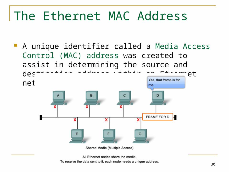
A unique identifier called a Media Access Control (MAC) address was created to assist in determining the source and destination address within an Ethernet network.
31
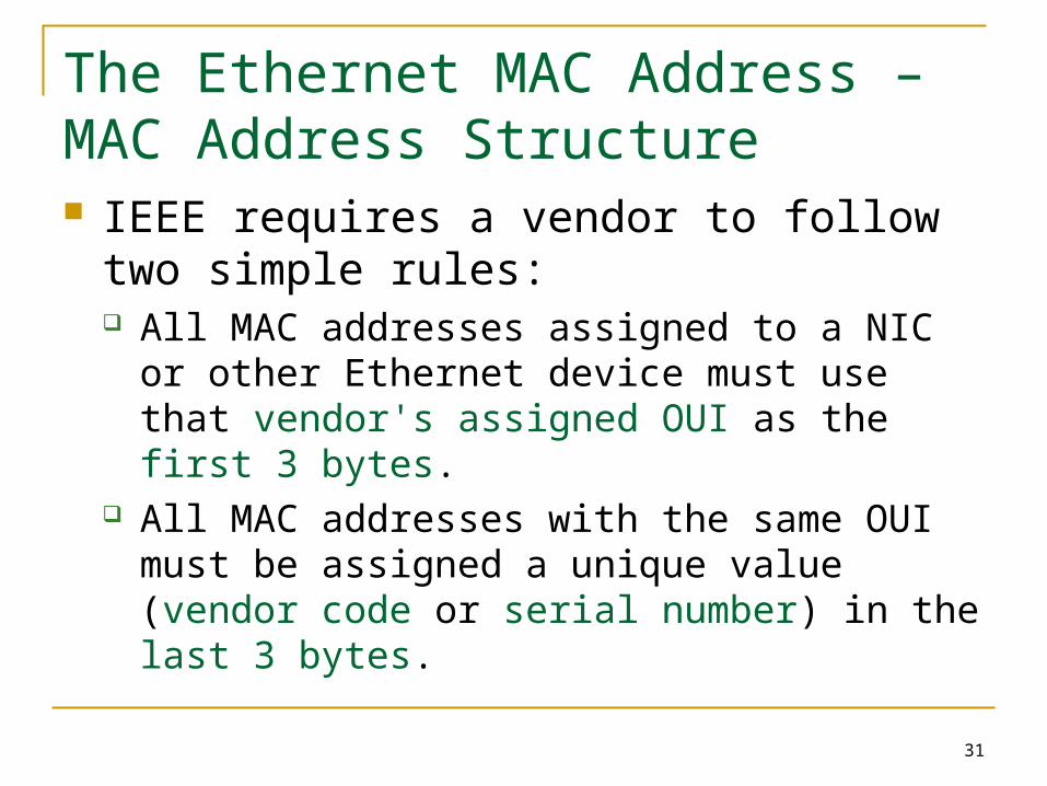
The Ethernet MAC Address – MAC Address Structure IEEE requires a vendor to follow two simple
rules: All MAC addresses assigned to a NIC or other
Ethernet device must use that vendor's assigned OUI as the first 3 bytes.
All MAC addresses with the same OUI must be assigned a unique value (vendor code or serial number) in the last 3 bytes.

32
The Ethernet MAC Address – Network Devices Each NIC in the network views the information to
see if the MAC address matches its physical address. If there is no match, the device discards the frame.
When the frame reaches the destination where the MAC of the NIC matches the destination MAC of the frame, the NIC passes the frame up the OSI layers, where the decapsulation process take place.
All devices connected to an Ethernet LAN have MAC-addressed interfaces.

33
Hexadecimal Numbering and Addressing

34
Another Layer of Addressing
OSI Data Link layer (Layer 2) physical addressing, implemented as an Ethernet MAC address, is used to transport the frame across the local media. non-hierarchical no meaning outside the local network media
Network layer (Layer 3) addresses, such as IPv4 addresses, provide the ubiquitous, logical addressing that is understood at both source and destination.
The Network layer address enables the packet to be forwarded toward its destination.
The Data Link layer address enables the packet to be carried by the local media across each segment.
35
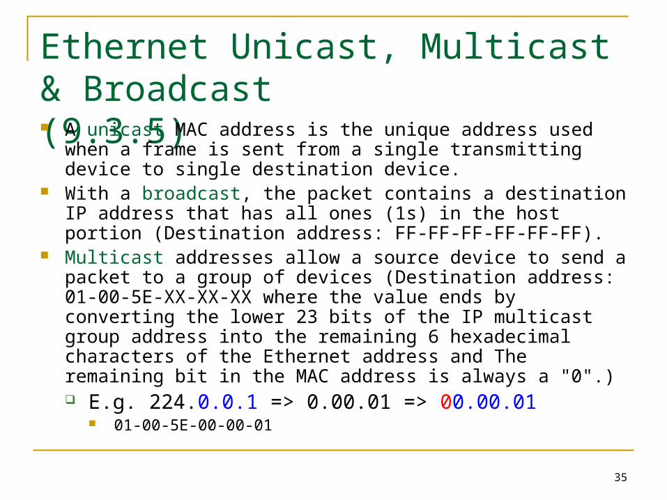
Ethernet Unicast, Multicast & Broadcast(9.3.5) A unicast MAC address is the unique address used when a frame is
sent from a single transmitting device to single destination device. With a broadcast, the packet contains a destination IP address that
has all ones (1s) in the host portion (Destination address: FF-FF-FF-FF-FF-FF).
Multicast addresses allow a source device to send a packet to a group of devices (Destination address: 01-00-5E-XX-XX-XX where the value ends by converting the lower 23 bits of the IP multicast group address into the remaining 6 hexadecimal characters of the Ethernet address and The remaining bit in the MAC address is always a "0".) E.g. 224.0.0.1 => 0.00.01 => 00.00.01
01-00-5E-00-00-01

36
Ethernet Media Access Control Media Access Control in Ethernet CSMA/CD – The Process Ethernet Timing Interframe Spacing and Backoff

37
Media Access Control in Ethernet In a shared media environment, all devices
have guaranteed access to the medium, but they have no prioritized claim on it.
If more than one device transmits simultaneously, the physical signals collide and the network must recover in order for communication to continue.
Collisions are the cost that Ethernet pays to get the low overhead associated with each transmission.
38
Media Access Control in Ethernet Ethernet uses Carrier Sense Multiple Access
with Collision Detection (CSMA/CD) to detect and handle collisions and manage the resumption of communications.
A device can then determine when it can transmit.
When a device detects that no other computer is sending a frame, or carrier signal, the device will transmit, if it has something to send.

39
CSMA/CD – The Process
Carrier Sense All network devices that have messages to send
must listen before transmitting. If a device detects a signal from another device, it
will wait for a specified amount of time before attempting to transmit.
While this transmission is occurring, the device continues to listen for traffic or collisions on the LAN.
After the message is sent, the device returns to its default listening mode.

40
CSMA/CD – The Process Multi-access
If the distance between devices is such that the latency of one device's signals means that signals are not detected by a second device, the second device may start to transmit, too.
The media now has two devices transmitting their signals at the same time. Their messages will propagate across the media until they encounter each other.
At that point, the signals mix and the message is destroyed.
Although the messages are corrupted, the jumble of remaining signals continues to propagate across the media.

41
CSMA/CD – The Process Collision Detection
When a device is in listening mode, it can detect when a collision occurs on the shared media.
The detection of a collision is made possible because all devices can detect an increase in the amplitude of the signal above the normal level.
Once a collision occurs, the other devices in listening mode - as well as all the transmitting devices - will detect the increase in the signal amplitude.
Once detected, every device transmitting will continue to transmit to ensure that all devices on the network detect the collision.

42
CSMA/CD – The Process Jam Signal and Random Backoff
Once the collision is detected by the transmitting devices, they send out a jamming signal.
This jamming signal is used to notify the other devices of a collision, so that they will invoke a backoff algorithm.
This backoff algorithm causes all devices to stop transmitting for a random amount of time, which allows the collision signals to subside.
After the delay has expired on a device, the device goes back into the "listening before transmit" mode.
A random backoff period ensures that the devices that were involved in the collision do not try to send their traffic again at the same time, which would cause the whole process to repeat.
But, this also means that a third device may transmit before either of the two involved in the original collision have a chance to re-transmit.
43
CSMA/CD – The Process (Activity: 9.4.2) Because of the rapid growth of the Internet:
More devices are being connected to the network. Devices access the network media more frequently. Distances between devices are increasing
Hubs and repeaters are intermediary devices that extend the distance that Ethernet cables can reach.
The connected devices that access a common media via a hub or series of directly connected hubs make up what is known as a collision domain.
A collision domain is also referred to as a network segment. Hubs and repeaters therefore have the effect of increasing the size of the collision domain.
An increased number of collisions reduces the network's efficiency and effectiveness until the collisions become a nuisance to the user.
44
Ethernet Timing Latency (遲滯 )
The electrical signal that is transmitted takes a certain amount of time (latency) to propagate (travel) down the cable.
Each hub or repeater in the signal's path adds latency as it forwards the bits from one port to the next.
This accumulated delay increases the likelihood that collisions will occur because a listening node may transition into transmitting signals while the hub or repeater is processing the message.

45
Ethernet Timing Timing and Synchronization
In half-duplex mode, if a collision has not occurred, the sending device will transmit a preamble (64 bits) of timing synchronization information.
The sending device will then transmit the complete frame.
< 10 Mbps, asynchronous (8 bit timing information)
> 10 Mbps, synchronous (no timing information)

46
Ethernet Timing Bit Time
A period of time is required for a bit to be placed and sensed on the media
At 100 Mbps, the device timing is barely able to accommodate 100 meter cables.
At 1000 Mbps, special adjustments are required because nearly an entire minimum-sized frame would be transmitted before the first bit reached the end of the first 100 meters of UTP cable.
For this reason, half-duplex mode is not permitted in 10-Gigabit Ethernet.
These timing considerations have to be applied to the interframe spacing and backoff times.

47
Ethernet Timing Slot Time
Is the time takes for an electronic pulse to travel the length of the maximum theoretical distance between two nodes. It is also the time that a transmitting station waits before attempting to retransmit following a collision
In half-duplex Ethernet, where data can only travel in one direction at once, slot time becomes an important parameter in determining how many devices can share a network.
48
Ethernet Timing Slot Time
The 512-bit slot time establishes the minimum size of an Ethernet frame as 64 bytes. Any frame less than 64 bytes in length is considered a "collision fragment" or "runt frame" and is automatically discarded by receiving stations.
The slot time establishes a limit on the maximum size of a network's segments. If the network grows too big, late collisions can occur. Late collisions are considered a failure in the network because the collision is detected too late by a device during the frame transmission to be automatically handled by CSMA/CD.
Slot time is calculated assuming maximum cable lengths on the largest legal network architecture. All hardware propagation delay times are at the legal maximum and the 32-bit jam signal is used when collisions are detected.
49
Interframe Spacing and Backoff Interframe Spacing
The Ethernet standards require a minimum spacing between two non-colliding frames.
This gives the media time to stabilize after the transmission of the previous frame and time for the devices to process the frame.
After a frame has been sent, all devices on a 10 Mbps Ethernet network are required to wait a minimum of 96 bit times (9.6 microseconds) before any device can transmit its next frame.
Interframe time reduces as Ethernet speed increases.
50
Interframe Spacing and Backoff Jam Signal
As soon as a collision is detected, the sending devices transmit a 32-bit "jam" signal that will enforce the collision. This ensures all devices in the LAN to detect the collision.
It is important that the jam signal not be detected as a valid frame; otherwise the collision would not be identified. The most commonly observed data pattern for a jam signal is simply a repeating 1, 0, 1, 0 pattern, the same as the Preamble.
This distinguishes the corrupted, partially transmitted messages are often referred to as collision fragments or runts.

51
Interframe Spacing and Backoff Backoff Timing
After a collision occurs and all devices allow the cable to become idle (each waits the full interframe spacing), the devices whose transmissions collided must wait an additional - and potentially progressively longer - period of time before attempting to retransmit the collided frame.
The waiting period is intentionally designed to be random so that two stations do not delay for the same amount of time before retransmitting, which would result in more collisions.
If media congestion results in the MAC layer unable to send the frame after 16 attempts, it gives up and generates an error to the Network layer.
52
Ethernet Physical Layer
Overview of Ethernet Physical Layer 10 and 100 Mbps Ethernet 1000 Mbps Ethernet Ethernet – Future Options
53
Overview of Ethernet Physical Layer Ethernet is covered by the IEEE 802.3
standards. Four data rates are currently defined for operation over optical fiber and twisted-pair cables: 10 Mbps - 10Base-T Ethernet 100 Mbps - Fast Ethernet 1000 Mbps - Gigabit Ethernet 10 Gbps - 10 Gigabit Ethernet
54
10 and 100 Mbps Ethernet
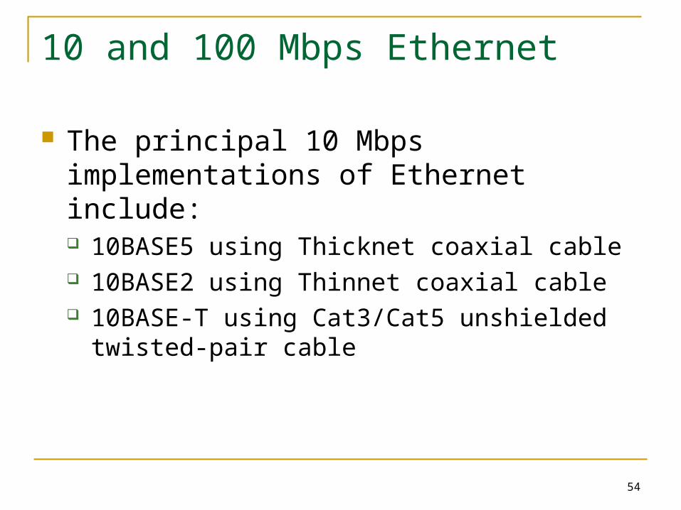
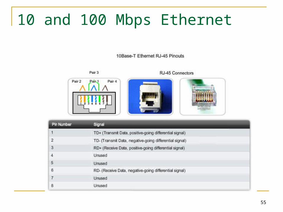
The principal 10 Mbps implementations of Ethernet include: 10BASE5 using Thicknet coaxial cable 10BASE2 using Thinnet coaxial cable 10BASE-T using Cat3/Cat5 unshielded twisted-
pair cable
55
10 and 100 Mbps Ethernet
56
100 Mbps Ethernet
100 Mbps Ethernet, also known as Fast Ethernet, can be implemented using twisted-pair copper wire or fiber media. The most popular implementations of 100 Mbps Ethernet are: 100BASE-TX using Cat5 or later UTP 100BASE-FX using fiber-optic cable
57
100 Mbps Ethernet
100BASE-TX was designed to support transmission over either two pairs of Category 5 UTP copper wire or two strands of optical fiber. The 100BASE-TX implementation uses the same two pairs and pinouts of UTP as 10BASE-T. However, 100BASE-TX requires Category 5 or later UTP. The 4B/5B encoding is used for 100BASE-T Ethernet.
The 100BASE-FX standard uses the same signaling procedure as 100BASE-TX, but over optical fiber media rather than UTP copper.
58
1000 Mbps Ethernet
The development of Gigabit Ethernet standards resulted in specifications for UTP copper, single-mode fiber, and multimode fiber.
The question of performance is based on how fast the network adapter or interface can change voltage levels and how well that voltage change can be detected reliably 100 meters away, at the receiving NIC or interface.
Data transmission is more efficient when codes are used to represent the binary bit stream. Encoding the data enables synchronization, efficient usage of bandwidth, and improved signal-to-noise ratio characteristics.
59
1000 Mbps Ethernet - 1000BASE-T 1000BASE-T Ethernet provides full-duplex transmission using all
four pairs in Category 5 or later UTP cable. Gigabit Ethernet over copper wire enables an increase from 100
Mbps per wire pair to 125 Mbps per wire pair, or 500 Mbps for the four pairs.
Each wire pair signals in full duplex, doubling the 500 Mbps to 1000 Mbps.
1000BASE-T uses 4D-PAM5 line encoding to obtain 1 Gbps data throughput.
It translates an 8-bit byte of data into a simultaneous transmission of four code symbols (4D), which are sent over the media, one on each pair, as 5-level Pulse Amplitude Modulated (PAM5) signals.
During data transmission periods, up to 17 voltage levels are found on the cable.
60
1000 Mbps Ethernet - 1000BASE-SX and 1000BASE-LX The fiber versions of Gigabit Ethernet - 1000BASE-SX and
1000BASE-LX - offer the following advantages over UTP: noise immunity, small physical size, and increased unrepeated distances and bandwidth.
All 1000BASE-SX and 1000BASE-LX versions support full-duplex binary transmission at 1250 Mbps over two strands of optical fiber. The transmission coding is based on the 8B/10B encoding scheme. Because of the overhead of this encoding, the data transfer rate is still 1000 Mbps.
Each data frame is encapsulated at the Physical layer before transmission, and link synchronization is maintained by sending a continuous stream of IDLE code groups during the interframe spacing.
The principal differences among the 1000BASE-SX and 1000BASE-LX fiber versions are the link media, connectors, and wavelength of the optical signal.
61
Ethernet – Future Options
The IEEE 802.3ae standard was adapted to include 10 Gbps, full-duplex transmission over fiber-optic cable. The 802.3ae standard and the 802.3 standards for the original Ethernet are very similar. 10-Gigabit Ethernet (10GbE) is evolving for use not only in LANs, but also for use in WANs and MANs.
Because the frame format and other Ethernet Layer 2 specifications are compatible with previous standards, 10GbE can provide increased bandwidth to individual networks that is interoperable with the existing network infrastructure.
62
Ethernet – Future Options 10Gbps can be compared to other varieties of
Ethernet in these ways: Frame format is the same, allowing interoperability
between all varieties of legacy, fast, gigabit, and 10 gigabit Ethernet, with no reframing or protocol conversions necessary.
Bit time is now 0.1 ns. All other time variables scale accordingly.
Because only full-duplex fiber connections are used, there is no media contention and CSMA/CD is not necessary.
The IEEE 802.3 sublayers within OSI Layers 1 and 2 are mostly preserved, with a few additions to accommodate 40 km fiber links and interoperability with other fiber technologies.

63
Ethernet – Future Ethernet Speeds Although 1-Gigabit Ethernet is now widely
available and 10-Gigabit products are becoming more available, the IEEE and the 10-Gigabit Ethernet Alliance are working on 40-, 100-, or even 160-Gbps standards.
The technologies that are adopted will depend on a number of factors, including the rate of maturation of the technologies and
standards, the rate of adoption in the market, and the cost of emerging products.
64
Hubs and Switches
Legacy Ethernet – Using Hubs Ethernet – Using Switches Switches – Selective Forwarding Ethernet – Comparing Hubs and Switches

65
Legacy Ethernet – Using Hubs Sharing media among devices creates significant issues as the
network grows. Scalability: With each increase in the number of devices on the
media, performance is degraded. Latency: Increasing the length of media or the number of hubs
and repeaters connected to a segment results in increased latency.
Network Failure: Ethernet shares the media, any device in the network could potentially cause problems for other devices. If any device connected to the hub generates detrimental traffic, the communication for all devices on the media could be impeded.
Collisions: A network with a larger number of nodes on the same segment has a larger collision domain and typically has more traffic. As the amount of traffic in the network increases, the likelihood of collisions increases.
66
Ethernet – Using Switches
Switches allow the segmentation of the LAN into separate collision domains.
Each port of the switch represents a separate collision domain and provides the full media bandwidth to the node or nodes connected on that port.
With fewer nodes in each collision domain, there is an increase in the average bandwidth available to each node, and collisions are reduced.

67
Ethernet – Using Switches In a LAN where all nodes are connected
directly to the switch, the throughput of the network increases dramatically. The three primary reasons for this increase are: Dedicated bandwidth to each port Collision-free environment Full-duplex operation
68
Switches – Selective Forwarding Ethernet switches selectively forward individual
frames from a receiving port to the port where the destination node is connected.
This selective forwarding process can be thought of as establishing a momentary point-to-point connection between the transmitting and receiving nodes.
The connection is made only long enough to forward a single frame. During this instant, the two nodes have a full bandwidth connection between them and represent a logical point-to-point connection.
69
Switches – Selective Forwarding The switch maintains a table, called a MAC
table. that matches a destination MAC address with the port used to connect to a node.
The MAC table can be referred to by many different names.
It is often called the switch table. Because switching was derived from an older technology called transparent bridging, the table is sometimes called the bridge table.
70
Switches – Selective Forwarding To accomplish their purpose, Ethernet LAN switches
use five basic operations: Learning: allows MAC addresses and their corresponding
ports mappings form the source MAC address Aging: timestamp is used as a means for removing old
entries in the MAC table. Flooding: The process of sending a frame to all segments
is known as flooding. Selective Forwarding: The process of examining a frame's
destination MAC address and forwarding it out the appropriate port. This is the central function of the switch.
Filtering: a frame is not forwarded.

71
Ethernet – Comparing Hubs and Switches Activity: Refer to 9.6.4
72
Address Resolution Protocol (ARP) The ARP Process – Mapping IP to MAC
Addresses The ARP Process – Destinations outside the
Local Network The ARP Process – Removing Address
Mappings ARP Broadcasts – Issues
73
The ARP Process – Mapping IP to MAC Addresses (9.7.1) For a frame to be placed on the LAN media, it must
have a destination MAC address. The node refers to a table in its memory to find the
Data Link layer address that is mapped to the destination IPv4 address.
This table is called the ARP table or the ARP cache. The ARP table is maintained dynamically. The ARP processes then send out an ARP request
packet to discover the MAC address of the destination device on the local network. If a device receiving the request has the destination IP address, it responds with an ARP reply.
74
The ARP Process – Destinations outside the Local (9.7.2) If the destination IPv4 host is not on the local
network, the source node needs to deliver the frame to the router interface that is the gateway or next hop used to reach that destination.
The source node will use the MAC address of the gateway as the destination address for frames containing an IPv4 packet addressed to hosts on other networks.
The gateway address of the router interface is stored in the IPv4 configuration of the hosts.
To provide a MAC address for these hosts, a router interface may use a proxy ARP to respond on behalf of these remote hosts.
75
The ARP Process – Removing Address Mappings An ARP cache timer removes ARP entries
that have not been used for a specified period of time.
Commands may also be used to manually remove all or some of the entries in the ARP table.

76
ARP Broadcasts – Issues Overhead on the Media
As a broadcast frame, an ARP request is received and processed by every device on the local network.
If a large number of devices were to be powered up and all start accessing network services at the same time, there could be some reduction in performance for a short period of time.
Security The use of ARP can lead to a potential security risk. ARP
spoofing, or ARP poisoning, is a technique used by an attacker to inject the wrong MAC address association into a network by issuing fake ARP requests. An attacker forges the MAC address of a device and then frames can be sent to the wrong destination.
Manually configuring static ARP associations is one way to prevent ARP spoofing. Authorized MAC addresses can be configured on some network devices to restrict network access to only those devices listed.