Embed Size (px)
DESCRIPTION
Nuclear Reactors
Citation preview

Nuclear Safety
Design and Safety Features of Nuclear Reactors Neighbouring the Nordic Countries
TemaNord 1994:595
&commissioned/ reactors not yet In
Power reactors
*
I 1 U ‘
1

Design and Saf ety Features ofNuclear Reactors Neighbouringthe Nordic Countries

Design and Saf ety Features ofNuclear Reactors Neighbouringthe Nordic CountriesFinal Report of the Nordic Nuclear
Saf ety Research Project SIK-3
Edited byErik NonbølMay 1994
TemaNord 1994:595

Design and Safety Features of Nuclear Reactors Neighbouringthe Nordic CountriesTemaNord 1994:595Copyright: The Nordic Council of Ministers, Copenhagenl994ISBN 92 9120 521 4ISSN 0908-6692Printing and distribution: Nordic Council of Ministers, CopenhagenPrinted on Paper Approved by the Nordic Environmental LabellingInformation about the NKS reports can be obtained from:NKSP.O.Box49DK-4000 RoskildeTelefax (+45) 46 32 22 06
The Nordic Council of Ministerswas established in 1971. It submits proposals on co-operation between the governmentsof the five Nordic countries to the Nordic Council, implements the Council'srecommendations and reports on results, while directing the work carried out in thetargeted areas. The Prime Ministers of the five Nordic countries assume overallresponsibility for the co-operation measures, which åre co-ordinated by the ministersfor co-operation and the Nordic Co-operation Committee. The composition of theCouncil of Ministers varies, depending on the nature of the issue to be treated.
The Nordic Councilwas formed in 1952 to promote co-operation between the parliaments and governmentsof Denmark, Iceland, Norway and Sweden. Finland joined in 1955. At the sessions heldby the Council, representatives from the Faroe Islands and Greenland form part of theDanish delegation, while Åland is represented on the Finnish delegation. The Councilconsists of 87 elected members - all of whom åre members of parliament. The NordicCouncil takes initiatives, acts in a consultative capacity and monitors co-operationmeasures. The Council operates via its institutions: the Plenary Assembly, thePresidium, and standing committees.

Abstract
The Chernobyl accident in 1986 revealed a remarkable lack of information in theWestern countries on design and operation of Russian reactors. Therefore a Nordicproject was started with the purpose of collecting information on the design andsafety features of reactors neighbouring the Nordic countries. The nuclear powerplants included åre the RBMK reactors Ignalina and Leningrad, the WER reactorsGreifswald and Kola, the BWR reactors Brunsbuttel and Krummel and the PWRreactors Stade and Brokdorf, all located within 100-450 km from the borders of aNordic country. Marine reactors supposed to operate in the Nordic seas åre alsoconsidered. Detailed reports for each power plant and marine reactors have beenmade.
Key words: RBMK reactors, WER reactors, Ignalina NPP, Leningrad NPP,Kola NPP, Brunsbuttel NPP, Krummel NPP, Brokdorf NPP, StadeNPP, ship reactors, submarine reactors, icebreaker reactors,nuclear safety criteria.


Summary
When the Chernobyl accident occurred in 1986 it appeared that knowledgeavailable in the Nordic countries, i.e. Norway, Sweden, Finland, Iceland andDenmark, especially about the Eastern type of reactors was very poor. The lack ofinformation applied to technical features, safety related factors, exact location etc.and also to the management set-up in the utilities and at the competent authorities.The information that was actually available was difficult to get hold of, so that thecompetent authorities could not easily utilize it.
In the SIK-3 project, information is collected in a systematic way about nuclearpower plants located close to borders of the Nordic countries. The informationincludes design features and operational practices that åre significant for plantsafety, provided the data have been available. The data åre presented in a uniformmanner for all the reactors, so relevant information can easily be found in anemergency situation. Examples of information that is provided include map of sitelocation, plant arrangement, safety criteria, comparison with similar reactor types,organization of the authorities etc.
The data of each plant åre assembled in reports and åre also available on a PC-database for easy updating. The information in these reports can be used forqualitative evaluations, but more ample information would be required in order toperform probabilistic safety studies. In case of a nuclear accident the informationcould be used to evaluate the progression of the accident and also to evaluate thepotential consequences on the environment.
The nuclear power plants included in this project åre the RBMK reactors Ignalinaand Leningrad, the WER reactors Greifswald and Kola, the BWR reactorsBrunsbiittel and Krummel and the PWR reactors Stade and Brokdorf, all of whichåre located within 100-450 km from the borders of a Nordic country.
The reports include essential facts and special safety features of each reactor type.However, it was not intended to include a thorough evaluation of the safetycondition of each particular plant.
Some of the data åre confidential and therefore resrrictions have been imposed onthe distribution of the detailed reports.

Nuclear powered icebreakers and submarines åre known to operate in the seasclose to the Nordic countries. Information has therefore been collected on thedesign and safety features of marine reactors to the extent the information hasbeen available. The reports on ship reactors can be used as a basis for riskassessment in case of a future nuclear ship accident or in case of release ofradioactive material near the sea bottom from disposed reactors or from sunkensubmarines.
The project has given rise to a contact net among the Nordic nuclear authoritiesand a knowledge base of, especially, the Eastern type of reactors. Therefore, incase of a nuclear accident in a neighbouring country, the Nordic nuclearauthorities will be better prepared than was the case at the time of the Chernobylaccident.
IV

Sammenfatning
Da Chernobyl ulykken skete i 1986, viste det sig, at den tilgængelige viden iNorden vedrørende især de østlige kernekraftreaktorer var utilstrækkelig. Denmanglende viden gjaldt tekniske egenskaber, sikkerhedsrelaterede faktorer,placering samt organisationsstrukturen af både de østlige værker og de østligenukleare myndigheder. De informationer, som fandtes i Norden, var vanskelige atfå fat på, ligesom de var svære at udnytte for myndighederne.
I SIK-3 projektet er informationerne om kernekraftværkerne tæt ved de nordiskegrænser samlet på en systematisk måde. Informationerne omfatter designegenskaber og driftsforhold, som har sikkerhedsmæssig betydning for anlægget, idet omfang oplysningerne har været til stede. Oplysningerne præsenteres på enensartet måde for alle nukleare anlæg, således at de relevante detaljer hurtigt kanfindes i tilfælde af en katastrofesituation. Eksempler på den information, som erinkluderet, er kort over placering af kernekraftværket, individuel placering afbygningerne, sikkerhedskriterier, sammenligning med reaktorer af lignende type,organisering af myndigheder o.s.v.
Oplysningerne om hvert anlæg er samlet i rapporter og er også tilgængelige på enPC-database for at lette fremtidige opdateringer. Informationerne i disse rapporterkan anvendes til kvalitative vurdereringer af sikkerheden på de enkelte anlæg,hvorimod egentlige risikostudier kræver adgang til mere detaljerede oplysninger.I tilfælde af at et uheld skulle indtræffe på et nabokernekraftværk, kan deudarbejdede rapporter anvendes til at vurdere, hvorledes uheldet kan tænkes atudvikle sig, herunder også vurdere mulige konsekvenser for omgivelserne.
De nukleare anlæg, som er behandlet i projektet, omfatter RBMK reaktorerneIgnalina og Leningrad, WER reaktorerne Greifswald og Kola, BWR reaktorerneBrunsbuttel og Krummel og PWR reaktorerne Stade og Brokdorf, alle placeret fra100-450 km fra de nordiske grænser.
Rapporterne afspejler konstruktionsdata og specielle sikkerhedsegenskaber forhver reaktortype. Derimod har det ikke været hensigten i dette projekt atinkludere en egentlig vurdering af sikkerhedstilstanden for det enkelte anlæg.
Nogle af informationerne er fortrolige, og derfor har det været nødvendigt atpålægge restriktioner på distributionen af rapporterne.

Det vides, at isbrydere og undervandsbåde, som er drevet af nukleare reaktorer,opererer i de nordiske farvandene. Derfor er der i projektet indsamlet informationomkring sikkerhedsforhold af disse marine reaktorer, i det omfang oplysningernehar været tilgængelige. Rapporterne om skibsreaktorer kan anvendes somgrundlag for at bedømme risikoen for eventuelle fremtidige uheld med nukleareskibe. Ligeledes kan de anvendes i forbindelse med vurdering af frigørelse afradioaktivt materiale fra allerede sunkne skibe og undervandsbåde.
SIK-3 projektet har givet anledning til etablering af et kontaktnet mellem denordiske nukleare myndigheder, samt opbygning af en database omkring specieltreaktorer af østlig oprindelse. I tilfælde af et fremtidigt uheld i etnabokernekraftværk vil de nukleare myndigheder i Norden derfor være langtbedre rustet, end tilfældet var, da Chernobyl katastrofen skete.
vi

The project group of SIK-3
Hannu Ollikkala
Tore Nilsson
Jean-Pierre Bento
Anders SiljestromBengt G. Olofsson
Per I. Wethe
Egil Stokke
Bjørn Thorlaksen
Erik Nonbølproject leader
STUKThe Finnish Centre for Radiationand Nuclear SafetyP.O. Box 14FIN-00881 HelsinkiFinland
SKISwedish Nuclear Power InspectorateP.O. Box 27106S-102 52 StockholmSweden
KSUNuclear Training and Safety CenterS-611 82NykopingSweden
International General Electric ABP.O. Box 1203S-164 28 KistaSweden
IFEInstitute for Energy TechniqueP.O. Box 40N-2007 KjellerNorway
OECD Halden Reactor ProjectP.O. Box 173N-1750 HaldenNorway
Danish Nuclear InspectorateDatavej 16DK-3460 BirkerødDenmark
Risø National LaboratoryP.O. Box 49DK-4000 RoskildeDenmark
Vil


Contents
1 Introduction . . . . . . . . . . . . . . . . . . . . . . . . . . . . . . . . . . . . . . . . . . . . l1.1 Background . . . . . . . . . . . . . . . . . . . . . . . . . . . . . . . . . . . . . . . . ll .2 Objectives . . . . . . . . . . . . . . . . . . . . . . . . . . . . . . . . . . . . . . . . . l1.3 Scope . . . . . . . . . . . . . . . . . . . . . . . . . . . . . . . . . . . . . . . . . . . . . 2
2 Neighbouring Nuclear Power Plants . . . . . . . . . . . . . . . . . . . . . . . . . 32.1 Reactors considered . . . . . . . . . . . . . . . . . . . . . . . . . . . . . . . . . . 32.2 Disposition of the data . . . . . . . . . . . . . . . . . . . . . . . . . . . . . . . . 42.3 Validation of the data . . . . . . . . . . . . . . . . . . . . . . . . . . . . . . . . . 5
3 Basic nuclear safety criteria . . . . . . . . . . . . . . . . . . . . . . . . . . . . . . . . 73.1 Western safety criteria . . . . . . . . . . . . . . . . . . . . . . . . . . . . . . . . 73.2 Eastern safety criteria . . . . . . . . . . . . . . . . . . . . . . . . . . . . . . . . . 93.3 Discussion of the differences between Western and Eastern
safety criteria . . . . . . . . . . . . . . . . . . . . . . . . . . . . . . . . . . . . . . l O
4 Pressurized Water Reactors . . . . . . . . . . . . . . . . . . . . . . . . . . . . . . . 114.1 Stade PWR . . . . . . . . . . . . . . . . . . . . . . . . . . . . . . . . . . . . . . . 114.2 Brokdorf PWR . . . . . . . . . . . . . . . . . . . . . . . . . . . . . . . . . . . . . 134.3 Kola PWR . . . . . . . . . . . . . . . . . . . . . . . . . . . . . . . . . . . . . . . . 174.4 Characteristic differences between Western and Eastern PWR
reactors . . . . . . . . . . . . . . . . . . . . . . . . . . . . . . . . . . . . . . . . . . 20
5 Reactors Cooled By Boiling Water . . . . . . . . . . . . . . . . . . . . . . . . . . 225.1 Brunsbuttel BWR . . . . . . . . . . . . . . . . . . . . . . . . . . . . . . . . . . . 225.2 KriimmelBWR . . . . . . . . . . . . . . . . . . . . . . . . . . . . . . . . . . . . 255.3 Leningrad RBMK . . . . . . . . . . . . . . . . . . . . . . . . . . . . . . . . . . 295.4 Ignalina RBMK . . . . . . . . . . . . . . . . . . . . . . . . . . . . . . . . . . . . 325.5 Characteristic differences between BWR and RBMK
reactors . . . . . . . . . . . . . . . . . . . . . . . . . . . . . . . . . . . . . . . . . . 35
6 Marine reactors . . . . . . . . . . . . . . . . . . . . . . . . . . . . . . . . . . . . . . . . 416.1 Nuclear propulsion plants . . . . . . . . . . . . . . . . . . . . . . . . . . . . 416.2 Nuclear powered submarines . . . . . . . . . . . . . . . . . . . . . . . . . . 426.3 Civilian nuclear snips . . . . . . . . . . . . . . . . . . . . . . . . . . . . . . . . 45
7 Concluding remarks . . . . . . . . . . . . . . . . . . . . . . . . . . . . . . . . . . . . . 47
8 References . . . . . . . . . . . . . . . . . . . . . . . . . . . . . . . . . . . . . . . . . . . . 49
Appendix l : Disposition of the reports . . . . . . . . . . . . . . . . . . . . . 51
Appendix 2 : Rules of distribution for SIK-3 reports . . . . . . . . . . . 57
ix

l Introduction
The purpose of this final report of the SIK-3 project, is to give an overview of theresults obtained in the project with reference to the more detailed data reports.
The report has been aimed at readers with general interest in the subject, whilemore technically interested readers åre referred to the data reports. Particulartechnical terms used in the text åre printed in italic but not further explained inthe present report.
The SIK-3 project is part of the Nordic NKS/SIK programme, carried out during1990-1993. The programme also includes SIK-1, safety evaluation and SIK-2,severe accidents.
Reference 14 summarizes the achievements of the joint Nordic researchprogramme NKS/SIK within reactor safety.
1.1 Background
The Chernobyl accident in 1986 revealed a remarkable lack of information in theWestern countries on the design and operation of Russian reactors. In case of anuclear accident such information is necessary to evaluate the progression of theaccident and also to evaluate the potential consequences on the environment. Insome Nordic countries the nuclear authorities were criticised for this lack ofinformation concerning the Chernobyl type of reactors.
Therefore a Nordic project within the NKS, the Nordic Committee for NuclearSafety Research, was initiated with the title: "Design and Safety Features ofReactors Neighbouring the Nordic Countries".
1.2 Objectives
The objectives of the SIK-3 project were:
• To collect, systematize and evaluate data on the safety of nuclear reactorswithin about 500 km from the border of a Nordic country, i.e. Norway,Sweden, Finland, Iceland and Denmark.
• To enable the nuclear safety authorities in the Nordic countries to respondto general safety related questions concerning a particular nuclear reactor.Such questions could come from politicians, the public or the media.
• To provide the Nordic nuclear safety authorities with diagrams of theimportant safety components of the nuclear plants as a basis for exchangeof information with the plant personnel in an emergency situation.

1.3 Scope
The scope and limitations in the project have been the following:
• Marine reactors supposed to operate in the seas around the Nordiccountries have been included.
• The reports made for each plant do not include an evaluation of the safetycondition of the particular plant. They only state the facts and specialsafety features of each reactor type.
• Only power reactors have been treated in details. Research reactors andwaste storage facilities have not been dealt with. Reactors within theNordic countries have not been included.
• Most of the information for the different plants have been obtained bycontact to the plant owner. Some of the data åre confidential and thereforerestrictions åre imposed on the distribution of the detailed reports.

2 Neighbouring Nuclear Power Plants
2.1 Reactors considered
In table l åre shown the neighbouring nuclear power plants considered with list ofreactor type and distance from the Nordic borders. That comprises reactors withinabout 500 km from the borders of the Nordic countries.
Table 1. Reactors within 500 km from the border ofa Nordic country.Nuclear PowerPlant
Greifswald
Leningrad
Ignalina
Kola
Brunsbuttel
Krummel
Brokdorf
Stade
Marine reactors
Reactor type
WER
RBMK
RBMK
WER
BWR
BWR
PWR
PWR
(PWR)
No of Units
6
4
2
4
1
1
1
1
-
Distance
80 km (DK)
100 km (FIN)
450 km (S)
120 km (FIN)
100 km (DK)
200 km (DK)
100 km (DK)
150 km (DK)
-
WER means Water Water Energy Reactor, (Vodo-Vodjanoj EnergeticheskijReaktor), that is Pressurized Water Reactor ofRussian type.RBMK means Reactor Large Power Channel type, (Reaktor Bol'shojMoshchnost'i Kanal'nogo tipa), that is Boiling-Water-Cooled, Graphite-Moderated, Channel type Reactor ofRussian type.BWR means Boiling Water Reactor of Western design.PWR means Pressurized Water Reactor of Western design.
During the project period it was decided to shut down all WER units at theGreifswald Nuclear Power Plant. All other units shown in the table åre operating.
The marine reactors åre mainly of the pressurized water reactor type but they åremuch smaller in power than normal power reactors.
A map of the neighbouring reactors is shown in Fig. 1.

Figure 1. Map showing the nuclear power plants treated in theproject.
2.2 Disposition of the data
The information collected for each plant is put into a common scheme to facilitatecomparison of data for different plants. For that purpose a modified dispositionfrom a Nordic proposal for organization of a nuclear safety report, (NARS) [1],was applied.

The main items in this disposition åre listed below.
1. Introduction
2. Summary of design data
3. Site and region
4. Safety criteria
5. Technical description and design evaluation
6. Fire protection
7. Plant performance during normal operation
8. Accident analyses
9. Radiation protection
10. Offsite dose assessment
11. Planning, organization and administrative control
12. Organization of the authorities
13. Probabilistic safety assessment
Among the thirteen main items not all have been treated in detail. Item 5,"Technical description and design evaluation", constitutes the mostcomprehensive chapter in the reports, whereas item 8, "Accident analyses", oftenis very short and incomplete due to lack of information.
Appendix l shows the detailed disposition of the reports. Data for some of theitems listed in Appendix l may be missing because the information wasunavailable at the time of writing. However, the items åre still included to assistin a future updating of the reports.
2.3 Validation of the data
In the beginning of the project period it was very difficult to get hold ofinformation about the different reactors.
"Glasnost" and "Perestroika" in the Eastern countries were not implemented inpractice and we were met with a lot of scepticism when we tried to contact themanagers at the Eastern nuclear power plants.

However, during the project period this changed and we were invited to visitsome of the plants. Thus, at Leningrad Nuclear Power Plant, close to SosnovyBor in Russia, one of the SIK-3 project group members spent two weeks, wherehe discussed and corrected the data in the report. At last, the final report wasreviewed by the operating staff at the plant.
The same was the case at the Ignalina Nuclear Power Plant in Lithuania. Amember of the project group payed several visits to the plant and met greathospitality and collaboration from the operating staff. This report was alsoreviewed and corrected by the operators of the plant.
Finally, at the Kola Nuclear Power Plant in the north westerly part of Russia wealso got all the data we requested. Here the final report was also reviewed andapproved by a member of the operating staff.
In faet, at all the three Eastern nuclear power plants the managers were verycontent with the prepared reports which provided them an English description oftheir power plants - useful to offer to all the Western delegations visiting theirnuclear power plants.
In Germany, however, we did not meet the same kind of understanding when weasked for data of their nuclear power plants. At the Krummel and BrunsbuttelNuclear Power Plants located in Schleswig-Holstein by the river Elbe wesucceded in paying a visit and were provided with satisfactory information andwe got our final report reviewed and approved by the managers of the plant.
On the other hånd, at the Stade and Brokdorf Nuclear Power Plants also located inSchleswig-Holstein by the river Elbe our request for information was notanswered at all. Therefore the reports on Stade and Brokdorf åre based oninformation obtained in the open literature and the content is not up-to-date.

3 Bask nuclear safety criteria
The primary risk source in a nuclear reactor is the large amount of radioactivematerial that is generated during operation, primarily the so-called fissionproducts. Even if just a small fraction of these were released to the environment,this could cause severe danger to the biosphere. Therefore one of the main aims innuclear safety work is to prevent release of radioactive fission products into theenvironment.
In order to prevent such a release a number of barriers åre present between theprimary risk source and the environment. The following barriers exist:
• Fuel matrix
• Fuel cladding
• Pressure boundary of primary coolant system including reactor vessel
• Reactor containment
Filter
Furthermore, the nuclear process in the reactor core should be self-controlling orinherently stable during normal conditions, so that small pertubations in processparameters should always cause the reactor to return to normal conditions byitself.
During abnormal conditions the reactor should possess necessary shut-downcapabilities.
3.1 Western safety criteria
Modern Western nuclear safety is based on the application of the defence-in-depthconcept. Also redundancy, diversity, etc. åre applied. Recently also passive ornatural safety features have been discussed.
According to Western safety criteria, protective measures åre realized at fourdifferent safety levels:
• Normal operation
• Transient conditions
• Design basis accidents
• Incidents beyond design basis

The Western safety concepts give priority to measures for accident mitigation andaccident management as well as automatic actions of safety systems. In order torelieve the operators and to reduce the response frequency of protection systems,a progressive concept of protection by automatic control is applied.
The principal aim of all safety considerations is to ensure that the radioactivematerials existing in a nuclear power plant åre confined at all times. In otherwords a nuclear power plant must be designed and operated in such way that at alltimes during specified normal and upset operation and during the so-called designbasis accidents the following conditions (design goals) must be fulfilled:
• The reactor can be safely shut down and kept shut down
• The residual heat can be removed
• The radiation exposure of personnel and radioactive releases to theenvironment must be kept as low as possible.
To achieve this design goal, the safety precaution principles were set up with amultiple level safety concept as follows:
• Assurance of normal operation with the least possible occurrence ofabnormal operating conditions.
• Control of abnormal operating conditions that might occur by usage ofengineered safety features.
• Assurance that design basis accidents stay within given limits andassurance of dose minimization by means of engineered safety features.
Furthermore the so-called "single failure criteria" must be fulfilled, that is thesafety systems must comply with the design criteria even under the assumption ofa single component failure in one of the safety systems.
When analyzing emergency conditions, the following criteria åre applied:
• With the reactor at rated power, a maximum diameter pipe break with atwo-way free outflow of coolant, a so-called guillotine break, ispostulated to be a design basis accident.
As to the fuel, the following design limits åre applied during normal operation:
• The number of failed fuel rods with gas leakage must be less than l .0 %of the total number of fuel rods
• The number of failed fuel rods resulting in direct contact between fueland coolant must be less than 0.1 % of the total number of fuel rods

During accident conditions the following limits åre applied:
• The maximum cladding temperature must be less than 1200 °C
• Local depth of oxidation of fuel cladding must be less than 17 % of theoriginal thickness
3.2 Eastern safety criteria
Modem Eastern nuclear safety is based on the same principles as Western, that isthe application of the defence-in-depth concept. Also redundancy, diversity, etc.åre applied but the Eastern reactors covered in this project only have thefollowing barriers:
• Fuel matrix
• Fuel cladding
• Pressure boundary of primary coolant system including reactor vessel
• Confinement
According to Eastern safety criteria, protective measures åre realized at threedifferent safety levels:
• Normal operation
• Up set conditions
• Design basis accidents
As to the fuel the following design limits åre applied during normal operation:
• The number of failed fuel rods with gas leakage must be less than 1.0%of the total number of fuel rods
• The number of failed fuel rods resulting in direct contact between fueland coolant must be less than 0.1 % of the total number of fuel rods
When analyzing design basis accidents the following criteria åre applied:
• With the reactor at rated power, break of a pipe with a diameter of 500mm and a two-way free outflow of coolant, a so-called guillotine break,is thought to be a design basis accident.
• (For some of the oldest Russian reactors the pipe break diameter waslimited to 32 mm - the pipes then had flow reducing orifices)

During accident conditions the following limits åre applied:
• The maximum cladding temperature must be less than 1200 °C
• Local depth of oxidation of fuel cladding must be less than 18 % of theoriginal thickness
3.3 Discussion of the differences between Western and Easternsafety criteria
The safety criteria defined above åre not complete, several other criteria exist forthe different systems, but those listed åre the main criteria.
There seems to be no big differences between Western and Eastern safety criteria,the main one being the lack of full containment for many of the Russian reactorsbuilt so far, but this is going to change for new reactor constructions.
In general there has been a different approach to safety in the West and the East.
In the West, safety design has often been demonstrated through tests andexperiments in pilot plants. This demonstration has fulfilled two goals, partly ithas shown the functioning of the system in question and partly it has helpedverifying computer codes developed for analysing the safety of nuclear powerplants.
The economy of the new safety features has also played a role in the Westernsafety approach. Several design calculations have been made in order to minimizethe cost and still fulfil the objectives of the safety systems.
In the former Soviet Union safety design was often based on calculations ratherthan experiments. However, often the systems were designed from a conservativepoint of view, that is pipe dimensions, number of pumps, size of vessels etc. werebigger than necessary. In this way compensation was made for some of theuncertainties in the calculations and for the lack of experiments and verificationof codes.
10

4 Pressurized Water Reactors
In the following sections the design data of each PWR reactor treated in theproject will be summarized. These åre the Western type of PWRs, Stade andBrokdorf, and the Eastern WER plant at Kola.
Finally, some characteristic differences between the Western and Eastern type ofpressurized water reactors will be mentioned.
4.1 Stade PWR
The Stade nuclear power plant is located at the river Elbe about 35 km north westof Hamburg, Fig. 2. The pressurized water reactor has an electrical power of 670MW and it has been operating since 1972 [13].
Like other German PWR reactors Stade has a double containment with an innerspherical steel shell and an outer hemispherical concrete structure. The spacebetween the two shells is kept below atmospheric pressure by a ventilation systemand any minor leakage flow from the inner containment is filtered before reachingthe environment.
Figure 2. Location of Stade Nuclear Power Plant, 35 km north west of Hamburg
Table 2. Summary of design data ofthe Stade Nuclear Power Plant
Overall plant
Thermal outputElectrical outputNet electrical outputNet overall efficiency
1892MW662 MW630 MW33.8 %
11

Reactor plant
Coolant and moderaterFuelCladding materialEnrichmentNumber of fuel elementsFuel configurationFuel rod diameterFuel assembly overall lengthAverage specific powerNumber of control assembliesAbsorber materialNumber of reactor coolant loopsOperating pressureReactor coolant flow rateReactor coolant temperatureReactor inlet/outlet
H2OUO2Zircaloy-43.29 % U235157+315X1510.75 mm3655 mm33.8 kW/kgU49Ag80Inl5Cd54154 bar44000 t/h281°C/308 °C284°C/312°C
Reactor building
Spherical steel containmentWall thicknessDesign pressureTest pressureThickness of outer concrete shell
48 m23/30 mm3.8 bar4.24 bar600 mm
Reactor pressure vessel
Inside diameterMaximum overall heightWall thicknessMaterialNozzle diameter inlet/outletTotal weight
4080 mm10400 mm197+7 mm22NiMoCr37700 mm2791
Steam generators
NumberSteam output per unitOverall heightDiameterWall thicknessTube materialWeight
4249 kg/s15600 mm2900/3500 mm50/61 mmIncoloy 8001601
12

Reactor coolant pumps
NumbersCapacityDischarge headPowerMotor speedWeightDesign temperature/pressure
44.07 m3/s64 m3200 kW1490 rpm611350°C/175bar
Secondary side
Main steam flow rateMain steam pressureMain steam temperatureMaximum moisture contentCondenser vacuumFeedwater temperature
998 kg/s51 bar265 °C0.25 %0.032 bar207 °C
Turbine
Three-cylinder single-shaftTurbine speed 1500 rpm
Generator
Rated output 780 MVA
Emergency power supply
Diesel unitsOutputVoltage
2200 KVA11 kV
4.2 Brokdorf PWR
The Brokdorf nuclear power plant is located at the river Elbe about 70 km northwest of Hamburg, Fig. 3. The pressurized water reactor has an electrical power of1380 MW and it has been operating since 1986 [12].
Brokdorf was the fourth nuclear power plant to be built at the riverside of Elbe.The three previous were Stade, Brunsbuttel and Krummel. Brokdorf representsthe third generation of German PWR development.
The construction of Brokdorf was delayed by 4 years due to massive oppositionagainst nuclear energy in the middle of the seventies.
13

Figure 3. Location ofBrokdorfNuclear Power Plant, 70 km north west of Hamburg.
Table 3. Summary of design data ofthe BrokdorfNuclear Power Plant
Overall plant
TypeCommercial operationThermal outputElectrical outputNet electrical output
PWR/KWU22.12.863765 MW1380 MW1307 MW
Reactor plant
Coolant and moderaterFuelCladding materialNumber of fuel elementsFuel configurationNumber of fuel rods in a bundleFuel assembly active lengthAverage specific powerTotal fuel weightNumber of control assembliesNumber of reactor coolant loopsOperating pressureReactor coolant flow rate
H2OUO2Zircaloy19316X162363900 mm36.4 kW/kgU103 t614158 bar18800 kg/s
Reactor building
Spherical steel containmentMaterialWall thickness
56 mAldur 50/65 D30/60 mm
14

Design pressureTest pressureDesign temperature
Reactor pressure vessel
Inside diameterMaximum overall heightWall thicknessMaterialDesign pressureTotal weight
5.3 bar6.63 bar145 °C
5000 mm12668 mm142-250 mm22NiMoCr37175 bar585 t
Steam generators
NumberSteam output per unitSteam temperatureSteam pressureOverall heightHeat transfer areaDiameterMaterialTube materialWeight
4515 kg/s284.5 °C68.65 bar20100 mm5400 m2
4570 mm20MnMoNi55Incoloy 8005391
Reactor coolant pumps
NumbersCapacityDischarge headPowerManufacturer
45.39 m3/s89.6 m7300 kWKSB
Pressurizer
Design pressureDesign temperatureDiameter innerWall thicknessTotal heightWeight emptyVolume freeWater volume (Op.)Steam volume (Op.)Operating temperatureOperating pressureNumber of heatersTotal power
175 bar362 °C2600 mm135 mm14380 mm140165 m3
38 m3
27 m3
346 °C157 bar1022000 kW
15

Secondary side
Main steam flow rate 1926 kg/sMain steam pressure 66.75 barMain steam temperature 280 °CCondenser vacuum 0.032 barFeedwater temperature 211°C
Turbine
Turbine speed ISOOrpm
Generator
Voltage 27 kVRated output 1640MVACooling media H2O/H2OCos Fi 0.8434
Emergency power supply
Diesel units 4Output 5000 kWVoltage l O kV
16

4.3 KolaPWR
The Kola nuclear power plant is situated on the southern shore of Lake Imandraon the Kola peninsula in Russia, Fig. 4. The plant has four WER-440 units,Kola-1 and 2 of type 230 and Kola-3 and 4 of type 213. The two first units werecommissioned in 1973 and 1974, and unit 3 and 4 in 1981 and 1984, respectively.The electrical power of each unit is 440 MW [9].
Figure 4. Location ofKola Nuclear Power Plant, 160 km south ofMurmansk.
The essential difference between type 230 and type 213 is improved safetyfeatures of the latter model. Thus the containment function is much improved inKola-3 and 4 compared to unit l and 2. The existence of a condenser buildingwith a considerable free volume in addition to the steam condensing capabilitiesconstitutes a significant improvement in the containment function. The aim of thisdesign improvement has been to prevent uncontrolled releases of radioactivityduring normal operation and in case of an accident to limit these releases to anacceptable level.
Below is shown a summary of the main design data which is valid both for model230 and model 213 if not stated otherwise.
17

Table 3. Summary of design data ofthe Kola Nuclear Power Plant
Power
ThermalElectricalEfficiency
1375 MW440 MW30.6 %
Reactor plant
Coolant and moderatorFuelCladding materialNumber of fuel assembliesFuel configurationNumber of fuel rods in a bundleFuel assembly active lengthAverage specific powerTotal fuel weightNumber of control assembliesNumber of core screen assembliesNumber of reactor coolant loopsOperating pressureReactor coolant flow rate
H2OUO2Zrl%Nb349Triangle1262420 mm33 kW/kgU41137366125 bar10.8m3/s
Reactor pressure vessel
Inside diameterMaximum overall heightWall thicknessMaterialDesign pressureTotal weight
3560 mm11800 mm
125 bar2001
Steam generators
NumbersSteam output per unitSteam temperatureSteam pressureOverall lengthHeat transfer areaDiameterMaterialTube materialWeight
6125 kg/s255 °C44 bar12000 mm2500 m2
3200 mm
145 t
18

Reactor coolant pumps
NumbersCapacityDischarge headPowerManufacturer
1.56-1.97m3/s51 m1400 kW
Pressurizer
Design pressureDesign temperatureDiameter innerWall thicknessTotal heightWeight emptyVolume freeWater volumeSteam volumeOperating temperatureOperating pressureNumber of heatersTotal power
125 bar325 °C2400 mm
38 m3
325 °C125 bar
1620 kW
Secondary side
Main steam flow rateMain steam pressureMain steam temperatureCondenser vacuumFeedwater temperature
750 kg/s44 bar255 °C0.03 bar220 °C
Turbine
No of turbinesTurbine speed
23000 rpm
Generator
VoltageRated output
15 kV220 MVA
Emergency power supply
Diesel unitsOutputVoltage
2
6 kV
19

4.4 Characteristic differences between Western and EasternPWR reactors
The WER-440 åre pressurized water reactors constructed from the same basicdesign principles as Western PWRs. Among the important safety designdifferences between the Kola reactors and the Stade and Brokdorf reactors thefollowing items can be listed:
• Power density
• Water amount
• Number of loops
• Passive safety systems
• Number of safety systems
• Active safety systems
• Containment system
• Filter/scrubber system
The Kola plant has a low power density which means a small probability for fuelfailures.
The water inventory in the primary and secondary circuits of a WER-440 islarge compared to the core power and this has a positive effect on operatingcharacteristics. Thermal transients in the core åre effectively damped and naturalcirculation is sufficient to remove decay heat at shut-down from full power. Infaet the natural circulation can be taken as a passive safety system.
The small gap between the fuel assemblies at the periphery of the core and thereactor vessel makes the vessel susceptible to radiation induced embrittlement byfast neutrons. This has been of very much concem for WER reactors, where thegap is much smaller than is the case for Western PWRs.
The Stade and Brokdorf plants åre equipped with more safety systems than theKola plant and redundancy and diversity have been applied to a greater extent.The safety systems åre mostly relying on active components such as pumps andelecrrical valves.
The main difference between the Kola and the Western PWRs is the lack of aproper containment function at the Kola plant. The two oldest units at Kola, type230, have a leaktight concrete structure but it can only withstand an overpressureof about 0.8 bar before valves open to the atmosphere. Unit 3 and 4, type 213,have an improved containment function which can withstand an overpressure ofabout 1.5 bar thanks to the existence of a condenser bubbler tower.
20

This is to be compared with a containment of Western design which canwithstand a pressure of about 5 bar and where venting is not directly to theatmosphere but often through stone filters or scrabbers with delay characteristics.In Fig. 5 the design of WER type 213 is shown compared with the older WERtype 230.
V230
V213
7 10 11 12 13
Figure 5. Differences in design between WER-440/230 and WER-440/213.
1. Reactor2. Steam generator3. Pressurizer4. Primary coolant pump5. Shut-offvalve6. Pressure relief valve
7. Boric acid solution 13. Boric acid soultion tank8. High press. emergency pump 14. Hydraulic accumulator9. Sprinkler pump 15. Condenser bobler tower10. Cooler 16. Airtight compartment11. Low press. emergency pump12. High press. emergency pump
21

5 Reactors Cooled By Boiling Water
In the following sections the design data of each of the reactors cooled by boilingwater will be summarized. These åre the Western type of boiling water reactors,Brunsbuttel and Krummel in Germany and the Eastern type of boiling watergraphite reactors, the so-called RBMK reactors Leningrad in Russia and Ignalinain Lithuania.
Some characteristic differences between the Western and Eastern types of reactorscooled by boiling water will be mentioned.
5.1 Brunsbuttel BWR
Brunsbuttel nuclear power plant is located in Schleswig-Holstein by the river Elbein the north-western part of Germany, Fig. 6. The plant has an electrical power of806 MW and it has been operating since 1977 [10].
Figur e 6. Location of Brunsbuttel Nuclear Power Plant, 90 km north west ofHamburg.
The plant is a single unit, direct cycle light water moderated and boiling watercooled reactor. The reactor was the first of a new design, where internalrecirculating pumps were introduced instead of the older design with external orpartly external pumps. Since then the internal recirculating pumps have beenadopted in all subsequent BWRs in Germany.
The reactor containment is of spherical shape and fabricated from steel. Thepressure suppression system within the containment introduced in this design wasalso a new safety feature. The purpose of this system is to limit the pressurebuildup in case of a pipe break to within the design limits.
22

Table 4. Summary of design data ofthe Brunsbuttel Nuclear Power Plant
Main data
TypeThermal powerCapacity, grossCapacity, netEfficiency, grossOperatorNSSS supplierConstructorArchitect EngineerDate of orderStart of constructionFirst criticalityCommercial operation
BWR2292 MW806 MWe770 MWe35.1%KKBAEGKWUKWUMarch, 1970April, 1970June, 1976February, 1977
Containment general
Containment, typeContainment, materialContainment diameterContainment wall thicknessContainment heightDesign pressureDesign temperatureDesign temperaturecondenser chamberContainment dry wellair volumeContainment wet wellair volumeContainment water volume
pressure/suppressionsteel, spherical27 m18-30 mm34 m4.25 bar135 °C
95 °C
3769 m3
2362 m3
2300 m3
Reactor plant general
Reactor vessel:diameterheightweightwall thicknessVessel materialCladding materialDesign pressureCoolantModeratorIntemal recirculating pumpsPump speedSpeed regulation
5.58 m20.7 m525 t139+4 mmASTMA-508 Cl IISS87.3 barH2OH2O8400-2000 rpmfrequency variation
23

Total coolant flowCoolant flow per pumpInlet tempOutlet tempOutlet pressureSteam flowMoisture contentInlet pressureFeed water inlet tempFeed water flow
35672 ton/hr1570 kg/s277 °C285 °C69.6 bar4464 t/h0.2%73 bar215 °C1240 kg/s
Reactor core data
Core diameterCore heightNurnber of fuel assembliesNumber of fuel rods per FANumber of control rodsControl rods absorber materialControl rods materialNormal operationInsert timeScramInsert time
3.97 m3.66 m5328x8, watercross129B4CSSelectromechanical122 sec. 3 cm/shydraulic2.7 sec. 140 cm/s
Fuel data
Fuel materialFuel inventorySpecific powerPower density, avgAverage heat transferHeat transfer areaBurnup initial coreBurnup replacement coreCladding materialCladding thicknessChannel materialRefuelingRefueling frequency
U02104tU24.1 KW/kgU50.6 KW/145.7 W/cm2
4792 m2
21000MWDAU40000 MWd/tZr-20.85 mmZR-422-25%12 months
Turbine plant general
Turbines l(One high-pressure and two low-pressure)Turbine generatorsupplier KWUSpeed ISOOrpmInlet turbine pressure 67 barInlet temperature 282 °CSteam flow to turbine 1140 kg/s
24

Moisture contentExhaust pressureCondenser, heat transfer areaCondenser, cooling water flowCooling water tempTotal cooling water flowCooling methodsDump capacityGross effeciencyNet effeciency
0.45%0.04 bar2x24300 m2
120000m3/h11-21°C130000m3/hriver water93%35.2%33.6%
Generator general
SupplierVoltageFrequenceOutputPower factorGenerator stator coolingGenerator rotor cooling
KWU27 kV50 Hz1006MVA0.80H2OH2O
5.2 KrummelBWR
The Kriimmel nuclear power plant is located in Schleswig-Holstein by the riverElbe in the northern part of Germany. The plant is on the northern side of Elbebetween the towns of Geesthacht and Lauenburg, Fig. 7. The major city nearKrummel is Hamburg 35 km away with about l .2 million inhabitants [11].
Figure 7. Location of Kriimmel Nuclear Power Plant, 35 km south east of Hamburg.
The plant has an electrical output of 1316 MW and it has been operating since1984. It is a single unit, direct cycle light water moderated and boiling water
25

cooled reactor. The walls of the reactor building åre made of reinforced concrete,l .5 m thick. They protect the containment and the safety equipment against anyconceivable external loadings such as airplane crash, chemical explosions etc.
The containment is spherical and made of 30 mm thick steel as was the case withBrunsbuttel. It is also equipped with a hydrogen control system and duringoperation the containment is filled with nitrogen to eliminate the possibility of ahydrogen-oxygen explosion in case of an accident.
Table 5. Summary of design data ofthe Krummel Nuclear Power Plant
Main data
TypeThermal powerCapacity, grossCapacity, netEfficiency, grossOperatorNSSS supplierConstructorArchitect EngineerDate of orderStart of constructionFirst criticalityCommercial operation
BWR3690 MW1316 MWe1260 MWe35.7 %KKKAEGKWUKWUJanuary, 1972January, 1974September, 1983March, 1984
Containment general
Containment, typeContainment, materialContainment inner diameterContainment wall thicknessDesign pressureDesign temperatureContainment water volume
pressure/suppressionsteel, spherical29.6 m25-30 mm5.1/4.6 bar150/170 °C3770 m3
Reactor plant general
Reactor vessel,diameter, innerheight, outerweightwall thicknessVessel materialCladding materialDesign pressureOperating pressureCoolantModerater
6.78 m22.38 m790 ton163+4 mmASTM A508IISS87.3 bar70.6 barH2OH2O
26

Internal recirculating pumpsPump speedSpeed regulationTotal coolant flowCoolant flow per pumpInlet tempOutlet tempOutlet pressureInlet pressureSteam outlet flowSteam temperatureFeed water inlet temp
10600-2000 rpmfrequency variation55600 ton/hr1540 kg/s279 "C286 °C70.6 bar72 bar2000 kg/s286 °C215 °C
Reactor core data
Core diameterCore heightNumber of fuel assembliesNumber of fuel rods per FANumber of control rodsControl rod absorber materialControl rod materialNormal operationInsert timeScramInsert time
4.99 m3.71 m84063, 8x8205B4CSSelectromechanical112 sec, 3 cm/shydraulic2.5 sec, 150 cm/s
Fuel data
Fuel materialFuel inventorySpecific powerPower density, avgAverage linear heat ratePeak linear heat rateMax heat transferAverage heat transferHeat transfer areaLinear power densityFresh fuel enrichmentBurnup initial coreBurnup replacement coreCladding materialCladding thicknessChannel materialChannel sizeChannel wall thicknessNumber of spacersSpacer materialFuel rod diameterFuel pellet diameterFuel pellet height
UO2155.8 tU23.7 KW/kgU50.9 W/cm3
160 W/cm440 W/cm112 W/cm2
46 W/cm2
7710 m2
18.6 KW/m1.95 wt%17500MWD/tU29000 MWd/tZr-20.85 mmZr-4140x140 mm3 mm7Zr-412.5 mm10.57 mm11 mm
27

RefuelingRefueling frequency
25%12months
Turbine plant general
TurbinesOne high-pressure andthree low-pressureTurbine generator supplierSpeedInlet turbine pressureInlet temperatureSteam flowMoisture contentNumber of steam linesExhaust pressureMoisture contentCondenser, heat transfer areaCooling water flowCooling water tempCooling methodsDump capacityGross effeciencyNet effeciency
KWUISOOrpm67 bar282 °C2000 kg/s0.2%40.044 bar10%3x20000 m2
63 mVs11-21°Criver water69%35.6%34.1%
Generator general
SupplierVoltageOutputFrequencePower factorGenerator rotor coolingGenerator stator cooling
KWU27 kV1530MVA50 Hz0.86H2OH2O
28

5.3 Leningrad RBMK
The Leningrad nuclear power plant is located in the neighbourhood of the townSosnovy Bor on the Baltic coast about 70 km west of St. Petersburg and 240 kmfrom Helsinki [3], Fig. 8.
Figure 8. Location of Leningrad Nuclear Power Plant, 70 km west ofSt. Petersburg
The plant has four units with graphite moderated pressure tube boiling waterreactors, a type of reactor which only has been constructed in the former SovietUnion. The Leningrad nuclear power plant has been built in two stages; the firsttwo units were taken in operation in 1973 and 1975 and the second stage withunits 3 and 4 in 1979 and 1981. The electrical output of each unit is 1000 MW.
The main differences between the two stages åre in the emergency core coolingsystems and the confinement systems.
The RBMK-type reactors åre graphite moderated. The graphite consists of blocksthat åre arranged in the form of columns and the blocks åre penetrated by verticalchannels, which provide locations for the fuel rods, control rods, graphitereflector coolant tubes and instrumentation.
A cross-sectional view of unit l and 2 of the Leningrad nuclear power plant isshown in Fig. 9.
Units 3 and 4 åre same generation of RBMK reactors as Ignalina Nuclear PowerPlant which is described in the next section.
29

Figure 9. Cross-sectional view ofunit l and 2 ofthe Leningrad NPP
1 - Graphite core S - Biological side shield 9 - Rcfueling machine 13 - Pressure collector2 - Lower pipelines 6 - S team separator drum 10 - Removable floor 14 - Suction collector3 - Lower biological shield 7 - Upper pipelines 11 - Fuel channel duets 15 - Main circulation pump4 - Distribution header 8 - Upper biological shield 12 - Downcomers
Table 6. Summary of design data for unit l ofthe Leningrad Nuclear Power Plant
MAIN DATAReactor type
Net electrical output
ReactorReactor thermal outputNumber of circulation loopsTotal coolant flowPressure in a steam separatorSteam flowSteam pressure at turbine inletSteam temperature at turbine inlet
RBMK
MW
MW
kg/sMPakg/sMPa°C
Pressure tubeboiling waterreactor1000
3200210280116106.5280
30

Feedwater temperature 168
Maximum thermal power in afuel channelPressure in a pressure tube
• at inlet• at outlet
Temperature in a pressure tube• at inlet• at outlet
Coolant flow through a pressure tubeat maximum powerMaximum velocity of steam/watermixture in a pressure tubeMaximum steam content in a pressure tube outlet
Reactor core dataCore diameterCore heightSpecific powerGraphite mass in the coreGraphite temperatureMaximum temperature ofmetal structuresMinimum dryout margin
Fuel dataTotal weight of uraniumNumber of fuel assemblies • units 1 and 2
• units 3 and 4Number of fuel rods per assemblyFuel assembly diameterFuel assembly lengthFuel rod diameterFuel enrichmentMaximum fuel temperatureDuration of operation of a fuelassembly at nominal powerAverage fuel burnup
Pressure tube dataPressure tube outer diameterPressure tube wall thicknessAverage linear thermal powerMaximum linear thermal powerMaximum thermal flux on thesurface of a fuel rod
Control rodsNumber of control rods • units 1 and 2
• units 3 and 4Type of control rods
kW
MPaMPa
°C°C
kg/s
m/smass%
mmW/gUkg°C
°C
kg
mmmmmm%235U°cdaysMWd/tnU
mmmmW/cmW/cm
W/cm2
3000
8.757.5
270284
5.9
2027
11.86.7-716.71700 x lO 3
600 - 750
3501.35
192000169316612*1879695413.51.8-2.41800
119019500
884146350
83
191211
annular boron carbide
31
Reactor circulation pumpsNumber of main circulation pumpsRated flowPressure after pumpPressure differenceNominal electrical power
Turbine plantGenerator outputTurbine shaft lengthTurbine speedPressure in the condenserNumber of low pressure cylindersPressure in the high pressure inletTemperature in the high pressure inlet
mVsMPaMPaMW
MWmrpmkPa
MPa°C
1.9-2.99.051.84.4
Steam separating drumsNumber of drumsDiameter of a drumLength of a drumWeight of a drumPressure in a drum
mmkgMPa
42.330200 x7.0
103
2x500393000446.5280
5.4 Ignalina RBMK
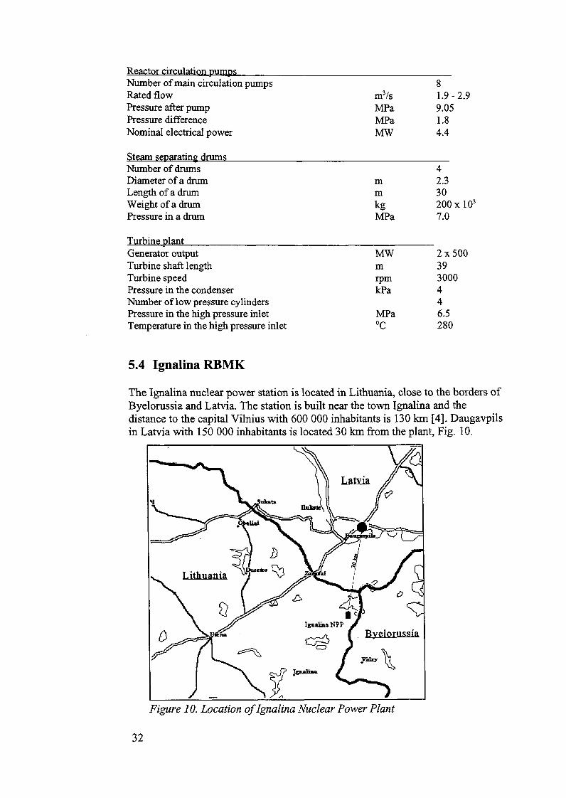
The Ignalina nuclear power station is located in Lithuania, close to the bordets ofByelorussia and Latvia. The station is built near the town Ignalina and thedistance to the capital Vilnius with 600 000 inhabitants is 130 km [4]. Daugavpilsin Latvia with 150 000 inhabitants is located 30 km from the plant, Fig. 10.
Figur e 10. Location of Ignalina Nuclear Power Plant
32

The plant has two units with graphite moderated pressure tube boiling waterreactors of similar type as the Leningrad Nuclear Power Plant (LNPP). TheIgnalina Nuclear Power Plant (INPP) and units 3 and 4 at LNPP represent thesecond generation of RBMK development, while units l and 2 at LNPP representthe first generation.
The electrical output of each unit at the Ignalina Nuclear Power Plant is1500 MW, but since the Chernobyl accident the allowable power of each unit hasbeen reduced to 1250 MWe. The first unit was taken in commercial operation in1984 and the second in 1987. The two units of the Ignalina Nuclear Power Plantcomprise the only construction of RBMK type of reactors with a designedelectrical output as high as 1500 MW.
The core dimensions of the Ignalina and Leningrad Nuclear Power Plants åre thesame as well as the amount of uranium in each core. However, Ignalina isdesigned to operate with 50 % higher power density in the core due to anincreased heat transfer obtained by a rotational water flow in the uppermost halfof the fuel assembly.
Table 7. Summary of design data for unit l ofthe Ignalina Nuclear Power Plant
Main data
Type RBMK-1500Thermal power 4800 MWCapacity, gross 1500 MWeCapacity, net 1440 MWe
Reactor core data
Core diameter 11.8 mCore height 7 mNumber of fuel channels 1661Numberof control rod channels 235Reflector cooling channels 156Square lattice pitch 0.25 mGraphite mass in the core 1700 tonMaximum graphite temperature 750 °C
Fuel data
Fuel material U02Fuel inventory 192tUFresh fuel enrichment 2.0 wt%Average linear heat rate 218 W/cmPeak linear heat rate 485 W/cmRods per fuel element 18Fuel pellet diameter 11.5 mm
33

Diameter of fuel rodFuel elements per fuel assemblyLength of fuel elementDiameter of fuel elementChannel outside diameterChannel materialAverage fuel bumupCladding materialCladding thicknessAbsorbing control rods, B4CEmergency rods, B4CRefuelling technique
Primary circuit data
Recirculation loopsPrimary pumpsSteam drum separatorsPrimary pressureTotal coolant flowFuel channel inlet temperatureFuel channel outlet temperatureFeed water flow rateFeed water temperatureMaximum steam content at core outlet
13.5 mm183.4 m79 mm88Zr/Nb21500 MWd/tUZr/l%Nb0.9 mm21124On-load
28470 bar11100 kg/s260 °C284 °C2305 kg/s190°C29%
Turbine plant general
TurbinesSteam inlet temperatureSpeedInlet turbine pressureInlet temperatureSteam flowMoisture content inletNumber of high pressure cylindersNumber of low pressure cylindersTurbine length
Generator general
Generator outputVoltageRotor coolingStator cooling
2280 °C3000 rpm65 bar280 °C2445 kg/s0.5%l440 m
800 MW24 kVhydrogenwater
34

5.5 Characteristic differences between BWR and RBMK reactors
The RBMKs could be considered as a kind of boiling water reactors but designedfrom totally different principles than the Western type of boiling water reactors.One of the main differences is the way the neutrons åre moderated. WesternBWRs åre normally water moderated whereas RBMKs åre graphite moderated.RBMK thus represents unique design features with a graphite moderator and avery large core and a large load of low enriched uranium fuel.
The graphite moderator of the RBMK reactor plays a significant role in definingthe characteristics of the reactivity feedback coefficients, and due to the large coresize, the core power distribution is unstable, with the fuel load comprising severallocal critical masses. These special design features produce unique neutronics andcomplex reactivity control requirements.
Among the important safety design differences between the Leningrad andIgnalina RBMKs and the Brunsbuttel and Krummel BWRs the following itemscan me mentioned:
• Moderator type
• Power density
• Size of core
• Void coefficient
• Control rods
• Refuelling technique
• Passive safety systems
• Number of safety systems
• Boron injection system
• Active safety systems
• Containment system
• Filter/scrubber system
The graphite moderator of the RBMK reactor is exposed to a special ageingeffect. Due to irradiation the graphite is accompanied by a creep or shrinkageeffect, which causes a closure of the gap between the fuel channels and thegraphite blocks. Thus, after about 15 years of operation the graphite blocks needto be bored out to enlarge the channel diameter - a very costly and complicatedprocess.
35

The differences in volumetric power densities between RBMK reactors andWestern BWRs åre due to the size of the core. The core volume of a RBMKreactor is about 10 times the volume of a Western BWR with the same thermalpower. The fuel specific power expressed as kW/kgU is about 22 for both type ofreactors, whereas the core power density is about 50 W/cm3 for Brunsbuttel andKrurnrnel and 5-7 W/cm3 for RBMK reactors.
The graphite moderator constitutes a large heat sink in case of a loss of coolantaccident. E.g. in case of failure of the decay heat removal system the heatcapacity of the graphite mass is assumed to accumulate most of the decay heat forat least 24 hours without leading to any fuel damage.
The coolant void reactivity coefficient of the RBMK reactor is positive under mostoperating conditions whereas this coefficient is negative for Western BWRreactors. The positive coefficient is due to the faet that the moderating effect ofthe water is relatively small since most of the moderation is caused by thegraphite. Thus a decrease of the coolant density by voiding is accompanied by adecrease in neutrons absorbed in the coolant and a corresponding increase inreactivity. In a Western BWR, the negative moderating effect of removing wateris always greater than the positive absorber effect, so that the void coefficient isnegative. The positive coolant void coefficient is supposed to have been animportant contributor to the Chernobyl accident. From a regulation point of viewit is desirable to have a negative void reactivity coefficient of small numericalvalue.
For most RBMK reactors the enrichment has been increased and additionalabsorbers have been installed in the core after the Chernobyl accident. In this waya less positive coolant void coefficient has been obtained because a smallerfraction of neutrons now is absorbed in the coolant, making the reactivity lesssensitive to coolant density changes.
One characteristic difference between the control rods of RBMK reactors andWestern BWRs is their direction of movement. The control rods of RBMKreactors åre inserted from the top of the core, opposite to Western BWRs wherecontrol rods åre inserted from the bottom. Thus, the RBMK way of movementutilizes gravity as a passive safety feature wheras the Western design utilizes theeffect of faster response due to higher power density in the bottom of the core.
The number of control rods, their design and velocity of insertion have beenchanged for RBMK reactors after the Chernobyl accident. Each RBMK reactorhas been equipped with 80 new absorber assemblies, which åre left permanentlyin the core. The design of the local emergency control rods has been changed byeliminating water columns in the lower part of the rods and including largerabsorbing sections, see Fig. 11, thus avoiding an initial positive reactivityinsertion during operation as was the case at Chernobyl. Further the insertion timeof the local emergency rods has been reduced from 18 to 12 seconds.
36

l 2
H Absorbing element
l 2
Graphite displacer %$£& Cooling water
Figure l J. Control rod positions at different levels in the core
A - rod o f original designB - rod of original design partly inserted into core to eliminate the possibility of insertion of positive
reactivityC - improved rod1 - rodwithdrawn2 - rod inserted
One special feature of the RBMK reactors is refuelling during power operation.The refuelling operation is remotely controlled, and the reactor hall is unoccupiedduring the operation. Normally two refuelling operations åre made each day atfull power and the whole operation takes about two hours.
At a Western BWR refuelling is carried out during the annual shut-down formaintenance and repair.
Both types of reactors åre provided with emergency core cooling systems, but theapplication of redundancy and diversity is more consistent in the Krummel andBrunsbuttel reactors than is the case for the Leningrad and Ignalina nuclear powerplants.
The Krummel and Brunsbuttel reactors åre provided with a secondary diverseshut-down system, that is a boron injection system, which is to be used in case ofa failure of the normal control rod shut-down system. The Leningrad and IgnalinaNPPs have no secondary shut-down system.
The lack of a pressure containment for the RBMK reactors is from a safety pointof view the most important design difference between Eastern and Westernboiling water reactors. The Ignalina Nuclear Power Plant and units 3 and 4 of theLeningrad Nuclear Power Plant åre provided with a confmement system, a so-called accident localization system. However, the design philosophy of thisconfmement is different from the Western philosophy. It is not a leaktightbuilding around the reactor but it is a building where the discharged steam andgas mixture in case of a main coolant pipe break is condensed by bubbling
37

through a condenser-pool, purified and released to the atmosphere after a certaindelay time, Fig. 12.
Figure 12. Accident localization system ofRBMK reactor
1 - Reactor tank2 - Steam separator compartment3 - Pump compartment4 - Compartment below reactor5 - Corridor6 - Rupture disc7 - Relief valve8- Water lock9 - Drainagel O - Relief pipes from the reactor tank11 - Thermoelement12 - Sprinkler13 - Bubbler14 - Bubblers water pool15 - Lower water pool16 - Upper water pool17 - Upper water tank18- Pressure measurement19 - Cold water for sprinklers20 - NA-service water21 - Cold water for bubblers pool22 - Emergency core cooling water line23 - Carbon filters24 - Ventilation stack25 - Valves and rupture discs (membrane)
38

The overpressure protection system of the reactor tank also discharges to thisaccident localization system in case of a rupture of a fuel channel pressure tube.The original design basis of the protection system was a break of a single pressuretube, but the relief capacity from the reactor tank volume has been increased, sothat it now can withstand simultaneous breaks of four fuel channels.
The units l and 2 at the Leningrad Nuclear Power Plant have no accidentlocalization system, so the condensing capacity and the delay time of possiblereleases åre smaller. According to the backfitting plans for units l and 2 they willbe provided with an accident localization system in 1995.
IAEA has stressed the necessity of increasing the relief capacity from the reactorspace, so plans åre underway to increase the number of allowable simultaneouspressure tube breaks to ten for all RBMK reactors. If the pressure in the tankspace exceeds the relief capacity, the upper biological shield will lift and a seriousaccident might occur.
The containments of the Brunsbuttel and Krummel BWRs åre designed towithstand a pressure of 5 bar and also capable to withstand a crash of an airplane.Furthermore, if relief of steam or gases to the atmosphere should be necessary itwill take place only after long delay times through filters and scrubbers.
39


6 Marine reactors
The humber of nuclear powered vessels and especially submarines operating ininternational waters is so large, that the authorities and the public åre showingincreased concern of the potential risk; some of these vessels åre also operatingnear the Nordic coasts. More than 400 of them åre military submarines, about 80of which åre continuosly present in the North Atlantic. In 1989 Russia had sixnuclear-propelled icebreakers and one combined icebraker-cargo ship inoperation, Table 8 [5].
Table 8. Nuclear powered vessels in use or in order (parenthesis) in 1989.
France
Russia
UK
USA
Total
Sub-marines
12 (4)
214 (16)
23 (3)
157 (12)
406 (35)
Aircraftcarriers
1 O)
(2)
5 (2)
6 (5)
Cruisers
2 (2)
9
11 (2)
Ice-Breakers
6
6
Cargo
1
1
Sum
13 (5)
224 (20)
23 (3)
171 (14)
431 (42)
The safety authorities and the public in the Nordic countries åre becomingincreasingly concemed about the potential risks involved, as evidenced by therecent Russian submarine accidents in the North Atlantic.
6.1 Nuclear propulsion plants
A typical layout of a propulsion plant with a pressurized water reactor is shown inBEACrOfl COMPARTMGNr Fig. 13.
PWMAflY CWCU1I SECONOARY CIRttMT
J TWW7TLE EtECTOCALMA1N PROPULSION MOrOfl
Figure 13. Layout of a dispersedPWR nuclear propulsion plant.
41

The primary circuit of the nuclear propulsion plant consists of the nuclear fuelcore, control rod systems, pressure tank, pressurizer and steam generators. Thesecondary circuit comprises steam turbines, steam condenser and auxiliarysystems. A mechanical clutch and gear system transfers the power to the propellershaft.
The design shown above is a so-called dispersed loop design in contrast to thedesign shown in Fig. 14, where the steam generators and main coolant pumps åreintegrated in the pressure tank.
Since weight and space requirements åre of great concern for submarines, theintegrated design is mostly applied in this case.
Primary circuit Secondary circuit
Control rods
Pressure vesseJ
Sieam generator
Primary pumps
Nuclear core
CearVal veHigh-prcssure turbine
low-pressure turbi
High prcssure
Cooting watef
Reactor
Degaserl
Low-pressure prc-heatcr Condcnsalc pump
Figur e 14. Layout ofan integrated nuclear propulsion plant
6.2 Nuclear powered submarines
It is hardly surprising that the first practical application of nuclear propulsion ofmaritime vessels was in submarines. The use of nuclear power permits thesubmarines to move submerged for almost any period of time.
The Russian type of submarines åre often provided with two nuclear propulsionplants of the PWR type, while the Western types rely on a single PWR plant.Most submarines åre equipped with containments as well as emergency corecooling systems.
The type of information needed for safety assessment of nuclear submarines isclassified and not available through the open literature. One has to rely on genericinformation relating to the design, operation and safety assessments of civiliannuclear power plants, land-based and marine-based. To some extent this might beadequate, but vital information on reactor fuel design and operation is lacking.
42

To perform a risk assessment of a sunken submarine the following informationwould be needed:
• General design, construction and layout of nuclear submarines
• Design and layout of nuclear plants
• Design, mechanical strength and function of all protective fuel barriers
• Vulnerability of these protective barriers to collisions or accidents, inparticular to shocks from explosive charges onboard
• Power level and operating history of the core of the nuclear plant prior todamage
According to the defence-in-depth principle the following four safety barriersexist:
• The first barrier is the fuel cladding. In the reactor core there may be morethan 10 000 pins or plates and if the cladding should crack the fissionproducts will be released to the primary system. The amount of releasedepends on fission product volatility and fuel temperature.
• The second barrier is the walls which contain the primary coolant underpressure i.e. the walls of the pressure vessel. It is believed that the pressurevessel itself can withstand considerable shocks, whereas the tubesconnecting the pressure vessel with steam generators, pressurizer, etc. årevulnerable. No information is available on how the primary system insubmarine plants is designed to resist external shocks. The choice between aloop and an integrated design is influenced by the system's ability to resistshocks.
• The third barrier is the containment structure, that is a tank which containsthe entire primary system. It can either be a "full pressure load" design withfull-scale blow-down of the coolant in the primary system or it can be a"pressure suppression system".
• The fourth barrier - the safety enclosure or the submarine hull - is intendedto prevent the release of radioactive substances to other parts of the vessel.The limits of the safety enclosure åre longitudinal and transverse bulkheadsof the reactor compartment and the hull.
Fig. 15 illustrates the defence-in-depth principle with the four barriers.
43

Tturd Barrier:Reactor Containmeni '
Fourth Barrier:Submarine Hul)
first Barrier:FuelCUdding
Second Barrier:Reactor Primary Circuit
Figure 15. The four physical barriers between the fissionproducts and the environment.
44

6.3 Civilian nuclear ships
Three countries have built and operated nuclear powered merchant ships, UnitedStates, Germany and Japan. The three ships were NS Savannah, NS Otto Hahn,and NS Mutsu. They were all supplied with pressurized water reactors withcluster type fuel elements containing slightly enriched UO2 and a containmenttank around the primary circuit. Data for the three ships åre listed in table 9 [6].
Table 9. Data for nuclear merchant ships
Typeofship
Start of construction
Initial criticality
Full power
Retired
Length, m
Beam, m
Depth, m
Dead weight, t
Cargo, t
Gross tonnage
Shaft horsepower
Service speed, kn
Gross thermal power, MW
Core diameter, cm
Core height, cm
Number of fuel elements
Lattice pitch, square, cm
Fuel enrichments, %
Core loading, kg U
Power density, kW/1
Average burnup, MWd/tU
Fuel materiale
Number of control rods
Number of coolant loops
Reactor pressure, bar
Savannah
Cargo + passenger
1958
1961
1962
1971
182
23.8
9400
15600
22000
20
76
157.6
167.6
32
24.7
4.4
7112
23
7300
UO2
21
2
123
Otto Hahn
Ore carrier
1963
1968
1968
1979
172
23.4
145
15000
14000
16900
10000
16
38
112
115
12+4
26.8
3.7
2622
33
7260
UO2
12
3
63.5
Mutsu
Special cargo
1968
1974
1990
1992
130
19.0
132
2430
2400
8200
10000
16.5
36
114.6
104
32
17.96
4.0
2440
33.5
5530
UO2
12
2
110
45

The first civilian nuclear ship in the world was the Soviet icebreaker NS Lenin.Construction started in 1956 and operation in late 1959. NS Lenin was providedwith 3 stem screws and the hull was divided into sections by 11 transversewaterproof bulk-heads.
Initially the icebreaker was supplied with 3 identical reactors designated OK-150,a pressurized water reactor chosen because it allows a compact design andbecause of the negative temperature coefficient of PWRs. The thermal power ofthe reactors was 90 MW.
According to Western intelligence reports NS Lenin experienced a nuclear relatedaccident around 1966-67. As a consequense of this accident, the original powerplant was removed and replaced by two KLT-40 plants, which also åre based onpressurized water reactors and have a thermal power of 135 MW. The same typeof plant has subsequently been installed in all later Russian icebreakers. The NSLenin icebreaker was retired in 1989.
KLT-40 is provided with emergency core cooling systems capable of supplyingwater to the primary system in case of a major leak and it also has a containment.
All Russian nuclear icebreakers åre operated by the Murmansk Artic ShippingCompany and the KLT-40 plants have been in operation for more than 110 000hours, corresponding to 125 operating years. The icebreakers have been able tooperate continuously for 400 days in the Artic with availability around 76-79 %and only one scram in average per year.
The construction of a Russian icebreaking transport/container ship, NSSevmorput started in 1984 and the ship was finished in 1988. A substantialamount of information about this ship is available since a Russian safety reporthas been published in English.
NS Sevmorput has a high strength steel containment with a pressure suppressionsystem, designed to cope with the consequences of a main coolant pipe break.Should the ship sink, a pressure equalizer system will flood the containment untilthe pressure is the same on both sides of the containment wall.
46

7 Concluding remarks
Design and safety features for eight nuclear power plant sites, neighbouring theNordic countries within 100-450 km, have been collected and systematized duringthe SIK-3 project. The project has provided improved knowledge of especially theEastern type of reactors, for the benefit of the nuclear authorities within theNordic countries.
The uniform presentation of the data of each plant is designed to facilitate easyaccess to the information when needed. It should be stressed, that an evahiation ofthe safety condition of a particular plant on basis of the reports is beyond thescope of the project. The reports only state the facts and special safety features ofeach reactor type, providing quick information in emergency situations.
When the project was initiated scepticism was present among some of theparticipants as to the usefulness of its outcome. However, this doubt disappearedas assistance to the Eastern countries from the West was intensified.
As a matter of faet, the reports on Ignalina and Leningrad nuclear power plantshave been utilized by EBRD, the European Bank for Reconstruction andDevelopment, in connection with establishing an assistance program for theRBMK reactors in the former Soviet Union.
The contact net among the Nordic nuclear authorities has also been improvedduring the project, useful if a nuclear accident involving Nordic countries shouldoccur.
A contact net between the Nordic nuclear authorities and the Eastern nuclearpower plant operators has also been established and bilateral agreements will helpto sustain and improve this net. In general the hospitality met from the Easternnuclear power plant operators was better than from most of the Westernoperators.
However, improvements and backfitting of the Eastern nuclear power plants takeplace at a fast rate, so an updating of the reports will be needed within few years.Also the rather sparse treatment of the Stade and Brokdorf nuclear power plantsought to be improved in the future.
Finally, the project has made accessible some of the design characteristics ofnuclear powered ships operating in the seas close to the Nordic countries.
47


8 References
1. NU 1975:35-NARS, Nordic Working Group on Reactor SafetyRecommendations
2. SIK-3. l Description of Greifswald Nuclear Power Plant I-VIII.Ølgaard, P.L. andNonbøl, E. (1991)
3. SIK-3.2 Description of Leningrad Nuclear Power Plant I-IV.Ollikkala, H. and Eurasto, T. (1992)
4. SIK-3.3 Description of Ignalina Nuclear Power Plant I-II.Bento, Jean P. (1992)
5. SIK-3.4. l Description of Nuclear Powered Vessels.Wethe, P.L (1992)
6. SIK-3.4.2 Description of Nuclear Powered Civilian Ships.Ølgaard, P.L. (1992)
7. SIK-3.4.3 Nuclear Ship Accidents - Description and AnalysisØlgaard, P.L. (1993)
8. SIK-3.4.4 Decommissioning of Naval Nuclear ShipsØlgaard, P.L. (1993)
9. SIK-3.5 Description of Kola Nuclear Power PlantStokke, E. (1993)
10. SIK-3.6 Description of Brunsbiittel Nuclear Power Plant.Olofsson, B.G. (1992)
11. SIK-3.7 Description of Krummel Nuclear Power Plant.Olofsson, B.G. (1992)
12. SIK-3.8 Description of Brokdorf Nuclear Power PlantSiljestrom, A. (1993)
13. SIK-3.9 Description of Stade Nuclear Power PlantSiljestrom, A. (1993)
14. TemaNord 1994:544-NKS, Nordic Studies in Reactor SafetyPershagen, B.
49


Appendix l : Disposition of the reports
1. Introduction
2. Summary of design data
2.1 Comparisons with similar reactor types
3. Site and region
3. l Selection of the site3.1.1 Geographical location
3.2 Description of the site3.2.1 Site use and topography3.2.2 Geology3.2.3 Plant personnel and others working or living on the site
4. Safety criteria
4. l Safety related design criteria
4.2 Classification of structures, systems and components
4.3 Conditions of design
4.4 Missile protection
4.5 Fire protection criteria
5. Technical description and design evaluation
5. l Plant arrangement
5.2 Building and structures
5.3 Reactor core and other reactor vessel internals5.3.1 Mechanical design5.3.2 Nuclear design5.3.3 Thermal and hydraulic design
5.4 Reactivity control systems
5.5 Reactor main coolant system
51

5.5.1 System information5.5.2 Reactor vessel5.5.3 Reactor coolant piping5.5.4 Reactor coolant pumps5.5.5 Steam generators5.5.6 Pressuriser (PWR)5.5.7 Pressuriser relief tank (PWR)5.5.8 Safety and relief valve systems5.5.9 Valves
5.6 Residual heat removal systems
5.7 Emergency core cooling systems
5.8 Containment systems5.8.1 Overall system information5.8.2 Containment structure5.8.3 Containment penetrations5.8.4 Containment isolation system5.8.5 Pressure reducing and heat removal systems5.8.6 Containment air cleanup system5.8.7 Containment gas control system5.8.8 Secondary Containment5.8.9 Filtered Containment venting system
5.9 Steam and power conversion systems5.9.1 Overall system information5.9.2 Turbine-generator5.9.3 Main steam supply system5.9.4 Main condensers and evacuation system5.9.5 Turbine gland sealing system5.9.6 Turbine bypass system5.9.7 Condenser cooling system5.9.8 Condensate and feed water system5.9.9 Condensate cleanup system5.9.10 Steam generator blowdown system (PWR)5.9.11 Safety and relief valves (PWR)5.9.12 Other turbine auxiliary systems
5.10 Fuel and component handling and storage systems5.10.1 New fuel storage5.10.2 Spent fuel storage5.10.3 Radioactive component storage5.10.4 Handling and inspection systems
5.11 Radioactive waste systems5.11.1 Liquid waste systems5.11.2 Gaseous waste systems5.11.3 Solid waste systems
52

5.12 Control and instrumentation systems5.12.1 Overall system information5.12.2 Common equipment5.12.3 Protection system5.12.4 Regulating system5.12.5 Instrumentation system
5.13 Electrical power systems5.13.1 Main transformer and connected equipment5.13.2 Network interconnections5.13.3 Plant distribution system5.13.4 Standby power supply
5.14 Other sy stems
6. Fire protection
6.1 Buildings, layout and materials
6.2 Fire-fighting equipment
6.3 Organisation
6.4 Fire-fighting
7. Plant performance during normal operation
7. l Phases of normal operation
7.2 Joint functioning of groups of systems
7.3 Summary of releases of radioactive material from the plant
7.4 Plant statistics
8. Accident analyses
8.1 General description of safety systems
8.2 Malfunctions in different systems8.2.1 Inside the reactor8.2.2 Outside the reactor
8.3 External event analysis
53

9. Radiation protection
9.1 Basic radiation protection criteria and deri ved working rules9.1.1 Dose limits9.1.2 Recorded history of exposure9.1.3 Radiation protection service
9.2 Shielding
9.3 Radiation9.3.1 Radiation level s9.3.2 Radiation monitoring
9.4 Contamination9.4.1 Radiation levels9.4.2 Contamination monitoring
9.5 Monitoring systems and action levels for radioactive releases to theenvironment
9.5.1 Monitoring of releases to the atmosphere9.5.2 Monitoring of releases to water
10. Offsite dose assessment
10.1 Releases under operating conditions10.1.1 Summary of calculated releases10.1.2 Contamination of the environment10.1.3 Radiation doses
10.2 Releases under hazardous conditions10.2. l Summary of calculated releases10.2.2 Contamination of the environment10.2.3 Radiation doses
10.3 Influence of emergency measures
10.4 Environmental surveillance
11. Planning, organisation and administrative control
11.1 Operation11.1.1 Operating programme11.1.2 Organisation11.1.3 Personnel qualifications, educations11.1.4 Training programme11.1.5 Operating procedures, instructions and orders
54

11.1.6 Logs and records11.1.7 Review and audit11.1.8 Reports to authorities
12. Organisation of the authorities
12.1 Overall organisation
12.2 Local organisation
13. Probabilistic safety assessment
55


Appendix 2 : Rules of distribution for SIK-3 reports
The SIK-3 reports about reactors in neighbouring countries may containinformation that was obtained confidentially. This implies some restrictions ontheir distribution.
The reports åre printed in a limited number - preferably in the normal publicationseries of the authors' institution, but with a NKS cover or front page. Limitationsconcerning distribution åre described in the introductory remarks of each report,taking into account the following rules:
• The reports åre available for all participants within the NKS programaccording to an approved distribution list
• The reports åre mainly for use of reactor safety authorities in the Nordiccountries and for their national advisory bodies and contributingutilities.
• Provided that the nuclear plant organization described in the report hasscrutinized the report, it may under certain circumstances be exchangedwith authorities or utilities in third countries for their own restricteduse. The same possibility exists if further distribution is desired, e.g. tointernational organizations.
• Such exchanges must be initiated by one of the Nordic reactor safetyauthorities, and it can only take place after consultation with thecorresponding authorities in the other Nordic countries.
57

Design and Safety Features of Nuclear Reactors Neighbouring the Nordic Countries
There are several nuclear power plants in operation dose to the borders of the Nordic countrie, and in the sea surrounding the Nordic region there is a consideable number of nuclear submarines and other vessels, The authorities responsible for nuclear safety need to have easy access to information about all t h e e reactors. The present report contains an overview of individual reports about reactors neighbouring the Nordic countries, produced in a joint Nordic project of the NKS-programme.
The Nordic Committee for Nuclear Safety Research - NKS organizes pluriannual joint research programmes. The aim is to achieve a better understanding in the Nordic countries of the factors influencing the safety of nuclear installations. The progrmme also permits involvement in new developments in nuclear safety, radiation protection, and emergency provisions. The three first programmes, from 1977 to 1989, were partly financed by the Nordic CounciI of Ministers.
The 1990 - 93 Programme Comprises four areas: * Emergency preparedness (The BER-Programme) * Waste and decommissioning (The KAN-Programme) * Radioecology (The RAD-Programme) * Reactor safety (The SIK-Programme) The programme is managed - and financed - by a consortium comprising the Dan-_ Emergency Management Agency, the Finnish Ministry of Trade and Industry, Icelands's National Institute of Radiation Protection, the Norwegian Radiation Protection Authority, and the Swedish Nuclear Power Inspectorate. Additional financing is offered by the IVO and TVO power companies, Finland, as well as by the following Swedish organizations: KSU, OKG, SKN, SRV, Vattenfall, Sydkraft, SKB.
ADDITIONAL INFORMATION is available from the NKS secretary general, POB 49, DK-4000 Roskilde, fax I+45) 46322206
@ The Nordic Council of Ministers ISBh 92 9120 521 I ISSh 0906-6692