Embed Size (px)
Citation preview

Verification Report
BASF S.E.
2nd Periodic Verification of the Registered JI Track 1 Project
UNFCCC DE1000024
“Catalytic Reduction of N2O inside the Ammonia Burners of the BASF Nitric Acid Plant in Ludwigshafen”
Monitoring period #2: 01-10-2009 to 28-02-2011
Report No. 600500705
27 December 2011
TÜV SÜD Industrie Service GmbH Carbon Management Service
Westendstrasse 199 - 80686 Munich - GERMANY

PERIODIC VERIFICATION “Catalytic Reduction of N2O inside the Ammonia Burners of the BASF Nitric Acid Plant in Ludwigshafen” Page 1 of 25
Report No. Date of first issue Version No.:
Revision date No. of pages
600500705 17-08-2011 05 27-12-2011 25
Subject: Second Periodic Verification
Executing Operational Unit: TÜV SÜD Industrie Service GmbH, Carbon Management Service Westendstrasse 199 - 80686 Munich, Federal Republic of Germany
Project Participant (client): BASF SE E-CAA/SN - M211 67056 Ludwigshafen, Germany
Registration number / Project Title DE1000024 / Project: “Catalytic Reduction of N2O inside the Ammonia Burners of the BASF Nitric Acid Plant in Ludwigshafen”
Monitoring period: 01-10-2009 to 28-02-2011
First Monitoring Report (version/date) Version 01 / 29-04-2011
Final Monitoring Report (version/date) Version 03 / 10-11-2011
PERIODIC VERIFICATION “Catalytic Reduction of N2O inside the Ammonia Burners of the BASF Nitric Acid Plant in Ludwigshafen” Page 2 of 25
Summary: The certification body “Climate and Energy” of TÜV SÜD Industrie Service GmbH has been ordered by BASF S.E. to carry out the subsequent periodic verification of the registered JI Track-1 project “Catalytic Reduction of N2O inside the Ammonia Burners of the BASF Nitric Acid Plant in Ludwigshafen”. The verification is based on requirements of the UN Framework Convention on Climate Change (UNFCCC) and the host country specific requirements. In this context, the specific guidance from the Designated Focal Point (host country) in his responsibility for the approval of JI track 1 projects, relevant provisions set by the Marrakech Accords, the Kyoto Protocol and the JI-SC (Supervisory Committee) for JI Track-2 projects have been taken into consideration. The verification of this JI project has been performed by document review, interviews by e-mail and inspection on-site. The verifier confirms that the project is implemented as planned and described in determined project design document. Installed equipment being essential for generating emission reduction runs reliably and is calibrated appropriately. The monitoring system is in place and the project does generate GHG emission reductions. The verifier confirms also that the monitoring plan of the project activity is in accordance with the applied methodology. The management of BASF in cooperation with project consultant FutureCamp Climate GmbH is responsible for the preparation of the GHG emissions data and the reported GHG emissions reductions on the basis set out within the final approved and registered PDD dated 06 June 2008 and the revised Monitoring Plan version 05 dated 10 June 2011, submitted with this verification. The verifier confirms that the adjustments and improvements in the revision of the Monitoring Plan enhance the level of accuracy and completeness and quality of the monitoring plan. The revised Monitoring Plan is subject to the approval by the German DFP- DEHSt. The verifier can confirm that the GHG emission reduction for the whole monitoring period is calculated without material misstatements. Our opinion relates to the project’s GHG emissions and resulting GHG emissions reductions reported and related to the valid project baseline and monitoring, and further associated documents. The indicated emission reductions calculated for this period are in a reasonable range to the values indicated in the registered PDD. Based on the information received and evaluated we confirm the following statement:
Reporting period: from 01 October 2009 to 28 February 2011
Verified emission in the above reporting period:

PERIODIC VERIFICATION “Catalytic Reduction of N2O inside the Ammonia Burners of the BASF Nitric Acid Plant in Ludwigshafen” Page 3 of 25
Start and End date
Achieved emission reductions
EF baseline=2.5 kgN2O/tHNO3 EF baseline=4.5 kgN2O/tHNO3
2009/10/01 – 2009/12/31
37,053 t CO2 equivalents 112,798 t CO2 equivalents
2010/01/01 – 2010/09/30
122,261 t CO2 equivalents 361,332 t CO2 equivalents
2010/10/01 – 2010/12/31
45,037 t CO2 equivalents 45,037 t CO2 equivalents
2011/01/01 – 2011/02/28
27,085 t CO2 equivalents 27,085 t CO2 equivalents
Total 231,436 t CO2 equivalents 546,252 t CO2 equivalents
Total 2009 37,053 t CO2 equivalents 112,798 t CO2 equivalents
Total 2010 167,298 t CO2 equivalents 406,369 t CO2 equivalents
Total 2011 until the end of the 2nd monitoring period
27,085 t CO2 equivalents 27,085 t CO2 equivalents
Assessment Team Leader: Olena Maslova Assessment Team Members: Martin Hammer
Technical Reviewer: Thomas Kleiser Certification Body responsible: Thomas Kleiser

PERIODIC VERIFICATION “Catalytic Reduction of N2O inside the Ammonia Burners of the BASF Nitric Acid Plant in Ludwigshafen” Page 4 of 25
Abbreviations ADS Adipic Acid AIE Accredited Independent Entity AMS Automated Monitoring System BASF BASF SE E-CAA/SN - M211 67056 Ludwigshafen, Germany CAR Corrective Action Request CDM Clean Development Mechanism CER Certified Emission Reduction CMP Conference of the Parties serving as the Meeting of the Parties to the Kyoto
Protocol CO2e Carbon dioxide equivalent CR / CL Clarification Request DEHSt DFP for JI/CDM project implementation in the Federal Republic of Germany
(Deutsche Emissionshandelsstelle, URL: www.dehst.de) DFP Designated Focal Point DK Absorption Process Train DVM Determination and Verification manual EF Emission Factor EIA / EA Environmental Impact Assessment / Environmental Assessment ER Emission Reduction FAR Forward Action Request GHG Greenhouse Gas(es) GWP Global Warming Potential IPCC Intergovernmental Panel on Climate Change IRL Information Reference List JI Joint Implementation JISC JI Supervisory Committee KP Kyoto Protocol LoA Letter of Approval LP Low Pressure MP Monitoring Plan MR Monitoring Report N/A Not applicable NAP Nitric Acid Production PDD Project Design Document PP Project Participant ProMechG German JI related legislative act / Federal Law, Projekt-Mechanismen-Gesetz TÜV SÜD TÜV SÜD Industrie Service GmbH UNFCCC United Nations Framework Convention on Climate Change VVM Validation and Verification Manual

PERIODIC VERIFICATION “Catalytic Reduction of N2O inside the Ammonia Burners of the BASF Nitric Acid Plant in Ludwigshafen” Page 5 of 25
Main Documents (referred to in this report) Methodology (name / version) Project specific based mainly on AM0034, Version 3 Scope 05 Technical Area 5.1, 5.2 Registered PDD: Date 06-06-2008 Revised Monitoring Plan: Version 05, date 10-06-2011, Date of approval: with this
verification Version Date Published Monitoring Report 01 29-04-2011 Revised Monitoring Report 03 10-11-2011 Project documentation link: UNFCCC:
http://ji.unfccc.int/JIITLProject/ DB/FLC5CI6TQIQ7SWZ35RD8S4VNF66AS5/details DEHSt: https://www.jicdm.dehst.de/promechg/pages/project1.aspx

PERIODIC VERIFICATION “Catalytic Reduction of N2O inside the Ammonia Burners of the BASF Nitric Acid Plant in Ludwigshafen” Page 6 of 25
Table of Contents Page 1 Introduction ........................................................................................................................... 7
1.1 Objective ........................................................................................................................ 7 1.2 Scope ............................................................................................................................. 8 1.3 GHG Project Description ................................................................................................ 8
2 Methodology ........................................................................................................................ 10 2.1 Verification Process ..................................................................................................... 10 2.2 Verification Team ......................................................................................................... 10 2.3 Review of Documents .................................................................................................. 11 2.4 On-site Assessment and follow-up Interviews ............................................................. 12 2.5 Quality of Evidence to Determine Emission Reductions .............................................. 13 2.6 Resolution of Clarification and Corrective and Forward Action Requests ................... 13 2.7 Internal Quality Control ................................................................................................ 13
3 Verification Results ............................................................................................................. 15 3.1 FARs from Validation / Previous Verification ............................................................... 15 3.2 Project Implementation in accordance with the registered Project Design Document . 15 3.3 Compliance of the Monitoring Plan with the Monitoring Methodology ......................... 16 3.4 Compliance of the Monitoring with the Monitoring Plan ............................................... 17 3.5 Assessment of Data and Calculation of Greenhouse Gas Emission Reductions ........ 17
4 Summary of Findings .......................................................................................................... 18 5 Verification Statement ......................................................................................................... 24 Annex 1: Verification Protocol Annex 2: Information Reference List
PERIODIC VERIFICATION “Catalytic Reduction of N2O inside the Ammonia Burners of the BASF Nitric Acid Plant in Ludwigshafen” Page 7 of 25
1 INTRODUCTION
1.1 Objective BASF S.E. has commissioned an independent verification by TÜV SÜD Industrie Service GmbH (TÜV SÜD) of its registered JI Track-1 project: “Catalytic Reduction of N2O inside the Ammonia Burners of the BASF Nitric Acid Plant in Ludwigshafen”.
Verification is the periodic independent review and ex-post determination by the Accredited Independent Entity (AIE) of the monitored reductions in GHG emissions during the defined verification period.
Periodic Verification:
The objective of the periodic verification is to verify that actual monitoring systems and procedures are in compliance with the monitoring systems and procedures described in the monitoring plan for the respective period. Furthermore, the periodic verification evaluates the GHG emission reduction data and expresses a conclusion with a high, but not absolute, level of assurance about whether the reported GHG emission reduction data is free of material misstatements and verifies that the reported GHG emission data is sufficiently supported by evidence, i.e. monitoring records. The verification shall consider both quantitative and qualitative information on emission reductions. Quantitative data comprises the monitoring reports submitted to the verifier by the project entity. Qualitative data comprises information on internal management controls, calculation procedures, and procedures for transfer, frequency of emissions reports, review and internal audit of calculations/data transfers.
The verification work ensures that the project activity is assessed against all applicable JI Track-1 requirements in the host country as specified by the Designated Focal Point (DFP) for JI/CDM project implementation in Federal Republic of Germany. The JI requirements as reference include also the JI modalities and procedures and subsequent decisions by the COP/MOP and documents released by the JI-SC and available on the UNFCCC JI website http://ji.unfccc.int/index.html.
The objective of the verification work ensures that the project activity complies with the requirements as specified in the appendix B of the JI guidelines on the aforementioned UNFCCC JI website http://unfccc.int/resource/docs/2005/cmp1/eng/08a02.pdf#page=2. These guidelines are considered valid for JI Track-2 as also for JI Track-1. According to this assessment TÜV SÜD should:
Ensure that the project activity has been implemented and operated as per the registered PDD and that all physical features (technology, project equipment, monitoring and metering equipment) of the project are in place;
Ensure that the published MR and other supporting documents provided are complete and verifiable and in accordance with applicable JI Track-1 requirements in the host country;
Ensure that actual monitoring systems and procedures comply with the monitoring systems and procedures described in the monitoring plan and the applicable approved methodology;
Evaluate the data recorded and stored as per the methodology of approved PDD.

PERIODIC VERIFICATION “Catalytic Reduction of N2O inside the Ammonia Burners of the BASF Nitric Acid Plant in Ludwigshafen” Page 8 of 25
Evaluate the GHG emission reduction data and express a conclusion about whether the reported GHG emission reduction data is verifiable and sufficiently supported by evidence, i.e. monitoring records.
1.2 Scope Verification scope is defined as an independent and objective review and ex-post determination by the AIE of the monitored reductions in GHG emissions. The verification is based on the submitted Monitoring Report and the registered Project Design Documents and revised Monitoring Plan, submitted together with the 2nd MR. Determination Process and Final Approval
The determination of the project was carried out in 2008. The results of the determination were documented by TÜV SÜD in the Determination Report No. 1106682, dated 9 June 2008. This final Determination Report indicates no remaining issues with relevance for the subsequent verifications.
Following the relevant requirements of Article 6 of the Kyoto Protocol and the JI guidelines (refer to Appendix B of the JI guidelines, §§30-45 and to the national German regulations and procedures) project participant has applied a project specific approach. The principles of accuracy and completness, relevance, reliability and credibility were combined with a conservative approach to establish a traceable and transparent verification opinion.
Past to receipt of the Monitoring Report referred to the para. 36 of the JI guidelines, a verification of the reductions in anthropogenic emissions by sources of greenhouse gases reported by project participants (PPs) in accordance with appendix B of the JI guidelines has been made showing that those reductions were monitored and calculated in accordance with para. 33 of the JI guidelines.
The project was finally approved by the Designated Focal Point (DFP) for JI/CDM project implementation in the Federal Republic of Germany (DEHSt) in December 2008 (Date of LoA: 8 December 2008) and the Swedish DFP- Swedisch Energy Agency- in August 2010 (Date of LoA: 24 August 2010) and has the reference number DE-1000024. Verification process
The verification shall consider both quantitative and qualitative information on emission reductions. Quantitative data comprises the monitoring reports submitted to the AIE by the project entity. Qualitative data comprises information on internal management controls, calculation procedures, and procedures for transfer, frequency of emissions reports, review and internal audit of calculations/data transfers.
The verification is not meant to provide any consultancy towards the client. However, stated requests for clarifications and/or corrective actions as well as so-called forward action requests may provide input for improvement of the monitoring activities.
1.3 GHG Project Description
BASF operates a nitric acid production plant at the integrated production site in Ludwigshafen, Germany. The nitric acid plant is a complex network of 10 oxidation reactors feeding the NOx gas into the ring line which then distributes the gas stream to high pressure and low pressure absorption process trains. Due to the certain overlapping between the nitric acid plant and the neighboring adipic acid plant (where a separate JI project is taking place) in the context of the off gas treatment, there is a strict separation of emissions out of the different process trains.

PERIODIC VERIFICATION “Catalytic Reduction of N2O inside the Ammonia Burners of the BASF Nitric Acid Plant in Ludwigshafen” Page 9 of 25
Hence the project boundary of this particular project includes the emissions from the DK 2 to DK 5, except the periods when adipic acid off gas is lead over a process train (is counted in another ADS JI project), and emissions from the low pressure (LP) train, at which the monitored emissions are considered as project emissions in this particular project, and as leakage emissions of the adipic acid project (another JI project). The operating situation is monitored by the position of respective valves regulating the adipic acid off gas flow.
Nitric acid production exists in Ludwigshafen since 1928, with the current installation and capacity existing since 1978 (the overall approved plant capacity of 950 000 tHNO3/yr includes 850 000 tHNO3/yr from the nitric acid production and 100 000 tHNO3 equivalent/yr from the sodium nitrite production; the capacity of DK 1 production train of 170 000 tHNO3/yr is deducted, resulting in a production cap of 780 000 tHNO3/yr).
Nitric acid is used for the production of fertilizer, adipic acid and isocyanate in BASF facilities at the production site in Ludwigshafen and partly sold to other BASF sites as well as to third parties. Another product of the nitric acid plant in Ludwigshafen is sodium nitrite, which is used for food additives, precursor for dyes, fibres, pharma, rubber and crop protection. As described in the registered PDD, the sodium nitrite stems from the same ammonia oxidation reaction as nitric acid and can be calculated as 100% nitric acid equivalent; hence it is completely included into the project and subsumed under nitric acid production. As a by-product of the nitric acid production process, nitrous oxide (N2O) is generated and is emitted in the waste gas stream.
The selective N2O abatement catalyst is installed right below the platinum gauze in the ammonia oxidation reactors within the project boundary as a secondary N2O abatement measure. With this measure, emissions of the potent greenhouse gas N2O from the nitric acid production are reduced.
At the site the ammonia oxidation reactors have been successively equipped with the baskets and N2O catalyst over the period from the end of May 2008 to the end of February 2009. Now all ten oxidation reactors within the project boundary were equipped with the N2O decomposition catalyst and operate continuously.

PERIODIC VERIFICATION “Catalytic Reduction of N2O inside the Ammonia Burners of the BASF Nitric Acid Plant in Ludwigshafen” Page 10 of 25
2 METHODOLOGY
2.1 Verification Process
The verification process is based on the approach depicted in JI guidelines and, in particular, refer to the Guidance on Criteria for baseline setting and monitoring, chapter C. – Guidance on monitoring. Accordingly relevant requirements as set by the JI-SC for JI Track-2 are applied for JI Track-1 as long as there are no further host country requirements existing (and indicated in the national regulations and procedures) specifically for JI Track 1 projects. Following the good monitoring practice and its reporting, the approved Validation and Verification Manual and approved Joint Implementation Determination and Verification Manual (DVM) was also taken into consideration.
Standard auditing techniques have been adopted. The means of verification for the fulfilment of the requirements and reporting are as per the VVM and analogue as per the DVM. Thus, compliance with JI relevant guidance is ensured, too.
The work starts with a contract review and the appointment of the TÜV SÜD assessment team covering the technical scope(s) and area(s) as well as project activity and relevant host country experience for evaluating of this JI project activity. The principles of consistency and transparency, impartiality, independency and safeguarding against conflicts of interest and confidentiality were considered by the TÜV SÜD Certification Body (CB) and the management of the departement before accepting the verification contract.
Once the monitoring report is published on TÜV SÜD publication platform in internet “netinform” (as it is the matter of JI Track-1 project) and also at the webpage of the designated German Focal Point "DEHSt", the TÜV SÜD assessment team carries out a desk review, an on-site inspection, follow-up actions, resolution of issues identified and prepares a verification report. The verification report and other supporting documents then undergo an internal quality control by the TÜV SÜD Certification Body before its submission to the DFP (host country) for the final approval.
In order to ensure transparency, assumptions are clearly and explicitly stated, audit evidences and further background material are clearly referenced in Annex 2 of this report. Project and methodology-specific checklists and a customised protocol have been developed for the project. The protocol shows criteria (requirements) in a transparent manner, the discussion of each criterion by the assessment team and results of the subsequent verification.
The verification protocol (Annex 1) serves the following purposes:
It organizes, details and clarifies the requirements a JI project is expected to meet;
It ensures a transparent verification process where the verifier will document how a particular requirement has been proved and the conclusion provided by the verifiying team.
The findings are the essential part of this verification report, which are summarized in Annex 1 of the verification protocol.
2.2 Verification Team
According to the technical scopes and experiences in the sectoral or national business environment TÜV SÜD has composed a project team in accordance with the appointment rules of the TÜV SÜD certification body “climate and energy”. The composition of an assessment team has to be approved by the Certification Body (CB) ensuring that the required skills are
PERIODIC VERIFICATION “Catalytic Reduction of N2O inside the Ammonia Burners of the BASF Nitric Acid Plant in Ludwigshafen” Page 11 of 25
covered by the team. The TÜV SÜD CB operates four qualification levels for team members that are assigned by formal appointment rules:
Assessment Team Leader (ATL) Greenhouse Gas Verifier, Determiner (GHG-Verifier, GHG-Determiner) Greenhouse Gas Auditor Trainee (T) Experts (E)
It is required that the sectoral scope and technical area - both are linked to the methodology - has to be covered by the assessment team. The verification team was consisting of the following members:
Name Qualification Coverage of scope
Coverage of technical area
Host country experience
Olena Maslova ATL Martin Hammer GHG-Verifier
Olena Maslova is assessment team leader and GHG auditor (Determiner/Validator/Verifier) in the “Carbon Management Service” department of TÜV SÜD Industrie Service GmbH in Munich, Germany. She is chemical engineer and focal point for climate change projects in Eastern Europe. Due to her further master degree at the university of applied science in the Federal Republic of Germany she is also familiar with Germany’s current environmental legislation. Olena Maslova is specializing in the assessment of CDM / JI projects in the sector of chemical industries and waste handling and disposal.
Martin Hammer is environmental and mechanical engineer and is working as GHG Determiner/Validator/Verifier with a special focus on the scope “Industrial Gases” at the Carbon Management Service Department of TUEV Sued Industry Service GmbH in Munich, Germany. He has more than six years experience in JI/CDM projects with special focus on industrial gases. Additionally he gained extensive experience in renewable energies due to working on various consulting projects (wind, hydro, biomass, biogas, geothermal) and due to working as operator of a small hydro power plant in Austria.
Technical Reviewer: Thomas Kleiser.
2.3 Review of Documents
The monitoring report submitted by the Client and additional background documents related to the project performance have been reviewed.
The published Monitoring Report was assessed based on the registered PDD, the applied methodology and revised monitoring plan. These documents are listed in the presented section “Main Documents (referred to in this report)”, page 4. The main purpose of the assessment conducted was to verify the completeness and correctness of the data and the information presented in the monitoring report.
Monitoring Plan
Even though the Monitoring Plan has already been revised and approved by DEHST with the issuance of the ERU for the first monitoring period, several adjustments and improvements were necessary also in the second monitoring period to increase its transparency due to the complex

PERIODIC VERIFICATION “Catalytic Reduction of N2O inside the Ammonia Burners of the BASF Nitric Acid Plant in Ludwigshafen” Page 12 of 25
design of the nitric acid plant. Thus a revised MP has been submitted to the audit team for review at this verification. The history of revisions is transparently presented in chapter 1 of the revised MP. The main issues of this MP revision are described in detail in chapter 3.3 of this report.
The revisions of the Monitoring Plan version 05 were assessed with special awareness. Thus it is confirmed that they enhance the level of accuracy and completeness and quality of the monitoring plan.
Monitoring Report
The compliance check of the monitoring report with respect to the revised monitoring plan and the applied methodology was carried out. Particular attention was paid to the frequency of measurements, the quality of metering equipment including calibration requirements, and the quality assurance and quality control procedures. In addition, the evaluation of data management and the quality assurance and quality control system was carried out in the context of their influence on the generation and reporting of emission reductions.
Moreover, a detailed review of the project specific Software-Tool (based on MS-Excel) integrating the following data streams:
DURAG EMS system – HNO3 project - N2O emission monitoring in nitric acid tail gas - parameters P1, P2, P4, P6, P7, B3 and PI/ electronic log book for P.9
PI/electronic log book for P10 DURAG EMS system/ SAP/ PI/ electronic log book – nitric acid production monitoring
report parameters P5 and B2.
has been carried out on-site. All key parameters had been focused with special awareness. All automatic raw data entry and a proper use of correct default data from external data sources had been proved.
The list of references and further documents reviewed within the verification is attached as Annex 2 to this report.
2.4 On-site Assessment and follow-up Interviews
Verification of emission reductions of the monitoring period was done from 12-05-2011 to 13-05-2011 where TÜV SÜD performed a physical site inspection and on-site interviews with project stakeholders to:
confirm the implementation and operation of the project,
review the data flow for generating, aggregating and reporting the monitoring parameters,
confirm the correct implementation of procedures for operations and data collection,
cross-check the information provided in the MR documentation with other sources,
check the monitoring equipment against the requirements of the PDD and the approved methodology, including calibrations, maintenance, etc.,
review the calculations and assumptions used to obtain the GHG data and ER,
indentify whether the quality control and quality assurance procedures are in place to prevent or correct errors or omissions in the reported parameters.
A list of the persons interviewed during this verification activity is included in annex 2.

PERIODIC VERIFICATION “Catalytic Reduction of N2O inside the Ammonia Burners of the BASF Nitric Acid Plant in Ludwigshafen” Page 13 of 25
2.5 Quality of Evidence to Determine Emission Reductions
Among several evidence items submitted, the following relevant and reliable evidence material have been used by the audit team during the verification process:
Data from DURAG EMS system (IRL 3)
Excel based NAP calculation tools (IRL 3)
Nitric acid production records from PI and SAP (IRL 8)
Software tool based on MS-Excel spreadsheets with the aggregated original data (from DURAG and SAP) (IRL 3)
Calibration certificates, operating instructions and maintenance list (IRL 5-7)
Sufficient evidence covering the entire verification period in the required frequency is available to validate the figures stated in the final MR. The source of the evidence will be discussed in chapter 3 of this report. Specific cross-checks have been done in cases that further sources were available. The monitoring report’s figures were checked by the audit team against the raw data. The data collection system meets the requirements of the monitoring plan as per PDD and according to the revised Monitoring Plan.
2.6 Resolution of Clarification and Corrective and Forward Action Requests
The objective of this phase of the verification process is to resolve any outstanding issues which require clarification for TÜV SÜD’s positive conclusion of the achieved GHG emission reduction. The findings raised as Forward Action Requests (FARs) (if any) indicated in previous reports (determination) were discussed during this phase and, issues raised in the FARs were resolved, during communications between the project proponent and TÜV SÜD. Concerns raised in the desk review, the on-site audit assessments and the follow up interviews and the responses provided for the raised concerns are documented in Annex 1 (verification protocol) to guarantee the transparency of the verification process.
A Corrective Action Request is raised where TÜV SÜD identifies:
non-conformities in monitoring and/or reporting with the monitoring plan and/or methodology;
that the evidence provided is not sufficient to prove conformity;
mistakes in assumptions, data or calculations that impair the ER;
FARs stated during determination that are not solved until the on-site visit.
A Clarification Request is raised where TÜV SÜD does not have enough information or the information is not clear in order to confirm a statement or data.
A Forward Action Request is raised where TÜV SÜD identifies that monitoring and/or reporting require special attention or adjustments for the next verification period. Information or clarifications provided as a response to a CAR, CL or FAR could also lead to a new CAR.
2.7 Internal Quality Control
As a final step of verification, the final documentation including the verification report and annexes have to undergo an internal quality control by the Certification Body (CB) “climate and energy”, i.e. each report has to be finally approved either by the Head of the CB or the Deputy
PERIODIC VERIFICATION “Catalytic Reduction of N2O inside the Ammonia Burners of the BASF Nitric Acid Plant in Ludwigshafen” Page 14 of 25
(a technical reviewer can be used). In case one of these two persons is part of the assessment team, the approval can only be given by the person who is not a part of the assessment team.
After the documents have been approved satisfactorily, the verification report will be submitted to the DFP (host country) for the final approval and with the request for issuance along with the other relevant documents.
PERIODIC VERIFICATION “Catalytic Reduction of N2O inside the Ammonia Burners of the BASF Nitric Acid Plant in Ludwigshafen” Page 15 of 25
3 VERIFICATION RESULTS
In the following sections, the results of the verification are stated. The verification results relate to the project performance as documented and described in the final PDD and Monitoring Report dated on 10-11-2011, version 03 and revised Monitoring Plan dated on 10-06-2011, version 05. The verification findings for each verification subject are presented below.
3.1 FARs from Determination / Previous Verification Following FAR has been presented in the previous verification report (1st periodic verification report No. 600500114) and solved with this verification. FAR 1: An overview should be elaborated, e.g. in form of data handling protocol, clearly identifying and categorizing all possible daily events and respective defined default values to be used for the project parameters in case of a specific daily event. FAR 1, means of verification The assessment team checked the revised Excel calculation tool and NAP calculation tool. FAR 1, changes in the MR or related documents The daily events taken place during the 2nd monitoring period are clearly reported in the Excel Calculation Tool in sheets “DefValues_DeNOx_Start-up” and “Other_DefValues”. Furthermore a daily events list was elaborated by the PP and included in Annex 5.6.1.1 of JI Manual. The daily event list is updated for each monitoring period and serves for the cross- check with the events reported in the Excel calculation tool. The revised NAP tool presents the default values calculated as per the procedure provided in Annex 4.6 of JI Manual v. 2.1.
FAR 2: For the future data handling, the bypass event at the LP train will be detected through the evaluation of the three NOx gas inlet flaps and bypass valves of the three absorption trains B, C, D indicates an open NOx gas inlet with a valve position > 10 % and an open bypass with a valve position > 10 %. If the valve positions are “open” for at least 1 minute, the entire respective hour is considered as bypass. This is considered as conservative. The respective procedure should be presented to the verifier at the next periodic verification. FAR 2, means of verification The audit team assessed the revised JI Manual v. 2.1 with special focus on its provisions for the data handling in case of the DeNOx bypass. FAR 2, changes in the MR or related documents The procedure described in Chapter 6.1.1 of the revised JI Manual now clearly describes the method of bypass detection and specific data handling.
3.2 Project Implementation in accordance with the registered Project Design Document During the verification process it was noticed that the parameter P.10 ”DCI” is no longer relevant for the current and further monitoring periods and therefore was deleted in the revised MP. The Parameter T_Bypass_DeNOx- periods when the gas stream of the LP train by-passes the metering devices of P.1 and P.2 due to cleaning activities of the DeNOx unit of the LP train (old P.11)- became P.10 in the revised Monitoring Plan.
During the project implementation it was observed that the adipic acid tail gas was several times also lead through other lines DK2- DK5 during the shutdown of DK 1. At the times when adipic

PERIODIC VERIFICATION “Catalytic Reduction of N2O inside the Ammonia Burners of the BASF Nitric Acid Plant in Ludwigshafen” Page 16 of 25
acid off gas is lead through DK2, DK3, DK4 or DK5, the respective line was excluded from the project boundaries and both the resulting N2O emissions and nitric acid production values are not counted for the project under these conditions. The ID of the respective parameter P.9 was changed accordingly. It is confirmed that the pipes connecting the adipic acid off gas line with DK3 to DK5 have been completely removed on 04.09.2009 (IRL 6). Hence those additional emissions do not influence another JI project at the BASF adipic acid plant as the starting date of the crediting period for that project is 14 October 2009. The revised Monitoring Plan was adapted (figure 1) according to the current plant situation.
The verifier confirms that the issues have been addressed properly by the project proponents and that the overall project design is not deviating from the registered PDD.
The verifier confirms, through the visual inspection that all physical features of the proposed JI project activity including data collecting systems and storage have been implemented in accordance with the registered PDD. The project activity is completely operational and the same has been confirmed on-site. The amount of emission reductions presented in the MR is lower than the estimations presented in the PDD. The reason for this is the economic crisis which led to the low nitric acid production during this monitoring period as some adsorption lines have been out of operation for a long time, e.g. DK4 was out of operation during the entire monitoring period. The product specific emission factor (1,50 kg N2O/t HNO3) was better than estimated in the registered PDD (2,5 kg N2O/t HNO3 in 2009 and 2,2 kg N2O/t HNO3 in 2010) due to the improved handling and operating of the secondary catalyst and the furnaces.
3.3 Compliance of the Monitoring Plan with the Monitoring Methodology As already mentioned above, although the Monitoring Plan has already been revised for the first monitoring period, further several adjustments were necessary also in the second monitoring period in order to improve the plan and provide more clarity on the plant’s current situation. Thus a revised MP has been submitted to the audit team for review at this verification. The main issues considered in the revised MP Version 5 are:
During the project implementation it was observed that the adipic acid tail gas was several times also lead through other lines DK2- DK5 during the shutdown of DK 1. At the times when adipic acid off gas is lead through DK2, DK3, DK4 or DK5, the respective line was excluded from the project boundaries and both the resulting N2O emissions and nitric acid production values are not counted for the project under these conditions. The ID of the respective parameter P.9 was changed accordigly. It is confirmed that the pipes connecting the adipic acid off gas line with DK3 to DK5 have been removed during the 31.08.2009 - 04.09.2009 (IRL 6). Hence those additional emissions do not influence another JI project at the BASF adipic acid plant as the starting date of the crediting period for that project is 14 October 2009. The revised Monitoring Plan was adapted (figure 1) according to the current plant situation.
During the verification process it was noticed that the parameter P.10 ”DCI” is no longer relevant for the current and further monitoring periods and therefore was deleted in the revised MP. The Parameter T_Bypass_DeNOx for periods when the gas stream of the LP train by-passes the metering devices of P.1 and P.2 due to cleaning activities of the DeNOx unit of the LP train (old P.11) became P.10 in the revised Monitoring Plan.
In early 2011 the responsibilities among the BASF project management have been changed. The responsible persons are named in the monitoring report of the specific
PERIODIC VERIFICATION “Catalytic Reduction of N2O inside the Ammonia Burners of the BASF Nitric Acid Plant in Ludwigshafen” Page 17 of 25
monitoring period as well as in the project specific JI Manual. Hence, the overview of the responsibilities was made anonymous in the revised MP. Any further changes of responsibilities will be reported in the monitoring report and JI Manual.
The revisions of the Monitoring Plan version 05 were assessed with special awareness. Thus it is confirmed that they enhance the level of accuracy and completeness and quality of the monitoring plan.
The revised Monitoring Plan is submitted by PPs to DFP for final approval together with the Monitoring Report inclusive the related documents for this Monitoring Period and the verification report at hands.
3.4 Compliance of the Monitoring with the Monitoring Plan
The monitoring has been carried out in accordance with the monitoring plan contained in the revised monitoring plan. All parameters were monitored and determined as per the monitoring plan. A comprehensive list of each parameter required by the monitoring plan is provided in Annex 1. All parameters are described there in detail including source of data, verification of data, possible cross- checks, calibration of instruments etc.
3.5 Assessment of Data and Calculation of Greenhouse Gas Emission Reductions
All data has been available and all the parameters have been monitored in accordance with the revised monitoring plan.
The reported data have been cross-checked against other sources available as explained in Annex 1. The verifier confirms that the methods and formulae used to obtained the baseline and project emissions are appropriate. The same has been done in accordance with the methods and formulae described in the registered monitoring plan, revised monitoring plan and applicable methodology. The verifier confirms that the monitoring report includes all parameters and the monitored data at the intervals required by the methodology, PDD and revised monitoring plan. The verifier confirms that all the emission factors and default values have been correctly justified. All the emission factors and default values are explicitly mentioned in the monitoring report.
PERIODIC VERIFICATION “Catalytic Reduction of N2O inside the Ammonia Burners of the BASF Nitric Acid Plant in Ludwigshafen” Page 18 of 25
4 SUMMARY OF FINDINGS
The verifier can confirm that the published MR and related documents are complete and verifiable in accordance with the revised Monitoring Plan and PDD. All the findings raised by the verification team, the responses by the PPs and the conclusion from the team are presented in Annex 1. The means of verification and resulting changes in the MR or related documents are identified in the following table: CAR 1: The pipes connecting the ADS plant with DK3-5 have been removed which is confirmed by the evidence provided in Annex 15 of JI Manual. Thus please adapt the information given in the revised MP, e.g. figure 1. CAR 1, means of verification The revised MP has been assessed by the audit team. CAR 1, changes in the MR or related documents The figure 1 was found to be adapted according to the current plant situation.
CAR 2: The Annex 5.1.5 of JI Manual provides an overview on the QAL 2 and AST tests conducted and reports whether the respective regression coefficients have been applied in the DURAG emission calculator. The PP is requested to update that overview taking into account the last QAL2s and ASTs performed. The information reported shall be consistent throughout the project documentation (MR, JI Manual, MP). Updated overview has to be provided to the audit team. Furthermore please provide the updated DURAG parameter list. CAR2, means of verification The assessment team checked the revised JI Manual v. 2.1 and revised MR. The revised MR has been cross- checked with the AST-QAL2-Uebersicht_2011-05-31.xls“ (annex 5.1.5 of the JI Manual). CAR2, changes in the MR or related documents The overview of QAL2 and AST is updated and takes into account the last QAL2 and AST of each metering device. The dates of QAL2 and AST are corrected in the revised monitoring report and are now consistent.
CAR 3: As already mentioned above, there is a certain overlapping between the project in hands and another JI project taking place at the BASF adipic acid plant. Verifying the DURAG volume flow data sets for both project a difference of around 17,6% has been traced between the data obtained at DK2 in the HNO3 project and those obtained at the DK2 in the ADS project. The PP is requested to clarify this phenomenon, evaluate its impact on the both projects and consider it taking into account conservative bias.
CAR 3, means of verification The assessment team reviewed the following documents provided by the PP (IRL#3 and #2 of the Final Verification Report No. 600500552 for the second periodic verification of the JI Track 1 project “Redundant catalytic decomposition of residual nitrous oxide (N2O) from the BASF adipic acid plant in Ludwigshafen” UNFCCC DE-1000018, hereinafter referred as ADS project) in context of the 2nd verification of the ADS project:
- Background wrong ProjectCalc 2.xls - Calculation_2ndPeriod_JI-ADS_rev3.xls - Emissionen_DK2_2ndrun-corr.xls
The explanation of the mistake given is plausible and is confirmed by the example calculation presented in “Background wrong ProjectCalc 2.xls”. The correct DURAG 2nd run volume flow data from DK2 for ADS project (2nd monitoring period) have been cross- checked against the

PERIODIC VERIFICATION “Catalytic Reduction of N2O inside the Ammonia Burners of the BASF Nitric Acid Plant in Ludwigshafen” Page 19 of 25
corresponding flow data from the HNO3 project, no significant difference was found. The emission reductions of ADS project have been re-calculated using the correct data; the results have been reported in the revised MR for ADS.
It is confirmed that the project at hand is not affected by the wrong calibration parameters. CAR 3, changes in the MR or related documents
It is confirmed that the project at hand is not affected by the wrong calibration parameters. Thus no correction was requested to be made in the calculation of emission reductions of this project. However the internal data review conducted by the BASF project management has to be improved in order to avoid any inconsistencies in the future data reporting and calculation of emission reductions, pls. refer to FAR#1.
CAR 4: During the on-site visit project proponents presented to the assessment team the cross- check of calculated NAP from the nitrogen mass balance which takes into account all N flows within the project boundary. Furthermore the cross- check against the SAP billing has been conducted. Those cross- checks have to be provided to the assessment team incl. a description. In case of differences and inconsistencies pls. provide a clarification and respective evidence. The approach of using any NAP default values has been mentioned in the JI Manual. However the overview of the NAP default values is still missing. Thus the NAP calculation tool has to be amended by summarizing the default values and identifying the respective criteria in order to provide a clear overview. The result of the N balance and SAP cross- check has to be reported in the MR or/and JI Manual. In doing so please update the information provided in chapters 7.2.3, 7.2.6, 7.2.7 and Annex 5.5.8 of JI Manual.
CAR 4, means of verification The audit team reviewed the following documents provided by the PP:
- The daily results of the N balance (MP1_d_C2.xls, MP2_h_C2.xls, MP3_h_C2.xls, MP4_d_C2.xls, MP5_h_C2.xls, MP6_d_C2.xls); - 2011_06_06_NAP results.xls - 2011_06_07_SAP-Abgleich-rev2-woelfert.xls - revised JI Manual v.2.1 The nitrogen mass balance which takes into account all N flows within the project boundary was reviewed by the audit team comparing with the raw data taken from the PIMS. The average deviation was found to be 10% between the nitrogen flow into and out of the balance boundaries. Taking into account the yield loses of 3,5-4,5% caused by the incomplete NH3 oxidation and incomplete NO2 absorption, the balance error is around 6%, that is conservative (more nitrogen input than output). The calculated NAP was cross- checked with the raw production data and SAP billing. It was found that the deviation between the calculated NAP and SAP billing is 0,08%.
CAR 4, changes in the MR or related documents The information provided in chapters 7.2.3, 7.2.6, 7.2.7 and Annex 5.5.8 of JI Manual has been updated.
CAR 5: The figures of the MR are consistent with the figures of the calculation tool. However cross- checking the reported data with the daily events list, some inconsistencies were noticed: e.g. the daily event from 7.01.10 (Störung at F3225) was not considered in the calculation tool and hence no conservative default values have been applied for F3225 for the respective hours; the daily event on 23.10.09 has been correctly considered in the calculation tool, however not reported correctly in the daily event list. There have also some inconsistencies been traced between working sheets “Other DefValues” and “Calc” in the Excel Tool: the “Störung in F3225” is indicated in the comments to 26.07.10 8:00- 27.07.10 2:00, furthermore
PERIODIC VERIFICATION “Catalytic Reduction of N2O inside the Ammonia Burners of the BASF Nitric Acid Plant in Ludwigshafen” Page 20 of 25
the correct default values are applied on the respective volume flow data. However the default value specified in “Other DefValues” is for the concentration measurement. The same is for event at F3525 on 19.01.2011 9:00-16:00. The calculation tool has to be amended accordingly. The daily events list (Annex 5.6.1.1 of JI Manual) has to be amended by reporting the daily events (Sondersituationen) in complete manner. The revised docs have to be provided to the assessment team. The revised MR was assessed by the audit team. The reported amount of emission reductions has been revised taking into account corrected calculations. However the total sum of the emission reductions calculated with BL EF = 4,5 does not seem correct when adding the ERs figures for the single reported periods. Pls. clarify and correct. Furthermore pls. report the annual total ERs figures in revised MR. CAR 5, means of verification The assessment team checked the revised Excel calculation tool, Annex 5.6.1.1 of JI Manual v. 2.1 and revised MR. CAR 5, changes in the MR or related documents The assessment team checked the revised Excel calculation tool and Annex 5.6.1.1 of JI Manual v. 2.1. The cross- check of these two documents does not show any inconsistencies. The requested corrections have been conducted by the PPs. The Excel Tool and daily events list report the daily events in complete and consistent manner now.
The revised MR was assessed by the audit team. The reported amount of emission reductions has been revised taking into account corrected calculations. The front page of the revised MR now reports the annual ERs within the 2nd monitoring period. Furthermore the total sum of the emission reductions calculated with BL EF = 4,5 is now correct when adding the ERs figures for the single reported periods. Verifier confirms that the total amount of emission reductions reported is in compliance with the values calculated in the Excel calculation tool.
CR 1: The PP is requested to confirm the validity of the obtained EFNO-pure = 4,35 kg N2O per ton of NAP for the relevant monitoring period. CR 1, means of verification The assessment team checked JI Manual v. 2.1 with the special focus on chapter 4.5 and Annex 4.5. CR 1, changes in the MR or related documents No changes were necessary in the MR or related documents.
Due to the fact, that EFNO-pure was calculated from N2O data obtained in the period from 2005 to 2010, its validity for this monitoring period can be confirmed.
After October 2010 the EFNO-pure is not used for correction of NAP any longer, since the baseline emission factor of 2,5 kgN2O/tHNO3 is applied, which is lower than EFNO-pure .
CR 2: The PP is requested to clarify the necessary frequency of the loop check (e.g. supplier recommendations) to be conducted for the measurements. CR 2, means of verification The PP’s response inclusive the German VDI 3950 chapter 8.1 has been checked by the audit team. It was found reasonable to conduct the loop check once per year as part of the AST or QAL2. The last loop check was conducted in July 2010, what is confirmed by the N2O analyzers loop check protocol provided in Annex 3.5 of JI Manual.
CR 2, changes in the MR or related documents The PP is requested to amend the chapter 3.5 of the JI Manual by including this information, pls. refer to FAR#2.
PERIODIC VERIFICATION “Catalytic Reduction of N2O inside the Ammonia Burners of the BASF Nitric Acid Plant in Ludwigshafen” Page 21 of 25
CR 3: According to the EN 14181 applied the validity of the calibration range determined during the QAL 2 has to be observed by the operator. Therefore please include the EN 14181 conformity test for the relevant monitoring period into the JI Manual (e.g. as an Annex). The revised JI Manual should be provided to the assessment team. CR 3, means of verification The conformity test for the current monitoring period presented in the Excel file “ConformityTest_N2O Analyzers_EN14181_091001-110228.xls” has been assessed by the audit team. The results of this evaluation confirm the validity of the valid calibration range. However checking the Annex 5.4.7 the above mentioned Excel file was not found, it was found finally in Annex 5.3.7 of JI Manual v. 2.1. CR 3, changes in the MR or related documents The conformity test for the current monitoring period was added to annex 5.4.7 of the JI Manual.
The PP is requested to improve the link between the MP, MR and JI Manual by providing correct reference in transparent manner and by using the same wording and terms when describing any project specific situation. Furthermore the link between the JI Manual and its Annexes has to be improved. Pls. refer to FAR#3.
CR 4: The real time data check conducted by the auditors during the physical site inspection did not show the credible and consistent data: e.g. the immediately measured values at Q3315 did not comply with the respective values registered in the PI system and DURAG system. The PP is requested to clarify the reason for this difference as DURAG system is a source of the hourly raw data used for the ER calculation. Moreover the correctness and reliability of the DURAG data provided for the relevant monitoring period must be confirmed. CR 4, means of verification The real time data check at the metering point Q3115 was repeated by the PP. The assessment team reviewed the following documents provided:
- screen shot DK3-N2O-Analyser cross-check at 2011-06-03 14:34
- Durag-Screens-JI-HNO3-BASF-Lu-3011-06-03.pdf
- D-ER500 Parameterptokoll for CDM_JI_3
- D-ER500 Parameterptokoll for ProjLine
- QAL2 report_BASF_DK3-plant_2010 23
- D-ER500 Parameterptokoll for ProjCalc (status 14.09.2010 and 04.05.2011)
- PI trend PI-JI-HNO3-BASF-Lu-2011-06-03
- Analysis cross-check-DK3-rev0.xls
It has been confirmed that the ProjCalc mode, serving as a source for the data used in the ER calculation, and the ProjLine mode, which is used for displaying in DURAG immediately measured values are correctly parameterized with the valid regression parameters. And hence provide the correct and credible data.
The CDM_JI mode is still based on the old (invalid) regression parameters. Due to this fact, the values immediately measured at Q3315 during the on-site inspection did not comply with the respective values registered in the PI system and displayed in DURAG CDM_JI mode. This is confirmed by analysis “cross-check-DK3-rev0.xls”. As CDM_JI mode is only used for DCS purposes, it is not affecting the raw data in this JI project. CR 4, changes in the MR or related documents No changes were necessary in the MR or related documents.
PERIODIC VERIFICATION “Catalytic Reduction of N2O inside the Ammonia Burners of the BASF Nitric Acid Plant in Ludwigshafen” Page 22 of 25
CR 5: During the physical plant inspection the maintenance plan has been presented to the assessment team. The auditors cross- checked the plan with the original maintenance certificates and records, and can confirm that the measuring devices installed have been maintained properly and in time. However please amend the maintenance plan by including the LP DeNOx bypass valves and respective maintenance dates. The revised maintenance plan has to be submitted to the audit team. Please also provide copies of the maintenance certificates cross- checked on-site (for F3225, T3235, P3225) and report on the last inspection of the bypass valves conducted in 2010. CR 5, means of verification The revised maintenance plan and maintenance certificates have been assessed by the audit team. CR 5, changes in the MR or related documents The maintenance plan now includes the LP DeNOx bypass valves. The last inspection of those valves was conducted on 15-16.09.2010, the inspection protocol provided confirms the tightness of the DeNOx bypass valves. The verifier confirms that the measuring devices installed on-site have been maintained properly and in time.
CR 6: The current MR reports on refilling of the secondary catalyst in furnaces S6, S4 and S2 in this monitoring period, however during the on-site inspection the PP confirmed that the secondary catalyst was also refilled in the furnace S1. The MR has to be revised accordingly. The respective evidence for the catalyst refilling has to be provided to the assessment team. CR 6, means of verification The revised MR and Annex 11_Kat-Einbau&Anfahrzeiten_rev7.xls have been reviewed by the assessment team. CR 6, changes in the MR or related documents The dates of the secondary catalyst refilling are now correctly reported in the revised MR.
AR 1: The monitoring plan has to be amended by including a statement on whether the ASTs were conducted within the frequency required by the registered PDD and revised Monitoring Plan (see chapter 2 p. 4 of the MR). AR 1, means of verification TÜV SÜD assessment team checked the revised MR. AR 1, changes in the MR or related documents The statement on ASTs conducted was included in chapter 2 “Repeating of the Annual Surveillance Test (AST)”.
FAR 1: The internal data review conducted by the BASF project management has to be improved in order to avoid any inconsistencies in the future data reporting and calculation of emission reductions (see comments to CAR3). FAR 1, means of verification Will be assessed at the next periodic verification. FAR 1, changes in the MR or related documents Will be assessed at the next periodic verification.
FAR 2: Taking into account German VDI 3950 chapter 8.1 it is correct to conduct the loop check once per year as part of the AST or QAL2. The PP is requested to amend the chapter 3.5 of the JI Manual by including this information FAR 2, means of verification Will be assessed at the next periodic verification. FAR 2, changes in the MR or related documents Will be assessed at the next periodic verification.

PERIODIC VERIFICATION “Catalytic Reduction of N2O inside the Ammonia Burners of the BASF Nitric Acid Plant in Ludwigshafen” Page 23 of 25
FAR 3: The PP is requested to improve the link between the MP, MR and JI Manual by providing correct reference in transparent manner and by using the same wording and terms when describing any project specific situation. Furthermore the link between the JI Manual and its Annexes has to be improved. FAR 3, means of verification Will be assessed at the next periodic verification. FAR 3, changes in the MR or related documents Will be assessed at the next periodic verification.

PERIODIC VERIFICATION “Catalytic Reduction of N2O inside the Ammonia Burners of the BASF Nitric Acid Plant in Ludwigshafen” Page 24 of 25
5 VERIFICATION STATEMENT
TÜV SÜD Industrie Service GmbH has performed the second periodic verification of the registered JI Track-1 project: “Catalytic Reduction of N2O inside the Ammonia Burners of the BASF Nitric Acid Plant in Ludwigshafen” due to requirements of the Client set as part of the MP for this specific project. The management of BASF S.E. is responsible for the preparation of the GHG emissions data and the reported GHG emission reductions on the basis set out within the project’s Monitoring Plan indicated in the registered PDD version 02, dated 06-06-2008 and Monitoring Plan revision Version 05, dated on 10-06-2011 submitted together with the final Monitoring Report for this Monitoring Period.
The emission reductions achieved were verified as presented below for the determined baseline emission factor of 4,5 kgN2O/tHNO3 and for the regulatory baseline emission factor (stated in the LoA issued by the DEHSt on 8.12.2008) of 2,5 kgN2O/tHNO3 in parallel. This was agreed on with the responsible German DFP as the legitimacy of such a limit within the JI approval is subject to a court trial and not yet judged at the time of the second periodic verification.
The verifier can confirm that the GHG emission reductions are calculated without material misstatement. Our opinion relates to the project’s GHG emissions and resulting GHG emissions reductions reported and related to the valid and registered project baseline and monitoring, and to the associated documents reviewed within the assessment period. The verifier confirms that the revisions of the monitoring plan of the project activity enhance the level of accuracy and completeness of the monitoring plan.
Based on the information we have seen and evaluated TÜV SÜD confirms the following statement:
Reporting period: from 1 October 2009 to 28 February 2011
Verified emission in the above reporting period:


PERIODIC VERIFICATION “Catalytic Reduction of N2O inside the Ammonia Burners of the BASF Nitric Acid Plant in Ludwigshafen”
Annex 1: Verification Protocol

Verification Protocol Project Title: Catalytic Reduction of N2O inside the Ammonia Burners of the BASF Nitric Acid Plant in Ludwigshafen Date of Completion: 27-12-2011
Checklist is applicable to registered JI Track 1 – Project Activity DE1000024 Page A-1
Table of Contents 1. Project Activity Implementation 1.1. Technology 1.2. Organization 1.3. Quality Management System
1.4. Remaining FARs from previous Verifications (or forwarded issues of determination report)
2. Monitoring Plan Implementation 2.1. Parameters 2.2. Parameters measured directly with instruments 2.3. Parameters measured through sampling
2.4. Parameters obtained through external sources and accounting data
3. Data Processing and ER calculation 4. Additional assessment 4.1. Internal Review
4.2. Peculiarities 4.3. Further additional requirements 4.4. Data Reporting 5. Compilation and Resolutions of CARs, CRs and FARs

Verification Protocol Project Title: Catalytic Reduction of N2O inside the Ammonia Burners of the BASF Nitric Acid Plant in Ludwigshafen Date of Completion: 27-12-2011
Checklist is applicable to registered JI Track 1 – Project Activity DE1000024 Page A-2
1. Project Activity Implementation
1.1. Technology
Location (s)
PDD Description Verified Situation Conclusion and IRL
Description / Address: The nitric acid plant and all the connected facilities are located at the BASF produc-tion site in Ludwigshafen, in the federal state of Rhineland-Palatinate in Germany. The nitric acid production is housed in building N416/O405.
The location is correctly stated in the PDD. The address is correct.
GSP coordinates: Latitude: N49° 31' 04" Longitude: E08° 25' 15"
Latitude: N49° 31' 04" Longitude: E08° 25' 15"
Technical Equipment – Main Components
PDD Description Verified Situation Conclusion and IRL
Description The idea of the JI project is to install se-lective DeN2O catalysts right below the platinum gauze in the catalytic reactor as a secondary abatement measure. The baskets that hold the catalyst shall be installed in each of 10 reactors operated at the nitric acid plant in Ludwigshafen.
The main components of the nitric acid plant are: - 7 single independently controllable am-monia oxidation reactors, - 1 batch of 4 reactors - 5 SCR units installed at every of 5 pro-duction lines (DK2-DK5 and LP) - 5 stacks The project has been implemented step-wise beginning from 30 May 2008: The S1 reactor was equipped with DeN2O

Verification Protocol Project Title: Catalytic Reduction of N2O inside the Ammonia Burners of the BASF Nitric Acid Plant in Ludwigshafen Date of Completion: 27-12-2011
Checklist is applicable to registered JI Track 1 – Project Activity DE1000024 Page A-3
secondary catalyst on 30.05.08, S3- on 13.06 08, S6- on 26.06.08, S2- on 03.07.08, S4- on 01.08.08, S5- on 18.09.08, reactors S7-S10 were equipped simultaneously on 26.02.09.
Component 1: Technical Features
Capacity: 780.000 tHNO3/year Production lines: 5 Commissioning date: 1928, with installed capacity since 1978
In compliance.
Operation Status during verification
Verified Situation Conclusion and IRL
Approvals / Licenses Operating licenses and permission have been provided and checked at the project determination stage.
Actual Operation Status Starting date of the project: 30/05/2008 Under construction In operation Out of operation Reason and date (if out of operation):
Starting date of the project is confirmed by the shift protocols provided in Annex 12 of the JI Manual and by the purchase and installation documents of the secondary cata-lyst provided in Annex 13 of the JI Manual. Even though the Monitoring Plan has already been revised for the first monitoring pe-riod, an adjustment was necessary also in the second monitoring period due to the changed responsibilities among the project management. Thus a revised MP has been submitted to the audit team for review at this verification. The history of revisions is transparently presented in chapter 1 of the revised MP. A revised Monitoring Plan will be submitted to DFP with the final verification documents.

Verification Protocol Project Title: Catalytic Reduction of N2O inside the Ammonia Burners of the BASF Nitric Acid Plant in Ludwigshafen Date of Completion: 27-12-2011
Checklist is applicable to registered JI Track 1 – Project Activity DE1000024 Page A-4
Remarks to Special Operational Status During the Verification Period
Phased implementation: Not applicable Special cases: 1. Accounting for adipic acid tail gas flow from ADS plant to DK2-DK5. Due to off gas treatment connection between adipic acid and nitric acid plants, the adipic acid tail gas can be lead through other lines DK2- DK5 during the shutdown of DK 1. The revised Monitoring Plan states that those additional emissions are attributed to another JI project at the BASF Ludwigshafen site (“Redundant catalytic decomposi-tion of residual nitrous oxide (N2O) from the BASF adipic acid plant in Ludwigshafen”) and therefore during such times the respective lines are excluded from the project boundaries of this particular project. Hence the related parameter TDKk-ADS has to be reported for each sub period defined in the Monitoring Report. The pipes connecting the adipic acid off gas line with DK3 and DK5 have been re-moved during the 31.08.2009-04.09.2009 (Annex 15 of JI Manual). 2. Accounting for NOx gas overflow from NO factory.
NOx tail gas from the NO factory (outside of the project boundary) is lead to the nitric acid plants absorption trains. The NOx gas does contain some N2O and therefore af-fect the NAP and PE. These additional emissions and nitric acid production are not at-tributable to this particular project as their source is located outside of the project boundary The potential influence of the NO pressure keeping mechanism was consid-ered and EFNO-pure was calculated from separate discontinuous N2O data (average EFNO-pure=4,35 kg N2O per ton of NAP). In case this emission factor is lower than the applicable baseline emission factor, NAP is corrected by the overflow effect (i.e. by amount of nitric acid production which is attributable to the overflow). The amount of nitric acid (≈1% of total NAP) is excluded from the project boundaries to ensure con-servativeness. In any case the additional N2O emissions stemming from the overflow are included in the project emissions and shall not be deducted. Clarification Request No. 1 The PP is requested to confirm the validity of the obtained EFNO-pure = 4,35 kg N2O per ton of NAP for the relevant monitoring period. 3. Accounting for the tail gas bypassing the DeNOx and AMS:
CR IRL#3a IRL#4 IRL#6 IRL#7
Verification Protocol Project Title: Catalytic Reduction of N2O inside the Ammonia Burners of the BASF Nitric Acid Plant in Ludwigshafen Date of Completion: 27-12-2011
Checklist is applicable to registered JI Track 1 – Project Activity DE1000024 Page A-5
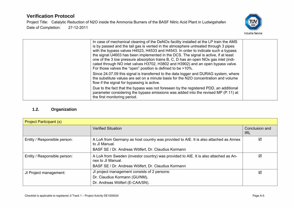
In case of mechanical cleaning of the DeNOx facility installed at the LP train the AMS is by passed and the tail gas is vented in the atmosphere untreated through 3 pipes with the bypass valves H4523, H4533 and H4543. In order to indicate such a bypass the signal U4603 has been implemented in the DCS. The signal is active, if at least one of the 3 low pressure absorption trains B, C, D has an open NOx gas inlet (indi-cated through NO inlet valves H3702, H3802 and H3902) and an open bypass valve. For those valves the “open” position is defined to be >10%. Since 24.07.09 this signal is transferred to the data logger and DURAG system, where the substitute values are set on a minute basis for the N2O concentration and volume flow if the signal for bypassing is active. Due to the fact that the bypass was not foreseen by the registered PDD, an additional parameter considering the bypass emissions was added into the revised MP (P.11) at the first monitoring period.
1.2. Organization
Project Participant (s)
Verified Situation Conclusion and IRL
Entity / Responsible person: A LoA from Germany as host country was provided to AIE. It is also attached as Annex to JI Manual. BASF SE / Dr. Andreas Wölfert, Dr. Claudius Kormann
Entity / Responsible person: A LoA from Sweden (investor country) was provided to AIE. It is also attached as An-nex to JI Manual. BASF SE / Dr. Andreas Wölfert, Dr. Claudius Kormann
JI Project management: JI project management consists of 2 persons: Dr. Claudius Kormann (GU/NM), Dr. Andreas Wölfert (E-CAA/SN).
Verification Protocol Project Title: Catalytic Reduction of N2O inside the Ammonia Burners of the BASF Nitric Acid Plant in Ludwigshafen Date of Completion: 27-12-2011
Checklist is applicable to registered JI Track 1 – Project Activity DE1000024 Page A-6
1.3. Quality Management System
General aspects of the Quality Management System
Verified Situation Conclusion and IRL
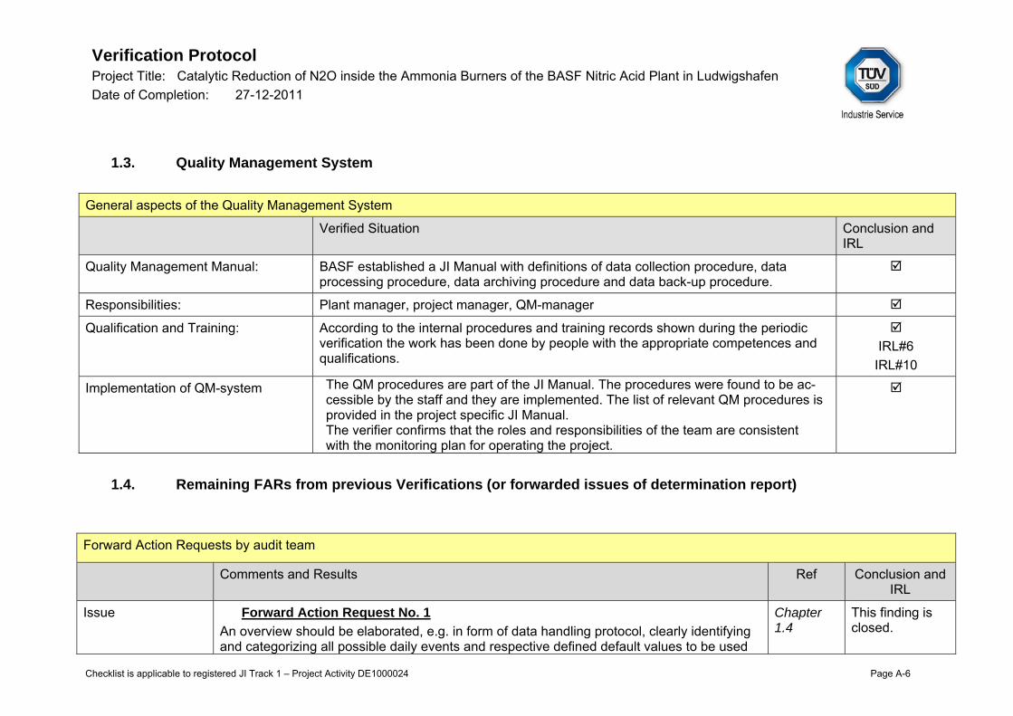
Quality Management Manual: BASF established a JI Manual with definitions of data collection procedure, data processing procedure, data archiving procedure and data back-up procedure.
Responsibilities: Plant manager, project manager, QM-manager
Qualification and Training: According to the internal procedures and training records shown during the periodic verification the work has been done by people with the appropriate competences and qualifications.
IRL#6
IRL#10
Implementation of QM-system The QM procedures are part of the JI Manual. The procedures were found to be ac-cessible by the staff and they are implemented. The list of relevant QM procedures is provided in the project specific JI Manual. The verifier confirms that the roles and responsibilities of the team are consistent with the monitoring plan for operating the project.
1.4. Remaining FARs from previous Verifications (or forwarded issues of determination report)
Forward Action Requests by audit team
Comments and Results Ref Conclusion and IRL
Issue Forward Action Request No. 1 An overview should be elaborated, e.g. in form of data handling protocol, clearly identifying and categorizing all possible daily events and respective defined default values to be used
Chapter 1.4
This finding is closed.

Verification Protocol Project Title: Catalytic Reduction of N2O inside the Ammonia Burners of the BASF Nitric Acid Plant in Ludwigshafen Date of Completion: 27-12-2011
Checklist is applicable to registered JI Track 1 – Project Activity DE1000024 Page A-7
Forward Action Requests by audit team
for the project parameters in case of a specific daily event. IRL#3a
IRL#3b
IRL#4 Response An overview of all possible daily events and respective defined default values for N2O de-
termination are given in the Excel Calculation Tool (sheets “DefValues_DeNOx_Start-up” and “Other_DefValues”). An overview of all defined and used default values for NAP deter-mination are given in the NAP Tool “2011_05_16_HNO3-Bilanz_Rev-3.xls”. With these two documents all project specific daily events and default values are documented in a transpa-rent way.
Assessment The assessment team checked the revised Excel calculation tool and NAP calculation tool. The daily events taken place during the 2nd monitoring period are clearly reported in the Excel Calculation Tool in sheets “DefValues_DeNOx_Start-up” and “Other_DefValues”. Fur-thermore a daily events list was elaborated by the PP and included in Annex 5.6.1.1 of JI Manual. The daily event list is updated for each monitoring period and serves for the cross- check with the events reported in the Excel calculation tool. The revised NAP tool presents the default values calculated as per the procedure provided in Annex 4.6 of JI Manual v. 2.1.
Forward Action Requests by audit team
Comments and Results Ref Conclusion and IRL
Issue Forward Action Request No. 2 For the future data handling, the bypass event at the LP train will be detected through the evaluation of the three NOx gas inlet flaps and bypass valves of the three absorption trains B, C, D indicates an open NOx gas inlet with a valve position > 10 % and an open bypass with a valve position > 10 %. If the valve positions are “open” for at least 1 minute, the entire respective hour is considered as bypass. This is considered as conservative. The respective procedure should be presented to the verifier at the next periodic verification.
Chapter 1.1
This finding is closed.
IRL#4

Verification Protocol Project Title: Catalytic Reduction of N2O inside the Ammonia Burners of the BASF Nitric Acid Plant in Ludwigshafen Date of Completion: 27-12-2011
Checklist is applicable to registered JI Track 1 – Project Activity DE1000024 Page A-8
Forward Action Requests by audit team
Response The procedure for DENOx bypass is described in chapter 6.1.1. of the project specific JI Manual in detail.
Assessment The audit team assessed the revised JI Manual v. 2.1 with special focus on its provisions for the data handling in case of the DeNOx bypass. The procedure described in Chapter 6.1.1 of the revised JI Manual now clearly describes the method of bypass detection and specific data handling.

Verification Protocol Project Title: Catalytic Reduction of N2O inside the Ammonia Burners of the BASF Nitric Acid Plant in Ludwigshafen Date of Completion: 27-12-2011
Checklist is applicable to registered JI Track 1 – Project Activity DE1000024 Page A-9
2. Monitoring Plan Implementation
2.1. Parameters
Parameters
Meth/tool PDD (informa-tion provided in MP)
MR Included in table Compliance Conclusion and IRL
Project specific approach based on AM0034
P1 NCSG
P1 NCSG
Chapter 2.2 Table 1 Compliant
Project specific approach based on AM0034
P2 VSG
P2 VSG
Chapter 2.2 Table 2 Compliant
Project specific approach based on AM0034
P3 PEn
P3 PEn
Calculated from P.1, P.2 and P.4 Chapter 3
Compliant
Project specific approach based on AM0034
P4 OH
P4 OH
Chapter 2.2 Table 3 Compliant
Project specific approach based on AM0034
P5 NAPn
P5 NAP
Chapter 2.2 Table 4 Compliant
Project specific approach based on AM0034
P6 TSG
P6 TSG
Chapter 2.2 Table 2 Compliant
Project specific approach based
P7 PSG
P7 PSG
Chapter 2.2 Table 2 Compliant
Verification Protocol Project Title: Catalytic Reduction of N2O inside the Ammonia Burners of the BASF Nitric Acid Plant in Ludwigshafen Date of Completion: 27-12-2011
Checklist is applicable to registered JI Track 1 – Project Activity DE1000024 Page A-10
Parameters
Meth/tool PDD (informa-tion provided in MP)
MR Included in table Compliance Conclusion and IRL
on AM0034
Project specific approach based on AM0034
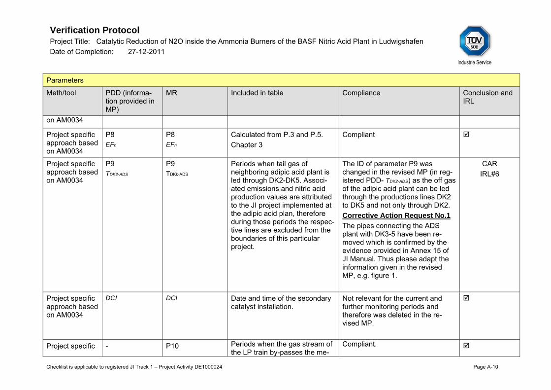
P8 EFn
P8 EFn
Calculated from P.3 and P.5. Chapter 3
Compliant
Project specific approach based on AM0034
P9 TDK2-ADS
P9 TDKk-ADS
Periods when tail gas of neighboring adipic acid plant is led through DK2-DK5. Associ-ated emissions and nitric acid production values are attributed to the JI project implemented at the adipic acid plan, therefore during those periods the respec-tive lines are excluded from the boundaries of this particular project.
The ID of parameter P9 was changed in the revised MP (in reg-istered PDD- TDK2-ADS) as the off gas of the adipic acid plant can be led through the productions lines DK2 to DK5 and not only through DK2. Corrective Action Request No.1
The pipes connecting the ADS plant with DK3-5 have been re-moved which is confirmed by the evidence provided in Annex 15 of JI Manual. Thus please adapt the information given in the revised MP, e.g. figure 1.
CAR IRL#6
Project specific approach based on AM0034
DCI DCI Date and time of the secondary catalyst installation.
Not relevant for the current and further monitoring periods and therefore was deleted in the re-vised MP.
Project specific - P10 Periods when the gas stream of the LP train by-passes the me-
Compliant.

Verification Protocol Project Title: Catalytic Reduction of N2O inside the Ammonia Burners of the BASF Nitric Acid Plant in Ludwigshafen Date of Completion: 27-12-2011
Checklist is applicable to registered JI Track 1 – Project Activity DE1000024 Page A-11
Parameters
Meth/tool PDD (informa-tion provided in MP)
MR Included in table Compliance Conclusion and IRL
approach based on AM0034
T_Bypass _DeNOx
tering devices of P.1 and P.2 due to cleaning activities of the DeNOx unit of the LP train. The source of data is the posi-tion of the butterfly valves Ohl Gutermuth KKD H4523 H4533 H4543
Project specific approach based on AM0034
B1 EFBL
B1 EFBL
Chapter 3 Compliant
Project specific approach based on AM0034
B2 NAP
B2 NAP
Chapter 2.2 Table 4 Compliant
Project specific approach based on AM0034
B3 TDK2-ADS
B3 TDKk-ADS
Periods when tail gas of neighboring adipic acid plant is led through DK2-DK5. Associ-ated emissions and nitric acid production values are attributed to the JI project implemented at the adipic acid plan, therefore during those periods the respec-tive lines are excluded from the boundaries of this particular project.
See comments to P.9 above. CAR IRL#6

Verification Protocol Project Title: Catalytic Reduction of N2O inside the Ammonia Burners of the BASF Nitric Acid Plant in Ludwigshafen Date of Completion: 27-12-2011
Checklist is applicable to registered JI Track 1 – Project Activity DE1000024 Page A-12
Parameters
Meth/tool PDD (informa-tion provided in MP)
MR Included in table Compliance Conclusion and IRL
Project specific approach based on AM0034
B4 EFreg
B4 EFreg
Chapter 2.4 Compliant
2.2. Parameters measured directly with instruments Table 1
Parameter and instrumentation Information
PDD /MP Meth/Tool MR Verified Conclusion and IRL
Parameter title N2O concen-tration in the stack gas
n/a N2O concentration in the stack gas Consistent
Parameter ID (if available)
P1 NCSG
n/a P1. NCSG Q3215, Q3315, Q3415, Q3515, Q4604
Consistent
Data Unit mgN2O/Nm³ n/a ppm/ Vol% N2O (Conversion of Vppm into mg/Nm3 by DURAG)
Consistent
Monitoring fre-quency (reading)
Continuously Once per minute/ Once
n/a Continuously Once per minute/ Once per second
Consistent

Verification Protocol Project Title: Catalytic Reduction of N2O inside the Ammonia Burners of the BASF Nitric Acid Plant in Ludwigshafen Date of Completion: 27-12-2011
Checklist is applicable to registered JI Track 1 – Project Activity DE1000024 Page A-13
per second Monitoring fre-quency (re-cording)
Hourly n/a Hourly Consistent
Calibration re-quirements
According to EN 14181
n/a According to EN ISO 14956 and EN 14181. Adjustment QAL3: weekly (BASF decision); AST: yearly (EN 14181); calibration QAL2: every 3 years (EN 14181); Analyzer with inter-nal calibration cuvette must be calibrated once per year with span gas. Latest QAL2/AST: DK2: QAL2- June 2010, AST- January 2010; DK 3 QAL2- June 2010, AST- August 2009;
PPs explained that DK4 is out of order since 30.07.2009; nevertheless a QAL2 was con-ducted on the AMS installed at this line. DK 5 : QAL2- June 2010, AST- 12.08.09 and 14.01.10 LP: QAL2- June 2010, AST- June 2009
Corrective Action Request No.2
The Annex 5.1.5 of JI Manual pro-vides an overview on the QAL 2 and AST tests conducted and reports whether the respective regression coefficients have been applied in the DURAG emission calculator. The PP is requested to update that overview taking into account the last QAL2s and ASTs performed. The information reported shall be con-sistent throughout the project documentation (MR, JI Manual, MP). Updated overview has to be provided to the audit team. Fur-thermore please provide the up-dated DURAG parameter list.
AST and QAL2 are provided as annex to the JI Manual (Annexes 5.1.5 and 5.1.6).
CAR IRL#6
IRL#7a
Uncertainty level Low System fulfils the latest applicable European standards and norms,
n/a 1% Consistent

Verification Protocol Project Title: Catalytic Reduction of N2O inside the Ammonia Burners of the BASF Nitric Acid Plant in Ludwigshafen Date of Completion: 27-12-2011
Checklist is applicable to registered JI Track 1 – Project Activity DE1000024 Page A-14
especially EN 14181 (registered PDD)
Measurement Principle (if ap-plicable)
Infra-Red online ana-lyzer
n/a IR photometry Consistent
Q3215 Technical aspects Conclusion and IRL
Instrument Type: IR- Photometer ABB AO2000-Uras 26
Serial Number: Q3215- 3.340917.9
Manufacturer Model Nr.:
ABB AO2000-Uras 26
Specific Loca-tion:
Q3215- DK2
Calibration re-quirements:
According to EN ISO 14956 and EN 14181. Adjustment QAL3: weekly (BASF decision); AST: yearly (EN 14181); calibration QAL2: every 3 years (EN 14181). The testing cells are to be recalibrated once a year during QAL2/AST acc. to the procedure “Küvette neu vermes-sen” Annex 5.1.5.e (relevant for Q 3315, Q 3415, Q 3515, Q 4604, Q 3215, Q 3115, Q 3173, Q 3273). The certificates for the test gas mixture have been provided (Annex 5.1.4.f of the JI Manual). The AST was conducted on 11.01.-15.01.2010.
The last QAL 2 was conducted on 22.-25.06.2010. The overall uncertainty of the measured N2O concentration is ± 2,69 %.
The records on the testing cells maintenance conducted in February 2010 and March 2011 has been provided to the assessment team.
IRL#6
Measurement Q3215- 0-5000 ppm (since May 08); 0-2000 ppm (since May 09); 0-10000 ppm (since May 09); 0-20 Vol% (since May 09; 0-30 Vol.% (since Oct 09)
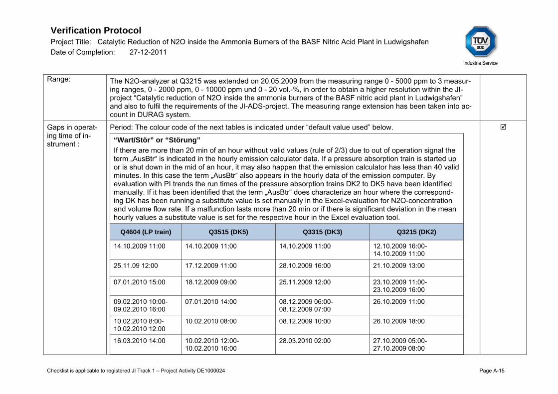
Verification Protocol Project Title: Catalytic Reduction of N2O inside the Ammonia Burners of the BASF Nitric Acid Plant in Ludwigshafen Date of Completion: 27-12-2011
Checklist is applicable to registered JI Track 1 – Project Activity DE1000024 Page A-15
Range: The N2O-analyzer at Q3215 was extended on 20.05.2009 from the measuring range 0 - 5000 ppm to 3 measur-ing ranges, 0 - 2000 ppm, 0 - 10000 ppm und 0 - 20 vol.-%, in order to obtain a higher resolution within the JI-project “Catalytic reduction of N2O inside the ammonia burners of the BASF nitric acid plant in Ludwigshafen” and also to fulfil the requirements of the JI-ADS-project. The measuring range extension has been taken into ac-count in DURAG system.
Gaps in operat-ing time of in-strument :
Period: The colour code of the next tables is indicated under “default value used” below.
“Wart/Stör” or “Störung”
If there are more than 20 min of an hour without valid values (rule of 2/3) due to out of operation signal the term „AusBtr“ is indicated in the hourly emission calculator data. If a pressure absorption train is started up or is shut down in the mid of an hour, it may also happen that the emission calculator has less than 40 valid minutes. In this case the term „AusBtr“ also appears in the hourly data of the emission computer. By evaluation with PI trends the run times of the pressure absorption trains DK2 to DK5 have been identified manually. If it has been identified that the term „AusBtr“ does characterize an hour where the correspond-ing DK has been running a substitute value is set manually in the Excel-evaluation for N2O-concentration and volume flow rate. If a malfunction lasts more than 20 min or if there is significant deviation in the mean hourly values a substitute value is set for the respective hour in the Excel evaluation tool.
Q4604 (LP train) Q3515 (DK5) Q3315 (DK3) Q3215 (DK2)
14.10.2009 11:00 14.10.2009 11:00 14.10.2009 11:00 12.10.2009 16:00-14.10.2009 11:00
25.11.09 12:00 17.12.2009 11:00 28.10.2009 16:00 21.10.2009 13:00
07.01.2010 15:00 18.12.2009 09:00 25.11.2009 12:00 23.10.2009 11:00-23.10.2009 16:00
09.02.2010 10:00-09.02.2010 16:00
07.01.2010 14:00 08.12.2009 06:00- 08.12.2009 07:00
26.10.2009 11:00
10.02.2010 8:00-10.02.2010 12:00
10.02.2010 08:00 08.12.2009 10:00 26.10.2009 18:00
16.03.2010 14:00 10.02.2010 12:00- 10.02.2010 16:00
28.03.2010 02:00 27.10.2009 05:00-27.10.2009 08:00

Verification Protocol Project Title: Catalytic Reduction of N2O inside the Ammonia Burners of the BASF Nitric Acid Plant in Ludwigshafen Date of Completion: 27-12-2011
Checklist is applicable to registered JI Track 1 – Project Activity DE1000024 Page A-16
23.03.2010 10:00-25.03.2010 09:00
18.02.2010 14:00 23.06.2010 10:00- 25.06.2010 09:00
28.10.2009 10:00-28.10.2009 12:00
28.03.2010 02:00 28.03.2010 02:00 28.10.2009 14:00-29.10.2009 09:00
14.04.2010 09:00 23.06.2010 10:00- 25.06.2010 09:00
29.10.2009 12:00-29.10.2009 17:00
18.05.2010 09:00 23.12.2010 11:00 03.11.2009 13:00-03.11.2009 15:00
19.05.2010 12.00 13.01.2011 20:00- 14.01.2011 07:00
23.12.2009 09:00
02.06.2010 09:00 18.01.2011 07:00- 18.01.2011 10:00
12.01.2010 09:00- 15.01.201 12:00
22.06.2010 15:00-28.06.2010 20:00
10.02.2010 12:00
29.06.2010 20:00-30.06.2010 15:00
15.03.2010 12:00
01.07.2010 09:00 16.03.2010 14:00
28.03.2010 02:00
07.04.2010 11:00
17.05.2010 16:00
22.06.2010 18:00-25.06.2010 09:00
30.06.2010 00:00-30.06.2010 08:00:
01.07.2010 09:00
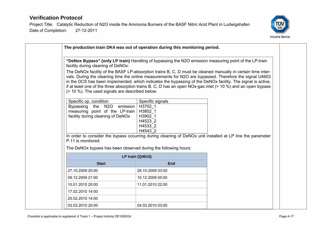
Verification Protocol Project Title: Catalytic Reduction of N2O inside the Ammonia Burners of the BASF Nitric Acid Plant in Ludwigshafen Date of Completion: 27-12-2011
Checklist is applicable to registered JI Track 1 – Project Activity DE1000024 Page A-17
The production train DK4 was out of operation during this monitoring period.
“DeNox Bypass” (only LP train) Handling of bypassing the N2O emission measuring point of the LP-train facility during cleaning of DeNOx: The DeNOx facility of the BASF LP-absorption trains B, C, D must be cleaned manually in certain time inter-vals. During the cleaning time the online measurements for N2O are bypassed. Therefore the signal U4603 in the DCS has been implemented, which indicates the bypassing of the DeNOx facility. The signal is active, if at least one of the three absorption trains B, C, D has an open NOx-gas inlet (> 10 %) and an open bypass (> 10 %). The used signals are described below. Specific op. condition Specific signals Bypassing the N2O emission measuring point of the LP-train facility during cleaning of DeNOx
H3702_1 H3802_1 H3902_1 H4523_2 H4533_2 H4543_2
In order to consider the bypass occurring during cleaning of DeNOx unit installed at LP line the parameter P.11 is monitored.
The DeNOx bypass has been observed during the following hours:
LP train (Q4615)
Start End
27.10.2009 20:00 28.10.2009 03:00
09.12.2009 21:00 10.12.2009 05:00
10.01.2010 20:00 11.01.2010 22:00
17.02.2010 14:00
25.02.2010 14:00
03.03.2010 20:00 04.03.2010 03:00

Verification Protocol Project Title: Catalytic Reduction of N2O inside the Ammonia Burners of the BASF Nitric Acid Plant in Ludwigshafen Date of Completion: 27-12-2011
Checklist is applicable to registered JI Track 1 – Project Activity DE1000024 Page A-18
01.04.2010 22:00 02.04.2010 05:00
06.04.2010 21:00 07.04.2010 21:00
03.05.2010 22:00 04.05.2010 09:00
07.06.2010 23:00 08.06.2010 06:00
28.06.2010 21:00 29.06.2010 19:00
22.07.2010 21:00 23.07.2010 05:00
16.08.2010 22:00 17.08.2010 20:00
14.09.2010 20:00 15.09.2010 04:00
28.09.2010 20:00 29.09.2010 21:00
04.10.2010 12:00
04.10.2010 14:00
04.10.2010 16:00
“Start-ups”
The start-up of a pressure absorption train starts with operating the train with air. During this phase the tem-peratures at the N2O-measuring point may be below 180°C. Then the NO-inlet is opened. Absorption of NO2 and emission of N2O starts. Due to the heat of reaction the temperature raises to about 250°C at the N2O-measuring point. There are indications that temperatures below 180°C will cause damage to the N2O-measuring system caused by formation of ammonia nitrate or by condensation of HNO3 in the measuring equipment. Therefore the measuring starts when the probing point has achieved a temperature of 180°C. The used signals are described below. Specific op. condition Specific signals Start-up of pressure absorption trains (DK2-DK5)
DK2 U3206 DK3 U3306 DK4 U3406 DK5 U3506
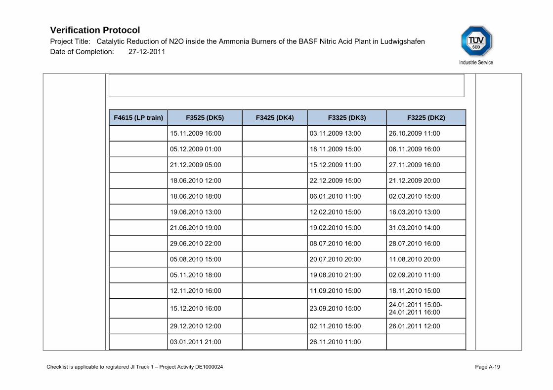
Verification Protocol Project Title: Catalytic Reduction of N2O inside the Ammonia Burners of the BASF Nitric Acid Plant in Ludwigshafen Date of Completion: 27-12-2011
Checklist is applicable to registered JI Track 1 – Project Activity DE1000024 Page A-19
F4615 (LP train) F3525 (DK5) F3425 (DK4) F3325 (DK3) F3225 (DK2)
15.11.2009 16:00 03.11.2009 13:00 26.10.2009 11:00
05.12.2009 01:00 18.11.2009 15:00 06.11.2009 16:00
21.12.2009 05:00 15.12.2009 11:00 27.11.2009 16:00
18.06.2010 12:00 22.12.2009 15:00 21.12.2009 20:00
18.06.2010 18:00 06.01.2010 11:00 02.03.2010 15:00
19.06.2010 13:00 12.02.2010 15:00 16.03.2010 13:00
21.06.2010 19:00 19.02.2010 15:00 31.03.2010 14:00
29.06.2010 22:00 08.07.2010 16:00 28.07.2010 16:00
05.08.2010 15:00 20.07.2010 20:00 11.08.2010 20:00
05.11.2010 18:00 19.08.2010 21:00 02.09.2010 11:00
12.11.2010 16:00 11.09.2010 15:00 18.11.2010 15:00
15.12.2010 16:00
23.09.2010 15:00 24.01.2011 15:00- 24.01.2011 16:00
29.12.2010 12:00 02.11.2010 15:00 26.01.2011 12:00
03.01.2011 21:00 26.11.2010 11:00

Verification Protocol Project Title: Catalytic Reduction of N2O inside the Ammonia Burners of the BASF Nitric Acid Plant in Ludwigshafen Date of Completion: 27-12-2011
Checklist is applicable to registered JI Track 1 – Project Activity DE1000024 Page A-20
26.01.2011 02:00 16.12.2010 12:00
18.02.2011 12:00 10.01.2011 20:00
24.01.2011 23:00
26.01.2011 21:00
06.02.2011 15:00
The production train DK4 was out of operation during this monitoring period. The LP process train oper-ated continuously without shutdowns.
Default value used: As substitute values for N2O concentration and normalized volume flow rate both for expected and unexpected failures the maximum values on an hourly basis of the sub period under evaluation are selected and applied manually in the Excel tool.
For 2nd monitoring period
Q4604 (LPtrain) Q3515 (DK 5) Q3415 (DK4) Q3315 (DK 3) Q3215 (DK 2)
NCSG
[mg/Nm3] 6038,6 1624,6 - 1661 1015,9
Justification: The highest measured value of the sub period is applied in case of malfunctioning as default value. This is found to be conservative and in line with PDD and the applied methodology.
Q3315 Technical aspects Conclusion and IRL
Instrument Type: IR- Photometer ABB AO2000-Uras 26
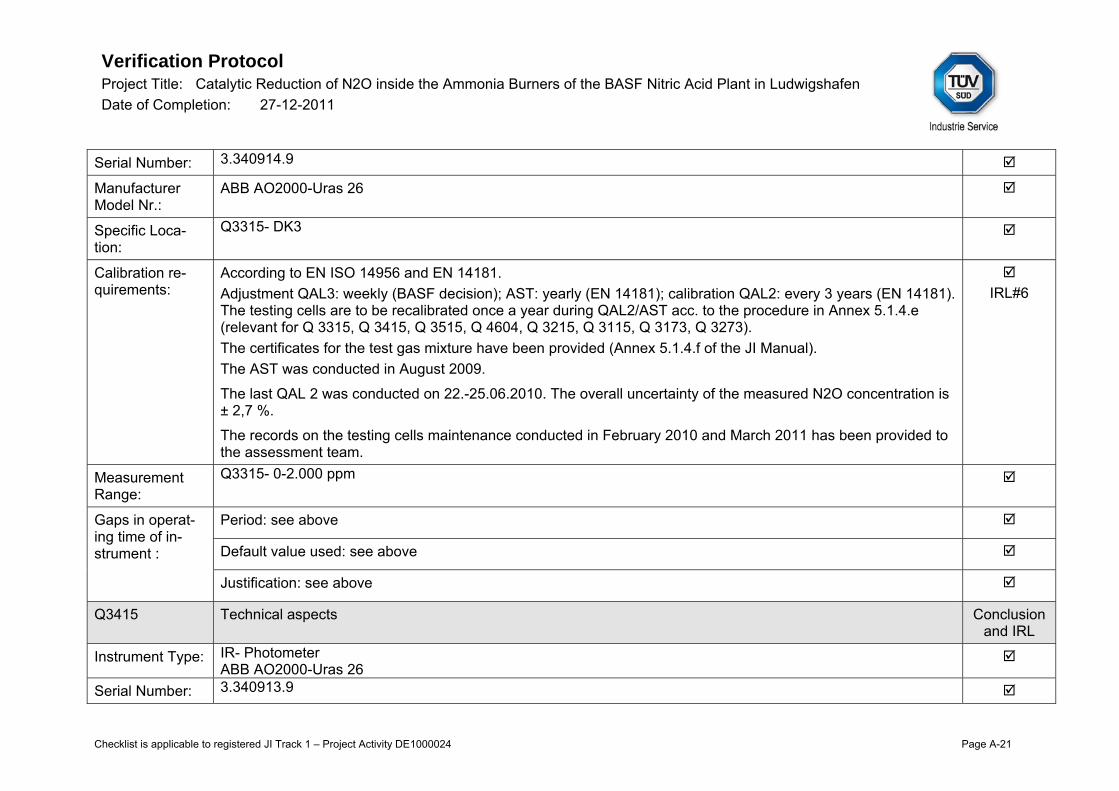
Verification Protocol Project Title: Catalytic Reduction of N2O inside the Ammonia Burners of the BASF Nitric Acid Plant in Ludwigshafen Date of Completion: 27-12-2011
Checklist is applicable to registered JI Track 1 – Project Activity DE1000024 Page A-21
Serial Number: 3.340914.9
Manufacturer Model Nr.:
ABB AO2000-Uras 26
Specific Loca-tion:
Q3315- DK3
Calibration re-quirements:
According to EN ISO 14956 and EN 14181. Adjustment QAL3: weekly (BASF decision); AST: yearly (EN 14181); calibration QAL2: every 3 years (EN 14181). The testing cells are to be recalibrated once a year during QAL2/AST acc. to the procedure in Annex 5.1.4.e (relevant for Q 3315, Q 3415, Q 3515, Q 4604, Q 3215, Q 3115, Q 3173, Q 3273). The certificates for the test gas mixture have been provided (Annex 5.1.4.f of the JI Manual). The AST was conducted in August 2009.
The last QAL 2 was conducted on 22.-25.06.2010. The overall uncertainty of the measured N2O concentration is ± 2,7 %.
The records on the testing cells maintenance conducted in February 2010 and March 2011 has been provided to the assessment team.
IRL#6
Measurement Range:
Q3315- 0-2.000 ppm
Gaps in operat-ing time of in-strument :
Period: see above
Default value used: see above
Justification: see above
Q3415 Technical aspects Conclusion and IRL
Instrument Type: IR- Photometer ABB AO2000-Uras 26
Serial Number: 3.340913.9

Verification Protocol Project Title: Catalytic Reduction of N2O inside the Ammonia Burners of the BASF Nitric Acid Plant in Ludwigshafen Date of Completion: 27-12-2011
Checklist is applicable to registered JI Track 1 – Project Activity DE1000024 Page A-22
Manufacturer Model Nr.:
ABB AO2000-Uras 26
Specific Loca-tion:
Q3415- DK4
Calibration re-quirements:
According to EN ISO 14956 and EN 14181. Adjustment QAL3: weekly (BASF decision); AST: yearly (EN 14181); calibration QAL2: every 3 years (EN 14181). The testing cells are to be recalibrated once a year during QAL2/AST acc. to the procedure “Küvette neu vermes-sen” Annex 5.1.5.e (relevant for Q 3315, Q 3415, Q 3515, Q 4604, Q 3215, Q 3115, Q 3173, Q 3273). The certificates for the test gas mixture have been provided (Annex 5.1.5.f of the JI Manual). AST has not been conducted as required by the EN 14181 as DK 4 is s out of operation since 30.07.2009.
The last QAL 2 was conducted on 22.-25.06.2010 and its results were implemented in the DURAG evaluation program. The overall uncertainty of the measured N2O concentration is ± 2,71 %.
The records on the testing cells maintenance conducted in February 2010 and March 2011 has been provided to the assessment team.
IRL#6
Measurement Range:
Q3415- 0-2.000 ppm
Gaps in operat-ing time of in-strument :
Period: production line DK 4 and therefore the respective AMS is out of operation since 30.07.09, see also above.
Default value used: see above
Justification: see above
Q3515 Technical aspects Conclusion and IRL
Instrument Type: IR- Photometer ABB AO2000-Uras 26
Serial Number: Q3515- 3.340916.9
Manufacturer ABB AO2000-Uras 26

Verification Protocol Project Title: Catalytic Reduction of N2O inside the Ammonia Burners of the BASF Nitric Acid Plant in Ludwigshafen Date of Completion: 27-12-2011
Checklist is applicable to registered JI Track 1 – Project Activity DE1000024 Page A-23
Model Nr.:
Specific Loca-tion:
Q3515- DK5
Calibration re-quirements:
According to EN ISO 14956 and EN 14181. Adjustment QAL3: weekly (BASF decision); AST: yearly (EN 14181); calibration QAL2: every 3 years (EN 14181). The testing cells are to be recalibrated once a year during QAL2/AST acc. to the procedure “Küvette neu vermes-sen” Annex 5.1.5.e (relevant for Q 3315, Q 3415, Q 3515, Q 4604, Q 3215, Q 3115, Q 3173, Q 3273). The certificates for the test gas mixture have been provided (Annex 5.1.5.f of the JI Manual). AST was conducted in January 2010.
The last QAL 2 was conducted on 22.-25.06.2010 and its results were implemented in the DURAG evaluation program. The overall uncertainty of the measured N2O concentration is ± 2,69 %.
The records on the testing cells maintenance conducted in February 2010 and March 2011 has been provided to the assessment team.
IRL#6
Measurement Range:
Q3515- 0-2.000 ppm
Gaps in operat-ing time of in-strument :
Period: see above
Default value used: see above
Justification: see above
Q4604 Technical aspects Conclusion and IRL
Instrument Type: IR- Photometer ABB AO2000-Uras 26
Serial Number: 3.340915.8
Manufacturer Model Nr.:
ABB AO2000-Uras 26

Verification Protocol Project Title: Catalytic Reduction of N2O inside the Ammonia Burners of the BASF Nitric Acid Plant in Ludwigshafen Date of Completion: 27-12-2011
Checklist is applicable to registered JI Track 1 – Project Activity DE1000024 Page A-24
Specific Loca-tion:
Q4604- LP
Calibration re-quirements:
According to EN ISO 14956 and EN 14181. QAL 1 certificate for ABB AO2000-Uras 26 has been provided. Adjustment QAL3: weekly (BASF decision); AST: yearly (EN 14181); calibration QAL2: every 3 years (EN 14181). The testing cells are to be recalibrated once a year during QAL2/AST acc. to the procedure “Küvette neu vermes-sen” Annex 5.1.5.e (relevant for Q 3315, Q 3415, Q 3515, Q 4604, Q 3215, Q 3115, Q 3173, Q 3273).
The certificates for the test gas mixture have been provided (Annex 5.1.5.f of the JI Manual). AST was conducted in June 2009.
The last QAL 2 was conducted on 22.-25.06.2010 and its results were implemented in the DURAG evaluation program. The overall uncertainty of the measured N2O concentration is ± 2,87 %.
The records on the testing cells maintenance conducted in February 2010 and March 2011 has been provided to the assessment team.
IRL#6
Measurement Range:
0-2000 ppm extended in Fabruary 2010 to: 0-2000 ppm 0-10000 ppm 0-30Vol% The operating range of the N2O-analyzer at Q4604 was extended as indicated above in order to obtain a higher resolution within the JI-project “Catalytic reduction of N2O inside the ammonia burners of the BASF nitric acid plant in Ludwigshafen” and also to fulfil the requirements of the JI-ADS-project. The measuring range extension has been taken into account in DURAG system.
Gaps in operat-ing time of in-strument :
Period: see above
Default value used: see above
Justification: see above
QA/QC aspects Conclusion

Verification Protocol Project Title: Catalytic Reduction of N2O inside the Ammonia Burners of the BASF Nitric Acid Plant in Ludwigshafen Date of Completion: 27-12-2011
Checklist is applicable to registered JI Track 1 – Project Activity DE1000024 Page A-25
and IRL
Source of data The data is automatically recorded in the Delta V system (DCS) and DURAG system. It is provided as hourly av-erages in raw data sheet Excel sheet which is derived from DURAG system (csv.files). The signal / loop check was conducted on 20.05.2008 for all measurement parameters and repeated on 26.07.2010 for the TSG (T4615). Clarification Request No. 2 The PP is requested to clarify the necessary frequency of the loop check (e.g. supplier recommendations) to be conducted for the measurements. The moisture content in the stack gases of the LP train was determined according to DIN EN 14790 on 3.08.2010. It was found to be in the range of 12.09 – 13.98 Vol% (see IRL#7). Option C of the methodological tool “Tool to determine the mass flow of a greenhouse gas in a gaseous stream” was applied, and volumetric flow of dry gas was calculated using (conservative) lowest moisture content measured:
%91,87
wetdry VV Type: digital
CR IRL#6
IRL#7a IRL#9
Procedures: JI Manual section 3.3, Annex 3.2.1 “Overview metering points N2O monitoring & signal list”, Annex 5.1.5.
IRL#6 IRL#7
Implementation of procedure: Reviewing the project documents it can be confirmed that procedures are imple-mented.
Responsibility: JI Project Manager
Archiving of raw data and protec-tion measures
The N2O-concentration measured by the IR-spectroscope URAS 26 and the volume flow rate and the associated temperature and pressure are logged as process signals in the data logging unit of DURAG system. From the data logging unit process signals are connected, converted and transmitted to the data processor which is in-stalled in the control room O405 and is operated by the plant manager. The data are stored every minute for 30 d on the data logger. In addition, every day a copy of the new data is created and stored on a backup –server. The online measurements are also processed in the DCS of the nitric acid plant where they are consolidated with additional field measurement data (e.g. flap positions, compressor dives etc.) for identification of the operating

Verification Protocol Project Title: Catalytic Reduction of N2O inside the Ammonia Burners of the BASF Nitric Acid Plant in Ludwigshafen Date of Completion: 27-12-2011
Checklist is applicable to registered JI Track 1 – Project Activity DE1000024 Page A-26
status. In case of special events (by-passing, feed of Adipic acid off-gas etc.) special signals are generated and processed in the Durag-Computer. Permanent data archiving of the main server D-EMS 2000 takes place on the monitoring system until the hard disc is full, minimum 10 years. Additionally, a copy of the new data is created and stored on the production net-work of the VM-Ware server. This external data backup is controlled every 24h; in case of failure the office for communication technology and IT-security will be notified by the monitoring software.
Data transfer and protection of input data for calculations
The data is manually exported via csv-file from the DURAG system in the Excel calculation tool. After final determination of calculation procedures data is stored in Excel-Files which are protected against un-wanted changes by “writing protection”. In addition the final version of an excel file will be printed as PDF-File.
Quality of evidence Conclusion and IRL
Completeness of data
The DURAG data were reviewed on the period and showed complete and credible data. Any deviation is de-scribed above in section “Gaps in operating time of instrument”.
Data verification DURAG data of each sub period was traced by graph. Any peculiarity was focussed with special awareness and discussed onsite. Any event resulted in setting default value is described above in section “Gaps in operating time of instrument” above.
According to the EN 14181 applied the validity of the valid calibration range determined during the QAL 2 shall be evaluated by the plant owner afterwards on a weekly basis. A full new QAL2 shall be performed, reported and implemented within 6 months, if any of the following conditions occur: - more than 5 % of the number of AMS measured values calculated over this weekly period (based on normalized calibrated values) are outside the valid calibration range for more than 5 weeks in the period between two ASTs; - more than 40 % of the number of AMS measured values calculated over this weekly period (based on normal-ized calibrated values) are outside the valid calibration range for one or more weeks.
During the on-site visit the analysis on validity of calibration ranges has been demonstrated to the assessment team. This conformity test (as per EN 14181) shows a very few values measured outside of the valid calibration range and therefore the abovementioned EN 14181 criteria is deemed met. Clarification Request No. 3 According to the EN 14181 applied the validity of the calibration range determined during the QAL 2 has to be observed by the operator. Therefore please include the EN 14181 conformity test for the relevant monitoring pe-
CR IRL#6
IRL#7a
IRL#7b

Verification Protocol Project Title: Catalytic Reduction of N2O inside the Ammonia Burners of the BASF Nitric Acid Plant in Ludwigshafen Date of Completion: 27-12-2011
Checklist is applicable to registered JI Track 1 – Project Activity DE1000024 Page A-27
riod into the JI Manual (e.g. as an Annex). The revised JI Manual should be provided to the assessment team.
QAL 3 is maintained by PPs and zero and span checks are periodically conducted.
Clarification Request No. 4 The real time data check conducted by the auditors during the physical site inspection did not show the credible and consistent data: e.g. the immediately measured values at Q4604 did not comply with the respective values registered in the PI system and DURAG system. The PP is requested to clarify the reason for this difference as DURAG system is a source of the hourly raw data used for the ER calculation. Moreover the correctness and reliability of the DURAG data provided for the relevant monitoring period must be confirmed.
Consistency of calculation tool with monitoring report: Not applicable as this parameter is not reported in the MR. The MR reports project and baseline emission and emission reductions.
Cross-check (if available)
Not available
Table 2
Parameter and instrumentation Information
PDD /MP Meth/Tool MR Verified Conclusion and IRL
Parameter title Volume flow rate of the stack gas
n/a Volume flow rate of the stack gas
Consistent
Parameter ID (if available) P2 VSG
n/a P2 VSG F3225, F3325, F3425, F3525, F4615
Consistent
Data Unit Nm³/h n/a Nm³/h Consistent

Verification Protocol Project Title: Catalytic Reduction of N2O inside the Ammonia Burners of the BASF Nitric Acid Plant in Ludwigshafen Date of Completion: 27-12-2011
Checklist is applicable to registered JI Track 1 – Project Activity DE1000024 Page A-28
(normalized with pres-sure and temperature T3225, P3225, T3325, P3325, T3425, P3425, T3525, P3525, T4615, P4615.
Monitoring frequency (reading) Continuously n/a Continuously Consistent
Monitoring frequency (recording) Hourly n/a Hourly Consistent
Calibration requirements According to EN 14181.
n/a Maintenance/adjustment: yearly acc. to the proce-dure described in Annex 5.2.2 of the JI Manual (BASF decision). According to EN 14181: AST: yearly (EN 14181); QAL2: every 3 years (EN 14181).
Consistent
Uncertainty level Low System fulfils the latest applicable European stan-dards and norms, especially EN 14181.
n/a +/- 2% Consistent
Measurement Principle (if applica-ble)
Differential pres-sure technique
n/a Differential pressure technique
Consistent
F3225 Technical aspects Conclusion and IRL

Verification Protocol Project Title: Catalytic Reduction of N2O inside the Ammonia Burners of the BASF Nitric Acid Plant in Ludwigshafen Date of Completion: 27-12-2011
Checklist is applicable to registered JI Track 1 – Project Activity DE1000024 Page A-29
Instrument Type: Differential pressure flow meter (wet basis)
Serial Number: 11142-01
Manufacturer Model Nr.:
Systec, deltaflow DF 25 Typ 23
Specific Location: F3225- DK 2 behind C 3201
Calibration re-quirements:
Maintenance/adjustment: yearly acc. to the procedure described in Annex 5.2.2 of the JI Manual (BASF deci-sion); According to EN ISO 14956 and EN 14181. AST: yearly (EN 14181); QAL2: every 3 years (EN 14181); maintenance/ adjustment: annually. QAL 2: 28.-30.07.2008 AST: 11.01.- 15.01.2010 Annual maintenance: 26.07.2010 Clarification Request No. 5 During the physical plant inspection the maintenance plan has been presented to the assessment team. The auditors cross- checked the plan with the original maintenance certificates and records, and can confirm that the measuring devices installed have been maintained properly and in time. However please amend the mainten-ance plan by including the LP DeNOx bypass valves and respective maintenance dates. The revised mainten-ance plan has to be submitted to the audit team. Please also provide copies of the maintenance certificates cross- checked on-site (for F3225, T3235, P3225) and report on the last inspection of the bypass valves con-ducted in 2010.
CR IRL#6
Measurement Range:
F3225- 0-50.000 m³/h
Gaps in operat-ing time of in-strument :
Period:
“Wart/Stör” or “Störung”
If there are more than 20 min of an hour without valid values (rule of 2/3) due to out of operation signal the term „AusBtr“ is indicated in the hourly emission calculator data. If a pressure absorption train is started up or is shut down in the mid of an hour, it may also happen that the emission calculator has less than 40 valid minutes. In this case the term „AusBtr“ also appears in the hourly data of the emission computer. By evalua-

Verification Protocol Project Title: Catalytic Reduction of N2O inside the Ammonia Burners of the BASF Nitric Acid Plant in Ludwigshafen Date of Completion: 27-12-2011
Checklist is applicable to registered JI Track 1 – Project Activity DE1000024 Page A-30
tion with PI trends the run times of the pressure absorption trains DK2 to DK5 have been identified manually. If it has been identified that the term „AusBtr“ characterizes an hour where the corresponding DK has been running a substitute value is set manually in the Excel-evaluation for N2O-concentration and volume flow rate. If a malfunction lasts more than 20 min or if there is significant deviation in the mean hourly values a substitute value is set for the respective hour in the Excel evaluation tool.
F4615 (LP train) F3525 (DK5) F3325 (DK3) F3225 (DK2)
07.01.2010 14:00- 07.01.2009 15:00
05.12.2009 02:00- 17.12.2009 11:00
08.12.2009 06:00- 08.12.2009 07:00
23.10.2009 08:00- 03.11.2009 15:00
28.03.2010 02:00 18.12.2009 09:00 08.12.2009 10:00 07.01.2010 12:00- 07.01.2010 16:00
07.07.2010 09:00- 07.07.2010 15:00
07.01.2010 14:00- 07.01.2010 15:00
07.01.2010 14:00- 07.01.2010 15:00
28.03.2010 02:00
08.07.2010 15:00 28.03.2010 02:00 28.03.2010 02:00 26.07.2010 08:00- 27.07.2010 02:00
09.07.2010 11:00- 09.07.2010 14:00
14.07.2010 15:00 23.06.2010 10:00- 25.06.2010 09:00
14.07.2010 09:00 23.12.2010 11:00 06.07.2010 09:00- 06.07.2010 15:00
14.07.2010 12:00 13.01.2011 20:00- 14.01.2011 07:00
18.01.2011 07:00- 18.01.2011 10:00
19.01.2011 08:00- 19.01.2011 16:00
The production train DK4 was out of operation during this monitoring period.
“DeNox Bypass” (only LP train) Handling of bypassing the N2O emission measuring point of the LP-train facility during cleaning of DeNOx:

Verification Protocol Project Title: Catalytic Reduction of N2O inside the Ammonia Burners of the BASF Nitric Acid Plant in Ludwigshafen Date of Completion: 27-12-2011
Checklist is applicable to registered JI Track 1 – Project Activity DE1000024 Page A-31
The DeNOx facility of the BASF LP-absorption trains B, C, D must be cleaned manually in certain time inter-vals. During the cleaning time the online measurements for N2O are bypassed. Therefore the signal U4603 in the DCS has been implemented, which indicates the bypassing of the DeNOx facility. The signal is active, if at least one of the three absorption trains B, C, D has an open NOx-gas inlet (> 10 %) and an open bypass (> 10 %). The used signals are described below. Specific op. condition Specific signals Bypassing the N2O emission measuring point of the LP-train facility during cleaning of DeNOx
H3702_1 H3802_1 H3902_1 H4523_2 H4533_2 H4543_2
In order to consider the bypass occurring during cleaning of DeNOx unit installed at LP line the parameter P.11 is monitored.
The DeNOx bypass has been observed during the following hours:
LP train (F4615)
Start End
27.10.2009 20:00 28.10.2009 03:00
09.12.2009 21:00 10.12.2009 05:00
10.01.2010 20:00 11.01.2010 22:00
17.02.2010 14:00
25.02.2010 14:00
03.03.2010 20:00 04.03.2010 03:00
01.04.2010 22:00 02.04.2010 05:00
06.04.2010 21:00 07.04.2010 21:00

Verification Protocol Project Title: Catalytic Reduction of N2O inside the Ammonia Burners of the BASF Nitric Acid Plant in Ludwigshafen Date of Completion: 27-12-2011
Checklist is applicable to registered JI Track 1 – Project Activity DE1000024 Page A-32
03.05.2010 22:00 04.05.2010 09:00
07.06.2010 23:00 08.06.2010 06:00
28.06.2010 21:00 29.06.2010 19:00
22.07.2010 21:00 23.07.2010 05:00
16.08.2010 22:00 17.08.2010 20:00
14.09.2010 20:00 15.09.2010 04:00
28.09.2010 20:00 29.09.2010 21:00
04.10.2010 12:00
04.10.2010 14:00
04.10.2010 16:00
07.11.2010 20:00 12.11.2010 19:00
02.01.2011 23:00 03.01.2011 21:00
16.02.2011 21:00 17.02.2011 23:00
“Start-ups”
The start-up of a pressure absorption train starts with operating the train with air. During this phase the tem-peratures at the N2O-measuring point may be below 180°C. Then the NO-inlet is opened. Absorption of NO2 and emission of N2O starts. Due to the heat of reaction the temperature raises to about 250°C at the N2O-measuring point. There are indications that temperatures below 180°C will cause damage to the N2O-measuring system caused by formation of ammonia nitrate or by condensation of HNO3 in the measuring equipment. Therefore the measuring starts when the probing point has achieved a temperature of 180°C. The used signals are described below. Specific op. condition Specific signals Start-up of pressure absorption trains (DK2-DK5)
DK2 U3206 DK3 U3306 DK4 U3406

Verification Protocol Project Title: Catalytic Reduction of N2O inside the Ammonia Burners of the BASF Nitric Acid Plant in Ludwigshafen Date of Completion: 27-12-2011
Checklist is applicable to registered JI Track 1 – Project Activity DE1000024 Page A-33
DK5 U3506
F4615 (LP train) F3525 (DK5) F3425 (DK4) F3325 (DK3) F3225 (DK2)
15.11.2009 16:00 03.11.2009 13:00 26.10.2009 11:00
05.12.2009 01:00 18.11.2009 15:00 06.11.2009 16:00
21.12.2009 05:00 15.12.2009 11:00 27.11.2009 16:00
18.06.2010 12:00 22.12.2009 15:00 21.12.2009 20:00
18.06.2010 18:00 06.01.2010 11:00 02.03.2010 15:00
19.06.2010 13:00 12.02.2010 15:00 16.03.2010 13:00
21.06.2010 19:00 19.02.2010 15:00 31.03.2010 14:00
29.06.2010 22:00 08.07.2010 16:00 28.07.2010 16:00
05.08.2010 15:00 20.07.2010 20:00 11.08.2010 20:00
05.11.2010 18:00 19.08.2010 21:00 02.09.2010 11:00
12.11.2010 16:00 11.09.2010 15:00 18.11.2010 15:00
15.12.2010 16:00
23.09.2010 15:00 24.01.2011 15:00- 24.01.2011 16:00
29.12.2010 12:00 02.11.2010 15:00 26.01.2011 12:00
03.01.2011 21:00 26.11.2010 11:00

Verification Protocol Project Title: Catalytic Reduction of N2O inside the Ammonia Burners of the BASF Nitric Acid Plant in Ludwigshafen Date of Completion: 27-12-2011
Checklist is applicable to registered JI Track 1 – Project Activity DE1000024 Page A-34
26.01.2011 02:00 16.12.2010 12:00
18.02.2011 12:00 10.01.2011 20:00
24.01.2011 23:00
26.01.2011 21:00
06.02.2011 15:00
The production train DK4 was out of operation during this monitoring period. The LP process train oper-ated continuously without shutdowns.
Default value used: As substitute values for N2O concentration and normalized volume flow rate both for expected and unexpected failures the maximum values on an hourly basis of the sub period under evaluation are selected and applied manually in the Excel tool.
For 2nd monitoring period
F4615 (LP train) F3525 (DK5) F3425 (DK4) F3325 (DK3) F3225 (DK2)
VSG [Nm3/h] 139034 44955,6 - 47310 45978,7
Justification: The highest measured value of the sub period is applied in case of malfunctioning as default value. This is found to be conservative and in line with PDD and the applied methodology.
F3325 Technical aspects Conclusion and IRL
Instrument Type: Differential pressure flow meter (wet basis)
Serial Number: 11142-02
Manufacturer Model Nr.:
Systec, deltaflow DF 25 Typ 23

Verification Protocol Project Title: Catalytic Reduction of N2O inside the Ammonia Burners of the BASF Nitric Acid Plant in Ludwigshafen Date of Completion: 27-12-2011
Checklist is applicable to registered JI Track 1 – Project Activity DE1000024 Page A-35
Specific Location: F3325- DK3 behind C 3301
Calibration re-quirements:
Maintenance/adjustment: yearly acc. to the procedure described in Annex 5.2.2 of the JI Manual (BASF deci-sion); According to EN ISO 14956 and EN 14181. AST: yearly (EN 14181); QAL2: every 3 years (EN 14181); maintenance/ adjustment: annually. QAL 2: 28.-30.07.2008 AST: 12.08.2009 Annual maintenance: 06.07.2010
Measurement Range:
0-50.000 m³/h
Gaps in operat-ing time of in-strument :
Period: see above
Default value used: see above
Justification: see above
F3425 Technical aspects Conclusion and IRL
Instrument Type: Differential pressure flow meter (wet basis)
Serial Number: 11142-03
Manufacturer Model Nr.:
Systec, deltaflow DF 25 Typ 23
Specific Location: F3425- DK 4 behind C 3401
Calibration re-quirements:
Maintenance/adjustment: yearly acc. to the procedure described in Annex 5.2.2 of the JI Manual (BASF deci-sion); According to EN ISO 14956 and EN 14181.

Verification Protocol Project Title: Catalytic Reduction of N2O inside the Ammonia Burners of the BASF Nitric Acid Plant in Ludwigshafen Date of Completion: 27-12-2011
Checklist is applicable to registered JI Track 1 – Project Activity DE1000024 Page A-36
AST: yearly (EN 14181); QAL2: every 3 years (EN 14181); maintenance/ adjustment: annually. QAL 2: 28.-30.07.2008 Annual maintenance: 20.06.2008 (is dismantled currently due to shut down of DK4 since 2009).
Measurement Range:
0-50.000 m³/h
Gaps in operat-ing time of in-strument :
Period: see above
Default value used: see above
Justification: see above
F3525 Technical aspects Conclusion and IRL
Instrument Type: Differential pressure flow meter (wet basis)
Serial Number: 11142-04
Manufacturer Model Nr.:
Systec, deltaflow DF 25 Typ 23
Specific Location: F3525- DK5 behind C 3501
Calibration re-quirements:
Maintenance/adjustment: yearly acc. to the procedure described in Annex 5.2.2 of the JI Manual (BASF deci-sion); According to EN ISO 14956 and EN 14181. AST: yearly (EN 14181); QAL2: every 3 years (EN 14181); maintenance/ adjustment: annually. QAL 2: 28.-30.07.2008 AST: 12. 08.2009 & 14.01.2010 Annual maintenance: 19.01.2011
CR IRL#6
Measurement Range:
F3525- 0-50.000 m³/h

Verification Protocol Project Title: Catalytic Reduction of N2O inside the Ammonia Burners of the BASF Nitric Acid Plant in Ludwigshafen Date of Completion: 27-12-2011
Checklist is applicable to registered JI Track 1 – Project Activity DE1000024 Page A-37
Gaps in operat-ing time of in-strument :
Period: see above
Default value used: see above
Justification: see above
F4615 Technical aspects Conclusion and IRL
Instrument Type: Differential pressure flow meter (wet basis)
Serial Number: 11142-05
Manufacturer Model Nr.:
Systec, deltaflow DF 25 Typ 23
Specific Location: F4615- LP Stack A 4601
Calibration re-quirements:
Maintenance/adjustment: yearly acc. to the procedure described in Annex 5.2.2 of the JI Manual (BASF deci-sion); According to EN ISO 14956 and EN 14181. AST: yearly (EN 14181); QAL2: every 3 years (EN 14181); maintenance/ adjustment: annually. QAL 2: 22.-25.06.2010 AST: 23.06.- 24.06.2009 Annual maintenance: 07.07.2010
IRL#6
Measurement Range:
0-200.000 m³/h
Gaps in operat-ing time of in-strument :
Period: see above
Default value used: see above
Justification: see above
QA/QC aspects Conclusion and IRL
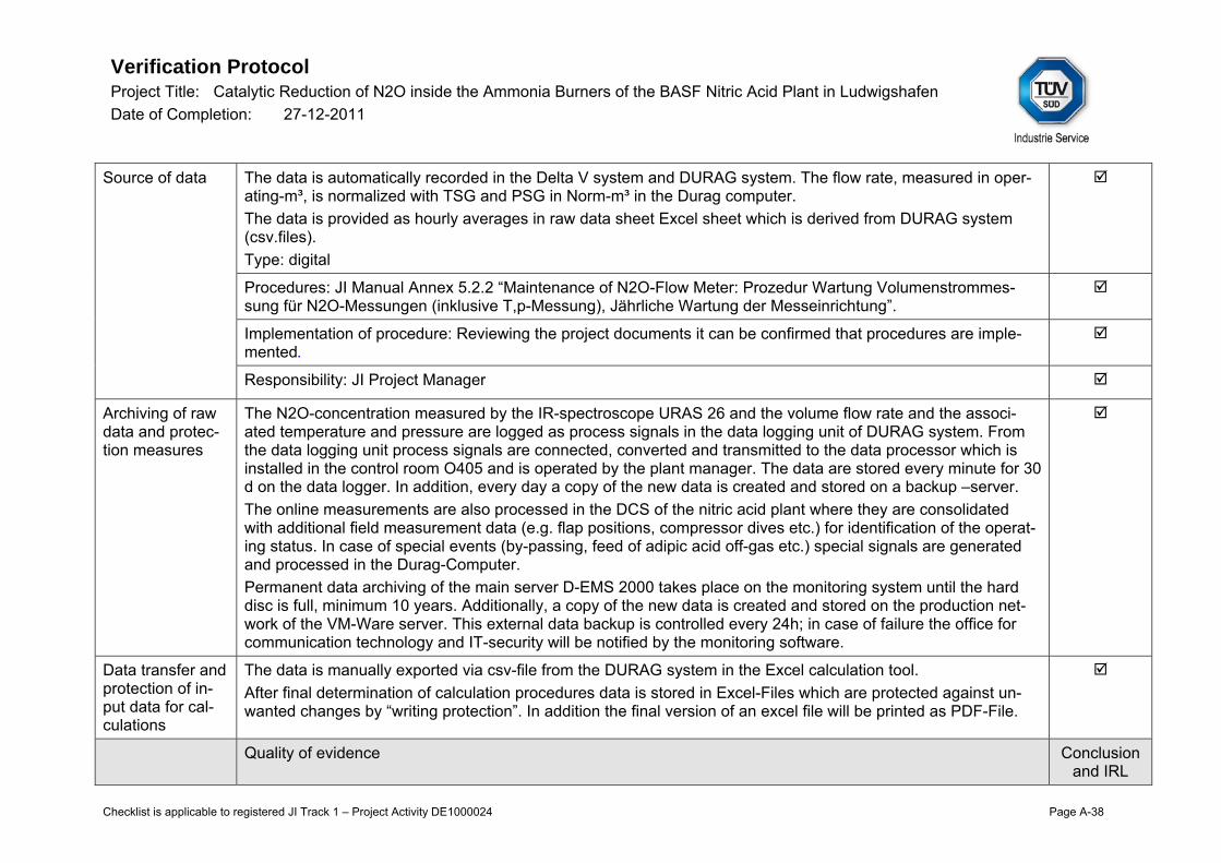
Verification Protocol Project Title: Catalytic Reduction of N2O inside the Ammonia Burners of the BASF Nitric Acid Plant in Ludwigshafen Date of Completion: 27-12-2011
Checklist is applicable to registered JI Track 1 – Project Activity DE1000024 Page A-38
Source of data The data is automatically recorded in the Delta V system and DURAG system. The flow rate, measured in oper-ating-m³, is normalized with TSG and PSG in Norm-m³ in the Durag computer. The data is provided as hourly averages in raw data sheet Excel sheet which is derived from DURAG system (csv.files). Type: digital
Procedures: JI Manual Annex 5.2.2 “Maintenance of N2O-Flow Meter: Prozedur Wartung Volumenstrommes-sung für N2O-Messungen (inklusive T,p-Messung), Jährliche Wartung der Messeinrichtung”.
Implementation of procedure: Reviewing the project documents it can be confirmed that procedures are imple-mented.
Responsibility: JI Project Manager
Archiving of raw data and protec-tion measures
The N2O-concentration measured by the IR-spectroscope URAS 26 and the volume flow rate and the associ-ated temperature and pressure are logged as process signals in the data logging unit of DURAG system. From the data logging unit process signals are connected, converted and transmitted to the data processor which is installed in the control room O405 and is operated by the plant manager. The data are stored every minute for 30 d on the data logger. In addition, every day a copy of the new data is created and stored on a backup –server. The online measurements are also processed in the DCS of the nitric acid plant where they are consolidated with additional field measurement data (e.g. flap positions, compressor dives etc.) for identification of the operat-ing status. In case of special events (by-passing, feed of adipic acid off-gas etc.) special signals are generated and processed in the Durag-Computer. Permanent data archiving of the main server D-EMS 2000 takes place on the monitoring system until the hard disc is full, minimum 10 years. Additionally, a copy of the new data is created and stored on the production net-work of the VM-Ware server. This external data backup is controlled every 24h; in case of failure the office for communication technology and IT-security will be notified by the monitoring software.
Data transfer and protection of in-put data for cal-culations
The data is manually exported via csv-file from the DURAG system in the Excel calculation tool. After final determination of calculation procedures data is stored in Excel-Files which are protected against un-wanted changes by “writing protection”. In addition the final version of an excel file will be printed as PDF-File.
Quality of evidence Conclusion and IRL

Verification Protocol Project Title: Catalytic Reduction of N2O inside the Ammonia Burners of the BASF Nitric Acid Plant in Ludwigshafen Date of Completion: 27-12-2011
Checklist is applicable to registered JI Track 1 – Project Activity DE1000024 Page A-39
Completeness of data
The DURAG data were reviewed on the period and showed complete and credible data. Any deviation is de-scribed above in section “Gaps in operating time of instrument”. However see below.
Data verification DURAG data of each sub period was traced by graph. Any peculiarity was focussed with special awareness and discussed onsite. Any event resulted in setting default value is described above in section “Gaps in operating time of instrument” above. Corrective Action Request No.3 As already mentioned above, there is a certain overlapping between the project in hands and another JI project taking place at the BASF adipic acid plant. Verifying the DURAG volume flow data sets for both project a differ-ence of around 17,6% has been traced between the data obtained at DK2 in the HNO3 project and those ob-tained at the DK2 in the ADS project. The PP is requested to clarify this phenomenon, evaluate its impact on the both projects and consider it taking into account conservative bias.
CAR IRL#3c
Consistency of calculation tool with monitoring report: Not applicable as this parameter is not reported in the MR. The MR reports project and baseline emission and emission reductions.
Cross-check (if available)
Not available.
Table 3
Parameter and instrumentation Information
PDD /MP Meth/Tool MR Verified Conclusion and IRL
Parameter title Operating Hours
n/a Operating Hours Consistent
Parameter ID (if avail-able)
P.4 OH
n/a P.4 OH
Consistent
Data Unit h n/a h Consistent
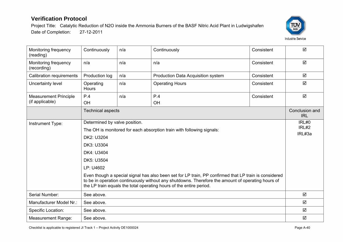
Verification Protocol Project Title: Catalytic Reduction of N2O inside the Ammonia Burners of the BASF Nitric Acid Plant in Ludwigshafen Date of Completion: 27-12-2011
Checklist is applicable to registered JI Track 1 – Project Activity DE1000024 Page A-40
Monitoring frequency (reading)
Continuously n/a Continuously Consistent
Monitoring frequency (recording)
n/a n/a n/a Consistent
Calibration requirements Production log n/a Production Data Acquisition system Consistent
Uncertainty level Operating Hours
n/a Operating Hours Consistent
Measurement Principle (if applicable)
P.4 OH
n/a P.4 OH
Consistent
Technical aspects Conclusion and IRL
Instrument Type: Determined by valve position.
The OH is monitored for each absorption train with following signals:
DK2: U3204
DK3: U3304
DK4: U3404
DK5: U3504
LP: U4602
Even though a special signal has also been set for LP train, PP confirmed that LP train is considered to be in operation continuously without any shutdowns. Therefore the amount of operating hours of the LP train equals the total operating hours of the entire period.
IRL#0 IRL#2
IRL#3a
Serial Number: See above.
Manufacturer Model Nr.: See above.
Specific Location: See above.
Measurement Range: See above.

Verification Protocol Project Title: Catalytic Reduction of N2O inside the Ammonia Burners of the BASF Nitric Acid Plant in Ludwigshafen Date of Completion: 27-12-2011
Checklist is applicable to registered JI Track 1 – Project Activity DE1000024 Page A-41
Gaps in operating time of instrument :
Period: no gaps during this monitoring period
Default value used: not applicable
Justification: not applicable
QA/QC aspects Conclusion and IRL
Source of data See above. Type: digital
Procedures:
Implementation of procedure:
Responsibility: JI Project Manager
Archiving of raw data and protection measures
Permanent data archiving of the main server D-EMS 2000 takes place on the monitoring system until the hard disc is full, minimum 10 years. Additionally, a copy of the new data is created and stored on the production network of the VM-Ware server. This external data back up is controlled every 24h; in case of failure the office for communication technology and IT-security will be notified by the monitoring software.
Data transfer and protec-tion of input data for cal-culations
The data is manually exported via csv-file from the DURAG system in the Excel calculation tool.
Quality of evidence Conclusion and IRL
Completeness of data The DURAG data was reviewed on the period and showed complete and credible data. Any devia-tion is described above in section “Gaps in operating time of instrument”.
Data verification Consistency of raw data with calculation tool: The raw data is found to be correctly transferred to the calculation tool.
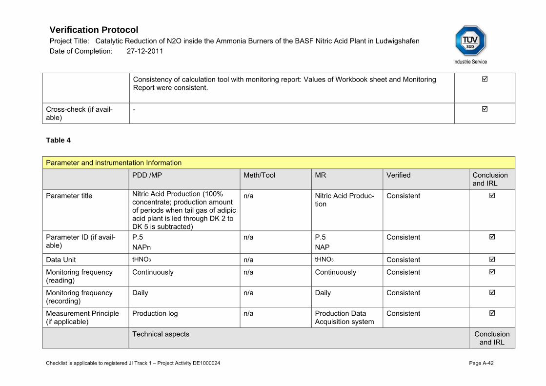
Verification Protocol Project Title: Catalytic Reduction of N2O inside the Ammonia Burners of the BASF Nitric Acid Plant in Ludwigshafen Date of Completion: 27-12-2011
Checklist is applicable to registered JI Track 1 – Project Activity DE1000024 Page A-42
Consistency of calculation tool with monitoring report: Values of Workbook sheet and Monitoring Report were consistent.
Cross-check (if avail-able)
-
Table 4
Parameter and instrumentation Information
PDD /MP Meth/Tool MR Verified Conclusion and IRL
Parameter title Nitric Acid Production (100% concentrate; production amount of periods when tail gas of adipic acid plant is led through DK 2 to DK 5 is subtracted)
n/a Nitric Acid Produc-tion
Consistent
Parameter ID (if avail-able)
P.5 NAPn
n/a P.5 NAP
Consistent
Data Unit tHNO3 n/a tHNO3 Consistent
Monitoring frequency (reading)
Continuously n/a Continuously Consistent
Monitoring frequency (recording)
Daily n/a Daily Consistent
Measurement Principle (if applicable)
Production log n/a Production Data Acquisition system
Consistent
Technical aspects Conclusion and IRL
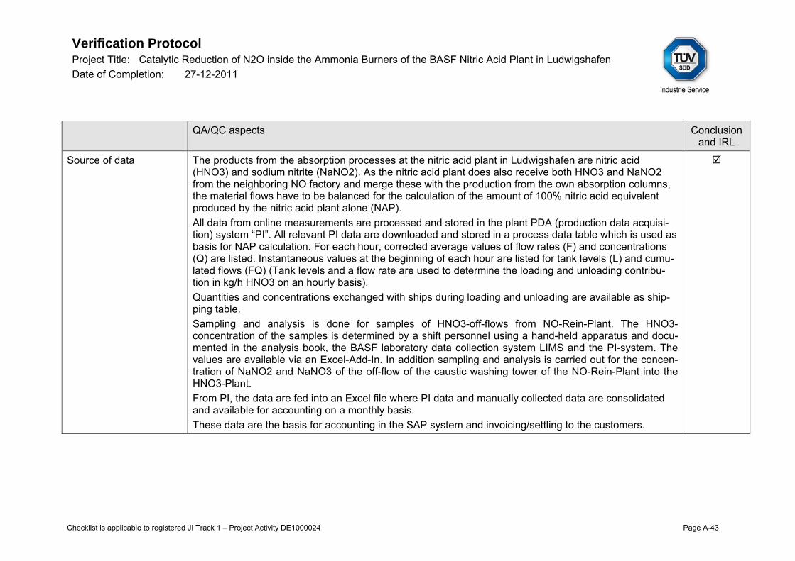
Verification Protocol Project Title: Catalytic Reduction of N2O inside the Ammonia Burners of the BASF Nitric Acid Plant in Ludwigshafen Date of Completion: 27-12-2011
Checklist is applicable to registered JI Track 1 – Project Activity DE1000024 Page A-43
QA/QC aspects Conclusion and IRL
Source of data The products from the absorption processes at the nitric acid plant in Ludwigshafen are nitric acid (HNO3) and sodium nitrite (NaNO2). As the nitric acid plant does also receive both HNO3 and NaNO2 from the neighboring NO factory and merge these with the production from the own absorption columns, the material flows have to be balanced for the calculation of the amount of 100% nitric acid equivalent produced by the nitric acid plant alone (NAP). All data from online measurements are processed and stored in the plant PDA (production data acquisi-tion) system “PI”. All relevant PI data are downloaded and stored in a process data table which is used as basis for NAP calculation. For each hour, corrected average values of flow rates (F) and concentrations (Q) are listed. Instantaneous values at the beginning of each hour are listed for tank levels (L) and cumu-lated flows (FQ) (Tank levels and a flow rate are used to determine the loading and unloading contribu-tion in kg/h HNO3 on an hourly basis). Quantities and concentrations exchanged with ships during loading and unloading are available as ship-ping table. Sampling and analysis is done for samples of HNO3-off-flows from NO-Rein-Plant. The HNO3-concentration of the samples is determined by a shift personnel using a hand-held apparatus and docu-mented in the analysis book, the BASF laboratory data collection system LIMS and the PI-system. The values are available via an Excel-Add-In. In addition sampling and analysis is carried out for the concen-tration of NaNO2 and NaNO3 of the off-flow of the caustic washing tower of the NO-Rein-Plant into the HNO3-Plant. From PI, the data are fed into an Excel file where PI data and manually collected data are consolidated and available for accounting on a monthly basis. These data are the basis for accounting in the SAP system and invoicing/settling to the customers.

Verification Protocol Project Title: Catalytic Reduction of N2O inside the Ammonia Burners of the BASF Nitric Acid Plant in Ludwigshafen Date of Completion: 27-12-2011
Checklist is applicable to registered JI Track 1 – Project Activity DE1000024 Page A-44
As per revised Monitoring Plan the NAP is calculating acc. to formula: NAP = (E - A ) + (C - B ) - D - F

Verification Protocol Project Title: Catalytic Reduction of N2O inside the Ammonia Burners of the BASF Nitric Acid Plant in Ludwigshafen Date of Completion: 27-12-2011
Checklist is applicable to registered JI Track 1 – Project Activity DE1000024 Page A-45
Where: NAPn HNO3 production of the nth monitoring period (tHNO3) En Total HNO3 supply to customers (comprises HNO3 from the NO plant and the HNO3 plant) (tHNO3) An HNO3 inflow from NO factory (tHNO3) Cn Total NaNO2 release (comprises NaNO2 from the NO plant and the HNO3 plant) (tHNO3) Bn NaNO2 inflow from NO factory (tHNO3) Dn HNO3 production of DK 1 (tHNO3) Fn HNO3 production of DK 2 to DK 5 in periods where adipic acid tail gas is led through DK 2 to DK 5 (tHNO3) Type: digital
Procedures: JI Manual Chapter 4- 5, Annexes 5.4.5. a-h, 5.5.1.a-e. IRL#5
Implementation of procedure: Reviewing the project documents it can be confirmed that procedures are implemented.
Responsibility: Paul Merschilz, a member of the plant staff, acts as maintenance manager for the process control equipment of the plant. Andreas Müller acts as his deputy. In the JI-project they are responsible for the installation and maintenance of the measuring equipment which is necessary for the determination of the NAP-value. Refractometer, titrator and UV VIS spectrometer are handled by members of the ana-lytical service CAA/Q (Mr. Höppchen, Mr. Hess, Mr. Elie). They are responsible for visual inspection, plausibility check of measured data and, if possible, troubleshooting. In case of malfunctions that cannot be repaired by CAA/Q and in case of annual or semi-annual equipment maintenance the department for process analytics GTF/EB in L426 is to be notified.
Archiving of raw data and protection measures
All actual data is transferred to the data acquisition system (PI System) where it is collected on 5 hard discs inside the PI-Server. Only in the case of more than 2 simultaneous hard disc failures data is lost inside the PI-Server. In addition every day a copy of the new daily data is created between 2 a.m. and 3 a.m. and stored at MES-Service-Centre L440 on a Backup-Server. In addition the daily data is archived on an additional Back-Up-Server. If the archive covers a time of 2 month the archive is transferred to long-time storage at BASF-IT-Services and a new archiving process is started. Raw data are archived at least 2 years after the last transfer of ERU’s. The results of manual concentration measurements are collected in the “Konzentrationsbuch”. The “Kon-

Verification Protocol Project Title: Catalytic Reduction of N2O inside the Ammonia Burners of the BASF Nitric Acid Plant in Ludwigshafen Date of Completion: 27-12-2011
Checklist is applicable to registered JI Track 1 – Project Activity DE1000024 Page A-46
zentrationsbuch” is stored in the control station in N420. After final determination of a data-set for a monitoring period the complete data will be stored electroni-cally (either as program file or as PDF-file) and as paper data for at least two years after allocation of cer-tificates.
Data transfer and pro-tection of input data for calculations
All data from online measurements are processed and stored in the plant PDA (production data acquisi-tion) system “PI”. From PI, the data are fed into an Excel file where PI data and manually collected data are consolidated and available for accounting on a monthly basis. Furthermore, tables with data not available in PI are taken into account. Additional replacement values are specified for various tags and time spans. These overwrite the previously determined data. These data are the basis for accounting in the SAP system and invoicing/settling to the customers. Daily results are obtained by repeating the hourly calculations. Calculations for an entire monitoring pe-riod are found by repeating the daily calculations. After final determination of calculation procedures Data are stored in Excel-Files which are protected against unwanted changes by “writing protection”. In addition the final version of an excel file will be printed as PDF-File.
Quality of evidence Conclusion and IRL
Completeness of data Corrective Action Request No.4 During the on-site visit project proponents presented to the assessment team the cross- check of calcu-lated NAP from the nitrogen mass balance which takes into account all N flows within the project bound-ary. Furthermore the cross- check against the SAP billing has been conducted. Those cross- checks have to be provided to the assessment team incl. a description. In case of differences and inconsisten-cies pls. provide a clarification and respective evidence. The approach of using any NAP default values has been mentioned in the JI Manual. However the overview of the NAP default values is still missing. Thus the NAP calculation tool has to be amended by summarizing the default values and identifying the respective criteria in order to provide a clear overview. The result of the N balance and SAP cross- check has to be reported in the MR or/and JI Manual. In doing so please update the information provided in chapters 7.2.3, 7.2.6, 7.2.7 and Annex 5.5.8 of JI Manual.
Raw data were reviewed which show complete and credible data. Any deviation is described above in
CAR IRL#3b
IRL#8

Verification Protocol Project Title: Catalytic Reduction of N2O inside the Ammonia Burners of the BASF Nitric Acid Plant in Ludwigshafen Date of Completion: 27-12-2011
Checklist is applicable to registered JI Track 1 – Project Activity DE1000024 Page A-47
section “Gaps in operating time of instrument”.
Data verification Consistency of raw data with calculation tool: Data of calculation tool were cross- checked against SAP data.
Consistency of calculation tool with monitoring report: See CAR above. CAR
Cross-check (if avail-able)
In addition, the nitrogen balance (all inflows vs. all outflows) is determined for plausibility check. An over-view shows the hourly results. However see CAR above.
CAR
2.3. Parameters measured through sampling
Not applicable
2.4. Parameters obtained through external sources and accounting data Table 1
External sources and accounting information
PDD Meth/Tool MR Verified Conclusion and IRL
Parameter title Emission limit set by incoming policies or regulations
n/a Emission limit set by incoming poli-cies or regulations
consistent
Parameter ID (if avail-able)
EFreg n/a EFreg consistent
Data Unit kgN2O/tHNO3 n/a kgN2O/tHNO3 consistent
Technical aspects Conclusion
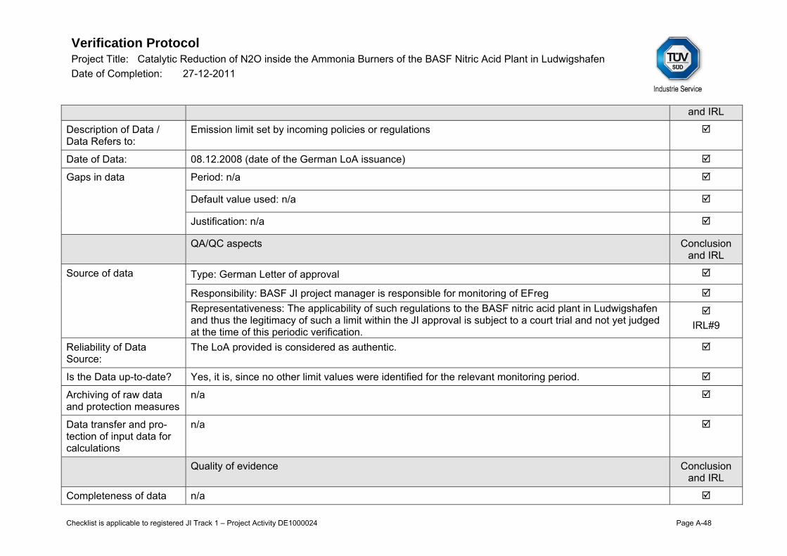
Verification Protocol Project Title: Catalytic Reduction of N2O inside the Ammonia Burners of the BASF Nitric Acid Plant in Ludwigshafen Date of Completion: 27-12-2011
Checklist is applicable to registered JI Track 1 – Project Activity DE1000024 Page A-48
and IRL
Description of Data / Data Refers to:
Emission limit set by incoming policies or regulations
Date of Data: 08.12.2008 (date of the German LoA issuance)
Gaps in data Period: n/a
Default value used: n/a
Justification: n/a
QA/QC aspects Conclusion and IRL
Source of data Type: German Letter of approval
Responsibility: BASF JI project manager is responsible for monitoring of EFreg Representativeness: The applicability of such regulations to the BASF nitric acid plant in Ludwigshafen and thus the legitimacy of such a limit within the JI approval is subject to a court trial and not yet judged at the time of this periodic verification.
IRL#9
Reliability of Data Source:
The LoA provided is considered as authentic.
Is the Data up-to-date? Yes, it is, since no other limit values were identified for the relevant monitoring period.
Archiving of raw data and protection measures
n/a
Data transfer and pro-tection of input data for calculations
n/a
Quality of evidence Conclusion and IRL
Completeness of data n/a

Verification Protocol Project Title: Catalytic Reduction of N2O inside the Ammonia Burners of the BASF Nitric Acid Plant in Ludwigshafen Date of Completion: 27-12-2011
Checklist is applicable to registered JI Track 1 – Project Activity DE1000024 Page A-49
Data verification Consistency of raw data with calculation tool: see below.
Consistency of calculation tool with monitoring report: The MR demonstrates 2 alternatives for the amount emission reductions based on the determined baseline emission factor of 4,5 kgN2O/tHNO3 and regulatory baseline emission factor stated in the LoA issued by the DEHSt on 8.12.2008 (2,5 kgN2O/tHNO3). DEHSt agreed on this as the legitimacy of such a limit within the JI approval is subject to a court trial and not yet judged at the time of this periodic veri-fication.
IRL#2 IRL#3 IRL#9
Cross-check (if avail-able)
n/a

Verification Protocol Project Title: Catalytic Reduction of N2O inside the Ammonia Burners of the BASF Nitric Acid Plant in Ludwigshafen Date of Completion: 27-12-2011
Checklist is applicable to registered JI Track 1 – Project Activity DE1000024 Page A-50
3. Data Processing and ER calculation
Description of data processing from transferred data to final results in the calculation tool
Step Description Conclusion and IRL
Consistency All abbreviations and units are consistent with the revised Monitoring Plan and traceable to the raw data.
Calculation Tool de-scription
The final calculation tool is clearly described and transparent and equipped with issuing date and revi-sion number. All formulae, intermediate steps and constants are described transparently including correct units and in compliance with the revised MP.
IRL#3a
Elimination of not plausible data (if ap-plicable)
Validity of data is defined as more than 2/3 of values per hour are available. Default values are applied for not plausible data/obsolete data. Procedures are implemented for data evaluation and default data setting and calculation, see also FAR 1. Details are described in JI Manual Chapters 6 and 7. This procedure was reviewed by the audit team and found to be conservative.
FAR
Transformation from useable data to input data for further calcu-lation (if applicable)
Measurement instrument data is derived from DURAG system. DURAG system provides hourly average values which are the basis for emission reduction calculation which are calculated in the Excel calculation tool on hourly basis.
Ex-ante data Following ex-ante data used in the calculation tool are in compliance with the PDD: The emission factor baseline was fixed to the conservative IPPC value of 4,5 kgN2O/tHNO3 at the de-termination stage. However the MR demonstrates 2 alternatives for the amount emission reductions based on the determined baseline emission factor of 4,5 kgN2O/tHNO3 and regulatory baseline emis-sion factor stated in the LoA issued by the German DFP DEHSt on 8.12.2008 (2,5 kgN2O/tHNO3). DEHSt agreed on this as the legitimacy of such a limit within the JI approval is subject to a court trial and not yet judged at the time of the second periodic verification. The same values are applied in the emission reduction calculation tool.
IRL#9

Verification Protocol Project Title: Catalytic Reduction of N2O inside the Ammonia Burners of the BASF Nitric Acid Plant in Ludwigshafen Date of Completion: 27-12-2011
Checklist is applicable to registered JI Track 1 – Project Activity DE1000024 Page A-51
Default parameter Following ex-ante data used in the calculation tool are in compliance with the PDD and revised MP: N2O Global Warming Potential GWP_N2O=310
Formulae check The calculation for emission reduction in the Excel calculation tool is in compliance with the Monitoring Plan. Emission Reductions:
Baseline Emissions:
Project Emissions:
Total N2O emissions of monitoring period n are the sum of the emissions of the single production lines:
In order to take into account periods when DK 2 to DK 5 are fed by tail gas from the neighboring adipic acid plant and with this excluded from the project boundaries of this project, N2O emissions from DK 2 to DK 5 during these periods have are deducted from the total:
From the project emissions (FPEn) and the accordant nitric acid production (P.5) in the monitoring pe-riod, the specific project emission factor is calculated:

Verification Protocol Project Title: Catalytic Reduction of N2O inside the Ammonia Burners of the BASF Nitric Acid Plant in Ludwigshafen Date of Completion: 27-12-2011
Checklist is applicable to registered JI Track 1 – Project Activity DE1000024 Page A-52
Rounding functions Not applicable
Calculation tool changes and protec-tion measures
See CRs and CARs above. CR CAR
Reported data Corrective Action Request No.5 The figures of the MR are consistent with the figures of the calculation tool. However cross- checking the reported data with the daily events list, some inconsistencies were noticed: e.g. the daily event from 7.01.10 (Störung at F3225) was not considered in the calculation tool and hence no default values have been applied for F3225 for the respective hours; the daily event on 23.10.09 has been correctly consi-dered in the calculation tool, however not reported correctly in the daily event list. There have also some inconsistencies been traced between working sheets “Other DefValues” and “Calc” in the Excel Tool: the “Störung in F3225” is indicated in the comments to 26.07.10 8:00- 27.07.10 2:00, furthermore the correct default values are applied on the respective volume flow data. However the default value speci-fied in “Other DefValues” is for the concentration measurement. The same is for event at F3525 on 19.01.2011 9:00-16:00. The calculation tool has to be amended accordingly. The daily events list (Annex 5.6.1.1 of JI Manual) has to be amended by reporting the daily events (Sondersituationen) in complete manner. The revised docs have to be provided to the assessment team.
IRL#3a IRL#4
Verification Protocol Project Title: Catalytic Reduction of N2O inside the Ammonia Burners of the BASF Nitric Acid Plant in Ludwigshafen Date of Completion: 27-12-2011
Checklist is applicable to registered JI Track 1 – Project Activity DE1000024 Page A-53
4. Additional assessment
4.1. Internal Review
Description and performance of internal review
Description Conclusion and IRL
Procedure Daily quality meeting during the working week is part of the daily morning talk of the plant staff. Partici-pants are plant manager and JI-manager or his deputy, one member of process automation and proc-ess engineering. Topics are discussion of exceptional events in the decomposition units and generation of measures for open issues. An additional JI-meeting takes place three times a week (Mondays, Wednesdays and Fridays). Partici-pants are JI-manager Mr. Wölfert or his deputy Mr. Köllner and members of quality assurance group E-CAA/Q. Topics are N2O-trends evaluation, update of the maintenance schedule, logging of exceptional events in the decomposition units, JI-relevant changes of DCS (e.g. reconfiguration of DCS, changes of JI-relevant switching points in DCS). A JI protocol is completed at the end of the shift by the shift leader for the safeguarding of the correct functioning of the N2O analysis measurement and the NAP-relevant measurements of volume and con-centration. Here the correct state of all NAP-relevant measurements and N2O measurements are documented, which are then discussed at the daily quality meetings. The instruction manual for the shift is available which summarizes procedures in case of malfunctions and maintenance requirements and describes documentation in JI-protocol
Documentation N2O-trends evaluation, JI protocol, daily events list are available as evidence for this procedure. See CAR in section 3 above.
CAR IRL#4
Responsibilities See above.
4.2. Peculiarities
Please refer to Chapter 1.1 “Remarks to Special Operational Status During the Verification Period”.

Verification Protocol Project Title: Catalytic Reduction of N2O inside the Ammonia Burners of the BASF Nitric Acid Plant in Ludwigshafen Date of Completion: 27-12-2011
Checklist is applicable to registered JI Track 1 – Project Activity DE1000024 Page A-54
4.3. Further additional requirements Not applicable
4.4. Data Reporting
Description of the Monitoring Report
Comments and Results Conclusion and IRL
Compliance with UNFCCC regulations
Not applicable as JI track 1
Completeness and Transparency
Clarification Request No. 6 The current MR reports on refilling of the secondary catalyst in furnaces S6, S4 and S2 in this monitor-ing period, however during the on-site inspection the PP confirmed that the secondary catalyst was also refilled in the furnace S1. The MR has to be revised accordingly. The respective evidence for the cata-lyst refilling has to be provided to the assessment team.
The Monitoring Report reports the monitoring parameters for the required monitoring recording fre-quency showing the compliance with the monitoring plan. For some values reference is given to the Excel Calculation Tool but general information on the parameters is reported in the MR. The MR provides the comparison of PDD’s ER estimates to situation of monitoring period. It is shown that due to the economic crisis the DK4 was out of operation during this monitoring period and less nitric acid has been produced. Thus the lower amount of emission reductions as reported for 2009-2010 cor-responds with the lower HNO3 production figures. For the first 2 months of 2011 the lower HNO3 production, but higher emission reductions are reported. The reason is the improved operating and handling of the furnaces and secondary catalyst. The production cap has not been exceeded and therefore no adjustment of the emission reduction cal-culation is necessary.
CR IRL#7
Correctness Values from the assessed final calculation tool and other relevant sources were correctly transferred to the final Monitoring Report.
IRL#9
Verification Protocol Project Title: Catalytic Reduction of N2O inside the Ammonia Burners of the BASF Nitric Acid Plant in Ludwigshafen Date of Completion: 27-12-2011
Checklist is applicable to registered JI Track 1 – Project Activity DE1000024 Page A-55
5. Compilation and Resolutions of CARs, CRs and FARs
Corrective Action Requests by audit team
Comments and Results Ref Conclusion and IRL
Issue Corrective Action Request No.1 The pipes connecting the ADS plant with DK3-5 have been removed which is confirmed by the evidence provided in Annex 15 of JI Manual. Thus please adapt the information given in the revised MP, e.g. figure 1.
Chapter 2.1
This finding is closed.
IRL#6
Response Figure 1 of the monitoring plan is amended according to the new plant configuration. The pipes connecting the ADS plant with DK3 may be installed again in the future.
Assessment The revised MP has been assessed by the audit team. The figure 1 was found to be adapted according to the current plant situation.
Issue Corrective Action Request No.2 The Annex 5.1.5 of JI Manual provides an overview on the QAL 2 and AST tests conducted and reports whether the respective regression coefficients have been applied in the DURAG emission calculator. The PP is requested to update that overview taking into account the last QAL2s and ASTs performed. The information reported shall be consistent throughout the project documentation (MR, JI Manual, MP). Updated overview has to be provided to the audit team. Furthermore please provide the updated DURAG parameter list.
Chapter 2.2 Table 1
This finding is closed.
IRL#6
Response 1 The overview of QAL2 and AST dates and parameters is updated and takes into account the last QAL2 and AST of each metering device (see attached file „AST-QAL2-Uebersicht_2011-05-31.xls“). The implemented DURAG parameters are also given in this file.
Assessment 1 The assessment team checked the revised Annex 5.1.5 of JI Manual v. 2.1. The overview of QAL2 and AST is updated and takes into account the last QAL2 and AST of each metering

Verification Protocol Project Title: Catalytic Reduction of N2O inside the Ammonia Burners of the BASF Nitric Acid Plant in Ludwigshafen Date of Completion: 27-12-2011
Checklist is applicable to registered JI Track 1 – Project Activity DE1000024 Page A-56
device.
However the information reported in the MR is not consistent with that list, e.g. the dates of the QAL2 performance seem to differ among those documents. Please clarify this inconsis-tency and correct the dates if necessary. And please provide the updated DURAG parame-ter list.
Response 2 The dates of QAL2 and AST are corrected in the revised monitoring report and should be consistent with the Excel file „AST-QAL2-Uebersicht_2011-05-31.xls“ in annex 5.1.5 of the JI manual.
Assessment 2 The revised MR has been cross- checked with the AST-QAL2-Uebersicht_2011-05-31.xls“ (annex 5.1.5 of the JI Manual). The dates of QAL2 and AST conducted are now consistent.
Issue Corrective Action Request No.3 As already mentioned above, there is a certain overlapping between the project in hands and another JI project taking place at the BASF adipic acid plant. Verifying the DURAG vo-lume flow data sets for both project a difference of around 17,6% has been traced between the data obtained at DK2 in the HNO3 project and those obtained at the DK2 in the ADS project. The PP is requested to clarify this phenomenon, evaluate its impact on the both projects and consider it taking into account conservative bias.
Chapter 2.2 Table 2
FAR1
IRL#3c
Response DK1 and DK2 can be locked against each other for maintenance at one of the two respec-tive DKs. During these periods only one of the DKs is running, while the other one is shut down and depressurized. DURAG raw data available for the ADS project showed some vo-lume flow values even in the periods when the DKs are shutdown and depressurized. The possible sources of those volume flows are described in the ADS project documentation. These volume flows have not been considered by the established monitoring plan so far. In order to consider these volume flows and possible N2O emissions for the calculation of the emissions reductions in the future a second DURAG run is applied considering N2O emis-sions and volume flows of DK1 and DK2 in the named situations.
The difference of around 17,6% between the data obtained at DK2 in the HNO3 project and those obtained at the DK2 in the ADS project are caused by following phenomenon:

Verification Protocol Project Title: Catalytic Reduction of N2O inside the Ammonia Burners of the BASF Nitric Acid Plant in Ludwigshafen Date of Completion: 27-12-2011
Checklist is applicable to registered JI Track 1 – Project Activity DE1000024 Page A-57
Data series PROJC_2 column D of worksheet “DURAGdata_2ndrun” in file “Calcula-tion_2ndPeriod_JI-ADS_rev2.schreibgeschützt.xls” of the ADS project are based on old/wrong calibration parameters for measuring point F3225.
On 13 January 2011 DURAG was requested by BASF (in person of Andrea Schmidt) to cor-rect the calibration parameters for measuring point F3225. Following this request, volume flow of DK2 (so-called first run) was recalculated. The parameter correction was imple-mented on 14 January 2011. The difference between old/wrong and revised/correct volume flow values is about 17.6% (see attached file “Background wrong ProjectCalc 2.xls”).
The mistake in file “Calculation_2ndPeriod_JI-ADS_rev2.schreibgeschützt.xls” of the ADS project occurred as project team forgot to download corrected volume flows of DK2 also in worksheet “DURAGdata_2ndrun” of the ADS Excel calculation tool. That means a wrong emission reduction calculation in the ADS project. The HNO3 project is not affected by the wrong calibration parameters. The calculation of emission reductions in the HNO3 project is correct and consistent with the intermediately corrected calculation in the ADS project.
In the future such a mistake shall be excluded via improved cross- checking methods. In general a comparison of average values from first and second run shall be implemented.
Assessment The assessment team reviewed the following documents provided by the PP (IRL#3 and #2 of the Final Verification Report No. 600500552 for the second periodic verification of the JI Track 1 project “Redundant catalytic decomposition of residual nitrous oxide (N2O) from the BASF adipic acid plant in Ludwigshafen” UNFCCC DE-1000018, hereinafter referred as ADS project) in context of the 2nd verification of the ADS project:
- Background wrong ProjectCalc 2.xls - Calculation_2ndPeriod_JI-ADS_rev3.xls - Emissionen_DK2_2ndrun-corr.xls
The explanation of the mistake given is plausible and is confirmed by the example calcula-tion presented in “Background wrong ProjectCalc 2.xls”. The correct DURAG 2nd run vo-lume flow data from DK2 for ADS project have been cross- checked against the correspond-ing flow data from the HNO3 project, no significant difference was found. The emission re-ductions of ADS project have been re-calculated using the correct data; the results have
Verification Protocol Project Title: Catalytic Reduction of N2O inside the Ammonia Burners of the BASF Nitric Acid Plant in Ludwigshafen Date of Completion: 27-12-2011
Checklist is applicable to registered JI Track 1 – Project Activity DE1000024 Page A-58
been reported in the revised MR for ADS.
It is confirmed that the project at hand is not affected by the wrong calibration parameters. Thus no correction was requested to be made in the calculation of emission reductions of this project.
However the internal data review conducted by the BASF project management has to be improved in order to avoid any inconsistencies in the future data reporting and calculation of emission reductions, pls. refer to FAR#1.
Issue Corrective Action Request No.4 During the on-site visit project proponents presented to the assessment team the cross- check of calculated NAP from the nitrogen mass balance which takes into account all N flows within the project boundary. Furthermore the cross- check against the SAP billing has been conducted. Those cross- checks have to be provided to the assessment team incl. a description. In case of differences and inconsistencies pls. provide a clarification and re-spective evidence. The approach of using any NAP default values has been mentioned in the JI Manual. However the overview of the NAP default values is still missing. Thus the NAP calculation tool has to be amended by summarizing the default values and identifying the respective criteria in order to provide a clear overview. The result of the N balance and SAP cross- check has to be reported in the MR or/and JI Manual. In doing so please update the information provided in chapters 7.2.3, 7.2.6, 7.2.7 and Annex 5.5.8 of JI Manual.
Chapter 2.2 Table 3
This finding is closed.
IRL#3b
IRL#8
Response 1 The named cross- checks are given in attached Excel file “2011_06_07_SAP-Abgleich-rev2-woelfert.xls”.
An overview of all defined and used default values for NAP determination are given in the NAP Tool “2011_05_16_HNO3-Bilanz_Rev-3.xls” (see file “Appendix FAR1.zip”). With this document the project specific default values are documented in a transparent way.
The results of the N balance and SAP cross- check is reported in the above named chapters of the JI Manual. The values named in the specific chapters are amended if necessary.
Assessment 1 In the abovementioned sections of JI Manual v. 2.1 the 8% difference between the SAP’s NAP figure and balanced NAP figure is reported. However the SAP Abgleich – Excel sheet

Verification Protocol Project Title: Catalytic Reduction of N2O inside the Ammonia Burners of the BASF Nitric Acid Plant in Ludwigshafen Date of Completion: 27-12-2011
Checklist is applicable to registered JI Track 1 – Project Activity DE1000024 Page A-59
shows the 0,08% difference, the average balance error is around 10% (2011_06_06_NAP results.xls).
The PP is requested to report the results of the NAP cross- checks in transparent manner referring to the respective analysis documents. The daily results of the N balance (MP1_d_C2.xls, MP2_h_C2.xls, MP3_h_C2.xls, MP4_d_C2.xls, MP5_h_C2.xls, MP6_d_C2.xls) should be provided in order to justify the balance error figures presented in 2011_06_06_NAP results.xls
Response 2 In Section 4.6 of JI Manual now a value of 10% is reported for the error of metered Nitrogen inflow into the nitric acid plant and metered outflow of Nitrogen based products, correspond-ing to 2011_06_06_NAPresults.xls.
In 2011_06_07_SAP-Abgleich-rev2-woelfert.xls an error of 0.08% has been reported. This is a cross-check which allows to compare amounts of product in commercial SAP-billing and NAP-calculation. As both numbers are based on identical metering points ideally those numbers should be identical. However due to different approaches of data handling and in case of downtime of metering equipment slight differences are normal. The hourly and daily results of the N balance are provided to the assessment team attached in file “CAR-4.zip”.
Assessment 2 The audit team checked the following documents provided by the PP:
- The daily results of the N balance (MP1_d_C2.xls, MP2_h_C2.xls, MP3_h_C2.xls, MP4_d_C2.xls, MP5_h_C2.xls, MP6_d_C2.xls); - 2011_06_06_NAP results.xls - 2011_06_07_SAP-Abgleich-rev2-woelfert.xls
The nitrogen mass balance which takes into account all N flows within the project boundary was reviewed by the audit team comparing with the raw data taken from the PIMS. The av-erage deviation was found to be 10% between the nitrogen flow into and out of the balance boundaries. Taking into account the yield loses of 3,5-4,5% caused by the incomplete NH3 oxidation and incomplete NO2 absorption, the balance error is around 6%, that is conserva-tive (more nitrogen input than output). The calculated NAP was cross- checked with the raw production data and SAP billing. It was found that the deviation between the calculated NAP and SAP billing is 0,08%.

Verification Protocol Project Title: Catalytic Reduction of N2O inside the Ammonia Burners of the BASF Nitric Acid Plant in Ludwigshafen Date of Completion: 27-12-2011
Checklist is applicable to registered JI Track 1 – Project Activity DE1000024 Page A-60
Issue Corrective Action Request No.5 The figures of the MR are consistent with the figures of the calculation tool. However cross- checking the reported data with the daily events list, some inconsistencies were noticed: e.g. the daily event from 7.01.10 (Störung at F3225) was not considered in the calculation tool and hence no default values have been applied for F3225 for the respective hours; the daily event on 23.10.09 has been correctly considered in the calculation tool, however not re-ported correctly in the daily event list. There have also some inconsistencies been traced between working sheets “Other DefValues” and “Calc” in the Excel Tool: the “Störung in F3225” is indicated in the comments to 26.07.10 8:00- 27.07.10 2:00, furthermore the cor-rect default values are applied on the respective volume flow data. However the default val-ue specified in “Other DefValues” is for the concentration measurement. The same is for event at F3525 on 19.01.2011 9:00-16:00. The calculation tool has to be amended accordingly. The daily events list (Annex 5.6.1.1 of JI Manual) has to be amended by reporting the daily events (Sondersituationen) in complete manner. The revised docs have to be provided to the assessment team.
Chapter 3 This finding is closed. IRL#2
IRL#3a
IRL#4
Response 1 The calculation tool and the daily events list (Annex 5.6.1.1 of JI Manual) are amended and report the daily events in complete and consistent manner. The revised docs are provided to the assessment team.
Assessment 1 The assessment team checked the revised Excel calculation tool and Annex 5.6.1.1 of JI Manual v. 2.1. The cross- check of these two documents does not show any inconsisten-cies. The requested corrections have been conducted by the PPs. The Excel Tool and daily events list report the daily events in complete and consistent manner now.
The revised MR was assessed by the audit team. The reported amount of emission reduc-tions has been revised taking into account corrected calculations. However the total sum of the emission reductions calculated with BL EF = 4,5 does not seem correct when adding the ERs figures for the single reported periods. Pls. clarify and correct. Furthermore pls. report the annual total ERs figures in revised MR.
Response 2 The calculated emission reductions are corrected.

Verification Protocol Project Title: Catalytic Reduction of N2O inside the Ammonia Burners of the BASF Nitric Acid Plant in Ludwigshafen Date of Completion: 27-12-2011
Checklist is applicable to registered JI Track 1 – Project Activity DE1000024 Page A-61
Assessment 2 The revised MR has been reviewed by the assessment team. The front page of the revised MR now reports the annual ERs within the 2nd monitoring period. Furthermore the total sum of the emission reductions calculated with BL EF = 4,5 is now correct when adding the ERs figures for the single reported periods. Verifier confirms that the total amount of emission reductions reported is in compliance with the values calculated in the Excel calculation tool.
Clarification Requests by audit team
Comments and Results Ref Conclusion and IRL
Issue Clarification Request No. 1 The PP is requested to confirm the validity of the obtained EFNO-pure = 4,35 kg N2O per ton of NAP for the relevant monitoring period.
Chapter 1.1
This issue is closed.
IRL#3a Response The validity of the obtained obtained EFNO-pure = 4,35 kg N2O per ton of NAP for the rele-
vant monitoring period can be confirmed by the PP. For the upcoming monitoring periods this factor will not play any role any longer because of the baseline factor of 2,5 kg N2O per ton of NAP.
Assessment The assessment team checked JI Manual v. 2.1 with the special focus on chapter 4.5 and Annex 4.5. Due to the fact, that EFNO-pure was calculated from N2O data obtained in the pe-riod from 2005 to 2010, its validity for this monitoring period can be confirmed.
After October 2010 the EFNO-pure is not used for correction of NAP any longer, since the baseline emission factor of 2,5 kgN2O/tHNO3 is applied, which is lower than EFNO-pure .
Issue Clarification Request No. 2 The PP is requested to clarify the necessary frequency of the DURAG loop check (e.g. sup-plier recommendations) to be conducted.
Chapter 2.2 Table 1
FAR2
IRL#6
IRL#7a Response There is no supplier information available with respect to loop check frequency. The Euro-
pean DIN EN 14181 excludes the interconnection of the emission metering equipment and

Verification Protocol Project Title: Catalytic Reduction of N2O inside the Ammonia Burners of the BASF Nitric Acid Plant in Ludwigshafen Date of Completion: 27-12-2011
Checklist is applicable to registered JI Track 1 – Project Activity DE1000024 Page A-62
the emission calculator. Therefore reference is given to the German VDI 3950, chapter 8.1 “Functional test” (see file “Appendix CR2.zip”). AST and loop check is done once per year as part of AST or QAL2.
IRL#9
Assessment The PP’s response inclusive the German VDI 3950 chapter 8.1 has been checked by the audit team. It was found reasonable to conduct the loop check once per year as part of the AST or QAL2. The last loop check was conducted in July 2010, what is confirmed by the N2O analyzers loop check protocol provided in Annex 3.5 of JI Manual..
The PP is requested to amend the chapter 3.5 of the JI Manual by including this information, pls. refer to FAR#2.
Issue Clarification Request No. 3 According to the EN 14181 applied the validity of the calibration range determined during the QAL 2 has to be observed by the operator. Therefore please include the EN 14181 con-formity test for the relevant monitoring period into the JI Manual (e.g. as an Annex). The revised JI Manual should be provided to the assessment team.
Chapter 2.2 Table 1
FAR3
IRL#6
Response The conformity test for the current monitoring period is added to annex 5.4.7 of the JI Man-ual. The original Excel file “ConformityTest_N2O Analyzers_EN14181_091001-110228.xls” is also provided to the assessment team attached to the verification protocol.
Assessment The conformity test for the current monitoring period presented in the Excel file “Con-formityTest_N2O Analyzers_EN14181_091001-110228.xls” has been assessed by the audit team. The results of this evaluation confirm the validity of the valid calibration range. However checking the Annex 5.4.7 the above mentioned Excel file was not found, it was found finally in Annex 5.3.7 of JI Manual v. 2.1. The PP is requested to improve the link between the MP, MR and JI Manual by providing correct reference in transparent manner and by using the same wording and terms when describing any project specific situation. Furthermore the link between the JI Manual and its Annexes has to be improved. Pls. refer to FAR#3.

Verification Protocol Project Title: Catalytic Reduction of N2O inside the Ammonia Burners of the BASF Nitric Acid Plant in Ludwigshafen Date of Completion: 27-12-2011
Checklist is applicable to registered JI Track 1 – Project Activity DE1000024 Page A-63
Issue Clarification Request No. 4 The real time data check conducted by the auditors during the physical site inspection did not show the credible and consistent data: e.g. the immediately measured values at Q3325 did not comply with the respective values registered in the PI system and DURAG system. The PP is requested to clarify the reason for this difference as DURAG system is a source of the hourly raw data used for the ER calculation. Moreover the correctness and reliability of the DURAG data provided for the relevant monitoring period must be confirmed.
Chapter 2.2 Table 1
This finding is closed.
IRL#7a
IRL#7b
Response Real time data check involved Q3315. Different “ppm” readings were observed. Reason for this has been different parameter sets for three different modes used: ProjectCalc, Project-Line, and CDM_JI. The ProjectCalc mode is correctly parametrised, and this mode is the only important mode and relevant for emission reduction calculation. The other modes are used for display purpose only, and their parameters were partly out-dated, which created some confusion during on-site visit. The parameters of the ProjectLine, and CDM_JI modes will be up-dated to avoid confusion during future inspection. See further details in file “Appendix CR4.zip”.
Assessment The real time data check at the metering point Q3115 was repeated by the PP. The as-sessment team reviewed the following documents provided:
- screen shot DK3-N2O-Analyser cross-check at 2011-06-03 14:34
- Durag-Screens-JI-HNO3-BASF-Lu-3011-06-03.pdf
- D-ER500 Parameterptokoll for CDM_JI_3
- D-ER500 Parameterptokoll for ProjLine
- QAL2 report_BASF_DK3-plant_2010 23
- D-ER500 Parameterptokoll for ProjCalc (status 14.09.2010 and 04.05.2011)
- PI trend PI-JI-HNO3-BASF-Lu-2011-06-03
- Analysis cross-check-DK3-rev0.xls
It has been confirmed that the ProjCalc mode, serving as a source for the data used in the ER calculation, and the ProjLine mode, which is used for displaying in DURAG immediately measured values are correctly parameterized with the valid regression parameters. And

Verification Protocol Project Title: Catalytic Reduction of N2O inside the Ammonia Burners of the BASF Nitric Acid Plant in Ludwigshafen Date of Completion: 27-12-2011
Checklist is applicable to registered JI Track 1 – Project Activity DE1000024 Page A-64
hence provide the correct and credible data.
The CDM_JI mode is still based on the old (invalid) regression parameters. Due to this fact, the values immediately measured at Q3315 during the on-site inspection did not comply with the respective values registered in the PI system and displayed in DURAG CDM_JI mode. This is confirmed by analysis “cross-check-DK3-rev0.xls”. As CDM_JI mode is only used for DCS purposes, it is not affecting the raw data in this JI project.
Issue Clarification Request No. 5 During the physical plant inspection the maintenance plan has been presented to the as-sessment team. The auditors cross- checked the plan with the original maintenance certifi-cates and records, and can confirm that the measuring devices installed have been main-tained properly and in time. However please amend the maintenance plan by including the LP DeNOx bypass valves and respective maintenance dates. The revised maintenance plan has to be submitted to the audit team. Please also provide copies of the maintenance certifi-cates cross- checked on-site (for F3225, T3235, P3225) and report on the last inspection of the bypass valves conducted in August 2010.
Chapter 2.2 Table 2
This finding is closed.
IRL#6
Response The LP DeNOx bypass valves are included in the maintenance schedule and include the respective maintenance dates. The revised maintenance plan is provided to the assessment team (see file “Appendix CR5.zip”) and is added to the JI manual (see annex 5.1.7).
The maintenance certificates cross-checked on-site are provided in file “Cross-Check-F3225-T3225-P3225-Maintenance-Certificates.pdf” (see file “Appendix CR5.zip”).
The last inspection of the LP DeNOx bypass valves was in September 2010 (see attached file “LP train_Check bypass valves September 2010.pdf”).
Assessment The revised maintenance plan and maintenance certificates have been assessed by the audit team. The maintenance plan now includes the LP DeNOx bypass valves. The last in-spection of those valves was conducted on 15-16.09.2010, the inspection protocol provided confirms the tightness of the DeNOx bypass valves. The verifier confirms that the measuring devices installed on-site have been maintained properly and in time.

Verification Protocol Project Title: Catalytic Reduction of N2O inside the Ammonia Burners of the BASF Nitric Acid Plant in Ludwigshafen Date of Completion: 27-12-2011
Checklist is applicable to registered JI Track 1 – Project Activity DE1000024 Page A-65
Issue Clarification Request No. 6 The current MR reports on refilling of the secondary catalyst in furnaces S6, S4 and S2 in this monitoring period, however during the on-site inspection the PP confirmed that the sec-ondary catalyst was also refilled in the furnace S1. The MR has to be revised accordingly. The respective evidence for the catalyst refilling has to be provided to the assessment team.
Chapter 4.4
This finding is closed.
IRL#7a
Response 1 The MR is revised as requested by TÜV Süd (see chapter 3 of the MR). The respective evi-dence for catalyst refilling is provided to the assessment team (file “BASF HNO3_Catalyst refilling_Monper2.pdf”).
Assessment 1 The revised MR and secondary catalyst refilling protocol have been checked by the as-sessment team. The MR now reports on refilling of the secondary catalyst. However cross- checking the reported dates of refilling against the dates given in the protocol the inconsis-tency was found in the refilling dates of S2 and S4. This should be clarified and corrected if necessary.
Response 2 The dates of catalyst refilling are corrected and should be consistent now. The correct dates of catalyst refilling are documented in attached Excel file “Annex 11_Kat-Einbau&Anfahrzeiten_rev7.xls”. The wrong date of furnace S4 is corrected to 02.02.2011.
Assessment 2 The revised MR and Annex 11_Kat-Einbau&Anfahrzeiten_rev7.xls have been reviewed by the assessment team. The dates of the secondary catalyst refilling are now correctly re-ported in the revised MR.
Issue Additional Request No. 1
The monitoring plan has to be amended by including a statement on whether the ASTs were conducted within the frequency required by the registered PDD and revised Monitoring Plan (see chapter 2 p. 4 of the MR).
This finding is closed.
IRL#2
IRL#6
Response A statement is added in chapter 2 “Repeating of the Annual Surveillance Test (AST)”.
Assessment TÜV SÜD assessment team checked the revised MR. The statement on ASTs conducted was found to have been included.
Verification Protocol Project Title: Catalytic Reduction of N2O inside the Ammonia Burners of the BASF Nitric Acid Plant in Ludwigshafen Date of Completion: 27-12-2011
Checklist is applicable to registered JI Track 1 – Project Activity DE1000024 Page A-66
Forward Action Requests by audit team
Comments and Results Ref Conclusion and IRL
Issue Forward Action Request No. 1
The internal data review conducted by the BASF project management has to be improved in order to avoid any inconsistencies in the future data reporting and calculation of emission reductions (see comments to CAR3).
Chapter 2.2 Table 1
FAR1
Response The project manager has already established some cross checks to avoid any inconsisten-cies in the future data reporting and calculation of emission reductions. The cross checks can be proved by the assessment team if necessary.
Assessment The additional internal data review and its implementation have to be verified at the next periodic verification.
Issue Forward Action Request No. 2 Taking into account German VDI 3950 chapter 8.1 it is correct to conduct the loop check once per year as part of the AST or QAL2. The PP is requested to amend the chapter 3.5 of the JI Manual by including this information.
Chapter 2.2 Table 1
FAR2
Response The JI manual, chapter 3.5 is amended by the information about yearly loop check accord-ing to German VDI 3950. Extract from German VDI 3950 is documented in annex 3.5 of the JI manual.
Assessment The revised JI Manual has to be verified at the next periodic verification.
Issue Forward Action Request No. 3 The PP is requested to improve the link between the MP, MR and JI Manual by providing correct reference in transparent manner and by using the same wording and terms when describing any project specific situation. Furthermore the link between the JI Manual and its
Chapter 2.2 Table 1
FAR3

Verification Protocol Project Title: Catalytic Reduction of N2O inside the Ammonia Burners of the BASF Nitric Acid Plant in Ludwigshafen Date of Completion: 27-12-2011
Checklist is applicable to registered JI Track 1 – Project Activity DE1000024 Page A-67
Annexes has to be improved.
Response The heading of chapter 6.1.1 and 6.1.2 are amended in order to document the link between Monplan and JI manual. The wording of JI Manual and Monplan will be amended, if the revi-sion of the Monplan is necessary.
Assessment The revised JI Manual has to be verified at the next periodic verification.

PERIODIC VERIFICATION “Catalytic Reduction of N2O inside the Ammonia Burners of the BASF Nitric Acid Plant in Ludwigshafen”
Annex 2: Information Reference List
Final
Report
27-12-2011
Periodic Verification of the JI track 1 Project:
“Catalytic Reduction of N2O inside the Ammonia Burners of the BASF Nitric Acid Plant in Ludwigshafen”
Information Reference List
Page 1 of 10
TÜV SÜD INDUSTRIE SERVICE GMBH
Ref.
No. Title/Type of Document. Publication place
0
Project Documents
- Final PDD for “Catalytic Reduction of N2O inside the Ammonia Burners of the BASF Nitric Acid Plant in Ludwigshafen”, v. 02
- Determination Report No. 1106682 for JI track 1 project “Catalytic Reduction of N2O inside the Ammonia Burners of the BASF Nitric Acid
Plant in Ludwigshafen” issued by TÜV SÜD, dated June 9th, 2008
- Approved baseline and monitoring methodology AM0034 v. 3
- Initial Periodic Verification Reports
- Revised Monitoring Plan – “Catalytic Reduction of N2O inside the Ammonia Burners of the BASF Nitric Acid Plant in Ludwigshafen”, issued on
June 10h, 2011 version 05
- JI Manual for “Catalytic Reduction of N2O inside the Ammonia Burners of the BASF Nitric Acid Plant in Ludwigshafen” ver. 2.1
1
Audit participants
On-site interviews were conducted on May 12th – 13th, 2011 by auditing team of TÜV SÜD
- Signed list of participants (on-site)
Verification team:
Mr. Olena Maslova GHG Verifier TÜV SÜD
Mr. Martin Hammer GHG Verifier TÜV SÜD
Interviewed persons:
Mr. Christian Pacher Consultant FutureCamp Climate GmbH
Mr. Daniel Scholz Consultant FutureCamp Climate GmbH

Final
Report
27-12-2011
Periodic Verification of the JI track 1 Project:
“Catalytic Reduction of N2O inside the Ammonia Burners of the BASF Nitric Acid Plant in Ludwigshafen”
Information Reference List
Page 2 of 10
TÜV SÜD INDUSTRIE SERVICE GMBH
Ref.
No. Title/Type of Document. Publication place
Mr. Christian Höppchen E-CAA/Q Messungen BASF SE
Dr. Andreas Wölfert E-CAA/SN Betrieb BASF SE
Dr. Claudius Kormann Project Management BASF SE
Mr. Martin Gembala Process Analytics BASF SE
2
Monitoring Report
- Monitoring Report No.2 – Period from October 1, 2009 to February 28, 2011
“Catalytic Reduction of N2O inside the Ammonia Burners of the BASF Nitric Acid Plant in Ludwigshafen”, issued on April 29th, 2011, version 01
- Monitoring Report No.2 – Period from October 1, 2009 to February 28, 2011
“Catalytic Reduction of N2O inside the Ammonia Burners of the BASF Nitric Acid Plant in Ludwigshafen”, November 10th, 2011 version 03
3
Workbook and Associated documents
3a
-Excel Calculation Tools version 1 for the monitoring period from October 1, 2009 to February 28, 2011
“BASF HNO3_Calculation Tool_P2_ver0_2011-04-29” from 1.10.09, 1:00 to 1.03.11, 0:00;
“BASF HNO3_Calculation Tool_P2_ver1_2011-06-11” from 1.10.09, 1:00 to 1.03.11, 0:00;
“BASF HNO3_Calculation Tool_P2_ver1_2011-11-10” from 1.10.09, 1:00 to 1.03.11, 0:00.
- Raw DURAG emission data (Annex 5.3.8 of JI Manual)
- Average EF-calculation with NO-pressure keeping (Annex 4.5 of JI Manual)
- Determination of the operating hours (OH)- chapter 3.1 and annex 3.1 of the JI Manual for “Catalytic Reduction of N2O inside the Ammonia

Final
Report
27-12-2011
Periodic Verification of the JI track 1 Project:
“Catalytic Reduction of N2O inside the Ammonia Burners of the BASF Nitric Acid Plant in Ludwigshafen”
Information Reference List
Page 3 of 10
TÜV SÜD INDUSTRIE SERVICE GMBH
Ref.
No. Title/Type of Document. Publication place
Burners of the BASF Nitric Acid Plant in Ludwigshafen” ver. 2.1
- DeNOx bypass evaluation documents- annex 6.1.1 of JI Manual
- Average EF-calculation with NO-pressure keeping (Annex 4.5 of JI Manual)
3b
- Excel based NAP calculation tools
“2011_05_16_HNO3-Bilanz_Rev-3.xls”
“2011_05_16_Monitoring_Control.xls”
Calculation results for the monitoring period from October 1, 2009 to February 28, 2011 with and without consideration of the NO overflow
- Annex 4.6 of JI Manual for “Catalytic Reduction of N2O inside the Ammonia Burners of the BASF Nitric Acid Plant in Ludwigshafen” ver. 2.1
- Help document for NAP calculation tool “2010_09_24_NAP_User Instructions”.
- Help document for NAP calculations for the relevant monitoring period “2011_05_30_NAP Data Basis.doc”
- The original data PI data for NAP “2011_05_26_PI-direkt.xls”
3c
(related to the 2nd periodic verification of DE1000018 / Project: “Redundant catalytic decomposition of residual nitrous oxide (N2O) from the
BASF adipic acid plant in Ludwigshafen”)
- Background wrong ProjectCalc 2.xls
- Calculation_2ndPeriod_JI-ADS_rev3.xls (
- Emissionen_DK2_2ndrun-corr.xls
4 PI Trends

Final
Report
27-12-2011
Periodic Verification of the JI track 1 Project:
“Catalytic Reduction of N2O inside the Ammonia Burners of the BASF Nitric Acid Plant in Ludwigshafen”
Information Reference List
Page 4 of 10
TÜV SÜD INDUSTRIE SERVICE GMBH
Ref.
No. Title/Type of Document. Publication place
- JI Manual for “Catalytic Reduction of N2O inside the Ammonia Burners of the BASF Nitric Acid Plant in Ludwigshafen”ver. 2.1
Annexes:
5.6.1.2 PI trends of all measured data for N2O and NAP evaluation
5.6.1.1 Daily Events List
6.1.1. PI trends DeNOx by pass
7.2.5. PI trends for substitute values in case of Pure-NO
- PI-Trends for DeNOx bypass
- PI-Trends for DK1-DK2 flow and concentration measurements
- PI-Trends for DK2-DK5 and LP N2O measurements
- PI-Trends for NAP measurements
- PI-Trends for special signals U3204, U3205, U3206, U3304, U3306, U3404, U3406, U3504, U3506, U4602, U4603
5
Internal Procedures
- JI Manual for “Catalytic Reduction of N2O inside the Ammonia Burners of the BASF Nitric Acid Plant in Ludwigshafen” ver. 2.1
Annexes:
4.1.1 Procedure NAP-value calculation & NAP-User Instruction
5.1.4 b Procedure QAL3
5.1.4 c Procedure daily/weekly protocols QAL 3
5.1.4 d Procedure evaluation of N2O-values in case of recalibration during QAL3
5.1.4 e Procedure of recalibration test cuvette

Final
Report
27-12-2011
Periodic Verification of the JI track 1 Project:
“Catalytic Reduction of N2O inside the Ammonia Burners of the BASF Nitric Acid Plant in Ludwigshafen”
Information Reference List
Page 5 of 10
TÜV SÜD INDUSTRIE SERVICE GMBH
Ref.
No. Title/Type of Document. Publication place
5.1.11 Procedure N2O-Analyzer Exchange
5.2.2 Procedure for Maintenance & Inspection of N2O-Flow Meter
5.2.7 Procedure for Repair & Exchange of N2O-Flow Meter
5.4.5 a Procedure troubleshooting of flow meter for NAP-determination
5.4.5 b Procedure maintenance & inspection of density-based concentration measurement by DIMF 2.0
5.4.5.c Procedure maintenance & inspection of refractometer
5.4.5.d Procedure maintenance & inspection of titration by Titrator
5.4.5.e Procedure maintenance & inspection of UV-VIS measurement
5.4.5.f Procedure zero point calibration of level indicator
5.4.5.g Procedure zero point calibration of volume flow rate measurement for nitric acid and salt feeding lines
5.4.5.h Procedure Maintenance & Inspection F1402A,B
5.5.1.a Procedure maintenance & inspection of density measurement by DMA 35N
5.5.1.b Procedure nitrate-concentration measurement by ion chromatography
5.5.1.c Procedure nitrite-concentration measurement by titration
5.5.1.d Procedure maintenance & inspection of density measurement by DMA 4500 for Q1404
5.5.1.e Procedure maintenance & inspection of density measurement by DMA 4500 for Q4557/58
5.5.3 Procedures for NAP-Determination in Laboratory
5.6.5 Instruction Manual for HNO3-Plant Staff (summary of procedures)
5.6.7 Procedure Emission Reductions Evaluation

Final
Report
27-12-2011
Periodic Verification of the JI track 1 Project:
“Catalytic Reduction of N2O inside the Ammonia Burners of the BASF Nitric Acid Plant in Ludwigshafen”
Information Reference List
Page 6 of 10
TÜV SÜD INDUSTRIE SERVICE GMBH
Ref.
No. Title/Type of Document. Publication place
6
Calibration and Maintenance List
- JI Manual for “Catalytic Reduction of N2O inside the Ammonia Burners of the BASF Nitric Acid Plant in Ludwigshafen” ver. 2.1
Annexes:
3.4 Confirmation of functionality of N2O analyzers and commissioning protocol
3.5 N2O analyzers loop check protocols
4.1.2 Operating Instructions HNO3-Shipping at "Mehrproduktesteiger K50"
Calibration Certificate Measuring Tape
Calibration Certificate Inland Navigation Vessels
5.1.2 Suitability Report for N2O-analyzers (QAL1)
5.1.4 CuSum-Charts for N2O-Analyzer
Certificates for test gas
Deviations from 3%-Limit at QAL3
5.1.5, 5.1.6 QAL2-Reports 2010, AST-Reports 2009, 2010
5.1.7 Maintenance Schedule
5.3.7 ConformityTest_N2O Analyzers_EN14181_091001-110228- data evaluation as per EN 14181 § 6.5
15 Documents for removal of the piping for feeding adipic acid off to DK3, DK4 and DK5
- Maintenance certificates for flow meters, temperature and pressure transmitters (Prüfblätter für PLT- Einrichtungen)
- LP train_Check bypass valves September 2010
- QAL 3 Logbook
Final
Report
27-12-2011
Periodic Verification of the JI track 1 Project:
“Catalytic Reduction of N2O inside the Ammonia Burners of the BASF Nitric Acid Plant in Ludwigshafen”
Information Reference List
Page 7 of 10
TÜV SÜD INDUSTRIE SERVICE GMBH
Ref.
No. Title/Type of Document. Publication place
- AST-QAL2-Uebersicht_2011-05-31
7
Equipment Reference Documents
7a.
- JI Manual for “Catalytic Reduction of N2O inside the Ammonia Burners of the BASF Nitric Acid Plant in Ludwigshafen” ver. 2.1
Annexes:
3.2.1 Overview Metering Points N2O-Monitoring & signal list
3.2.2 Detailed Description of N2O-Metering Points
4.2.1 Overview Flow Sheet of Metering Points for NAP-Balance
4.2.2 Overview of Instrumentation for NAP-Monitoring
4.2.3 Detailed Description of NAP-Metering Points
5.1.10 Documentation of N2O-Analyzer Spare Parts
5.3.1 DURAG Handbook
5.4.4 Documentation of Spare Parts for NAP-Online-determination (Titrator & Refractometer)
- Protokolle mit den Ergänzungsprüfungen für die Messbereichserweiterungen der Messkomponente N2O auf 30 Vol%, issued by ABB for
Q3215 and Q4604 on 18.05.10
- D-ER500 Parameterprotokoll for ProjLine, ProjCalc and CDM_JI_3 (status 14.09.2010 and 04.05.2011)
- Description of Secondary Catalyst
- Overview secondary catalyst installation and primary gauzes installation
- Annex 11_Kat-Einbau&Anfahrzeiten_rev7.xls

Final
Report
27-12-2011
Periodic Verification of the JI track 1 Project:
“Catalytic Reduction of N2O inside the Ammonia Burners of the BASF Nitric Acid Plant in Ludwigshafen”
Information Reference List
Page 8 of 10
TÜV SÜD INDUSTRIE SERVICE GMBH
Ref.
No. Title/Type of Document. Publication place
- Manual for Durag-Computer (incl. Parameter protocols for measuring range extensions)
- Manual for Visualization Software for Durag-Computer
- Analysis report moisture determination LP-train “ Ermittlung des Wassergehaltes im Prozessgas ND/Q4604 Kamin A100 ” issued by BASF
S.E. (E-CAA/Q - S201) dated 03.08.2010
7b.
- screen shot DK3-N2O-Analyser cross-check at 2011-06-03 14:34
- Durag-Screens-JI-HNO3-BASF-Lu-3011-06-03.pdf
- QAL2 report_BASF_DK3-plant_2010 23
- PI trend PI-JI-HNO3-BASF-Lu-2011-06-03
- Analysis cross-check-DK3-rev0.xls
8
Production Records
- JI Manual for “Catalytic Reduction of N2O inside the Ammonia Burners of the BASF Nitric Acid Plant in Ludwigshafen” ver. 2.1
Annexes:
4 SAP and PI data for Nitric Acid Production & Cross-Check Documentation Nitric Acid Production
- 2011_06_07_SAP-Abgleich-rev2
- Raw data for HNO3 production “2011_05_26_PI-direkt.xls”
- SAP screenshots and excerpt from pilot book
- Uploading and transhipment protocols
Final
Report
27-12-2011
Periodic Verification of the JI track 1 Project:
“Catalytic Reduction of N2O inside the Ammonia Burners of the BASF Nitric Acid Plant in Ludwigshafen”
Information Reference List
Page 9 of 10
TÜV SÜD INDUSTRIE SERVICE GMBH
Ref.
No. Title/Type of Document. Publication place
- Nitric acid storage tank level monitoring description (chapter 7.2.2 of JI Manual)
9
External Data / Information
- Annex 1.3 of the JI Manual for “Catalytic Reduction of N2O inside the Ammonia Burners of the BASF Nitric Acid Plant in Ludwigshafen” Rev.
02: Notification about emission factor baseline, issued by DEHSt on 23.02.10
- Email Von "Karschunke Dr., Karsten" <[email protected]> ; Gesendet: 18.04.2011 17:34; An: "[email protected]"
Betreff: AW: JI Track 1 Projekt DE_1000024 Verifizierungsbericht mit zwei Referenzwerten, Bestätigung für TÜV Süd
- Email Von Raeschke-Kessler, Konrad [mailto:[email protected]], Gesendet: Donnerstag, 6. Mai 2010 09:34, An: Fischer Kristian
Betreff: AW: JI-Projekt BASF Salpetersäureanlage: Vorgehensweise bei Verifizierung
- Email Von Triebel, David <[email protected]>, Gesendet: Montag, 1. August 2011 18:21, An: [email protected], Betreff:
AW: AW: Unterschiedlichen Werte aus First und Second Run, Unterschied zwischen ADS und HNO3 Projekten
- DIN EN 14181 Emissionen aus stationären Quellen – Qualitätssicherung für automatische Messeinrichtungen; Deutsche Fassung EN
14181:2004
- Order (“Anordnung”) of “Struktur- und Genehmigungsdirektion Süd” as amended on 21 June 2004 (chapter 9 and annex 9 of JI Manual)
-- EPA-GOV, Technology Transfer Network Clearing house for inventories and emission factors, AP 42, Fifth Edition, Volume I, Chapter 8:
Inorganic Chemical Industry, Section 8.8 nitric acid P. 8.8-1
- llmann 2005, Nitric acid, nitrous acid, and nitrogen oxides, p. 29. appendix 7.2.1.b
Final
Report
27-12-2011
Periodic Verification of the JI track 1 Project:
“Catalytic Reduction of N2O inside the Ammonia Burners of the BASF Nitric Acid Plant in Ludwigshafen”
Information Reference List
Page 10 of 10
TÜV SÜD INDUSTRIE SERVICE GMBH
Ref.
No. Title/Type of Document. Publication place
- German VDI 3950, chapter 8.1 “Functional test”
10
Internal procedures on training and training records
- JI Manual for “Catalytic Reduction of N2O inside the Ammonia Burners of the BASF Nitric Acid Plant in Ludwigshafen” ver. 2.1
Annexes:
5.1.9 Documentation of Training for N2O-Analyzer Handling
5.2.4 Documentation of Training for N2O-flow Meter Handling
5.3.4 Documentation of Training for Durag-Computer Handling
5.4.7 Documentation of Training for NAP-Determination in Laboratory
5.6.5 Instruction Manual for HNO3-Plant Staff