Embed Size (px)
Citation preview

Before driving
Introduction 2
Instrumentation 8
Controls and features 24
Seating and safety restraints 89
Starting and driving
Starting 126
Driving 131
Roadside emergencies 167
Servicing
Maintenance and care 197
Capacities and specifications 249
Customer assistance 263
Reporting safety defects 277
Index 278
All rights reserved. Reproduction by any means, electronic or mechanical includingphotocopying, recording or by any information storage and retrieval system or translationin whole or part is not permitted without written authorization from Ford Motor Company.Ford may change the contents without notice and without incurring obligation.
Copyright © 2001 Ford Motor Company
Contents
1

The following warning may be required by California law:
CALIFORNIA Proposition 65 Warning
WARNING: Engine exhaust, some of its constituents, andcertain vehicle components contain or emit chemicals known to
the State of California to cause cancer and birth defects or otherreproductive harm. In addition, certain fluids contained in vehicles andcertain products of component wear contain or emit chemicals knownto the State of California to cause cancer and birth defects or otherreproductive harm.
ICONSIndicates a safety alert. Read thefollowing section on Warnings.
Indicates vehicle information relatedto recycling and otherenvironmental concerns will follow.
Correct vehicle usage and theauthorized disposal of wastecleaning and lubrication materials are significant steps towardsprotecting the environment.
Indicates a message regarding childsafety restraints. Refer to Seatingand safety restraints for moreinformation.
Indicates that this Owner Guidecontains information on this subject.Please refer to the Index to locatethe appropriate section which willprovide you more information.
Introduction
2

WARNINGSWarnings provide information which may reduce the risk of personalinjury and prevent possible damage to others, your vehicle and itsequipment.
BREAKING-IN YOUR VEHICLEThere are no particular guidelines for breaking-in your vehicle. Duringthe first 1 600 km (1 000 miles) of driving, vary speeds frequently. This isrecommended to give the moving parts a chance to break in.
INFORMATION ABOUT THIS GUIDEThe information found in this guide was in effect at the time of printing.Ford may change the contents without notice and without incurringobligation.
EMISSION WARRANTYThe New Vehicle Limited Warranty includes Bumper-to-BumperCoverage, Safety Restraint Coverage, Corrosion Coverage, and 7.3LPower Stroke Diesel Engine Coverage. In addition, your vehicle is eligiblefor Emissions Defect and Emissions Performance Warranties. For adetailed description of what is covered and what is not covered, refer tothe Warranty Guide that is provided to you along with your Owner’sGuide.
SPECIAL NOTICES
Notice to owners of diesel-powered vehiclesRead the 7.3 Liter Power Stroke Direct Injection Turbo Diesel Owner’sGuide Supplement for information regarding correct operation andmaintenance of your diesel-powered light truck.
Introduction
3

Notice to owners of pickup trucks and utility type vehicles
Utility vehicles have a significantly higher rollover rate thanother types of vehicles.
Before you drive your vehicle, please read this Owner’s Guide carefully.Your vehicle is not a passenger car. As with other vehicles of this type,failure to operate this vehicle correctly may result in loss of control or anaccident.
Be sure to read Driving off road in the Driving chapter as well as the“Four Wheeling” supplement included with 4WD and utility type vehicles.
Using your vehicle with a snowplowFor more information and guidelines for using your vehicle with asnowplow, refer to the Driving chapter.
Using your vehicle as an ambulanceIf your light truck is equipped with the Ford Ambulance PreparationPackage, it may be utilized as an ambulance. Ford urges ambulancemanufacturers to follow the recommendations of the Ford IncompleteVehicle Manual, Ford Truck Body Builder’s Layout Book and the QVMguidelines as well as pertinent supplements. For additional information,please contact the Truck Body Builders Advisory Service1–877–840–4338.
Use of your Ford light truck as an ambulance, without the FordAmbulance Preparation Package voids the Ford New Vehicle LimitedWarranty and may void the Emissions Warranties. In addition, ambulanceusage without the preparation package could cause high underbodytemperatures, overpressurized fuel and a risk of spraying fuel whichcould lead to fires.
Introduction
4

If your vehicle is equipped with theFord Ambulance PreparationPackage, it will be indicated on theCertification label. The label islocated on the driver’s side doorpillar or on the rear edge of thedriver’s door. You can determinewhether the ambulancemanufacturer followed Ford’srecommendations by directlycontacting that manufacturer. FordAmbulance Preparation Package isonly available on certain 7.3L Dieselengine equipped vehicles.
Notice to owners with vehicles equipped with Power Take Off(PTO) capabilityRefer to the Driving chapter for more information and guidelines foroperating vehicles equipped with PTO.
Introduction
5
These are some of the symbols you may see on your vehicle.
Vehicle Symbol Glossary
Safety Alert See Owner’s Guide
Fasten Safety Belt Air Bag-Front
Air Bag-Side Child Seat
Child Seat InstallationWarning
Child Seat TetherAnchorage
Brake System Anti-Lock Brake System
Brake Fluid -Non-Petroleum Based
Traction Control
Master Lighting Switch Hazard Warning Flasher
Fog Lamps-Front Fuse Compartment
Fuel Pump Reset Windshield Wash/Wipe
WindshieldDefrost/Demist
Rear WindowDefrost/Demist
Power WindowsFront/Rear
Power Window Lockout
Introduction
6

Vehicle Symbol Glossary
Child Safety DoorLock/Unlock
Interior LuggageCompartment ReleaseSymbol
Panic Alarm Engine Oil
Engine CoolantEngine CoolantTemperature
Do Not Open When Hot Battery
Avoid Smoking, Flames,or Sparks
Battery Acid
Explosive Gas Fan Warning
Power Steering FluidMaintain Correct FluidLevel
MAX
MIN
Emission System Engine Air Filter
Passenger CompartmentAir Filter
Jack
Check fuel cap
Introduction
7

0
0 0 0 0
0 0 0 0 0
MPH
20
km/h
40
6080 100
120
140
160
010
20
30
4050 60
70
80
90
100
LOWFUEL
DOORAJAR
LOWRANGE 4 X 4
CRUISE
BRAKE
!
ABS
+ -
L
E
F
H
RPM 1000X0
1
23
5
6
4
P R N 2 18C
18
H
D
FUEL FILL
SERVICEENGINESOON
O
P
ON
COASTOFF
PANELDIM
SETACCEL
RES
Headlamp control(pg. 24)
Turn signal control(pg. 72)
Windshield wiper/washercontrols(pg. 77)
Instrument cluster(pg. 10)
Speed control*(pg. 72)
Driver air bag(pg. 107)
Instrument paneldimmer control
(pg. 26)* if equipped
Instrumentation
8

OFF
OFF
ON
PASSENGER AIR BAG
OVERDRIVE
OFF
SCAN
BASS TREB BAL FADE
SIDEEJREW FF
1 - 2
TAPEAMS
VOL - PUSH ON
SEEK
TUNE
AM
FM
CLK
1 2 3 4 5 6
FM1 ST
PEDALS
OFF
WD4X4HIGH 4X4
LOW
Gearshift lever*(pg. 136)
Audio system(pg. 35)
Auxiliarypower point
(pg. 29)Passenger air bagdeactivate switch*
(pg. 112)
Climate control system(pg. 29)
Reverse sensingsystem*(pg. 27)
4WD selector*(pg. 149)
Power adjustable footpedals*(pg. 26)
Instrumentation
9

WARNING LIGHTS AND CHIMES
Low fuelIlluminates as an early reminder of alow fuel condition indicated on thefuel gauge (refer to Fuel Gauge inthis chapter for more information).When refueling, after the lightcomes on, the amount of fuel that is added will be less than theadvertised capacity since there is fuel still in the tank. The ignition mustbe in the ON position for this lamp to illuminate. The lamp will alsoilluminate for several seconds after the ignition is turned to the ONposition regardless of the fuel level to ensure your bulb is working.
Service engine soonYour vehicle is equipped with acomputer that monitors the engine’semission control system. Thissystem is commonly known as theOn Board Diagnostics System (OBDII). The OBD II system protects theenvironment by ensuring that your vehicle continues to meetgovernment emission standards. The OBD II system also assists theservice technician in properly servicing your vehicle.
The Service Engine Soon indicator light illuminates when the ignition isfirst turned to the ON position to check the bulb. If it comes on after theengine is started, one of the engine’s emission control systems may bemalfunctioning. The light may illuminate without a driveability concernbeing noted. The vehicle will usually be drivable and will not requiretowing.
0
0 0 0 0
0 0 0 0 0
MPH
20
km/h
40
6080 100
120
140
160
010
20
30
4050 60
70
80
90
100
LOWFUEL
DOORAJAR
LOWRANGE 4 X 4
CRUISE
BRAKE
!
ABS
+ -
L
E
F
H
RPM 1000X0
1
23
5
6
4
P R N 2 18C
18
H
D
FUEL FILL
SERVICEENGINESOON
LOWFUEL
SERVICEENGINESOON
Instrumentation
10
What you should do if the Service Engine Soon light illuminatesLight turns on solid:
This means that the OBD II system has detected a malfunction.
Temporary malfunctions may cause your Service Engine Soon light toilluminate. Examples are:
1. The vehicle has run out of fuel. (The engine may misfire or runpoorly.)
2. Poor fuel quality or water in the fuel.
3. The fuel cap may not have been properly installed and securelytightened.
These temporary malfunctions can be corrected by filling the fuel tankwith high quality fuel of the recommended octane and/or properlyinstalling and securely tightening the gas cap. After three driving cycleswithout these or any other temporary malfunctions present, the ServiceEngine Soon light should turn off. (A driving cycle consists of a coldengine startup followed by mixed city/highway driving.) No additionalvehicle service is required.
If the Service Engine Soon light remains on, have your vehicle servicedat the first available opportunity.
Light is blinking:
Engine misfire is occurring which could damage your catalytic converter.You should drive in a moderate fashion (avoid heavy acceleration anddeceleration) and have your vehicle serviced at the first availableopportunity.
Under engine misfire conditions, excessive exhaust temperaturescould damage the catalytic converter, the fuel system, interior
floor coverings or other vehicle components, possibly causing a fire.
Air bag readinessMomentarily illuminates when theignition is turned ON. If the lightfails to illuminate, continues to flashor remains on, have the systemserviced immediately.
Instrumentation
11

Transmission control indicator light (TCIL)Illuminates when the TransmissionControl Switch (TCS), refer toOverdrive control in the Controlsand Features chapter, has beenpushed turning the transmissionoverdrive function OFF. When the TCIL (the word OFF on the gearshift) light is on, the transmission does not operate in the overdrivemode, refer to the Driving chapter for transmission function andoperation.
The light may also flash steadily if a transmission malfunction isdetected. If the light does not come on when the Transmission ControlSwitch is depressed or if the light flashes steadily, have your vehicleserviced as soon as possible, damage to the transmission could occur.
Safety beltMomentarily illuminates when theignition is turned to the ON positionto remind you to fasten your safetybelts. For more information, refer tothe Seating and safety restraintschapter.
Brake system warningMomentarily illuminates when theignition is turned to the ON positionto indicate a system check. Alsoilluminates if the parking brake isengaged. If the brake warning lampdoes not illuminate at these times, seek service immediately. Illuminationafter releasing the parking brake indicates low brake fluid level and thebrake system should be inspected immediately.
OVERDRIVE
Instrumentation
12

Anti-lock brake system (ABS)Momentarily illuminates when theignition is turned to the ON positionto indicate a system check. If thelight remains on, continues to flashor fails to illuminate, have thesystem serviced immediately. With the ABS light on, the anti-lock brakesystem is disabled and normal braking is still effective unless the brakewarning light also remains illuminated with the parking brake released.
Turn signalIlluminates when the left or rightturn signal or the hazard lights areturned on. If one or both of theindicators stay on continuously orflash faster, check for a burned-outturn signal bulb. Refer to Bulbs in the Maintenance and care chapter.
High beamsIlluminates when the high beamheadlamps are turned on.
Charging systemIlluminates when the ignition isturned to the ON position and theengine is off. The light alsoilluminates when the battery is notcharging properly, requiringelectrical system service.
Four wheel drive low (if equipped)Momentarily illuminates after theengine is STARTED. Illuminateswhen four-wheel drive low isengaged. If the light continues toflash have the system serviced.
ABS
LOWRANGE
Instrumentation
13
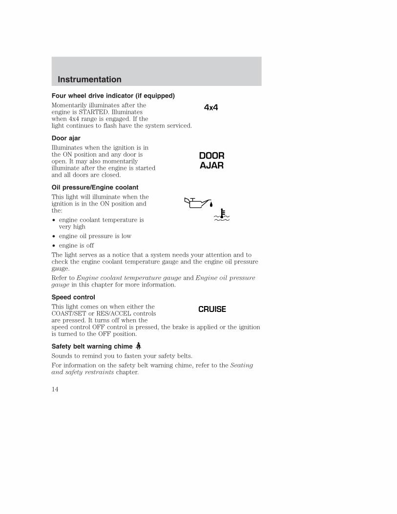
Four wheel drive indicator (if equipped)Momentarily illuminates after theengine is STARTED. Illuminateswhen 4x4 range is engaged. If thelight continues to flash have the system serviced.
Door ajarIlluminates when the ignition is inthe ON position and any door isopen. It may also momentarilyilluminate after the engine is startedand all doors are closed.
Oil pressure/Engine coolantThis light will illuminate when theignition is in the ON position andthe:
• engine coolant temperature isvery high
• engine oil pressure is low
• engine is off
The light serves as a notice that a system needs your attention and tocheck the engine coolant temperature gauge and the engine oil pressuregauge.
Refer to Engine coolant temperature gauge and Engine oil pressuregauge in this chapter for more information.
Speed controlThis light comes on when either theCOAST/SET or RES/ACCEL controlsare pressed. It turns off when thespeed control OFF control is pressed, the brake is applied or the ignitionis turned to the OFF position.
Safety belt warning chimeSounds to remind you to fasten your safety belts.
For information on the safety belt warning chime, refer to the Seatingand safety restraints chapter.
4x4
DOORAJAR
CRUISE
Instrumentation
14

Belt minder chimeSounds intermittently to remind you to fasten your safety belts.
For information on the safety belt minder chime, refer to the Seatingand safety restraints chapter.
Supplemental restraint system (SRS) warning chimeFor information on the SRS warning chime, refer to the Seating andsafety restraints chapter.
Key-in-ignition warning chimeSounds when the ignition key is left in the ignition in the OFF/LOCK orACC position and the driver’s door is opened.
Headlamps on warning chimeSounds when the headlamps or parking lamps are on, the ignition is off(and the key is not in the ignition) and the driver’s door is opened.
Parking brake ON warning chimeSounds when the parking brake is set, the engine is running and thevehicle is driven more than 5 Km (3 mph).
Instrumentation
15
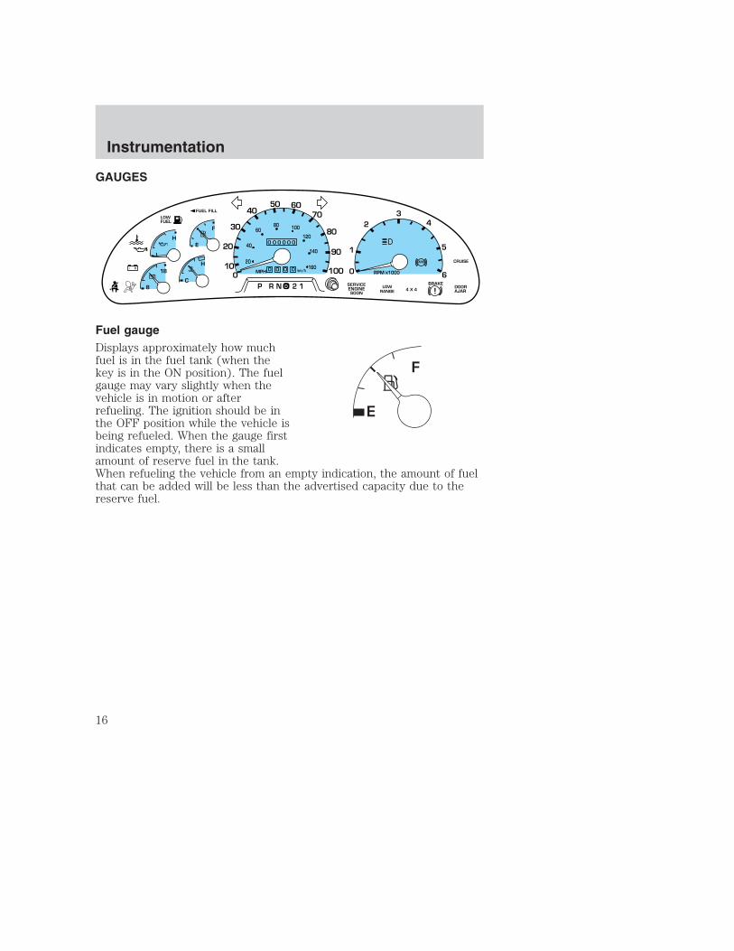
GAUGES
Fuel gaugeDisplays approximately how muchfuel is in the fuel tank (when thekey is in the ON position). The fuelgauge may vary slightly when thevehicle is in motion or afterrefueling. The ignition should be inthe OFF position while the vehicle isbeing refueled. When the gauge firstindicates empty, there is a smallamount of reserve fuel in the tank.When refueling the vehicle from an empty indication, the amount of fuelthat can be added will be less than the advertised capacity due to thereserve fuel.
0
0 0 0 0
0 0 0 0 0
MPH
20
km/h
40
6080 100
120
140
160
010
20
30
4050 60
70
80
90
100
LOWFUEL
CRUISEABS
+ -
L
E
F
H
RPM 1000X0
1
23
5
6
4
P R N 2 18C
18
H
D
FUEL FILL
DOORAJAR
LOWRANGE 4 X 4
BRAKE
!SERVICEENGINESOON
Instrumentation
16

SpeedometerIndicates the current vehicle speed.
Engine coolant temperature gaugeIndicates the temperature of theengine coolant. At normal operatingtemperature, the needle remainswithin the normal area (the areabetween the “H” and “C”). If itenters the red section, the engine isoverheating. Stop the vehicle assoon as safely possible, switch offthe engine immediately and let theengine cool. Refer to Enginecoolant in the Maintenance andcare chapter.
Never remove the coolant reservoir cap while the engine isrunning or hot.
This gauge indicates the temperature of the engine coolant, not thecoolant level. If the coolant is not at its proper level the gauge indicationwill not be accurate.
H
C
Instrumentation
17

OdometerRegisters the total kilometers(miles) of the vehicle.
Trip odometerRegisters the kilometers (miles) ofindividual journeys. To reset,depress the control.
TachometerIndicates the engine speed inrevolutions per minute.
Driving with your tachometerpointer at the top of the scale maydamage the engine.
Instrumentation
18

Battery voltage gaugeThis shows the battery voltage whenthe ignition is in the ON position. Ifthe pointer moves and stays outsidethe normal operating range (asindicated by arrows), have thevehicle’s electrical system checkedas soon as possible.
Engine oil pressure gaugeThis shows the engine oil pressurein the system. Sufficient pressureexists as long as the needle remainsin the normal range (the areabetween the “L” and “H”).
If the gauge indicates low pressure,stop the vehicle as soon as safelypossible and switch off the engineimmediately. Check the oil level.Add oil if needed (refer to Engineoil in the Maintenance and carechapter). If the oil level is correct, have your vehicle checked at yourdealership or by a qualified technician.
TRIP COMPUTER (IF EQUIPPED)The trip computer tells you about the condition of your vehicle througha constant monitor of vehicle systems. You may select display features onthe trip computer for a display of status.
The appearance of your vehicle’s trip computer may differ depending onyour vehicle’s option package, but the functions are the same.
8
18
L
H
Instrumentation
19

The trip computer only operates with the ignition in the ON position.Trip computer features follow:
Selectable features
English/metric displayPress this control to change the tripcomputer display between metricand English units.
Mode controlEach press of the MODE control willdisplay a different feature as follows:
Average fuel economy. Thedisplay will indicate the vehicle’saverage fuel economy in liters/100km (or miles/gallon) since theaverage fuel economy was last reset.
If you calculate your average fueleconomy by dividing liters of fuelused by 100 kilometers traveled(miles traveled by gallons used), your figure may be different thandisplayed for the following reasons:
• your vehicle was not perfectly level during fill-up
• differences in the automatic shut-off points on the fuel pumps atservice stations
• variations in top-off procedure from one fill-up to another
• rounding of the displayed values to the nearest liter (gallon)
To reset the average fuel economy:
1. Press the MODE control repeatedly until average fuel economy isdisplayed (this is the only resettable display).
Instrumentation
20
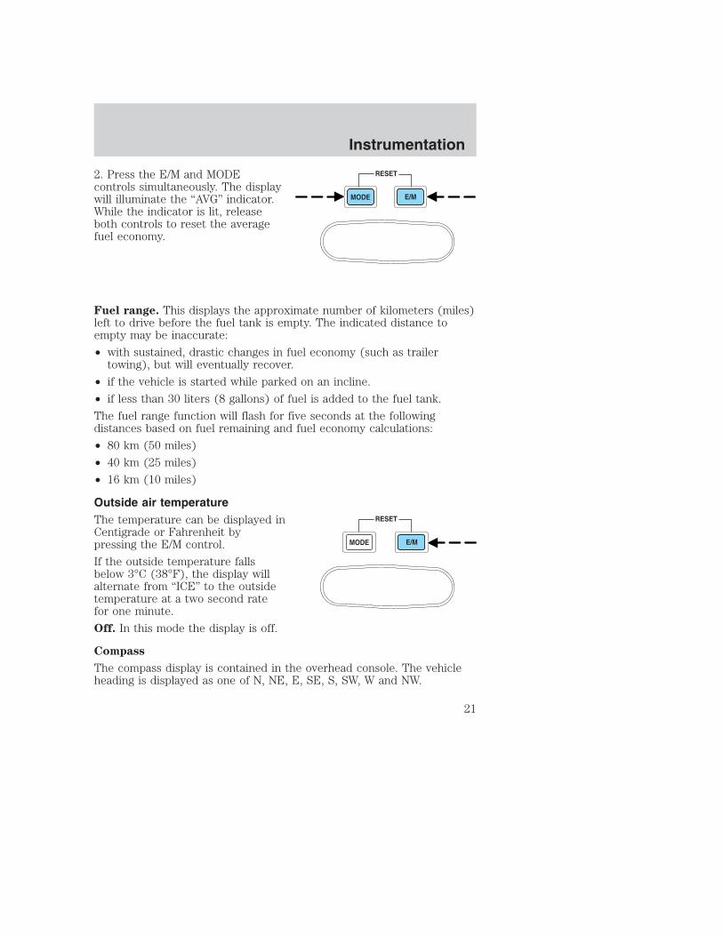
2. Press the E/M and MODEcontrols simultaneously. The displaywill illuminate the “AVG” indicator.While the indicator is lit, releaseboth controls to reset the averagefuel economy.
Fuel range. This displays the approximate number of kilometers (miles)left to drive before the fuel tank is empty. The indicated distance toempty may be inaccurate:
• with sustained, drastic changes in fuel economy (such as trailertowing), but will eventually recover.
• if the vehicle is started while parked on an incline.
• if less than 30 liters (8 gallons) of fuel is added to the fuel tank.
The fuel range function will flash for five seconds at the followingdistances based on fuel remaining and fuel economy calculations:
• 80 km (50 miles)
• 40 km (25 miles)
• 16 km (10 miles)
Outside air temperatureThe temperature can be displayed inCentigrade or Fahrenheit bypressing the E/M control.
If the outside temperature fallsbelow 3°C (38°F), the display willalternate from “ICE” to the outsidetemperature at a two second ratefor one minute.
Off. In this mode the display is off.
Compass
The compass display is contained in the overhead console. The vehicleheading is displayed as one of N, NE, E, SE, S, SW, W and NW.
Instrumentation
21

The compass heading is displayed in average fuel economy modes, fuelrange modes and temperature modes.
The compass reading may be affected when you drive near largebuildings, bridges, power lines and powerful broadcast antenna. Magneticor metallic objects placed in or on the vehicle may also affect compassaccuracy. Adjustments may need to be made to the zone and calibrationof the compass.
Compass zone adjustment1. Determine which magnetic zoneyou are in for your geographiclocation by referring to the zonemap.
2. Locate the trip computer on theoverhead console.
3. Turn ignition to the ON position.
1
2
3
4
56
7 8 9
10
11
12
13
1415
Instrumentation
22

4. Press and hold both tripcomputer controls. Afterapproximately four seconds, the tripcomputer will enter zone settingmode. Zone setting mode isindicated when the display lights the“ZONE” indicator.
5. Release both controls.Subsequent pressing of eithercontrol will increment the zone.Press the control repeatedly untilthe correct zone setting for your geographic location is displayed on thetrip computer.
6. To exit the zone setting mode and save the displayed zone in memory,release both controls for greater than five seconds.
Compass calibration adjustmentPerform this adjustment in an open area free from steel structures andhigh voltage lines.
For optimum calibration, turn off all electrical accessories (heater/airconditioning, wipers, etc.) and make sure all vehicle doors are shut.
1. Locate the trip computer located in the overhead console.
2. Start the vehicle.
3. Press and hold both tripcomputer controls. Afterapproximately eight seconds, thetrip computer will enter CAL mode.CAL mode is indicated when thedisplay lights the “CAL” indicator.
4. Release both controls. The displaywill return to normal, except thatthe CAL indicator will remain lituntil the compass is sucessfullycalibrated.
5. Slowly drive the vehicle in a circle (less than 5 km/h [3 mph]) untilthe CAL indicator turns off. It may take up to five circles to completecalibration.
6. The compass is now calibrated.
Instrumentation
23

HEADLAMP CONTROLRotate the headlamp control to thefirst position to turn on the parkinglamps. Rotate to the second positionto also turn on the headlamps.
Autolamp control (if equipped)The autolamp system provides lightsensitive automatic on-off control ofthe exterior lights normallycontrolled by the headlamp control.
The autolamp system also keeps thelights on for approximately 20seconds after the ignition switch isturned to OFF.
To program the autolamp feature, do the following:
1. Start with the ignition in OFF and the autolamps selected.
2. Deselect the autolamps.
3. Put the ignition in RUN.
4. Put the ignition in OFF.
5. Select the autolamps. Steps 2 through 5 must be performed within a10 second period. At this point, the headlamps and parking lamps willturn on.
6. Deselect the autolamps after the desired autolamp delay time(maximum of 3 minutes). At this point, the headlamps and parkinglamps will turn off.
A
Controls and features
24

High beams• Push forward to activate.
• Pull toward you to deactivate.
Flash to passPull toward you to activate andrelease to deactivate.
Daytime running lamps (DRL) (if equipped)Turns the headlamps on with a reduced output. To activate:
• the ignition must be in the ON position and
• the headlamp control is in the OFF or Parking lamps position.
Always remember to turn on your headlamps at dusk or duringinclement weather. The Daytime Running Lamp (DRL) system
does not activate with your tail lamps and generally may not provideadequate lighting during these conditions. Failure to activate yourheadlamps under these conditions may result in a collision.
Controls and features
25

Foglamp control (if equipped)The headlamp control also operatesthe foglamps. The foglamps can beturned on only when the headlampcontrol is in the and positionand the high beams are not turnedon.
Pull headlamp control towards youto turn foglamps on. The foglampindicator light will illuminate.
PANEL DIMMER CONTROLUse to adjust the brightness of theinstrument panel during headlampand parklamp operation.
• Rotate up to brighten.
• Rotate down to dim.
• Rotate to full up position (pastdetent) to turn on interior lamps.
• Rotate to full down position (pastdetent) to turn off interior lamps.
POWER ADJUSTABLE FOOT PEDALS (IF EQUIPPED)The accelerator and brake pedalshould only be adjusted when thevehicle is stopped and the gearshiftlever is in the P(Park) position.
Press and hold the rocker control toadjust accelerator and brake pedal.
• Press the left side of the control to adjust the pedals toward you.
• Press the right side of the control to adjust the pedals away from you.
The adjustment allows for approximately 76 mm (3 inches) of maximumtravel.
Never adjust the accelerator and brake pedal with feet on pedalsor while the vehicle is moving.
PANELDIM
PEDALS
Controls and features
26

4WD CONTROL (IF EQUIPPED)This control operates the 4WD.Refer to the Driving chapter formore information.
REVERSE SENSING SYSTEM (IF EQUIPPED)The reverse sensing system (RSS) sounds a tone to warn the driver ofobstacles near the rear bumper when the reverse gear is selected.
To help avoid personal injury, please read and understand thelimitations on the reverse sensing system described below.
Reverse sensing is only an assist for some (generally large and fixed)objects when moving in reverse on a flat surface at “parking speeds” ofapproximately 6 km/h (4 mph) or less. The weather may also affect thefunction of RSS. RSS may have reduced performance, or be activatedin inclement weather. It is the driver’s responsibility for ensuring thattheir path is clear when operating the vehicle.
To help avoid personal injury, always use caution when inreverse and when using the reverse sensing system.
This system is not designed to prevent contact with small ormoving objects. The system is designed to provide a warning to
assist the driver in detecting large stationary objects to avoid damagingthe vehicle. The system may not detect smaller objects, particularlythose close to the ground.
The RSS will assist the driver in detecting certain objects while thevehicle slowly moves in reverse at speeds less than 6 km/h (4 mph). TheRSS is not effective at speeds greater than 6 km/h (4 mph) and may notdetect certain angular or moving objects.
4X4HIGH2WD
4X4LOW
Controls and features
27

The reverse sensing system detectsobstacles within approximately 1.8meters (5.9 ft.) of the rear bumperwith a decreased coverage area atthe outer corners of the bumper,(refer to the figures for approximatezone coverage areas). As you movecloser to the obstacle, the rate ofthe tone increases. When thedistance to the obstacle is less than25.0 cm (10 in.), the tone will soundcontinuously. If the system detects astationary or receding object furtherthan 25.0 cm (10 in.) from the sideof the vehicle, the tone will soundfor only three seconds. Once thesystem detects an objectapproaching, the tone will soundagain.
The reverse sensing system isautomatically enabled when the gearselector is placed in R (Reverse)and the ignition is ON. A reversesensing control allows the driver todisable the reverse sensing system only when the ignition is ON, and thegear selector is in R (Reverse).
The OFF indicator remains illuminated when the system is disabled. Thesystem defaults to ON every time the reverse gear is selected. Press thecontrol to disable or enable the system.
The indicator will remain illuminated to indicate a failure of the reversesensing system.
The reverse sensing system may have reduced performance or anincreased chance of false detection if the tailgate is not locked in thevertical position. When the tailgate is down, the driver may experience acontinuous or intermittent tone. This also applies if items being hauled inthe box do not fit entirely inside and protrude rearward.
OFF
Controls and features
28

Always keep the sensors (located on the rear bumper/fascia) freefrom dirt, snow and ice (do not clean the sensors with sharpobjects). These elements may cause the system to operateinaccurately.
If the vehicle sustains damage to the rear bumper/fascia, leavingit misaligned or bent, the sensing zone may be altered causinginaccurate measurement of obstacles or false alarms.
AUXILIARY POWER POINTPower outlets are designed foraccessory plugs only. Do nothang any type of accessory oraccessory bracket from the plug.Improper use of the poweroutlet can cause damage notcovered by your warranty.
The auxiliary power point is locatedon the instrument panel.
Do not plug optional electrical accessories into the cigarette lighter. Usethe power point.
CLIMATE CONTROL SYSTEM
Heater only system (if equipped)
Fan speed controlControls the volume of air circulatedin the vehicle.
POWER POINT
OFF
Controls and features
29

Temperature controlControls the temperature of theairflow inside the vehicle. Onheater-only systems, the air cannotbe cooled below the outsidetemperature.
Mode selector controlControls the direction of the airflowto the inside of the vehicle.
• (Panel) -Distributes outside air through the instrument panelregisters.
• OFF-Outside air is shut out and the fan will not operate. For shortperiods of time only, use this mode to prevent undesirable odors fromentering the vehicle.
• (Panel and floor) -Distributes outside air through the instrumentpanel registers and the floor ducts.
• (Floor) -Allows for maximum heating. Distributes outside airthrough the floor ducts.
• (Floor and defrost) -Distributes outside air through the floorducts and the windshield defroster ducts.
• (Defrost) -Distributes outside air through the windshielddefroster ducts. It can be used to clear ice or fog from the windshield.
Operating tips• In humid weather conditions, place the climate control system in
DEF before driving. This will reduce fogging on your windshield. Oncethe windshield has been cleared, operate the climate control system asdesired.
• To reduce humidity buildup inside the vehicle in cold weatherconditions, don’t drive with the climate control system in the OFFposition.
• Under normal weather conditions, your vehicle’s climate controlsystem should be left in any position other than MAX A/C or OFFwhen the vehicle is parked. This allows the vehicle to “breathe”through the outside air inlet duct.
OFF
Controls and features
30

• Under snowy or dirty weather conditions, your vehicle’s climatecontrol system should be left in the OFF position when the vehicle isparked. This allows the climate control system to be free fromcontamination of outside pollutants.
• Do not put objects under the front seat that will interfere with theairflow to the rear seats (if equipped).
• Remove any snow, ice or leavesfrom the air intake area at thebase of the windshield.
• Do not place objects over the defroster outlets. These objects mayblock airflow and reduce visibility through the windshield. Avoidplacing small objects on top of the instrument panel. These objectsmay fall down into the defroster outlets and block airflow, in additionto damaging the climate control system.
Do not place objects on top of the instrument panel, as theseobjects may become projectiles in a collision or a sudden stop.
Manual heating and air conditioning system
Fan speed controlControls the volume of air circulatedin the vehicle.
OFF
A/C
MAXA/C
Controls and features
31

Temperature control knobControls the temperature of theairflow inside the vehicle.
Mode selector controlControls the direction of the airflowto the inside of the vehicle.
The air conditioning compressor can operate in all modes exceptand . However, the air conditioning will only function if the outsidetemperature is about 6°C (43°F) or higher.
Since the air conditioner removes considerable moisture from the airduring operation, it is normal if clear water drips on the ground underthe air conditioner drain while the system is working and even after youhave stopped the vehicle.
• MAX A/C-Uses recirculated air to cool the vehicle. MAX A/C is noisierthan A/C but more economical and will cool the inside of the vehiclefaster. Airflow will be from the instrument panel registers. This modecan also be used to prevent undesirable odors from entering thevehicle.
• A/C-Uses outside air to cool the vehicle. It is quieter than MAX A/Cbut not as economical. Airflow will be from the instrument panelregisters.
• (Panel) -Distributes outside air through the instrument panelregisters. However, the air will not be cooled below the outsidetemperature because the air conditioning does not operate in thismode.
• OFF-Outside air is shut out and the fan will not operate. For shortperiods of time only, use this mode to prevent undesirable odors fromentering the vehicle.
• (Panel and floor) -Distributes outside air through the instrumentpanel registers and the floor ducts. Heating and air conditioningcapabilities are provided in this mode. For added customer comfort,when the temperature control knob is anywhere in between the full
OFF
A/C
MAXA/C
Controls and features
32

hot and full cold positions, the air distributed through the floor ductswill be slightly warmer than the air sent to the instrument panelregisters.
• (Floor) -Allows for maximum heating by distributing outside airthrough the floor ducts. However, the air will not be cooled below theoutside temperature because the air conditioning does not operate inthis mode.
• (Floor and defrost) -Distributes outside air through thewindshield defroster ducts and the floor ducts. Heating and airconditioning capabilities are provided in this mode. For addedcustomer comfort, the air distributed through the floor ducts will beslightly warmer than the air sent to the windshield defroster ducts. Ifthe temperature is about 6°C (43°F) or higher, the air conditioner willautomatically dehumidify the air to reduce fogging.
• (Defrost) -Distributes outside air through the windshielddefroster ducts. It can be used to clear ice or fog from the windshield.If the temperature is about 6°C (43°F) or higher, the air conditionerwill automatically dehumidify the air to reduce fogging.
Operating tips• In humid weather conditions, place the climate control system in DEF
before driving. This will reduce fogging on your windshield. Once thewindshield has been cleared, operate the climate control system asdesired.
• To reduce humidity buildup inside the vehicle in cold weatherconditions, don’t drive with the climate control system in the OFF orMAX A/C position.
• To reduce humidity buildup inside the vehicle in warm weatherconditions, don’t drive with the climate control system in the OFFposition.
• Under normal weather conditions, your vehicle’s climate controlsystem should be left in any position other than MAX A/C or OFFwhen the vehicle is parked. This allows the vehicle to “breathe”through the outside air inlet duct.
• Under snowy or dirty weather conditions, your vehicle’s climatecontrol system should be left in the OFF position when the vehicle isparked. This allows the climate control system to be free fromcontamination of outside pollutants.
Controls and features
33

• If your vehicle has been parked with the windows closed during warmweather conditions, the air conditioner will perform more efficiently incooling the vehicle if driven for two or three minutes with thewindows open. This will force most of the hot, stale air out of thevehicle. Once the vehicle has been “aired out”, operate the climatecontrol system as desired.
• Do not put objects under the front seat that will interfere with theairflow to the rear seats (if equipped).
• Remove any snow, ice or leavesfrom the air intake area at thebase of the windshield.
• Do not place objects over the defroster outlets. These objects canblock airflow and reduce your ability to see through your windshield.Avoid placing small objects on top of the instrument panel. Theseobjects may fall down into the defroster outlets and block airflow, inaddition to damaging the climate control system.
Do not place objects on top of the instrument panel, as theseobjects may become projectiles in a collision or sudden stop.
To aid in side window defogging/demisting in cold weather conditions:
1. Select PANEL & FLOOR
2. Set the temperature control to full heat
3. Set the fan speed to HI
4. Direct the outer panel vents towards to side windows
To increase airflow to the outer panel vents, close the central panelvents.
Controls and features
34

USING YOUR AUDIO SYSTEM
AM/FM Stereo
Volume/power controlPress the control to turn the audiosystem on or off.
Turn the control to raise or lowervolume.
1 2 3 4 AM/FM
SEEKTONE
CLK TUNE
TONE VOL
12
FMST DX
VOLPUSH
ON
VOLPUSH
ON
VOLPUSH
ON
Controls and features
35

If the volume is set above a certain level and the ignition is turned off,the volume will come back on at a “nominal” listening level when theignition switch is turned back on.
AM/FM selectThe AM/FM select control works inradio mode.
AM/FM select in radio modeThis control allows you to select AM or FM frequency bands. Press thecontrol to switch between AM, FM1 or FM2 memory preset stations.
Tune adjustThe tune control works in radio mode.
Tune adjust in radio mode• Press to move to the next
frequency down the band(whether or not a listenablestation is located there). Hold thecontrol to move through thefrequencies quickly.
• Press to move to the next frequency up the band (whether or nota listenable station is located there). Hold for quick movement.
Seek functionThe seek function control works in radio mode.
Seek function in radio mode• Press to find the next
listenable station down thefrequency band.
• Press to find the nextlistenable station up thefrequency band.
AM/FM
SEEK
TUNE
SEEK
TUNE
Controls and features
36

Radio station memory presetThe radio is equipped with four station memory preset controls. Thesecontrols can be used to select up to four preset AM stations and eightFM stations (four in FM1 and four in FM2).
Setting memory preset stations1. Select the frequency band with the AM/FM select control.
2. Select a station. Refer to Tune adjust or Seek function for moreinformation on selecting a station.
3. Press and hold a memory preset control until the sound returns,indicating the station is held in memory on the control you selected.
Bass adjustThe bass adjust control allows youto increase or decrease the audiosystem’s bass output.
Press the TONE control once, thenuse the volume knob to adjust thedesired level.
Treble adjustThe treble adjust control allows youto increase or decrease the audiosystem’s treble output.
Press the TONE control twice, thenuse the volume knob to adjust thedesired level.
1 2 3 4
TONE
CLK
VOLPUSH
ON
TONE
CLK
VOLPUSH
ON
Controls and features
37

Speaker balance adjustSpeaker sound distribution can beadjusted between the right and leftspeakers.
Press the TONE control three times,then use the volume knob to adjustthe desired level.
Speaker fade adjust (if equipped)Speaker sound can be adjustedbetween the front and rearspeakers.
Press the TONE control four times,then use the volume knob to adjustthe desired level.
Setting the clockPress CLK to toggle betweenlistening frequencies and clockmode.
To set the hour, press and hold theCLK control until CLOCK SETappears in the display and press theSEEK control:
• to decrease hours and
• to increase hours.
TONE
CLK
VOLPUSH
ON
TONE
CLK
VOLPUSH
ON
TONE
CLK
SEEK SEEK
TUNE TUNE
Controls and features
38
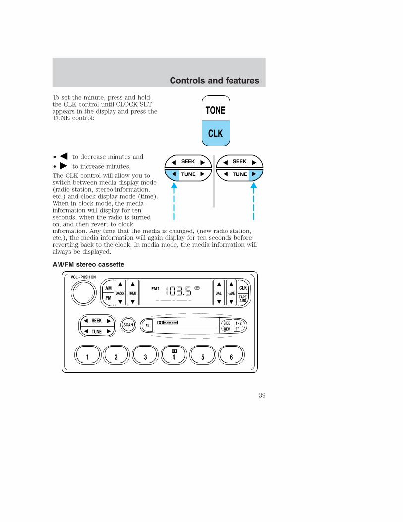
To set the minute, press and holdthe CLK control until CLOCK SETappears in the display and press theTUNE control:
• to decrease minutes and
• to increase minutes.
The CLK control will allow you toswitch between media display mode(radio station, stereo information,etc.) and clock display mode (time).When in clock mode, the mediainformation will display for tenseconds, when the radio is turnedon, and then revert to clockinformation. Any time that the media is changed, (new radio station,etc.), the media information will again display for ten seconds beforereverting back to the clock. In media mode, the media information willalways be displayed.
AM/FM stereo cassette
TONE
CLK
SEEK
TUNE
SEEK
TUNE
SCAN
BASS TREB BAL FADE
SIDEEJ
REW FF1 - 2
TAPEAMS
VOL - PUSH ON
SEEK
TUNE
AM
FM
CLK
1 2 3 4 5 6
FM1 ST
Controls and features
39

Volume/power controlPress the control to turn the audiosystem on or off.
Turn the control to raise or lowervolume.
If the volume is set above a certain level and the ignition is turned off,the volume will come back on at a “nominal” listening level when theignition switch is turned back on.
AM/FM selectThe AM/FM select control works inradio and tape modes.
AM/FM select in radio modeThis control allows you to select AM or FM frequency bands. Press theAM control to select from AM selections, and press the FM control toselect from FM1 or FM2 memory preset stations.
AM/FM select in tape modePress this control to stop tape play and begin radio play.
VOL - PUSH ON
VOL - PUSH ON
AM
FM
Controls and features
40

Tune adjustThe tune control works in radio mode.
Tune adjust in radio mode• Press to move to the next
frequency down the band(whether or not a listenablestation is located there). Hold thecontrol to move through thefrequencies quickly.
• Press to move to the next frequency up the band (whether or nota listenable station is located there). Hold for quick movement.
Seek functionThe seek function control works in radio mode.
Seek function in radio mode• Press to find the next
listenable station down thefrequency band.
• Press to find the nextlistenable station up thefrequency band.
Scan functionThe scan function works in radiomode.
Scan function in radio modePress the SCAN control to hear a brief sampling of all listenable stationson the frequency band. Press the SCAN control again to stop the scanmode.
Radio station memory presetThe radio is equipped with six station memory preset controls. Thesecontrols can be used to select up to six preset AM stations and twelveFM stations (six in FM1 and six in FM2).
SEEK
TUNE
SEEK
TUNE
SCAN
Controls and features
41

Setting memory preset stations1. Select the frequency band with the AM or the FM select control.
2. Select a station. Refer to Tune adjust or Seek function for moreinformation on selecting a station.
3. Press and hold a memory preset control until the sound returns,indicating the station is held in memory on the control you selected.
Bass adjustThe bass adjust control allows youto increase or decrease the audiosystem’s bass output.
Treble adjustThe treble adjust control allows youto increase or decrease the audiosystem’s treble output.
1 2 3 4 5 6
BASS
TREB
Controls and features
42

Speaker balance adjustSpeaker sound distribution can beadjusted between the right and leftspeakers.
Speaker fade adjustSpeaker sound can be adjustedbetween the front and rearspeakers.
Tape select• To enter tape mode while in radio
mode, press the TAPE AMScontrol.
BAL
FADE
TAPEAMS
CLK
Controls and features
43

Automatic Music SearchThe Automatic Music Search featureallows you to quickly locate thebeginning of the tape selectionbeing played or to skip to the nextselection.
To activate the feature, momentarilydepress the TAPE AMS button.Then, press either REW (for thebeginning of the current selection) or FF (to advance to the nextselection). The tape deck stops and returns to play mode when the AMScircuit senses a blank section on the tape.
In order to ensure proper operation of the AMS feature, the tape MUSThave a blank section of at least four seconds duration between programs.
Tape direction selectPress SIDE and 1–2 at the sametime to play the alternate side of atape.
Eject functionPress the control to stop and eject atape.
Dolby� noise reductionDolby� noise reduction operatesonly in tape mode. Dolby� noisereduction reduces the amount ofhiss and static during tape playback.
Press the control to activate (and deactivate) Dolby� noisereduction.
Dolby� noise reduction is manufactured under license from Dolby�Laboratories Licensing Corporation. “Dolby�” and the double-D symbolare registered trademarks of Dolby Laboratories Licensing Corporation.
TAPEAMS
CLK
SIDEREW FF
1 - 2
EJ
4
Controls and features
44

Setting the clockPress CLK to toggle betweenlistening frequencies and clockmode while in radio mode.
To set the hour, press and hold theCLK control and press the SEEKcontrol:
• to decrease hours and
• to increase hours.
To set the minute, press and holdthe CLK control and press theTUNE control:
• to decrease minutes and
• to increase minutes.
TAPEAMS
CLK
SEEK SEEK
TUNE TUNE
TAPEAMS
CLK
SEEK
TUNE
SEEK
TUNE
Controls and features
45

The CLK control will allow you to switch between media display mode(radio station, stereo information, etc.) and clock display mode (time).When in clock mode, the media information will display for 10 seconds,when the radio is turned on, and then revert to clock information. Anytime that the media is changed, (new radio station, etc.), the mediainformation will again display for 10 seconds before reverting back to theclock. In media mode, the media information will always be displayed.
Premium AM/FM Stereo/Cassette/Single CD
Volume/power controlPress the control to turn the audiosystem on or off.
Audio power can also be turned onby pressing the AM/FM selectcontrol or the tape/CD selectcontrol. Audio power is turned offby using the volume/power control.
FM 1AMC
BL RF
REW FF
SCAN BASS TREB SEL BAL
TAPE
DISC
EJ CD
FADE
AUTO
CLK
SIDE 1-2 COMP SHUFFLE
EJ
MUTE
VOL PUSH ON
SEEK
TUNE
AM FM
1 2 3 4 5 6
DOLBY B NR
ST
VOL - PUSH ON
Controls and features
46

Turn control to raise or lowervolume.
If the volume is set above a certain level and the ignition is turned off,the volume will come back on at a “nominal” listening level when theignition switch is turned back on.
AM/FM selectThe AM/FM select control works inradio, tape and CD modes.
AM/FM select in radio modeThis control allows you to select AM or FM frequency bands. Press thecontrol to switch between AM, FM1 or FM2 memory preset stations.
AM/FM select in tape modePress this control to stop tape play and begin radio play.
AM/FM select in CD or CD changer mode (if equipped)Press this control to stop CD play and begin radio play.
Tune adjustThe tune control works in radio or CD changer mode.
Tune adjust in radio mode• Press to move to the next
frequency down the band(whether or not a listenablestation is located there). Hold thecontrol to move through thefrequencies quickly.
• Press to move to the nextfrequency up the band (whether or not a listenable station is locatedthere). Hold for quick movement.
VOL - PUSH ON
AM FM
Controls and features
47

Tune adjust for CD changer (if equipped)• Press to select the previous
disc in the CD changer. (Play willbegin on the first track of thedisc unless the CD changer is inshuffle mode. Refer to Shufflefeature for more information.Hold the control to continuereversing through the remaining discs.
• Press to select the next disc in the CD changer. Hold the controlto fast-forward through the remaining discs.
Seek functionThe seek function control works in radio, tape or CD mode.
Seek function in radio mode• Press to find the next
listenable station down thefrequency band.
• Press to find the nextlistenable station up thefrequency band.
Seek function in tape mode• Press to listen to the previous selection on the tape.
• Press to listen to the next selection on the tape.
Seek function for CD or CD changer (if equipped)• Press to seek to the previous
track of the current disc. If aselection has been playing forthree seconds or more and youpress , the CD changer willreplay that selection from thebeginning.
• Press to seek forward to the next track of the current disc. Afterthe last track has been completed, the first track of the current discwill automatically replay.
Controls and features
48

Scan functionThe scan function works in radio,tape or CD mode.
Scan function in radio modePress the SCAN control to hear a brief sampling of all listenable stationson the frequency band. Press the control again to stop the scan mode.
Scan function in tape modePress the SCAN control to hear a short sampling of all selections on thetape. (The tape scans in a forward direction. At the end of the tape’sfirst side, direction automatically reverses to the opposite side of thetape.) To stop on a particular selection, press the control again.
Scan function in CD or CD changer mode (if equipped)Press the SCAN control to hear a short sampling of all selections on theCD. (The CD scans in a forward direction, wrapping back to the firsttrack at the end of the CD.) To stop on a particular selection, press thecontrol again.
Radio station memory presetThe radio is equipped with six station memory preset controls. Thesecontrols can be used to select up to six preset AM stations and twelveFM stations (six in FM1 and six in FM2).
Setting memory preset stations1. Select the frequency band withthe AM/FM select control.
2. Select a station. Refer to Tuneadjust or Seek function for more information on selecting a station.
3. Press and hold a memory preset control until the sound returns,indicating the station is held in memory on the control you selected.
SCAN
AM FM
REW FF SIDE 1-2 COMP SHUFFLE
1 2 3 4 5 6
Controls and features
49

Autoset memory presetAutoset allows you to set strong radio stations without losing youroriginal manually set preset stations. This feature is helpful on tripswhen you travel between cities with different radio stations.
Starting autoset memory preset1. Select a frequency using the AM/FM select controls.
2. Press the AUTO control.
3. When the first six strong stationsare filled, the station stored inmemory preset control 1 will startplaying.
If there are less than six strongstations available on the frequencyband, the remaining memory presetcontrols will all store the last strong station available.
These stations are temporarily stored in the memory preset controls(until deactivated) and are accessed in the same manner as your originalpresets.
To deactivate autoset and return to your audio system’s manually setmemory stations, press the AUTO control again.
Bass adjustThe bass adjust control allows youto increase or decrease the audiosystem’s bass output.
Press the BASS control then press:
• to decrease the bass outputand
• to increase the bass output.
AUTO
CLK
BASS TREB
SEL
Controls and features
50

Treble adjustThe treble adjust control allows youto increase or decrease the audiosystem’s treble output.
Press the TREB control then press:
• to decrease the treble outputand
• to increase the treble output.
Speaker balance adjustSpeaker sound distribution can beadjusted between the right and leftspeakers.
Press the BAL control then press:
• to shift sound to the left and
• to shift sound to the right.
BASS TREB
SEL
BAL FADE
SEL
Controls and features
51

Speaker fade adjustSpeaker sound can be adjustedbetween the front and rearspeakers.
Press the FADE control then press:
• to shift the sound to thefront and
• to shift the sound to the rear.
Tape/CD select• To begin tape play (with a tape
loaded into the audio system)while in the radio or CD mode,press the TAPE control. Press thebutton during rewind or fast forward to stop the rewind or fastforward function.
• To begin CD play (if CD(s) areloaded), press the CD control.The first track of the disc willbegin playing. If returning fromradio or tape mode, CD play will begin where it stopped last.
With the dual media audio system, press the CD control to togglebetween single CD and CD changer play (if equipped).
Do not insert any promotional (odd shaped or sized) discs, ordiscs with removable labels into the CD player as jamming mayoccur.
BAL FADE
SEL
TAPE CD
TAPE CD
Controls and features
52
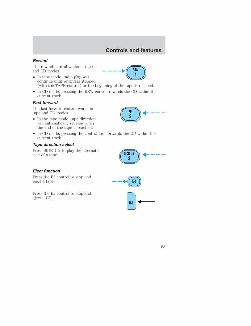
RewindThe rewind control works in tapeand CD modes.
• In tape mode, radio play willcontinue until rewind is stopped(with the TAPE control) or the beginning of the tape is reached.
• In CD mode, pressing the REW control rewinds the CD within thecurrent track.
Fast forwardThe fast forward control works intape and CD modes.
• In the tape mode, tape directionwill automatically reverse whenthe end of the tape is reached.
• In CD mode, pressing the control fast forwards the CD within thecurrent track.
Tape direction selectPress SIDE 1–2 to play the alternateside of a tape.
Eject functionPress the EJ control to stop andeject a tape.
Press the EJ control to stop andeject a CD.
REW
1
FF
2
SIDE 1-2
3
EJ
EJ
Controls and features
53

Dolby� noise reductionDolby� noise reduction operates intape mode. Dolby� noise reductionreduces the amount of hiss andstatic during tape playback.
Press the control to activate (and deactivate) the Dolby� noisereduction.
Dolby� noise reduction is manufactured under license from Dolby�Laboratories Licensing Corporation. “Dolby�” and the double-Dsymbol are registered trademarks of Dolby� Laboratories LicensingCorporation.
Compression adjustCompression adjust brings soft andloud CD passages together for amore consistent listening level.
Press the COMP control to activateand deactivate compression adjust.
Shuffle featureThe shuffle feature operates in CDmode (if equipped) and plays alltracks on the current disc in randomorder. If equipped with the CDchanger, the shuffle featurecontinues to the next disc after all tracks on the current disc are played.
Press the SHUFFLE control to start this feature. Random order play willcontinue until the SHUFFLE control is pressed again.
4
COMP
5
SHUFFLE
6
Controls and features
54

Setting the clockTo set the hour, press and hold theCLK control and press SEEK:
• to decrease hours and
• to increase hours.
To set the minute, press and holdthe CLK control and press TUNE:
• to decrease minutes and
• to increase minutes.
If your vehicle has a separate clockmodule, (other than the digital radiodisplay), the CLK button will notfunction in the above manner.
AUTO
CLK
SEEK SEEK
TUNE TUNE
AUTO
CLK
SEEK
TUNE
SEEK
TUNE
Controls and features
55

The CLK button will allow you toswitch between media display mode(radio station, stereo information,etc.) and clock display mode (time).When in clock mode, the mediainformation will display for 10seconds, when the radio is turnedon, and then revert to clockinformation. Any time that themedia is changed, (new radio station, etc.), the media information willagain display for 10 seconds before reverting back to the clock. In mediamode, the media information will always be displayed.
Mute modePress the MUTE control to mute theplaying media. Press the MUTEcontrol again to return to theplaying media.
Premium AM/FM Stereo In Dash Six CD Radio
AUTO
CLK
EJ
MUTE
LOAD EJ
SHUF COMPMUTE
SEL
BALBASS
FADETREB
SCAN DISCTUNE
PUSH ON
CD 1 2 3 4 5 6 MENUAMFM
SEEK REW FF
Controls and features
56

Volume/power controlPress the control to turn the audiosystem on or off.
Turn the control to raise or lowervolume.
If the volume is set above a certain level and the ignition is turned off,the volume will come back on at a “nominal” listening level when theignition switch is turned back on.
AM/FM selectThe AM/FM select control works inradio and CD modes.
AM/FM select in radio modeThis control allows you to select AM or FM frequency bands. Press thecontrol to switch between AM, FM1 or FM2 memory preset stations.
AM/FM select in CD modePress this control to stop CD play and begin radio play.
Tune adjustThe tune control works in radio or CD mode.
PUSH ON
CDAMFM
Controls and features
57

Tune adjust in radio mode• Press to move to the next
frequency down the band(whether or not a listenablestation is located there). Hold thecontrol to move through thefrequencies quickly.
• Press to move to the next frequency up the band (whether or nota listenable station is located there). Hold for quick movement.
Tune adjust for CD mode• Press to select the previous
disc. (Play will begin on the firsttrack of the disc unless shufflemode is engaged.) Refer toShuffle feature for moreinformation. Hold the control tocontinue reversing through the discs.
• Press to select the next disc. Hold the control to fast-forwardthrough the remaining discs.
Seek functionThe seek function works in radio or CD mode.
Seek function in radio mode• Press to find the next
listenable station down thefrequency band. SEEK DOWNwill display.
• Press to find the next listenable station up the frequency band.SEEK UP will display.
Controls and features
58
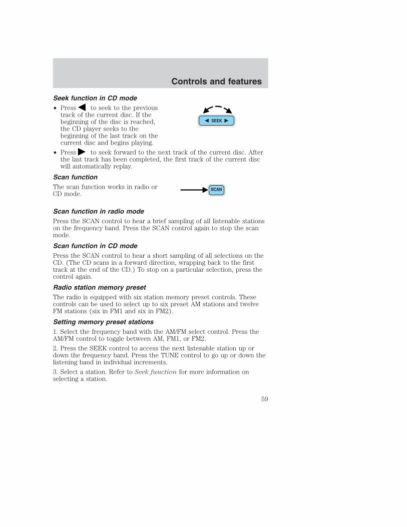
Seek function in CD mode• Press to seek to the previous
track of the current disc. If thebeginning of the disc is reached,the CD player seeks to thebeginning of the last track on thecurrent disc and begins playing.
• Press to seek forward to the next track of the current disc. Afterthe last track has been completed, the first track of the current discwill automatically replay.
Scan functionThe scan function works in radio orCD mode.
Scan function in radio modePress the SCAN control to hear a brief sampling of all listenable stationson the frequency band. Press the SCAN control again to stop the scanmode.
Scan function in CD modePress the SCAN control to hear a short sampling of all selections on theCD. (The CD scans in a forward direction, wrapping back to the firsttrack at the end of the CD.) To stop on a particular selection, press thecontrol again.
Radio station memory presetThe radio is equipped with six station memory preset controls. Thesecontrols can be used to select up to six preset AM stations and twelveFM stations (six in FM1 and six in FM2).
Setting memory preset stations1. Select the frequency band with the AM/FM select control. Press theAM/FM control to toggle between AM, FM1, or FM2.
2. Press the SEEK control to access the next listenable station up ordown the frequency band. Press the TUNE control to go up or down thelistening band in individual increments.
3. Select a station. Refer to Seek function for more information onselecting a station.
Controls and features
59

4. Press and hold a memory preset control. The playing media will mutemomentarily. When the sound returns, the station is held in memory onthe control you selected. The display will read SAVED.
AutostoreAutostore allows you to set the strongest local radio stations withoutlosing your original manually set preset stations. This feature is helpfulon trips when you travel between cities with different radio stations.
Starting autostore1. Press and momentarily hold the AM/FM control.
2. AUTOSET will flash in the displayas the frequency band is scrolledthrough.
3. When the six strongest stationsare filled, the station stored inmemory preset control 1 will start playing.
If there are less than six strong stations available on the frequency band,the remaining memory preset controls will all store the last strongstation available.
To deactivate autoset and return to your audio system’s manually setmemory stations, press the AM/FM control again.
CDAMFM
Controls and features
60

CD selectCD mode may be entered bypressing the CD control and theLOAD control. Load the CD into theaudio system. The first track of thedisc will begin playing. After that,CD play will begin where it stopped last.
If an alternative CD is desired, press the corresponding preset control(1–6) of a loaded CD, or press the TUNE control to access the otherloaded CDs.
NO CD will display if the CD control is activated when there is not a CDpresent in the audio system.
NO CD will illuminate in the display if the CD control and a presentnumber (that is currently empty) are pressed. The system will play thenext available disc.
If your vehicle is equipped with a CD changer, pressing the CD controlagain will allow you to toggle between accessing the multi disc systemand the CD changer. The display will read CD or CDDJ.
Do not insert any promotional (odd shaped or sized) discs, ordiscs with removable labels into the CD player as jamming mayoccur.
Display descriptionSix circles are always lit in the digital display. These signify the six CDslots in the audio system. When a disc is loaded into a particular slot(1–6), the number inside that specific circle lights. If the circle is empty,there is no CD in that particular slot.
LoadThe load feature allows you to loadsingle CDs into the player internalto the radio.
This six disc CD player is equipped with a CD door. Compactdiscs should only be inserted into the player after the door hasbeen opened by the player. Do not attempt to force the dooropen. Compact discs should only be loaded by pressing the LOADcontrol.
Controls and features
61

Press the LOAD control. (You can choose which slot will be loaded bypressing the desired preset number. If you do not choose a slot, thesystem will choose the next available one.) Wait until the CD door opens.Load the CD into the player. LOADING CD# is displayed. When the CDhas been loaded, the door will close and the CD will begin to play. Forexample, to load a CD into slot 2, press the LOAD control and then presspreset 2.
Auto loadThis feature allows you to autoloadup to 6 discs into the multi disc CDplayer internal to the radio.
Press and hold the LOAD control until AUTOLOAD # is displayed. TheCD door will open. Load the desired disc, one at a time. The CD isloaded into position and the audio system will display CD#. Each timethe CD door opens, INSERT CD# is displayed. The door will close andthe player will move to the next slot after each disc has been loaded.The process is repeated until all 6 slots are full. The audio system playsthe last CD loaded and the display is updated. If some slots are alreadyfull and autoload is activated, the system will fill all empty slots.
EjectPress the EJ control to stop andeject a CD. You can choose whichCD will be ejected by pressing theEJ control and the desired presetnumber (1–6). For example, to eject CD 2, press the EJ control and thenpress the preset 2 control. If you do not choose a specific CD, the playerwill eject the current CD.
If a CD is ejected and not removed from the door of the CD player, theplayer will automatically reload the CD. This feature may be used whenthe ignition is ON or OFF.
Auto ejectPress and momentarily hold the EJcontrol to engage auto eject. All CDswhich are present in the player willbe ejected one at a time. If a CD isejected and not removed from the door of the CD player, the player willautomatically reload the CD. This feature may be used when the ignitionis ON or OFF.
Controls and features
62

RewindThe rewind control works in CDmodes.
Press and hold the REW controluntil the desired selection isreached. If the beginning of the disc is reached, the CD will begin play atthe first track. Release the control to disengage rewind mode.
When in rewind mode, your audio system will automatically lower thevolume level of the playing media.
Fast forwardThe fast forward control works inCD modes.
Press and hold the FF control untilthe desired selection is reached. Ifthe end of the disc is reached, the CD will return to the first track onthe first disc. Release the control to disengage fast forward mode.
When in fast forward mode, your audio system will automatically lowerthe volume level of the playing media.
Shuffle featurePress the SHUF control until thedesired shuffle mode is displayed.The audio system will then engagethe desired shuffle mode.
When engaged, the shuffle feature has two different modes: SHUFFLEDISC and SHUFFLE TRK.
SHUFFLE DISC randomly plays tracks from all the discs presently in theaudio system.
SHUFFLE TRK plays all the tracks on the current disc in random order.
Compression feature (if equipped)The compression feature operates inCD mode and brings soft and loudCD passages together for a moreconsistent listening level.
SEL+MENU
Controls and features
63

On Audiophile audios, press the MENU control until compression statusis displayed. Press the SEL control to enable the compression featurewhen COMP OFF is displayed. Press the SEL control again to disable thefeature when COMP ON is displayed.
On Premium audios, press theCOMP control until COMP ON isdisplayed.
Bass adjustThe bass adjust control allows youto increase or decrease the audiosystem’s bass output.
Press the BASS control. Use theSEL control to increase or decreasethe amount of bass.
Treble adjustThe treble adjust control allows youto increase or decrease the audiosystem’s treble output.
Press the TREB control. Use theSEL control to increase or decreasethe amount of treble.
Speaker balance adjustSpeaker sound distribution can beadjusted between the right and leftspeakers.
Press the BAL control. Use the SELcontrol to adjust the sound betweenthe speakers.
Speaker fade adjustSpeaker sound can be adjustedbetween the front and rearspeakers.
Press the FADE control. Use theSEL control to adjust the soundbetween the front and rear speakers.
SEL
BASS
TREB
+
SEL
BASS
TREB
+
BAL
FADE
SEL+
BAL
FADE
SEL+
Controls and features
64

Menu modeThe MENU control allows you toaccess many different featureswithin your audio system. There arethree sets of menus availabledepending upon which mode orfeature is activated.
While in FM mode, two menus areavailable. If RDS is turned OFF,you can access the following:
• SELECT HOURS — Refer to Setting the clock.
• SELECT MINUTES — Refer to Setting the clock.
• RDS OFF — Refer to Radio data system feature.
If RDS is turned ON, you can access the following:
• TRAFFIC ON/OFF-Refer to Traffic announcements.
• FIND type-Refer to Program type.
• SHOW (NAME, TYPE, NONE)- Refer to Radio data system feature.
• RDS ON— Refer to Radio data system feature.
• SELECT HOURS — Refer to Setting the clock.
• SELECT MINUTES —Refer to Setting the clock.
When in CD mode, you can access: SELECT HOURS, SELECT MINUTESor COMP ON/OFF.
SELECT HOURS, SELECT MINUTES— Allows you to adjust the hoursand minutes. Refer to Setting the clock.
TRAFFIC ON/OFF— Traffic announcements can be programmed as localor distant. Refer to Traffic announcements.
RDS ON/OFF— This feature allows your audio system to receive textinformation from RDS-equipped FM radio stations. Refer to Radio DataSystem feature.
FIND type — Allows you to select your desired FM program type andsearch for that selection.
SHOW — Allows you to select from NAME (displays the name of theradio station), TYPE (displays the RDS program type: rock, jazz, etc.), orNONE (deactivates the RDS display).
Controls and features
65

Radio data system (RDS) featureThis feature allows your audiosystem to receive text informationfrom RDS-equipped FM radiostations.
To activate RDS:
• When in FM mode, press the MENU control until RDS OFF displays.
• Press the SEL control to engage this feature (RDS ON).
RDS features:
Once the RDS feature is on, press the MENU control to scroll throughthe following selections:
Traffic announcementsThis feature allows you to hear traffic announcements while in CD mode.These announcements are broadcast by traffic capable RDS stations.
When in this mode, traffic announcements will interrupt radio and CDplay.
• Press the MENU control until TRAFFIC is displayed.
• Press the SEL control to engage the feature. The display will readTRAFFIC ON.
This feature also allows you to control the volume of trafficannouncements. With the display reading TRAFFIC ON, adjust thevolume using the volume control to the desired level. The volume levelwill show at the bottom of the display. Interrupting trafficannouncements will be at the selected volume level.
To disengage the feature, press the MENU control until TRAFFIC ONdisplays. Press the SEL control. The display will read TRAFFIC OFF.
Traffic announcements not available in most U.S. markets.
SEL+MENU
Controls and features
66
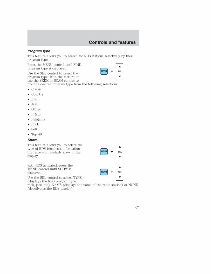
Program typeThis feature allows you to search for RDS stations selectively by theirprogram type.
Press the MENU control until FINDprogram type is displayed.
Use the SEL control to select theprogram type. With the feature on,use the SEEK or SCAN control tofind the desired program type from the following selections:
• Classic
• Country
• Info
• Jazz
• Oldies
• R & B
• Religious
• Rock
• Soft
• Top 40
ShowThis feature allows you to select thetype of RDS broadcast informationthe radio will regularly show in thedisplay.
With RDS activated, press theMENU control until SHOW isdisplayed.
Use the SEL control to select TYPE(displays the RDS program type:rock, jazz, etc), NAME (displays the name of the radio station) or NONE(deactivates the RDS display).
SEL+MENU
SEL+MENU
SEL+MENU
Controls and features
67

Digital signal processing (if equipped)The digital signal processing (DSP) feature allows you to change thesignal mode to suit your listening tastes.
Press the DSP control to access theDSP menu. Press the SEL control toenter one of the following modes:
• DSP OFF
• SIGNAL MODE
• OCCUPANCY MODE
Use the SEL control to select thedesired signal mode (the selectedmode will appear in the display).The following signal modes can beselected:
• DSP OFF—disengages the feature
• NEWS—”voice-only” type of sound with a limited audio band
• JAZZ CLUB—jazz club with clearly reflected sounds
• HALL—rectangular concert hall capacity of about 2 000
• CHURCH—church with a high vault
• STADIUM—outdoor stadium with a capacity of about 30 000
Press the DSP control again to access the occupancy modes. Use theSEL control to optimize the sound based upon the occupants in thevehicle. The following occupancy modes can be selected:
• ALL SEATS
• DRIVER SEAT
• REAR SEATS
DSP SEL+
SEL
Controls and features
68

Phone modeThis feature allows you to controlthe factory-installed cellular phone(if equipped) through the radiocontrols.
• Press the phone/mute control to enter phone mode. The playing mediawill mute.
• Use SEEK, TUNE or radio presets 1 through 6 to select a phonenumber previously programmed in the phone.
• Press the phone/mute control again to send and end calls.
This control will mute the playing media even if your vehicle is notequipped with a factory-installed cellular phone.
Press the control again to return to the playing media.
Setting the clockPress the MENU control untilSELECT HOUR or SELECTMINUTE is displayed.
Use the SEL control to manually setthe time.
• Press to increasehours/minutes.
• Press to decreasehours/minutes.
Cleaning compact discsInspect all discs for contamination before playing. If necessary, cleandiscs only with an approved CD cleaner and wipe from the center out tothe edge. Do not use circular motion.
CD and CD changer care• Handle discs by their edges only. Never touch the playing surface.
• Do not expose discs to direct sunlight or heat sources for extendedperiods of time.
• Do not insert more than one disc into each slot of the CD changermagazine.
SEL
Controls and features
69

Do not insert any promotional (odd shaped or sized) discs, ordiscs with removable labels into the CD player as jamming mayoccur.
Cleaning cassette player (if equipped)Clean the tape player head with a cassette cleaning cartridge after 10 to12 hours of play in order to maintain the best sound and operation.
Cassette and cassette player care• Use only cassettes that are 90 minutes long or less.
• Do not expose tapes to direct sunlight, high humidity, extreme heat orextreme cold. Allow tapes that may have been exposed to extremetemperatures to reach a moderate temperature before playing.
• Tighten very loose tapes by inserting a finger or pencil into the holeand turning the hub.
• Remove loose labels before inserting tapes.
• Do not leave tapes in the cassette player for a long time when notbeing played.
Radio frequency informationThe Federal Communications Commission (FCC) and the Canadian Radioand Telecommunications Commission (CRTC) establish the frequenciesAM and FM stations may use for their broadcasts. Allowable frequenciesare:
• AM 530, 540–1600, 1610 kHza
• FM 87.9b, 88.1–107.7, 107.9 MHz
Not all frequencies are used in a given area.aSome radios may tune up to 1710 kHz.bSome radios may tune down to 87.7 MHz.
Radio reception factorsThree factors can affect radio reception:
• Distance/strength.The further an FM signal travels, the weaker it is.The listenable range of the average FM station is approximately 40 km(24 miles). This range can be affected by “signal modulation.” Signalmodulation is a process radio stations use to increase theirstrength/volume relative to other stations.
Controls and features
70

• Terrain.Hills, mountains and tall buildings between your vehicle’santenna and the radio station signal can cause FM reception problems.Static can be caused on AM stations by power lines, electric fences,traffic lights and thunderstorms. Moving away from an interferingstructure (out of its “shadow”) returns your reception to normal.
• Station overload.Weak signals are sometimes captured by strongersignals when you pass a broadcast tower. A stronger signal maytemporarily overtake a weaker signal and play while the weak stationfrequency is displayed.
The audio system automatically switches to single channel reception if itwill improve the reception of a station normally received in stereo.
Audio system warranties and serviceRefer to the Warranty Guide for audio system warranty information.
If service is necessary, see your dealer or a qualified technician.
POSITIONS OF THE IGNITION1. ACCESSORY, allows the electricalaccessories such as the radio tooperate while the engine is notrunning.
2. LOCK, locks the steering wheel,automatic transmission gearshiftlever and allows key removal.
3. OFF, shuts off the engine and allaccessories without locking thesteering wheel.
4. ON, all electrical circuits operational. Warning lights illuminated. Keyposition when driving.
5. START, cranks the engine. Release the key as soon as the enginestarts.
3
1
2
5
4
Controls and features
71

TURN SIGNAL CONTROL• Push down to activate the left
turn signal.
• Push up to activate the right turnsignal.
SPEED CONTROL (IF EQUIPPED)
To turn speed control on• Press ON.
Vehicle speed cannot be controlleduntil the vehicle is traveling at orabove 48 km/h (30 mph).
Do not shift the gearshift leverinto N (Neutral) with the speedcontrol on.
Do not use the speedcontrol in heavy traffic or
on roads that are winding,slippery, or unpaved.
ON
OFF
Controls and features
72

To turn speed control off• Press OFF or
• Turn off the vehicle ignition.
Once speed control is switched off,the previously programmed setspeed will be erased.
To set a speed• Press SET ACCEL. For speed
control to operate, the speedcontrol must be ON and thevehicle speed must be greaterthan 48 km/h (30 mph).
If you drive up or down a steep hill, your vehicle speed may varymomentarily slower or faster than the set speed. This is normal.
Speed control cannot reduce the vehicle speed if it increases above theset speed on a downhill. If your vehicle speed is faster than the setspeed while driving on a downhill, you may want to shift to the nextlower gear or apply the brakes to reduce your vehicle speed.
If your vehicle slows down more than 16 km/h (10 mph) below your setspeed on an uphill, your speed control will disengage. This is normal.Pressing RES will re-engage it.
Do not use the speed control in heavy traffic or on roads thatare winding, slippery, or unpaved.
ON
OFF
RES
SETACCEL
COAST
Controls and features
73
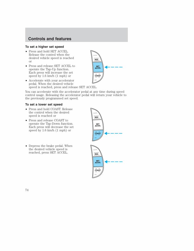
To set a higher set speed• Press and hold SET ACCEL.
Release the control when thedesired vehicle speed is reachedor
• Press and release SET ACCEL tooperate the Tap-Up function.Each press will increase the setspeed by 1.6 km/h (1 mph) or
• Accelerate with your acceleratorpedal. When the desired vehiclespeed is reached, press and release SET ACCEL.
You can accelerate with the accelerator pedal at any time during speedcontrol usage. Releasing the accelerator pedal will return your vehicle tothe previously programmed set speed.
To set a lower set speed• Press and hold COAST. Release
the control when the desiredspeed is reached or
• Press and release COAST tooperate the Tap-Down function.Each press will decrease the setspeed by 1.6 km/h (1 mph) or
• Depress the brake pedal. Whenthe desired vehicle speed isreached, press SET ACCEL.
RES
SETACCEL
COAST
RES
SETACCEL
COAST
RES
SETACCEL
COAST
Controls and features
74

To disengage speed control• Depress the brake pedal or
• Depress the clutch pedal(if equipped).
Disengaging the speed control willnot erase the previouslyprogrammed set speed.
Pressing OFF will erase thepreviously programmed set speed.
ON
OFF
Controls and features
75

To return to a previously set speed• Press RES. For RES to operate,
the vehicle speed must be fasterthan 48 km/h (30 mph).
Indicator lightThis light comes on when either theSET ACCEL or RES controls arepressed. The vehicle speed must beat or above 48 km/h (30 mph). It turns off when the speed control OFFcontrol is pressed, the brake or clutch is applied, or the ignition is turnedto the OFF position.
RES
SETACCEL
COAST
CRUISE
Controls and features
76

TILT STEERING WHEEL (IF EQUIPPED)Pull the tilt steering control towardyou to move the steering wheel upor down. Hold the control whileadjusting the wheel to the desiredposition, then release the control tolock the steering wheel in position.
Never adjust the steering wheel when the vehicle is moving.
HAZARD FLASHERFor information on the hazard flasher control, refer to Hazard flasher inthe Roadside emergencies chapter.
WINDSHIELD WIPER/WASHER CONTROLSRotate the windshield wiper controlto the desired interval, low or highspeed position.
The bars of varying length are forintermittent wipers. When in thisposition rotate the control upwardfor fast intervals and downward forslow intervals.
Controls and features
77

Push the control on the end of thestalk to activate washer. Push andhold for a longer wash cycle. Thewasher will automatically shut offafter ten seconds of continuous use.
OVERDRIVE CONTROL (IF EQUIPPED)
Activating overdrive(Overdrive) is the normal drive position for the best fuel economy.
The overdrive function allows automatic upshifts and downshifts throughall available gears.
Deactivating overdrivePress the Transmission ControlSwitch (TCS) located on the end ofthe gearshift lever. TheTransmission Control Indicator Light(TCIL) (the word OFF) willilluminate on the end of the gearshift lever.
The transmission will operate in allgears except overdrive. To return tonormal overdrive mode, press theTransmission Control Switch again.The TCIL (the word OFF) will nolonger be illuminated.
When you shut off and re-start your vehicle, the transmission willautomatically return to normal (Overdrive) mode.
For additional information about the gearshift lever and the transmissioncontrol switch operation refer to the Automatic TransmissionOperation section of the Driving chapter.
OVERDRIVE
OVERDRIVE OFF
Controls and features
78

POWER WINDOWS (IF EQUIPPED)Press and hold the rocker switches to open and close windows.
• Press the top portion of therocker switch to close.
• Press the bottom portion of therocker switch to open.
One touch down• Press AUTO completely down and
release quickly. The driver’swindow will open fully. Depressagain to stop window operation.
AUTO
AUTO
AUTO
Controls and features
79
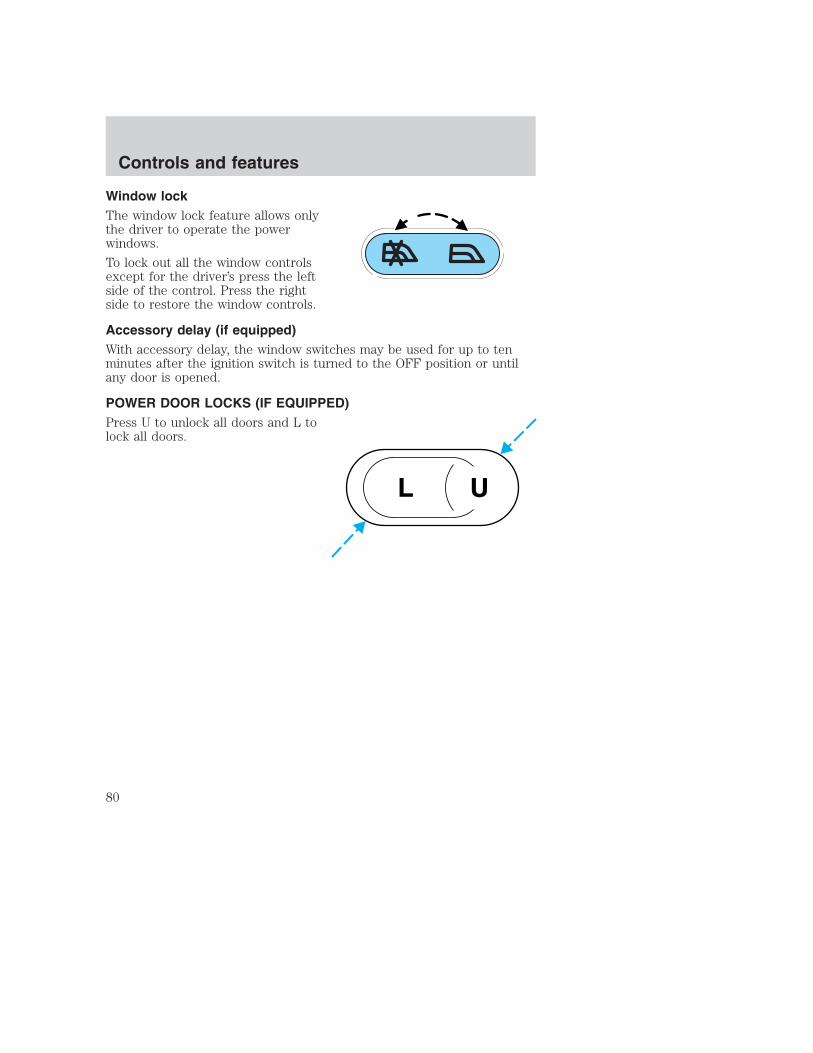
Window lockThe window lock feature allows onlythe driver to operate the powerwindows.
To lock out all the window controlsexcept for the driver’s press the leftside of the control. Press the rightside to restore the window controls.
Accessory delay (if equipped)With accessory delay, the window switches may be used for up to tenminutes after the ignition switch is turned to the OFF position or untilany door is opened.
POWER DOOR LOCKS (IF EQUIPPED)Press U to unlock all doors and L tolock all doors.
UL
Controls and features
80

CHILDPROOF DOOR LOCKSWhen these locks are set, the reardoors cannot be opened from theinside. The rear doors can beopened from the outside when thedoors are unlocked.
The childproof locks are located onrear edge of each rear door andmust be set separately for eachdoor. Setting the lock for one doorwill not automatically set the lockfor both doors.
Move lock control up to engage thechildproof lock. Move control downto disengage childproof locks.
POWER SIDE VIEW MIRRORS (IF EQUIPPED)The ignition can be in any position to adjust the power side view mirrors.
To adjust your mirrors:
1. Select L to adjust the left mirroror R to adjust the right mirror.
MIRRORS
L R
Controls and features
81

2. Move the control in the directionyou wish to tilt the mirror.
3. Return to the center position to lock mirrors in place.
4. Adjust spotter mirrors (if equipped) manually.
Fold-away mirrors
Fold the side mirrors in carefully when driving through a narrow space,like an automatic car wash.
The telescoping feature (if equipped) allows the mirror to extendapproximately 76 mm (3 inches).
MIRRORS
L R
Controls and features
82

Heated outside mirrors (if equipped)Both mirrors are heatedautomatically to remove ice, mistand fog when the rear windowdefrost is activated.
Do not remove ice from the mirrorswith a scraper or attempt toreadjust the mirror glass if it isfrozen in place. These actions couldcause damage to the glass andmirrors.
ILLUMINATED VISOR MIRROR (IF EQUIPPED)To turn on the visor mirror lamps,lift the mirror cover open.
CENTER CONSOLE (IF EQUIPPED)Your vehicle may be equipped with a variety of console features. Theseinclude:
• Utility compartment withcassette/CD holder
• Coin holder
• Pen holder
• Writing surface
Controls and features
83

• Utility compartment
• Coin holder
• Pen holder
• Writing surface
• Space for lap-top computer
REMOTE ENTRY SYSTEM (IF EQUIPPED)This device complies with part 15 of the FCC rules and with RS-210 ofIndustry Canada. Operation is subject to the following two conditions:(1) This device may not cause harmful interference, and (2) This devicemust accept any interference received, including interference that maycause undesired operation.
Changes or modifications not expressly approved by the partyresponsible for compliance could void the user’s authority tooperate the equipment.
The remote entry system allows you to lock or unlock all vehicle doorswithout a key.
The remote entry features only operate with the ignition in the LOCKposition.
If there is any potential remote keyless entry problem with your vehicle,ensure ALL key fobs (remote entry transmitters) are brought to thedealership, to aid in troubleshooting.
Controls and features
84

Unlocking the doorsPress this control to unlock thedriver’s door. The interior lamps willilluminate.
Press the control a second timewithin five seconds to unlock alldoors.
Locking the doorsPress this control to lock all doors.
To confirm all doors are closed andlocked, press the control a secondtime within five seconds. The doorswill lock again, the horn will chirpand the lamps will flash.
If any of the doors are ajar, the hornwill make two quick chirps,reminding you to properly close alldoors.
Sounding a panic alarmPress this control to activate thealarm.
To deactivate the alarm, press thecontrol again or turn the ignition toACC or ON.
Panic alarm will only operate withthe ignition in the OFF position.
Controls and features
85
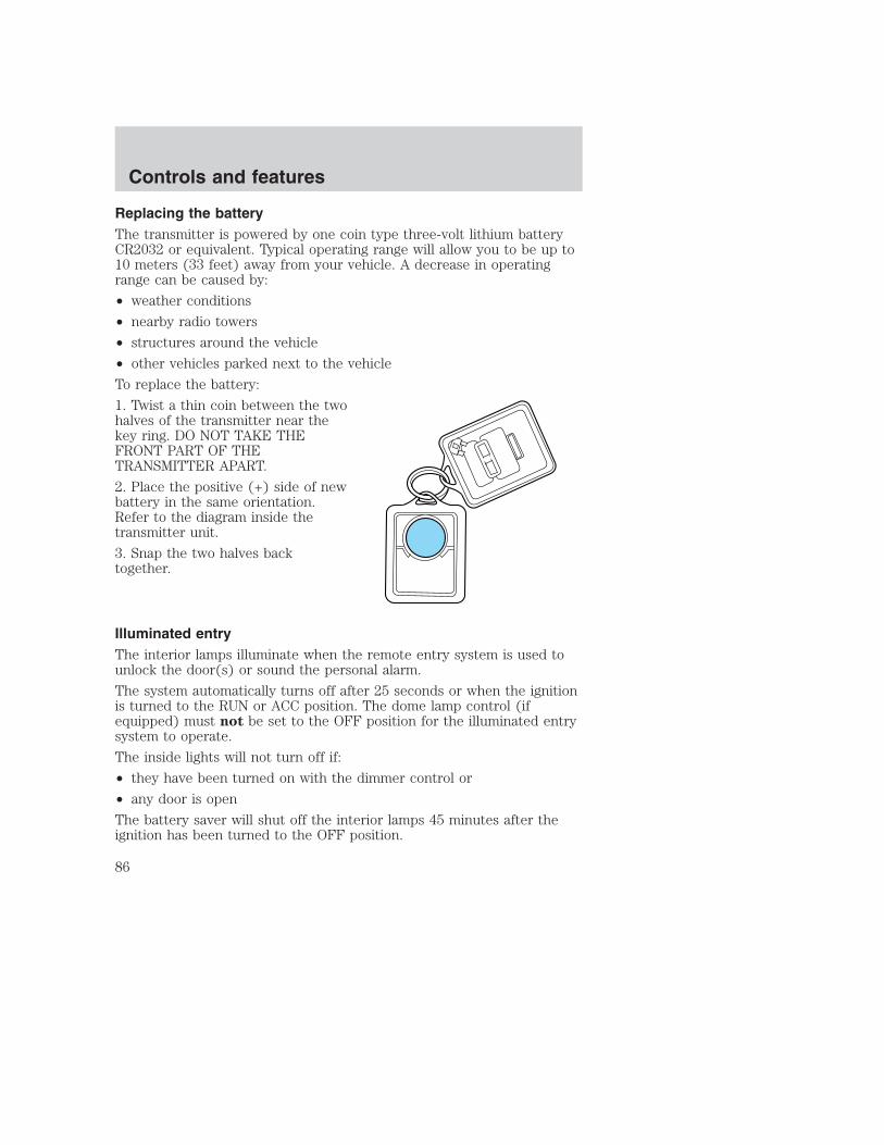
Replacing the batteryThe transmitter is powered by one coin type three-volt lithium batteryCR2032 or equivalent. Typical operating range will allow you to be up to10 meters (33 feet) away from your vehicle. A decrease in operatingrange can be caused by:
• weather conditions
• nearby radio towers
• structures around the vehicle
• other vehicles parked next to the vehicle
To replace the battery:
1. Twist a thin coin between the twohalves of the transmitter near thekey ring. DO NOT TAKE THEFRONT PART OF THETRANSMITTER APART.
2. Place the positive (+) side of newbattery in the same orientation.Refer to the diagram inside thetransmitter unit.
3. Snap the two halves backtogether.
Illuminated entryThe interior lamps illuminate when the remote entry system is used tounlock the door(s) or sound the personal alarm.
The system automatically turns off after 25 seconds or when the ignitionis turned to the RUN or ACC position. The dome lamp control (ifequipped) must not be set to the OFF position for the illuminated entrysystem to operate.
The inside lights will not turn off if:
• they have been turned on with the dimmer control or
• any door is open
The battery saver will shut off the interior lamps 45 minutes after theignition has been turned to the OFF position.
Controls and features
86

Replacing lost transmittersIf a remote transmitter has been lostand you would like to remove itfrom the vehicle’s memory, or youwould like to purchase additionalremote transmitters and have themprogrammed to your vehicle:
• Take all your vehicle’stransmitters to your dealer forprogramming, or
• Perform the programmingprocedure yourself
Programming remote transmittersIt is necessary to have all (maximum of four — original and/or new) ofyour remote transmitters available prior to beginning this procedure.
To program the transmitters yourself:
• Place the key in the ignition andturn from 2 (LOCK) to 3 (OFF)and cycle between 3 (OFF) and4(ON) eight times in rapidsuccession (within 10 seconds)with the eighth turn ending in the4 (ON) position. The doors willlock/unlock to confirm thatprogramming mode has beenentered.
• Within 20 seconds, program a remote transmitter by pressing anybutton on a transmitter. The doors will lock/unlock to confirm that theremote transmitter has been programmed. (If more than 20 secondspass before pressing a remote transmitter button, the programmingmode will exit and the procedure will have to be repeated.)
• Repeat the previous step to program additional remote transmitters.The doors will lock/unlock to confirm that each remote transmitter hasbeen programmed.
• When you have completed programming the remote transmitters, turnthe ignition to 3 (OFF) or wait 20 seconds. Again the doors willlock/unlock to confirm programming has been completed.
3
1
2
5
4
Controls and features
87

TAILGATE LOCK (IF EQUIPPED)Your vehicle may be equipped with atailgate lock designed to preventtheft of the tailgate.
• Insert ignition key and turn to theright to engage lock.
• Turn ignition key to the left tounlock.
TAILGATE REMOVALYour tailgate is removable to allowmore room for loading.
1. Lower the tailgate.
2. Use a screwdriver to pry thespring clip (on each connector) pastthe head of the support screw.Disconnect cable.
3. Disconnect the other cable.
4. Lift tailgate to a 45 degree angle.
5. Lift right side off of its hinge.
6. Lift left side off of its hinge.
To install, follow the removalprocedures in reverse order.
Controls and features
88

SEATING
Full bench seat (if equipped)• Lift the track release bar to move
the seat forward or backward.Ensure that the seat is relatchedinto place.
• Pull up on the release leverlocated at the bottom of theseatback to quickly fold theseatback forward.
40/20/40 split bench seat (if equipped)• Lift the track release bar to move
the seat forward or backward.Ensure the seat is relatched intoplace.
• Pull the seatback handle up torecline the seat.
• Push down the release leverlocated at the bottom of theseatback to quickly fold theseatback forward.
Seating and safety restraints
89

Captain’s chair (if equipped)• Lift the track release bar to move
the seat forward or rearward.Make sure that the seat isrelatched into place.
• Pull the release lever handlelocated on the side of the seat upto move the seat back forward orbackward.
• Push down the release lever (ifequipped) located at the bottomof the seatback to quickly fold theseatback forward.
Adjusting the front power seat (if equipped)
Never adjust the driver’s seat or seatback when the vehicle ismoving.
Do not pile cargo higher than the seatbacks to avoid injuringpeople in a collision or sudden stop.
Always drive and ride with your seatback upright and the lapbelt snug and low across the hips.
Reclining the seatback can reduce the effectiveness of the seat’ssafety belt in the event of a collision.
The control is located on the outboard side of the seat cushion.
Seating and safety restraints
90

Press to raise or lower the frontportion of the seat cushion.
Press to raise or lower the rearportion of the seat cushion.
Press the control to move the seatforward, backward, up or down.
Using the manual lumbar supportTurn the lumbar support controltoward the front of vehicle to movethe lumbar support forward formore direct support.
Turn the lumbar support controltoward the rear of vehicle to movethe lumbar support back for lessdirect support.
Seating and safety restraints
91

Heated seats (if equipped)To operate the heated seats:
• Push control to activate.
• Push again to deactivate.
The indicator light on the control will illuminate when activated.
FOLDING UP THE REAR SEATS(IF EQUIPPED — SUPERCAB ONLY)The rear seatback has a split 60/40 seat. Each seat cushion can beflipped up into the seatback position.
1. Pull control to release seatcushion.
2. Rotate seat cushion up until itlocks into vertical storage position.
Seating and safety restraints
92

RETURNING THE SEAT TO SEATING POSITION
Always be sure that the seat is in a latched position, whether theseat is occupied or empty. If not latched, the seat may cause
injury during a sudden stop.
1. Pull control on the side of the seat to release seat cushion fromstorage position.
2. Push seat cushion down until it locks into horizontal position.
SAFETY RESTRAINTS
Safety restraints precautions
Always drive and ride with your seatback upright and the lapbelt snug and low across the hips.
To reduce the risk of injury, make sure children sit where theycan be properly restrained.
Never let a passenger hold a child on his or her lap while thevehicle is moving. The passenger cannot protect the child from
injury in a collision.
All occupants of the vehicle, including the driver, should alwaysproperly wear their safety belts, even when an air bag SRS is
provided.
It is extremely dangerous to ride in a cargo area, inside oroutside of a vehicle. In a collision, people riding in these areas
are more likely to be seriously injured or killed. Do not allow people toride in any area of your vehicle that is not equipped with seats andsafety belts. Be sure everyone in your vehicle is in a seat and using asafety belt properly.
In a rollover crash, an unbelted person is significantly more likelyto die than a person wearing a safety belt.
Seating and safety restraints
93

Each seating position in your vehicle has a specific safety beltassembly which is made up of one buckle and one tongue that
are designed to be used as a pair. 1) Use the shoulder belt on theoutside shoulder only. Never wear the shoulder belt under the arm. 2)Never swing the safety belt around your neck over the inside shoulder.3) Never use a single belt for more than one person.
Always transport children 12 years old and under in the backseat and always properly use appropriate child restraints.
Combination lap and shoulder belts1. Insert the belt tongue into theproper buckle (the buckle closest tothe direction the tongue is comingfrom) until you hear a snap and feelit latch. Make sure the tongue issecurely fastened in the buckle.
2. To unfasten, push the releasebutton and remove the tongue fromthe buckle.
Seating and safety restraints
94

The front and rear outboard safety restraints in the vehicle arecombination lap and shoulder belts. The front passenger and rear seatoutboard safety belts have two types of locking modes described below:
Vehicle sensitive modeThe vehicle sensitive mode is the normal retractor mode, allowing freeshoulder belt length adjustment to your movements and locking inresponse to vehicle movement. For example, if the driver brakessuddenly or turns a corner sharply, or the vehicle receives an impact ofapproximately 8 km/h (5 mph) or more, the combination safety belts willlock to help reduce forward movement of the driver and passengers.
On SuperCab and CrewCab models, the front seat belt system can alsobe made to lock manually by quickly pulling on the shoulder belt.
Rear seat belts (if equipped) cannot be made to lock up by pullingquickly on the belt.
Automatic locking modeIn this mode, the shoulder belt is automatically pre-locked. The belt willstill retract to remove any slack in the shoulder belt.
The automatic locking mode is not available on the driver safety belt.
When to use the automatic locking mode• Any time a child safety seat is installed in a passenger front or
outboard rear seating position (if equipped). Children 12 years old andunder should be properly restrained in the rear seat wheneverpossible. Refer to Safety Restraints for Children or Safety Seats forChildren later in this chapter.
Seating and safety restraints
95

How to use the automatic locking mode• Buckle the combination lap and
shoulder belt.
• Grasp the shoulder portion andpull downward until the entirebelt is extracted.
• Allow the belt to retract. As the belt retracts, you will hear a clickingsound. This indicates the safety belt is now in the automatic lockingmode.
Seating and safety restraints
96

How to disengage the automatic locking mode
Ford recommends that all safety belt assemblies and attachinghardware should be inspected by a qualified technician after any
collision. Safety belt assemblies not in use during a collision should alsobe inspected and replaced if either damage or improper operation isnoted.
Disconnect the combination lap/shoulder belt and allow it to retractcompletely to disengage the automatic locking mode and activate thevehicle sensitive (emergency) locking mode.
After any vehicle collision, the front passenger outboard seat beltsystem must be checked by a qualified technician to verify that
the “automatic locking retractor” feature for child seats is stillfunctioning properly. In addition, all seat belts should be checked forproper function.
BELT AND RETRACTOR ASSEMBLY MUST BE REPLACED ifthe seat belt assembly “automatic locking retractor” feature or
any other seat belt function is not operating properly when checkedaccording to the procedures in Workshop Manual.
Failure to replace the Belt and Retractor assembly couldincrease the risk of injury in collisions.
Energy Management Feature• This vehicle has a seat belt system with an energy management
feature at the front outboard seating position to help further reducethe risk of injury in the event of a head-on collision.
• The front outboard seat belt system has a retractor assembly that isdesigned to pay out webbing in a controlled manner. This feature isdesigned to help reduce the belt force acting on the occupant’s chest.
Seating and safety restraints
97
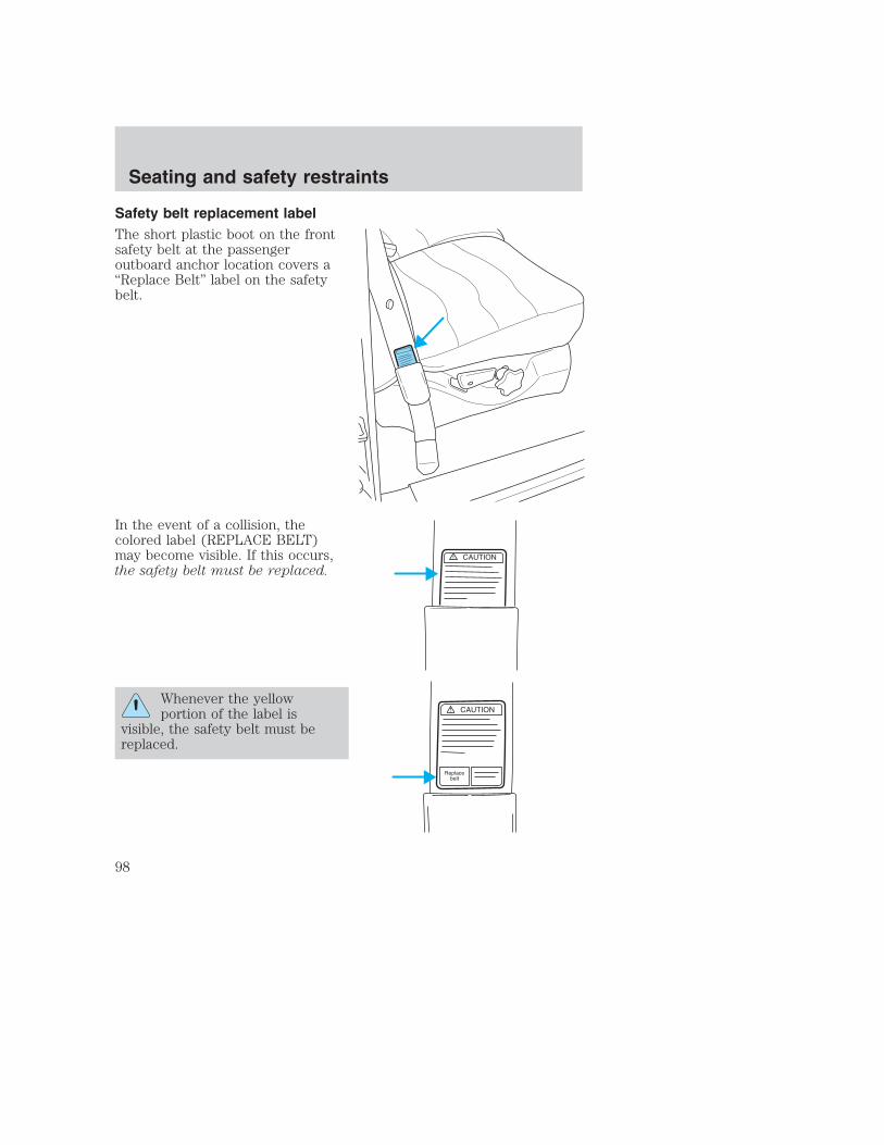
Safety belt replacement labelThe short plastic boot on the frontsafety belt at the passengeroutboard anchor location covers a“Replace Belt” label on the safetybelt.
In the event of a collision, thecolored label (REPLACE BELT)may become visible. If this occurs,the safety belt must be replaced.
Whenever the yellowportion of the label is
visible, the safety belt must bereplaced.
Seating and safety restraints
98

Failure to follow these instructions will affect the performance ofthe safety belts and increase the risk of personal injury.
Safety belt pretensionerYour vehicle may be equipped with safety belt pretensioners at the driverand front outboard passenger seating positions.
The Seat Integrated Restraints (SIR) seat is equipped with a bucklepretensioner. Do NOT place objects between the seats, this couldinterfere with the functioning of the pretensioner. For the SuperCab andCrewCab base bench seats and all Regular Cab seating positions, theseatbelts are equipped with a retractor pretensioner.
The safety belt pretensioners are designed to activate only during certainfrontal or near-frontal collisions with sufficient longitudinal deceleration.A safety belt pretensioner is a device which tightens the webbing of thelap and shoulder belts in such a way that they fit more snugly againstthe body.
The driver and front outboard passenger safety belt system (includingretractors, buckles and height adjusters) must be replaced if the vehicleis involved in a collision that results in the activation of the safety beltpretensioners. Refer to the Safety belt maintenance section in thischapter.
Failure to replace the safety belt assembly under the aboveconditions could result in severe personal injuries in the event of
a collision.
Front safety belt height adjustmentIf your vehicle has seat integrated restraints you will not have safety beltheight adjustments.
Your vehicle may have safety belt height adjustments for the driver andfront passenger. Adjust the height of the shoulder belt so the belt restsacross the middle of your shoulder.
Seating and safety restraints
99

• Regular Cab and 4–door CrewCab
• 4–door Super Cab (if equipped)
Seating and safety restraints
100
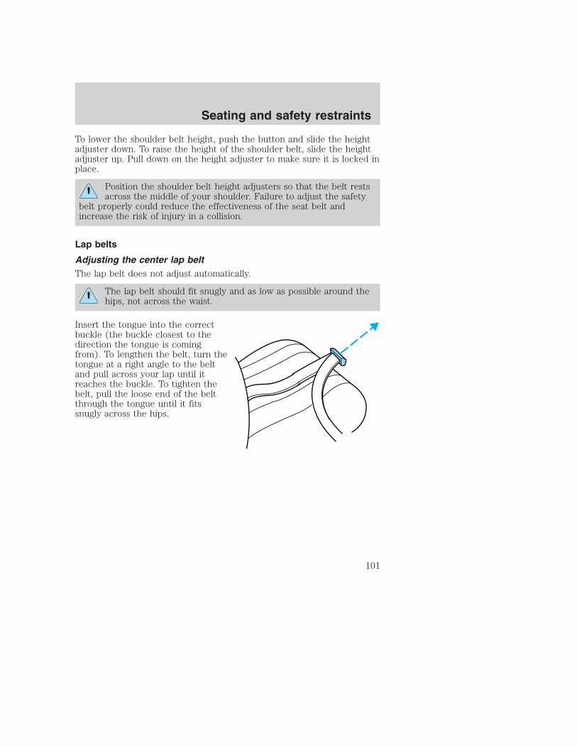
To lower the shoulder belt height, push the button and slide the heightadjuster down. To raise the height of the shoulder belt, slide the heightadjuster up. Pull down on the height adjuster to make sure it is locked inplace.
Position the shoulder belt height adjusters so that the belt restsacross the middle of your shoulder. Failure to adjust the safety
belt properly could reduce the effectiveness of the seat belt andincrease the risk of injury in a collision.
Lap belts
Adjusting the center lap beltThe lap belt does not adjust automatically.
The lap belt should fit snugly and as low as possible around thehips, not across the waist.
Insert the tongue into the correctbuckle (the buckle closest to thedirection the tongue is comingfrom). To lengthen the belt, turn thetongue at a right angle to the beltand pull across your lap until itreaches the buckle. To tighten thebelt, pull the loose end of the beltthrough the tongue until it fitssnugly across the hips.
Seating and safety restraints
101

Shorten and fasten the belt whennot in use.
Safety belt extension assemblyIf the safety belt is too short when fully extended, there is a 20 cm (8inch) safety belt extension assembly that can be added (part number611C22). This assembly can be obtained from your dealer at no cost.
Use only extensions manufactured by the same supplier as the safetybelt. Manufacturer identification is located at the end of the webbing onthe label. Also, use the safety belt extension only if the safety belt is tooshort for you when fully extended. Do not use extensions to change thefit of the shoulder belt across the torso.
Safety belt warning light and indicator chimeThe seat belt warning light illuminates in the instrument cluster and achime sounds to remind the occupants to fasten their safety belts.
Conditions of operation
If... Then...
The driver’s safety belt is notbuckled before the ignition switchis turned to the ON position...
The safety belt warning lightilluminates 1-2 minutes and thewarning chime sounds 4-8seconds.
The driver’s safety belt is buckledwhile the indicator light isilluminated and the warning chimeis sounding...
The safety belt warning light andwarning chime turn off.
The driver’s safety belt is buckledbefore the ignition switch is turnedto the ON position...
The safety belt warning light andindicator chime remain off.
Seating and safety restraints
102
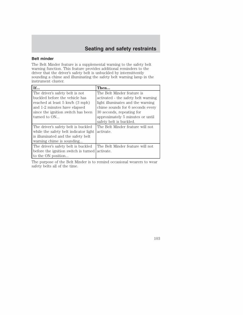
Belt minderThe Belt Minder feature is a supplemental warning to the safety beltwarning function. This feature provides additional reminders to thedriver that the driver’s safety belt is unbuckled by intermittentlysounding a chime and illuminating the safety belt warning lamp in theinstrument cluster.
If... Then...
The driver’s safety belt is notbuckled before the vehicle hasreached at least 5 km/h (3 mph)and 1-2 minutes have elapsedsince the ignition switch has beenturned to ON...
The Belt Minder feature isactivated - the safety belt warninglight illuminates and the warningchime sounds for 6 seconds every30 seconds, repeating forapproximately 5 minutes or untilsafety belt is buckled.
The driver’s safety belt is buckledwhile the safety belt indicator lightis illuminated and the safety beltwarning chime is sounding...
The Belt Minder feature will notactivate.
The driver’s safety belt is buckledbefore the ignition switch is turnedto the ON position...
The Belt Minder feature will notactivate.
The purpose of the Belt Minder is to remind occasional wearers to wearsafety belts all of the time.
Seating and safety restraints
103

The following are reasons most often given for not wearing safety belts:(All statistics based on U.S. data)
Reasons given... Consider...
“Crashes are rareevents”
36 700 crashes occur every day. The more wedrive, the more we are exposed to “rare” events,even for good drivers. 1 in 4 of us will beseriously injured in a crash during our lifetime.
“I’m not going far” 3 of 4 fatal crashes occur within 25 miles of home.“Belts areuncomfortable”
We design our safety belts to enhance comfort. Ifyou are uncomfortable - try different positions forthe safety belt upper anchorage and seatbackwhich should be as upright as possible; this canimprove comfort.
“I was in a hurry” Prime time for an accident. Belt Minder remindsus to take a few seconds to buckle up.
“Seat belts don’twork”
Safety belts, when used properly, reduce risk ofdeath to front seat occupants by 45% in cars,and by 60% in light trucks.
“Traffic is light” Nearly 1 of 2 deaths occur in single-vehiclecrashes, many when no other vehicles are around.
“Belts wrinkle myclothes”
Possibly, but a serious crash can do much morethan wrinkle your clothes, particularly if you areunbelted.
“The people I’mwith don’t wearbelts”
Set the example, teen deaths occur 4 times moreoften in vehicles with TWO or MORE people.Children and younger brothers/sisters imitatebehavior they see.
“I have an air bag” Air bags offer greater protection when used withsafety belts. Frontal airbags are not designed toinflate in rear and side crashes or rollovers.
“I’d rather bethrown clear”
Not a good idea. People who are ejected are 40times more likely to DIE. Safety belts helpprevent ejection, WE CAN’T “PICK OUR CRASH”.
Do not sit on top of a buckled safety belt to avoid the BeltMinder chime. Sitting on the safety belt will increase the risk of
injury in an accident. To disable (one-time) or deactivate the BeltMinder feature please follow the directions stated below.
Seating and safety restraints
104

One time disableAny time the safety belt is buckled and then unbuckled during anignition ON cycle, Belt Minder will be disabled for that ignition cycleonly.
Deactivating/activating the belt minder featureRead steps 1 - 9 thoroughly before proceeding with thedeactivation/activation programming procedure.
The Belt Minder feature can be deactivated/activated by performing thefollowing procedure:
Before following the procedure, make sure that:
• The parking brake is set.
• The gearshift is in P (Park) (automatic transmission) or the neutralposition (manual transmission).
• The ignition switch is in the OFF position.
• All vehicle doors are closed.
• The driver’s safety belt is unbuckled.
• The parklamps/headlamps are in OFF position (If vehicle is equippedwith Autolamps, this will not affect the procedure).
To reduce the risk of injury, do not deactivate/activate the BeltMinder feature while driving the vehicle.
1. Turn the ignition switch to the RUN (or ON) position. (DO NOTSTART THE ENGINE.)
2. Wait until the safety belt warning light turns off. (Approximately 1–2minutes.)
• Steps 3–5 must be completed within 60 seconds or the procedure willhave to be repeated.
3. Buckle then unbuckle the safety belt three times, ending with thesafety belt unbuckled. This can be done before or during Belt Minderwarning activation.
4. Turn on the parklamps/headlamps, turn off the parklamps/headlamps.
5. Buckle then unbuckle the safety belt three times, ending with thesafety belt unbuckled.
Seating and safety restraints
105

• After step 5 the safety belt warning light will be turned on for threeseconds.
6. Within seven seconds of the safety belt warning light turning off,buckle then unbuckle the safety belt.• This will disable Belt Minder if it is currently enabled, or enable Belt
Minder if it is currently disabled.
7. Confirmation of disabling Belt Minder is provided by the safety beltwarning light flashing four times per second for three seconds.
8. Confirmation of enabling Belt Minder is provided by:• The safety belt warning light flashing four times per second for three
seconds.• Followed by three seconds with the safety belt warning light off.• Once again, the safety belt warning light will flash four times per
second for three seconds.
9. After receiving confirmation, the deactivation/activation procedure iscomplete.
Safety belt maintenanceInspect the safety belt systems periodically to make sure they workproperly and are not damaged. Inspect the safety belts to make sure thereare no nicks, tears or cuts. Replace if necessary. All safety belt assemblies,including retractors, buckles, front seat belt buckle assemblies, bucklesupport assemblies (slide bar-if equipped), shoulder belt height adjusters(if equipped), shoulder belt guide on seatback (if equipped), child safetyseat tether bracket assemblies (if equipped), LATCH child seat tetheranchors and lower anchors (if equipped), and attaching hardware, shouldbe inspected after a collision. Ford recommends that all safety beltassemblies used in vehicles involved in a collision be replaced. However, ifthe collision was minor and a qualified technician finds that the belts donot show damage and continue to operate properly, they do not need to bereplaced. Safety belt assemblies not in use during a collision should also beinspected and replaced if either damage or improper operation is noted.
Failure to inspect and if necessary replace the safety beltassembly under the above conditions could result in severe
personal injuries in the event of a collision.
Refer to Cleaning and maintaining the safety belts in theMaintenacne and Care section.
Seating and safety restraints
106

AIR BAG SUPPLEMENTAL RESTRAINT SYSTEM (SRS)
Your vehicle is equipped with a crash sensing and diagnostic modulewhich records information about the air bag and sensor systems. In theevent of a collision this module may save information related to thecollision including information about the air bag system and impactseverity. This information will assist Ford in the servicing of your vehicleand may help Ford better understand real world collisions and furtherimprove the safety of future vehicles.
Important supplemental restraint system (SRS) precautionsThe supplemental restraint systemis designed to work with the safetybelt to help protect the driver andright front passenger from certainupper body injuries.
Air bags DO NOT inflate slowly orgently and the risk of injury from adeploying air bag is greatest close tothe trim covering the air bagmodule.
All occupants of the vehicle, including the driver, should alwaysproperly wear their safety belts, even when an air bag SRS is
provided.
1 2 3 4 5 6
DOLBY B NRDOLBY B NR
FM1 STST
O
SCAN EJ
REW FF SIDE 1-2 COMP SHUFFLE
TAPE CDDISCS
BASS TREB BAL FADE AUTOSET
VOL - PUSH ON
SEEKTUNE
AMFM
18
P
A/C
MAXA/C
OFF
40
30
20H
H 100
50 6070
801
23
490
100
40
20
6080 100
120
140
160 MPH
DIESEL FUEL ONLY
RPM x 1000 km/h
F
ON
OFF
RES
SETACCEL
COAST
Seating and safety restraints
107

Always transport children 12 years old and under in the backseat and always properly use appropriate child restraints.
National Highway Traffic Safety Administration (NHTSA)recommends a minimum distance of at least 25 cm (10 inches)
between an occupant’s chest and the driver air bag module.
Never place your arm over the air bag module as a deploying airbag can result in serious arm fractures or other injuries.
Steps you can take to properly position yourself away from the air bag:
• Move your seat to the rear as far as you can while still reaching thepedals comfortably.
• Recline the seat slightly (one or two degrees) from the uprightposition.
Do not put anything on or over the air bag module. Placingobjects on or over the air bag inflation area may cause those
objects to be propelled by the air bag into your face and torso causingserious injury.
Do not attempt to service, repair, or modify the air bagsupplemental restraint systems or its fuses. Se your Ford or
Lincoln Mercury dealer.
Modifications to the front end of the vehicle, including frame,bumper, front end body structure and tow hooks may affect the
performance of the air bag sensors increasing the risk of injury. Do notmodify the front end of the vehicle.
Additional equipment such as snowplow equipment may effectthe performance of the air bag sensors increasing the risk of
injury. Please refer to the Body Builders Layout Book for instructionsabout the appropriate installation of additional equipment.
Seating and safety restraints
108

Removing the blocker beam without installing snow plowattachment hardware may effect air bag deployment in a crash.
Do not operate the truck unless either the blocker beam or snow plowattachment hardware is installed on the vehicle.
Children and air bagsFor additional important safety information, read all information onsafety restraints in this guide.
Children must always be properly restrained. Failure to follow theseinstructions may increase the risk of injury in a collision.
An infant in a rear-facing seat faces a high risk of serious or fatalinjuries from a deploying passenger air bag. Rear facing infant
seats should NEVER be placed in the front seats, unless the passengerair bag is turned off. See Passenger air bag ON/OFF switch.
How does the air bag supplemental restraint system work?The air bag SRS is designed toactivate when the vehicle sustainssufficient longitudinal deceleration.
The fact that the air bags did notinflate in a collision does not meanthat something is wrong with thesystem. Rather, it means the forceswere not of the type sufficient tocause activation. Air bags aredesigned to inflate in frontal andnear-frontal collisions, not rollover,side-impact, or rear-impacts.
Seating and safety restraints
109

The air bags inflate and deflaterapidly upon activation. After air bagdeployment, it is normal to notice asmoke-like, powdery residue orsmell the burnt propellant. This mayconsist of cornstarch, talcumpowder (to lubricate the bag) orsodium compounds (e.g., bakingsoda) that result from thecombustion process that inflates theair bag. Small amounts of sodiumhydroxide may be present whichmay irritate the skin and eyes, butnone of the residue is toxic.
While the system is designed to helpreduce serious injuries, it may alsocause minor abrasions, swelling or temporary hearing loss. Because airbags must inflate rapidly and with considerable force, there is the risk ofdeath or serious injuries such as fractures, facial and eye injuries orinternal injuries, particularly to occupants who are not properlyrestrained or are otherwise out of position at the time of air bagdeployment. Thus, it is extremely important that occupants be properlyrestrained as far away from the air bag module as possible whilemaintaining vehicle control.
Several air bag system components get hot after inflation. Do nottouch them after inflation.
If the air bag has deployed, the air bag will not functionagain and must be replaced immediately. If the air bag is not
replaced, the unrepaired area will increase the risk of injury in acollision.
The SRS consists of:
• driver and passenger (if equipped) air bag modules (which include theinflators and air bags),
• one or more impact and safing sensors,
• a readiness light and tone
• and the electrical wiring which connects the components.
Seating and safety restraints
110

The diagnostic module monitors its own internal circuits and thesupplemental air bag electrical system warning (including the impactsensors), the system wiring, the air bag system readiness light, the airbag back up power and the air bag ignitors.
Determining if the system is operationalThe SRS uses a readiness light in the instrument cluster or a tone toindicate the condition of the system. Refer to the Air bag readinesssection in the Instrumentation chapter. Routine maintenance of the airbag is not required.
A difficulty with the system is indicated by one or more of the following:
• The readiness light will eitherflash or stay lit.
• The readiness light will notilluminate immediately afterignition is turned on.
• A series of five beeps will be heard. The tone pattern will repeatperiodically until the problem and/or light are repaired.
If any of these things happen, even intermittently, have the SRS servicedat your dealership or by a qualified technician immediately. Unlessserviced, the system may not function properly in the event of acollision.
Disposal of air bags and air bag equipped vehicles(including pretensioners)For disposal of air bags or air bag equipped vehicles, see your localdealership or qualified technician. Air bags MUST BE disposed of byqualified personnel.
Seating and safety restraints
111

Passenger air bag ON/OFF switch (if equipped)
An air bag ON/OFF switchhas been installed in this
vehicle. Before driving, alwayslook at the face of the switch tobe sure the switch is in the properposition in accordance with theseinstructions and warnings. Failureto put the switch in a properposition can increase the risk ofserious injury or death in acollision.
Turning the passenger air bag off1. Insert the ignition key, turn theswitch to OFF position and hold inOFF position while removing thekey.
2. When the ignition is turned to theON position the OFF lightilluminates briefly, momentarilyshuts off and then turns back on.This indicates that the passenger airbag is deactivated.
If the light fails to illuminate when the passenger air bag switchis in the OFF position and the ignition switch is in ON, have the
passenger air bag switch serviced at your Ford or Lincoln-Mercurydealer immediately.
In order to avoid inadvertent activation of the switch, alwaysremove the ignition key from the passenger air bag ON/OFF
switch.
PASSENGER AIR BAG
OFF
OFF
ON
PASSENGER AIR BAG
OFF
OFF
ON
Seating and safety restraints
112

Turning the passenger air bag back onThe passenger air bag remains OFF until you turn it back ON.
1. Insert the ignition key and turnthe switch to ON.
2. The OFF light will brieflyilluminate when the ignition isturned to On. This indicates that thepassenger air bag is operational.
If the light is illuminated when the passenger air bag switch is inthe ON position and the ignition switch is in ON, have the
passenger air bag switch serviced at your Ford or Lincoln-Mercurydealer immediately.
The passenger side air bag should always be ON (the air bag OFF lightshould not be illuminated) unless the passenger is a person who meetsthe requirements stated either in Category 1, 2 or 3 of theNHTSA/Transport Canada deactivation criteria which follows.
The safety belts for the driver and right front passenger seatingpositions have been specifically designed to function together
with the air bags in certain types of crashes. When you turn OFF yourair bag, you not only lose the protection of the air bag, you also mayreduce the effectiveness of your safety belt system, which wasdesigned to work with the air bag. If you are not a person who meetsthe requirements stated in the NHTSA/Transport Canada deactivationcriteria turning OFF the air bag can increase the risk of serious injuryor death in a collision.
Always transport children who are 12 and younger in the rearseat. Always use safety belts and child restraints properly. If a
child in a rear facing infant seat must be transported in front, thepassenger air bag must be turned OFF. This is because the back of theinfant seat is too close to the inflating air bag and the risk of a fatalinjury to the infant when the air bag inflates is substantial.
PASSENGER AIR BAG
OFF
OFF
ON
Seating and safety restraints
113

The vast majority of drivers and passengers are much safer with an airbag than without. To do their job and reduce the risk of life threateninginjuries, air bags must open with great force, and this force can pose apotentially deadly risk in some situations, particularly when a front seatoccupant is not properly buckled up. The most effective way to reducethe risk of unnecessary air bag injuries without reducing the overallsafety of the vehicle is to make sure all occupants are properlyrestrained in the vehicle, especially in the front seat. This provides theprotection of safety belts and permits the air bags to provide theadditional protection they were designed to provide. If you choose todeactivate your air bag, you are losing the very significant risk reducingbenefits of the air bag and you are also reducing the effectiveness of thesafety belts, because safety belts in modern vehicles are designed towork as a safety system with the air bags.
Read all air bag Warning labels in the vehicle as well as the otherimportant air bag instructions and Warnings in this Owner’s Guide.
NHTSA deactivation criteria (excluding Canada)1. Infant. An infant (less than 1 year old) must ride in the front seatbecause:
• the vehicle has no rear seat;
• the vehicle has a rear seat too small to accommodate a rear-facinginfant seat; or
• the infant has a medical condition which, according to the infant’sphysician, makes it necessary for the infant to ride in the front so thatthe driver can constantly monitor the child’s condition.
2. Child age 1 to 12. A child age 1 to 12 must ride in the front seatbecause:
• the vehicle has no rear seat;
• although children ages 1 to 12 ride in the rear seat(s) wheneverpossible, children ages 1 to 12 sometimes must ride in the frontbecause no space is available in the rear seat(s) of the vehicle; or
• the child has a medical condition which, according to the child’sphysician, makes it necessary for the child to ride in the front seat sothat the driver can constantly monitor the child’s condition.
Seating and safety restraints
114

3. Medical condition. A passenger has a medical condition which,according to his or her physician:
• causes the passenger air bag to pose a special risk for the passenger;and
• makes the potential harm from the passenger air bag in a crashgreater than the potential harm from turning OFF the air bag andallowing the passenger, even if belted, to hit the dashboard orwindshield in a crash.
This vehicle has special energy management safety belts for thedriver and/or right front passenger. These particular belts are
specifically designed to work with air bags to help reduce the risk ofinjury in a collision. The energy management safety belt is designed togive or release additional belt webbing in some accidents to reduceconcentration of force on an occupant’s chest and reduce the risk ofcertain bone fractures and injuries to underlying organs. In a crash, ifthe air bag is turned OFF, this energy management safety belt mightpermit the person wearing the belt to move forward enough to incur aserious or fatal injury. The more severe the crash, and the heavier theoccupant, the greater the risk is. Be sure the air bag is turned ON forany person who does not qualify under the NHTSA deactivationcriteria.
Transport Canada deactivation criteria (Canada Only)1. Infant: An infant (less than 1 year old) must ride in the front seatbecause:
• my vehicle has no rear seat;
• the rear seat in my vehicle cannot accommodate a rear-facing infantseat; or
• the infant has a medical condition which, according to the infant’sphysician, makes it necessary for the infant to ride in the front seat sothat the driver can monitor the infant’s condition.
2. Child age 12 or under: A child age 12 or under must ride in thefront seat because:
• my vehicle has no rear seat;
• although children age 12 and under ride in the rear seat wheneverpossible, children age 12 and under have no option but to sometimesride in the front seat because rear seat space is insufficient; or
Seating and safety restraints
115
• the child has a medical condition that, according to the child’sphysician, makes it necessary for the child to ride in the front seat sothat the driver can monitor the child’s condition.
3. Medical condition: A passenger has a medical condition that,according to his or her physician:
• poses a special risk for the passenger if the air bag deploys; and
• makes the potential harm from the passenger air bag deploymentgreater than the potential harm from turning OFF the air bag andexperiencing a crash without the protection offered by the air bag
This vehicle has special energy management safety belts for thedriver and/or right front passenger. These particular belts are
specifically designed to work with air bags to help reduce the risk ofinjury in a collision. The energy management safety belt is designed togive or release additional belt webbing in some accidents to reduceconcentration of force on an occupant’s chest and reduce the risk ofcertain bone fractures and injuries to underlying organs. In a crash, ifthe air bag is turned OFF, this energy management safety belt mightpermit the person wearing the belt to move forward enough to incur aserious or fatal injury. The more severe the crash, and the heavier theoccupant, the greater the risk is. Be sure the air bag is turned ON forany person who does not qualify under the Transport Canadadeactivation criteria.
SAFETY RESTRAINTS FOR CHILDRENSee the following sections for directions on how to properly use safetyrestraints for children. Also see Air Bag Supplemental RestraintSystem (SRS) in this chapter for special instructions about using airbags.
Important child restraint precautionsYou are required by law to use safety restraints for children in the U.S.and Canada. If small children ride in your vehicle (generally children whoare four years old or younger and who weigh 18 kg [40 lbs] or less), youmust put them in safety seats made especially for children. Check yourlocal and state or provincial laws for specific requirements regarding thesafety of children in your vehicle.
Seating and safety restraints
116

Never let a passenger hold a child on his or her lap while thevehicle is moving. The passenger cannot protect the child from
injury in a collision.
Always follow the instructions and warnings that come with any infant orchild restraint you might use.
When possible, always place children under age 12 in the rear seat ofyour vehicle. Accident statistics suggest that children are safer whenproperly restrained in the rear seating positions than in the front seatingposition.
Children and safety beltsIf the child is the proper size, restrain the child in a safety seat.
Children who are too large for child safety seats (as specified by yourchild safety seat manufacturer) should always wear safety belts.
Follow all the important safety restraint and air bag precautions thatapply to adult passengers in your vehicle.
If the shoulder belt portion of a combination lap and shoulder belt canbe positioned so it does not cross or rest in front of the child’s face orneck, the child should wear the lap and shoulder belt. Moving the childcloser to the center of the vehicle may help provide a good shoulder beltfit.
Do not leave children, unreliable adults, or pets unattended inyour vehicle.
To improve the fit of lap and shoulder belts on children who haveoutgrown child safety seats, Ford recommends use of a belt-positioningbooster seat that is labelled as conforming to all applicable Federal motorvehicle safety standards. Belt-positioning booster seats raise the childand provide a shorter, firmer seating cushion that encourages saferseating posture and better fit of lap and shoulder belts on the child.
A belt-positioning booster seat should be used if the shoulder belt restsin front of the child’s face or neck, or if the lap belt does not fit snuglyon both thighs, or if the thighs are too short to let the child sit all theway back on the seat cushion when the lower legs hang over the edge ofthe seat cushion. You may wish to discuss the special needs of your childwith your pediatrician.
Seating and safety restraints
117

SAFETY SEATS FOR CHILDREN
Child and infant or child safety seatsUse a safety seat that is recommended for the size and weight of thechild. Carefully follow all of the manufacturer’s instructions with thesafety seat you put in your vehicle. If you do not install and use thesafety seat properly, the child may be injured in a sudden stop orcollision.
When installing a child safety seat:
• Review and follow the informationpresented in the Air BagSupplemental Restraint System(SRS) section in this chapter.
• Use the correct safety belt bucklefor that seating position (thebuckle closest to the direction thetongue is coming from).
• Insert the belt tongue into theproper buckle until you hear asnap and feel it latch. Make surethe tongue is securely fastened inthe buckle.
• Keep the buckle release buttonpointing up and away from thesafety seat, with the tonguebetween the child seat and therelease button, to prevent accidental unbuckling.
• Place seat back in upright position.
Seating and safety restraints
118

• Put the safety belt in the automatic locking mode. Refer to Automaticlocking mode (passenger side front and outboard rear seatingpositions) (if equipped) section in this chapter.
Ford recommends the use of a child safety seat having a top tetherstrap. Install the child safety seat in a seating position which is capableof providing a tether anchorage. For more information on top tetherstraps, refer to Attaching child safety seats with tether straps. in thischapter.
Carefully follow all of the manufacturer’s instructions includedwith the safety seat you put in your vehicle. If you do not install
and use the safety seat properly, the child may be injured in a suddenstop or collision.
Installing child safety seats in combination lap and shoulder beltseating positions1. Position the child safety seat in aseat with a combination lap andshoulder belt.
An air bag can kill or injure a child in a child seat. If you mustuse a forward-facing child seat in the front seat, move seat all
the way back.
An air bag can kill or injure a child in a child seat. Child seatsshould never be placed in the front seats, unless passenger air
bag switch is turned off, See Passenger air bag on/off switch.
Seating and safety restraints
119

Rear facing child seats should NEVER be placed in the frontseats unless the passenger airbag switch is turned off.
2. Pull down on the shoulder beltand then grasp the shoulder beltand lap belt together.
3. While holding the shoulder andlap belt portions together, route thetongue through the child seataccording to the child seatmanufacturer’s instructions. Be surethe belt webbing is not twisted.
4. Insert the belt tongue into theproper buckle (the buckle closest tothe direction the tongue is comingfrom) for that seating position untilyou hear and feel the latch engage.Make sure the tongue is latchedsecurely by pulling on it.
Seating and safety restraints
120

5. To put the retractor in theautomatic locking mode, grasp theshoulder portion of the belt and pulldownward until all of the belt isextracted and a click is heard.
6. Allow the belt to retract. The belt will click as it retracts to indicate itis in the automatic locking mode.
7. Pull the lap belt portion acrossthe child seat toward the buckle andpull up on the shoulder belt whilepushing down with knee on thechild seat.
8. Allow the safety belt to retract toremove any slack in the belt.
9. Before placing the child in theseat, forcibly tilt the seat forwardand back to make sure the seat issecurely held in place.
10. Try to pull the belt out of the retractor to make sure the retractor isin the automatic locking mode (you should not be able to pull more beltout). If the retractor is not locked, unbuckle the belt and repeat stepstwo through nine.
Check to make sure the child seat is properly secured before each use.
Seating and safety restraints
121

Attaching safety seats with tether strapsSome manufacturers make safety seats that include a tether strap thatgoes over the back of the vehicle seat and attaches to an anchoringpoint. Other manufacturers offer the tether strap as an accessory.Contact the manufacturer of your child safety seat for information aboutordering a tether strap.
Tether anchorage hardwareA tethered seat can be installed in the front seat. Put the tether strapover the seatback and attach it to an anchor bracket.
An anchor bracket can be installed to the inside of the back panel ofyour vehicle.
The anchor bracket must be installed using the instructions providedwith the tether anchorage hardware kit.
Tether anchorage hardware kits (part number 613D74) includinginstructions, may be obtained at no charge from any Ford orLincoln/Mercury dealer.
If you have a Super Cab or Crew Cab, Ford recommends you attachtether safety seats in the rear seating position (if possible) with thetether strap attached to the tether anchorage bracket as shown in theinstructions provided with the tether anchor kit.
Tighten the anchor according to specifications. Otherwise, thesafety seat may not be properly secured and the child may be
injured in a sudden stop or collision.
Attaching child safety seats with tether strapsMost new forward-facing child safety seats include a tether strap whichgoes over the back of the seat and hooks to an anchoring point. Tetherstraps are available as an accessory for many older safety seats. Contactthe manufacturer of your child seat for information about ordering atether strap.
The passenger seats of your vehicle may be equipped with built-in tetherstrap anchors located behind the seats as described below.
The tether anchors in your vehicle may be straps on the seatback or ananchor bracket on the rear edge of the seat cushion or an anchor bracketmounted to the body shell on the back panel.
Seating and safety restraints
122

The SuperCab rear seat has three straps behind the top of the seat backthat function as both routing loops for the tether straps and anchorloops.
The tether strap anchors in your vehicle are in the following positions(shown from top view):
Attach the tether strap only to the appropriate tether anchor asshown. The tether strap may not work properly if attached
somewhere other than the correct tether anchor.
• F—Series Regular Cab
• F—Series SuperCab
• F—Series Crew Cab
Tether strap attachment
1. Position the child safety seat on the seat cushion.
2. Route the child safety seat tether strap over the back of the seat.
3. Locate the correct anchor for the selected seating position.
Seating and safety restraints
123

4. You may need to pull the seatback forward to access the tetheranchors. Make sure the seat is locked in the upright position beforeinstalling the child seat. Refer to the Folding down the rear seatssection in this chapter for information on how to operate the rear seats.
5. Clip the tether strap to the anchor as shown.
• Front seat (SuperCab only)
• Front seats (Regular Cab) andRear seats (Crew Cab only)
If the tether strap is clipped incorrectly, the child safety seatmay not be retained properly in the event of a collision.
6. Refer to the Installing child safety seats in combination lap andshoulder belt seating positions section of this chapter for furtherinstructions to secure the child safety seat.
7. Tighten the child safety seat tether strap according to themanufacturer’s instructions.
If the safety seat is not anchored properly, the risk of a childbeing injured in a collision greatly increases.
Seating and safety restraints
124
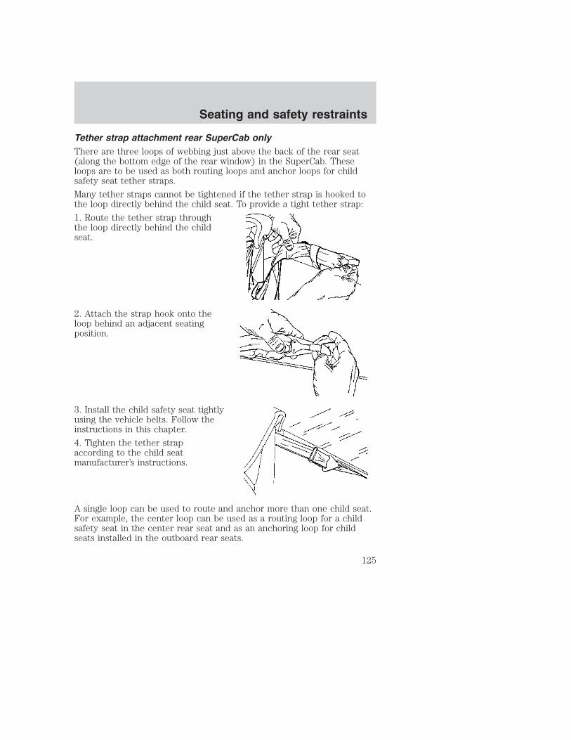
Tether strap attachment rear SuperCab onlyThere are three loops of webbing just above the back of the rear seat(along the bottom edge of the rear window) in the SuperCab. Theseloops are to be used as both routing loops and anchor loops for childsafety seat tether straps.
Many tether straps cannot be tightened if the tether strap is hooked tothe loop directly behind the child seat. To provide a tight tether strap:
1. Route the tether strap throughthe loop directly behind the childseat.
2. Attach the strap hook onto theloop behind an adjacent seatingposition.
3. Install the child safety seat tightlyusing the vehicle belts. Follow theinstructions in this chapter.
4. Tighten the tether strapaccording to the child seatmanufacturer’s instructions.
A single loop can be used to route and anchor more than one child seat.For example, the center loop can be used as a routing loop for a childsafety seat in the center rear seat and as an anchoring loop for childseats installed in the outboard rear seats.
Seating and safety restraints
125

PREPARING TO START YOUR VEHICLEEngine starting is controlled by the powertrain control system. Thissystem meets all Canadian Interference-Causing Equipment standardrequirements regulating the impulse electrical field strength of radionoise.
When starting a fuel-injected engine, avoid pressing the acceleratorbefore or during starting. Only use the accelerator when you havedifficulty starting the engine. For more information on starting thevehicle, refer to Starting the engine in this chapter.
Extended idling at high engine speeds can produce very hightemperatures in the engine and exhaust system, creating the risk
of fire or other damage.
Do not park, idle, or drive your vehicle in dry grass or other dryground cover. The emission system heats up the engine
compartment and exhaust system, which can start a fire.
Do not start your vehicle in a closed garage or in other enclosedareas. Exhaust fumes can be toxic. Always open the garage door
before you start the engine. See Guarding against exhaust fumes inthis chapter for more instructions.
If you smell exhaust fumes inside your vehicle, have your dealerinspect your vehicle immediately. Do not drive if you smell
exhaust fumes.
Important safety precautionsA computer system controls the engine’s idle revolutions per minute(RPM). When the engine starts, the idle RPM runs faster to warm theengine. If the engine idle speed does not slow down automatically, havethe vehicle checked. Do not allow the vehicle to idle for more than 10minutes at high engine RPM.
Before starting the vehicle:
1. Make sure all vehicle occupants have buckled their safety belts. Formore information on safety belts and their proper usage, refer to theSeating and safety restraints chapter.
Starting
126

2. Make sure the headlamps and vehicle accessories are off.
If starting a vehicle with an automatic transmission:
• Make sure the parking brake isset.
• Make sure the gearshift is in P (Park).
If starting a vehicle with a manual transmission:
• Make sure the parking brake is set.
• Push the clutch pedal to thefloor.
3. Turn the key to 4 (ON) withoutturning the key to 5 (START).
If there is difficulty in turning thekey, firmly rotate the steering wheelleft and right until the key turnsfreely. This condition may occurwhen:
• front wheels are turned
• front wheel is against the curb
• steering wheel is turned when getting in or out of the vehicle
1
2
34
5
Starting
127

Make sure the corresponding lights illuminate or illuminate briefly. If alight fails to illuminate, have the vehicle serviced.
• If the driver’s safety belt is fastened, the light may not illuminate.
STARTING THE ENGINENOTE: Whenever you start your vehicle, release the key as soon as theengine starts. Excessive cranking could damage the starter.
1. Turn the key to 5 (START)without pressing the acceleratorpedal and release as soon as theengine starts. The key will return to4 (ON).
2. If the temperature is above –12°C(10°F) and the engine does notstart within five seconds on the firsttry, turn the key to OFF, wait 10seconds and try again.
3. If the temperature is below -12° C (10° F) and the engine does notstart in 15 seconds on the first try, turn the key OFF and wait 10seconds and try again. If the engine does not start in two attempts, pressthe accelerator pedal all the way to floor and hold. Turn the key toSTART position.
4. When the engine starts, release the key, then release the acceleratorpedal gradually as the engine speeds up.
5. After idling for a few seconds, apply the brake and release the parkingbrake.
0
0 0 0 0
0 0 0 0 0
MPH
20
km/h
40
6080 100
120
140
160
010
20
30
4050 60
70
80
90
100
LOWFUEL
CRUISEABS
+ -
L
E
F
H
RPM 1000X0
1
23
5
6
4
P R N 2 18C
18
H
D
FUEL FILL
DOORAJAR
LOWRANGE 4 X 4
BRAKE
!SERVICEENGINESOON
3
2
1
5
4
Starting
128

Using the engine block heater (if equipped)An engine block heater warms theengine coolant, which improvesstarting, warms up the engine fasterand allows the heater-defrostersystem to respond quickly. Use of anengine block heater is stronglyrecommended if you live in a regionwhere temperatures reach -23°C(-10°F) or below.
For best results, plug the heater inat least three hours before starting the vehicle. Using the heater forlonger than three hours will not harm the engine, so the heater can beplugged in the night before starting the vehicle.
To prevent electrical shock, do not use your heater withungrounded electrical systems or two-pronged (cheater)
adapters.
Guarding against exhaust fumesAlthough odorless and colorless, carbon monoxide is present in exhaustfumes. Take precautions to avoid its dangerous effects.
If you ever smell exhaust fumes of any kind inside your vehicle,have your dealer inspect and fix your vehicle immediately. Do
not drive if you smell exhaust fumes. These fumes are harmful andcould kill you.
Have the exhaust and body ventilation systems checked whenever:
• the vehicle is raised for service
• the sound of the exhaust system changes
• the vehicle has been damaged in a collision
Starting
129
WARNING: Engine exhaust, some of its constituents, andcertain vehicle components contain or emit chemicals known to
the State of California to cause cancer and birth defects or otherreproductive harm. In addition, certain fluids contained in vehicles andcertain products of component wear contain or emit chemicals knownto the State of California to cause cancer and birth defects or otherreproductive harm.
Important ventilating informationIf the engine is idling while the vehicle is stopped in an open area forlong periods of time, open the windows at least 2.5 cm (one inch).
Adjust the heating or air conditioning (if equipped) to bring in fresh air.
Improve vehicle ventilation by keeping all air inlet vents clear of snow,leaves and other debris.
Starting
130
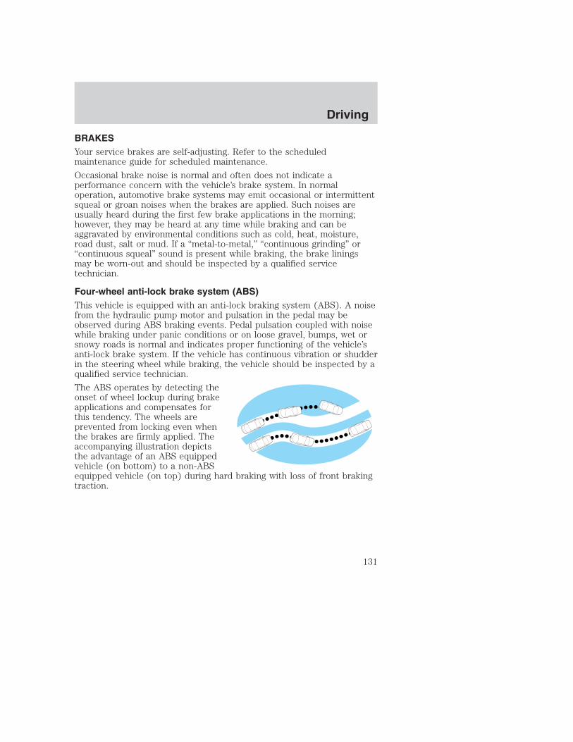
BRAKESYour service brakes are self-adjusting. Refer to the scheduledmaintenance guide for scheduled maintenance.
Occasional brake noise is normal and often does not indicate aperformance concern with the vehicle’s brake system. In normaloperation, automotive brake systems may emit occasional or intermittentsqueal or groan noises when the brakes are applied. Such noises areusually heard during the first few brake applications in the morning;however, they may be heard at any time while braking and can beaggravated by environmental conditions such as cold, heat, moisture,road dust, salt or mud. If a “metal-to-metal,” “continuous grinding” or“continuous squeal” sound is present while braking, the brake liningsmay be worn-out and should be inspected by a qualified servicetechnician.
Four-wheel anti-lock brake system (ABS)This vehicle is equipped with an anti-lock braking system (ABS). A noisefrom the hydraulic pump motor and pulsation in the pedal may beobserved during ABS braking events. Pedal pulsation coupled with noisewhile braking under panic conditions or on loose gravel, bumps, wet orsnowy roads is normal and indicates proper functioning of the vehicle’santi-lock brake system. If the vehicle has continuous vibration or shudderin the steering wheel while braking, the vehicle should be inspected by aqualified service technician.
The ABS operates by detecting theonset of wheel lockup during brakeapplications and compensates forthis tendency. The wheels areprevented from locking even whenthe brakes are firmly applied. Theaccompanying illustration depictsthe advantage of an ABS equippedvehicle (on bottom) to a non-ABSequipped vehicle (on top) during hard braking with loss of front brakingtraction.
Driving
131

Using four wheel ABS• In an emergency or when maximum efficiency from the four wheel
ABS is required, apply continuous force on the brake. The four wheelABS will be activated immediately, thus allowing you to retain fullsteering control of your vehicle and, providing there is sufficientspace, will enable you to avoid obstacles and bring the vehicle to acontrolled stop.
• The anti-lock system does not decrease the time necessary to applythe brakes or always reduce stopping distance. Always leave enoughroom between your vehicle and the vehicle in front of you to stop.
• We recommend that you familiarize yourself with this brakingtechnique. However, avoid taking any unnecessary risks.
ABS warning lamp ABS
The ABS warning lamp in the instrument cluster momentarily illuminateswhen the ignition is turned to the ON position. If the light does notilluminate momentarily at start up, remains on or continues to flash, theABS needs to be serviced.
With the ABS light on, the anti-lockbrake system is disabled and normalbraking is still effective unless thebrake warning light also remainsilluminated with parking brakereleased. (If your brake warning lamp illuminates, have your vehicleserviced immediately.)
Driving
132
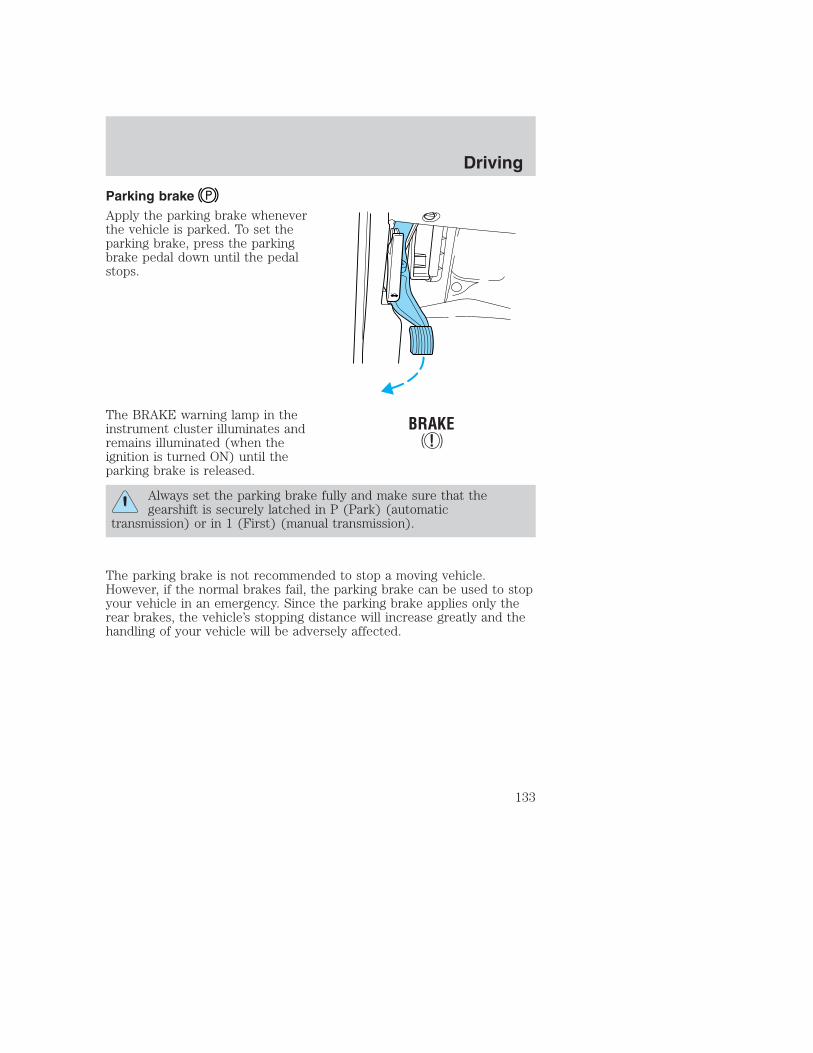
Parking brakeApply the parking brake wheneverthe vehicle is parked. To set theparking brake, press the parkingbrake pedal down until the pedalstops.
The BRAKE warning lamp in theinstrument cluster illuminates andremains illuminated (when theignition is turned ON) until theparking brake is released.
Always set the parking brake fully and make sure that thegearshift is securely latched in P (Park) (automatic
transmission) or in 1 (First) (manual transmission).
The parking brake is not recommended to stop a moving vehicle.However, if the normal brakes fail, the parking brake can be used to stopyour vehicle in an emergency. Since the parking brake applies only therear brakes, the vehicle’s stopping distance will increase greatly and thehandling of your vehicle will be adversely affected.
Driving
133

Pull the release lever to release thebrake. Driving with the parkingbrake on will cause the brakes towear out quickly and reduce fueleconomy.
STEERING YOUR VEHICLEYour vehicle is equipped with power steering. Power steering uses energyfrom the engine to help steer the vehicle.
Never hold the steering wheel to the extreme right or the extreme leftposition for more than a few seconds when the engine is running. Thisaction could damage the power steering pump.
If the amount of effort needed to steer your vehicle changes at aconstant vehicle speed, have the power steering system checked. If thepower steering system breaks down (or if the engine is turned off), youcan steer the vehicle manually, but it takes more effort.
After any severe impact such as striking large potholes, sliding into curbson icy roads or a collision involving the front end, have the frontsuspension and steering checked for possible damage.
TRACTION-LOK AXLE (IF EQUIPPED)This axle provides added traction on slippery surfaces, particularly whenone wheel is on a poor traction surface. Under normal conditions, theTraction-Lok axle functions like a standard rear axle.
Extended use of other than the manufacturer’s specified size tires on aTraction-Lok rear axle could result in a permanent reduction ineffectiveness. This loss of effectiveness does not affect normal drivingand should not be noticeable to the driver.
To avoid injury, never run the engine with one wheel off theground, such as when changing a tire.
PULL
Driving
134
PREPARING TO DRIVE YOUR VEHICLE
Utility vehicles have a significantly higher rollover rate thanother types of vehicles.
In a rollover crash, an unbelted person is significantly more likelyto die than a person wearing a seat belt.
Your vehicle has special design and equipment features to make itcapable of performing in a wide variety of circumstances. These specialdesign features, such as larger tires and increased ground clearance, givethe vehicle a higher center of gravity than a passenger car.
Vehicles with a higher center of gravity such as utility andfour-wheel drive vehicles handle differently than vehicles with a
lower center of gravity. Utility and four-wheel drive vehicles are notdesigned for cornering at speeds as high as passenger cars any morethan low-slung sports cars are designed to perform satisfactorily underoff-road conditions. Avoid sharp turns, excessive speed and abruptmaneuvers in these vehicles. Failure to drive cautiously could result inan increased risk of vehicle rollover, personal injury and death.
Loaded vehicles, with a higher center of gravity, may handledifferently than unloaded vehicles. Extra precautions, such as
slower speeds and increased stopping distance, should be taken whendriving a heavily loaded vehicle.
Your vehicle has the capability to haul more cargo and people than mostpassenger cars. Depending upon the type and placement of the load,hauling people and cargo may raise the center of gravity of the vehicle.
Use extra caution while becoming familiar with your vehicle. Know thecapabilities and limitations of both you as a driver and your vehicle.
Driving
135

AUTOMATIC TRANSMISSION OPERATION (IF EQUIPPED)
Brake-shift interlockThis vehicle is equipped with a brake-shift interlock feature that preventsthe gearshift lever from being moved from P (Park) when the ignition isin the ON position unless brake pedal is depressed.
If you cannot move the gearshift lever out of P (Park) with ignition inthe ON position and the brake pedal depressed:
1. Apply the parking brake, turn ignition to the LOCK position, thenremove the key.
2. Reinsert the key and turn the ignition to the OFF position.
3. Press and hold down the brake pedal and shift into N (Neutral).
4. Start the vehicle.
If it is necessary to use the above procedure to move the gearshift lever,it is possible that a fuse has blown or the vehicle’s brakelamps are notoperating properly. Refer to Fuses and relays in the Roadsideemergencies chapter.
Do not drive your vehicle until you verify that the brakelampsare working.
If your vehicle gets stuck in mud or snow it may be rocked out byshifting from forward and reverse gears, stopping between shifts, in asteady pattern. Press lightly on the accelerator in each gear.
Do not rock the vehicle for more than a few minutes. Thetransmission and tires may be damaged or the engine mayoverheat.
Always set the parking brake fully and make sure the gearshift islatched in P (Park). Turn off the ignition whenever you leave
your vehicle.
If the parking brake is fully released, but the brake warning lampremains illuminated, the brakes may not be working properly.
See your dealer or a qualified service technician.
Driving
136

Driving with a 4–speed automatic transmission
Understanding gearshift positionsTo put your vehicle in gear, start the engine, depress the brake pedal,then move gearshift lever out of P (Park).
Hold the brake pedal down while you move the gearshift leverfrom P (Park) to another position. If you do not hold the brake
pedal down, your vehicle may move unexpectedly and injure someone.
P (Park)Always come to a complete stopbefore shifting into P (Park). Makesure the gearshift lever is securelylatched in P (Park). This positionlocks the transmission and preventsthe rear wheels from turning.
Always set the parking brake fully and make sure the gearshiftlever is latched in P (Park). Turn off the ignition whenever you
leave your vehicle.
R (Reverse)With the gearshift lever in R(Reverse), the vehicle will movebackward. Always come to acomplete stop before shifting intoand out of R (Reverse).
N (Neutral)With the gearshift lever in N(Neutral), the vehicle can be startedand is free to roll. Hold the brakepedal down while in this gear.
Driving
137

(Overdrive)The normal driving position for thebest fuel economy. Transmissionoperates in gears one through four.
(Overdrive) can be deactivatedby pressing the transmission controlswitch (TCS) on the end of thegearshift lever.
The transmission control indicatorlight (TCIL) (the word OFF) on theend of the gearshift lever willilluminate.
Drive – Not shown on the display. Activate by pressing the transmissioncontrol switch (TCS) on the end of the gearshift lever with the gearshiftin the position. The TCIL (the word OFF) will illuminate on thegearshift lever. Transmission operates in gears one through three.(Drive) provides more engine braking than (Overdrive) and is usefulwhen:
• driving with a heavy load.
• towing a trailer up or down steep hills.
• additional engine downhill braking is desired. If towing a trailer, referto Driving while you tow in the Trailer towing section.
To return to (Overdrive) mode, press the transmission control switch(TCS). The TCIL (the word OFF) will no longer be illuminated.
Each time the vehicle is started, the transmission will automaticallyreturn to normal overdrive mode.
Every time the vehicle is shut off and restarted, you must press thetransmission control switch to cancel overdrive operation if driving inoverdrive is not desired.
2 (Second)Use 2 (Second) to start-up onslippery roads or to provideadditional engine braking ondowngrades.
OVERDRIVE OFF
OVERDRIVE
Driving
138

1 (First)Use 1 (Low) to provide maximumengine braking on steepdowngrades. Upshifts can be madeby shifting to 2 (Second) or to(Overdrive). Selecting 1 (Low) athigher speeds causes the transmission to shift to a lower gear, and willshift to 1 (Low) after vehicle decelerates to the proper speed.
Forced DownshiftsTo gain acceleration in (Overdrive) or Drive (O/D OFF) whenpassing another vehicle, push the accelerator to the floor. Thetransmission will downshift to the appropriate gear: third, second or firstgear.
Shift strategy (4R100 automatic transmission)To account for customer driving habits and conditions, your 4R100automatic transmission electronically controls the shift quality by usingan adaptive learning strategy. The adaptive learning strategy ismaintained by power from the battery. When the battery is disconnectedor a new battery is installed, the transmission must relearn its adaptivestrategy. Optimal shifting will resume within a few hundred kilometers(miles) of operation.
If the shift quality does not improve within a few hundredkilometers (miles) of operation, or if the downshifts and otherthrottle conditions do not function normally, see your dealer or aqualified service technician as soon as possible.
MANUAL TRANSMISSION OPERATION (IF EQUIPPED)
Using the clutchVehicles equipped with a manual transmission have a starter interlockthat prevents cranking the engine unless the clutch pedal is fullydepressed.
Driving
139

When starting a vehicle with a manual transmission, you must:
1. Make sure the parking brake isfully set.
2. Depress the clutch pedal fully.
3. Put the gearshift lever in N(Neutral).
4. Turn the ignition to position 5(START) to start the engine, let theengine idle for a few seconds.
5. Depress the brake pedal.
6. Release the parking brake.
7. Move the gearshift lever to thedesired gear.
8. Release the brake pedal.
9. Slowly release the clutch pedalwhile slowly pressing down on theaccelerator pedal.
• Do not drive with your foot resting on the clutch pedal and do not usethe clutch to hold your vehicle at a standstill while waiting on a hill.These actions will greatly reduce clutch life.
1
2 4 R
3 D 1
2 4
R
L
3 D
1
2
34
5
Driving
140
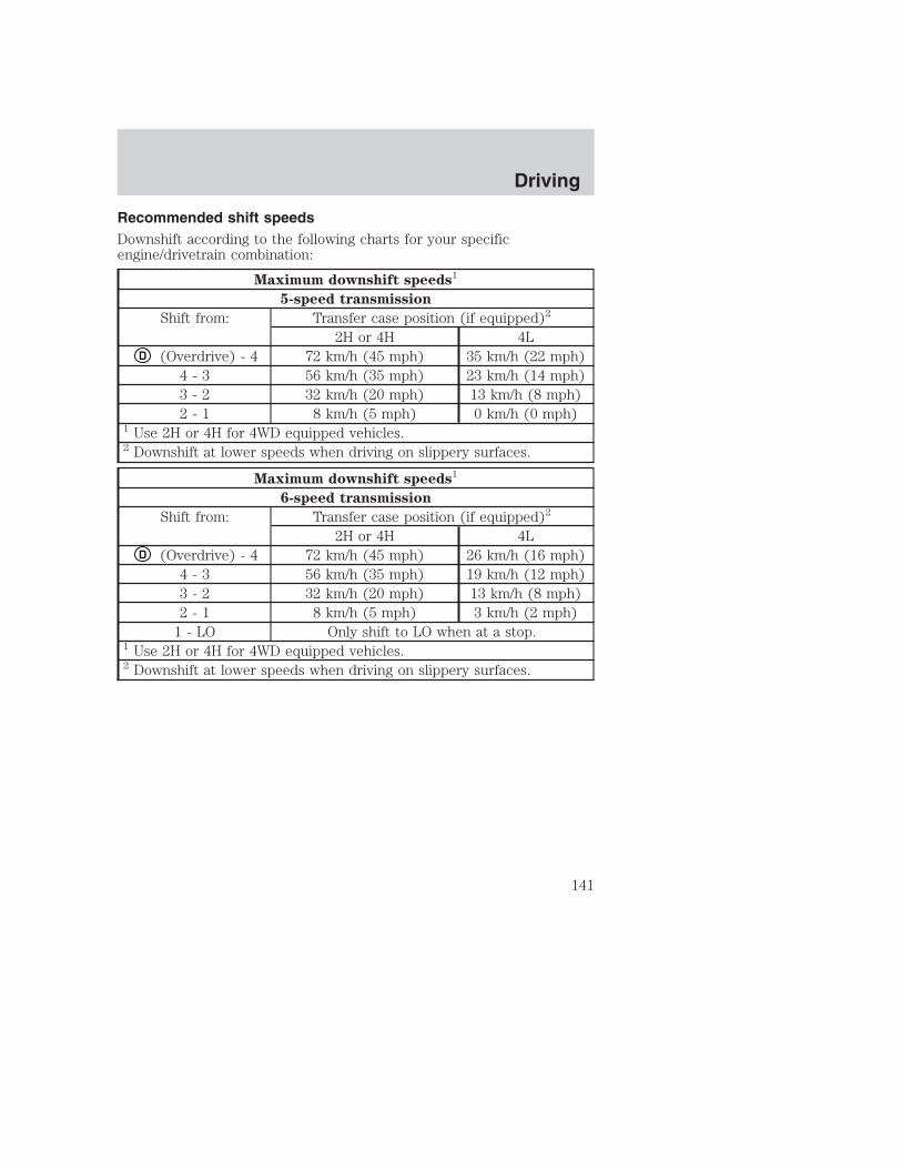
Recommended shift speedsDownshift according to the following charts for your specificengine/drivetrain combination:
Maximum downshift speeds1
5-speed transmission
Shift from: Transfer case position (if equipped)2
2H or 4H 4LD (Overdrive) - 4 72 km/h (45 mph) 35 km/h (22 mph)
4 - 3 56 km/h (35 mph) 23 km/h (14 mph)3 - 2 32 km/h (20 mph) 13 km/h (8 mph)2 - 1 8 km/h (5 mph) 0 km/h (0 mph)
1 Use 2H or 4H for 4WD equipped vehicles.2 Downshift at lower speeds when driving on slippery surfaces.
Maximum downshift speeds1
6-speed transmission
Shift from: Transfer case position (if equipped)2
2H or 4H 4LD (Overdrive) - 4 72 km/h (45 mph) 26 km/h (16 mph)
4 - 3 56 km/h (35 mph) 19 km/h (12 mph)3 - 2 32 km/h (20 mph) 13 km/h (8 mph)2 - 1 8 km/h (5 mph) 3 km/h (2 mph)
1 - LO Only shift to LO when at a stop.1 Use 2H or 4H for 4WD equipped vehicles.2 Downshift at lower speeds when driving on slippery surfaces.
Driving
141

Parking your vehicle1. Disengage the clutch, apply brakeand shift into N (Neutral).
2. Set parking brake.
3. Shift into 1 (First).
4. Turn the ignition key to position3 (OFF).
1
2 4 R
3 D 1
2 4
R
L
3 D
3
2
1
5
4
Driving
142

Do not park your vehicle in Neutral, it may move unexpectedlyand injure someone. Use 1 (First) gear and set the parking brake
fully.
ReverseMake sure that your vehicle is at a complete stop before you shift into R(Reverse). Failure to do so may damage the transmission.
Put the gearshift lever in N (Neutral) and wait at least three secondsbefore shifting into R (Reverse).
With the 5–speed transmission youcan shift into R (Reverse) only bymoving the gearshift lever from leftof 3 (Third) and 4 (Fourth) gearsbefore you shift into R (Reverse).This is a special lockout feature thatprotects you from accidentallyshifting into R (Reverse) when youdownshift from D (Overdrive).
With the 6–speed transmission youcan shift into R (Reverse) bymoving the gearshift to the extremeleft from N (Neutral).
1 3
2 4 R
D
R 1
L
3
42
D
Driving
143

Removing key from ignition• Turn the ignition key to position
2.
• Push the release lever forwardand rotate the key towards youand remove.
POWER TAKE OFF (PTO) CAPABILITY (IF EQUIPPED)Some vehicles equipped with an automatic transmission and the 6.8L or7.3L engine are also equipped with Power Take Off (PTO) capability.These vehicles have a special transmission case, internal components andcalibration for PTO usage.
The PTO can be used during mobile and stationarycontinuous/intermittent applications.
PTO operation is disabled while the vehicle is in Overdrive (the TCIL willnot be illuminated), in N (Neutral), during engine cranking. Transmissionupshift and downshift schedules will be reduced by about 15% and willhave a firmer shift feel during PTO mobile applications.
The PTO cannot be disabled while the transmission is in Manual 3(Overdrive position with Overdrive canceled), Manual 2, Manual 1.
Refer to the Body Builder’s Layout Book for recommended electricalinstallation.
Driving
144

FOUR-WHEEL DRIVE (4WD) OPERATION (IF EQUIPPED)
For important information regarding safe operation of this typeof vehicle, see Preparing to drive your vehicle in this chapter.
When four–wheel drive (4WD) is engaged, power is supplied to all fourwheels through a transfer case. 4WD power can be selected whenadditional driving power is desired.
If equipped with the Electronic Shift 4WD System, and theinstrument panel control is moved to 4WD Low while the vehicleis moving, the system will not engage and no damage will occur tothe 4WD system. Before 4WD Low can be engaged, the vehiclemust be brought to a complete stop with the brake pedaldepressed and the transmission placed in neutral (or the clutchpedal depressed on manual transmissions).
4WD operation is not recommended on dry pavement. Doing so couldresult in difficult disengagement of the transfer case, increased tire wearand decreased fuel economy.
Electronic shift on the fly (ESOF) 4x4 system (if equipped)The 4WD system:
• provides 4x4 High engagement and disengagement while the vehicle ismoving.
• is operated by a rotary control located on the instrument panel thatallows you select 2WD, 4x4 High or 4x4 Low operation.
• uses hub locks that can be engaged and disengaged automatically byusing a rotary control located on the instrument panel.
Driving
145

• automatic hub locks can bemanually overridden by rotatingthe hub lock control from AUTOto LOCK. Automatic operation ofthe hub locks is recommended.
• For proper operation, makesure that the arrow and theindicator dot on the hub arealigned.
Manual 4x4 system (if equipped)The 4WD system is engaged ordisengaged by rotating the controlfor both front wheel hub locks fromthe FREE or LOCK position, thenmanually engaging or disengagingthe transfer case with thefloor-mounted shifter.
• For proper operation, makesure that the arrow and theindicator dot on the hub arealigned.
4WD system indicator lightsThe 4WD system indicator lights illuminate only under the followingconditions. If these lights illuminate when driving in 2WD, contact yourFord dealer as soon as possible.
• 4x4-momentarily illuminates afterthe engine is started. Illuminateswhen 4H (4x4 High) or 4L (4x4Low) is engaged.
4x4
Driving
146
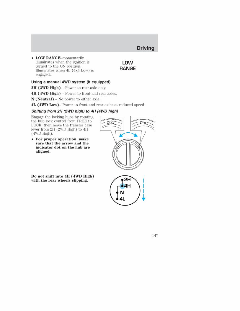
• LOW RANGE–momentarilyilluminates when the ignition isturned to the ON position.Illuminates when 4L (4x4 Low) isengaged.
Using a manual 4WD system (if equipped)2H (2WD High) – Power to rear axle only.
4H (4WD High) – Power to front and rear axles.
N (Neutral) – No power to either axle.
4L (4WD Low)– Power to front and rear axles at reduced speed.
Shifting from 2H (2WD high) to 4H (4WD high)Engage the locking hubs by rotatingthe hub lock control from FREE toLOCK, then move the transfer caselever from 2H (2WD High) to 4H(4WD High).
• For proper operation, makesure that the arrow and theindicator dot on the hub arealigned.
Do not shift into 4H (4WD High)with the rear wheels slipping. 2H
4H
4LN
Driving
147

Shifting from 4H (4WD high) to 2H (2WD high)Move the transfer case lever to 2H(2WD High) at a stop or anyforward speed up to 88 km/h (55mph).
With the vehicle at complete stop,disengage the locking hubs(optional) by rotating the hub lockcontrol from LOCK to FREE.
• For proper operation, make sure that the arrow and theindicator dot on the hub are aligned.
Shifting from 4H (4WD high) to 4L (4WD low)1. Bring the vehicle to a complete stop.
2. Depress the brake.
3. Place the gearshift lever in N (Neutral) (automatic transmission) ordepress the clutch (manual transmission).
4. Move the transfer case shift leverthrough N (Neutral) directly to 4L(4WD Low) and hold the shift leverin 4L (4WD Low) until the transfercase has fully engaged (up to 15seconds).
5. If the transfer case does notengage into 4L (4WD Low), repeatsteps 1 through 4.
Shifting from 4L (4WD low) to 4H (4WD high) or 2H (2WD high)1. Bring the vehicle to a complete stop.
2. Depress the brake.
3. Place the gearshift lever in N (Neutral) (automatic transmission) ordepress the clutch (manual transmission).
2H4H
4LN
2H4H
4LN
Driving
148

4. Move the transfer case shift leverthrough N (Neutral) directly to 4H(4WD High) or 2H (2WD high) andhold the shift lever in position untilthe transfer case has fully engaged(up to 15 seconds).
5. If the transfer case does notengage, repeat steps 1 through 4.
Using the N (Neutral) positionThe transfer case neutral position overrides the transmission andputs the vehicle in neutral regardless of transmission gearshiftlever position. The vehicle can move forward or backwards.
This position should only be usedwhen towing the vehicle.
Do not leave the vehicle unattended with the transfer case in theN (Neutral) position. Always set the parking brake fully and turn
off the ignition when leaving the vehicle.
Using the electronic shift 4WD system (if equipped)
Positions of the electronic shift systemTo prevent damage, the electronic shift 4WD system is designedto allow up to 45 seconds before the shift command is performed.In the event that conflicting shift commands are selected, allowup to 45 seconds for the shift command to be performed prior toreporting any shift concerns to your dealer.
2WD (2WD High) – Power to rear axle only.
4x4 HIGH (4WD High) – Power delivered to front and rear axles forincreased traction.
4x4 LOW (4WD Low) – Power to front and rear axles at low speeds.
2H4H
4LN
2H4H
4LN
Driving
149

Shifting from 2WD (2WD high) to 4x4 HIGH (4WD high)Rotate the 4WD control to the 4x4HIGH position at speeds up to 88km/h (55 mph).
• To prevent damage, theelectronic shift 4WD system isdesigned to engage 4x4 HIGH(4WD high) when the vehicleis moving. If the 4x4 indicatorlight does not illuminate whenshifting a vehicle that isstationary, start the vehiclemoving. Once the vehicle is moving, 4x4 HIGH (4WD high) willengage and the 4x4 indicator will illuminate.
Do not shift into 4x4 HIGH with the rear wheels slipping.
Shifting from 4x4 HIGH (4WD high) to 2WD (2WD high)Rotate the 4WD control to 2WD atany forward speed. Disengagementof the transfer case and front hubsmay be delayed due to torque bindwhich is caused by driving on dryhard surfaces or performing tightturns while using the 4WD system.
• You do not need to operate the vehicle in R (Reverse) to disengageyour front hubs.
Shifting from 4x4 HIGH (4WD high) to 4x4 LOW (4WD low)1. Bring the vehicle to a complete stop.
2. Depress the brake.
3. Place the gearshift in N (Neutral) (automatic transmission) or depressthe clutch (manual transmission).
4X4HIGH2WD
4X4LOW
4X4HIGH2WD
4X4LOW
Driving
150

4. Move the 4WD control to the 4x4LOW position.
5. Hold the shift command until theLOW RANGE indicator lightilluminates.
6. If the LOW RANGE indicator lightdoes not illuminate after 15seconds, start the vehicle moving,then repeat steps 1 through 5before reporting any shift concernsto your dealer.
Shifting from 4x4 LOW (4WD low) to 4x4 HIGH (4WD high) or 2WD(2WD high)1. Bring the vehicle to a complete stop.
2. Depress the brake.
3. Place the gearshift in N (Neutral) (automatic transmission) or depressthe clutch (manual transmission).
4. Move the 4WD control to the 4x4HIGH (4WD high) or 2WD (2WDhigh) position.
5. Hold the shift command until theLOW RANGE indicator light shutsoff.
6. If the LOW RANGE indicator lightdoes not shut off after 15 seconds,start the vehicle moving, thenrepeat steps 1 through 5 beforereporting any shift concerns to your dealer.
Driving off-road with 4WDYour vehicle is specially equipped for driving on sand, snow, mud andrough terrain and has operating characteristics that are somewhatdifferent from conventional vehicles, both on and off the road.
Maintain steering wheel control at all times, especially in rough terrain.Since sudden changes in terrain can result in abrupt steering wheelmotion, make sure you grip the steering wheel from the outside. Do notgrip the spokes.
2WD4X4LOW
4X4HIGH
2WD4X4LOW
4X4HIGH
Driving
151

Drive cautiously to avoid vehicle damage from concealed objects such asrocks and stumps.
You should either know the terrain or examine maps of the area beforedriving. Map out your route before driving in the area. For moreinformation on driving off-road, read the “Four Wheeling” supplement inyour owner’s portfolio.
If your vehicle gets stuckIf the vehicle is stuck it may be rocked out by shifting from forward andreverse gears, stopping between shifts, in a steady pattern. Press lightlyon the accelerator in each gear.
Do not rock the vehicle if the engine is not at normal operatingtemperature or damage to the transmission may occur.
Do not rock the vehicle for more than a few minutes or damageto the transmission and tires may occur or the engine mayoverheat.
Do not spin the wheels at over 56 km/h (35 mph). The tires mayfail and injure a passenger or bystander.
SandWhen driving over sand, try to keep all four wheels on the most solidarea of the trail. Do not reduce the tire pressures but shift to a lowergear and drive steadily through the terrain. Apply the accelerator slowlyand avoid spinning the wheels.
Mud and waterIf you must drive through high water, drive slowly. Traction or brakecapability may be limited.
When driving through water, determine the depth; avoid water higherthan the bottom of the hubs (if possible) and proceed slowly. If theignition system gets wet, the vehicle may stall.
Once through water, always try the brakes. Wet brakes do not stop thevehicle as effectively as dry brakes. Drying can be improved by movingyour vehicle slowly while applying light pressure on the brake pedal.
After driving through mud, clean off residue stuck to rotating driveshaftsand tires. Excess mud stuck on tires and rotating driveshafts causes animbalance that could damage drive components.
Driving
152

If the transmission, transfer case or front axle are submerged in water,their fluids should be checked and changed, if necessary.
Water intrusion into the transmission may damage thetransmission.
If the front or rear axle is submerged in water, the axle lubricant shouldbe replaced.
Driving on hilly or sloping terrainWhen driving on a hill, avoid driving crosswise or turning on steepslopes. You could lose traction and slip sideways. Drive straight up,straight down or avoid the hill completely. Know the conditions on theother side of a hill before driving over the crest.
When climbing a steep hill, start in a lower gear rather than downshiftingto a lower gear from a higher gear once the ascent has started. Thisreduces strain on the engine and the possibility of stalling.
When descending a steep hill, avoid sudden braking. Shift to a lower gearwhen added engine braking is desired.
When speed control is on and you are driving uphill, your vehicle speedmay drop considerably, especially if you are carrying a heavy load.
If vehicle speed drops more than 16 km/h (10 mph), the speed controlwill cancel automatically. Resume speed with accelerator pedal.
If speed control cancels after climbing the hill, reset speed by pressingand holding the SET ACCEL button (to resume speeds over 50 km/h[30 mph]).
Automatic transmissions may shift frequently while driving up steepgrades. Eliminate frequent shifting by shifting out of (Overdrive) intoa lower gear.
Driving on snow and iceA 4WD vehicle has advantages over 2WD vehicles in snow and ice butcan skid like any other vehicle.
Avoid sudden applications of power and quick changes of direction onsnow and ice. Apply the accelerator slowly and steadily when startingfrom a full stop.
If your vehicle is equipped with a Rear Anti-lock Brake System (RABS),you should be careful when braking. Front brake lock-up, on any surface,causes loss of steering control.
Driving
153
If your vehicle is equipped with a Four Wheel Anti-lock Brake System(ABS), apply the brakes as you normally would. In order to allow theABS to operate properly, keep steady pressure on the brake pedal.
When driving on snow or ice with either braking system, allow morestopping distance and drive slower than usual. Consider using one of thelower gears.
VEHICLE LOADINGBefore loading a vehicle, familiarize yourself with the following terms:
• Base Curb Weight: Weight of the vehicle including any standardequipment, fluids, lubricants, etc. It does not include occupants oraftermarket equipment.
• Payload: Combined maximum allowable weight of cargo, occupantsand optional equipment. The payload equals the gross vehicle weightrating minus base curb weight.
• GVW (Gross Vehicle Weight): Base curb weight plus payloadweight. The GVW is not a limit or a specification.
• GVWR (Gross Vehicle Weight Rating): Maximum permissable totalweight of the base vehicle, occupants, optional equipment and cargo.The GVWR is specific to each vehicle and is listed on the SafetyCertification Label on the driver’s door pillar.
• GAWR (Gross Axle Weight Rating): Carrying capacity for each axlesystem. The GAWR is specific to each vehicle and is listed on theSafety Certification Label on the driver’s door pillar.
• GCW (Gross Combined Weight): The combined weight of thetowing vehicle (including occupants and cargo) and the loaded trailer.
• GCWR (Gross Combined Weight Rating): Maximum permissablecombined weight of towing vehicle (including occupants and cargo)and the loaded trailer
• Maximum Trailer Weight Rating: Maximum weight of a trailer thevehicle is permitted to tow. The maximum trailer weight rating isdetermined by subtracting the vehicle curb weight for eachengine/transmission combination, any required option weight for trailertowing and the weight of the driver from the GCWR for the towingvehicle.
Driving
154

• Maximum Trailer Weight: Maximum weight of a trailer the loadedvehicle (including occupants and cargo) is permitted to tow. It isdetermined by subtracting the weight of the loaded trailer towingvehicle from the GCWR for the towing vehicle.
• Trailer Weight Range: Specified weight range that the trailer mustfall within that ranges from zero to the maximum trailer weight rating.
Remember to figure in the tongue load of your loaded trailer whenfiguring the total weight.
Do not exceed the GVWR or the GAWR specified on thecertification label.
Do not use replacement tires with lower load carrying capacities than theoriginals because they may lower the vehicle’s GVWR and GAWRlimitations. Replacement tires with a higher limit than the originals donot increase the GVWR and GAWR limitations.
The Safety Certification Label, found on the driver’s door pillar, listsseveral important vehicle weight rating limitations. Before adding anyadditional equipment, refer to these limitations. If you are adding weightto the front of your vehicle, (potentially including weight added to thecab), the weight added should not exceed the front axle reserve capacity(FARC). Additional frontal weight may be added to the front axle reservecapacity provided you limit your payload in other ways (i.e. restrict thenumber of occupants or amount of cargo carried).
Always ensure that the weight of occupants, cargo and equipment beingcarried is within the weight limitations that have been established foryour vehicle including both gross vehicle weight and front and rear grossaxle weight rating limits. Under no circumstance should these limitationsbe exceeded. Exceeding any vehicle weight rating limitation could resultin serious damage to the vehicle and/or personal injury.
Special loading instructions for owners of pickup trucks andutility-type vehicles
For important information regarding safe operation of this typeof vehicle, see the Preparing to drive your vehicle section
inthe Driving chapter of this owner guide.
Driving
155

Loaded vehicles, with a higher center of gravity, may handledifferently than unloaded vehicles. Extra precautions, such as
slower speeds and increased stopping distance, should be taken whendriving a heavily loaded vehicle.
Your vehicle has the capability to haul more cargo and people than mostpassenger cars. Depending upon the type and placement of the load,hauling cargo and people may raise the center of gravity of the vehicle.
Calculating the load your vehicle can carry/tow1. Use the appropriate maximum gross combined weight rating (GCWR)chart to find the maximum GCWR for your type engine and rear axle ratio.
2. Weigh your vehicle as you customarily operate the vehicle withoutcargo. To obtain correct weights, try taking your vehicle to a shippingcompany or an inspection station for trucks.
3. Subtract your loaded vehicle weight from the maximum GCWR on thefollowing charts. This is the maximum trailer weight your vehicle can towand must fall below the maximum shown under maximum trailer weighton the chart.
DRIVING THROUGH WATERDo not drive quickly through standing water, especially if the depth isunknown. Traction or brake capability may be limited and if the ignitionsystem gets wet, your engine may stall. Water may also enter yourengine’s air intake and severely damage your engine.
If driving through deep or standing water is unavoidable, proceed veryslowly. Never drive through water that is higher than the bottom of thehubs (for trucks) or the bottom of the wheel rims (for cars).
Once through the water, always try the brakes. Wet brakes do not stop thevehicle as effectively as dry brakes. Drying can be improved by movingyour vehicle slowly while applying light pressure on the brake pedal.
Driving through deep water where the transmission vent tube issubmerged may allow water into the transmission and causeinternal transmission damage.
Driving
156

TRAILER TOWINGYour vehicle may tow aConventional/Class IV trailer or fifthwheel trailer provided the maximumtrailer weight is less than or equal tothe maximum trailer weight listedfor your engine and rear axle ratioon the following charts.
2nd unit bodies are not included inmaximum trailer weight ratings.Weight of additional “body” must besubtracted from the maximumtrailer weight.
Your vehicle’s load capacity is designated by weight, not by volume, soyou cannot necessarily use all available space when loading a vehicle.
Towing a trailer places an additional load on your vehicle’s engine,transmission, axle, brakes, tires and suspension. Inspect thesecomponents carefully prior to and after any towing operation.
Do not exceed the GVWR or the GAWR specified on thecertification label.
Towing trailers beyond the maximum recommended gross trailerweight could result in engine damage, transmission/axle damage,
structural damage, loss of control, and personal injury.
F-250 w/manual transmission
Engine Rear axle
ratio
Maximum
GCWR - kg (lbs.)
Maximum trailer
weight - kg (lbs.)1
5.4L 3.73 6 124 (13 500) 4 536 (10 000)5.4L 4.10 6 804 (15 000) 4 536 (10 000)6.8L 3.73 7 484 (16 500) 4 536 (10 000)6.8L 4.30 8 165 (18 000) 4 536 (10 000)
1Conventional/Class IV trailer hitch only. Fifth wheel trailer maximumweights can be calculated by subtracting GVW from GCWR.
Driving
157

F-250 w/automatic transmission
Engine Rear axle
ratio
Maximum
GCWR - kg (lbs.)
Maximum trailer
weight - kg (lbs.)1
5.4L 3.73 6 124 (13 500) 4 536 (10 000)5.4L 4.10 6 804 (15 000) 4 536 (10 000)6.8L 3.73 7 711 (17 000) 4 536 (10 000)6.8L 4.30 8 165 (18 000) 4 536 (10 000)
1Conventional/Class IV trailer hitch only. Fifth wheel trailer maximumweights can be calculated by subtracting GVW from GCWR.
F-350 w/manual transmission
Engine Rear axle
ratio
Maximum
GCWR - kg (lbs.)
Maximum trailer
weight - kg (lbs.)1
5.4L 3.73 6 124 (13 500) 4 536 (10 000)5.4L 4.10 6 804 (15 000) 4 536 (10 000)6.8L 3.73 7 484 (16 500) 4 536 (10 000)6.8L 4.10 8 392 (18 500) 4 536 (10 000)6.8L 4.30 9 072 (20 000) 4 536 (10 000)
1Conventional/Class IV trailer hitch only. Fifth wheel trailer maximumweights can be calculated by subtracting GVW from GCWR.
F-350 w/automatic transmission
Engine Rear axle
ratio
Maximum
GCWR - kg (lbs.)
Maximum trailer
weight - kg (lbs.)1
5.4L 3.73 6 124 (13 500) 4 536 (10 000)5.4L 4.10 6 804 (15 000) 4 536 (10 000)6.8L 3.73 7 711 (17 000) 4 536 (10 000)6.8L 4.30 9 072 (20 000) 4 536 (10 000)
1Conventional/Class IV trailer hitch only. Fifth wheel trailer maximumweights can be calculated by subtracting GVW from GCWR.
Driving
158

F-450 with manual transmission
Engine Rear axle
ratio
Maximum
GCWR - kg (lbs.)
Maximum trailer
weight - kg (lbs.)1
6.8L 4.88 9 979 (22 000) 4 536 (10 000)6.8L 5.38 9 979 (22 000) 4 536 (10 000)
1Conventional/Class IV trailer hitch only. Fifth wheel trailer maximumweights can be calculated by subtracting GVW from GCWR.
F-450 w/automatic transmission
Engine Rear axle
ratio
Maximum
GCWR - kg (lbs.)
Maximum trailer
weight - kg (lbs.)1
6.8L 4.88 10 886 (24 000) 4 536 (10 000)6.8L 5.38 11 794 (26 000) 4 536 (10 000)
1Conventional/Class IV trailer hitch only. Fifth wheel trailer maximumweights can be calculated by subtracting GVW from GCWR.
F-550
Engine Rear axle
ratio
Maximum
GCWR - kg (lbs.)
Maximum trailer
weight - kg
(lbs.)1
6.8L 4.88 10 886 (24 000) 4 536 (10 000)6.8L 5.38 11 794 (26 000) 4 536 (10 000)
1Conventional/Class IV trailer hitch only. Fifth wheel trailer maximumweights can be calculated by subtracting GVW from GCWR.
Towing a Class IV trailer (extra heavy duty) 2 268–4 536 kg(5 001–10 000 lbs.) trailer weight requires a weight-distributingor fifth-wheel hitch. Trailers over 4 536 kg (10 000 lbs.) require afifth-wheel hitch.
Preparing to towUse the proper equipment for towing a trailer, and make sure it isproperly attached to your vehicle. See your dealer or a reliable trailerdealer if you require assistance.
Driving
159

HitchesDo not use hitches that clamp onto the vehicle’s bumper or attach to theaxle. You must distribute the load in your trailer so that 10%–15% of thetotal weight of the trailer is on the tongue.
Load equalizing hitchWhen hooking up a trailer using a load equalizing hitch, always use thefollowing procedure:
1. Park the unloaded vehicle on a level surface. With the ignition on andall doors closed, allow the vehicle to stand for several minutes so that itcan level.
2. Measure the height of a reference point on the front and rear bumpersat the center of the vehicle.
3. Attach the trailer to the vehicle and adjust the hitch equalizers so thatthe front bumper height is within 0–13 mm (0.5 in) of the referencepoint. After proper adjustment, the rear bumper should be no higherthan in Step 2.
Adjusting an equalizing hitch so the rear bumper of the vehicleis higher than it was unloaded will defeat the function of the
load equalizing hitch and may cause unpredictable handling.
Safety chainsAlways connect the trailer’s safety chains to the frame or hook retainersof the vehicle hitch. To connect the trailer’s safety chains, cross thechains under the trailer tongue and allow slack for turning corners.
If you use a rental trailer, follow the instructions that the rental agencygives to you.
Do not attach safety chains to the bumper.
Trailer brakesElectric brakes and manual, automatic or surge-type trailer brakes are safeif installed properly and adjusted to the manufacturer’s specifications. Thetrailer brakes must meet local and Federal regulations.
Driving
160

Do not connect a trailer’s hydraulic brake system directly to yourvehicle’s brake system. Your vehicle may not have enough
braking power and your chances of having a collision greatly increase.
The braking system of the tow vehicle is rated for operation at theGVWR not GCWR.
Trailer lampsTrailer lamps are required on most towed vehicles. Make sure yourtrailer lamps conform to local and Federal regulations. See your dealer ortrailer rental agency for proper instructions and equipment for hookingup trailer lamps.
Using a step bumper (if equipped)The rear bumper is equipped with an integral hitch and only requires aball with a 25.4 mm (one inch) shank diameter. The bumper has a2 270 kg (5 000 lb.) trailer weight and 227 kg (500 lb.) tongue weightcapacity.
If it is necessary to relocate the trailer hitch ball position, aframe-mounted trailer hitch must be installed.
Driving while you towWhen towing a trailer:
• Ensure that you turn off your speed control. The speed control mayshut off automatically when you are towing on long, steep grades.
• Consult your local motor vehicle speed regulations for towing a trailer.
• Use a lower gear when towing up or down steep hills. This willeliminate excessive downshifting and upshifting for optimum fueleconomy and transmission cooling.
• Anticipate stops and brake gradually.
Exceeding the GCWR rating may cause internal transmissiondamage and void your warranty coverage.
Servicing after towingIf you tow a trailer for long distances, your vehicle will require morefrequent service intervals. Refer to your scheduled maintenance guide formore information.
Driving
161

Trailer towing tips• Practice turning, stopping and backing up before starting on a trip to
get the feel of the vehicle trailer combination. When turning, makewider turns so the trailer wheels will clear curbs and other obstacles.
• Allow more distance for stopping with a trailer attached.
• The trailer tongue weight should be no more than 10–15% of theloaded trailer weight.
• After you have traveled 80 km (50 miles), thoroughly check yourhitch, electrical connections and trailer wheel lug nuts.
• When stopped in traffic for long periods of time in hot weather, placethe gearshift in P (Park) (automatic transmissions) or N (Neutral)(manual transmissions). This aids engine cooling and air conditionerefficiency.
• Vehicles with trailers should not be parked on a grade. If you mustpark on a grade, place wheel chocks under the trailer’s wheels.
Launching or retrieving a boatWhen backing down a ramp during boat launching or retrieval,
• Do not allow the static water level to rise above the bottom edge ofthe rear bumper and
• Do not allow waves to break higher than 15 cm (6 inches) above thebottom edge of the rear bumper.
• Disconnect the trailer tow electrical connector to prevent blown fusescaused by water entering into your trailer’s electrical wiring.
Exceeding these limits may allow water to enter critical vehiclecomponents, adversely affecting driveability, emissions and reliability.
Replace front and rear axle lubricants any time the axles have beensubmerged in water. Axle lubricant quantities are not to be checkedunless a leak is suspected.
All Rear Wheel Drive (RWD) vehiclesThis applies to all cars and 4x2 trucks/sport utilities with rear wheeldrive capability.
An example of recreational towing is towing your vehicle behind amotorhome. The following recreational towing guidelines are designed toensure that your transmission is not damaged.
Driving
162

• Place the transmission in N (Neutral).
• Maximum speed is 56 km/h (35 mph).
• Maximum distance is 80 km (50 miles).
If a distance of 80 km (50 miles) or a speed of 56 km/h (35 mph) mustbe exceeded, you must disconnect the driveshaft. Ford recommends thedriveshaft be removed/installed only by a qualified technician. See yourlocal dealer for driveshaft removal/installation.
Improper removal/installation of the driveshaft can causetransmission fluid loss, damage to the driveshaft and internaltransmission components.
RWD vehicles with 4x4 electronic shift transfer case or All WheelDrive (AWD) vehicles with automatic transmissionsRegarding recreational towing or having your vehicle towed, 4x4 vehicleswith electronic shift on the fly and AWD vehicles cannot be towed withany wheels on the ground (with the exception of moving it as a disabledvehicle off the road out of traffic).
SNOWPLOWINGFor low speed snow removal, Ford offers a Snowplow Package as anoption. If you do not have this equipment, do not use your vehicle as asnowplow or powertrain and suspension system damage may occur.
Do not install a snowplow and plow with your vehicle until it has beendriven at least 800 km (500 miles).
Installing the snowplow
Removing the blocker beam without installing snowplowattachment hardware may affect air bag deployment in a crash.
Do not operate the truck unless either the blocker beam or snowplowattachment hardware is installed on the vehicle.
Read the following instructions before installing a snowplow:
• Front GAWR must not exceed 63% of the GVW. Add ballast weight tothe back of the vehicle, if necessary. Refer to the Safety ComplianceCertification Label to find Front GAWR.
Driving
163

• The Front Axle Accessory Reserve Capacity and the Total AccessoryReserve Capacity listed on the bottom right of the Safety ComplianceCertification Label will determine whether or not the addition of asnowplow will overload your vehicle.
• The weight of the snowplow and supporting components distributed tothe front axle must not exceed the front accessory reserve capacity.
• The total weight of the snowplow and aftermarket equipment mustnot exceed the Total Accessory Reserve Capacity.
• The weight of the installed snowplow and aftermarket equipment mustnot load the vehicle beyond the GAWR (front/rear) and GVWR listedon the Safety Compliance Certification Label.
• The total weight of the snowplow and aftermarket equipment must beconsidered part of the payload and must not exceed the GrossCombined Weight Rating (GCWR) for towing.
• Federal and most local regulations require additional exterior lampsfor snowplow-equipped vehicles. Consult your dealer for additionalinformation.
• After installing a snowplow to the vehicle, ensure the vehicle’s fronttoe alignment and front ride height are within specification (reset ifrequired). These specifications are located in the vehicle’s WorkshopManual. Adherence to the toe, tire pressures and ride heightspecification is important for proper tire wear, ride, handling andheadlight aim. Also, maintain the engine oil and transmission fluidchange intervals following the severe duty schedule.
Do not exceed the GVWR or the GAWR specified on thecertification label.
Removing snowplowRead the following instructions before removing a snowplow:
• After removing a snowplow from the vehicle, ensure the vehicle’s fronttoe alignment and front ride height are within specification (reset ifrequired). These specifications are located in the vehicle’s WorkshopManual. Adherence to the toe and ride height specification isimportant for proper tire wear, ride, handling and headlight aim.
Driving
164

Snowplowing with your air bag equipped vehicleYour vehicle is equipped with driverand passenger air bag SupplementalRestraint System (SRS). The SRS isdesigned to activate when thevehicle sustains sufficientlongitudinal deceleration.
Careless or high speed driving while plowing snow which results insufficient vehicle decelerations can deploy the air bag. Such driving alsoincreases the risk of accidents.
All occupants of the vehicle, including the driver, should alwaysproperly wear their safety belts, even when an air bag SRS is
provided.
Never remove or defeat the “tripping mechanisms” designed into thesnow removal equipment by its manufacturer. Doing so may causedamage to the vehicle and the snow removal equipment as well aspossible air bag deployment.
Additional equipment such as snowplow equipment may effectthe performance of the air bag sensors increasing the risk of
injury. Please refer to the Body Builders Layout Book for instructionsabout the appropriate installation of additional equipment.
Do not attempt to service, repair, or modify the Air BagSupplemental Restraint System or its fuses. See your Ford or
Lincoln Mercury dealer.
Driving
165
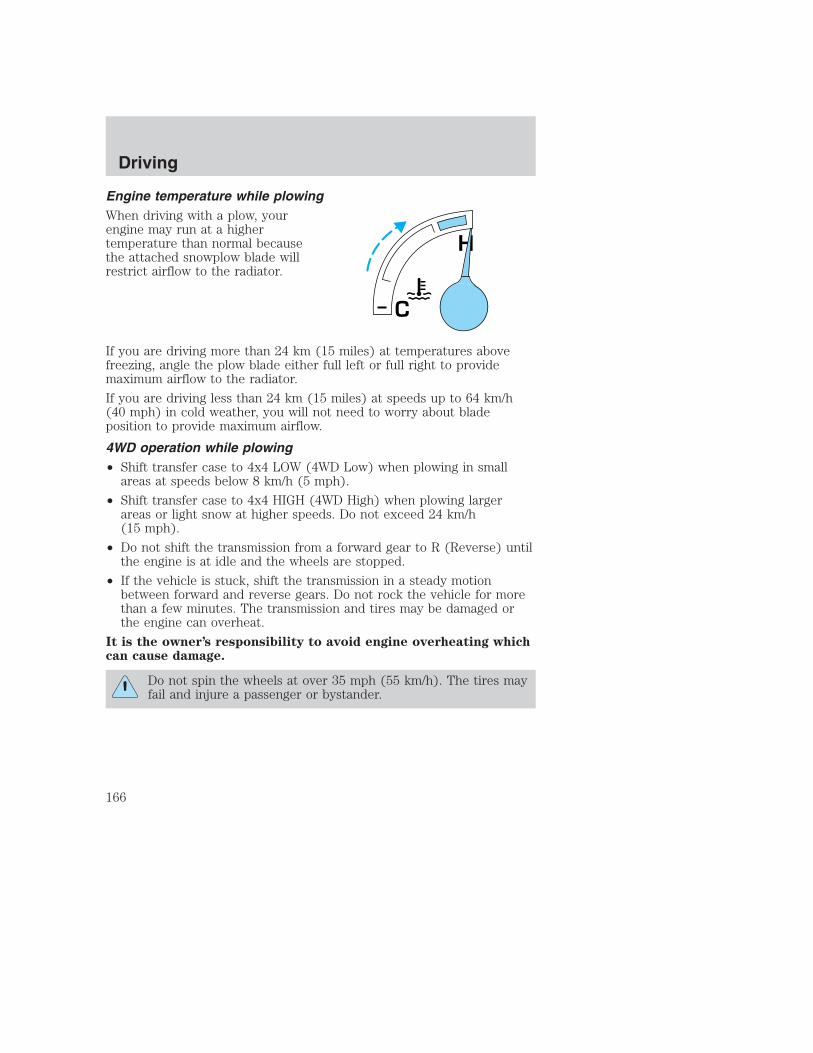
Engine temperature while plowingWhen driving with a plow, yourengine may run at a highertemperature than normal becausethe attached snowplow blade willrestrict airflow to the radiator.
If you are driving more than 24 km (15 miles) at temperatures abovefreezing, angle the plow blade either full left or full right to providemaximum airflow to the radiator.
If you are driving less than 24 km (15 miles) at speeds up to 64 km/h(40 mph) in cold weather, you will not need to worry about bladeposition to provide maximum airflow.
4WD operation while plowing• Shift transfer case to 4x4 LOW (4WD Low) when plowing in small
areas at speeds below 8 km/h (5 mph).
• Shift transfer case to 4x4 HIGH (4WD High) when plowing largerareas or light snow at higher speeds. Do not exceed 24 km/h(15 mph).
• Do not shift the transmission from a forward gear to R (Reverse) untilthe engine is at idle and the wheels are stopped.
• If the vehicle is stuck, shift the transmission in a steady motionbetween forward and reverse gears. Do not rock the vehicle for morethan a few minutes. The transmission and tires may be damaged orthe engine can overheat.
It is the owner’s responsibility to avoid engine overheating whichcan cause damage.
Do not spin the wheels at over 35 mph (55 km/h). The tires mayfail and injure a passenger or bystander.
H
C
Driving
166
GETTING ROADSIDE ASSISTANCETo fully assist you should you have a vehicle concern, Ford offers acomplimentary roadside assistance program. This program is separatefrom the New Vehicle Limited Warranty. The service is available:
• 24–hours, seven days a week
• for the Basic warranty period (Canada) or New Vehicle LimitedWarranty period (U.S.) of three years or 60 000 km (36 000 miles),whichever comes first on Ford and Mercury vehicles, and four years or80 000 km (50 000 miles) on Lincoln vehicles
Roadside assistance will cover:
• changing a flat tire
• jump-starts
• lock-out assistance
• fuel delivery
• towing of your disabled vehicle up to 56.3 kms (35 miles) from thepoint of pickup (this can include to the nearest Ford dealership, oryour selling dealer if within the specified distance.) One tow perdisablement. Even non-warranty related tows, like accidents or gettingstuck in the mud or snow, are covered (some exclusions apply, suchas impound towing or repossession).
Using roadside assistanceComplete the roadside assistance identification card and place it in yourwallet for quick reference. In the United States, this card is found in theOwner Guide portfolio in the glove compartment in Ford vehicles and ismailed to you if you own a Mercury or Lincoln. In Canada, the card isfound in the Roadside Assistance book in the glove compartment.
To receive roadside assistance in the United States for Ford or Mercuryvehicles, call 1–800–241–3673 or if you own a Lincoln vehicle, call1–800–521–4140. In Canada call 1–800–665–2006.
Should you need to arrange roadside assistance for yourself, Ford willreimburse a reasonable amount. To obtain information aboutreimbursement, call 1–800–241–3673 in the United States for Ford orMercury vehicles; or if you own a Lincoln vehicle, call 1–800–521–4140.Call 1–800–665–2006 in Canada.
Roadside emergencies
167

Roadside coverage beyond basic warrantyIn the United States, you may purchase additional roadside assistancecoverage beyond this period through the Ford Auto Club by contactingyour Ford or Lincoln Mercury dealer.
Similarly in Canada, for uninterrupted Roadside Assistance coverage, youmay purchase extended coverage prior to your Basic Warranty’s RoadsideAssistance expiring. For more information and enrollment, contact1–877–294–2582 or visit our website at www.ford.ca.
HAZARD FLASHERUse only in an emergency to warn traffic of vehicle breakdown,approaching danger, etc. The hazard flashers can be operated when theignition is off.
• The hazard lights control islocated on top of the steeringcolumn.
• Depress hazard lights control toactivate all hazard flasherssimultaneously.
• Depress control again to turn theflashers off.
RESETTING THE FUEL PUMP SHUT-OFF SWITCH FUELRESET
The fuel pump shut-off switch is a device intended to stop the electricfuel pump when your vehicle has been involved in a substantial jolt.
After a collision, if the engine cranks but does not start, the fuel pumpshut-off switch may have been activated.
Roadside emergencies
168

The fuel pump shut-off switch islocated in the passenger’s foot well,by the kick panel.
Use the following procedure to reset the fuel pump shut-off switch.
1. Turn the ignition to the OFF position.
2. Check the fuel system for leaks.
3. If no fuel leak is apparent, reset the fuel pump shut-off switch bypushing in on the reset button.
4. Turn the ignition to the ON position. Pause for a few seconds andreturn the key to the OFF position.
5. Make a further check for leaks in the fuel system.
Roadside emergencies
169

FUSES AND RELAYS
FusesIf electrical components in thevehicle are not working, a fuse mayhave blown. Blown fuses areidentified by a broken wire withinthe fuse. Check the appropriatefuses before replacing any electricalcomponents.
NOTE: Always replace a fuse with one that has the specified amperagerating. Using a fuse with a higher amperage rating can cause severe wiredamage and could start a fire.
Standard fuse amperage rating and color
COLOR
Fuse
rating
Mini
fuses
Standard
fuses
Maxi
fuses
Cartridge
maxi
fuses
Fuse link
cartridge
2A Grey Grey — — —3A Violet Violet — — —4A Pink Pink — — —5A Tan Tan — — —
7.5A Brown Brown — — —10A Red Red — — —15A Blue Blue — — —20A Yellow Yellow Yellow Blue Blue25A Natural Natural — — —30A Green Green Green Pink Pink40A — — Orange Green Green50A — — Red Red Red60A — — Blue — Yellow70A — — Tan — Brown80A — — Natural — Black
15
Roadside emergencies
170

Passenger compartment fuse panelThe fuse panel is located below and to the left of the steering wheel bythe brake pedal. Remove the panel cover to access the fuses.
To remove the fuse panel cover,turn the panel fastenerscounterclockwise.
To remove a fuse use the fuse pullertool provided on the fuse panelcover.
Roadside emergencies
171

The fuses are coded as follows.
Fuse/Relay
Location
Fuse Amp
Rating
Passenger Compartment Fuse Panel
Description
1 20A Turn/Hazard Lamps2 — Not Used3 20A Cigar Lighter, Data Link Connector4 10A Glove Box Lamp, Map Lamps, Power
Mirrors, Underhood Lamp5 — Not Used6 — Not Used7 5A Power Window/Lock Switch Illumination8 5A Radio, Headlamp Switch Illumination9 — Not Used
10 15A Dual Fuel Tanks
FU
SE
1R
ELA
Y1
RE
LAY
3
(NO
TU
SE
D)
RE
LAY
4
RE
LAY
5
1222
213
23
314
24
4
161525
526
617
27
718
28
819
29
1121
31
930
1020
Roadside emergencies
172

Fuse/Relay
Location
Fuse Amp
Rating
Passenger Compartment Fuse Panel
Description
11 30A Wiper Motor, Wiper Run/Park Relay Coil,Wiper Hi/LO Relay Coil, Washer PumpRelay Coil
12 15A Horn13 20A Stop Lamps, Center High-mount Stop
Lamp, Trailer Tow Stop Lamp, SpeedControl
14 10A Dome Lamp, Cargo Lamp, CourtesyLamps, Running Board Lamps
15 5A Stop Lamp Switch (Logic): GenericElectronic Module (GEM), PowertrainControl Module (PCM), Four WheelAnti-lock Brake System (4WABS) Module,Brake Shift Interlock, Cluster and PCMKeep Alive Memory
16 15A Instrument Cluster, Hi-beam Headlamps17 — Not Used18 5A Audio19 10A Auxiliary Powertrain Control Module
(APCM) (Diesel only), Instrument Cluster,GEM Module, Overdrive Cancel Switch,Idle Validation Switch (Diesel only),Overhead Console, Diesel PCM via Clutch
20 15A Starter Motor Relay Coil, Clutch Switch21 — Not Used22 10A Passenger Air Bag Activation/Deactivation
Switch, Blower Motor Relay Coil23 10A Air Bag Module24 10A A/C Clutch, Blend Door Actuator, Trailer
Tow Battery Charge Relay Coil, FourWheel Anti-Lock Brake System (4WABS),Turn Signal
25 — Not Used
Roadside emergencies
173

Fuse/Relay
Location
Fuse Amp
Rating
Passenger Compartment Fuse Panel
Description
26 — Not Used27 10A Ignition Run Power Feed (Customer
Access)28 15A Brake Shift Interlock, DRL Relay Coil,
Speed Control Module, Backup Lamps,Trailer Tow Backup Lamp Relay Coil,Electronic Shift On The Fly Hub LockSolenoid, Vacuum Pump Motor
29 5A Instrument Cluster (Charge and AirbagWarning Lamps)
30 30A PCM Relay Coil, Ignition Coil (Gasolineonly), Fuel Heater (Diesel only),Wastegate Solenoid (Diesel only), InjectorDriver Module Relay Coil (Diesel only)
31 5A Fog Lamp SwitchRelay 1 — Interior Lamp RelayRelay 2 — Not UsedRelay 3 — HornRelay 4 — Power Window One Touch Down RelayRelay 5 — Accessory Delay Relay
Roadside emergencies
174

Power distribution boxThe power distribution box, trailertow and electronic shift on the flyrelay blocks are located in theengine compartment near the brakemaster cylinder.
The power distribution box contains high-current fuses that protect yourvehicle’s main electrical systems from overloads.
Always disconnect the battery before servicing high currentfuses.
Always replace the cover to the Power Distribution Box beforereconnecting the battery or refilling fluid reservoirs.
If the battery has been disconnected and reconnected, refer to theBattery section of the Maintenance and care chapter.
Roadside emergencies
175

The high-current fuses and relays are coded as follows.
Fuse/Relay
Location
Fuse Amp
Rating
Power Distribution Box Description
1 7.5A * Trailer Tow Left Stop/Turn Lamp2 10A* Washer Pump3 7.5A* Trailer Tow Right Stop/Turn Lamp4 20A* Trailer Tow Backup Lamps, Trailer Tow
Park Lamps5 20A*
(Gasoline only)5A*
(Diesel only)
Gasoline only-PCM, Fuel Pump RelayCoil, Mass Air Flow Sensor, Fuel InjectorsDiesel only-Dual Alternator �A� Field
6 10A* Gasoline only-A/C (CASS)Diesel only-Single or Dual Alternator �A�Field, Regulator
1929
1828
30 31 32 33 34 35
3736
1727
1626
1525
1424
13
1112
910
78
56
34
12
23 22 21 20
Roadside emergencies
176

Fuse/Relay
Location
Fuse Amp
Rating
Power Distribution Box Description
7 20A*(Gasoline only)
5A*(Diesel only)
Gasoline only-Vapor Management Valve,HEGO Sensors, Intake ManifoldCommunication Control, EVR Solenoid,PCM, Canister Vent SolenoidDiesel only-Dual Alternator �A� Field
8 15A* Trailer Tow Electronic Brake Illumination,Park Lamps, Trailer Tow Park LampRelay Coil
9 10A* Left Headlamp (Low Beam)10 20A* Power Point11 10A* Right Headlamp (Low Beam)12 15A* Daytime Running Lamps (DRL) Resistor,
Fog Lamps13 30A** Multi-function Switch, Headlamps14 60A** Anti-Lock Brake System15 30A** Heated Seats16 30A** Trailer Tow Battery Charge17 30A** Electronic Shift On The Fly Relay,
Transfer Case Shift Motor18 30A** Power Seat, Adjustable Pedals19 20A** Fuel Pump Motor, PCM20 50A** Ignition Switch (B4 & B5)21 50A** Ignition Switch (B1 & B3)22 50A** Junction Box Battery Feed23 40A** Blower Motor24 30A**
(Gasoline only)20A**
(Diesel only)
PCM Power
25 30A*** Power Windows
Roadside emergencies
177

Fuse/Relay
Location
Fuse Amp
Rating
Power Distribution Box Description
26 20A** If equipped with Remote KeylessEntry-Driver Door Unlock Relay Coil, AllDoor Unlock Relay Coil, All Door LockRelay Coil, Park Lamp Flash Relay, If notequipped with Remote KeylessEntry-Power Door Lock Motors
27 - (Gasolineonly)
30A**(Diesel only)
Gasoline only-Not UsedDiesel only-Injector Driver Module
28 30A** Trailer Tow Electronic Brake Controller29 20A** Radio30 -- PCM Power Relay31 -- Blower Motor Relay32 -- A/C CASS (Gasoline only), Injector Driver
Module Power Relay (Diesel only)33 -- Washer Pump Relay34 -- Windshield Wiper Park/Run Relay35 -- Windshield Wiper HI/LO Relay36 -- A/C Clutch Diode37 -- PCM Diode38 -- Trailer Tow Backup Lamp Relay39 -- Trailer Tow Battery Charge Relay40 -- Electronic Shift On The Fly Relay #141 — Electronic Shift On The Fly Relay #2
* Mini Fuses ** Maxi Fuses ***Circuit Breaker
Roadside emergencies
178

CHANGING THE TIRESIf you get a flat tire while driving, do not apply the brake heavily.Instead, gradually decrease your speed. Hold the steering wheel firmlyand slowly move to a safe place on the side of the road.
Spare tire informationYour vehicle may be equipped with a spare tire that can be used aseither a spare or a regular tire. The spare tire is not equipped with wheeltrim. The wheel trim from the original wheel/tire may be used on thespare.
If your vehicle is equipped with 4WD, a spare tire of a differentsize than the road tires should not be used. Such a tire couldresult in damage to driveline components and make the vehicledifficult to control.
Location of the spare tire and toolsThe spare tire and tools for your vehicle are stowed in the followinglocations:
Tool Location
Spare tire(pick-up trucks only)
Under the vehicle, just forward of the rearbumper
Jack Regular cab, crew cab and SuperCabwithout rear bench seat: Fastened to floorpan behind rearmost seat on passenger sideSuperCab with rear bench seat: Under rearbench on passenger side
Jack handle and lugwrench
On top of the radiator support at the frontof the engine compartment
Key, spare tire lock(if equipped)
In the glove box
Removing the spare tire (with spare tire carrier only)1. The following tools are required to remove the spare tire:
• one handle extension and onetypical extension. To assemble,align button with hole and slideparts together. To disconnect,depress button and pull apart.
Roadside emergencies
179

• one wheel nut wrench. Slide oversquare end of jack handle.
2. If equipped, unlock and remove the spare tire lock from the rearbumper drive tube using the the spare tire lock key and the jack handle.
3. Insert the hooked end of the jackhandle into the rear bumper drivetube.
The handle will stop moving andyou will feel forward resistance toturning when properly engaged.
4. Turn the handle counterclockwiseand lower the spare until you canslide the tire rearward and the cableis slack.
5. Remove the retainer through the center of the wheel.
Roadside emergencies
180

Stowing the spare tire1. Lay the tire on the ground with the valve stem facing up.
2. Slide the wheel under the vehicleand install the retainer through thewheel center.
3. Turn the jack handle clockwiseuntil the tire is raised to its originalposition underneath the vehicle. Theeffort to turn the jack handleincreases significantly and the sparetire carrier ratchets when the tire israised to the stowed position. The spare tire carrier has a built-in ratchetfeature that will not allow you to overtighten.
4. Check that the tire lies flat to the frame assembly. Push against thetire to make sure it is tightly seated under the vehicle. Loosen orretighten if necessary.
5. If removed, install the spare tire lock into the bumper drive tube withthe spare tire lock key and jack handle.
Tire change procedure1. Park on a level surface, activatehazard flashers and set the parkingbrake.
• Automatic transmission: Placegearshift lever in P (Park).
• Manual transmission: Placegearshift lever in R (Reverse).
• Electronic Shift On the Fly fourwheel drive: Place transfer casein 2WD, 4x4 HIGH or 4x4 LOW.
• Manual shift transfer case fourwheel drive: Place transfer casein 2H, 4H or 4L.
Roadside emergencies
181

To prevent the vehicle frommoving when you change a
tire, be sure the parking brake isset, then block (in bothdirections) the wheel that isdiagonally opposite (other sideand end of the vehicle) to the tirebeing changed.
2. Turn engine OFF and block the diagonally opposite wheel (block notprovided).
3. Remove the jack, jack handle, lug wrench and spare tire from thestowage locations.
4. Use the tip of the lug wrench to remove any wheel trim.
5. Loosen each wheel lug nutone-half turn counterclockwise butdo not remove them until the wheelis raised off the ground.
When one of the rear wheels is off the ground, the transmissionalone will not prevent the vehicle from moving or slipping off the
jack, even if the transmission is in P (Park) (automatic transmission)or R (Reverse) (manual transmission). To prevent the vehicle frommoving when you change the tire, be sure that the parking brake is setand the diagonally opposite wheel is blocked.
If the vehicle slips off the jack, you or someone else could beseriously injured.
Roadside emergencies
182

The following steps apply to F250/F350 only:
6. Insert the hooked end of the jackhandle into the jack and use thehandle to slide the jack under thevehicle.
7. Position the jack according to thefollowing guides:
• Front (4x2)
Roadside emergencies
183

• Front passenger side (4x4)
• Front driver side (4x4)
Make sure the jack fits into thenotched area next to the differentialhousing.
• Rear
Roadside emergencies
184

Never use the front or reardifferential as a jacking point.
To lessen the risk ofpersonal injury, do not put
any part of your body under thevehicle while changing a tire. Donot start the engine when yourvehicle is on the jack. The jack isonly meant for changing the tire.
8. Turn the jack handle clockwiseuntil the wheel is completely off theground and high enough to installthe spare tire.
9. Remove the lug nuts with the lugwrench.
10. On single rear wheel vehicles,replace the flat tire with the sparetire, making sure the valve stem isfacing outward for all front tires andvehicles equipped with single rearwheels. If replacing an inboard reartire on a dual rear wheel vehicle,the valve stem must be facing outward. If replacing the outboard wheel,the valve stem must be facing inward. Reinstall the lug nuts until thewheel is snug against the hub. Do not fully tighten the lug nuts until thewheel has been lowered.
11. Lower the wheel by turning the jack handle counterclockwise.
Go to step 19.
Roadside emergencies
185

The following steps apply to F350 chassis Cab F450/F550 only:
12. Slide the notched end of thejack handle over the release valveand use the handle to slide the jackunder the vehicle. Make sure thevalve is closed by turning itclockwise.
13. Position the jack according tothe following guides:
• Front (4x2) F350
Roadside emergencies
186

• Front (4x2) F450/550
• Front driver side (4x4)
Roadside emergencies
187

• Front passenger side (4x4)
• Rear
Roadside emergencies
188

14. Insert the jack handle into thepump linkage.
15. Use an up-and-down motionwith the jack handle to raise thewheel completely off the ground.
Hydraulic jacks are equippedwith a pressure release valvethat prevents lifting loads whichexceed the jack’s rated capacity.
16. Remove the lug nuts with thelug wrench.
17. Replace the flat tire with thespare tire, making sure the valve stem is facing outward on all front aninboard rear wheels. If replacing the outboard wheel, the valve stemmust be facing inward. Reinstall the lug nuts until the wheel is snugagainst the hub. Do not fully tighten the lug nuts until the wheel hasbeen lowered.
18. Lower the wheel by slowly turning the release valvecounterclockwise.
Opening the release valve slowly will provide a more controlledrate of descent.
Roadside emergencies
189

The following steps apply to all vehicles:
19. Remove the jack and fully tightenthe lug nuts in the order shown.20. Stow the flat tire. Refer toStowing the spare tire if the vehicleis equipped with a spare tire carrier.21. Stow the jack, jack handle andlug wrench. Make sure the jack issecurely fastened so it does notrattle when driving.22. Unblock the wheels.On vehicles equipped with single rear wheels, retighten the lug nuts tothe specified torque at 800 km (500 miles) after any wheel disturbance(tire rotation, changing a flat tire, wheel removal, etc.).On vehicles equipped with dual rear wheels, retighten the wheel lug nutsto the specified torque at 160 km (100 miles), and again at 800 km (500miles) of new vehicle operation and after any wheel disturbance (tirerotation, changing a flat tire, wheel removal, etc.).
Bolt size Wheel lug nut torque*
Nm Lb-ftM14 x 1.5 200-225 150-165* Torque specifications are for nut and bolt threads free of dirt andrust. Use only Ford recommended replacement fasteners.
On all two-piece flat wheel nuts,apply one drop of motor oil betweenthe flat washer and the nut. Do notapply motor oil to the wheel nutthreads or the wheel stud threads.
When a wheel is installed, always remove any corrosion, dirt orforeign materials present on the mounting surfaces of the wheel or
the surface of the front disc brake hub and rotor that contacts the wheel.Installing wheels without correct metal-to-metal contact at the wheelmounting surfaces can cause the wheel nuts to loosen and the wheel tocome off while the vehicle is in motion, resulting in loss of control.
1
34
2
76
58
Roadside emergencies
190

JUMP STARTING YOUR VEHICLE
The gases around the battery can explode if exposed to flames,sparks, or lit cigarettes. An explosion could result in injury or
vehicle damage.
Batteries contain sulfuric acid which can burn skin, eyes, andclothing, if contacted.
Do not attempt to push-start your vehicle. Automatictransmissions do not have push-start capability; also, thecatalytic conveter may become damaged.
Preparing your vehicleWhen the battery is disconnected or a new battery is installed, thetransmission must relearn its adaptive strategy. As a result of this, thetransmission may shift firmly. This operation is considered normal andwill not affect function or durability of the transmission. Over time, theadaptive learning process will fully update transmission operation to itsoptimum shift feel.
1. Use only a 12–volt supply to start your vehicle.
2. Do not disconnect the battery of the disabled vehicle as this coulddamage the vehicle’s electrical system.
3. Park the booster vehicle close to the hood of the disabled vehiclemaking sure the two vehicles do not touch. Set the parking brake onboth vehicles and stay clear of the engine cooling fan and other movingparts.
4. Check all battery terminals and remove any excessive corrosion beforeyou attach the battery cables. Ensure that vent caps are tight and level.
5. Turn the heater fan on in both vehicles to protect any electricalsurges. Turn all other accessories off.
Roadside emergencies
191

Connecting the jumper cables
1. Connect the positive (+) booster cable to the positive (+) terminal ofthe discharged battery.
Note: In the illustrations, lightning bolts are used to designate theassisting (boosting) battery.
2. Connect the other end of the positive (+) cable to the positive (+)terminal of the assisting battery.
+–
+–
+–+–
Roadside emergencies
192

3. Connect the negative (-) cable to the negative (-) terminal of theassisting battery.
4. Make the final connection of the negative (-) cable to an exposedmetal part of the stalled vehicle’s engine, away from the battery and thecarburetor/fuel injection system. Do not use fuel lines, engine rockercovers or the intake manifold as grounding points.
Do not connect the end of the second cable to the negative (-)terminal of the battery to be jumped. A spark may cause an
explosion of the gases that surround the battery.
5. Ensure that the cables are clear of fan blades, belts, moving parts ofboth engines, or any fuel delivery system parts.
+–
+–
+–
+–
Roadside emergencies
193

Jump starting1. Start the engine of the booster vehicle and run the engine atmoderately increased speed.
2. Start the engine of the disabled vehicle.
3. Once the disabled vehicle has been started, run both engines for anadditional three minutes before disconnecting the jumper cables.
Removing the jumper cables
Remove the jumper cables in the reverse order that they wereconnected.
1. Remove the jumper cable from the ground metal surface.
Note: In the illustrations, lightning bolts are used to designate theassisting (boosting) battery.
2. Remove the jumper cable on the negative (-) connection of thebooster vehicle’s battery.
+–
+–
+–
+–
Roadside emergencies
194

3. Remove the jumper cable from the positive (+) terminal of the boostervehicle’s battery.
4. Remove the jumper cable from the positive (+) terminal of thedisabled vehicle’s battery.
After the disabled vehicle has been started and the jumper cablesremoved, allow it to idle for several minutes so the engine computer canrelearn its idle conditions.
When the battery is disconnected or a new battery is installed, thetransmission must relearn its adaptive strategy. As a result of this, thetransmission may shift firmly. This operation is considered normal andwill not effect function or durability of the transmission. Over time, theadaptive learning process will fully update transmission operation to itsoptimum shift feel.
+–
+–
+–
+–
Roadside emergencies
195
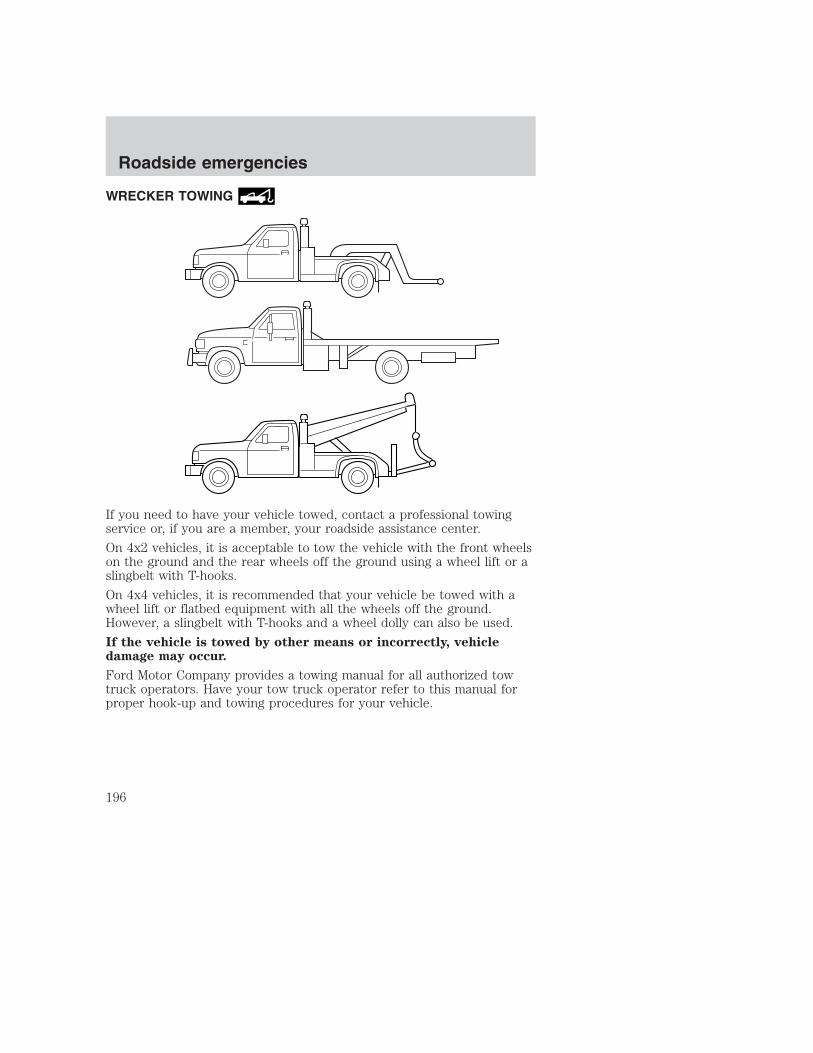
WRECKER TOWING
If you need to have your vehicle towed, contact a professional towingservice or, if you are a member, your roadside assistance center.
On 4x2 vehicles, it is acceptable to tow the vehicle with the front wheelson the ground and the rear wheels off the ground using a wheel lift or aslingbelt with T-hooks.
On 4x4 vehicles, it is recommended that your vehicle be towed with awheel lift or flatbed equipment with all the wheels off the ground.However, a slingbelt with T-hooks and a wheel dolly can also be used.
If the vehicle is towed by other means or incorrectly, vehicledamage may occur.
Ford Motor Company provides a towing manual for all authorized towtruck operators. Have your tow truck operator refer to this manual forproper hook-up and towing procedures for your vehicle.
Roadside emergencies
196

SERVICE RECOMMENDATIONSTo help you service your vehicle:
• We highlight do-it-yourself items in the engine compartment for easylocation.
• We provide a scheduled maintenance guide which makes trackingroutine service easy.
If your vehicle requires professional service, your dealership can providethe necessary parts and service. Check your Warranty Guide to find outwhich parts and services are covered.
Use only recommended fuels, lubricants, fluids and service partsconforming to specifications. Motorcraft parts are designed and built toprovide the best performance in your vehicle.
PRECAUTIONS WHEN SERVICING YOUR VEHICLEBe especially careful when inspecting or servicing your vehicle.
• Do not work on a hot engine.
• When the engine is running, keep loose clothing, jewelry or long hairaway from moving parts.
• Do not work on a vehicle with the engine running in an enclosedspace, unless you are sure you have enough ventilation.
• Keep all lit cigarettes, open flames and other lit material away fromthe battery and all fuel related parts.
If you disconnect the battery, the engine must “relearn” its idleconditions before your vehicle will drive properly, as explained in theBattery section in this chapter.
Maintenance and care
197

Working with the engine off• Automatic transmission:
1. Set the parking brake and ensure the gearshift is securely latched in P(Park).
2. Turn off the engine and remove the key.
3. Block the wheels to prevent the vehicle from moving unexpectedly.
• Manual transmission:
1. Set the parking brake.
2. Depress the clutch and place the gearshift in 1 (First).
3. Turn off the engine and remove the key.
4. Block the wheels to prevent the vehicle from moving unexpectedly.
Working with the engine on• Automatic transmission:
1. Set the parking brake and ensure the gearshift is securely latched in P(Park).
2. Block the wheels to prevent the vehicle from moving unexpectedly.
NOTE:Do not start your engine with the air cleaner removed and do notremove it while the engine is running.
• Manual transmission:
1. Set the parking brake, depress the clutch and place the gearshift inneutral.
2. Block the wheels to prevent the vehicle from moving unexpectedly.
NOTE:Do not start your engine with the air cleaner removed and do notremove it while the engine is running.
The cooling fan is automatic and may come on at any time.Always disconnect the negative terminal of the battery before
working near the fan.
Maintenance and care
198
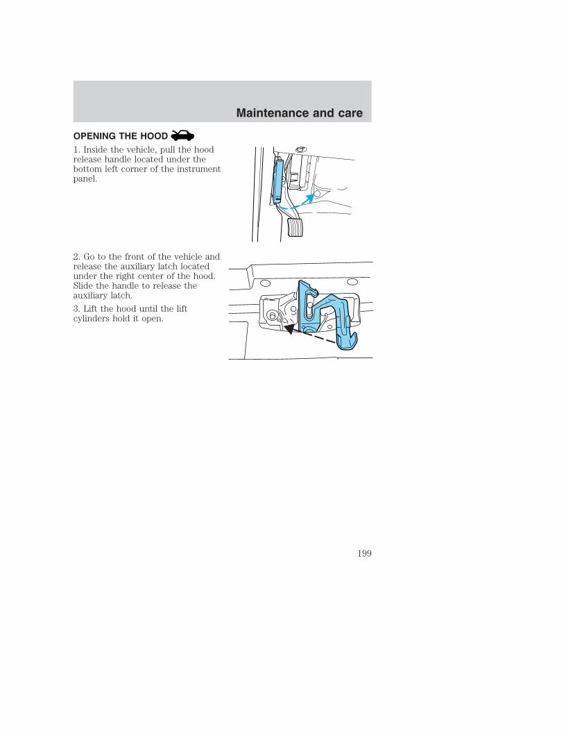
OPENING THE HOOD1. Inside the vehicle, pull the hoodrelease handle located under thebottom left corner of the instrumentpanel.
2. Go to the front of the vehicle andrelease the auxiliary latch locatedunder the right center of the hood.Slide the handle to release theauxiliary latch.
3. Lift the hood until the liftcylinders hold it open.
HOOD
Maintenance and care
199

IDENTIFYING COMPONENTS IN THE ENGINE COMPARTMENT
5.4L V8/6.8L V10 gasoline enginesRefer to the 7.3 Liter Power Stroke Direct Injection Turbo DieselOwner’s Guide Supplement for diesel engine component locations.
1. Engine oil dipstick
2. Clutch fluid reservoir (manual transmission)
3. Brake fluid reservoir
4. Power distribution box
5. Power steering fluid reservoir
6. Air filter assembly
7. Engine coolant reservoir
8. Windshield washer fluid reservoir
9. Battery
10. Engine oil filler cap
11. Transmission fluid dipstick (automatic transmission)
9 10 11 1 2 3 4
8 67
5
Maintenance and care
200

ENGINE OIL
Checking the engine oilRefer to the scheduled maintenance guide for the appropriate intervalsfor checking the engine oil.
1. Make sure the vehicle is on level ground.
2. Turn the engine off and wait a few minutes for the oil to drain into theoil pan.
3. Set the parking brake and ensure the gearshift is securely latched in P(Park) (automatic transmission) or 1 (First) (manual transmission).
4. Open the hood. Protect yourself from engine heat.
5. Locate and carefully remove theengine oil level indicator (dipstick).
6. Wipe the indicator clean. Insert the indicator fully, then remove itagain.
• If the oil level is between the MIN and MAX marks, the oil level isacceptable. DO NOT ADD OIL.
MIN MAX
Maintenance and care
201
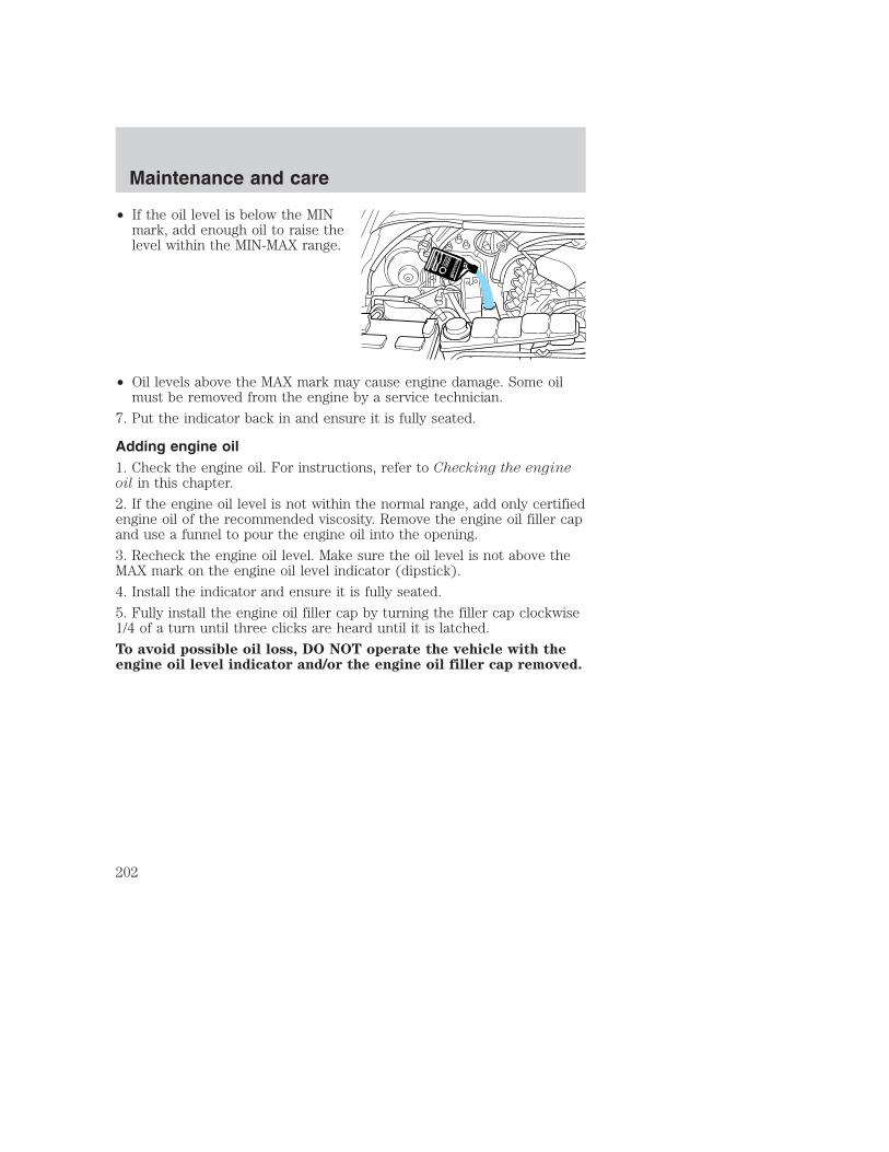
• If the oil level is below the MINmark, add enough oil to raise thelevel within the MIN-MAX range.
• Oil levels above the MAX mark may cause engine damage. Some oilmust be removed from the engine by a service technician.
7. Put the indicator back in and ensure it is fully seated.
Adding engine oil1. Check the engine oil. For instructions, refer to Checking the engineoil in this chapter.
2. If the engine oil level is not within the normal range, add only certifiedengine oil of the recommended viscosity. Remove the engine oil filler capand use a funnel to pour the engine oil into the opening.
3. Recheck the engine oil level. Make sure the oil level is not above theMAX mark on the engine oil level indicator (dipstick).
4. Install the indicator and ensure it is fully seated.
5. Fully install the engine oil filler cap by turning the filler cap clockwise1/4 of a turn until three clicks are heard until it is latched.
To avoid possible oil loss, DO NOT operate the vehicle with theengine oil level indicator and/or the engine oil filler cap removed.
Maintenance and care
202

Engine oil and filter recommendationsLook for this certificationtrademark.
SAE 5W-20 engine oil is recommended.Only use oils “Certified For Gasoline Engines” by the AmericanPetroleum Institute (API). Use Motorcraft or an equivalent oil meetingFord specification WSS-M2C153–H. SAE 5W-20 oil provides optimumfuel economy and durability performance meeting allrequirements for your vehicle’s engine.
Do not use supplemental engine oil additives, oil treatments or enginetreatments. They are unnecessary and could, under certain conditions,lead to engine damage which is not covered by your warranty.
Change your engine oil and filter according to the appropriate schedulelisted in the scheduled maintenance guide.
Ford production and aftermarket (Motorcraft) oil filters are designed foradded engine protection and long life. If a replacement oil filter is usedthat does not meet Ford material and design specifications, start-upengine noises or knock may be experienced.
It is recommended you use the appropriate Motorcraft oil filter (oranother brand meeting Ford specifications) for your engine application.
Maintenance and care
203

BRAKE FLUID
Checking and adding brake fluidBrake fluid should be checked andrefilled as needed. Refer to thescheduled maintenance guide forthe service interval schedules.
1. Clean the reservoir cap beforeremoval to prevent dirt or waterfrom entering the reservoir.
2. Visually inspect the fluid level.
3. If necessary, add brake fluid froma clean un-opened container untilthe level reaches MAX. Do not fillabove this line.
4. Use only a DOT 3 brake fluidcertified to meet Ford specification ESA-M6C25–A. Refer to Lubricantspecifications in the Capacities and specifications chapter.
Brake fluid is toxic. If brake fluid contacts the eyes, flush eyeswith running water for 15 minutes. Seek medical attention if
irritation persists. If taken internally, drink water and induce vomiting.Seek medical attention immediately.
If you use a brake fluid that is not DOT 3, you will causepermanent damage to your brakes.
Do not let the reservoir for the master cylinder run dry. Thismay cause the brakes to fail.
MAX
Maintenance and care
204

CLUTCH FLUID (IF EQUIPPED)Check the clutch fluid level. Refer to the scheduled maintenance guidefor the service interval schedules.
Use only a DOT 3 brake fluid designed to meet Ford specificationESA-M6C25–A. Refer to Capacities and specifications.
Brake fluid is toxic. If brake fluid contacts the eyes, flush eyeswith running water for 15 minutes. Seek medical if irritation
persists. If taken internally, drink water and induce vomiting. Seekmedical attention immediately.
For vehicles equipped with the 6–speed manual transmission,during normal operation, the fluid level in the clutch reservoir shouldremain constant or rise slightly. If the fluid level drops, refill the fluidlevel to the step in the reservoir.
For vehicles equipped with the 5–speed manual transmission,during normal operation, the fluid level in the clutch reservoir will dropslightly. As this occurs, refill the fluid level to the step in the reservoir.
1. Clean the reservoir cap beforeremoval to prevent dirt and waterfrom entering the reservoir.
2. Remove cap and rubberdiaphragm from reservoir.
3. Add fluid until the level reachesthe step in the reservoir.
4. Reinstall rubber diaphragm andcap onto reservoir.
Maintenance and care
205

WINDSHIELD WASHER FLUID
Washer fluidCheck the washer fluid wheneveryou stop for fuel. The reservoir ishighlighted with a symbol.
If the level is low, add enough fluidto fill the reservoir. In very coldweather, do not fill the reservoir allthe way.
Only use a washer fluid that meets Ford specification . Refer toLubricant specifications in the Capacities and specifications chapter.
State or local regulations on volatile organic compounds may restrict theuse of methanol, a common windshield washer antifreeze additive.Washer fluids containing non-methanol antifreeze agents should be usedonly if they provide cold weather protection without damaging thevehicle’s paint finish, wiper blades or washer system.
Do not put washer fluid in the engine coolant reservoir. Washerfluid placed in the cooling system may harm engine and coolingsystem components.
ENGINE COOLANT
Checking engine coolantThe concentration and level of engine coolant should be checked at themileage intervals listed in the scheduled maintenance guide. The coolantconcentration should be maintained at 50/50 coolant and water, whichequates to a freeze point of -36° C (-34° F). Coolant concentrationtesting is possible with a hydrometer or antifreeze tester (such as theRotunda Battery and Antifreeze Tester, 014–R1060). The level of coolantshould be maintained at the “cold full” of “cold fill range” level in thecoolant reservoir. If the level falls below, add coolant per the instructionsin the Adding Engine Coolant section.
Maintenance and care
206

Your vehicle was factory-filled with a 50/50 engine coolant and waterconcentration. If the concentration of coolant falls below 40% or above60%, the engine parts could become damaged or not work properly. A50–50 mixture of coolant and water provides the following:
• Freeze protection down to -36° C (-34° F).
• Boiling protection up to 129° C (265° F).
• Protection against rust and other forms of corrosion.
• Enables calibrated gauges to work properly.
When the engine is cold, check thelevel of the engine coolant in thereservoir.
• The engine coolant should be at the “cold fill level” or within the “coldfill range” as listed on the engine coolant reservoir (depending uponapplication).
• Refer to the Scheduled Maintenance Guide for service intervalschedules.
• Be sure to read and understand Precautions when servicing yourvehicle in this chapter.
If the engine coolant has not been checked at the recommended interval,the engine coolant reservoir may become low or empty. If the reservoir islow or empty, add engine coolant to the reservoir. Refer to Addingengine coolant in this chapter.
NOTE:Automotive fluids are not interchangeable; do not use enginecoolant, antifreeze or windshield washer fluid outside of its specifiedfunction and vehicle location.
COLD FILLRANGE
MAX
MIN
Maintenance and care
207

Adding engine coolantWhen adding coolant, make sure it is a 50/50 mixture of engine coolantand distilled water. Add the mixture to the coolant reservoir, when theengine is cool, until the appropriate fill level is obtained.
Do not add engine coolant when the engine is hot. Steam andscalding liquids released from a hot cooling system can burn you
badly. Also, you can be burned if you spill coolant on hot engine parts.
Do not put engine coolant in the windshield washer fluidcontainer. If sprayed on the windshield, engine coolant could
make it difficult to see through the windshield.
The cooling system in your vehicle is filled with either green-coloredMotorcraft Premium Engine Coolant meeting Ford specificationESE-M97B44–A or yellow-colored Motorcraft Premium Gold EngineCoolant meeting Ford Specification WSS-M97B51–A1. To determine yourvehicle’s coolant type (color), check your coolant reservoir.
• Add Motorcraft Premium Engine Coolant (green-colored),VC-4–A (U.S.) or CXC-10 (Canada) or Motorcraft PremiumGold Engine Coolant (yellow-colored), VC-7–A, depending onthe type of coolant originally equipped in your vehicle. If youare unsure which type of coolant your vehicle requires, check yourcoolant reservoir or contact your local dealer.
• Do not add/mix an orange-colored, extended life coolant suchas Motorcraft Speciality Orange Engine Coolant, VC-2 (US) orCXC-209 (Canada), meeting Ford specification WSS-M97B44–Dwith the factory-filled coolant. Mixing Motorcraft Speciality OrangeEngine Coolant or any orange-colored extended life product with yourfactory filled coolant can result in degraded corrosion protection.
• A large amount of water without engine coolant may be added, in caseof emergency, to reach a vehicle service location. In this instance, thecooling system must be drained and refilled with a 50/50 mixture ofengine coolant and distilled water as soon as possible. Water alone(without engine coolant) can cause engine damage from corrosion,overheating or freezing.
Maintenance and care
208

• Do not use alcohol, methanol or brine or any engine coolantsmixed with alcohol or methanol antifreeze (coolant). Alcoholand other liquids can cause engine damage from overheating orfreezing.
• Do not add extra inhibitors or additives to the coolant. Thesecan be harmful and compromise the corrosion protection of the enginecoolant.
• Do not mix with recycled coolant unless from a Ford-approvedrecycling process (see Use of Recycled Engine Coolant section).
For vehicles with overflow coolant systems with a non-pressurized capon the coolant recovery system, add coolant to the coolant recoveryreservoir when the engine is cool. Add the proper mixture of coolant andwater to the “cold full” level. For all other vehicles, which have a coolantdegas system with a pressurized cap, or if it is necessary to remove thecoolant pressure relief cap on the radiator of a vehicle with an overflowsystem, follow these steps to add engine coolant.
To avoid personal injury, make sure the engine is cool beforeunscrewing the coolant pressure relief cap. The cooling system is
under pressure; steam and hot liquid can come out forcefully when thecap is loosened slightly.
1. Before you begin, turn the engine off and let it cool.
2. When the engine is cool, wrap a thick cloth around the coolantpressure relief cap on the coolant reservoir (an opaque plastic bottle).Slowly turn cap counterclockwise (left) until pressure begins to release.
3. Step back while the pressure releases.
4. When you are sure that all the pressure has been released, use thecloth to turn it counterclockwise and remove the cap.
5. Fill the coolant reservoir slowly with the proper coolant mixture (seeabove), to within the “cold fill range” or the “cold full” level on thereservoir. If you removed the radiator cap in an overflow system, fill theradiator until the coolant is visible and radiator is almost full.
6. Replace the cap. Turn until tightly installed. (Cap must be tightlyinstalled to prevent coolant loss.)
Maintenance and care
209

After any coolant has been added, check the coolant concentration seeChecking Engine Coolant section). If the concentration is not 50/50(protection to –34°F/–36°C), drain some coolant and adjust theconcentration. It may take several drains and additions to obtain a 50/50coolant concentration.
Whenever coolant has been added, the coolant level in the coolantreservoir should be checked the next few times you drive the vehicle. Ifnecessary, add enough 50/50 concentration of engine coolant anddistilled water to bring the liquid level to the proper level.
If you have to add more than 1.0 liter (1.0 quart) of engine coolant permonth, have your dealer check the engine cooling system. Your coolingsystem may have a leak. Operating an engine with a low level of coolantcan result in engine overheating and possible engine damage.
Recycled engine coolantFord Motor Company recommends the use of a recycled engine coolantproduced by Ford-approved processes in vehicles originally equippedwith Motorcraft Premium Engine Coolant (green-colored). However, notall coolant recycling processes produce coolant that meets Fordspecification ESE-M97B44–A. Use of such coolant may harm the engineand cooling system components.
Ford Motor Company does NOT recommend the use of recycled enginecoolant in vehicles originally equipped with Motorcraft Premium GoldEngine Coolant since a Ford-approved recycling process is not yetavailable.
Used engine coolant should be disposed of in an appropriatemanner. Follow your community’s regulations and standards for recyclingand disposing of automotive fluids.
Coolant refill capacityTo find out how much fluid your vehicle’s cooling system can hold, referto Refill capacities in the Capacities and specifications chapter.
Fill your engine coolant reservoir as outlined in Adding engine coolantin this chapter.
Severe climatesIf you drive in extremely cold climates (less than –36° C [–34° F]), itmay be necessary to increase the coolant concentration above 50%.
Maintenance and care
210

Refer to the chart on the coolant container to ensure the coolantconcentration in your vehicle will provide adequate freeze protection.Never increase the engine coolant concentration above 60%(protection to –60°F). At a level over 60%, your engine could overheatand become damaged.
If you drive in extremely hot climates, it is still necessary to maintain thecoolant concentration at 50/50 coolant and water. Do not allow thecoolant concentration to fall below 40% coolant. At a concentrationless than 40%, the corrosion protection to your engine and coolingcomponents may be compromised and permanent damage may result.
What you should know about fail-safe cooling (if equipped)If the engine coolant supply is depleted, this feature allows the vehicle tobe driven temporarily before incremental component damage is incurred.The “fail-safe” distance depends on ambient temperatures, vehicle loadand terrain.
How fail-safe cooling worksIf the engine begins to overheat:
• The engine coolant temperaturegauge will move to the red (hot)area.
• The and symbol willilluminate.
• The Service Engine Soonindicator light will illuminate.
If the engine reaches a preset over-temperature condition, the enginewill automatically switch to alternating cylinder operation. Each disabledcylinder acts as an air pump and cools the engine.
When this occurs the vehicle will still operate. However:
• The engine power will be limited.
• The air conditioning system will be disabled.
Continued operation will increase the engine temperature and the enginewill completely shut down, causing steering and braking effort toincrease.
Once the engine temperature cools, the engine can be re-started. Takeyour vehicle to a service facility as soon as possible to minimize enginedamage.
H
C
Maintenance and care
211

When fail-safe mode is activatedYou have limited engine power when in the fail-safe mode, so drive thevehicle with caution. The vehicle will not be able to maintain high-speedoperation and the engine will run rough. Remember that the engine iscapable of completely shutting down automatically to prevent enginedamage, therefore:
1. Pull off the road as soon as safely possible and turn off the engine.
2. Arrange for the vehicle to be taken to a service facility.
3. If this is not possible, wait a short period for the engine to cool.
4. Check the coolant level and replenish if low.
Never remove the coolant reservoir cap while the engine isrunning or hot.
5. Re-start the engine and take your vehicle to a service facility.
Driving the vehicle without repairing the engine problemincreases the chance of engine damage. Take your vehicle to aservice facility as soon as possible.
Maintenance and care
212

CHECKING AND ADDING POWER STEERING FLUIDCheck the power steering fluid.Refer to the scheduled maintenanceguide for the service intervalschedules. If adding fluid isnecessary, use only MERCON� ATF.
Check the fluid level when it is at ambient temperature, 20° – 80° F(-7° – 25° C):
1. Check the fluid level on the dipstick. It should be between the arrowsin the FULL COLD range. Do not add fluid if the level is within thisrange.
2. If the fluid level is low, start the engine.
3. While the engine idles, turn the steering wheel left and right severaltimes.
4. Turn the engine off.
5. Recheck the fluid level on the dipstick. Do not add fluid if the level isbetween the arrows in the FULL COLD range.
6. If the fluid is low, add fluid in small amounts, continuously checkingthe level until it reaches the FULL COLD range. Be sure to put thedipstick back in the reservoir.
FU
LL C
OLD
Maintenance and care
213

TRANSMISSION FLUID
Checking automatic transmission fluid (if equipped)Refer to your scheduled maintenance guide for scheduled intervals forfluid checks and changes. Your transmission does not consume fluid.However, the fluid level should be checked if the transmission is notworking properly, i.e., if the transmission slips or shifts slowly or if younotice some sign of fluid leakage.
Automatic transmission fluid expands when warmed. To obtain anaccurate fluid check, drive the vehicle until it is at normal operatingtemperature (approximately 30 km [20 miles]). If your vehicle has beenoperated for an extended period at high speeds, in city traffic during hotweather or pulling a trailer, the vehicle should be turned off for about 30minutes to allow fluid to cool before checking.
1. Drive the vehicle 30 km (20 miles) or until it reaches normal operatingtemperature.
2. Park the vehicle on a level surface and engage the parking brake.
3. With the parking brake engaged and your foot on the brake pedal,start the engine and move the gearshift lever through all of the gearranges. Allow sufficient time for each gear to engage.
4. Latch the gearshift lever in P (Park) and leave the engine running.
5. Remove the dipstick, wiping it clean with a clean, dry lint free rag. Ifnecessary, refer to Identifying components in the engine compartmentin this chapter for the location of the dipstick.
6. Install the dipstick making sure it is fully seated in the filler tube.
7. Remove the dipstick and inspect the fluid level. The fluid should be inthe designated area for normal operating temperature or ambienttemperature.
Low fluid levelDo not drive the vehicle if the fluidlevel is at the bottom of the dipstickand the ambient temperature isabove 10°C (50°F).
ADD COLD HOT DO NOT ADD
DON'T ADD IF IN CROSSHATCHED AREA • CHECK WHEN HOT IDLING IN PARK
Maintenance and care
214

Correct fluid levelThe transmission fluid should be checked at normal operatingtemperature 66°C-77°C (150°F-170°F) on a level surface. The normaloperating temperature can be reached after approximately 30 km(20 miles) of driving.
You can check the fluid without driving if the ambient temperature isabove 10°C (50°F). However, if fluid is added at this time, an overfillcondition could result when the vehicle reaches normal operatingtemperature.
The transmission fluid should be inthis range if at normal operatingtemperature (66°C-77°C[150°F-170°F]).
The transmission fluid should be inthis range if at ambient temperature(10°C-35°C [50°F-95°F]).
High fluid levelFluid levels above the safe rangemay result in transmission failure.An overfill condition of transmissionfluid may cause shift and/orengagement concerns and/orpossible damage.
High fluid levels can be caused byan overheating condition.
Adjusting automatictransmission fluid levelsBefore adding any fluid, make sure the correct type is used. The type offluid used is normally indicated on the dipstick and also in theLubricant specifications section in the Capacities and specificationschapter.
Use of a non-approved automatic transmission fluid may causeinternal transmission component damage.
If necessary, add fluid in 250 ml (1/2 pint) increments through the fillertube until the level is correct.
ADD COLD HOT DO NOT ADD
DON'T ADD IF IN CROSSHATCHED AREA • CHECK WHEN HOT IDLING IN PARK
ADD COLD HOT DO NOT ADD
DON'T ADD IF IN CROSSHATCHED AREA • CHECK WHEN HOT IDLING IN PARK
ADD COLD HOT DO NOT ADD
DON'T ADD IF IN CROSSHATCHED AREA • CHECK WHEN HOT IDLING IN PARK
Maintenance and care
215

If an overfill occurs, excess fluidshould be removed by a qualifiedtechnician.
An overfill condition oftransmission fluid may causeshift and/or engagementconcerns and/or possibledamage.
Checking and adding manual transmission fluid (if equipped)1. Clean the filler plug.
2. Remove the filler plug andinspect the fluid level.
3. Fluid level should be at bottom ofthe opening.
4. Add enough fluid through thefiller opening so that the fluid levelis at the bottom of the opening.
5. Install and tighten the fill plugsecurely.
Use only fluid that meets Ford specifications. Refer to the Capacitiesand specifications chapter.
ADD COLD HOT DO NOT ADD
DON'T ADD IF IN CROSSHATCHED AREA • CHECK WHEN HOT IDLING IN PARK
Maintenance and care
216

Checking and adding transfer case fluid (if equipped)1. Clean the filler plug.
2. Remove the filler plug andinspect the fluid level.
3. Add only enough fluid throughthe filler opening so that the fluidlevel is at the bottom of theopening.
Use only fluid that meets Ford specifications. Refer to the Capacitiesand specifications chapter.
AIR FILTER MAINTENANCERefer to the scheduled maintenance guide for the appropriate intervalsfor changing the air filter element.
When changing the air filter element, use only the Motorcraft air filterelement listed. Refer to Motorcraft Part Numbers.
Note: Do not start your engine with the air cleaner removed and do notremove it while the engine is running.
Maintenance and care
217

Changing the air filter element (gasoline engines only)1. Loosen the clamp that securesthe air filter element in place.
2. Carefully separate the two halvesof the air filter housing.
3. Remove the air filter elementfrom the open end of the air filterhousing.
4. Install a new air filter element, ensuring the arrow on the top half ofthe air filter housing lines up with the notch on the bottom half of airfilter housing. Be careful not to crimp the filter element edges betweenthe air filter housing. This could cause filter damage and allowunmetered air to enter the engine if not properly seated.
5. Replace the two halves of the air filter housing and secure the clamp.
Maintenance and care
218

DRIVELINE UNIVERSAL JOINT AND SLIP YOKEYour vehicle may be equipped with universal joints that requirelubrication. Refer to the scheduled maintenance guide for maintenanceintervals. If the original universal joints are replaced with universal jointsequipped with grease fittings, lubrication will also be necessary.
BATTERYYour vehicle is equipped with aMotorcraft maintenance-free batterywhich normally does not requireadditional water during its life ofservice.
However, for severe usage or in high temperature climates, check thebattery electrolyte level. Refer to the scheduled maintenance guide forthe service interval schedules.
Keep the electrolyte level in each cell up to the “level indicator”.Do not overfill the battery cells.
If the electrolyte level in the battery is low, you can add plain tap waterto the battery, as long as you do not use hard water (water with a highmineral or alkali content). If possible, however, try to only fill the batterycells with distilled water. If the battery needs water often, have thecharging system checked.
If your battery has a cover/shield, make sure it is reinstalledafter the battery has been cleaned or replaced.
For longer, trouble-free operation, keep the top of the battery clean anddry. Also, make certain the battery cables are always tightly fastened tothe battery terminals.If you see any corrosion on the battery or terminals, remove the cablesfrom the terminals and clean with a wire brush. You can neutralize theacid with a solution of baking soda and water.
When the battery is disconnected or a new battery installed, thetransmission must learn its adaptive strategy. As a result of this, thetransmission may shift firmly. This operation is considered normal andwill fully update transmission operation to its optimum shift feel.
Maintenance and care
219

Batteries normally produce explosive gases which can causepersonal injury. Therefore, do not allow flames, sparks or lighted
substances to come near the battery. When working near the battery,always shield your face and protect your eyes. Always provide properventilation.
When lifting a plastic-cased battery, excessive pressure on theend walls could cause acid to flow through the vent caps,
resulting in personal injury and/or damage to the vehicle or battery.Lift the battery with a battery carrier or with your hands on oppositecorners.
Keep batteries out of reach of children. Batteries contain sulfuricacid. Avoid contact with skin, eyes or clothing. Shield your eyes
when working near the battery to protect against possible splashing ofacid solution. In case of acid contact with skin or eyes, flushimmediately with water for a minimum of 15 minutes and get promptmedical attention. If acid is swallowed, call a physician immediately.
Battery posts, terminals and related accessories contain lead andlead compunds. Wash hands after handling.
For information on transmission operation after the battery has beendisconnected see “Shift strategy” in the driving section.
Because your vehicle’s engine is also electronically controlled by acomputer, some control conditions are maintained by power from thebattery. When the battery is disconnected or a new battery is installed,the engine must relearn its idle and fuel trim strategy for optimumdriveability and performance. To begin this process:
1. With the vehicle at a complete stop, set the parking brake.
2. Put the gearshift in P (Park) (automatic transmission) or the neutralposition (manual transmission), turn off all accessories and start theengine.
3. Run the engine until it reaches normal operating temperature.
4. Allow the engine to idle for at least one minute.
5. Turn the A/C on and allow the engine to idle for at least one minute.
Maintenance and care
220
6. Drive the vehicle to complete the relearning process.
• The vehicle may need to be driven 16 km (10 miles) or more torelearn the idle and fuel trim strategy.
• If you do not allow the engine to relearn its idle trim, the idlequality of your vehicle may be adversely affected until the idletrim is eventually relearned.
If the battery has been disconnected or a new battery has been installed,the clock and the preset radio stations must be reset once the battery isreconnected.
• Always dispose of automotivebatteries in a responsible manner.Follow your local authorizedstandards for disposal. Call yourlocal authorized recycling centerto find out more about recyclingautomotive batteries.
WINDSHIELD WIPER BLADESCheck the wiper blades at least twice a year or when they seem lesseffective. Substances such as tree sap and some hot wax treatments usedby commercial car washes reduce the effectiveness of wiper blades.
Checking the wiper bladesIf the wiper blades do not wipe properly, clean both the windshield andwiper blades using undiluted windshield wiper solution or a milddetergent. Rinse thoroughly with clean water. To avoid damaging theblades, do not use fuel, kerosene, paint thinner or other solvents.
LE
AD
RE
TU
RN
RECYCLE
Maintenance and care
221

Changing the wiper bladesTo replace the wiper blades:
1. Pull the wiper arm away from thewindshield and lock into the serviceposition.
2. Turn the blade at an angle fromthe wiper arm. Push the lock pinmanually to release the blade andpull the wiper blade down towardthe windshield to remove it from thearm.
3. Attach the new wiper to thewiper arm and press it into placeuntil a click is heard.
INFORMATION ABOUT UNIFORM TIRE QUALITY GRADINGNew vehicles are fitted with tiresthat have a rating on them calledTire Quality Grades. The Qualitygrades can be found whereapplicable on the tire sidewallbetween tread shoulder andmaximum section width. Forexample:
• Treadwear 200 Traction AA Temperature A
These Tire Quality Grades are determined by standards that the UnitedStates Department of Transportation has set.
Tire Quality Grades apply to new pneumatic tires for use on passengercars. They do not apply to deep tread, winter-type snow tires,space-saver or temporary use spare tires, tires with nominal rimdiameters of 10 to 12 inches or limited production tires as defined inTitle 49 Code of Federal Regulations Part 575.104(c)(2).
U.S. Department of Transportation-Tire quality grades: The U.S.Department of Transportation requires Ford to give you the followinginformation about tire grades exactly as the government has written it.
Maintenance and care
222

TreadwearThe treadwear grade is a comparative rating based on the wear rate ofthe tire when tested under controlled conditions on a specifiedgovernment test course. For example, a tire graded 150 would wear oneand one-half (1 1/2) times as well on the government course as a tiregraded 100. The relative performance of tires depends upon the actualconditions of their use, however, and may depart significantly from thenorm due to variations in driving habits, service practices, anddifferences in road characteristics and climate.
Traction AA A B CThe traction grades, from highest to lowest are AA, A, B, and C. Thosegrades represent the tire’s ability to stop on wet pavement as measuredunder controlled conditions on specified government test surfaces ofasphalt and concrete. A tire marked C may have poor tractionperformance.
The traction grade assigned to this tire is based onstraight-ahead braking traction tests, and does not include
acceleration, cornering, hydroplaning or peak traction characteristics.
Temperature A B CThe temperature grades are A (the highest), B, and C, representing thetire’s resistance to the generation of heat and its ability to dissipate heatwhen tested under controlled conditions on a specified indoor laboratorytest wheel. Sustained high temperature can cause the material of the tireto degenerate and reduce tire life, and excessive temperature can lead tosudden tire failure. The grade C corresponds to a level of performancewhich all passenger car tires must meet under the Federal Motor VehicleSafety Standard No. 109. Grades B and A represent higher levels ofperformance on the laboratory test wheel than the minimum required bylaw.
The temperature grade for this tire is established for a tire thatis properly inflated and not overloaded. Excessive speed,
underinflation, or excessive loading, either separately or incombination, can cause heat buildup and possible tire failure.
Maintenance and care
223

SERVICING YOUR TIRES
Checking the tire pressure• Use an accurate tire pressure gauge.
• Check the tire pressure when tires are cold, after the vehicle has beenparked for at least one hour or has been driven less than 5 km(3 miles).
• Adjust tire pressure to recommended specifications found on theCertification Label. Tire pressure information can also be found on theTire Information label located on the inside of the fuel filler door.
Improperly inflated tires can affect vehicle handling and can failsuddenly, possibly resulting in loss of vehicle control.
Tire rotationBecause your vehicle’s tires perform different jobs, they often weardifferently. To make sure your tires wear evenly and last longer, rotatethem as indicated in the scheduled maintenance guide. If you notice thatthe tires wear unevenly, have them checked.
The following procedure applies to vehicles equipped with single rearwheels, if your vehicle is equipped with dual rear wheels it isrecommended that only the front wheels be rotated (side to side).
• Four tire rotation
Maintenance and care
224
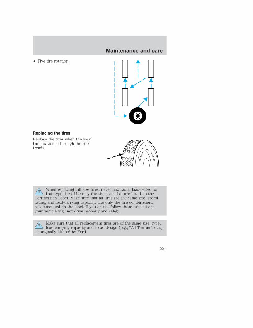
• Five tire rotation
Replacing the tiresReplace the tires when the wearband is visible through the tiretreads.
When replacing full size tires, never mix radial bias-belted, orbias-type tires. Use only the tire sizes that are listed on the
Certification Label. Make sure that all tires are the same size, speedrating, and load-carrying capacity. Use only the tire combinationsrecommended on the label. If you do not follow these precautions,your vehicle may not drive properly and safely.
Make sure that all replacement tires are of the same size, type,load-carrying capacity and tread design (e.g., “All Terrain”, etc.),
as originally offered by Ford.
Maintenance and care
225

Do not replace your tires with “high performance” tires or largersize tires.
Failure to follow these precautions may adversely affect thehandling of the vehicle and make it easier for the driver to lose
control and roll over.
Tires that are larger or smaller than your vehicle’s original tires may alsoaffect the accuracy of your speedometer.
SNOW TIRES AND CHAINS
Snow tires must be the same size and grade as the tires youcurrently have on your vehicle.
The tires on your vehicle have all weather treads to provide traction inrain and snow. However, in some climates, you may need to use snowtires and chains. If you need to use chains, it is recommended that steelwheels (of the same size and specifications) be used as chains may chipaluminum wheels.
Follow these guidelines when using snow tires and chains:
• Use only SAE Class S chains.
• Install chains securely, verifying that the chains do not touch anywiring, brake lines or fuel lines.
• Drive cautiously. If you hear the chains rub or bang against yourvehicle, stop and re-tighten the chains. If this does not work, removethe chains to prevent damage to your vehicle.
• If possible, avoid fully loading your vehicle.
• Remove the tire chains when they are no longer needed. Do not usetire chains on dry roads.
• The suspension insulation and bumpers will help prevent vehicledamage. Do not remove these components from your vehicle whenusing snow tires and chains.
Maintenance and care
226

WHAT YOU SHOULD KNOW ABOUT AUTOMOTIVE FUELS
Important safety precautions
Do not overfill the fuel tank. The pressure in an overfilled tankmay cause leakage and lead to fuel spray and fire.
The fuel system may be under pressure. If the fuel filler cap isventing vapor or if you hear a hissing sound, wait until it stops
before completely removing the fuel filler cap. Otherwise, fuel mayspray out and injure you or others.
If you do not use the proper fuel filler cap, excessive pressure orvacuum in the fuel tank may damage the fuel system or cause
the fuel cap to disengage in a collision, which may result in possiblepersonal injury.
Automotive fuels can cause serious injury or death if misused ormishandled.
Gasoline may contain benzene, which is a cancer-causing agent.
Maintenance and care
227

Observe the following guidelines when handling automotive fuel:
• Extinguish all smoking materialsand any open flames beforefueling your vehicle.
• Always turn off the vehicle beforefueling.
• Automotive fuels can be harmfulor fatal if swallowed. Fuel such asgasoline is highly toxic and ifswallowed can cause death orpermanent injury. If fuel isswallowed, call a physician immediately, even if no symptoms areimmediately apparent. The toxic effects of fuel may not be visible forhours.
• Avoid inhaling fuel vapors. Inhaling too much fuel vapor of any kindcan lead to eye and respiratory tract irritation. In severe cases,excessive or prolonged breathing of fuel vapor can cause seriousillness and permanent injury.
• Avoid getting fuel liquid in your eyes. If fuel is splashed in the eyes,remove contact lenses (if worn), flush with water for 15 minutes andseek medical attention. Failure to seek proper medical attention couldlead to permanent injury.
• Fuels can also be harmful if absorbed through the skin. If fuel issplashed on the skin and/or clothing, promptly remove contaminatedclothing and wash skin thoroughly with soap and water. Repeated orprolonged skin contact with fuel liquid or vapor causes skin irritation.
• Be particularly careful if you are taking “Antabuse” or other forms ofdisulfiram for the treatment of alcoholism. Breathing gasoline vapors,or skin contact could cause an adverse reaction. In sensitiveindividuals, serious personal injury or sickness may result. If fuel issplashed on the skin, promptly wash skin thoroughly with soap andwater. Consult a physician immediately if you experience an adversereaction.
When refueling always shut the engine off and never allowsparks or open flames near the filler neck. Never smoke while
refueling. Fuel vapor is extremely hazardous under certain conditions.Care should be taken to avoid inhaling excess fumes.
Maintenance and care
228

The flow of fuel through a fuel pump nozzle can produce staticelectricity, which can cause a fire if fuel is pumped into an
ungrounded fuel container.
Use the following guidelines to avoid static build-up when filling anungrounded fuel container:
• Place approved fuel container on the ground.
• DO NOT fill a fuel container while it is in the vehicle (including thecargo area).
• Keep the fuel pump nozzle in contact with the fuel container whilefilling.
• DO NOT use a device that would hold the fuel pump handle in the fillposition.
Choosing the right fuelUse only UNLEADED FUEL. The use of leaded fuel is prohibited by lawand could damage your vehicle.
Do not use fuel containing methanol. It can damage critical fuel systemcomponents.
Your vehicle was not designed to use fuel or fuel additives with metalliccompounds, including manganese-based compounds containing MMT.
Repairs to correct the effects of using a fuel for which your vehicle wasnot designed may not be covered by your warranty.
Octane recommendationsYour vehicle is designed to use“Regular” unleaded gasoline withpump (R+M)/2 octane rating of 87.We do not recommend the use ofgasolines labeled as “Regular” thatare sold with octane ratings of 86 or lower in high altitude areas.
Do not be concerned if your engine sometimes knocks lightly. However, ifit knocks heavily under most driving conditions while you are using fuelwith the recommended octane rating, see your dealer or a qualifiedservice technician to prevent any engine damage.
87(R+M)/2 METHOD
Maintenance and care
229

Fuel qualityIf you are experiencing starting, rough idle or hesitation driveabilityproblems during a cold start, try a different brand of “Regular” unleadedgasoline. “Premium” unleaded gasoline is not recommended (particularlyin the United States) because it may cause these problems to becomemore pronounced. If the problems persist, see your dealer or a qualifiedservice technician.
It should not be necessary to add any aftermarket products to your fueltank if you continue to use high quality fuel of the recommended octanerating. Aftermarket products could cause damage to the fuel system.Repairs to correct the effects of using an aftermarket product in yourfuel may not be covered by your warranty.
Many of the world’s automakersissued the World-wide Fuel Charterthat recommends gasolinespecifications to provide improvedperformance and emission controlsystem protection for your vehicle.Gasolines that meet the World-wideFuel Charter should be used whenavailable. Ask your fuel supplierabout gasolines that meet theWorld-wide Fuel Charter. In Canada,look for fuels that display the Auto Makers’ Choice� logo.
Cleaner airFord endorses the use of reformulated “cleaner-burning” gasolines toimprove air quality.
Running out of fuelAvoid running out of fuel because this situation may have an adverseaffect on powertrain components.
If you have run out of fuel:
• You may need to cycle the ignition from OFF to ON several times afterrefueling, to allow the fuel system to pump the fuel from the tank tothe engine.
• Your “Service Engine Soon” indicator may come on. For moreinformation on the “Service Engine Soon” indicator, refer to theInstrumentation chapter.
Maintenance and care
230

Fuel Filler CapYour fuel tank filler cap has an indexed design with a 1/8 turn on/offfeature.
When fueling your vehicle:
1. Turn the engine off.
2. Carefully turn the filler cap counterclockwise 1/8 of a turn until it stops.
3. Pull to remove the cap from the fuel filler pipe.
4. To install the cap, align the tabs on the cap with the notches on thefiller pipe.
5. Turn the filler cap clockwise 1/8 of a turn until it stops.
If the “Service Engine Soon/Check Engine” indicator comes on and stayson after you start the engine, the fuel filler cap may not be properlyinstalled. Turn off the engine, remove the fuel filler cap, align the capproperly and reinstall it.
If you must replace the fuel filler cap, replace it with a fuel fillercap that is designed for your vehicle. The customer warranty maybe void for any damage to the fuel tank or fuel system if thecorrect genuine Ford or Motorcraft fuel filler cap is not used.
The fuel system may be under pressure. If the fuel filler cap isventing vapor or if you hear a hissing sound, wait until it stops
before completely removing the fuel filler cap. Otherwise, fuel mayspray out and injure you or others.
If you do not use the proper fuel filler cap, excessive pressure orvacuum in the fuel tank may damage the fuel system or cause
the fuel cap to disengage in a collision, which may result in possiblepersonal injury.
Fuel FilterFor fuel filter replacement, see your dealer or a qualified servicetechnician. Refer to the scheduled maintenance guide for the appropriateintervals for changing the fuel filter.
Replace the fuel filter with an authorized Motorcraft part. Thecustomer warranty may be void for any damage to the fuel systemif an authorized Motorcraft fuel filter is not used.
Maintenance and care
231

ESSENTIALS OF GOOD FUEL ECONOMY
Measuring techniquesYour best source of information about actual fuel economy is you, thedriver. You must gather information as accurately and consistently aspossible. Fuel expense, frequency of fillups or fuel gauge readings areNOT accurate as a measure of fuel economy. We do not recommendtaking fuel economy measurements during the first 1 600 km (1 000miles) of driving (engine break-in period). You will get a more accuratemeasurement after 3 000 km–5 000 km (2 000 miles-3 000 miles).
Filling the tankThe advertised fuel capacity of the fuel tank on your vehicle is equal tothe rated refill capacity of the fuel tank as listed in the Refill capacitiessection of the Capacities and specifications chapter.
The advertised capacity is the amount of the indicated capacity and theempty reserve combined. Indicated capacity is the difference in theamount of fuel in a full tank and a tank when the fuel gauge indicatesempty. Empty reserve is the small amount of fuel remaining in the fueltank after the fuel gauge indicates empty.
The amount of usable fuel in the empty reserve varies and shouldnot be relied upon to increase driving range. When refueling yourvehicle after the fuel gauge indicates empty, you might not beable to refuel the full amount of the advertised capacity of thefuel tank due to the empty reserve still present in the tank.
For consistent results when filling the fuel tank:
• Turn the engine/ignition switch to the off position prior to refueling,an error in the reading will result if the engine is left running.
• Use the same filling rate setting (low — medium — high) each timethe tank is filled.
• Allow no more than 2 automatic click-offs when filling.
• Always use fuel with the recommended octane rating.
• Use a known quality gasoline, preferably a national brand.
• Use the same side of the same pump and have the vehicle facing thesame direction each time you fill up.
• Have the vehicle loading and distribution the same every time.
Your results will be most accurate if your filling method is consistent.
Maintenance and care
232

Calculating fuel economy1. Fill the fuel tank completely and record the initial odometer reading(in kilometers or miles).
2. Each time you fill the tank, record the amount of fuel added (in litersor gallons).
3. After at least three to five tank fill-ups, fill the fuel tank and recordthe current odometer reading.
4. Subtract your initial odometer reading from the current odometerreading.
5. Follow one of the simple calculations in order to determine fueleconomy:
Multiply liters used by 100, then divide by total kilometerstraveled.
Divide total miles traveled by total gallons used.
Keep a record for at least one month and record the type of driving (cityor highway). This will provide an accurate estimate of the vehicle’s fueleconomy under current driving conditions. Additionally, keeping recordsduring summer and winter will show how temperature impacts fueleconomy. In general, lower temperatures give lower fuel economy.
Driving style — good driving and fuel economy habitsGive consideration to the lists that follow and you may be able to changea number of variables and improve your fuel economy.
Habits• Smooth, moderate operation can yield up to 10% savings in fuel.
• Steady speeds without stopping will usually give the best fueleconomy.
• Idling for long periods of time (greater than one minute) may wastefuel.
• Anticipate stopping; slowing down may eliminate the need to stop.
• Sudden or hard accelerations may reduce fuel economy.
• Slow down gradually.
Maintenance and care
233
• Driving at reasonable speeds (traveling at 88 km/h [55 mph] uses 15%less fuel than traveling at 105 km/h [65 mph]).
• Revving the engine before turning it off may reduce fuel economy.
• Using the air conditioner or defroster may reduce fuel economy.
• You may want to turn off the speed control in hilly terrain ifunnecessary shifting between third and fourth gear occurs.Unnecessary shifting of this type could result in reduced fueleconomy.
• Warming up a vehicle on cold mornings is not required and mayreduce fuel economy.
• Resting your foot on the brake pedal while driving may reduce fueleconomy.
• Combine errands and minimize stop-and-go driving.
Maintenance• Keep tires properly inflated and use only recommended size.
• Operating a vehicle with the wheels out of alignment will reduce fueleconomy.
• Perform all regularly scheduled maintenance items. Follow therecommended maintenance schedule and owner maintenance checksfound in your vehicle scheduled maintenance guide.
Conditions• Heavily loading a vehicle or towing a trailer may reduce fuel economy
at any speed.
• Carrying unnecessary weight may reduce fuel economy (approximately0.4 km/L [1 mpg] is lost for every 180 kg [400 lb] of weight carried).
• Adding certain accessories to your vehicle (for example bugdeflectors, rollbars/light bars, running boards, ski/luggage racks) mayreduce fuel economy.
• Using fuel blended with alcohol may lower fuel economy.
• Fuel economy may decrease with lower temperatures during the first12–16 km (8–10 miles) of driving.
• Driving on flat terrain offers improved fuel economy as compared todriving on hilly terrain.
Maintenance and care
234

• Transmissions give their best fuel economy when operated in the topcruise gear and with steady pressure on the gas pedal.
• Four-wheel-drive operation (if equipped) is less fuel efficient thantwo-wheel-drive operation.
• Close windows for high speed driving.
EPA window stickerEvery new vehicle should have the EPA window sticker. Contact yourdealer if the window sticker is not supplied with your vehicle. The EPAwindow sticker should be your guide for the fuel economy comparisonswith other vehicles.
It is important to note the box in the lower left corner of the windowsticker. These numbers represent the Range of L/100 km (MPG)expected on the vehicle under optimum conditions. Your fuel economymay vary depending upon the method of operation and conditions.
EMISSION CONTROL SYSTEMYour vehicle is equipped with various emission control components and acatalytic converter which will enable your vehicle to comply withapplicable exhaust emission standards. To make sure that the catalyticconverter and other emission control components continue to workproperly:
• Use only the specified fuel listed.
• Avoid running out of fuel.
• Do not turn off the ignition while your vehicle is moving, especially athigh speeds.
• Have the items listed in your scheduled maintenance guide performedaccording to the specified schedule.
The scheduled maintenance items listed in the scheduled maintenanceguide are essential to the life and performance of your vehicle and to itsemissions system.
If other than Ford, Motorcraft or Ford-authorized parts are used formaintenance replacements or for service of components affectingemission control, such non-Ford parts should be equivalent to genuineFord Motor Company parts in performance and durability.
Maintenance and care
235
Do not park, idle, or drive your vehicle in dry grass or other dryground cover. The emission system heats up the engine
compartment and exhaust system, which can start a fire.
Illumination of the “Service Engine Soon” light, charging system warninglight or the temperature warning light, fluid leaks, strange odors, smokeor loss of engine power, could indicate that the emission control systemis not working properly.
Exhaust leaks may result in entry of harmful and potentiallylethal fumes into the passenger compartment.
Do not make any unauthorized changes to your vehicle or engine. Bylaw, vehicle owners and anyone who manufactures, repairs, services,sells, leases, trades vehicles, or supervises a fleet of vehicles are notpermitted to intentionally remove an emission control device or preventit from working. Information about your vehicle’s emission system is onthe Vehicle Emission Control Information Decal located on or near theengine. This decal identifies engine displacement and gives some tune upspecifications.
Please consult your Warranty Guide for complete emission warrantyinformation.
Readiness for Inspection/Maintenance (I/M) testingIn some localities, it may be a legal requirement to pass an I/M test ofthe on-board diagnostics system. If your “Check Engine/Service EngineSoon” light is on, refer to the description in the Warning lights andchimes section of the Instrumentation chapter. Your vehicle may notpass the I/M test with the “Check Engine/Service Engine Soon” light on.
If the vehicle’s powertrain system or its battery has just been serviced,the on-board diagnostics system is reset to a “not ready for I/M test”condition. To ready the on-board diagnostics system for I/M testing, aminimum of 30 minutes of city and highway driving is necessary asdescribed below:
• First, at least 10 minutes of driving on an expressway or highway.
• Next, at least 20 minutes driving in stop-and-go, city-type traffic withat least four idle periods.
Maintenance and care
236

Allow the vehicle to sit for at least eight hours without starting theengine. Then, start the engine and complete the above driving cycle. Theengine must warm up to its normal operating temperature. Once started,do not turn off the engine until the above driving cycle is complete.
BULBS
Replacing exterior bulbsCheck the operation of the following lamps frequently:
• Headlamps
• High-mount brakelamp
• Brakelamps
• Turn signals
• License plate lamp
• Tail lamps
• Back-up lamps
Do not remove lamp bulbs unless they can be replaced immediately withnew ones. If a bulb is removed for an extended period of time,contaminants may enter the lamp housings and affect lamp performance.
Replacing headlamp bulbs (aerodynamic)1. Make sure that the headlamp control is in the OFF position.
2. Open the hood.
3. Disconnect the electrical connector from the bulb by pulling rearward.
4. Remove bulb retainer ring byturning it counterclockwise, thenslide the ring off the plastic base.
5. Without turning, carefully pullbulb out of headlamp assembly.
Maintenance and care
237
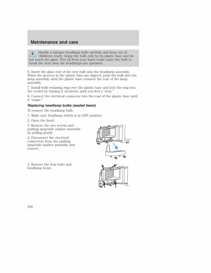
Handle a halogen headlamp bulb carefully and keep out ofchildren’s reach. Grasp the bulb only by its plastic base and do
not touch the glass. The oil from your hand could cause the bulb tobreak the next time the headlamps are operated.
6. Insert the glass end of the new bulb into the headlamp assembly.When the grooves in the plastic base are aligned, push the bulb into thelamp assembly until the plastic base contacts the rear of the lampassembly.
7. Install bulb retaining ring over the plastic base and lock the ring intothe socket by turning it clockwise until you feel a “stop.”
8. Connect the electrical connector into the rear of the plastic base untilit “snaps.”
Replacing headlamp bulbs (sealed beam)To remove the headlamp bulb:
1. Make sure headlamp switch is in OFF position.
2. Open the hood.
3. Remove the two screws andparking lamp/side marker assemblyby pulling gently
4. Disconnect the electricalconnectors from the parkinglamp/side marker assembly andremove.
5. Remove the four bolts andheadlamp bezel.
Maintenance and care
238

6. Remove the four screws and theheadlamp retaining ring fromheadlamp.
7. Disconnect the electricalconnector and remove headlamp.
To install the new headlamp, reverse the removal procedure.
Replacing front parking/turn signal bulbs1. Make sure headlamp switch is in OFF position.
2. Open the hood.
3. Remove the two screws andcarefully disengage parkinglamp/turn signal assembly from thevehicle.
4. Rotate bulb socketcounterclockwise about 1⁄4 turn andremove from lamp assembly.
Maintenance and care
239

5. Carefully pull bulb straight out ofthe socket and push in the newbulb.
6. Install the bulb socket in lampassembly by turning clockwise.
7. Align the lamp assembly on thevehicle.
8. Install two screws on parkinglamp/turn signal assembly.
Replacing tail lamp/turn/backup lamp bulbs — F250/F350 onlyThe tail lamp/backup lamp bulbs arelocated in the same portion of thetail lamp assembly, one just belowthe other. Follow the same steps toreplace either bulb:
1. Open the tailgate to expose thelamp assemblies.
2. Remove the two bolts from thetail lamp assembly.
3. Carefully pull the lamp assemblyfrom the tailgate pillar by releasingthe two retaining tabs.
4. Twist the bulb socket 1⁄4 turn counterclockwise and remove from lampassembly.
5. Pull the bulb straight out of the socket and push in the new bulb.
6. Install bulb socket in lamp assembly by turning clockwise.
7. Carefully install the tail lamp assembly on tailgate pillar snapping thetwo retaining tabs into place.
8. Secure the tail lamp with two bolts.
Maintenance and care
240

Replacing brake/tail/backup lamp bulbs — F450/F550 onlyThe brake/tail/backup lamp bulbsare located in the same portion ofthe tail lamp assembly. Follow thesame steps to replace either bulb:
1. Remove the four screws and thelamp lens from lamp assembly.
2. Carefully pull the bulb straightout of the socket and push in thenew bulb.
3. Install the lens on the lampassembly with the four screws.
Replacing cargo lamp and high-mount brakelamp bulbsTo remove the lamp assembly:
1. Remove the two screws and lampassembly from vehicle as wiringpermits.
2. Remove the bulb socket byrotating counterclockwise andpulling it out of the lamp assembly.
3. Pull the bulb straight out of thesocket and push in the new bulb.
To install the brakelamp assembly:
1. Install the bulb into the lampassembly and rotate clockwise.
2. Install the lamp assembly on the vehicle with two screws.
Maintenance and care
241

Replacing roof marker bulbsTo change the cab marker bulbs:
1. Remove the screw and lens fromthe lamp assembly.
2. Carefully pull the bulb straightout of the socket and push in thenew bulb.
3. Install lens on lamp assembly withscrew.
Replacing foglamp bulbs (if equipped)1. Remove the bulb socket from thefoglamp by turningcounterclockwise.
2. Disconnect the electricalconnector from the foglamp bulb.
3. Connect the new foglamp bulb to the electrical connector.
4. Install the bulb socket in the foglamp by turning clockwise.
Replacing license plate lamp bulbsThe license plate bulbs are locatedbehind the rear bumper. To changethe license plate lamp bulbs:
1. Reach behind the rear bumper tolocate the bulb.
2. Twist the bulb socketcounterclockwise and carefully pullto remove it from the lampassembly.
3. Pull out the old bulb from thesocket and push in the new bulb.
4. Install the bulb socket in lamp assembly by turning it clockwise.
Maintenance and care
242

Using the right bulbsReplacement bulbs are specified in the chart below. Headlamp bulbsmust be marked with an authorized “D.O.T.” for North America and an“E” for Europe to assure lamp performance, light brightness and patternand safe visibility. The correct bulbs will not damage the lamp assemblyor void the lamp assembly warranty and will provide quality bulb burntime.
Function Number of
bulbs
Trade number
Headlamps (aerodynamic) 2 9007Headlamps (sealed beam) 2 H6054Park/turn 2 3157Sidemarker 2 194Tail/stop/turn/sidemarker 2 3157 KBackup 2 3156KHigh-mount stoplamp 1 921Foglamp 2 899License plate lamp 2 168Cargo lamp 2 906Roofmarker 5 194Rear fender clearance 4 (a)
Interior visor lamp (if equipped) 4 194Rear identification 3 194All replacement bulbs are clear in color except where noted.To replace all instrument panel lights - see your dealer(a) Replace entire lamp assembly; bulb is not serviceable.
AIMING THE HEADLAMPSThe headlamps on your vehicle are properly aimed at the assembly plant.
If your vehicle has been in an accident the alignment of your headlampsshould be checked by a qualified service technician.
CLEANING AND CARING FOR YOUR VEHICLERefer to the Customer Assistance chapter for a list of Ford-approvedcleaners, polishes and waxes.
Maintenance and care
243

Washing your vehicleWash your vehicle regularly withcold or lukewarm water. Never usestrong detergents or soap. If yourvehicle is particularly dirty, use aquality car wash detergent. Alwaysuse a clean sponge, washing gloveor similar device and plenty of waterfor best results. To avoid spots,avoid washing when the hood is stillwarm, immediately after or duringexposure to strong sunlight.
During winter months, it is especially important to wash the vehicle on aregular basis. Large quantities of dirt and road salt are difficult toremove and also cause damage to the vehicle.
Any gasoline spilled on the vehicle or deposits such as bird droppingsshould be washed and sponged off as soon as possible. Deposits notremoved promptly can cause damage to the vehicle’s paintwork.
Remove any exterior accessories (such as antennas) and fold in the sideview mirrors before entering a car wash. If you have wax applied to thevehicle at a commercial car wash, it is recommended that you clean thewiper blades and windshield as described in Cleaning the wiper bladesand windshield.
After washing, apply the brakes several times to dry them.
UnderbodyFlush the complete underside of vehicle frequently. Keep body drainholes unplugged. Inspect for road damage.
Waxing your vehicleWaxing your vehicle on a regular basis will reduce minor scratches andpaint damage.
Wax when water stops beading on the surface. This could be every threeor four months, depending on operating conditions.
Use only carnauba or synthetic-based waxes. Use a cleaning fluid with aclean cloth to remove any bugs before waxing your vehicle. Use tarremover to remove any tar spots.
Maintenance and care
244

Avoid getting wax on the windshield, or on any surfaces which appearcoarse or bumpy. If you have wax applied at a commercial car wash, it isrecommended that you clean the wiper blades and windshield asdescribed in Cleaning the wiper blades and windshield.
Repairing paint chipsMinor scratches or paint damage from road debris may be repaired withthe Ultra Touch Prep and Finishing Kit (F7AZ-19K507–BA), LacquerTouch-up Paint (ALBZ-19500–XXXXA), or Exterior Acrylic SprayLacquer (ALAZ-19500–XXXXA) from the Ford Car Care Chemicals line.Please note that the part numbers (shown as XXXX above) will vary withyour vehicle’s specific coloring. Observe the application instructions onthe products.
Remove particles such as bird droppings, tree sap, insect remains, tarspots, road salt and industrial fallout immediately.
Cleaning the wheelsWash with the same detergent as the body of your vehicle. Do not useacid-based or alcohol-based wheel cleaners, steel wool, fuel or strongdetergents. Never use abrasives that will damage the finish of specialwheel surfaces. Use a tar remover to remove grease and tar.
The brushes used in some automatic car washes may damage the finishon your wheels. Before going to a car wash, find out if the brushes areabrasive.
Maintenance and care
245

Cleaning the engineEngines are more efficient when they are clean because grease and dirtbuildup keep the engine warmer than normal. When washing:
• Take care when using a power washer to clean the engine. The highpressure fluid could penetrate the sealed parts and cause damage.
• Do not spray with cold water to avoid cracking the engine block orother engine components.
• Never wash or rinse the engine while it is running; water in therunning engine may cause internal damage.
Cleaning non-painted plastic exterior partsUse vinyl cleaner for routine cleaning. Clean with a tar remover ifnecessary. Do not clean plastic parts with thinners, solvents orpetroleum-based cleaners.
Cleaning the exterior lampsWash with the same detergent as the exterior of your vehicle. Ifnecessary, use a tar remover such as Ford Extra Strength Tar and RoadOil Remover (B7A-19520–AA).
To avoid scratching the lamps, do not use a dry paper towel, chemicalsolvents or abrasive cleaners.
Maintenance and care
246

Cleaning the windshield, wiper blades and rear windowIf the wiper blades do not wipe properly, clean the wiper blade rubberelement with undiluted windshield washer solution or a mild detergent.To avoid damaging the blades, do not use fuel, kerosene, paint thinner orother solvents.
If the wiper still does not wipe properly, this could be caused bysubstances on the windshield or rear window such as tree sap and somehot wax treatments used by commercial car washes. Clean the outside ofthe windshield or rear window with a non-abrasive cleaner such as FordUltra-Clear Spray Glass Cleaner, (E4AZ-19C507–AA), available from yourFord Dealer. Do not use abrasive cleansers on glass as they may causescratches. The windshield or rear window is clean if beads do not formwhen you rinse it with water. The windshield, rear window and wiperblades should be cleaned on a regular basis, and blades or rubberelements replaced when worn.
Cleaning the instrument panelClean with a damp cloth, then dry with a dry cloth.
Avoid cleaner or polish that increases the gloss of the upper portion ofthe instrument panel. The dull finish in this area helps protect the driverfrom undesirable windshield reflection.
Do not use chemical solvents or strong detergents when cleaningthe steering wheel or instrument panel to avoid contamination of
the air bag system.
Cleaning the instrument cluster lensClean with a damp cloth, then dry with a dry cloth.
Do not use household or glass cleaners as these may damage the lens.
Cleaning the interior fabricRemove dust and loose dirt with a whisk broom or a vacuum cleaner.Remove fresh spots immediately. Do not use household or glass cleaners.These agents can stain and discolor the fabric. Use a mild soap andwater solution if necessary.
Maintenance and care
247
Cleaning and maintaining the safety beltsClean the safety belts with a mild soap solution recommended forcleaning upholstery or carpets. Do not bleach or dye the belts, becausethese actions may weaken the belt webbing.
Check the safety belt system periodically to make sure there are nonicks, tears or cuts. If your vehicle has been involved in an accident,refer to the Safety belt maintenance section in the Seating and safetyrestraints chapter.
Cleaning leather seats (if equipped)To clean, simply use a soft cloth dampened with water and a mild soap.Wipe the leather again with a damp cloth to remove soap residue. Drywith a soft cloth. For tougher soiling concerns, Ford recommends usingthe Deluxe Leather Care Kit F8AZ-19G253–AA, which is available fromyour Ford Dealer. This mild cleaner and special pad, cleans the leatherand maintains its natural beauty. Follow the instructions on the cleanerlabel. Regular cleaning of your leather upholstery helps maintain itsresiliency and color.
Do not use household cleaning products, alcohol solutions,solvents or cleaners intended for rubber, vinyl or plastics.
Maintenance and care
248
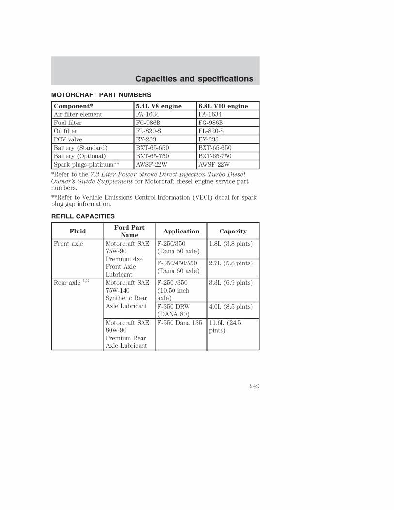
MOTORCRAFT PART NUMBERS
Component* 5.4L V8 engine 6.8L V10 engine
Air filter element FA-1634 FA-1634Fuel filter FG-986B FG-986BOil filter FL-820-S FL-820-SPCV valve EV-233 EV-233Battery (Standard) BXT-65-650 BXT-65-650Battery (Optional) BXT-65-750 BXT-65-750Spark plugs-platinum** AWSF-22W AWSF-22W
*Refer to the 7.3 Liter Power Stroke Direct Injection Turbo DieselOwner’s Guide Supplement for Motorcraft diesel engine service partnumbers.
**Refer to Vehicle Emissions Control Information (VECI) decal for sparkplug gap information.
REFILL CAPACITIES
FluidFord Part
NameApplication Capacity
Front axle Motorcraft SAE75W-90Premium 4x4Front AxleLubricant
F-250/350(Dana 50 axle)
1.8L (3.8 pints)
F-350/450/550(Dana 60 axle)
2.7L (5.8 pints)
Rear axle 1,2 Motorcraft SAE75W-140Synthetic RearAxle Lubricant
F-250 /350(10.50 inchaxle)
3.3L (6.9 pints)
F-350 DRW(DANA 80)
4.0L (8.5 pints)
Motorcraft SAE80W-90Premium RearAxle Lubricant
F-550 Dana 135 11.6L (24.5pints)
Capacities and specifications
249

FluidFord Part
NameApplication Capacity
Brake fluid HighPerformanceDOT 3 MotorVehicle BrakeFluid
All Fill to line onreservoir
Engine coolant 3 MotorcraftPremium EngineCoolant(green-colored)or MotorcraftPremium GoldEngine Coolant(yellow-colored)
5.4L V8 enginewith A/C
25.0L (26.4quarts)
6.8L V10 engine 27.0L (28.5quarts)
Engine oil(includes filterchange)-Gasengines
Motorcraft SAE5W-20 SuperPremium MotorOil
All 5.7L (6.0quarts)
Engine oil(includes filterchange)-Dieselengine
Refer to your 7.3L Diesel Supplement
Capacities and specifications
250

FluidFord Part
NameApplication Capacity
Fuel tank N/A Mid-ship tank(optional onChassis Cab)
71.9L (19.0gallons)
Right sidesaddle mountedtank (optionalon Chassis Cab)
87.1L (23.0gallons)
Short box 109.8L (29.0gallons)
Long box 143.9L (38.0gallons)
Aft axle 151.4L (40.0gallons)
Power steeringfluid
MotorcraftMERCON� ATF
All Fill to line onreservoir
Transfer casefluid
MotorcraftMERCON� ATF
4x4 vehicles 1.9L (2.0quarts)
Transmissionfluid 4
SyntheticMERCON� ATF
5-speed manual 3.2L (3.4quarts) 5
MotorcraftMERCON� ATF
6-speed manual 5.5L (5.8quarts) 5
Automatic 16.7L (17.7quarts) 6
Windshieldwasher fluid
Ultra-ClearWindshieldWasherConcentrate
All 4.0L (4.25quarts)
1Your vehicle’s rear axle(s) may be filled with a synthetic lubricant thatmay require a lubricant change. Refer to the scheduled maintenanceguide. Axle lubricant quantities should not need to be checked unless aleak is suspected, service is required or the axle assembly has beensubmerged in water. The axle lubricant should be changed any time therear axle has been submerged in water.
Capacities and specifications
251

2Add 236 ml (8 oz.) of Additive Friction Modifier C8AZ-19B546-A orequivalent meeting Ford Specification EST-M2C118-A for complete refillof Traction-Lok axles.3Add the coolant type originally equipped in your vehicle.4Ensure the correct automatic transmission fluid is used. Transmissionfluid requirements are indicated on the dipstick or on the dipstickhandle. Check the container to verify the fluid being added is of thecorrect type. Refer to your scheduled maintenance guide to determinethe correct service interval.
Some transmission fluids may be labeled as dual usage, such asMERCON� and MERCON� V. These dual usage fluids are not to be usedin an automatic transmission that requires use of the MERCON� typefluid. However, these dual usage fluids may be used in transmissions thatrequire the MERCON� V type fluid.
MERCON� and MERCON� V type fluids are not interchangeable.DO NOT mix MERCON� and MERCON� V. Use of a transmissionfluid that indicates dual usage (MERCON� and MERCON� V) inan automatic transmission application requiring MERCON� maycause transmission damage. Use of any fluid other than therecommended fluid may cause transmission damage.5Service refill capacity is determined by filling the transmission to thebottom of the filler hole with the vehicle on a level surface.6Indicates only approximate dry-fill capacity. Some applications may varybased on cooler size and if equipped with an in-tank cooler. The amountof transmission fluid and fluid level should be set by the indication onthe dipstick’s normal operating range.
Capacities and specifications
252

LUBRICANT SPECIFICATIONS
Item
Ford part
name or
equivalent
Ford part
number
Ford
specification
Front axle(4X4)
Motorcraft SAE75W-90Premium 4x4Front AxleLubricant
XY-75W90-TQL WSP-M2C201-A
Rear axle
Motorcraft SAE75W-140 HighPerformanceSynthetic RearAxle Lube 1
F1TZ-19580-B WSL-M2C192-A
Motorcraft SAE80W-90Premium RearAxle Lubricant(Dana 135axles) 1
XY-80W90-QL WSP-M2C197-A
Brake fluid andclutch fluid (ifequipped)
HighPerformanceDOT 3 MotorVehicle BrakeFluid
C6AZ-19542-AB ESA-M6C25-Aand DOT 3
Engine coolant MotorcraftPremium EngineCoolant(green-colored)
VC-4–A (inCanada,MotorcraftCXC-10)
ESE-M97B44-A
MotorcraftPremium GoldEngine Coolant(yellow-colored)
VC-7–A WSS-M97B51-A1
Capacities and specifications
253

Item
Ford part
name or
equivalent
Ford part
number
Ford
specification
Engine oil
Motorcraft SAE5W-20 SuperPremium MotorOil
XO-5W20-QSP WSS-M2C153-Hand APICertificationMark
Hinges, latches,striker plates,fuel filler doorhinge and seattracks
Multi-PurposeGrease
DOAZ-19584-AAorF5AZ-19G209-AA
ESB-M1C93-B orESR-M1C159-A
Lock cylindersMotorcraftpenetrating andlock lubricant
Motorcraft XL-1 none
Transmission/steering/parkingbrake linkagesand pivots,brake and clutchpedal shaft (ifequipped)
PremiumLong-Life Grease
XG-1-C orXG-1-K
ESA-M1C75-B
Power steeringfluid andtransfer casefluid (ifequipped)
MotorcraftMERCON� ATF
XT-2-QDX MERCON�
Manualtransmission(5-speed)
SyntheticMERCON� ATF2
E6AZ-19582-B MERCON�
Manualtransmission(6-speed)
MotorcraftMERCON� ATF2
XT-2-QDX MERCON�
Capacities and specifications
254

Item
Ford part
name or
equivalent
Ford part
number
Ford
specification
Automatictransmission
MotorcraftMERCON� ATF2
XT-2-QDX MERCON�
Windshieldwasher fluid
Ultra-clearWindshieldWasherConcentrate
C9AZ-19550-AC ESR-M17P5-A
1Add 236 ml (8 oz.) of Additive Friction Modifier C8AZ-19B546-A orequivalent meeting Ford specification EST-M2C118-A for complete refillof Traction-Lok axles. Ford design rear axles contain a syntheticlubricant that does not require changing unless the axle has beensubmerged in water. Dana rear axles also contain a synthetic lubricantbut do require a change. Refer to your “Service Guide” for changeintervals on Dana rear axles.2Ensure the correct automatic transmission fluid is used. Transmissionfluid requirements are indicated on the dipstick or on the dipstickhandle. Check the container to verify the fluid being added is of thecorrect type. Refer to your scheduled maintenance guide to determinethe correct service interval.
Some transmission fluids may be labeled as dual usage, such asMERCON� and MERCON� V. These dual usage fluids are not to be usedin an automatic transmission that requires use of the MERCON� typefluid. However, these dual usage fluids may be used in transmissions thatrequire the MERCON� V type fluid.
MERCON� and MERCON� V type fluids are not interchangeable.DO NOT mix MERCON� and MERCON� V. Use of a transmissionfluid that indicates dual usage (MERCON� and MERCON� V) inan automatic transmission application requiring MERCON� maycause transmission damage. Use of any fluid other than therecommended fluid may cause transmission damage.
Capacities and specifications
255

ENGINE DATA
Engine 5.4L V8 engine 6.8L V10 engine
Cubic inches 330 415Required fuel 87 octane 87 octaneFiring order 1-3-7-2-6-5-4-8 1-6-5-10-2-7-3-8-4-9
Spark plug gap1.3-1.4 mm(0.052-0.056 inch)
1.3-1.4 mm(0.052-0.056 inch)
Ignition system Coil on plug Coil on plugCompression ratio 9.0:1 9.0:1
VEHICLE DIMENSIONS
F250–except Crew Cab
Dimension Body style
Regular
Cab 4x2
Regular
Cab 4x4
Super Cab
4x2
Super Cab
4x4
(1) Overallheight
1 864 mm(74 in)
1 958 mm(77.1 in)
1 870 mm(73.6 in)
1 964 mm(77.3 in)
(2) Track(Front /Rear)
1 736.3 mm(68.3 in) /1 729.3 mm(68 in)
1 736.3 mm(68.3 in) /1 729.3 mm(68 in)
1 736.3 mm(68.3 in) /1 729.3 mm(68 in)
1 736.3 mm(68.3 in) /1 729.3 mm(68 in)
(3) Overallwidth
2 031 mm(79.9 in)
2 031 mm(79.9 in)
2 031 mm(79.9 in)
2 031 mm(79.9 in)
(4)Wheelbase
3 479.8 mm(137 in)
3 479.8 mm(137 in)
3 601.7 mm(141.8 in)a
4 013.2 mm(158 in)b
3 601.7 mm(141.8 in)a
4 013.2 mm(158 in)b
(5) Overalllength
5 646 mm(222.2 in)
5 757 mm(226.6 in)
5 876 mm(231.3 in)a
6 177 mm(243.1 in)b
5 879 mm(231.4 in)a
6 180 mm(243.3 in)b
aShort wheel basebLong wheel base
Capacities and specifications
256

F250-Crew Cab
Dimension Body style
Crew Cab 4x2 Crew Cab 4x4
(1) Overall height 1 960 mm (77.2 in)a/1 883 mm (74.1 in)b
2 053mm (80.8 in)a/2 052 mm (80.8 in)b
(2) Track (Front /Rear)
1 745 mm (68.7 in)/1 729 mm (68.1 in)a,b
1 736 mm (68.4 in)/1 729 mm (68.1 in)a,b
(3) Overall width 1 988 mm (78.3 in)a,b 1 988 mm (78.3 in)a,b
(4) Wheelbase 3 967 mm (156.2 in )a/4 379 mm (172.4 in)b
3 967 mm (156.2 in )a/4 379 mm (172.4 in)b
(5) Overall length 6 242 mm (245.8 in)a/6 654 mm (262.0 in)b
6 242 mm (245.8 in)a/6 654 mm (262.0 in)b
aShort wheel basebLong wheel base
F350–except Crew Cab
Dimension Body style
Chassis
Cab
Regular
Cab
Super Cab
4x2
Super Cab
4x4
(1) Overallheight
1 972 mm(77.6 in)
1 860 mm(73.2 in)c,e
1 865 mm(73.4 in)a
1 861 mm(73.6 in)b
1 960 mm(77.2 in)
(2) Track(Front /Rear)
1 736.3 mm(68.3 in) /1 879.6 mm(74.0 in)
1 736.3 mm(68.3 in) /1 729.3 mm(68.0 in)
1 736.3 mm(68.3 in) /1 729.3 mm(68.0 in)a,c
1 736.3 mm(68.3 in) /1879.6 mm(74.0 in)b,d
1 737.3 mm(68.4 in) /1 729.3 mm(68.0 in)
(3) Overallwidth
2 025 mm(79.7 in)
2 031 mm(79.9 in)
2 031 mm(79.9 in)
2 031 mm(79.9 in)
Capacities and specifications
257

Dimension Body style
Chassis
Cab
Regular
Cab
Super Cab
4x2
Super Cab
4x4
(4)Wheelbase
3 576.3 mm(140.8 in)
3 479.8 mm(137.0 in)
3 601 mm(141.8 in)a/4 013.2 mm(158.0 in)b
3 601 mm(141.8 in)a/4 013.2 mm(158.0 in)b
(5) Overalllength
5 732 mm(225.7 in)
5 754 mm(226.5 in)
5 879 mm(231.4 in)a/6 288 mm(247.6 in)b
6 291 mm(247.7 in)
aShort wheel basebLong wheel basecSingle rear wheelsdDual rear wheels
F350-Crew Cab
Dimension Body style
Crew Cab 4x2 Crew Cab 4x4
(1) Overall height 1 929 mm (75.9 in) 2 038 mm (80.2 in)(2) Track (Front /Rear)
1 745 mm (68.7 in)/1 729 mm (68.1 in)a,b
1 736 mm (68.4 in)/1 729 mm (68.1 in)a,b
(3) Overall width 1 988 mm (78.3 in)a,b 2 077 mm (79.0 in)a,b
(4) Wheelbase 3 967 mm (156.2 in)a/4 379 mm (172.4in)b
3 967 mm (156.2 in)a/4 379 mm (172.4in)b
(5) Overall length 6 242 mm (245.8in)a/6 654 mm (262.0in)b
6 242 mm (245.8in)a/6 654 mm (262.0in)b
aShort wheel basebLong wheel base
Capacities and specifications
258

F450
Dimension Body style
Chassis
Cab 4x2
Chassis
Cab 4x4
Crew Cab
4x2
Crew Cab
4x4
(1) Overallheight
2 044 mm(80.5 in)
2 051 mm(80.7 in)
2 053 mm(80.8 in)
2 056 mm(80.9 in)
(2) Track(Front /Rear)
1 736 mm(68.4 in) /1 610 mm(63.4 in)
1 736 mm(68.4 in) /1 610 mm(63.4 in)
1 736 mm(68.4 in) /1 610 mm(63.4 in)
1 736 mm(68.4 in) /1 610 mm(63.4 in)
(3) Overallwidth
2 025 mm(79.7 in)
2 376 mm(93.5 in)
2 376 mm(93.5 in)
2 376 mm(93.5 in)
(4)Wheelbase
3 576 mm(140.8 in)
4 186 mm(164.8 in)
4 475 mm(176.2 in)
4 475 mm(176.2 in)
(5) Overalllength
5 732 mm(225.6 in)a
6 341 mm(249.6 in)b
5 733 mm(225.7 in)a
6 343 mm(249.7 in)b
5 733 mm(225.7 in)a
6 343 mm(249.7 in)b
5 733 mm(225.7 in)a
6 343 mm(249.7 in)b
aShort wheel basebLong wheel base
F550
Dimension Body style
Chassis
Cab 4x2
Chassis
Cab 4x4
Crew Cab
4x2
Crew Cab
4x4
(1) Overallheight
2 076 mm(81.7 in)
2 075 mm(81.6 in)
2 067 mm(81.4 in)
2 066 mm(81.3 in)
(2) Track(Front /Rear)
1 736 mm(68.3 in) /1 879 mm(74 in)
1 736 mm(68.3 in) /1 879 mm(74 in)
1 736 mm(68.4 in) /1 610 mm(63.4 in)
1 736 mm(68.4 in) /1 610 mm(63.4 in)
(3) Overallwidth
2 025 mm(79.7 in)
2 376 mm(93.5 in)
2 376 mm(93.5 in)
2 376 mm(93.5 in)
(4)Wheelbase
3 576 mm(140.8 in)
3 576 mm(140.8 in)
4 475 mm(176.2 in)
4 475 mm(176.2 in)
Capacities and specifications
259
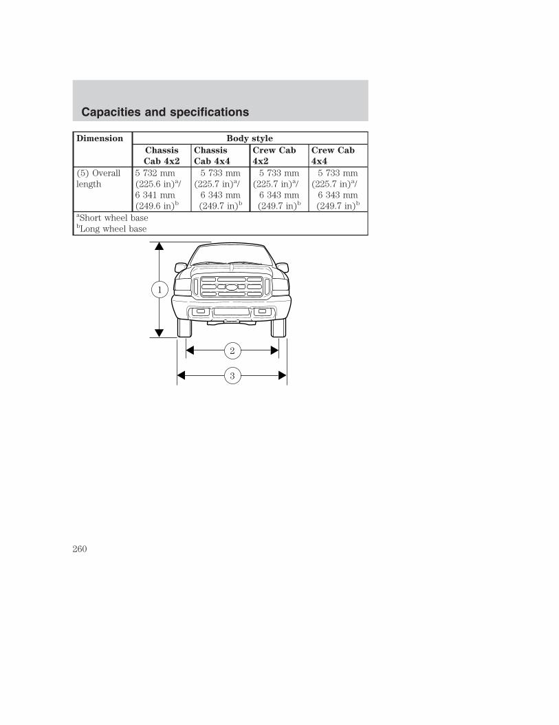
Dimension Body style
Chassis
Cab 4x2
Chassis
Cab 4x4
Crew Cab
4x2
Crew Cab
4x4
(5) Overalllength
5 732 mm(225.6 in)a/6 341 mm(249.6 in)b
5 733 mm(225.7 in)a/
6 343 mm(249.7 in)b
5 733 mm(225.7 in)a/
6 343 mm(249.7 in)b
5 733 mm(225.7 in)a/
6 343 mm(249.7 in)b
aShort wheel basebLong wheel base
3
2
1
Capacities and specifications
260

IDENTIFYING YOUR VEHICLE
Certification labelThe National Highway Traffic SafetyAdministration Regulations requirethat a Certification label be affixedto a vehicle and prescribe where theCertification label may be located.The Certification label is located onthe front door latch pillar on thedriver’s side.
5
4
Capacities and specifications
261
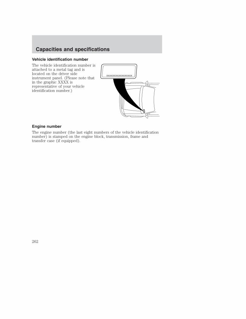
Vehicle identification numberThe vehicle identification number isattached to a metal tag and islocated on the driver sideinstrument panel. (Please note thatin the graphic XXXX isrepresentative of your vehicleidentification number.)
Engine numberThe engine number (the last eight numbers of the vehicle identificationnumber) is stamped on the engine block, transmission, frame andtransfer case (if equipped).
XXXXXXXXXXXXXXXXX
Capacities and specifications
262

Ford Extended Service PlanYou can get more protection for your new car or light truck bypurchasing Ford Extended Service Plan (Ford ESP) coverage. Ford ESPis an optional service contract which is backed by Ford Motor Companyor Ford Motor Service Company (in the U.S.) and Ford of Canada (inCanada). It provides the following:
• Benefits during the warranty period depending on the plan youpurchase (such as: reimbursement for rentals; coverage for certainmaintenance and wear items).
• Protection against covered repair costs after your Bumper-to-BumperWarranty expires.
You may purchase Ford ESP from any participating Ford and LincolnMercury and Ford of Canada dealer. There are several plans available invarious time, distance and deductible combinations which can be tailoredto fit your own driving needs. Ford ESP also offers reimbursementbenefits for towing and rental coverage.
When you buy Ford ESP, you receive Peace-of-Mind protection throughoutthe United States and Canada, provided by a network of more than 5,000participating Ford or Lincoln Mercury and Ford of Canada dealers.
If you did not take advantage of the Ford Extended Service Plan at thetime of purchasing your vehicle, you may still be eligible. Please contactyour dealer for further information. Since this information is subject tochange, please ask your dealer for complete details about Ford ExtendedService Plan coverage options, or visit the Ford ESP website atwww.ford-esp.com.
GETTING THE SERVICES YOU NEED
At homeFord Motor Company and Ford of Canada have authorized dealerships toservice your vehicle. It is preferred that you return to the Ford dealerwhere your vehicle was purchased when warranty repairs are needed.However, you may also take your vehicle to another Ford MotorCompany or Ford of Canada dealership authorized for warranty repairs.Certain warranty repairs require special training though, so not alldealers are authorized to perform all warranty repairs. That means thatdepending on the warranty repair needed, the vehicle may need to betaken to another dealer. If a particular dealership can not assist you,then contact the Customer Relationship Center.
Customer assistance
263

If you have questions or concerns, or are unsatisfied with the service youare receiving, follow these steps:1. Contact your Sales Representative or Service Advisor at yourselling/servicing dealership.2. If your inquiry or concern remains unresolved, contact the SalesManager or Service Manager at the dealership.3. If the inquiry or concern cannot be resolved at the dealership level,please contact the Ford Customer Relationship Center.
Away from homeIf you own a Ford or Mercury vehicle and are away from home whenyour vehicle needs service, or if you need more help than the dealershipcould provide, after following the steps described above, contact theFord Customer Relationship Center to find an authorized dealership tohelp you. In the United States:
Ford Motor CompanyCustomer Relationship Center16800 Executive Plaza DriveP.O. Box 6248Dearborn, Michigan 481211-800-392-3673 (FORD)(TDD for the hearing impaired: 1-800-232-5952)
In Canada:Customer Relationship CentreFord Motor Company of Canada, LimitedP.O. Box 2000Oakville, Ontario L6J 5E41-800-565-3673 (FORD)
If you own a Lincoln vehicle and are away from home when your vehicleneeds service, or if you need more help than the dealership could provide,after following the steps described above, contact the Ford CustomerRelationship Center to find an authorized dealership to help you.
In the United States:Ford Motor CompanyCustomer Relationship Center16800 Executive Plaza DriveP.O. Box 6248Dearborn, Michigan 481211-800-521-4140(TDD for the hearing impaired: 1-800-232-5952)
Customer assistance
264

In Canada:Customer Relationship CentreFord Motor Company of Canada, LimitedP.O. Box 2000Oakville, Ontario L6J 5E41-800-565-3673 (FORD)
In order to help you service your Ford or Lincoln Mercury vehicle, pleasehave the following information available when contacting a CustomerRelationship Center:
• Your telephone number (home and business).
• The name of the dealer and the city where the dealership is located.
• The year and make of your vehicle.
• The date of vehicle purchase.
• The current odometer reading.
• The vehicle identification number (VIN).
If you still have a complaint involving a warranty dispute, you may wishto contact the Dispute Settlement Board (U.S.) or the Canadian MotorVehicle Arbitration Plan (CAMVAP), available in all of Canada (exceptQuebec).
In some states (in the U.S.) you must directly notify Ford in writingbefore pursuing remedies under your state’s warranty laws. Ford is alsoallowed a final repair attempt in some states.
In the United States, a warranty dispute must be submitted to theDispute Settlement Board before taking action under the Magnuson-MossWarranty Act, or to the extent allowed by state law, before pursuingreplacement or repurchase remedies provided by certain state laws. Thisdispute handling procedure is not required prior to enforcing statecreated rights or other rights which are independent of theMagnuson-Moss Warranty Act or state replacement or repurchase laws.
THE DISPUTE SETTLEMENT BOARD (U.S. only)The Dispute Settlement Board is:
• an independent, third-party arbitration program for warranty disputes
• available free to owners and lessees of qualifying Ford Motor Companyvehicles
Customer assistance
265

The Dispute Settlement Board may not be available in all states. FordMotor Company reserves the right to change eligibility limitations, modifyprocedures and/or to discontinue this service without notice and withoutincurring obligations per applicable state law.
What kinds of cases does the Board review?Unresolved warranty repair concerns or vehicle performance concerns ason Ford and Lincoln Mercury cars and Ford and Lincoln Mercury lighttrucks which are within the terms of any applicable written new vehiclewarranty are eligible for review, except those involving:
• a non-Ford product
• a non-Ford dealership
• sales disputes between customer and dealer except those associatedwith warranty repairs or concerns with the vehicle’s performance asdesigned
• a request for reimbursement of consequential expenses unless aservice or product concern is being reviewed
• items not covered by the New Vehicle Limited Warranty (includingmaintenance and wear items)
• alleged personal injury/property damage claims
• cases currently in litigation
• vehicles not used primarily for family, personal or household purposes(except in states where the Dispute Settlement Board is required toreview commercial vehicles)
• vehicles with non-U.S. warranties
Concerns are ineligible for review if the New Vehicle Limited Warrantyhas expired at receipt of your application and, in certain states eligibilityis dependent upon the customer’s possession of the vehicle.
Eligibility may differ according to state law. For example, see the uniquebrochures for California, West Virginia, Georgia and Wisconsinpurchasers/lessees.
Board membershipThe Board consists of:
• three consumer representatives
• a Ford or Lincoln Mercury dealership representative
Customer assistance
266

Consumer candidates for Board membership are recruited and trained byan independent consulting firm. The dealership Board member is chosenfrom Ford and Lincoln Mercury dealership management, recognized fortheir business leadership qualities.
What the Board needsTo have your case reviewed you must complete the application in theDSB brochure and mail it to the address provided on the applicationform. Some states will require you to use certified mail, with returnreceipt requested.
Your application is reviewed and, if it is determined to be eligible, youwill receive an acknowledgment indicating:
• the file number assigned to your application
• the toll-free phone number of the DSB’s independent administrator
Your dealership and a Ford Motor Company representative will then beasked to submit statements.
To properly review your case, the Board needs the following information:
• legible copies of all documents and maintenance or repair ordersrelevant to the case
• the year, make, model, and Vehicle Identification Number (VIN) listedon your vehicle ownership license
• the date of repair(s) and mileage at the time of occurrence(s)
• the current mileage
• the name of the dealer(s) who sold or serviced the vehicle
• a brief description of your unresolved concern
• a brief summary of the action taken by the dealer(s) and Ford MotorCompany
• the names (if known) of all the people you contacted at thedealership(s)
• a description of the action you expect to resolve your concern
You will receive a letter of explanation if your application does notqualify for Board review.
Customer assistance
267

Oral presentationsIf you would like to make an oral presentation, indicate YES to question6 on the application. While it is your right to make an oral presentationbefore the Board, this is not a requirement and the Board will decide thecase whether or not an oral presentation is made. An oral presentationmay be requested by the Board as well.
Making a decisionBoard members review all available information related to eachcomplaint, including oral presentations, and arrive at a fair and impartialdecision. Board review may be terminated at any time by either party.
Every effort is made to decide the case within 40 days of the date thatall requested information is received by the Board. Since the Boardgenerally meets once a month, it may take longer for the Board toconsider some cases.
After a case is reviewed, the Board mails you a decision letter and aform on which to accept or reject the Board’s decision. The decisions ofthe Board are binding on Ford (and, in some cases, on the dealer) butnot on consumers who are free to pursue other remedies available tothem under state or federal law.
To Request a DSB Brochure/ApplicationFor a brochure/application, speak to your dealer or write/call to theBoard at the following address/phone number:
Dispute Settlement BoardP.O. Box 5120Southfield, MI 48086–51201–800–428–3718
You may also contact the North American Customer Relationship Centerat 1-800-392-3673 (Ford), TDD for the hearing impaired: 1-800-232-5952or by writing to the Center at the following address:
Ford Motor CompanyCustomer Relationship Center16800 Executive Plaza DriveP.O. Box 6248Dearborn, Michigan 48121
Customer assistance
268

UTILIZING THE MEDIATION/ARBITRATION PROGRAM(CANADA ONLY)In those cases where you continue to feel that the efforts by Ford andthe dealer to resolve a factory-related vehicle service concern have beenunsatisfactory, Ford of Canada participates in an impartial third partymediation/arbitration program administered by the Canadian MotorVehicle Arbitration Plan (CAMVAP).
The CAMVAP program is a straight-forward and relatively speedyalternative to resolve a disagreement when all other efforts to produce asettlement have failed. This procedure is without cost to you and isdesigned to eliminate the need for lengthy and expensive legalproceedings.
In the CAMVAP program, impartial third-party arbitrators conducthearings at mutually convenient times and places in an informalenvironment. These impartial arbitrators review the positions of theparties, make decisions and, when appropriate, render awards to resolvedisputes. CAMVAP decisions are fast, fair, and final; the arbitrator’saward is binding both to you and Ford of Canada.
CAMVAP services are available in all territories and provinces, exceptQuebec. For more information, without charge or obligation, call yourCAMVAP Provincial Administrator directly at 1-800-207-0685.
GETTING ASSISTANCE OUTSIDE THE U.S. AND CANADABefore exporting your vehicle to a foreign country, contact theappropriate foreign embassy or consulate. These officials can inform youof local vehicle registration regulations and where to find unleaded fuel.
If you cannot find unleaded fuel or can only get fuel with an anti-knockindex lower than is recommended for your vehicle, contact a district orowner relations/customer relationship office.
The use of leaded fuel in your vehicle without proper conversion maydamage the effectiveness of your emission control system and may causeengine knocking or serious engine damage. Ford Motor Company/Ford ofCanada is not responsible for any damage caused by use of improperfuel.
In the United States, using leaded fuel may also result in difficultyimporting your vehicle back into the U.S.
Customer assistance
269
If your vehicle must be serviced while you are traveling or living inCentral or South America, the Caribbean, or the Middle East, contact thenearest Ford dealership. If the dealership cannot help you, write or call:
FORD MOTOR COMPANYWORLDWIDE DIRECT MARKET OPERATIONS1555 Fairlane DriveFairlane Business Park #3Allen Park, Michigan 48101U.S.A.Telephone: (313) 594-4857FAX: (313) 390-0804
If you are in another foreign country, contact the nearest Forddealership. If the dealership employees cannot help you, they can directyou to the nearest Ford affiliate office.
If you buy your vehicle in North America and then relocate outside ofthe U.S. or Canada, register your vehicle identification number (VIN) andnew address with Ford Motor Company Worldwide Direct MarketOperations.
FORD CAR CARE PRODUCTS FOR YOUR VEHICLEFord has many quality products available from your dealer to clean yourvehicle and protect its finishes. These quality products have beenspecifically engineered to fulfill your automotive needs; they are customdesigned to complement the style and appearance of your vehicle. Eachproduct is made from high quality materials and that meet or exceedFord’s rigid specifications. For best results, use the following or productsof equivalent quality:
Ford Custom Clearcoat Polish*
Ford Custom Silicone Gloss Polish
Ford Custom Vinyl Protectant* (not available in Canada)
Motorcraft Vinyl Conditioner (Canada only)
Ford Deluxe Leather and Vinyl Cleaner (not available in Canada)
Motorcraft Vinyl Cleaner (Canada only)
Ford Extra Strength Tar and Road Oil Remover* (not available inCanada)
Ford Extra Strength Upholstery Cleaner (not available in Canada)
Ford Metal Surface Cleaner
Customer assistance
270

Ford Multi-Purpose Cleaner*
Motorcraft Car Wash Concentrate
Motorcraft Carlite Glass Cleaner
Ford Spot and Stain Remover*
Ford Super Premium Tire and Trim Dressing
Ford Triple Clean
Ford Ultra-Clear Spray Glass Cleaner (not available in Canada)
* May be sold with the Motorcraft name
FORD ACCESSORIES FOR YOUR VEHICLE
A wide selection of genuine Ford accessories are available for yourvehicle through your local authorized Ford, Lincoln Mercury or Ford ofCanada dealer. These quality accessories have been specificallyengineered to fulfill your automotive needs; they are custom designed tocomplement the style and aerodynamic appearance of your vehicle. Inaddition, each accessory is made from high quality materials and meetsor exceeds Ford’s rigorous engineering and safety specifications. FordMotor Company will repair or replace any properly dealer-installed Fordaccessory found to be defective in factory-supplied materials orworkmanship during the warranty period, as well as any componentdamaged by the defective accessory. The accessory will be warranted forwhichever provides you the greatest benefit:
• 12 months or 20 000 km (12 000 miles) (whichever occurs first), or
• The remainder of your new vehicle limited warranty.
This means that genuine Ford accessories purchased along with yournew vehicle and installed by the dealer are covered for the full length ofyour New Vehicle’s Limited Warranty — 3 years or 60 000 km(36 000 miles) (whichever occurs first). Contact your dealer fordetails and a copy of the warranty.
Not all accessories are available for all models.
Vehicle SecurityRemote keyless entry
Styled wheel protector locks
Vehicle security systems
Customer assistance
271

Comfort and convenienceAir conditionerCargo organizersCargo storage binCargo traysEngine block heatersManual sliding rear windowPower sliding rear windowTire step
Travel equipmentAuto headlamp system with Daytime Running Lights (DRL)
Bed Tent
Bumper mounted bike courier
Daytime running lights (DRL)
Electrochromic inside mirror with compass
Electrochromic inside mirror with compass and temperature display
Fog lights
Heavy-duty battery
Home link with travel note sun visor
Off road lights
Pickup box rails
Running boards and tubular running bars
Running boards diamond plate
Seatback organizer
Speed control
Towing mirrors
Trailer hitch, Class IV
Trailer hitch bars and balls
Trailer hitch mounted bike carrier
Trailer hitch wiring adaptor
Trailer wiring harness
Customer assistance
272

Protection and appearance equipmentAir bag anti-theft locks
All weather vinyl floor mats
Bed mat/bedliner tailgate covers
Bed hooks
Bed mats
Bedliners
Brush guard
Carpet floor mats
Cleaners, waxes and polishes
Diamond plate bed rail caps
Diamond plate front box protection
Diamond plate splash guards
Diamond plate tool box
Door edge guards
Fender flares
Flat splash guards
Front end covers (full)
Hood deflectors
Leather wrap steering wheel
Locking gas cap
Lubricants and oils
Molded splash guards
Rallye bars/Combo bars
Rear window deflector
Skid plates
Side window air deflectors
Spare tire lock
Stainless steel grill insert
Step bumpers
Customer assistance
273

Tailgate covers (Diamond plate)
Tonneau cover (hard and foldable)
Tonneau cover (soft)
Touch-up paint
Truck cover
Universal floor mats
Wheel covers
Wood trim
For maximum vehicle performance, keep the following information inmind when adding accessories or equipment to your vehicle:
• When adding accessories, equipment, passengers and luggage to yourvehicle, do not exceed the total weight capacity of the vehicle or ofthe front or rear axle (GVWR or GAWR as indicated on the Safetycompliance certification label). Consult your dealer for specific weightinformation.
• The Federal Communications Commission (FCC) and Canadian RadioTelecommunications Commission (CRTC) regulate the use of mobilecommunications systems - such as two-way radios, telephones andtheft alarms - that are equipped with radio transmitters. Any suchequipment installed in your vehicle should comply with FCC or CRTCregulations and should be installed only by a qualified servicetechnician.
• Mobile communications systems may harm the operation of yourvehicle, particularly if they are not properly designed for automotiveuse or are not properly installed. When operated, such systems maycause the engine to stumble or stall or cause the transmission to bedamaged or operate improperly. In addition, such systems may bedamaged or their performance may be affected by operating yourvehicle. (Citizens band [CB] transceivers, garage door openers andother transmitters with outputs of five watts or less will not ordinarilyaffect your vehicle’s operation.)
• Ford cannot assume responsibility for any adverse effects or damagethat may result from the use of such equipment.
Customer assistance
274

ORDERING ADDITIONAL OWNER’S LITERATURETo order the publications in this portfolio, contact Helm, Incorporated at:
HELM, INCORPORATEDP.O. Box 07150Detroit, Michigan 48207
Or call:
For a free publication catalog, order toll free: 1-800-782-4356
Monday-Friday 8:00 a.m. - 6:00 p.m. EST
(Items in this catalog may be purchased by credit card holders only.)
Obtaining a French owner’s guideFrench Owner’s Guides can be obtained from your dealer or by writing toFord Motor Company of Canada, Limited, Service Publications,P.O. Box 1580, Station B, Mississauga, Ontario L4Y 4G3.
IN CALIFORNIA (U.S. ONLY)California Civil Code Section 1793.2(d) requires that, if a manufactureror its representative is unable to repair a motor vehicle to conform to thevehicle’s applicable express warranty after a reasonable number ofattempts, the manufacturer shall be required to either replace thevehicle with one substantially identical or repurchase the vehicle andreimburse the buyer in an amount equal to the actual price paid orpayable by the consumer (less a reasonable allowance for consumeruse). The consumer has the right to choose whether to receive a refundor replacement vehicle.
Customer assistance
275

California Civil Code Section 1793.22(b) presumes that the manufacturerhas had a reasonable number of attempts to conform the vehicle to itsapplicable express warranties if, within the first 18 months of ownershipof a new vehicle or the first 29 000 km (18 000 miles), whichever occursfirst:
1. Two or more repair attempts are made on the same nonconformitylikely to cause death or serious bodily injury OR
2. Four or more repair attempts are made on the same nonconformity(a defect or condition that substantially impairs the use, value or safetyof the vehicle) OR
3. The vehicle is out of service for repair of nonconformities for a total ofmore than 30 calendar days (not necessarily all at one time)
In the case of 1 or 2 above, the consumer must also notify themanufacturer of the need for the repair of the nonconformity at thefollowing address:
16800 Executive Plaza DriveMail Drop 3NE-BDearborn, MI 48126
Customer assistance
276

REPORTING SAFETY DEFECTS (U.S. ONLY)If you believe that your vehicle hasa defect that could cause a crash, orcould cause injury or death, youshould immediately inform theNational Highway Traffic SafetyAdministration (NHTSA) in additionto notifying Ford Motor Company.
If NHTSA receives similar complaints, it may open an investigation, andif it finds that a safety defect exists in a group of vehicles, it may order arecall and remedy campaign. However, NHTSA cannot become involvedin individual problems between you, your dealer or Ford Motor Company.
To contact NHTSA, you may either call the Auto Safety Hotline toll-freeat 1–800–424–9393 (202–366–0123 in the Washington D.C. area) orwrite to:
NHTSAU.S. Department of Transportation400 Seventh StreetWashington D.C. 20590
You can also obtain other information about motor vehicle safety fromthe Hotline.
Reporting safety defects
277

A
Accessory delay ..........................80
Air bag supplementalrestraint system ........................107
and child safety seats ............109description ..............................107disposal ....................................111driver air bag ..........................109indicator light ...................11, 111operation .................................109passenger air bag ...................109passenger deactivationswitch ......................................112
Air cleaner filter .......217–218, 249
Air conditioning ..........................29
Ambulance packages ....................4
Antifreeze (see Enginecoolant) .....................................206
Anti-lock brake system(see Brakes) ......................131–132
Audio system (see Radio) ...35, 56
Automatic transmissiondriving an automaticoverdrive .................................137fluid, adding ............................214fluid, checking ........................214fluid, refill capacities ..............249fluid, specification ..................256
Auxiliary power point ...........29, 83
Axlelubricant specifications ..253, 256refill capacities ........................249traction lok ..............................134
B
Battery .......................................219
acid, treating emergencies .....219charging systemwarning light .............................13jumping a disabled battery ....191maintenance-free ....................219replacement, specifications ...249servicing ..................................219voltage gauge ............................19
Belt minder ...............................103
Brakes ........................................131anti-lock ...........................131–132anti-lock brake system(ABS) warning light .........13, 132brake warning light ..................12fluid, checking and adding ....204fluid, refill capacities ..............249fluid, specifications .........253, 256lubricant specifications ..253, 256parking ....................................133pedals (see Power adjustablefoot pedals) ...............................26shift interlock ..........................136
Break-in period .............................3
C
Capacities for refilling fluids ....249
Certification Label ....................261
Child safety restraints ..............117child safety belts ....................117
Child safety seats ......................118attaching with tether straps ..122in front seat ............................119in rear seat ..............................119tether anchorage hardware ...122
Cleaning your vehicle ...............243engine compartment ..............246exterior ............................244–245exterior lamps .........................246
Index
278

instrument cluster lens ..........247instrument panel ....................247interior .....................................247plastic parts ............................246safety belts ..............................248washing ....................................244waxing .....................................244wheels ......................................245wiper blades ............................247
Climate control (see Airconditioning or Heating) ............29
Clock ..........................38, 45, 55, 69
Clutchfluid ..........................................205operation while driving ..........139recommended shift speeds ....141
Compass, electronic ....................21calibration .................................23set zone adjustment .................22
Console ........................................83
Controlspower seat .................................90
Coolantchecking and adding ..............206refill capacities ................210, 249specifications ..................253, 256
Cruise control (see Speedcontrol) ........................................72
Customer Assistance ................167Ford accessories for yourvehicle .....................................270Ford Extended ServicePlan ..........................................263Getting assistance outside theU.S. and Canada .....................269Getting roadside assistance ...167Getting the service youneed .........................................263
Ordering additional owner’sliterature .................................275The Dispute SettlementBoard .......................................265Utilizing theMediation/ArbitrationProgram ...................................269
D
Daytime running lamps(see Lamps) ................................25
Dipstickautomatic transmissionfluid ..........................................214engine oil .................................201
Doorsdoor ajar warning .....................14lubricant specifications ..........253
Driveline universal joint andslip yoke ....................................219
Driving under specialconditions ..........................152–153
mud ..........................................152sand .........................................152snow and ice ...........................153through water .................152, 156
E
Emergencies, roadsidejump-starting ..........................191
Emission control system ..........235
Engine ........................................256check engine/service enginesoon light ..................................10cleaning ...................................246coolant .....................................206diesel ...........................................3
Index
279
fail-safe coolant ......................211idle speed control ...................219lubricationspecifications ..................253, 256refill capacities ........................249service points ..........................200starting after a collision .........168
Engine block heater .................129
Engine oil ..................................201checking and adding ..............201dipstick ....................................201filter, specifications ........203, 249recommendations ...................203refill capacities ........................249specifications ..................253, 256
Exhaust fumes ..........................129
F
Fail safe cooling ........................211
Fluid capacities .........................249
Foglamps .....................................26
Four-Wheel Drivevehicles ................................13, 145
control trac ...............................27description ..............................149driving off road .......................151electronic shift ..........27, 145, 149indicator light ...................14, 146lever operated shift ................147manual locking hubs ..............146preparing to drive yourvehicle .....................................135
Fuel ............................................227calculating fuel economy .......232cap ...........................................231capacity ...................................249choosing the right fuel ...........229
comparisons with EPA fueleconomy estimates .................235detergent in fuel .....................230filling your vehiclewith fuel ..................227, 231–232filter, specifications ........231, 249fuel pump shut-off switch .....168gauge .........................................16improving fuel economy ........232low fuel warning light ..............10octane rating ...................229, 256quality ......................................230running out of fuel .................230safety information relating toautomotive fuels .....................227
Fuses ..................................170–171
G
Gas cap (see Fuel cap) ............231
Gas mileage (see Fueleconomy) ...................................232
Gauges .........................................16battery voltage gauge ...............19engine coolant temperaturegauge .........................................17engine oil pressure gauge ........19fuel gauge ..................................16odometer ...................................18speedometer .............................17tachometer ................................18trip odometer ............................18
GAWR (Gross Axle WeightRating) .......................................154
calculating ...............................156definition .................................154driving with a heavy load ......154location ....................................154
GVWR (Gross Vehicle WeightRating) .......................................154
Index
280

calculating .......................154, 156definition .................................154driving with a heavy load ......154location ....................................154
H
Hazard flashers .........................168
Headlamps ...................................24aiming ......................................243autolamp system .......................24daytime running lights .............25flash to pass ..............................25high beam ...........................13, 25replacing bulbs ...............237–238turning on and off ....................24warning chime ..........................15
Heating ........................................29heater only system ...................29heating and air conditioningsystem .......................................31
Hood ..........................................199
I
Ignition .................................71, 256removing the key ....................144
Infant seats(see Safety seats) .....................118
Inspection/maintenance (I/M)testing ........................................236
Instrument panelcleaning ...................................247cluster ................................10, 247lighting up panel andinterior .......................................26location of components ............10
J
Jack ............................................179positioning ...............................179storage .....................................179
Jump-starting your vehicle ......191
K
Keyskey in ignition chime ...............15positions of the ignition ...........71removing from the ignition ....144
L
Lampsautolamp system ...............24, 237bulb replacementspecifications chart ................243cargo lamps ...............................26daytime running light ...............25fog lamps ...................................26headlamps .................................24headlamps, flash to pass ..........25instrument panel, dimming .....26replacing bulbs ...............237–242
Lane change indicator(see Turn signal) ........................72
Lights, warning and indicator ....10air bag ........................................11anti-lock brakes (ABS) ....13, 132brake ..........................................12charging system ........................13check coolant ............................14cruise indicator .........................14door ajar ....................................14engine oil pressure ...................14high beam .................................13low fuel ......................................10
Index
281

safety belt .................................12service engine soon ..................10speed control ............................76turn signal indicator .................13
Load limits .................................154GAWR ......................................154GVWR ......................................154trailer towing ..........................154
Loading instructions .................155
Lockschildproof ..................................81
Lubricant specifications ...253, 256
Lumbar support, seats .........91–92
M
Manual transmission .................139fluid capacities ........................249lubricant specifications ..........256reverse .....................................143
Message center ...........................19english/metric button ...............20menu button .............................20
Mirrors .........................................83fold away ...................................82heated ........................................83side view mirrors (power) .......81
Motorcraft parts ................231, 249
O
Octane rating ............................229
Odometer .....................................18
Oil (see Engine oil) ..................201
Overdrive .....................................78
P
Panic alarm feature, remoteentry system ................................85
Parking brake ............................133
Parts (see Motorcraft parts) ....249
Pedals (see Power adjustablefoot pedals) .................................26
Power distribution box(see Fuses) ...............................175
Power door locks ........................80
Power steering ..........................134fluid, checking and adding ....213fluid, refill capacity ................249fluid, specifications .........253, 256
Preparing to drive yourvehicle ........................................135
R
Radio ............................................35
Relays ........................................170
Remote entry system ...........84–85illuminated entry ......................86locking/unlocking doors ...........85panic alarm ...............................85replacement/additionaltransmitters ...............................87replacing the batteries .............86
Reverse sensing system .............27
S
Safety belts (see Safetyrestraints) ..................15, 93–97, 99
Safety defects, reporting ..........277
Safety restraints ..............93–97, 99
Index
282

belt minder .............................103cleaning the safetybelts .................................106, 248extension assembly ................102for adults .............................94–97for children .....................116–117lap belt ....................................101warning light andchime .....................12, 14–15, 102
Safety seats for children ..........118
Seat belts (see Safetyrestraints) ....................................93
Seats ............................................89child safety seats ....................118cleaning ...................................248
Servicing your vehicle ..............197
Snowplowing .................4, 163–165
Spark plugs,specifications .....................249, 256
Special notice ............................3, 5ambulance conversions ..............4diesel-powered vehicles .............3four-wheel drive vehicles .......166utility-type vehicles ....................4
Specification chart,lubricants ...........................253, 256
Speed control ..............................72
Speedometer ...............................17
Starting your vehicle ........126, 128jump starting ..........................191
Steering wheeltilting .........................................77
T
Tachometer .................................18
Tailgate ........................................88
Tires ...........................179, 222–224changing ..........................179, 181checking the pressure ............224replacing ..................................225rotating ....................................224snow tires and chains ............226tire grades ...............................223treadwear ................................223
Towing .......................................157trailer towing ..........................157wrecker ....................................196
Traction-lok rear axle ...............134
Transfer casefluid checking .........................217
Transmission .............................136fluid, checking and adding(automatic) .............................214fluid, checking and adding(manual) .................................216fluid, refill capacities ..............249lubricant specifications ..253, 256manual operation ....................139
Transmission control indicatorlight ..............................................12
Trip odometer .............................18
Turn signal ............................13, 72
V
Vehicle dimensions ...................256
Vehicle Identification Number(VIN) ..........................................262
Vehicle loading ..........................154
Ventilating your vehicle ...........130
W
Warning chimes .....................14–15
Index
283

Warning lights (see Lights) .......10
Washer fluid ..............................206
Water, Driving through .............156
Windowspower .........................................79
Windshield washer fluid andwipers
checking and adding fluid .....206checking and cleaning ............221operation ...................................77replacing wiper blades ...........222
Wrecker towing .........................196
Index
284

285

286
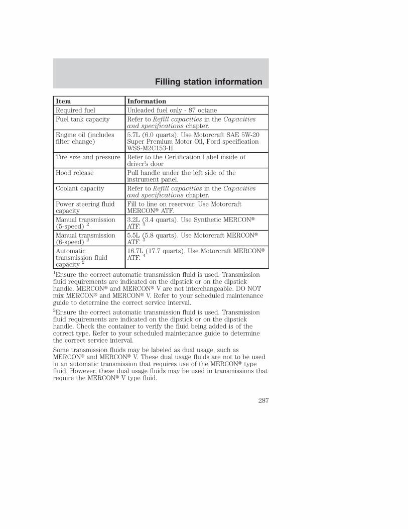
Item Information
Required fuel Unleaded fuel only - 87 octaneFuel tank capacity Refer to Refill capacities in the Capacities
and specifications chapter.Engine oil (includesfilter change)
5.7L (6.0 quarts). Use Motorcraft SAE 5W-20Super Premium Motor Oil, Ford specificationWSS-M2C153-H.
Tire size and pressure Refer to the Certification Label inside ofdriver’s door
Hood release Pull handle under the left side of theinstrument panel.
Coolant capacity Refer to Refill capacities in the Capacitiesand specifications chapter.
Power steering fluidcapacity
Fill to line on reservoir. Use MotorcraftMERCON� ATF.
Manual transmission(5-speed) 2
3.2L (3.4 quarts). Use Synthetic MERCON�ATF. 3
Manual transmission(6-speed) 2
5.5L (5.8 quarts). Use Motorcraft MERCON�ATF. 3
Automatictransmission fluidcapacity 2
16.7L (17.7 quarts). Use Motorcraft MERCON�ATF. 4
1Ensure the correct automatic transmission fluid is used. Transmissionfluid requirements are indicated on the dipstick or on the dipstickhandle. MERCON� and MERCON� V are not interchangeable. DO NOTmix MERCON� and MERCON� V. Refer to your scheduled maintenanceguide to determine the correct service interval.2Ensure the correct automatic transmission fluid is used. Transmissionfluid requirements are indicated on the dipstick or on the dipstickhandle. Check the container to verify the fluid being added is of thecorrect type. Refer to your scheduled maintenance guide to determinethe correct service interval.
Some transmission fluids may be labeled as dual usage, such asMERCON� and MERCON� V. These dual usage fluids are not to be usedin an automatic transmission that requires use of the MERCON� typefluid. However, these dual usage fluids may be used in transmissions thatrequire the MERCON� V type fluid.
Filling station information
287

MERCON� and MERCON� V type fluids are not interchangeable.DO NOT mix MERCON� and MERCON� V. Use of a transmissionfluid that indicates dual usage (MERCON� and MERCON� V) inan automatic transmission application requiring MERCON� maycause transmission damage. Use of any fluid other than therecommended fluid may cause transmission damage.3Service refill capacity is determined by filling the transmission to thebottom of the filler hole with the vehicle on a level surface.4Indicates only approximate dry-fill capacity. Some applications may varybased on cooler size and if equipped with in-tank cooler. The amount oftransmission fluid and fluid level should be set by the indication on thedipstick’s normal operating range.
Filling station information
288