Embed Size (px)
Citation preview

01. COMPANY PROFILE ------------------------ 03
02. STRAND POST TENSIONING SYSTEMS ------------------------------------------ 07
03. BAR POST TENSIONING SYSTEMS ------------------------------------------ 19
04. SYSTEM PROPERTIES AND DIMENSIONS --------------------------- 23
05. INSTALLATION -------------------------------- 37
06. INSTALLATION EQUIPMENT ------------------------------------- 41
07. EQUIPMENT PROPERTIES AND DIMENSIONS --------------------------- 47

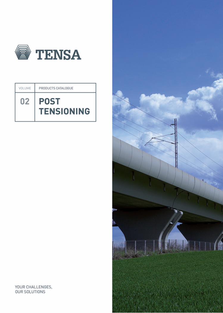
High Speed Train line from Milan to Naples, Cable stayed bridge over the river Po, Piacenza (Italy)

COMPANY PROFILE
Our mission is to constantly improve the methodsand the quality of construction processes
through research, innovation and cooperationwith designers, engineers and contractors worldwide.
01

04
TENSA
1951: Beginning of activity1964: In the sixties Tensacciai undergoes a phase of remark-able growth in Italy. Post-ten-sioning is just at the beginning of its history and its application is still experimental.1970: A programme of techno-logical renewal begins with the adoption of the steel strand.1980: Tensacciai develops new tensioning systems and equip-ment in the field of ground an-chors, combining innovation with versatility and ease of use.1990: New subsidiaries estab-lished in Brazil, India and Aus-tralia and in Europe sister com-panies in Portugal, Greece and the Netherlands.2000: The internationalization process of Tensacciai continues unabated.2010: The company becomes directly involved in projects in all five continents.2011: Tensacciai is acquired by Deal - world leading solutions provider in the field of bridge construction - and becomes part of De Eccher Group. Tensacciai is now member of an organisa-tion capable of designing, manu-facturing and installing systems everywhere in the world, thanks to specialised technicians, en-gineers in the technical depart-ment and quality control. All production and delivery process-es are attested by the ISO9001 certification.
2012: Tensacciai merges with Tesit, another successful con-crete specialist contractor with international experience in post-tensioning, steel bars, structural bearings and expan-sion joints becoming a promi-nent player in the field of spe-cialised subcontracting.Tensacciai enters into a World- wide Exclusive License Agree-ment with Rome-based TIS (Tecniche Idraulico-Stradali S.r.l.) - a leading company with ex-perience in designing and pro-ducing structural bearings, ex-pansion joints and anti-seismic devices since 1973.2014: TIS is acquired by Tensac-ciai.2015: TENSA is formed from the merging and development of the three important companies mentioned above: Tensacciai, Tesit, TIS.
HISTORY MISSION
Tensacciai, now renamed TENSA, was founded in 1951 with headquarters in Milan, Italy. It is now active in over 50 countries with a direct presence in 14 countries. TENSA is a leader in stay cables, post-tensioning, anti-seismic devices, structural bearings and expansion joints.TENSA has extensive references and numerous certifications for its products worldwide.
Our mission is to constantly improve the methods and the quality of construction process-es through research, innovation and cooperation with design-ers, engineers and contractors worldwide. A strong commit-ment to quality is the only way to ensure safe and long-last-ing structures. We support the design from the initial stage, challenging standards to devel-op custom solutions. We value timely execution and service as keys to building long-term rela-tionships.
Our core knowledge lies within stay-cables and post-tensioning systems, anti-seismic devices, structural bearings and expan-sion joints as well as all the related accessories, equipment and services.TENSA strives to push its vast experience towards new meth-ods and variations of appli-cations, developing ingenious solutions for building new structures, whether they are buildings or infrastructures, as well as the rehabilitation of ex-isting ones.
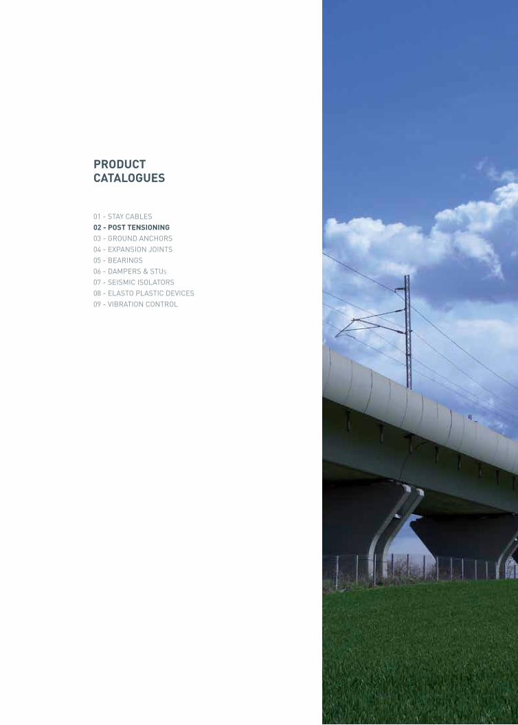
PRODUCT CATALOGUES
01 - STAY CABLES02 - POST TENSIONING03 - GROUND ANCHORS04 - EXPANSION JOINTS05 - BEARINGS06 - DAMPERS & STUs07 - SEISMIC ISOLATORS08 - ELASTO PLASTIC DEVICES09 - VIBRATION CONTROL
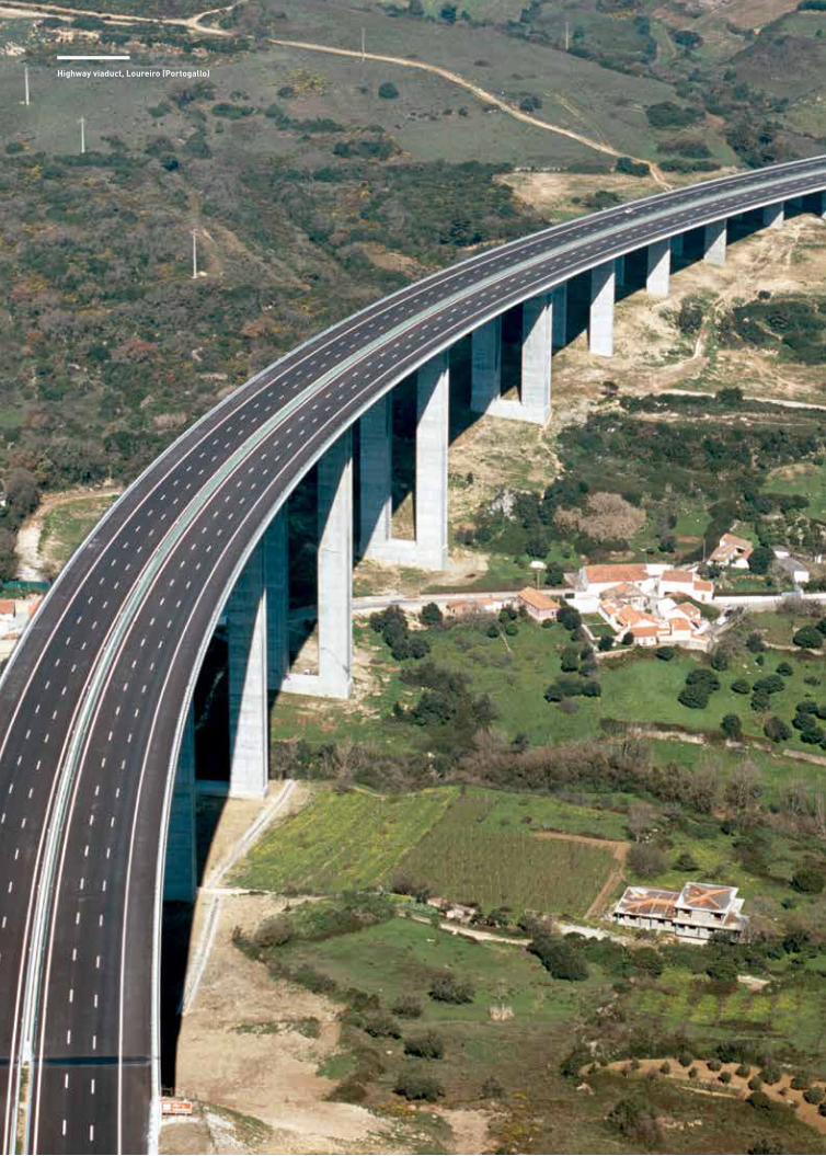
Highway viaduct, Loureiro (Portogallo)
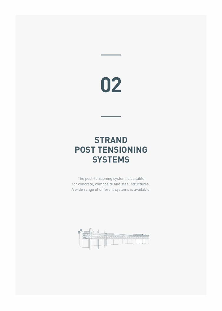
STRAND POST TENSIONING
SYSTEMS
The post-tensioning system is suitable for concrete, composite and steel structures. A wide range of different systems is available.
02
08
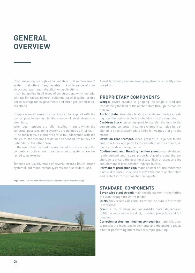
Post tensioning is a highly efficient structural reinforcement system that offers many benefits in a wide range of con-struction, repair and rehabilitation applications.It can be applied in all types of construction, which include, without limitation, general buildings, special slabs, bridge decks, storage tanks, pavements and other geotechnical ap-plications.
Compression stresses to concrete can be applied with the use of post tensioning tendons made of steel strands or steel bars.When such tendons are fully installed in ducts within the concrete, post tensioning systems are defined as internal. If the main tensile elements are in full adherence with the structure, the systems are defined as bonded, while they are unbonded in the other case.In the event that the tendons are placed in ducts outside the concrete structure, such post tensioning systems are re-ferred to as external.
Tendons are usually made of several strands (multi-strand systems), but mono-strand systems are also widely used.
GENERAL OVERVIEW
A post tensioning system employing strands is usually com-posed of:
PROPRIETARY COMPONENTSWedge: device capable of gripping the single strand and transferring the load to the anchor plate through the conical hole in it.Anchor plate: steel disk hosting strands and wedges, rest-ing over the cast-iron block embedded into the concrete.Cast-iron block: piece designed to transfer the load to the surrounding concrete. In some systems it can also be de-signed to directly accomodate holes for wedges that grip the strand.Deviation rear trumpet: when present, it is joined to the cast-iron block and permits the deviation of the entire bun-dle of strands entering the duct.Confinement and Bursting reinforcement: spiral-shaped reinforcement and rebars properly placed around the an-chorage to ensure the bearing of local high stresses and the containment of local tension-induced bursts.Permanent protection cap: made of steel or fibre reinforced plastic, if required, it is used to cover the entire anchor plate and protect it from atmospherical agents.
STANDARD COMPONENTSSeven wire steel strand: main tensile element transmitting the load through the entire tendon.Ducts: they create void conduits where the bundle of strands is threaded.Grout: a mix of water and cement-like materials required to fill the voids within the duct, providing protection and full bonding.Corrosion protection injection compounds: materials used to protect the main tensile elements and the anchorages as a better performing alternative to simple grouting.
High Speed Train line from Milan to Naples, Piacenza viaduct, Piacenza (Italy)

09
Post tensioning systems have been stringently tested un-der the requirements of the most important international legislation such as European Technical Approval Guideline ETAG013 and AASHTO LRFD Bridge Construction Specifica-tions.Through the process of testing and Approval Bodies evalua-tion, post tensioning systems have been granted European Technical Approvals ETA 08/0012 and 11/0007 and European Technical Assessment 15/0023.Systems are also provided with relevant Declarations of Per-formance (CE marking).Approval and Certification Bodies continuously monitor pro-duction and quality control activities carried out by TENSA over the post tensioning systems.
As a specialized contractor with decades of experience in its specific field, TENSA does not only provide supply and installation services of the finished products, but it is also capable of providing a wide range of associated services, starting with the design, moving on to the assembly and lab-oratory testing, including the definition of operating man-uals and installation procedures, and ending with the pro-vision of all engineering services related to the installation and maintenance throughout the life of the post-tensioned works. All this is carried out by TENSA’s own teams of spe-cialised and highly experienced technicians under a system that promotes full accountability and is in compliance with the standards of ISO9001.
QUALITY ANDCERTIFICATIONS
European Technical Approval No. ETA-11/0007 (English language translation, the original version is in French language)
Version of 22nd November 2011 Nom commercial Trade name
Procédé de précontrainte « TESIT 1C15 » monotoron “TESIT 1C15” monostrand post-tensioning system
Détenteur de l'ATE Holder of approval
DEAL S.r.l. Via Buttrio, Fraz. Cargnacco 33050 Pozzuolo del Friuli Udine - Italy
Type générique et utilisation prévue du produit de construction
Generic type and use of construction product
Kit de précontrainte monotoron de structures par post-tension Monostrand post-tensioning kit for bonded and unbonded internal prestressing of structures
Valid from: to:
22/11/2011 11/02/2016
Producteur du procédé Kit manufacturer
TENSACCIAI S.r.l. Via Venti Settembre 24 20123 Milano (Italy)
This version replaces the last version of 11st February 2011 with holder of approval :
FINEST S.p.A Via Venti Settembre 24 20123 Milano - Italy
Le présent agrément technique européen contient This European Technical Approval contains
35 pages comprenant 16 pages d'annexes (dessins) 35 pages including 16 pages of annexes (drawings)
Organisation pour l'Agrément Technique Européen European Organisation for Technical Approvals
Service d'études sur les transports, les routes et leurs aménagements 46 avenue Aristide Briand BP 100 92 225 BAGNEUX CEDEX Tel : + 33 (0)1 46 11 31 31 Fax : + 33 (0)1 46 11 31 69
MEMBRE DE L'EOTA
MEMBER OF EOTA

10
SYSTEM COMPONENTS
Post tensioning tendons are usually made of strands with a 15.7 mm (0.62”) or 15.2 mm (0.6”) diameter.
Dimensions and properties of 7-wire strands according to prEN 10138-3 (1)
STEEL DESIGNATION Y1860S7 Y1860S7
1860
15.2
139
1086
±2
259
306
228
3.5
2.5
4.5
195000
Tensile strength Rm (fpk) [MPa]
Diameter D [mm]
Cross sectional area Sn (Ap) [mm2]
Mass M [g/m]
Permitted deviation on nominal mass [%]
Characteristic value of maximum force Fm (Fpk) [kN]
Maximum value of maximum force Fm – max [kN]
Characteristic value of 0.1% proof force Fp0.1 (Fp0.1k) [kN]
Minimum elongation at maximum force Agt (L0 ≥ ) [%]
Relaxation after 1000 hours at 0.7 Fm (2) [%]
at 0.8 Fm (3) [%]
Modulus of elasticity E [MPa]
1860
15.7
150
1172
-
279
329
246
3.5
2.5
4.5
195000
(Notations according to prEN 10138-3, in rounded brackets to ETAG013 where possible)Other types of strands are available on request, according to main international standards.(1) Until prEN 10138-3 remains a draft norm, standards and regulations valid at the place of installation can be used.(2) The requirement for 70% Fm is mandatory.(3) Values for 80% Fm may be agreed between supplier and purchaser.
Tendons can also be made of 12.7 mm (0.5”) diameter strands: this system is less used but remains available in TENSA’s product range.
STEEL STRAND
11
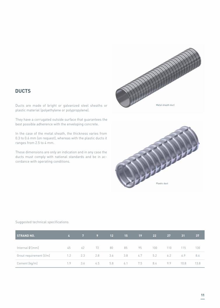
Ducts are made of bright or galvanized steel sheaths or plastic material (polyethylene or polypropylene).
They have a corrugated outside surface that guarantees the best possible adherence with the enveloping concrete.
In the case of the metal sheath, the thickness varies from 0.3 to 0.6 mm (on request), whereas with the plastic ducts it ranges from 2.5 to 4 mm.
These dimensions are only an indication and in any case the ducts must comply with national standards and be in ac-cordance with operating conditions.
STRAND NO. 4
Internal Ø [mm]
Grout requirement [l/m]
Cement [kg/m]
45
1.2
1.9
62
2.3
3.6
72
2.8
4.5
80
3.6
5.8
85
3.8
6.1
95
4.7
7.5
100
5.2
8.4
110
6.2
9.9
115
6.9
10.8
130
8.6
13.8
Plastic duct
Metal sheath duct
Suggested technical specifications
7 9 12 15 19 22 27 31 37
DUCTS

12
MULTI STRAND POST TENSIONING SYSTEMS
Multi-strands systems are provided with a wide range of anchorages and solutions for different construction needs.They can be used in concrete and composite structures, both for new constructions and the rehabilitation of existing structures where an increase in resistance is required.
INTERNAL MTAI LIVE ANCHORAGE The live anchorage MTAI is the most used and widely spread type of anchorage, whose compact geometry and reduced deviation angle provides a competitive advantage in all pro-ject applications, combined with high performance stand-ards and ease of installation. It can be also used in the un-bonded MTAIU version, where single sheathed strands are used.
INTERNAL MTAIM DEAD ANCHORAGE It is a non-accessible (dead) anchorage which is used in case accessibility during the stressing phases is not allowed.In such a case strands are placed before pouring the con-crete of the structure.
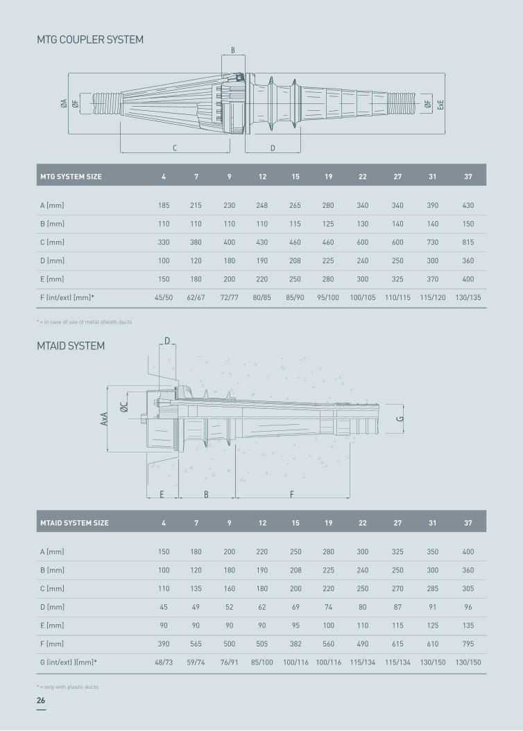
MTG COUPLER ANCHORAGEMTG system is the type of anchorage suitable for the cou-pling of tendons.It is fully integrated with the MTAI system and allows instal-lation of a secondary tendon after the primary one has been completely installed.

13
MTAID ELECTRICALLY INSULATED ANCHORAGEMTAID anchorage for electrically insulated post tensioning is designed to meet the demand for a total and permanent protection of post tensioning tendons from corrosive agents.This protection is granted by the tendon’s complete envelop-ment, which is made of:•MTAID anchorage with anchor plate separated from the cast-iron block by means of rigid dielectric disks, plastic connectors positioned inside the cast-iron block and con-nected to the corrugated ducts by means of tight joint seals:• full covering plastic protection cap• plastic ducts in the free length
The electrically insulated post tensioning system offers meas-urable advantages:• electrical insulation of the cable from the surrounding environment and consequent protection against corrosion caused by electrochemical phenomena, oxidation and chlo-rides attack;• possibility of controlling the protection’s integrity through electrical resistance measures during the structures’s life-time.
This system has been widely used and tested in the world’s largest full scale application of its kind, the 4.3 km long Pia-cenza viaduct (Italy).This system is in compliance with class PL-3 requirements of PTI/ASBI M50.3-12 “Guide Specification for Grouted Post-tensioning”.
MTRN ADJUSTABLE ANCHORAGEThis anchorage has the great advantage of allowing the ad-justment to force at any time, depending on the structure’s behaviour and the project’s construction requirements.It also gives the possibility of monitoring loads, especially in the first period after the installation of cables, when either the strands relaxation or the viscous effects of concrete can affect the acting forces.MTRN anchorages are made of a threaded anchorage with a nut, all protected with a cap filled with grease.The load adjustment operation is carried out with a special ring jack, especially designed for these applications.This system can be also provided in a fully replaceable ver-sion and also with a monitoring system, with load cells and data recording system.
PTSE FLAT ANCHORAGEThe new improved system for thin slabs post tensioning is the PTSE, whose compact size is the best performing in the market.Range is from 2 up to 5 strands and can be used as a bonded system with plastic / metal ducts or unbonded with plastic coated strands.
14
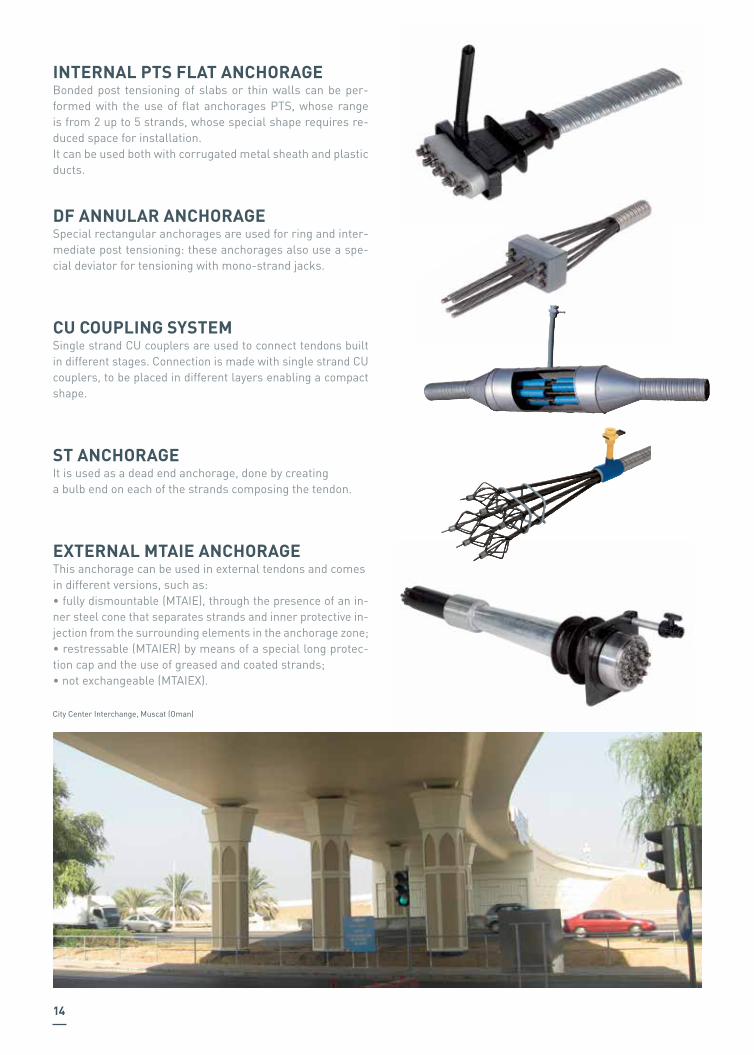
INTERNAL PTS FLAT ANCHORAGEBonded post tensioning of slabs or thin walls can be per-formed with the use of flat anchorages PTS, whose range is from 2 up to 5 strands, whose special shape requires re-duced space for installation.It can be used both with corrugated metal sheath and plastic ducts.
DF ANNULAR ANCHORAGESpecial rectangular anchorages are used for ring and inter-mediate post tensioning: these anchorages also use a spe-cial deviator for tensioning with mono-strand jacks.
CU COUPLING SYSTEMSingle strand CU couplers are used to connect tendons built in different stages. Connection is made with single strand CU couplers, to be placed in different layers enabling a compact shape.
ST ANCHORAGEIt is used as a dead end anchorage, done by creating a bulb end on each of the strands composing the tendon.
EXTERNAL MTAIE ANCHORAGEThis anchorage can be used in external tendons and comes in different versions, such as:• fully dismountable (MTAIE), through the presence of an in-ner steel cone that separates strands and inner protective in-jection from the surrounding elements in the anchorage zone;• restressable (MTAIER) by means of a special long protec-tion cap and the use of greased and coated strands;• not exchangeable (MTAIEX).
City Center Interchange, Muscat (Oman)
15
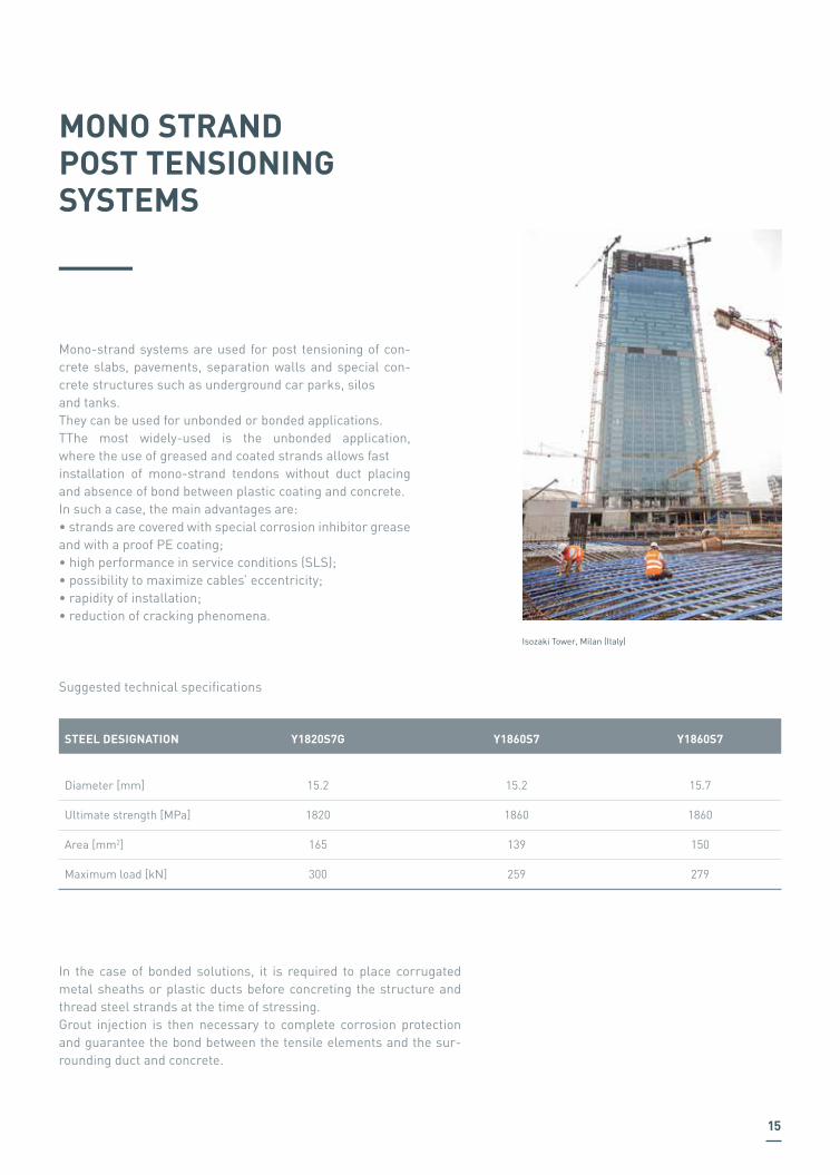
Mono-strand systems are used for post tensioning of con-crete slabs, pavements, separation walls and special con-crete structures such as underground car parks, silos and tanks.They can be used for unbonded or bonded applications.TThe most widely-used is the unbonded application, where the use of greased and coated strands allows fast installation of mono-strand tendons without duct placing and absence of bond between plastic coating and concrete.In such a case, the main advantages are:• strands are covered with special corrosion inhibitor grease and with a proof PE coating;• high performance in service conditions (SLS);• possibility to maximize cables’ eccentricity;• rapidity of installation;• reduction of cracking phenomena.
MONO STRAND POST TENSIONING SYSTEMS
STEEL DESIGNATION Y1820S7G Y1860S7 Y1860S7
Diameter [mm]
Ultimate strength [MPa]
Area [mm2]
Maximum load [kN]
15.2
1820
165
300
15.2
1860
139
259
15.7
1860
150
279
Suggested technical specifications
In the case of bonded solutions, it is required to place corrugated metal sheaths or plastic ducts before concreting the structure and thread steel strands at the time of stressing.Grout injection is then necessary to complete corrosion protection and guarantee the bond between the tensile elements and the sur-rounding duct and concrete.
Isozaki Tower, Milan (Italy)

16
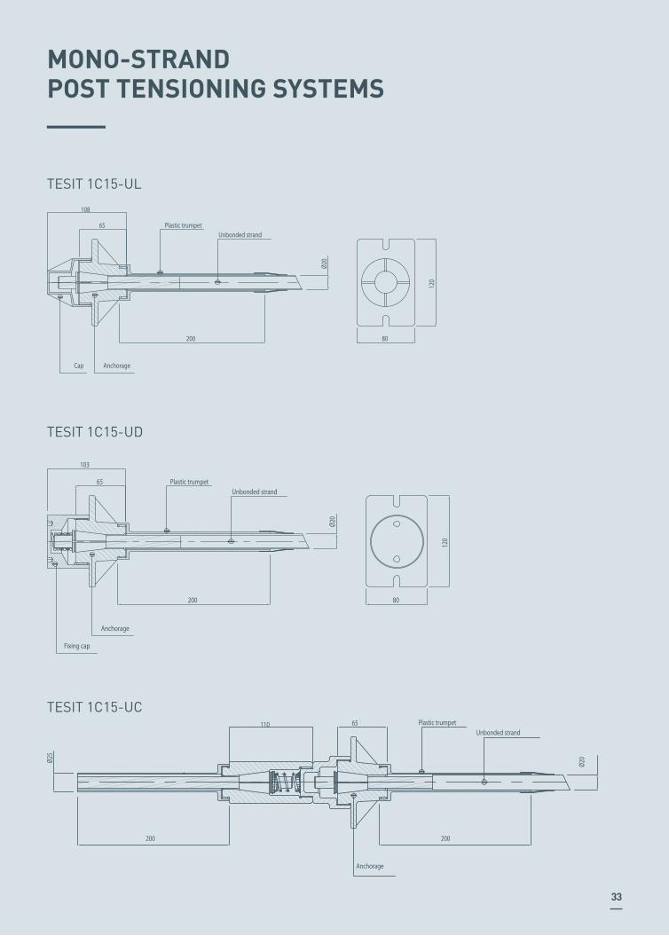
LIVE END TESIT 1C15 UL/BLThis anchorage is made of a single cast-iron piece which transfers the load from the tensile element to the concrete and hosts the wedge that grips the strand.It is available either in the unbonded version 1C15UL or in the bonded 1C15BL, both complete with covering caps.
DEAD END TESIT 1C15 UD/BDIt is used where anchorage is not accessible for stressing operations.It can be provided both in the unbonded version 1C15UD or in the bonded 1C15BD version, complete with their relevant wedge spring and fixing cap.
COUPLER TESIT 1C15 UC/BCThis system allows direct mechanical coupling of tendons that have been placed during different construction phases.
Regione Piemonte Tower, Turin (Italy)
Isozaki Tower, Milan (Italy)

BAR POST TENSIONINGSYSTEMS
Threaded steel bars can be used in different applications and structures, providing safe and reliable application of post tensioning.
03

20
TENSA supplies bars with continuous thread for post tensioning applications in buildings, roads, bridges and viaducts, tunnels and mine shafts.These systems can be provided in diameters varying from 12 to 75 mm, and are used worldwide in post tensioning and in pre-tensioning systems applications.The advantages of using these post tensioning systems are several and are supported by excellent results achieved on various project sites.Different corrosion protection systems and steel grades are available.
The main advantages are:• Easy handling on-site;• Continuous thread along the entire length of the bar, which ensures optimal adhesion to the cast in situ concrete;• Cut to size and possibility of extension using couplers in any position of the bar;
BAR POST TENSIONINGSYSTEMS
• Different possibilities for protection against corrosive phe-nomena: galvanized, hot dip galvanized, epoxy coated, paint-ed in accordance to different standards .
For special applications further steel grades are available.
Arch Bridge over the Railway in Souk Ahras (Algeria)

STEEL BARCHARACTERISTICS
CONTINUOUS LEFT HAND, THREADED BAR, HOT ROLLED AND RIBBED
21
Several types of accessories are available to meet all de-sign requirements. Full range of couplers, nuts and anchor plates, including special pieces can be provided on request. TENSA is able to provide a wide range of product customi-zation, for applications requiring new and different shapes.
End caps are always placed when it is necessary to provide a protective injection in the anchorage zone.
Bars can be provided with different corrosion protections such as spray galvanization, hot galvanization or epoxy coating.
(1) A10 = ultimate elongation in a gauge length to 10 bar diameters
CONTINUOUS THREAD BARS RIGHT HAND, HOT ROLLED
670 N/mm² / 800 N/mm² / ≥ 5%
SAS 670/800
18d [mm]
max dA [mm]
fyk / ftk / Agt
Fyk (F0.2k) [kN]
Ftk [kN]
A [mm2]
21
170
204
254
25
255
304
380
26
329
393
491
32
413
493
616
34
474
565
707
40
645
770
962
48
973
1162
1452
63
1740
2077
2597
70
2122
2534
3167
82
2960
3535
4418
22 25 28 30 35 43 57.5 63.5 75
950 N/mm² / 1050 N/mm² / ≥ 7 % 835 N/mm² / 1035 N/mm² / ≥ 7%
SAS 950/1050SAS 835/1050
18d [mm]
max dA [mm]
fp0.1k / fpk / A10 (1)
Fyk (F0.1k) [kN]
Fpk [kN]
A [mm2]
21
230
255
241
31
525
580
551
37
760
845
804
42
960
1070
1020
46
1190
1320
1257
53
1650
1820
1735
64
2155
2671
2581
72
2780
3447
3331
82
3690
4572
4418
26.5 32 36 40 47 57 65 75
22
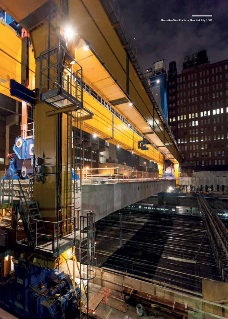
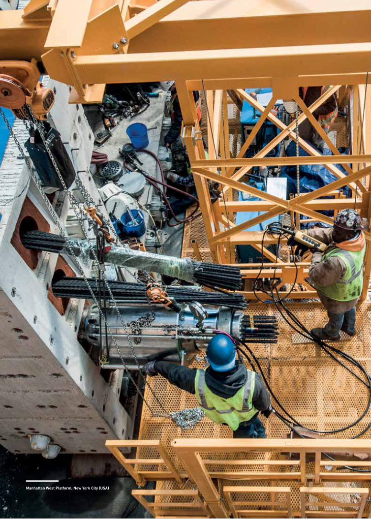
Manhattan West Platform, New York City (USA)

SYSTEM PROPERTIESAND DIMENSIONS
An overlook of all the properties and dimensions
listed in tables for each system.
04
24
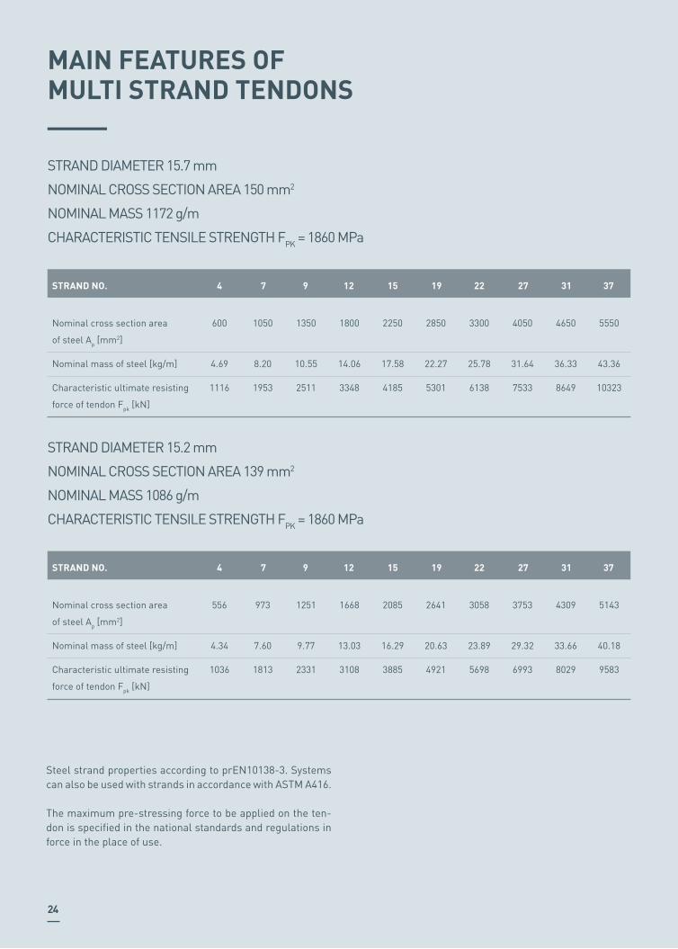
MAIN FEATURES OFMULTI STRAND TENDONS
STRAND DIAMETER 15.7 mm
NOMINAL CROSS SECTION AREA 150 mm2
NOMINAL MASS 1172 g/m
CHARACTERISTIC TENSILE STRENGTH FPK = 1860 MPa
STRAND DIAMETER 15.2 mm
NOMINAL CROSS SECTION AREA 139 mm2
NOMINAL MASS 1086 g/m
CHARACTERISTIC TENSILE STRENGTH FPK = 1860 MPa
Steel strand properties according to prEN10138-3. Systems can also be used with strands in accordance with ASTM A416.
The maximum pre-stressing force to be applied on the ten-don is specified in the national standards and regulations in force in the place of use.
STRAND NO. 4
Nominal cross section area
of steel Ap [mm2]
Nominal mass of steel [kg/m]
Characteristic ultimate resisting
force of tendon Fpk [kN]
600
4.69
1116
1050
8.20
1953
1350
10.55
2511
1800
14.06
3348
2250
17.58
4185
2850
22.27
5301
3300
25.78
6138
4050
31.64
7533
4650
36.33
8649
5550
43.36
10323
7 9 12 15 19 22 27 31 37
STRAND NO. 4
Nominal cross section area
of steel Ap [mm2]
Nominal mass of steel [kg/m]
Characteristic ultimate resisting
force of tendon Fpk [kN]
556
4.34
1036
973
7.60
1813
1251
9.77
2331
1668
13.03
3108
2085
16.29
3885
2641
20.63
4921
3058
23.89
5698
3753
29.32
6993
4309
33.66
8029
5143
40.18
9583
7 9 12 15 19 22 27 31 37
25
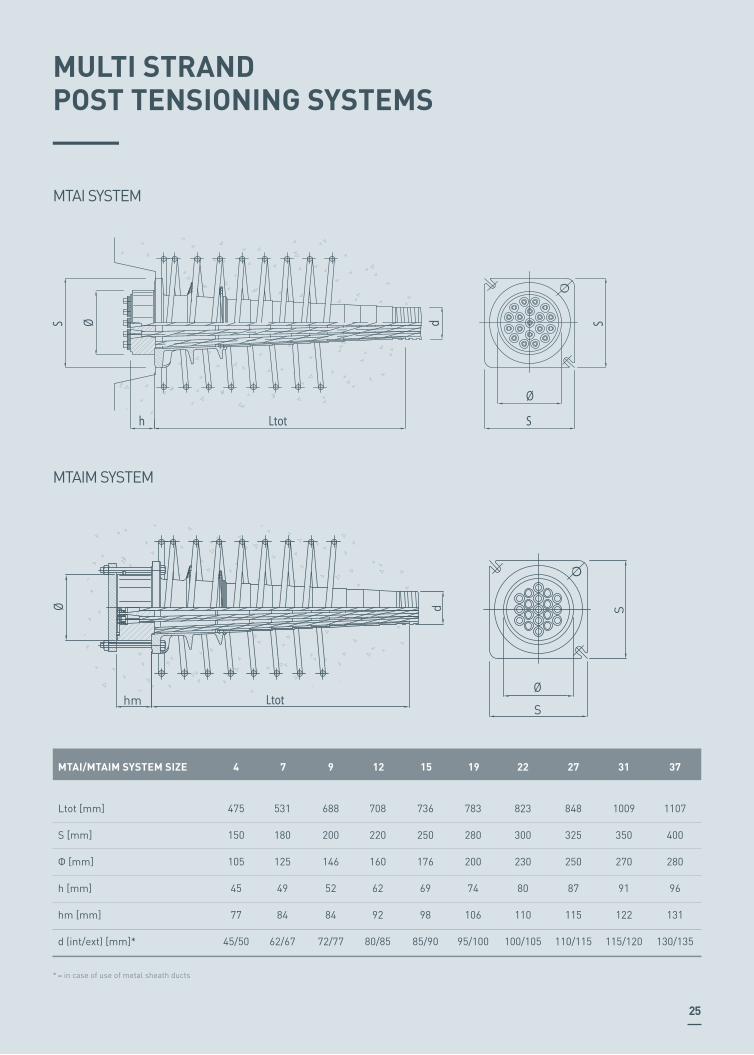
MULTI STRANDPOST TENSIONING SYSTEMS
MTAI SYSTEM
MTAIM SYSTEM
S
Ltothd S
S
Ø
Ø
MTAI/MTAIM SYSTEM SIZE
Ltot [mm]
S [mm]
Φ [mm]
h [mm]
hm [mm]
d (int/ext) [mm]*
4
475
150
105
45
77
45/50
531
180
125
49
84
62/67
7
688
200
146
52
84
72/77
9
708
220
160
62
92
80/85
12
736
250
176
69
98
85/90
15
783
280
200
74
106
95/100
19
823
300
230
80
110
100/105
22
848
325
250
87
115
110/115
27
1009
350
270
91
122
115/120
31
1107
400
280
96
131
130/135
37
Ø
Ø
Ltot
d
hm
S
S
* = in case of use of metal sheath ducts
E B F
G
D
ØC
AxA
C
ØFØA
D
ØF ExE
BMTG COUPLER SYSTEM
MTAID SYSTEM
MTG SYSTEM SIZE
A [mm]
B [mm]
C [mm]
D [mm]
E [mm]
F (int/ext) [mm]*
4
185
110
330
100
150
45/50
215
110
380
120
180
62/67
7
230
110
400
180
200
72/77
9
248
110
430
190
220
80/85
12
265
115
460
208
250
85/90
15
280
125
460
225
280
95/100
19
340
130
600
240
300
100/105
22
340
140
600
250
325
110/115
27
390
140
730
300
370
115/120
31
430
150
815
360
400
130/135
37
26
MTAID SYSTEM SIZE
A [mm]
B [mm]
C [mm]
D [mm]
E [mm]
F [mm]
G (int/ext) )[mm]*
4
150
100
110
45
90
390
48/73
180
120
135
49
90
565
59/74
7
200
180
160
52
90
500
76/91
9
220
190
180
62
90
505
85/100
12
250
208
200
69
95
382
100/116
15
280
225
220
74
100
560
100/116
19
300
240
250
80
110
490
115/134
22
325
250
270
87
115
615
115/134
27
350
300
285
91
125
610
130/150
31
400
360
305
96
135
795
130/150
37
* = only with plastic ducts
* = in case of use of metal sheath ducts

27
MTAIE SYSTEM
MTAI SYSTEM SIZE
A [mm]
B [mm]
C [mm]
D [mm] / thickness [mm]*
E [mm]
F [mm]
4
150
100
135
63/3.6
310
80
180
120
160
75/4.5
360
102
7
200
180
177
90/5.4
430
120
9
220
190
195
110/6.6
450
140
12
250
208
210
110/6.6
520
145
15
280
225
245
125/7.4
600
159
19
300
240
265
125/7.4
660
193.7
22
325
250
295
140/8.3
700
193.7
27
350
300
330
160/9.5
750
219
31
400
380
330
160/9.5
800
229
37
B Variable
E
ØD ØFAxA
ØC
* = with use of smooth plastic ducts
28
SS
SS
SL
ØS
dØrb
p Øb
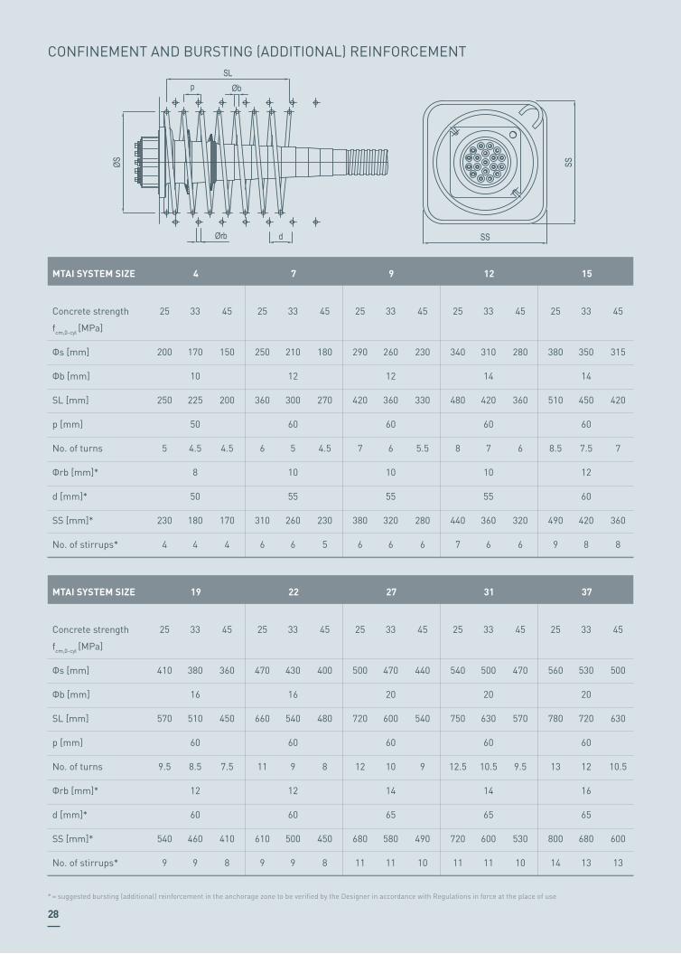
CONFINEMENT AND BURSTING (ADDITIONAL) REINFORCEMENT
MTAI SYSTEM SIZE
Concrete strength
fcm,0-cyl [MPa]
Φs [mm]
Φb [mm]
SL [mm]
p [mm]
No. of turns
Φrb [mm]*
d [mm]*
SS [mm]*
No. of stirrups*
25
200
250
5
230
4
33
170
10
225
50
4.5
8
50
180
4
4
45
150
200
4.5
170
4
25
250
360
6
310
6
33
210
12
300
60
5
10
55
260
6
7
45
180
270
4.5
230
5
25
290
420
7
380
6
33
260
12
360
60
6
10
55
320
6
9
45
230
330
5.5
280
6
25
340
480
8
440
7
33
310
14
420
60
7
10
55
360
6
12
45
280
360
6
320
6
25
380
510
8.5
490
9
33
350
14
450
60
7.5
12
60
420
8
15
45
315
420
7
360
8
MTAI SYSTEM SIZE
Concrete strength
fcm,0-cyl [MPa]
Φs [mm]
Φb [mm]
SL [mm]
p [mm]
No. of turns
Φrb [mm]*
d [mm]*
SS [mm]*
No. of stirrups*
25
410
570
9.5
540
9
33
380
16
510
60
8.5
12
60
460
9
19
45
360
450
7.5
410
8
25
470
660
11
610
9
33
430
16
540
60
9
12
60
500
9
22
45
400
480
8
450
8
25
500
720
12
680
11
33
470
20
600
60
10
14
65
580
11
27
45
440
540
9
490
10
25
540
750
12.5
720
11
33
500
20
630
60
10.5
14
65
600
11
31
45
470
570
9.5
530
10
25
560
780
13
800
14
33
530
20
720
60
12
16
65
680
13
37
45
500
630
10.5
600
13
* = suggested bursting (additional) reinforcement in the anchorage zone to be verified by the Designer in accordance with Regulations in force at the place of use

29
CENTRE AND EDGE DISTANCE
C'A
BA
C'AAC' C' C' A B A C' C'A
BA
C'
C’ – concrete cover in accordance with European Standard
EN 1992-1-1 and national regulations valid at the place of use
MTAI SYSTEM SIZE
fcm,0 - cyl = 25 MPa
fcm,0 - cyl = 33 MPa
fcm,0 - cyl = 45 MPa
fcm,0 - cyl = 25 MPa
fcm,0 - cyl = 33 MPa
fcm,0 - cyl = 45 MPa
4
125
110
95
270
240
210
165
145
130
355
315
280
7
190
165
144
400
355
315
9
220
195
170
465
410
360
12
250
220
190
520
460
405
15
280
245
215
580
515
450
19
305
265
230
630
555
485
22
340
300
260
700
620
540
27
365
325
280
755
670
585
31
410
360
310
840
740
640
37
Minimum edge distance (A) [mm] not including cover
Minimum centre distance (B) [mm]

30
PTSE SYSTEM
PTSE SYSTEM SIZE
LTOT [mm]
S1 [mm]
S2 [mm]
S3 [mm]
A [mm]
B [mm]
h [mm]
Lt [mm]
a x b (int) metal sheet [mm]
a x b (int) plastic [mm]
24
115
75
150
88
67
47
240
42 / 18
38 / 22
2
344
150
95
175
123
87
47
300
69 / 18
72 / 21
4
374
185
95
190
150
87
47
330
86 / 18
90 / 21
5
CONFINEMENT REINFORCEMENT
PTSE SYSTEM SIZE
Concrete strength fcm,0 – cyl [MPa]
Φb [mm]
SA [mm]
SB [mm]
SL [mm]
Pb [mm]
No. of stirrups
20
12
135
120
180
45
5
2
20
16
200
140
300
50
7
4
20
16
235
160
350
50
8
5
INTERAXIS AND EDGE DISTANCES
PTSE SYSTEM SIZE
Tested block dimensions a
Tested block dimensions b
Minimum slab thickness
220
160
140
2
340
195
165
4
380
220
190
5
The actual spacing / centre distance and edge distance in the structure shall comply with:
Ac = x · y ≥ a · b
x ≥ 0.85 · a
y ≥ 0.85 · b
x’ ≥ 0.5 · x
y’ ≥ 0.5 · y
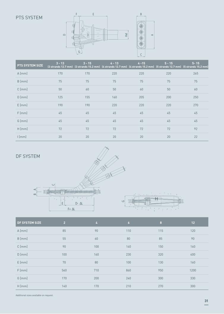
DF SYSTEM
Additional sizes available on request.
DF SYSTEM SIZE
A [mm]
B [mm]
C [mm]
D [mm]
E [mm]
F [mm]
G [mm]
H [mm]
85
55
90
100
70
560
170
140
2
90
60
100
160
80
710
200
170
4
110
80
140
230
100
860
240
210
6
115
85
150
320
130
950
300
270
8
120
90
160
400
160
1200
330
300
12
31
PTS SYSTEM
C
HxI
G
D
BEF
ATESIT
PTS SYSTEM SIZE
A [mm]
B [mm]
C [mm]
D [mm]
E [mm]
F [mm]
G [mm]
H [mm]
I [mm]
170
75
50
125
190
45
45
72
20
3 - 13(3 strands 12.7 mm)
170
75
60
155
190
45
45
72
20
3 - 15(3 strands 15.2 mm)
220
75
50
160
220
45
45
72
20
4 - 13(4 strands 12.7 mm)
220
75
60
205
220
45
45
72
20
4 -15(4 strands 15.2 mm)
220
75
50
200
220
45
45
72
20
5 - 15(5 strands 12.7 mm)
265
75
60
250
270
45
45
92
22
5- 15(5 strands 15.2 mm)
H
HG
AB
F+ L
E D- L
C

ST DEAD END SYSTEM
H ØE
ØI
G
C
D
A
B
F
Option 1 Option 2
ST SYSTEM SIZE
A [mm]
B [mm]
C [mm]
D [mm]
E [mm]
F [mm]
G [mm]
H [mm]
I [mm]
-
210
80
80
10
50
250
800
100
4
80
240
-
-
10
50
350
800
100
7
-
-
160
160
12
60
400
800
150
9
80
400
160
160
14
60
400
800
150
12
-
-
240
240
14
60
400
900
220
19
-
-
160
160
14
60
400
800
150
15
32
I
D+ I
E+ I
F+ I
ØC ØB
CU COUPLING SYSTEM
CU SYSTEM SIZE
A [mm]
B [mm]
C [mm]
D [mm]
E [mm]
F [mm]
675
45/50
140
300
-
-
4T15
800
62/67
159
340
-
-
7T15
950
72/77
177
400
800
-
9T15
1250
80/85
193
400
800
1200
12T15
1700
110/115
244
400
600
1400
27T15
1250
85/90
193
400
800
1200
15T15
1300
95/100
193
400
800
1200
19T15
1385
100/105
219
400
800
1800
22T15
65
200
Ø20
AnchorageCap
80
120
108
Plastic trumpetUnbonded strand
103
65
200
Ø20
Anchorage
Fixing cap
80
120
Unbonded strandPlastic trumpet
65
200
Ø20
Anchorage
110
200
Ø25
Plastic trumpetUnbonded strand
MONO-STRAND POST TENSIONING SYSTEMS
TESIT 1C15-UL
TESIT 1C15-UD
TESIT 1C15-UC
33

CONFINEMENT REINFORCEMENT
CENTRE AND EDGE DISTANCES
Values valid for fcm,0 – cyl ≥ 16.5 MPa
c = concrete cover in accordance with European Standard EN 1992-1-1 and national regulations currently in force applicable in the country of utilisation
44
8
120
80
140
60 +
C
80 + C 180
34
35
FRICTION LOSSES
The calculation of the loss of pre-stressing force due to fric-tion and wobble effects inside tendons is usually made start-ing from the following equation (source: EN 1992-1-1):
BASIC ELONGATION EVALUATION FACTORS
CALCULATIONNOTES
where: ΔPµ (x) = loss of pre-stressing force from 0 up to x distance [kN] x = distance from the stressing point [m] Pmax = force at the stressing end [kN] µ = friction coefficient between strands and ducts [1/rad] θ = sum of the angular deviation from 0 up to x distance, irrespective of direction or sign [rad] k = non-intentional angular deviation inside tendons, wobble coefficient [rad/m]
Values for friction coefficient µ are between 0.18 and 0.22 while k values are between 0.005 and 0.01.
Recommended values for calculation are µ = 0.19 [1/rad] and k = 0.005 [rad/m].
The elongation of the tendon, under the action of one or two jacks, is determined by the designer and verified at the con-struction site. The elongation calculation must clearly spec-ify the theoretical elongation calculation and the corrective elements taken into account. It must be possible to estab-lish with great accuracy the relationship between calculat-ed elongation and measured elongation. In fact, secondary terms should be added to the elongation of the tendon along its length up to the anchorages, to obtain the real elongation. Real elongation measured at the construction site is thus defined as the sum of the following elements:
ΔLo = ΔLa + ΔLb + ΔLr + ΔLv
ΔPµ (x) = Pmax (1-e-µ(θ+kx))
• ΔLa: theoretical elongation of the strand, calculated on the basis of the length between the anchorages, at one or two ends, depending on whether one or two jacks are used.• ΔLb: concrete elastic shortening. This piece of data, since it is extremely small, is usually disregarded.• ΔLr: accumulation of deformations of the anchorage devic-es, for the deflection of the anchorages into the concrete and for the draw-in of the wedges.• ΔLv: draw-in of the strand wedges within the jack and jack deformations.

Jamal Abdul Nasser Street, Kuwait City (Kuwait)
INSTALLATION
Our teams take care of all installation phases, thanks to a decades-long experience in the filed
and dedicated working procedures.
05

38
The installation of TENSA’s post tensioning systems consists of the following phases:
PLACING OF THE DUCTS AND ANCHORAGE BODY For internal post tensioning, ducts are placed before con-creting, fixed to the reinforcing steel of the structure to avoid that their position changes during the pouring phase. For longitudinal post tensioning they are usually placed fol-lowing a parabolic layout. Anchorage bodies are securely fastened to the formwork.
THREADING OF STRANDS Strands are threaded one by one inside the placed duct, us-ing special strand pushing machines. Threading operations are carried out with care to avoid any damage to the strand or to the duct.
TENSIONING Stressing is carried out using multi-strand or mono-strand jacks, depending on the system used and local jobsite condi-tions, all provided with automatic hydraulic lock-off system.
GROUTING Grouting of tendons is performed to protect strands from corrosion and can be performed either with cement grout or soft anti-corrosion compounds. Tendons’ ducts are provided with air vent pipes at the high-est points to ensure absence of vacuum pockets and must be completely tight. In case of a complex tendon layout or special applications, vacuum injection may be performed through the use of dedicated equipment.
Together with its post tensioning system TENSA has devel-oped a range of dedicated installation equipment, including multi and mono stressing jacks, hydraulic pumps, grouting pumps and load cells. Nowadays TENSA is proudly involved in the design and pro-duction of new stressing jacks, applying technology and ex-perience to achieve higher performing results.
INSTALLATION PHASES
Sa Carneiro Airport, Porto (Portugal)
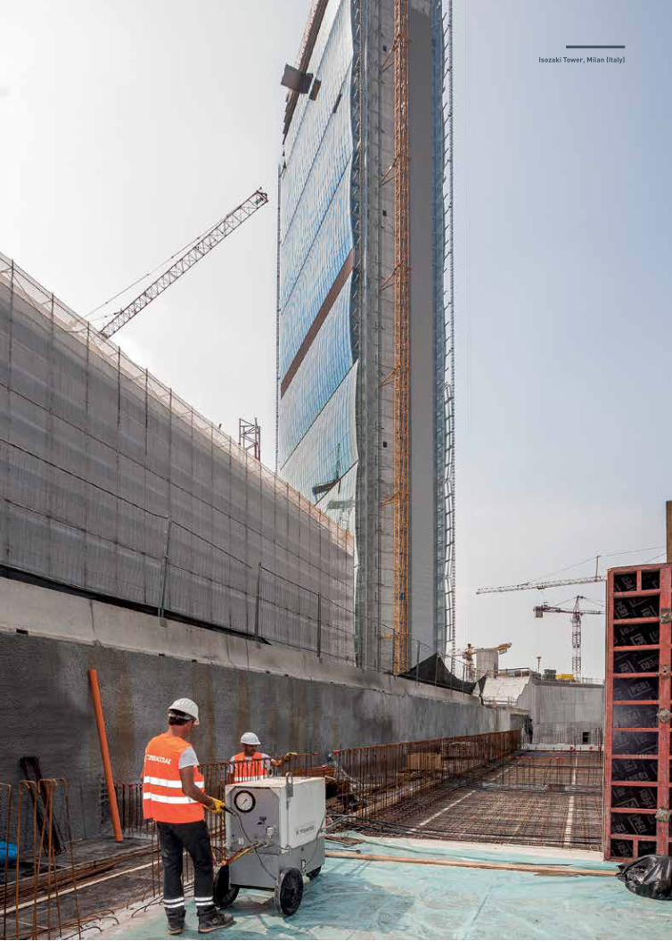
Isozaki Tower, Milan (Italy)
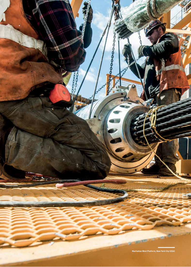
Manhattan West Platform, New York City (USA)
INSTALLATIONEQUIPMENT
A wide range of equipment for tendons installation that ensures a complete and safe work.
06

42
MULTI-STRAND AND MONO-STRAND JACKS
TENSA manufactures several types of “MT” stressing jacks (mono-group), ranging from 1000 up to 10000 kN. They have been designed and built considering the following stressing needs: minimum strand waste (300 mm to 500 mm), automatic lock-off, easy removal and control of the wedges, jack rotation around its own axis.
MT SERIESThe “MT” jacks have been designed and built by TENSA con-sidering the following stressing needs: minimum strand waste, jack built-in hydraulic circuit, controlled lock-off, easily removed and controlled wedges, jack rotation around its own axis, making it easier to place and wedge onto the tendon. The high functionality and high quality of the material have made this line of jacks very successful under the most se-vere operating conditions.
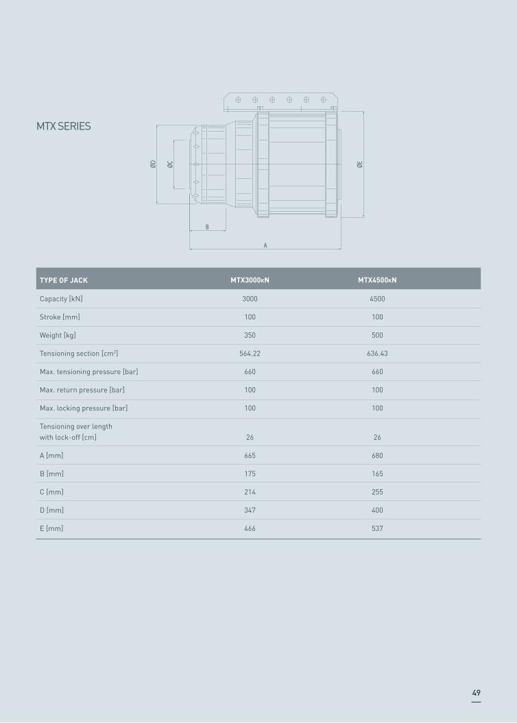
MTX SERIESThe “MTX” series jacks, as natural evolution of the “MT” se-ries jack, have been designed and built for stressing in very confined areas, where the overall dimensions of the jack are a fundamental factor.
MTP SERIESMTP series jacks are the latest evolution of TENSA’s stress-ing equipment. This series has been designed bearing in mind all the lessons learnt from many years of experience on project sites all around the world, and is designed to guarantee top performance during installation.
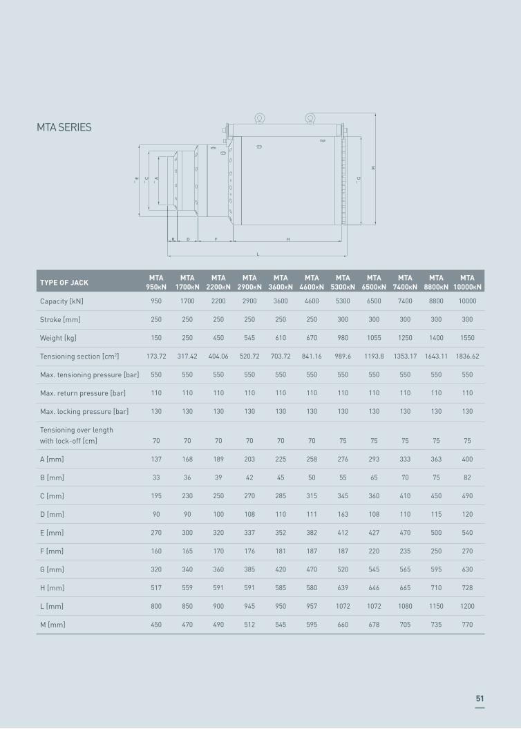
MTA SERIESMTA series jacks are the latest development of TENSA’s multi-strand jacks, designed with front end master wedges gripping and short strands overlength needed. Sizes and weights are combined to provide a good balance between performance and site needs. Jacks are completed as usual with automatic lock-off system and easy transport and movement connections.

43
STRESSING PUMP TENSA offers a wide range of hydraulic pumps, which differ in terms of performance ratings, dimensions and weight. The “PT” series jacks require stressing pumps with power ratings ranging between 2.2 and 10 kW. The MT, MTX and MTP series jacks require stressing pumps with power ratings ranging between 7.5 and 30 kW. All TENSA pumps are equipped with an automatic lock-off circuit.
PT SERIES (MONO-STRAND)TENSA manufactures four types of mono-strand “PT” series jacks, which differ in terms of tensioning section, weight and dimensions. All jacks of the “PT” series are equipped with the automatic lock-off system.
GROUTING PUMP The “GP” pump is available in various models, which differ in terms of performance ratings. The grouting pump consists of an eccentric screw pump, a mixer and a turbomixer. All the machines are equipped with a push-button control panel.
VACUUM PUMPTENSA offers vacuum pumps with power ratings ranging from 4 kW to 7.5 kW. This pump is used to inject grout under a vacuum, thus guaranteeing perfect grouting without any immission of air.

44
EXTRUSION JACK The equipment consists of a high powered portable jack (XG2), fed by a hydraulic pump. This jack extrudes passive anchorages (compression grips) at the ends of the strands. The jack drive will vary depending on the type of pump to which it is connected.
STRAND PUSHING MACHINE This equipment, designed to insert strands into the ducts, consists of a hydraulic pump and a unit able to push strands for long distances inside the conducts.The two units can be installed at a remote location.TENSA offers various models to meet all construction site requirements.
BOND END MACHINEThe equipment consists of an automatic pump XST/3” and an operating unit (jack UST/3”) that opens the strand.The bond end operation is completely automatic, controlled by an electronic device regulating the duration and the in-tensity of the force applied.
45
Manhattan West Platform, New York City (USA)

Covas Viaduct, Galizia (Spain)

EQUIPMENT PROPERTIESAND DIMENSIONS
An overlook of all the properties and dimensions listed for each equipment.
07

48
ØD ØC
B
A
ØE
Detailed technical sheets and instruction manuals are available on request.
MULTI-STRANDSTRESSING JACKS
MT SERIES
TYPE OF JACK
Capacity [kN]
Stroke [mm]
Weight [kg]
Tensioning section [cm2]
Max. tensioning pressure [bar]
Max. return pressure [bar]
Max. locking pressure [bar]
Tensioning over length with lock-off [cm]
A [mm]
B [mm]
C [mm]
D [mm]
E [mm]
1000
250
100
155.51
600
180
165
35
950
155
137
162
248
MT1000kN
1500
250
180
302.18
500
180
165
37
931
130
152
185
310
MT1500kN
2500
250
290
361.00
700
180
165
37
951
150
173
213
339
MT2500kN
3000
250
350
400.55
700
180
165
38
984
154
195
236
370
MT3000kN
3500
250
420
492.44
700
180
165
38
970
147
214
252
415
MT3500kN
4500
250
600
725.71
700
180
165
45
1107
200
243
310
512
MT4500kN
9000
150
1250
1625.00
700
180
165
52
1016
191
322
407
714
MT9000kN
6000
300
1000
879.60
700
180
165
51
1237
207
295
380
615
MT6000kN
49
MTX SERIES
ØD ØC
B
A
ØE
TYPE OF JACK
Capacity [kN]
Stroke [mm]
Weight [kg]
Tensioning section [cm2]
Max. tensioning pressure [bar]
Max. return pressure [bar]
Max. locking pressure [bar]
Tensioning over length with lock-off [cm]
A [mm]
B [mm]
C [mm]
D [mm]
E [mm]
3000
100
350
564.22
660
100
100
26
665
175
214
347
466
MTX3000kN
4500
100
500
636.43
660
100
100
26
680
165
255
400
537
MTX4500kN

50
B
A
ØD ØC ØE
MTP SERIES
TYPE OF JACK
Capacity [kN]
Stroke [mm]
Weight [kg]
Tensioning section [cm2]
Max. tensioning pressure [bar]
Tensioning over length with lock-off [cm]
A [mm]
B [mm]
C [mm]
D [mm]
E [mm]
850
150
106
194.78
500
85
493
217
136
146
230
MTP (MS)850kN
2600
250
290
549.78
550
80
880
195
227
270
375
MTP (MS)2600kN
4800
300
700
876.51
550
110
1185
195
290
330
470
MTP (MS)4800kN
6800
300
875
1237.01
550
115
1200
217
256
336
560
MTP (MS)6800kN
7000
295
1200
1258.00
550
115
1275
320
320
396
560
MTP (MS)7000kN
9750
300
1770
1772.45
550
115
1200
195
370
470
680
MTP (MS)9750kN
51
MTA SERIES
TYPE OF JACK
Capacity [kN]
Stroke [mm]
Weight [kg]
Tensioning section [cm2]
Max. tensioning pressure [bar]
Max. return pressure [bar]
Max. locking pressure [bar]
Tensioning over lengthwith lock-off [cm]
A [mm]
B [mm]
C [mm]
D [mm]
E [mm]
F [mm]
G [mm]
H [mm]
L [mm]
M [mm]
950
250
150
173.72
550
110
130
70
137
33
195
90
270
160
320
517
800
450
MTA950kN
2200
250
450
404.06
550
110
130
70
189
39
250
100
320
170
360
591
900
490
MTA2200kN
3600
250
610
703.72
550
110
130
70
225
45
285
110
352
181
420
585
950
545
MTA3600kN
5300
300
980
989.6
550
110
130
75
276
55
345
163
412
187
520
639
1072
660
MTA5300kN
1700
250
250
317.42
550
110
130
70
168
36
230
90
300
165
340
559
850
470
MTA1700kN
2900
250
545
520.72
550
110
130
70
203
42
270
108
337
176
385
591
945
512
MTA2900kN
4600
250
670
841.16
550
110
130
70
258
50
315
111
382
187
470
580
957
595
MTA4600kN
6500
300
1055
1193.8
550
110
130
75
293
65
360
108
427
220
545
646
1072
678
MTA6500kN
7400
300
1250
1353.17
550
110
130
75
333
70
410
110
470
235
565
665
1080
705
MTA7400kN
8800
300
1400
1643.11
550
110
130
75
363
75
450
115
500
250
595
710
1150
735
MTA8800kN
10000
300
1550
1836.62
550
110
130
75
400
82
490
120
540
270
630
728
1200
770
MTA10000kN
¯ A
¯ C
¯ E
¯ G
M
B D F H
L

52
MONO-STRANDSTRESSING JACKS
PT SERIES
TYPE OF JACK
Capacity [kN]
Stroke [mm]
Weight [kg]
Tensioning section [cm2]
Max. tensioning pressure [bar]
Max. return pressure [bar]
Max. locking pressure [bar]
Connection
A [mm]
B [mm]
C [mm]
150
100
16
32.80
550
180
165
2 tubes
685
115
38
PT 150 kN
200
200
23
47.20
450
180
165
2 tubes
957
97
53
PT 200 kN
250
200
23
47.20
550
180
165
2 tubes
930
97
54
PT 250 kN
300
200
28
58.32
550
180
165
2 tubes
874
107
57
PT 300 kN
A
ØC ØB
Item
Design by
Job title
Date Sheet No.
Job No.
www.tensainternational.com

TENSA AROUND THE WORLD
TENSA HEADQUARTERS
TENSA – HEAD OFFICE Via Pordenone, 820132 Milano - ITALYT +39 02 4300161F +39 02 [email protected]
Business DevelopmentPost Tensioning, Stay-cables,Bars, Ground AnchorsT +39 02 4300161F +39 02 48010726
TENSA – ROME OFFICE Via Cremona, 15b00161 Roma - ITALYT +39 06 8084621F +39 06 [email protected]
Business DevelopmentBearings, Joints, Antiseismic devicesT +39 06 8084621F +39 06 8085427
TENSA – WORKSHOP Via Buttrio, 3633050 Pozzuolo del Friuli (UD) - ITALYT +39 0432 [email protected]
BRANCHES
TENSA AMERICA LLC1111 Kane Concourse, S.te 200Bay Harbor Island – 33154 FLT +1 305 [email protected]
TENSA RUSSIA5th Yamskogo Polya Street, 5Bldg 1, 16th Floor125040 MoscowT +7 495 [email protected] www.tensarussia.com

TENSA PORTOGALLO TENSA AUSTRALIA TENSA QATARConstr. Civil e Obras Publicas Level 1, 488 Botany Road C Ring road block 289 st 230Rua Eng. Frederico Ulrich, 3210-3 Alexandria, NSW 2015 DohaSala 314 Mr. Giammaria Gentile Mr Daniele Scalfati4470-605 Moreira da Maia T +61 2 8332 6151 T +974 447 19853 [email protected] F +61 2 8332 6101 [email protected] [email protected] www.tensainternational.com www.tensainternational.com

TENSAVia Pordenone, 8 20132 Milano, Italy T +39 02 4300161 F +39 02 48010726 [email protected]
V.02
-02-
01-E
N


![CİLT ÜRÜN KATALOĞU 02 ARDGERME - asz.com.tr · [Referanslar prEN 10138-3’e ve mümkün olan yerlerde parantez içinde ETAG013’e göred ir.]](https://img.dokumen.tips/doc/110x75/5ad41f817f8b9aff228b7510/cilt-rn-katalogu-02-ardgerme-aszcomtr-referanslar-pren-10138-3e-ve-mmkn.jpg)