Embed Size (px)
Citation preview
Model QUICRUN WP Crawler Brushed
Cont. / Peak Current
Motor Type
Applications
80A / 400A
Brushed Motor (540 / 550 / 775 size motors)
1/10th Rock Crawler
LiPo / NiMH Cells
BEC Output
Connectors
Size / Weight
Programming Port
2-3S LiPo / 5-9S NiMH
6V / 7.4V@ 3A (Switch-mode)
Input End: XT60; Output End: No Connectors
36.2 x 31.6 x 17.0 mm / 58.5g
Separate Port
Motor LimitBrushed Motor Limit with 2S LiPo / 6S NiMH: ≥10T or RPM<[email protected] (540/550 size motors)Brushed Motor Limit with 3S LiPo / 9S NiMH: ≥16T or RPM<[email protected] (540/550 size motors)
• Fully waterproof design for all conditions. (Note: please clean and dry it after use for avoiding rusty connectors)
• HOBBYWING patented copper heat-conductive plates attached to the MOSFET board allows the internal heat to be quickly transferred to the CNC-machined aluminum reticular heat sink for
great heat dissipation.
• High reliable electronic switch design prevents mechanical switch failure due to dirt, water, dust and etc.
• Built-in switch-mode BEC with switchable voltage of 6V/7.4V and cont. /peak current of 4A/6A for usage with high torque and high voltage servos.
• Tunable drag brake and drag brake rate for different vehicles, tracks and control feel. Adjustable PWM frequency combined with advanced freewheeling (/DEO) technology guarantees great
throttle linearity and driving feel.
• 9 levels of acceleration/pun from soft to aggressive for different vehicles, tires and tracks.
• Proportional brake with 9 levels of initial brake force, maximum brake force and drag brake force.
• Multiple protections: low-voltage cutoff protection, thermal protection, and throttle signal loss protection.
• Separate programming port to easily connect the LED program card to the ESC.
• Single-button ESC programming and factory reset.
• ESC programming via Hobbywing LED program card.
• Motor Wiring
There is no polarityon the M+/M- two ESC-to-motor wires, hence, do not worry on how you connect them initially. You may find it necessary to swap two wires if the motor runs in reverse.
• Receiver Wiring
Plug the throttle control cable on the ESC into the throttle (TH) channel on receiver. The throttle control cable will output the voltage of 6V/7.4V to the receiver and steering servo. Hence, no
separate battery can be connected to the receiver. Otherwise, your ESC may be damaged.
• Battery Wiring
Proper polariy is esential. Please ensure positive (+) connects to positive (+), and negative (-) connects to negative (-) when plugging in the battery! When reverse polarity is applied to your ESC
from the battery, it WILL damage your ESC. This WILL NOT be covered under warrranty!
Congratulations and thank you for your trust in Hobbywing product. By purchasing
the QuicRun WP-Crawler-Brushed, you have chosen a high performance sensored
brushed electronic speed controller! This speed controller is equipped with
high-tech features to enhance your experience with Hobbywing brushed power
systems. Improper usage and unauthorized modification to our product is extremely
dangerous and may damage the product and related devices. Please take your time
and read the following instructions carefully before you start using your speed
control. We have the right to modify our product design, appearance, features and
usage requirements without notification.
This is an extremely powerful brushed
motor system. For your safety and the
safety of those around you, we
strongly recommend removing the
pinion gear attached to the motor
before performing calibration and
programming functions with this
system. It is also advisable to keep the
wheels in the air when you turn on
the ESC.
ATTENTION
Begin using your ESC by calibrating with your tramistter. We strongly recommend Hobbywing users to use the “Fail Safe” function on the radio system and set (F/S) to “Output
OFF” or “Neutral Position”. Example of calibrating Neutral range and Endpoint.IMPORTANT
Radio Calibration1
• Power ON/OFF:
(Start with the ESC turned off), press the ON/OFF button to turn on the ESC.
(Start with the ESC turned on) press and hold the ON/OFF button to turn off the ESC.
• Warning Tones:
With the ESC is turned on in the normal way (that is turn it on without pressing and holding the SET button): if you set the “Battery Type” to “LiPo”, the motor will beep N (number)
beeps to indicate the number of LiPo cells you have plugged in (i.e. 2 beeps indicates a 2S LiPo, 3 beeps indicates a 3S LiPo.) and then a long beep to inform you that your ESC is
ready to work. If you set the “Battery Type” to “NiMH”, the motor will only beep a beep to indicate the ESC is in NiMH mode and then another beep to inform you that your ESC is
ready to function.
Power ON/OFF & Warning Tones2
1. Turn on the transmitter, ensure all parameters (D/R, Curve, ATL) on the throttle channel are at default (100%). For transmitter
without LCD, please turn the knob to the maximum, and the throttle “TRIM” to 0. Please also turn the corresponding knob to the
neutral position. For FutabaTM transmitter, the direction of throttle channel shall be set to “REV”, while other radio systems shall be set
to “NOR”. Please ensure the “ABS/braking function” of your transmitter must be DISABLED.
2. Start with transmitter on and the ESC turned off but connected to a battery. Holding the SET button and press the ON/OFF button to
turn on the ESC, the RED LED on the ESC starts to flash (Note: the motor beeps at the same time), and then release the SET button
immediately(The ESC will enter the programming mode if the SET button is not released in 3 seconds, please restart from step 1.).
Note: Beeps from the motor may be low sometimes, and you can check the LED status instead.
Move the throttle stick to the neutral position and press the set button.
Release the set button once the LED flashes.
3. Set the neutral point, the full throttle endpoint and the full brake endpoint.
• Leave transmitter at the neutral position, press the SET button, the RED LED flashes 1 time and the motor beeps 1 time to accept the neutral position.
• Pull the throttle trigger to the full throttle position, press the SET button, the RED LED blinks 2 times and the motor beeps 2 times to accept the full throttle endpoint.
• Push the throttle trigger to the full brake position, press the SET button, the RED LED blinks 3 times and the motor beeps 3 times to accept the full brake endpoint.
4. The motor can be started 3 seconds after the ESC/Radio calibration is complete.
The RED LED
flashes once and
motor emits
“Beep” tone.
Move the throttle stick to the end position of forward and press the set button.
The RED LED flashes
twice and motor emits
“Beep-Beep”
tone.
Move the throttle stick to the end position of backward and press the setup button.
The RED LED flashes
twice and motor emits
“Beep-Beep-
Beep” tone.
1. Program your ESC with the SET Button
2. Program your ESC with a LED program card
• For easy recognition, the motor beeps at the same time when the Red LED
flashes.
• When “N” (the number) is equal to or bigger than 5, we use a long flash
to represent “5”. For example, the Red LED flashes a long flash (and the
motor beeps a long beep at the same time) indicating you are in the 5th
programmable item; if the Red LED flashes a long flash and a short flash
(and the motor beeps a long beep and a short beep at the same time)
indicating you are in the 6th programmable item; a long flash and two
short flashes ( a long beep and two short beeps at the same time)
indicating you’re in the 7th programmable item and so on.
• Restore the default values with the SET button
Press and hold the SET button for over 3 seconds anytime when the throttle is at the neutral position (except during the ESC calibration and programming) can factory reset your ESC. The Red LED flahses
a long flash (the motor beeps a long beep at the same time) and then a short, single flash that repeats indicating that you have successfully restored all the default values within your ESC. Once you power
the ESC off, and then back on, your settings will be back in the default mode.
• Restore the default values with a LED program card.
After connecting the LED program card to the ESC, press the “RESET” button and the “OK” button to factory reset your ESC.
• The Red LED dies out when the throttle trigger is in throttle neutral zone.
• The Red LED flashes when your vehicle runs forward and it turns solid Red when you pull the throttle trigger to the full throttle endpoint.
• The Red LED flashes when your vehicle brakes and it turns solid Red when you push the throttle trigger to the full brake endpoint and set the “maximum brake force” to 100%.
• The Red LED flashes when your vehicle runs backward and it runs solid Red when you push the throttle trigger to the full brake endpoint and set the “maximum reverse force” to 100%.
A standard LED program card is also included in the product box.
Its friendly interface makes the ESC programming easy and quick.
Before the programming, you need to connect your ESC to the
program card via a White/Red/Black PVC cable with two JR male
connectors (one end of the cable to the separate programming port
on the ESC and the other end to the port marked with “-/+/S” on
the program card), and then turn on the ESC, all programmable
items will show up a few seconds later. You can select the item by
choosing via “ITEM” & “VALUE” buttons on the program card.
Press the “OK” button to save all new settings to your ESC.
ATTENTION
Enter the 2nd item
"Battery Type"
Hold the SET keySwitch on the ESC
Red LED flashes
Red LED flashesonce
Red LED flashestwice
Red LED flashes3 times
Red LED flashesN times
ReleaseSET kye
ReleaseSET kye
PressSET kye
PressSET kye
PressSET kye
PressSET kye
ReleaseSET kye
ReleaseSET kye
Red LED flashes once, choose "LiPo"
Red LED flashes twice, choose "NiMH"
Red LED flashes once, choose "Disabled"Red LED flashes twice, choose "Auto (Low)"Red LED flashes 3 times, choose "Auto (Medium)"Red LED flashes 4 times, choose "Auto (High)"
Red LED flashes once to choose
Red LED flashes twice to choose
Red LED flashes 3 times to choose
"Forward with brake"
"Forward / Reverse with brake"
"Forward / Reverse"
Enter the 3rd
item"Cutoff Voltage"
Enter the Nth item
Enter the 1st item"Running Mode"
Turn off the ESCTurn on the transmitter
Hold SET key for 3 seconds
Hold SET key for 3 seconds
Hold SET key for 3 seconds
Hold SET key for 3 seconds
......The following steps are just like the above setps......
Finish programm
ing, switch off the ESC
, and then switch it on
Click the SET button to choose the option, the times the red LED blinks indicates the option number you are going to select.
After entering the corresponding item, the red LED starts to blink, the times it blinks represents the current option number.
Press SET key to choose the value, the flash times of the RED LED means the option number.(Once means the 1st option, twice means the 2nd option, etc.)
External Programming
Port for Connecting
Program Card.
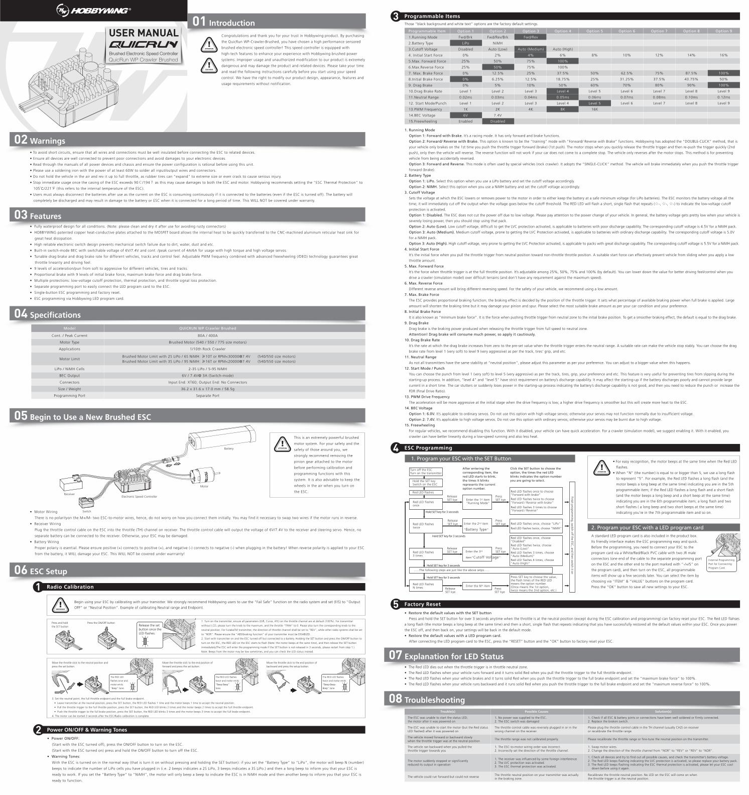
1.Running Mode
2.Battery Type
3.Cutoff Voltage
4. Initial Start Force
5.Max. Forward Force
6.Max.Reverse Force
7. Max. Brake Force
8.Initial Brake Force
9. Drag Brake
10.Drag Brake Rate
11.Neutral Range
12. Start Mode/Punch
13.PWM Frequency
14.BEC Voltage
15.Freewheeling
Option 1
Fwd/Brk
LiPo
Disabled
0%
25%
25%
0%
0%
0%
Level 1
0.02ms
Level 1
1K
6V
Enabled
Option 2
Fwd/Rev/Brk
NiMH
Auto (Low)
2%
50%
50%
12.5%
6.25%
5%
Level 2
0.03ms
Level 2
2K
7.4V
Disabled
Option 3
Fwd/Rev
Auto (Medium)
4%
75%
75%
25%
12.5%
10%
Level 3
0.04ms
Level 3
4K
Option 4
Auto (High)
6%
100%
100%
37.5%
18.75%
50%
Level 4
0.05ms
Level 4
8K
Option 5
8%
50%
25%
60%
Level 5
0.06ms
Level 5
16K
Option 6
10%
62.5%
31.25%
70%
Level 6
0.07ms
Level 6
Option 7
12%
75%
37.5%
80%
Level 7
0.08ms
Level 7
Option 8
14%
87.5%
43.75%
90%
Level 8
0.10ms
Level 8
Option 9
16%
100%
50%
100%
Level 9
0.12ms
Level 9
Programmable Item
07 Explanation for LED Status
08 Troubleshooting
03 Features
02 Warnings
04 Specifications
05 Begin to Use a New Brushed ESC
06 ESC Setup
Programmable Items3
ESC Programming4
Factory Reset5
CAUTIONS
ATTENTION
01 IntroductionUSER MANUAL
QuicRun WP Crawler BrushedBrushed Electronic Speed Controller
Those “black background and white text” options are the factory default settings.
1. Running Mode
Option 1: Forward with Brake. It’s a racing mode. It has only forward and brake functions.
Option 2: Forward/ Reverse with Brake. This option is known to be the “training” mode with “Forward/ Reverse with Brake” functions. Hobbywing has adopted the “DOUBLE-CLICK” method, that is
your vehicle only brakes on the 1st time you push the throttle trigger forward (brake) (1st push). The motor stops when you quickly release the throttle trigger and then re-push the trigger quickly (2nd
push), only then the vehicle will reverse. The reverse function will not work if your car does not come to a complete stop. The vehicle only reverses after the motor stops. This method is for preventing
vehicle from being accidentally reversed.
Option 3: Forward and Reverse. This mode is often used by special vehicles (rock crawler). It adopts the “SINGLE-CLICK” method. The vehicle will brake immediately when you push the throttle trigger
forward (brake).
2. Battery Type
Option 1: LiPo. Select this option when you use a LiPo battery and set the cutoff voltage accordingly.
Option 2: NiMH. Select this option when you use a NiMH battery and set the cutoff voltage accordingly.
3. Cutoff Voltage
Sets the voltage at which the ESC lowers or removes power to the motor in order to either keep the battery at a safe minimum voltage (for LiPo batteries). The ESC monitors the battery voltage all the
time; it will immediately cut off the output when the voltage goes below the cutoff threshold. The RED LED will flash a short, single flash that repeats (☆-, ☆-, ☆-) to indicate the low-voltage cutoff
protection is activated.
Option 1: Disabled. The ESC does not cut the power off due to low voltage. Please pay attention to the power change of your vehicle. In general, the battery voltage gets pretty low when your vehicle is
severely losing power, then you should stop using that pack.
Option 2: Auto (Low). Low cutoff voltage, difficult to get the LVC protection activated, is applicable to batteries with poor discharge capability. The corresponding cutoff voltage is 4.5V for a NiMH pack.
Option 3: Auto (Medium). Medium cutoff voltage, prone to getting the LVC Protection activated, is applicable to batteries with ordinary discharge capability. The corresponding cutoff voltage is 5.0V
for a NiMH pack.
Option 3: Auto (High). High cutoff voltage, very prone to getting the LVC Protection activated, is applicable to packs with great discharge capability. The corresponding cutoff voltage is 5.5V for a NiMH pack.
4. Initial Start Force
It’s the initial force when you pull the throttle trigger from neutral position toward non-throttle throttle position. A suitable start force can effectively prevent vehicle from sliding when you apply a low
throttle amount.
5. Max. Forward Force
It’s the force when throttle trigger is at the full throttle position. It’s adjustable among 25%, 50%, 75% and 100% (by default). You can lower down the value for better driving feel/control when you
drive a crawler (simulation model) over difficult terrains (and don’t have any requirement against the maximum speed).
6. Max. Reverse Force
Different reverse amount will bring different reversing speed. For the safety of your vehicle, we recommend using a low amount.
7. Max. Brake Force
The ESC provides proportional braking function; the braking effect is decided by the position of the throttle trigger. It sets what percentage of available braking power when full brake is applied. Large
amount will shorten the braking time but it may damage your pinion and spur. Please select the most suitable brake amount as per your car condition and your preference.
8. Initial Brake Force
It is also known as “minimum brake force”. It is the force when pushing throttle trigger from neutral zone to the initial brake position. To get a smoother braking effect, the default is equal to the drag brake.
9. Drag Brake
Drag brake is the braking power produced when releasing the throttle trigger from full speed to neutral zone.
Attention! Drag brake will consume much power, so apply it cautiously.
10. Drag Brake Rate
It’s the rate at which the drag brake increases from zero to the pre-set value when the throttle trigger enters the neutral range. A suitable rate can make the vehicle stop stably. You can choose the drag
brake rate from level 1 (very soft) to level 9 (very aggressive) as per the track, tires’ grip, and etc.
11. Neutral Range
As not all transmitters have the same stability at “neutral position”, please adjust this parameter as per your preference. You can adjust to a bigger value when this happens.
12. Start Mode / Punch
You can choose the punch from level 1 (very soft) to level 5 (very aggressive) as per the track, tires, grip, your preference and etc. This feature is very useful for preventing tires from slipping during the
starting-up process. In addition, “level 4” and “level 5” have strict requirement on battery’s discharge capability. It may affect the starting-up if the battery discharges poorly and cannot provide large
current in a short time. The car stutters or suddenly loses power in the starting-up process indicating the battery’s discharge capability is not good, and then you need to reduce the punch or increase the
FDR (Final Drive Ratio).
13. PWM Drive Frequency
The acceleration will be more aggressive at the initial stage when the drive frequency is low; a higher drive frequency is smoother but this will create more heat to the ESC.
14. BEC Voltage
Option 1: 6.0V. It’s applicable to ordinary servos. Do not use this option with high voltage servos; otherwise your servos may not function normally due to insufficient voltage.
Option 2: 7.4V. It’s applicable to high voltage servos. Do not use this option with ordinary servos; otherwise your servos may be burnt due to high voltage.
15. Freewheeling
For regular vehicles, we recommend disabling this function. With it disabled, your vehicle can have quick acceleration. For a crawler (simulation model), we suggest enabling it. With it enabled, you
crawler can have better linearity during a low-speed running and also less heat.
Trouble(s) Solution(s)Possible Causes
1. No power was supplied to the ESC. 2. The ESC switch was damaged
The throttle control cable was reversely plugged in or in thewrong channel on the receiver.
The throttle range was not calibrated properly.
1. The ESC-to-motor wiring order was incorrect.2. Incorrectly set the direction of the throttle channel.
1. The receiver was influenced by some foreign interference. 2. The LVC protection was activated. 3. The ESC thermal protection was activated.
The throttle neutral position on your transmitter was actuallyin the braking zone.
1. Check if all ESC & battery joints or connections have been well soldered or firmly connected.2. Replace the broken switch.
Please plug the throttle control cable in the TH channel (usually CH2) on receiveror recalibrate the throttle range.
Please recalibrate the throttle range or fine-tune the neutral position on the transmitter.
1. Swap motor wires.2. Change the direction of the throttle channel from “NOR” to “REV” or “REV” to “NOR”.
1. Check all devices and try to find out all possible causes, and check the transmitter’s battery voltage. 2. The Red LED keeps flashing indicating the LVC protection is activated, so please replace your battery pack. 3. The Red LED keeps flashing indicating the ESC thermal protection is activated, please let your ESC cool down before using it again.
Recalibrate the throttle neutral position. No LED on the ESC will come on whenthe throttle trigger is at the neutral position.
The ESC was unable to start the motor (but the Red statusLED flashed) after it was powered on
The vehicle moved forward or backward slowlywhen the throttle trigger was at the neutral position
The ESC was unable to start the status LED; the motor after it was powered on
The vehicle ran backward when you pulled thethrottle trigger towards you
The vehicle could run forward but could not reverse
The motor suddenly stopped or significantlyreduced its output in operation
• To avoid short circuits, ensure that all wires and connections must be well insulated before connecting the ESC to related devices.
• Ensure all devices are well connected to prevent poor connections and avoid damages to your electronic devices.
• Read through the manuals of all power devices and chassis and ensure the power configuration is rational before using this unit.
• Please use a soldering iron with the power of at least 60W to solder all input/output wires and connectors.
• Do not hold the vehicle in the air and rev it up to full throttle, as rubber tires can “expand” to extreme size or even crack to cause serious injury.
• Stop immediate usage once the casing of the ESC exceeds 90℃/194℉ as this may cause damages to both the ESC and motor. Hobbywing recommends setting the “ESC Thermal Protection” to
105℃/221℉ (this refers to the internal temperature of the ESC).
• Users must always disconnect the batteries after use as the current on the ESC is consuming continuously if it is connected to the batteries (even if the ESC is turned off). The battery will
completely be discharged and may result in damage to the battery or ESC when it is connected for a long period of time. This WILL NOT be covered under warranty.
Battery
Motor
Receiver
Switch
Electronic Speed Controller
Press and hold the SET button
Press the ON/OFF button