Embed Size (px)
Citation preview

AFML-TR-76-173I
00pA
* EXPLORATORY DEVELOPMENT ON DURABILITY OFADHESIVE BONDED JOINTS
BOEING COMMERCIAL AIRPLANE COMPANYP.O. BOX 3707SE~ATTLE, WASHINGTON 98124
OCTOBE~R 1976
TECHNICAL REPIOJT AF~ML-TH-76173FINAL REP1OUT FO1R PELUOD FEBRUARY 1974 -OCTOB3ER 1970
LApproved for public relase distribution unlimnited
____ 13repared forcm LL- AIR FORCE MATLERIALS LABIORATORY
AIR FORCE SYSTEMS COMMANDSWRIGHT-PATTERSON AIR FORCE BASE, OHIO 45433

NOTICE
When Government drawings, specifications, or otherdata are used for any purpose other than in connectionwith a definitely related Government procurement operation,
V the United States Government thereby incurs no responsibilitynor any obligation whatsoever; and the fact that the governmentmay have formulated, furnished, or in any way supplied thesaid drawings, specifications, or other data, is not to beregarded by implication or otherwise as in any manner licensingthe holder or any other person or corporation, or conveyingany rights or permission to manufacture, use, or sell anypatented invention that may in any way be related thereto.
The data in this report is merely a factual presentationof the results of the particular tests performed and is not to
Sbe used, copied, or referenced for advertisement purposes.
This report has been reviewed by the Information Office(10) and is releasable to the National Technical InformationService (NTIS). At NTIS, it will be available to the generalpublic, including foreign nations.
This technical report has been reviewed and is approvedfor publication.
W. M. ScaRd~ino (AZ1'M/4XZ)' rMEProject Engineer
I FOR THE COMMANDER
ALBERT OLEVITCH, ChiefI) Materials Engineering Branch
Systems Support Division
I'/
Copies of this report should not be retu d unlessreturn is required by security considerations, contractualobligations, or notice on aspecific document.
I - ~l ~t'

UNCLASSIFIEDSECURITY CLASSIFICATION OF THIS PAGE (Mlien Data Entered)
DOCUENTAION AGEREAD INSTRUCTIONS/ ORT DOUETTO AEBEFORE COMPLETING FORM
OATHRY 2. GOVT ACCESSION No. 3. RECIPIENT'$ CATALOG NUMBER
"AFM R-76-173... TY- ""DR COVERED
W Exploratory Development on~ DrbltofIy FirnaAdhesive Bonded Joints~ e 4O 6
Fl PORT NUMBER
crc au4W J. C/IMillan IA
91. PERFORMING ORGFICE IO NAME AND AD DRESS PO EET RJCAoirg Foremamercials Laorpatuoryan
WSeh-attlerWshigon 98124 hioN 4543368
It.~~~~~SC~IL NA~OLN OFC AE N DRS
T,, *UP*EMNTI7NO
Air st c Systemt s Comman aheemd )3.~t NUMBER~e OFa
omethos tUVON STTE MEN (dativ litomt R maeprt) sai rcseadt evlpacreaim ewettApprovdtoryts pubmic~ oeandiserv; distribtonlim ited.
ThJAtmtto vlainwstomrttderyi h '~~dm adrslswr Itls~ na
17-elu technicaIO rellori.N (tM41 he& 75.3.OROW1 DUrlil20,ly o~ft~ Adehe Ummi Jont. Perury19
ii ~ ~ ~ ~ ~ s DD L&' 1A413 N'o'~is 'o g uo

51? P. WIP rC 71 ý;-
UNCLASSIFIEDSECURITY CLASSIFICATION OF THIS PAGE(When Data Entered)
20. ABSTRACT (Continued)
Four stressed durability test methods were selected for the test program: -
[5A thick-adhecrend lap-shear specimen (Mode I and Mode 11 load ing),*3Q A thick-adherend double cantilever beam (DCB) specimen (Mode I lgpding)
(1A thin adhierend DCB specimen (wedge test, Mode I loading) 'a'd.,lA thick adhierend single- cantilever beam (SCB) specimen forlioncycoxnb sandwichevaluation (Mode I and Mode 11 loading).
Alloy, adherend surface treatment, adhesive primer, and adhesive interactions were evaluated.The materials and processes used were:
~ ~iI~:2024--T3, 2024-T3 clad (1230 alloy), 7075-T6, and 7075-T6 clad (7072 alloy)C2 Adljeshi',.s: FM 123-2 and EA 9628 250'F curing adhesives, and AF 143 and PL 729_i
3500 F curing adhesives;r tijmerý BR 123 non-corrosion-inhibiting primier, BR 12'7 corrosion-inhibiting primer, andEC 391.7 and PL 728 corrosion-inhibiting primers for use with the two 35OfF curingadhesives~
C4 k 4soe 1c ratetpigess Optimized -PL etch, chromic acid anodize. andphosp-fi5-ic 'acid anlodizec./
A~wnnum~emc~ombcore: Standard core, Dura-Core and CR Ill corrosion-resistant cores,and phosphoric acid anodized core.
Results of this investigation have shown that:I.Two basically different test specimnii configurations tire required to assess adhesive bonded
joint durability performance. one that emphasizes combined Mode I and 11 loading and onethat evaluated Mode I loading o'nlv,
2.Cyclic loading otf bonded joints is more damlaging to the bondlines than steady-state loading.,3.Phosphoric acid anodiz~ed adheurend surfaces showed the best over-all durability jerformaac,ý
in both nIetal-to-nietal bonds and honleycomb Core bonds.4. The presence of cad in the bonldhine inceiases the teiideiwy for crevice corrosion.5. Corrosion-inhibithig primers (ChAP) improved thle stressed durabfily performniice ot boiildd
specimenvis over that of the nioii-co(rrosloni-iniibiLitinig primer. ClAP did not prevent crevicecorrosion.
* 16. A laboratory tcst/in-survive perforilance correlation hias beenl demioinstrated under Modk: Iloadfingp conditions.
Jo.io~hsuyo 'SCrOsi durability has beeni recommendled to better understand how 1116.
-. . lulorliiatioii canl be applied to design of critical luad-earryitig aircraft Structure.*Modh: I: 011ening mlodle tcleamage)
* Mode fl: Forward Shear (edge Sliding)

* FOREWORD
*This technical report was prepared by the Hoeing Materials Technology Unit, Boeing Com-miercial Airplane Company, Renton, Washington, under USAF Contract F3361 5-74-C-5065,Project FY-1 457-00616/7381. The program was administered by the Systems SupportDivision of the Air Force Materials Laboratory, with Mr. W. M. Scardino (AFML/MXEi asI ~project engineer. An interim technical report under the same contract covering the periodI February 1974 to I July 1974 was published in February 1975 as AFML-TRq75-3"4Durability of Adhesive Bonded Joints."
Mr. J. A. Marceau is the principal investigator and Mr. J. C. McMillan is the programn manager.T'he authors wish to acknowledge the efforts of F, E. Coverson and T. Gaines of BoeingMaterials, Technology and T. Kane of Boeing Structural Testing laiboratory.
IJ

TABLE OF CONTENTS
Page
1.0 INTRODUCTION. .. .......... ............ .................
2.0 SYNOPSIS OF PHASE I AND PHASE 11 RESULTS .. ... . .......... 62.1 Stressed Durability Test Methods .. .. .............. ........ 6212 Adherend Surface Preparation. .. ............ .............. 7
3.0 PHASE III RESULTS .. .. .. ....... . ........ .. ...... .... 93.1 Nondestructive Inspection (NDI) of Bonded Assemblies. .. ......... 1112 Verification of Test Methods (Ts )............1
3..1 Sutane-Stress Thc-Adherend Lap-Shear Tests. .. ......... 13.2.2 Sustained-Stress Thick-Adherend DCH Tests . . .... , 1 63.2.3 Final Justification of Test Methods. .. .......... ...... 18
3.3 Influence of' Test Temperature (Task 6). .. ............ ...... 1 93.4 Effect of Test Dur~ation on Sustained-Stiess Tests (Tusks 2, 3, 5, and 10) 20
3.4.1 Thick-Adherend Lap-Shear Tests (Task 2). .. .. .......... 203.4.2 Thick-Adherend DCII Tests..............23.4.3 Honeycomb SCII Tests (T~asks 5 and 10) .. .. .......... ...2
3.5 Cyclic Stress Tests (Tusks 4 and 8) .. ...... ............ .... 203.5.1 Thick-Adhevrend Lap-Sheuar C'yclic Load Tests .. .... ....... 63.5.2 Thiek-Adherend DCII Cyclic Load Tests (Task 8). .. .. .... 30
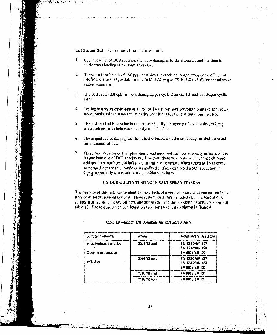
3.0 Durability Testing in Salt Spray (Task 9). .. ...... .............3.7 L~ab Test/In-Service Correlation (Task 7). .. .......... ........ 38
3,731 Durability Testing of Commercial Aircraft .. .. ... . ...... 383.72 Durability Testing of Air Force Aircraft .. ........ ...... 41
4.0 PHASE IV, SPECIMENS FOR OUTDOOR EXPOSURE .. .. .. ....... 47
5.0 DISCUSSION. .. .. ....... . .. ...... .. ...... ..... . .... 485.1 Stressed D~urability Test Methods. .. ... . .. ...... .. .........5.2 Long-Term Einvironmnental Et1fecig. .. .. ..... . ............ 485.3 Stressed Durability of Clad and Bare Alloys......... .. I .. 35.4 luservice Behavior and Streswed D~urability Test ( .rrations....5.5.3 Optimum Temperatuire for Stressd D~urability Tests....... . .. . . 3
5. Dcumenting Test Nlethotis ................. 545.7 General Dilscussion .. .. .............. ........ .......
5.7.1 D~urablilty of~ Honeycomb Satidwivit (onstnictioit . . . . . . 555.7.2 Corroiloti-Inluibiting Adhesive P~rimes 3,,,... 55.7.3 Adliertud Surfaces.. .. ... . ........ .. ...... .... 56
..4 Adhesives . . . . . . . . . . . . . . . . . . . . . 5
6.0 M'NCLUSI()NS..........................56. 1 Stressed lDumbl'ilty Test Methods... .. .. .. . . . .. ...
u6.2 Long-Tern EmtironmentuI litfecs *.. . ... .. ........ 57
PR~lix-43.t PAM
v

1'K 7 TABLE OF' CONTENTS (Continued)
Page
6.3 Stressed Durability of Clad and Bare Alloys...........586.4 Inservice Behavior and Stressed Durability Test Correlations . . .. 586.5 Optimum Temperature for Stressed Durability Tests. .. ........ .. 581~6.6 Documenting Test Methiods .. ...... .............. ........ 586.7 General Conclusions. .. .......... .............. ........ 59
7.0 RECOMMENDATIONS .. .................... 607.1 Stressed Durability Test Methods .. .... ............ ........ 607.2 Stressed Durability of Clad and Bare Alloys .. .. .......... .... 60
8.0 REFERENCES .. .... .............. ............ .......... 61
GLOSSARY. .. ............ .............. ............ ...... 63
APPENDIX A NONDESTRUCTIVE INSPECTION (NDI) OF BONDEDTEST ASSEMBLIES. .. ........ .............. ............ .... 139
APPENDIX B LOADING VALIDITY OF MODIFIED STRESS CORROSION JIG 144
APPENDIX C WVEDGE TEST FOR ADHESIVE BONDED SURFACEDURABILITY OF ALUMINUM . ,.. .. .. .. .. .. .. .. ... 151
1 V1

LIST OF ILLUSTRATIONS
No. Page
I Loading Modes Possible in Bonded Materials ............. 652 Thick-Ad herend Machined La p-Shecar Specimen ............ 653 Thick-Adherend DCB Specimens ................. 664 Thin-Adherend LD(B Specimen (Wedge. Test) ............. 685 Thick-Adherend SCB Specimen .................. 696 Thick-Adherend Lap-Shear Modified Loading Fixture 707 Fnvironmiental lIxposure Chamber for 14''Cnesn Humidity, Showing
Arrangement or' ICB and Stressed Lap-Shear Specimens .. ..... . ...... 708 Typical Thick-Adherend 1,ap-Shecar Specimenl Failures for Sustained-Stress
Tests F\-posed to I 401 jtondenising H-Iumidity. .. .. .... ... . ........ 719 l)CB Specimen Exposure Results .. .. ..... . ...... ....... . ...... 72
10 Opened D('B Specimen-, Bonded with 111 724-3/111 728. .. .. .. ....... 78ii Opened lXii1 Specimens Bonded Willh At,43E 3917 Sse. .... 80
12 Opened IX11 Specimens Bondled Willh FM 1 23-2/111 127 System......821 3 Opened l)(.B Specimens Bonded With IA Q628/BR 127 System. .. ....... 414 Influence of Test Tem peratutre on MBi Specimen. .. ... . .... ...... 6Is Influence of' Long-rn Exoure Onl IX'l Specimlenl. .. .. .... ....... 881o Influence of Adhlesive Primers onl ICB Specimen .. ... . .. ..... . .... 9117 Typical F~ai lure Modes and Filiform Corrosion inl Bodlineltis ofc l)CB
Speimeniis (omparinig ClAP and non-CIlAP Primer After 82 WeeksFxpoirte ito 40' P/(otdensing litiwidlity .. ..... . .. ............ 3
IS Influence of Ilolweyconill Core anld Face sheet Surfice Treatmenvits OnlFriwironmilentitl D~urab'ility .9 ........ 44
IQ) Failuire Ntodes In tilhe Pretet.est.sT.i and Postlest Areas of SCII SpectimensBiondled with 1.A 4h28 and Exposed ito I 40F/Conidensing Hlumidity . . . . 7
20 Load Profiles for Slow Cycliv Loading of La~p-shear Specimens. .. ........ 421 Cyclic Load Mahleline for lap11-shear D~urab'ility 'Ueilsti .. . .l.. .. )22 Tlypical Fminiples of' Failure, Modes for Slow Cycle Fatigue tO,$ and I() Cph) l 10023, ('onip~a'isot of Slow C~yclic FatIigue for 0.8 Cp1u (B10l) aittl 10 C)l cp. .. ...... 024 . aiu IetArrangemetit Ior Thick-Ad~ltetend Lull-Shevar Speimensir
(Envronient11Cambr Surroundsh lthe speimenllv.).... .. .. .. . ....15 Fast CYCle Stress Resulls ..... .. .. .. ......... . . 1032(s Falilure Nimde Cliracteristio kol' hivk Adlieretid Lip Shear Specimens
TeSted ait 18001 cpml. It : 0.06Ci.. .. ... . .. ............. 0827 'iyplcal hip-Shevar Failurosat I SMt vp. 10.14-T3 Mire Bonded Withi
2 1opope'aphlical Features Which Appear Tki le Fatigue Strialiotis atAdliesiv c-Prtimer lilerlftce Zonle . .,,. .. .. .. . .. .. . .11
t)Fast Cyclicý Load hiachinev for lD'B SIveitivons... .. .... .. ..... l.4) Slow (Cwhc Load Machtine for IXiI SpdIX-1v ls . . . .. .. .. . .. 112
31Cyclic ('tack L.;towtil lt-ale Data , . , . , , . I132 Fracture Appeawtnceý From Cyclic Loading (if lK'Ii Spk eciesE )i
17 l~ Adltesv.-riw ther Systent. .. .. .. ... . .... ... . .... ..... It's
vii

"MR, ý7L 7,
LITOF ILLUSTRATIONS (Continued)
No. Page
33 W~~edge lest specimens Exposed to 57( Salt Spray. .. .. ....... . ...... 11934 Specimen Configuration for Commercial Aircraft A. .. ... . .. ....... 12435 Specimini Configuration for Commercial Aircraft 1B. .. .... ........... 12530 SpeCillil~u C'onfiguration for Comnmercial Aircraft C.. .... . .......... 12o37 Specimen C'onfiguration for Commercial Aircraft 1) .. ... . ...... . .... 127
38 Ssained-Srs La-har Results of Specimewis Machined From Aircraft Aand B3 Comnponents................... .. ..... . . ..... .. .. .I 28
39) Wedge Test Results of Specimens Machined From Aircraft' A and 1BComl)ponienlts . . . . . . . . . . . . . . . . . . . . . . . . . 1
40 Section of Aircraft C (omponent Showing, Areas Where Test Spechimens WereTakeil.............................. .... ... I 130
41 WVedgei'Yost Results ot Specimens Mlachined From Aircraf~t C and 1)Components. .. .... ....... . .... ....... . ...... ........... 1 31
42 Tlypical Wedlge Test and Peel T'est Specimens From Aircraft (............3
43 Tlypical Blonded Hloneycomb Paniel Willh Cioseouts From Air F'orce Aircraft 131244 Typical (Cross Section of I loneycomlil Strucoture With Tapered Closeout . 13241 Conll'iguii j ajtins oft Specimitens Fabricated From Air Force Airvralt IDeaihi 1I 334 Wedge' 1'est Resuilts of Spevncimes Machinied From Air F'orce Aircraft .... 13447 Susta i tiedk-Stress Thi ck-Adhberend LpSerlm-tkulreResu Its .... 1 34)
* 48 ~~Comlpa.risonl of' Bonded Alumoin nu F~at igue (Crack Griowth ItIat Willit PublishedD~ata for kit igue Crack GrowthI in Aluminum Alloys . . .... .. .137
A-1 Neutiron Rkadiograph of kainihatedl 2024-T.' ('lad Paneol Section f'or* ThitA-Adhereidu D)(II Specitneuuis Showing Voids in One or Miore Houdlihic I 140
It- I I ap-Shecar t oakditig Fimure f'or Suistainctd Stress ltirahility'lTesting . . . . 144It- Sirauin Cauge ILoc, no on iluick-Adhorenil hipl-Shuu Specimen . I 145
*11-3 TIhick-Adlivrond I ap-Shear Modified Loading I, Ii tireý ,.. ... , 147C- I (ravk I~.memmnsivi.Secilken ('okifiguritjoll...... . 153

LIST OF TABLES
No. Page
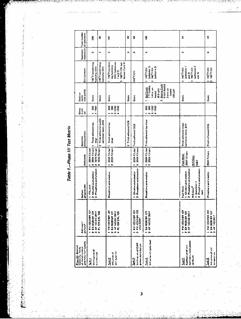
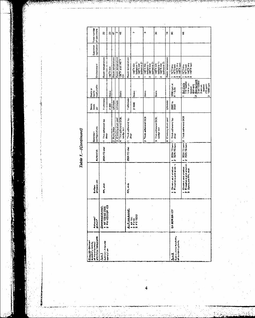
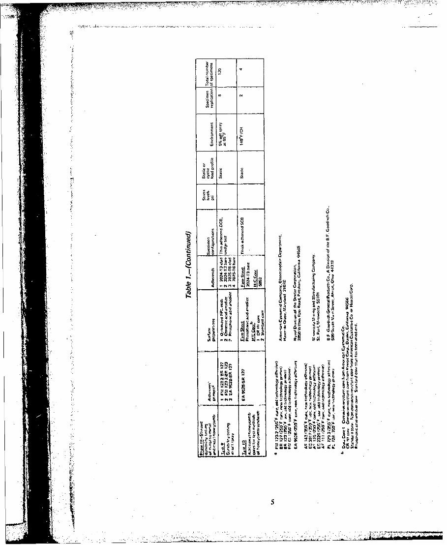
I Phase ilI 1'st matrix . . . . . . . . . . . . . . . . . . . . . . 3I. 2 Rationale for Selection of Materials. Processes, and 1est Environments.
3 Detailed Processing D~escription . . . . . . . . . . . . . . . . . . 104 B~aseline Shear Strengthls - Room Tempert, .i ....... ............... 12
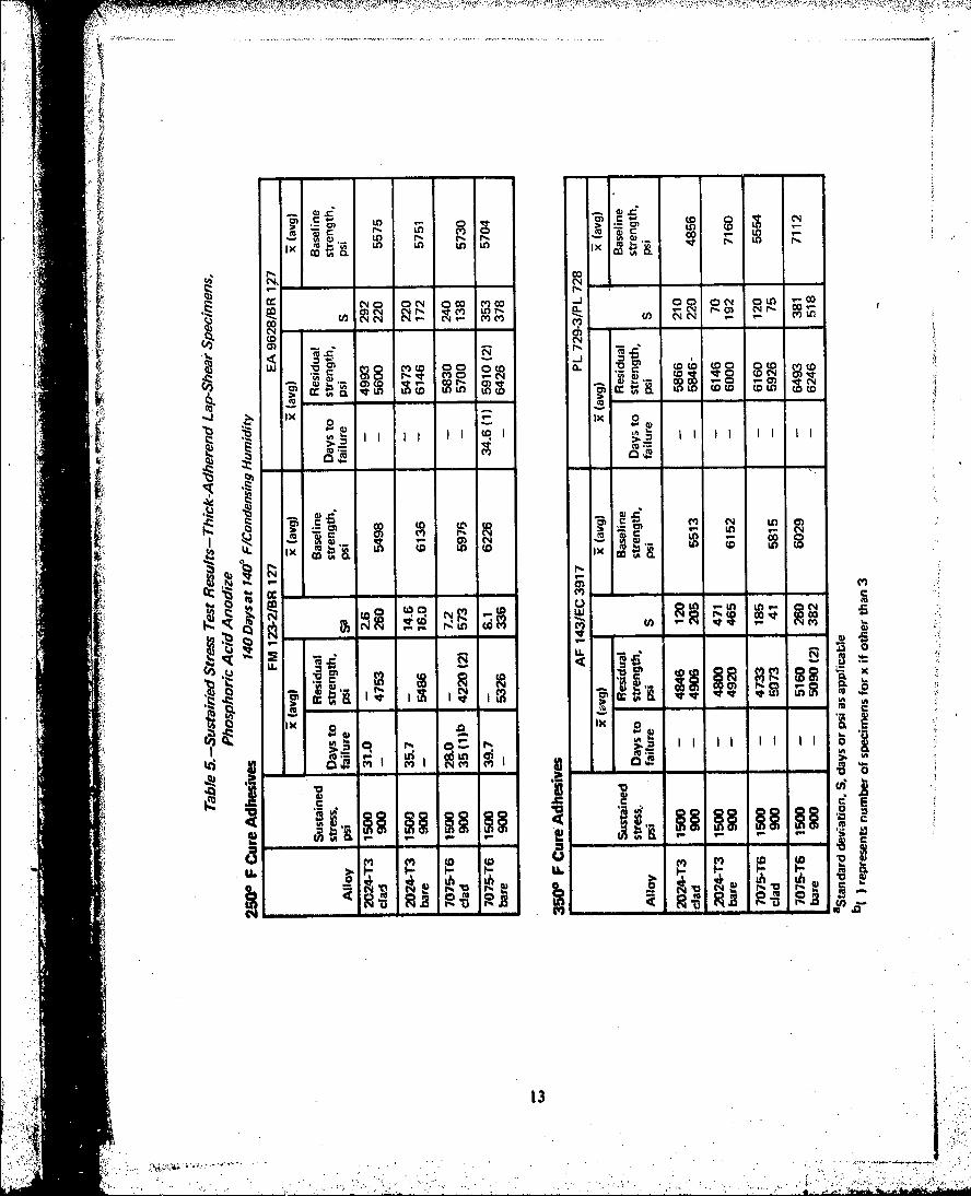
5Sustainied Stress Test Results- Thick-Adh. 4 ,id Up-Shecar Specimens,Phosphoric Acid Anodlize .. ........ ............ ............. 13
SSustained Stress Test Results Tlmick-Adhlerermd Lap-Shear Specimens,C'hromiic Acid Anodlize .. ........ .............. ........ 14
7 Sustained Stress Test Resutlts Thick-Adherend LUp Shear Specimens.FIT~ EtAch ........................................ ............... 15
8 Long-'lerni Suistained Stress 'lest Results ((9 Months)- Thick-AdherendLap-She~ar Specimens, Phosphoric Acid Anodiz.e. .. ................. 21
9) Materials and Proces'ses Used I'or Single C'antilever lcani (S('lI Specimens 2410 Slow Cyclic Stress Test Results - hick-Adherend lap-Shear Stweiniens,
Phosphoric Acid Anotlin .. .. ...... .............. ........... 27I I Slow Cyclic Stress Test Results Tlhick-Aillwreimd Lap-Sheam' Spe~lcimen..
Phosphoric Acid Anotdite .. ...... .. ... ..28..
191~e for (Nil Spray Tests ..
ProcessesI'ili ill Salt u Sla~ iVc Prparatwion...................4
AI ( Co m r i nsAi cra t Iotu 1)1 o De t oails N . . . . . . ta. . . . . .l.e. . 48
IS ArF ircraf tiBonded Details .I.o.d.d. . .co. . . . . . . 43It Rsiua Roo Nksuenlimaent Iof Iikalmnd apShear S prnt ArFreAircras
11-2 mem .euei e~ .l .a~ het i. .tdle . . . . . . . . . . . . . .20Tiv-iIirn I tIV-I'vt esItilsArFeArrf 11muokiM ll .. 4
It M trasai rcse o 'iwIV3oii i .. 4
1.0 INTRODUCTION
The performiance of bonded joints in aircraft strulcture has varied in both military and comn-mercial applications. For the most part, bonded structure has provided excellent servicepertformance over mtany years; however, some bonded parts have experienced (lisbond withvarying degrees of subsequent bondline corrosion after relatively short service exposure.
Traditional test and performance evaluation methods have not been capable of precludingdisbonding and corrosion in service, and as a result serious qluestions concerning the relia-bility of bonding have been raised. The traditional test methods generally encompass threeareas: (I ) tap-shear testing as a function of temiperatutre. (2) peel testing as a function oftemperature, and '3) exposure of unstressed lap-shear specimens to various environments forrelatively short periods of time tcg,30 days) before testing. Ani examination of the fracturedtraditional test specimrens showvs that these tests do not duplicate the features characteristicof service disbonds.
lin recent years, it has been found that testing bonlded joints under a sustained stress whilesimu tltaneously exposing thet Specimens to warmn/wet environmients resuilts in failures offthebond at stresses far below the ultimate stress mevasurctd at the exposuire temnperatutre. Thistype of stressed durability test is capable of showing differences lin perforturnce betweenadhesive s-ystemis and various process parame~ters. lin addition. thle faire: modes of improperlyprocessed bondments teqtedl it) this manner have anl appearance characteristic of service
disbonds:ie.intorfacial failures.
Thu objectives of this contract were to.,
I. eterminite a sound mnethod of evaluating stressed durability of adhesively bondedstructural altimninnuivatrials. including an assessment of the inerits of cyclic versusi
tedy-stare Siste' testing and of thke. effect load proflte IWS Onl stressed durability testing.
* . ~~2. E~valuate thev lon-torni effects of eonvironenivt ol stressed adhesive bldsint nta~Metal (kuilwninumn-to-ah'intluml) and alumlinum honley0comb1 sandwich constructilolls.
K. Werterne thet differente lit stre ed envirounmental durability be-tween ca tid ba realuntinurn1 alloys.
4. Asses. lthe correlatioti bet wen hinsmrvi Whalwvor. ot adhesivoly bondetaireral't aswill-Mlies and stressedj durability tests.
S. Iletei itine1 th1V opitinniiitloltemerature luir ~wirnn tesddurability tebts of structuriloerosimce UdlLI0',4-s
~. lkwilop or lierfeet streoseWl thirihi'ity tests for inet, lto-utitelafand tndic lwiand tdocuuest those in ASTAI ICAt ilefiltdl Wrina.

The program was conducted in four phases:
0 Phase I Literature survey
0 Phase 11 Selection of durabihity test methods
* Phase 11I Stressed durability testing of metal-to-metal bonds and metal hioneycomb
0 Phase IV Specimens for outdoor exposure
Phases I and 11 were completed early in thle program, and these results have been publishedin Air Force Technical Report AFML-TR-75-3 (ref I)
Phas IItos~dof 0tss wihwr main effort of the program and were designed
0 Task 3 Verification of corrosion-nhibithingprimer (CIAP) contribution
I.Task 4, Influence of cylclodn
0 Task S Application of test methodi to hioneycomb sandwich
0 Tus~k 6 Influence of test wanporaltur
* 'rusk 7 Lab testjlinwrvlce correlution
0 Task 8~ Cyclic slrem durability of bonded systems
*o TAk9 Durability testing~ inl &ilt spray
a Task 1) Additional honeycombi cores for honey'combl sanldwich tosis
Tied mtoi 34 for vach of these tasks. hncluding tile total aullwr of specimenls toited, 6s
lllwse IV consistd of providing tile Air Foree with test stchlnons.
*Tile rollowhiig ecin present o brýei summiary of tile Plum-~ I andk Illhase It reo.uhs (reportedIll ter. 1), and dotailed results of Phae lIll, With a dlseuwsoa of' Ilows roiults
- --- _ __ __ _ __ _ ___'_
a, YN
_-0 ___' _ __
O C C .0... .
')i" . .,,---
b•• " '' '" " "" " ... . " . ' ' i, " , " " : .:: • -.: '. .'t ;" • . '"" " -; " ".S" - .• " ) ' " - "' t' " " .' ."- j j : . ., . . " ."N. z z . '? '." " .c , : .'• ,, ;- • °
0. 00 0
00.x
j-0S
u00
03~I fn30,0
0, 000 0 0
0, ~ ~ ~ ~ ~ m 0,0CDI I I IO~~~U~~~ mU J0~2~
2~c co~2UUUU0
C L - , 0 Oco - 3J00, LU
E 2 ~ S E ~ S C,
2~ ~ ~ ~ ~ ~ ~ ~ ~~~~l 0Mo 3~0--.-.---.~0r.--N3
c 10 O I
0 ~ - ON . (N ( cc
it 6L E
0, 0, U~! ~CV5
0 E~n 0 o.~ ~o41
.. !ý 7 7 7l7 *.7 7 5 7 7 1 . . . ' z T ,* * r ~ * t
-77
Cc
t0 N
CL
II
0 sat
4,SL4
oh 0
ti 1,
c4''v0
-ftt - -M

F,~~~M~ KA1qPO .7
2.0 SYNOPSIS OF PHASE I AND PHASE II RESULTS1
The purpose of Phase I was to review the literature and to survey adhesive manufacturers,prime aerospace contractors, and any other pertinent sources to determine currently usedmethods of stressed exposure durability testing and practices relative to the types ofaluminum adherends presently being used or contemplated for use in adhesively bondedaerospace structure. The purpose of Phase II was to assess the various durability test methodsand select the methods for use in Phase III of this program. In addition, surface preparationprocesses were to be assessed and three selected for use in Phase III.
More than 700 references (articles and abstracts) were reviewed. These references includedsuch categories as test methods, specimen stress analyses, faihi'e mechanisms, adherendsurface preparation, environmental effects on bonds and adhesives, corrosion, and service
failure analyses.
2.1 STRESSED DURABILITY TEST METHODS
Assessment of the reported test results revealed that a sustained stress applied to the bondlinewhen the specimen is simultaneotisly exposed to an aqueous environment causes some degreeof damage to occur. The degree of damage within the bond is a function of the stress level,
availability of water, temperature, and adhesive system.
Assessment of the test methods described in the literature revealed that all the specimenconfigurations, when stressed, have a load component normal to tile bond plane Present atthe load transfer edge of the joint. This loading mode is known as Mode I (opening mode).(See ,fig. 1.) Most specimen Configurations that are cantilevered. peeied, or utnder flatwisetension are exiosed primarily to Mode 1. Most other configurations have shear as the primaryloading mode and Mode I as the secondary mode. This type of shear is known as Mode 11(forward shear), (See fig. 1.) A third loading mode known as Mode Ill (sadewisv shear, fig. I)is not present in any of the test configurations reviewed,
Selection of te-st methods and specimen configurallons for Phase Ill was based oi the:following criteria:
I. The test spelmens must relate to real structure loading modes.
2. Mode I loading muIst te controllable.
3. Mode II loading must IV Controllable,
4. The test niethod must yield qtuatiative resilts and not he subjective. A secondarygoal was to provide a SjVCl1110e1 that Inight lie used In tihe future to relate a fi'ieelemeill stresA alalysis of tll te• t specimenw configuration to a similar analysis of real
SRelsoried hin AFMIL-TiR.75-3 (tef I)
', ' , . " , ' , ., • . ' , '.' ' ,,,• . .' • • 6'• i
:',• ., ., , . ., -. . , . . _ • , .. , : ...

5. Fabrication of specimens must be reasonable, i.e., specimens must be relatively simple,must not require unusually close dimensional tolerances, and fabrication costs mnust below for programs involving large numbers of test specimens.
Based on these criteria, the four following specimens were selected as the most suitable formeeting the objectives otf the program. These conlfig urat ions relate best to thle two loadingmodes present in most test specimen configurations and in real structure.
0 Thick-adhierend machined lap-shear specimen.-These specimens are machined from twobonded I /4-in.-thick aluminum plates. Thle specimens are I in. wide and 7 inl. long,with a 1 /2'-in, overlap machined in the middle. (See fig. 2.)
* Thick-adherend double cantilever beam (DCB) specimen.--These specimens are machinedfrom two bonded I1/2-in.-thick aluminum plates (or four bonded 1/4-in, plates for clad3alloys, which are commonly available only up to 1/4-in, thick). Thle specinenls are I byI by approximately 14 in. (See rig. 3.)
0 Thiin-adberend l)CI specimen ("wedge test"). IThese specimens are cut from 6- by6-by 1/8-in. panels bonded together. Thle specimenis are I by 6 by 1/4 in. (See fig. 4.)
0 Tlhick-adherend single cantilever beam (SCI3) specimen.- These specimnils are cut frombonded sandwich assemnblies. Thle specimens are 3 in. wide and approximately 14 inl.long with a l/2-1In.-thick. test face shevet. (See fig. 5.)
WVith the exce-ption of thle thick-adlierend lap-shear specimen. the precedinig specimeons. dot" not require fixtures or exernil loading to maintain the sustained stress. ix.e, thevy arc svlf-
contained. To apply thle desired sustained stress to the lap-sltear specimen. a poirtableloading fixture was used. (See fig. 6.)
2.2 ADIIERUNI SURFACE PREPARATION
Tile criteria uised inl assossill; and seClecing tile surface preparation Processe's for u~se ill thisprograml wevre:
I. Processe which1 have gained acceptancex throughout the inidustry alter mlanly yuars ofsric histoy
2. roeseswhich represent new techntology as- related ito vivironmliental durabilitypevr1frnuIltce ol' bonded systemls.
W ased oil these criteria. tits. fl~lowinig three suiriktee treatmentsll Were W-seletd f'or tile Prop.raill:
I Il oeing IIII. etch ptrocesi, BAC 53 14, rev~sion V
Tilte tiadre wedge test qipeimenvi was nuot aceepied during 11ha11W 111111t was skils'e-tite-itly added to Itet progainii bvvitiske of 1tvliv ned for a very Inevxptensive. tiualitutive test
spIAen

WTT7 r .
2. Bell Helicopter chromic acid anodize process, BPS FW 4352, revision G
3. Boeing-developed phosphoric acid anodize process, BAC 5555
The FPL etch and the chromic acid anodize processes have gained wide acceptance through-out the industry and have many years of service history. It should be noted, however, thatthe FPL etch specified in the BAC 5514, revision F process includes process controls andtest requirements that are in excess of those normally applied in the industry. This processis sometimes called "optimized" FPL etch. The parameters for the "optimized" FPL etchhave been submitted to ASTM for membership approval to update ASTM standard D2651-67.(1973), "Standard Recommended Practice for Preparation of Metal Surfaces for AdhesiveBonding." The phosphoric acid anodize process is an example of new technology surfacepreparation.
1A
t
.1.I
*1'Ii-
II

3.0 PHASE III RESULTS
Specimen conlfigura tionis, with the exception of the thinl-adh~rend wedge specimlenl, andprebond surface preparations to be used in Phase Ill were selected in Phases I and 11. Atthle onset of Phase Ill, alloys, adhiesives, and test environments were selected. These arelisted in table 2 along with the criteria for their selection. Details of processes used in curingadhesives and primers and applying surface preparations are described in table 3.
Table 2.-Rationale for Selection of Materials, Processes, and Test Environmients
Subject Criteria Selection
MaterialsAluminum alloys Representative of alloys commonly used in 2024-T3 clad (1230 cladding alloy)
aerospace bonding 2024-T3 bare7075-T6 clad (7072 cladding alloy)707546G bare
Adhesivts 2504F cure current technology FM 123.2 (10 mil film thickness)250 F cure new technology with improved EA 9628 010 mil f ilm thickness)stressed durability
350 F cure now technology of current AF 143 (15 mil film thickness)________________interest to the Air Forc PL 729-3 (15 mil film thickniess)
Primers 25(fF use nonwCIAP primer, old technology BR 123 for use with FM 123.2250"F cure cotrrosionn Inhibit !nt adheusive BR 127 for use with FMprinter (ClAP), neow technology 123-2 and EA 9628360OF cure CIAP new tachnoluoy EC 3917 for use with A F 143
PL 728 for use with PL 729.3
Metal prebond Processes that have llained acceptance FPL etch, Boeing, BAG 5514,surfacit treatments throulllhoot the Industry with years of Rev. F
service htistoryChromle acid anodize, Ball
Lelicopiter, BPS FW 43-62,Rev. G. Method IA
Procesues thait represent neaw tlechioolouy Phosphoric acidl anudilae.rillauted to durahlility Owerlorwnco of Buoioin BAC 5655
Warl, Wett Its Rp n titi' of1mod4r0t to Severe 1 20'Flcotidonsloq humidityexposure eonditions~ codtOul th odist to aircrfilt ellvirol* 1WFcodnkg u.dt
4110t%. olg., levt! tempeitratute and I61O'icondallwou humlidityhiglh humioidity
Corrosivfe Ckloriewtv envitollillo 5% %alt spray at 9V~F
4.. .jOl

Table 3.-Detailed Processing Description
Material/process Processing details
AhsvsTemperature rise; 5.60 F/minCure: 225'-250'F for 90min
FM 123-2 Pressure: Metal1toinetal, 50 and 100 psiaEA 9628 .Honeycomb, 35 psi
AF 143 Temperature rise: 5.6"F/minPL 729-3 Cure: 3400 to 360'F for 60 min
Pressure: Metal-to-metal, 50 and 100 psia
Honeycomb, 35 psi
.2romet Application: SprayCure: (Noncurirtg) air dry a minimum of 1 hr
BR 123 at room temperatureThickness: Less than 0.0002 in. but visible
BR1 127 Application: SprayCurt): Air (try 1!? hr. thsen cure at 2500 F foi- 1 hrThick~ness: 0.0001.0000G4 in.
EC 3917 Application: SprayCure): Air dtry 112 hour, then cure at 2500 F for 1 hrThickness: 0.0001.0.0004 In.
PL 728 Application: StprayCure; Air (iry 2 hr minimitnu at room temperatureThicknews 0,0001-0.0004 in.
Bqrfacu I Alkalino clean 10 min and rinse 5 mon iii tap water, I10'F min~imiumb
2 eostidire 12.15 min at 150P 180PF in:
FPL etch Na?%iO, 2,2H0 -4.1 to 12.0Oor/gal
H2S04 I00 JE' 38.5 to41.5 opQ~l
Aluinuum (024 Imritt 0.20 oelgal ot diiscilvedi aluminum mimimurit
3 Ritive 6 min in ftsp wattliaild tlry 140"F ritastmumb
Chrromic a461t 1 Oilroasis arid alkittlui cltais 5 1 C nit,, th1 aittiwancouire (Owl) 2 Ditostdiet, 6 10 'sinltt 140' 1600F in,
NaP2r7 7 -~ 2112 to 3 ivt %
H0S04 -22 to 28 Wt %Water tialaniei
Ainti, Itir)ortliqlly
3 Aiiistiji, at 40 17 V for 3(13 mm ,1110 in 10 wtaChoittiitc acidb Qsloluti itt 95 Q3'F. 11i1U,
4 Sý-qI in * 120 woot cleumwie id %olution to# 1-0 mtit
daitoud (1110OV41 meti it) tfoi wtver, 110' F illitiottlit
VwQiivitiheo 10 16 mit at roooomulwitiperatuei Attictmit 6-I1S
Aitsilirv 0 10 4 to 9) vot 11
eI~tiis3 Ait~itli~e it, 8 12 uwt %~ Wtiaitiu, ivwailt tnt 20 1t b mmi
id II) * I V attu 065 to UVtF Wows 6mt it11 11 W wilter
"100~ wi*i titi 4W tthc aho t(,Okltoii ,
b401 nw alt i~tufic~s %iifi~talttWAMIttV *ittt b11W#
WaFlalo hot" ina ob u wd aa t~itdt eteti
j 10

3.1 NONDESTRUCTIVE INSPECTION (NDI) OF BONDED ASSEMBLIES
Nondestructive inspection of all bonded assemblies was carried out prior to fabricating testspecimens. NDI methods used were ultrasonic through-transmission and low-voltage X-ray(25 to 50 kV), with selected panels inspected by neutron radiography. The radiographictechniques were most effective in showing details of voids and porosity, neutron radiographybeing superior to low-voltage X-ray. A discussion of the correlation of NDI results with thestressed durability results is presented in appendix A.
There is no correlation between adverse durability and voids/porosity observed by NDI.
3.2 VERIFICATION OF TEST METHODS (TASK 1)
3.2.1 SUSTAINED-STRESS THICK-ADHEREND LAP-SHEAR TESTS
Thick-adherend lap-shear specimens representing the four alloys, four adhesives, three sur-face treatment processes, and three corrosion-inhibiting adhesive primers (ClAP) were fabri-cated by machining specimens (fig. 2) from large area bonded assemblies. Ten specimensfor each system were randomly selected and tested as roon-temperature controls. (Seetable 4.)
Shear strengths for clad specimens were generally a few hundred psi lower than for thecorresponding bare specimens, as shown in table 4. Shear strengths of the PL 729-3/PL 728system were loiver for the two anodized surface treatments than for the FPI, surface treat-ment, which was particularly evident on anodized clad alloys. Failure modes for all threesurface treatments were cohesive within the prinuer. For the anodized specimeons, the crackpath was within the primer but very near the oxide surface, whdle on the FPL-tched speci-..mens. inure primer was left on the adhereud.
This phellollllenon of reduced shear strengths with cohesive fractures very near the oxidesurface has been observed with other similar primers during tests conducted independent ofthis program. The fracture starts near the oxide/primuer interface and is somechow related tothe thick anodic oxide and sonme specific polymer species In the primer, siince this strengthreduction was not observed with all 35001 F primner systems. This phenomenion retquiresadditional investigation for complete un1derstalnding. It should be cinphusi.ed that thereduced strength is not reflected in reduced enviroUmental durability.
Three specimens for each system were loaded at two different levels (900 and 1500 psi) inthI llmodified testing fixture (note app. A) shown in figure it. Thi strssed specimens wereexposed to a 1400F/condensing humidllty environuent for 140 days. ithe test period waslim1ited by thle ,conract duration), One of the environmental humnlbers witlh loaded fixturesiW shown in figure 7, Time to failure was recorded for those Specimens that failed. T'hosetliat did not fail in the 140.day period were tested for residual sheear strength at roomtemuprature. Tinme to failure and residual shear sirength result's are given Il tibles 5, , and7.
. I"
4 .-

M N NNO MO~C M W LnU) N NO~~ N M~f
U) W 0- N~OJ (OR 000 lLCO cr.cc
CL CL -N N w-,o- N W
w --
NN ~r.co M V--
cc
0tl8 MM NOCNU
m- cc tot -c L
4)3 'a -D v 'a 'a 4,rd
N % 4`N NN
- -o to r)MC
IL1in C
U, >C l L r- 00 l9) W r- N' r. (U Lf ) -
If. MD C LD U .L. rD
CDo
(N c O N coo m 0 0cc ccj 0 n
,~ CV)) CD C CO)n00%
(0U
~e- -0 - -00 -R -L -2 c (D8w
I- aU. ýVcc CLOtMO, )8c r, M D (D tIx CO
C W
MEE
Cz C0 W O CO LU f2 C C
Q~ M

I ~CD -6c
M or Lo U)-
to CQ C40 c (Jr vD LD fn ND ~V) MN
CCC
CD -cOnCl VO(CY C0 ov toP
.fl -l -jj
C cOON Ui a-U cc 40 W Lo '0
(D- -f -r - -
- - -
C:-- -
-n - L,
C: IL co c. o
0, R
(4 c4 cc446. Ix

> .5- -;- -
Ix m t0D(
1000
ooN N0Ln N 0)
coo I
-~ 0.
too .0 CD(3 - -
zi -f2 i
N- N '
CDA 0
IN NN
fs en .,
rnto
-~~~~~e - 0 ~'
Alow ,

Residual shecar strengths for thle EA 9028/BR I-127 system are typically higher for specimensstressed at 900 psi than for those stressed at 1500 psi. These residual strengths tend to beequal to or higher than the control shear specimens- particularly higher with thle bare alloy.
This test method discriminates between adhesive systems; i.e., most of the failures occurredwith the FM 12-3-2"/BR 1 27 adhiesive/primer system, some failures occurred with thle newtechnology adhesive/primer system EA 9628/BR 1127. but no failures occurred with eitherof thle two 3500'F cure adhiesive/primer systems. Surfatce treatments and alloys did not havea significant effect oil thle timei to failure or the failure modes. Typical failure modes areshown in figure 8.
Ini conducting this first task, inconsistent results were encountered with the origi-oal loadingfixtilire and the thick-adhierend lap-shear specimea. The problem was traced to nonaxialloading of the test specimen. After a brietf test programn, thle loading fixture w,-s modifiedto eliminate the nonaxial loads. The problem and solution are presented in appendix B.Thle modified loading fixture was used for all tests reported.
Conclusions that canl be drawn trom these tests are:
I. Suistainled-stress testing of' thlick-adhecrend lap~shear speqimens will discriniihate betwcenoldifferent adhesive/primer systms in terms of their stressddualiypromne
2. There is an~ iniherently high degree Of scatter In the timeI-to-failureO data due to thle man11Yunlavoidable Variables involved. e.g., stress level variations. nonaxial loading. spieditenflaws, bondline thickness variations or bomidlitiv (laws.
3.2.2 SUSTAINED-STRESS TWUIK-ADHERENI) DUB TESTS
1'hick-adherend DCII specimens for each of thle four alloys. four adhevsives. threv sirfaceetreatment provesss. and three vorrosionl-inhtibltulig primeirs wvere t'abricatej by cut1tinlg
*specilimens from large bonided lissemnllivs and mill11ing thle Cut sides to produce S11100th surfacevs(fig. 3). I'HI sixdMnwis for veah Of thle Clad alloys were fabricated by bondinlg four 114-ill.-thick plates to make uip thlt I -in.-thlck speimien. This was ntecessary since I /2-in.-thlckclad plate could ntot be pukrchasied at all acceptable cost. Thle specimlens wore stiessedl bytightening two 1 I4-28 bolt into onev end until a displaceencti of 0.10 lit. was obtained (fl'g. 3).Thi6 dis-pholacemnt was ecltose for vonivenience it) standaorkdhe stecimenl Configuration.After wuithig I day for equilibriumi to bo ustabhlsfie4l tile fill)of tile crack frollt vreated Ill tilebonidhine was marrked.
I~isof specilmen representing eavit bonided system were thent placed Iin a 4'IAcnesghuidilikity environmilent for pollods upt to 6 loouths, anld removoki periodically to lieasurQanty chtangte lin t.-ck tip location. Th'e% data. crack length (tonm point o( loading v.. ltime, wereveomrded and reduced it) an energy term, Col or wtaiii enevrgy foleiie rate. 4tis 1. a utie. ure-Ileitmet 0' thme fraecture toughnilesi; of the joint or its ability to contaiin a crack under ill~ Ungivenl environmilent. By knlowinlg thle 1tengill of thl!ecrack. froill thle poit of loitfing to tile
* dmck Oip, Ithe displacement. mnd thle dilitellioms ot tile %pocilliel. CI oal be, calulated froml
til V11o ii _ _ _ _ _ _ _ __of.2)
I- - -

3'2Eh3 [3(a + 0.6h)2 + 2 ]Gi1 16 [(a+ 0.611)3 + ah212 (1
A~ here
y =displacement at load point (inches)
a = crack length from load point (inches)
li = specimen half height (inches)
E =modulus of elasticity of adherends (psi x 106)
Plots of GI vs exposure time for each bonded system are showvn in figure 9. There is tiosignificant difference in durability behavior between surface treatments and alloys in termsof crack growth equilibrium resulting from the envifonmental exposure. i.e., the stresscorrosioni cracking threshold, GISCC, except for t'-e failureo mnodes within the stressed zone.After opening one set of specimens for each bonded system, it was observed that the FPL-etchied specimens had a higher frequency of adhesive failures within the stressed zone thandid the twvo anodized treatment specimens, primarily with the 250'F cure epoxy systems.This was not reflected in the croo~k growth data. For instance, the GI vs time data in figure9g show no significant difference betwveen surhice troatmentF. but the MP-etched speci-menls had at least SM. adhesive-type faiilure in the area of crack growth while the twvoanodized surfaces had less than 5% adhiesive failure. The apparent variations in Gi vstime between the throe surface prep~arations are within the normal variations one wouldexpect of this test mnethod. Typical failure modus are shown in figures 10 thlrough 13.
The DCB specimeons did not reve~al any significant difference between the two 250'F cureepoxy adhesives. ill ConItras't to the stressed lap-sheiar tests. This implies that the comb~inedNI.. e 1 and Mode 11 io-Iding of thle 1ap-shear specinmen has a different effect onl the stresseddurability than does Mode I loading only.
The inore brittle 35(fF cure epoxivs Were 110t as tou84 i nitially as the 2501., cure systemls.but time in the Cliviroomnetit for thSeystems resulted in little crack, extension. A differencvin the initial frtvture toughns a evident between thie two BUTf cure systemns, with the
.AF? 143/UC 3917 system exibiiting the higher values.
Thei AF 143FC. 39 7 system pe~rfored quite consistenitly onl all three surface treatmentsand four alloys,. whereus lthe 101 7N)-3Il1t, 728 systemn Varied collside~rahly in fractureltoulglnwss. pairticularly with th10 two anlodized Surfave trvatmellts oil thle two %lAid alloys.In those cases. Cola Values of' about I in-'hi a were acliievcj,L Higher values of (fill forP11720-.3 were obtaile'd onl barlo alloys4 Withl~l1P~l acid allodize. Faihiro llodest of' thePh 72').3/lit, 728 ICH qs climemi were all rlwlier~iricilled, iclluding tile FIeVL-tehed 5P.vCiIivils. excefit for adhsilve t'~illure III lthe stressed area for omeI1 %twlpens (fimtg., 10). Failuremodles of the At' 14311C 3917 bonded 'Specilloos we:re all Voheisive Within the adhieive
tt~ig. I17

Half of the specimens were opened after 20 weeks and thle other half at the end of theprogram. Longest exposure times were 86 weeks. Extensive crevice corrosion (filiformappearance) occurred in the unstressed area (posttest zone) of the bondline after more than77 weeks' exposure to 1400 F/condensing humidity for those specimens bonded with FM123-2 adhesive (fig. 12), Comparable specimens bonded with EA 9628 adhesive did 'lothave corrosion in the bondline (fig. 13).
The two 3500F cure adhesives did not have bondline corrosion either. The anodized speci-mens bonded with the PL 729-3/PL 728 system did exhibit brittle fracture behavior in- thepretest and posttest fracture areas, with the fracture failures occurring near thle oxide surfacebut apparently in the primer. This phenomenon seemed to be unique to tile PL 728 primerand the two anodized surfaces, although this did not have any effect onl the durability per-formance of the bond,
Conclusions that can be drawn from these tests are:
1I The stressed DCB spechimen does not discriminate between adhesive/primier systems inthe same way as the stressed lap-shear specimens, i.e., thle DC`B specimens demonstrateddifferences lin G1 between the 250'F cure systems and the 350'F cure systemis tested,but not between thle two 2500 P cure adhesives.
2. E~xposures of more than 77 weeks to I 40' F/condensing humidity resulted inl a crevice-type corrosion (fiilfrm) in the hondline of lthe, FM 123-2/BR 127 adhesivQ/prime~rsystem for all surface treatments and alloys tested.
I.3. The Modle I loading cause~da brittle fracture to occur lin the P~L 728 printer oil tileanodized adhevrond surfaces lin the pretest and posittst zones. but excellent strcsseddurability wvas exhibited.
3.2.3 FINAL JUSTIFICATION OF TEST METHODS
Finlal seloction and justification of lthe test miethods to tic used for the i'emaindor of Phiasc iilwero oade at this point, basod onl lte preceding restilts and prior experionce.
0 7'/hik-we/renuI *h.ipsersix-0111('1. - -The decision1 to Continue the tise Of this Stpeciiiieli11was based on lte. rationale presented in lthe 111wiv I and II study (ref. 1 ) and I Ite resuilts.*of the preceding toit~s. The rationale wats that thich adhL'rends will transfer shear loud$
iimore unilormily through the test 6wndline and reduce tile l'ending montent ait ltheloading edge. thtereby midnindlig large adhiesive s-trallsti~ t this Poinit. (Solittioll ot (he
d orxal load problem enlcouintoted with this spleclintin and the static loading fixtu1re*as descrwibe lii app. A soppported ltew conithinued lve of tllds sp'eillion.1 R"1111% from
VT -rification teistsalso indicated that dlfrecsit. stressud adhesive. dursbility couldWbe
*1 dteced.. ~ ~ allws ~ttanttatve adlittioll its
intioriii~Iionw~. adlwrenld sn qahiedmatulifity and 1wiudlitic cortsoatioi 1m1en-actions.

0 Thin-adherend DCB specimen (wedge test). -This configuration was rejected in Phase 11because it was not quantitative. However, it was subsequently added to this programbecause of a need for a simple, inexpensive test specimen that provided useful quai-tative data.
* Thick-adherend SCJ3 specimen. --This specimen configuration was not included in theverification tests because it was similar to the DCB specimen in many respects, inthat it was a self-contained, stressed specimen that could yield quantitative data. Theconfiguration ~S especially designed to assess face sheet and/or core surface quality andtherefore was required to meet the objectives of the program.
3.3 INFLUENCE OF TEST TEMPERATURE (TASK 6)
The purpose of this group of tests was to determine the significance of temperature in con-junction with water onl the durability of bonded joints. This effect was assessed using thlebonded DCB specimen.
DCli specimens were fabricated as described in section 3.2,2 by using tile 2024-T.3 bare alloywith the phosphoric acid anodize surface treatmenit. The adhesive/primer systems used wereFM 123-2/BR11127. EA 9628/BR 127, AF 143/liC 391 7. and PL 729-3/Pl, 728.
f Six specimens representing vach bonded systemn were precracked and exposed to twvo environ-mlents: I 20' and( I 60WF/condenlsing humidity. Data f~or the 1400 F environmnent weredeveloped in the tests describied in section 3.2.2. Crack growth was monitored periodically.and ait the end of 20 wveeks' exposure two specimeons from each group wvere opened for
visua assssmet.iTe remaining four specimens frow each group were opened zit theconclusion of tlie program (80 wveeks).
Plots of GIj vs exposure time to lthe three temperatureus at condensing hutmidity Conditions areshowvn In figure 14, The crack conitainmentl capability of thet two 250' V Cure epoxy systemis,FM 12.1-2 an'A 962,K, was reduced tit higher tenniperat ures (fig. 14. a and W . There wassomev differencee in 1ifrormance between these two adhiesives, bilt thle signifit caclie of lthedifferiencew was not apparent !in this test, The effevt of temlperature oil tile. two 3301., curv&mdltesives was insignificant in th6s test (fig. 14, v anld d).
Thev tmllure modes of the spweimiens tested inl I 20 and 1 (U0 1.nvromet were basicallythe samle as thosek Showvn for lthe 14I 40 l tsts (figs. 10 through 1 3. The ol infcndifference was lthe. genteral ablsence of corrosionl ht the b-olndlim.e of those svecimlenls bonidedwithi 1-M 1 23-21l11t 127 adhevs~ve whenl vexposd to I V1.7v~onidoenslig humilidity evrnet
The 1 05'F/comlensing himildity environmelnt %us originally Chosen for the test InethodVerificationt tests, setion 3.1, bevause it was considered hoWilla severe environiment thiatcould tshortenl IVA periods andl alit) one thlat Aircraft Could realistically expect its he e\X).qkdto during thevir servive life. hlowever, the W)CI1 speeimeni reskilis for the two 3501' cureadhesives shmowed that tempilerature: diflaereitee bt weetýO I NY' anld I W F had Ito signiliciailteffect oil bokid rfrwc
LA."

M 17777777T''7
The decision was made to conduct all further tests on the two 3500 F cure adhesive systemsat 1600 F/condensing humidity. The rationale was that these adhesives might be exposedto higher temperature service conditions than the 2500 F cure adhesive, therefore, the highertest environment would be justified, Testing of the 250OF cure adhesive systems was con-tinued at 1400 F/condensing humidity with the exception of the salt spray corrosion tests at950F.
Conclusions that can be drawn fromn these tests are:
I1. Increasing temperature from 120" to I160'F in condensing humidity significantlyreduces the crack containment capabilities of FM 123-2 and EA 9628 adhesives (2500 Fcure).
2. Increasing temperature from 1200 to 1 60OF in condensing humidity does not have anysignificant effect on the crack containment capabilities ot AF 143 and PL 729-3adIhesives (3500 F cure).
3.4 EFFECT OF DURATION ON SUSTAIN ED-STRESS TESTS (TASKS 2, 3, S, and 10)
The purpose of this test series was to examine the effects of longer termn environmentalexposure (ot more than 6 mionths), This section describes tests uising three specimen config-tirations: the thick-adhierend lap-shear, the thick-adherenid DCB, and the thick-adherendSC'l for honeyconib durability evaluation,
3.4.1 THICK-ADHEREND LAP-SHEAR TESTS (TASK 2)
I hick-adhervind lap-shevar specininiis were fabricated ats descrihed in sectioni .. 21. 1, The* specimlens representd two alloys (2024-T3 bare and clad) and one surface treatment process
(Phosphoric acied aniodiz.e). The tour adhesive/ primter systems were represented: FNI 123-2/Bit 127. VA %28/LIR 127, AF 1 43/1"C3917, and PI, 729-3/111 728, 'The specimens were
* loaded lit 1500. 1 200. 900), and 0U0 psi uisinig the. modified loading fixtuire shown in figure6. Those spweimenls bonided Withi the 25W I- cutre adhesives were placed in l4D0 F/condensinighumliidity and thjose bonded Wili the0 3301. FCure adhevsive systemls WONe Placed ill 1601.Condensing hwidilkit y cabinects,
'I aneto-ailreresults alld residuial foomi 01 teperatIure lapl-shevar strenlgths tif those seiinnlot fililed aifter the 9.111nth1 exposuire pieriod aire shownin IIalble 8. Tlhese resuilts againl showthe I'M 123-2 adheisive System to be less durable !in this test miode than FA 9628 or lie twoM,01` cure sYstemis, AF 143 and Pl. 7-19.3, Ihowever, the average ltime to fatiluire for FNI12'.1 wats anlore thanl twive that obisere nthealrrelttsc 2,)rthI50-ps.stress level, There wats ti)neo I iidallalite reasonl for t his difference,. as speciimes, were Cutfroll like saile pianlels, anld the samei loading, fixtures anld enivironmliental.1 facvilities" were u~sed.('mnpiamlson~ of' failure midshslowedl the saime cohlesiv crce istic s those shown it)lipiure IS for tile santle Wonded NYstemn. oxcept for crevive Corrosion II iii omdliucs" With theVVt I ,32adhelsive system,
N41 l:A 462S bonlded specilimens failed thirill thme 4-m1onth explosuire pieiod, This1 is Coll-iswiltml Witli thke test remlits Shown in) Lialle S mor the ,anaae alloys. Also. AF 143 and PI, 724-3
20

a) V.. C'4L CF) 0D ) 0O
0)0 (0 LrLn~r aO~(
4Cr
'Q N o OCD(D -e r.CN-J ) CD 00N g --
U- -
a (UCM
U.
C'Sc.0.. LLO)0m0Ctn N INCN -CY)-
0c~CO'Acc a 8C
cn ag
I.LLca- e- i m
r%' 096
U.
- MWEn
kE
'7m 40rJ) S
0t 2!

adhesive systems did not experience any failures during this time period, even though theenvironmental temperature was increased to 1600F at condensing humidity conditions.
Residual shear strengths were almost 2000 psi lower than room temperature controls forFM 123-2, about 350 psi lower for EA 9628, almost 1000 psi lower for AF 143, and slightlyincreased for PL 729-3. The low residual shear strengths for FM 123-2 may be accountedfor in part by the presence of bondline crevice corrosion in many of the clad specimens.None of the specimens bonded with the other three adhesives had any bondline crevicecorrosion except for trace amounts along the edges of several bare specimens bonded withEA 9628. The increase in residual shear strength for PL 729-3 adhesive and the decreasefor AF 143 was not explained, but probably relates to changes in rheological properties"as a result of the stressed test conditions. There was no correlation between tile change inresidual shear strength and stressed durability performance,
Conclusions that can be drawn from these tests are:
I. The stressed lap-shear test is capable of measuring stressed durability differencesbetween the two 250OF cure systems.
2. To obtain durability data at realistic stress levels, long exposure times are required.
3.4.2 THICK-ADIEREND DCB TESTS
3.4.2.1 Long-Term Exposures (Task 2)
DCB specimens of 2024 bare anti clad alloys with the phosphoric acid anodize surface treat-ment were fabricated using the four adhesive systems: FM 123-2/BR 127, EA Q628/BR 127.AF 143/l, 3917, and PL 729-3/PL 728. Those specimens bonded with the 250' and 3500'Fcure adhesive systems were exposed to 140o and I 00 F/condensing environments, respec-tively. Tile test results tire plotted as GI vs exposure time in figure 15. Extending the expo-sure time from 22 to 90 weeks did not result in any change in durability when assessed onthe basis of crack growth only.
Assessment o1' tile tfailure modes in tile pretest, test, and postlest fracture areas revealed tilesame conditions observed after 22 weeks as shown in figures 10 through 13 for the respec-tive specimens, except that extensive crevice corrosion occurred in the bondlines of allspecimens bonded with FM 123-2 adhesive during the extentled exlxSire time. Ilowever.the Gi vs exposure time data in figure ISa show no effect of the corrosion. Given enoughtime tile corrosion would eventually affect tile GI data because less bond would be availableto hold tile specimen together. If tile corrosion occurred in the stressed zone, then this
• * etffect would show up sooner, but the corrosion plhenomienon is ilndetlicudet of stress andthis oc4currence wouid be random,.
Conclusions that caii be drawn f'ron these tests are
I. The results agree with tile earlier verification test results: i.e., tOe test nmethod did not 'Adiscriminllate between the two 250S F cure adlesive/primers. FM 123-2/11Bl 127 ant i
22 -4
EA 9628/B3R 1 27, but did discriminate between GI for these two systemis and thetwo 350'F cure adhiesive/primners, AF 143/EC 3917 and PL 729-3/PL 728.
2. The long-term exposure resulted in bondline crevice corrosion ot'the FM 123-2/B3R I')27adhiesive/primier system.
3.4.2.2 Comparison of CIAP Primer and Non-CIAP Primer (Task 3)
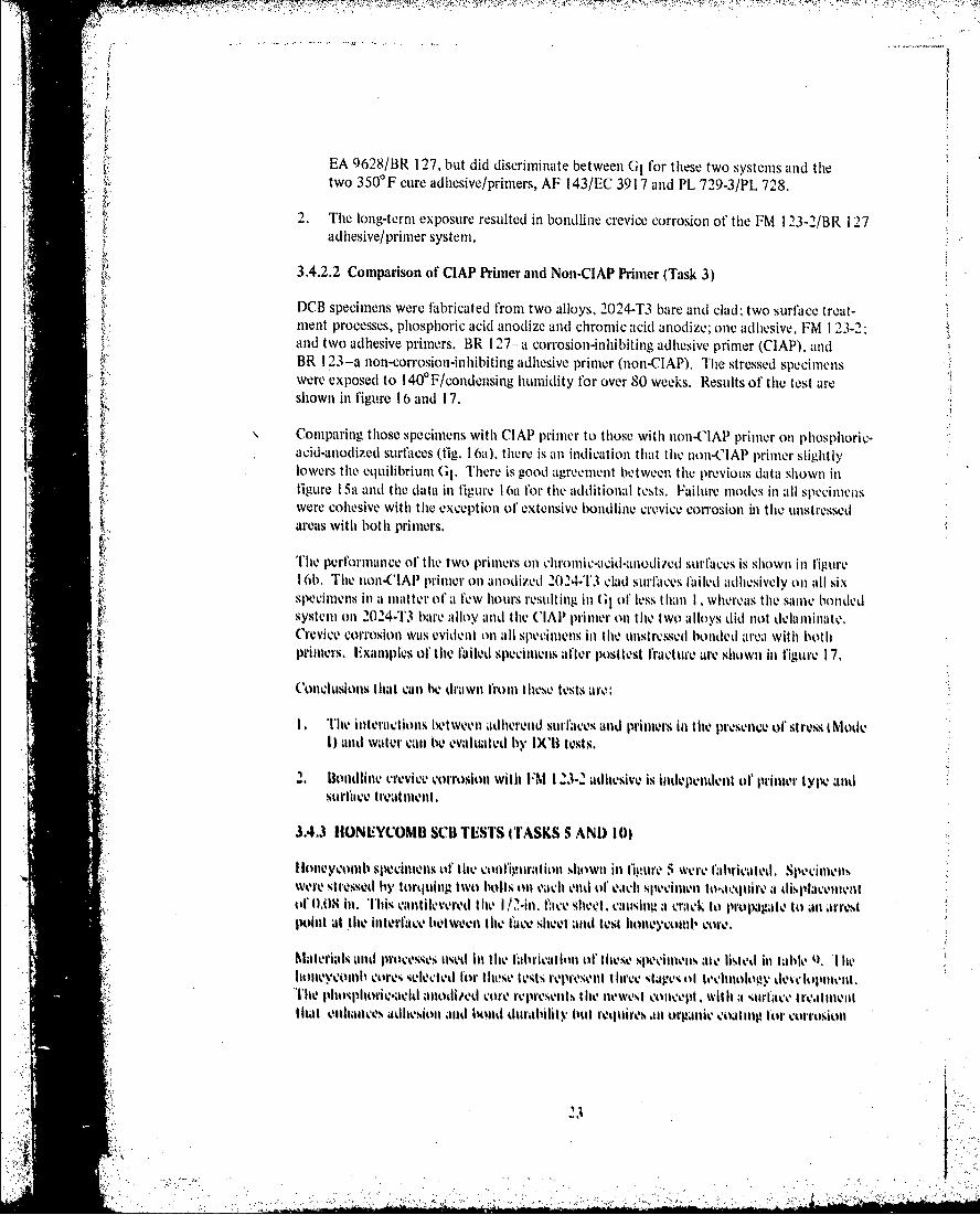
DCB specimens were fabricated fromn two alloys, 1014-T3 bare and clad; two surface treat-mnent processes, phosphoric acid anodize andl chromnic acid anodize; one adhiesive, FM 1 23-2.and two adhesive primers. BR 1 27-- a corrosion-inhibiting adhiesive primer (ClAPI), andBR 1 23-a non-corrosion-inhibiting adhesive primer (non-ClAPI). The stressed specimenswere exposed to 1400 F/condensing humidity for over 80 weeks. Results of the test areshown in figure 16 and 17.
Comparing those specimens with ClAP primcr to those with non-ClAPI primier onl phosphoric-acid-anodized surfaces (fig. 1 6a), there is an indication that the non-C1A1P primier slightly
lowes te euilbrim G. Tereis oodagreement between the previous data shiown intigure 1 5a and the dtat~a inl figure I 6a for the additional tests. Failure modes in all specimenswere cohiesive with the exception of extensive bondline crevice corrosion in the unstressedareas with both primecrs.
The performance of the two primiers on hoicai-aoie surf'aces is shown in figutreI 6b. Thie nion-('AIA primer onl anodiz.ed 2024-T'3 dlad surfkaces f~ailed adhesively on all sixspecimens inl a mlatter of a t'ew hours resulting in GI ol, less 1than1 1 . whereas the same bondedlsystem onl 2024-1T3 bare alloy and the ('lAP prinmer onl the two alloys did not delaminate.Crevice corrosion was evidenrt on all specimens inl the unstressed bonded areal with b1othIpr'imers. E.xamplvs ol' the failed specimiens after positest fracture are shown in figure 17.
{ (Conclusions that can he drawn troni these tests arc:
I ,The interactions between adhlerenda swrfaces and printiers inl thel pre!Senlce of stressi Modev1) and water canl Ibe evaIluted by IXiI tests.
.2. Borndfine crevice corrosion wvithi FM 123-1 adhiesive: is indepenldent 01' primer t ype andsurf~ace treat ment.
3.4.3 HIONEYCOMBI SO) TESTS ITASKS .5 AND) 10)
I loteveonlil spvecimnos ofl the collfiglraIt ion Shown inl lipuro 5 were fabiclated, S1100111011'were stressed by torquiaag two boIN on each enld of Veah Spievimenv to'-mctuire a displacenteniof OAS hi. ITWN cantilevered Itle I !2-in. face sheet, callsit a acrack o rpmte t JIi mr
phtat t11V hinertfmce between thei f~ace sheet and test hllonycoalut core.
hialerlals and lt)e ie sed inl the labtricalim ion ivIheesecmeis*me listed ill table Q~. 'I hiehonleycombil cores seletedti lor' these IteSt replre~sentl iluce stages ill technlolotly eLtpiem."The holoi-acid imnodied core represents% the newest eoncept 1. wit1 I4asutc t re4111umenltlmt nhamce adhesion *mnd bild ditraltihil but reqluires .11n orpaitic ýoat mug tot1 corrmosion
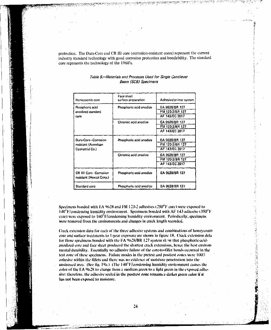
protection. The Dura-Core and CR III core (corrosion-resistant cores) represent the currentindustry standard technology with good corrosion protection and bondability. The standardcore represents the technology of the I 960's.
Table 9.-Materials and Processes Used for Single CantileverBeam (SCB) Specimens
Face sheetHoneycomb core surface preparation Adhesive/primer system
Phosphoric acid Phosphoric acid anodize EA 9628/BR 127anodized standard FM 123-2/BR 127core AF 143/EC 3917
Chromic acid anodize EA 9628/BR 127FM 123-2/BR 127AF 143/EC 3917
Dura-Core-Corrosion Phosphoric acid anodize EA 9628/BR 127resistant (American FM 123-2/BR 127Cyanamid Co.)_______ AF 143/EC 3917
Chromic acid anodize EA 9628/BR_127FM 123-2/BR 127AF 143/EC 3917
*CR III Core-~Corrosion Phosphoric acid anodize EA 9028/BR 127* resistant (Hexcel Corp.)
*Standard core Phosphoric acid anodize EA 9628/BR 12'/
Specimens hioided with E.A t)628and I~N 1 23-2 adhesives t 250'FPcure) were exposedI toI 40'1Pfcoitdensiiig humidity enviromnent. Specimens btonded with Al' 143 adhesive 1350'FP0111) Were exposkedi it) 1 (10' F/vonldensillkt hum~idity enio e .Periodically. spweclimelswere retinovvd fronm the envii'onnents andt citanges inl crack length recorded,
(Crack extelnsiol data for eacti oftilie three adhlesive systemls and coinhinlation% of, honleyconlitA.o0e 31nd surfiice t reatillulIts lto I -yellr exspostire tire sho~wni It figure IS., Crack C\Ieltesionl datafor tho~se splechnens bonded with lthe FA 96~28/I0( 1 27 systemn slu)w that phusphorlc-acid-aatodized core and fI'ce sheet pr-oduced tile shortest crack ex~tiasioiis. hencex the liest voiironl-mental durahlht v. hissentially no adhesive faihire o'tthe corv-to-flltet honds occurred inl tfitest zneoll tht lese speim-iens. Failure modes lin thle pretest and ptost test ofnes were I tillJ,,cohlesive withil lthe tillets and there was not evidlence of moisture penetration into ltheunt~rv-ssetl area. (S'ee fig, I 9a.) (The 1 40) P/odninghuiditily emmvirollnnvimm e~low.s thlecolor oft he E'A QIQ tot chane fromt a mnkedilimm green ito at light greenl inl tile podah-sive: tlmerefore. tile adhlesive seated ill tile pos4tlest toneC remniwams a dirket grevt color ifilhais nlot Well elposvil to Imoisture.
24

Specimens that had phosphori c-acid-anodi zed core and chromic-acid-anodized face sheetsproduced longer crack extensions but with the same failurm modes as with the precedingspecimens. Examination of the posttest area showed that either the crack had extendedfarther than the measured crack tip on one of the specimens or moisture had penetrated intothe cells of the posttest zone (fig. 1 9b).
The other EA 9628 bonded specimens representing combinations of standard core, Dura-Core, and CR Ill core, with the various face sheet surface preparations, exhibited 5 0% ormore adhesive failure of the core-to-fillet bond in the test zone. The standard core resultedin 100% adhesive failure and the longest crack extension. Examination of the EA 9628adhesive in the posttest zone of all the above combinations showed evidence of completemoisture penetration into this zone. Also, the failure modes in the posttest zone ranged upto 60% adhesive in core-to-fillet bonds. A typical example of the effect of moisture isshown in figure 1 9c, and a comparison of figure 1 9c with figures 1 9a and 1 9b illustrates thisobservation.
Crack extension data for those specimens bonded wvith the FM 123-2/BR11127 systemn showedthle core and face sheet combination of phosphoric acid anodize to have the shortest crackextension accompanied by almost 100% cohesive failure of the core-to-fillet bond. Thecombination of phiosphioric-acid-aniodized core and chromic-acid-anodized face sheets resultedin longer crack extensions, but with the same failure modes as thle phiosphioric-acid-anodizedcore and face sheets. There was nothing obviously different betweeni the two that wouldexplain the spread between the two sets of data. The combinations of Dura -Core withpliosplioric-aicitd-anodiizedI and chromic-acid-anodized face sheets resulted in about 50%adhesive failure of thle core-to-fillet bond in the test area, with slightly longer crackextensions than thle specimenls with phosphoric-acid-anodized core and face sheets.
cailLure modes in the posttest zone of all specimens bonded with FM 123.2 were 100%cohiesive in the fillet. Assessment otf moisture penetration into this area was not possiblesince IM 123-2 did not exhiibit any obvious color change resulting fromn exposure to 140'F/Icondensing humidity.
it A general observation of all S('l1specimniis bonded with tile I'M I23-2/BR 127 systemshowed that the adhesive fillets to tile cores were very small inuch smiallr than the filletsformned by te hi, A 9628/1111127 syswm. This mtay account for the longer initial cracklengths an1d thle tighter grouping of data of the I'M 1 23-2 bonded specimens compared to lthedata from~ tle ESA 9028 bonded specimens.
Crack extenision data for the sixecimens bonded with lthe AF 143/EW 391l7 system show verylittle spread betweenl thle differenit combinations of core andt face sheet surface. prepatrations.Assessment otfthe failure modes inl thle. test zone revealed that lthe specimnens with pltos it)ric-acikntollzed? core had about I 05 adhesive failure of lthe core-to-I illot bond. but thle spevi-mnlens with lDura.Core exhibited mlore than SW*, adheslive t'ulure of lthe core-to-billet bild.Failure nmoutivi inl the, postlest zonle of all specimenvis were 100" Cohesive, with% no evidence of'mioisture penietramtion iInto this area, At- 1 43 eliakiges color af'ter cxlk)sur- to 1 (0~ F/ conl-densing liumnidity. going from light brown to dArk browvn.
15
44I

A general comment relating to all the SCB3 specimens representing all three adhesives testedis that there were no instances of adhesive failure to any of the face sheets.
Conclusions to be drawn from this study are:
I . SCB specimens with phosphoric-acid-anodized standard core and face sheets exhibitedthe best environmental durability with all three adhesive systems tested.
2. The corrosion-resistant cores (Dura-Core and CR Ill core) were intermediate and thestandard core exhibited the poorest environmental durability with the 250' F cureadhesive systems tested.
3. The thick-adherend SCB specimen offers a senliquantitative and qualitative means ofassessing the stressed durability performance of hioneyconmb core adhesive face sheetbonds.
3.5 CYCLIC STRESS TESTS (TASKS 4 AND 8)
3.5.1 THICK-ADHEREND LAP-SHEAR CYCLIC LOAD TESTS
3.5.1 .1 Tests at 0.8 epli and 10 cpli (Task 4)
Thick-adherend lap-shear specimens were subjected to cyclic loading at two slowv frequenciesand four stress levels while exposed to 1 40' or I 600F/condensing humidity. TFie two cyclicload frequencies used are shown in figure 20. The Bell cycle. I hour at maximum loadtfll.,IX) and 1/4 hour at minimium load (f1n~11) was developed by the Bell lielicopter Company,l'ort worth, Texas (ref. 3). The Boeing cycle. 4 minutes at f~l. and 2 mlinutes tit flgpl. was,selected as a frequency thlat would be significantly fhaster than the Bell cycle, yet allowenoughi time for some polymer relaxation at fl and O 111i 1 fliland still lie compatible Withthe test equipment. The four stress levels of flnax were 1500. 1200. 4OO. and W~O psi, The11nijil stress equaled zero for aill cases. Thel% rate of' load application and releaso was ratherfast in all caws.s less thanl 2 seconlds front fill to 1`m10X.
"Filte test machine. shown In figure 2 1. functioned bly r.iigadlwrn edwihcantilevered onl a beamn. The test specdienvs were stressed individually Iin chambers that pro-
*vided colldemisingi humildity at thlt six-cified tempe1ratures.
These tests evaluiated L'A 0~628/111 127 and At' 143/1-'C 3417 ahse yem,2024-43clad and baire alumlinumil alloys, and phosphoric acid anodlize t IAC 5555) surc treatmntThe spe.cimens were exposed to 1400 IS/conden-ing humildity and I 601 F/condkenlsing Iwulidityfor the ESA 4028/11K 127 and AF- 143/tiC Sti 7 adhesive systiems, respetielly.
Data for those sp-cintacns Wronled witli the t-A 9)628/0tt 127 adhesive system and te-sted atithe two loadinig Irequenlleis are shown Ill table 10. D11411 fOr the specilimens bon1ded WithAF- 1143/ISV 34l7 adhesive system are shownIim latable 11 . The dawtaire presented as cyclesand tI me til failutre for those six-dilmtels t hat t'aikd or as residulalI shear strength at cumlulat IV,.eycles for those spochimens thW did not fail during; thw test period.

o ~ ~ c 1111 0~0) 0
c (V0 0
0 0 0 0 C0
m CD IfLnl
2 n (-n nL
in
3US
0h 00 o L
I- I-
A ___ ____ lii.to
271

b~~~ V i iiI cIl~
WA bgm, wtj C) LIM 0 - 0 C4-.C
CO iQ P* IMm0 ~ 000N
0c-c)'N N4 1
--- - -ERR
'a.o 0
CJ X
inn
'SS
CO .c
a'
a ux
OhO Aq

Failure modes of all specimens were 100% cohesive in the center of the bondline, as shownin figure 22. Several specimens fabricated with 2024-T3 clad alloy had some crevicecorrosion undercutting the bondline of both adhesives (e.g., fig. 22a); however, the amountof corrosion apparently did not affect the time-to-failure data. The same filiform corrosionphenomenon was observed in the bondlines of DCB specimens bonded with FM 123-2/BR 127 adhesive system after extended exposure to 1400F/condensing humidity, as reportedin sections 3.2.2 and 3.4.2.
A summary of the failure data of tables 10 and II is shown in figure 23. 'This shows thespread between the failures at 0.8 and 10 cph for the two adhesive systems, The slower Bellcycle, 0.8 cph, is much more damaging than the faster l0-cph cycle. Failures occurred onlyat 1500 psi with the AF 143/EC 3917 system tested at 0.8 and 10 cph. This comparisonwith the EA 9628/BR 1127 system demonstrates the improved stressed durability characteris-tics of the 350'F curing AF 143.
The following conclusions may be drawn:
1. The slow Bell cycle, 0.8 cph, is more damaging per cycle for the two adhesive systemstested than is the I O-cph Boeing cycle.
2. The AF 143/EC 3917 adhesive system is more durable in cyclic tests than the EA 9628/BR 127 adhesive system.
3. Cyclic loading produces failures much faster than does static load testing.
3.S.1.2 Tests at 1800 cpm (Task 8)
The thick.adherend lap-shear specimens used I this series of tests dilTered only in llhat tileends of the specimens were not notched, which facilitated mounting in the SF-I -UWiedemann Baldwin fatitgue machines. All tests were run at 1800 cpm tit a stress ratio. R,of 0.00 (R i Maximlumu strsses, fula; ranged fromt 2000 to 3300 psi, Spedi-nens were tested in lour environmenits: 7VFIlaborator, hnmidity T20% to 30)( 75" FIwet. 1401-'/dry (less than I 0%). and 1400 F/wet. Spteci1ns were not prvcondilloned beforelesting Il the wet en1vironmelnlts.
* : Specimens testled in the trur ellvironments were 2024:13 bare alloy bonded with Ihe It:A
9618/1R 127 akdlesiw system. Two surface trealtuents were incorpotrated: phosphlricacid atiodize (BAV $555) and chromic acid atuodine (Hell process). Additional speci11ens of70754T6 bare alloy using the same adhesive and surface propioratlolls were tested I1n the
* . I. 140°F/wet evironmunt.
wThe speeiloon Urrallgelitellt ti the SFI.I V fatligue nlaclnue wit Ih tile chambtler for prodlucilpthe f40ourwel onvironment surromitinog ithe spetiten is shown ill figture '4. The test restiltsfor, l the four otviromt alllld , lspociolvl cmn llbillatlims are shlowil ill figure 25. Ifigh st %6levels were iu-ed to d-velop tlhe S.N curves within reammable timle piriorls., Comparing Itlse.dztak willi the slow c-yclc data of figure 23 shows that far ls damtlage. uccur e l e at1800 puII thali at the slow cyclic ratls.
it 2'i
I ;,.

F'ailure modes are different when compared to the slow cyclic rates, as shown in figures 26and 27. The fingernail-shaped area is the crack front that propagates from the load transferedge until the remaining bond fails. The failure mode within the fingernail area is very near
li tically shown in figure 26a. This failure mode is different from those observed with the slowcycle tests, which wvere all in the center of thle bond suggesting a creep-rupture-type failure.The fast-cycle fatigue-hiduced failure shows evidence of what could be termed fatiguestriations (fig. 28).
Some of' thle specimens that were chromic acid anodized failed early. (See figs. 25b and 25e.)These specimens wvere characterized by a different failure mode (fig. 26b). Inl these cases,the fingerntail-shaped area had substantial areas of ant oxide-oriented failure.
Conclusions drawn front these tests are:
I1. 1ile high-Irequlency cyclic load tests. 1 800 epmn, arc much less damatging to the bondineper cycle thant thle low-frequency tests.
2. Bonds to comcci-niedsurfaces reult inl occasional oxide failures at tile stresslevels and cyclic toad freoquency used.
3.~ ~ 11 Anraigtets temlperature from~ 759 to 10 FOi shorteons t he fatigue lift: of thebondeod systems tested. Thle presence or absenlceor ('Watter dlid not seemn to have anleffect tit either ltemperatutre. T I'tetst duration wash less that) 2 days. possibly notallowing sufficienlt time for thle watlr to affeet I th Ilechanlical prOperiM! of thleadhesive. Had specvimlens been Preconditioned to a mois6ture: equilibrium cowiditiuon.
resuts mght ave bveen differvnt .)
4. Failure modes suggest it fitilgie Mailue of thet adhiesive ait or near the deicplrhiterfaice. Ill Contrast, thle slow cyclic tests. 0,A and 10 Cph. suggiest a creep-rupt ure-type failure Where thle failuire Is entfirely In tile centler of thle biond. There was nto evidnclicthlat phosphori acid alodilied stirfaces a1Vrel influenolced lithe fitigue behlavior of lUPsheaor spwecimen'.s. However, there was sonicl evidencev that cliromlill ci~d 11no0dizedsuirfaces did linfluence thle siveillmen fatigue behavior. whell t-ested at 1$0U0 cplli. ssonicosixe611nens witl) cliromici acid andzdsurftaces oxvlblited decrases Ill futigaue Mleapparently us a resuilt of O.'dde-nlitilted failuros.
3.5.2- TIIICIK.ADH'RUND DOI CVCLIC WOAD TESTS (TASKI~
"I* Tilodick udh led OC li seclimens, %Vote stressett undler c-yclic loads bly al1ternlating thle displave-*lol muet atil Ithe lo points1 Iromi 0 to 0.-1 Inl. 'hi acquilyl tile dlynamlic Osp-ets t.f cyclic loading..
delvi'sls were psinned thlroutgh t1 Iteind of Ithe speclilown% ttsing I N4-ill pll-, ilmrstca of tI~ 11.4loited,imolls showit ill figureo 3. Tlids toadilvi arraniwunentl is Shtowvtn Il igmures N.' aUll 30 mo the'w soditloeo'lm test1 i~alw kwtusue.
spevilllelts Wine calricated of 02412 3 ntd 7075-1f't love alliutiklkil phy~~llosphoricacd nudlchOtmnici acido allodize. anl F111L otchli race Vraiemt:ad)A 0h2-01111127
Adwl e lple. 1101de04 'jkiotnea comasistiag of 2024.'h'3 Wire allay sutrlitv troultod wih
.101
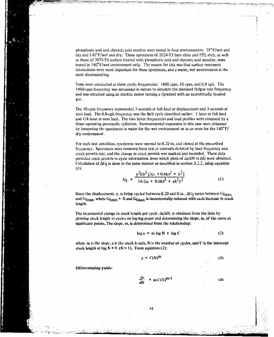
phosphoric acid and chromic; acid anodize were tested in four environments: 750 F/wet anddry and 1 400 F/wet and dry. Those specimens of 2024-T3 bare alloy and FPL etch, as wellas those of 7075-T6 surface treated with phosphoric acid and chromic acid anodize, weretested in 140'F/wet environment only. The reason for this was that surface treatmentinteractions were most important for these specimens, and a warm, wet environment is themost discriminating.
Tests were conducted at three cyclic frequencies: 1800 cpm, 10 cpm, and 0.8 cph. TheI 800-cpii frequency was sinusoidal in nature to simulate the standard fatigue test frequencyand was obtained using an electric motor turning a flywheel with an eccentrically locatedPinl.
The lO-cpmn frequency represented 3 seconds at full load or displacement and 3 seconds atzero load. The 0.8-cph frequency was the Bell cycle described earlier: I hour at full loadand 114 hour at zero load. The two latter frequencies and load profiles were obtained by atimter operating pneumatic cylinders. Environmental exposures in this case wvere obtainedby immersing. the specimens in water for the wet environmncit or inl anl oven for the 140'F/dry environment.
For each test condition, specimens were opened to 0.20 in. and closed at the prescribedfrequency. Specimens were removed from test at intervals dictated by load frequency andcrack growth rate. and the change in crack growth was marked and recorded, These dataprovided crack growth vs cycle information trom wvhich plots of da/dN vs AG were obtained.Calculation of AGj is dono in the sinie manner as descrihed in section 3.2.2. using equation
y2 uh3 13(a 40,6102 + 121J () 16(U + 0.(I)11) + alt2 1 2 l
Since lthe islc en.Y. is being cycled between 0.20 and 0 hin,. A(;1 varies betwoeen Glntaxt,and Gt111jill. WlwreI GIJ,11 r,1 0 and Glutax is invrementally reduced with euAch itivrease in cracklength.
Theo hivremental ctIiqune inl crack length per cycle. da/dN. is obtained from lthe data byplotting crack longth vi cycles on log-log paper and dotermining lthe slope. tit, of the curve atsignitivant points. Tito slope, tit. 6s determinted from lthe rolationship:
tog a tita log N +' lug C (2)
When, titiis lthe 'lopc. a irlithe Crack lu~igth. N i-. lite nwolter of cycles. and C is lthe Intercept
crack entgth at log N 0 I N I. Vtont etjuation 0 ):
t~iftcren ftt QN01 yted
.t41
dN. .. .

Then da/dN is determined from equation (4) and plotted vs AG1 on log-log paper.
* ~The results for the different alloy, surface treatment, cyclic frequency, and environment
combinations are shown in figure 31 . From the I 800-cpm frequtency tests, it was possibleto determine a threshold point, AGITH, which is that point at which a crack no longerpropagates.
Thle plots show characteristic S-shaped curves. This shape is also typical for monolithicmetallic materials. In these curves, the uipper right-hand section of the curve (i.e., high AG1and high crack growth rate) represents the point where the initial crack is generated in thespecimen and it comecs to some arrest point, Gla, at zero cycles.
As the load is reduced to y = 0 and back to Yniax =0.20 in. the crack will move forward bysome incremental amiount. With each cycle, Gima,,x becomes less as the crack grows until thecrack growth per cycle approaches zero or AGITH, which is represented by the bottom !eftportion of the curves, Glniiil is equal to zero in all tests.
In all of' the tests run at 1800 cpmi, a threshold was established which was between a AG1Iof 1,.0 to 1.5 for tests run at -roomn temperature/dry and wet, and between a AGI of 0.5and 0.75 for tests run at I 40'F/dry' and wet.
The tests run at 10 cpmi were in general agreement with the I 800-Cpmn curves. However.thresholds were not established ait 10 epil because of timle Constraints.
The test run at 0.8 cph prodluced longer cracks per cycle than either or' the faster cyclic ratesat the samie A(;1. Less, data were collveted fot, these'tests because of the very slow cycle andthe long test tillws involved. In all the plots of(WA/dN vs AW. the response in flitigue followed
L trenlds similar to those observed by Nios'tovoy and Ripling for bonded joints (ref'. 4). eventhough Niostovoy used it different spevimien configuration, ats well as a different mlethod. oh'obtainling data. Iiis thresholdl A61-1-jj values ranged fromt 0.3 to 2,8 in-lh/in 2 for'severaldifferent commercial adhesives tvsted lit several enivironmenlti. as comlpared to 0.3 to 1.0for FA 962'8 tested lin this program. -
Failure mlodes, with few exceptions. were 1001,/ coheivii-. tfiltire Tile da/dN plots arc there-fore rersnaieof adhe-ive propertiestind not system prope-rties, Figure 32 shiowstypical fitilure mtitode for several euvironments. load freqjuencies. an:d bonded systems. Twoexceptioiqn atV noted:
I One of the cr iead'ni spwecimiens showed a rapid drop In vrack cntaninclitcapability (AGI of 0,6.0 h!1 2 hc having readied an apparen AG;I1'h1 oh aboiit 1 .5wh01r1 dcrc"got Ma cure tg 32~lt. 1. FxAniilation of thev fkatiures -hwd adhiesive or intra-oxide ttilutro ill the area
2. Another cIrmc atidnoldited %pocimenvi e,ýluil'ivkd t he sae dhecsive lI" flure Inl thetitle area oft the spxeimen Ifig. 32c , 1howevet, ill this case 1t101c wai no obviotit
inlcrea-e ill crack growith rate or decrease Ino AG1-Ij'1 dueo to this dutnlge ill (Wallure niodo.
32i
2-I~
Conclusions that may be drawn from these tests are.
I1. Cyclic loading of DCB specimens is more damaging to the stressed bondline than isstatic stress loading at the same stress level.
2. There is a threshold level, AGITH, at which the crack no longer propagates; AGITH at140OF is 0.5 to 0.75, which is about half of AGITH at 75,3F (1.0 to 1.6) for the adhesive
V system examined.
3. The Bell cycle (0.8 cph) is more damaging per cycle than the 10 and I 800-cpm cyclicrates.
i{4. Testing hi a water environment at 750 or 140'F, without preconditioning of the speci-mens, produced the same results as dry conditions for the test durations involved.
5. The test method is of value in that it can identify a property of an adhesive, AGITH,which relates to its behavior under dynamic loading.
6. Theo magnitude of AGITH for the adhesive tested is in the same range as that observedfor aluminum alloys.
7. Theewsn vdneta hý
GlTH- appurently us a ro-ult of oxide-initiated failures.
.4 ~The purpose of this task wvas to identify tile offects of a very corrosive environmerit on bond-lines o)f different bonded syses These system variutions included clad arid bare alloys,%suirface trvatmeriets. adhesive Primhers. arld adhevsives. The variouls combinatiIonls aire shown illtable 12. Tilte. t Vp~ie onifiguration used for thes- tests is shown in figure 4.
Tab/v 12.-Bondrnont Variables for Sol vpa Tests
Surface trQam1Alloys Adiiiiive/pfiftler %V61011
Phosliiorlc acid atodlltt 202443 wad FM 123-2/BR 127_______FM 123,2/811123
Chton'k acid ariodise 15A 028I9R 127
2024-T3 b.&to FM 12312/811 127FPL otdi FM 1?32/12) 123
UA 062810HI 1277071'TO VIdI A 96201311t3 127
11-17616 itais EA 062W8l34 12?
U.

Five specimens were fabricated for each of the bonded systems. The specimens were thenplaced in a salt spray environment of 5% NaCI at 950 F. The change in crack length of eachspecimen was recorded periodically. At the end of I month, one specimen was randomlyselected from each bonded system and opened for visual inspection of the bondline conditionboth in the stressed zone (crack tip zone) and in the unstressed zone. This same procedure
was carried out after 2, 3, 6, and 1 2 months when the last specimen was removed from test.
The average crack lengths and the bondline appearance at the end of each time period areshown in tables 13, 14, and 15, and figure 33. The data in the tables are the averages offive wedge specimens for intervals to 30 days and the averages of the remaining specimensfor each interval thereafter. This procedure sometimes resulted in a decrease in the averagecrack length.
Two basic differences in durability of the bonded systemns tested were apparent in these tests.First, the crack growth data showed that some of the bonded systems resulted inl poorstressed durability performance as characterized by large crack growths after relatively shortexposure times (I to 30 days). These specimens also showved adhesive failure modes in the
* ~crack growth zone. These systems were (1) the FM I 23-2/BR 1 23 system bonded to 2024-T3clad and bare alloys which were chromici acid anodized or FIPL etched, and (2) the EA 9628/BR127 system bonded to chromnic-acid-aniodized 2024-T3 clad alloy and FPL etchled 7075-T6clad alloy.
Trhe second basic difference in durability performance was% the corrosion phenomenon whichoccurredl randomly in the bondline. stressed or unstressed. starting at an edlge-, This differencewas not apparent in the crack growth ratQ dlata. The crevice corrosion was diominated by claddissolution because of the sacrilicial niatutre of cladding, Althoughi bondline crevice corrosion
* occuirred In till the clad alloy bonded systems tested, the prebond surface treatmnirt has a
dfnthe efetni the progress of clad. dissolution, i.e.. th& anodlize surfamce tre~atments retardtiedisolutionl rate significantly. which Is pairticularly true in those systemq that uise IlkI 27
(ClAP) printer. The phosphoric acid ariodize jperfortied Algltly better thtan the clironticeacid allodize In this regard.
Rl)(ond1ne creviceý corrosionl Wall' also evident withi the' bare alloys. bill to a far lesser deg.trev*tan with) thle clald alloys. Most boindhnle corrosiono ae mly occurred Withi those: thlatwere I'PL etched, and was more pronouinced onl 7075:1T0 bare. There was essentially nobonldflne crevice corrosion of' bare alloys t ha I were phosphoric aceid anlodbovih.
Conclusions that Canl be dratwn front these results 31v ts, follows:
Tlhe phosphoric: acid amnotlee procesg provides markedly Improved siressed bond oIntIdurability and retards bondlint: creice corrosion in severely eortosive enivironmen'oltswheati comtparedl to two other stt~'teatsurf~ace prepa ration procosso%.
S2.rk:%%ed bondi joint dutribility is markedly Aflecied by thev adhevromd probond suirhacetretmntan te dhsive/primer sytell InI conitact Willh it, Thisk I, evidonced by Ithe
* . j~~~~por petrnneof FNI 1 32~I 123 wotnoClAP) adliesivc~lim-ler systemt on V'.etchled and cr ica Ilk Iod iive 2024-Tl3 clad aml id m!r and the better perIfmrmagactOf 1the saite systens when it l 1.27 (ClAP) I,. sutktitnmted bor lil 1.23 (iton-ClAP).
34
ýA4

rl ( (R0L
co~
+ -) 0( (0 (0)N CV0)
'o a to cno (D LZ
U Lq 'I~t U LD V: ulL
MIT
+ f, m.. om n0
Al
+ 'D C) 'q N N
MONN
Czu~
f *"

0 W 'I (Rcv ceq i -: ' OR
coC ooCOCV) N Lf)w 0 0
N~ C v - 'CO - CNC' -
oLO)
"C3 + N 0-' COc (Dc Ln 00
(Vo )- CN -.- CN
a. oco N~c Y CY)0) r*
m~ cqC vi 'i rCN LO
+ cow ( 0 ()q
m q
co w , U
u.
N2 N'C% (NN NN %- co ~coc'
co
U. U.0.4 411

0 0 0 0' N C(Dc u N
C'. c c
0 '~o ~~TO) O CO* O
L~>
(0y0 (00 0- v CO
(V M F- - -CN c
If' I. (V >
'0 t m m~ OD O CJ 00+ O to to L C
+ LO CN O
0 3 U -k tR t cq
iý i
EfN L('-cv)j*
Nz ~ - --1~ I ->
Vm
+ M '( CJ'4 %N 1%
4 LO( Ln L (R (4F%
0. 0mw
C337
m

3. The wedge test mnethod is discriminating and provides a relative ranking for many ofthe parameters that affect bond joint durability.
4. The data confirm that clad alulminum11 in thle bondlines is undesirable under severely
corrosive conditions.
3.7 LAB TEST/INSER VICE CORRELATION (TASK 7)
The purpose of this task was to attempt to establish a correlation between test results derivedfrom labora tory-pre pared specimens andl service performance. Two groups of bonded aircraftdetails were used in this study. The first group was from commricti~al aircraft and the secondfrom Air Force aircraft. Most of the details employed in this study had demonstrated poorbond durability resulting from service operations-, i.e., bondlines had varying degrees ofdelamnination and corrosion. Test specimens were fabricated from those areas of the bondeddetails where the original bond was still intact.
3.7.1 DURABILITY TESTING OF COMMERCIAL AIRCRAFT
Details consisting of metal-to-mnetal bonds representing skin, doubler. and triplet' configura-tions from four commtiercial aircraft were examined in thle first part of this task. They wereidentified as aircraft A, B, C,. and 1), where aircraft A and C' had delamnination and varyingdegrees ot corrosion. and aircraft B and 1) had panels that did not exhibit any bond problemsinl service. Fracture tests (Wedge type), Ia p-shear tests (ssands esadroomi-tempera t tire
cotrls. ora-her essand peel tests were Conducted Oil specimeins prepared from these
bonded details.
Table I 6 lists thle materials of each aircraf't detail. the total flight-hours accullulaed at thletinite of' removal fr'om the aircral't. and the visual con~dition of' thle detail,
Table 16.-C~ormmrcial Aircraft Bonidedl Details
Aircraft Alloy Surface l~hAicat Aly pro;liratioii Adltosivlvo/prnr Flgh hours Conilillnts
A 2024,T3 FPL etch AF 126/EC 2320 9000* Etensivia (flaillhithti#Jl ofclad skin'(oubtor bond, Some In
doubler -trilejt build. Mild
a 20244T3 FPL atch AF 126/EC 2.120 5M+0 No bond doetiniattoo orclad corrowion.
C 202443 FPL utch FM 123-21613 1123 9000' Exteosive delamliiitior, (if
- Clad Ltofrosionl,
' I f

Specimen configurations for thle specific tests for each aircraft are shown inl figures 34through 37. Specimen configurations varied from the standard test specimen configurationsdepending on detail configurations and whether or not stiffening doublers were required forspecimen symmetry. In those cases where stiffening doublers were used, the doublers werebonded to thle aircraft details as wide-area bonds using a 2500'F cure modified epoxy, andtile test specimens were then cut to the configuration shown.
Table 1 7 presents results of lap-shear, porta-shear, peel and wedge tests for the aircraft details,along wvith a description of the associated failure modes. Even though the details from twoaircraft had exhibited delamination in service, thle conventional test results indicated that theremaining bonded areas were still acceptable in terms of mechanical properties.
Timne-to-failure results of stressed lap-shear specimens machined from details of aircraft Aand B are shown in figure 38. The test results do not predict the inservice performance ofeither structure, since the two details fromn aircraft A had experienced delamination inservice and the two from aircraft B had not.
The wvedge test results for these two aircraft, shown in figure 39 clearly show that aircraft Bhad a more durable bond. (Note, however, that the wvedge test specimen configuration isdifferent between thle skin-doubler bond and the doubler-tripler bond, and between aircraftA and B. figs. 34 and 35, which accounts for the difference in initial crack lengths.) Thespecimen configurations tire nonconventional and thle results cannot be compared onl a one-to-one basis with result,, from conventional wedge test specimen conlfigurat ions.
A bonded mnetal-to-mectal section cut from aircraft C detail is shown in figure 40. The photoidentifies the areas where various tests were conducted, as well as an area where delamninationand corrosion occurred,
Tile panIel wvas first in-spectd using ultras-onic through-transmnission O-scan to confirm tl~eboundaries ofdlmnto.Next, an cloct roilyna mic proof load test to 2000 psi was con-
* ducted in an area adjaceqil to tile dehaintiation and in another ale a well away. Porta-shieartests were conducted in and around the doughnlut-shaped prool-loaded areas%. as well as atl
*other randoim spiots onl tile Panel. The large areas for wedge test specimens and peel spci-Ilens were cut front tile Ininlel andl appropriate doublevs bondled to one or both siides. as
iv"' shown inl figure 36. Test spveimens were then cut froin these areas as indicated.
Pot-shear and peel resuilts tire shown in table l17 and wvdgc test results are shown in figure41 . A typical wedge test specimen and a typical p~eel test specilimen after %vompletionl of testingare shown inl figure 42. ~Thle wedge test %Ipecimen -Xhihlted cohlesive faiture inl thle pretest andliosthest fractulre ;.ove". whereas !it the test area extem'nSiV lle ahsive fuiture occurred. With thetsmrticillar specilntel shown, the porta-shevar button whichl had first seeni a 2000-psi proot, toadfollowed by thle 51lOU-psi porla-Nluelr attermp~t withjout failing has easily delaminatied un1derthle comlbinlationl of Ntiess and I 2OW'F/eoiltdelsingp humilidity enlvi ronmlienlt. The peel speci mell
exhibied exclvlen peel Strenugthu Plus I OW4 Cohesive raiuire. Htowever, whenl water wasilltrodulced al tile buuudflise. thle failuire himmediately went it)tile intevrface, anld adhiesive

.~0LL E < 0 4 0
CNN
rrlLn 00 I II*1i
coc coN O 0co mz~0 -n 0 D- T-i
M0 N 0 C
b i 0 tn0i ' (I Ci
o0 0a cS
tn 0.
4)4
in mo n
(40
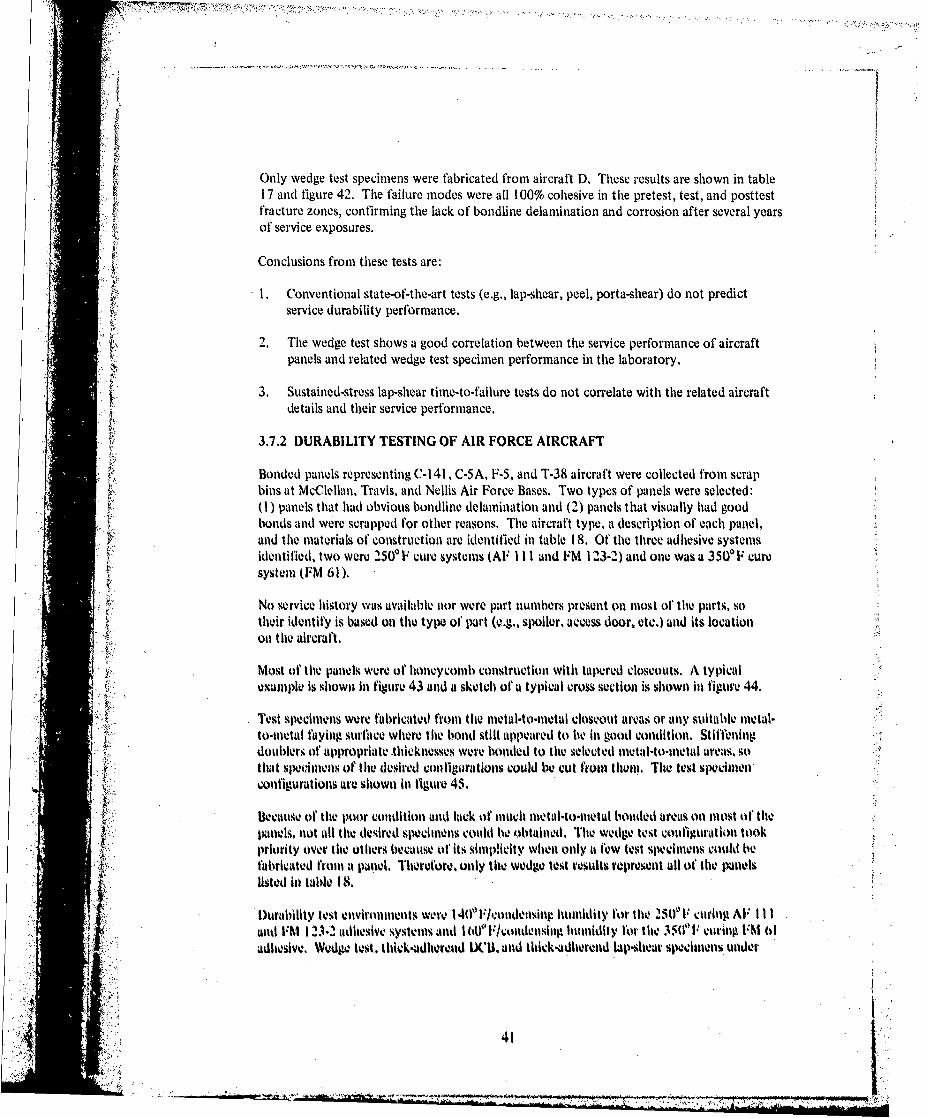
Only wedge test specimens were fabricated from aircraft D, These results are shown in table17 and figure 42. The failure modes were all 100% cohesive in thle pretest, test, and posttest
P ftracture zones, confirming the lack of bondfine delamination and corrosion after several yearsV of service exposures.
Conclusions from these tests are:
1 . Conventional state-of-the-art tests (e.g., lap-shear, peel, porta-shear) do not predictservice durability performance.
2. The wedge test shows a good correlation between the service performance of aircraftpanels and related wedge test specimen performance in the laboratory.
3. Sustained-stress lap-shear timne-to-failure tests do not correlate with the related aircraftdetails and their service performance.
3.7.2 DURABILITY TESTING OF AIR FORCE AIRCRAFT
Bonded panels representing C-I 41 , C-5A, F-5, and T-38 aircraft were collected from scrapbinls at McClellan, Travis, and Nellis Air Force Bases. Two types of panels were selected:(1) panels that had obvious bondline delamnination and (2) panels that visually had goodbonds and were scrapped for other reasons. The aircraft type, a description of each panel,and tile materials of construction are identified in table 1 8. Ofthe three adhesive systemsidentified. two were 25OPF cure systems (AF I111 and FM 12-3-2) and one was a 350'F curesystem (FM 61)
No service history was available iior were part numbers present onl most of' thet. parts, sotheir identify is based on the type of purtle~. spoiler, access door. etc.) and its locationoi the aircraft.
Most of thle panlels, were of hioneycomlb construction with taperedl closeouts. A typical
14 example is showni in figure 43 and a sketch of a typical cross section is shown it) figure 44.
Test specimens were fabricated from (lhe metul-to-metul closeout arva. or any suitable metal-to-mletal faying surfaice where thle bonld still appeared to tie ill good condition. stiffenlingdoublers olt' ppropriate Ahtlickne.,sses8 were bonided to thle Selected mletal-to-muetall areas, so0thiat specimens of thle desired configurations could be cut. froil the011, Thle test specvilimenconfigurations are shiown Wn figure 45.
* Becaus-e of the poor condition and tack of much metal-to-metal bionded areas onl most of~thepalnels, not all tile desired spiecimens could lie obtained, 'Fie wedge test configuration tookpriority over tile others because of its simiplicity wheni Only a few test spechimens could lie
*fabricated froml at panel. Therefore, onlly tile wedge. test rosults ropresenit all of thev Panelslisted Ill table M t
Durability test eliviromnilents were I 40 F/a.ondensitip humidity for thle 25ff1' curhig AV IlIl
adhiesive. Wedge test. thidk-udhieread 00C, and thick-adhivrend hap-m-lieur specinienis under
4 41

.4.
0 0.0 0 ~ (V (
C L 0L 0 C m.0 .0o.
4 0 0 0 0o 0~(
(V~ 0 0G
m '4 .- V4V
(V 0 0 B~ 2
~0. .2~
CCD0 0 V 0 .
0 00(3 C a z z
0)l
- LLL U.Lu U . U
ca)
0
a) Q)Cfl0. 0... a
a) cc cni'a)a
(0 c c
CMex r a & r-
t ~ ~ 5 3 Z 0
I-
knI
....... 2

sustained stresses were exposed to these environments. The sustained-stress level for lap-shearspecimens was 1 500 psi. Climbing drum peel and thick-adherend lap-shear specimens forresidual bond strengths were conducted at room temperature.
Room-temperature climbing drum peel and thick-adherend lap-shear results are shown illtable 1 9. The peel results for AF Ill are variable, which is characteristic of AF Ill1. Thlelowest strength of 42 in-lb/in suggests a possible durability problem with tile wing panel.This was verified in the wedge test results where extensive crack extension occurred(fig. 46a).
Table 19.--Residual Room Temperature Peel and Shear Strength-Air Force Aircraft Bondments
Peel ShearAdhesiye strength3, strengtha,
Aircraft Part description system in.-lb/in. psi
C-141 Upper wing panel outboard of AF 111 78 C24 20life raft _______ _______
U~pper wing canal 1 AF I1ll7 02186Upper wing life raft door AF 111 144 -7 2440Wing panel AF ill 42 0242Upper wing access door AF Ill 12 1730
P-6 Outboard trailing edge 1 FM 61 12 1078Outboard trailing edge 2 FM 61 -- 1960
T-38 Outboard wing trailing edge FM 01 9 4766
C.BA Aileron closeout door FM -23,2 boo 019200 Specrnenrepliatio__s
OSpeclmon replication Is I2
CM01at failure
* INM 01 typically 1itiI low pitlt- ela l streitgills. bilt the 1) and 12 inllb1itt1 Values areabouiti half of typical. Tile average peel of 60( for lthe I~N 1-13-2 Is itorinal for this Itullie.rlal.
%Vedge test resulits for At, I I I bontdmen1% tire shown hi 11igures 4Wa Mud 46h, The low d~tra-Wllhy re~silts. figure 4(ibimtrellate well Willi theV paliel Coliditioll 51114' dislitid was cvidellt,The wedge test crack growth area WHIMe adhiesively.
Thew restilts shiownt in figure 4bva toit) ot correlate os wvell %ince tile crack emtensiots. ofsixeltliet1s lroni 1itw whig p'anel alkid uppe~r Wing lilerall dloor inkficat thatt p~ot.r servic ejr-foiltuivuae could 1 bexetd 1ow4eVer, tile paliels. Iad lltl yet di~tiolldot Ill service.
43'

Specimens from the third panel (tipper wing panel between 5 and 6 spoilers) showed marginalbut slow crack extension over the test period, which may show a correlation with itssatisfactory service performance to the time of panel removal. All specimens exhibitedadhesive failure in the test area.
Wedge test results for those details that were bonded with thle FM 61 adhesive are shown infigure 46c. The one detail from the T-38 had evidence of delamnination and corrosion in themetal-to-mietal bonded areas, and the wedge test specimens correlated well with thle poorbond durability in service. Thle two F-5 trailing edge details had no apparent bond serviceproblems, and the wedge test results showed a marked improvement in bond durability ascompared to the T-38 detail. This difterence must account for the differences in servicedurability performance. Thle f'ailure modes in the Aa crack growth zone for thle F-S speci-miens were adhesive, however --an undesirable condition. The relative inservice timies forthese components are not known.
Wedge test results from a C-SA detail andi a T-38 detail bonded wvith FM 1 23-2 adhesive tireshowvn in figure 46d. The C-SA detail appeared to have never been onl an airplane and had nobond delamination, whereas the '[-38 detail had obviously been in service but had no bonddelamination. Thle wedge test results indicated that both details should have inadequateservice durability.
Sustained-stress lap-shear results for those details bonded with AF Ill and FM 61 adhesivesare shown inl figure 47. A correlation between lthe as-received detail condition. wedge testresults. and the results shown in figureý 47 is not obvious. Large voids were present in thlespeclimenl from thle wing p~anel detail, possibly causing early failure of the lap-shear specimen,Only one specimen represents each of the aircraft details: therefore. there is no indication of.scatter for each, Bused onl the sustained-stress results presented inl sections 3,2.1 and 3.4.1.onle would normally expect conlsiderable scatter. lIn comparing lthe FM 61 adhiesive %ustained-streiss sheur results to lthe respective wedge test results,, there seemsi to lit a consistent trend:however, the qjuestion of' scatter would be Present here also. 'rte failure mlode would IVlthe best indicator. This was the situation Wilit lthe tust results from thev coinmiercia~l airplane(see. 3.7.1)
Thick-adhierend DIWO test results tire shown inl table 20 Tl'c esuilts aire expressed inl terms ofGI. strain eniergy release rate. For thle AF Ill adhes iethe initial ~crack lengith varied cont-sidertibly, resultilig inl GI inlitia! values between 18 mid 1.7 hn-lbhitr. It Seems to be at charac-
tens~e ofthisAdhsve system tat a broad range ot( t a values is produced. A value of .1 8hi-lb/lin- I% near but less thani (,,. whereas I1.7 in-lb/ini2 I-s tit or niejr tile lotwer boundjis 1Upon exposulre ito I 4ti-cotidensllpg Iluinlidity. GIl dropped to relatively low values. conlsistent1
*Witlit tile Wedge test resudts. Thew lirge variation in GI,, may Ne inl pat acracterkstic ofAF Il 11 us deonstotrated inl th10 variable lkeel results shown ill tablek I19.
IX 'U secillmeis Withi IFM (it adlicsive aplit YWIldedj results coniwStent Witli the detail uondition41nd lthe Wedge test rsults,
*1 44

(N
0N cO i- O
(n 00- 04 -
0 C
C) 0 04)u
oo(4 U,
0N -0 ON m m
v 0; -O O(N Q
II N - O
LflL
(o u ~ c
-L W

* 'Conclusions are as follows:
• 1. Conventional state-of-the-art tests (e.g., lap-shear, peel, porta-shear) do not predictservice durability performance.
2. The Mode I fracture tests (i.e., wedge test and DCB test) show a reasonable correlationbetween service panels that have delaminated interfacially (adhesive failure) and poortest specimen exposure performance.
3. Sustained-stress lap-shear tests do not correlate well with the related aircraft detail andits service performance.
4o
.11
.4..
• . .
. -. I::~ .* ... .

4.0 PHASE IV, SPECIMENS FOR OUTDOOR EXPOSURE
The purpose of Phase IV was to use the information generated in this program to providetest specimens representing the most durable bonded metal-to-metal and sandwich construc-tion for Air Force use. These specimens are to be tested by the Air Force in long-termoutdoor testing at locations to be determined.
The materials and processes selected for the Phase IV specimens and bonded panels areshown in table 21.
Table 21.-Miterials and Processes for Phase 1V Specimens
Adherends Surface preparation Core material Adhesive/primer
2024.T3 bare Phosphoric acid anodize Phosphoric acid 2500 F Cureper Boeing process anodize and/or EA 9628/BR 127specification BAG 5555 DuraCore/CR III core
350 F CureAF 143/EC 3917
47
A• ; - - •" -L

5.0 DISCUSSION
The preceding sections provided the experimental information for the various test methodsused in this program, the test results, an interpretation of the results, and conclusions basedonl the specific tests. The following discussion is intended to make broader assessments andto provide a means of tying together the significant results of the program.
5.1 STRESSED DURABILITY TEST METHODS
The primary objective of this program was to determine at sound method of evaluatingstressed durability of adhesively bonded structural materials. This objective was achieved,butl a single method is not sufficient to evaluate lthe relative durability performance of thetotal system. At least two different types of test specimens are necessary to develop ltheinformation needed to make a judgment concerning relative durabilities of materials andprocesses incorporated in a bonided joint.
Two basic loading modes were studied, Mode I and combined Mode I and Mode 11. eachunder at sustained or cyclic stress. Each loaiding mode measured different aspects of durability.For example, combined Mode I and Mode 11 loading (lap shear specime~ns) demonstrated asitgnificant difference in durability between the two 250' F cure adhesive systems, IM 1 23-2and EA 9628, whereas Mode I loading results did not suggest this difference. Both loadingmiodes did show a difference if) durability behavior between the "50' F cure adhesive systemsand the 350' F cure adhiesive systems.
Thle re, asons for- thlese differences in loading mode dependent results aire- not clearly unlder-Stood.. However. Mode I loading concentrates strains. in at relatively small volume of adhiesive.This is Compounded by thle constraints placed on1 this volume When a1 thinl low-mioduluisma11terial, thle ad hlesive. is sanldwiched between higher mlodulus materials, thle alumlinumll.NMokl% I loading vniplasizes interfacial weaknevsses by concentrating strains ~il that interfkv.
Mode. II loading spreaIds tile strains over a mutch larger volume, Which results fin lower unitstrains, The use of combined loadhing mlodes, Wilit Nlow 1I as Primary, is ittore chlaratewristivof, actual dlesigns.
A wann. wet environnient is co mmIon in aircraft service. TIhis prog'aimm verified t hat testingpinl warnil wet enivironmtie lt s is mu'lindatory it) assess eionntldurabilit y of thle 25(f Fcure Systems. The siltuatlion Withi lthe 330"FV cuire syvttems is not its clear. -Jinc: generally those
.systems -showed evcelknt durablilty in all of the tests.
'Iwo enivironl mlent al interactions need ito li. conlsidered lthe interfakce react ion bietween thei* ahesv-dheendWithi thle (nmonemi.e. adlmerendi surface trcalP ment inthuilen and)( thle
adhie~ive bulk property ellects, 'ihe interfice wvakneoss whenl subject.d to stress lutd Waterhlt~s been iden tilled its it major contrmibutor' to bondhing problemmts e~ periemiced in serv ikvWhereas enivironmenvtal effectvs ont adhiesive bulk pr, lwerltw hlas not Iwell a problell Inl current
desin apliations.
I4 i

Bulk properties of adhesives in this discussion relate primarily to their rheologocal properties.For instance, an adhesive being cycled at a given strain level may experience viscoelasticbehavior in a dry environment, but may revert to viscous flow behavior when exposed to awet environment. The behavior of adhesives under a sustained or cyclic strain is time depen-dent, and the critical behavior will relate to the time under a critical strain level as has been
• ; shown by the creep-rupture-type failures observed in the stressed durability tests of lap shearspecimens. This means that the standard mechanical properties tests, e.g., lap shear and
peel, which are routinely conducted, will not be indicative of the stressed durability behaviorof that material.
For future applicationsthe durability aspects of adhesive bulk properties must be under-stood, but not at the expense of understanding the adhesive/adherend interface durabilitysufficiently. A much higher reliability tfictor of bonded joints is necessary for primarystructural applications, particularly when mechanical fasteners are eliminated as the alternateload path.
For the maximum reliability of a bonded joint, it is preferable that the adhesive bulkproperties be the controlling factor in determining the limitations of the joint, i.e,, thleweakest link in the joint should be the adhesive rather than the adhesive/adherend interface.This is for the benefit of the designer, who should be able to use his design manual to selectthe adhesive with those bulk properties best suited for his needs without having to be con-cerned with the effects of surface preparation, oxide structure, and alloy on the bond dura-bility of his design. The necessity to understand the durability aspects of the adhesive bulkproperties is obvious. The question remains, however, as to what are the most realistic waysto determine these properties.
Cyclic loading is characteristic of service, and the cyclic loads imposed o:, specimens in thisprogram• proved to be far more damaging to the bond than the static loads. This was true.for both loading modes,
l For combined Mode I •tl Mode II loading, the faJilure miodes were the siame for steady-stateand tile two slow cycles evaluated (10 and 0,8 eph), The nature of the failure (colhesive) and"the conditions under which they were loaded (i.e., warm/wet environments), ••s well as beiing
ntilder a sustained stress lonlg enough for some amllount of, creep deformation tl' the adhesiveito occur, suggest the failure imechanism to be one of creep-rupture, Water that has dililsedinto the polymer matrix plasticizees it to the extent that relaxation under stress OCCurS Is thelimatrix Inlolecutls slip past each other and in doing so causes some breakage o1 crosslinkinlgt bonds, With eadc cycle, more daallige occurs 11t1tl gross rvplt:r occurs.
The specific cyclic load profile affects ltellollll otif d' aglliege that occuirN with each Cycle.Work done by Bell lidlicopter Company (ret,. 3 1. dec!ribies their raltionale for selecting thecyclic load frequlency of I hour loaded. 114 hour unloaded. Blriefly. their fhidings were thatit typically takes longer for thie adlie•lve to creep unkder load tha Iilit rela s when load isremoved, Some adhlteives reach creelt equilibriuml| quickly teg.. 15 minltes) and some requirelonger %t lieS (eg,. 2 hours. Onle hour ullnder load ws selected ;Is a litmle elillet ItIt would
y -ecopass m10ost of the ohserved adhllesive creep delleclionls. The sholrter. unloaded PeiodWas cstablished using the saime criteria, since most relaxationu 01o.u, withill a1 I5-nlillute
40)iL -. . ..
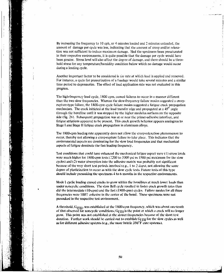
'V
By increasing the frequency to 10 cph, or 4 minutes loaded and 2 minutes unloaded, theamount of damage per cycle was less, indicating that the amount of creep and/or relaxa-tion was not sufficient to induce maximum damage. Had the specimens been presaturatedin their respective environments, it is quite possible that the damage per cycle would havebeen greater. Stress level will also affect the degree of damage, and there should be a thres-hold stress for any temperature/humidity condition below which no damage would occurduring a loading cycle.
Another important factor to be considered is the rate at which load is applied and removed.For instance, a cycle for pressurization of a fuselage would take several minutes and a similartime period to depressurize. The effect of load application rate was not evaluated in thisprogram.
The high-frequency load cycle, 1800 cpm, caused failures to occur in a manner differentthan the two slow frequencies. Whereas the slow-frequency failure niodes suggested a creep-rupture-type failure, the 1800-cpm cycle failure modes suggested a fatigue crack propagationmechanism. The crack initiated at the load transfer edge and propagated at a 450 anglethrough the bondline until it was stopped by the higher modulus surfaces on the oppositeside (fig. 26). Subsequent propagation was at or near the primer-adhesive interface, andfatigue striations appeared to be present, This crack growth behavior appears analogous toStage I and Stage 11 fatigue crack propagation in aluminum alloys.
The 1800-cpm loading rate apparently does not allow the creep-relaxaition phenomenon tooccur, thereby not allowing a creep-rupture failure to take place. This indicates that theenvihonnientli aspects aire dominating for the slow load frequencies and that mechanicalasiects of fatigue dominate tile fast loading frequency.
Test conditions that could have enhanced the mechanical fatigue aspect were I I) stress levelswere much higher for 1800-cpmn tests t2200 to 3300 psi vs 15011t psi m1ax.illu for the slowcycles) and (t2) water allbsorp•tion into the adhesive mllatrix was probably not significantbecause of the very short test prioids involved (e.g,. I ito 2 days), not allowing the sailledegree of plasticization to occur is with the slow cycle teots, Iuliture tests of this typeshould include presoaking the specimens 4 ito ti nionths in the respectve ,nvironments.
Motle I cyclic loatlhng ciaused cracks to grow within tile bondlines tit mu110ch lower loads Ihanunder lioncyclic conditions. The slow eltl ycle resillted in faster crack growth rates thandid the intermediate I 0I puiIi) and tile !ast il 800-C1cpn) cycles. Failure mllodes for ill tihreetretqulencies Were I O oliesive in the Cilnter of the bonid. Tlhews stecimlie were iiopresokedll Nthe resplcvtive test eironment.
A tlireshold. GIT, 1 was established it thie 1 8lt)-eplll frequency, which was aihout one-tenthof that observed lor iloncyclit. coliditioii,' GIITII is the pintli II Which a craick will oit) olnigergi'ow This loint was otl esablislied at tlite slower frequencies bccause tif the short test
duratiori. Further work should hie carried out t .estblish GHlII lot the slow cycles as welus for different dheive 'systtis te.g., thIlie more brittle 3501F cUre syst eus,.
4:5t

Th-is sarne effect occurs in metals such as aluminum. Mostovoy showed a comparison ofda/dN vs A G1 results for other commercial adhesives bonded to aluminum to da/dN vs A Kjresults for aluminum alloys by converting AG1 of'the adhesives to AK1 by using thlerelationship:
A K I =GjT'
where E is the elastic modulus for aluminum, psi x 106.
This comparison showed that the fatigue resistance of adhesives in a joint is comparable tothat of aluminum alloys at low values of da/dN. A similar comparison is shown in figure 48
work (ref. 4) is plotted as da/dN vs AGI and compared to the room-temiperatutre (la/dN vsAG1 results for those bonded specimens tested in this program. Also onl thle same plot aredata from Hartman, et al., Wei, et al.: and Hyatt (ref. 5), where AK1 was Converted to AG1using the relationship described above.
The establishment of GlTH for bonded joints is important because it should be possible torelate this parameter to the fracture characteristics of combined Mode I and Mode 11 loading.The existence of' this threshold point in Mode I loading suggests that if the Mode I loadwvas less than GIH then a flaw would nmever growv. T'his also sugg~ests that there should be aMode 11 threshiold or GIITH for cyclic loading. However,-as previously mentioned, mosttypical bond joints are eccentrically loaded and hiave combined Mode I and Mode 11 loads.
A The combined eff'ect of Modes I and 11 may result in thresholds that are different than theyare by thiemselves: e.g.. G11TH possibly Could be less when in the presence of Cill shear. Thisis an area that warrants further research since it could lead to sonie practical design
5.2 LONG-TERM ENVIRONMENTAL EFFECTS
L osrsgreater than 6 months tire necessary to evaluate bond durability. Both lthe stressedand corrosion aspects or durability tire timie dependenrt. Stressed durability evahuitationsrequire time for moisture diffusion and stress relaxation to occur. Corrosion is timedependent both in initiation and progression of the corrosion i-eaction. At tempts to reducetest time by using hlih stes levels and/or testing inl more au'wrssivv enlvironment ofeproduce misleading imilformat ion.
S.3 STRESSED D)URABJILITY OF CLAD AND DARE ALLOYS
I'le adherend plays a I-ole ill two basically dfifferenlt types of' durability. (These are inde-penldent of' thet adhlesive physical properties whenl charmmctcrimid fly cohlesive failures.)I Onletype is thle adhlesive failuire phenomenon thlat occurs only in lthe preselice of1 comibinled stressad Water t partlicuilarly uinder kMode I loadinitg). Tlhis pheniomlenlon is anl Intecractionl betweenl
thle adhlesive primer anld thle adhierend suirface tor wit hin t his interracial oe .which is, afunlctionl of the adhierend surf~ace: phylsical and chiemical structure and lite phlysical and0 ClIenl-
ical haraterisic tl'te adheiv-4 prinivr, Alter delanination by t his niechanisim. creviceL-Irro~sol % will occur ito varying degrees dlepending onI file ellviromnuentmal condaitionls. Thews-coad tyt%. is crevice corrosioit, which is 0ividepenen of srts
-*1mum

Crevice corrosion initiated by clad dissolution was obvious in tile salt spray tests where allthe bonds to cladding experienced bondline corrosion. Thle cut edges of all the test speci-nmeis in the program were unprotected; i.e., thle cross-section of thle composite bond wasdirectly exposed to h.~different environments, thereby accelerating the initiation otcorrosion. The pre,' ice of the salt electrolyte sets up a galvanic cell due to a difference in
EFbetween the cladding and the core alloy. These AE differences for 7075 and 2024alloys are listed in table 22. Even though the absolute values are different and may also be
A significant, it is the AE between the clad and core wvhich provides thle driving force. Oncethe cell is set Lip and corrosion proceeds into thle bondline. a complex crevice corrosionmechanism continues the corrosion reaction. Very little corrosion wvas evident onl the barealloys, occurring mostly with FPL etch (7075), less with chromic acid anodize, and virtuallynone with phosphoric acid anodize. Surface treatment also affected the degree of cladcorrosion tin the same order.
Table 22.-Comparisons of Potential DifferencesBetween Cladding and Core for 2024 and 7075
Sheet1Solution potential Potential oifference thickness,
Alloy cladding, mV Cladding/core, mV in.
I:2024-T3 -1i00. 0.0407076-T6 -920 100 0.2
The second corrosion phenomenon occurred inl Ihe bondlinecs of' both clad and bare alloy".(i~e., 7075 and 2024) inl 1400 and 160, Fleolideiisiig. humidity eniomns lotentirelyWilit EI' 123-2 adhesive inl lthe bondhine., 11w appearance of the% Crevice corrosioln was thatof t'ilil'orill Corrosion (a worml-like path. figs. 12 and 1 7) which is commiionly observed under
* Ixint films. Again. suirface treatment influotnced theý rate ol progressioni. Wvilli thle FliL.etched surfaces producing the most Corrosion and pishr-ciuioielsurfaces the leai4.
To loo0k at tile problem of' bolidhine corrosion realistically, several titivstions need to be
I I. Under What coniidtions %:all the 1(midlmle edge be adekiuately proteced. i.e., painit anldlor
-. Where fastencr holes are present through lthe buondline. how susceptible is lthe s~tructure
3. What enirnmnt ay lie envounltered tindevr What applivationl Conditionis'
This is an area whtere more work has it) tv done sio proper judgmentis cami N: tulade.
Maltny b1onds have beenl made tol cladl stifacles Will bon11dhine edgesv painited, arld Willh rivetsthroughi the Wildfinles. Only a -.1t13l twrvemnage ohf thlese tonds have dhelailiflatd ill %seviqce.
`75

5.4 INSERVICE BEHAVIOR AND STRESSED DURABILITYTEST CORRELATIONS
The most significant aspect about inservice disbonds is that almost all the failures have beena delamination of the joint at the adhesive/adherend interface. This is also true of honey-comb disbonds, but adhesive failure to the core also occurs. Very rarely is there a failureof the adhesive itself (i.e., a cohesive failure with adhesive on both adlierend surfaces) exceptas .in aftereffect when the remaining bond cannot take thle load.
This is a significant point to make, because in this program FM 123-2 exhibited the loweststressed durability of the four systems tested. FM 1 23-2 and other similar 2500 F curesystems have been used extensively inl commercial and military aircraft without significantproblems relating to the durability of thle adhesive.
With the current design philosophy and applications, these materials have worked adequately;however, Withi more emphasis onl making bonded joints more efficient (e.g., fewer fasteners,or none) and having the adhesive work at higher stress levels, the element of bond reliabilitybecomes more critical. The use of the new technology adhesives (which include EA 9628and several other vendors' materials) with improved stress/durability therefore reduces theenvironmental durability risk.
Thle inservice behavior of adhesively bonded aircraft assemblies correlated very wvell Withi theMode I loading stressed durability tests, particularly for thle commercial aircraft assemblies.Perhaps a better correlation could have been made relating to thle military aircraft structuresI had more mectal-to-mectal bonded areas been available, since most of thle structures, were ofsandwich constr~iction. 1The Mtode I durability test (wedge test specimiens and thick D('B'specimlenls) was thle Only mlethod that eff'ectively demionstrated the correlation, because thleinservicc problems are primarily adheusive/adherend surface interface oriented.
5.S OPTIMUM TEMPERATURE FOR STRESSED DURABILITY TESTS
Ani optimum teunperatutre or environmntci lor'adhesive durcability testing is difficuilt to dJeter-minle. Miuch Wovied dlepend Onl tile application and type of adhesive, Subsonic aiircraflt wouldnot gelurally vxpý.%rienlcv temperature ablove I 6W I" except around enlgines and Onl Callumflaged military airmruft. which can approach 21000 F,. A mnilitary supersonic fighter willperiodically see temperatutres greater than 2000 F. All these airtrault calil see a variety of'etivironimetital conditions jiust sitting oi lthe runway,
Eleate tmpeatuesaffect tile physical properties of' plyiSniers. and thetepraue atwihllit1 a poltymler starts losinga most o1'its strength is the glass transition temperature. 'IThel presence of water will reoduce the T'(; For instaince, Water wilt plasticite ii typical 250"1.cure ma1terial to lower tile Tl(; from aipproximautely 200& to 210, F ito approxinliately I tiLYto I 75,~F. Thelrel'ore. it' one tested this ma11terial at 1 (01" il int wet environment. its. durabilitypertoritiance would lie tow, Another v'eniaor's hirodaict Withi a slightKly igher '~l' (wet) coutld-,how slgnlicaiewlly better durablility. Tlhe selection of' I 4& F'olenihsing humiditity foir testingof 23&F elure ladhlesives ill this progrmna may. lie ntear thle Tl(; twet ) for sonic adhesives, butit 6s felt that this is a redlistic tempetrature level in termsit oft po.mible service exposure.

Higher temperature cure adhesives are typically intended for higher temperature service.The TG (wet) of a typical 350 0 F cure epoxy would be about 2500 to 300 0F, therebyimplying good durability performance below these temperatures. The question remains as towhat would be the optimum test environment for a 350'F cure adhesive-a high dry tempera-ture or a lower wet temperature. A lower wet temperature may be the most severe for long-term durability tests for two reasons, (1) water still has a plasticizing effect on the polymerand while under stress the water may still induce some creep within the polymer matrix,thereby breaking molecular bonds, and (2) the presence of water over long exposure periodswill enhance any bondline corrosion effects. Consequently, the selection of 1600F/condensinghumidity environment represents an environment that is more severe than the 140°Fenvironment, but more work should be conducted to better define optimum test environ-ment for higher temperature cure adhesives.
5.6 DOCUMENTING TEST METHODS
A ti.st method using the thin-adherend DCB specimen (wedge test specimen) has been writtenup in ASTM test method format (app. C). This test method has considerable backgroundwithin The Boeing Company and elsewhere, and the tests conducted in this program furtherconfirmed the method. It has been particularly useful in ranking surface treatment processes,for evaluating polymer interactions with the adherend surfaces, for investigating bondlinecrevice corrosion, and as a process control specimen.
No attempt was made to document the other test methods used in this program because ofthe lack of definitions of test parameters and details such as test specimen configurations,environments, and cyclic load profile.
The best test method for stressed lap-shear durability testing would include cyclic loading,with the Bell cycle being the most desirable load profile at this time, Several factors shouldbe resolved, however, before preparing a recommended test procedure. These would include:(I) the rate of loading and unloading specimens, (2) definition of the optimum test environ-ment for different generic adhesive types, and (3) definition of an optimum specimen con-figuration (i.e.. thinner adherends may be more applicable.
- The thick-adherend DCB specimen has had considerable use in characterizing adhesive frac-ture toughnes, but in a noncyclic stressed condition. Thk, is now a recommended ASTMtest mothod. reference 6. The results of cytlic test indicate that more work has to bedone to understand tihe fracture characterists of adhesives in bondlines, A variant of theDCBI specinmen used by Mostovoy (ref. 4) may be imiore useful hi ostablishing G.itj para-meters particularly for very slow cyclic trelqu•ncles.
The thick-adherenu S(CB specimen for honeycomb bond durability is also a promising test1method; however, the specilleln configuration, as well as the test conditions, needs Imiore
study.
i iJS
• " 54 1
[~~~~~~~ ~ ~~~~~~~~~~~~~~~~.... ........ ' .•. ..- ,.:"." . .•... . "" ""' .- /•-: ".'.,,i...

5.7 GENERAL DISCUSSION
5.7.1 DURABILITY OF HONEYCOMB SANDWICH CONSTRUCTION
The durability performance of honeycomb sandwich construction is a function of both theface sheet and honeycomb core. The bond durability with respect to the face sheet is thesame as in metal-to-metal bonds. The bond to the core, however, is strongly dependent onthe filleting action of the adhesive and the durability of that bond with respect to the coresurface. If no filleting occurs, then mechanical pullout of the core may occur at low stresses.In addition to the fillet geometry/core interaction, it is possible for a weak interface to existbetween tile core and fillet bond. In this case, stressed environmental durability will be low,regardless of fillet height.
Three distinct levels of core-to-fillet bond durability were observed, which were related tothe three areas of core technology. The older technology, standard core, performed poorly.The current technology cores, Dura-Core and CR IlI core, showed a marked improvement,and the phosphoric acid anodize surface treatment applied to the core added another levelof durability improvement.
Moiatuyre migration into cells was evident with both older and current technology cores. Thiswas measurable with the EA 9628 adhesive because of color changes. FM 123-2 does not
* •change color with moisture exposure; therefore, moisture ingress could not be assessed. Thecombinations of phosphoric-acid-anodized core with all three adhesives and current techno-logy cores with AF 143 did not exhibit moisture ingression into bonded cells (standard corewas not evaluated with AF 143).
Perhaps a better environmental exposure would be a ground-air-ground (GAG) cycle (e.g..the Weber chamber), which would provide a cyclic pressure differential for the pumpingaction which is probably most damaging to sandwich structure in service. This environmentwould be applicable only to sandwich structure because of the differential pressure betweenthe cell void and the outside. Metal-to-metal bonds would not respond to this pumpingaction since, diffusion is the primary driving force.
More work should be done in this area with the SCB specimen. Further refinement of' thetest method is necessary in order to obtain the maximum anmount of useful inforrmation fromtile test, e.g., introducing cyclic loading. Also, further refinement of the specinten configura-tion would be worthwhile, particularly to reduce the mass if GAG testing is to be conducted.
.S7.2 CORROSION-INHIBITING ADHESIVE PRIMERS
('orrosion-inhibiting adhesive primers (CiAlP) provide benefits from both inultlct uring and
durability standpoints. ClA11 is beneficial to durability in those cases where non.CIAP resultsin poor stressed durability of the adherend/adhesive interface. However. If applied to apoorly treated surface, It will not prevent delumninationl iMSulting from stress and water.
1' Av
Ib'.$5 *
•'-.55
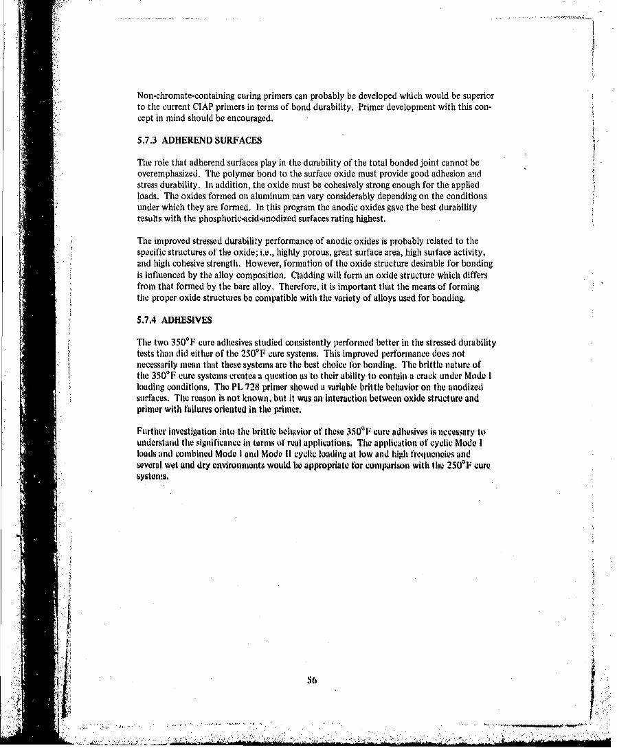
Non-chromate-containing curing primers can probably be developed which would be superiorto the current ClAP primers in terms of bond durability. Primer development with this con-cept in mind should be encouraged.
5.7.3 ADHEREND SURFACES
The role that adherend surfaces play in the durability of the total bonded joint cannot beoveremphasized. The polymer bond to the surface oxide must provide good adhesion andstress durability. In addition, the oxide must be cohesively strong enough for the appliedloads. The oxides formed on aluminum can vary considerably depending on the conditionsunder which they are formed. In this program the anodic oxides gave the best durabilityresults with the phosphoric-acid-anodized surfaces rating highest.
The improved stressed durability performance of anodic oxides is probably related to thespecific structures of the oxide; i.e., highly porous, great surface area, high surface activity,and high cohesive strength. However, formation of the oxide structure desirable for bondingis influenced by the alloy composition. Cladding will form an oxide structure which differsfrom that formed by the bare alloy. Therefore, it is important that the means of formingthe proper oxide structures be compatible with the variety of alloys used for bonding.
5.7.4 ADHESIVES
The two 350'F cure adhesives studied consistently performed better in the stressed durabilitytests than did either of the 2500F cure systems. This improved performance does notnecessarily mean that these systems are the best choice for bonding. The brittle nature ofthe 350'F cure systems creates a question as to their ability to contain a crack under Mode Iloading conditions. The PL 728 primer showed a variable brittle behavior on the anodizedsurfaces. The reason is not known, but it was an interaction between oxide structure andprimer with failures oriented in the primer.
Further investigation !nto the brittle belhvior of these 350'F cure adhesives is necessary tounderstand the significance in terms of real applications. The application of cyclic Mode Iloads and combined Mode I and Mode II cyclic loading at low and high frequencies andseveral wet and dry environments would be appropriate for comparison with the 250WF cure"systems.
* 56
•J--------
,i .*.-.*-......,

6.0 CONCLUSIONS
Specific conclusions relating to individual tasks have been presented in section 3.0 with thetest results. The following conclusions are of a more general nature and consider the overallresults of the program.
6.1 STRESSED DURABILITY TEST METHODS
I . Sound methods of evaluating stressed durability of adhesively bonded structuralmaterials were established. Two basically different test specimens are required: (1) aspecimen that includes Mode I and Mode II loading (e.g., the lap-shear specimen formetal-to-metal bonds or the SCB specimen for metal-honeycomb) and (2) a specimenthat includes only Mode I loading (e.g., the wedge test or DCB test). In addition,testing must be accomplished L ider appropriate environmental conditions, whichinclude elevated temperature and the presence of water.
2. The lap-shear specimen is capable of rating the stressed environmental durability per-formance of adhesives by comparison of the times to failure.
3. The thick-adherend DCB and wedge test specimens are capable of evaluating theinfluence oj'inter'ace variables on stressed environmental durability.
4. The thick-adherend DCB specimen is capable of establishing the critical tlu'eshold crackcontainment capabilities ot' adhesives under cyclic loads.
5. Cyclic loading of bonded joints in Mode I or combined Mode I and Mode il is moredamaging to the bond than is static loading. The slow Bell cycle (I hour stressed, 1/4"hour unstressed) was more damaging per cycle than the intermediate and fast cycles(10 cph and 1800 cpm).
6. The thick-adherend SCB specinien is capable of evaluating the relative stress durabilitlcsof the core bond in sandwich structure.
7. The older technology standard core provides poor adhesive fillet-to-core bond durabilitywith the 250'F cure adhesive. EA QW28. Newer lechnology cores (qg.. Dura-Coreand CV Ill core) tire a major step forward In providing durable core bonds, There isstill room for improved core bond durability (cg., pliosploric-acid-aluodizod surfacescoated with a bondable organic),
6.2 LONG-TERM ENVIRONMENTAL EFFECT'S
Ixpsures greater titan ( imonths� are twcessary for high-confidence durability evaluations of"bndled joints. This is becatuse talure times arc tenj? at low stress levels, and tie secondary
corrosion Interactions that ilay occur in the bondlines require long expoiure tioles for theeffects to be evidient.
S7"-
2 I ' •

6.3 STRESSED DURABILITY OF CLAD AND BARE ALLOYS
I. The presence of cladding in bondlines promotes bondline crevice corrosion in corrosiveenvironments, particularly if the edge of the bondline is unprotected.
2. The corrosion mechanism is independent of the stressed durability characteristics ofthe joint and can occur regardless of the adhesive system and adherend surface treat-ments involved. However, the adhesive system and the adherend surface treatment doaffect the initiation and rate of corrosion.
3. In general, the alloy, clad or bare, has little influence on the stressed durability perform-ance of the bonded joint when the optimum adhesive primer/adherend surface treat-ment is used. However, the alloy does control the oxide formation mechanism/surfacepreparation interaction.
6.4 INSERVICE BEHAVIOR AND STRESSED DURABILITY TEST CORRELATIONS
1. With Mode I loading (DCB specimens), a correlation was shown to exist between in-service behavior of adhesively bonded aircraft assemblies and stressed durability testingwhere assembly disbond in service correlated with poor wedge test performance.
2. Traditional test methods (e.g., lap-shear and pool) do not predict inservice durabilityperformance.
3. Sustained-stress lap-shear durability tests also do not correlate with inserviceperformance.
6.5 OPTIMUM TEMPERATURE FOR STRESSED DURABILITY TESTS
The optimuu temperature for performing stressed durability teits of all structural avrospaceWdhesives has not been defined. A realistic environment for testing of 250IF cure adhesivesystems was established as 140TF/condensing humidity. An appropriate test environmentfor 350'F cure adhesives was not clearly established and requires additional evaluation.
6,6 DOCUMENTING TEST METHODS
1. The wedge test specimen has demonstrated a discriminating capability in durabilitytesting, The test method has been written in the ASTM test method formnat andsubmitted to ASTM for ronsiderationu app. C,.
2. 'Test iethods using the thick-adherend lap-shear SCI specinitens wore not suffl" uottlyevaluated to warrant writing ASTM test procedures at this tima.
"3. The thick-adheu'end DCIH stweinen is now del4cribd as a recommended ASTIM t.stmathod, but this tes method does not include environmental testing nor cyclic loadtesting. Cyclic load testing of D00I slpilelns i not sulfilettly defined to write allmASTM toil pwocedure at this tiite.
t I 8
•I:: •:: ::

6.7 GENERAL CONCLUSIONS
1. The more brittle 350'F cure and modified epoxy adhesives consistently demonstratedsuperior environmental durability at 160VF 100% RH over the 250f F cure modifiedepoxies at 140'F/1 00% RH.
2. The new technology 2500F cure modified epoxy demonstrated improved stressed dura-bility compared to the older technology 250'F cure adhesive.
3. Of the three surface treatments evaluated, phosphoric acid anodizing showed the bestoverall performance.
4. Durability tests should be conducted to verify the stressed durability performance ofany untested adherend/adhesive/primer/surface preparation system.
5. ClAP primer (BR 127) in the bondline improved the stressed durability of wedge testspecimens compared to a non-ClAP primer (BR 123).
6. ClAP primer did not prevent crevice corrosion in the bondline.
7. There was no evidence that phosphoric acid anodized surfaces influenced the fatiguebehavior of lap shear and DCB specimens, However, there was some evidence thaichromic acid anodized surfaces did influence the fatigue behavior of both specimentypes. When tsted at 1800 cpin, some lap shear and DCB specimens with chromic acidanodized surfaces exhibited decre•ubes in fatigue performance, apparently as a result ofoxide-initiated failures.
~51
4.l..

7.0 RECOMMENDATIONS
7.1 STRESSED DURABILITY TEST METHODS
1. Continue the evaluation of the lap-shear and the SCB sandwich specimens for stresseddurability testing to the point that proposed test methods in ASTM format can beprepared.
2. Further refine the lap-shear specimen configuration, particularly the adhierend thickness.The thick adherends as described in this report may not be the optimum for fabricatingand testing large numbers of specimens. Adherends of 0.12.5 in. or less should beevaluated.
3. Adopt the slow Bell cycle, I hour stressed and 1/4 hour unstressed, as a baseline fre-quency for cyclic stress durability testing of lap-shear specimens.
4. Conduct a program to study the involvement o1' Mode I loading in bonded joints andits interaction with Mode 11 shear loads, and to identify GITfI and GlITH for severaltypes of adhesives and loading frequencies.
5. Continue cyclic stress durability tests of lap-shear and DCII specimens. assessing thleeffects of preconditioning the specimens in water prior to test arid the effect of strainrate.
6. Further refine the SCB test method for honeycomb core bond durability with emphusisplaced onl specimen configuration, testing in a cyclic humildity and cyclic pVressurecrivironmilent, and testing unide'r cyclic loading.
7.2 STRESSED DURABILITY OF CLAD AND UARL'ALLOYS
I . Further assess the effects of cladding in liondfinvs when exposed to various environ-snents to define conditions when clad could Wi used and whien clad in the bondfintishould We prohlibiled.
2. include protection of 1the cut edges using commlonl finishingp practices ad0 thet applica-tionl of new tovilnology adhiesives. Prillirs. and surfllce Prellarutionts. as Well as- anexaminautionl of lithe effect Of fastenerns tI woughi bonldlines.
~3. FV11hw1tv (fifferelt Clad alloys. as well as t1w effec oflheat trvatnienis. v~g.. 10. -T3clad vs 20244T8 1 clad.
-o"O

8.0 REFERENCES
1. J. A. Marceau and W, M. Scardino, Durability of Adhesive Bonded Joints, BoeingCompany Interim Report AFML-TR-75-3, February 1975.
2. S. Mostovoy and E. J. Ripling, Factors Controlling the Strength of Composite Struc-1 ~tures, Materials Research Laboratories Final Report, Contract No. NOOQI 9-69-C-0"3
1 March 1969 through 218 February 1970.
*3. T. B. Frazier and A. D. Lajoie, Durability of Adhesive Bonded Joints, Bell HelicopterCo. Final Report AFML-TR-74-26, March 1974.
* 4. S. Mostovoy and E. J. Ripling, "Flawv Tolerance of a Number of Commercial and Exper-imental Adhesives," Adhesion Science and Technology, Vol. 9B, pp 5 13-562, 1975.
S. M. V. H-yatt, Progirwn to Improve the Fracture Toughness and Fatigue Resistance of'Alumninum Sheet and Plate jbr A irframie Applications, Boeing Company TechnicalReport AEML-TR-73-2124, September 1973.
6. Part 22. Designation D3433-75, Standard Recommended Practice for "Fracture Strengthin Cleavage of Adheusives in Bonded Joints," A nnual Book- of ASTMV Standards, p. 908.
t.jZ
Y.

GLOSSARY
Adhesive failure: the failure mode where separation occurs at the interface between theadhesive primer and oxide (adherend surface).
Adhesive bulk properties: the mechanical and physical properties of adhesives that definetheir performance.
Adhesive/prinmer system: the combination of an adhesive and adhesive primer used in abonded joint.
Bonded system: the composite bonded joint which consists of metal alloy adherend, metal"oxide produced in the surface preparation step, adhesive primer, and adhesive.
Bondments: aluminum details joined together by adhesive bonding, e.g., test specimens,aircraft structure, etc.
Cohesive failure: the failure mode where separation occurs within the adhesive matrix(center of bond),
Posttost zone: the area of bond fracture produced after test termination by opening thespecimens fbr inspection.
is Pretest zone: the area of bond fracture produced prior to any test or environmental expos-Sure, espec-ally on double cantilever beam tI)CH) specimens and single cantilewer beam (SCB)specimens. This area is also known as the precracked area.
Rheology: th-e science treating the deformation and flow of matter.
Test zone: the area of bond fracture produced as a r•sult of environm ental exposure.
I. PAGE
A:
4i: ! ; • ; ''• ';.. ':.'.....-"÷• ;,•:,. .•
j" .I•- : - • -, . , . . . . ... . . . .., •, ,,• . • ,• ','•.y ,.p.:. .. .. -.. .. . . - - . . . .. , .. . . , , . . . . . . . . .. . . . . . .. ..-.C
I. . - - " • • •• . i. . : ' . ' , . - : . - ' .: ' - ' : " ' . . • . . . " • . . " " " " " . " • . - ' ' "

J5it ModelI: Opening mode
Mode II: Forward shear
(edge sliding)
Mode IlIt. Sidewise shear(tearing)
Figure 1.-Loading Modes Possible in Bonded Materials
Notc~h cut to facilitate clevices and to improve axial loading
j Approx.
0.26 in, 0.51 In.
7.0 In.
Figure 2.- Thick-Adharend Mach/ined Lop-Shear Speimnen
4-,~ý PAG&

Figure 3.- Thick-Adiiorend OCO Specimnws
60

Rough cut specimens,Trim then dry mill to
dimensions, shown below
(c) Typica DCB Specien oddAsml
.1olI 'oa,
1/414.0 hin.
Separatoorh~kdhted0G Se~mnShe
1iur t.(o2in. /dd
(c Tpca DBSpcie BnddAseml

F EP separator film or omitL -6in. 0.15 ~adhesive (optional)
_______ I ...t 4 .j 4-.0.125 in. nominal
0.75 in.
6 in. Z 0.125noia
2[. 1.00± Adhesive
Trim Cut five 1-in.. .2 i.Tiwide specimens
1 in.± 0.03 in. 0.125 in. nominal
1 in. -t 0.03 In. Aluminum or L 2 T .0 nstainless steel
* wedge
G n
11 n1/13 IIl0a-----

I A
(a) Streute SCB Specimen
O.5-In. cleaving face sheet 1/4, 28 bolts Insutaled on(2024-T3 bare) O.5.ln. centers
0.25 cell, 7.9 lb/cu ft 0.1 25-in. facecore, 5/8-In, cell height 404T ae
3. In
~~ Notes: 1. OpWoste end of specimen Identical2. Specimenssa cut from bonded panels 14 x >3 in.Wb Deaisai of SCB Specimen Configuration
Figure &-Thick.Adhewrend SCO Specien
Y'69

Figure 6.- Thick-A dheend Lip-Shear Modified Loading Fixture
I ~Figure 7.-Environmental Exposure C/iamlwr for 14O6F/tondensing Humidity, ShoWing Arringonwnutof OCO and Stressed Lip-S9var Spwtitnwis

BAC 5555 Cr03 anodize FPL etch
2024-T3 bare
1500 psi
Cr3 anodize FPL etch FPL etch FPL etch
20244T3 clad 707$~T6 clad 2024-T3 bare
I 6w psi~ 900IpSI
AdhuAw Sjatwie: FM 123.2/BRt 127
Figure 8.-Typical Thick-Ad1,erenel Lap-Shuar Swimon Failares for&sutaitwd-Stress Tests Exposed to 742F/Condishing Humidity
71
81.~
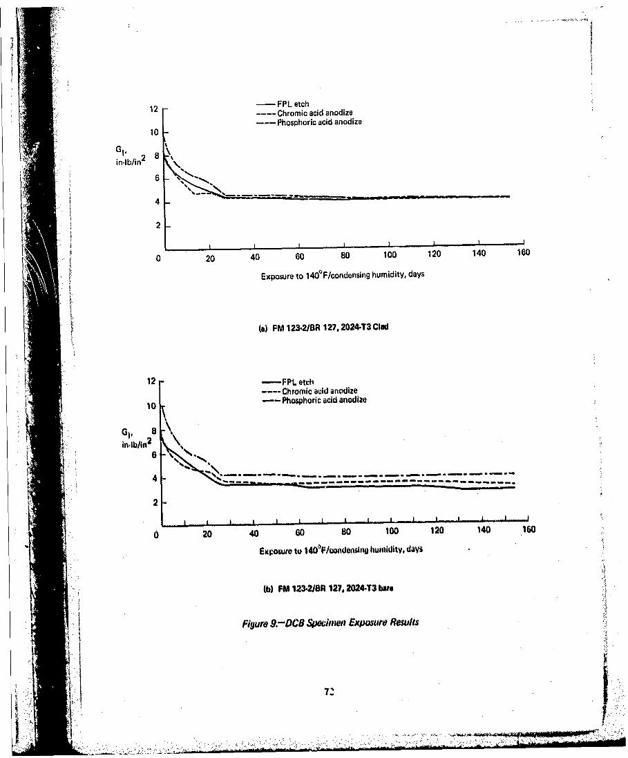
12 -FPL etch-- Chromic acid anodize--Phosphoric acid anodize
10
in~lb/in26
4-
2
0 20 40 60 80 100 120 140 160
Exposure to 1400F/condensing humidity, days
(a) FM 123-2/BR 127, 20244T3 Clad
12 -FPL etch-- Chromic acid anodize
10 -- Phosphoric acid anodize
2I I I I I I I I a
0 20 40 60 s0 t00 120 140 .160
EMxpowuo to 1 4OPF/coadonsr, humidity, davs
(b) FM 123-2/8A 127, 2024.13 bute
Figure .9.-OCG Sjjeiow expasure Results
I7

'12
12 - PPL etchChromic acid anodize
10 Phosphoric acid anodize
GI
in-lb/in2 6
4 -
2
0 20 40 60 80 100 120 140 160
Exposure to 1460F/condensing humidity, days
(a) FM 123-2iBR 127, 70754T6 dad
12 - FPL etchChromic acid anodize
¶0 --- Phosphoric acid anodize
8
inI~2 6
4
0 20 40 00 80 100 120 140 180
Exposure to 1400 F/condensing humidity, days
(d) FM 1232/BR 12?, 7076-T6 bat*
Figlur 9.-1CothweudJ
73

12 -FPL etch-Chromic acid anodize
10 -- Phosphoric acid anodize
2
0 20 40 60 80 100 120 140 160
Exposure to 140PF/condensing humidity, days
(a) EA 962818R 127, 2024-T3 clad
12 -FPL etch--- Chromic acid anodize
10 --- Ptiosphoric acid anodize
8
0 20 40 80 80 100 120 140 IGO
F.o~r to 14041m/cwu~uitg humidity, dlays
W~ FEA 9623/BA 127. 2024-T3 bare
Figure 9.-(Continued)
47
t.- ' . 7

12 -- FPL etch---Chromic acid anodize
10 --- Phosphoric acid anodize
8
in-lb/in2 6 k
~.--4-- ------- -- -- -- -------
2
0 20 40 60 80 100 120 140 160
Exposure to 14OVF/condensing humidity, days
(9) EA 96281BR 127. 70'15-T6 clad
12 -P PL etchChromic acid anodize
10 - Phosphoric acid anodize
AG
26
2
o 20 40 GO 80 1100 120 140 1600
Expowvo to 114OPF/cwn~minJg humidity. days
(h) EIA 928BA 1 27, 70164T$ bato
Figutro 9 -(ConfilluJd)
75
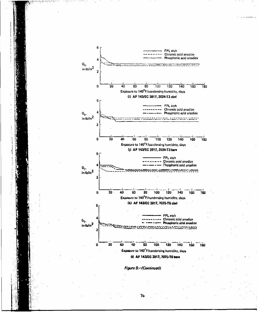
6P ecChromic acid anodize
4 Phosphoric acid anodize
in-lb/in2
2
0 20 40 60 80 100 120 140 160 180Exposure to 1400F/condensing humidity. days
(i) AF 143/EC 3917. 20244T3 clad
FPL etch
I ----- -- Chromic acid anodizeG1.
41- - - Phosphoric acid anodizein-lb/in2
2 -
0 20 40 60 80 100 120 140 160 180Exposure to 1140OF/co~idensing humidity, days
Wi AF 143JEC 3917. 2024-T3 boro6
FPL etch- Chromic acid anodize
4 M__-----rosphoric acid anodlie
2-
~~ ~ -I-- A - -~
0 20 40 00 80 100 120 140 100 180Exposure to 1140PF/rondonsttvlu humiduity, days
0 ~(k) AF IO3UE 3917, 7076.T6 clad
-----------------------------FPL oicltG1, ------- Cbrornic acid a'iodize
2 Pluwoltwicatrid anodize
0 20 40 W0 80 100 120 140 IGO I180
-Expoguret 4 4 /odnin uiiy ly
011 AF 14.1EC 3917, 70164T6 bIsm
Figrd 9.-?tniuoi
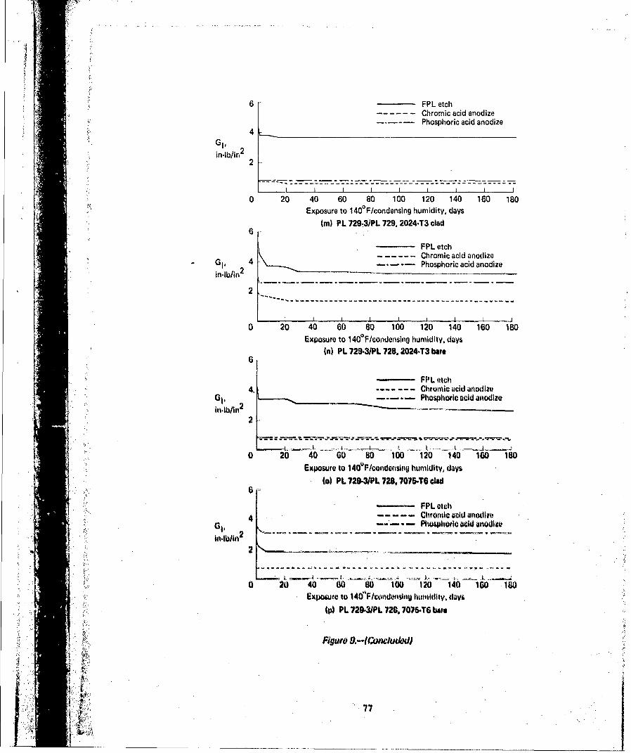
6 FPL etch- Chromic acid anodize
-. - -~Phosphoric acid anodize4
G1,in-lb/in2
2
0 20 40 60 80 100 120 140 160 180Exposure to 1400F/condensing humidity, days
(in PL 729-3 /PL 729, 2024-T3 clad
FPL etch---------------------------------Chromic acid anodize
G. 4 Phosphoric acid anodizein'Ib/in
2
2
- - -- - - - - - - - - - - - - - - - - - - - - -
0 20 40 60 80 100 120 140 160 180Exposure to 140P F /condensing humidity, days
(n) PL 729-3/PL 728, 2024-T3 bar*
4,--Chromic acid anodize- - -Phosphoric acid anodize
in-lblin2
2
1.0 20 40 60 80 100 120 140 100 '180Exposure to 140PF/condensing humidity, days
(a) PL 729.-3/Pt 728, 707646O clad
-FPL etch
4 Clwtwnic acid anodla'
2
0 20 40 60 80 100 120 140 IG0 160
6M1)owet to 11401Pcondw~nyln humitildy. davs(p) PL 729.3Pt 728. 707164 but.
24K
77

7075-T6 bare
f,70754T6 clad~hshrcai
2024-T3 bareandz
20244T3 clad
70754T6 bar]
~ 075-T6 clad
______Chromic acidanodize
2024-T3 bare
____2024-T3 clad
707btt 6 Wae
70754TO ctad
202443bar. PL utdi
~~ 2024-T3 cWa
Is) With 20 W..ke Expowtu toW10F/Coadounaen Hutmiay
FyRqti IO.-Opwxtd OCO Ujdtiuvwvs &uuMid k~viJ AL 729L3h'I 72B
AL

7075-T6 bare
7075-T6 clad
Phosphoric acidanodize
0204-T3 bare
2024-T3 clad
707 5-T6 bare
7075-.T6 cladChromic acidanodize
2024-T3 bare
j ~ j ~ T h y2024.T3 clad
5' ~707&.T6 bW
70 '.&T cladFPL etch
"~2024-T3 bus
tiw~ak growth t
(b) Witil 7? W44Ws Expowe to e 0/odad u
Figuto Ya-l~unciudedd
J ~79

-~ . ~7075-T6 bare
7075,T6 clad
Phosphoric acid01 anodize2024-T3 bare
7,.. 2024-T3 clad
7076-TG bare
7076-T6 clad
Chromic acddanodize
*1 2024,T3 bare
4 ~2024-T3 cwlo
707646 twoe
707V6B clo
2024-T3 bare
20443 c4:d
(dl With 20 Woks' E~p~ux to 14OVIF/Condonsng Humld~ty
4. Fugwe 17.-Gpimei CO j4irawvis Btmded With AP 1431EC 3917 *ytwni

77-6bare
7075-T6 clad
Phosphoric acidanodize
2024-73 bare
2024-T3 clad
U F i~' '~ ~7075-T6 bare
Chromic ai
anodize
2024-T3 bare
A 2024-T3 clad
70764T6 Iwo
7075.T6 clad
FPL etdi
2024.T3 bate
AM 2024-T3 cwa
*--o CtaCk of owit
b)With 77 Wkeek 'C'xpae to 14OePjCandential Nnk udtv
Figure I I.-tConcludedIO
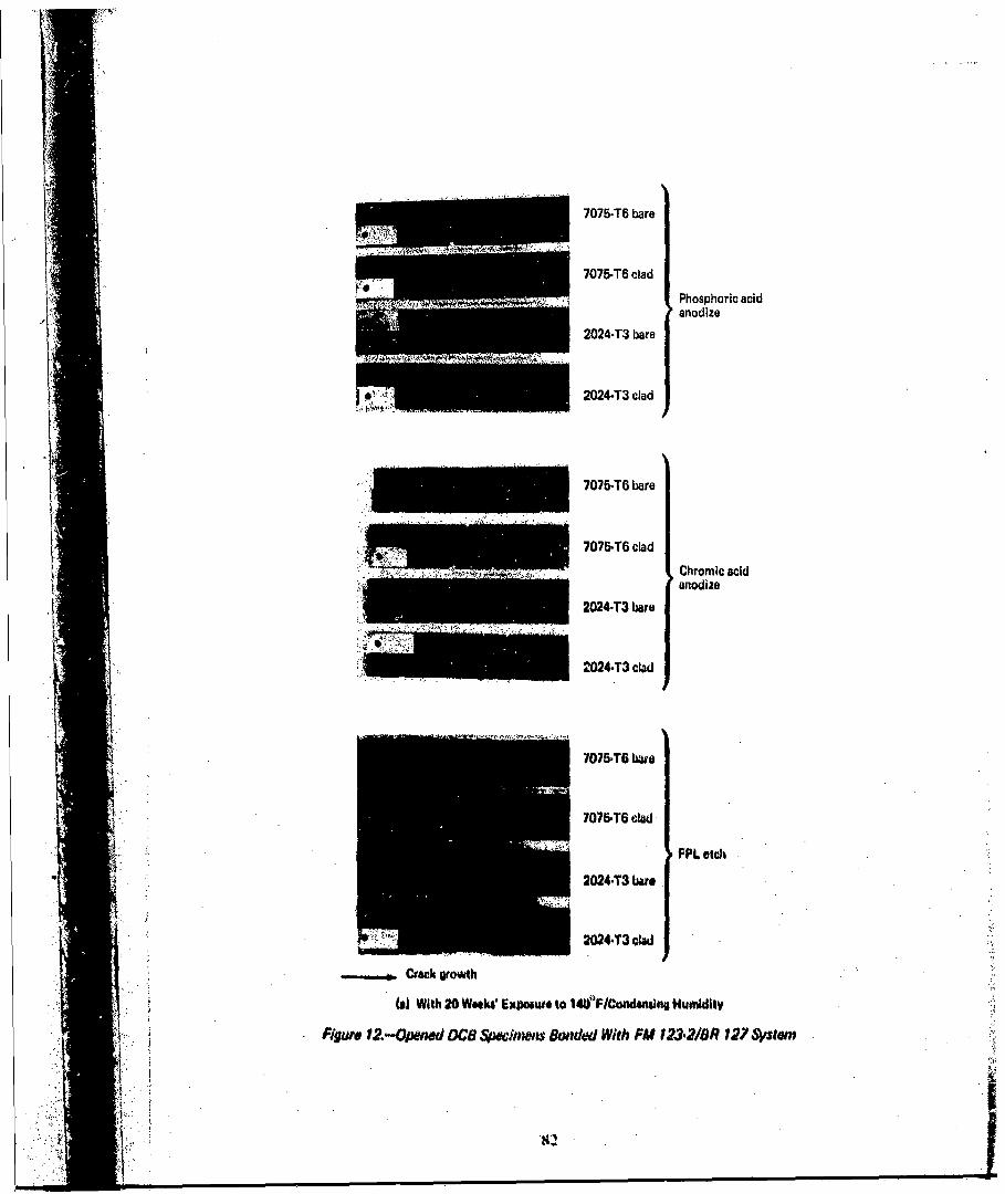
7075-T6 bare
7076-T6 clad
. . . .. . . . . ....... Phosphoric acidanodize
2024-T3 bare
2024-T3 clad
- ~707&-T6 clad.......... Chromic acid
anodize
2024-T3 bare
2024-T3 clad
4ý707r6-TO clad
PPL sobc
2024.T3 bare
=044T3 clad
SCrack growth
to) With 20 Week. Expoure to WF~ICandmn.ng Humidity
-Figute 12.-Opened DC8 4w-oewinms &bidod With FM 123-21OR 127 Systen
I8

7075-T6 bare
.... ....... I7075-T6 clad Phosphoric acid
*: ~ Ianodizeexposure
2024-T3 bare
2024-T3 clad
................................ ...........
7075-T6 bare
. . .. . . . . .. .
7075-T6 clad Chromic acidanodize
.......... .... 77 w eeks'exposure_________________________________ 20244T3 bare
2024-T3 clad
7075-T6 bare
70764TO clad
86 weeks'
SCrack gowwh
(b) WMt up to 86 W..ks' Exposut. to 141f F/CondsmsIng Hum~idv
Xguro 12.-ICoiw 4do0

J 7075-T6 bare
n7 7075-T6 cladPhosphoric acidanodize
2024-T3 bare
2024.T3 clad
.............. 70754T6 bare
7076-T6 cladChromic acidanodize
2024,T3 bare
2024-T3 clad
I 7075-.TO cladFPL etch
2024-T3 clave
O"CAct growth
Wa With 20 Wtaka Estocaut to 14OQPFICwornvain Hw~dtv
F~yig" 13.-Opend DOB Sjlionwies Bonded VWi EA 9628/BR 127 System
84

7075-T6 bare
te ~ 7075-T6 cladPhosphoric acidanodize
IM 86 weeks'- .,.~..j2024-T3 bare exposure
2024-T3 clad
7075-T6 bare
7: ~" 70756 clad
Chromic acidanodize77 weeks'
20244 bare ex posure
2024-T3 bare
I2024-T3 clad
eaasm
I K.'

12 - 1200 F/ condensing humidity-1400 F/ condensing humidity
10 -- 1600 F/ condensing humidity
in-lb/in24 - - - -- -n -- - - -- -- ---- --
2
0 20 40 60 80 100 120 140 160
Exposure to environment. days
(al Exposure Results: FM 123-2JBR 127, 2024-T3 Ova, Phosphoric Acid Anodize
12 - 1200 F/ condensing humidity--- 1400 F/ con~densinig humidity
161f F/ condensino humidity
10
ln4W~%4 - .%- n ni b b
in., 2-
0 20 40 600 80 100 120 140 160
Expowto to anvironnient, days
(b)l~oaweResgits BA O829$BS12P.2024.13 Bas. Phoaphouloclii Anodiz
Figure 14. -binftue olO Test Tenipiwur wn 0C8 Specimen
---- --- -- ----
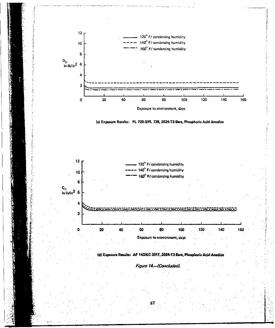
12 ____10 /odnighmdt
10 1400 F/ condensing humidity
1600 F/ condensing humidity8
in-lb/in2 6
4
2
0 20 40 60 80 100 120 140 160
Exposure to environment, days
(c) Exposure Results. PL 7294MP 728, 2024-T3 Bare. Phosphoric Acid Anodize
12- 12 F/odnigh idt
- --120 F/ condensing humidity
160P F/ condansing humidity
in.wwi
* -nf n- S a -.- ---- - - - - ---- -- -------
2
0-20 40 60 8.0 100 .120 140 160
Exposuio to @.ionwonwnt, W, VA
id) Upwo aueAhts: AF 143/EC 3917.2424413 Ova, PhoaWo~ Ae)dAod
Figure *.-(Coaclaclod

C4)
I Iwo
000
as4

00
II"
&4
, N
IVU
tov
U. •C .0 o•
J.J~
SIN•..
I * (.~ -
••" i.;

o 0
0 0
N0
0
o
0•
0)
m
o N0(U
m C
~ t)o
a
t t3
~C'4
0
I i I ' •a9
0 0 t
.
a

LL
CN
a
Cdl
(N IN

a- IY
C.) , I.t
(N N (N .
(N N (N LO .
I. I-(N -~ ~ E
C~JCN NCN A Co
I EINr
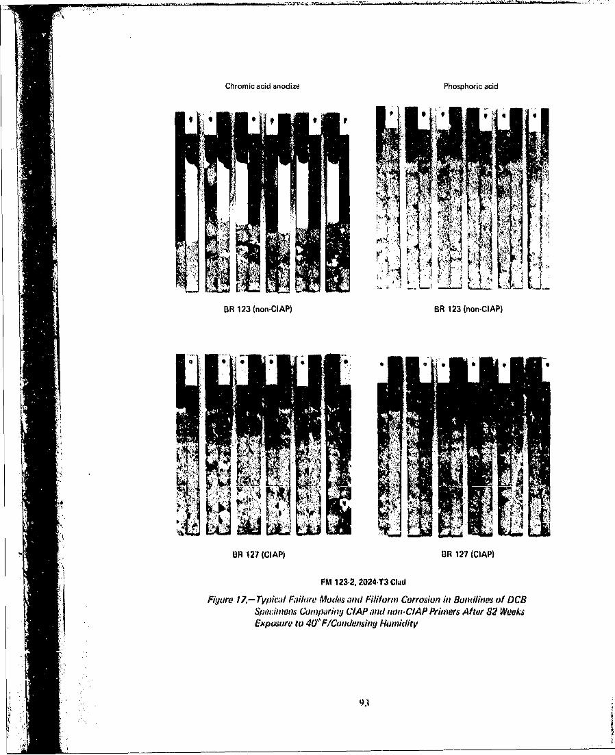
Chromic acid anodize Phosphoric acid
WI
J~ OR 27(CIP)OR127(CAi
FM~B 123.2 202onT3lAP)
BRn 123g (nonn-ClAP) riiysAtd 8 W~
pt wi ; C' y
Extuvto4"lonosn Hmdt

6
>50%%adhCC
10-20% adh CF
I ~ ~50% adh CF ~%dC
Face sheet: 2024-T3 bare
0 PA* Core 4 PA face sheet 'Phosph~oric acidSPA Core + CA* face sheet anodize
2CI Duri-Core + PA face sheet "Chromnic acidSDura-Core + CA faco shoot anodize
'~CR I II Core + PA f ace sheetj V Standard Coro + PA face sheot
0 020 3040 60 6Exposure to 1140'~condonsingj humidity, weeks
(a) SCO Spadnmets, EA 9628/6111127FgRpm 18.-Inflienct, of Honeycombi C'oro and Fact ~Shout &,rfacvi Trw- tmenats
un Envirollo,,tal Durability
vi
44A

5 5% adhesive failure (core-to-fillet, OF)
450%adh CF
5% adh CF 50% adh CF
Face Sheet: 2024.T3 bare
3
OPAcore+PAfacesheet� PA core + CA face sheet
0 Dura-Core + PA face sheet
A Duro.Core + CA face sheetc�2
I I I I0 10 20 30 40 50 60
Exposure to 140�F/condensing humidity, weeks
(b� SCO Sjodmans. FM 123.2/BR 127
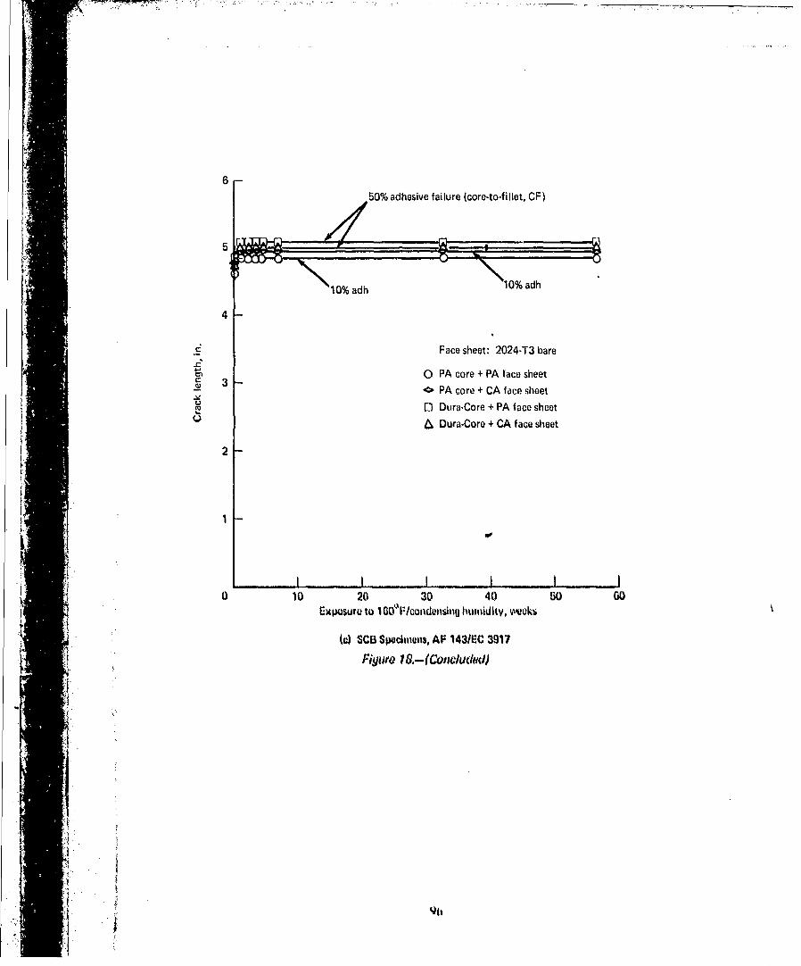
650% adhesive failure (core-to-fillet, CF)
10%adh 10adh
4
cý Face sheet: 2024-T3 bare2c
0 PA core + PA face sheet.( 3 < PA core + CA face sheet
2 n Dura-Core + CA face sheet
flDura-Core + PA face sheet
tV
10 10 20 30 40 50 GO
Exposure to I G&F/conduiisinjj humi~dity, weeks
(c) SCL3 Specimens, AF 143/EC 3917fiyuro 1 &-l(Conc/uc4<c)
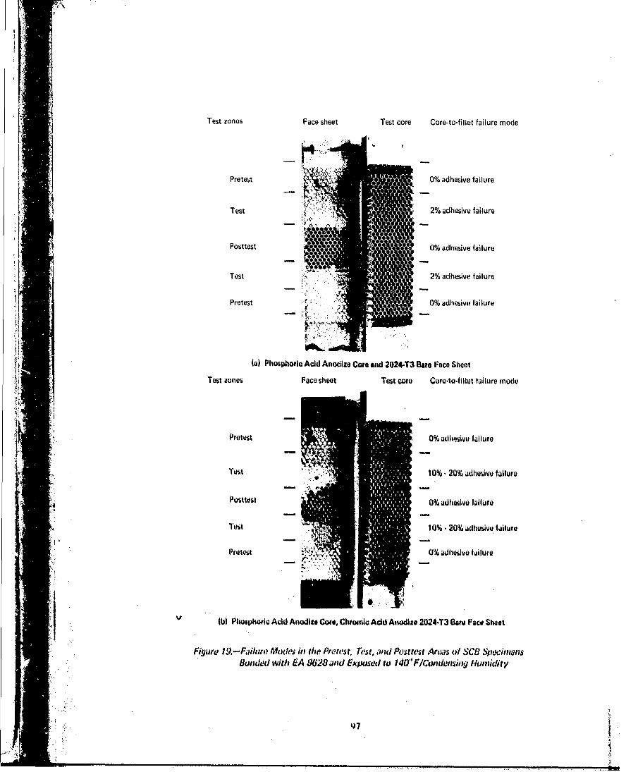
Test zones Face sheet Test core Core-to-fillet failure mode
Pretet 0%adhesve filur
I PrTest 0% adhesive failure
Postes 0% adhesive failure
oTtest 2 % adhesive failure
Pretest0% adhesive failure
(a) Phosphoric Acid Anodize Core and 2024-T3 Bare Face Sheet
Test zones Face sheet Test core Coro-to'fillet fai lure mnodu
Protest 0% adh'lsiVe failure
Test 10% - 209% adlhesivo f allure
Pumost0% adh~esive failure
Tust 10% - 20% adhesive failure
Pret~t0% adhesive f olluto
* (M Piwiphtorie Acid Anodise Core, Chromic Acid Anodize 2024-T3 Gore Face Sheet
Figu~te 19.-Failure Mode's in the~ Pnt'st, 7'rest, wid Posttest Artss oft $C8. pdiw&.indo'd withu EA 9628 ~wd Expuuod to 140"F/~'ondwusinjj Humidity
47I_0I

Test zones Face sheet Test core Core-to-f illet failure piode
Test 00% dhesive failure
Prettest 6~0% adhsvalr
Test 100% adhesive failure
Prostest ~ 4 0% adhesive failure
Prewsig0re19.sivo failur
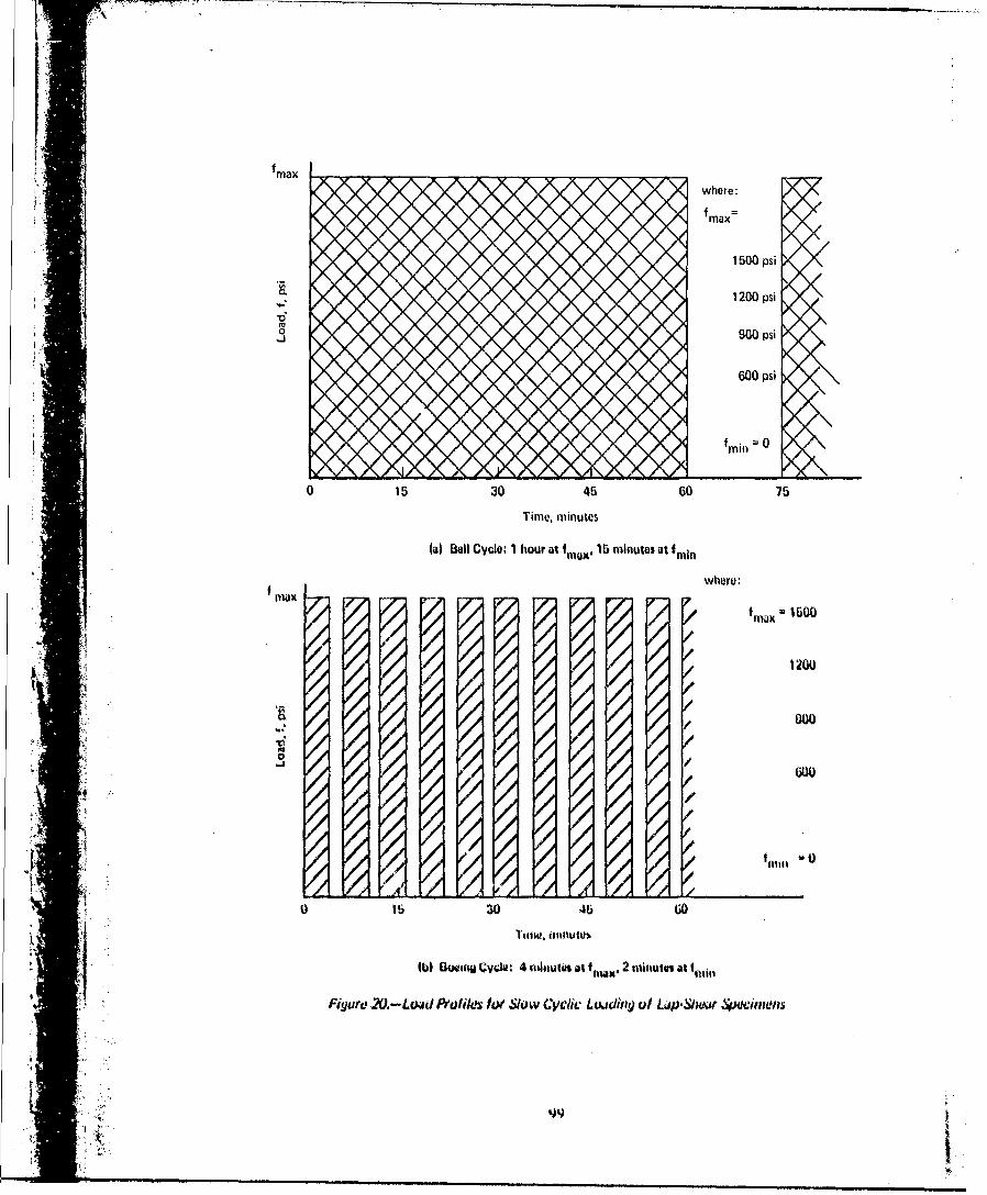
Uf~max
where: \/f N/\
max
1500 psi
aL 1200 psi
*0J 900 psi
600 psi
tmitC 0
0 15 30 45 60 75
Time, minutes
(a) sell Cyclo, I hour at ia,15 minutes atfmi
whore.
/0150
/,0 1200
00 X.,
aZ /
/,/
0 lb 30 46 60
(bi) Boeingj CVcWu 4 tnlnutas at $~X 2 trotiiws as t~
Figure 2O.-Lwd Au fils lot Slow Cyclic Lcuding of Lap'Shikr 4wcitnaws
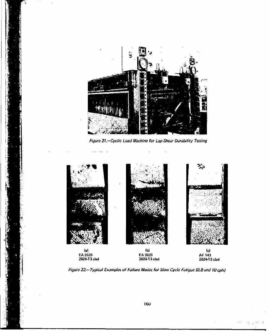
Figure 21. Cyc/sc Load Machine for Lap-Shear Durability Testing
l"A
EA 9628 E A 9628 AF 143202443 d 2024-T3 dad 20244T3 d"d
Figure 22.- 7y*picEam wples of Failure Mocks for Slow Cycle FAtiyue (0.8 and to cph)
ItU&

.0 -'N
u 0 0
co(N Lci - u
LL 00 c 0CD 0. N
L,
'30
to cro319
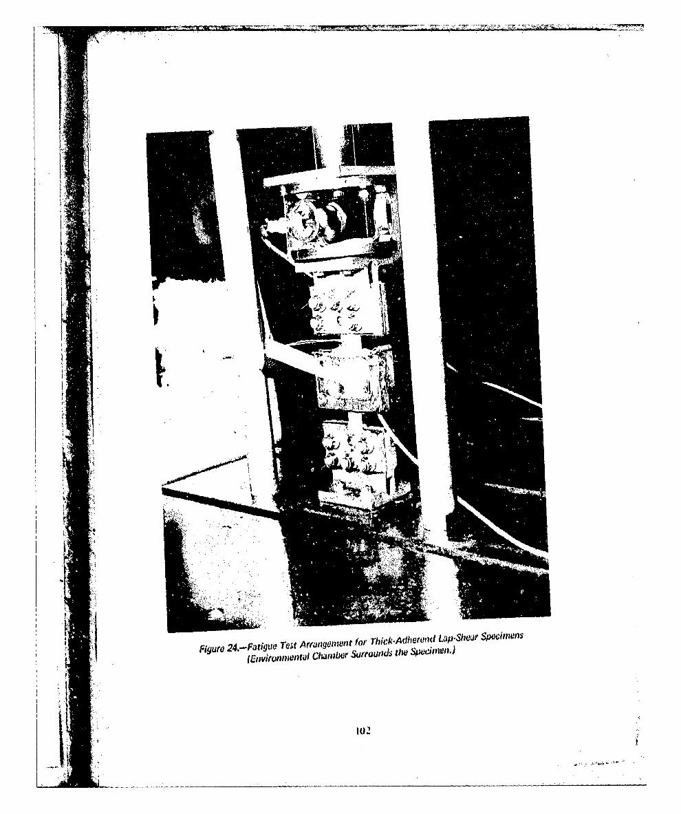
Fiue24.-FatigueTetArnaItfsTi&AietIiLpS'J WnII
(Envkullflo luta lchjlbr surtoods Ow .p~nII.

0000
UMN
00 L0
0 CoL(o r U.(1
(0 Lo ýo I];
1+1 -a 0
L4.4
Z~~LL '4
ink
t0o
'1001V
-zu.

Fm)
00
C.) (0.0 Z__ _ _ _
- 00, < . - -o
WVU It 0- --
co~ 0
Lo;, o
- U.
I~~ Oil -

E
OCDJ N0
cc 00
CL 0 0
C)--- (D L
(00 (CN r
It o 0 00
cr~cZc
~ NC0
ar V.E
4S
8" 0 ,
LL0
(~, to

00
cr 00
C-4L 1.0 L)a0 - Cn -C, ( C l LOC6 <! LO
+- o.c 00
.U.I
Ln

I))
0000
coo ~' cco E
0 O C) -0~~)C 0
0 (DLL 5 N-
*C X
+: s
it 0
('(J
IMI 4..IW
$ 4O

K DirctionMachined notch
of fracture 4Aluminum~- -~Aluminum oxide
Adhesive primer- Adhesive
Failure at/nearprimer-adhesiveinterface
(a) Side View of "Typical" Failure
L Failure of primer.oxide interfaceor In oxide
(b) Side View of "Adhesive" Failure
j..-Test overlap area 0To speolimen end
Areai ofDiretionfast
Di rectire crack IFingrniail shapedgrowthareas of slow
,J crack growth
(c) Top View of Fracturt~ Surfaices
Figure 26.-Fallow Mode Charac~teristics of 17 ick A yetnid La 1is1 r 4wiiwili~sTested at I8W0 opmn, R 0.06.
A J

-~Big! -i-
4T N
.....
I..L
PhspoicaidCro i aianodiz anodiz
43ur 2Z- Tyia 4-ha aiue t1Wei 04 3WoBne
WihE 621R11
t1k9

450X
90X
Figure 28.- Topugraphicil Fiiresiu Which Apptr 'to Be Fatigue Striationsat Adhosiv.e*Primar /Itoterli Zone

H
K 1
4
A -
AI>1
Figur6 29�-Fas� C�c�ic Load Machine for D�B Speci,?wns
II�
I ti*
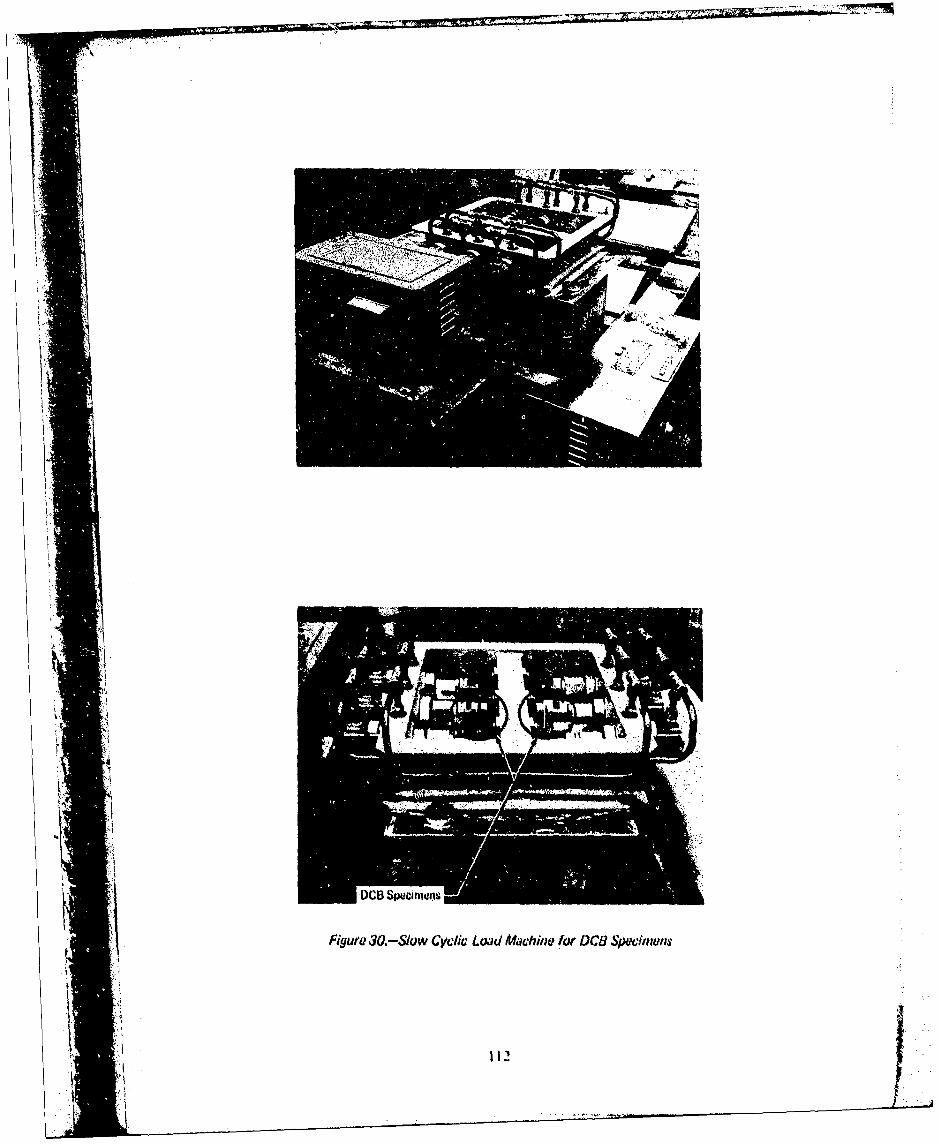
Figur 30.-Slow Cyclic Lowd Machine for oCa Spwitans
1 112

10-1 --
A 0.8 cph (Bell)0 10cpm0 1800 cpm
Surface treatments10-2 Phosphoric acid anodize
S- - Chromic acid anodize
10 _3 -
S10.4
11 -
11/
t,•a ck junipwllOut GITH
10-7 f~~ •• •/ Not
10"1
A 0.8 cph (Bell)0 10 cpnmo 1800 cpm
Surface treatments2 Phosphoric acid anodize
102 -- Chromic acid anodize
10/0
10"4
KV
10"5
ki Now
ii.
" I • %• I U Wit ! d i nl G IT 4 l o t
{] ,1 I o , 1 / fi
• I~~~b ) S p s wnse n l e i t od at R o w " T ei l w oll u l , .W al, E A S U W ON0 t 1 2 7 , 2 0 2 4 4T 3 B uisi
figure 3A,-(Continued)
114I
S; ,,b.
i~I 'I I
;t, 11 /
•~~~~ //! 1111

10- 1
A 0.8 cph (Bell)O l0 cpmAo 1800 cpm /
Surface treatments/
10-2 - Phosphoric acid anodize 0Chromic acid anodize//
10- 3
10-7/
'0 2AO alI1,1111
spdwi ese 10FoOV 2% N. AOWO 17204T/Bt/iur 1.-Cniu

10-A 0.8 cph (Bell)0 10 cpm0O1800cpm
Surface treatments
Phosphoric acid anodize-- Chromic acid anodize/
1104/
10-4
A7'N11' /CI OA110' Oi/01
U3
L
11

A 0.8 cph (Bell)0 10 cpm0 1800 cpm
Surface treatments
10-2 7 Phosphoric acid anodize
-- Chromic acid anodize
10//
104
%ki it GIT14 for
11 0 10 20
Y to) Specimoi., Tested at 141VF. Wet. EA 9628/BR 127, 2024-T3 D~an
Figure 31-l(Conciuddid)
117

N~~' (a) 140OF Wet
&E 7075-T6 Bare
Phosphoric acid~ 180 cprnanodize
(b) 750F Wet
-. Crack growth
____________________________(c) 1 40F Wet~ . 0.8Bcph
7075-T6 Bare
- (d) 75 F Dry Chromic acid1800 cpm anodize
Apparent oxide failure 22.3Br
(e) 140PF Wet____ ___ ____ ___ ___ ____ ___ ___ ____ ___ ___ 1800 cpm
2024-T3 Bare
Adhesive failure
(f~ 140')F Wet_______ _______ lcprn
2024-T3 Bure
FPL etch
1 2 ! 2024-T3 Baru
Figure 32.-Frawfture Appoarines From Gvdie~ Loading of DCB SpweimeiisEA 93628/OR 12.? Adhosive Priwer System,.

STAINM Mi'F C111UAL SISTIM LEW IICONAMO 25e1 IMUK AN-SYSICS1
fowI2U-aji-MI-CI? If 121-2/Ul-127 IA til (1016291111IZCIAP
NZ4.UCIA ff4U 461CA 2624-T)44M 344-13 clA MI4419M Ws4? ctll Tt-T4L 114amil
-;33 £141
STANK" 2544 cuI ll. ~SYSTEN NINO ISCINOCI HeF CMO AWA.SIIII
IN 123-2 /1"23 MilM-CIAP To 123-1/Ul-l2U tiA? [ANNIIR111CIA?
104,1-I1441 16404- U114 2414-)1141t 241014-141,1 14.4Ts LU W4.-143 UK 1411-14119ti 141114434
Anu 11 u NssikOlI7o slcmA iiINW-'u-n O-CI? IN11Hwil 44P WNINw~lCIA
Ts,
(a)30-ay xpouAFigue 33-Wede Tit Spchnos Epsd o5 il Sa
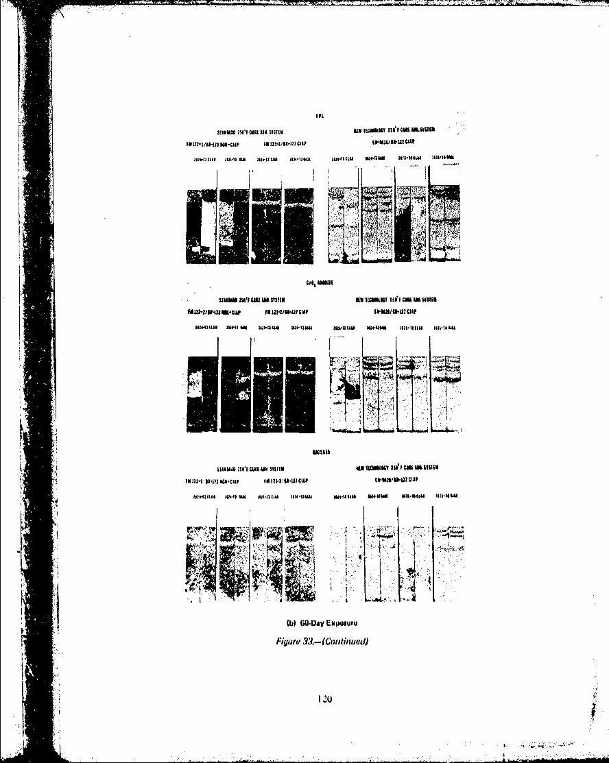
F~L
STIKDU 2501 CIIR A411. SYSTEM NEW T(OUhILOV 25IfI cum mm.ulm
FM 123-2/II1Z13 ECU-ClAF FM 123-2/91-121 CIA? A IUWCP
1124-19t~lS 2424-13 UN 1114- lUAI 1414THU21 IuZ,4ituI mt-uI.u lo1511u liil-to UK
Co,0 ANNUL
11TWOIN3 C1111 AR SYSTEM VANUISC ASSFv GIse UK mus1Lm
uaOW-vsw lm-up, 1M 121-2/111-111 ClA? lkM2*,tua-CIA?
W441&C Ul4II N 12111W 114JM u"-AW IU-1443,11 211ll-411 lll-I.IAUh
td-4I
93 13 2 11.9 3 M I SCl O cu m Y TM I"l- l CIAv ( I li I an Am so
l*1231 .1j ?3uI# I NLF INIII 1 413-.11- I 1111 clip hUN IIMC1AF h
W GO-Day ExpOSur
Figuro 33 -(Continued)
120

L .smuasI 201 CUI AN. SvSTI EN TM1"w 26el urM MUSm1INM IUS -2/11flmu-CIu F11123-2ihNWHCIAP (will/w~llCIA?
241443noag m14q$ Ow lf4TSCLU 124l-TIIU Mu4.13C c oue 12- K 136 -i tou .a iui~t*Si
1141
CV03 £53111STAAKU~250 150 C13.5YSTM5111OOG
IM TqUIR IWI~I U5A311111* famo lwI MAU?
iaa
(c) OO.ay Exposure
Figure 33..-(Cwitinuod)
IW

I"I,
SrAN&MO 2541'1 Cill AM. SYSTIMN INEW TRIMIWY 251! FU CM J. SYTIM
Of tiztu13f ION-CIA (IN 12)-2/U-121 CtA? &~8.~CA
M441UJAL** M40213$ MU 302-13 CUD 2034-T14" 30443J (CUD 34,-IIAU tois-fCi1i 7fIAII-t
x~
kI -
1 S"I NM AC b$wA uN.iII ".1W " W41UUA lon-I' IM &Hi.% -Itu
(d) 180Dasy Exomuro

STAN"M 20 to Ass SYTM VA11 Tmuiimy iM'iCNAN .swwi
R1 23-2/61.U1CIAP
Ill$OI 4.3 a 61-1 CU 41-1un 144-1 U U4.s 43 Ncu 111T I
.. *,w..*
C(e ) 3 4aNSExpsr
s~~~l ~ Fgur 33.cus M SIYRMMl u uod) s21 C niI
11U-?U13 n-up IN122/1II RA ~ ~ /5~;23A

6+ in.
WWedge
Bondlines ~ Tripler = 0.080 in. 015n*11 ondine Doubler = 0.040 in.0.125 in. ()Skin =0.063 in.(b
Wedge Test
7 in.
0.5 In. 0.040 in.1 0.003 in.Machined Lap Shear
A A (b)
I0.063 n'A ~A-A(u
Powta Shsv
:1. Note.(a) SkIn.doublor hond (SD)
*(b) Uoublor-triplar bond (UT)
Figure 34.-Specimen Configuration for Commercial Aircraft A
1* 124
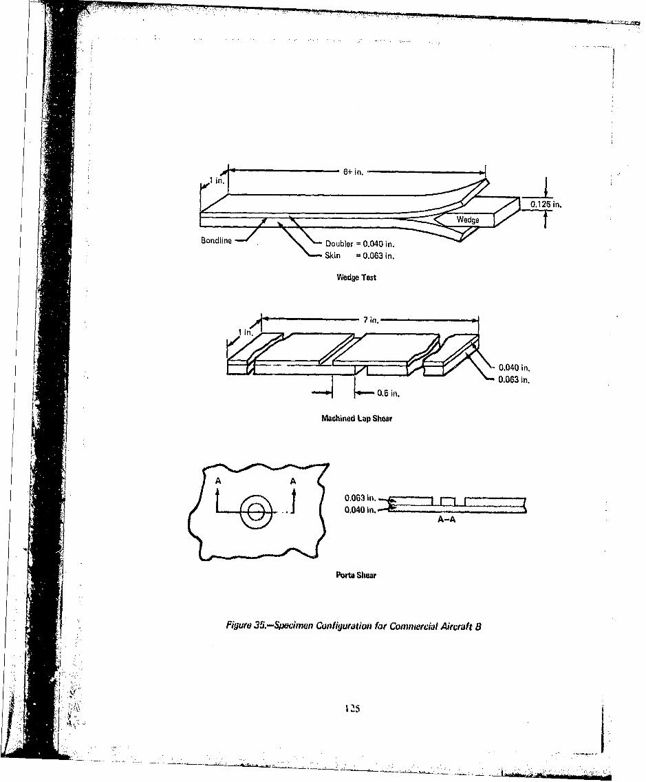
____ ___ ____ ___ ____ ___ 6+ in.
0. 125 in.
Skin = 0.063 in.
Wedge Test
j 0.063 in.
Machined Lap Shear
PwUt Shcv
Figur 35.-SPOe&f,,w1 Con figuration for Comnnwrcia/ Aircraft 8
1211

0.36-in. _doubler0.036-in.skin
hot-bonded to aircraft skinand doubler
Wedge Test
0.036-in. skin j0,036-in. stiffening doubler
CI~rnblngD tubi Pee to aircraft skin
A-A
J ~ ~Figure 36.-Specianon Con1figuration for Coinnwnial Aircrat C
112o

Stiffenera Opened here toDoubler weg-btCedSkin .Stiffenerar
0,045 in.--
Detail 1D: Specimens 1 and 2
[Stiffenera / .1i Opened here to_______________0.05Q_____in.__ 0. 125 in. with wedge-
Ski2nin
0.045 in.-.
Detail 20: Specimen 3a
Triplor nOb and$Doubter U.03 ,
W~all2D., Spciamu i3b and U
Note:
All ocihunws I int. wide and 0 In. tongaStiffaning doubters IwNwtiodad to alruatt details
Figare3 - e Cwfi~u'ation lot Cornuwrcal Aircalt D
127JI

AF 126/EC 2320, 2024-T3 clad
f = 300 psi
Environment: 140PF/condensing humidity
100
U, (VU ~801
400
ij 20
C3~4 CD3~ 4 ~ w la
2
2 11

C'13
C14 - N 00N
0~i c h-
'4.
-0 c-Mi M cu
LL 0
0 )
(N0 C 0 0
U, N
'0 -L
~N(N 4 o
0j
wn Vuf Itiativil43crZ

CL~ ..
*W 0
A /00_ _
aa8
"MO
10
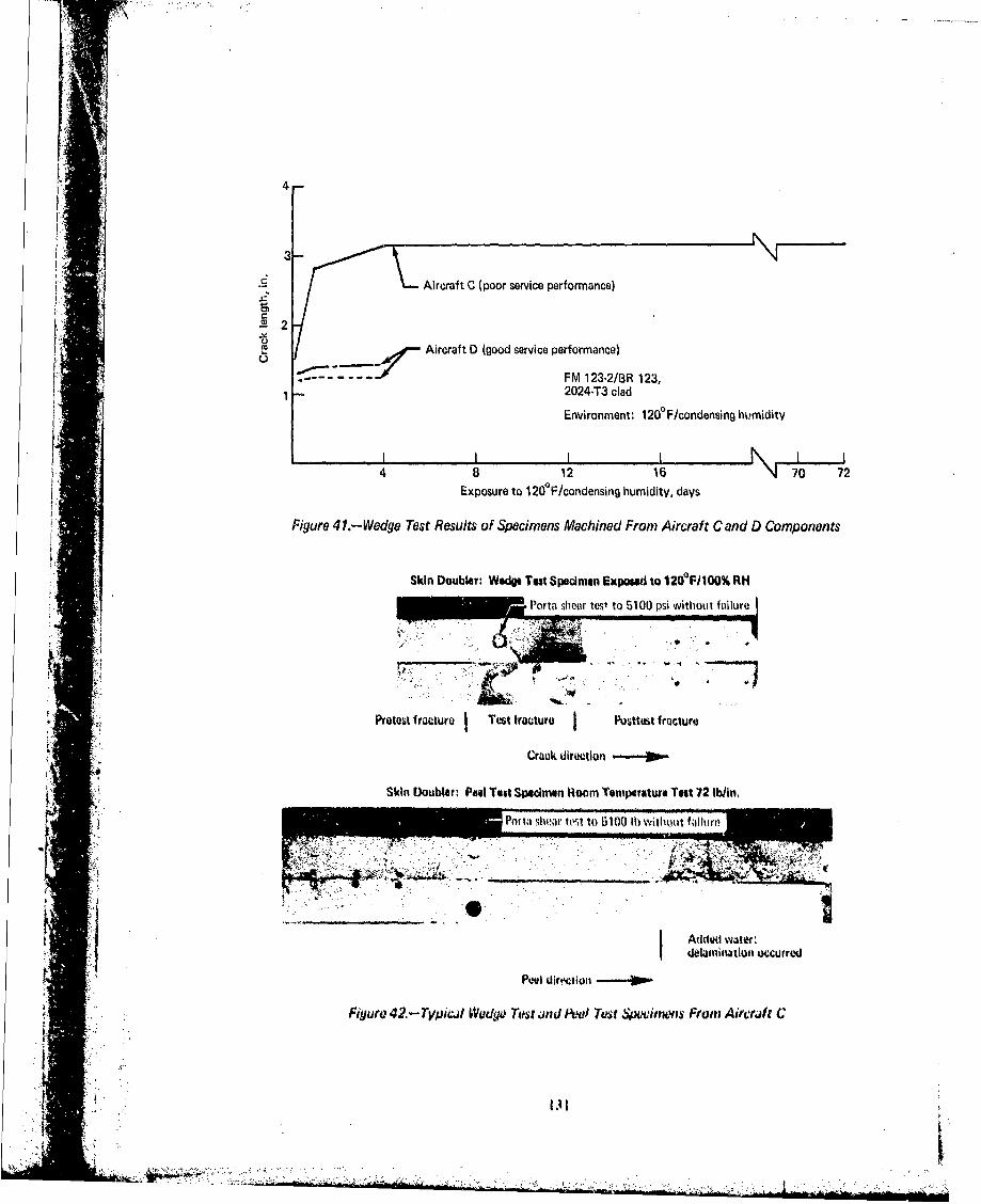
1;----4-
Aircraft C (poor service performance)
Aircraft D (good service performance)
FM 123-2/BR 123,1 2024-T3 clad
Environment: 120PF/condonsing hukmidity
Exposure to 1200F/condensing humidity, days
Figure 41I.-Wedge Test Resuits of Specimens Machined From Aircraft C and D Components
Skin Doubler: Wedg Test Specimen Expowat to 1200 F/100% RH
Protest 1rwature Test fraicture j Posttest fracture
Crack directioni-.~
JSkin WOWbter P#41 Test Spelinien Rloom Temnperaturo Toot 72 Wbin.
Poftla shioar it-" to 6101t0 II) Withouat f alluri'
I I ~Added wvjmwI ~dtlaminatlwn 4Xcurrtid
Figure 42. - Tpiw~l Wadye Test und Awl) Test Specimnxqs Fromn Aircrift C

41:
Figure 43.- Typical Bonded Honeycomb Panel With Closeouts From Air Force Aircraft
Ai~~js Al skin
Al tioublo lsi d~~v Al H/C
Figura 44.- Typical C, uss Suctiwi of Huwyeanib Shwetuita With Tapmt&l Closwurt
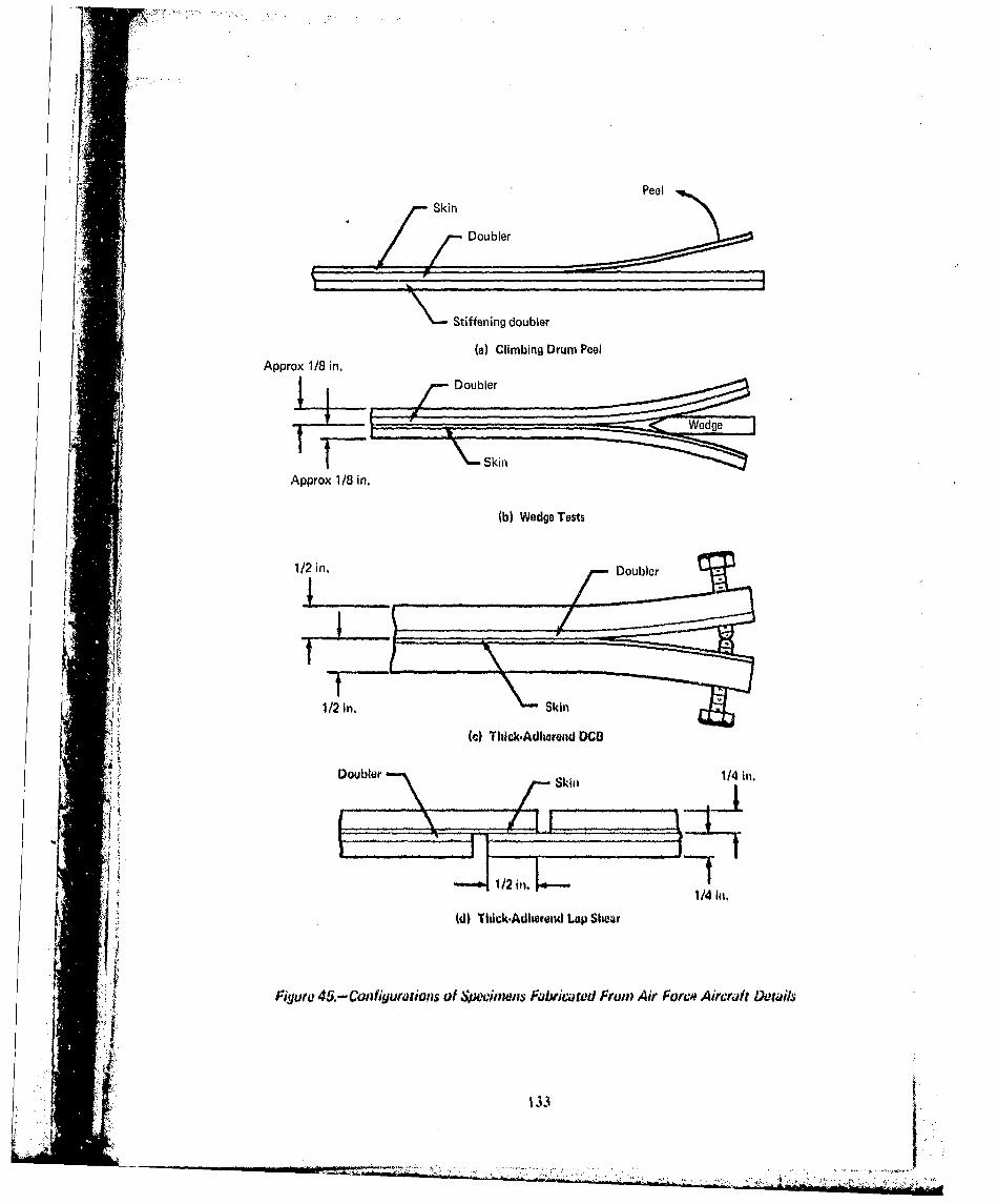
PeelSkin
Doubler
Stiffening doubler[ (a) Climbing Drum Peel
TSk-Approx 1/8 in.
(b) Wedge Tests
1/2 in.Dobe
1/2 in. Si
(c) Thlck.Adlwwend DCI3
Dobe 114 in.
1/4 in.
(d) Titick.Ad~tereM Lop Shear
Figure 45.-Con flyorauions of $oowimens Fabricated From: Air Forco? Aircraft Details

AF 111 adhesive bonds
-Wing panel (three specimens)
Upper wing panel between 5 and 6spoilers (one specimen)
Upper wing life raft door-. (three specimens)
4
L -. ~ - --- -- - -- -
2
Note; All failure modes adhesive
I I I i I I0 4 8 12 16 20 24 28
Exposure to 140OF/condensing humidity, weeks
(a) C-141 Bonded Panels Which Were Not Obviously Delaminated6-
AF 111 adhesive bonds
6-- Upper wing panel outboard of liferaft (two specimens)
... "-Upper wing panel, no. 1 (one specimen)
Upper wing panel, no. 2 (two specimens)
4 I
2
Now: All failure modes adhesive
Exposure to 140 F/condenisig humidity, wiovks
(b) C,141 Bunded Oularninated Panels
Figure 46.-Wudge Test Results of Soiximens MadhiMd From Air Force Aircraft
134
A

5- FM 61 adhesive bonds
T-38 outboard wing trailing edge(three specimens), delaminated
4--- F-5 outboard wing trailing edge no. 1(three specimens), no delaminationF-5 outboard wing trailing edge no. 2
S(three specimens), no delamination.3-
2V -
Note: All failure modes adhesive
I I I I I I I
0 4 8 12 16 20 24 28
Exposure to 160 F/condensing humidity, weeks
(W T-38 and F-5 Bonded Panels
FM 123-2 adhesive bonds
- T-38 landing gear strut door(five specimens), no delamination
--- C.5A aileron closeout door(four specimens), no delamination
-2
Note: All failure modes adhesive
4 8 12 16 20 24 28
Exposure to 140 F/coidensing humidity, weks
(d) T-38 and CSA Bonded Panals
Figure 46.-(Concluded)
S•:,•135J.

Sustained stress: 1500 psi
20
70% Adh15 65% Adh
10
o 20% adh
0
5
55% Adh
m t~ o I en
cn m Cn 1
0n 0 0
0 A:
AF I1I1 adlitsive jFM 61 adliusigo
14Y' Pit ondensinti Iitirnlduy 1 I GOO F/coeibjiisw humrnity
Visual assassmonti of arcraft ~jrti conditwion
A pw ou ond, 0 c4uastiwo.&blo bund, C. god bond
Fiyum 47.-Sustaiwwt-Stress TIhic4.Adheeenc Lup &W~r Tinwi-tu-F.Wurfj Results

10.2Upper range of data for 1800-cpm tests at 75F/
Lower range of data for 1800.cpm tests at 140F
10'4
Center of Hartman et al.
and Wei et al. data for
4! 7075-T6 at R = 0, distilled
U water, 0.4 and 5 cps, (from Hyatt et al, ref, 5)
z
10.6- • Center of Mostovoy et al.
for aluminum tefl. 4)
! lo1'7/-
.2 1.0 to 20IInlb/.2
*I , Figure 48--Comparison of Bonded Aluminum Fatigue Cra'k Growth Data With Published Data for
:1 Fatigue Ctack Growth in Aluminumn Alloys
V137
'il ,37

APPEN DIX ANONDESTRUCTIVE INSPECTION (NDI) OF BONDED TEST ASSEMBLIES
All bonded test assemblies fabricated for this program were nondestructively inspected (NDI)before fabricating test coupons. Ultrasonic through-transmission inspection with single-level and/or multilevel C-scan recording and low-voltage X-radiography (25 to 50 kV)were used onl all bonded assemblies. Neutron radiography was used on most of the honey-comb sandwich and on selected metal-to-metal assemblies. Results of these NDI evaluationsare shown in tables A-1 and A-2.
Low-voltage X-radiography, and especially neutron radiography, proved more definitive inidentifying voids and porosity than did the ultrasonic through-transmission for metal-to-metal assemblies. An example of neutron radiography showing some of the largest and most
numerous voids and porosity is shown in figure A-1.
The ultrasonic through-transmission data did not clearly show the same pattern of voids andporosity as did the radiographic methods, and in most cases did not suggest this condition.See table A-I. Part of this problem could have been due to bondline thickness variationswhich made it difficult to set the proper gates for the C-scan recorder, particularly whensingle-level recording was used.
Interpretation of NDI results for the honeycomb sandwich specimens was even more difficult,because of the double honeycomb sandwich and multiple bondlines. Again, neutron radio-graphy gave the most definition, but complete interpretation of the indications was notachieved. See table A-2.
Two examples call be cited where voids were responsible for reduced specimen performance:1) A 3/8-in. to 1/2-in, diameter void resulted in a premature stressed lap shear test failure(table 10 of text), and 2) several baseline lap shear results were lower than expected (table 4of text). None of the bonded assemblies from which the specimens were taken showedevidence of voids or porosity on the, X-radiographs or C-scan recordings.
Voids and/or porosity were evident in numerous )('11 and lap shear specimens after poslttstfracture, with some of these bondline discontiluities showing uip in the NI)i evaluation,towever, there was no evidence that these dicontinuities contributed to reduced durability.
It appear's that tlw only effect of voids and porosity is to increase tile local stress ill theconfined test area,
(Conclusions dh'awn from the assesst.mett of NLI results and subsequent dlurabmility tests are:
I . The radiographic N0)i methods, particularly neutron radiography. arc the 1iiostSdcfillitive lue0lns Of identifying Voids and 1XIIposity.
2. Voids and porosity that did not show uip in either ot' the N)I ulethods were present inbondlilles of test specillines,
3. 'Ii're W;as lio Correlation bet weer. NDI)l-ohkev'ed voidi and txrosity in blndeldksenlbhiCs aid adVel're siresse61d dulkribilityv test resultf,.
M N - - s'. L
" :•13,' 'ar.;•'• .t•,,t• t~l',4 ,• •.

t-#
,-.J• . ftz
3,
Note: Area shown represents approximately 20% of the AF 143 Bonded Assembly.
Figure A- 1.-Neutron Radiograph of Laminated 2024- T3 Clad Panel Section for
Thick-Adherend DCB Specimens Showing Voids in One or MoreBondlines
140

Table A- 1.-Nondestructive Inspection (ND I) of Bonded Metal-to-Metal Assemblies
Adhesive/primer Surface aNo. of Ultrasonic through-system Alloy treatmenit assemblies X-ray results transmission results
FM 123-2/BR 127 2024-T3 F 3 No anomalies Nothing definitiveclad C 3
P 4
2024-T3 F 3bare C 3 No anomalies Nothing definitive
p 6 No anomalies (5) Nothing definitive (5)Porosity (1) Spots on edge (1)
7075-TG F 2 No anomalies Nothing definitiveclad C 2 1
P 2 No anomalies
7075-T6 F 2 No anomalies (1)bare Adhesive qjap (1)
C 2 No anomnaliesP 2 No anomnalies (1) Nothing definitive
small porosity (1)
FM 123-2/BR 123 2024,T3 F I No anomnalies Nothing definitiveclad C 24
P 2I__ _
2024413 F 11-
P 2 No anotrinales Nothinqa def initivo
EA 0628/UR 127 2024,13 F 3 Nu oornoalies Nothinq drefinitivv
Clad C 3 4Nothingl dfinitivewP 6 Nothingj dof miitivt, (4)
V2. to I in-'spots (1)
K _________ ne I11/4-i'', spot (1)
N041* Nothintl defioinwv (3)bare spoltty aiea 11)
1wont~t lots Nothinq iteti t
P 12 No jooima liis 0 Il I No:In nqI( dotllw (i vi 11)
70/-1 F3 No atnwomais (2)
Clad Small voidsý wsviteuson (1) Notlionj detotimiye'liot w!~ayx
C3 Nowo~tnaties
P 3
P ( No, manontm Nothml gdefotinive
141

Table A-1.- (Concluded)
Adhesive/primer Surface No. of Ultrasonic through-system Alloy treatment assemblies X-ray results transmission results
AF 143/EC 3917 2024-T3 F 2 Porosity Nothing definitive
clad C 2 PorosityP 5 Porosity (2)
No anomalies (3)
2024-T3 F 2 Porosity
bare C 2 No anomalies (1)
Porosity (1)
P 4 No anomalies (3)
Porosity (1)
7075,T6 F 2 Porosity
clad C 2 Porosity
P 2 No anomalies Nothing definitive
7075,T6 F 2 No anomalies (1) Nothing definitive (1)bare Voids and porosity (1) 9 in, area in center (1)
C 2 No anomalies (1) Nothing definitive
Porosity (1)P 2 No anomalies (1) Nothinig definitive
Adhesive overlap (1)
PL 729,3/PL 728 2024.T3 F 2 Porosity Nothin~l definitivo
clad C 3 No anoma dtlios d TP 3 No anomalies (2) Nothing def initivo}
Small void 1/8 111, dia (1)
2024,13 F 2 Voids and porosity (1) Some discontin•litios (1
bare No anomalies ( 1) Nothing definitive ( 1)
4 C 3 No anomalles (2) Nothiniq delinitive (2)
P 4 No anomdles (1) Nothinq delinitivo (3)
Voids and porostty (3) S!oItIVt ater (I I
707646 F 2 No ainomilies Nothiriq dumniuvvclad C 2 t
P 2
"/015,!' F 3i
P 2 N ioe'alius Nolthlu dIolutovo
L P Atc
C cltifooic aciid llotnhi
P PhoW~wt a&cd ~alloieC
1 42
!:7

.- t . "c 11.k "iA
o -
C
o X o oCU U,
o c >c4 E E__ _ _
en( 0 0
o ) 0
S.,4-..U
0 E
CCii., ,-. -
5- inUI
-,aZ ,4..vi
k r-
14

0
at A C
B D
0
Figure 8-2.-Strain Gage Location on Thick-Adherend Lap-Shear Specimen
Each of the four specimens was tested on two different tensile test machines to determinestrain behavior under conditions of known uniaxial ksiding. Thes" two machines wc-re aTiniLus Olsen 30 000-lb tensile tester and a 20 000-lb Instron Universal Tests were miade by
incorporating the clevis tie rods from the jig into the test fixture and substituting widerclevises requiring a longer pin for the jig clevis tie rod.
Each of the strain-gaged specimens was then loaded into the loading fixture in the mannernormally used for environmental durability testing. The orientation of the specimens withinthe fixture is within the tube and partly up into the heli.=l spring, figure B-I.
Several repetitions of this loading were performed, anti slight modifications were made ontwo of the runs. One modification was to install a hemicylindrical washer between the nutand bottom plate: the other was to replace the safety belt by a cable.
The strains, in microinches per inch. indicated by each of the strain gages from two of thetensile tests and four of the loadin,_, fixture tests. are sho'wn in table B-I. These strains arefor a nominal applied 750 lb.
In table B-1. the sets ot strains from the tensile test miachines represent the widest variationsbetween numbers obtained from two different loadines or. the machines. I hese numbersrepresent practical axial loads obt:ainable.
145

Table B- 1.-Strain Gage Measurements of Thick-Adherend Lap-Shear Specimens
(microinches per inch)
Gagedesignationa 1A 1B 1C 1D 2B 2D 3B 3D 4B 4D
bTensile 1 147 101 110 136 116 143 108 162 139 140Tensile 2 151 98 119 159 83 168 129 149 121 155
CLoad 1 90 165 124 133 93 121 114 141 91 195
Load 2 129 97 150 168 90 175 115 147 90 204Load 3 82 78 198 182 69 183 122 139 75 214Load 4 90 73 192 181 .. .. .. .. 90 175
aGage designation: First character is specimen number
Second indicates gage positionbTensil 1: Instron with wide clevises
Tensile 2: Tinius Olsen with fixture clevisesCLoad 1: Standard loading of fixtureLoad 2: Standard loading of fixtureLoad 3: Installation of hemicylindrical washerLoad 4: Installation of hemicylindrical washer and
substitution of safety bolts by cables
By comparing the readings from a given gage (i.e., tensile I and 2 vs loads I 2, 31, and 4),it is evident that there were indeed nonaxial loads being applied to the specimen by thefixture. making it necessary to modify the fixture.
Since it has been noted with the fixtures that the springs tend to bend considerably out ofline when loaded and that there was little clearance inside the spring for the specimen, thefixture design was modified to accomplish the following:
I. Load the specimen outside of the spring
2. Restrain thle spring from bending out of line as much as )ossible
3. Compensate t•or small amounts of spring bending
In keeping with these objectives, the tube was lengthened to contain the entire specimen.a second alig•nment plate was added and the distance between the two alignment plateswas set to maintain both en(s of the spring. a hemicvlindrical washer was installed betweenthe nut and bottom plate, and the safety bolt was replaced by a cable. The modified fixtureis shown in figure B-3.
141

OD Hemnicylindrical washer
- ()Tensile stud (7.0 in.)
OSafety cable
Alignment plate stud bolt (12.50 in.)
(D Compression tube (6.5 in.)
OAlignment plates
Helical spring-i 000 lb capacity
Holes for visual
4. Figure 8,3.- Thiek-A dliwenid b- p*Shei Modified Luadhig Pixture
147

A prototype of this modified fixture was made as shown in figure B-3 except that twoexisting tubes were stacked together with a separator plate between in place of the single6.5-in. tube shown. The gaged specimens were tested in this modified jig, and their orienta-tion within the fixture was equivalent to that shown in figure BI, except for the specimenbeing contained within the tube. Strains indicated from four separate loadings to a nominal750 lb in the modified jig are shown in table B-2. Loads I through 4 represent loadings ofthe modified fixture in a manner equivalent to the usual method of loading the fixture.
Table B-2.-Strain Gage Measurements of Lap-Shear Specimens in Modified Loading Fixture
(microinches per inch)
Gagedesignation 1A 1B iC 1D 2B 2D 3B 3D 4B 4D
Load 1 154 99 93 140 98 140 107 141 122 134Load 2 160 104 110 153 99 145 111 143 123 146
Load 3 174 112 120 165 95 158 119 154 133 153Load 4 140 108 101 150 90 149 100 159 137 152
B.3 DISCUSSION AND CONCLUSIONS
Based on this program, it was concluded that the modified loading fixture represents asignificant improvement in loading reliability over the unmodified fixture. This improve-ment is shown by bending moments calculated for the tensile test data for both theunmodified and the modified fixtures. Assuming that all bending is uniaxial, the resultantprincipal strains are shown in tables B-1 and B-2.
Two natural bending moments are produced in the lap-shear specimens under uniaxialtension. These are given by the relations:
M a-c 2 _d BI-1a-c b-d - h
where I is the moment of inertia of the specimen at an unnotched cross section, h is thespecimen height at an unnotched cross section, and a and Ohd are given by:
A-C =B-Dac = 7, = ) E (2)
148
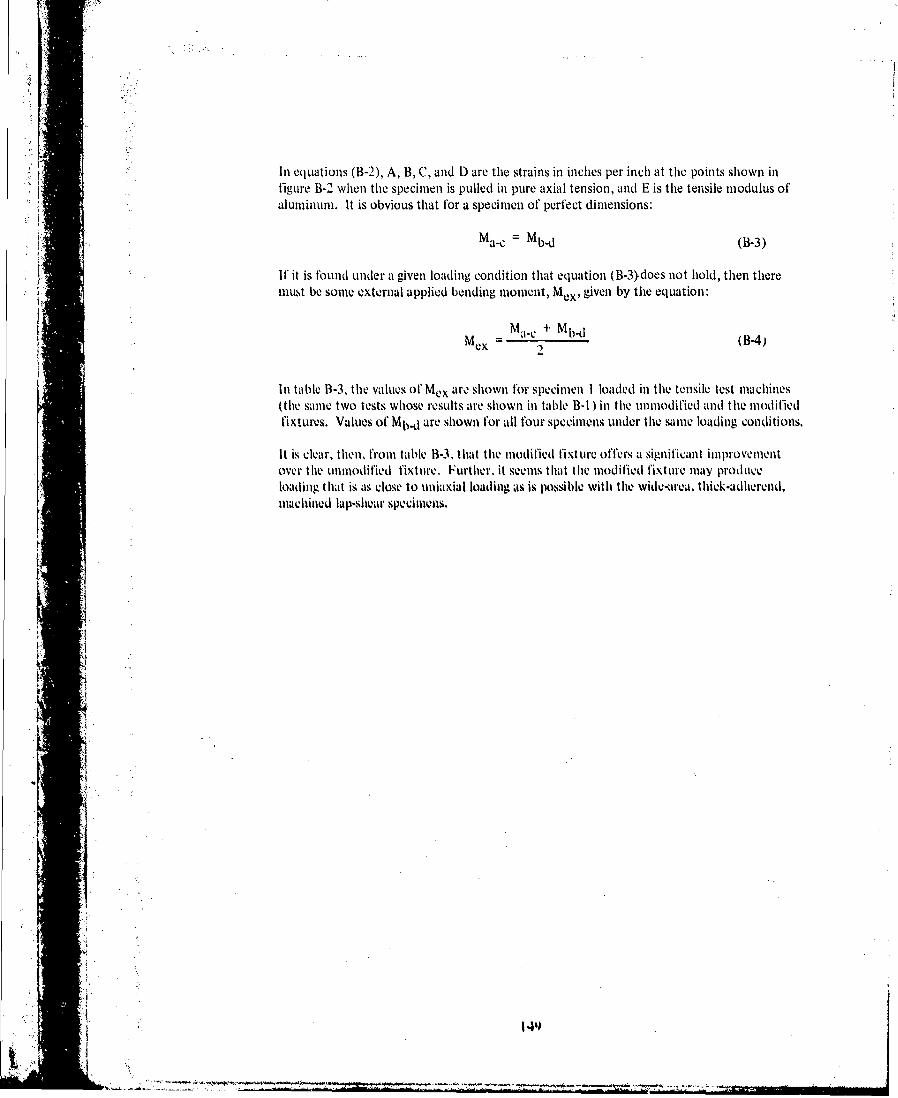
In equations (B-2), A, B, C, and D are the strains in inches per inch at the points shown infigure B-2 when the specimen is pulled in pure axial tension, and E is the tensile modulus ofaluminum. It is obvious that for a specimen of perfect dimensions:
Ma-c Mb-d (B-3)
If it is olund under a given loading condition that equation (B-3),does not hold, then theremust be some external applied bending moment, Mex, given by the equation:
M a. Mb -dMex= c M (B-4)
In table B-3, the values of Mex arc shown for specimen I loaded in the tensile test machines(the same two tests whose results are shown in table B-I ) in the unmodified and the modifiedfixtures. Values of Mb-d are shown for all four specimens under the same loading conditions.
It is clear, then, from table 13-3, that the modified fixture offers a significant improvementover the unmodified fixture. Further, it seems that the modified fixture may prodtuceloading that is as close to uniaxial loading as is possible with the wide-area, thick-adherend,machined lap-shear specimens.
A 4'•

(0
rCNC(O
r, D Cd ) C)(00M LC LO U IT
cCN .0 LO com NCN r- M
E
0C Ln O 0O
ZI + INI
co LO ro- CD (Vocu +y +++ 17 I - ' RL9
CL.QLa 0 - coC o (0I 1
CC
I.+
I C nr9 aI OC 00 qCm 6 1: 1 l l
APPENDIX CWEDGE TEST FOR ADHESIVE BONDED SURFACE
DURABILITY OF ALUMINUM 1
C.1 SCOPE
This test simulates inl a qualitative manner the forces and effects onl anl adhesive bonld jointat mietal-adhiesivelpriimer interface. it hias provedl to be highly reliable inl determing andpredicting the environmental durability of adhierend su~rface preparations. Tile method hiasproved to be correlatable with service performance inl a manner that is MUChI more reliablethan conventional1 lap-shiear or peel tests.
C.2 SUMMARY OF METHOD
A wedge is forced into thle hondline of a flat bonded aluminum specimen. thereby creatinga tensile stress inl the region ot the resulting cr~ack tip. The stressed specimen is eXPOSed toanl aqlueous environment, usually at anil elevated temperature, or to anl appropriate environl-mlent relev~ant to thle ulse oft'i le bonded structure. The resulting crack growth wvithi time andfailuire modeLIs is then evailuated. Variations inl adherend surface quality are easily observable
WWiII the specimenols are openled- -lorceably. iI necessary- -at thle test conclusion.
t C.3 SIGNIFICANCE
The test is qutalitative only butl is Very discrim~inlatingi ill determinling variations ill adherenldsurf~ave prepa"rat ionl paramieters and adhelsive enivironlmental durability. Ill addition to deter-mi ning crack growvthI rate and assigning a value to it, ( lie failure mudoke should be evalulatedanld reported. lVor example, coheivesive siet-rine orprm-tadhedlairsshould lie nolted after opV111iiig the spechimen ait thle conclusionl Of theV period.
CA4 APPAR~ATUS
Tlhe floig.paausis used:
I . A S to 30 power niagmuller tprelera lly stereo bimiovular)
2.Sharp. pointedl niarlsing stylus mnid/or trialigular file
J., Stainmless steel or alimimmumm wedges
j 4. Small wa~le gramduatedl i4% millimetems or hullkretkilo ol all immel
:1 ~C-45 TEST SPEICIMN1;
A mimiinutmmm ill live 2.i4- byv 1 S.2-emim I 1- by n. fr'immmNlomm .1 sammsgle amN,%4.Iibiy shmall 1w
ISublummned it) ASI I NI Comnimittev D1)I4

C.6 CONDITIONING
Tile specimens may be, exposed to any environment appropriate to the bonided structurebeing represented;e.g liumidity, heat, thermal shock, salt spray, etc. For most apphications,however, water is the most deleterious environment to thle poly mer-adhIe]en ittie.atypical environment commonly used is 49TC (I 200'F) and condensing humidity. IfV consistency with other stressed durability testing requirements is desired, then the followingconditions canl be used:
* For 1210C (250'F) curing adhesives: 600C (140'F) and 95% to 100%4 RH
* For 1770C (350"F) and higher curing adheCsives: 71 0C (I160'F) and 95% to 100% RH
C.7 PROCEDURE
1. Prepare the surfaces of a piece of 15.24- by 1 5.24- by 0.32-cm (6- by 6- by 0. 1 25-in.)alumlinuml, using a surfaice treatment process appropriate for thle test requirements,
2. Prime tile f~aying surface of each panlel, apply thle adhlesive. assemble thle paniels., andcure thle adliesive as required by thle appropriate specification. (For later convenienceinl inserting a wedge, a separation film may be inserted along one edge of the assemblyas shown inl fig. C-I . or thle adhesive may be om1itted along onle edge.)
31. Cut thle test assembly inito five I -in,-wide test specimniis as shown inl figure C-I1. Atleast onle cut Cki[-Q of each spieclimen shAll have a surface finlish of 125 P inl. or bet e..There shall ble not burrs or smearinig of adhevrend miaterial onto tlike bioidliiv. D~o notovei'lteat oif damage thev biond Whenk Cutting or finlishing,
5 ~~~4. Appropri~ately identify all test speimenios inl sue'h a manner thatl testing inl a hligh111 h1midlity enivironlment will nlot destroy thle identification markings. tA ppro.priately
;j Il~~~poitioned idlentifikation Markings canl tic madle onl lte 0- by 0-in. (15,24- by 1 5.24-cm)
patiolse prior it) s.urface pvImpniitioII provessinig.1
S. (Cmack onte 0end of eaikl test speclimen bly inlsertingp 1- wedge .1% showil in figure C-Iinsert lihe wvedge by using .1 pushing foirce or several relatively ligh pý wt a ha11mer-
*ingr device, if)0 N07 insert lie Wedge Withi a Sililgtk -ýrikillg bllow, Whenl ilsertingwedlge. 1)0 AVOT hldtl specilimen inl any Way I hiat Will restr-aill thIe inlitial cIaciPosit ion thle wedge Nio tialtihe bMunt end0 and idvs aIre aproinaet Ish Witlli hIlotof thle spieciimen. 4Ill anly use til anl aimili'arY tool to precrIack a test spC11eime to
facilitate illsvrtiomi ofk a edge, tile V-lenll of preniackillg must ki less thal that whlichis Amused lly inlsertionl of like wvede.)
6. Usinig S tot 311 111wer nanliat ionan adequlate i lhl ntiaoll, Ilocate thle lit All lthetill onithe I25P ni, finuih edge ot cacti s'cm .I Inhis t Ili p41inti tathet Iiv 11411
the wvedge wherie thke spec111ime thte adheisive. prinmer,a til.o atieimndo has sel'arated.Usnnaline 1111 SVms1 Ar scribe. mark thel locationl om one .mtiaendl' eklpe, lithe Speeneiilis ito Ie used in saIlt spay orl All 1h0r enlvirnmilenit e\p~etd to' he V011 41 ndJI liabtle itoobbicitate lthe 1mark, devepln tike scibell Illnk Witlli a 16aitagil~i lite,
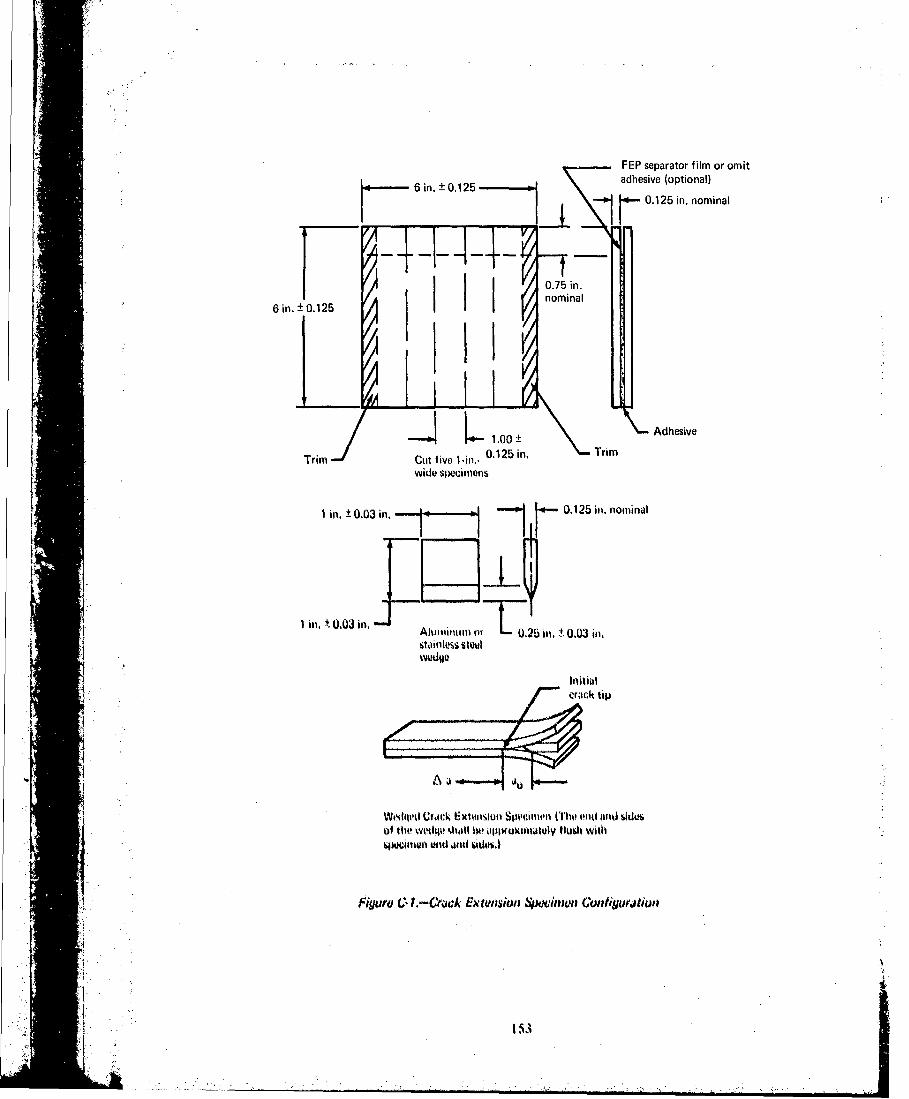

7. Expose the wedged specimens to the environment required by the appropriatespecification.
8. Remove the specimens from the environment, and within 15 minutes mark the locationof the tip of tht crack after exposure in the same manner as in step 6.
* 9. Measure tile crack extension of each specimen to (0.025 cm) 0.01 in. or less precisionto determine that the crack extension is more or less than the specified amountrequired by the appropriate specification.
10. At the conclusion of the test, forceably open the specimen and note the failure mode
of the test section.
C.8 INTERPRETATION OF RESULTS
The crack extension Aa and the crack extension failure mode (i.e., adhesive failure at theinterface or cOhesive within the adhesive are reported.
Tihe initial crack length a0 , the crack extension Aa, and the crack extension tfilure mode areall a function of the adhesive/primer systems being considered and the adherend surfacetreatment, Because of these variables, the acceptance criteria for a bonded system of interestwill have to 5e established. The following is an example of an acceptance criterion for 1 21TQ( 2 50' F) curing high-peel modified epoxy structural adhesives:
Ten specimens, representing two individual bonded test assemblies, are tested. Typically,good duribility surface preparation is evidenced by no individual specimen having a cracklength exceeding 1) nun (0.75 in.) and tile average of all specimens kving not over (.3 mm(0. 25 inl.).
C.9 REPORT ON RESULTS
I. Report the original crack lenith alnd tIle crack extentsion at the eud of Various ti6n1intervals, such as I, 4, 8, 24 hours. 7. 30 days,
2. Also report the failure mode as I 0 c"' cohesive. Il0,'; adhesive, or 50', adhesive. etc.
J ,
" 154
• , , , ,, nl,_.._jt•. . . .. .... T y .•::.;3-k;•, " • ,k. I I ,' . . .. . .