Embed Size (px)
Citation preview
Media Dock Receiver 1000
(MDR-1000) Quick Reference Guide
009-0470-00 MDR-1000-05
Copyright © 2012 Savant Systems LLC, SAVANT and RacePoint Blueprint are trademarks of Savant Systems, LLC. All brand names, product names and trademarks are the property of their respective owners. Savant Systems, LLC reserves the right to change product specifications without notice.
Savant Confidential and Proprietary
75 Perseverance Way, Hyannis, MA 02601 Phone 508.683.2500 Fax 508.683.2600 SavantSystems.com
The Savant® Media Dock Receiver (MDR-1000) Quick Reference Guide provides the information necessary to install the Media Dock Receiver with the On-Wall Media and Desktop Media Docking stations for Apple® iOS Devices.
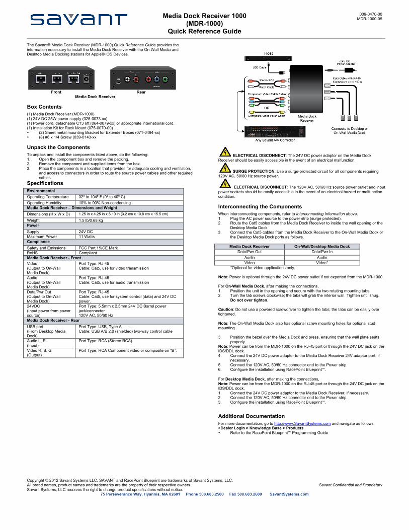
Front Rear
Media Dock Receiver Box Contents (1) Media Dock Receiver (MDR-1000) (1) 24V DC 25W power supply (025-0073-xx) (1) Power cord, detachable C13 6ft (064-0079-xx) or appropriate international cord. (1) Installation Kit for Rack Mount (075-0070-00) • (2) Sheet metal mounting Bracket for Extender Boxes (071-0494-xx) • (8) #6 x 1/4 Screw (039-0143-xx Unpack the Components To unpack and install the components listed above, do the following: 1. Open the component box and remove the packing. 2. Remove the component and supplied items from the box. 3. Place the components in a location that provides for adequate cooling and ventilation,
and access to connectors in order to route the source power cables and other required cables.
Specifications Environmental Operating Temperature 32º to 104º F (0º to 40º C) Operating Humidity 10% to 90% Non-condensing Media Dock Receiver – Dimensions and Weight Dimensions (H x W x D) 1.25 in x 4.25 in x 6.10 in (3.2 cm x 10.8 cm x 15.5 cm)
Weight 1.5 lb/0.68 kg Power Supply 24V DC Maximum Power 11 Watts Compliance Safety and Emissions FCC Part 15/CE Mark RoHS Compliant Media Dock Receiver - Front Video (Output to On-Wall Media Dock)
Port Type: RJ-45 Cable: Cat5, use for video transmission
Audio (Output to On-Wall Media Dock)
Port Type: RJ-45 Cable: Cat5, use for audio transmission
Data/Pwr Out (Output to On-Wall Media Dock)
Port Type: RJ-45 Cable: Cat5, use for system control (data) and 24V DC power.
24VDC (Input power from power source)
Port Type: 5.5mm x 2.5mm 24V DC Barrel power jack/connector 120V AC, 50/60 Hz
Media Dock Receiver - Rear USB port (From Desktop Media Dock)
Port Type: USB, Type A Cable: USB A/B 2.0 (shielded) two-way control cable
Audio L, R (Input)
Port Type: RCA (Stereo RCA)
Video R, B, G (Output)
Port Type: RCA Component video or composite on “B”.
ELECTRICAL DISCONNECT: The 24V DC power adaptor on the Media Dock Receiver should be easily accessible in the event of an electrical malfunction.
SURGE PROTECTION: Use a surge-protected circuit for all components requiring 120V AC, 50/60 Hz source power.
ELECTRICAL DISCONNECT: The 120V AC, 50/60 Hz source power outlet and input power sockets should be easily accessible in the event of an electrical hazard or malfunction condition. Interconnecting the Components When interconnecting components, refer to Interconnecting Information above. 1. Plug the AC power source to the power strip (surge protected). 2. Route the Cat5 cables from the Media Dock Receiver to inside the wall opening or the
Desktop Media Dock. 3. Connect the Cat5 cables from the Media Dock Receiver to the On-Wall Media Dock or
the Desktop Media Dock ports as follows.
Media Dock Receiver On-Wall/Desktop Media Dock Data/Pwr Out Data/Pwr In
Audio Audio Video Video*
*Optional for video applications only. Note: Power is optional through the 24V DC power outlet if not exported from the MDR-1000. For On-Wall Media Dock, after making the connections, 1. Position the unit in the opening and secure with the two rotating mounting tabs. 2. Turn the tab screws clockwise; the tabs will grab the interior wall. Tighten until snug.
Do not over tighten.
Caution: Do not use a powered screwdriver to tighten the tabs; the tabs can be easily over tightened.
Note: The On-Wall Media Dock also has optional screw mounting holes for optional stud mounting.
3. Position the bezel over the Media Dock and press, ensuring that the wall plate seats
properly. Note: Power can be from the MDR-1000 on the RJ-45 port or through the 24V DC jack on the IDS/DDL dock. 4. Connect the 24V DC power adaptor to the Media Dock Receiver 24V adaptor port, if
necessary. 5. Connect the 120V AC, 50/60 Hz connector end to the Power strip. 6. Configure the installation using RacePoint Blueprint™.
For Desktop Media Dock, after making the connections, Note: Power can be from the MDR-1000 on the RJ-45 port or through the 24V DC jack on the IDS/DDL dock. 1. Connect the 24V DC power adaptor to the Media Dock Receiver, if necessary. 2. Connect the 120V AC, 50/60 Hz connector end to the Power strip. 3. Configure the installation using RacePoint Blueprint™. Additional Documentation For more documentation, go to http://www.SavantSystems.com and navigate as follows: >Dealer Login > Knowledge Base > Products • Refer to the RacePoint Blueprint™ Programming Guide


![DOCK 6.1 User Manualwiki.docking.org/images/1/16/Dock61.pdf · 09/02/2007 · [user@dock ~] cd test [user@dock ~] make clean [user@dock ~] make test This directory contains the DOCK](https://img.dokumen.tips/doc/110x75/5f6d68232a88f91218253ef3/dock-61-user-09022007-userdock-cd-test-userdock-make-clean-userdock.jpg)