Embed Size (px)
Citation preview

SECTION 6B
GROUTING TO IMPROVEFOUNDATION SOILJAMES WARNER
6B.1 INTRODUCTION 6.3426B.1.1 Foreign Development 6.3436B.1.2 U.S. Development 6.343
6B.2 WHY GROUT IN SOIL? 6.3456B.2.1 Densification/Prevent or
Arrest Settlement 6.3466B.2.2 Soil Solidification/Increase
Cohesion of Granular Soils 6.346
6B.2.3 Reduce Permeability/Water Control 6.347
6B.2.4 Stabilize/Reduce Expansion of Clay Soils 6.347
6B.2.5 Filling Large Voids/ Compensating for Lost Ground 6.348
6B.3 TYPES AND PROPERTIES OF GROUT 6.350
6B.3.1 Fluids/Solutions 6.3506B.3.2 Fluid Suspensions 6.3606B.3.3 Mortar-like Low Mobility
Grouts 6.3646B.4 GROUT RHEOLOGY 6.364
6B.4.1 Mobility 6.3676B.4.2 Penetrability 6.3686B.4.3 Cohesion 6.3726B.4.4 Bleed 6.3726B.4.5 Setting Time 6.3736B.4.6 Solubility 6.373
6B.5 TESTS FOR EVALUATION OF GROUTS 6.374
6B.5.1 Flow Cones 6.3746B.5.2 Specific Gravity 6.3756B.5.3 Evaluation of Bleed 6.3766B.5.4 Pressure Filtration 6.3766B.5.5 Slump 6.3786B.5.6 Strength Tests 6.378
6B.6 TYPES OF GROUTING 6.379
6.341
6B.6.1 Fracture/Claquage Grouting 6.379
6B.6.2 Compaction Grouting 6.3836B.6.3 Permeation Grouting 6.4246B.6.4 Jet (Replacement)
Grouting 6.4476B.6.5 Replacement/Compensation/
Fill Grouting 6.4546B.6.6 Groutjacking 6.457
6B.7 SPECIAL CONSTRUCTION TECHNIQUES INVOLVING GROUTING 6.458
6B.7.1 Mixed in Place Piles 6.4586B.7.2 Auger-cast Piles 6.4606B.7.3 Deep Soil Mixing 6.4616B.7.4 Micropiles 6.4626B.7.5 Posttensioned Soil
Anchors 6.4626B.8 INJECTION FUNDAMENTALS
6.4626B.8.1 Injection Pressure 6.4636B.8.2 Pumping Rate 6.4646B.8.3 Pressure Behavior 6.4686B.8.4 Pressure-Volume
Relationship 6.4716B.9 PLANNING A GROUTING
PROGRAM 6.4716B.9.1 What are the
Objectives? 6.4726B.9.2 Access/Surface
Improvements 6.4736B.9.3 Subsurface Structures and
Utilities 6.4746B.10 CONDITION ASSESSMENT/
GEOLOGICAL CONSIDERATIONS 6.474
6B.10.1 Soil Type and Properties 6.476
Source: PRACTICAL FOUNDATION ENGINEERING HANDBOOK
Downloaded from Digital Engineering Library @ McGraw-Hill (www.digitalengineeringlibrary.com)Copyright © 2004 The McGraw-Hill Companies. All rights reserved.
Any use is subject to the Terms of Use as given at the website.

6B.10.2 Formation Stratigraphy 6.479
6B.10.3 Groundwater 6.4806B.11 INJECTION MONITORING AND
EVALUATION 6.4806B.11.1 Injection Behavior 6.4816B.11.2 Site Surveillance 6.4826B.11.3 Injection Records 6.488
6B.1 INTRODUCTION
Geotechnical pressure grouting consists of forcing grout under pressure into a subsurface forma-tion. The grout can be a liquid solution, fluid suspension, slurry, or of a stiff mortar-like consistency.It will generally harden at some point after injection so as to become immobile. Prior to the last fewdecades, most grouting was done to fill discontinuities in rock, with the primary purpose of reduc-ing water movement through the formation. Now, in addition to water control, grouting is also ex-tensively used to strengthen soil, either permanently or temporarily as an aid to construction.
Grouting is not new. In fact, records abound of grouting projects throughout the 1800s and evenprior to that. Most of the early work involved injection of aqueous suspensions or slurries, oftencontaining cement, lime, or clay, into joints and seams in the bedrock underlying dams in order toreduce water leakage. As early practice involved filling of seams or voids, the grout had to be veryflowable, and the maximum particle size considerably smaller than the thickness of the particulardiscontinuity to be filled. Because the pore spaces in soils are generally much smaller than typicalrock joints, injection of particulate grout had limited success in soil.
Accordingly, low-viscosity chemical “solution” grouts, which could permeate soil formationsand chemically harden, were developed. In 1887, a patent was issued to Jeziorski for a sodium sili-cate based formulation, which could be mixed on-site and injected. Unfortunately, the chemicalswould react soon after mixing, requiring very rapid injection, and all too often, would harden in theinjection hoses and delivery system. This limitation restricted the application of these early grouts insoils.
To overcome the problem of early hardening in the delivery system, Hugo Joosten, a Dutch min-ing engineer, developed a two-shot sodium silicate based grout system, which was patented in theUnited States in 1925. Therein, the sodium silicate base chemical was first injected into the soil, fol-lowed by injection of a reactant chemical, commonly calcium chloride, which would cause the sili-cate to harden. Although Joosten’s system was used until the late 1960’s, difficulty in achievingcomplete mixing of the two components in the ground discouraged it’s widespread use.
In the 1950s, large chemical suppliers started marketing a variety of solution grout systems, pri-marily focused at the reduction of water movement through soils but for soil strengthening applica-tions as well. Many of those systems are no longer available due to environmental restrictions oreconomic considerations. Although commercially available chemical grout systems remain avail-able, sodium silicate based grouts are the most widely used, especially for soil strengthening work.The earlier limitations of rapid setting have been overcome in modern formulations. Many differentreactant systems for silicate base grouts are readily available, and it is common for the grouts to beproportioned on the job site by the specialist contractor, using his own particular reactant systemand formulation. There are also a number of proprietary sodium silicate base grout systems com-mercially available. For water control grouting, more sophisticated chemistry is generally involved,and commercially available formulations are almost exclusively used.
6.342 SOIL IMPROVEMENT AND STABILIZATION
6B.11.4 Be Prepared for Changes! 6.492
6B.11.5 Verification of the Effectiveness 6.500
6B.11.6 Grouting Specifications and Contracts 6.503
6B.12 SOME FINAL THOUGHTS 6.507References and Further Reading 6.509
Downloaded from Digital Engineering Library @ McGraw-Hill (www.digitalengineeringlibrary.com)Copyright © 2004 The McGraw-Hill Companies. All rights reserved.
Any use is subject to the Terms of Use as given at the website.
GROUTING TO IMPROVE FOUNDATION SOIL

Another significant contribution to the current state of the art in grouting of soils was the devel-opment of the “mudjack” machine in 1933. The original objective of the machine was the filling ofvoids under, and raising of, settled concrete pavement. As conceived, a mixture of “loam” or clayeysoil was used. As experience with the machine was gained, it was found that the addition of portlandcement resulted in a stronger and more durable grout material. Likewise, it was found that by vary-ing the consistency of the grout, a wider range of work could be accomplished. As a natural out-growth of their work, some of the more inventive operators of the mudjack attempted stabilizationof the soil by various means, including pumping of relatively stiff mud mixes into predrilled holes.Although early work was performed on a somewhat “hit or miss” basis, and with little engineeringinput, a great deal of knowledge was gained and such work was actually a forerunner of the “com-paction grouting” process that is now widely practiced.
In the 1940’s it was found that mixing a source of calcium with clay soil was beneficial tostrengthen and/or reduce the expansiveness of clay. High calcium hydrated lime became the materi-al of choice for such mixing, due to its economy and wide availability. The practical depth for phys-ical mixing was limited however, and a method for deeper mixing was needed. This resulted in useof pressure injection of lime slurries, using grouting techniques. Lime injection continues to be uti-lized, primarily in geographic areas where swelling clay soils predominate.
6B.1.1 Foreign Development
A very significant amount of our present grouting knowledge is the result of foreign development,primarily from the European countries, where extensive use of both solution chemical grouts andparticulate suspension grouts has occurred. Unlike American practice, much European work is per-formed on a design–build basis, and very large projects are commonplace. This has resulted in largemultidiscipline firms possessing the capability to perform research and development, design engi-neering, and the actual construction, as well as design–build and maintain the very specializedequipment often utilized. Such ability to integrate the various disciplines combined with strong fi-nancial capability has resulted in many technical advances. There has, however, been reluctance onthe part of such firms to share their knowledge, and in fact, it is not unusual for their proposals to becompletely void of any mention as to the exact procedures or materials to be used, but rather onlythe end product to be obtained.
Unique to European work is the use of large central grout plants (Figure 6B.1), often containinga number of different types of mixing and pumping units. Such plants are nearly always providedwith automated continuous monitoring and recording equipment, and the operation is usually underthe direct supervision of a professional engineer. With exception of techniques that rely on the useof massive equipment such as jet grouting, the European philosophy for grouting has remainedlargely unchanged in recent times, and although improved and refined, solution and fluid suspen-sion grouts continue to be used almost exclusively.
6B.1.2 U.S. Development
Contrary to the European experience, development of soil grouting in the United States was some-what erratic and primarily the work of small, widely dispersed specialty contractors. The more com-mon grouting of rock for dam foundations was under the control of one of three large federal gov-ernment agencies: The Army Corps of Engineers, Bureau of Reclamation, and Tennessee ValleyAuthority. These agencies generally designed and supervised their grouting operations in-house, tothe point that the contractors basically furnished only labor, equipment, and materials, performingthe work strictly as directed by the agency. This effectively discouraged research or development bythe contractors, resulting in little interaction between those contractors doing the more traditionaldam foundations and those performing work other than dam-related, which included virtually allgrouting of foundation soil. Unfortunately, a shroud of secrecy, often embraced by the latter group,
6.343GROUTING TO IMPROVE FOUNDATION SOIL
Downloaded from Digital Engineering Library @ McGraw-Hill (www.digitalengineeringlibrary.com)Copyright © 2004 The McGraw-Hill Companies. All rights reserved.
Any use is subject to the Terms of Use as given at the website.
GROUTING TO IMPROVE FOUNDATION SOIL

prevented the sharing of experiences, so that neither widespread knowledge nor use of their devel-opments occurred.
It is only within the last few decades that extensive knowledge of grouting technology has be-come available. A major contributor to this change has no doubt been the week-long Short Courseon Fundamentals of Grouting, now sponsored by the University of Florida and held annually eachyear since 1980. Additionally, the American Society of Civil Engineers Geo-Institute has sponsoredspecialty conferences, as well as a number of sessions, at their gathering, on grouting. Sadly howev-er, despite the dissemination and sharing of knowledge, some firms continue to maintain a “shroudof secrecy” in an effort to convey the idea that only they are capable of the “magic touch.” Evenworse is the sponsorship of publications and seminars that often provide incorrect information, fa-vorable only to the sponsor. Such marketing efforts, often lack technical accuracy and incorrect in-formation is frequently provided. Whereas foundation grouting knowledge, is now fairly well devel-oped, many practitioners, especially design engineers, remain unaware and/or misinformed, ofcertain well-established technology.
6.344 SOIL IMPROVEMENT AND STABILIZATION
FIGURE 6B.1 Large European central grout plant.
Downloaded from Digital Engineering Library @ McGraw-Hill (www.digitalengineeringlibrary.com)Copyright © 2004 The McGraw-Hill Companies. All rights reserved.
Any use is subject to the Terms of Use as given at the website.
GROUTING TO IMPROVE FOUNDATION SOIL

6B.2 WHY GROUT IN SOIL?
There are many reasons for grouting in soil, but the most frequent is to strengthen it. This can be ac-complished through densification, increasing the cohesion of granular soils, or in the case of clay,altering the chemistry. Another major area of work involves control of subsurface movements of wa-ter and reducing the permeability of soil.
6B.2.1 Densification to Prevent or Arrest Settlement and Mitigate Liquefaction
In the United States, compaction grouting is the most frequently used procedure for densification ofexisting soils. It is widely used for arresting settlement of structures of all types (see Figure 6B.2). Italso is widely used for predensification of faulty soils, prior to construction, as well as soil densifi-cation under existing structures for mitigation of the liquefaction potential during earthquakes. Anextension of compaction grouting, which involves essentially the same equipment and grout mix-tures, is “groutjacking,” which can accurately raise or level settled structures and effect other im-provements.
Compaction grouting is uniquely American and is the only major grouting technique to origi-nate in the United States. Its early development was in California in the mid to late 1950s. It isonly within the last few decades however, that the procedure has been extensively used. Althoughmuch research has occurred and the technology is well documented, some practitioners fail to uti-lize the proper procedures, resulting in improper and often incompetent performance. It is unfor-
6.345GROUTING TO IMPROVE FOUNDATION SOIL
FIGURE 6B.2 Compaction grouting under a structure to correct settlement damage.
Downloaded from Digital Engineering Library @ McGraw-Hill (www.digitalengineeringlibrary.com)Copyright © 2004 The McGraw-Hill Companies. All rights reserved.
Any use is subject to the Terms of Use as given at the website.
GROUTING TO IMPROVE FOUNDATION SOIL

tunate that such poor performance has in many instances resulted in limited effectiveness, andsometimes in actual damage to the structure it was meant to repair. Although the greatest use ofcompaction grouting remains in the United States, it is now recognized and used worldwide, es-pecially in Asia.
6B.2.2 Soil Solidification to Increase Cohesion of Granular Soils
Another form of strengthening is the solidification of sandy soils, wherein the individual grains arebonded together with a chemical solution or a fluid suspension grout (Figure 6B.3). There are a va-riety of chemical solution grouts, but they all work in essentially in the same manner. A base materi-al, which usually represents the majority of the final mix and is often diluted with water, is com-bined with one or more reactant materials. The base component is usually fluid, whereas thereactants can be either liquid or powder, depending upon the individual grout formulation. At someperiod of time after mixing the base and reactants together, setting occurs, and the injected solutionturns either to a foam, gel, or solid state. The setting time can be instantaneous to several hours, de-pending upon the individual system used and the environment at the work site.
Many chemical grouts are mixed and pumped as single solutions, whereas the different compo-nents of others are individually pumped and stream mixed at the injection point. There are severalmanufacturers of proprietary chemical grout formulations, especially those used for control of wa-ter movement within the soil or into underground substructures. For strengthening applications, es-pecially where large quantities of grout are required, however, many specialty contractors tend topurchase the individual chemical components separately and mix them on the job site near the pointof injection. Although some specialists tend to represent their formulations as something very spe-cial and “proprietary” (a word greatly overused, in the writer’s opinion), the vast majority of groutsnow used for strengthening of soil throughout the world involve sodium silicate as the base materi-
6.346 SOIL IMPROVEMENT AND STABILIZATION
FIGURE 6B.3 Sandy soil solidified to a solid mass.
Downloaded from Digital Engineering Library @ McGraw-Hill (www.digitalengineeringlibrary.com)Copyright © 2004 The McGraw-Hill Companies. All rights reserved.
Any use is subject to the Terms of Use as given at the website.
GROUTING TO IMPROVE FOUNDATION SOIL

al. There are however, a wide variety of different reactant systems, most of which are well knownand readily available.
With the increasing availability of ultrafine cements, many of which are able to readily penetratethe pores of even fine sands, suspension grouts of these cements are increasingly being used for soilsolidification. They usually result in a stronger and more predictable solidified mass than do thechemical solution grouts, and are often less costly to apply. Also, unlike many chemical grouts, theydo not lose strength over time.
European practice for soil strengthening continues to favor chemical solution and/or cementi-tious suspension grouts. Because solution grouts are usually much more expensive than their com-mon cementitious counterparts, there is a natural tendency to use the latter if feasible. Recognizingthat their grain size often exceeds that of the soil pore space, applicators have developed highly re-fined injection procedures wherein a discreet amount of grout is placed at regular intervals along agrout hole. The grout tends to fracture the soil but remains near its intended location, as only a smallamount is injected at each interval. The amount of densification that results from any single hole islimited, as the quantities of grout injected are usually small and considerably less than typically usedin compaction grouting. This is necessary, as once grout has created a fracture in the soil, it is virtu-ally impossible to control its deposition distance or direction. Relatively close spacing of the groutholes and limitation of the grout quantity at each hole location is thus imperative in order to main-tain control of the injection.
6B.2.3 Reduce Permeability, Water Control
Historically, cementitious suspension grouts have been used to stop the flow of water through cracksand joints in rock. The pore size of most soils, however, is significantly smaller than the width oftypical rock joints, and except in the case of coarse sands and gravels, it is insufficient for intrusionof a common cementitious, particulate grout. Thus, water control in soils is almost always accom-plished with either chemical solution grouts or suspensions based on ultrafine cement. Whereashard rigid chemical gels are preferable for strengthening applications, some flexibility is usually de-sirable in water control work, and thus different chemical grout systems are in order. Dilution of thegrout with groundwater is always a concern, and where rapid flow of the water occurs, the groutmust be resistant to being washed away as well. This often means use of a rapidly setting grout. Avariety of such materials are widely available that provide instantaneous setting, as shown in Figure6B.4. These grouts are usually more chemically complex than those used for strengthening of soil.Some formulations present health risks and require special handling. They are thus most often ob-tained as proprietary systems from specialty grout producers.
6B.2.4 Stabilize and Reduce Expansion of Clay Soils
Unlike granular soils, clay consists of microscopically small, flat plate-like flakes. Clay platelets aregenerally colloidal in size, which means that they will float rather than sink in water. Water betweenthe individual plates, thus contributes significantly to the volume of a clay soil. Because of theminute size of the individual particles, the movement of water in clays is very slow, and consolida-tion of clay soils, which results from expulsion of the water component, occurs slowly. Changes inthe water content of clays can produce either expansion or shrinkage of the soil.
Mixing a source of cations such as calcium with clay has been shown to stabilize the water con-tent, thus producing a more stable soil material. The most frequently used calcium source is lime,which is available in two forms—quicklime and hydrated lime. When these materials are physicallymixed with clay soil, base exchange and pozzolamic reactions occur, which are fairly well under-stood. When lime slurries are injected at depth (Figure 6B.5), beneficial results are obtained; how-ever the exact response is not predictable. Lime injection has been practiced in the United States for
6.347GROUTING TO IMPROVE FOUNDATION SOIL
Downloaded from Digital Engineering Library @ McGraw-Hill (www.digitalengineeringlibrary.com)Copyright © 2004 The McGraw-Hill Companies. All rights reserved.
Any use is subject to the Terms of Use as given at the website.
GROUTING TO IMPROVE FOUNDATION SOIL

more than 50 years with varying degrees of success. The principal beneficial mechanism is believedto be an ionic exchange that improves the basic chemistry of the clay and facilitates stabilization ofthe soil moisture content, resulting in a more stable condition.
6B.2.5 Compensating for Lost Ground and Filling Large Voids
Grouting methods are often used to fill voids resulting form geotechnical construction in soil. Ce-mentitious suspensions and slurries are widely used to compensate for lost ground adjacent to struc-tures, resulting from loss of support; during soft ground tunneling; or in other underground con-struction. The work is usually referred to as contact or compensation grouting. Although the twoterms are sometimes used interchangeably, contact grouting is preferable for reference to the fillingof voids between the structure and the host formation, whereas compensation usually refers to larg-er voids, which may or may not be in contact with the structure.
Where massive voids, such as sinkholes or abandoned mines, are filled, neither specialized groutmixtures nor equipment are required, the work generally being performed with standard concretepumps and using ready-mixed mortar or grout (Figure 6B.6). Grouting contractors often disguiseconcrete pumps with modified sheetmetal coverings and sometimes modified hoppers, to give theappearance of special technology. The fact is, however, that standard concrete pumps and ordinaryready-mix concrete and mortar mixes, as well as standard controlled low-density cementitious mix-es, can perform quite adequately in such applications, which the writer prefers to refer to simply asfill grouting. Concrete technology is highly developed, and established ready-mix concrete suppliersare capable of furnishing mixes with a wide variety of special properties, using established admix-ture technology.
6.348 SOIL IMPROVEMENT AND STABILIZATION
FIGURE 6B.4 Freshly mixed grout flows freely from one cup to the other (a) but gels mid-stream a few seconds later (b).
Downloaded from Digital Engineering Library @ McGraw-Hill (www.digitalengineeringlibrary.com)Copyright © 2004 The McGraw-Hill Companies. All rights reserved.
Any use is subject to the Terms of Use as given at the website.
GROUTING TO IMPROVE FOUNDATION SOIL

6.349GROUTING TO IMPROVE FOUNDATION SOIL
FIGURE 6B.5 Injection of lime slurry into a clay soil.
FIGURE 6B.6 Use of a standard concrete pump for filling a sinkhole with ordinary ready-mixedconcrete.
Downloaded from Digital Engineering Library @ McGraw-Hill (www.digitalengineeringlibrary.com)Copyright © 2004 The McGraw-Hill Companies. All rights reserved.
Any use is subject to the Terms of Use as given at the website.
GROUTING TO IMPROVE FOUNDATION SOIL

6B.3 TYPES AND PROPERTIES OF GROUT
A wide variety of grout materials are available. These range from water-like fluids to very low mo-bility, stiff mortar-like cementitious mixtures, as shown exiting a grout hose in Figure 6B.7. Selec-tion of the optimal grout material is one of the most important parts of any grouting program.Whereas some job requirements can be adequately accomplished with any of a number of differentgrout materials, others require very close control of a single one. Some grouting contractors are ca-pable of successful application of many different types of grout, whereas others specialize in onlyone type of grouting or class of materials. As an example, there are a number of contractors wholimit their work to water control grouting, using urethane chemical solution grouts. Others, althoughstrongly favoring one particular procedure or class of material, will offer to perform the work withany that might be specified. Unfortunately, all too often, after a contractor has procured a job, hefinds “need” to substitute his preferred grout material or system for that which was originally con-templated, even though it might not be in the best interests of the project (being either more costly orless effective). Available grouts can be divided into the following four classifications.
6B.3.1 Fluids and Solutions
These grouts are composed of two or more components that are either premixed and pumped as asingle solution or stream mixed, wherein the various components are blended together as they enterthe grout hole by way of siamese fittings at the collar of the hole. Some solution grouts are very thinwater-like fluids, whereas others can have considerable resistance to flow. Most grout manufacturersand many grouting professionals refer to the viscosity of a particular grout, and infer that the in-
6.350 SOIL IMPROVEMENT AND STABILIZATION
FIGURE 6B.7 Stiff mortar-like grout extruding from grout hose.
Downloaded from Digital Engineering Library @ McGraw-Hill (www.digitalengineeringlibrary.com)Copyright © 2004 The McGraw-Hill Companies. All rights reserved.
Any use is subject to the Terms of Use as given at the website.
GROUTING TO IMPROVE FOUNDATION SOIL

jectability is directly related to that property. This is incorrect, however, as viscosity is only one ofthe properties that contribute to a grout’s injectability, which subject will be much more thoroughlydiscussed shortly. The injectability properties of a proposed solution grout must also be related tothe grain size and resulting permeability of the formation to be grouted. As an example, a very high-ly penetrable grout can “run away” from its intended injection location in a very permeable forma-tion, whereas a less-penetrable grout would remain where intended.
A search of the chemical solution grouting literature will uncover much discussion as to the ef-fect that the soil permeability has upon the viscosity of the grout to be used. This can be quite mis-leading, however, as such data seldom considers pumping rates in its conclusions. As an example,the writer injected several chemical grouts with widely differing viscosities in a full-scale field test.The test was in a deposit of fine to medium sand containing trace amounts of silt. It was interestingto note that whereas an acrylamide grout with a viscosity of about 1 cps (similar to water) could beinjected at a rate of about 7 GPM (27 LPM), a much more viscous sodium silicate based formula-tion, with a viscosity of about 18 cps, was able to be injected into the same formation, although at aslower pumping rate of about 2 GPM (8 LPM).
Setting times of chemical solution grouts can be instantaneous to several hours, although formost work it is desirable for the material to set soon after injection. This is especially true whenworking below the water table, or where the water is moving, in order to preclude dilution or wash-ing of the grout beyond its intended place of deposition. Grouts that resist dilution are available andshould be used where such a risk exists. Also, grouts are available with extremely short or even zerosetting times, and in the case of some urethanes, an instantaneous expansive foam will developwhen the grout first comes in contact with water. In instances where moving water is involved, thesespecial grout materials, which can be quite expensive, become very useful and ultimately very costeffective.
It is important to understand the setting behavior of chemical solution grouts, especially wheredilution is likely to occur. Some formulations will remain at or near their initial viscosity until short-ly before setting (Figure 6B.8, Curve A). Other grouts will start to thicken immediately upon mix-ing, until they finally set (Fig. 6B.8, Curve B). Either of these setting behaviors can be advanta-geous, and might even be required, depending upon the particulars of the individual application.Some grouts are hydrophobic, that is, they repel water, while others are hydrophilic and attract wa-ter. Still others will immediately foam or gel upon contact with water. These properties can have asignificant impact not only upon the injection operation, but the performance of the grout once inthe ground. The ability to resist dilution, and/or extrusion or movement of the grout within the for-mation, or syneresis (a squeezing of the water from the gel), are also important criteria in selectinggrouts to be used in saturated soils.
6B.3.1.1 Chemical Solution Grouts for Strengthening Soil For the strengthening of soils, the most important parameters for selection of chemical solutiongrouts are safety, strength, and cost. Many of the chemical grouts historically used have been foundto be toxic, and thus were removed from the market. In considering any new grout formulation, it isthus imperative to assess any possible risk that might exist in its use. Hard, rigid gels are desired asthey provide the greatest stiffness as well as providing good strength. Cost can also be an importantfactor, because this type of work is often performed on a massive basis where very large quantitiesof grout are involved. With these factors in mind, grouts based on sodium silicate are the most fre-quently used for strengthening applications. Appropriately, the technical literature is filled with pub-lications relative to the use of sodium silicate based grouts. Unfortunately, most of it is quite aca-demic, and some downright misleading.
As an example, several publications present strength data for “sodium silicate grouts,” but makeno reference whatever to the reactant system. Whereas sodium silicate may represent the largestcomponent of a chemical solution grout, it requires a reactant component to produce the hardenedend product. There are many different reactant systems, which may consist of one or several compo-nents, as will be shortly discussed, and the properties of the resulting grouts will vary greatly withthe different systems. The combination of sodium silicate with some reactant systems (such as for-
6.351GROUTING TO IMPROVE FOUNDATION SOIL
Downloaded from Digital Engineering Library @ McGraw-Hill (www.digitalengineeringlibrary.com)Copyright © 2004 The McGraw-Hill Companies. All rights reserved.
Any use is subject to the Terms of Use as given at the website.
GROUTING TO IMPROVE FOUNDATION SOIL

mamide or inorganic acids) results in a grout that will break down and lose strength with time,while other mix combinations (such as dibasic esters or gyloxol) have proven to be durable overlong periods of time. ASTM has produced a standard for the strength of grouted masses, D 4219,“Standard Test Method for Unconfined Compressive Strength Index of Chemical-Grouted Soils.”This standard is addressed only to the “short term” strength, which certainly precludes its applica-bility to permanent installations.
Graf et al. (1982) reported on the long-term aging effect, of chemically grouted soil specimensthat were aged from 9 to 11 years. They concluded that “Except for the very weakest samples, thestrengths of the stabilized soils tested with no environmental change, showed no change or a modestincrease over those measured after one to two years aging.”
The strength of the sodium silicate concentration will also affect the final properties of the grout,including long-term durability. Some publications fail to recognize this crucial factor, or in somecases report incorrectly that sufficiently strong solutions either cannot be injected, or cannot obtaina satisfactory hardening time with a given reactant system. Bad results have been experienced inseveral instances where strongly diluted solutions were used. This not withstanding, the poor resultswere the result of faulty mix design, and not indicative of the behavior of properly designed sodiumsilicate formulations.
In 1972, the author reported results of a research program, which was ongoing for several yearsprior to 1971 (Warner, 1972). That work involved the testing of more than 2500 laboratory preparedspecimens of chemically solidified soil, under a variety of both test and environmental conditions.The specimens were made with eight different chemical grout systems, and cured in three differentenvironments. Sodium silicate was the base material in four of the systems. Included were strengthtest results of about 100 additional specimens, from sodium silicate grouted masses that were pro-cured from a variety of actual field installations. These had been performed between 1965 and 1971,and included several permanent applications.
Although that work was completed a long time ago, many of the results remain pertinent. It wasfound that many different factors can drastically affect the indicated strength of the grouted speci-mens. It will vary enormously with different rates of load application. Faster loading rates will pro-duce higher indicated strengths. Thus, comparison of reported strengths obtained from different re-ports are not valid unless the loading rate is known and identical for all reported results. The
6.352 SOIL IMPROVEMENT AND STABILIZATION
FIGURE 6B.8 Very different thickening modes for solution grouts.
Downloaded from Digital Engineering Library @ McGraw-Hill (www.digitalengineeringlibrary.com)Copyright © 2004 The McGraw-Hill Companies. All rights reserved.
Any use is subject to the Terms of Use as given at the website.
GROUTING TO IMPROVE FOUNDATION SOIL

moisture level within a specimen also has a substantial influence upon the indicated strength. Dryspecimens will always indicate a substantially higher strength than otherwise identical moist ones.But the most significant finding was that the strength that a given mass could withstand under con-tinuous loading was but a small portion of that indicated by even relatively slow loading rates of lab-oratory compression tests.
The strength obtained under long-term continuous loads was referred to as the fundamentalstrength, and was within a range of 20% to 80% of the ultimate strength, indicated by the standardloading rate of the laboratory unconfined compression test. That rate was 20 psi per second as perthe provisions of ASTM D 1663. The ultimate and fundamental strengths of several of the groutsevaluated at 5 days are shown in Figure 6B.9, which is reproduced from Warner (1972). Therein,G.V.S., SIROC, and Modified Earthfirm all contain sodium silicate as the base component. Thewriter has had extensive experience with the Modified Earthfirm, and has found the long-term, fun-damental strength of that formulation, which is provided in Table 6B.3, to be on the order of 70% ofultimate.
Another finding of the research was a large variation of the total strain at rupture during loading.The poorest performing material was AM-9 Acrylamide grout, which had a strain of 19.7% at rup-ture. Although not now easily available, in earlier times this grout was often recommended forstrengthening applications. Obviously, unless the solidified masses were fully restrained, less thansatisfactory performance could be expected with such great strain deformations. The strain behaviorof several different grouts is shown in Figure 6B.10.
Many of the formulations that were reported on were proprietary at the time of publication in1972. Such rights have now expired, and the mix contents of the three main silicate base formulationare given in Tables 6B.1, 2, and 3. Although this research was performed a long time ago, sadly,nothing comparable has been since produced. Although a limited amount of strength data has beenreported, important test criteria, such as loading rate, curing regime, etc., either varied from the pre-vious work, or were not even reported, so that meaningful comparisons are not possible.
In 1983, ASTM released their standard, D4219, “Standard Test Method for Unconfined Com-pressive Strength Index of Chemical-Grouted Soils,” which covers the determination of the short-
6.353GROUTING TO IMPROVE FOUNDATION SOIL
FIGURE 6B.9 Ultimate and fundamental strengths of five day cured specimensof various chemically solidified soils. (From Warner, 1972.)
Downloaded from Digital Engineering Library @ McGraw-Hill (www.digitalengineeringlibrary.com)Copyright © 2004 The McGraw-Hill Companies. All rights reserved.
Any use is subject to the Terms of Use as given at the website.
GROUTING TO IMPROVE FOUNDATION SOIL

term unconfined compressive strength. That standard provides for a constant but unspecified rate ofload or deformation. The only limiting requirements are that failure is not to occur in less than twominutes and the maximum strain rate not exceed 1% per minute. Unfortunately, such wide latitudein the allowable loading protocol precludes meaningful comparison of different specimens, eventhough evaluated in conformance with the standard, unless identical loading rate were used and not-ed. An additional provision of the standard is that the reported strength is to be that obtained at rup-ture of the specimen, or an accumulated strain of 20%. This is a very large strain, and it is unlikelythat many structures partially supported by such ground would tolerate the resulting deformations.It must also be noted that the standard pertains only to the short-term strength, and thus is not appli-cable to long-term or permanent strengthening.
There has been much discussion as to the appropriateness of the unconfined compression test
6.354 SOIL IMPROVEMENT AND STABILIZATION
FIGURE 6B.10 Accumulated strain at rupture of five day old speci-mens loaded to 40% of their ultimate strength. (From Warner, 1972.)
TABLE 6B.1 Mix Constituents for G.V.S. Chemical Solution Grout.
Ingredient Laboratory batch Field batch
Sodium silicate 350 ml 50 gallonsCalcium chloride 4.5 grams 6.5 poundsGlyoxal 35 ml 5 gallonsWater 315 ml 45 gallons
Downloaded from Digital Engineering Library @ McGraw-Hill (www.digitalengineeringlibrary.com)Copyright © 2004 The McGraw-Hill Companies. All rights reserved.
Any use is subject to the Terms of Use as given at the website.
GROUTING TO IMPROVE FOUNDATION SOIL

for such evaluations, and suggestions that a triaxial test, which provides lateral confinement to thetest specimen, would be more suitable. This view has some validity if the solidified mass of theparticular application is to be continuously confined. A large amount of chemical solution groutsolidification, however, is performed for the retention of excavated soil faces, as illustrated in Fig-ure 6B.11. In such cases, lateral confinement does not exist. Even in those situations where thegrouted mass is completely confined, extensive laboratory studies by Ata and Vipulanandan(1999) have established little if any effect of the confining pressure on either the shear strength or
6.355GROUTING TO IMPROVE FOUNDATION SOIL
TABLE 6B.2 Mix Constituents for SIROC Mix 7.
Ingredient Laboratory batch Field batch
Sodium silicate 350 ml 50 gallonsFormamide 63 ml 9 gallonsSodium aluminate 4.3 grams 6 poundsWater 287 ml 41 gallons
TABLE 6B.3 Mix Constituents for Modified Earthfirm, 50%.
Ingredient Laboratory batch Field batch
Sodium silicate 350 ml 50 gallonsCalcium chloride 6.72 grams 8 poundsEthyl acetate 14 ml 2 gallonsWater 336 ml 48 gallons
FIGURE 6B.11 Cohesionless dune sand solidified with a chemical so-lution grout enable support of vertical excavation.
Downloaded from Digital Engineering Library @ McGraw-Hill (www.digitalengineeringlibrary.com)Copyright © 2004 The McGraw-Hill Companies. All rights reserved.
Any use is subject to the Terms of Use as given at the website.
GROUTING TO IMPROVE FOUNDATION SOIL

modulus of the grouted soil. Use of the much easier and less costly unconfined test is thus cer-tainly pertinent and justified.
Although, in earlier times, the use of grouts for strengthening applications other than those basedon sodium silicate was not unusual, most of the contenders have fallen, due to environmental, eco-nomic, or performance limitations. Today, the vast majority of chemical solution grout strengthen-ing applications involve sodium silicate based grouts. While glyoxal, formamide, and ethyl acetate,along with calcium chloride and other salts, continue to be used, the reactants that are now usedmost frequently, are dibasic and tribasic esters. These can be more easily combined with the sodiumsilicate, and are much simpler to compound and use than the multicomponent mixtures given in Ta-bles 6B.1, 2, and 3.
Dimethyl esters, which are the most economical and commonly used, are a by-product of themanufacture of nylon. As recovered, they are a combination of dimethyl succinate, dimethyl gluter-ate, and dimethyl adipate. The proportions of these three components can be quite consistent or itcan vary widely, depending upon the source. Whereas for many uses of the solutions, the exact pro-portioning is of little consequence, such is not the case for use in sodium silicate grouts. Both thegelling time of the grout and strength of the resulting injected mass are affected by the exact propor-tion of the three components. In order to obtain consistent setting properties of the resulting groutmixture, as well as uniform strength of the grouted mass, the tolerance of the components should bereasonably consistent.
The actual mechanism by which a sodium silicate grout hardens is a reaction between the sodi-um silicate and an acid. In the presence of water, the esters hydrolyze to acid, which then convertsthe silicate to a solid. The rate of hydrolysis of the three ester types, and thus the grout gel time,varies widely. Dimethyl succinate hydrolyzes in minutes, gluterate in hours, and adipate in days. Theproportions of these three ester types in the particular reactant solution being used can thus have adramatic influence upon the performance of the mixed grout. Temperature also has an effect uponsetting time, but this is generally not a problem in the environments in which grouts are usuallyused. It can become a significant consideration, however, where ambient temperature extremes existin either the soil or the surroundings.
The strength, stiffness, and the durability of sodium silicate grouted soils are all related to theconcentration of the sodium silicate base component as well as that of the reactant. Sodium silicatesolutions are available in a variety of densities and viscosities. The sodium silicate most used in theUnited States has a density of about 41° Be and a weight of about 11.6 pounds per gallon (5.3 kg/l)at 68° F. It is highly alkaline, with a pH of about 11.3, and as delivered is similar to light syrup, witha viscosity of about 180 cps. It usually comprises from 30% to 80% of the total grout volume. To as-sure long-term durability for permanent applications, a minimum solution of sodium silicate base of50% should be used. The proportion of basic ester reactants is usually within a range of 5% to 10%of the total solution, although for strong and durable applications 8% to 10% should be used. Theremainder of the grout mix is water.
A typical mixture containing 50% sodium silicate and 10% diester will have a viscosity on theorder of 20 cps. Whereas this is much greater than some widely touted low-viscosity grouts, theyare nonetheless, quite penetrable. The penetrability can also be enhanced by the judicious inclusionof a surfactant, which effectively reduces the surface tension within the sodium silicate grout. Al-though grouts employing the basic ester reactants are now widely used, the author is unaware of anydocumented data relative to their long-term durability, and would suggest that they not be used forpermanent solidification until suitable long-term performance data become available.
6B.3.1.2 Chemical Solution Grouts for Water ControlWhereas hard rigid gels are best for soil strengthening, some flexibility of the gel is often desirablein water control grouts. Also, although long gelling times are often advantageous for strengtheningoperations, very rapid setting times can be an essential property when grouting in moving water.Those grouts, which are widely used for strengthening, are thus often not best suited for water con-trol work. There are two main generic classes of chemical solution grout that are particularly suitedfor water control grouting. These are polyurethane and acrylamide/acrylate resins. There are several
6.356 SOIL IMPROVEMENT AND STABILIZATION
Downloaded from Digital Engineering Library @ McGraw-Hill (www.digitalengineeringlibrary.com)Copyright © 2004 The McGraw-Hill Companies. All rights reserved.
Any use is subject to the Terms of Use as given at the website.
GROUTING TO IMPROVE FOUNDATION SOIL
different formulations within each of these broad categories. The polyurethanes are usually usedalone, whereas the acrylamide/acrylate systems are sometime filled with other finely divided mate-rials such as diatomaceous earth, silica fume, and ultrafine cement.
There are many different types of polyurethane grout, which provide a wide range of differentproperties. They all react when mixed with water, to form either a gel, solid, or foam. The strengthof the gel, or density of the foam, is dependent upon the particular formulation and the amount ofwater with which it has been mixed. Temperature also has an influence upon the final properties,though it is not as significant as the other variables. Some formulations can have a rather completereaction upon simply coming in contact with water, whereas others require complete mixing there-with.
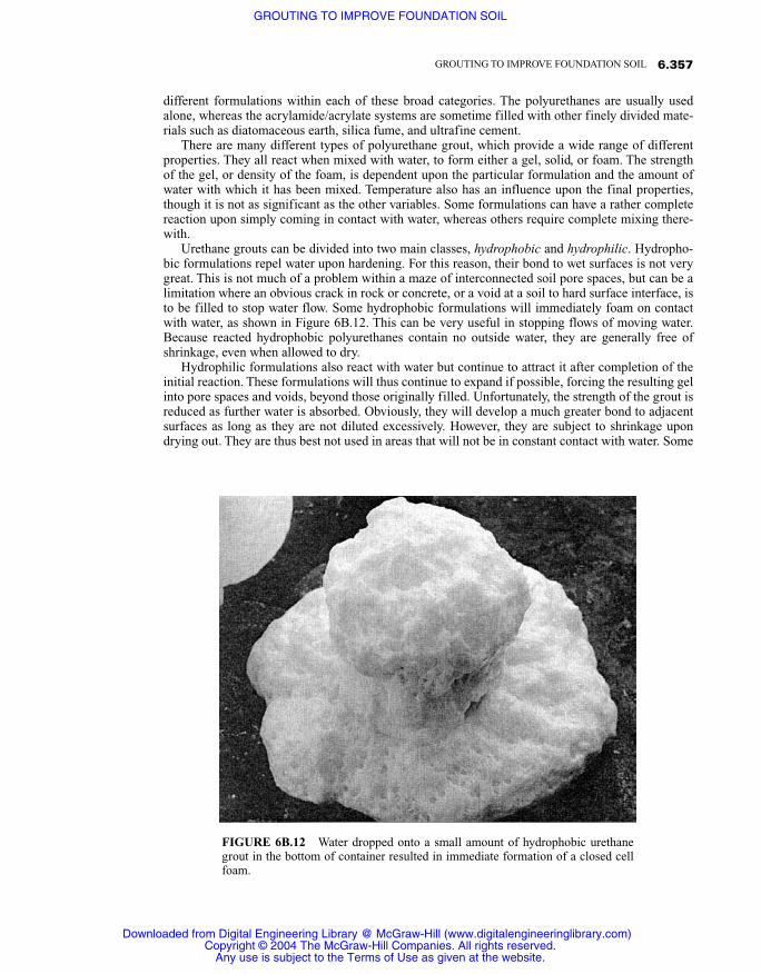
Urethane grouts can be divided into two main classes, hydrophobic and hydrophilic. Hydropho-bic formulations repel water upon hardening. For this reason, their bond to wet surfaces is not verygreat. This is not much of a problem within a maze of interconnected soil pore spaces, but can be alimitation where an obvious crack in rock or concrete, or a void at a soil to hard surface interface, isto be filled to stop water flow. Some hydrophobic formulations will immediately foam on contactwith water, as shown in Figure 6B.12. This can be very useful in stopping flows of moving water.Because reacted hydrophobic polyurethanes contain no outside water, they are generally free ofshrinkage, even when allowed to dry.
Hydrophilic formulations also react with water but continue to attract it after completion of theinitial reaction. These formulations will thus continue to expand if possible, forcing the resulting gelinto pore spaces and voids, beyond those originally filled. Unfortunately, the strength of the grout isreduced as further water is absorbed. Obviously, they will develop a much greater bond to adjacentsurfaces as long as they are not diluted excessively. However, they are subject to shrinkage upondrying out. They are thus best not used in areas that will not be in constant contact with water. Some
6.357GROUTING TO IMPROVE FOUNDATION SOIL
FIGURE 6B.12 Water dropped onto a small amount of hydrophobic urethanegrout in the bottom of container resulted in immediate formation of a closed cellfoam.
Downloaded from Digital Engineering Library @ McGraw-Hill (www.digitalengineeringlibrary.com)Copyright © 2004 The McGraw-Hill Companies. All rights reserved.
Any use is subject to the Terms of Use as given at the website.
GROUTING TO IMPROVE FOUNDATION SOIL

hydrophilic formulations require a minimum amount of water in order to react fully. This is typical-ly delivered into the grout, during injection, by means of a suitable dual pump proportioning system.
Urethane grouts are of two different categories chemically—those based on toluene diisocyanate(TDI) and diphenylmethane diisocyanate (MDI). The designations TDI and MDI are universallyused and well-established terms, and are often used alone for reference. The TDI based formula-tions, which usually are hydrophilic, will combine with all available water. The result will be a gel orflexible foam, the strength of which will depend upon the proportion of the combined water. Theystick tenaciously to wet surfaces and are very hard to remove or clean up should they be depositedupon an exposed surface. As illustrated in Figure 6B.13, spills of hydrophilic urethane grouts are ex-tremely difficult to clean up.
MDI formulations are generally hydrophobic, and while they require water to react, they willonly accommodate a specific amount thereof, and will displace any excess. They will thus often notdevelop a good bond to wet surfaces. They can be formulated so as to provide either flexible or rigidfoams, or solid masses.
Although the TDI liquids are generally safe to handle, the resulting vapor pressures in the air ex-ceed established threshold limits. Full protective precautions are thus required with their use. MDImixtures, on the other hand, have relatively lower vapor pressures, and are thus less hazardous. Witheither type, however, airborne droplets, such as might result from a leaking delivery line, are haz-ardous, although the cured gels are not. The safety aspects of working with urethane grouts are thor-oughly covered in “Recommendations for the Handling of Aromatic Isocyanates” (1976).
Mixed acrylamide/acrylate grouts are water-like solutions that provide very high penetrability.They are capable of exceptional control of the gelling time. Upon setting, the gel is very soft, en-abling it to be pumped out of the delivery system should it gel prematurely. While these factors arebenefits from the injection standpoint, they can be limitations for the injected grout. The resultinggel is quite weak, and subject to extrusion within any significant voids or defects in the soil. This
6.358 SOIL IMPROVEMENT AND STABILIZATION
FIGURE 6B.13 Hydrophilic urethane grout spills are extremely difficult to clean up.
Downloaded from Digital Engineering Library @ McGraw-Hill (www.digitalengineeringlibrary.com)Copyright © 2004 The McGraw-Hill Companies. All rights reserved.
Any use is subject to the Terms of Use as given at the website.
GROUTING TO IMPROVE FOUNDATION SOIL

limitation can be offset by inclusion of filler materials; however, the injectability goes down asfillers are added. This group of grouts finds its largest single use in the repair of leaking sewers andpipelines. Although the chemistry of the gelled grout is essentially the same, the origin of these ma-terials is different.
Acrylamide grouts were one of the earliest commercially available chemical solution grout sys-tems and were marketed by the American Cyanamid Company under the trade name AM-9. Theywere first marketed in 1955 and were extensively used for water control applications until 1978,when they were suddenly removed from the market. This was due to their manufacture being dis-continued following a toxicity problem in Japan, which resulted in a ban on their use in that country.Although the cured grouts are not toxic, the individual components are, so the unmixed componentsor any mixed solution that fails to gel, due, for instance, to dilution after injection, could present aserious risk.
Although not widely promoted, acrylamide grouts are still available in the United States, andcontinue to see extensive use for sewer maintenance. They are generally sold only to firms that areproperly equipped and have personnel who are especially trained in their safe use. The base materi-al is available in either a dry granular form or a fluid slurry. The slurry is considered less hazardousthan the dry form. The grout consists of separate solutions of the base material and the reactant sys-tem. These components are proportioned and impelled by separate synchronized pumps to the pointof injection where they are combined and stream mixed (Figure 6B.14). Both the gel time andstrength can be varied by adjusting either the strength of the starting solutions or the final mix ratio.
In order to enable variation of the final mix ratios, a variable proportioning pumping systemmust be used. The reactant portion of the grout is highly corrosive, so the mixers, pumps, and ap-purtenances on that side of the pumping system must be of plastic or stainless steel. Most of thework now being done with these grouts involves sophisticated pumping systems, requiring minimalhandling of either the unmixed ingredients or the resulting grout.
6.359GROUTING TO IMPROVE FOUNDATION SOIL
FIGURE 6B.14 Stream mixing of grout at the point of injection.
Downloaded from Digital Engineering Library @ McGraw-Hill (www.digitalengineeringlibrary.com)Copyright © 2004 The McGraw-Hill Companies. All rights reserved.
Any use is subject to the Terms of Use as given at the website.
GROUTING TO IMPROVE FOUNDATION SOIL

Acrylate grout was developed as an exact replacement for the acrylamide grout when AM9 wastaken off the market. It uses the same catalyst system and offers many of the advantages of the acry-lamide mixtures. The acrylate, which forms the base solution, however, is a prepolymer and is notneurotoxic as is the acrylamide monomer. The mixing and pumping equipment requirements are thesame for both grout types.
6B.3.2 Fluid Suspensions
Fluid suspension grouts were the first to ever be used, and they continue to be widely employed. Thelargest area of use for these grouts continues to be the filling of cracks and joints in rock, althoughtheir use has been extended greatly and includes controlled injection into soil. In the simplest form asuspension of ordinary portland cement and water is mixed. If all of the cement particles are to bethoroughly dispersed, high-shear mixing is required and the mixed grout must be continuously agi-tated to maintain the individual grains in suspension.
Cement grout mix design is expressed as the ratio of water to cementitious solids, either byweight or by volume. Volume measurements have been the most often used traditionally, as theywere very easy to make when using common bagged cement, which contains one cubic foot of drypowder per 94 pound bag. Where bulk cement is used, proportioning by weight is more convenient.In the United States, grout mixtures as thin as 10:1 by volume have been extensively used historical-ly. Many, including the writer, consider such thin grouts to be little more than dirty water, and exten-sive testing and research by the author and others (Houlsby, 1982; Weaver, 1991) have shown suchthin mixtures to provide little durability. Current thinking suggests that thicker mixtures (maximumW/C 3:1 by volume) are far more appropriate for most applications. In a well-documented discus-sion of appropriate water to cement ratios, Houlsby (1982) concluded that W/C 2:1 by volume hasbeen used on thousands of projects and is the optimal for general use.
Although unmodified common cement–water suspensions continue to be widely used, they suf-fer from settlement of the solids, resulting in accumulation of mix water at the top of unagitatedgrout. This is known as bleed and is an important factor to consider in any grout formulation. In thisregard, the amount of shear energy imparted during the mixing of the grout has an important bear-ing upon the resulting bleed. When cement and water come together, the cement grains tend toclump or floc together. To minimize the amount of bleed of a particular grout, high shear mixingwill break up the flocks and separate the individual cement grains. This factor was thoroughly dis-cussed by (Kravetz 1959). The essence of his conclusions, as reported by Houlsby (1990) are:
1. Cement grains, when mixed with water, tend to aggregate and form clumps. This slows the wet-ting process, as does air attached to the grains. The effect of high-speed shearing or laminating,plus the centrifugal effect, is to thoroughly break up the clumps and to separate air bubbles. As aresult, each individual grain is rapidly and thoroughly wetted and put into suspension.
2. During cement hydration, needlelike or springlike elements of hydrates form on the superficiallayer of each wetted grain of cement. In a high-speed mixer, the laminating effect and high-speedrotation keeps breaking these hydrates away from the grain of cement, thus exposing new areasto the water and consequently causing the formation of new elements. These hydrate elementsare of colloidal size, and as the amount of these elements in the mixture increases, the grout be-comes colloidal in character.
In reality, virtually no common cementitious suspension grout is truly colloidal, as even well-dispersed cement grains will settle in water unless special admixtures are used, as will be subse-quently discussed. High-shear mixing will greatly reduce and can in thick grouts nearly eliminatebleeding. In some places, but generally not the United States, a grout that exhibits little or no bleedis regarded as “stable.” Stable grouts are generally defined as those which exhibit a total of no morethan 5% bleed. European practice commonly calls for “stable” grouts, which typically include a fewpercent of bentonite to act as a suspension agent. Whereas bentonite inclusion will tend to lessen thecement grain settlement and resulting bleed, there are significant disadvantages to its use. Modern
6.360 SOIL IMPROVEMENT AND STABILIZATION
Downloaded from Digital Engineering Library @ McGraw-Hill (www.digitalengineeringlibrary.com)Copyright © 2004 The McGraw-Hill Companies. All rights reserved.
Any use is subject to the Terms of Use as given at the website.
GROUTING TO IMPROVE FOUNDATION SOIL

admixture technology offers a variety of different compounds that can minimize bleed without theundesirable aspects of admixed bentonite. These will be subsequently discussed in more detail.
6B.3.2.1 Soil Strengthening with Cementitious SuspensionsAs previously discussed, the grain size of ordinary portland cement grouts is too great to allow in-jection into all but the coarsest of sands and open gravels. Extending work of the Corps of Engi-neers, Technical Memorandum 3-408 (1956), and the work of a number of others, relative to the per-meation of soils with cement grouts, King and Bush (1961) concluded that grout would pass freelythrough a granular mass if the diameter of the particles in the grout was not greater than 6.7% thatof the material to be grouted. Their conclusions were the result of an extensive study, which consid-ered not only the largest sized particle in the grout, but also the variation and distribution of grainsizes, as well as consideration of the pore structure to be grouted.
The work was based on the premise that whereas two grains of cement wedged across a poreopening would form a stable bridge, and thus cause blockage, three grains would not be as stable.Although their work was based largely upon spherically shaped particles in the mass to be injected,it did consider the variation in pore structure that could be expected. They performed a number ofinjection tests in which a neat cement grout was injected into a specimen of natural, round-grainedaggregate. Although they included many aggregates in their test program, the finest was a sand,which was completely retained on a No. 8 sieve but passed 100% through a No.4 sieve. It should benoted that currently available common cements are ground somewhat finer than the cements evalu-ated by King and Bush.
In more recent times, there has been considerable discussion by a number of authors relative tothe filling of soil pore spaces with particulate grouts. The discussion has been concerned mainlywith mixtures containing ultrafine cement. Theoretical ratios of the grout particle size to the grainsize and thus porosity, of a given soil into which a particular cement grout can be injected are em-phasized. There has not been a great deal of agreement as to the appropriate ratios, and especiallywhether they should be based on the mean or maximum particle size of the cement. Although grainsize has been emphasized, it has been the author’s experience that grain size alone is only one im-portant aspect. The grain shape and surface condition, as well as the overall rheology of the grout,especially the thorough dispersion of the cement, are all significant. Also, of importance are thegrout pumping rate and sustained pressure level.
Suspension grouts are often injected under fairly high pressures, and pressure filtration, that is,loss of water from the solids due to the injection pressure, must not be allowed to occur. This is bestprevented by inclusion of a high-range water-reducing admixture in the mix, combined with high-shear mixing action, so as to maximize dispersion, and uniform wetting of the cement particles.Whereas in the filling of fissures or voids, the maximum grain size of the grout is not as importantas the overall grain size distribution, which will be discussed in more detail shortly, grain size is cru-cial when injection is into a granular deposit. This is because the particles can form a filter cakewhere they first enter the deposit, with the largest particles being restrained near the grout hole, fol-lowed by those which are progressively smaller, until permeation all but stops.
This is an important consideration, in that ultrafine cement suspension grouts, which are highlypenetrable and can form nearly colloidal mixtures, are seeing ever-increasing use for the solidifica-tion of sandy soils. Shimoda and Ohmori (1982) described the development of a new ultrafine ce-ment in Japan and reviewed laboratory research as well as two significant application case histories.Suspension grouts made with the then new cement were injected into fine to medium sands.
In more recent times, several manufacturers have introduced ultrafine cements, which are nowreadily available. Figure 6B.15 shows the grain size distribution for common portland as well asseveral ultrafine cements. It should noted that there are no standards regulating the actual grain sizedistribution for common cements. The curves shown in Figure 6B.15, for type I and III cement, arefor that produced in one particular batch at a given plant. ASTM C 150, “Standard Specification forPortland Cement,” specifies only the Blane fineness, which is a measure of the specific surface areaof all of the grains in a given volume of cement. Type III portland cement is required to be finer thantype I or II; however, the maximum grain size or grain size distribution, are not specified.
6.361GROUTING TO IMPROVE FOUNDATION SOIL
Downloaded from Digital Engineering Library @ McGraw-Hill (www.digitalengineeringlibrary.com)Copyright © 2004 The McGraw-Hill Companies. All rights reserved.
Any use is subject to the Terms of Use as given at the website.
GROUTING TO IMPROVE FOUNDATION SOIL

There are two main types of ultrafine cement: those based on slag and those based on portlandcement. Although the two are comparable in many respects, there is a fundamental difference in thespan of hydration and the resulting setting time. Because of the very high specific surface of ultra-fine cements of portland cement origin, hydration activity is high, resulting in rapid setting andstrength gain. For this reason, retarders such as citric acid are sometimes included. Portland ce-ment–citric acid combinations are extremely sensitive to temperature changes, so the proportions ofthe additive must be matched to the temperature of both the working environment and the mediumbeing injected. Problems with flash setting and difficulties with both setting time and rate ofstrength gain have been reported.
Cements based on slag, however, tend to set and gain strength much slower than their portlandcement cousins. Thus, retardation is seldom a problem, but accelerating admixtures may be requiredin some instances. Well-established accelerators are available and their behavior is quite predictable,so setting times are not much of a problem with the slag ultrafine cements.
These factors were well illustrated during a demonstration, which was part of the 21st AnnualShort Course on Fundamentals of Grouting, held in Denver, Colorado, September 12 to 17, 1999.Therein, vertical, transparent tubes, eight inches in diameter and five feet high, were filled withsand (Figure 6B.16). The sand was of quartz origin and was graded such that 100% passed a number
6.362 SOIL IMPROVEMENT AND STABILIZATION
FIGURE 6B.15 Particle size distribution of several cements used in fluid suspension grouts.
Downloaded from Digital Engineering Library @ McGraw-Hill (www.digitalengineeringlibrary.com)Copyright © 2004 The McGraw-Hill Companies. All rights reserved.
Any use is subject to the Terms of Use as given at the website.
GROUTING TO IMPROVE FOUNDATION SOIL

30 mesh sieve and 40% passed a number 40 sieve. It was carefully poured into the tubes such that alltubes were filled equally and had equal density.
Five different grout mixtures were injected into the sand, from the bottom of the columns. Theinjection was made at a pressure of 10 psi, which was maintained for twenty minutes on each col-umn. The degree of penetration of the various grouts was noted. All of the grout mixes had an iden-tical water to cement ratio of one. Mixture content and penetration rates for the various grouts areshown in Table 6B.4. Interestingly, the greatest degree of penetrability was not achieved with thefinest cement. This is consistent with real-world experience on many projects where ultrafine ce-ment grout has been injected into sandy soil. Obviously, there remains much to be learned aboutthese cements, and certainly, particle shape and surface characteristics are major contributors to thepenetrability of grouts in which they are used.
The thickest grout that can be readily mixed with the mixers commonly used in grouting is onthe order of 0.5:1 by volume. Lower W/C ratio grouts result in a mixture with pastelike consistency,generally referred to as a slurry. Slurry consistency grouts are sometimes used for filling smallvoids (0.3 to 3 inch) as well as for filling of controlled fractures in soil. They have also seen some
6.363GROUTING TO IMPROVE FOUNDATION SOIL
FIGURE 6B.16 Sand-filled columns used to evaluate cementgrout penetrability.
Downloaded from Digital Engineering Library @ McGraw-Hill (www.digitalengineeringlibrary.com)Copyright © 2004 The McGraw-Hill Companies. All rights reserved.
Any use is subject to the Terms of Use as given at the website.
GROUTING TO IMPROVE FOUNDATION SOIL

use in filling of large voids, such as abandoned mines (although this is inappropriate in the writer’sopinion). Slurries are generally too thick to be mixed in commonly available high-shear mixers.They are thus most often prepared in horizontal-shaft paddle mixers, such as those commonly usedto mix plaster and mortar, and thus are often particularly sensitive to bleed.
6B.3.3 Mortarlike Low-Mobility Grout
Very stiff mortarlike grouts were first developed in the United States in the mid 1950s. The originaluse of these very low mobility grouts was for the then developing technology of compaction grout-ing. With the advent of the modern concrete pump in the 1960s, it became practical to pump andplace under pressure typical concrete and mortar mixes. In recent times, admixture technology hasprovided the ability to alter conventional concrete and mortar mixtures, creating a wide range ofspecial properties. Of these, greatly increased plasticity, cohesion, and resistance to bleed are mostgermane to grouting.
Although many consider all mortarlike grouts to be equal, subject only to the slump, as deter-mined by ASTM C 143, such thinking is erroneous. As an example, the low-mobility grouts usedfor compaction grouting must exhibit high internal friction in order to provide placement controland prevent hydraulic fracturing of the soil into which they are being injected. Conversely, conven-tional concrete and mortar mixtures ideally possess relatively low internal friction, in order to pro-vide maximum workability. Stiff mortarlike grouts of the same slump are not necessarily equal inmobility when under pressure, either in the delivery system or in the ground. Whereas slump by it-self may be a sufficiently accurate measure for conventional concrete or mortar, and whereas suchmixes are quite satisfactory for fill grouting of large voids, the mix requirements for compactiongrouting are much more demanding, as will be discussed subsequently.
6B.4 GROUT RHEOLOGY
Simply stated, rheology is the study of the deformation and flow of materials. Perhaps more ger-mane to grouting, the American Concrete Institute, in their publication ACI 116 Cement and Con-crete Terminology (1990), defines rheology as “The science dealing with flow of materials, includ-ing studies of deformation of hardened concrete, the handling and placing of freshly mixedconcrete, and the behavior of slurries, pastes, and the like.” Satisfactory rheological properties of agrout in both the as-mixed as well as in the hardened state are fundamental to successful completionof any grouting project. The mixed grout must provide appropriate properties to enable proper injec-tion and travel within the particular formation to be improved. Obviously, the durability and long-term performance of the hardened grout is fundamental to achieving the intended performance. Theflow properties of grout materials vary widely, and a basic understanding of both fluid and plasticflow is requisite to either the study or understanding of grout flow.
Many grouts are subject to thixotropy, which is the performance of a material as an immobilepaste or gel when at rest, but as a fluid when energy is exerted on it. A common example of
6.364 SOIL IMPROVEMENT AND STABILIZATION
TABLE 6B.4 Penetration of various ultrafine cement grouts into experimental sand columns.
Grout mix/cement type Penetration from base (inches)
Type I Portland 4Type I Portland + 1% naphthalene superplasticizer 8Portland based ultrafine 9Slag based ultrafine 60 (flow from top in 7 minutes)Portland–pumice based ultrafine 57
Downloaded from Digital Engineering Library @ McGraw-Hill (www.digitalengineeringlibrary.com)Copyright © 2004 The McGraw-Hill Companies. All rights reserved.
Any use is subject to the Terms of Use as given at the website.
GROUTING TO IMPROVE FOUNDATION SOIL

thixotropic behavior is the pouring of catsup from a bottle. The catsup has a high resistance to flowout of the bottle at first attempt, but upon rapid shaking, flows readily. Many grouts are thixotropicin that they require a positive pressure of some magnitude to initiate movement within the deliverysystem, but flow freely at lower sustained pressure, once movement is initiated. This factor is impor-tant in considering allowable injection pressure for a given application, and an adequate initial pres-sure level to start flow must be provided. The flow behavior of fluids is a complex science. Here,only those properties that are fundamental to a basic understanding of grouting will be explained inas simple a manner as possible. Those who might desire a more technical explanation are referred toTattersall and Banfill (1983) and Mehta and Monteiro (1993).
Fluid and paste flow are described as either Newtonian or Binghamian. In Newtonian flow, theshear stress, which is the force required to move the fluid, is essentially constant, regardless of therate of movement, which is technically referred to as the shear strain. Water is an example of a New-tonian fluid. Bingham fluids, on the other hand, possess some thixotropy, and require a measurableforce (shear stress) to start movement. The magnitude of that force is usually referred to as the Bing-ham Yield Value, and sometimes, in reference to grout, the cohesion. With such grouts, the shearstress typically increases as the rate of shear (shear strain) increases. Typical stress–strain curves forboth Newtonian and Bingham flow are shown in Figure 6B.17. The slope of the Bingham curve in-dicates viscosity, which property will be dealt with in more detail later. Whereas some chemical so-lution grouts perform as Newtonian fluids, most fluid suspension and other grouts exhibit Bing-hamian behavior.
Behavior of non-Newtonian grouts, is not always as simple as indicated by the straight line rela-tionship of the applied shear stress and the shear rate or strain, as shown on Figure 6B.17. Althoughthe relationship of shear stress to shear rate can remain constant, as shown, it can also vary either upor down, depending upon the tendency of the material to thicken or thin with an increase in theshear rate. Figure 6B.18 demonstrates an instance of shear thickening where resistance to flow(pressure) increases with an increase in shear or flow rate. Some grouts will behave quite different-ly, wherein their resistance to flow will decrease as the shear or flow rate increases (shear thinning),as shown in Figure 6B.19.
6.365GROUTING TO IMPROVE FOUNDATION SOIL
FIGURE 6B.17 Newtonian and Binghamian flow indicating Bing-ham yield stress (cohesion).
Downloaded from Digital Engineering Library @ McGraw-Hill (www.digitalengineeringlibrary.com)Copyright © 2004 The McGraw-Hill Companies. All rights reserved.
Any use is subject to the Terms of Use as given at the website.
GROUTING TO IMPROVE FOUNDATION SOIL

6.366 SOIL IMPROVEMENT AND STABILIZATION
FIGURE 6B.18 Shear thickening.
FIGURE 6B.19 Shear thinning.
Shear Rate
Shear Rate
She
ar S
tres
sS
hear
Str
ess
Yie
ld S
tres
s
(Coh
esio
n)
Downloaded from Digital Engineering Library @ McGraw-Hill (www.digitalengineeringlibrary.com)Copyright © 2004 The McGraw-Hill Companies. All rights reserved.
Any use is subject to the Terms of Use as given at the website.
GROUTING TO IMPROVE FOUNDATION SOIL

Although incorrect, all too frequently only one or a few of the rheological properties pertainingto a particular grout mixture are used to describe the performance of that grout. One of the most fre-quent errors, is using the viscosity alone to define the injectability, when in fact knowing the viscos-ity is of little value unless other important properties such as surface tension and the resultingwetability are known. Grout rheology is very complex, and one must consider many important prop-erties. The writer suggests that the use of all-inclusive, simple terms to describe the properties of agrout are of more practical value, and recommends the descriptive terms mobility, for relativelythick grouts, and penetrability, for more fluid grouts, that are intended to fully permeate soil or rock.Each of these terms include many rheological influences and effects that must be evaluated in totalin order to rationally evaluate the propriety of that grout for a particular application.
6B.4.1 Mobility
Mobility denotes the ability of a grout material to travel through the delivery system and into the de-sired voids or intended deposition area within the geological formation being grouted. Of, equal im-portance is the ability to limit travel, so as to not flow beyond the zone of desired deposition. Thus,for proper performance, the grout should be of sufficient mobility to penetrate and fill the desiredgeotechnical defects, but it must be sufficiently limited so as to not flow beyond the desired injec-tion zone. When injection is made into soils, the mobility will also affect the manner in which thegrout behaves during injection.
When grout is placed in soil under pressure, it acts in one of three ways:
1. As a penetrant filling pore space, if the pumping rate is equal to or less than the rate at which thepore structure will accept the grout
2. As a fluid causing hydraulic fracturing of the formation if the pumping rate exceeds the perme-ation rate, or if the grout consistency does not allow it to permeate
3. As an expanding mass pushed by fluid-like pressure at the source of injection, so as to compressor compact the soil (Warner et al., 1992)
A common misconception is that a thick grout is always of low mobility, whereas a thin grout isalways highly mobile. Depending upon the individual mix constituents, thin grouts can be of rela-tively low mobility, whereas even very thick low slump grouts can be highly mobile and behave inthe soil as fluids. An example of the former would be fluid suspension grouts that contain blockingagents such as sawdust, mill feed, etc. (Technical Memorandum 646, 1957). Prior to development ofthe ability to pump low-mobility plastic consistency grouts, such low viscosity fluid grout mixtures,designed to restrict grout travel, were quite common.
Even very thick or essentially no-slump grout mixtures can be of sufficiently high mobility as toact like a fluid when injected into soil. Such behavior would typically be expected of grouts contain-ing clay components or admixtures such as some concrete pumping aids. When a grout injected intosoil behaves as a fluid, causing hydraulic fracturing, control of the grout placement is lost, and neg-ative occurrences are likely. This subject will be much more extensively discussed subsequently inrelation to compaction grouting.
In 1980, the American Society of Civil Engineers published the “Preliminary Glossary of TermsRelating to Grouting,” wherein they defined compaction grout as:
COMPACTION GROUT—Grout injected with less than 1 in (25 mm) slump. Normally asoil–cement with sufficient silt sizes to provide plasticity together with sufficient sand sizesto develop internal friction. The grout generally does not enter soil pores but remains in a ho-mogeneous mass that gives controlled displacement to compact loose soils, gives controlleddisplacement for lifting of structures, or both.”
Although, a standard test for “slump” was not defined by ASCE, many grouters have assumed that thewell-established slump cone used in ASTM C 143, (see Figure 6B.20), which is the most common
6.367GROUTING TO IMPROVE FOUNDATION SOIL
Downloaded from Digital Engineering Library @ McGraw-Hill (www.digitalengineeringlibrary.com)Copyright © 2004 The McGraw-Hill Companies. All rights reserved.
Any use is subject to the Terms of Use as given at the website.
GROUTING TO IMPROVE FOUNDATION SOIL

slump test, was intended. Many have ignored the inclusion of “sand sized” and “internal friction” inthe definition, and defined any grout with a low slump using the C 143 slump cone to be appropriate.
Notwithstanding the definition by ASCE, or the interpretation by grouters, the slump of a groutalone, is not a valid measurement of its rheological properties or appropriateness for compactiongrouting, or, for that matter, any grout application. The test was originally developed for appraisingthe workability of concrete that includes only clean sands and large aggregate. Even for use withthat material, for which the test was developed, ASTM states in their document, ASTM SpecialTechnical Publication 169B (1978),
Slump Test—The slump test . . . is the most commonly used method of measuring consisten-cy or wetness of concrete. It is not suitable for very wet or very dry concrete. It does notmeasure all factors contributing to workability, nor is it always representative of the place-ability of the concrete.
A mixture with a slump of only one inch is certainly “very dry,” and is a mixture that, according toASTM, the slump test is “not suitable” for. Typical low-mobility grouts, such as those used for com-paction grouting, contain silt-size particles, which tends to make them sticky. It is nearly impossibleto properly fill the slump cone with such material, let alone obtain repeatable results. Unless one isdealing with concrete that is not “very wet or very dry”, the slump test should not be used, and it mostcertainly is not appropriate for judging the rheology of most thick mortar-like grout mixtures.
6B.4.2 Penetrability
Penetrability defines the ability of a grout to permeate a porous mass, such as a sand or soil, or fillfractures or small voids. As previously discussed, viscosity alone is sometimes equated to the pene-trability of a given grout. In actual practice, however, penetrability of a grout into a given soil is de-
6.368 SOIL IMPROVEMENT AND STABILIZATION
FIGURE 6B.20 ASTM C 143 slump test in progress.
Downloaded from Digital Engineering Library @ McGraw-Hill (www.digitalengineeringlibrary.com)Copyright © 2004 The McGraw-Hill Companies. All rights reserved.
Any use is subject to the Terms of Use as given at the website.
GROUTING TO IMPROVE FOUNDATION SOIL

pendant upon a combination of viscosity and wetability. Within the viscosity ranges commonlyfound in solution grouts, wetability, which is defined by the contact angle of a drop of the fluid withthe receiving surface, is a far more important and significant property than viscosity. Wetability is afunction of the surface tension between the formation or granular surface and the solution at theirinterface.
This surface tension depends on the chemical composition of the grout being used and the chem-istry and physical conditions of the individual soils being treated. The affinity of the grout, whichresults from its wetability behavior in contact with the formation into or thorough which it is beingdriven, is thus of critical importance. This affinity, which includes the grout’s surface tension prop-erties, is fundamental to its penetrability. A simple example of the concept is the relative immobilityof a drop of water placed on a newly waxed surface, compared with the rapid dispersion of a drop ofthe same water placed on a similar but heavily oxidized surface.
An excellent example of this occurred during an experimental test program to develop the opti-mal grout for injection into several thousand feet of ⅜ inch OD tubing embedded within the em-bankment of a earth dam. The tubing had been installed in the embankment during the original con-struction, as part of an extensive instrumentation system. The test program was to include pumpingof grout through several thousand feet of tubing, to determine injection parameters that would be re-quired for the actual work. Although the original tubing was made of saran plastic, such materialwas no longer available, so a PVC plastic tubing of identical dimension was used.
As part of the evaluation, an eight foot length of tubing was secured to a slanted board, as shownin Figure 6B.21. Various trial grouts were then run through the tubing, with the flow times beingnoted. Because of a concern that the different tubing materials might react differently to the grout,an eight foot long piece of the original saran tubing was removed from a gallery in the dam. It wassecured to the slant board adjacent to the PVC tube, and fed with grout from a common funnel, asillustrated in Figure 6B.22. Interestingly, the grout flowed more easily in the PVC tubing, as can be
6.369GROUTING TO IMPROVE FOUNDATION SOIL
FIGURE 6B.21 Tubing attached to slant board for grout flow evaluation.
Downloaded from Digital Engineering Library @ McGraw-Hill (www.digitalengineeringlibrary.com)Copyright © 2004 The McGraw-Hill Companies. All rights reserved.
Any use is subject to the Terms of Use as given at the website.
GROUTING TO IMPROVE FOUNDATION SOIL

seen in Figure 6B.23, wherein the graduated cylinder on the right is filled much higher than that ofthe left, below the saran tubing.
The most promising grout mixes were then pumped through several thousand feet of thePVC tubing, Figure 6B.24. As a result of the slant board tests, a correction factor was developedfor the saran tubing, allowing an accurate calculation of the grout pressure that would be requiredto inject the saran tubing existing in the dam. As confirmed by these tests, the penetrabilityof a grout is not solely dependent upon its viscosity. Low-viscosity grouts can have poor penetra-bility, whereas highly viscous grouts can be very penetrable, in a given delivery system or forma-tion.
In the case of grouts that contain solids, such as fluid suspensions and slurries, the grain size ofthe solids also affects the grout’s ability to penetrate. Theoretical research and discussion abound,relative to the ratio of maximum grain size that can penetrate a given crack and/or joint width in thegrouting of rock. Although the subject is somewhat contentious, in rock grouting there is generalagreement that the minimum dimension of the defect must be at least three to five times that of themaximum grain size in the grout. Although the maximum grain size unquestionably affects the pen-etrability of an obvious defect, the author suggests that it is only one consideration, and perhaps notthe most important.
As an example, should a grout contain only a small percentage of the maximum size particles,and those particles were well distributed so they were not adjacent to or in near proximity of eachother, the maximum size would not be of great significance, as long as their dimension were lessthan that of the void being filled. Conversely, if the grout contained a larger proportion of the large-size particles and/or they were in near proximity of each other, the risk of blockage would be muchgreater, and thus the maximum size of the particles more significant. Regardless of the grain size, ofparticular importance in all cases is the amount of shear energy applied during the grout mixing. It
6.370 SOIL IMPROVEMENT AND STABILIZATION
FIGURE 6B.22 Both tubes are simultaneously filled through a common funnel.
Downloaded from Digital Engineering Library @ McGraw-Hill (www.digitalengineeringlibrary.com)Copyright © 2004 The McGraw-Hill Companies. All rights reserved.
Any use is subject to the Terms of Use as given at the website.
GROUTING TO IMPROVE FOUNDATION SOIL

6.371GROUTING TO IMPROVE FOUNDATION SOIL
FIGURE 6B.23 Cylinder on right is filling faster than that on the left.
FIGURE 6B.24 Test grouts were pumped through several thousand feet of coiled tubing tosimulate conditions actually existing in the dam.
Downloaded from Digital Engineering Library @ McGraw-Hill (www.digitalengineeringlibrary.com)Copyright © 2004 The McGraw-Hill Companies. All rights reserved.
Any use is subject to the Terms of Use as given at the website.
GROUTING TO IMPROVE FOUNDATION SOIL

has an important influence on the dispersion of the individual grains, and thus the penetrability ofthe resulting grout.
The shape of the particles and condition of their surface are also of immense importance. Rough,angular particles are far more likely to form blockages within a pore space or defect than are smoothround ones. Experience has repeatedly shown that cementitious grouts containing large amounts ofpozzolanic materials, such as fly ash or silica fume, are more penetrable than those containing onlycement. This is no doubt the result of the near spherical shape of most pozzolans. Round shapedgrains tend to roll past and over each other, rather than bind together as would rough angular shapes.
Although the terms mobility and penetrability are perhaps the most all-inclusive for describingthe rheological properties of a grout, there are other factors that must also be considered to assurethe proper selection and applicability of a grout mix.
6B.4.3 Cohesion
Lombardi (1985) reported on a simple field test to determine the “cohesion” of a grout. What Lom-bardi is actually evaluating is the Bingham Yield Value for the grout, albeit with a simple test. It in-volves dipping a 10 cm square, slightly roughened metal plate approximately of ⅛th inch thick (Fig-ure 6B.25) into the grout and measuring the weight of the grout that remains on the plate afterremoval.
6B.4.4 Bleed
When at rest, the individual particles of a fluid suspension grout will tend to settle out of the so-lution. This is referred to as bleed. To prevent bleeding of the grout prior to injection, it is usual-
6.372 SOIL IMPROVEMENT AND STABILIZATION
FIGURE 6B.25 Lombardi cohesion test.
Downloaded from Digital Engineering Library @ McGraw-Hill (www.digitalengineeringlibrary.com)Copyright © 2004 The McGraw-Hill Companies. All rights reserved.
Any use is subject to the Terms of Use as given at the website.
GROUTING TO IMPROVE FOUNDATION SOIL

ly continuously agitated after mixing. Whereas excessive bleed will not occur under proper agita-tion, it can occur when the grout is essentially at rest, either during or after injection. This is ofparticular significance where large quantities of grout have been injected into a single location orvoid, or where the injection rate is very slow. As bleed occurs, the solids will settle to the bottomof the void or defect being filled, and the top portion will be filled initially with water, and even-tually with air, leaving void space. The bleed potential of a grout can be greatly reduced by verythrough, high-shear mixing, as well as through thoughtful mix design, including the judicious useof admixtures.
6B.4.5 Setting Time
In many cases, control of the time required for a grout to set or harden can be crucial to properperformance. It is imperative that grout injected into a given hole has set or become immobileprior to the drilling of adjacent holes. Rapid setting times are usually desirable when injection isinto moving water, so the grout mass will set before it is washed away. Even where the water isnot moving, a rapid setting will minimize the opportunity for dilution of the grout. In many casesof soil strengthening or groutjacking, rapid strength development is required in order to limitdowntime of a facility. Conversely, where injection is to be made through a very long delivery sys-tem, or into large linear void spaces, extension of the setting time might be required, so as to pre-vent hardening of the grout within the delivery system or the initially filled portions of the void.Admixtures are commercially available that can either accelerate or delay the setting time of allcementitious grouts. In the case of chemical solution grouts, the setting time can often be con-trolled through judicious proportioning of the mix ingredients, or the use of set controlling com-ponents.
6B.4.6 Solubility
When mixing a solution grout, rapid dilution of all the components is beneficial and shortens boththe amount of time and energy required for mixing. If the grout is to be placed into a saturated for-mation or void, however, the ability of the mixed grout to easily dissolve is undesirable. Under suchplacement conditions, and especially where the water is moving, a grout of low solubility in water isdesirable. It is also important to assure that the particular grout to be used will not be adversely ef-fected by the chemistry of the formation or ground water into which it is to be injected. An examplewould be attack of the grout curtain under a tailings dam by retained acidic water.
Properties of grout in the hardened state are also often very important. Is the purpose of thegrouting short term, such as solidification of sandy soils to permit tunneling or excavation, or mustthe improvement be permanent? If strengthening of the soil is desired, the grout or the grouted massmust be of sufficient strength and/or stiffness. In many applications, the dimensional stability orshrinkage of the grout must be considered. Nearly all chemical solution grouts shrink when allowedto dry, as do most cementitious compositions.
Durability of the hardened grout, under the conditions that exist at the injection location, shouldalso be evaluated. In this regard, chemistry of both the soil and the ground water, to which the groutmight be exposed, should be appraised, as well as any unusual chemical exposures that might occurduring the lifetime of the installation. Exposure to unusual temperature variations must also be con-sidered, as the setting time of virtually all grouts is temperature dependent, as is the durability ofmany. Both the strength and durability of chemically grouted masses are dependent upon their mois-ture state. The ability to resist syneresis (the exudation of liquid from the grout) or extrusion of thegrout from its intended location is also of importance, especially when the purpose of the groutingis the blockage of high heads of retained water.
Most reacted water-control grouts will shrink upon drying. Some will swell upon being rewetted;however, there is often a substantial time lag for complete expansion, and often times it will not be
6.373GROUTING TO IMPROVE FOUNDATION SOIL
Downloaded from Digital Engineering Library @ McGraw-Hill (www.digitalengineeringlibrary.com)Copyright © 2004 The McGraw-Hill Companies. All rights reserved.
Any use is subject to the Terms of Use as given at the website.
GROUTING TO IMPROVE FOUNDATION SOIL

to the full volume that existed prior to drying. Although this is of little concern where the grout willalways be in contact with water, it is an important consideration in arid regions or other locationswhere drying might occur.
6B.5 TESTS FOR EVALUATION OF GROUTS
Simple field test methods to assure the quality and propriety of the grout are unquestionably one ofthe greatest needs in geotechnical grouting. Unfortunately, few simple tests exist for either very thinor very thick grouts. A number of tests do exist, however, for mid-range grout consistencies, whichare generally fluid suspensions.
6B.5.1 Flow Cones
Several different configurations of funnel devices have been proposed or used to evaluate the flowproperties of grout, two of which have become somewhat commonly used. The “flow cone,” Figure6B.26, originally developed in the early 1940s, has been used for many years by the U.S. ArmyCorps of Engineers under the designation CRD-C611, for both research and field quality assurance.In 1981, it was adopted by ASTM as part of their C939 “Standard Test Method for Flow of Grout forPreplaced Concrete Aggregate.” The Marsh funnel, Figure 6B.27, long used to evaluate the flowproperties of drilling fluids, is now also used for pourable grouts.
Flow evaluations are made by filling the funnels while holding a finger over the outlet. The fin-ger is then released, allowing the funnel to empty. The time is noted to the nearest second, providingthe number of seconds required for the cone to completely empty. This is known as the efflux time.The C939 cone is typically made of cast aluminum, whereas the Marsh funnel is usually made of
6.374 SOIL IMPROVEMENT AND STABILIZATION
FIGURE 6B.26 ASTM C939 Flow Cone.
Downloaded from Digital Engineering Library @ McGraw-Hill (www.digitalengineeringlibrary.com)Copyright © 2004 The McGraw-Hill Companies. All rights reserved.
Any use is subject to the Terms of Use as given at the website.
GROUTING TO IMPROVE FOUNDATION SOIL

plastic. Neither material can have wetability properties at all similar to the wide variety of geomate-rials into which a grout might be injected. They do, however, provide for easy confirmation of theuniformity of different batches of grout and are widely used in quality assurance testing.
6B.5.2 Specific Gravity
Another testing device that was originally developed for the evaluation of drilling fluids is theBaroid Mud Balance, Figure 6B.28. It is a simple and very rugged device for determining the densi-ty of drilling mud or grout. In application, the cup and beam are removed from the fulcrum, and thecup is dipped into the grout until it is completely filled. Any excess grout that has come in contactwith the beam or outside of the cup is removed. The beam and cup are then placed on the fulcrum,and the weight is slid along the beam until the bubble of an attached spirit level is centered. The den-sity is then read directly from a scale on the beam. The mud balance is a particularly useful devicefor quality assurance testing of cement–water suspensions, in that the water to cement ratio can beeasily and accurately determined.
6.375GROUTING TO IMPROVE FOUNDATION SOIL
FIGURE 6B.27 Marsh funnel.
Downloaded from Digital Engineering Library @ McGraw-Hill (www.digitalengineeringlibrary.com)Copyright © 2004 The McGraw-Hill Companies. All rights reserved.
Any use is subject to the Terms of Use as given at the website.
GROUTING TO IMPROVE FOUNDATION SOIL

6B.5.3 Evaluation of Bleed
Controlling the bleed of suspension grouts is also important, especially when slow pumping ratesare used or large voids are being filled. The bleed potential of a suspension grout can change quitemarkedly with changes of water to cement ratio, shear mixing energy, or changes in properties ofthe cement or other grout constituents. Bleed evaluation is easily accomplished by filling a transpar-ent tube or jar with the grout and observing the amount of clear water that collects on the top afterabout two hours. Where accurate determinations are desired, 1000 ml graduated cylinders, as shownin Figure 6B.29, can be used. These can be used in a manner similar to that provided in ASTM C940, “Standard Test Method for Expansion and Bleeding of Freshly Mixed Grouts for Preplaced-Aggregate Concrete in the Laboratory.” Whereas this procedure is useful for laboratory evaluations,the required settlement time often renders it impractical for the control of injection parameters inthe field.
6B.5.4 Pressure Filtration
Pressure filtration is essentially bleed forced by the pumping pressure imposed upon the grout. Itcan be evaluated for common cement grouts with a standard Gelman pressure filter. The 47 mm di-ameter test chamber shown in Figure 6B.30, fitted with a disposable glass fiber filter, works well on
6.376 SOIL IMPROVEMENT AND STABILIZATION
FIGURE 6B.28 Baroid mud balance used for evaluation of grout density.
Downloaded from Digital Engineering Library @ McGraw-Hill (www.digitalengineeringlibrary.com)Copyright © 2004 The McGraw-Hill Companies. All rights reserved.
Any use is subject to the Terms of Use as given at the website.
GROUTING TO IMPROVE FOUNDATION SOIL

6.377GROUTING TO IMPROVE FOUNDATION SOIL
FIGURE 6B.29 Evaluation of the bleedof two cementitious water suspensiongrouts with different water to cement ratios.
FIGURE 6B.30 Pressure filtration evaluationwith Gelman filter apparatus.
Downloaded from Digital Engineering Library @ McGraw-Hill (www.digitalengineeringlibrary.com)Copyright © 2004 The McGraw-Hill Companies. All rights reserved.
Any use is subject to the Terms of Use as given at the website.
GROUTING TO IMPROVE FOUNDATION SOIL

grouts based on common cements. Various applied pressures on the grout can easily be imposed bypressure regulation of bottled nitrogen gas, which is typically used.
6B.5.5 Slump
As previously discussed, standard slump tests are not appropriate for either very wet or very drymixtures, and certainly not for the rather sticky mixtures that are common in grouting. Except forthe rather rare instances of fill grouting, in which standard concrete or mortar is being injected, theslump test should be neither specified nor used. Where it is mentioned, however, the particularstandard should be provided. There are several different established slump tests that involve moldsof different sizes and configurations than the most common ASTM C 143 test, shown in Figure6B.20.
6B.5.6 Strength Tests
In most cases of soil grouting, grout strength is of little concern as long as it is at least that of thesoil. In fact, a mistake frequently made is specification of cementitious grout strength, based ontypical concrete or mortar standards. Specifying unnecessarily high strength for the grout is inmost cases of no benefit, can present difficulties for the contractor, and usually results in in-creased costs. In those cases where strength is of importance, either standard unconfined or triax-ial compression tests can be made. Specimens for grout are usually standard 2 by 4 inch cylindersor two inch cubes.
In the case of permeation grouted masses, it is not the strength of the grout that is of importance,but rather that of the resulting solidified soil mass. In such cases, any laboratory tests, to be mean-ingful, must involve saturation of the proposed grout into a confined mass of the particular soil.ASTM Standard D 4220, “Test Method for Laboratory Preparation of Chemically Grouted SoilSpecimens for Obtaining Design Strength Parameters,” is applicable for the preparation of suchspecimens. Because virtually all laboratory tests rely on remolded specimens, the indicatedstrengths may not compare closely to that of the in-place grouted soils, however the indicatedstrength should give a good idea of the strength levels that can be reasonably expected.
In order to verify field strength performance, specimens should be carved from the actualgrouted mass for evaluation. This will require excavating to the grouted zone for access. Coredrills can be used to obtain specimens of many masses of cement grouted soil and those soils thathave been solidified with higher strength chemical solution grout, provided the soil zone wherethe core is taken has been completely permeated and essentially all of the pore space filled. Grout-ed soils are usually of much lower strength than grouted rock, and some erosion and disturbanceof the core surface often results from the drilling operations. It is sometimes useful to procure acore of greater diameter than is required for the test and then carve it down to the required size.Be aware, however, that very often it is not possible to obtain a proper core specimen of groutedsoil. This is especially so where weaker grouts are used or the soil pore space is not completelyfilled. The strength of many grouts and virtually all chemical solution grouted masses are signif-icantly affected by their moisture condition. It is thus crucial to preserve the moisture condition ofthe specimen as obtained, and often precludes the use of core drilling for specimens that are abovethe water table.
Because chemically grouted masses are subject to significant creep, and the fundamentalstrength is often significantly less than that indicated by the rather rapid loading of the ASTM D4219 test, which was previously discussed, variable strain, constant stress compression tests, such asshown in Figure 6B.31, are preferable. The simple device illustrated operates on compressed air, andthe imposed load level is easily controlled by varying the air pressure with a regulator, such asshown on the right, bottom, of the figure. Such simple equipment can easily be taken to the job siteand tests run immediately upon retrieval of the specimens.
6.378 SOIL IMPROVEMENT AND STABILIZATION
Downloaded from Digital Engineering Library @ McGraw-Hill (www.digitalengineeringlibrary.com)Copyright © 2004 The McGraw-Hill Companies. All rights reserved.
Any use is subject to the Terms of Use as given at the website.
GROUTING TO IMPROVE FOUNDATION SOIL

6B.6 TYPES OF GROUTING
Classification of the many different types of soil grouting is a difficult task at best. This is due to thewide variety of different grout materials and end uses, as well as the many different injection meth-ods and procedures. Additionally, much confusion results from the promotion of a variety of “pro-prietary” terminology by grouters, in an attempt to make their activities appear to be something spe-cial. Perhaps the best classification for different methods of soil grouting was presented byXanthakos, Abramson, and Bruce (1994). Therein, four different categories of soil grouting areidentified:
1. Hydrofracture (or claquage)
2. Compaction
3. Permeation
4. Jet (or replacement)
6B.6.1 Fracture/Claquage Grouting
Fracture grouting involves the intentional hydrofracture of the soil by a fluid suspension or slurrygrout, with the intent of producing a network of interconnected grout-filled lenses to act as rein-
6.379GROUTING TO IMPROVE FOUNDATION SOIL
FIGURE 6B.31 Constant stress testing apparatus with testin progress.
Downloaded from Digital Engineering Library @ McGraw-Hill (www.digitalengineeringlibrary.com)Copyright © 2004 The McGraw-Hill Companies. All rights reserved.
Any use is subject to the Terms of Use as given at the website.
GROUTING TO IMPROVE FOUNDATION SOIL
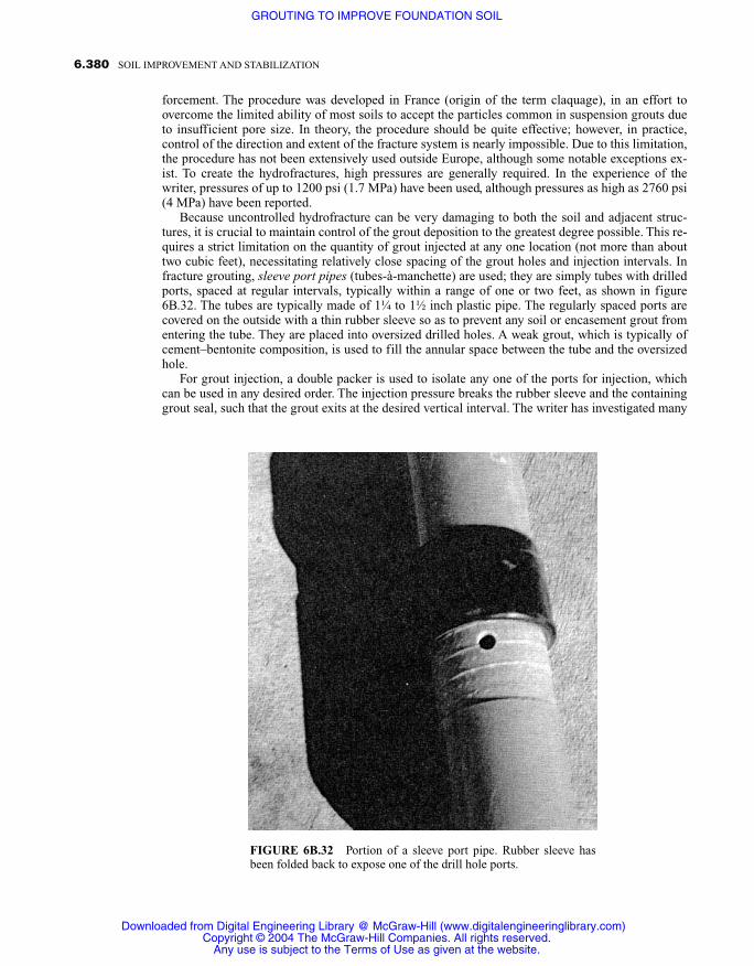
forcement. The procedure was developed in France (origin of the term claquage), in an effort toovercome the limited ability of most soils to accept the particles common in suspension grouts dueto insufficient pore size. In theory, the procedure should be quite effective; however, in practice,control of the direction and extent of the fracture system is nearly impossible. Due to this limitation,the procedure has not been extensively used outside Europe, although some notable exceptions ex-ist. To create the hydrofractures, high pressures are generally required. In the experience of thewriter, pressures of up to 1200 psi (1.7 MPa) have been used, although pressures as high as 2760 psi(4 MPa) have been reported.
Because uncontrolled hydrofracture can be very damaging to both the soil and adjacent struc-tures, it is crucial to maintain control of the grout deposition to the greatest degree possible. This re-quires a strict limitation on the quantity of grout injected at any one location (not more than abouttwo cubic feet), necessitating relatively close spacing of the grout holes and injection intervals. Infracture grouting, sleeve port pipes (tubes-à-manchette) are used; they are simply tubes with drilledports, spaced at regular intervals, typically within a range of one or two feet, as shown in figure6B.32. The tubes are typically made of 1¼ to 1½ inch plastic pipe. The regularly spaced ports arecovered on the outside with a thin rubber sleeve so as to prevent any soil or encasement grout fromentering the tube. They are placed into oversized drilled holes. A weak grout, which is typically ofcement–bentonite composition, is used to fill the annular space between the tube and the oversizedhole.
For grout injection, a double packer is used to isolate any one of the ports for injection, whichcan be used in any desired order. The injection pressure breaks the rubber sleeve and the containinggrout seal, such that the grout exits at the desired vertical interval. The writer has investigated many
6.380 SOIL IMPROVEMENT AND STABILIZATION
FIGURE 6B.32 Portion of a sleeve port pipe. Rubber sleeve hasbeen folded back to expose one of the drill hole ports.
Downloaded from Digital Engineering Library @ McGraw-Hill (www.digitalengineeringlibrary.com)Copyright © 2004 The McGraw-Hill Companies. All rights reserved.
Any use is subject to the Terms of Use as given at the website.
GROUTING TO IMPROVE FOUNDATION SOIL

instances of damage resulting from uncontrolled hydrofracture grouting, and is of the strong opin-ion that where performed, strict limitations of grout quantities, combined with meticulous observa-tion and control of the grout pressure and other injection parameters, are essential. Fracture groutingcan be performed in virtually any soil and to any depth.
There are other grouting methods, which are usually both faster and more economical thanclosely controlled fracture grouting, for the strengthening of most soils. A clear exception wherefracture grouting is applicable however, involves the pressure injection of hydrated lime slurry tostabilize the moisture in, and reduce the expansive potential of, clay soil. Because the chemical re-action requires contact of the lime with the soil, closely spaced fractures are needed. This type of in-jection is usually done on a fairly large-scale basis by contractors who specialize in it. The equip-ment tends to be massive, possessing several probes with perforated pointed tips, which are pushedinto the soil simultaneously, with either continuous or discrete injections of the lime slurry (Figures6B.33 and 6B.34). As can be observed, the process can be quite messy, and avoiding lime depositionon either the equipment or surrounding surfaces is nearly impossible. Although the slurry has a dis-tinctive white color, and is quite alkaline, with a pH of about 12, it presents no serious health or en-vironmental risks, and is fairly rapidly diluted by rainfall or washing, and then absorbed into thesurface soil. The high alkalinity, however, can cause burns on human flesh if allowed to remain incontact for an extended time. Spills should therefore be promptly washed off the skin.
The depth of treatment depends upon the expansive potential of the subject soil. It is usually onthe order of 5 to 20 feet, but applications as great as 40 feet, have been reported. The slurry consists
6.381GROUTING TO IMPROVE FOUNDATION SOIL
FIGURE 6B.33 Small-scale lime injection
Downloaded from Digital Engineering Library @ McGraw-Hill (www.digitalengineeringlibrary.com)Copyright © 2004 The McGraw-Hill Companies. All rights reserved.
Any use is subject to the Terms of Use as given at the website.
GROUTING TO IMPROVE FOUNDATION SOIL

simply of water mixed with about 25 to 30% by weight of dry hydrated lime. A surfactant wettingagent is often included to improve penetrability of the slurry. It is typically injected at pressureswithin a range of 50 to 200 psi. Injection is continued until either refusal at the maximum pressureor surface leakage occurs, or the predetermined amount of slurry, which is typically about 10 gal-lons per vertical foot of hole, has been placed. Because the injection slurry consists primarily of wa-ter, which can be absorbed into the clay, some accelerated expansion can take place, immediately af-ter injection, unless the initial soils moisture content was near its maximum level. This expansiontends to stabilize shortly after the injection, however, usually within a period of two or three weeks.
Lime injection has been subject to considerable promotion by those who perform the work aswell as the National Lime Association, a trade organization for manufacturers of commercial quick-lime and hydrated lime. The association has made available a publication by Boynton and Blacklock(1986) that includes a comprehensive bibliography of 51 references.
In 1967, the writer was involved in the remediation of damage to the slab on grade floor of threelarge dormitories at the Hollygrove Orphanage, in Hollywood, California. An investigation dis-closed that the floor slab had experienced upward movement of as much as 1.5 inches. An addition-al heave of 2.75 inches was predicted. The cause of the upheaval was determined to be a layer ofhighly expansive clay, underlying the floor at a depth of two to seven feet. Because funding was re-stricted and moving the occupants out of the structure was not possible, lime injection was adoptedas the most reasonable remedial method, although it was considered somewhat experimental at thetime.
As previously mentioned, lime injection is inherently messy, so great care was taken to performthe work with as little damage to the structure as possible. Injection holes were located on a threefoot grid, normal to the module of the existing 12 inch square floor covering tiles. The work was ac-complished with only minor disturbance and the structures were occupied throughout the work.Limitation of floor covering replacement to only those tiles at the hole locations, and waxing of the
6.382 SOIL IMPROVEMENT AND STABILIZATION
FIGURE 6B.34 Large-scale lime injection.
Downloaded from Digital Engineering Library @ McGraw-Hill (www.digitalengineeringlibrary.com)Copyright © 2004 The McGraw-Hill Companies. All rights reserved.
Any use is subject to the Terms of Use as given at the website.
GROUTING TO IMPROVE FOUNDATION SOIL

entire floor upon completion of the work, resulted in a large cost savings to the owner. The replace-ment tiles were of bright colors to provide an accent, which actually improved the esthetics of theoriginal construction.
The slurry consisted of high-calcium hydrated lime mixed with water, at the rate of about 4.2pounds of lime per gallon of water, to make a nearly 50% mixture by weight. The injection rate washeld to a relatively low value of about 0.6 cubic feet per minute, in order to minimize leakage. Injec-tion pressure varied between 50 and 250 psi. Reading from a report prepared after completion of thework:
The slurry was injected from the top down through special injection needles made especiallyfor this work. The needle was driven downward from the surface until the clay layer was“felt,” after which a metered quantity of 0.25 cubic feet (7 L) of slurry or 7.5 pounds (3.4 kg)of lime was injected. The needle was then continued downward in 6 inch increments, the me-tered amount of slurry injected at each, until the bottom of the clay layer was “felt” or minus7 feet was reached. In some cases it was not possible to inject the full measure of slurry dueto uplift of the structure walls or floor.
Several elevation surveys had been taken prior to the work. Others were taken immediately fol-lowing completion and at 30, 90, 180, and 360 days thereafter. Immediately following the injection,an additional upward movement of about 0.25 inch (6 mm) was recorded. No further movement wasnoted thereafter, and, in fact, after one year a portion of the original 0.25 inch (6 mm) of heave wasrecovered.
6B.6.2 Compaction Grouting
Compaction grouting involves injection of very stiff, mortar-like, low-mobility grout at high pres-sure into discrete zones of soil. Because of the low mobility of the grout, much higher pressures areused than in traditional grout injection. It is not unusual to experience pressures of several hundredpsi when injection is made at depths of only five or ten feet. Properly placed, the grout remains in ahomogeneous, expanding mass, which displaces and thus compacts the adjacent soil, increasing itsdensity. Fundamental to the success of the procedure is deposition of the grout in such a manner thatit remains in a globular mass at the injection location, with a distinct grout–soil interface. In deed,one of the primary advantages of the technique is that absolute control of the grout deposition loca-tion is possible.
The work is virtually always done in stages; that is, only a few feet of the grout hole are injectedat any one time. The staging can be from the top down (downstage) or from the bottom up (upstage).The upstage method is the fastest and most economical, and thus, the most frequently used, espe-cially for deep injection. For shallow injection (less than about 15 feet), working downstage has thedistinct advantage, in that each injected stage provides additional restraint and containment forthose that follow. Thus, higher pressures, which enable a greater quantity of grout to be injected, andthus greater densification, can be used in the deeper stages, after the overlying soils have beenstrengthened. Whereas upstage injection is nearly always accomplished in one continuous opera-tion, when working downstage, each stage is allowed to harden before the next one is drilled andgrouted.
Grouting upstage involves:
1. Drilling a hole to the bottom of the zone to the grouted.
2. Placing casing to within a few feet of the bottom of the hole. The casing should be a snug fit andmay require pushing or driving into place. Sometimes it is driven entirely, the predrilling beingeliminated.
3. Injection of the grout is continued until essential “refusal” is reached. Refusal is usually consid-ered as: a) a slight movement of the overlying ground surface or improvements, b) injection of a
6.383GROUTING TO IMPROVE FOUNDATION SOIL
Downloaded from Digital Engineering Library @ McGraw-Hill (www.digitalengineeringlibrary.com)Copyright © 2004 The McGraw-Hill Companies. All rights reserved.
Any use is subject to the Terms of Use as given at the website.
GROUTING TO IMPROVE FOUNDATION SOIL
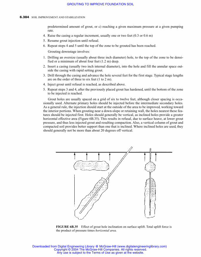
predetermined amount of grout, or c) reaching a given maximum pressure at a given pumpingrate.
4. Raise the casing a regular increment, usually one or two feet (0.3 or 0.6 m)
5. Resume grout injection until refusal.
6. Repeat steps 4 and 5 until the top of the zone to be grouted has been reached.
Grouting downstage involves:
1. Drilling an oversize (usually about three inch diameter) hole, to the top of the zone to be densi-fied or a minimum of about four feet (1.2 m) deep.
2. Insert a casing (usually two inch internal diameter), into the hole and fill the annular space out-side the casing with rapid setting grout.
3. Drill through the casing and advance the hole several feet for the first stage. Typical stage lengthsare on the order of three to six feet (1 to 2 m).
4. Inject grout until refusal is reached, as described above.
5. Repeat steps 3 and 4, after the previously placed grout has hardened, until the bottom of the zoneto be injected is reached.
Grout holes are usually spaced on a grid of six to twelve feet, although closer spacing is occa-sionally used. Alternate primary holes should be injected before the intermediate secondary holes.As a general rule, the injection should start at the outside of the area to be improved, working towardthe interior portions. When grouting near a down-slope or retaining wall, the holes nearest these fea-tures should be injected first. Holes should generally be vertical, as inclined holes provide a greaterhorizontal effective area (Figure 6B.35). This results in refusal, due to surface heave, at lower groutpressure, and thus less injected grout and resulting compaction. Also, a vertical column of grout andcompacted soil provides better support than one that is inclined. Where inclined holes are used, theyshould generally not be more than about 20 degrees off vertical.
6.384 SOIL IMPROVEMENT AND STABILIZATION
FIGURE 6B.35 Effect of grout hole inclination on surface uplift. Total uplift force isthe product of pressure times horizontal area.
Downloaded from Digital Engineering Library @ McGraw-Hill (www.digitalengineeringlibrary.com)Copyright © 2004 The McGraw-Hill Companies. All rights reserved.
Any use is subject to the Terms of Use as given at the website.
GROUTING TO IMPROVE FOUNDATION SOIL

Compaction grout casing is typically two to four inch (5 to 10 cm) ID steel tubing. Some con-tractors use proprietary casing, while others use either standard flush wall drill casing or iron pipe.The outside surface of the casing should always be of a uniform diameter, which usually means aflush wall threaded coupling. When working upstage, the casing, and especially the couplings, mustpossess sufficient strength to resist the considerable extraction forces that are often required. Ex-traction, is most often provided by pairs of hydraulic jacks (Figure 6B.36). From the standpoint ofgrout effectiveness, larger casing can be used. However, in casing larger than about three inches, thepressure at the bottom of the hole resulting from the weight of the grout will usually exceed the re-straint provided by line friction and may result in excessive pressure being exerted at the tip. A fewcontractors attempt to perform the work with casing of an internal diameter less than two inches.This is not advisable, however, at it is sometimes difficult to establish grout flow in such a smallhole and the risk of hole blockage is significant. Also, if working upstage, casing smaller than 2inch ID, often lacks sufficient strength to withstand the extraction force, and joints are more proneto breakage.
Because of the very low mobility grout that is used in compaction grouting, all valves and fit-tings must provide full flow openings. Appropriate gage savers must be supplied for all pressuregages and should have a minimum dial size of three inches, so they can be easily read. Standard pipefittings should be avoided, and wide sweep bends used as required. A high-pressure, two inch inter-nal diameter hose is the most often used, however one and one half inch hose is sometimes ade-quate. Where especially long runs are required, the use of rigid pipe will decrease the resulting linepressure. Appropriate quick connect couplings, such as those used for concrete pumping, should beused. Figure 6B.36, shows a typical connection to a hole during grouting.
6.385GROUTING TO IMPROVE FOUNDATION SOIL
FIGURE 6B.36 Typical connection to a grout hole during upstage injection. Note pair ofhydraulic jacks used for casing extraction.
Downloaded from Digital Engineering Library @ McGraw-Hill (www.digitalengineeringlibrary.com)Copyright © 2004 The McGraw-Hill Companies. All rights reserved.
Any use is subject to the Terms of Use as given at the website.
GROUTING TO IMPROVE FOUNDATION SOIL

Regardless of the method used or the slump or stiffness of the grout, should it be overly mobileor act as a fluid under pressure, hydraulic fracturing of the adjacent soil can occur, which will resultin loss of control of the zone of compaction. Hydraulic fracturing not only interferes with orderlycompaction, but can also result in unacceptable displacement or other damage. Should it occur innear proximity to a down-slope, retaining wall, or other substructure, or within a water retainingembankment, severe displacement or complete failure could result. Compaction grouting has beensuccessfully used in most types of soil and to depths of more than 400 feet. Injection into saturatedclays is dependent upon their ability to drain, however, and very slow injection rates are usually re-quired. This increases the amount of time required to perform the work as well as the cost and oftenprecludes its use. The procedure also has limited effectiveness in clean, coarse sands and gravels.
Compaction grouting originated in California, where the procedure has been practiced for morethan forty years. Its application is now extensive throughout North America, and it is often used inmany other countries, especially in Asia. The first publication on the procedure (Graf, 1969) pre-sented a theoretical description of the process, hypothesizing that the injected masses would be gen-erally spherical and would densify the injected soil radially, in all directions. The first report de-scribing the actual mechanism, and providing data derived from the excavation and removal offull-scale test injections, was made by Brown and Warner in 1973. It reported columnar injectedmasses, with essentially horizontal, radial densification.
Subsequent to this early work, a large number of masses have been injected, exposed, and evaluat-ed, in research demonstrations as well as in connection with actual or proposed projects. Evaluationshave included determination of the increase in resulting soil density, utilizing standard penetration,cone penetrometer, and laboratory tests of split spoon specimens, both before and after grout injec-tion. Large-scale load tests and long-term elevation monitoring of structures overlying treated soilshave also been performed on many applications. Additional studies have been directed at the effect oflateral forces exerted in the soil mass and upon adjacent structures. This substantial research and in-vestigation has resulted in compaction grouting becoming one of the best understood grouting tech-nologies. The process is especially suited to the densification of soils, which is its only use.
The single most important parameter to assure effective soil densification is obtaining a globulargrout mass, which will typically be either columnar or pear shaped. Cracking or hydraulic fracturingof the soil mass, with resulting thin lenses of grout, should generally be avoided. One measure ofregularity of the obtained grout mass is the Travel Index (TI) of the grout. The TI is the maximumradial travel of the grout from the point of its injection, divided by the minimum radial distance to agrout–soil interface, and is thus representative of the grout’s propensity to remain in a controlledmass and at the intended location. Grouts with a low travel index (less than about three) remain inrelatively symmetrical masses, with clear interfaces of the surrounding soil. Loss of placement con-trol and hydrofracture of the soil, however, is virtually assured with grout travel indexes exceedingabout five.
Importance of the shape of the injected grout mass was first reported by Brown and Warner(1973). They described a research program performed in the 1950s that involved the injection andsubsequent excavation of more than 100 test grout masses. The effort involved a variety of differentmix designs, consistencies, sand materials, and injection rates. A photograph of two of the excavat-ed test grout columns depicting desirable shape was provided and appears here as Figure 6B.37. It isinteresting to note the much smaller diameter of the lower portion of the mass shown on the right.Whereas the upper deposits of the test site consisted of mixed soils, the grout holes extended into anunderlying clean sand layer, which was not subject to the same degree of compaction as the uppermixed soils. This resulted in a much smaller mass diameter in the sand. The paper concluded withexamples of many projects, successfully completed with grouts, that were found to be optimal. Thegrouts were reported to consist of: “. . . fine sand combined with about 12% cement and water toform a very stiff mortar like mixture.” Emphasized were criteria such as “The greatest amount ofgrout injected, and thus greatest densification achieved, resulted from the use of very stiff mix-tures,” and “A slower pumping rate resulted in significantly higher grout takes.”
The same authors expanded on their experience in a further report, “Planning and PerformingCompaction Grouting,” (Warner and Brown, 1974). Therein, the significance of the grout composi-
6.386 SOIL IMPROVEMENT AND STABILIZATION
Downloaded from Digital Engineering Library @ McGraw-Hill (www.digitalengineeringlibrary.com)Copyright © 2004 The McGraw-Hill Companies. All rights reserved.
Any use is subject to the Terms of Use as given at the website.
GROUTING TO IMPROVE FOUNDATION SOIL

tion, and in particular, a strict limitation of any clay content, was further emphasized. An entire sec-tion was devoted to describing the “sand material,” which included a gradation envelope, “PreferredLimits of Gradation for Sand Used for Compaction Grout,” given here as Figure 6B.38.
Noteworthy is the zero allowance for clay size constituents. The significance of grout consisten-cy was again emphasized: “It is preferable to use the least amount of water that will provide a verystiff plastic consistency grout. A rule of thumb is the stiffer the grout, the more effective its injectionwill be.”
Included was a photograph of such grout extruding from a grout hose, included here as Figure6B.39. Further emphasized were the risks of excessive pumping rates, which could result in “rup-ture” of the soil. The first two of their concluding statements for proper performance stressed theimportance of the aggregate gradation and resulting grout rheology, as well as the injection rate:“Proper gradation of the sand material which accounts for 80%–90% of the total grout volume isimperative” and “Absolute control of grout rate is imperative . . . within a range of 0.3 cu ft (0.009m3/min to 2 cu ft (0.06 m3/min. . . .”
Quite surprising to this writer, the salient conclusions of that early research have proven to be ap-plicable to the present day. Furthermore, that applicability has been substantiated by extensive re-cent research and literally thousands of successfully completed projects.
As part of the grouting demonstration included in the 12th annual short course, Fundamentals ofGrouting, now sponsored by the University of Florida, and held in Denver, Colorado in 1990, tengrout test injections were made and exposed. Two different grout mixtures, designated “A” and “B,”were utilized. They were identical except that 5% bentonite by weight of the sand material was in-cluded in the “B” mixes. Notwithstanding the recognized inappropriateness of the slump test forsuch grouts, such tests were made in as careful a manner as possible. The two grouts were injectedat ASTM C143 slumps of one, two, three, and four inches (25, 51, 76, and 102 mm), and at a con-stant injection rate of 1.5 ft3 (0.04 m3) per minute.
6.387GROUTING TO IMPROVE FOUNDATION SOIL
FIGURE 6B.37 Grout “columns” from two test injections (Brownand Warner, 1973).
Downloaded from Digital Engineering Library @ McGraw-Hill (www.digitalengineeringlibrary.com)Copyright © 2004 The McGraw-Hill Companies. All rights reserved.
Any use is subject to the Terms of Use as given at the website.
GROUTING TO IMPROVE FOUNDATION SOIL

6.388 SOIL IMPROVEMENT AND STABILIZATION
FIGURE 6B.38 Preferred limits for sand material used for compaction grouting(Warner and Brown, 1974).
FIGURE 6B.39 Very stiff plastic consistency grout (Warner andBrown, 1974).
Downloaded from Digital Engineering Library @ McGraw-Hill (www.digitalengineeringlibrary.com)Copyright © 2004 The McGraw-Hill Companies. All rights reserved.
Any use is subject to the Terms of Use as given at the website.
GROUTING TO IMPROVE FOUNDATION SOIL
The test site consisted of highly stratified stiff to dense clayey silts and sands, which exhibitednegligible settlement potential. Untreated, they would provide adequate support for most normalfoundations, and thus provided an extreme for evaluation of compaction grouting. Several of the in-jections resulted in hydraulic fracturing of the soil; however, the incidence and extent of the fractur-ing, was directly related to the grout rheology. All of the “B” mixes resulted in hydraulic fracturingand revealed very high TI’s. Of particular interest was the markedly better performance of the “A”grout at a four inch slump than the “B” grout at a slump of only one inch.
An extensive and very well documented research effort was conducted in San Diego, Californiain 1991 (Warner et al., 1992). Eighteen grout masses were injected, with three different grout mixdesigns, using different grout consistencies and injection rates. The soils at the test site were pre-dominantly fine to medium grained sands, with approximately 20% of the material passing a #200(0.007 mm) sieve. The minus #200 (0.007 mm) portion consisted of approximately 70% silt and30% low-plasticity clay. The soils were of waste fines from a quarry, and were deposited as an un-controlled fill. Their in-place densities varied from 79% to 96% of maximum dry density as deter-mined by ASTM D 1557.
The grout mixes, which were designated A, B, and C, were all identical except for the aggregatefraction, which was of different gradations. The A and B aggregate as obtained from the pit wereidentical. They contained about 7% clay, and the minus #40 sieve (0.04 mm) fraction was plastic,with a liquid limit of 35 and plasticity index of 10. The B grout mix contained the material as re-ceived from the pit, whereas the A mix had about 30% minus ¾ in (19 mm) gravel added With theexception of a component of about 4% nonplastic clay, the C aggregate was close to the gradationenvelope recommended by Warner and Brown (1974) (Figure 6B.38). Each of the grout mixtureswas injected using three different injection rates: one, two, and four cubic feet per minute (.0283,.0566, .085 and m3/min).
Of interest was the development of three differently shaped masses of the injected grout. Thesewere closely related to the aggregate material gradation, especially the clay content. They were radi-ally symmetrical columnar, as shown in Figure 6B.40; four vertical “wings,” extending out at about180 degrees from a columnar mass at the hole alignment (Figure 6B.41); and two wings, with orwithout formation of an initial grout column, resulting in hydraulic fracturing, as illustrated in Fig-ure 6B.42. Details pertinent to the resulting grout masses are provided in Figure 6B.43, and the trav-el indices are m shown in Figure 6B.44. The detrimental effect of clay in the grout was again clearlyillustrated by the thin wings of grout, observed in Figure 6B.42. further evidence of hydraulic frac-turing is clearly delineated by the high travel indices, enumerated in Figure 6B.44.
In 1994, the 1991 research effort of was extended with an additional eleven grout injections.These were made on the same site, immediately adjacent to the 1991 work. In order to establish theinfluence, if any, of the beginning soil density, the entire test site was excavated and backfilled, withminimal compaction being exerted. As in 1991, the grout mixes were identical except for the grada-tion of the aggregate. Three different aggregates, designated D, E, and F were used, which contained0%, 1%, and 4.5% bentonite clay, respectively. In spite of the obvious benefit of including gravel inthe grout aggregate, as demonstrated by the earlier work, because many contractors do not have theability to pump the larger aggregate, it was not included. Exposure revealed grout masses very sim-ilar to those of the previous work. Again, a close correlation between the clay content of the aggre-gate and the shape of the resulting grout masses was illustrated. Figures 6B.45 and 6B.46 show typ-ical examples of the D and F grout masses, respectively. Note the very thin, long wing length of themass in Figure 6B.46, which resulted in hydraulic fracturing and a very high travel index of 20.
In South Africa, a mill building at a diamond mine had experienced serious differential settle-ment. The structure was founded on a marginally compacted mine waste fill, composed of sandy siltcontaining about 6% gravel. Compaction grouting was determined to be the best remedial method,but since the technique had not been previously used in the area, initial injections were excavated toassure proper performance. The grout used was a very stiff mixture of aggregate falling within theenvelope of Warner and Brown (1974) mixed with about 10% cement. It was injected at a rate ofabout (1.5 ft3) 0.04 m3 per minute. As can be observed in Figure 6B.47, the resulting grout mass wasin a nearly perfect column.
6.389GROUTING TO IMPROVE FOUNDATION SOIL
Downloaded from Digital Engineering Library @ McGraw-Hill (www.digitalengineeringlibrary.com)Copyright © 2004 The McGraw-Hill Companies. All rights reserved.
Any use is subject to the Terms of Use as given at the website.
GROUTING TO IMPROVE FOUNDATION SOIL

6.390 SOIL IMPROVEMENT AND STABILIZATION
FIGURE 6B.41 Four wing grout mass.
FIGURE 6B.40 Symmetrical grout mass.
Downloaded from Digital Engineering Library @ McGraw-Hill (www.digitalengineeringlibrary.com)Copyright © 2004 The McGraw-Hill Companies. All rights reserved.
Any use is subject to the Terms of Use as given at the website.
GROUTING TO IMPROVE FOUNDATION SOIL

6.391GROUTING TO IMPROVE FOUNDATION SOIL
FIGURE 6B.43 Grout mass properties (Warner et al., 1992).
FIGURE 6B.42 Two wing grout mass result-ing in hydraulic fracturing of the soil.
Downloaded from Digital Engineering Library @ McGraw-Hill (www.digitalengineeringlibrary.com)Copyright © 2004 The McGraw-Hill Companies. All rights reserved.
Any use is subject to the Terms of Use as given at the website.
GROUTING TO IMPROVE FOUNDATION SOIL

6.392 SOIL IMPROVEMENT AND STABILIZATION
FIGURE 6B.44 Grout travel index (Warner et al., 1992).
FIGURE 6B.45 “D” grout mass.
Downloaded from Digital Engineering Library @ McGraw-Hill (www.digitalengineeringlibrary.com)Copyright © 2004 The McGraw-Hill Companies. All rights reserved.
Any use is subject to the Terms of Use as given at the website.
GROUTING TO IMPROVE FOUNDATION SOIL

6.393GROUTING TO IMPROVE FOUNDATION SOIL
FIGURE 6B.47 Near-columnar grout mass.
FIGURE 6B.46 “F” grout mass.
Downloaded from Digital Engineering Library @ McGraw-Hill (www.digitalengineeringlibrary.com)Copyright © 2004 The McGraw-Hill Companies. All rights reserved.
Any use is subject to the Terms of Use as given at the website.
GROUTING TO IMPROVE FOUNDATION SOIL

Recent experimental work (1996) in Korea to develop a method to contain underwater bay mudhas involved many experimental injections, both on dry land and underwater. The grout typicallyused is a very stiff mixture similar to that reported by Warner and Brown (1974), and is injected atrates less than 0.06 m3 (2 ft3) per minute. Resulting columnar masses, of nearly one meter (3.3 ft) indiameter have been routinely obtained, as illustrated in Figures 6B.48 and 6B.49. Figure 6B.48shows an underwater grout mass that has been excavated and is being raised by a derrick barge. Thegrout mass shown in Figure 6B.49, was injected into loose sand. Upon exposure, the sand fell off,revealing a near perfect column.
The writer has witnessed a large number of excavations made on a variety of compaction grout-ing projects and visually inspected the particulars of the resulting grout masses. In the early use ofthe procedure, this was frequently done to increase knowledge of the technology, as well as for qual-ity assurance. In many situations, examination of either full-scale test injections or early productionwork has been done as a requirement for qualification of the procedure for a particular project. Inseveral instances, where grout injection work has failed to perform as expected, excavations allow-ing visual inspection of the grout masses have also been made, in order to better understand thecause of the poor performance.
In applications that are in near proximity to a down slope or retaining wall, a risk of displacingthe slope or wall always exists. Damage of this type, which results from an inappropriate injectionsequence, use of excessively mobile grout, or too high a pumping rate, has unfortunately been expe-rienced on many projects within the last few decades. The initiation of such displacements will al-
6.394 SOIL IMPROVEMENT AND STABILIZATION
FIGURE 6B.48 Grout mass from underwater injection.
Downloaded from Digital Engineering Library @ McGraw-Hill (www.digitalengineeringlibrary.com)Copyright © 2004 The McGraw-Hill Companies. All rights reserved.
Any use is subject to the Terms of Use as given at the website.
GROUTING TO IMPROVE FOUNDATION SOIL

ways be indicated by a sudden loss of injection pressure. Competent grouting crews will thuspromptly check for such movement at every pressure loss, especially when working in sensitive lo-cations. If movement is detected, corrective procedures such as halting injection or reducing thepump output (which lowers the pressure) should be immediately taken, precluding the occurrence ofdestructive movements.
Unfortunately, not all compaction grouting projects have been satisfactory. The writer has inves-tigated many instances where far less than acceptable performance has occurred. In virtually everyinstance, the poor performance was directly linked to one of four faults:
1. Failure to treat the faulty material for its full depth. Compaction grouting adds considerableweight to the treated zone. It is imperative that grout not be deposited over a soil formation thatis unable to support the combined weight of the original soil and new grout. In this regard, expe-rience has continually revealed the culprit soil zone in apparent fill failures to be in the bottom ofthe fill or in the original soil immediately thereunder.
2. An inappropriate injection sequencing. Soil settlement often results in lateral spreading, whichcauses open cracking on the ground surface or structures thereon. Initial injection should alwaysbe started at the furthest limits of the soil, which has influence on the surface spreading. As an ex-ample, settlement occurring in near proximity to a retaining wall or downslope generally has lat-eral movement in the direction of that feature. Initial grout injection should thus be in rows of holesnearest to the wall or slope. It is usually possible to push the soil laterally so as to close such cracks.
3. Excessively mobile grout. As previously discussed in detail, grout that is excessively mobile, oracts as a fluid in the ground under pressure, will cause hydraulic fracturing. Such a fracture willalways be parallel to and near an area of weakened restraint, which is most often a retaining wallor downslope.
6.395GROUTING TO IMPROVE FOUNDATION SOIL
FIGURE 6B.49 Near-perfect column.
Downloaded from Digital Engineering Library @ McGraw-Hill (www.digitalengineeringlibrary.com)Copyright © 2004 The McGraw-Hill Companies. All rights reserved.
Any use is subject to the Terms of Use as given at the website.
GROUTING TO IMPROVE FOUNDATION SOIL

4. Too rapid a pumping rate. Soil deformation (compaction) is time dependent. Forcing it to occurtoo rapidly with grout under pressure will cause disruption and possible hydraulic fracturing.This will also be in the direction of least restraint.
Use of grout aggregates containing clay, or the deliberate addition of clay, to improve pumpabil-ity has been a continuing problem within the grouting industry. This is often done to impart lubrici-ty or water retention to the grout, in order to allow an otherwise inadequate pump to function. Un-fortunately, use of excessive injection rates are always a temptation for both contractors and theirworking crews, as less pumping time means earlier job completion and higher profits. Sadly, poorperformance, is not often discussed by those involved, and the results of investigations as to thecause are often sealed as a result of legal proceedings.
Deficiencies routinely encountered include the displacement of down-slopes and retaining walls.The slope illustrated in Figure 6B.50 was displaced to such an extent that the exterior wall of the ad-jacent building (Figure 6B.51) was dislodged some eight inches toward the slope. Clay in the grout,an excessive pumping rate, and probable poor injection sequencing resulted in lateral displacementof the end of the building. The occupant, who was present at the time of the damage, stated to thewriter: “The pumping was going real good in the middle of the room when all of a sudden the floorsplit and everything opened up.”
In a similar case, the building shown in Figure 6B.52 was seriously distorted, requiring extensivestructural repair. This happened as a result of a retaining wall (Figure 6B.53) some eight feet awaybeing blown out by an incompetent grouting crew. Again, clay in the grout and an excessive pump-ing rate were to blame.
In another case, a residential structure continued to settle even though a very large amount ofgrout had been injected under it, about a year before. While inspecting the structure, the writer hap-pened to observe an excavation being made on an adjacent property. There exposed was a verticalfracture filled with grout extending from a previous grout hole (Figure 6B.54). It ran from the pointof injection, a distance exceeding 12 ft (3.6 m), onto the adjoining property. Legal considerations
6.396 SOIL IMPROVEMENT AND STABILIZATION
FIGURE 6B.50 Displaced slope caused by excessive pumping rate and clay in the grout.
Downloaded from Digital Engineering Library @ McGraw-Hill (www.digitalengineeringlibrary.com)Copyright © 2004 The McGraw-Hill Companies. All rights reserved.
Any use is subject to the Terms of Use as given at the website.
GROUTING TO IMPROVE FOUNDATION SOIL

precluded following it further, but it was obvious that most of the grout that had been injected “un-der” the structure actually traveled a long distance therefrom. No records of the grout injection hadbeen kept, but it was known that the work was done with ready-mixed grout using a standard con-crete pump. Because the fines contained in a proper compaction grout aggregate tend to make asomewhat sticky mix that builds up on the fins of a truck mixer, it is virtually impossible to obtaincompaction grout of the proper rheology therewith. It is thus a reasonable assumption that the aboveexample was the result of using an inappropriate grout in combination with an excessive injectionrate.
The relatively high grout pressures used in compaction grouting would suggest the developmentof high lateral forces in the ground. Such is often given as an excuse for damage, as discussedabove, and the refusal of some contractors to work in such situations. This notwithstanding, experi-ence with properly performed compaction grouting, in literally hundreds of applications in nearproximity to retaining walls or unsupported down-slopes, would indicate otherwise. In fact, a com-mon requirement of the procedure is densification of faulty backfill material.
Satisfactory compaction grout mixes can be made with aggregate material conforming to that in-dicated on Figure 6B.38. Research and experience have proven, however, that increased control re-
6.397GROUTING TO IMPROVE FOUNDATION SOIL
FIGURE 6B.51 Exterior wall of structure dislodgedwhen slope was blown out.
Downloaded from Digital Engineering Library @ McGraw-Hill (www.digitalengineeringlibrary.com)Copyright © 2004 The McGraw-Hill Companies. All rights reserved.
Any use is subject to the Terms of Use as given at the website.
GROUTING TO IMPROVE FOUNDATION SOIL

6.398 SOIL IMPROVEMENT AND STABILIZATION
FIGURE 6B.53 Retaining wall displaced by inappropriategrout injection.
FIGURE 6B.52 Structural distortion caused by blow out of a retaining wall.
Downloaded from Digital Engineering Library @ McGraw-Hill (www.digitalengineeringlibrary.com)Copyright © 2004 The McGraw-Hill Companies. All rights reserved.
Any use is subject to the Terms of Use as given at the website.
GROUTING TO IMPROVE FOUNDATION SOIL

sults from the provision of gravel in the aggregate. It has also been found that the inclusion of sig-nificant gravel will to some degree mitigate the propensity for high travel indices and resulting hy-draulic fractures caused by clay in the grout. Because it is often difficult to obtain sands with the re-quired silt content that is totally free of clay, the inclusion of gravel, which can be either blendedinto the sand or separately batched into the mixer, becomes even more advantageous.
The benefits of this were vividly observed during grouting of a test hole, where a large diameterinjection casing was used. During injection, a distortion of the pressure behavior indicated somesort of a grout leak. When the casing had been raised about thirty feet, the cause of the distortionwas readily evident. The casing had split, allowing grout to escape in an uncontrolled manner asshown in Figure 6B.55. Washing the grout from the casing with a water spray revealed gravel tight-ly packing those areas of the split that were less than about an inch wide, as shown in Figure 6B.56.The preferred range of gradation for grout material, which includes the gravel fraction, is providedin Figure 6B.57. Use of the preferred material is strongly recommended where suitable pumpingequipment is available, and its use should be mandatory on sensitive projects.
For most compaction grouting, about 10% common portland cement is mixed with the aggre-gate. The water is limited to that which will provide a very stiff mortar-like consistency, as shown inFigure 6B.58. Such a mixture will provide an unconfined compressive strength of 400 psi (2760kPa) or more, which is more than adequate for most work. Where required, higher-strength groutscan be formulated by increasing the cement content and using an aggregate with reduced fines.Such is seldom justified, however, and it is not recommended for most work. It must be recognized
6.399GROUTING TO IMPROVE FOUNDATION SOIL
FIGURE 6B.54 Thick hydraulic fracture some 12feet from the intended grout injection location.
Downloaded from Digital Engineering Library @ McGraw-Hill (www.digitalengineeringlibrary.com)Copyright © 2004 The McGraw-Hill Companies. All rights reserved.
Any use is subject to the Terms of Use as given at the website.
GROUTING TO IMPROVE FOUNDATION SOIL
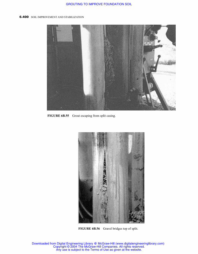
6.400 SOIL IMPROVEMENT AND STABILIZATION
FIGURE 6B.55 Grout escaping from split casing.
FIGURE 6B.56 Gravel bridges top of split.
Downloaded from Digital Engineering Library @ McGraw-Hill (www.digitalengineeringlibrary.com)Copyright © 2004 The McGraw-Hill Companies. All rights reserved.
Any use is subject to the Terms of Use as given at the website.
GROUTING TO IMPROVE FOUNDATION SOIL
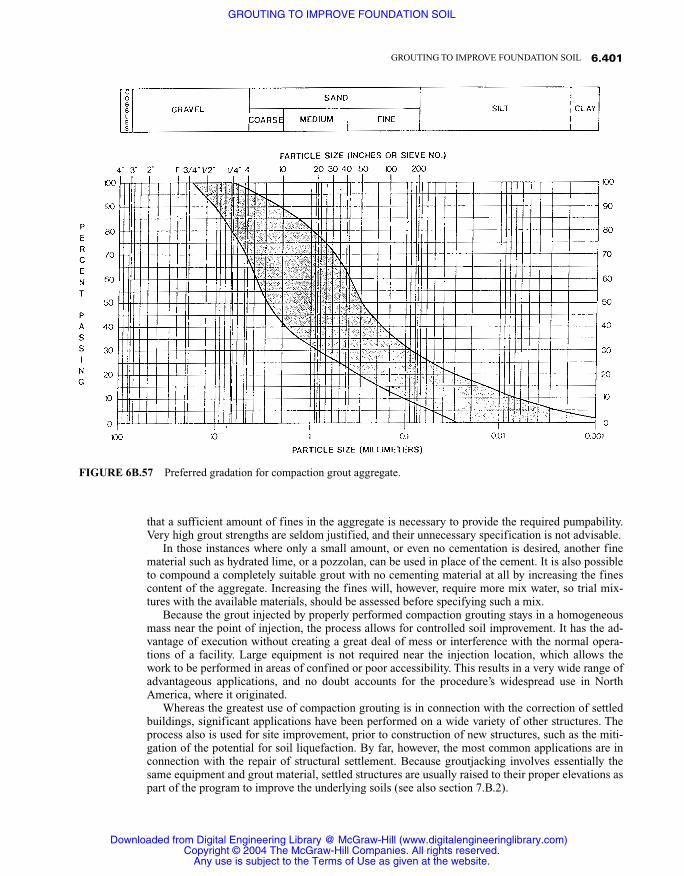
that a sufficient amount of fines in the aggregate is necessary to provide the required pumpability.Very high grout strengths are seldom justified, and their unnecessary specification is not advisable.
In those instances where only a small amount, or even no cementation is desired, another finematerial such as hydrated lime, or a pozzolan, can be used in place of the cement. It is also possibleto compound a completely suitable grout with no cementing material at all by increasing the finescontent of the aggregate. Increasing the fines will, however, require more mix water, so trial mix-tures with the available materials, should be assessed before specifying such a mix.
Because the grout injected by properly performed compaction grouting stays in a homogeneousmass near the point of injection, the process allows for controlled soil improvement. It has the ad-vantage of execution without creating a great deal of mess or interference with the normal opera-tions of a facility. Large equipment is not required near the injection location, which allows thework to be performed in areas of confined or poor accessibility. This results in a very wide range ofadvantageous applications, and no doubt accounts for the procedure’s widespread use in NorthAmerica, where it originated.
Whereas the greatest use of compaction grouting is in connection with the correction of settledbuildings, significant applications have been performed on a wide variety of other structures. Theprocess also is used for site improvement, prior to construction of new structures, such as the miti-gation of the potential for soil liquefaction. By far, however, the most common applications are inconnection with the repair of structural settlement. Because groutjacking involves essentially thesame equipment and grout material, settled structures are usually raised to their proper elevations aspart of the program to improve the underlying soils (see also section 7.B.2).
6.401GROUTING TO IMPROVE FOUNDATION SOIL
FIGURE 6B.57 Preferred gradation for compaction grout aggregate.
Downloaded from Digital Engineering Library @ McGraw-Hill (www.digitalengineeringlibrary.com)Copyright © 2004 The McGraw-Hill Companies. All rights reserved.
Any use is subject to the Terms of Use as given at the website.
GROUTING TO IMPROVE FOUNDATION SOIL

Faulty foundation soils and resulting settlement of literally thousands of light residential struc-tures have been corrected with compaction grouting. Included have been many large and even veryheavy buildings, including structures founded on both pile and large continuous raft foundations.Many successful applications have been made where settlement caused structural damage and re-sulted in vacation and in some cases condemnation of the structures. The four year old building ofManitou Springs Junior High School in Colorado had to be vacated in 1980, due to severe structuraldistress resulting from several inches of differential settlement. Compaction grouting not only im-proved the underlying faulty soil, but also jacked the building back to its proper elevation.
A portion of a five story high wing of a concrete building in Rapid City South Dakota had set-tled several inches, resulting in serious structural distress. In 1986, faulty soils to a depth of fiftyfeet were remediated under the shallow foundations, and the settled areas raised to their originalgrade while the structure remained fully occupied. In 1991, the four story high Inage Welfare Centerbuilding in Chiba City, Japan remained fully functional and occupied during the correction of near-ly three inches of differential settlement.
The first use of compaction grouting in connection of with a pile supported structure occurred in1966, in Hollywood, California. Settlement of the seventeen buildings of an apartment complex stillunder construction (Figure 6B.59) was occurring. The structures were built on a deep canyon fill,which had been deposited over a period of several decades. The fill consisted primarily of a varietyof uncompacted soils, but also included many large boulders, and a minor amount of organic waste.The foundation consisted of concrete grade beams supported by end bearing, bell bottom, cast inplace concrete piles. Investigation revealed that several of the piles, which varied in depth to morethan eighty feet, did not extend to a competent bearing layer as planned, and some actually terminat-ed in massive boulders embedded in the fill. It was considered imperative that no grout be depositedabove the pile tip elevation, as this would act negatively and increase the load on the already over-loaded end bearing piles.
6.402 SOIL IMPROVEMENT AND STABILIZATION
FIGURE 6B.58 Very stiff, mortar-like consistency grout.
Downloaded from Digital Engineering Library @ McGraw-Hill (www.digitalengineeringlibrary.com)Copyright © 2004 The McGraw-Hill Companies. All rights reserved.
Any use is subject to the Terms of Use as given at the website.
GROUTING TO IMPROVE FOUNDATION SOIL

Accordingly, prior to adoption of a full-scale grouting program, several holes were grouted adja-cent to four selected piles. The grout holes were spaced six feet apart, and placed either in a triangu-lar pattern of three holes or a square pattern of four. Grout was injected from the top down, in verti-cal stages of four feet, starting at the level of the pile tip. Between 12 and 22 cubic feet of grout wasinjected for each foot of depth. Following grout injection, large test borings were excavated adjacentto the four piles, and extending beyond the pile tips, allowing visual inspection. The photographshown as Figure 6B.60, was taken from one of the borings, which was about 60 feet deep. As can beobserved, grout was under the pile tip, as required, and only extended above that elevation by lessthan one foot.
Because this was a landmark project in the development of the compaction grouting process, ex-tensive other testing and observation was performed. Load tests (Figure 6B.61) to a level 1.5 timesthe design capacity were performed on several of the grouted piles, with virtually no further settle-ment. Regular inspections by the structural engineer and second-order optical surveys were madefor a period of 10 years following completion and occupancy of the buildings. No structural damagewas found during that period, and the maximum vertical settlement observed was less than 0.1 inch.
In projects such as this, where the grout deposition zone must not extend above a given level, it isimportant to “seal off ” the boundary by at least two stages of grout, injected from the top down.This is especially important in such instances as that cited, as injected grout will naturally tend toflow into the weaker soils. Where a considerable depth under the piles needs improvement, bottom-up procedures can be used once the upper boundaries have been established.
In another noteworthy case, friction piles were used for support of the West Orange County, Cal-ifornia, Municipal Courts Building (Figure 6B.62). The original geotechnical investigation providedfor the piles to extend from the surface to depths of 25 to 40 feet. Subsequent to the original investi-gation and prior to construction, the building was relocated approximately 100 feet to the west. It is
6.403GROUTING TO IMPROVE FOUNDATION SOIL
FIGURE 6B.59 Differential settlements of several inches occurred in the 17 buildings of thisapartment complex while still under construction.
Downloaded from Digital Engineering Library @ McGraw-Hill (www.digitalengineeringlibrary.com)Copyright © 2004 The McGraw-Hill Companies. All rights reserved.
Any use is subject to the Terms of Use as given at the website.
GROUTING TO IMPROVE FOUNDATION SOIL

6.404 SOIL IMPROVEMENT AND STABILIZATION
FIGURE 6B.60 Grout under pile tip.
FIGURE 6B.61 Load test in progress.
Downloaded from Digital Engineering Library @ McGraw-Hill (www.digitalengineeringlibrary.com)Copyright © 2004 The McGraw-Hill Companies. All rights reserved.
Any use is subject to the Terms of Use as given at the website.
GROUTING TO IMPROVE FOUNDATION SOIL

of contemporary design, basically a reinforced concrete frame with both concrete and masonrywalls. The floor and roof slabs are of reinforced concrete. Approximately two-thirds of the structureis one-story with a slab on grade floor, the remainder consisting of two structural floors above abasement. The foundation system consists of friction piles, cast in place, in driven corrugated steelshells. At the time of construction, the groundwater level was approximately at the basement floorelevation and, in fact, an extensive underfloor drainage system was installed to prevent the develop-ment of uplift pressures.
Distress was noted shortly after completion of construction. The building nonetheless remainedin full service until a major reinforced concrete roof girder fractured, eight years later. An investiga-tion disclosed that five inches of differential settlement had occurred, and that the structure was suf-fering from significant structural overstress. By moving the building from the originally planned lo-cation, the west half had inadvertently been placed over a wedge of very low density peat thatexisted only a few feet deeper than the pile tips, as illustrated in Figure 6B.63. As part of the investi-gation, individual piles were test loaded in increments up to twice their design capacity. Even withsupporting the imposed loads for five days, no significant deflection of the piles was observed. Itwas concluded that the settlement involved not only the structure and its pile foundation, but alsothe entire block of soil above the peat layer.
Compaction grouting was thus performed in the peat layer underlying the pile tips. Two inch I.D.casing was placed to the top of the peat layer, and grout injected in stages from the top down, untilgood bearing soil was encountered. Interestingly, the building remained open and in full serviceduring the work. The work was divided into five phases, each involving one courtroom and ancillaryfacilities. Access was through windows in the office areas adjacent to the courtrooms. Drilling ofthe grout holes, which were as deep as 65 feet ( m) was by hand-held, rotary wash, equipment (Fig-ure 6B.64), which could be quickly moved and operated throughout the otherwise restricted area.The grout pump remained outside the structure, and up to two hundred feet of hose was used toreach the furthest holes (Figure 6B.65).
6.405GROUTING TO IMPROVE FOUNDATION SOIL
FIGURE 6B.62 West Orange County Municipal Courts building underlain by faulty soil.
Downloaded from Digital Engineering Library @ McGraw-Hill (www.digitalengineeringlibrary.com)Copyright © 2004 The McGraw-Hill Companies. All rights reserved.
Any use is subject to the Terms of Use as given at the website.
GROUTING TO IMPROVE FOUNDATION SOIL

6.406 SOIL IMPROVEMENT AND STABILIZATION
FIGURE 6B.64 Drilling in restricted interior area withcompact hand-held drills.
FIGURE 6B.63 Cross section of building showing peat layer underlying pile tips.
Downloaded from Digital Engineering Library @ McGraw-Hill (www.digitalengineeringlibrary.com)Copyright © 2004 The McGraw-Hill Companies. All rights reserved.
Any use is subject to the Terms of Use as given at the website.
GROUTING TO IMPROVE FOUNDATION SOIL
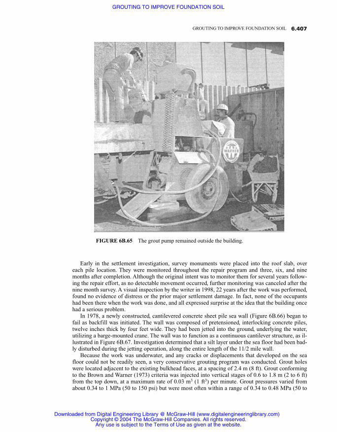
Early in the settlement investigation, survey monuments were placed into the roof slab, overeach pile location. They were monitored throughout the repair program and three, six, and ninemonths after completion. Although the original intent was to monitor them for several years follow-ing the repair effort, as no detectable movement occurred, further monitoring was canceled after thenine month survey. A visual inspection by the writer in 1998, 22 years after the work was performed,found no evidence of distress or the prior major settlement damage. In fact, none of the occupantshad been there when the work was done, and all expressed surprise at the idea that the building oncehad a serious problem.
In 1978, a newly constructed, cantilevered concrete sheet pile sea wall (Figure 6B.66) began tofail as backfill was initiated. The wall was composed of pretensioned, interlocking concrete piles,twelve inches thick by four feet wide. They had been jetted into the ground, underlying the water,utilizing a barge-mounted crane. The wall was to function as a continuous cantilever structure, as il-lustrated in Figure 6B.67. Investigation determined that a silt layer under the sea floor had been bad-ly disturbed during the jetting operation, along the entire length of the 11/2 mile wall.
Because the work was underwater, and any cracks or displacements that developed on the seafloor could not be readily seen, a very conservative grouting program was conducted. Grout holeswere located adjacent to the existing bulkhead faces, at a spacing of 2.4 m (8 ft). Grout conformingto the Brown and Warner (1973) criteria was injected into vertical stages of 0.6 to 1.8 m (2 to 6 ft)from the top down, at a maximum rate of 0.03 m3 (1 ft3) per minute. Grout pressures varied fromabout 0.34 to 1 MPa (50 to 150 psi) but were most often within a range of 0.34 to 0.48 MPa (50 to
6.407GROUTING TO IMPROVE FOUNDATION SOIL
FIGURE 6B.65 The grout pump remained outside the building.
Downloaded from Digital Engineering Library @ McGraw-Hill (www.digitalengineeringlibrary.com)Copyright © 2004 The McGraw-Hill Companies. All rights reserved.
Any use is subject to the Terms of Use as given at the website.
GROUTING TO IMPROVE FOUNDATION SOIL

70 psi). Approximately 0.3 m3 (10 cu ft) of grout was injected for each linear meter (3.0 ft) of bulk-head wall.
Two rows of cone penetrometer test probes were placed on the water side of the wall, wheredense soil was required for the cantilever to function. They were made both before and after thegrouting. The first row was approximately 1.5 m (5 ft) from the face of the bulkhead, with probesbeing made every 4.6 m (15 ft). The second row was 4.6 m (15 ft) off of the bulkhead, with probes at7.6 m (25 ft) intervals. The work was accomplished using a 10 ton capacity penetrometer secured toa floating barge, and the total penetration force included that portion of the weight of the barge lift-ed by the force acting on the penetrometer rods. When the rods could no longer penetrate, the bargewas lifted partly out of the water, which established refusal.
Cone tip resistance prior to grouting was less than 40 kg/cm2 (41 T/ft2) to a depth of 7 m (23 ft),
6.408 SOIL IMPROVEMENT AND STABILIZATION
FIGURE 6B.66 Cantilever sea wall tilted outward when backfill was ini-tiated.
Downloaded from Digital Engineering Library @ McGraw-Hill (www.digitalengineeringlibrary.com)Copyright © 2004 The McGraw-Hill Companies. All rights reserved.
Any use is subject to the Terms of Use as given at the website.
GROUTING TO IMPROVE FOUNDATION SOIL

and decreased to about 20 kg/cm2 (20 T/ft2) below that depth in the first row. In the second row, be-ginning values were less than 5 kg/cm2 (5 T/ ft2) to a depth of 7 m (23 ft), and about 20 kg/cm2 (20T/ft2) below that depth. The postgrouting value increased with depth in both rows to nearly 50kg/cm2 (51 t/ft2) at about 6 m (20 ft), below which refusal was reached at around 80 kg/cm2 (82T/ft2) at about 8 m (26 ft).
Compaction grouting was an especially suitable method of repair, as it did not require the use ofheavy equipment at the wall location, which was surrounded by water. Grout holes were drilled withhand-held pneumatically powered drills (Figure 6B.68). The grout pump remained on the adjoininggrade, with the delivery line supplying a standard header (Figure 6B.69). Extremely close control ofthe work was required, as deformation of the piles and resulting cracks could not be tolerated.Cracks in the piles would result in rapid corrosion of the prestressing tendons, due to the salt waterenvironment. Load cells, anchored to land-side deadmen, were used to monitor forces on the wall. Adiver was used continually during grout injection to monitor the sea bed for any displacements orgrout leakage. Because of the sensitivity of underwater injection, the pumping rate was limited toless than one cubic foot per minute. Grout pressures varied between 150 and 300 psi. Following theremedial work, the wall was backfilled, and the planned construction of a commercial center pro-gressed. The writer has visited the site several times since the work was done, and has always foundit to be performing well, with no indication of the former distress.
Compaction grouting is especially well suited for the densification of backfill material that wasnot properly compacted when originally placed. Many projects have been completed where faultyfills behind retaining walls, or around, and over buried pipelines have been improved. Figure 6B.70illustrates such a case, where settlement of the fill behind the basement wall of a shopping mall isbeing densified. As can be seen, the operation is fairly orderly, and there is relatively little interfer-ence to the shoppers, as the work is being done while the stores remain open.
Shortly after the original opening of the Japanese Pearl Divers attraction at Sea World in SanDiego, California, unacceptable leakage of a man-made lagoon threatened closure of the facility.The problem was the result of insufficient compaction of backfill materials surrounding the under-water viewing areas during original construction. Compaction grouting was used to densify thefaulty soils (Figure 6B.71). Most of the work was under raised decks and shops over the lagoon,with only about three feet of overhead clearance. Two inch diameter holes were drilled through the
6.409GROUTING TO IMPROVE FOUNDATION SOIL
FIGURE 6B.67 Cross section of sea wall installation as designed.
Downloaded from Digital Engineering Library @ McGraw-Hill (www.digitalengineeringlibrary.com)Copyright © 2004 The McGraw-Hill Companies. All rights reserved.
Any use is subject to the Terms of Use as given at the website.
GROUTING TO IMPROVE FOUNDATION SOIL

wood decks to allow drilling of grout holes to proceed from above. Once the hole at a given locationwas completed, wood plugs were placed to restore the deck. The grout mixer and pump were locatedoutside the park, about 600 feet distant from the work (Figure 6B.72), and the grout delivery hoseline was picked up at the end of each work shift, which was at night and the early morning hours pri-or to opening of the attraction. With exception of the absence of water in the lagoon, there was thusno indication of a problem to the visitors of the attraction, which remained open and fully opera-tional during the work. The project was monitored for several years following the work, with no fur-ther leakage or other distress noted.
The 1991 failure of a large sewer conduit in Houston, Texas, resulted in collapse of a road. In-vestigation established that the backfill around and overlying some 8000 feet of the pipe was of verylow density. The silty and clayey sand backfill was found to have Standard Penetration Test “N” val-ues averaging 12, with many below 10. Compaction grout was injected through rows of holes oneach side of the pipe, at ten foot centers. Verification that the specification requirements of im-provement to an average Standard Penetration Test N value of 20 with no test below 15 were easily
6.410 SOIL IMPROVEMENT AND STABILIZATION
FIGURE 6B.68 Drilling of underwater grout holes.
Downloaded from Digital Engineering Library @ McGraw-Hill (www.digitalengineeringlibrary.com)Copyright © 2004 The McGraw-Hill Companies. All rights reserved.
Any use is subject to the Terms of Use as given at the website.
GROUTING TO IMPROVE FOUNDATION SOIL

6.411GROUTING TO IMPROVE FOUNDATION SOIL
FIGURE 6B.69 Grout injection header.
FIGURE 6B.70 Grouting faulty backfill in shopping center.
Downloaded from Digital Engineering Library @ McGraw-Hill (www.digitalengineeringlibrary.com)Copyright © 2004 The McGraw-Hill Companies. All rights reserved.
Any use is subject to the Terms of Use as given at the website.
GROUTING TO IMPROVE FOUNDATION SOIL

6.412 SOIL IMPROVEMENT AND STABILIZATION
FIGURE 6B.71 Grouting under tourist attraction with littleevidence of the ongoing work visible.
FIGURE 6B.72 Grout pump and big equipment are out of sight.
Downloaded from Digital Engineering Library @ McGraw-Hill (www.digitalengineeringlibrary.com)Copyright © 2004 The McGraw-Hill Companies. All rights reserved.
Any use is subject to the Terms of Use as given at the website.
GROUTING TO IMPROVE FOUNDATION SOIL

met. One hundred thirty-four postgrouting SPT tests, made between the grout holes by the samedrill rig and operator, produced N values averaging 22.3.
In another case, CPT testing was used to evaluate the appropriateness of compaction grouting todensify loose backfill soil around and underlying several miles of distressed storm drain pipe. Thebackfill materials were fine to medium sand and silty sand, with silt and clayey silt lenses. Thedrains were under the pavement of a major freeway, and had resulted in surface settlement so greatthat lanes had to be closed to traffic. Cone penetrometer testing disclosed cone tip resistance (Qc) ofthe defective soils, generally less than 30 tons/ft2 (29 kg/cm2). Resistance on the order of at least 50tons/ft2 (49 kg/cm2) would be required to prevent settlement. The test section involved injection of9.5 m3 (318 ft3) of grout into 32 injection points spaced at 2.1 m (7 ft) on center, using a maximumgrout pressure of 2.8 MPa (400 psi). Details as to the aggregate gradation and pumping rate of thework, which was done on an emergency basis, are not known. The required, after grouting, mini-mum CPT values, of 50 tons/ft2 (49 kg/cm2) were easily met, as illustrated in Figure 6B.73.
As a result of the successful test application, a contract was let to improve the soil around sever-al miles of the storm drains. Bottom plugged, two inch, proprietary, flush wall casing was driven onseven foot centers (Figure 6B.74) in rows on each side of the drains. Prior to injection, the casingwas raised about one foot and the plug knocked out. Grout was then pumped at a rate of less than0.04 m3 (1.5 ft3) per minute. As in the previous example, CPT tests were taken both before and afterthe grout injection. The required degree of soil improvement was easily achieved.
Compaction grouting is often used to raise the density of granular soils, for the purpose of miti-gating the risk of liquefaction during earthquakes. In 1983, compaction grouting was used to im-prove the site for an addition to an existing pile-supported hospital building. Because the work wasimmediately adjacent to the existing structure, which remained fully operational, excessive noise or
6.413GROUTING TO IMPROVE FOUNDATION SOIL
FIGURE 6B.73 CPT values before and after grout-ing of faulty trench backfill.
Downloaded from Digital Engineering Library @ McGraw-Hill (www.digitalengineeringlibrary.com)Copyright © 2004 The McGraw-Hill Companies. All rights reserved.
Any use is subject to the Terms of Use as given at the website.
GROUTING TO IMPROVE FOUNDATION SOIL

vibration could not be tolerated. Of the several candidate methods evaluated, compaction groutingwas the only one that met these requirements. The upper level of the soils from 7 to 17 feet in depthwas first grouted. Then the remaining soils were treated from the bottom up, starting at the bottomof the liquefiable sands at a depth of 34 feet.
Prior to construction of the addition, grout holes were drilled on a square grid over the entire site(Figure 6B.75). The holes were spaced eight feet apart, and average grout take was 2.7 cubic feet ofgrout for each foot of hole. The grout was composed of silty sand, cement, and water mixed to a stiffconsistency, with slump between 25 to 50 mm (1 to 2 in). Postinjection testing indicated an increasein the density of the in-place soils of about 20%. The site was in an area that experienced wide-spread damage from the Loma Prieda earthquake in 1989. The hospital site performed well and noindication of liquefaction was evident.
In 1988, compaction grouting was used to densify foundation soils underlying Chessman Dam,near Helena, Montana. This was the first of many similar projects in which compaction grouting hasbeen employed to upgrade the seismic resistance of dams and other large civil works. In 1999, amassive project was started to improve the soil underlying the Narita airport, which serves Tokyo,Japan, in order to mitigate the risk of liquefaction. That effort will involve one of the largest under-takings to date, in terms of amount of grout used and volume of soil treated.
Another area, in which compaction grouting has been found advantageous, is prevention of sur-face damage as a result of soft ground tunneling. A phenomenon is well understood wherein atrough of soil overlying such tunnels occurs as the tunnel shield passes. This zone of disturbed soilstarts directly over the tunnel and extends up and out until it reaches the surface. It will often extendbeyond the foundations of adjacent structures, and can be very damaging, not only to the structures,but also to underground pipes and utilities within the zone of disturbance.
In 1980, a large evaluation program was conducted in the early stages of construction of theBolton Hills tunnel, part of the Baltimore Metro project. A test application was conducted in a sec-tion of the actual tunnel where the adjacent structures were of minimal value. Compaction grouting
6.414 SOIL IMPROVEMENT AND STABILIZATION
FIGURE 6B.74 Driving grout injection casing.
Downloaded from Digital Engineering Library @ McGraw-Hill (www.digitalengineeringlibrary.com)Copyright © 2004 The McGraw-Hill Companies. All rights reserved.
Any use is subject to the Terms of Use as given at the website.
GROUTING TO IMPROVE FOUNDATION SOIL

was performed immediately over the tunnel shield as it progressed. This was accomplished througha single row of grout holes, which were drilled from the surface of the street above and extended towithin about five feet of the crown of the tunnel (Figure 6B.76). A single stage of grout was injectedimmediately after the shield passed, in the tunnel below. The trial, which included extensive instru-mentation and evaluation of the adjacent soils, was so successful that the method was adopted forprotection of the historical and irreplaceable structures on the remainder of the tunnel route.
Since that early experience, compaction grouting has been used in a similar manner on a numberof other significant tunnels constructed in both North and South America. It was also specified foruse in construction of the Taipei Metro, in Taipei, Taiwan, Republic of China.
Another extensive use of compaction grouting is in connection with distressed buried pipelines.In 1976, a 96 inch drainage conduit, which was badly overstressed and deformed as a result of ex-cessive loading, was repaired with compaction grouting. Because access to the overlying area wasnot available, all work was done from within. Twelve foot long, radial holes were drilled with hand-held equipment from within the conduit (Figure 6B.77). Grout was then pumped in stages of aboutone foot, from the bottom out. Excessive deformations of the pipe were removed during the groutinjection.
In 1977, the heading of a flexible liner plate tunnel, which was under construction, began to sinkuncontrollably. Compaction grout was injected to stabilize a highly organic silt layer found to ex-tend from the invert of the tunnel, a depth of about 12 feet. Once the faulty ground was sufficientlyimproved, the heading of the tunnel was grout jacked back to its proper elevation. All of the workwas done from within the tunnel (Figure 6B.78), as no disturbance of traffic on the major highwayabove was allowed.
In 1991, the process was used to stabilize defective soil underlying an 84 inch diameter con-duit, connecting to a water treatment plant in Des Moines, Iowa. The plant had been underpinnedwith micro-piles; however, such piles could not be readily tied to the round pipe section. The
6.415GROUTING TO IMPROVE FOUNDATION SOIL
FIGURE 6B.75 Small track-mounted rig used for drilling grout holes.
Downloaded from Digital Engineering Library @ McGraw-Hill (www.digitalengineeringlibrary.com)Copyright © 2004 The McGraw-Hill Companies. All rights reserved.
Any use is subject to the Terms of Use as given at the website.
GROUTING TO IMPROVE FOUNDATION SOIL

6.416 SOIL IMPROVEMENT AND STABILIZATION
FIGURE 6B.76 Injection of grout to densify soils as theyloosen.
FIGURE 6B.77 Drilling of 12 foot long radial grout holes from inside drainageconduit.
Downloaded from Digital Engineering Library @ McGraw-Hill (www.digitalengineeringlibrary.com)Copyright © 2004 The McGraw-Hill Companies. All rights reserved.
Any use is subject to the Terms of Use as given at the website.
GROUTING TO IMPROVE FOUNDATION SOIL

grouting was used to not only stabilize the underlying soil, but to jack the pipe up to its correctlevel as well.
Perhaps the most sensitive of any geotechnical remedial applications involves work in water-re-taining embankments. Should excessive pore pressures develop, uplift leading to complete failure ofthe embankment could occur. Obviously, should hydraulic fracturing occur, leakage through the em-bankment would present an extreme risk, which could also lead to complete failure. Because com-paction grouting allows for close control of the grout deposition location, when properly performed,it is one of the safest remedial procedures for correcting defects in such embankments. In order toachieve the maximum assurance against creating hydraulic fracturing, careful design and rigid con-trol of the grout mix to be used is of crucial importance. In this regard, a minimum of 25% of thegrout aggregate should be larger than a number 4 sieve. Additionally, the aggregate should be com-pletely free of any clay component.
In 1996, a sinkhole developed in the core of Bennett Dam (Figure 6B.79), which is in the north-ern part of British Columbia, Canada. Bennett is one of the largest embankment dams in the world.Extensive investigation determined the disturbed zone to be generally less than 20 feet across, butabout 400 feet deep. The investigation also uncovered a second sinkhole of somewhat less magni-tude. After much deliberation, compaction grouting was selected as the best method for remediationof the defect.
This was a critical problem and warranted the very best design and remedial implementation.Extensive investigation was made to accurately map the sinkholes. To monitor any changes of con-dition within the embankment or surface profile, an extensive installation of instrumentation wasinstalled. Requirements for continuous computer monitoring (Figure 6B.80) of the parameters ofboth the drilling and the grout injection were adopted. Continuous analysis of the retrieved data wasmade, along with appropriate adjustments in the conduct of the work.
6.417GROUTING TO IMPROVE FOUNDATION SOIL
FIGURE 6B.78 Settlement correction to heading of liner plate tunnel.
Downloaded from Digital Engineering Library @ McGraw-Hill (www.digitalengineeringlibrary.com)Copyright © 2004 The McGraw-Hill Companies. All rights reserved.
Any use is subject to the Terms of Use as given at the website.
GROUTING TO IMPROVE FOUNDATION SOIL

6.418 SOIL IMPROVEMENT AND STABILIZATION
FIGURE 6B.79 Bennett dam in British Columbia, Canada, one of the worlds largest earth embankment dams.
FIGURE 6B.80 Continuous real time computer monitoring.
Downloaded from Digital Engineering Library @ McGraw-Hill (www.digitalengineeringlibrary.com)Copyright © 2004 The McGraw-Hill Companies. All rights reserved.
Any use is subject to the Terms of Use as given at the website.
GROUTING TO IMPROVE FOUNDATION SOIL

Compaction grouting had not been previously accomplished to such depths or under such sensi-tive conditions, and huge losses would result if the embankment were breeched during the repair.Additionally, the work was to be done in severe cold weather, during the winter months. This wouldrequire protective, heated enclosures (Figure 6B.81). Thus, a full-scale test hole was drilled and in-jected, at a site of similar soil materials in Vancouver, prior to any work being accomplished on thedam itself. Among the objectives of the test hole were to assure that the proposed drilling and grout-ing methods, which were to be continuously electronically monitored, could meet the specificationrequirements. The hole was required to be within 1% percent of verticality over its entire length.The drilling method also had to prevent any positive liquid head from being imposed within the em-bankment.
Further objectives of the test hole were to confirm pumpability of the proposed grout mix, whichwas to contain a minimum of 25% of aggregate retained on a number 4 sieve. The aggregate wasalso to be essentially free of clay. Creation of a hydraulic fracture signature, by intentionally pump-ing too fast and/or adding clay to the grout, was also an important objective. This would allow thepersonnel who would be monitoring the actual work on the dam to become more familiar with areasdeserving special alertness. All objectives of the test hole were realized and additional shortcomingsof the contractor’s operation were identified. Although it represented a considerable cost, the testproved to be extremely valuable to the overall operation, and is credited with enabling the successfulcompletion of the work.
To accurately drill the grout holes, a powerful dual rotary drill rig, such as might be used for wa-ter well drilling, was used (Figure 6B.82). It was capable of simultaneously turning both the drillstring and the casing in opposing directions. A heavy 6 inch steel casing, was used, and the jointswere welded to assure tightness and proper alignment. The completed holes were checked for verti-
6.419GROUTING TO IMPROVE FOUNDATION SOIL
FIGURE 6B.81 Cold weather enclosures.
Downloaded from Digital Engineering Library @ McGraw-Hill (www.digitalengineeringlibrary.com)Copyright © 2004 The McGraw-Hill Companies. All rights reserved.
Any use is subject to the Terms of Use as given at the website.
GROUTING TO IMPROVE FOUNDATION SOIL

cality with a gyro instrument, and found to be well within the required 1% tolerance. The contractorhad originally proposed to inject the grout directly through the 6 inch casing, however it was foundthat the grout would exert a positive pressure of about 0.3 psi for each vertical foot. This could resultin unacceptable pressures at the bottom of the hole, so a smaller HWL 4 inch ID, flush wall casingwas inserted and sealed off at the bottom of the hole with a packer. With the smaller casing, a nega-tive pressure of about 0.3 psi per foot was experienced.
Analysis indicated that in order to preclude excessively high pore pressures developing in theembankment, as very slow pumping rate of less than 0.5 cubic feet (14 L) of grout per minute, wasrequired. The grout was injected from the bottom up, in stages of one foot (0.3 m). The 6 inch casingand the contained HWL grout tube were pulled by the drill rig for each stage. As each 20 foot incre-ment was withdrawn, the 6 inch casing was cut with a pipe cutter, the threaded HWL casing jointbroken, and the header rejoined by welding for the next pull. As expected, the grout take was quitevariable, due to the variation of the sinkhole boundaries. Required grout pressure for these verydeep holes was on the order of 1400 psi (9660 kPa).
An extensive array of piezometers was installed around the sinkholes prior to grout injection,and pore pressures closely monitored throughout the work. Occasional excessive pressure did re-quire a pause of grout injection in the early stages of the work. This was the result of the contractorexceeding the specified pumping rate. Once he obtained a proper grout pump, and his crew gainedexperience, the injection proceeded at a rate of about 0.33 cubic feet per minute (8.6 L/min), with-out further problems. As part of the final remedial work, the soil cap material was excavated downto the top of the injected grout. The grout was found to exist in a perfect columnar mass, as expect-ed (Figure 6B.83). The success of this project proved the engineering validity of a properly designedand controlled compaction grouting program.
Another interesting application of compaction grouting in a water-retaining embankment was
6.420 SOIL IMPROVEMENT AND STABILIZATION
FIGURE 6B.82 Powerful rotary wash drill rig handled casing easily.
Downloaded from Digital Engineering Library @ McGraw-Hill (www.digitalengineeringlibrary.com)Copyright © 2004 The McGraw-Hill Companies. All rights reserved.
Any use is subject to the Terms of Use as given at the website.
GROUTING TO IMPROVE FOUNDATION SOIL
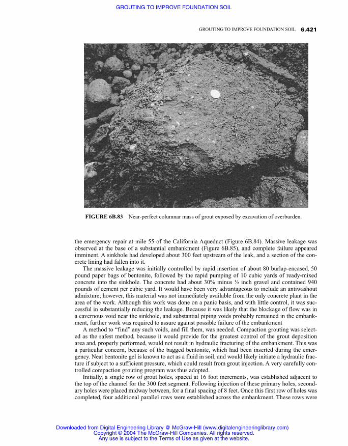
the emergency repair at mile 55 of the California Aqueduct (Figure 6B.84). Massive leakage wasobserved at the base of a substantial embankment (Figure 6B.85), and complete failure appearedimminent. A sinkhole had developed about 300 feet upstream of the leak, and a section of the con-crete lining had fallen into it.
The massive leakage was initially controlled by rapid insertion of about 80 burlap-encased, 50pound paper bags of bentonite, followed by the rapid pumping of 10 cubic yards of ready-mixedconcrete into the sinkhole. The concrete had about 30% minus ½ inch gravel and contained 940pounds of cement per cubic yard. It would have been very advantageous to include an antiwashoutadmixture; however, this material was not immediately available from the only concrete plant in thearea of the work. Although this work was done on a panic basis, and with little control, it was suc-cessful in substantially reducing the leakage. Because it was likely that the blockage of flow was ina cavernous void near the sinkhole, and substantial piping voids probably remained in the embank-ment, further work was required to assure against possible failure of the embankment
A method to “find” any such voids, and fill them, was needed. Compaction grouting was select-ed as the safest method, because it would provide for the greatest control of the grout depositionarea and, properly performed, would not result in hydraulic fracturing of the embankment. This wasa particular concern, because of the bagged bentonite, which had been inserted during the emer-gency. Neat bentonite gel is known to act as a fluid in soil, and would likely initiate a hydraulic frac-ture if subject to a sufficient pressure, which could result from grout injection. A very carefully con-trolled compaction grouting program was thus adopted.
Initially, a single row of grout holes, spaced at 16 foot increments, was established adjacent tothe top of the channel for the 300 feet segment. Following injection of these primary holes, second-ary holes were placed midway between, for a final spacing of 8 feet. Once this first row of holes wascompleted, four additional parallel rows were established across the embankment. These rows were
6.421GROUTING TO IMPROVE FOUNDATION SOIL
FIGURE 6B.83 Near-perfect columnar mass of grout exposed by excavation of overburden.
Downloaded from Digital Engineering Library @ McGraw-Hill (www.digitalengineeringlibrary.com)Copyright © 2004 The McGraw-Hill Companies. All rights reserved.
Any use is subject to the Terms of Use as given at the website.
GROUTING TO IMPROVE FOUNDATION SOIL

6.422 SOIL IMPROVEMENT AND STABILIZATION
FIGURE 6B.85 Leakage was at the base of the embankment.
FIGURE 6B.84 Mile 55 of the California Aqueduct during the emergency grouting repairs.
Downloaded from Digital Engineering Library @ McGraw-Hill (www.digitalengineeringlibrary.com)Copyright © 2004 The McGraw-Hill Companies. All rights reserved.
Any use is subject to the Terms of Use as given at the website.
GROUTING TO IMPROVE FOUNDATION SOIL

about 8 feet apart, with holes located at a spacing of 8 feet. They were grouted using split spacing,with a primary–secondary order of injection.
Grout was prepared using aggregate of the preferable gradation, containing about 25% graveland about 10% cement. It was injected from the bottom up, in one foot stages, at a conservativelylow rate of one-half cubic foot per minute. Because of the sensitivity of the work, which was donewith the aqueduct in continuous operation, continuous monitoring of the embankment was carriedout. In addition to careful observation and recording of the grout injection parameters, this monitor-ing included a manometer level control system and continual observation of the ground surface andexposed top portion of the canal lining by optical survey, which is evident in Figure 6B.86, showingthe work in progress.
Because of the emergency conditions, the grouting crews arrived within one day of discovery ofthe problem. They worked 24 hours a day until the work was essentially completed. The rapid mobi-lization precluded continuous computer monitoring, which would have been preferred. Very care-fully made manual records were kept, however, which were entered into a computer database imme-diately upon completion of injection of each hole. Graphical printouts thereof were assembled onthe wall of the trailer office (Figure 6B.87), so that the actual conditions as dictated by the grout in-jection behavior could be easily observed. The work was a success in that it allowed the aqueduct tofunction for several months until a scheduled shutdown. A permanent repair consisting of a continu-ous membrane protected by a shotcrete overlay was then made.
Concurrently with the start of grouting, a subsurface geological investigation, which eventuallyincluded 12 carefully logged bore holes and one test pit, was made. It was determined that the em-bankment had been founded on soil materials underlain by a gypsiferous formation. The pipingleakage was determined to most likely be the result of solution of the gypsiferous materials fromwater permeating through an overlying sand stratum, which was under the embankment fill. This
6.423GROUTING TO IMPROVE FOUNDATION SOIL
FIGURE 6B.86 Remedial grouting in progress. Note survey activity to ensure against any surfaceheave or other movement.
Downloaded from Digital Engineering Library @ McGraw-Hill (www.digitalengineeringlibrary.com)Copyright © 2004 The McGraw-Hill Companies. All rights reserved.
Any use is subject to the Terms of Use as given at the website.
GROUTING TO IMPROVE FOUNDATION SOIL

conclusion was supported by the results of the grouting program. Therein, the majority of the groutwas injected at depths greater than those of the fill and extended throughout a plan area muchgreater than could be reasonablly represented by typical piping leakage. A total of 4523 cubic feet(125 m3) of grout was injected into 281 holes extending through the embankment. Careful recordsof grout take and behavior were kept and promptly reviewed. They confirmed that the voiding wasmuch more extensive than originally thought and that, indeed, it was in the original soils underlyingthe embankment itself. Figure 6B.87 shows the records for the individual holes, assembled in a col-lage, on the wall of the office trailer. Thereon, the grout take is indicated by a horizontal bar at eachrespective depth, such that the actual configuration of the voiding can be readily visualized.
As a final note, compaction grouting need not be messy. Figure 6B.88 shows a grout hole casing,within inches of sensitive laboratory equipment in the Spalding Research Laboratory at the Califor-nia Institute of Technology in Pasadena, California. With reasonable care (note that the equipment iswrapped in plastic sheeting), compaction grouting can be successfully conducted under even themost sensitive environments.
6B.6.3 PERMEATION GROUTING
Permeation grouting is the longest established and most widely used grouting technique. In soils,the procedure involves permeating and filling the soil pore spaces, without any significant distur-bance to, or movement of, the individual soil grains. The structure and dimensions of the soil porespaces dictate the type of grout that can be effectively used. The particles of most fluid suspensiontype grouts containing ordinary portland cement and are too large to penetrate any but the coarsest
6.424 SOIL IMPROVEMENT AND STABILIZATION
FIGURE 6B.87 Posted records facilitated analysis and evaluation.
Downloaded from Digital Engineering Library @ McGraw-Hill (www.digitalengineeringlibrary.com)Copyright © 2004 The McGraw-Hill Companies. All rights reserved.
Any use is subject to the Terms of Use as given at the website.
GROUTING TO IMPROVE FOUNDATION SOIL

soil materials, limiting their use to reasonably clean coarse sands and gravels. Accordingly, perme-ation grouting of most soil is performed with either highly penetrable chemical solutions or ultra-fine cement grouts. Outside the United States, principally in Europe, clay, combinations of clay andcement, or chemical solution grouts have also been extensively used.
This type of grouting is generally limited to sands and sandy soils containing minor amounts offiner particles. Whereas suitable grouts can be injected into fine sands and silts, slower injectionrates are required than in the more permeable coarser-grained materials. The slower injection addsto both the required time for placement and cost of the work, which sometimes preclude its use. Per-meation grouting of soil is generally more expensive than is compaction grouting. Its use is thuscommonly limited to applications where a considerable increase in the cohesion, rather than thedensity, of the granular material is required, or in clean, coarse materials, which are not appropriatefor compaction grouting.
The largest single use of permeation grouting is for temporary solidification of low-cohesionsandy soils as an aid to construction, or to reduce or eliminate soil disturbance or failure resultingfrom excavation. Figure 6B.89, illustrates such a case; here a self-supporting buttress of solidifiedsoil enabled a nearly shear cut to be made for the basement of a new building. Permeation groutingis also seeing ever-increasing use for mitigation of the liquefaction potential of in situ soils as a re-sult of earthquakes. The procedure is also occasionally used to permanently increase the load-bear-ing capacity of appropriate soils.
Another significant area of use for permeation grouting is for reduction of permeability or con-trol of the flow of water through a soil formation. Both ultrafine cement and chemical solutiongrouts are so used. Fine fillers, such as silica fume and ultrafine cement, are sometimes mixed intosolution grouts to increase their strength, alter their properties, or lessen their cost. Expanding
6.425GROUTING TO IMPROVE FOUNDATION SOIL
FIGURE 6B.88 Work around sensitive equipment in a research laboratory.
Downloaded from Digital Engineering Library @ McGraw-Hill (www.digitalengineeringlibrary.com)Copyright © 2004 The McGraw-Hill Companies. All rights reserved.
Any use is subject to the Terms of Use as given at the website.
GROUTING TO IMPROVE FOUNDATION SOIL

knowledge, more reliable and durable strength, and increasing availability of ultrafine cements haveresulted in their increased use for permeation grouting, and they are now preferred over the moretraditional chemical solution grouts by many professionals.
6B.6.3.1 Fluid Suspensions for StrengtheningFluid suspension grouts were the first grouts to ever be used and continue to be widely employed.The largest area of use for these grouts is in the filling of cracks and joints in rock, although theiruse has been extended greatly and includes controlled injection into soil. In the simplest form, a sus-pension of ordinary portland cement and water is mixed. High-shear mixing is required to thorough-ly disperse the cement particles, and continuous agitation of the mixed grout is required to maintainthe individual grains in suspension.
Grout mix design is expressed as the ratio of water to cementitious solids, either by weight or byvolume. Volume measurements have been the most often used traditionally, as they were very easyto make when using bagged cement that contains one cubic foot of dry powder. Where bulk cementis used, proportioning by weight is more convenient. In the United States, grout mixtures as thin as10:1 by volume have been extensively used historically. Many, including the writer, consider suchthin grouts to be little more than dirty water, and extensive testing and research by the author andothers (Houlsby, 1982; Weaver, 1991) have shown such thin mixtures to provide little durability.Current thinking suggests that thicker mixtures (maximum W/C 3:1 by volume) are far more appro-priate for most applications. In a well-documented discussion of appropriate water to cement ratios,Houlsby (1982) concluded that W/C 2:1 by volume has been used on thousands of projects and wasoptimal for general use.
Although unmodified common cement–water suspensions continue to be widely used, they suf-fer from settlement of the solids, resulting in accumulation of mix water at the top of unagitatedgrout. This is known as bleed and is an important factor to consider in any grout formulation. In thisregard, the amount of shear subjected during the mixing of the grout has an important bearing uponthe resulting bleed. When cement and water come together, the cement grains tend to clump or floc
6.426 SOIL IMPROVEMENT AND STABILIZATION
FIGURE 6B.89 Solidification of in situ soils into a self-supporting buttress negated theneed for any other support of this excavation in wind-deposited, cohesionless fine sands.
Downloaded from Digital Engineering Library @ McGraw-Hill (www.digitalengineeringlibrary.com)Copyright © 2004 The McGraw-Hill Companies. All rights reserved.
Any use is subject to the Terms of Use as given at the website.
GROUTING TO IMPROVE FOUNDATION SOIL

together. To minimize the amount of bleed of a particular grout, high-shear mixing is required so asto break up and separate the individual cement grains. This factor was thoroughly discussed byKravetz (1959). The essence of his conclusions, as reported by Houlsby, (1990) are:
1. Cement grains, when mixed with water, tend to aggregate and form clumps. This slowsthe wetting process, as does air attached to the grains. The effect of high-speed shearing orlaminating, plus the centrifugal effect, is to thoroughly break up the clumps and to sepa-rate air bubbles. As a result, each individual grain is rapidly and thoroughly wetted and putinto suspension.
2. During cement hydration, needle-like or spring-like elements of hydrates form on the su-perficial layer of each wetted grain of cement. In a high-speed mixer, the laminating effectand high-speed rotation keeps breaking these hydrates away from the grain of cement,thus exposing new areas to the water and consequently bringing the formation of new ele-ments. These hydrate elements are of colloidal size, and as the amount of these elementsin the mixture increases, the grout becomes colloidal in character.
In reality, virtually no common cementitious suspension grout is truly colloidal, as even well-dispersed cement grains will settle in water unless special admixtures are used, as will be subse-quently discussed. High-shear mixing will greatly reduce and can in thick grouts nearly eliminatebleeding. In some places, but generally not in the United States, grout that exhibits little or no bleedis regarded as an “stable.” Stable grouts are generally defined as those that exhibit a total of no morethan 5% bleed. European practice commonly calls for “stable” grouts, which typically include a fewpercent of bentonite, to act as a suspension agent. Whereas bentonite inclusion will tend to lessenthe cement grain settlement and resulting bleed, there are significant disadvantages to its use. Mod-ern admixture technology offers a variety of formulations that can minimize bleed without the unde-sirable aspects of admixed bentonite. This will be subsequently discussed in more detail.
Suspension grouts of ultrafine cement and water are significantly more penetrating than thosemade with Type 3 cement, which is the finest of the common cements, and some ultrafines can formnearly colloidal mixes. These can be readily injected into sandy soils, as illustrated in Figure 6B.90.Because of the minute grain size of ultrafine cements, they provide very large specific surface ar-eas. Inclusion of a high-range, water-reducing admixture in these grouts is virtually required, andwill result in much better dispersal of the individual cement particles. This will substantially reducethe propensity for pressure filtration in the soil. It will also dramatically increase the specific sur-face area of the cement available for the water to contact, resulting in much increased hydration ac-tivity, and higher ultimate strength.
There are two main types of ultrafine cement—those based on slag and those based on portlandcement. Although the two are comparable in many respects, there is a fundamental difference in thespan of hydration and the resulting setting time. Because of the very high specific surface area of ul-trafine cement based on portland cement, hydration activity is very high, resulting in rapid settingand strength gain. For this reason, retarding admixtures are sometimes included in the cement to de-lay the otherwise rapid setting. Portland cement combined with some common retarders can be ex-tremely sensitive to temperature, so the proportions of the additive must be accurately dosed and ap-propriately matched to the temperature of both the injection environment and the formation beinggrouted. Problems with flash set and difficulties with both setting time and rate of strength gainhave been reported when using some of the earlier ultrafine cements based on portland cement.
Cements based on slag tend to set and gain strength much slower than their portland cementcousins. Thus, retardation is seldom a problem, but accelerating admixtures may be required insome instances. Well-established accelerators are available and their behavior is quite predictable,so time of setting is not much of a problem with slag-based ultrafines. It is only in recent times thatultrafine cements have become commonly available. With their ever-increasing use and accumulat-ed field experience, continuous improvement in the available products is occurring, and continualmonitoring is required to keep up with the latest technology.
Most ultrafine cements are composed of a range of differently sized particles. Providing they are
6.427GROUTING TO IMPROVE FOUNDATION SOIL
Downloaded from Digital Engineering Library @ McGraw-Hill (www.digitalengineeringlibrary.com)Copyright © 2004 The McGraw-Hill Companies. All rights reserved.
Any use is subject to the Terms of Use as given at the website.
GROUTING TO IMPROVE FOUNDATION SOIL

well dispersed, some larger particles are acceptable for grouts that will be used to fill obvious frac-tures and voids, as long as the largest particles are smaller than the thickness of the defect. In thepermeation of granular soil, however, because the soil itself acts as a filter, the larger-sized particlesof the grout can build up as they are pushed into the soil, initiating the formation of a filter cake.The size, and the proportion, of the larger grains of ultrafine cement used for permeation groutingof soil is thus of great importance. Obviously, use of a cement with the smallest mean particle sizeand a minimal amount of larger particles is desirable for soil grouting. The particle size distributionof several different ultrafine cements as well as Type III common cement are shown in Figure6B.91.
It should be noted that not all type III cement has the same grain size distribution. ASTM C 150“Specification for Portland Cement” calls only for Blaine fineness of the specific surface area. Acompliant Blaine value can be obtained with a fairly wide range of grain size distribution. The TypeIII curve provided in Figure 6B.91 is for an actual batch of cement produced at one given plant.
6B.6.3.2 Chemical Solution Grouts for StrengtheningAnother form of strengthening is adhesion of the individual soil grains with a chemical solutiongrout. There are a variety of chemical solution grouts available, but they all work in essentially thesame manner. A base material, which usually represents the majority of the final mix and is often di-luted with water, is combined with one or more reactant materials. The base part is usually fluid,whereas the reactants can be either liquid or powder depending upon the individual grout formula-
6.428 SOIL IMPROVEMENT AND STABILIZATION
FIGURE 6B.90 Ultrafine cement grout used to solidify cohesion-less sand allows excavation under the foundations of a structure.
Downloaded from Digital Engineering Library @ McGraw-Hill (www.digitalengineeringlibrary.com)Copyright © 2004 The McGraw-Hill Companies. All rights reserved.
Any use is subject to the Terms of Use as given at the website.
GROUTING TO IMPROVE FOUNDATION SOIL

tion. At some period of time, after mixing the base and reactants together, setting occurs and the in-jected solution turns either to a foam, gel, or solid state. The setting time can be instantaneous toseveral hours or even days, depending upon the individual system used and the proportion of the in-dividual ingredients thereof.
Many chemical grouts are mixed and pumped as single solutions, whereas the different compo-nents of others are individually pumped and stream mixed at the injection point (Figure 6B.92).There are many manufacturers of proprietary chemical grout formulations, especially those used forcontrol of water movement within the soil or into underground substructures. For strengthening ap-plications, especially where large quantities of grout are required, most specialty contractors tend topurchase the individual chemical components separately and mix them on the job site near the pointof injection. Although some specialists represent their formulations as something very special and“proprietary” (a word greatly overused, in the writers opinion), the vast majority of grouts used forstrengthening of soil throughout the world involve sodium silicate as the base material. There are,however, a wide variety of different reactant systems, most of which are well known and readilyavailable.
For the strengthening of soils, the most important parameters for selection of a chemical solutiongrout are injectability, strength, safety of use, and cost. Hard, rigid gels are desired, as they providethe greatest stiffness as well as providing good strength. Cost can also be an important factor be-cause this type of work is often performed on a massive basis, where very large quantities of groutare involved. With these factors in mind, grouts based on sodium silicate are particularly suitableand most frequently used for strengthening applications. Appropriately, the technical literature is
6.429GROUTING TO IMPROVE FOUNDATION SOIL
FIGURE 6B.91 Grain size distribution for various cements.
Downloaded from Digital Engineering Library @ McGraw-Hill (www.digitalengineeringlibrary.com)Copyright © 2004 The McGraw-Hill Companies. All rights reserved.
Any use is subject to the Terms of Use as given at the website.
GROUTING TO IMPROVE FOUNDATION SOIL

filled with publications relative to the use of sodium silicate base grouts. Unfortunately, much of itis quite academic, and some downright misleading.
As an example, several publications present strength data for “sodium silicate grouts” but makeno reference whatever to the reactant system. While sodium silicate may represent the largest com-ponent of a chemical solution grout, it requires a reactant component to harden. There are many dif-ferent reactant systems, which may consist of one or more components, as will be shortly discussed,and the properties of the resulting grouts will vary greatly with the different systems. The combina-tion of sodium silicate with some reactant systems results in a grout that will break down and losestrength with time, whereas other mix combinations have proven to be durable over long periods oftime. The only available guide for the selection of chemical solution grouts for strengthening soil isASTM D 4219, “Standard Test Method for Unconfined Compressive Strength Index of Chemical-Grouted Soils.” The preamble of this document states that it applies only to the “short-term”strength of the grouted mass. No time definition of short-term is given, but at best, grouts conform-ing to the standard should be considered for temporary strengthening only.
Graf, Clough, and Warner (1982) reported on the long-term aging effect of chemically groutedsoil specimens that were aged from 9 to 11 years. They concluded that “Except for the very weakestsamples, the strengths of the stabilized soils tested with no environmental change, showed nochange or a modest increase over those measured after one to two years aging.” The specimens onwhich they based their conclusions were composed of either 50% or 60% sodium silicate and reac-tant systems that are still available but not frequently used today. The reactant systems most fre-quently now used with sodium silicate, consist of dibasic or tribasic esters. There are no long-termdata available as to the permanence of grout made with these reactants.
The strength of the sodium silicate concentration will also affect the final properties of the grout,including long-term durability. Some publications fail to recognize this crucial factor or in some
6.430 SOIL IMPROVEMENT AND STABILIZATION
FIGURE 6B.92 Two-component water-control grout being stream mixed at the injection point.
Downloaded from Digital Engineering Library @ McGraw-Hill (www.digitalengineeringlibrary.com)Copyright © 2004 The McGraw-Hill Companies. All rights reserved.
Any use is subject to the Terms of Use as given at the website.
GROUTING TO IMPROVE FOUNDATION SOIL
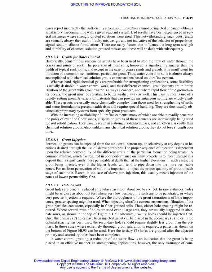
cases report incorrectly that sufficiently strong solutions either cannot be injected or cannot obtain asatisfactory hardening time with a given reactant system. Bad results have been experienced in sev-eral instances where strongly diluted solutions were used. This notwithstanding, such poor resultsare virtually always the result of faulty mix design, and not indicative of the behavior of properly de-signed sodium silicate formulations. There are many factors that influence the long-term strengthand durability of chemical solution grouted masses and these will be dealt with subsequently.
6B.6.3.3 Grouts for Water ControlHistorically, cementitious suspension grouts have been used to stop the flow of water through thecracks and joints of rock. The pore size of most soils, however, is significantly smaller than thewidth of typical rock joints, and except in the case of coarse sands and gravels, it is insufficient forintrusion of a common cementitious, particulate grout. Thus, water control in soils is almost alwaysaccomplished with chemical solution grouts or suspensions based on ultrafine cement.
Whereas hard, rigid chemical gels are preferable for strengthening applications, some flexibilityis usually desirable in water control work, and thus different chemical grout systems are in order.Dilution of the grout with groundwater is always a concern, and where rapid flow of the groundwa-ter occurs, the grout must be resistant to being washed away as well. This usually means use of arapidly setting grout. A variety of materials that can provide instantaneous setting are widely avail-able. These grouts are usually more chemically complex than those used for strengthening of soils,and some formulations present health risks and require special handling. They are thus usually ob-tained as proprietary systems from specialty grout producers.
With the increasing availability of ultrafine cements, many of which are able to readily penetratethe pores of even the finest sands, suspension grouts of these cements are increasingly being usedfor soil solidification. They usually result in a stronger solidified mass, and are often less costly thanchemical solution grouts. Also, unlike many chemical solution grouts, they do not lose strength overtime.
6B.6.3.4 Grout InjectionPermeation grouts can be injected from the top down, bottom up, or selectively at any depths or lo-cations desired, through the use of sleeve port pipes. The proper sequence of injection is dependentupon the relative permeability of the different strata of the particular formation being treated. Acommon mistake, which has resulted in poor performance on many projects, is to inject upstage in adeposit that is significantly more permeable at depth than at the higher elevations. In such cases, thegrout being injected, even at the higher levels, will tend to pipe down into the more permeablezones. For uniform permeation of soil, it is important to inject the proper quantity of grout in eachstage of each hole. Except in the case of sleeve port injection, this usually means injection of thezones of lowest permeability first.
6B.6.3.5 Hole LayoutGrout holes are generally placed at regular spacing of about two to six feet. In rare instances, holesmight be as close as about 0.5 feet where very low permeability soils are to be penetrated, or wherevery precise injection is required. Where the thoroughness of the grout saturation is of little impor-tance, greater spacing might be used. When injecting ultrafine cement suspensions, filtration of thegrout particles can occur, especially in finer-grained soils. Thus, closer hole spacing might be re-quired. Where several rows of holes are used over a large area, they are usually staggered in alter-nate rows, as shown in the top of Figure 6B.93. Alternate primary holes should be injected first.Once the primary (P) holes have been injected, grout can be placed in the secondary (S) holes. If theoptimal spacing has been used, the secondary holes should require slightly less grout than the pri-mary. In those cases where extremely thorough grout saturation is required, a pattern as shown onthe bottom of Figure 6B.93 can be used. Here the tertiary (T) holes are grouted after the adjacentprimary and secondary holes have been completed.
In water control grouting, a reduction of the water flow is an indication that the grout is beingplaced in an effective manner. In strengthening applications, however, the only assurance of com-
6.431GROUTING TO IMPROVE FOUNDATION SOIL
Downloaded from Digital Engineering Library @ McGraw-Hill (www.digitalengineeringlibrary.com)Copyright © 2004 The McGraw-Hill Companies. All rights reserved.
Any use is subject to the Terms of Use as given at the website.
GROUTING TO IMPROVE FOUNDATION SOIL
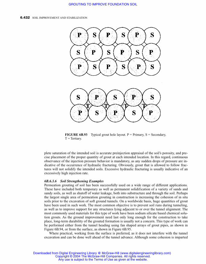
plete saturation of the intended soil is accurate preinjection appraisal of the soil’s porosity, and pre-cise placement of the proper quantity of grout at each intended location. In this regard, continuousobservance of the injection pressure behavior is mandatory, as any sudden drops of pressure are in-dicative of the occurrence of hydraulic fracturing. Obviously, grout that is allowed to follow frac-tures will not solidify the intended soils. Excessive hydraulic fracturing is usually indicative of anexcessively high injection rate.
6B.6.3.6 Soil Strengthening ExamplesPermeation grouting of soil has been successfully used on a wide range of different applications.These have included both temporary as well as permanent solidification of a variety of sands andsandy soils, as well as shutoff of water leakage, both into substructure and through the soil. Perhapsthe largest single area of permeation grouting in construction is increasing the cohesion of in situsoils prior to the excavation of soft ground tunnels. On a worldwide basis, huge quantities of grouthave been used in such work. The most common objective is to prevent soil runs during tunneling,as well as to improve support for any structures lying adjacent to or over the tunnel alignment. Themost commonly used materials for this type of work have been sodium silicate based chemical solu-tion grouts. As the ground improvement need last only long enough for the construction to takeplace, long-term durability of the grouted formation is usually not a concern. This type of work canbe performed either from the tunnel heading using fan shaped arrays of grout pipes, as shown inFigure 6B.94, or from the surface, as shown in Figure 6B.95.
Where practical, working from the surface is preferred, as it does not interfere with the tunnelexcavation and can be done well ahead of the tunnel advance. Although some cohesion is imparted
6.432 SOIL IMPROVEMENT AND STABILIZATION
FIGURE 6B.93 Typical grout hole layout. P = Primary, S = Secondary,T = Tertiary.
Downloaded from Digital Engineering Library @ McGraw-Hill (www.digitalengineeringlibrary.com)Copyright © 2004 The McGraw-Hill Companies. All rights reserved.
Any use is subject to the Terms of Use as given at the website.
GROUTING TO IMPROVE FOUNDATION SOIL

to the soil within hours of injection, substantial strength does not occur for a minimum of severaldays. Thus, a time lag is required between grout injection and tunnel excavation. In some instanceshowever, injection from the surface might not be possible, due to excessive tunnel depth or limita-tions of surface access. In such cases, where work must proceed from the tunnel heading, selectionof a grout system that rapidly gains strength is essential.
Permeation grouting for temporary support during construction has also been used on a wide va-riety of different types of excavation and structures. As part of the expansion of Los Angeles Inter-national Airport, it was necessary to underpin an existing concrete retaining wall, which was found-
6.433GROUTING TO IMPROVE FOUNDATION SOIL
FIGURE 6B.94 Grout holes in fan array.
FIGURE 6B.95 Grout holes from surface.
Downloaded from Digital Engineering Library @ McGraw-Hill (www.digitalengineeringlibrary.com)Copyright © 2004 The McGraw-Hill Companies. All rights reserved.
Any use is subject to the Terms of Use as given at the website.
GROUTING TO IMPROVE FOUNDATION SOIL

ed on wind-deposited fine dune sand. The wall was to be undermined and extended by a depth of 18feet. A sodium silicate based grout was injected from the top down using a special injection needle,which was advanced in one foot increments (Figure 6B.96). Two rows of holes, were used, as indi-cated on Figure 6B.97. The lower portion of the grouted mass was injected from a row of holes in-clined about 10 degrees from vertical, and the upper portion from holes inclined at about 20 de-grees. The quantities of grout injected at each level was adjusted so as to provide the required lateralsaturation needed, considering the inclination of the injection. The existing sands were improved toan unconfined compressive strength of about 150 psi. Excavation, which proceeded about twoweeks after the injection, required pneumatic tools, due to the strength of the mass.
The rehabilitation of a side-hill structure supporting a road required the excavation of an imme-diately adjacent vertical face. Because normal support was not possible, due to the existing down-slope, permeation grouting was performed to solidify the existing soil under the structure. In orderto make the shear vertical cut, it was necessary to actually remove a portion of the footings of thestructures supporting pillars, as can be observed in Figure 6B.98.
A sodium silicate based permeation grout was injected into the wind-deposited fine sand. Thiswas accomplished through a single row of grout holes 15 inches behind the face of the structure.The holes were spaced 30 inches apart. A quantity of grout that would solidify a theoretical 36 inchdiameter column based on the soil’s porosity was injected into each hole. Holes were injected on analternate primary/secondary split spacing order. Because the sand became less permeable withdepth, the grout injection pipes were driven to the final depth (Figure 6B.99) prior to injection,
6.434 SOIL IMPROVEMENT AND STABILIZATION
FIGURE 6B.96 Grout injection from the top down with special driveneedles.
Downloaded from Digital Engineering Library @ McGraw-Hill (www.digitalengineeringlibrary.com)Copyright © 2004 The McGraw-Hill Companies. All rights reserved.
Any use is subject to the Terms of Use as given at the website.
GROUTING TO IMPROVE FOUNDATION SOIL

6.435GROUTING TO IMPROVE FOUNDATION SOIL
FIGURE 6B.98 Solidified mass allowed excavation ofshear vertical cut, including removal of part of the sup-porting concrete footings.
FIGURE 6B.97 Two rows of inclined injectionprobes were used.
Downloaded from Digital Engineering Library @ McGraw-Hill (www.digitalengineeringlibrary.com)Copyright © 2004 The McGraw-Hill Companies. All rights reserved.
Any use is subject to the Terms of Use as given at the website.
GROUTING TO IMPROVE FOUNDATION SOIL

which was then made in one foot stages, from the bottom, up. As can be seen in Figure 6B.98, pneu-matic tools were required to trim back the solidified mass to the specified alignment. The flush cutwas 240 feet long and varied in height from 6 to 24 feet, as shown in Figure 6B.100. For those sec-tions which exceeded a cut height of 12 feet, a second row of holes was injected 27 inches behindthe cut face, so as to provide a stabilized wall approximately five feet thick.
The foundation for new equipment in a steel mill required excavating to within four feet of theshallow concrete pad foundation of a column, which supported a large traveling crane. In spite ofthe dynamic forces that would be transferred into the column during operation, the crane was re-quired to be in service 24 hours a day, seven days a week. The foundation was underlain with cohe-sionless sand and gravel, into which the required excavation would extend some 11 feet.
The entire area under the footing was solidified with a chemical solution grout, which wasinjected from the top down. This was done with hand-jetted, open-end ¾ inch pipe injectors (Fig-ure 6B.101). Injection probes were on a grid of 24 inches, and a quantity of grout sufficient tocreate an equivalent 30 inch column was placed. The nearly vertical excavation was then made(Figure 6B.102) with continual operation of the crane. Due to the dynamic forces exerted into thefooting by the passing crane, it was important to provide maximum possible stiffness, as well as
6.436 SOIL IMPROVEMENT AND STABILIZATION
FIGURE 6B.99 Special needles were driven to the depth ofinjection, which proceeded from the bottom, up.
Downloaded from Digital Engineering Library @ McGraw-Hill (www.digitalengineeringlibrary.com)Copyright © 2004 The McGraw-Hill Companies. All rights reserved.
Any use is subject to the Terms of Use as given at the website.
GROUTING TO IMPROVE FOUNDATION SOIL

6.437GROUTING TO IMPROVE FOUNDATION SOIL
FIGURE 6B.101 Grout injection in progress through standard ¾inch schedule 40 pipe.
FIGURE 6B.100 Vertical cut face varied from 6 feet to 24 feet high and extended for240 feet.
Downloaded from Digital Engineering Library @ McGraw-Hill (www.digitalengineeringlibrary.com)Copyright © 2004 The McGraw-Hill Companies. All rights reserved.
Any use is subject to the Terms of Use as given at the website.
GROUTING TO IMPROVE FOUNDATION SOIL
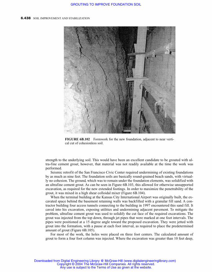
strength to the underlying soil. This would have been an excellent candidate to be grouted with ul-tra-fine cement grout; however, that material was not readily available at the time the work wasperformed.
Seismic retrofit of the San Francisco Civic Center required undermining of existing foundationsby as much as nine feet. The foundation soils are basically round-grained beach sands, with virtual-ly no cohesion. The ground, which was to remain under the foundation elements, was solidified withan ultrafine cement grout. As can be seen in Figure 6B.103, this allowed for otherwise unsupportedexcavation, as required for the new extended footings. In order to maximize the penetrability of thegrout, it was mixed in a high shear colloidal mixer (Figure 6B.104).
When the terminal building at the Kansas City International Airport was originally built, the ex-cavated space behind the basement retaining walls was backfilled with a granular fill sand. A con-tractor building four access tunnels connecting to the building in 1997 encountered this sand fill. Itcaved into his excavation, exposing utilities and undermining adjacent pavement. To mitigate theproblem, ultrafine cement grout was used to solidify the cut face of the required excavations. Thegrout was injected from the top down, through jet pipes that were marked at one foot intervals. Thepipes were positioned at a 15 degree angle toward the proposed excavation. They were jetted withgrout into the formation, with a pause at each foot interval, as required to place the predeterminedamount of grout (Figure 6B.105).
For most of the work, the holes were placed on three foot centers. The calculated amount ofgrout to form a four foot column was injected. Where the excavation was greater than 10 feet deep,
6.438 SOIL IMPROVEMENT AND STABILIZATION
FIGURE 6B.102 Formwork for the new foundation, adjacent to near verti-cal cut of cohesionless soil.
Downloaded from Digital Engineering Library @ McGraw-Hill (www.digitalengineeringlibrary.com)Copyright © 2004 The McGraw-Hill Companies. All rights reserved.
Any use is subject to the Terms of Use as given at the website.
GROUTING TO IMPROVE FOUNDATION SOIL

6.439GROUTING TO IMPROVE FOUNDATION SOIL
FIGURE 6B.104 Ultrafine cement grout was mixed in high-shear mixer. Note vortex in grout.
FIGURE 6B.103 Nine foot vertical cut under foundationin cohesionless beach sand.
Downloaded from Digital Engineering Library @ McGraw-Hill (www.digitalengineeringlibrary.com)Copyright © 2004 The McGraw-Hill Companies. All rights reserved.
Any use is subject to the Terms of Use as given at the website.
GROUTING TO IMPROVE FOUNDATION SOIL

a second row of holes was provided, split-spaced and three feet behind the initial row. The grout wascomposed of:
One bag Nittetsu Superfine cement
3.46 cubic feet (26 gallons) water
0.44 pounds high-range water reducer
It was mixed in a high-shear colloidal mixer and transferred into an agitator tank, which supplieda 2L8 Moyno pump. The pump was set for an injection rate of 2.6 cubic feet (20 gallons) of groutper minute.
Upon excavation, the sand fell freely from the injected columnar shaped masses (Figure6B.106). They withstood the elements, including several cycles of freeze and thaw, for a period ofseveral months. Both vibration and impact forces were created during demolition of the adjacentconcrete wall but had no apparent effect on the solidified mass.
To save time and money, NASA used permeation grouted piles rather than conventional pilingfor the foundation of a 350 ton missile launch gantry at Vandenberg Air Force Base in California. Atight schedule for launch of a Physics Interplanetary Monitoring Platform satellite into orbit re-quired very rapid construction of the launch facility. There simply was not sufficient time to con-struct conventional piling. Studies found the underlying soil to consist of about 20 feet (6.09 m) offine to medium dune sand, underlain by shale bedrock. Groundwater was present, at a depth ofabout 15 feet 4.57 m).
The gantry traveled on sets of rails mounted to two parallel pile caps. The heavily reinforcedconcrete caps were supported on two rows of piles, as shown in Figures 6B.107 and 6B.108. Thepile design was based on a permanent, chemically solidified mass, with an unconfined compressivestrength of at least 100 psi (689.5 kPa). This was considered conservative, as strengths nearly twicethat value were found to exist after seven years in a nearby installation, which used the same groutformulation. Accordingly, the 188 piles were designed, with a minimum diameter of 30 inches (0.76
6.440 SOIL IMPROVEMENT AND STABILIZATION
FIGURE 6B.105 Jetting grout into the sand backfill.
Downloaded from Digital Engineering Library @ McGraw-Hill (www.digitalengineeringlibrary.com)Copyright © 2004 The McGraw-Hill Companies. All rights reserved.
Any use is subject to the Terms of Use as given at the website.
GROUTING TO IMPROVE FOUNDATION SOIL

6.441GROUTING TO IMPROVE FOUNDATION SOIL
FIGURE 6B.106 Self-supporting solidified sands.
FIGURE 6B.107 Two rows of piles supported each parallel cap.
Downloaded from Digital Engineering Library @ McGraw-Hill (www.digitalengineeringlibrary.com)Copyright © 2004 The McGraw-Hill Companies. All rights reserved.
Any use is subject to the Terms of Use as given at the website.
GROUTING TO IMPROVE FOUNDATION SOIL

m). The diameter was increased to 60 inches (1.52 m) for the portion below the water table, aschemically grouted masses are known to obtain lower strengths under water. The piles extended fulldepth to the underlying shale formational deposit.
One distinct advantage of injected piles for the project was the ability to form them either beforeor after the pile cap had been cast. This greatly reduced the total time required for the work. Initial-ly, piles were injected prior to casting of one of the parallel concrete pile caps, while the other capwas being simultaneously constructed. Sleeves of 1½ inch (3.8 cm) pipe, as shown in Figure6B.108, were cast into the second cap at each pile location. The remaining piles were then injectedunder the completed pile cap, using the pipe sleeves for access.
A three-component, sodium silicate based chemical solution grout was prepared in batch mixingtanks (Figure 6B.109). The base tank combined sodium silicate, water, and a surfactant. The reac-tant tank combined ethyl acetate and calcium chloride reactants, with water. These were accuratelyproportioned by way of properly calibrated metering pumps, which fed a “flash mixer” located im-mediately ahead of the main grout pump. The flash mixer was simply a three inch squirrel cageblower enclosed in a small tank, turning at about 1800 rpm, so as to provide very high shear mixing.The final grout mixture contained 55% sodium silicate.
Injection was from the top down, through special drive needles (Figure 6B.110). The needles wereadvanced in one foot increments, followed by injection of the grout. A calculated amount of grout,sufficient to completely saturate a 36 inch column, was injected for the 30 inch sections, and 66 inch-es (1.67 m) for the 60 inch (1.52 m) sections. Tests carved from the solidified masses, both during thework and after completion, attained fundamental strengths somewhat greater than 200 psi.
A large, horizontal piston-type air compressor was installed on a massive reinforced concretefoundation. After several years of operation, excessive vibrations resulted, which not only affectedthe foundation block, but the surrounding building elements as well. Investigation revealed that the
6.442 SOIL IMPROVEMENT AND STABILIZATION
FIGURE 6B.108 Cross section of pile cap and solidified piles.
Downloaded from Digital Engineering Library @ McGraw-Hill (www.digitalengineeringlibrary.com)Copyright © 2004 The McGraw-Hill Companies. All rights reserved.
Any use is subject to the Terms of Use as given at the website.
GROUTING TO IMPROVE FOUNDATION SOIL

6.443GROUTING TO IMPROVE FOUNDATION SOIL
FIGURE 6B.109 Grout mixing and pumping plant.
FIGURE 6B.110 Special rig drives injection needles through pipe sleeves in the complet-ed pile cap.
Downloaded from Digital Engineering Library @ McGraw-Hill (www.digitalengineeringlibrary.com)Copyright © 2004 The McGraw-Hill Companies. All rights reserved.
Any use is subject to the Terms of Use as given at the website.
GROUTING TO IMPROVE FOUNDATION SOIL
foundation block was founded within a deposit of silty fine sand. The sand had a natural frequency,which was in harmony with that of the compressor. It was concluded that an increase of the stiffnessof the sandy soil was required to eliminate the excessive vibrations.
Accordingly, a grouting program was formulated with the intent of stiffening the sand throughsolidification with a chemical solution grout. The chosen formulation contained a 70% solution ofsodium silicate. The penetrability of a grout containing such a high concentration of the base com-ponent is significantly less than that of more conventional formulations; however, it was used forthis application, in order to provide the greatest degree of additional stiffness practicable. With agrout of such low penetrability, very slow pumping rates are necessary, and it is desirable to spacethe grout holes closely. The machine resulted in severe restrictions of space for the layout of groutholes. A single row was thus placed on 1.5 foot (.46 m) centers, immediately adjacent to and aroundthe periphery of the foundation (Figure 6B.111). Additional holes were placed within this boundarycontainment, as allowed by the existing conditions. The grout was injected at an unusually slow rateof less than one gallon per minute, as shown in Figure 6B.112.
Although the cost of injection at such low injection rates can be high, there are situations such asthis where they are warranted, and the resulting benefits are very cost effective. The grouting wascompletely successful, in that the excessive movements of the machine were completely eliminated.
6B.6.3.7 Permeation Grouting for Water ControlThe procedures used to create an impermeable barrier in soil are essentially the same as those usedto inject grout for strengthening applications. Whereas the grouted mass cannot be seen as in thosecases where the adjacent soil has been excavated, the degree to which the objectives have beenachieved will usually be obvious by way of reduction of the leakage. This is usually observed in the
6.444 SOIL IMPROVEMENT AND STABILIZATION
FIGURE 6B.111 The machine presented a severe restriction to holelocation and drilling.
Downloaded from Digital Engineering Library @ McGraw-Hill (www.digitalengineeringlibrary.com)Copyright © 2004 The McGraw-Hill Companies. All rights reserved.
Any use is subject to the Terms of Use as given at the website.
GROUTING TO IMPROVE FOUNDATION SOIL

drainage system, if existing, or from pump drawdown tests conducted in drainage holes placeddownstream of the curtain.
It is extremely difficult to effect an impermeable barrier with a single row of grout holes. Ac-cordingly, two or more rows of holes should be placed with split spacing, as illustrated in the top ofFigure 6B.93. Where an especially tight barrier is required, hole layout with tertiary injections, asshown on the bottom of Figure 6B.93, can be used. In such cases, a quantity of grout that exceedsthe theoretical quantity required should be placed, unless significantly high injection pressure ex-ists, which would indicate that all available voids have been filled.
Stoppage of water leakage adjacent to a solid object such as the wall of a structure is somewhateasier in that one boundary of the work is established. This can usually be accomplished with a sin-gle row of grout holes placed adjacent to the wall. An alternative would be to drill holes through thewall, on a regular spacing, followed by grout injection. Such work is best done during periods of ac-tive leakage, such that the effectiveness can be observed by way of a reduction of the leakage.
Water was penetrating the concrete masonry unit wall of a subsurface equipment room (Figure6B.113). A hydrophobic urethane grout was injected in a single line of holes, at 24 inch (0.6 m) in-tervals, and about six inches (15 cm) outside the wall. Injection was started in those areas that hadthe greatest leakage. As can be seen in Figure 6B.114, some of the grout penetrated the areas ofleakage, reacting on the wall surface. This gave confirmation that the culprit leakage paths were be-ing plugged, although it also created a nasty cleanup job.
In another instance, a seal around a pipe penetrating a concrete wall had failed, allowing water toleak into subsurface space (Figure 6B.115). A hydrophilic urethane grout was injected into a holeadjacent to the penetration, and extending to the back of the wall. As can be seen in Figure 6B.116,the grout, which was formulated to cure as a somewhat flexible foam in order to allow differential
6.445GROUTING TO IMPROVE FOUNDATION SOIL
FIGURE 6B.112 Grout injection rate was very slow due to low groutpenetrability.
Downloaded from Digital Engineering Library @ McGraw-Hill (www.digitalengineeringlibrary.com)Copyright © 2004 The McGraw-Hill Companies. All rights reserved.
Any use is subject to the Terms of Use as given at the website.
GROUTING TO IMPROVE FOUNDATION SOIL

6.446 SOIL IMPROVEMENT AND STABILIZATION
FIGURE 6B.113 Water leakage into equipment room.
FIGURE 6B.114 Reacted grout on wall.
Downloaded from Digital Engineering Library @ McGraw-Hill (www.digitalengineeringlibrary.com)Copyright © 2004 The McGraw-Hill Companies. All rights reserved.
Any use is subject to the Terms of Use as given at the website.
GROUTING TO IMPROVE FOUNDATION SOIL

movement, completely filled the annulus around the pipe. A small amount of grout also ran downthe wall, reacting thereon. Whereas such deposits of grout can be very hard to clean up, they do giveassurance that the leakage has been completely stopped.
Excessive water was flowing into a gallery of an embankment dam. The water was under a posi-tive head of about 300 feet (91.4 m) at the gallery level. Both hydrophobic and hydrophilic urethanegrouts were injected into the zone behind the leaks. Holes were drilled through the concrete section,packers installed, and the grout injected. Because the exact source of the leakage was uncertain,grout holes were angled in several different directions (Figure 6B.117). The injection was carefullymonitored, and grout returns, or diluted returns, carefully recorded. The leakage was reduced bymore than 95%, although some minor seepage continued. One advantage of grouting for water con-trol is that more holes can always be drilled and further grout injected until a satisfactory amount ofleakage reduction is achieved. As this work site was located far into the gallery, it is fortunate thatneither large equipment nor great quantities of material were required. Figure 6B.118 shows thesmall pneumatically powered proportioning pumps that were used.
6B.6.4 JET GROUTING
Jet grouting involves erosion of the soil with a high-pressure jet of grout, water, or air-enshroudedwater and the simultaneous injection of grout into the disturbed soil by means of a rotating drill
6.447GROUTING TO IMPROVE FOUNDATION SOIL
FIGURE 6B.115 Water leakage through defective pipeseal.
Downloaded from Digital Engineering Library @ McGraw-Hill (www.digitalengineeringlibrary.com)Copyright © 2004 The McGraw-Hill Companies. All rights reserved.
Any use is subject to the Terms of Use as given at the website.
GROUTING TO IMPROVE FOUNDATION SOIL

6.448 SOIL IMPROVEMENT AND STABILIZATION
FIGURE 6B.116 Leakage completely stopped.
FIGURE 6B.117 Grout holes at various angles so as to affect a large area of leakage potential.
Downloaded from Digital Engineering Library @ McGraw-Hill (www.digitalengineeringlibrary.com)Copyright © 2004 The McGraw-Hill Companies. All rights reserved.
Any use is subject to the Terms of Use as given at the website.
GROUTING TO IMPROVE FOUNDATION SOIL

stem and special jet monitor (Figure 6B.119). The drill stem and monitor are simultaneously raisedand rotated so as to mix the grout with a portion of the original soil to form soilcrete or, if required,it is possible to replace almost all of the soil with grout. By raising the drill stem absent any rotationit is possible to form soilcrete panels. The procedure has the advantage of effectiveness in virtuallyany type of soil, although the efficiency and thus strength of the resulting mass is soil-dependent. Itis lowest in clays and cohesive soils, and increases as the soil becomes more granular. Not surpris-ingly, the greatest strength is obtained in clean sands and gravels, which result in a concrete-likemass. Jet grouting can be used in the presence of large rocks or other obstructions, although a shad-ow effect can interrupt the continuity of the grout solidification.
In application, a hole, typically about 4 inches in diameter, must be accurately bored to the de-sired depth of improvement. The initial hole can be bored separately or by a drilling or jetting toolmounted onto the jet grouting monitor, which contains the nozzles. There are three major variationsof the jet grouting operation. In the simplest form, known as the one-fluid system, a special hollowdrill rod equipped with a monitor that contains horizontal jet nozzles at the tip (Figure 6B.120) islowered into the hole. A cement suspension grout is pumped down the drill rod at very high pressure(up to 9,000 psi) (52 kPa) while the drill rod and monitor are simultaneously rotated and withdrawn(Figure 6B.121). The grout, which exits the jet nozzles at high velocity, disintegrates the soil and
6.449GROUTING TO IMPROVE FOUNDATION SOIL
FIGURE 6B.118 Small pneumatically powered grout pump could be carried to injection location.
Downloaded from Digital Engineering Library @ McGraw-Hill (www.digitalengineeringlibrary.com)Copyright © 2004 The McGraw-Hill Companies. All rights reserved.
Any use is subject to the Terms of Use as given at the website.
GROUTING TO IMPROVE FOUNDATION SOIL

6.450 SOIL IMPROVEMENT AND STABILIZATION
FIGURE 6B.120 One-fluid jet grouting system.
FIGURE 6B.119 Jet grouting monitor ejects water and/or grout at highpressure.
Downloaded from Digital Engineering Library @ McGraw-Hill (www.digitalengineeringlibrary.com)Copyright © 2004 The McGraw-Hill Companies. All rights reserved.
Any use is subject to the Terms of Use as given at the website.
GROUTING TO IMPROVE FOUNDATION SOIL
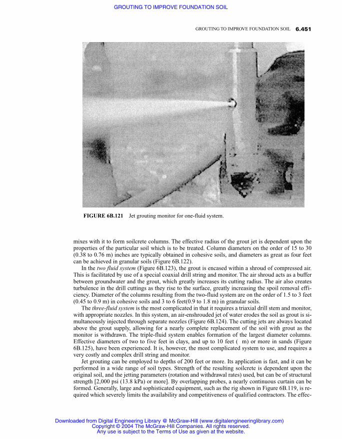
mixes with it to form soilcrete columns. The effective radius of the grout jet is dependent upon theproperties of the particular soil which is to be treated. Column diameters on the order of 15 to 30(0.38 to 0.76 m) inches are typically obtained in cohesive soils, and diameters as great as four feetcan be achieved in granular soils (Figure 6B.122).
In the two fluid system (Figure 6B.123), the grout is encased within a shroud of compressed air.This is facilitated by use of a special coaxial drill string and monitor. The air shroud acts as a bufferbetween groundwater and the grout, which greatly increases its cutting radius. The air also createsturbulence in the drill cuttings as they rise to the surface, greatly increasing the spoil removal effi-ciency. Diameter of the columns resulting from the two-fluid system are on the order of 1.5 to 3 feet(0.45 to 0.9 m) in cohesive soils and 3 to 6 feet(0.9 to 1.8 m) in granular soils.
The three-fluid system is the most complicated in that it requires a triaxial drill stem and monitor,with appropriate nozzles. In this system, an air-enshrouded jet of water erodes the soil as grout is si-multaneously injected through separate nozzles (Figure 6B.124). The cutting jets are always locatedabove the grout supply, allowing for a nearly complete replacement of the soil with grout as themonitor is withdrawn. The triple-fluid system enables formation of the largest diameter columns.Effective diameters of two to five feet in clays, and up to 10 feet ( m) or more in sands (Figure6B.125), have been experienced. It is, however, the most complicated system to use, and requires avery costly and complex drill string and monitor.
Jet grouting can be employed to depths of 200 feet or more. Its application is fast, and it can beperformed in a wide range of soil types. Strength of the resulting soilcrete is dependent upon theoriginal soil, and the jetting parameters (rotation and withdrawal rates) used, but can be of structuralstrength [2,000 psi (13.8 kPa) or more]. By overlapping probes, a nearly continuous curtain can beformed. Generally, large and sophisticated equipment, such as the rig shown in Figure 6B.119, is re-quired which severely limits the availability and competitiveness of qualified contractors. The effec-
6.451GROUTING TO IMPROVE FOUNDATION SOIL
FIGURE 6B.121 Jet grouting monitor for one-fluid system.
Downloaded from Digital Engineering Library @ McGraw-Hill (www.digitalengineeringlibrary.com)Copyright © 2004 The McGraw-Hill Companies. All rights reserved.
Any use is subject to the Terms of Use as given at the website.
GROUTING TO IMPROVE FOUNDATION SOIL

6.452 SOIL IMPROVEMENT AND STABILIZATION
FIGURE 6B.123 Two-fluid system where the groutis enshrouded in air.
FIGURE 6B.122 Solidified columns resulting from one-fluid system.
Downloaded from Digital Engineering Library @ McGraw-Hill (www.digitalengineeringlibrary.com)Copyright © 2004 The McGraw-Hill Companies. All rights reserved.
Any use is subject to the Terms of Use as given at the website.
GROUTING TO IMPROVE FOUNDATION SOIL

6.453GROUTING TO IMPROVE FOUNDATION SOIL
FIGURE 6B.124 Three-fluid system.
FIGURE 6B.125 Very large columns of soilcrete are possible with the three-fluid system.
Downloaded from Digital Engineering Library @ McGraw-Hill (www.digitalengineeringlibrary.com)Copyright © 2004 The McGraw-Hill Companies. All rights reserved.
Any use is subject to the Terms of Use as given at the website.
GROUTING TO IMPROVE FOUNDATION SOIL

tive diameter of the resulting mass is dependent on the individual system used, and the jetting andinjection parameters, such as grout pressure, rate of rotation, and withdrawal speed of the jet. Con-sidering these, and the influence of the particular site soil, trial injections are required to establishthe optimal hole spacing and operating parameters.
Perhaps the most significant limiting factor, however, is the production of large amounts of spoil,which must be contained, handled, and disposed of. Also, the very high pressures used at the jet canbe imparted into the soil at the nozzle depth if passage for the spoil should become blocked. This isa particular risk where the holes penetrate soft clays. Such high pressures could severely damage theadjacent soil and/or structures, and there are situations where the results could be catastrophic. Allthings considered, the practicability of the procedure is virtually limited to use in relatively large ap-plications. Details of the optimal procedures to be used will vary with individual project require-ments and the site soils. Consultation with available specialist contractors is thus advisable when theprocedure is contemplated.
6B.6.5 Replacement/Compensation/Fill Grouting
Grouting is often used to fill voids within the soil. These might be large subsurface voids in theground resulting from erosion, sinkhole activity, or solution cavities, or the result of old mine work-ings. Conversely, they might be small or thin planar voids resulting from leaking pipelines or similarevents, or voids resulting from subsurface construction or tunneling. Filling of thin planar voids ad-jacent to a hard surface such as concrete (Figure 6B.126), usually referred to as contact grouting orsometimes as backpack grouting if in connection with a tunnel (Figure 6B.127), is usually performedwith a cementitious fluid suspension or slurry grout. Any grout used to fill obvious voids should havea low water to cement ratio or be formulated to have little bleed or shrinkage. In this regard, defectsthicker than about an inch are best filled with very thick slurry or plastic consistency mortar grout.
6.454 SOIL IMPROVEMENT AND STABILIZATION
FIGURE 6B.126 Void under concrete foundation resulting from adjacent excavation.
Downloaded from Digital Engineering Library @ McGraw-Hill (www.digitalengineeringlibrary.com)Copyright © 2004 The McGraw-Hill Companies. All rights reserved.
Any use is subject to the Terms of Use as given at the website.
GROUTING TO IMPROVE FOUNDATION SOIL

Very large voids, those with a volume of more than about a cubic yard, are usually best filledwith commonly available concrete or mortar, utilizing ready-mixed material and standard concretepumps for placement (Figure 6B.128). Unlike in earlier times, modern cement and concrete tech-nology allow design of mixes with virtually any desired properties. As an example, otherwise com-mon mixes can be made to be very cohesive by inclusion of antiwashout admixtures. The settingtime can be accelerated to less than an hour, or delayed for up to several days.
For those applications where added weight is a concern, foaming agents can be introduced intothe mixer so as to provide low-density, hardened compositions. As the density of a cementitiouscomposition lowers, the strength will also be reduced. This is seldom a problem in geotechnicalgrouting, however, as strengths greater than that of the adjacent soil are seldom needed or justified.Typical density and strengths for readily available cellular concrete are on the order of 50 poundsper cubic foot (800 kg per m3) for an unconfined compressive strength on the order of 300 psi (2MPa), and 100 pounds per cubic foot (1600 kg per m3) for a strength of about 1500 psi (10.3 MPa).An area where low-density materials have been found particularly advantageous is grout filling ofthe annular space around pipes and liners in tunnels (Figure 6B.129). Not only is the cost of therather large amounts of material often used in such applications reduced, but also the risk of floatingof the liner is greatly reduced due to the lower density of the fill.
For the filling large voids, rapid injection rates are usually quite acceptable, and relatively littlepressure is normally required. Care must be taken however, to not develop too great a pressure whenthe defect is nearing complete filling. A rapidly increasing pressure will nearly always indicate this,as closure occurs. For this reason, pressure gages are required and must be monitored, as in all othergrouting.
Although it is possible to design ready-mixed compositions with low water to cement rations,and thus minimal shrinkage, more often than not, such mixes will be subject to shrinkage. This canbecome significant where the depth of such masses is great. Therefore, where the filling of suchlarge voids is to be complete and tight, injection of a fluid suspension or slurry contact grout can bemade after the main body has been filled. Where done, this should be delayed as long as possible,
6.455GROUTING TO IMPROVE FOUNDATION SOIL
FIGURE 6B.127 Typical void remaining afterconcreting of a tunnel lining.
Downloaded from Digital Engineering Library @ McGraw-Hill (www.digitalengineeringlibrary.com)Copyright © 2004 The McGraw-Hill Companies. All rights reserved.
Any use is subject to the Terms of Use as given at the website.
GROUTING TO IMPROVE FOUNDATION SOIL

6.456 SOIL IMPROVEMENT AND STABILIZATION
FIGURE 6B.128 Fill grouting of large voids with ready-mixed mortar and a standard concretepump.
FIGURE 6B.129 Low-density fill for the annular space around linings pro-vides economy as well as lessening the risk of floating the lining.
Downloaded from Digital Engineering Library @ McGraw-Hill (www.digitalengineeringlibrary.com)Copyright © 2004 The McGraw-Hill Companies. All rights reserved.
Any use is subject to the Terms of Use as given at the website.
GROUTING TO IMPROVE FOUNDATION SOIL

and at least several days, to allow primary shrinkage of the mass placement. In those situationswhere a strong grout is not wanted, it is possible to inject a low-mobility compaction-type groutwith a very low cement content or even completely absent of cement; however, this will be muchmore expensive than simply filling with ready-mixed material.
6B.6.6 Groutjacking
It has long been recognized that settled pavements could be accurately raised by slab jacking, whichis simply the controlled injection of grout under them. (Refer also to Section 7B.2.) If a void existsunder the slab, which allows the grout to immediately spread, no further preparation is required. Ifsuch is not the case, a void can be created by jetting through the grout holes with water or com-pressed air (Committee on Grouting, 1977). The same principal is involved when groutjacking astructure, except that the void must extend over a larger area, due to the higher loads involved. Thearea of void required is a function of the weight of the structure to be jacked times the availablegrout pressure, and must include provision for any frictional resistance between the structure andthe adjacent soil. Thus, for heavy structures, considerable pressure and area is needed. Such liftinghas sometimes been facilitated by horizontal boring or hand mining under the structure. Whereaslight pavements can be raised with a wide variety of grout materials and only nominal pressure[generally less than 100 psi (690 kPa)], once lift has been initiated, very low mobility grouts such asthose used for compaction grouting and generally much higher pressures (500 to 2,000 psi) (3.4 to13.8 MPa) are required under heavy structures.
If compaction grouting is being used to improve the soils under a structure, it is possible to lift itduring the grout injection. If sufficient lift has not been obtained during the compaction, however,or perhaps the underlying soils are not in need of improvement, it is possible to jack a structure bycreating a controlled, horizontal hydraulic fracture in the soil. The fracture is then expanded orjacked until the desired lift occurs. Uncontrolled hydraulic fractures that occur during grouting, usu-ally follow the orientation of the minor principal stress of the soil, which is normally a verticalplane. A horizontal fracture can usually be created, however, by injecting a small amount (3 to 5 gal-lons) of a highly mobile grout into a casing that extends to within about one inch of the bottom ofthe hole. A low-mobility grout, such as that used for compaction grouting, can then be injected so asto open the fracture and raise the ground and overlying structure. Raising of both pavements andstructures to very close tolerances is possible. Although many grouting contractors lack the knowl-edge and ability for this type of work, those who are qualified will routinely raise a structure towithin about 0.1 of an inch of the specified elevation.
One side of an aluminum smelter, which was in full operation and filled with molten metal, hadsettled several inches. The differential settlement resulted in fracture of some of the steel framing el-ement connections, which restrained the firebrick lining (Figure 6B.130). The very high heat in thefurnace area made investigation of the problem or remedial work extremely difficult. However, be-cause the owner had a commitment for delivery of a highly specialized alloy, several months of fur-ther operation were required, and something had to be done to temporarily relieve the distress of thesteel containment structure.
Grout holes inclined about 60 degrees off of vertical were drilled under the settled side. Theywere fully cased to the edge of the shallow foundation elements, and extended about another eightfeet under the base. About one cubic foot of slurry-consistency grout was injected into the holes,followed by low-mobility grout, such as would be used for compaction grouting. Although, theobjectives of the work were to raise the settled portion of the structure only, and no compaction ofthe underlying soils was intended, an unexpectedly high grout take revealed that the silty soils im-mediately under the foundation were quite loose. Although the intent of the groutjacking was lim-ited to raising the settled portion of the foundation about one inch, in order to temporarily relievethe structural distress, the foundations were raised nearly four inches (20.1 cm) to near their orig-inal level.
Based on the grout takes and the history of the site, it was suspected that localized soil distur-
6.457GROUTING TO IMPROVE FOUNDATION SOIL
Downloaded from Digital Engineering Library @ McGraw-Hill (www.digitalengineeringlibrary.com)Copyright © 2004 The McGraw-Hill Companies. All rights reserved.
Any use is subject to the Terms of Use as given at the website.
GROUTING TO IMPROVE FOUNDATION SOIL

bance resulted when a drainage sump was removed from the area prior to construction of the fur-nace. As no further settlement occurred over the next several months, the originally contemplatedinvestigation and permanent remedial program were cancelled.
Work on a new parking structure in Texas had to be stopped due to differential settlement of thepile-supported foundation. Groutjacking was used to precisely raise the individual settled columnsand their supporting piles (Figure 6B.131). A two inch (5 cm) ID casing, such as that commonlyused for compaction grouting, was placed to slightly past the pile tip elevation. A five gallon bucketof cementitious slurry was dumped into the casing, immediately followed by a compaction groutmix that incorporated the preferred aggregate gradation shown in Figure 6B.57. The columns wereall raised to within about 1/16 th of an inch (1.5 mm) of their original elevation.
6B.7 SPECIAL CONSTRUCTION TECHNIQUES INVOLVING GROUTING
There are a number of specialized foundation construction methods that involve grouting of onesort or another. The development of such systems has advanced rapidly within the last several years.This has been greatly facilitated by the ready availability of both high-capacity cranes and modernconcrete and mortar pumps, as well as significant advances in cement and concrete technology.
6B.7.1 Auger-Cast Piles
In the late 1940s, the Intrusion-Prepakt Company began experimenting with novel pile installationmethods. An early result was the auger-cast pile. Therein, a hollow-stem, continuous-flight auger ofthe pile design diameter (Figure 6B.132), is drilled into the soil to the intended pile tip elevation. A
6.458 SOIL IMPROVEMENT AND STABILIZATION
FIGURE 6B.130 Metal furnace full of molten aluminum during groutjacking.
Downloaded from Digital Engineering Library @ McGraw-Hill (www.digitalengineeringlibrary.com)Copyright © 2004 The McGraw-Hill Companies. All rights reserved.
Any use is subject to the Terms of Use as given at the website.
GROUTING TO IMPROVE FOUNDATION SOIL

cementitious grout or mortar is then injected as the auger is withdrawn. The injection pressure of thegrout can actually aid in the withdrawal of the soil-laden auger, and contributes significantly to therealized skin friction. As originally conceived, equipment limitations controlled the size of piles thatcould be practically constructed, and thus their capacity.
With the advent of the modern concrete pump in the 1960s, it became practicable to rapidly in-ject high-strength mortar or small-aggregate concrete, rather than the original particulate grout. Thisallowed virtually complete filling of the hole with the higher strength replacement material, whichgreatly widened the obtainable pile capacities and the range of soil for which the technique is suit-able. This period also saw significant advancements in hydraulic power transmission technology,which made possible very high torque drilling machines and high-capacity cranes and carriages onwhich to mount them.
With presently available equipment and technology, auger-cast piles can be installed in virtuallyany granular soil that is relatively free of large rocks or boulders. Piles with diameters up to 36 inch-es and lengths on the order of 130 feet (39 m) have been constructed. They are routinely placed towithstand a design load of 200 tons, (182 metric ton) or more. The auger-cast method can be used toconstruct individual piles, including batter piles, or any combination or groups. In fact, the methodhas been used extensively to install secant piles so as to form a continuous wall for earth retention(Figure 6B.133). The technology for auger-cast piles is now well developed and several specialtycontractors regularly install them. The Deep Foundations Institute (1993) has available a reference,Augered Cast-in Place Piles Manual, which discusses the process in detail and includes a guidelinespecification.
6.459GROUTING TO IMPROVE FOUNDATION SOIL
FIGURE 6B.131 Groutjacking was used to precisely level pile-supported columns of parking structure.
Downloaded from Digital Engineering Library @ McGraw-Hill (www.digitalengineeringlibrary.com)Copyright © 2004 The McGraw-Hill Companies. All rights reserved.
Any use is subject to the Terms of Use as given at the website.
GROUTING TO IMPROVE FOUNDATION SOIL

6B.7.2 Mixed-in-Place Piles
Mixed-in-place piles involve rotating a hollow drill stem into the ground to the proposed pile tip el-evation. The stem is equipped with suitable outlet nozzles and mixing blades of the desired pile di-ameter. A cementitious suspension grout is pumped down the hollow stem while it is slowly insert-ed and simultaneously rotated so as to initially blend the grout into the in situ soil. Rotationcontinues as the apparatus is slowly withdrawn from the hole, further mixing so as to enhance theinitial blending. As originally conceived in the early 1950s, the finished pile would be composed ofa mixture of the native material with a cement suspension grout. The piles can be formed in a rangeof soil materials, as long as they are not very stiff or very dense and are free of large rocks or boul-ders. Strength of the resulting piles is dependent on the amount of grout blended and the gradationof the in situ soil.
In essentially clean sands that are reasonably free of silt or clay fines, strengths similar to thoseof conventional mortars are routinely obtained. As the amount of fines increases, however, the re-sulting strength levels decrease. Auger-cast piles have many advantages. They can be installedquickly, and the installation is relatively free of noise and vibration. Because the hole is alwaysfilled with either soil or the finished pile, neither groundwater nor caving soil is a problem. Mixed-in-place-piles were developed by the Intrusion-Prepakt Company in the early 1950s and were theforerunner of the much larger-scale process now known as DMS (deep soil mixing). Traditionalmixed-in-place-piles were commonly 16 inches in diameter with depths up to about 50 feet (15 m).Because of the method of formation, they provide a very tight and irregular interface with the sur-rounding soil, and capacities are thus often greater than equivalent driven piles.
6.460 SOIL IMPROVEMENT AND STABILIZATION
FIGURE 6B.132 Casting of an auger-cast pile.
Downloaded from Digital Engineering Library @ McGraw-Hill (www.digitalengineeringlibrary.com)Copyright © 2004 The McGraw-Hill Companies. All rights reserved.
Any use is subject to the Terms of Use as given at the website.
GROUTING TO IMPROVE FOUNDATION SOIL
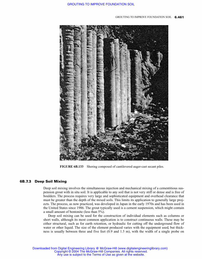
6B.7.3 Deep Soil Mixing
Deep soil mixing involves the simultaneous injection and mechanical mixing of a cementitious sus-pension grout with in situ soil. It is applicable to any soil that is not very stiff or dense and is free ofboulders. The process requires very large and sophisticated equipment and overhead clearance thatmust be greater than the depth of the mixed soils. This limits its application to generally large proj-ects. The process, as now practiced, was developed in Japan in the early 1970s and has been used inthe United States since 1986. The grout typically used is a cement suspension, which might containa small amount of bentonite (less than 5%).
Deep soil mixing can be used for the construction of individual elements such as columns orshort walls, although its most common application is to construct continuous walls. These may beeither structural, such as for earth retention, or hydraulic for cutting off the underground flow ofwater or other liquid. The size of the element produced varies with the equipment used, but thick-ness is usually between three and five feet (0.9 and 1.5 m), with the width of a single probe on
6.461GROUTING TO IMPROVE FOUNDATION SOIL
FIGURE 6B.133 Shoring composed of cantilevered auger-cast secant piles.
Downloaded from Digital Engineering Library @ McGraw-Hill (www.digitalengineeringlibrary.com)Copyright © 2004 The McGraw-Hill Companies. All rights reserved.
Any use is subject to the Terms of Use as given at the website.
GROUTING TO IMPROVE FOUNDATION SOIL

the order of three times the thickness. Common depth limits are on the order of 100 to 150 feet(30 to 45 m), although more than 200 feet (60 m) have been produced. The process is highlymechanized and employment of high-capacity, fully automated grout plants is common. It is thusperformed only by a limited number of specialty contractors, most of which have their own pro-prietary equipment and methodology.
6B.7.4 Micropiles
Micropiles are formed by drilling of the pile hole, usually with simultaneous placement of a stay-in-place casing. Structurally, they are thus a composite of the casing and a grout fill. They are typicallydesigned as friction piles, and their intimate contact with the surrounding soil is thus critical. Mi-cropiles are of relative small diameter, usually less than 10 inches (25 cm), and have been placed todepths of about 200 feet (30 m), although more typical depths are on the order of 100 feet (60 m) orless. The casing is usually composed of appropriate lengths of threaded flush wall sections. In orderto accommodate the flush threaded joint and the structural requirements of the particular design,fairly thick casing walls are typical. Additional reinforcement can be embedded into the grout fillbefore it hardens, if required.
Once the pile is drilled to depth, a cementitious grout is injected, oftentimes through the drill rigmud swivel. Although cement suspension grouts are the most often used, ready-mixed mortars havealso been employed. Typically, the drill bit is of greater diameter than the outside diameter of thecasing, resulting in an annular space, which must be filled with grout, so as to provide the intimatecontact with the soil required of a friction pile. The grout is usually injected into the casing, with in-jection continuing until it has returned up the annulus to the surface. The casing is nearly alwayscustom fabricated, and can be of any length, which allows the piles to be placed in areas of restrict-ed headroom. Figure 6B.134 shows an installation of closely spaced, 200 foot deep micropiles in anarea of restricted access. Because of the requirement of special equipment and skills, micropiles aregenerally constructed by a limited number of specialty contractors, many of whom have their ownproprietary systems. The work is often performed on a design–build basis, with performance loadtesting of the design pile capacity the primary acceptance requirement.
6B.7.5 Posttensioned Soil Anchors
The pullout capacity of soil anchors can be greatly enhanced by injection of grout in the anchoragezone. This is the result of both the increased intimacy at the anchor–soil interface and, often, an im-proved soil in the anchorage zone. Although cement suspension grout is most commonly used,chemical permeation grouting has been employed in sandy soils. The grout is usually injected to thetip of the anchor, either through a separate injection tube or the anchor itself, in the case of hollowstem anchors. Construction of ground anchors is somewhat specialized, and grouting in connectiontherewith is usually performed by the anchor contractor.
6B.8 INJECTION FUNDAMENTALS
Regardless of the type of grout being used or the purpose of its injection, there are several importantparameters that will always be present and must be considered. A good understanding of these fac-tors and their relationships are thus fundamental to proper design or field performance of any grout-ing program. The pore pressure of the soil into which grout is being injected comes under increasedpressure and, oftentimes, the soil is subjected to mechanical disruption as the grout is introduced. Itis important to understand these factors, and to make prompt adjustments in the injection parame-ters as required, if excessive disruption or damage is to be precluded.
6.462 SOIL IMPROVEMENT AND STABILIZATION
Downloaded from Digital Engineering Library @ McGraw-Hill (www.digitalengineeringlibrary.com)Copyright © 2004 The McGraw-Hill Companies. All rights reserved.
Any use is subject to the Terms of Use as given at the website.
GROUTING TO IMPROVE FOUNDATION SOIL

Except in those cases where continuous monitoring of previously installed geotechnical instru-mentation occurs, the only parameter that provides timely information is the injection pressure, andmore particularly, its behavior during injection. Although a given pressure level in itself is of littlevalue, knowledge of the pressure variations at a constant pumping rate usually reveal much valuableinformation as to the constantly changing conditions in the soil at the point of injection. The pres-sure is directly effected by both the grout rheology and the pumping rate. Whereas changing thegrout rheology during injection usually requires a time delay, adjusting the injection rate can bedone instantly, providing proper equipment is being used. Continuous observation of the grout pres-sure behavior and its control through appropriate variation of the pumping rate is necessary if opti-mal effectiveness of the grout injection is to be realized.
6B.8.1 Injection Pressure
Setting of the maximum injection pressure is perhaps one of the most contentious issues in geotech-nical grouting, especially in the United States. A widely recognized rule of thumb says that the max-imum pressure in psi should be limited to twice the injection depth in feet. Well-documented experi-ence, in the United States as well as abroad, however, has proven this idea to be faulty. Thedeveloped pressure is directly proportional to the rate of injection. For reasons of economics, use ofthe highest safe injection rate, and thus highest pressure, is desirable. This pressure level will be
6.463GROUTING TO IMPROVE FOUNDATION SOIL
FIGURE 6B.134 Construction of micropiles in an area of restricted access.
Downloaded from Digital Engineering Library @ McGraw-Hill (www.digitalengineeringlibrary.com)Copyright © 2004 The McGraw-Hill Companies. All rights reserved.
Any use is subject to the Terms of Use as given at the website.
GROUTING TO IMPROVE FOUNDATION SOIL

variable and is dependent upon many factors, including the type and rheology of the grout beingused, the purpose of the injection, particulars of the site soil, hole geometry, etc.
The pressure used in grouting can be divided into two distinct modes: that which results fromfriction and any restriction within the delivery system (pump output to lower end of casing), and thatwhich results from resistance to permeation or displacement of the formation or other medium be-ing filled. Where injection is through a void of uniform cross section, such as a pipe or injectionhose, the total pumping pressure will be dependent upon the length thereof, and will be the productof the unit length resistance times the number of units of length. Unless a void is filled with water orisolated such that air cannot escape, pressure at the leading edge of the grout will always be zero.Where injection is made into a porous mass such as soil, or voids of varying size and configuration,the pressure distribution within the grout mass will be ever variable. It will, however, always begreatest at the point of injection, which is typically the lower end of the injection casing, and willdecrease with distance therefrom.
Because the effective pressure on the formation will invariably start at the casing outlet, it is im-portant to consider the pressure differential between that point and the top of the casing, where pres-sure readings are typically observed. This value may be either positive or negative, depending uponthe particulars of both the grout and the delivery system. As an example, on a recent compactiongrouting project, the contractor proposed use of a six inch (150 mm) diameter injection casing forsome very deep holes. Because of concern that the static head pressure might be excessive, a trialinjection using the six inch casing was made. A positive grout pressure of 0.45 psi (0.3 kPa) per ver-tical foot (0.33 m) of casing resulted. Because the total gravity pressure that would result at the bot-tom of the hole would be excessive, a smaller three inch (75 mm) casing was required for the pro-duction work. This resulted in a head loss of about 0.45 psi (0.3 kPa) per vertical foot.
With the above in mind, it is possible, through experimentation and calculation, to determine theapproximate pressure differential between the pressure gauge at the point of injection and the casingoutlet, where the grout makes first contact with the formation. The term approximate is used be-cause some variation will occur within a delivery line, depending upon the smoothness of its interi-or, number and sharpness of bends, and any restrictions at couplings or other fittings. Because it isthe pressure at the bottom of the injection casing that is pertinent, the gauges for pressure evaluationshould always be located as close as possible to the point of grout entrance into the formation, andthe injection pressure corrected for any loss or gain.
Many factors contribute to the total pump pressure required for injection. Major contributors tothat pressure are frictional resistance within the delivery system, rheology of the grout beingpumped, rate of pumping, size of the lines and resulting grout velocity, and frictional resistance atthe grout conduit wall interface, which is a function of the wall smoothness and its affinity for theparticular grout being used. Once the grout is in the medium to be filled, both the size of the indi-vidual fractures or pores and their surface condition are major factors. Obviously, the rheology ofthe grout and its affinity for the formation surfaces are also significant contributors.
6B.8.2 Pumping Rate
As aforementioned, the pumping rate and developed pressure are directly related. An increase inpumping rate will always result in an increase in pressure, as will a reduction result in lower pres-sure. This is well illustrated in Figure 6B.135, which is an actual printout of a computer-generatedrecord of pressure behavior on a recent project where the grout pump malfunctioned. The pistonspeed varied such that one piston was traveling nearly twice as rapidly as the other. The actual pumpstrokes can be observed by their pressure differentials, and it will be noted that the pressure on theshort stroke (higher pumping rate) was more than 100 psi greater than that on the slower longstroke. In this figure, it is also of note that the pressure raised slightly during each of the shortstrokes, which is indicative of a generally optimal pumping rate, whereas there was a slight pressuredecay during the long strokes, which indicates a slower than optimal rate.
Because the resistance developed within the formation to be treated is beyond our control, the in-
6.464 SOIL IMPROVEMENT AND STABILIZATION
Downloaded from Digital Engineering Library @ McGraw-Hill (www.digitalengineeringlibrary.com)Copyright © 2004 The McGraw-Hill Companies. All rights reserved.
Any use is subject to the Terms of Use as given at the website.
GROUTING TO IMPROVE FOUNDATION SOIL

jection rate selected must be limited, such that excessive pressure will not be developed. Becausewide variation of formation resistance is common, flexibility of the output capacity of the pump isusually required. This is no doubt the reason for the past widespread use of circulating grout injec-tion systems. In such systems, the grout is continuously circulated in a route from the pump, pastthe grout hole, and back to the pump, as shown on Figure 6B.136. A connection to the grout hole ismade with a “T” fitting in the line. A valve is located on the return side of the “T” fitting and a valveand pressure gauge are located between the “T” fitting and the injection hole casing, as illustrated inFigure 6B.137. The amount of grout that is allowed to go into the hole, and thus the injection rate,can be varied by “throttling” the valves. Because economy dictates use of the highest practical in-jection rate, the valves are adjusted so as to allow the maximum amount of flow possible, withoutexceeding the maximum allowable pressure.
Single-line direct delivery systems, wherein the grout flow is directly from the pump to the grouthole (Figure 6B.138), should be used only with variable output pumps. Therein, the speed of thepump, and thus the rate of the grout output, is regulated so as to maintain injection rates that will notexceed the allowable pressure. Varying the rate in discrete increments provides the advantage of ob-servation of even slight changes of pressure, facilitating optimum evaluation of the grout movementwithin the formation.
Grout pumps and delivery systems should be sized for reasonable injection rates, so as to pre-clude the development of excessive pressures during injection. All other things being equal, systempressures will usually diminish as the pipe or hose size increases. The size should not be so large,however, as to preclude complete emptying of the system within a reasonable time. In this regard,the set time of the grout must be considered so that it is not allowed to react within the system.Many grout materials, and especially cementitious mixes, will tend to build up on the wall of the de-livery system if sufficient grout velocity is not maintained. Such build-up results in an ever decreas-ing opening for the grout to travel, and will thus increase both the grout velocity and resulting pres-sure. Figure 6B.139 delineates the velocity of grout through various size delivery lines.
The importance of the relationship of injection pressure to pumping rate cannot be overempha-
6.465GROUTING TO IMPROVE FOUNDATION SOIL
FIGURE 6B.135 Computer-generated printout showing variation of pressure concurrent with changes inpumping rate.
Downloaded from Digital Engineering Library @ McGraw-Hill (www.digitalengineeringlibrary.com)Copyright © 2004 The McGraw-Hill Companies. All rights reserved.
Any use is subject to the Terms of Use as given at the website.
GROUTING TO IMPROVE FOUNDATION SOIL

6.466 SOIL IMPROVEMENT AND STABILIZATION
FIGURE 6B.137 Valves are manipulated to maintain proper pressure.
FIGURE 6B.136 Circulating injection system with grout return to the agitator.
Downloaded from Digital Engineering Library @ McGraw-Hill (www.digitalengineeringlibrary.com)Copyright © 2004 The McGraw-Hill Companies. All rights reserved.
Any use is subject to the Terms of Use as given at the website.
GROUTING TO IMPROVE FOUNDATION SOIL

6.467GROUTING TO IMPROVE FOUNDATION SOIL
FIGURE 6B.138 Direct injection system where grout flows fromthe pump directly to the grout hole collar.
FIGURE 6B.139 Velocity of grout through various sized delivery lines.
Downloaded from Digital Engineering Library @ McGraw-Hill (www.digitalengineeringlibrary.com)Copyright © 2004 The McGraw-Hill Companies. All rights reserved.
Any use is subject to the Terms of Use as given at the website.
GROUTING TO IMPROVE FOUNDATION SOIL

sized. Many practitioners seem to fall under the erroneous impression that the maximum grout pres-sure level alone indicates the degree of soil improvement obtained. In many cases of investigatingthe cause of grouting program failures, the writer has found records that indicated only the holenumber, grouting depth, and maximum pressure reached during injection. Such records are usuallyshort of useless for obtaining an understanding of what actually happened in the ground, and thusthe cause of the failure. The pumping rate/pressure relationship is so important that it warrants spe-cial attention. The specifying or recording of injection pressure is of absolutely no use unless the in-jection rate at which the pressure level occurred is also specified and/or recorded.
6B.8.3 Pressure Behavior
A basic law of physics tells us that an increase in pressure always indicates greater resistance toflow, whereas a reduction indicates less resistance. Although somewhat subjective, knowing the val-ue and nature of the pressure movement allows one with experience to make an informed predictionas to the cause. As an example, if we were to assume that a pressure of 100 psi (700 kPa) was re-quired to pump a grout material through a given length of hose, should a connection located in themiddle of the length become broken, the pressure would sharply drop to approximately half of itsoriginal value. Similarly, were a restriction placed on its outlet end, a sudden increase in pressurewould result. Applying this theory to the real world of grout injection, it is widely recognized that asudden reduction in pressure indicates a likely disruption, in the interior of the soil or rock mass be-ing grouted (Houlsby, 1990), (Warner and Brown, 1974).
Within the writer’s experience, sudden changes in pressure, or increases of injection rate at aconstant pressure, always indicate the occurrence of a significant event. In more cases than not,such events lead to negative results, which can be greatly minimized, and in many cases completelyaverted, through quick response, usually the immediate lowering of the pumping rate or completecessation of injection.
Typical events that are accompanied by a loss of pressure include hydraulic fracturing of the soil;displacement or heaving of the formation; grout loss into a subsurface pipe or other substructure;outward displacement of a downslope or retaining wall; grout entering a much larger fracture orvoid, or encountering a much softer or more permeable formation; thinning of the grout or otherchange in the grout rheology, which increases its mobility; leakage of the grout; or pump malfunc-tion.
An interesting example was observed during the injection of a very deep compaction groutinghole. A sudden drop in pressure was noted. Consideration of the value of the pressure drop, com-bined with the depth of injection and the injection rate, ruled out hydraulic fracturing of the forma-tion as the cause. The particular circumstances of the injection led to the conclusion that some sortof break in the injection line was the most plausible source of the sudden pressure loss. The writerassumed that a casing joint at a fairly shallow depth had failed. After withdrawal of forty feet of cas-ing, however, a vertical split, as shown in Figure 6B.140, was found. Whereas there were no under-ground pipes in the area of the injection, if such had existed, the indicated pressure behavior couldhave indicated leakage of the grout therein. The importance of meticulous monitoring of the injec-tion behavior cannot be overemphasized.
Events that are preceded by an increase in pressure include plugging or restriction in the injec-tion system or formation, thickening or lowering the mobility of the grout, completion of the fillingof a fracture or void, or binding or wedging of a structure or slab that is being raised, (Committee onGrouting, 1977)
The compaction grouting procedure employs relatively high pressures, even at shallow depths.This results in relatively large pressure variations that are especially instructive. Significant pressuremovements develop during injection, as conditions within the zone of influence of the growinggrout mass change. Where the defective soil is of a uniform though inadequate condition, such as inthe case of very loose wind-deposited granular materials, the pressure buildup will generally beconstant, as illustrated in Figure 6B.141.
6.468 SOIL IMPROVEMENT AND STABILIZATION
Downloaded from Digital Engineering Library @ McGraw-Hill (www.digitalengineeringlibrary.com)Copyright © 2004 The McGraw-Hill Companies. All rights reserved.
Any use is subject to the Terms of Use as given at the website.
GROUTING TO IMPROVE FOUNDATION SOIL

6.469GROUTING TO IMPROVE FOUNDATION SOIL
FIGURE 6B.140 Split of casing that resulted in sudden drop of injection pressure.
FIGURE 6B.141 Steady pressure buildup indicates generally uniformsoil.
Downloaded from Digital Engineering Library @ McGraw-Hill (www.digitalengineeringlibrary.com)Copyright © 2004 The McGraw-Hill Companies. All rights reserved.
Any use is subject to the Terms of Use as given at the website.
GROUTING TO IMPROVE FOUNDATION SOIL

Often times, however, settlement problems develop as a result of defects such as masses ofburied brush or large boulders in or under a fill, uncompacted soil resulting from initial clearing ordevelopment of haul roads, or insufficient removal of slopewash or other weak surface materialsprior to fill placement. Both the existence and approximate volume of such subsurface defects canbe determined through continuous pressure behavior monitoring. In such cases, a nonuniform pres-sure buildup will be experienced (Figure 5.B.142). In the figure, the approximate volume of the ap-parent defect can be ascertained by determining the amount of grout that was injected from the timeof the initial pressure drop until the previous pressure level is regained.
As soil grouting is frequently performed under or in close proximity to existing structures, un-derground piping and other substructure are often nearby. There is thus inherent with the procedurealways a risk of grout leakage into such utilities. The occurrence of grout entering substructures willnearly always be preceded by a significant drop of the injection pressure. Whereas such drops com-monly indicate other events, in cases where grout has entered an underground pipe a slow but steadyincrease of the initial entrance pressure will typically occur. In such cases, the level and behavior ofthe pressure will usually be markedly different from that which was experienced prior to the occur-rence of leakage, signaling the need for corrective action.
Whereas major events can be detected by substantial pressure movements or changes of injec-tion rate, more subtle events often result in only minor changes. Such minor changes cannot easilybe observed in circulating injection systems or those systems that are subject to pulsations frompump stroking. Thus, where detection of minor events is important, use of a constant output pump,free of any significant pulsation, combined with careful and continuous pressure monitoring is rec-ommended. Piston pumps operating at rates greater than about one hundred strokes per minute,combined with a minimum hose length of about 100 feet (33 m), have been found satisfactory, as athigh rates the stroking results only in a flutter of the gauge needle, and dampening occurs in theflexible hose. Pressure pulsations resulting from stroking of piston or diaphragm type pumps can
6.470 SOIL IMPROVEMENT AND STABILIZATION
FIGURE 6B.142 Erratic pressure buildup indicates subsurface voids.
Downloaded from Digital Engineering Library @ McGraw-Hill (www.digitalengineeringlibrary.com)Copyright © 2004 The McGraw-Hill Companies. All rights reserved.
Any use is subject to the Terms of Use as given at the website.
GROUTING TO IMPROVE FOUNDATION SOIL

also be lessened through use of a hydraulic accumulator near the pump outlet and/or an increase ofat least 50% in the diameter of the injection hose for a distance of about 25 feet (7 m), starting at thepump outlet. Conversely, as illustrated in Figure 6B.135, the actual pressure of individual pumpstrokes can be observed in the case of piston pumps operating at very slow stroke rates.
Pressure behavior can be obtained through continuous readings of a pressure gauge and manualentries onto an appropriate form, or with fully automated equipment employing either a continuousdisk or strip chart recorder, or with computer processing. Regardless of the recording method, theactual time of each entry should be included, and when feasible, continuous real time should be in-cluded in the record. When manual monitoring is performed, it is good practice to record entries atpredetermined uniform increments of pressure. Alternatively, entries can be made at regular time in-tervals. The magnitude of pressure increments or time intervals employed will vary according to theindividual application and type of grout being used, but should be of sufficient frequency to allowplotting of a curve that accurately displays all significant pressure movements.
Although disk recorders are commonly used with automated systems, especially in Europe, andare satisfactory for monitoring pressure behavior, continuous strip chart recorders can include otherinjection parameters that are more easily compared and interpreted and are thus favored by thewriter. Regardless of the method used, the records produced must include real time and facilitateimmediate interpretation on the job site, as well as provide a permanent record for later reference.
Computer monitoring systems are now readily available that provide for instantaneous readout ofall injection parameters. They have the advantage of providing a permanent record on disk and theability to print hard copies as desired. When using traditional practice employing circulating sys-tems, the constant variation of injection rate virtually precludes accurate manual recording. The useof real time, continuous computer monitoring is thus especially beneficial in such cases.
6B.8.4 Pressure–Volume Relationship
The quantity of grout pumped at any one location and the shape that it forms in the soil have a sig-nificant effect upon the soil reaction. A given pressure on a very large mass of grout will affect agreater area, and thus exert a much larger total force within the soil, than will a small mass (Figure6B.143). Depending upon the particulars of the individual injection, this might affect the pressurelevel that can be safely used. Where large quantities of grout are placed, the pressure used for initialinjection may be too high once a significant mass of grout has been placed. Therefore, reduction ofthe pumping rate, and thus pressure, is often in order during injection as the injected quantity ofgrout grows.
The shape of the injected grout mass is also important. As an example, if the grout were to forman essentially horizontal lens, a large surface area would be affected, and the likelihood of displac-ing the surface upward would be great. If a vertical fracture were created, any effect of the groutwould likely be adjacent to the plane of the fracture, rather than in the planned zone adjacent to thehole. As previously discussed, initiation of controlled groutjacking usually requires a relatively low-mobility grout. Jacking can occur with any grout, however, if the injection rate exceeds the rate atwhich the soil is able to accept it. Much damage has been done as a result of uncontrolled jackingresulting from too great a pumping rate and resulting excessive pressure, especially when combinedwith a large or adversely shaped grout mass.
6B.9 PLANNING A GROUTING PROGRAM
All too often, grouting is considered only after a problem has developed, with the work proceedinghastily and lacking rational planning. Whereas grouting can often solve soil problems effectively, itis an established technology, and should be planned just as any other geotechnical construction. Thepurpose of the grout injection, and clear objectives, should precede any injection. Pumping of grout
6.471GROUTING TO IMPROVE FOUNDATION SOIL
Downloaded from Digital Engineering Library @ McGraw-Hill (www.digitalengineeringlibrary.com)Copyright © 2004 The McGraw-Hill Companies. All rights reserved.
Any use is subject to the Terms of Use as given at the website.
GROUTING TO IMPROVE FOUNDATION SOIL

without a good understanding of the particulars of the site is risky at best. This is particularly perti-nent on improved sites and especially where extensive subsurface improvements exist.
6B.9.1 What are the Objectives?
Clear objectives should be established as part of any grouting program. Why is the grouting beingdone, and what properties are expected of the improved soil? Is the required improvement to be per-manent, or is it temporary, such as solidification of a cohesionless soil to enable tunneling or otherconstruction? If the grouting is being done to increase the existing soil density, what density is re-quired? How will it be confirmed? Should the grouting be done to reduce the flow of water throughthe soil, how much reduction is required, and under what conditions? The precise purpose and ob-jectives of the proposed grouting program should be thoroughly considered and expressly stated pri-or to commencement of the work.
Where used under emergency conditions, such as reducing or correcting piping of water throughan earth embankment or settlement around an active sinkhole, both the time available for considera-tion and the selection of methods and materials is often limited. The objectives and associated risksshould nonetheless be considered. Blindly pumping any grout into the ground can have adverse re-sults, and such risks and ramifications should be recognized and considered prior to the start of thework.
Unlike most construction, the planning of a grouting program should not end upon start of thework. A great deal of information, relative to the existing soil conditions, can be obtained duringboth the drilling and injection. In a sense, each grout hole can act as an exploratory hole, compli-menting the original exploratory program. This will often suggest beneficial changes to the origi-nally conceived program and will provide a better finished product or possible cost saving. In casesof remedial grouting, the writer has in many instances determined the actual cause of the problemfor which the grouting was being done solely as a result of close observation of the drilling andgrout injection behavior. In this regard, grouting contract provisions should always allow for and fa-
6.472 SOIL IMPROVEMENT AND STABILIZATION
FIGURE 6B.143 A large grout mass exerts a much greater total vertical uplift force than does a smallmass.
Downloaded from Digital Engineering Library @ McGraw-Hill (www.digitalengineeringlibrary.com)Copyright © 2004 The McGraw-Hill Companies. All rights reserved.
Any use is subject to the Terms of Use as given at the website.
GROUTING TO IMPROVE FOUNDATION SOIL

cilitate possible changes in the work, as dictated by the information gained during progress of thework.
6B.9.2 Access/Surface Improvements
Of all the available soil modification methods, virtually none can be performed with less distur-bance than grouting. Although many, including a number of grouting contractors, opine that the pro-cedure is inherently messy, such need not be the case. The writer has been involved in more than100 projects where grouting was done inside structures that remained fully occupied and opera-tional throughout the work. In many instances, normal operations were ongoing in areas only a fewfeet from the grout injection location. An extreme case is shown in Figure 6B.88, where compactiongrouting is being done immediately adjacent to sensitive equipment in the Spalding Laboratory atthe California Institute of Technology. Unlike most other remedial methods, large equipment is notrequired at the injection site, and that which is can be free of excessive noise, vibration, dust, andother annoying elements. Access or other restrictions will, however, affect the manner in which thework progresses.
It is important to consider the layout, construction, and condition of any existing structures whencontemplating a grouting program. Obviously, any requirements for occupancy or continued use ofthe affected areas, must be considered. Drilling of grout holes in soil need not require large drill rigs,and in fact, some contractors routinely use hand-held drills for holes to depths up to 100 feet (33 m)or more. Most grout mixtures can be pumped a distance of at least several hundred feet, so the groutmixer and pump need not be located very near the area of injection. Provision must be made for rout-ing of the grout delivery lines; however, they can be run over or under any obstructions or through ar-eas that must be maintained in operation. Where walls or other solid elements block access to the in-jection site, small holes can be cut through them for access of the grout hose and other utilities.
Work inside structures or where cleanness is of particular importance does result in increasedcosts, but the increase should usually not be great. When grouting is being considered under suchconditions or in other sensitive locations, consultation with experienced grouting contractors with aproven reputation for orderly work is advisable. The condition and especially any defects within thestructure should obviously be observed and noted prior to commencement of the work.
6B.9.3 Subsurface Structures and Utilities
Good field practice dictates that a careful inspection of the area, and the proposed grout hole loca-tions in particular, be made prior to the start of drilling. Grout hole layout might disclose conflictswith existing improvements or underground substructure. In this regard, it is especially important tolocate any existing conduits, pipes, or drains. Electrical and communication conduits usually run infairly straight lines between switches, outlets, or other exposed features. Placing of grout holes insuch locations is not advisable unless the exact line locations have been positively identified.
The location and proper functioning of sewers and drain lines should also be established. Evenwhere the location is known, it is a good idea to run water into the system, from upstream of the areato be grouted, and observe its flow at a downstream location, such as a clean out or manhole. Insome cases where downstream access is not readily available, excavation to the top of the pipe andselective opening of a hole therein might be advisable. Where grout holes are located near suchlines, continuous running of the water during grout injection, combined with occasional observationof the downstream opening, is prudent. Should grout be entering the line, a change in the color ofthe water will be observed prior to any extensive filling with the grout. This will allow relativelyeasy clearing of the grout by immediate flushing with water.
Drilling should also be carefully monitored as it can disclose unanticipated objects, especially ifthe work is in or near a structure. Gravel is often used to provide drainage or as bedding for pipes.Penetration of such gravel could indicate existence of a subdrain or pipeline. Encountering unantic-
6.473GROUTING TO IMPROVE FOUNDATION SOIL
Downloaded from Digital Engineering Library @ McGraw-Hill (www.digitalengineeringlibrary.com)Copyright © 2004 The McGraw-Hill Companies. All rights reserved.
Any use is subject to the Terms of Use as given at the website.
GROUTING TO IMPROVE FOUNDATION SOIL

ipated concrete is always of concern. It could be an underground structure or encasement for con-duit or piping. Encountering organic matter at unanticipated depth is usually significant and can of-ten indicate the cause of settlement, leakage, etc. By careful observation of the project site andstructures and retrieved drill cuttings, as illustrated in Figure 6B.144, and continuous vigilant obser-vation of the injection behavior, a great deal can be learned about the foundation soil. In caseswhere faulty conditions are being remediated, such diligence often provides a greater understandingof the cause of the problem that the grouting is intended to correct.
6B.10 CONDITION ASSESSMENT/GEOLOGICALCONSIDERATIONS
Injection of grout into soil, absent a good understanding of the existing geology or soil conditions,is risky at best, and in some cases can have serious negative consequences. Grout injection will of-ten affect movement of water through the zone of treated soil, and can in some cases, especiallywhere chemical solution grouts are used, change the groundwater levels. This can result in changesof the state stresses within the soil, which might affect their future performance. Additionally, allgrouting adds weight to the treated soils. The magnitude of the increased body load can be signifi-cant with some grouting methods such as compaction grouting. It is thus crucially important to as-sure that any soils underlying the proposed grouted mass are capable of supporting the additionalweight of the grout.
6.474 SOIL IMPROVEMENT AND STABILIZATION
FIGURE 6B.144 Much can be learned from observation of the drill cuttings.
Downloaded from Digital Engineering Library @ McGraw-Hill (www.digitalengineeringlibrary.com)Copyright © 2004 The McGraw-Hill Companies. All rights reserved.
Any use is subject to the Terms of Use as given at the website.
GROUTING TO IMPROVE FOUNDATION SOIL

Where grouting is being considered in regard to structural settlement, a level survey should beprovided, with sufficient entries to enable a good understanding of the settlement patterns and dif-ferentials. Where the structure has a slab on grade floor, it is especially useful to provide relative el-evation contours thereof, as illustrated in Figure 6B.145. This can be readily accomplished with useof a manometer system (water level). In such an operation, a reservoir of water or other fluid isplaced at a generally central location and appropriate elevation (Figure 6B.146). One end of a smallflexible tube, usually ⅜ or ½ inch (10 or 13 mm) in diameter is connected to the reservoir, with theother end attached to a rigid rod that is provided with a ruler, as illustrated in Figure 6B.147. Fittingof a hardened sharpened point to the bottom end of the rod, as shown in Figure 6B.148, greatly re-duces the time required for such level surveys, in that it can be poked through carpet or between sec-tions of floor covering. This obviously negates the requirement for elevation correction calculations.
Information relative to cracking or other signs of structural distress should also be provided.Where significant cracking exists, it should be mapped prior to the grouting. Obviously, originalconstruction documents, including any geotechnical reports, plans, photographs, and such, if avail-able, should be reviewed and also be made available to the grouting contractor. Record or “asbuilt” drawings can be useful; however, their accuracy should not be relied on. These documentsare often produced only after construction has been completed, as a requirement for receiving fi-nal payment. The writer has witnessed a large number of instances where information provided onas built drawings proved to be grossly wrong. As a general rule, it is reasonable to hold the grout-ing contractor responsible for any damage to underground lines for which the accurate locationhas been provided. Conversely, it is not reasonable to for the contractor to accept responsibility for
6.475GROUTING TO IMPROVE FOUNDATION SOIL
FIGURE 6B.145 Contour map of the mode and magnitude of settlement of a typical structure.
Downloaded from Digital Engineering Library @ McGraw-Hill (www.digitalengineeringlibrary.com)Copyright © 2004 The McGraw-Hill Companies. All rights reserved.
Any use is subject to the Terms of Use as given at the website.
GROUTING TO IMPROVE FOUNDATION SOIL

damage to such improvements if their location is unknown or incorrectly indicated. Refer also tosections 7B.7, 7B.D, and 9A.
6B.10.1 Soil Type and Properties
Grouting is performed in soil for one of two reasons—either to repair some fault of the soil, or tochange its performance. In either case, a rational grouting program cannot be formulated without agood knowledge of the existing soil properties, boundaries of the zones requiring improvement, andany faults therein or adjacent thereto. Selection of the grouting method, the particular grout formu-
6.476 SOIL IMPROVEMENT AND STABILIZATION
FIGURE 6B.146 Manometer reservoir is centrally lo-cated in the survey area.
Downloaded from Digital Engineering Library @ McGraw-Hill (www.digitalengineeringlibrary.com)Copyright © 2004 The McGraw-Hill Companies. All rights reserved.
Any use is subject to the Terms of Use as given at the website.
GROUTING TO IMPROVE FOUNDATION SOIL

lation to be used, and the parameters of injection are dependent upon the soil structure and condi-tion. In some instances, more than one grouting method and/or material, will perform equally satis-factorily for a given condition, whereas in other cases only one will be clearly superior or appropri-ate. Effect of the grouting on the underlying and adjacent formation can only be determined withknowledge of the particulars thereof. Thus, unless the properties of the soils are well understood byprior experience, exploratory borings or excavations, penetrating not only the areas to be improved,but those adjacent as well, and most importantly, those underlying the zone to be grouted, should al-ways be assessed. A thorough investigation for a grouting program is an activity that is almost al-ways beneficial to proper planning and engineering. Such performance nearly always pays, in lowerultimate cost and greater effectiveness of the work. In the long term, it does not cost.
A sufficient number of borings or excavations should be made to enable a reasonable, basicunderstanding of the site soils. Reported data should include the field soil classification, consis-tency, moisture content, groundwater elevation, sampling method, and Standard Penetration Test(SPT) or Shelby tube blow count. The frequency of sampling will be dictated by the amount ofsoil variation within the borings, the objectives of the proposed grouting, and the degree of ad-vanced certainty as to grouting costs required by the client. As previously discussed, once injec-tion commences, every grout hole provides further information about the in situ conditions. Suf-ficient sampling must be provided before grout injection begins, however, to enable determinationof the most appropriate grouting program and the general method and materials to be used. Obvi-ously, the location and dimensions of the borings and the drilling and sampling methods usedshould also be provided.
6.477GROUTING TO IMPROVE FOUNDATION SOIL
FIGURE 6B.147 Elevation readout is from rulerattached to rod.
Downloaded from Digital Engineering Library @ McGraw-Hill (www.digitalengineeringlibrary.com)Copyright © 2004 The McGraw-Hill Companies. All rights reserved.
Any use is subject to the Terms of Use as given at the website.
GROUTING TO IMPROVE FOUNDATION SOIL

Where the purpose of the grouting is to strengthen the soil or increase its bearing capacity, ConePenetration Tests (CPTs) are often faster and less costly than SPTs in conventional borings. Theycan provide good data and are very useful. On most sites however, at least one conventional boringshould be provided to allow for visual inspection and classification of the soil and provide speci-mens for laboratory evaluation. CPTs do provide an excellent means of evaluating the comparativecondition of the soil, before as well as after the grout injection, and are especially useful for verify-ing the increase in density achieved by compaction grouting.
The purpose of the grouting will dictate the necessary laboratory tests. Where permeation grout-ing is anticipated, both dry density and grain size analysis should be provided. Where the quantity ofminus 200 mesh fraction is significant, hydrometer tests should be performed so as to further classi-fy that material. Permeability determinations are useful but it has been the writers experience thatlaboratory measured permeability is seldom reflected by actual field injection results. He attributesthis to the inability to reasonably duplicate the in-place soil structure in remolded laboratory speci-mens and thus does not rely on them much. In this regard, full-scale field permeability tests shouldbe performed in those instances where the penetrability of the soil must be known. When densifica-tion of fine-grained soil is expected, both Atterberg limits and consolidation test data are useful. In
6.478 SOIL IMPROVEMENT AND STABILIZATION
FIGURE 6B.148 Sharpened steel point eliminatescorrection calculations necessary for carpet and manyother floor coverings.
Downloaded from Digital Engineering Library @ McGraw-Hill (www.digitalengineeringlibrary.com)Copyright © 2004 The McGraw-Hill Companies. All rights reserved.
Any use is subject to the Terms of Use as given at the website.
GROUTING TO IMPROVE FOUNDATION SOIL

those instances where significant variation of the soil properties are found, frequent sampling andabundant laboratory testing are in order.
6B.10.2 Formation Stratigraphy
When permeation grouting is contemplated, it is important to understand the detailed stratigraphy ofstratified soils, as this factor can have a dramatic impact on the grout distribution and penetration.The effect of stratigraphy is vividly shown in Figure 6B.149, which shows an extricated solidifiedmass resulting from the test injection of ultrafine cement grout into a sandy soil. The clear bound-aries of the various strata and decreasing radial penetration of the grout with depth can be clearlyobserved in the lower portion of the grouted mass.
Grout will tend to flow to and through the more permeable soils, often completely missing thoseof lower permeability, unless special injection efforts are made. Also, grout penetration can be re-tarded and even completely stopped by layers of clay or other very low permeability soil. Even verythin seams of clay can block movement of the most penetrable of grouts. When injecting grout be-low the water table, the groundwater must be able to escape at a rate at least equal to that of thegrout placement, and at the driving pressure of the grout.
It is not unusual for faulty fine or silty sands in need of grouting to exist over deposits of muchmore permeable clean and/or coarse-grained materials, which although quite adequate and not inneed of improvement are significantly more permeable. There have been many instances where achemical solution grout intended for permeation of the upper layer actually traveled to the underly-ing more permeable material and failed to solidify the soil zone needing improvement. Well-recog-nized injection techniques are available that can prevent the misapplication of grout in such cases,but the stratigraphy must be understood prior to the start of injection.
6.479GROUTING TO IMPROVE FOUNDATION SOIL
FIGURE 6B.149 Extracted solidified mass from test injection showing effect of soilstratigraphy on the effective radius of grout injection.
Downloaded from Digital Engineering Library @ McGraw-Hill (www.digitalengineeringlibrary.com)Copyright © 2004 The McGraw-Hill Companies. All rights reserved.
Any use is subject to the Terms of Use as given at the website.
GROUTING TO IMPROVE FOUNDATION SOIL
6B.10.3 Groundwater
As previously discussed, the level of the groundwater can be important in the design of a groutingprogram. Chemical solution and fluid suspension grouts can be diluted by existing water in the for-mation. If that water is moving, the grout can be washed away from its intended zone of deposition.The setting time of most grouts is affected by temperature, and differences of temperature can existabove and below the groundwater elevation. In rare instances, unusual chemistry of the groundwatercan affect the setting or hardening of the grout.
Depending upon the grout injection rate and pressure, the pore pressure in the vicinity of the in-jected mass might increase, which could raise the groundwater level, at least temporarily. This iswhy the ability of the water to drain from the zone of injection often dictates the acceptable injectionrate. When grouting in sensitive situations, it is sometimes useful to monitor the groundwater levelduring and following the grout injection. If the water level is permanently raised as a result of thegrouting, water movement at depth can be affected. As an example, a substructure that was leak freeat the pressure head exerted from the original groundwater elevation before grouting began mightleak at the increased head resulting from the higher water table elevation.
Compaction grouting is relatively unaffected by the presence of groundwater, as long as the soilis able to drain at least as fast as the grout is being placed. There could be an increase in the local-ized pore water pressure, which is entirely satisfactory as long as the soil continues to exhibitdrained behavior. Should the pore pressures become so excessive that undrained behavior of the soiloccurs, loss of control of the injection and hydraulic fracturing of the soil, as shown in Figures6B.42 and 6B.46, would likely occur.
6B.11 INJECTION MONITORING AND EVALUATION
The effectiveness of the grouting is often made obvious by the stoppage of visible leakage of wateror jacking of a settled structure to proper grade. Verification of the results of much grouting, howev-er, is not so obvious. As an example, where otherwise running soils have been solidified by perme-ation grouting to facilitate tunneling, it is desirable to know the completeness of the solidificationprior to the tunnel heading reaching the grouted zones, which may not have been satisfactorily treat-ed. Likewise, where the purpose of the grouting is strengthening of the soil at depth, where it cannotbe directly observed, verification of the grouting effort is needed.
The completeness and quality of a grouting program begins with appropriate preinjection plan-ning and a clear knowledge of the soil to be improved. It continues with careful and accurate moni-toring of the work at all times during injection and indicated modification of the work as dictated bythe observed behavior of the grout and the site of the work during grout injection. If these mattershave been conscientiously attended to, the likelihood of a high-quality finished product are virtuallyassured. If, on the other hand, as is all too often the case, injection begins without a good knowledgeof the soil, and little or no monitoring of the work occurs, less than quality performance is virtuallycertain.
In earlier times, monitoring of grout injection behavior was often made with methods and sys-tems that lacked accuracy, and the reported results were usually subject to unavoidable delay. Thismade quick corrective action difficult at best and virtually impossible in many instances. Further, inthe United States, designers and owner representatives have often relied on the grouting contractorto monitor and report on the work. This results in a delay of reporting and, sadly, experience has pro-duced often questionable data. With modern computer technology, the earlier limitations have beeneliminated. With present technology, there is no excuse for not properly monitoring the work andmaking timely adjustments so as to obtain a predictable quality product.
It must be realized that subsurface conditions do vary, and practicality and economics will virtu-ally limit our understanding of the details of the beginning soil. Unknown or changed conditions,however, will be indicated by the grout behavior. If timely and appropriate monitoring and reporting
6.480 SOIL IMPROVEMENT AND STABILIZATION
Downloaded from Digital Engineering Library @ McGraw-Hill (www.digitalengineeringlibrary.com)Copyright © 2004 The McGraw-Hill Companies. All rights reserved.
Any use is subject to the Terms of Use as given at the website.
GROUTING TO IMPROVE FOUNDATION SOIL

procedures are employed, required changes can be made in an effective manner, without extraordi-nary increased costs. These can assure that the intended purpose of the grouting is being achievedand increase the knowledge of the starting soil conditions. It is recognized that there are manysmaller projects where computer monitoring may not be practicable. In such cases, careful manualrecords should be kept and evaluated in a timely manner.
Continual observation of the ground surface and both overlying structures and substructures isimperative when grouting methods are used that might cause soil deformation or upheaval. With,compaction grouting in particular, a slight heave of the surface is often a criterion for limiting groutinjection at a particular location. It is important in such instances that the upward movement in anyone stage be very small, as the accumulation of many grouting stages can be considerable. In allgrouting that is performed in urban areas, or where substructure might be present, careful observa-tion is imperative to avoid leakage into or displacement of the substructure.
6B.11.1 Injection Behavior
Much has been said previously, relative to the importance of continuous monitoring, of the groutpressure behavior during injection. As the cost of the work is directly linked to the rate of grout in-jection, it is advantageous to all parties involved with a project to use as high a pumping rate aspracticable. With the knowledge that too high a rate will result in hydraulic fracturing of the soil,however, it is quite acceptable to slowly increase the pumping rate at the beginning of injection, un-til a sudden pressure drop occurs, which indicates the initiation of a fracture, and thus the practicalmaximum pumping rate that can be used safely. The rate should then be reduced slightly, to a pointthat no further sudden pressure drops occur. Ideally, the pressure at each grouting stage should in-crease slowly and steadily, as shown on Figure 6B.150, until injection of that stage is complete.Should the rate of pressure rise be too fast, or should it increase abruptly, the pumping rate shouldbe immediately reduced and adjusted so as to maintain a slow uniform rise, as illustrated in Figure6B.150.
Conversely, should the pressure level remain static or slowly deteriorate during injection, it islikely that the pumping rate is too low. Of course, if the pressure drop is sudden, fracturing of thesoil or leakage of the grout to an unwanted location is indicated, and immediate reduction of the in-jection rate or complete cessation of injection is in order. Although occasional rapid pressure reduc-tions should be expected on most grouting jobs, their occurrence should be infrequent, and immedi-ate corrective actions should be the norm. When very sensitive work is being performed, such asinjection into a water-retaining embankment where even minor hydraulic fracturing of the soil can-not be tolerated, abnormally low pumping rates are in order. On such sensitive applications, ampleinstrumentation and monitoring of the grouting site should also occur. Of special importance in thisregard is monitoring of the pore water pressure. Unacceptable increases thereof can be controlled byslowing the pumping rate.
Figure 6B.151 is an actual record of the injection behavior of a continuously computer moni-tored compaction grouting operation. The pressure spike occurring at the beginning of the record isthe elevated pressure required to start the flow of grout, following a short time at rest for removal ofa section of casing. This is normal and the result of thixotropy (cohesion) of the grout, as illustratedon Figure 6B.17. The nearly complete pressure losses indicated are the result of pulling of the cas-ing to the next higher injection stage, as is clearly indicated by the rise in total depth of injectionshown on the bottom curve. The smaller dips of pressure during individual grout stages are indica-tive of the pump strokes. Note that these line up with the increases in grout quantity shown on thegrout volume curve.
Real time records that show all the injection parameters, as in Figure 6B.151, provide a goodknowledge of the grout deposition and potential effectiveness. Hydraulic fracturing, loss of controlof the grout, or other undesirable events would likewise be indicated by a sudden pressure change,assuming the pumping rate was uniform.
In permeation grouting, it is usually prudent to place a limitation on grout to be placed at any
6.481GROUTING TO IMPROVE FOUNDATION SOIL
Downloaded from Digital Engineering Library @ McGraw-Hill (www.digitalengineeringlibrary.com)Copyright © 2004 The McGraw-Hill Companies. All rights reserved.
Any use is subject to the Terms of Use as given at the website.
GROUTING TO IMPROVE FOUNDATION SOIL
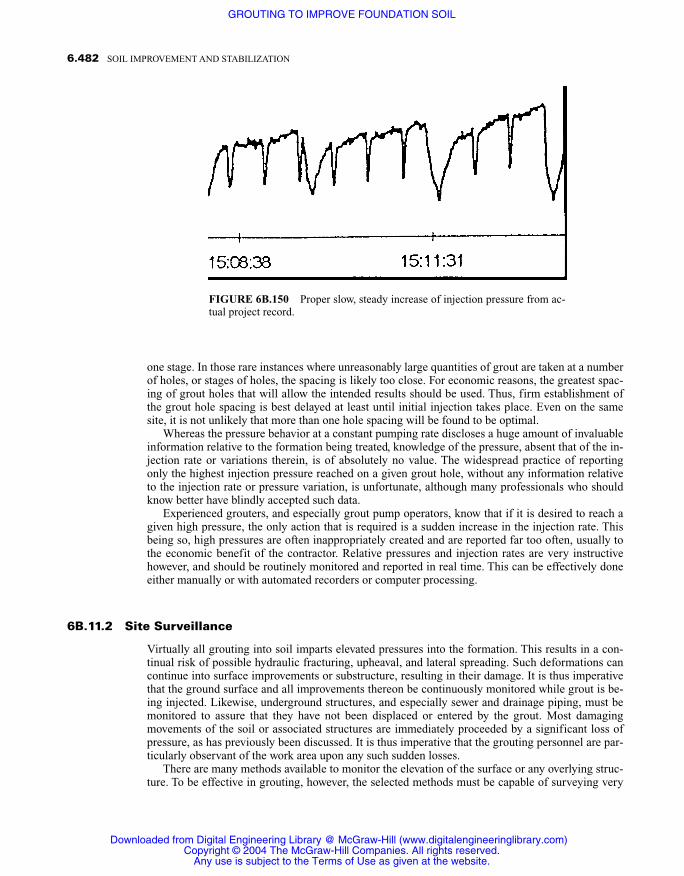
one stage. In those rare instances where unreasonably large quantities of grout are taken at a numberof holes, or stages of holes, the spacing is likely too close. For economic reasons, the greatest spac-ing of grout holes that will allow the intended results should be used. Thus, firm establishment ofthe grout hole spacing is best delayed at least until initial injection takes place. Even on the samesite, it is not unlikely that more than one hole spacing will be found to be optimal.
Whereas the pressure behavior at a constant pumping rate discloses a huge amount of invaluableinformation relative to the formation being treated, knowledge of the pressure, absent that of the in-jection rate or variations therein, is of absolutely no value. The widespread practice of reportingonly the highest injection pressure reached on a given grout hole, without any information relativeto the injection rate or pressure variation, is unfortunate, although many professionals who shouldknow better have blindly accepted such data.
Experienced grouters, and especially grout pump operators, know that if it is desired to reach agiven high pressure, the only action that is required is a sudden increase in the injection rate. Thisbeing so, high pressures are often inappropriately created and are reported far too often, usually tothe economic benefit of the contractor. Relative pressures and injection rates are very instructivehowever, and should be routinely monitored and reported in real time. This can be effectively doneeither manually or with automated recorders or computer processing.
6B.11.2 Site Surveillance
Virtually all grouting into soil imparts elevated pressures into the formation. This results in a con-tinual risk of possible hydraulic fracturing, upheaval, and lateral spreading. Such deformations cancontinue into surface improvements or substructure, resulting in their damage. It is thus imperativethat the ground surface and all improvements thereon be continuously monitored while grout is be-ing injected. Likewise, underground structures, and especially sewer and drainage piping, must bemonitored to assure that they have not been displaced or entered by the grout. Most damagingmovements of the soil or associated structures are immediately proceeded by a significant loss ofpressure, as has previously been discussed. It is thus imperative that the grouting personnel are par-ticularly observant of the work area upon any such sudden losses.
There are many methods available to monitor the elevation of the surface or any overlying struc-ture. To be effective in grouting, however, the selected methods must be capable of surveying very
6.482 SOIL IMPROVEMENT AND STABILIZATION
FIGURE 6B.150 Proper slow, steady increase of injection pressure from ac-tual project record.
Downloaded from Digital Engineering Library @ McGraw-Hill (www.digitalengineeringlibrary.com)Copyright © 2004 The McGraw-Hill Companies. All rights reserved.
Any use is subject to the Terms of Use as given at the website.
GROUTING TO IMPROVE FOUNDATION SOIL

6.483
FIG
UR
E 6
B.1
51C
ompu
ter-
gene
rate
d re
cord
of
grou
t inj
ecti
on p
aram
eter
s. N
ote
gene
rally
con
stan
t but
slo
wly
ris
ing
grou
t pre
ssur
e.
Downloaded from Digital Engineering Library @ McGraw-Hill (www.digitalengineeringlibrary.com)Copyright © 2004 The McGraw-Hill Companies. All rights reserved.
Any use is subject to the Terms of Use as given at the website.
GROUTING TO IMPROVE FOUNDATION SOIL

large areas and providing immediate notice of any movements. Thus, whereas conventional survey-ing can be useful, it usually is not satisfactory for the primary surveillance. Rotating laser instru-ments (Figure 6B.152), combined with multiple targets (Figure 6B.153) mounted on stands that aredistributed throughout the work area are quite effective.
Another method, which has been used on literally thousands of projects, is the multistationmanometer. Therein, one or more reservoirs, such as illustrated in Figure 6B.146, are used. Anynumber of tubes can be connected to a single reservoir, with the terminal end fixed to the groundsurface or on structures as desired. The precise water level is marked on the tube or adjacent mountprior to grout injection (Figure 6B.154). Any vertical movement that occurs will cause a change inthe water level, which is readily observed. In order to enhance visibility, the water can be colored,which is easily accomplished with a few drops of food color in the reservoir.
Multistation manometers are extremely flexible, as is the manner in which they are used. Fig-ure 6B.155 shows one of a number of tube terminals that have simply been attached to posts driv-en into the ground so as to be easily observable at normal eye level. A similar terminal, attachedto small stands that can be distributed over the ground surface, is illustrated in Figure 6B.156.Note that the tube is fixed at an angle to the vertical, so as to facilitate reading from a standingposition. Figure 6B.157 illustrates tubes from several different reservoir locations that are attachedto a common terminal board, enabling surveillance of an extended area from one location. In Fig-ure 6B.158 the terminal end of a tube is simply fixed to the wall of a structure with duct tape.
6.484 SOIL IMPROVEMENT AND STABILIZATION
FIGURE 6B.152 The signal from rotating laser instruments can cover a large planar area.
Downloaded from Digital Engineering Library @ McGraw-Hill (www.digitalengineeringlibrary.com)Copyright © 2004 The McGraw-Hill Companies. All rights reserved.
Any use is subject to the Terms of Use as given at the website.
GROUTING TO IMPROVE FOUNDATION SOIL

6.485GROUTING TO IMPROVE FOUNDATION SOIL
FIGURE 6B.154 The precise water level is noted when the instru-ments are set up.
FIGURE 6B.153 Any number of laser targetscan be mounted on stands distributed throughoutgrouting area.
Downloaded from Digital Engineering Library @ McGraw-Hill (www.digitalengineeringlibrary.com)Copyright © 2004 The McGraw-Hill Companies. All rights reserved.
Any use is subject to the Terms of Use as given at the website.
GROUTING TO IMPROVE FOUNDATION SOIL

Note the ruler that has been fixed with it, which will enable easy reading of the exact magnitudeof any movement.
Although they do not necessarily provide immediate surface movement measurements, conven-tional survey instruments can be quite useful, especially for the scanning of large areas. Figure6B.159 shows part of a large array of prisms that have been set into the slope of a dam. They are be-ing constantly swept by a total station located in the small protective shelter shown in Figure6B.160, in order to detect any movement of the slope.
Simple, inexpensive devices can also be very effective. A string line tightly stretched across aninjection site can be used for reference of the surface elevations. Small pieces of masking tape fixedover cracks will either deform or break if there is movement of the crack. For evaluation of the exactamount of movement, rulers or crack monitor gauges can be secured over cracks in structures (Fig-ures 6B.161 and 6B.162).
Nothing, however, replaces the eyes and ears of competent and alert grouting technicians. Figure6B.163 shows a worker “sweeping” the ground surface of loose material so as to expose a hardened
6.486 SOIL IMPROVEMENT AND STABILIZATION
FIGURE 6B.155 Manometer tube terminal attached to fence post drivenin ground.
Downloaded from Digital Engineering Library @ McGraw-Hill (www.digitalengineeringlibrary.com)Copyright © 2004 The McGraw-Hill Companies. All rights reserved.
Any use is subject to the Terms of Use as given at the website.
GROUTING TO IMPROVE FOUNDATION SOIL

6.487GROUTING TO IMPROVE FOUNDATION SOIL
FIGURE 6B.157 Terminals from several reservoirs are placed together for easy readout.
FIGURE 6B.156 Readout terminal mounted on small stand.
Downloaded from Digital Engineering Library @ McGraw-Hill (www.digitalengineeringlibrary.com)Copyright © 2004 The McGraw-Hill Companies. All rights reserved.
Any use is subject to the Terms of Use as given at the website.
GROUTING TO IMPROVE FOUNDATION SOIL
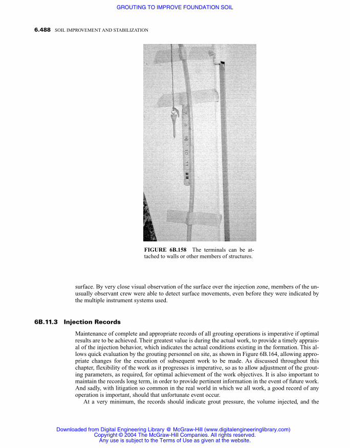
surface. By very close visual observation of the surface over the injection zone, members of the un-usually observant crew were able to detect surface movements, even before they were indicated bythe multiple instrument systems used.
6B.11.3 Injection Records
Maintenance of complete and appropriate records of all grouting operations is imperative if optimalresults are to be achieved. Their greatest value is during the actual work, to provide a timely apprais-al of the injection behavior, which indicates the actual conditions existing in the formation. This al-lows quick evaluation by the grouting personnel on site, as shown in Figure 6B.164, allowing appro-priate changes for the execution of subsequent work to be made. As discussed throughout thischapter, flexibility of the work as it progresses is imperative, so as to allow adjustment of the grout-ing parameters, as required, for optimal achievement of the work objectives. It is also important tomaintain the records long term, in order to provide pertinent information in the event of future work.And sadly, with litigation so common in the real world in which we all work, a good record of anyoperation is important, should that unfortunate event occur.
At a very minimum, the records should indicate grout pressure, the volume injected, and the
6.488 SOIL IMPROVEMENT AND STABILIZATION
FIGURE 6B.158 The terminals can be at-tached to walls or other members of structures.
Downloaded from Digital Engineering Library @ McGraw-Hill (www.digitalengineeringlibrary.com)Copyright © 2004 The McGraw-Hill Companies. All rights reserved.
Any use is subject to the Terms of Use as given at the website.
GROUTING TO IMPROVE FOUNDATION SOIL

6.489GROUTING TO IMPROVE FOUNDATION SOIL
FIGURE 6B.159 Part of a large array of survey prisms covering the face of a dam dur-ing grouting.
FIGURE 6B.160 Prisms were constantly scanned from a survey total station insideprotective shelter.
Downloaded from Digital Engineering Library @ McGraw-Hill (www.digitalengineeringlibrary.com)Copyright © 2004 The McGraw-Hill Companies. All rights reserved.
Any use is subject to the Terms of Use as given at the website.
GROUTING TO IMPROVE FOUNDATION SOIL

6.490 SOIL IMPROVEMENT AND STABILIZATION
FIGURE 6B.162 Crack monitor can give very accurate measurements of any crackmovement.
FIGURE 6B.161 Ruler fastened over crack in a wall to monitor anychanges in its width.
Downloaded from Digital Engineering Library @ McGraw-Hill (www.digitalengineeringlibrary.com)Copyright © 2004 The McGraw-Hill Companies. All rights reserved.
Any use is subject to the Terms of Use as given at the website.
GROUTING TO IMPROVE FOUNDATION SOIL

6.491GROUTING TO IMPROVE FOUNDATION SOIL
FIGURE 6B.164 Supervisors analyzing injection data as it is procured.
FIGURE 6B.163 Sweeping loose material off of earth surface to enable closer visualinspection of surface.
Downloaded from Digital Engineering Library @ McGraw-Hill (www.digitalengineeringlibrary.com)Copyright © 2004 The McGraw-Hill Companies. All rights reserved.
Any use is subject to the Terms of Use as given at the website.
GROUTING TO IMPROVE FOUNDATION SOIL

time at regular intervals. Obviously, the date, time, hole number, and grout stage depths should al-ways be provided. Although it is convenient to also have the grout flow rate recorded, this can beback calculated if the time and volume are noted. Where suspension grouts are being used, continu-ous monitoring of the grout density will provide precise values of the ratio of water to solids. Thiscan thus be an excellent quality assurance procedure.
If the records are being generated manually, entries should made at all pressure movements, suchthat the pressure behavior can be plotted against time. Figure 6B.165 shows a typical form for man-ual recording of individual grout holes. It is also important, to consider the highlights of all holesand their interrelation. This is conveniently done on a form such as that provided in Figure 6B.166,where the overall grout performance can be viewed. It has been the writer’s experience that manygrouting professionals tend to analyze in great detail the activity of individual grout holes, butsometimes fail to observe the trends of the overall performance. It is important to occasionally standback and view the overall grouting operation. Understanding how the individual holes behave andinteract often clarifies scatter in the individual hole data.
On large or important projects, either continuous chart recorders or automated data acquisitionsystems with direct connection to a computer should be used. Computer software programs are nowavailable, and others are being developed, especially for the monitoring of grout injection. Also,some grouting specialty contractors have their own proprietary programs. A substantial advantageof computer monitoring is the ability to immediately output the data in a suitable form for closer ob-servation or further analysis. Also, data formats that are computer generated can usually be adjustedin exaggerated scale or otherwise manipulated so as to aid in interpretation of specific events.
Even where the data acquisition is manual, it is advantageous to enter it into a computer data-base, such as Microsoft Excel, so that graphical output is facilitated. Figure 6B.167 illustrates bargraphs from one of the first holes grouted on an actual project. As can be observed, the grout takeand pressure are shown side by side as a function of depth. It is noteworthy that grout takes werequite low at depths greater than about 28 feet, even though relatively high injection pressures wereused. Following similar behavior on a number of distributed primary holes, a decision was made toreduce the depth of the drilling and grouting for the remainder of the work.
Similar data for a grout hole on another actual project is shown in Figure 6B.168. Here it will benoted that in spite of the injection rate and pressure remaining generally uniform, very large groutquantities were injected in a region at about mid-hole depth. By magnifying the grout volume fig-ure, as in Figure 6B.169, the areas of high take are even more obvious. When several such recordsare assembled on the wall according to their relative positioning on the site, as illustrated in Figure6B.170, it becomes very easy to recognize the relatively limited zone of high take and thus faultybeginning soil. The writer has found this format especially useful for displaying the data as it is de-veloped on the jobsite. Records so posted, for each hole or hole stage, allow for even the lower leveltechnicians to visualize the position of the overall grout deposition zones. This ability to quicklycomprehend the overall project status is very helpful in determining how best to proceed. As an ex-ample, the posted data shown in Figure 6B.170 would suggest that depth of future holes need not beas great, as long as they extended through the zone of large take.
6B.11.4 Be Prepared for Changes!
Aside from the fact that geology and geotechnical engineering are not perfect sciences, from a prac-tical standpoint, it is never possible to have a complete understanding of the subsurface conditionsinto which grout will be injected. As has been amply mentioned throughout this chapter, flexibilityof a grouting program is thus mandatory if the optimal performance is to be realized. It is not un-usual to find large grout takes in only a portion of the soil zone to be treated, as was the case in theproject for which the grouting records are depicted in Figures 6B.168, 169, and 170. The ability tochange both the grout hole spacing and grout deposition stage lengths and depths can be of great ad-vantage in optimizing any grouting program. This is particularly true when working in older urbanareas that have historically experienced considerable underground construction, for which the de-
6.492 SOIL IMPROVEMENT AND STABILIZATION
Downloaded from Digital Engineering Library @ McGraw-Hill (www.digitalengineeringlibrary.com)Copyright © 2004 The McGraw-Hill Companies. All rights reserved.
Any use is subject to the Terms of Use as given at the website.
GROUTING TO IMPROVE FOUNDATION SOIL

6.493
FIG
UR
E 6
B.1
65A
typi
cal f
orm
for
man
ual r
ecor
ding
of
grou
t inj
ecti
on d
ata.
Downloaded from Digital Engineering Library @ McGraw-Hill (www.digitalengineeringlibrary.com)Copyright © 2004 The McGraw-Hill Companies. All rights reserved.
Any use is subject to the Terms of Use as given at the website.
GROUTING TO IMPROVE FOUNDATION SOIL

6.494
FIG
UR
E 6
B.1
66P
laci
ng a
ll d
ata
on a
sum
mar
y fo
rm e
nabl
es o
vera
ll in
terp
reta
tion
of
oper
atio
n.
Downloaded from Digital Engineering Library @ McGraw-Hill (www.digitalengineeringlibrary.com)Copyright © 2004 The McGraw-Hill Companies. All rights reserved.
Any use is subject to the Terms of Use as given at the website.
GROUTING TO IMPROVE FOUNDATION SOIL

6.495
FIG
UR
E 6
B.1
67C
ompu
ter
data
base
-gen
erat
ed g
raph
sho
win
g bo
th g
rout
vol
umes
and
pre
ssur
es f
or a
gro
ut h
ole.
Downloaded from Digital Engineering Library @ McGraw-Hill (www.digitalengineeringlibrary.com)Copyright © 2004 The McGraw-Hill Companies. All rights reserved.
Any use is subject to the Terms of Use as given at the website.
GROUTING TO IMPROVE FOUNDATION SOIL

6.496
FIG
UR
E 6
B.1
68S
imil
ar o
utpu
t gra
phs.
Not
e la
rge
grou
t tak
es a
re li
mit
ed to
mid
dep
th o
f ho
les.
Downloaded from Digital Engineering Library @ McGraw-Hill (www.digitalengineeringlibrary.com)Copyright © 2004 The McGraw-Hill Companies. All rights reserved.
Any use is subject to the Terms of Use as given at the website.
GROUTING TO IMPROVE FOUNDATION SOIL

6.497
FIG
UR
E 6
B.1
69B
low
up in
exa
gger
ated
sca
le o
f th
e ri
ght p
orti
on o
f Fi
gure
6B
.168
hig
hlig
hts
grou
t dis
trib
utio
n in
the
grou
t hol
e.
Downloaded from Digital Engineering Library @ McGraw-Hill (www.digitalengineeringlibrary.com)Copyright © 2004 The McGraw-Hill Companies. All rights reserved.
Any use is subject to the Terms of Use as given at the website.
GROUTING TO IMPROVE FOUNDATION SOIL

tails are not known. Even in those cases where good records of prior underground works are avail-able, important details may be missing.
As a very young contractor, in the mid 1950s, the writer had a job to re-level a settled swimmingpool by grouting. The pool was constructed in clayey-silt soil, which filled the basement of a build-ing that had previously occupied the site. Leakage from the newly constructed pool had saturatedthe fill soil, which had apparently not been properly compacted. At the time, grout improvement ofsuch fine-grained soils was not considered possible, and the work was to be limited to leveling thepool shell. On commencement of grout injection, a steady flow of water entered the pool from adja-cent grout holes. This continued for many hours before the pool finally began to rise as planned.About nine times the quantity of grout, which by calculation would have raised the pool as planned,had been required! And throughout the injection, what was thought to be a similar amount of waterwas bailed out of the pool.
The only logical explanation was that the force of the grout “squeezed” the water out of the soil,thereby densifying it. Although the job was a financial disaster for the contractor, who had agreed todo it for a lump-sum price, the geotechnical engineer considered it the most wonderful event of hiscareer. You see, he explained, it’s not supposed to be possible to squeeze water out of soil so easily;this is wonderful! And that was the beginning of the writer’s research, which led to his currentknowledge of the compaction grouting mechanism. Wonderful it was, though it didn’t seem so at thetime.
6.498 SOIL IMPROVEMENT AND STABILIZATION
FIGURE 6B.170 Assembling volume graphs in the same layout as the grout holes allows easy recognition of the groutdeposition locations.
Downloaded from Digital Engineering Library @ McGraw-Hill (www.digitalengineeringlibrary.com)Copyright © 2004 The McGraw-Hill Companies. All rights reserved.
Any use is subject to the Terms of Use as given at the website.
GROUTING TO IMPROVE FOUNDATION SOIL

In another memorable project for the fledgling firm, remedial grouting in connection with thesettlement of some railroad tracks was to be performed. Many years prior, a small tunnel had beenexcavated, about 30 feet under the tracks, in which a sewer pipe was placed. The soil was very sandyand although the records were sketchy, it was believed the tunnel was solidly shored with continu-ous sets of timber planks. The tunnel, which was only about 25 feet long, was said to have beenbackfilled with “jetted” sand. Payment for the grout, which was specified to be a cementitious sus-pension, was by the bag of cement. The contract quantity estimate was for 350 bags.
Penetration of about three inches (7.5 cm) of timber over the tunnel roof during drilling con-firmed the expected shoring. A drop of the drill steel upon penetration of the timber, however, was asurprise. The contractor’s people reported what they felt were voids, varying from a few inches up tomore than one foot. The owner’s inspector, who had not shown much regard for the novice grouter,however, insisted the contract estimate was correct, with a cryptic comment to the effect “when youget more experience, you’ll know the difference between loose sand and voids.”
Four thousand bags of cement later, the voids were filled. For the young contractor it was a veryprofitable job, and almost offset the losses on the pool! But more importantly, it offered a valuablelesson. Subsurface conditions are not always what we expect, and don’t ever believe, you reallyknow what you think you know (as did the arrogant inspector). Surprises do occur in the groutingbusiness.
Another interesting example is in the failure of a four year old sewer, which had been construct-ed quite deep in an area of generally poor soils with a high groundwater level. Following the devel-opment of a sinkhole over the line, internal inspection disclosed some minor distortions of the invertalignment, suggesting questionable stability of the pipe bedding, which consisted of a 12 inch (30cm) thickness of one inch gravel. The selected repair provided for injection of a cementitious groutinto the pore spaces of the bedding gravel, to in essence solidify it into a rigid concrete. After a fewdays of uneventful injection, a large pressure drop occurred. The first thought was that the grout wasentering the pipe, but inspection found that not to be the case. After careful evaluation determinedthat no other substructure existed in near proximity to the area of grout leakage, injection proceed-ed, but with very close observation of the pressure behavior. It was indicative of the filling of asmall open pipe for about four cubic feet of grout, after which normal behavior returned. Subse-quent discussions with the inspector of the original work disclosed that during construction the con-tractor occasionally embedded slotted pipe in the bedding rock, as part of the dewatering effort. Norecords existed of this detail, and had it not been for the memory of the inspector, the otherwiseharmless anomaly would have remained a mystery.
This brings to mind a similar incident, which did not turn out to be so harmless. In the early1960s, the writer’s contracting firm was retained to do some remedial grouting under the maincourthouse in Los Angeles. A tunnel had been excavated under the existing basement to provide ac-cess from a new underground parking structure. The tunnel passed under the heavily loaded slab-on-grade floor of an evidence storage area, by a depth of only about four feet (1.2 m). The floor slabhad settled about three inches (7.5 cm) over the tunnel alignment. Slabjacking with a low-mobilitygrout was to be used to raise the floor to its proper grade, followed by compaction grouting of thesoil down to the tunnel roof. Because this was in an active public building, all work was done atnight. Grouting had a rather poor reputation at the time, and the owners’ maintenance staff was con-cerned about possible damage to the existing facilities. They thus had a plumber present at all timesduring grout injection.
One night the grouting foreman observed pressure behavior indicative of the grout entering apipe. He halted injection and informed the plumber that he thought the grout was getting into a pipeof some sort. On his manual record form was a comment, “stopped grout—told the plumber I thinkI’m in a pipe,” with the time noted. About 10 minutes later, a further comment was entered,“Plumber says everything OK,” with the time noted. Injection was resumed, but a further note afterabout ten minutes stated, “Told plumber know I’m into something—stopped grouting—hole aban-doned.” Following that were notes addressing further word from the plumber that he had checked alllines, they were clear, and there was no reason to stop grouting.
Some months later, when the first rain of the season fell, it was found that the grout was indeed
6.499GROUTING TO IMPROVE FOUNDATION SOIL
Downloaded from Digital Engineering Library @ McGraw-Hill (www.digitalengineeringlibrary.com)Copyright © 2004 The McGraw-Hill Companies. All rights reserved.
Any use is subject to the Terms of Use as given at the website.
GROUTING TO IMPROVE FOUNDATION SOIL

in “something” and the plumber was wrong. A 10 inch (25.4 cm) cast iron pipe that served as a col-lector for the entire roof drainage system and crossed the tunnel alignment was filled with grout! Inrepairing that problem, it was found that the probable cause of the original settlement had been leak-age from that pipe as a result of disturbance during tunneling. Fortunately for the contractor, the vig-ilance of an extremely competent foreman and his notation on the grouting records relieved him ofresponsibility for what turned out to be a very expensive event. As stated many times throughoutthis chapter, continuous pressure behavior monitoring and recording should be mandatory in allgrouting work!
In another instance, differential settlement of several inches had occurred in a large commercialbuilding. The building, which was only about a year old, had been built on one edge of a deepcanyon fill. The geotechnical investigation did not reveal any obviously poor underlying soil, but asthe fill was not up to the specified density, compaction grouting was called for. Primary grout holeswere spaced about twenty feet on center, along the outside of the foundation of the wall that had ex-perienced the greatest damage. Drilling indicated nothing noteworthy, and only minor amounts ofgrout, with very uniform pressure buildup, were injected in the first several holes. But then came asurprise! At a depth of about 40 feet (12 m), one of the holes exhibited very irregular pressure be-havior, and took a very large quantity of grout. This was followed by similar behavior at a depth ofabout 35 feet (10.5 m) in another hole.
Reevaluation of the available site grading data suggested that a pioneering haul road might havetreaded up the canyon under the building. Working on this assumption, grout holes were establishedover the suspected haul road location. Indeed, large quantities of grout were taken in only one or twostages, at various depths, in those holes. Plotting those locations indicated a uniform gradient, typi-cal of a haul road. Apparently, loose slope-wash and fill existed on the downhill side of the haulroad. With this knowledge, the grouting program was reevaluated. Further work was limited to thearea of the suspected haul road, reducing the cost of the work to less than half of that which was ex-pected going into the job. This resulted in a very happy owner. Although the grouting contractor hadthe job cut short, he more than made up for the lost revenue by referrals and future work from theowner and his geotechnical engineer.
6B.11.5 Verification of Grouting Effectiveness
Much has been written and discussed about verification of the effectiveness of grouting, and in factthe American Society of Civil Engineers GeoInstitute Committee on Grouting had an entire sessionon the subject at a 1995 meeting, the proceedings of which are available (Byle and Borden, 1995).This notwithstanding, although many grouters talk verification as part of their promotion, the sadfact is that relatively little effort has been shown by grouters to really understand the quality (or lackof quality) of their work, especially in the United States.
From a practical and economic standpoint, the most meaningful verification of the results of vir-tually all grouting operations occur as the grout is being injected. This is through continuous obser-vation and control of the various injection parameters, especially the rate of injection and pressurebehavior. It is the writer’s considered opinion that no amount of postinjection investigation or testingcan duplicate the benefit of careful monitoring and control during the actual grout injection. Thereare however, a variety of postgrouting tests that can, to a varying degree, confirm the completenessand the general quality of the grouted mass.
In water-control grouting, if the leaking areas are clearly visible, such as leakage into an under-ground pipe or structure, direct observation of the cessation of the leakage is certainly acceptableverification. If the site of the leakage is not clearly visible, such as an impermeable curtain under adam, downstream boreholes will be required.
Where permeation grouting has been used for strengthening of the soil, test excavations or bor-ings can be made. The completeness of the solidification can thus be readily observed, and speci-mens of the grouted soil can be obtained for laboratory evaluation of the strength. It must be re-membered that the fundamental strength, which is the strength under a continuous load, of solution
6.500 SOIL IMPROVEMENT AND STABILIZATION
Downloaded from Digital Engineering Library @ McGraw-Hill (www.digitalengineeringlibrary.com)Copyright © 2004 The McGraw-Hill Companies. All rights reserved.
Any use is subject to the Terms of Use as given at the website.
GROUTING TO IMPROVE FOUNDATION SOIL
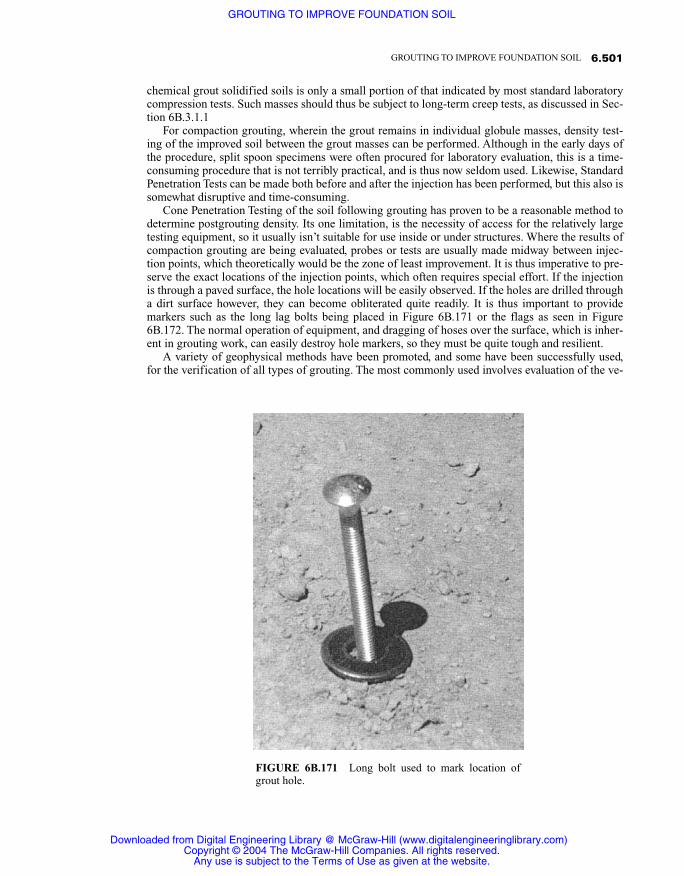
chemical grout solidified soils is only a small portion of that indicated by most standard laboratorycompression tests. Such masses should thus be subject to long-term creep tests, as discussed in Sec-tion 6B.3.1.1
For compaction grouting, wherein the grout remains in individual globule masses, density test-ing of the improved soil between the grout masses can be performed. Although in the early days ofthe procedure, split spoon specimens were often procured for laboratory evaluation, this is a time-consuming procedure that is not terribly practical, and is thus now seldom used. Likewise, StandardPenetration Tests can be made both before and after the injection has been performed, but this also issomewhat disruptive and time-consuming.
Cone Penetration Testing of the soil following grouting has proven to be a reasonable method todetermine postgrouting density. Its one limitation, is the necessity of access for the relatively largetesting equipment, so it usually isn’t suitable for use inside or under structures. Where the results ofcompaction grouting are being evaluated, probes or tests are usually made midway between injec-tion points, which theoretically would be the zone of least improvement. It is thus imperative to pre-serve the exact locations of the injection points, which often requires special effort. If the injectionis through a paved surface, the hole locations will be easily observed. If the holes are drilled througha dirt surface however, they can become obliterated quite readily. It is thus important to providemarkers such as the long lag bolts being placed in Figure 6B.171 or the flags as seen in Figure6B.172. The normal operation of equipment, and dragging of hoses over the surface, which is inher-ent in grouting work, can easily destroy hole markers, so they must be quite tough and resilient.
A variety of geophysical methods have been promoted, and some have been successfully used,for the verification of all types of grouting. The most commonly used involves evaluation of the ve-
6.501GROUTING TO IMPROVE FOUNDATION SOIL
FIGURE 6B.171 Long bolt used to mark location ofgrout hole.
Downloaded from Digital Engineering Library @ McGraw-Hill (www.digitalengineeringlibrary.com)Copyright © 2004 The McGraw-Hill Companies. All rights reserved.
Any use is subject to the Terms of Use as given at the website.
GROUTING TO IMPROVE FOUNDATION SOIL

locity of stress waves traveling through the formation, commonly referred to as seismic tomography.Simply stated, sound travels faster through a hard medium than a soft one. Thus, a densified or so-lidified mass will usually possess a higher velocity than adjacent soil that has not been grouted. Byanalysis and interpretation of the velocity and attenuation of a large number of sound waves drivenat different inclinations through a profile of the soil formation, the relative density or stiffness of thevarious components of that profile can be determined.
In application, evaluation is usually preformed between two bore holes. A transmitter in one ofthe holes initiates a pulse, which is picked up by a receiver in the adjacent hole. Typically, the trans-mitter will be moved vertically in the bore hole, so as to direct pulses to the receiver at a variety ofangles. The receiver usually remains at one location within its hole for a given set of data. By chang-ing the depth of the receiver, multiple sets of data are obtained, with which a seismic profile can bedeveloped. The waves can be either shear waves, which are perpendicular to the bore hole, or com-pressional waves, which are parallel thereto. Compressional waves are the most frequently used, astheir analysis is simpler. Whereas stress wave velocities are usually determined with direct paths be-tween two bore holes (cross-bore hole survey) or by analysis of reflective rays, some work has alsobeen accomplished by directing waves from transmitters and receivers, which are both placed on theground surface. The effective depth of the so-called surface procedure is a function of the distance
6.502 SOIL IMPROVEMENT AND STABILIZATION
FIGURE 6B.172 Small surveyor’s flag to mark location of grout hole. Note that the hole identificationand date grouted are also shown, as is the comment “Bad Boy,” which apparently indicates some difficul-ty with the grouting.
Downloaded from Digital Engineering Library @ McGraw-Hill (www.digitalengineeringlibrary.com)Copyright © 2004 The McGraw-Hill Companies. All rights reserved.
Any use is subject to the Terms of Use as given at the website.
GROUTING TO IMPROVE FOUNDATION SOIL

between the transmitter and receiver. As the accuracy of the resulting plots, which are known as to-mograms, is dependent upon the number of individual ray paths and resulting nodal intersectionsthat are evaluated, the down hole evaluation is preferred.
To produce tomograms from the ray path data requires extensive data processing, which is prac-ticable only with specialized computer software programs. For these reasons, such work is common-ly performed only by firms who possess the highly specialized knowledge and equipment. This,plus the requirement of very large numbers of different ray paths to provide accurate determina-tions, makes the procedure somewhat expensive, and it is thus usually reserved for especially largeor important applications. Where the budget allows for acquisition of sufficient data, however, theprocedure has been found to accurately portray the existing conditions and provide valuable infor-mation.
Another geophysical method, as reported by Rehwoldt, Matheson, and Dunscomb (1999) is two-dimensional imagery, generated by electrical resistivity surveys. Therein, the conductivity of theformation is evaluated by placing a consistently spaced line of electrodes on the ground surface.They are driven into the soil to a depth of about 12 inches (30 cm) and connected to a computer-guided resistivity meter. The meter takes measurements along the electrode array, using four elec-trodes at a time. The depth of the evaluation is dependent upon the spacing of the surface electrodes.
Special computer software is then used to evaluate all possible combinations of current flow andanalyze the data to locate areas of anomalously high or low resistivity. Soil and rock are basicallynonconductive materials; however, both virtually always contain moisture. It is the moisture contentthat determines the conductivity of the various components that make up a particular formation. Asexamples, dry rock is quite resistive, whereas submerged clays are highly conductive. Accordingly,an area that was of very low density or perhaps an obvious void prior to grouting will exhibit differ-ent electrical behavior after being grouted.
Ground probing radar is another process that has been considered; however, with present tech-nology, the accuracy and precision of its output is not as great as that of the previously describedseismic methods. In radar evaluation, an electromagnetic pulse is generated on the ground surface.It is then reflected from the various interfaces at depth to a retrieval instrument on the surface.Equipment is available that can traverse the surface radiating and receiving repetitive electromag-netic pulses, so as to obtain a continuous record of the subsurface interfaces along the route tra-versed.
Ground probing radar instruments basically measure variations in the electromagnetic velocityof the different formation materials encountered. The procedure is thus especially useful for iden-tifying clear interfaces, such as the presence of buried pipelines or subsurface concrete structureswithin a soil mass. Likewise, where the velocities of different soils in a grouted formation varygreatly, or have clearly different water contents and/or chemistry, identification of the boundariesmay be viable. In most grouting applications, however, the variations of electromagnetic velocitybetween the grout and the soil are more subtle, and the applicability of the process is thus less ad-vantageous. As with advanced monitoring in general, the process is in constant development andadvancement. It may thus become more applicable to the verification of grouting work in the fu-ture.
6B.11.6 Grouting Specifications and Contracts
Although grouting is very much a technology, it is a specialized area of activity for most owners andtheir engineers, most of whom do not practice it regularly. There are however, many geotechnicalengineering firms that have professionals with considerable experience, as well as several individualconsultants. Perhaps those in the best position to maintain expertise in the technology, however, arethe contractors who regularly perform the work. Many possess the specialized knowledge andequipment, and have the experienced personnel to optimally perform the work. Specificationsshould not be so limited or stringent that well-qualified contractors will be precluded from use oftheir innovations and special expertise.
6.503GROUTING TO IMPROVE FOUNDATION SOIL
Downloaded from Digital Engineering Library @ McGraw-Hill (www.digitalengineeringlibrary.com)Copyright © 2004 The McGraw-Hill Companies. All rights reserved.
Any use is subject to the Terms of Use as given at the website.
GROUTING TO IMPROVE FOUNDATION SOIL
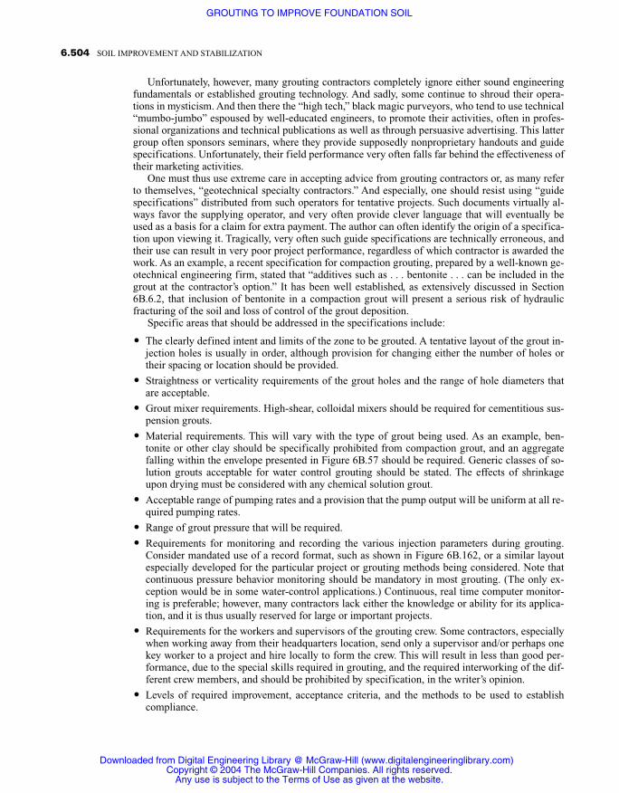
Unfortunately, however, many grouting contractors completely ignore either sound engineeringfundamentals or established grouting technology. And sadly, some continue to shroud their opera-tions in mysticism. And then there the “high tech,” black magic purveyors, who tend to use technical“mumbo-jumbo” espoused by well-educated engineers, to promote their activities, often in profes-sional organizations and technical publications as well as through persuasive advertising. This lattergroup often sponsors seminars, where they provide supposedly nonproprietary handouts and guidespecifications. Unfortunately, their field performance very often falls far behind the effectiveness oftheir marketing activities.
One must thus use extreme care in accepting advice from grouting contractors or, as many referto themselves, “geotechnical specialty contractors.” And especially, one should resist using “guidespecifications” distributed from such operators for tentative projects. Such documents virtually al-ways favor the supplying operator, and very often provide clever language that will eventually beused as a basis for a claim for extra payment. The author can often identify the origin of a specifica-tion upon viewing it. Tragically, very often such guide specifications are technically erroneous, andtheir use can result in very poor project performance, regardless of which contractor is awarded thework. As an example, a recent specification for compaction grouting, prepared by a well-known ge-otechnical engineering firm, stated that “additives such as . . . bentonite . . . can be included in thegrout at the contractor’s option.” It has been well established, as extensively discussed in Section6B.6.2, that inclusion of bentonite in a compaction grout will present a serious risk of hydraulicfracturing of the soil and loss of control of the grout deposition.
Specific areas that should be addressed in the specifications include:
� The clearly defined intent and limits of the zone to be grouted. A tentative layout of the grout in-jection holes is usually in order, although provision for changing either the number of holes ortheir spacing or location should be provided.
� Straightness or verticality requirements of the grout holes and the range of hole diameters thatare acceptable.
� Grout mixer requirements. High-shear, colloidal mixers should be required for cementitious sus-pension grouts.
� Material requirements. This will vary with the type of grout being used. As an example, ben-tonite or other clay should be specifically prohibited from compaction grout, and an aggregatefalling within the envelope presented in Figure 6B.57 should be required. Generic classes of so-lution grouts acceptable for water control grouting should be stated. The effects of shrinkageupon drying must be considered with any chemical solution grout.
� Acceptable range of pumping rates and a provision that the pump output will be uniform at all re-quired pumping rates.
� Range of grout pressure that will be required.
� Requirements for monitoring and recording the various injection parameters during grouting.Consider mandated use of a record format, such as shown in Figure 6B.162, or a similar layoutespecially developed for the particular project or grouting methods being considered. Note thatcontinuous pressure behavior monitoring should be mandatory in most grouting. (The only ex-ception would be in some water-control applications.) Continuous, real time computer monitor-ing is preferable; however, many contractors lack either the knowledge or ability for its applica-tion, and it is thus usually reserved for large or important projects.
� Requirements for the workers and supervisors of the grouting crew. Some contractors, especiallywhen working away from their headquarters location, send only a supervisor and/or perhaps onekey worker to a project and hire locally to form the crew. This will result in less than good per-formance, due to the special skills required in grouting, and the required interworking of the dif-ferent crew members, and should be prohibited by specification, in the writer’s opinion.
� Levels of required improvement, acceptance criteria, and the methods to be used to establishcompliance.
6.504 SOIL IMPROVEMENT AND STABILIZATION
Downloaded from Digital Engineering Library @ McGraw-Hill (www.digitalengineeringlibrary.com)Copyright © 2004 The McGraw-Hill Companies. All rights reserved.
Any use is subject to the Terms of Use as given at the website.
GROUTING TO IMPROVE FOUNDATION SOIL

The use of open competitive bidding for most grouting work should be avoided, if possible. It servesas an invitation to lesser qualified and often shady operators, of which, unfortunately, there aremany in the grouting business. Although public agencies are usually limited to the use of open bid-ding for their work, it is possible even for them to require meaningful prequalification of contractorsfor highly specialized work such as grouting, and many public projects have been so bid.
As a minimum, bidding should be limited to entirely prequalified contractors. Prequalificationshould not be given without a through appraisal of the individual applicants, which will include con-tacting the owners and/or engineers of several prior similar projects. Several is emphasized, as refer-ences given by some contractors in the past have turned out to be fraudulent. Additionally, evenshoddy operators have an occasional project that has turned out well.
Continuity of a contractor’s activity is also important. A contractor that has not preformed simi-lar grouting work for an extended period of time is not likely to have working crews organized forthat type of work. Use of a prequalification form such as that provided as Figure 6B.173 is stronglyrecommended. It is also a good idea to visit the contractor’s headquarters, not only to confirm thestatements made in the prequalification submittal, but also to see firsthand the manner in which heoperates, such as orderliness of the equipment and facilities.
Where possible, rather than have competitive bidding, it is strongly recommended that a contractbe negotiated with a thoroughly qualified and honest contractor. Oftentimes, these will be regionalfirms, which do not advertise but depend upon recommendation and repeat work instead. Locatingthem will thus require considerable effort, but that effort will be well placed, in that a better qualityfinished product, delivered in a timely manner and at a lower ultimate cost, will likely result. Theimportance of due diligence in selecting a contractor cannot be overemphasized. This should startwith the completion of a prequalification submittal, including the information enumerated in Figure6B.173.
In assessing the submittal, all entries should be independently verified, for very often, less thanhonest responses are made. The writer finds it distressing that so much dishonesty exists in thegrouting business, but it does, and it must be recognized. As an example, one contractor respondedin a submittal, that he was going to use a certain make and model of batching and mixing plant on aproject. He further stated that he was going to rent it from Hertz Equipment Rental in Denver Col-orado, and that he had a commitment that the equipment would be available to him should he re-ceive the project. A simple phone call to the designated renter revealed that they did not own anysuch plants, but advised calling an 800 number, which connected to their national equipment inven-tory. A call there disclosed that the firm did not own any such equipment nationwide!
In another case, a contractor was awarded a project based on his proposal to use continuouscomputer monitoring, which involved a “proprietary software program specifically for the com-paction grouting” that only he possessed. When the writer visited the project, a computer was in-deed set up on a table in the injection area. Unfortunately, the only data that was being recorded wasthe hole number, which was entered manually, and pressure readings transmitted from a pressuretransducer at the grout collar, which operated only sporadically. There was no mention of the injec-tion rate and, of course, this rendered the pressure values of no usefulness whatsoever. The claim ofuse and setup of the computer on the work site did indeed look impressive. Unfortunately, this wassimply a ruse to imply special competence, which the contractor did not possess. As for the propri-etary software, it was nonexistent! And in the eyes of the writer, the entire operation was a sham.
The fact is, there are some brilliant advertising and proposal writers in the grouting industry.Sadly, they are not always so brilliant in carrying out the work, once it is awarded to them, andsometimes their presentations are downright dishonest. It is not unusual to find that once on theproject, the formulation of often frivolous claims appears to take precedence over good performanceof the work. One must be very cautious in accepting information from grouting contractors, and in-dependent confirmation of the appropriateness and the accuracy of such is essential. Fortunately,there are some very good operators that are both honest and very knowledgeable, and therefore ex-cellent sources of guidance.
Finally, unless the work to be done is quite routine, and the soil profile and the existing condi-tions are well understood, full-scale test injections are strongly recommended. Successful comple-
6.505GROUTING TO IMPROVE FOUNDATION SOIL
Downloaded from Digital Engineering Library @ McGraw-Hill (www.digitalengineeringlibrary.com)Copyright © 2004 The McGraw-Hill Companies. All rights reserved.
Any use is subject to the Terms of Use as given at the website.
GROUTING TO IMPROVE FOUNDATION SOIL
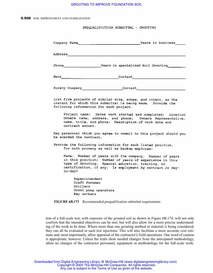
tion of a full-scale test, with exposure of the grouted soil as shown in Figure 6B.174, will not onlyconfirm that the intended objectives can be met, but will also allow for a more precise understand-ing of the work to be done. Where more than one grouting method or material is being considered,they can all be evaluated in such test injections. This will also facilitate a more accurate cost esti-mate and, most importantly, allow appraisal of the contractor’s field operations. One word of cautionis appropriate, however. Unless the trials show needed changes from the anticipated methodology,allow no changes of the contractor personnel, equipment or methodology for the full-scale work.
6.506 SOIL IMPROVEMENT AND STABILIZATION
FIGURE 6B.173 Recommended prequalification submittal requirements.
Downloaded from Digital Engineering Library @ McGraw-Hill (www.digitalengineeringlibrary.com)Copyright © 2004 The McGraw-Hill Companies. All rights reserved.
Any use is subject to the Terms of Use as given at the website.
GROUTING TO IMPROVE FOUNDATION SOIL

There have been instances where grouting contractors have performed brilliantly on test applica-tions, so as to qualify for the production work, but then used less costly procedures, resulting in in-ferior performance once the production contract was received.
6B.12 SOME FINAL THOUGHTS
When the writer first entered the world of grouting in 1952, there was virtually no established tech-nology for the grouting of soils. The large government agencies that managed major dams each hadits own ideas on how grouting should be done, although, interestingly, there was not a great deal ofagreement between them. The contractors generally operated behind a veil of mysticism, and therewas virtually no sharing of knowledge. Most grouting in that era, was in rock, and grouting in soilwas generally unheard of.
Because grouting in soil is of relatively recent origin, and some of the main players, includingthe writer, were not part of the established club of “magic grouters,” development of the technologyfor soil grouting, and especially that of compaction grouting, has been much more openly discussedand orderly. The technology for grouting in soil is to a large degree better understood, and authenticinformation on the technology more readily available than for some of the earlier forms of grouting.There remain many, however, especially in Europe, who attempt to adopt earlier rock grouting tech-nology to soil.
6.507GROUTING TO IMPROVE FOUNDATION SOIL
FIGURE 6B.173 (continued).
Downloaded from Digital Engineering Library @ McGraw-Hill (www.digitalengineeringlibrary.com)Copyright © 2004 The McGraw-Hill Companies. All rights reserved.
Any use is subject to the Terms of Use as given at the website.
GROUTING TO IMPROVE FOUNDATION SOIL
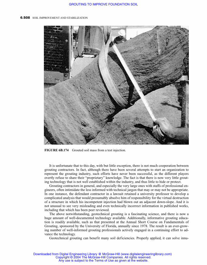
It is unfortunate that to this day, with but little exception, there is not much cooperation betweengrouting contractors. In fact, although there have been several attempts to start an organization torepresent the grouting industry, such efforts have never been successful, as the different playersovertly refuse to share their “proprietary” knowledge. The fact is that there is now very little grout-ing technology that is not well established within the industry, and thus little to hide or protect.
Grouting contractors in general, and especially the very large ones with staffs of professional en-gineers, often intimidate the less informed with technical jargon that may or may not be appropriate.In one instance, the defendant contractor in a lawsuit retained a university professor to develop acomplicated analysis that would presumably absolve him of responsibility for the virtual destructionof a structure in which his incompetent injection had blown out an adjacent down-slope. And it isnot unusual to see very misleading and even technically incorrect information in published works,including that which has been peer reviewed.
The above notwithstanding, geotechnical grouting is a fascinating science, and there is now ahuge amount of well-documented technology available. Additionally, informative grouting educa-tion is readily available, such as that presented at the Annual Short Course on Fundamentals ofGrouting, sponsored by the University of Florida, annually since 1978. The result is an ever-grow-ing number of well-informed grouting professionals actively engaged in a continuing effort to ad-vance the technology.
Geotechnical grouting can benefit many soil deficiencies. Properly applied, it can solve innu-
6.508 SOIL IMPROVEMENT AND STABILIZATION
FIGURE 6B.174 Grouted soil mass from a test injection.
Downloaded from Digital Engineering Library @ McGraw-Hill (www.digitalengineeringlibrary.com)Copyright © 2004 The McGraw-Hill Companies. All rights reserved.
Any use is subject to the Terms of Use as given at the website.
GROUTING TO IMPROVE FOUNDATION SOIL

merable and sometimes vexing problems to the benefit of all involved. Because of the confusionand misinformation promulgated by so many within the industry, enormous opportunity is availableto informed professionals to advance the science. Although it is not possible to cover every detail ofthe many facets of geotechnical grouting in a single chapter such as this, it is the writer’s ferventhope that the reader has become sufficiently informed on the technology, that he will never againbecome confused or intimidated by other grouters and will, rather, become part of the ever-expand-ing group of enlightened grouters. Grouting is a science, and anybody that says otherwise is eitherill informed or a liar.
REFERENCES AND FURTHER READING
ACI 116R-90 (1990). “Cement and Concrete Terminology,” American Concrete Institute, Farmington Hills,Michigan.
ASTM Special Technical Publication 169B (1978). “Significance of Tests and Properties of Concrete and Con-crete-Making Materials,” American Society for Testing and Materials, Philadelphia, Pennsylvania.
Ata, A., and Vipulanandan, C. (1999). “Factors Affecting Mechanical and Creep Properties of Silicate-GroutedSands.” Journal of Geotechnical and Geoenvironmental Engineering, ASCE, Oct.
Boynton, R. and Blacklock, J. (1986). “Lime Slurry Pressure Injection Bulletin,” Bulletin 331. National LimeAssociation, Arlington, Virginia.
Brown, D., and Warner, J., “Compaction Grouting,” Journal of the Soil Mechanics and Foundations Division,ASCE, Vol. 99, No. SM8, Proc. Paper 9908, August 1973, pp. 589–601.
Byle, M. J., and Borden, R. H. (1995). “Verification of Geotechnical Grouting.” GeoInstitute of the AmericanSociety of Civil Engineers, Special Publication No. 57, Oct.
Committee on Grouting of the Geotechnical Engineering Division. (1977). “Slabjacking—State-of-the-Art.”Journal of the Geotechnical Engineering Division, ASCE, Vol. 103, No. GT9, Proc. Paper 13239, Sept.
Deep Foundations Institute. (1993). “Augered Cast-in-Place Piles Manual.” Deep Foundations Institute, Sparta,New Jersey.
Donovan, N. C., Becker, A. M., and Lau, G. Y. (1984). “Liquefaction Mitigation by Site Improvement—A CaseStudy.” Proceedings, Eighth World Conference on Earthquake Engineering, San Francisco, Vol. 1. Engle-wood Cliffs, NJ: Prentice-Hall.
Ehsan, J. (1966). “Geotechnical Design Report.” Phase 2 Storm Drain System Repairs, Century Freeway 07-LA-105-PM 13.7/17.3. California Department of Transportation, May 17.
Gendarme, G. F. (1978). “Report.” Cone Penetrometer Tests, Huntington Harbor, Broadmoor Marina, SunsetBeach, California, May.
Graf, E. D., “Compaction Grouting Technique.” Journal of the Soil Mechanics and Foundations Division, ASCE,Vol 95, No. SM5, Paper 6766, Sept. 1969, pp. 1151–1158.
Graf, T. E., Clough, F. W., and Warner, J. (1982). “Long Term Aging Effects on Chemically Stabilized Soil.” Pro-ceedings, Conference on Grouting in Geotechnical Engineering, New Orleans, February 1982. AmericanSociety of Civil Engineers.
Houlsby, A. C. (1982). “Optimum Water: Cement Ratios for Rock Grouting.” Proceedings, Conference on Grout-ing in Geotechnical Engineering, New Orleans, February, 1982, American Society of Civil Engineers.
Houlsby, A. C., (1990). Construction and Design of Cement Grouting. New York: Wiley.King, J. and Bush, E. (1961). “Symposium on Grouting: Grouting of Granular Materials.” Journal of the Soil
Mechanics and Foundations Division, ASCE, Vol.87, Paper 2791, April.Kravetz, G. A. (1959). Authors closure to paper “Cement and Clay Grouting of Foundations: The Use of Clay in
Pressure Grouting.” Journal of the Soil Mechanics and Foundations Division, ASCE, Vol. 85, SM2,109–114.
Lombardi, G. (1985). “The Role of Cohesion in Cement Grouting of Rock.” Fifteenth Conference on LargeDams, International Commission of Large Dams, Lausanne, Vol. III, pp. 235–261.
McGovern, M. (1996). “Grouting Combination Repairs Sewer Pipe.” Concrete Repair Digest, Vol. 7, No. 2,April/May.
Mehta, P. and Monteiro, P. (1993). Concrete. Second Edition, Englewood Cliffs, NJ: Prentice-Hall.“Recommendations for the Handling of Aromatic Isocyanates.” (1976). International Isocyanate Institute, Inc.,
New York.Rehwoldt, E. B., Matheson, G. M., and Dunscomb, M. H. (1999). “Electrical Explorations.” Civil Engineering,
ASCE, Reston Virginia, October.
6.509GROUTING TO IMPROVE FOUNDATION SOIL
Downloaded from Digital Engineering Library @ McGraw-Hill (www.digitalengineeringlibrary.com)Copyright © 2004 The McGraw-Hill Companies. All rights reserved.
Any use is subject to the Terms of Use as given at the website.
GROUTING TO IMPROVE FOUNDATION SOIL

Shimoda, M., and Ohmori, H. (1982). “Ultra Fine Grouting Materials.” Proceedings, Conference on Grouting inGeotechnical Engineering, New Orleans, February, 1982. American Society of Civil Engineers.
Tattersall, G. H. and Banfill, P. F. (1983). “The Rheology of Fresh Concrete.” London: Pitman.Technical Memorandum No. 3-408. (1956). “Grouting of Foundation Sands and Gravels.” U.S. Army Corps of
Engineers, Waterways Experiment Station, Vicksburg, Mississippi, June, 1995 (Report), January, 1996(Appendix).
Technical Memorandum 646. (1957). “Pressure Grouting.” United States Department of the Interior, Bureau ofReclamation, Design and Construction Division, Denver, June.
Vettel, J. J., and Clark, D. W. (1996). “Compaction Grouting Review, Century Freeway.” San Diego, CA: AgraEarth & Environmental.
Warner, J., et al. (1992). “Recent Advances in Compaction Grouting Technology.” Proceedings, Grouting, SoilImprovement and Geosynthetics, ASCE, New Orleans, Geotechnical Special Publication No. 30, Feb.
Warner, J. (1972). “Strength Properties of Chemically Solidified Soils.” Journal of the Soil Mechanics andFoundation Engineering Division, ASCE, Vol.98, No. SM11, Proc. Paper 9332, November, pp.1163–1185.
Warner, J., and Brown, D. R. (1974). “Planning and Performing Compaction Grouting.” Journal of the Geotech-nical Engineering Division, ASCE, Vol. 100, No. GT6, Proc. Paper 10606, June, pp 653–666.
Warner, J., Schmidt, N., Reed, J., Shepardson, D., Lamb, R., and Wong, S. (1992). “Recent Advances in Com-paction Grouting Technology.” Proceedings, Grouting, Soil Improvement and Geosynthetics, GT Division,ASCE, New Orleans, Louisiana, Feb.
Weaver, K. (1991). Dam Foundation Grouting. New York: American Society of Civil Engineers.Xanthakos, P., Abramson, L., and Bruce, D., (1994). Ground Control and Improvement. New York: Wiley.
6.510 SOIL IMPROVEMENT AND STABILIZATION
Downloaded from Digital Engineering Library @ McGraw-Hill (www.digitalengineeringlibrary.com)Copyright © 2004 The McGraw-Hill Companies. All rights reserved.
Any use is subject to the Terms of Use as given at the website.
GROUTING TO IMPROVE FOUNDATION SOIL


