Embed Size (px)
Citation preview

Data Sheet
Aluminum electrolytic capacitors Alu-X product lines
Single-ended capacitors
Series/Type: B41827, B43827Date: August 2008
© EPCOS AG 2008. Reproduction, publication and dissemination of this publication and the infor-mation contained therein without EPCOS’ prior express consent is prohibited.

Single-ended capacitors B41827, B43827Standard series – 85 °C
2 08/08Please read Cautions and warnings and Important notes at the end of this document.
General-purpose grade capacitors
Applications
■ For general-purpose applications in the entertainment industry■ Semi-professional to professional application range■ For filtering, coupling and pulse circuits
Features
■ Miniaturized dimensions■ RoHS-compatible■ Load life of 2000 h at 85 °C
Construction
■ Radial leads■ Charge-discharge proof, polar■ Aluminum case with insulating sleeve■ Minus pole marking on the insulating sleeve■ Case with safety vent from diameter 8 mm
Delivery mode
■ Bulk■ Taped, Ammo pack■ Cut■ Kinked
Single-ended capacitors B41827, B43827Standard series – 85 °C
Single-ended capacitors B41827, B43827Standard series – 85 °C
3 08/08Please read Cautions and warnings and Important notes at the end of this document.
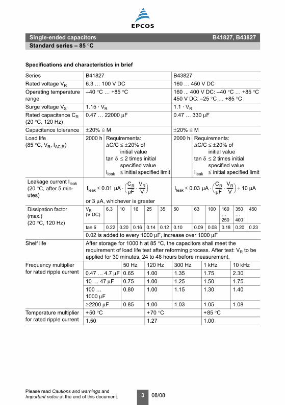
Specifications and characteristics in brief
Series B41827 B43827Rated voltage VR 6.3 … 100 V DC 160 … 450 V DCOperating temperature range
–40 °C … +85 °C 160 ... 400 V DC: –40 °C … +85 °C450 V DC: –25 °C … +85 °C
Surge voltage VS 1.15 · VR 1.1 · VR
Rated capacitance CR(20 °C, 120 Hz)
0.47 … 22000 µF 0.47 … 330 µF
Capacitance tolerance ±20% M ±20% MLoad life(85 °C, VR, IAC,R)
2000 h Requirements:∆C/C ≤ ±20% of
initial valuetan δ ≤ 2 times initial
specified valueIleak ≤ initial specified limit
2000 h Requirements:∆C/C ≤ ±20% of
initial valuetan δ ≤ 2 times initial
specified valueIleak ≤ initial specified limit
Leakage current Ileak(20 °C, after 5 min-utes)
or 3 µA, whichever is greaterDissipation factor (max.)(20 °C, 120 Hz)
VR(V DC)
6.3 10 16 25 35 50 63 100 160 … 250
350 … 400
450
tan δ 0.22 0.20 0.16 0.14 0.12 0.10 0.09 0.08 0.18 0.20 0.23
0.02 is added to every 1000 µF, increase over 1000 µFShelf life After storage for 1000 h at 85 °C, the capacitors shall meet the
requirement of load life test after reforming process. After test: VR to be applied for 30 minutes, 24 to 48 hours before measurement.
Frequency multiplierfor rated ripple current
50 Hz 120 Hz 300 Hz 1 kHz 10 kHz0.47 … 4.7 µF 0.65 1.00 1.35 1.75 2.3010 … 47 µF 0.75 1.00 1.25 1.50 1.75100 … 1000 µF
0.80 1.00 1.15 1.30 1.40
≥2200 µF 0.85 1.00 1.03 1.05 1.08Temperature multiplierfor rated ripple current
+50 °C +70 °C +85 °C1.50 1.27 1.00
Ileak 0.01 µACRµF-------
VRV
-------⋅⎝ ⎠⎛ ⎞⋅≤ Ileak 0.03 µA
CRµF-------
VRV
-------⋅⎝ ⎠⎛ ⎞ 10 µA+⋅≤
Single-ended capacitors B41827, B43827Standard series – 85 °C
4 08/08Please read Cautions and warnings and Important notes at the end of this document.
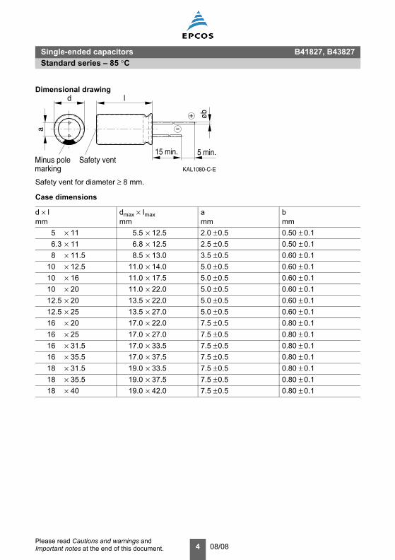
Dimensional drawing
Safety vent for diameter ≥ 8 mm.
Case dimensions
d × l mm
dmax × Imaxmm
amm
bmm
5 × 11 5.5 × 12.5 2.0 ±0.5 0.50 ± 0.16.3 × 11 6.8 × 12.5 2.5 ±0.5 0.50 ± 0.18 × 11.5 8.5 × 13.0 3.5 ±0.5 0.60 ± 0.1
10 × 12.5 11.0 × 14.0 5.0 ±0.5 0.60 ± 0.110 × 16 11.0 × 17.5 5.0 ±0.5 0.60 ± 0.110 × 20 11.0 × 22.0 5.0 ±0.5 0.60 ± 0.112.5 × 20 13.5 × 22.0 5.0 ±0.5 0.60 ± 0.112.5 × 25 13.5 × 27.0 5.0 ±0.5 0.60 ± 0.116 × 20 17.0 × 22.0 7.5 ±0.5 0.80 ± 0.116 × 25 17.0 × 27.0 7.5 ±0.5 0.80 ± 0.116 × 31.5 17.0 × 33.5 7.5 ±0.5 0.80 ± 0.116 × 35.5 17.0 × 37.5 7.5 ±0.5 0.80 ± 0.118 × 31.5 19.0 × 33.5 7.5 ±0.5 0.80 ± 0.118 × 35.5 19.0 × 37.5 7.5 ±0.5 0.80 ± 0.118 × 40 19.0 × 42.0 7.5 ±0.5 0.80 ± 0.1
KAL1080-C-E
a
d
marking
15 min. 5 min.
-
+ øb
Minus pole Safety vent
l
Single-ended capacitors B41827, B43827Standard series – 85 °C
5 08/08Please read Cautions and warnings and Important notes at the end of this document.
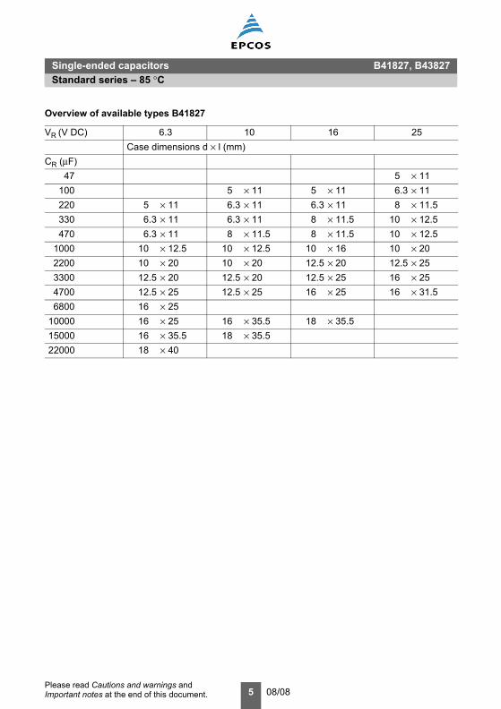
Overview of available types B41827
VR (V DC) 6.3 10 16 25Case dimensions d × l (mm)
CR (µF)47 5 × 11
100 5 × 11 5 × 11 6.3 × 11220 5 × 11 6.3 × 11 6.3 × 11 8 × 11.5330 6.3 × 11 6.3 × 11 8 × 11.5 10 × 12.5470 6.3 × 11 8 × 11.5 8 × 11.5 10 × 12.5
1000 10 × 12.5 10 × 12.5 10 × 16 10 × 202200 10 × 20 10 × 20 12.5 × 20 12.5 × 253300 12.5 × 20 12.5 × 20 12.5 × 25 16 × 254700 12.5 × 25 12.5 × 25 16 × 25 16 × 31.56800 16 × 25
10000 16 × 25 16 × 35.5 18 × 35.515000 16 × 35.5 18 × 35.522000 18 × 40

Single-ended capacitors B41827, B43827Standard series – 85 °C
6 08/08Please read Cautions and warnings and Important notes at the end of this document.
Overview of available types B41827
VR (V DC) 35 50 63 100Case dimensions d × l (mm)
CR (µF)0.47 5 × 111.0 5 × 112.2 5 × 113.3 5 × 114.7 5 × 11
10 5 × 11 5 × 11 6.3 × 1122 5 × 11 6.3 × 11 8 × 11.533 5 × 11 5 × 11 6.3 × 11 10 × 12.547 5 × 11 6.3 × 11 6.3 × 11 10 × 12.5
100 6.3 × 11 8 × 11.5 10 × 12.5 10 × 20220 10 × 12.5 10 × 12.5 10 × 20 12.5 × 25330 10 × 12.5 10 × 16 12.5 × 20 16 × 25470 10 × 16 10 × 20 12.5 × 25 16 × 31.5
1000 12.5 × 25 16 × 20 16 × 31.5 18 × 402200 16 × 25 16 × 31.53300 16 × 31.54700 18 × 35.5

Single-ended capacitors B41827, B43827Standard series – 85 °C
7 08/08Please read Cautions and warnings and Important notes at the end of this document.
Overview of available types B43827
VR (V DC) 160 200 250Case dimensions d × l (mm)
CR (µF)0.47 5 × 11 5 × 111.0 5 × 11 5 × 112.2 5 × 11 6.3 × 113.3 6.3 × 11 6.3 × 11 6.3 × 114.7 6.3 × 11 8 × 11.5 8 × 11.5
10 8 × 11.5 10 × 12.5 10 × 12.522 10 × 16 10 × 20 10 × 2033 10 × 20 12.5 × 20 12.5 × 2547 12.5 × 25 12.5 × 20 12.5 × 25
100 16 × 25 16 × 25 16 × 31.5220 16 × 35.5 18 × 35.5330 18 × 35.5
VR (V DC) 350 400 450Case dimensions d × l (mm)
CR (µF)0.47 6.3 × 11 8 × 11.51.0 6.3 × 11 6.3 × 11 8 × 11.52.2 8 × 11.5 8 × 11.5 10 × 12.53.3 10 × 12.5 10 × 12.5 10 × 164.7 10 × 12.5 10 × 16 10 × 20
10 10 × 20 12.5 × 20 12.5 × 2022 12.5 × 25 16 × 25 16 × 2533 16 × 25 16 × 25 16 × 31.547 16 × 35.5 16 × 35.5 18 × 40
100 18 × 40

Single-ended capacitors B41827, B43827Standard series – 85 °C
8 08/08Please read Cautions and warnings and Important notes at the end of this document.
*** = Version000 = for standard leads, bulk001 = for kinked leads, bulk002 = for cut leads, bulk016 = for taped leads, Ammo pack, lead spacing F = 2.0 mm007 = for taped leads, Ammo pack, lead spacing F = 2.5 mm006 = for taped leads, Ammo pack, lead spacing F = 3.5 mm008 = for taped leads, Ammo pack, lead spacing F = 5.0 mm, d ≤ 10 mm
Technical data and ordering codes B41827
VR
V DC
CR120 Hz20 °CµF
Casedimensionsd × lmm
IAC,R120 Hz85 °CmA
Ordering code(composition see below)
6.3 220 5 × 11 200 B41827A2227M***330 6.3 × 11 270 B41827A2337M***470 6.3 × 11 321 B41827A2477M***
1000 10 × 12.5 542 B41827A2108M***2200 10 × 20 1005 B41827A2228M***3300 12.5 × 20 1195 B41827A2338M***4700 12.5 × 25 1560 B41827A2478M***6800 16 × 25 1925 B41827A2688M***
10000 16 × 25 2360 B41827A2109M***15000 16 × 35.5 2855 B41827A2159M***22000 18 × 40 3345 B41827A2229M***
10 100 5 × 11 130 B41827A3107M***220 6.3 × 11 280 B41827A3227M***330 6.3 × 11 290 B41827A3337M***470 8 × 11.5 385 B41827A3477M***
1000 10 × 12.5 650 B41827A3108M***2200 10 × 20 1082 B41827A3228M***3300 12.5 × 20 1436 B41827A3338M***4700 12.5 × 25 1783 B41827A3478M***
10000 16 × 35.5 2700 B41827A3109M***15000 18 × 35.5 3100 B41827A3159M***
16 100 5 × 11 160 B41827A4107M***220 6.3 × 11 261 B41827A4227M***330 8 × 11.5 373 B41827A4337M***470 8 × 11.5 446 B41827A4477M***
1000 10 × 16 790 B41827A4108M***2200 12.5 × 20 1310 B41827A4228M***3300 12.5 × 25 1695 B41827A4338M***4700 16 × 25 2100 B41827A4478M***
10000 18 × 35.5 2980 B41827A4109M***

Single-ended capacitors B41827, B43827Standard series – 85 °C
9 08/08Please read Cautions and warnings and Important notes at the end of this document.
*** = Version000 = for standard leads, bulk001 = for kinked leads, bulk002 = for cut leads, bulk016 = for taped leads, Ammo pack, lead spacing F = 2.0 mm007 = for taped leads, Ammo pack, lead spacing F = 2.5 mm006 = for taped leads, Ammo pack, lead spacing F = 3.5 mm008 = for taped leads, Ammo pack, lead spacing F = 5.0 mm, d ≤ 10 mm
Technical data and ordering codes B41827
VR
V DC
CR120 Hz20 °CµF
Casedimensionsd × lmm
IAC,R120 Hz85 °CmA
Ordering code(composition see below)
25 47 5 × 11 108 B41827A5476M***100 6.3 × 11 192 B41827A5107M***220 8 × 11.5 335 B41827A5227M***330 10 × 12.5 446 B41827A5337M***470 10 × 12.5 547 B41827A5477M***
1000 10 × 20 962 B41827A5108M***2200 12.5 × 25 1560 B41827A5228M***3300 16 × 25 1985 B41827A5338M***4700 16 × 31.5 2455 B41827A5478M***
35 33 5 × 11 102 B41827A7336M***47 5 × 11 130 B41827A7476M***
100 6.3 × 11 212 B41827A7107M***220 10 × 12.5 390 B41827A7227M***330 10 × 12.5 495 B41827A7337M***470 10 × 16 652 B41827A7477M***
1000 12.5 × 25 1158 B41827A7108M***2200 16 × 25 1810 B41827A7228M***3300 16 × 31.5 2293 B41827A7338M***4700 18 × 35.5 2710 B41827A7478M***
50 10 5 × 11 58 B41827A6106M***22 5 × 11 85 B41827A6226M***33 5 × 11 117 B41827A6336M***47 6.3 × 11 155 B41827A6476M***
100 8 × 11.5 260 B41827A6107M***220 10 × 12.5 430 B41827A6227M***330 10 × 16 510 B41827A6337M***470 10 × 20 700 B41827A6477M***
1000 16 × 20 1100 B41827A6108M***2200 16 × 31.5 1540 B41827A6228M***

Single-ended capacitors B41827, B43827Standard series – 85 °C
10 08/08Please read Cautions and warnings and Important notes at the end of this document.
*** = Version000 = for standard leads, bulk001 = for kinked leads, bulk002 = for cut leads, bulk016 = for taped leads, Ammo pack, lead spacing F = 2.0 mm007 = for taped leads, Ammo pack, lead spacing F = 2.5 mm006 = for taped leads, Ammo pack, lead spacing F = 3.5 mm008 = for taped leads, Ammo pack, lead spacing F = 5.0 mm, d ≤ 10 mm
Technical data and ordering codes B41827
VR
V DC
CR120 Hz20 °CµF
Casedimensionsd × lmm
IAC,R120 Hz85 °CmA
Ordering code(composition see below)
63 10 5 × 11 60 B41827A8106M***22 6.3 × 11 100 B41827A8226M***33 6.3 × 11 140 B41827A8336M***47 6.3 × 11 170 B41827A8476M***
100 10 × 12.5 300 B41827A8107M***220 10 × 20 475 B41827A8227M***330 12.5 × 20 710 B41827A8337M***470 12.5 × 25 900 B41827A8477M***
1000 16 × 31.5 1300 B41827A8108M***100 0.47 5 × 11 13 B41827A9474M***
1.0 5 × 11 20 B41827A9105M***2.2 5 × 11 29 B41827A9225M***3.3 5 × 11 36 B41827A9335M***4.7 5 × 11 43 B41827A9475M***
10 6.3 × 11 75 B41827A9106M***22 8 × 11.5 130 B41827A9226M***33 10 × 12.5 180 B41827A9336M***47 10 × 12.5 230 B41827A9476M***
100 10 × 20 370 B41827A9107M***220 12.5 × 25 620 B41827A9227M***330 16 × 25 760 B41827A9337M***470 16 × 31.5 1000 B41827A9477M***
1000 18 × 40 1380 B41827A9108M***

Single-ended capacitors B41827, B43827Standard series – 85 °C
11 08/08Please read Cautions and warnings and Important notes at the end of this document.
*** = Version000 = for standard leads, bulk001 = for kinked leads, bulk002 = for cut leads, bulk016 = for taped leads, Ammo pack, lead spacing F = 2.0 mm007 = for taped leads, Ammo pack, lead spacing F = 2.5 mm006 = for taped leads, Ammo pack, lead spacing F = 3.5 mm 008 = for taped leads, Ammo pack, lead spacing F = 5.0 mm, d ≤ 10 mm
Technical data and ordering codes B43827
VR
V DC
CR120 Hz20 °CµF
Casedimensionsd × lmm
IAC,R120 Hz85 °CmA
Ordering code(composition see below)
160 0.47 5 × 11 15 B43827A1474M***1.0 5 × 11 22 B43827A1105M***2.2 5 × 11 33 B43827A1225M***3.3 6.3 × 11 40 B43827A1335M***4.7 6.3 × 11 49 B43827A1475M***
10 8 × 11.5 80 B43827A1106M***22 10 × 16 152 B43827A1226M***33 10 × 20 203 B43827A1336M***47 12.5 × 25 268 B43827A1476M***
100 16 × 25 423 B43827A1107M***220 16 × 35.5 786 B43827A1227M***330 18 × 35.5 945 B43827A1337M***
200 3.3 6.3 × 11 40 B43827A2335M***4.7 8 × 11.5 56 B43827A2475M***
10 10 × 12.5 95 B43827A2106M***22 10 × 20 170 B43827A2226M***33 12.5 × 20 225 B43827A2336M***47 12.5 × 20 267 B43827A2476M***
100 16 × 25 490 B43827A2107M***220 18 × 35.5 815 B43827A2227M***
250 0.47 5 × 11 15 B43827F2474M***1.0 5 × 11 22 B43827F2105M***2.2 6.3 × 11 33 B43827F2225M***3.3 6.3 × 11 47 B43827F2335M***4.7 8 × 11.5 56 B43827F2475M***
10 10 × 12.5 103 B43827F2106M***22 10 × 20 185 B43827F2226M***33 12.5 × 25 225 B43827F2336M***47 12.5 × 25 268 B43827F2476M***
100 16 × 31.5 525 B43827F2107M***

Single-ended capacitors B41827, B43827Standard series – 85 °C
12 08/08Please read Cautions and warnings and Important notes at the end of this document.
*** = Version000 = for standard leads, bulk001 = for kinked leads, bulk002 = for cut leads, bulk016 = for taped leads, Ammo pack, lead spacing F = 2.0 mm007 = for taped leads, Ammo pack, lead spacing F = 2.5 mm006 = for taped leads, Ammo pack, lead spacing F = 3.5 mm008 = for taped leads, Ammo pack, lead spacing F = 5.0 mm, d ≤ 10 mm
Technical data and ordering codes B43827
VR
V DC
CR120 Hz20 °CµF
Casedimensionsd × lmm
IAC,R120 Hz85 °CmA
Ordering code(composition see below)
350 1.0 6.3 × 11 22 B43827A4105M***2.2 8 × 11.5 38 B43827A4225M***3.3 10 × 12.5 54 B43827A4335M***4.7 10 × 12.5 65 B43827A4475M***
10 10 × 20 115 B43827A4106M***22 12.5 × 25 185 B43827A4226M***33 16 × 25 276 B43827A4336M***47 16 × 35.5 334 B43827A4476M***
100 18 × 40 510 B43827A4107M***400 0.47 6.3 × 11 15 B43827A9474M***
1.0 6.3 × 11 23 B43827A9105M***2.2 8 × 11.5 40 B43827A9225M***3.3 10 × 12.5 55 B43827A9335M***4.7 10 × 16 67 B43827A9475M***
10 12.5 × 20 118 B43827A9106M***22 16 × 25 200 B43827A9226M***33 16 × 25 280 B43827A9336M***47 16 × 35.5 362 B43827A9476M***
450 0.47 8 × 11.5 18 B43827A5474M***1.0 8 × 11.5 24 B43827A5105M***2.2 10 × 12.5 36 B43827A5225M***3.3 10 × 16 44 B43827A5335M***4.7 10 × 20 56 B43827A5475M***
10 12.5 × 20 95 B43827A5106M***22 16 × 25 170 B43827A5226M***33 16 × 31.5 235 B43827A5336M***47 18 × 40 302 B43827A5476M***
Single-ended capacitors B41827, B43827Taping, packing and lead configurations
13 08/08Please read Cautions and warnings and Important notes at the end of this document.
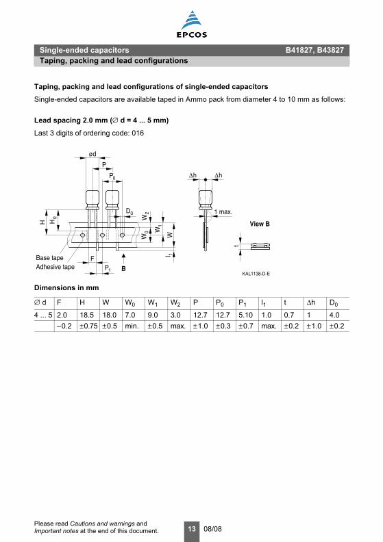
Taping, packing and lead configurations of single-ended capacitors
Single-ended capacitors are available taped in Ammo pack from diameter 4 to 10 mm as follows:
Lead spacing 2.0 mm (∅ d = 4 ... 5 mm)
Last 3 digits of ordering code: 016
Dimensions in mm
∅ d F H W W0 W1 W2 P P0 P1 l1 t ∆h D0
4 ... 5 2.0 18.5 18.0 7.0 9.0 3.0 12.7 12.7 5.10 1.0 0.7 1 4.0–0.2 ±0.75 ±0.5 min. ±0.5 max. ±1.0 ±0.3 ±0.7 max. ±0.2 ±1.0 ±0.2
Adhesive tapeBase tape F
B
H
ød
PW
t
KAL1138-D-E
1 max.
View B
P0
0H
P1
D0
W0
W2
W1
1lh∆h ∆
Single-ended capacitors B41827, B43827Taping, packing and lead configurations

Single-ended capacitors B41827, B43827Taping, packing and lead configurations
14 08/08Please read Cautions and warnings and Important notes at the end of this document.
Lead spacing 2.5 mm (∅ d = 4 ... 6.3 mm)
Last 3 digits of ordering code: 007
Lead spacing 3.5 mm (∅ d = 8 mm)
Last 3 digits of ordering code: 006
Dimensions in mm
∅ d F H H0 W W0 W1 W2 P P0 P1 l1 t ∆h D0
4 ... 6.3 2.5 18.5 16.0 18.0 7.0 9.0 3.0 12.7 12.7 5.10 1.0 0.7 0 4.0Tolerance –0.2 ±0.75 ±0.5 ±0.5 min. ±0.5 max. ±1.0 ±0.3 ±0.7 max. ±0.2 ±1.0 ±0.2
Dimensions in mm
∅ d F H W W0 W1 W2 P P0 P1 l1 t ∆h D0
8 3.5 18.5 18.0 10 9.0 3.0 12.7 12.7 5.10 1.0 0.7 1 4.0Tolerance ±0.5 ±0.75 ±0.5 min. ±0.5 max. ±1.0 ±0.3 ±0.7 max. ±0.2 max. ±0.2
Adhesive tapeBase tape F
B
H
ød
P
W
tKAL1074-3-E
1 max.
View B
P0
0H
P1
D0
W0
W2
W1
1l
h∆h ∆
Adhesive tapeBase tape F
B
H
ød
P
W
t
KAL1138-D-E
1 max.
View B
P0
0H
P1
D0
W0
W2
W1
1l
h∆h ∆

Single-ended capacitors B41827, B43827Taping, packing and lead configurations
15 08/08Please read Cautions and warnings and Important notes at the end of this document.
Lead spacing 5.0 mm (∅ d = 4 ... 8 mm)
Last 3 digits of ordering code: 008
Lead spacing 5.0 mm (∅ d = 10 mm)
Last 3 digits of ordering code: 008
Taping is available up to dimensions d × l = 10 × 20 mm. For ∅ 12.5, 16 and 18 mm taping is notavailable.
Dimensions in mm
∅ d F H H0 W W0 W1 W2 P P0 P1 L1 t ∆h D0
4 ... 6.3 5.0 18.5 16 18.0 7.0 9.0 3.0 12.7 12.7 3.85 1.0 0.6 2.0 4.08 5.0 18.5 16 18.0 10 9.0 3.0 12.7 12.7 3.85 1.0 0.6 2.0 4.010 5.0 18.5 – 18.0 12.5 9.0 3.0 12.7 12.7 3.85 1.0 0.6 2.0 4.0Tolerance +0.6
–0.2±0.75 ±0.5 +1.0
–0.5+1.0–0
±0.5 max. ±0.5 ±0.3 ±0.7 max. +0.3–0.2
max. ±0.2
Adhesive tapeBase tape F
B
H
ød
P
W
KAL1075-B-E
t
1 max.
View B
0P
P1
D0
H0 1
W
W2
W0
1l
h∆ h∆
Adhesive tapeBase tape F
B
H
ød
P
W
KAL1076-J-E
t
1 max.
View B
P0
P1
D0
W0
W2
W1
1l
h∆ h∆
Single-ended capacitors B41827, B43827Taping, packing and lead configurations
16 08/08Please read Cautions and warnings and Important notes at the end of this document.
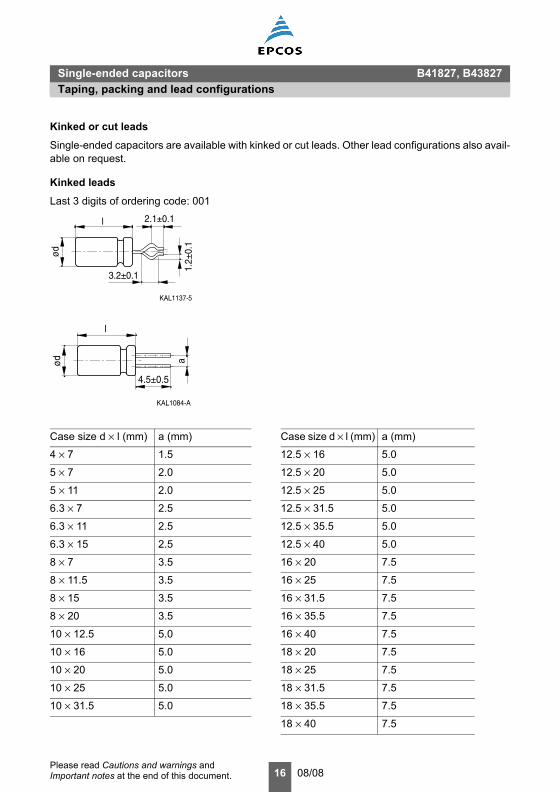
Kinked or cut leads
Single-ended capacitors are available with kinked or cut leads. Other lead configurations also avail-able on request.
Kinked leads
Last 3 digits of ordering code: 001
Case size d × l (mm) a (mm) Case size d × l (mm) a (mm)
4 × 7 1.5 12.5 × 16 5.0
5 × 7 2.0 12.5 × 20 5.0
5 × 11 2.0 12.5 × 25 5.0
6.3 × 7 2.5 12.5 × 31.5 5.0
6.3 × 11 2.5 12.5 × 35.5 5.0
6.3 × 15 2.5 12.5 × 40 5.0
8 × 7 3.5 16 × 20 7.5
8 × 11.5 3.5 16 × 25 7.5
8 × 15 3.5 16 × 31.5 7.5
8 × 20 3.5 16 × 35.5 7.5
10 × 12.5 5.0 16 × 40 7.5
10 × 16 5.0 18 × 20 7.5
10 × 20 5.0 18 × 25 7.5
10 × 25 5.0 18 × 31.5 7.5
10 × 31.5 5.0 18 × 35.5 7.5
18 × 40 7.5
ød
3.2±0.1
KAL1137-5
1.2±
0.1
2.1±0.1l
4.5±0.5
ød
KAL1084-A
a
l
Single-ended capacitors B41827, B43827Taping, packing and lead configurations
17 08/08Please read Cautions and warnings and Important notes at the end of this document.
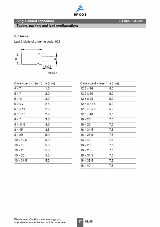
Cut leads
Last 3 digits of ordering code: 002
Case size d × l (mm) a (mm) Case size d × l (mm) a (mm)
4 × 7 1.5 12.5 × 16 5.0
5 × 7 2.0 12.5 × 20 5.0
5 × 11 2.0 12.5 × 25 5.0
6.3 × 7 2.5 12.5 × 31.5 5.0
6.3 × 11 2.5 12.5 × 35.5 5.0
6.3 × 15 2.5 12.5 × 40 5.0
8 × 7 3.5 16 × 20 7.5
8 × 11.5 3.5 16 × 25 7.5
8 × 15 3.5 16 × 31.5 7.5
8 × 20 5.0 16 × 35.5 7.5
10 × 12.5 5.0 16 × 40 7.5
10 × 16 5.0 18 × 20 7.5
10 × 20 5.0 18 × 25 7.5
10 × 25 5.0 18 × 31.5 7.5
10 × 31.5 5.0 18 × 35.5 7.5
18 × 40 7.5
ød
KAL1086-R
a
4.5±0.5
l

18 08/08Please read Cautions and warnings and Important notes at the end of this document.
General
Also see “Important notes” on page 20.1 Aluminum electrolytic capacitors have a bi-polar structure. This is marked on the body of the
capacitor. A capacitor must not be mounted with reversed polarity. The application of an ACor reverse voltage may cause a short circuit or damage the capacitor. Bi-polar capacitorsmust not be used in AC applications, where the polarity may be reversed in the circuits or isunknown.
2 The DC voltage applied to the capacitor terminal must not exceed its rated operating voltage,as this will result in a rapid increase of the leakage current and may damage the capacitor. Itis recommended to operate the capacitor at 70–80% of its rated voltage to optimize its serv-ice life.
3 The ripple current applied to the capacitor must be within the permitted range. An excessiveripple current leads to impaired electrical properties and may damage the capacitor. Note thatthe sum of the peak values of the ripple voltage and the DC operating voltage must not ex-ceed the rated DC voltage.
4 Capacitors must be used within their permitted range of operating temperature. Operation atroom temperature optimizes their service life.
5 Capacitors with case diameter ≥8 mm are equipped with a safety vent. In capacitors fittedwith a lead or soldering lug, the safety vent is usually located at the base of the case. It needssufficient space around it to operate optimally. The following dimensions are recommended:for case diameter d = 8 to 16 mm, more than 2 mm; for d =18 to 35 mm, more than 3 mm;and for d = 42 mm or more, more than 5 mm.
6 Capacitors should not be mounted with the safety vent face down on the board. Do not locateany wire or copper trace near the safety vent. Do not reverse the voltage, as this may resultin excess pressure and the leakage of electrolyte.
7 Gas is released through the safety vent when the pressure inside the capacitor is too high. Agaseous liquid around the safety vent does not indicate a leakage of electrolyte.
8 The capacitor should be stored under conditions of normal temperature and in a non-acid,non-alkali environment of normal humidity. Exposure to high temperatures, for example un-der direct sunlight, will reduce its operating life. If the capacitor is stored in an environmentcontaining acids or alkalis, the solderability of the leads may be affected.
9 The leakage current of an aluminum electrolytic capacitor may increase after a long periodof storage. After such storage, the capacitor must be aged by applying the rated operatingvoltage for 6–8 hours before use.
10 Manual soldering:a Soldering must be performed within the specified conditions.
Bit temperature: 350 °C; application time of soldering iron: 3 seconds.b Ensure that the soldering iron does not touch any part of the capacitor body.
Cautions and warnings

Cautions and warnings
19 08/08Please read Cautions and warnings and Important notes at the end of this document.
11 Do not apply excessive force to the leads and terminals. Do not move the capacitor after sol-dering it onto the PC board and do not carry the PC board by gripping the capacitor. Observethe following rules to prevent undue stress to the capacitor:a Do not tilt or bend the capacitor after soldering.b Ensure that the terminal spacing matches the corresponding hole spacing on the PC
board.12 The aluminum case is not insulated from the cathode. Do not place a conductor under the
aluminum capacitors on the PC board as this may cause a short circuit. The case and top ofcapacitors used in switched mode power supplies have a high-voltage-resistant heat shrinksleeve to ensure safe usage.
13 The leads of capacitors with a case diameter exceeding 14 mm cannot be used for fixing.

Important notes
20 08/08
Important notesThe following applies to all products named in this publication:1. Some parts of this publication contain statements about the suitability of our products for
certain areas of application. These statements are based on our knowledge of typicalrequirements that are often placed on our products in the areas of application concerned. Wenevertheless expressly point out that such statements cannot be regarded as bindingstatements about the suitability of our products for a particular customer application. Asa rule, EPCOS is either unfamiliar with individual customer applications or less familiar with themthan the customers themselves. For these reasons, it is always ultimately incumbent on thecustomer to check and decide whether an EPCOS product with the properties described in theproduct specification is suitable for use in a particular customer application.
2. We also point out that in individual cases, a malfunction of electronic components or failurebefore the end of their usual service life cannot be completely ruled out in the current stateof the art, even if they are operated as specified. In customer applications requiring a veryhigh level of operational safety and especially in customer applications in which the malfunctionor failure of an electronic component could endanger human life or health (e.g. in accidentprevention or life-saving systems), it must therefore be ensured by means of suitable design ofthe customer application or other action taken by the customer (e.g. installation of protectivecircuitry or redundancy) that no injury or damage is sustained by third parties in the event ofmalfunction or failure of an electronic component.
3. The warnings, cautions and product-specific notes must be observed.4. In order to satisfy certain technical requirements, some of the products described in this
publication may contain substances subject to restrictions in certain jurisdictions (e.g.because they are classed as hazardous). Useful information on this will be found in ourMaterial Data Sheets on the Internet (www.epcos.com/material). Should you have any moredetailed questions, please contact our sales offices.
5. We constantly strive to improve our products. Consequently, the products described in thispublication may change from time to time. The same is true of the corresponding productspecifications. Please check therefore to what extent product descriptions and specificationscontained in this publication are still applicable before or when you place an order.We also reserve the right to discontinue production and delivery of products. Consequently,we cannot guarantee that all products named in this publication will always be available. Theaforementioned does not apply in case of individual agreements deviating from the foregoing forcustomer-specific products.
6. Unless otherwise agreed in individual contracts, all orders are subject to the current versionof the “General Terms of Delivery for Products and Services in the Electrical Industry”published by the German Electrical and Electronics Industry Association (ZVEI).
7. The trade names EPCOS, BAOKE, Alu-X, CeraDiode, CSSP, CTVS, DSSP, MiniBlue, MKK,MLSC, MotorCap, PCC, PhaseCap, PhaseMod, SIFERRIT, SIFI, SIKOREL, SilverCap,SIMDAD, SIMID, SineFormer, SIOV, SIP5D, SIP5K, ThermoFuse, WindCap are trademarksregistered or pending in Europe and in other countries. Further information will be found onthe Internet at www.epcos.com/trademarks.


