Embed Size (px)
Citation preview

Table of Content
Safety Precautions and Procedures………………2
General Description………………………………2
Electric symbol …………………………………4
Function panel ……………………………………5
Operations Description……………………………5
Panel Description………………………………11
Technical Specifications…………………………17
Maintenance ……………………………………20
Accessories Enclosure…………………………20
1
I 、 Safety Precautions and
Procedures This serial instruments are designed according with
relevant clauses of IEC1010, before using, please read the following items carefully:
Before using, please read this " user's manual "※
carefully.
Should check and confirm there is not damage in the※ instrument, the insulating barrier of test lead is intact before using.
While holding the test lead, should pay special attention※ not to hand exceeding the plastic of the testing needle
2

root is protruding, otherwise have danger of shocking by electricity.
Before opening the back cover, must pull out the test※ lead; After closing the back cover and screwing the screw on, could carry on measurement, otherwise have danger of being shocked by electricity.
In measure course, disconnect instrument input and※
then rotate function / range switch.
never input signal electronic voltage exceeding the※
limited value to avoid electronic shock or damaging
the instrument.
the potential difference between the measurement※
public terminal COM and earth can’t exceed 1000V to
avoid electric short or damage the instrument.
pay attention if the tested voltage is over DC 60V and※
AC 42V to avoid electric shock
if there have a symbol ※ on the LCD display, it
indicates low battery. Replace the battery to ensure
measurement accuracy.
※For the fuse, it must be replaced with an identical
model if necessary.For the concrete
specification,please see the clause of maintenance or
label on the instrument board.
3

II、 General Description6500 series manual measuring-range digital
multimeter designs excellent,the appearance is novel and
natural.The large liquid crystal screen dresses up Li's
background light clearly to cause the demonstration to be
artistic.Non- contact alternating current examination
function (namely NCV examination function) can let you
be able fast to judge the object whether has the alternating
current or not in the case of not using test pencil, not using
the test lead and not contacting the object .It brings
enormous convenience for your work. This series digital
multitester includes models HD6501, 6505, 6508 (3 1/2),
6503, (4 1/2) and so on. The function is complete and it is
easy to operate. Besides the triode test and NCV
examination, all measurements are surveyed by the
multimeter lower four test inputs jack,namely use the test
lead to test.Facilitates your operation and strengthen the
security. PTC temperature sensing component is
connected within the V jack input terminus, which has
fully protected the key part of the multimeter --Function /
range switch and improved security and lengthened the
use life-span greatly.
4

Function form:Item 6501 6503 6505 6508
DC Voltage √ √ √ √AC Voltage √ √ √ √DC Current √ √ √ √AC Current √ √ √ √Resistance √ √ √ √Capacitance √ √ √Frequency √ √Temperature √
Diode√ √ √ √
Continuity√ √ √ √
NCV √ √ √ √
Backlight √ √ √ √
Data hold √ √ √ √
Power Off √ √ √ √
Technological characteristicDisplay:The large screen liquid crystal display: visual area 61*35mm, word high 27mm.Max display:1999 (3 1/2),19999 (4 1/2). Automatic polarity display, range exceeding instruction and changing the battery instruction. The beautiful background light of little consumption, go out automatically in several seconds.Measurement:Low power consumption CMOS double integration, A/D transform integrated circuit, auto zero calibrationDC basic precision:(3 1/2)、(4 1/2)。
5

Data Hold functionFull range over loading protecting functionPower Supply:Power supply: one 9V battery (NEDA1604, 6F22 type or equivalently type)Automatic shut-down function, start the machine,power off automatically in about 15 minutesExternal dimension: 182×84×36mmComplete instrument weight: about 247g (include the battery).Environment condition:Working temperature: 0~40℃the relative humidity: < 85%Store temperature: -10~50℃ The relative humidity: < 85%Guarantee the temperature of the precision:23±5℃ The relative humidity < 75%
III、Electronic Symbol
DC
AC
Diode
Buzzer
Low battery
Warning
Double insulation
High voltage
danger
IV、Function Panel
6
V、Operations instructionExamine instrument:
Before measurement, check whether the instrument and the test lead stands intact, and the low battery had electricity, push POWER button, if the battery is
7
1. LCD display2. Data Hold3. Backlight key4. 20A current input jack(current input“+”end )5. mA(2A)current input jack(current input“+”end) capacitance input jack6. Test input “COM”7.VJack(voltage,resistance,diode continuity,
temperature testing “+”end)8. Function/range switch9. NCV test indicating light10. Audion test jack11. on/off switch12.NCV test

insufficient, the symbol l“ ” exists above left of the display screen, then need to change the battery to reuse.
If the instrument is problematic,you must repair and reuse.
Operate sketch Fig. 1- Fig. 12, can help you to grasp the correct operation of the instrument. Digital serial numbers of picture indicate operate order, while reading the manual, please contrast operating instruction with operating sketch map to grasp the use of the instrument correctly.1、DC Voltage measure:
. Rotate”function/range switch” to “① V ”, choose the suitable range.
.② Insert the black test lead into the “COM” socket and the red test lead into “VΩ” socket.
Connect the test lead in parallel to both ends of voltage source examined, the instrument can point out the polarity of one end of the red test lead while revealing voltage reading.
Caution:a. When the display screen only reveals the high position
" 1 ", it proves that voltage examined has already exceeded the range.When not knowing the voltage examined, choose the max range.
b. Location " 200mV " protect maximum 250V, other voltage range is direct current 1000V (AC voltage 750V).Higher than that might damage instrument
c. Don't measure the DC voltage higher than 1000V, though may reveal reading, may damage the instrument.
d. Should especially take care while measuring the high voltage.
2、AC Voltage measurement .Rotate " function / range switch to “ V ① ~ " and choose the suitable range
. Insert the black test lead into the “COM” socket and②
8

the red test lead into “VΩ” socket.. Connect the test lead in parallel to both ends of voltage source examined.
Caution: a. See the DC voltage measurement attentive matters a,b,d. b. Location" 200mV " input max protection is 250V, other
voltage range is AC voltage 750V (DC voltage 1000V). Don't measure the AC voltage higher than 750V though may reveal reading, may damage the instrument.
3、DC Current measurement.Rotate “function/range switch”to “A① ” position,and choose the suitable range.
.② Insert the black test lead into the “COM” socket and the red test lead into “mA” socket (6501 is of 2A socket) or 20A socket.. Connect test lead in series into the electric current source examined. The instrument will point out the polarity of one end of test lead while revealing electric current reading.
Caution:a. When not knowing the electric current range that
examined, should choose the max range.b. If display screen reveals high position " 1 ", it proves
electric current examined exceeds using range. Should use higher range to replace to measure.
c. mA jack max input is 200mA,while the 2A jack of 6501 is 2A. The overload will fuse the fuse in the instrument.
d. jack 20A max input is 20A, when testing, don’t exceed 10 mins..
4,AC Current measurement:.① Rotate " function / range switch "to position " A " and choose the suitable range.
. ② Insert the black test lead into the “COM” socket and the red test lead into “mA” socket or 20A socket. Connect test lead in series into the electric current
9

source examined. Caution:See the DC current measurement attentive matters a,b,c,d.
5、Resistance measurement:.① Rotate " function / range switch "to position " " and choose the suitable range.
.② Insert the black test lead into the “COM” socket and
the red test lead into V socket (red test lead is
“+”pole of measured circuit ). Connect the test lead in
parallel to resistance examined.
Caution:
a. When test leads inconnect with resistance, instrument is
in the ultral range state,only reveal high position " 1 ".
b. When measure on-circuit resistance, remove power
from the circuit being tested and discharge all the
capacitors.
c. In location 200M, when red-black test lead short
circuit ,the screen will reveals not 0(take 1.0 for
example) and if the measuring on resistance scores
101.0. The final resistance examined result is 101.0
M -1.0=100 M .
d. Input protection maximum is 250V, higher than 250V
voltage may damage the instrument.
10

6 、 Electronic circuit continuity test:
.① Rotate " function / range switch "to position “ ”.
.② Insert the black test lead into the “COM” socket and
the red test lead into V socket. Connect test lead to
both ends of circuit to be checked.
.③ If the resistance examined between the two ends is less
than about 30 ,the instrument will send out bee's
sound of chirping as the instruction.
Caution:a. The circuit examined must be checked under cutting off
power state, the electrification of circuit will lead to an instrument judging mistake.
b. Max input protection is 250V,higher than 250V may damage the instrument..
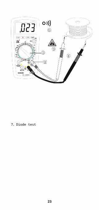
7、Diode test:①. Rotate " function / range switch "to position “ ”.②. Insert the black test lead into the “COM” socket and
the red test lead into V socket.(The circuit measured is "+ " pole), Connect test lead to both ends of diode to be checked ,the instrument indicates forward voltage drop of diode,units is volt:when the diode is reverse connected,the instrument indicates exceeding the range.
Caution:a. When test leads inconnect with resistance, instrument is
in the ultral range state(only reveal high position " 1 ").b. The electric current passed through the instrument
examined is about 1mA.c. Max input protection is 250V, higher than 250V may
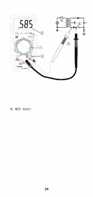
damage the instrument.8、Non Contact Voltage test:
11

. Function/range switch can carry though in any① position.
.NCV test no need to use test lead.②
.③ Press NCV test key-press, the liquid crystal display of the instrument stops revealing, give out very brief “ tick ” sound. NCV indicator lamp glittering at the same time, which indicate instrument enter NCV measure state already.
. Long press NCV test key-press without loose,and④ approach object to be tested by the top part of the instrument.If the object to be tested is of 60V—1000V AC voltage,the instrument gives out indication sound and NCV indication light.
Caution:a. If loose,the NCV key-press will bounce
automatically,the instrument quit NCV measureing state.
b. The instrument keeps auto power off state after quit NCV measuring state.If carry on other measurement,twice press key-press of power supply on-off switch.
9、Capacitance measurement.① Rotate " function / range switch "to position “F” and choose the suitable range.
. ② Insert the black test lead into the “COM” socket and the red test lead into CAP socket. Connect the test lead in parallel to both ends of the capacitance examined.
Caution:a. Should discharge the capacitance filling with the
electricity, then carry on measurementb. Should avoid examining the voltage by mistake,
otherwise may damage the instrumentc. Units: 1pF=10-6μF; 1nF=10-3μF.10、Frequency measurment①、Rotate " function / range switch "to position "Hz"
12

②、Insert the black test lead into the “COM” socket and the red test lead into V socket.. Connect the test lead in parallel to both ends of signal source examined.
Caution:a. The extent of the frequency signal should be controlled
between hundreds of millivolts and dozens of volts;when the singal is strong,should use the exterior attenuator; in yawp environment, can use shield cable on weak signal measurement. The voltage is higher than 100V, though can obtain reading, may exceed the error.
b. max input protection is 250V, higher than 250V may damage the instrument.
11、Temperature measurementRotate " function / range switch "to position "℃",
insert the black plug of the electric thermocouple into COM socket of the instrument,red plug into V socket of the instrument; Thermocouple measure terminal is located at temperature measure terminal.read the temperature value on the instrument display screen, the reading is . ℃Caution:a. After inserting thermocouple into the temperature
survey socket,it reveals temperature examined automatically; If not or when open circuit in electric thermocouple, it reveals the ambient temperature.
b.Simple-fixed K-type thermocouple, measure temperature limit 250℃ (short time measure is 300℃ ).
c. Max input protection is 250V, higher than 250V may damage the instrument.
12、hFE test①、Rotate "function/range switch" to "hFE" position.②、hFE specification test do not need test lead.③、Confirm the hFE is PNP or NPN type first,then insert
E、 B、 C pins to the meter’s jack.④、The meter shows hFE approx value,test condition:base
polarity’s current is approx 10uA,Vce approx 2.8V.
13

13、Data hold functionPress data hold key,display screen reveal “H” symbol
when the measuring data is locked,which is convenient for reading,recording.Press the key again, the key is reposited and the “H” symbol disappears and the instrument return to measurement states.14、Back light function:
Press the back light key and the LCD display screen give off back light,making the measured data more clear.Several seconds later the back light disappears automaticly.
VI、Panel description
1 、 DC Voltage measurement
14
2 、 AC Voltage measurement
3 、 DC Current measurement
15
4 、 AC Current measurement
16
5 、 Resistance measurement
17

6 、 Circuitry continity test
18

7 、 Diode test
19

8 、 NCV test:
20

9 、 Capacitance measurement
21

10、 Frequency measurement
22
11 、 Temperature measurement
23
12、 hFE measurement
VII、Technical specifications
24

Accuracy: (reading+word count) guarantee: one yearEnvironment temperature: 23℃℃Relative humidity: < 75%
1.DC Voltage
range
Accuracy
resolution
Accuracy
resolution65
01
650
5
650
86503
200m
V
(
)
μV
(
)
μV
2V 1mVμ
V
20V 10mV 1mV
200V100m
V10mV
1000V (
)1V
(
)
100m
V
input impedance:10 M.overload protection: range of 200mV is 250V.other range is peak value 1000V for DC Voltage or AC voltage.
2.AC Voltage
range Accuracyresolutio
n Accuracyresolutio
n
25

650165
05
6
5
0
8
6503
200m
V
(
)
—— μV —— ——
2V (
)
—
—1mV
(
)
100μ
V
20V (
)
10mV 1mV
200V 100mV 10mV
750V (
)1V
(
)
100m
V
input impedance: 10M.Frequency range: 40Hz-400Hz.Overload protection: the range of 200mV is 250V, other range is peak value 1000V for DC Voltage or AC voltage.Reveal: Average (the average of the virtual value of sine).
3.DC Current
range Accuracy resolutio Accuracy resolu
26

n tion650165
05
6
5
0
8
6503
200μA
(
)
— 100nA — —
2mA (
)
1μA
(
)
100n
A
20mA 10μA 1μA
200m
A
(
)100μA
(
)
10μA
2A
(
)
— 1 mA — —
27

20A ( ) 10mA
(
)
1mA
Voltage drop measurement:full-scale voltage drop:200mVOverload protection: below range 2A/250V fuse(HD6501 only),0.2A/250V fuse(besides HD6501) 4. AC Current
range
Accuracy
resoluti
on
Accuracy
resolu
tion650165
05
6
5
0
8
6503
200μA(
)— 100nA — —
2mA (
)
1μA
(
)
100n
A
20mA 10μA 1μA
200m
A
(
)100μA
(
)
10μA
28

2A
(
)
— 1mA — —
20A (
)10mA
(
)
1mA
Overload protection: below range 2A/250V fuse(HD6501 only),0.2A/250V fuse(besides HD6501) Voltage drop measurement:full-scale voltage drop:200mVfrequency range: 40Hz-400HzReveal: Average (the average of the virtual value of sine).5、Resistance
range
Accuracyresoluti
on
Accuracy
resolution650
1
650
5
650
86503
200
( )
0.1 ( ) 0.012k 1
( )
0.120 k 10 1200 k 100 102M 1k 100
20M ( ) 10 k ( ) 1k200M — ( ) 100 k — —
measure voltage output: <1V( position 200M approx2.8V).Caution:in position 200M, test lead short circuit and reveal number 10(more or less) after point. Subtract the number on LCD before testing from reading, you get the final result.
29

input protection:max 250V.6.Capacitance
range
Accuracyresoluti
on
Accuracy
resolution6505 6508 6503
2nF( )
1pF( )
0.1pF200nF 100pF 10pF2μF 1nF 100pF
200μF ( ) 100nF ( ) 10nF
30

measure voltage output:approx 40mVMeasure voltage frequency:approx 400Hz7.Frequency
rangeAccuracy
resolutionAccuracy
resolution6508 6503
2kHz ( ) 1Hz —— ——200kHz ( ) 100 Hz ( ) 10 Hz
input sensitivity:position 2kHz is 250mV,position 200kHz is 1.2V.Input signal range:150mV-100V.input protection:max 250V.8、Temperature
rangeAccuracy
resolution6508
-40 ~400℃ ℃ ( ) 1℃400℃~1000℃ ( ) 1℃
Temperature sensor:K-type thermocouple nickel chrome—nickel aluminium(EU-2)Open circuit characteristic:display environmental temperature.input protection:max 250V9、Diode test and circuit continuity test
rang
e
instruction test condition
indicate forward voltage drop of diode
forward current is approx 1mAReverse circuit voltage is approx 2.8V
the buzzer will beep when conductance resistance approx<30
Open circuit voltage is approx 2.8V
input protection: Max 250V.10、hFE test
rang
e
instruction test condition
hFECan measure NPN orPNP typed hFE specifications,display range:0~2000~~
Ib approx 10μA,Vce approx 2.8V
31

VIII、Maintenance Your digital multimeter is an accurate electronic instrument, should pay attention to safeguarding and maintaining1. Don't connect voltage higher than 1000V DC voltage or
750V AC voltage. 2. Don’t operate it if the back-cover is not closed properly.3. When upper left side display symbol, it indicates low
power.You need replace the battery after unfix the test lead;open the back cover then replace with battery with the same specification.
4. When replace the fuse,unfix the test lead.Unscrew the back-cover bolt to open the back-cover.Replace with fuse with same specification and screw on the bolt to close the back-cover.
5. The specification of the fuse: 6501fuse:2A/250V, other model multimeters :200mA/250V.
6. Remove the battery and put it in a dry, ventilating and few dust place if the instrument is not used for a long time..
7. Do not change the internal circuit at will to avoid damage.
IX、Accessories Enclosure1. user’s manual2. one pair of test lead3. Simple-fixed K-type thermocouple(6508 only)
32