Embed Size (px)
Citation preview

1
Revised 1.3 - 14/02/02
This document is property of SAIMA SICUREZZA Spa. Any part even if partial is prohibited without written autorisation by the owner
SAIMA SICUREZZA S.p.A.Indicatore 60/G - 52100 AREZZO - ITALYTel. +39 0575 9291 Telefax +39 0575 987097Telex 574074 SAIMA IE-Mail: [email protected]://www.saimanews.com
USE HANDBOOK
ELE 2000

2
Revised 1.3 - 14/02/02
This document is property of SAIMA SICUREZZA Spa. Any part even if partial is prohibited without written autorisation by the owner
Model Working specifications Serial number
Saima Sicurezza S.p.A. Production Division - Indicatore, AREZZO.
Date ...........................
Responsible for the testing .............................................
No part of this handbook can be reproduced in any form, electronic or mechanic system, without
SAIMA SICUREZZA S.p.A. written authorization. Drawings and descriptions of this handbook
are subject to changes or modifications without previous notice.
CONFORMITY DECLARATION : Saima Sicurezza S.p.A. declares that the booth mod. ELE2000, identifiable by the data at the foot of the page, is in accordance with the following laws: UNI8612 - ECC 89/106 - ECC 89/336 - ECC 73/23 as far as they can be enforced.
Thank you for trusting in our company and buying our products. We would like to remind you that this
handbook is an integral part of our ANTI-ROBBERY BOOTH and for this reason it is necessary to
follow its instructions. If the system has not been set, please examine the chapter about "Systeminstallation".
This handbook contains important information about safety and some information about the maintenance for users.
Saima Sicurezza S.p.A. is a company belonging to the Saima Group born in 1977. Since 1997 thecompany has obtained the UNI EN ISO 9001 certification.

3
Revised 1.3 - 14/02/02
This document is property of SAIMA SICUREZZA Spa. Any part even if partial is prohibited without written autorisation by the owner
TABLE OF CONTENTS.
Introduction.- Warranty. page 4- Destination. page 4- Identification. page 4- General safety regulations. page 5- Safety devices. page 5- Maintenance. page 5
Functions and use.- Technical description. page 6- Serial control console. page 7- Digital console (optional). page 9- Entrance/Exit procedure. page 13
System installation.- Preliminary checks. page 15- Unpacking. page 16- Disturbances sources. page 17- Positioning the booth. page 18- Lateral frames application. page 19- Wiring. page 20- Testing. page 21- Deactivation and setting aside. page 21
Maintenance.- System handbook. page 22- Maintenance card. page 23- Equipment on request. page 24- Labels. page 25- Working anomalies. page 26
Graphic representations- Figure 1A Serial control console. page 28- Figure 1B Digital control console. page 29- Figures 2-3-4-5 Views of the booth - push-button panels. page 30- Figure 6 Technical specifications. page 31- Figures 7A-7B-8 Booth movements - stopping feet. page 32- Figure 9 Embedded installation. page 33- Figures 10-13 Lateral frames application - examples of installation. page 34- Figure 11 Wiring. page 35- Figure 12 Booth pre-starting. page 36

4
Revised 1.3 - 14/02/02
This document is property of SAIMA SICUREZZA Spa. Any part even if partial is prohibited without written autorisation by the owner
Warranty
The booth is warranted for a period of one year from the testing date.
We are at your disposal for any further information you may need.
Please, remember that the warranty is void if you do not follow the directions here stated.
Any manufacturer�s liability is void if the user makes changes without the manufacturer�s previous written
authorisation.
Saima Sicurezza S.p.A. reserves the right to do all the necessary changes to improve the booth.
Destination
The booth must be used as a safety door equipped with entrance control. Restrictions:
The booth must be only used for the purpose it has been expressly conceived, taking into account the
restrictions shown inside the handbook. Any other use must be considered inappropriate and wrong.
The manufacturer cannot be considered responsible for any damage caused by inappropriate, wrong or
irrational use of the booth.
Identification
INTRODUCTION
The metal plate, shown here, contains all the information about the identification and operating system. It is placed on the booth's roof close to the internal inspection door.
Together with a possible maintenance request,
it is necessary to give the serial number written on the plate.
SERIALNUMBER
YEAR
MODEL
WEIGHT (Kg)
VOLTAGE (V)
FREQUENCY (Hz)
POWER (Kw)
MAX FORCE (N)
This handbook contains the maintenance instructions in order to get the best results and to achieve the
highest efficiency levels from your booth. Please, read these recommendations carefully, before
using the booth. Information about repairs, adjustments and settings different from those wich have been set
up are descibed in the technical handbooks. You can request them at Saima Sicurezza Spa directly.
Keep this handbook in a safe place for further consultation

5
Revised 1.3 - 14/02/02
This document is property of SAIMA SICUREZZA Spa. Any part even if partial is prohibited without written autorisation by the owner
General safety regulations
Only special trained and authorised staff can carry out the maintenance service. The manu-facturer is not responsible for any tampering or modification of the system, which has notbeen previously authorised. The removal or tampering of safety devices involves the breakingof European regulations concerning safety.
We exhort you to use only original spare parts. Our machines are designed to accept original
spare parts only. Skilled staff must carry out their settings, respecting the instructions hereby.
Please, be sure that when the system operates, all safety conditions are respected. If you
notice any irregularities, please stop the system immediately and call SAIMA SICUREZZA
S.p.A. maintenance service.
Only skilled staff must service the electric system, even if it is of small entity.
- Manual release of the system in case of total energyabsence;
- Internal button of aid call;
- Inaccessible mechanic motion;
- Metal plates showing the correct procedures to befollowed;
- Sensitive devices to open in case it is interceptedduring the closing phase;
- Electronic couple governor to keep the noticeablethrust on the door;
Safety devices
- Electric isolation;
- Safety transformer;
- Peripheral devices working by SELV.
We remind all of our customers to follow the norms in force, first of all the system's grounding and safety devices.
Maintenance
This door has been made in compliance with the regulations in force and taking into account the EuropeanCommunity Laws.We exhort you to verify the system every six-months. Only qualified staff must inspectc the system.During the scheduled maintenance, it is necessary to carry out the procedures mentioned in the system'shandbook (see Maintenance - System's handbook).

6
Revised 1.3 - 14/02/02
This document is property of SAIMA SICUREZZA Spa. Any part even if partial is prohibited without written autorisation by the owner
Technical description
The anti-robbery booth is equipped with a special system that allows to detect the presence of metal
objects and/or people (anti-hostage function) inside the transit area. Upon request, the booth can be
supplied with Biometric systems that recognizes people. Information on dimension is shown in figure 6.
N.B. The object detection system concerns only the internal area. So, it is possible to anchor
the booth to lateral structures (extension jamb, frames, etc.) without compromising the system.
The anti-robbery monobloc is made of steel sheet, strengthened tubular bars of considerable thickness.
The varnishing is made with special materials, which makes the end item weather and shock-proof.
The transit area parts are made with special resistance materials, as well as the door's supports where
the bent bullet-proof glass houses.
The Metal Detector is placed inside the lateral walls of the booth's entrance door. The Metal Detector's
control board and logic management are placed in the upper part of the booth and it is easy to inspect
them.
A plastic cover repairs the upper part from the dust. The door's movement is electromechanical and it is
controlled by direct current motors. The motor's underfeeding guarantees a further accident prevention
protection, in addition to the protection given of the photo-cells protecting the doors.
The booth is also equipped with:
- an intercom unit allows conversation between the control console and the outside;
- voice synthesis with one or more messages (on request);
- push-button panels with signalling leds (colours: red, yellow, green), intercom call button, microphone,
door opening button;
- stop button and intercom emergency call placed inside the booth;
- roof lamp formed by flash lights, loudspeaker, intercom button (on request);
- mechanic key that turns the booth on and closes it at night.
FUNCTIONS AND USE
If the mechanical key is not used there is a possibility that the doors will be
unlocked and can be opened manually should the batteries run down.

7
Revised 1.3 - 14/02/02
This document is property of SAIMA SICUREZZA Spa. Any part even if partial is prohibited without written autorisation by the owner
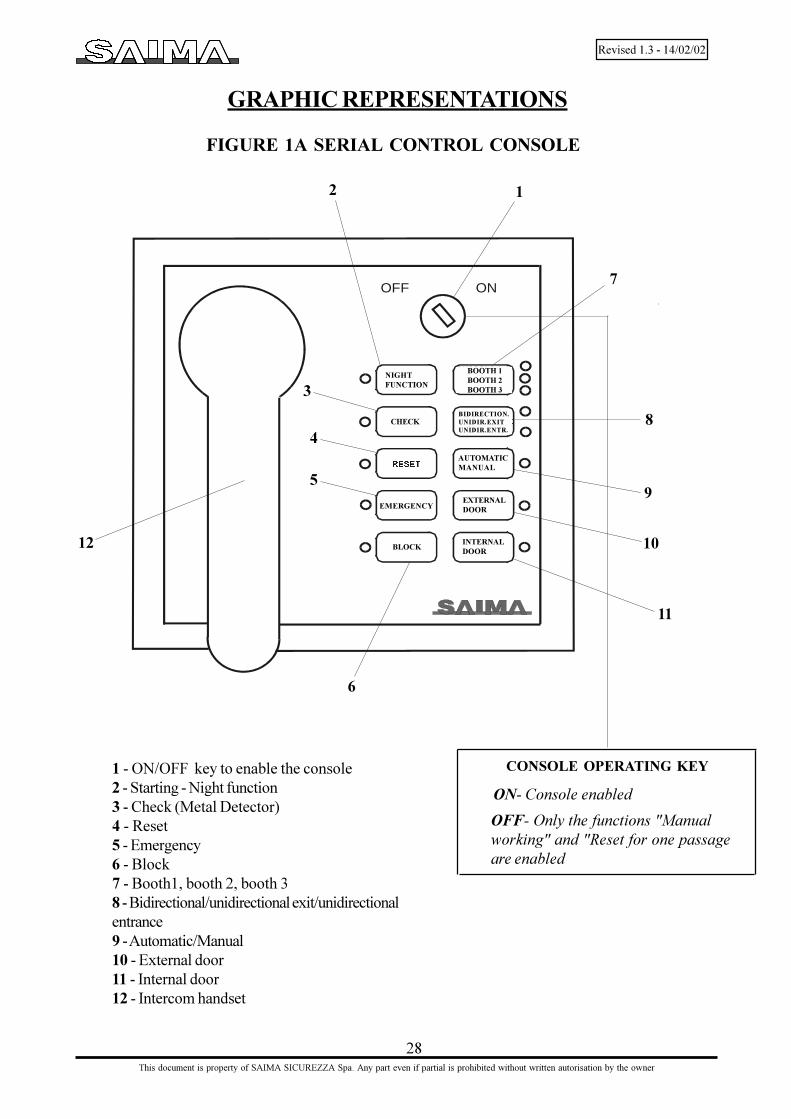
SEE FIGURE 1A SERIAL CONTROL CONSOLE
Serial control consoleThe serial control console is equipped with the main functions usually used to program the booth'soperating modalities.
The serial console can be used as single and secondary console combined with the digital console.
The functions can be enabled, disabled with a key: a signalling led will show the condition.
Serial console working
ON/OFF key to enable the console ON- Console enabled OFF-console disabled
Night FunctionBy pressing this button it is possible to enable the entrance to cleaning staff, maintenance staff, etc. withthe mechanic lock or with an impulse contact (lock with spring contact, electronic key, badge reader,etc.). Led on= function enabled Led off= standard function
CheckThis function checks the metal detector's permanent disconnection detector, weight and biometric checks. Led on= check enabled Led off= check disabled
ResetThis key allowes to cancel one of the alarms in progress, which are signelled by the special acousticsignal. Led on= reset for one passage Led off= standard working
Emergency It opens the two doors simultaneously. Led on= simultaneous opening of the doors Led off= standard working

8
Revised 1.3 - 14/02/02
This document is property of SAIMA SICUREZZA Spa. Any part even if partial is prohibited without written autorisation by the owner
Block It turns the booth off. It is not possible to enter or to exit. Led on= block of the doors Led off= standard working
Booth It controls up to three booths using the same console. By pressing this key, it is possible to select a booth and in case of alarm, it will move automatically.
Automatic/Manual By pressing this button, it is possible to control the manual and automatic phases signalled by the specialtwo-colour led. Green led= unidirectional entrance Yellow led= unidirectional exit Yellow/Green led = bidirectional
External door It allows to open the external door manually. Green led= external door open Red led= external door closed
Internal door It allows to open the internal door manually. Green led= internal door open Red led = internal door closed
Intercom
Should there be an intercom call from a booth, a bell in the console goes on. Lifting the intercom's handset, theconsole connects with the booth from where the call came from.When the handset is raised, and there are more booths on line, press the key 7 (booth1, booth2, booth3)to connect with the desired booth.
Resetting the main panel
For a complete Reset of the main panel press the buttons 8 and 11 togetheruntil all the console�s lights go off.Releasing the booth�s buttons it will automatically reset.
While Resetting do not do other operations on the console or the booth.
9
Revised 1.3 - 14/02/02
This document is property of SAIMA SICUREZZA Spa. Any part even if partial is prohibited without written autorisation by the owner
Digital control console with display
( optional)
SEE FIGURE 1B DIGITAL CONTROL CONSOLE
Main menu
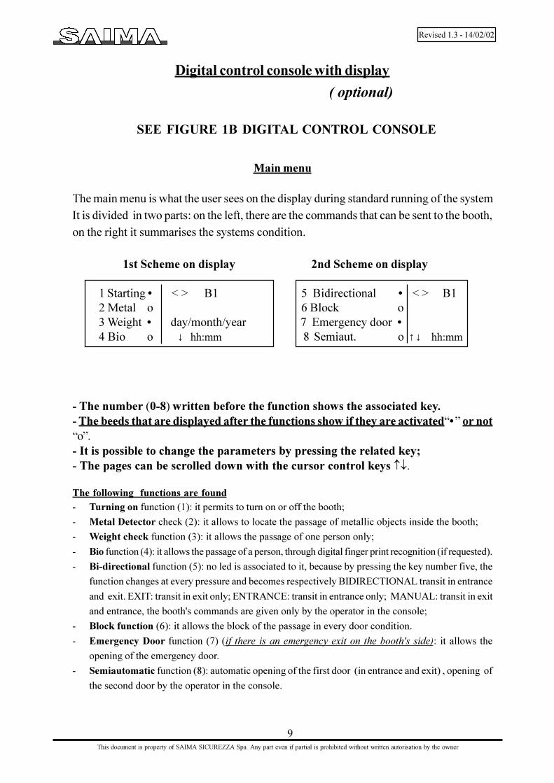
The main menu is what the user sees on the display during standard running of the systemIt is divided in two parts: on the left, there are the commands that can be sent to the booth,on the right it summarises the systems condition.
1st Scheme on display 2nd Scheme on display
1 Starting • < > B1 5 Bidirectional • < > B12 Metal o 6 Block o3 Weight • day/month/year 7 Emergency door •4 Bio o ↓ hh:mm 8 Semiaut. o ↑↓ hh:mm
- The number (0-8) written before the function shows the associated key.- The beeds that are displayed after the functions show if they are activated�•� or not�o�.- It is possible to change the parameters by pressing the related key;- The pages can be scrolled down with the cursor control keys ¯.
The following functions are found- Turning on function (1): it permits to turn on or off the booth;
- Metal Detector check (2): it allows to locate the passage of metallic objects inside the booth;
- Weight check function (3): it allows the passage of one person only;
- Bio function (4): it allows the passage of a person, through digital finger print recognition (if requested).
- Bi-directional function (5): no led is associated to it, because by pressing the key number five, the
function changes at every pressure and becomes respectively BIDIRECTIONAL transit in entrance
and exit. EXIT: transit in exit only; ENTRANCE: transit in entrance only; MANUAL: transit in exit
and entrance, the booth's commands are given only by the operator in the console;
- Block function (6): it allows the block of the passage in every door condition.
- Emergency Door function (7) (if there is an emergency exit on the booth's side): it allows the
opening of the emergency door.
- Semiautomatic function (8): automatic opening of the first door (in entrance and exit) , opening of
the second door by the operator in the console.

10
Revised 1.3 - 14/02/02
This document is property of SAIMA SICUREZZA Spa. Any part even if partial is prohibited without written autorisation by the owner
On the display's right part, there is the system's information which is subdivided as follows:First line:The symbol �<� and �>� refers to the door's conditions. If they appear as in the figure, the doors are closed. Ifthey are reversed, they show that the doors are open. Between the symbols �<�and �>� there is an emptyspace. When a person enters in the booth, this display space will show the stylised drawing of a person. Theletter "B" followed by a number shows the selected booth (in case of many booths).Second line: EmptyThird line: It shows the dateFourth line: It shows the cursor control keys of the menus and the time. Up arrow: previous scheme. Downarrow: following scheme.
KeyboardOn the keyboard there are both alphanumeric and symbolic keys. Some keys have pre-fixed functions; someothers have different functions on the basis of the context in which they are used (ref. fig. 1B)
• B key: commands and information on the display refer to the selected booth.
· �*� key on red background: it turns on the EMERGENCY function; to quit this condition, pressthe ENTER key. (Ref. Chapter �ALARMS�).
· key showing the "danger" symbol on yellow background: it releases the closed door; torestore it, it is necessary to press the ENTER key (Ref. Chapter �ALARMS�).
· �ESC�, �OK� and �F1� keys to execute the "SETUP" operation.
· F2 key puts on the "EMERGENCY FOR ALL BOOTHS" (it is enabled only if there are morebooths). To quit this condition, press the ENTER key.
· the �ENTER� key is used to end an alarm in progress.(Ref. Chapter "ALARMS�).
AlarmsOnce there is a booth alarm, the display shows what kind of alarm is in progress.During an alarm, by pressing the ESC key, it is possible to go back to the main menu without turningoff the alarm and the indication on the display. By pressing the ENTER key the booth's functions arerestored.• Release: shows that the booth's inside release button or from the console has been pressed.• Emergency: shows the �simultaneous opening of the two doors".• Metal Detector alarm: shows that a metal detector alarm is in progress. By pressing the ENTER key thisalarm allows the reset for one passage. Once this passage has occurred, the "Metal Detector check" goes onagain automatically.• Object in the booth: shows an object that has been deposited in the booth. By pressing the ENTER key thisalarm allows the reset for one passage. Once this passage has occurred, the "Object check" goes on againautomatically.• Exceeding weight: shows that the weight inside the booth is higher than the fixed threshold or that the anti-hostage device has detected more than one person inside the booth. By pressing the ENTER key this alarmallows the reset for one passage. Once this passage is ended, the "Weight check" goes on again automatically.•No net: shows that the system is working with batteries. This alarm does not allow the reset. By pressing
ESC, the right side of the display shows the writing: �No net�.
2
8
9
5
5
6

11
Revised 1.3 - 14/02/02
This document is property of SAIMA SICUREZZA Spa. Any part even if partial is prohibited without written autorisation by the owner
User MenuTo enter inside the user menu, press the F1 key.Enter the password (STD password = 999999), ESC to quit the menu.A list of functions will appear on the console display; these functions can be modifiedaccording to the necessities. With the arithmetic keys "+" and "-", it is possible to increaseor decrease the numerical values.With the ENTER key it is possible to enable or disable the functions with the symbols �·�- �o� and, when the symbol �↵� appears, it is possible to go in a sub menu.
Object weight Gr. 8000 (+ - ) This function is enabled with the specific weight card
Exceeding weight: Kg 120 only.
→ Buzzer • (+ - ) This function in enabled with the specific
Date � time ↵ weight card only
Summer time • ( ↵ ) (console keys bell)
Password change ↵ ( ↵ )
DATE/TIMETo change the parameters to the function Date/Time, it is necessary to select thefunction with the keys �� and �¯� and to press the ENTER key.
Time →11 � 54Date 5 � 1 � 99Tuesday True Solar TimeOK = save ↓ ESC
SUMMER TIMETo change summer time/true solar time (EU automatic updating)- select the parameter SUMMER TIME by with the keys¯;- press the ENTER key to disable the function (the symbol near the function will
change from l to ¡).
LANGUAGE SELECTION- Press F1- enter the numbers 999999 on the password - press Enter - select thedesired language scrolling down with the menu keys up to 7 - press Enter once chosen- Press ESC.
ENGLISH
OK = save ↓ ESC
Dis
play
Dis
play
OK = to save the parametersESC = to come back to the previous menu without savingthe parameters ↓ = to shift inside the menuNumeric keys= to set the desired value
Dis
play
OK = to save the parametersESC = to come back to the previous menu without savingthe parameters ↓ = to shift inside the menuNumeric keys = to set the desired parameter

12
Revised 1.3 - 14/02/02
This document is property of SAIMA SICUREZZA Spa. Any part even if partial is prohibited without written autorisation by the owner
Protection of the menuTo change the parameters in this function it is necessary to select it with the keys �� and
�¯� and to press the ENTER key. The display will show the following menu:
→ Starting o
Metal Detector check o
Weight check o
Bio check o
Autom. Manual o
Block o
Emergency door o
Semiautomatic o
Emergency o
External button o
Continuous rotation o
OK = save ↑ ↓ ESC
WARNING! The selected functions can be enabled or disabled even if the con-sole operating key is OFF.
The functions "External and Continuous rotation" are operative only for thebooths mod. ROTANT.
Password changeTo change the parameters in the "Password change" function, it is necessary to select it with the keys
�↑� and �↓� and to press the ENTER key.
Enter the new password and confirm it.
IntercomIn case there is a call from a booth, the bell in the console goes on. Lifting the handset, the consoleconnects via intercom with the booth from which the call came from.When the handset is raised, and if there is more than one booth on line, the right part of the display willshow the writing: "Intercom", and below: "B<number>�.By selecting the booth's key to communicatethe writing : �connected <number>� appears.
Dis
play
OK = to save the parametersESC = to go back to the previous menuwithout saving the parameters ¯ = to shift the cursor for theselection of the desired function insidethe menu

13
Revised 1.3 - 14/02/02
This document is property of SAIMA SICUREZZA Spa. Any part even if partial is prohibited without written autorisation by the owner
Turning on the boothThe booth can be turned on with the control console keys.Use the mechanic or electric keys for the first entrance and the mechanic key for the last exit (fig. 2).When the booth is turned on, the door's first opening cycle will be executed automatically; it has to beused for the entrance of the first person. For safety reasons, also the first passage is protected by themetal detector.
Standard transitAfter turning on the booth, make sure that the console is programmed for the standard transit; it mustoccur as follows:1) Press the call external button (detail n°6 fig. 2), which is placed beside the transit area and wait untilthe door opens.2) Enter in the booth.3) Wait for the external door to close and the internal one to open.4) Exit from the booth.
Metal Detector alarm (if there is).Every time somebody tries to transit through the booth with a metal object comparable in weight anddimensions to a weapon, the metal detector's allarm goes off. The alarm condition will activate a specialrecorded message contained in the voice synthesis that will invite the user to exit and deposit the metalobjects in a suitable box.The first door will stay open, so that the user entering can exit. In this way, it will close and checkautomatically the transit area, in order to verify the presence of metal objects left inside it.If the check will be negative, the monobloc resets automatically and it will be ready for a new transit.Otherwise, the external door will continue to open and close, until the object deposited inside will beremoved.
Transit with metal objects (if there is the Metal Detector).To allow the entrance in the protected area to a person with metal objects or weapons (for example,security guards, escorts for valuables) it is necessary to follow this procedure:1. If entering the user has set the metal detector's allarm off, the operator can turn off the metal
detector with the console, allowing the entrance;2. If the person, before entering, will ask entrance permission through the intercom, using the console
the operator can turn off the metal detector.In both cases, the operator has to only switch the metal detector in the ON position.
Door closed to the public.In order to prevent the entrance to the public, during fixed times, it is necessary to turn off the openingbutton of the external door using the �Bi-directional/unidirectional exit� command on the console. Inthis case, the user has to ask for the entrance through the intercom.
Entrance/Exit procedure
Anti-hostage alarm The weight check system is set up at 120 Kg of max. threshold by the head office directly (except for customer�s specific request). If there is a weight greater than the above-mentioned value, the exit procedure will be interrupted and the external door will remain open. In the meantime, a voice synthesis message will invite to contact the operator through the intercom. (If there is the digital console, the display will show the writing �ANTI-HOSTAGE ALARM� with thesimultaneous turning on of an acoustic sound).

14
Revised 1.3 - 14/02/02
This document is property of SAIMA SICUREZZA Spa. Any part even if partial is prohibited without written autorisation by the owner
Opening doors in emergency.The Emergency command on the console allows the simultaneous opening of the doors.If there is no power supply or if the booth breaks down, it is necessary to use the manual emergency.In this case, open the door from inside the bank (over the transit area), switch off the power supplyusing the ON/OFF switch placed on the electronic logic's rack.If there is a person inside the booth, and there is no power supply, it is possible to open the externaldoor manually.
N.B.: It is important to do this operation after having turned off the booth's main switch.
Automatic function in emergency.Should there be a power supply failure (220v) the batteries will start working automatically and willenable the functions for at least 30 more minutes. After such time the doors will not work. Bypushing the on switch on the main panel it is possible to use an extra energy reserve that will allowsome extra door openings.
Stop button inside the booth. (detail n°9 fig. 2).If the stop function is turned on when the doors are moving, it will allow only to open the doorsmanually.If the stop function is turned on when both doors are closed, the external door's brake releases, and themovements of the doors are blocked.To restore the booth's standard operation, it is necessary to reset it.
Passage authorization.Should undesired people be recognized or if there is the necessity to interrupt the entrance's passage,it can be done by switching to the OFF position the command on the console (fig. 1A - fig. 1B).To restore the normal passage switch to the ON position.
Booth does not function properly.Should there be problems with the booth's functions verify that the controls on the console are switchedto NORMAL TRANSIT before you do other checks. Unstable current or a long period withoutpower supply can cause problems to the booth, simulating for example, the presence of an object.To restore the booth to normal working condition, switch OFF the booth on the main console, wait afew seconds and then turn it on again.In case of a blackout or if the batteries have run out it is possible to open the doors as described in theemergency procedure.Should these malfunctions persist or should problems arise different from those described, please callour maintenance service:
TEL (+39) 0575 9291 - 987116 FAX (+39) 0575 929238
Procedure for the transit of two people. If two people have to transit simultaneously, (or, in any case, with the "Anti-hostage" alarm on) by pressing the Reset key (Enter key for the digital console) the system will end the entrance proce dure.
N.B.: The use of the main panel switch must be used only for emergencies since it can ruin the batteries and will need to be substituted if they do not re-charge.

15
Revised 1.3 - 14/02/02
This document is property of SAIMA SICUREZZA Spa. Any part even if partial is prohibited without written autorisation by the owner
Preliminary checks
SYSTEM INSTALLATION
Before installing the booth, it is necessary to check the following very carefully,in order to avoid possible failures.
N.B. Possible floor defects can cause an incorrect working of the system.
- Make sure that the booth can be carried in a vertical position to the desired place.
N.B.: When moving, avoid stresses on the Metal Detector's columns.
The booth cannot be reduced in dimensions, but it can be carried in an horizontal position for a short
way, then restore it to its vertical position.
N.B.: Moving the booth can cause mechanical damages. We suggest that only skilled and
equipped staff do the job.
Inform Saima Sicurezza when this operation is necessary.
- Verify that the ceiling of the location area is, at least, 280 cm high (every booth is 240 cm high). Thiswill guarantee the entry into the upper part of the system and to carry out the assembly and the
maintenance operations of the booth.
- Verify that disturbance sources do not cause metal detector failures (see the paragraph about
�Metal Detector disturbance sources� further on in this chapter).
N.B: For the Metal Detector to work correctly, it is important that the surrounding area re-mains the same and does not change in time.

16
Revised 1.3 - 14/02/02
This document is property of SAIMA SICUREZZA Spa. Any part even if partial is prohibited without written autorisation by the owner
Unpacking
After the unpacking operations, make sure that all the booth's components are complete. See if thereare any visibly damaged parts. In case of doubts, contact Saima Sicurezza S.p.A. directly.
PACKING PARTS (SUCH AS PLASTIC BAGS, FOAM POLYSTYRENE, NAILS, SCREWS,WOOD ETC.) MUST BE KEPT AWAY FROM CHILDREN�S REACH, AS THEY CAN BEEXTREMELY DANGEROUS.
Collect the above mentioned materials in special dumps.
Once the unpacking has ended, before assembling the booth, keep the components in a clean anddry place.Only skilled staff, which has been authorised by Saima Sicurezza S.p.A., can carry out the installa-tion and the assembly of the booth. The installation and assembly handbooks must be followed.
After assembling, the technician, and the customer, will test the booth and fill in the testing form. Thecustomer will sign the form if the test is positive.
A qualified technician must do the testing as well as all the adjustments and he must have the booth in running order.

17
Revised 1.3 - 14/02/02
This document is property of SAIMA SICUREZZA Spa. Any part even if partial is prohibited without written autorisation by the owner
M.D. disturbance sources
The metal detector is a device sensitive to electro-magnetic parasitic disturbances. In order to achieve thehighest performances, especially at the highest sensitivity levels, it is necessary to take some precautions whenyou use the structures in which it is placed.There are two different kinds of interference sources:1) mechanical disturbances2) electric disturbances.
Mechanic disturbancesThe metal detector has an electro-magnetic field generator that is able to induce an electromotive force in itsreceiving section. If the action of passing through metal objects modifies this force, the appliance will go on.The flux of magnetic field runs partly over the space surrounding the probe, too.Possible adjacent metal structures can introduce field absorptions, which can be due to:A- The moving of considerable metal masses or masses placed especially close to the aerials.B- Fixed metal structures that are placed near the Metal Detector can be replaced by panels made offormica, bakelite, polycarbonate or other insulating materials.C- Doors: if the doors are made with metal materials, they must be placed at a distance of at least 60 cm.The scroll formed by the door's metal section bars must be insulated. If the doors are made of insulatingmaterial (blindovis with wood, etc.) the mentioned precautions are not necessary.D- Electro-magnetic scrolls formed by structural components (metal frames, glass doors, metal ceiling strips,etc.) that because of movements or vibrations, do not have a stable nature. If the scrolls are liable to move-ment, they must be removed from the aerials or eliminated by insulation. If the scrolls are fixed, since they aremade of structures and section bars surrounding the metal detector, they must be insulated by an appropriatesplit. Otherwise, they can be made electrically stable by rivetings or electrical by-pass connections (in case ofvarnishing, remove the varnish coat on the faying surface of the screws, and use toothed washers).
Electric disturbancesElectric disturbances are produced when the aerials are near power supply cables (electro-magnetic fieldgenerated by alternating currents) or sources of impulsive electro-magnetic disturbances (electric motors witha high ignition absorption and related power supply cables, fluorescent lights, emergency generators, teleprinters,air conditioning units, remote control switches, etc.).
A- Power supply cables should be placed at a distance of at least 20 cm from the sensitive probe, especiallyfrom the receiving one (the distance depends on the currents intensity). They must also be twisted with a pitchgreater than 2.5 cm (if it is not possible, they must be inserted into a screening tube made of ferrous materialat least 2 mm thick).
B- Impulse sources must be removed, eliminated or screened.
b1. Fluorescent lights: the lights and their related reactors must be removed from the Metal Detector andespecially from the Metal Detector's receiving probe marked by the red stamp. Where it is possible,change the fluorescent lights with filament lights.
. b2. Electric locks: if they are placed close to the Metal Detector's probe, we suggest to use those suppliedwith screening; it is better to use motorized locks with a lower accelleration current.

18
Revised 1.3 - 14/02/02
This document is property of SAIMA SICUREZZA Spa. Any part even if partial is prohibited without written autorisation by the owner
Positioning the Booth
5) Should there be 2 or more booths coupled, determine the right and the left one. Specialinformation is shown on the booth's external side, under the package. It is important to respectthe position directions according to the installation environment.
The booth's installation can be carried out in two different ways:a) - Leaned installationb) - Embedded installation
LEANED INSTALLATION:1) Position the booth in the fixed place, putting the external side of it towards the outside of the place.
To move the booth, use a crane with a minimum lifting power of 1500 kg, using chains hooked tothe booth's four "A" upper edges, the crowbar on the bottom (fig. 7A) and the rollers under thebase (fig. 7B);
2) Free the booth from the external package only after positioning;
3) Secure the booth to the ground, so that it cannot move using the stopping feet ( 1-2-3-4) placedunder the rubber floor (fig.8). Stability is necessary for the booth to work properly.
4) Attach any possible fastenings to the booth's structure, paying attention to the screws, which cannotbe inserted for more than 2 cm. Do not make holes in the plastic and glassy parts of the structure.Do not make holes near the glass. Keep away from the edge of the lateral glass at least 3 cm; do notobstruct the inspection doors with plugging structures.
SEE FIGURES 7A-7B BOOTH MOVEMENTS
SEE FIGURE 8 STOPPING FEET

19
Revised 1.3 - 14/02/02
This document is property of SAIMA SICUREZZA Spa. Any part even if partial is prohibited without written autorisation by the owner
Lateral frames application
EMBEDDED INSTALLATION:The installation is embedded when the booth's floor and the external one are at the same level.If the building is new, it is necessary:- place the frame that Saima Sicurezza supplies upon request (fig. 9);- lay cement externally;- lay cement until the whole framework is covered.If the place exists already, it is necessary to make an opening in the floor with the frame's sameexternal dimensions that must be embedded and cemented.
1) Follow the directions previously described at point n°1 of the leaned installation
2) Embed the booth into the frame orienting it towards the right direction.
3) Use the plastic section bars (detail A, fig. 9) which are supplied upon request, as staff bedbetween the booth and the metal frame, adapting them to the installation and fixing them withsilicone.
SEE FIGURE 9 EMBEDDED INSTALLATION
SEE FIGURE 10 LATERAL FRAMES APPLICATION
To anchor the booth to the plugging structures, see the lower figure (fig.10).
Follow this procedure to apply the frames:1) Place the booth on the fixed place.2) With the plugging structures, stand against the chosen anchoring area on the booth (fig.10)3) At the same time drill the booth's frame and sheet, with an appropriate drill;4) Screw in self-tapping screws with of suitable size;5) Tighten the screws firmly.
Examples of installation.
SEE FIGURE 13 EXAMPLES OF INSTALLATION

20
Revised 1.3 - 14/02/02
This document is property of SAIMA SICUREZZA Spa. Any part even if partial is prohibited without written autorisation by the owner
1) Close to the booth's housing, make an electric connector box powered by a cable connected to thebank�s fuse box. The booth is supplied with a 1,5 m long power supply cable complete with plug.
We recommend you protect the power supply cable with a 15 A Id = 0.03 A differential switch. Make sure that the grounding is good.
N.B.1: We suggest you make the connector box with n°2 plugs and with the differential gear included.
Wiring
2) From the upper part of the booth, arrange a multipolar cable connecting the booth to the placewhere the operator is assigned to operate the console,using a duct with a diameter of 32 mm. Use
a duct different from the one used for the power supply cable.
3) In case of coupled booths, the connector box power supply must be separated. To connect with theconsole, all booths must be connected between them using Saima's connecting cable (code 5804530).
4) Connect the console's cable.
N.B.2: the cable's passage can be also made at the bottom (see fig. 2). In this case, arrange theinsertion of cables inside the booth's vertical passage holes when it is placed on the ground.
Use a duct separated from the one used for the power supply cable. In order to
respect the laws, it is necessary to ground the connection.
6) Start the booth with the ignition key placed on the console or with the key placed on the external sideof the booth. Wait approximately 10 seconds, during which do not touch the doors, so to avoid calibrationchanges.
7) Now the booth is ready to be tested (this must to be carried out by authorized staff only) and ready for use.
5) Switch on the bank's main, which feeds the booth with the privileged line. So, switch on the booth'smain.
WARNING! Before switching on the booth, remove the door's lock rod (detail C fig. 12) andloosen the "weighed basket" blocking nut (detail B fig. 12). This nut willbe lightly tightened by rotating it counterclockwise.
!!! N.B.: Do not move the nut "A" from the fixed position, since it has been set-updirectly by Saima Sicurezza during testing.
SEE FIGURE 11 WIRING
SEE FIGURE 12 BOOTH PRE-STARTING

21
Revised 1.3 - 14/02/02
This document is property of SAIMA SICUREZZA Spa. Any part even if partial is prohibited without written autorisation by the owner
REMEMBER THAT ONLY SKILLED AND AUTHORIZED STAFF CAN
DISASSEMBLE THE SYSTEM.
Testing
Once tested, verify:- Control that the console is working.- Metal detector alarm.- CE release button.- Photoelectric cells working.- Check door's movements.- Check the automatic reset.- Check the signal lights.For settings different from those pre-set, ask Saima Sicurezza S.p.A. for the technical handbooks.
Deactivation and setting aside
If the booth is not used for a long time, it is necessary to disconnect the power supply cable and thebatteries.We exhort the operator to put away the booth in a dry and sheltered place and to insulate every com-ponent from the floor and walls.

22
Revised 1.3 - 14/02/02
This document is property of SAIMA SICUREZZA Spa. Any part even if partial is prohibited without written autorisation by the owner
System handbookCheck the following every six months:
N.B. This handbook is an integral part of the system and it must be kept close to thebooth.
Weighing system Check the alignement of the internal floor /external floorCheck the charging cell
Check the response (person's object sample, zero setting) with tolerance
± 80 gr
Check the conditions of the silent blocks and leaf springs
Automatic power supply Check the batteries and their possible replacement
Check the working of the system without power supply net (only the internal
lamp of the booth must rest put off).
MAINTENANCE
TYPE OF CHECK CHECK DESCRIPTION
Electronic exchange Check there are no liquids filtered through
Check there are no over-heated parts Check the leds of the exchange
Control console Check the commutators
Check the buttons
Check the leds
Check and set, if necessary, the volume of the intercom.
Metal Detector Test with people's transit without metal objects and with metal
objects comparable to a gun mass.
Push-button panels and roof lamp Check the light signals
Check the opening buttons and the bell
Accident prevention Adjustment of the end-strok, open and closed doors
Emergency release tests
Check the maximum pair
Check the sensitivity of the accident prevention sensors
Motorization Check the cleaning condition of the slides and wheels
. Check that screws bolts of the wheels and belts are tightened
Check the clearances on the mobile parts in static condition
Check the motor and cinematic noise
Clearances on the mobile parts in Check the sliding surface and the wear conditions of the carriages
dynamic condition wheels
Check the conditions of the moving cables

23
Revised 1.3 - 14/02/02
This document is property of SAIMA SICUREZZA Spa. Any part even if partial is prohibited without written autorisation by the owner
Maintenance card
List of periodic checks carried out according to the procedures previously described.
N.B.: This handbook is an integral part of the system and it must be kept close to thebooth.
Date Technician Signature Next check Notes

24
Revised 1.3 - 14/02/02
This document is property of SAIMA SICUREZZA Spa. Any part even if partial is prohibited without written autorisation by the owner
Equipment on request
M.D. - Metal Detector equipped with small studs, with a rectangular or circular section inte-grated in the structure.
- Voice synthesis with more messages in many languages.- Internal micro-camera.- Badge reader.- Electric keys.- Electronic keys.- Remote opening radar.- Interface electronic card with emergency exit (push door).- Electronic card to manage the Self-service area.- Holding frame for the embedding floor.- Thermoform finishing frame for the embedding floor.
-

25
Revised 1.3 - 14/02/02
This document is property of SAIMA SICUREZZA Spa. Any part even if partial is prohibited without written autorisation by the owner
entrance
exit stick on the glass of the exit door
NOT
WALKABLE stick on the roof of the booth
stick on the doors' glasses make them visible
external side
to apply with the metal detector placed towards the opening button
Enter one at a time apply on the booth equipped with weight check
These labels must be applied on
the booth to give directions.
FOR THE SAFETY OF THE KIND CUSTOMERS,THE ACCESS DOORS ARE EQUIPPED WITH METALDETECTOR. SO IF THERE ARE METAL MASSES, THEY WILL BLOCK. PLEASE DEPOSIT ALL METALOBJECTS IN THE BOX.WE INFORM CUSTOMERS WITH PACEMAKERSTHAT THE METAL DETECTOR IS HARMLESS.
Labels
stick on the glass of the entrance door
remove when installing

26
Revised 1.3 - 14/02/02
This document is property of SAIMA SICUREZZA Spa. Any part even if partial is prohibited without written autorisation by the owner
The external door opens 1) Check and see if any dangerous or suspicius objectand closes constantly has been abandoned in the booth. Please do nota voice message asks to do anything and ring the alarm. If it is a different object"Please put all metal remove it as follows:objects in the box" 1.1) Do a "Reset" on the serial console and press "Enter" on the digital console. 1.2) Open the internal door using the exit button and remove the object.
1.3) After the door closes repeat the procedure described in point 1.1.
2) After having verified that the booth is empty follow the procedure described in point 1.1.
3) Should this problem arise immeditely after or after a short period of time please contact Saima's assistance service.
The door does not close. 1) Two people are in the booth at the same time: 1.1) Through the intercom ask one person to leave.
2) A person that weighs too much is inside the booth or an adult with a child: 2.1) Push "Enter" on the digital console and "Reset" on the serial console if you want to allow the person/people to pass. If not use the intercom and ask the person to leave.
3) The booth is empty: 3.1) Check the console's condition. See that the "block" function is not active on both the serial console and the digital console.
4) The booth is empty and none of the above conditions apply. (1-2-3): 4.1) Push "Enter" on the digital console and "Reset" on the serial console.
5) The photocell on the side of the passage is covered: 5.1) Remove the object in front of the photocell. 5.2) Clean the photocell's glass. 5.3) Turn off the photocell. If it is the external photocell push 10 on the serial console or 11 for the internal door. Press 7 for a second at the same time. The booth is reset, but you must call Saima's assistance service.
6) Call Saima's service.
ANOMALY POSSIBLE SOLUTIONS
Operating anomalies

27
Revised 1.3 - 14/02/02
This document is property of SAIMA SICUREZZA Spa. Any part even if partial is prohibited without written autorisation by the owner
The door does not work 1) Verify the settings ont the console.properly. 2) Do a console "Reset" (only the serial console).
The metal detector's alarm 1) Make sure that there are no metal objects near thegoes off constantly. external door.
2) Make sure that there are no maintenance workers or equipment near the booth.
3) On the serial console press "Control" to de-activate the metal detector and call Saima assistance service .
4) On the digital console it is possible to lower the metal detector's sensitivity (call Saima assistance service).
ANOMALY POSSIBLE SOLUTIONS
28
Revised 1.3 - 14/02/02
This document is property of SAIMA SICUREZZA Spa. Any part even if partial is prohibited without written autorisation by the owner
CONSOLE OPERATING KEY
ON- Console enabled
OFF- Only the functions "Manualworking" and "Reset for one passageare enabled
1 - ON/OFF key to enable the console2 - Starting - Night function3 - Check (Metal Detector)4 - Reset5 - Emergency6 - Block7 - Booth1, booth 2, booth 38 - Bidirectional/unidirectional exit/unidirectionalentrance9 - Automatic/Manual10 - External door11 - Internal door12 - Intercom handset
12
3
6
7
8
9
10
11
5
FIGURE 1A SERIAL CONTROL CONSOLE
&21752//2
5(6(7
(0(5*(1=$
%/2&&2
$8720$7,&2
0$18$/(
%,',5(=,21$/(
021286&,7$
OFF ON
�3257$
,17(51$
12
4
GRAPHIC REPRESENTATIONS
NIGHTFUNCTION
CHECK
EMERGENCY
BLOCKINTERNALDOOR
EXTERNALDOOR
AUTOMATICMANUAL
BOOTH 1BOOTH 2BOOTH 3
BIDIRECTION.UNIDIR.EXITUNIDIR.ENTR.

29
Revised 1.3 - 14/02/02
This document is property of SAIMA SICUREZZA Spa. Any part even if partial is prohibited without written autorisation by the owner
FIGURE 1B DIGITAL CONTROL CONSOLE
1 - Display2 - Selecs booth B3 - External door's manual opening.4 - Multifunction key5 - Setup keys6 - Reset7 - Shifting of the function menu8 - Emergency9 - CE release10 -Internal door's manual opening.11- Intercom handset.
2
3
4
5
6
7
CONSOLE OPERATINGKEY
ON - Console enabledOFF - Works only manuallyand resets for one passage.
1
10
8
9
7
ON
11
Turning on
MetalWeightAuto

30
Revised 1.3 - 14/02/02
This document is property of SAIMA SICUREZZA Spa. Any part even if partial is prohibited without written autorisation by the owner
intercom function led
intercom button
red: manual
yellow: transit phase
green: openopening button
red: manual
yellow: transit phase
green: open
opening button
microphone Possible passage for cables
1 2 3 4
5
6
7
8
9
10
12
13
15
14
1) -mechanic lock2) -radar (optional)3) -electric key (optional)4) -loudspeaker5) -small light6) -external push-button panel7) -electric key (optional)8) -badge reader (optional)9) -stop button and intercom aid call10) -RX (left)-TX (right) photocells
FIGURE 4 VIEW OF THE INTERNAL SIDE
FIGURE 3 EXTERNAL PUSH
FIGURE 5 INTERNAL PUSH
12)- radar (optional)13)- internal push-button panel14)- RX(left)-TX(right) photocells15)- fastening screws (n°2 int+n°2 est)
FIGURE 2 VIEW OF THE EXTERNAL SIDE
BUTTON PANEL
BUTTON PANEL

31
Revised 1.3 - 14/02/02
This document is property of SAIMA SICUREZZA Spa. Any part even if partial is prohibited without written autorisation by the owner
External side
Standard version with on-line entrance and exit Upon request: - exit at 90° right - exit at 90° left
Electric system
Power supply voltage : 220± 10%V - 50HzMaximum absorbed power : 0,2 KWBatteries : n°2- 2Ah 12V airtight lead in series
Inputs and outputs : 20 + 16Lines : n°3 RS232 (+ n°1 RS232 Reserved)
n°2 RS 485Motors : n° 2 - 24 VDC - 100WManagement logic : planning by a multiprocessor unitAutonomy without net: 60 minutes with 200 passaggesAutonomy without net, with M.D. on: 25 minutes with 200 passagges
Structure
Frame: made of tubes of 30/10 mm press-bent steel sheetPlugging structures: flat and bent stratified glass
(8+10+8- PVB0.76x2)Varnishing: Polyurethane with epoxy base
thin embossed Performances
Reset type: AutomaticTransit speed: 6 passages per minuteWorking temperature: -10 °C / +55°C
Dimensions and weight
Dimensions: Height 2400 mmLength 1050 mmWidth 1050 mm
Transit dimensions: Height 2000 mmWidth 550 mm
Weight : 800 Kg
FIGURE 6 TECHNICAL SPECIFICATIONS
205
120

32
Revised 1.3 - 14/02/02
This document is property of SAIMA SICUREZZA Spa. Any part even if partial is prohibited without written autorisation by the owner
Fig.7A Fig.7B
FIGURES 7A-7B BOOTH MOVEMENTS
FIGURE 8 STOPPING FEET
1 2
3 4
Rollers

33
Revised 1.3 - 14/02/02
This document is property of SAIMA SICUREZZA Spa. Any part even if partial is prohibited without written autorisation by the owner
FIGURE 9 EMBEDDED INSTALLATION
Holes for the passage of cablesWe suggest to keep these holesin correspondence of the internalside
Esterno
A
A
1070 x 1070 mm
70
100
External

34
Revised 1.3 - 14/02/02
This document is property of SAIMA SICUREZZA Spa. Any part even if partial is prohibited without written autorisation by the owner
FIGURE 10 LATERAL FRAMES APPLICATION
FIGURE 13 EXAMPLES OF INSTALLATION
Area where thebooth can beanchored to theplugging structure

35
Revised 1.3 - 14/02/02
This document is property of SAIMA SICUREZZA Spa. Any part even if partial is prohibited without written autorisation by the owner
FIGURE 11 WIRING
GROUNDINGCONNECTIONSTRUCTURE
N.1 CAVO 3 x 2,5 mmDIFFERENZIALE 0,03A
220V + T
N.1
CA
VO
MU
LTIP
OL
I
CONSOLLEBUSSOLA
DIFFERENZIALE 0,03A + 3 PRESE
BOOTHCONSOLE
N.1
MU
LTIP
OL
AR
C
AB
LE
CABLE
entrance
DIFFERENTIAL GEAR 0,03A + N.3 OUTLETS

36
Revised 1.3 - 14/02/02
This document is property of SAIMA SICUREZZA Spa. Any part even if partial is prohibited without written autorisation by the owner
A - Nut to adjust the height of the weighed basketB - Check nut to block the weighed basketC - Door lock rod
FIGURE 12 BOOTH PRE-STARTING
A
B
C