Embed Size (px)
Citation preview
Congratulations on your purchase, this is another of the innovative RV Products from Ultra-Fab Products Inc. This product will increase the stability and comfort of your camping for years to come. RVing is meant to be enjoyable…we’re making it that way. With our stabilizer system installed on your 5th wheel or travel trailer you can expect advantages such as:
• Stops front-to-back & side-to-side movement • Once installed there is nothing to stow away • Great time saver • Easy to use
Should you have any questions or problems, please call us at: 1-800-860-7571 Eastern Time from 8:00am to 4:00pm Monday thru Friday. To enhance you camping experience we invite you to check out some of our other products on our web site: www.ultra-fab.com. Thank you, Craig Searer President Ultra-Fab Products Inc. Page 1

TABLE OF CONTENTS DESCRIPTION PAGE # Parts List 3 Tool List 4 Installation setup 5 5th Wheel Line drawing 6 5th Wheel Assembly 7 Stiffening Pad 8 Spacer Mount 9 Detail “A” 10 Detail “B” 11 Detail “H” 12 5th Wheel Instructions 13-14 Travel Trailer Line Drawing 15 Travel Trailer front Scissor Jacks 16 Detail “E” 17 Detail “F” 18 Detail “G” 19 Travel Trailer Installation Instruction 20-21 Rear Jack 22 Detail “D” 23 Rear Jack Install Instruction 24 Telescoping Jacks 25 Setup Instructions 26 Warranty 27 Page 2
12
3
1013
164
5
6
15
14
9
11
12
8
7
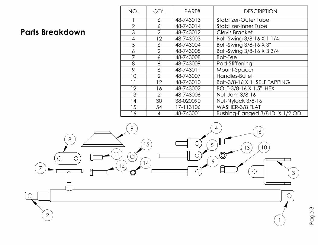
Parts Breakdown
Page 3
NO. QTY. PART# DESCRIPTION
1 6 48-743013 Stabilizer-Outer Tube2 6 48-743014 Stabilizer-Inner Tube3 2 48-743012 Clevis Bracket4 12 48-743003 Bolt-Swing 3/8-16 X 1 1/4"5 6 48-743004 Bolt-Swing 3/8-16 X 3"6 2 48-743005 Bolt-Swing 3/8-16 X 3 3/4"7 6 48-743008 Bolt-Tee8 6 48-743009 Pad-Stiffening9 6 48-743011 Mount-Spacer10 2 48-743007 Handles-Bullet11 12 48-743010 Bolt-3/8-16 X 1" SELF TAPPING12 16 48-743002 BOLT-3/8-16 X 1.5" HEX13 2 48-743006 Nut-Jam 3/8-1614 30 38-020090 Nut-Nylock 3/8-1615 54 17-113106 WASHER-3/8 FLAT16 4 48-743001 Bushing-Flanged 3/8 ID. X 1/2 OD.
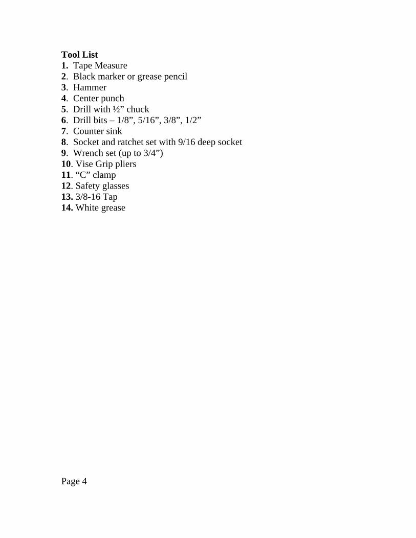
Tool List 1. Tape Measure 2. Black marker or grease pencil 3. Hammer 4. Center punch 5. Drill with ½” chuck 6. Drill bits – 1/8”, 5/16”, 3/8”, 1/2” 7. Counter sink 8. Socket and ratchet set with 9/16 deep socket 9. Wrench set (up to 3/4”) 10. Vise Grip pliers 11. “C” clamp 12. Safety glasses 13. 3/8-16 Tap 14. White grease Page 4
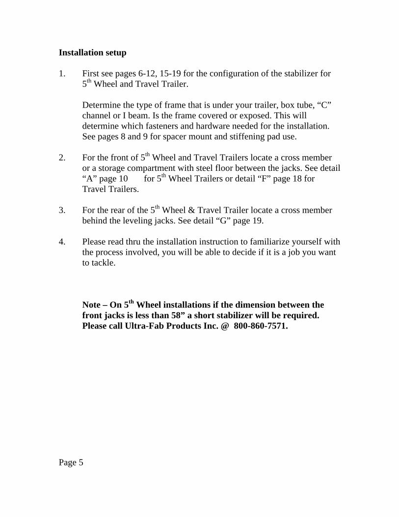
Installation setup 1. First see pages 6-12, 15-19 for the configuration of the stabilizer for
5th Wheel and Travel Trailer.
Determine the type of frame that is under your trailer, box tube, “C” channel or I beam. Is the frame covered or exposed. This will determine which fasteners and hardware needed for the installation.
See pages 8 and 9 for spacer mount and stiffening pad use. 2. For the front of 5th Wheel and Travel Trailers locate a cross member
or a storage compartment with steel floor between the jacks. See detail “A” page 10 for 5th Wheel Trailers or detail “F” page 18 for Travel Trailers.
3. For the rear of the 5th Wheel & Travel Trailer locate a cross member
behind the leveling jacks. See detail “G” page 19. 4. Please read thru the installation instruction to familiarize yourself with
the process involved, you will be able to decide if it is a job you want to tackle.
Note – On 5th Wheel installations if the dimension between the
front jacks is less than 58” a short stabilizer will be required. Please call Ultra-Fab Products Inc. @ 800-860-7571.
Page 5

5th Wheel Installation
Page 6
D
B
H
AG

but free to pivotAll Bolts need to be snug
Page 7
Towards outer edge
5th Wheel Assembly
Towards center
of 5th wheel
of 5th wheel
bushings. .500 Dia. (1/2")
to be drilled out for the
Towards Rear
These holes may need
Towards outer edgeof 5th wheel
48-743001Bushing
but free to pivot.
due to thinner gauge
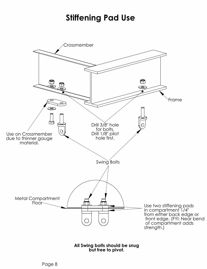
Stiffening Pad Use
material.
Use on Crossmember
All Swing bolts should be snug
Page 8
Use two stiffening padsin compartment 1/4"from either back edge or front edge. (FYI: Near bend of compartment addsstrength.)
Floor
Metal Compartment
Swing Bolts
Frame
hole first.
Drill 3/8" hole
for bolts.Drill 1/8" pilot
Crossmember
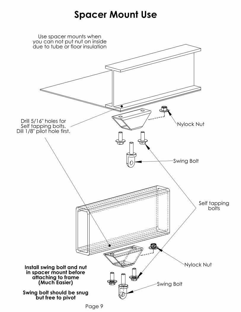
but free to pivotSwing bolt should be snug
(Much Easier)
Install swing bolt and nutin spacer mount beforeattaching to frame
Drill 5/16" holes forSelf tapping bolts.
Dill 1/8" pilot hole first.
Nylock Nut
Swing Bolt
Page 9
Swing Bolt
Nylock Nut
bolts
Spacer Mount Use
due to tube or floor insulationyou can not put nut on insideUse spacer mounts when
Self tapping
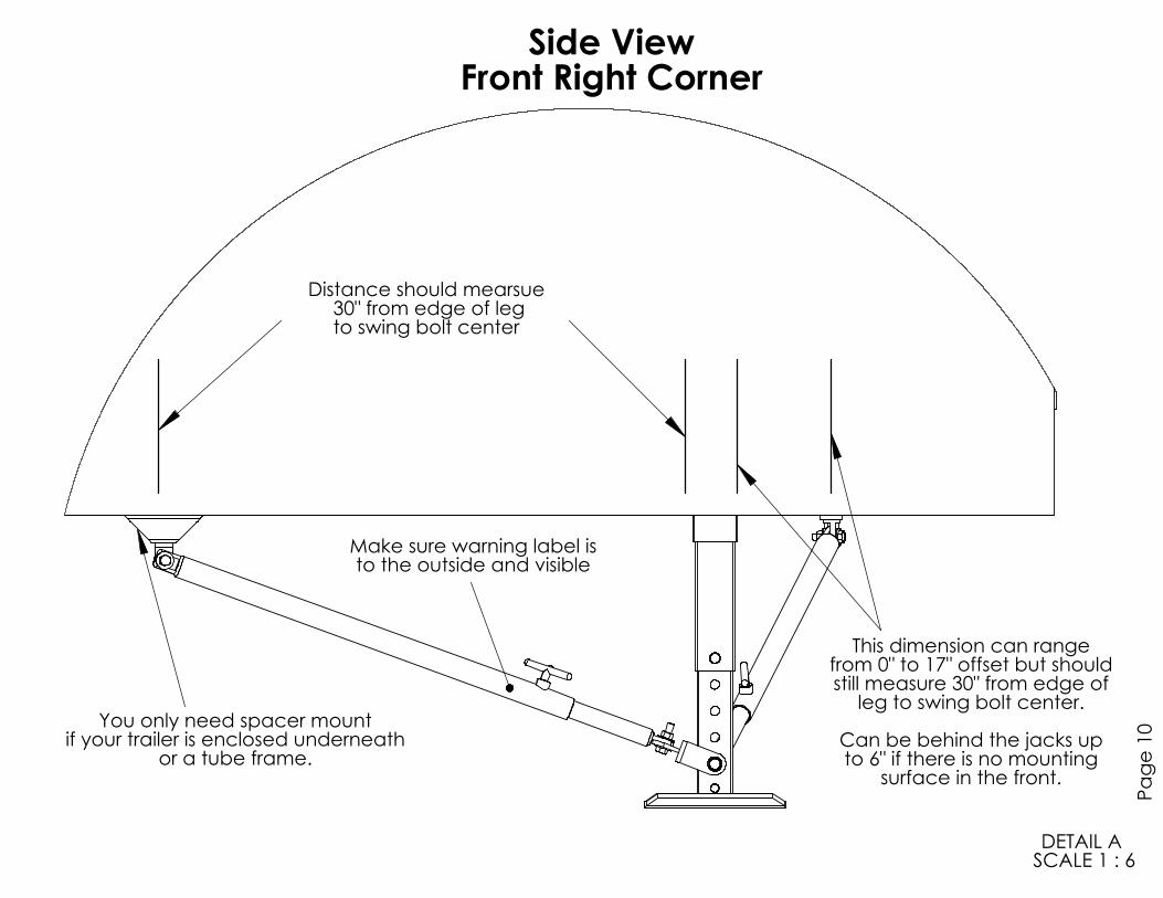
Front Right Corner
Make sure warning label is
SCALE 1 : 6
DETAIL A
to the outside and visible
to swing bolt center
30" from edge of legDistance should mearsue
if your trailer is enclosed underneath
or a tube frame.Can be behind the jacks up
surface in the front.
to 6" if there is no mounting
This dimension can rangefrom 0" to 17" offset but shouldstill measure 30" from edge of
leg to swing bolt center.You only need spacer mount
Side View
Page 10

Front Right Corner
Make sure warning label is
SCALE 1 : 5
DETAIL B
to the outside and visible
as many stiffening pads.
it is more than this you will need to seperate and use twiceThis setup works if dimesion between 5th wheel legs is 58" to 66" if
Front View
Page 11
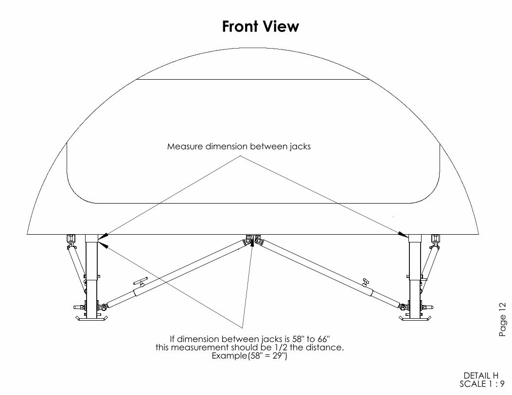
Front View
Example(58" = 29")
SCALE 1 : 9
Measure dimension between jacks
DETAIL H
If dimension between jacks is 58" to 66"this measurement should be 1/2 the distance.
Pa
ge 1
2
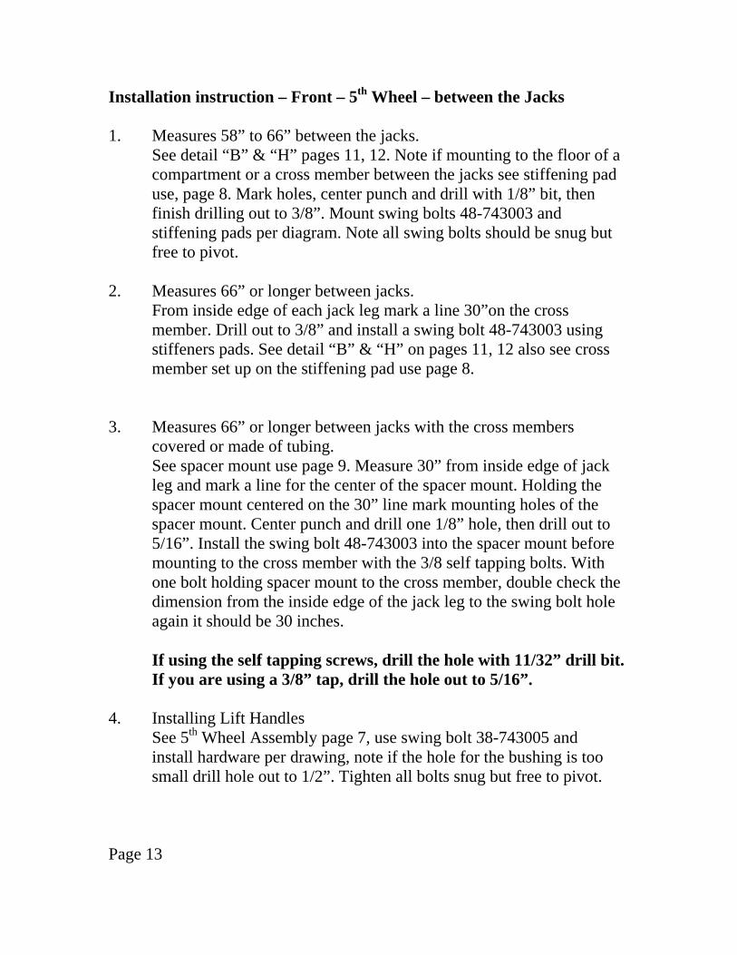
Installation instruction – Front – 5th Wheel – between the Jacks 1. Measures 58” to 66” between the jacks.
See detail “B” & “H” pages 11, 12. Note if mounting to the floor of a compartment or a cross member between the jacks see stiffening pad use, page 8. Mark holes, center punch and drill with 1/8” bit, then finish drilling out to 3/8”. Mount swing bolts 48-743003 and stiffening pads per diagram. Note all swing bolts should be snug but free to pivot.
2. Measures 66” or longer between jacks.
From inside edge of each jack leg mark a line 30”on the cross member. Drill out to 3/8” and install a swing bolt 48-743003 using stiffeners pads. See detail “B” & “H” on pages 11, 12 also see cross member set up on the stiffening pad use page 8.
3. Measures 66” or longer between jacks with the cross members covered or made of tubing.
See spacer mount use page 9. Measure 30” from inside edge of jack leg and mark a line for the center of the spacer mount. Holding the spacer mount centered on the 30” line mark mounting holes of the spacer mount. Center punch and drill one 1/8” hole, then drill out to 5/16”. Install the swing bolt 48-743003 into the spacer mount before mounting to the cross member with the 3/8 self tapping bolts. With one bolt holding spacer mount to the cross member, double check the dimension from the inside edge of the jack leg to the swing bolt hole again it should be 30 inches.
If using the self tapping screws, drill the hole with 11/32” drill bit.
If you are using a 3/8” tap, drill the hole out to 5/16”. 4. Installing Lift Handles See 5th Wheel Assembly page 7, use swing bolt 38-743005 and install hardware per drawing, note if the hole for the bushing is too
small drill hole out to 1/2”. Tighten all bolts snug but free to pivot. Page 13

Installation instruction – Front – 5th Wheel – sides 5. From the rear of the front jack leg measure back 30”, this will be the
dimension for the center of the swing bolt. See detail “A” page 10. (Note if your frame is covered or is made out of box tube you will use the spacer mounts) Then drill and install swing bolts 48-743003 into the frame.
When mounting swing bolts directly to the frame, use stiffener pads
when wall thickness is on the thin side. (approximately 1/8” or less) 6. INSTALLING THE STABILIZER TUBES Find the “T” bolt and put a dab of white grease on the threads and
start into the threaded boss of the outer tube. Insert the inner tube into the outer tube and mount to swing bolts
using the 3/8 x 1 ½ bolts. Note: the “T” handle goes towards the footpad and on top of the tube. See detail “A” page 10.
Apply warning label per detail “A”. Note: Tighten the bolts so that they are snug but free to pivot, if they
are too tight it will be hard to lift the inner tube of the 5th leg, if too loose the stability will be affected.
7. Install “Warning Label” It should be installed in a position so that it is visible to the operator of
the Electric 5th Wheel Jacks. (Next to the switch) If the Jacks are lowered without loosening the “T” bolts damage
may result. Page 14
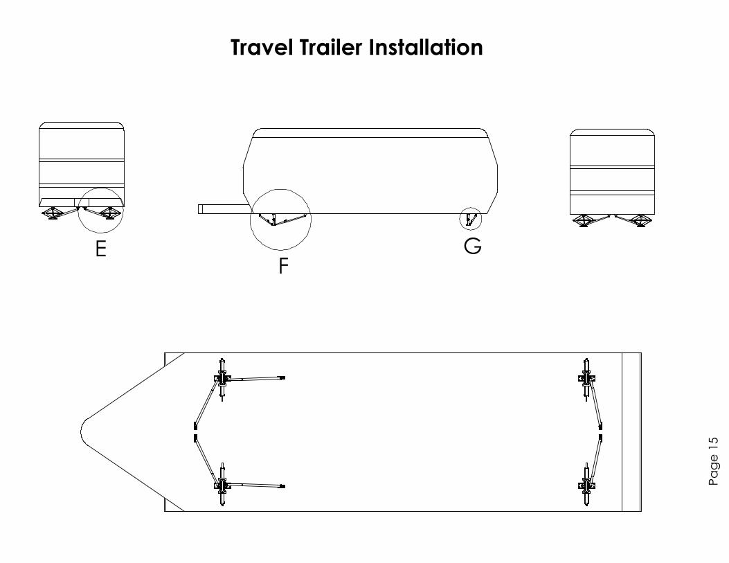
FG
Travel Trailer Installation
Page 15
E
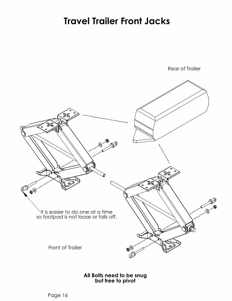
Travel Trailer Front Jacks
Rear of Trailer
All Bolts need to be snug
so footpad is not loose or falls off.
Front of Trailer
but free to pivot
It is easier to do one at a time
Page 16

Left Front Corner
Make sure warning label
SCALE 1 : 5DETAIL E
is to the outside and visible
Front View
Page 17
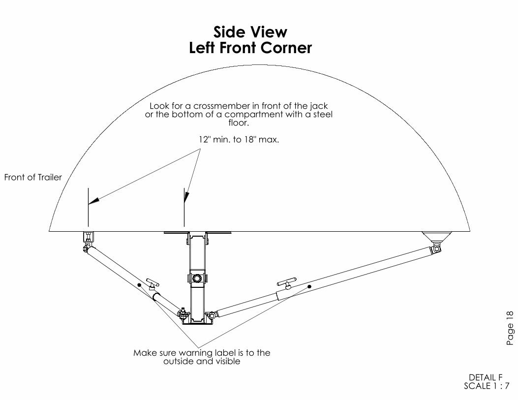
SCALE 1 : 7
DETAIL F
outside and visibleMake sure warning label is to the
Left Front Corner
Page 18
Side View
12" min. to 18" max.
Look for a crossmember in front of the jackor the bottom of a compartment with a steel
floor.
Front of Trailer
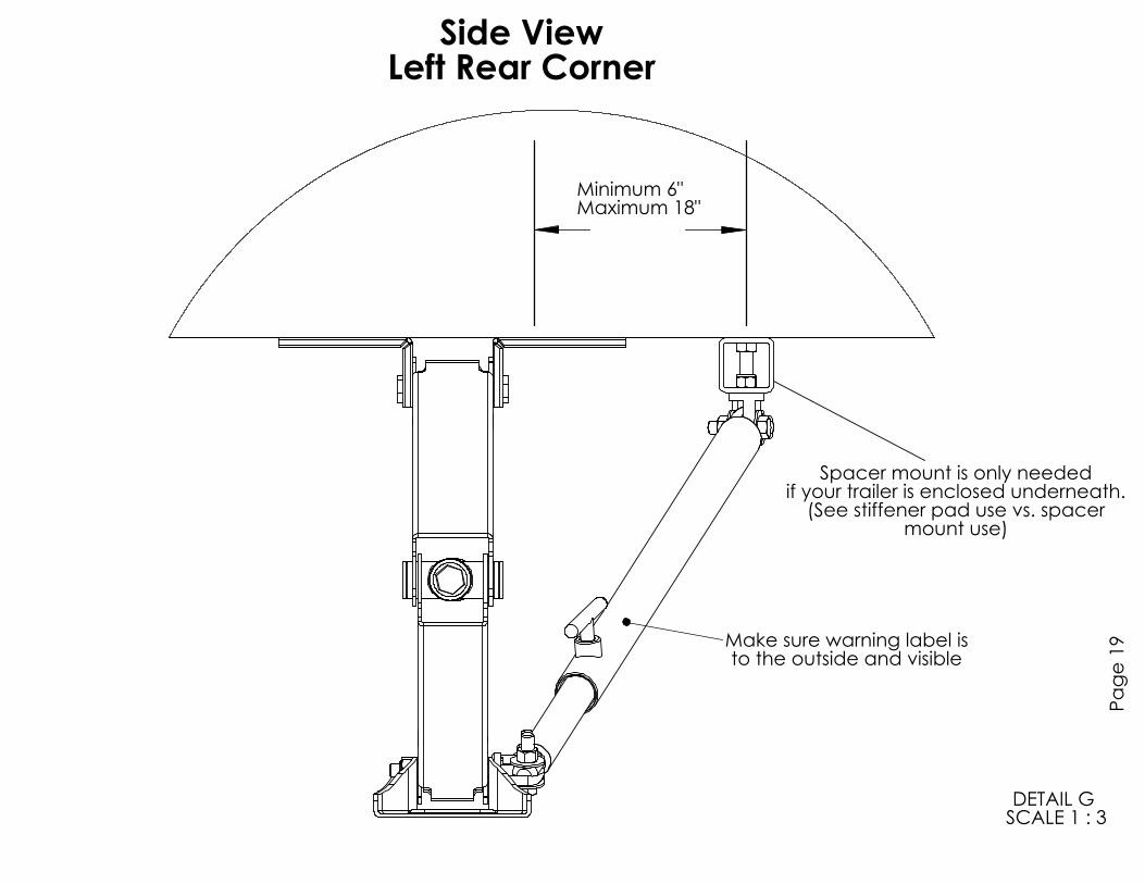
Spacer mount is only neededif your trailer is enclosed underneath.
(See stiffener pad use vs. spacermount use)
Minimum 6"Maximum 18"
SCALE 1 : 3DETAIL G
to the outside and visible
Make sure warning label is
Side View
Left Rear Corner
Page 19

Installation Instruction – Travel Trailer – Front – Swing Bolts 1. Start at either side front scissor jack, remove the lower inside pivot
bolt. ( note remove only one pivot bolt at a time ) Install a 3” swing bolt 48-743004 with pivot shoulder towards the rear of the Trailer. See Details “E” & “F” pages 17, 18.
2. Fasten with flat washer and locknut. Tighten snug, but free to pivot. See Detail “F” for the proper angle of pivot shoulder. 3. Remove the outside pivot bolt and replace with a swing bolt
48-743004 with the pivot shoulder towards the front of the Trailer. See Detail “E” page 17.
4. Installing the Stabilizer Tubes Find a “T” bolt and put a dab of white grease on the threads and start
into the threaded boss of the outer tube. Insert the inner tube into the outer tube, insert all the way into the
outer tube then pull out 1 inch and snug the “T” bolts. 5. If you used the Spacer Mounts (See Installation setup page 5) install the swing bolt 48-743003 and tighten, it will be easier to do so
before attaching to the frame. See Spacer Mount use page 9. Fasten the swing bolt (attached to the spacer mount if needed) to the end of the outer tube with the 3/8 x 1 ½ bolt. Refer to Stiffening Pad use page 8.
6. Front of the front Scissor Jack
With the Scissor Jack fully retracted, attach the inner tube end to the front swing bolt of the Scissor Jack. Swing the stabilizer towards the middle of the Trailer to line up with the cross member. Use the swing bolt 48-743003 as a guide, mark the cross member for the hole location. (If the Spacer Mount is being used mark two holes needed for each mount. note these are drilled to 5/16”, and tapped to 3/8-16) Drill and mount to trailer. See Detail “E” page 17.
Note: The “T” handles are on top of the outer tube as in Detail “E”, apply warning decals next to “T” handles. Page 20

7. Side of the front Scissor Jack. Detail “F” page 18. Attach Swing Bolt 48-743003 to the outer tube end of the stabilizer as described in step 5 above.
8. Attach the inner tube to the rear facing swivel bolt of the Scissor Jack.
(Make sure the stabilizer is adjusted properly. It should be fully collapsed and then pulled out 1” and tighten with the “T” handle.) Swing up to frame and mark locating hole or holes depending on hardware needed. (spacer mounts) If you have an “I” Beam Frame, the mounting location should be ¼ of the width of the frame in from the edge. Example: If the frame is 4 inches ¼ of this is 1”. See Page 9 When mounting swing bolts directly to the frame, use stiffener pads when wall thickness is thin. (approximately 1/8” or less)
Page 21
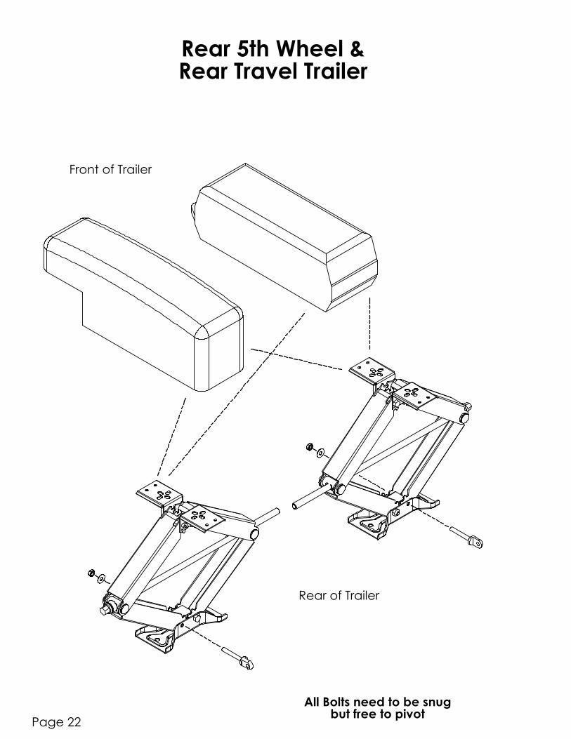
Rear of Trailer
but free to pivot
Front of Trailer
All Bolts need to be snug
Page 22
Rear 5th Wheel &Rear Travel Trailer
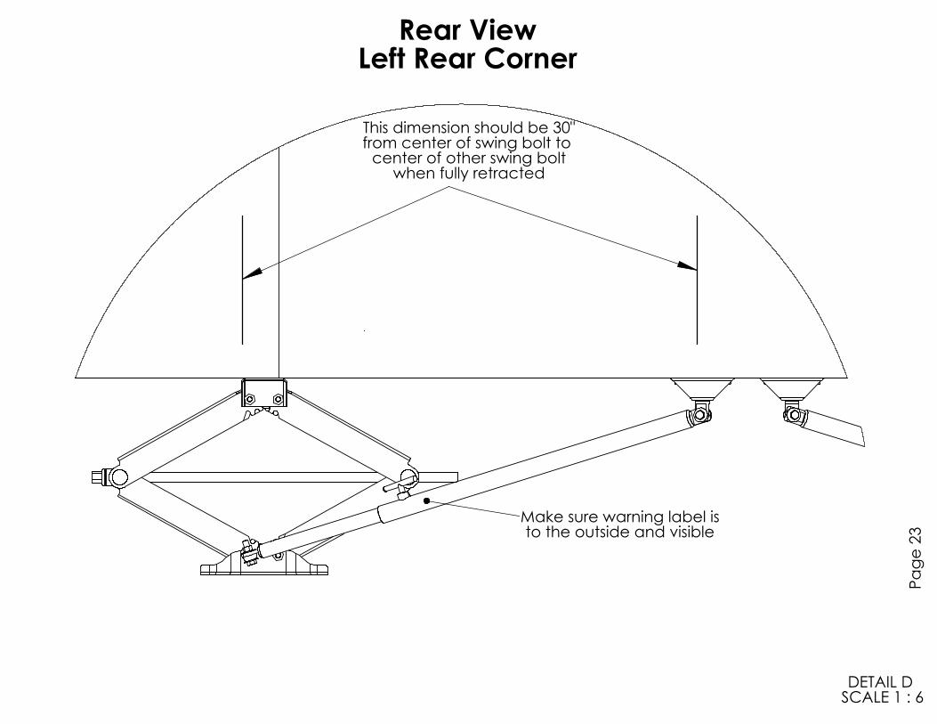
Left Rear Corner
Make sure warning label is
SCALE 1 : 6
DETAIL D
to the outside and visible
center of other swing boltwhen fully retracted
This dimension should be 30"from center of swing bolt to
Rear View
Pa
ge
23
Installation Instructions - Rear Stabilizer to Scissor Jacks 1. Remove the outside pivot bolt from the bottom of the Scissor Jack and
install a swing bolt 48-743004 with the shoulder towards the rear. Tighten snug but free to pivot. See Detail “G” & “D” pages 19, 23.
2. Install “T” bolts into outer tube as described for the front assemblies
and insert all the way then pull out 1” and snug the “T” bolt. 3. Attach the inner tube end of the stabilizer to the swing bolt previously
mounted at the bottom of the Scissor Jack. 4. If using the Spacer Mounts, attach the swing bolt 48-743003, then
attach to the outer tube. If not using the Spacer Mounts, attach the swing bolt to the outer tube of the Stabilizer. Swing the Stabilizer up to the cross member and mark the location for the mounting hole. Center punch and drill 1/8” hole then drill out to 5/16” and tap if using the Spacer Mounts or drill out to 3/8” for the swing bolt. See Stiffener Pad use page 8.
5. Tighten pivot bolts snug but free to move.
Page 24

Telescoping Jacks
Fasten this way if in front. If in back you need only 1 of the swing boltsto fasten arm.
Page 25
Setup Instructions 1. Before lowering any Jack with a Stabilizer attached loosen the “T”
bolt. Failure to do so may cause damage to your Jacks. 2. Unhook and Level your trailer as normal. 3. Tighten all the “T” bolts on all the Stabilizers.
Breaking Camp 1. Loosen all the “T” bolts before retracting any of the Jacks.
2. When all the Jacks are in the travel position snug up the “T” bolts so that they do not vibrate loose and fall out during the trip home.
Page 26