Embed Size (px)
Citation preview

.... . " F P, nPYREPORT OOCuME1A! ThON :AGE
-. , 7: ! .- :
--. . . .
AllUs 190 F inn II 14A V R. - , 1 ltr9I . TITLE AND SUBTITLE s. ,NOiNG NUMERS
New Non-Linear Optical Polymers 61102F 2303/A3
00 _ ____
Ni. AUTHC:;Cq I. Gorodisher (For G. E. Wnek and D. R. Uhlmann, P.I.'s)
PE- RFORMING ;RGANIZA' CN N',E -'4 A-_ 2 RFCO I NG - 4
Rensselaer Polytechnic Institute,/ |;EOOT 'i,','aRv
I University of Arizona AFOSR.-R 90 1(070
9. SPONSORING MONITORING AGENCY NAMESl AND AD 10. SPONSORING MON,17' NG
AFOSR/NC L 1 AGENCY REPORT k
Bolling AFB SI
Washington, D.C. 20332-6448 tv I 1990 1 F49620-88-C-0078
11.b SUPSTRIBUTION NOTEE
12a. DISTRIBUTION AVAILABILITY STATEMENT 12b. DISTRIBUTION CODE
Approved for Public Release:
:istribution is unlimited
13. ABSTACT Mjx,mum'200words)
New polyurethanes were prepared which exhibit non-linear optical activity. Thepolymers were poled during synthesis, advantage being takei of the fast polymeri-,zation kinetics. Second harmonic generation (SHG) was observed from thesepolymers. In selected cases, no decrease in the SHF signal (due to depolarization:)was observed at room temperature for up to one month.
The SHG activity of a series of organic model compounds was also investigated
I UBJECT TERMS 15. NUMBER OF PAGES
Non-Linear Optical Polymers; Polyurethanes, Seeond Harmonic 143Generation -. . 16. PRICE CODE
17. SECURITY CLASSIFICATION 18. SECURITY CLASSIFICATION 19. SECURITY CLASSIFICATION 20. LIMITATION OF ABSTRACT
OF REPORT OF THIS PAGE OF ABSTRACT
UNCALSSIFIED UNClASSIFIED UNCLASSIFIED SAR
14SN 75 40 .0 1.2 Sa , , : +0"-! - -1

L ? ~4 r 8
NOVEL POLYM1ERS AN',D ORGAN\,ICS FOR(
OPTIOAL SECOND!D hARMONIC GE-NERAT4ON
by Acceselon oFrNTIS QRA&I
ILYA GORODISHER DTIC TABUnannounced
Just ioation
S.M. Materials Science and Engineering .Massachusetts Institute of Technology Distribution/
(1986) Availability Codes
S.B. Materials Science and Engineering jkvall and/orMassachusetts Institute of Technology Dist Spel
(1985)I 4Submitted to the Department of Materials Science and Engineering in
Partial Fulfillment of the Requirements of the Degree ofDoctor of Philosophy in 'Polymers at theMassachussetts Institute of Technology
June 1990
© Massachussetts Institute of Technology
Signature of AuthorDepartment of Materials Science and Engineering
May 4,1990
Certified byMichael F. RubnerThesis Supervisor
Accepted by_Thomas W. Eagar
Chairman, Departmental Committee on Graduate Students
4 JPPo°ved,-0 . ~,
dl'tPibiAtjO '1 o lo ease :'ub' re

eP-T-AL-&ECONDHARMONIC GENERAT4ONby
ILYA GORODISHER
Submitted to the Department of Materials Science and Engineeringin Partial Fulfillment of the Requirements of the
Degree of Doctor of Philosophy in Polymers
ABSTRACTA series of bridged amino nitro diphenyl compounds
(below) was studied to determine the effect of the bridgingentity Z on the hyperpolarizability of the molecule.
02Na MNH-2Several series of novel polyesters and polyurethanes
were preparec by condensation of five alcohol monomers(below), containing second harmonic generation (SHG) activegroups, with diacid chlorides and diisocyanates.
N- (BCH) 2 N- (EtcH) 2 N- (B OH)2 a-i)2 N N(B GO) 2
#I J N2N N(11 *A) 2
o02 N02
IVFour novel diols and a novel tetrol were designed tocovalently incorporate nitroanilines and aminonitrodiphenylsulfides into the polymeric backbone.
Polymer structures were confirmed be NMR, IR and UVspectroscopies and elemental analysis. Polymers werecharacterized by X-ray scattering and DSC. Diols anddiisocyanates were corona poled during the course of thepolymerization. This approach showed improved active groupalignment vs the conventionally corona poled polymers asindicated by an up to 500% increase of the SHG.Polyurethanes showed excellent stability of the SHG signalat room and at elevated temperatures due to the hydrogenbonding "locking in" the SHG active dipole. Crosslinkedpolyurethanes showed no SHG signal relaxation after 1000second exposure to 120'C.Thesis Supervisor: Prof. M.F. Rubner
Associate Professor of Materials Science
0

TABLE OF CONTENTS
T itle pa g e ........................................................................................................... . . 1
Abstract ................................................. 2Table of Contents ........................................... 3L ist of F ig u re s .................................................................................................. . . 6List of T a b le s .................................................................................................. . . 10A cknow ledgem ents ........................................................................................ 12
I. Introd uctio n ........................................................................................ . . 13
1.1 VLSI Technology and Its Limitations ...................... 131.2 NLO Systems for SHG ................................................... 151.3 Polymeric SHG Systems ................................................ 16
II. S H G T heo ry ........................................................................................... 18
2.1 Material Requirements for SHG ................................. 182.2 Lorenz Model ...................................... 192.3 SHG Measurement Techniques ....................... 21
2.3.1 Pockel's Effect .................................................. 212.3.2 DC Induced SHG ................................................ 212.3.3 Solvatochromism ............................................. 222.3.4 Maker Fringe Method ....................................... 22
Ill. Bridged Diphenyl Compounds .......................................................... 29
3.1 Type I Molecule .............................................................. 293.2 Investigation of the Polarization
Mechanism of Type I Molecule .................................. 303.2.1 UV Spectroscopy Study .................................. 303.2.2 Nucleophilicit, of the Amine Study ..... 333.2.3 Dipole Moment Study ...................................... 353.2.4 NMR Study .......................................................... 36
3.3 Synthesis of Some Type I Molecules ....................... 393.4 Investigation of Their Polarization ........................ 47
3.4.1 UV Spectroscopy Study .................................. 473.4.2 Solvatochromism ............................................. 48

IV. Alcohol Monomers ............................................................................... 50
4.1 Synthesis of Diols I - V ............................................. 504.2 Characterization and Discussion ............................... 52
V. Diallyl Compounds and Cyclopolymerization ......................... 55
VI. Polyesters ............................................................................................. 58
6.1 Synthesis .......................................................................... 596.2 Characterization and Discussion ............................... 606.3 SHG Evaluation ................................................................. 61
VII. Polymers with Increased Concentration ofSHG Active Groups per Repeat Unit ............................................. 62
7.1 Poly(ANDS) ....................................................................... 627.1.1 Monomer Synthesis .......................................... 627.1.2 Polymer Synthesis ........................................... 64
7.1.2.1 Lantz Method ....................................... 647.1.2.2 W olfe Method ...................................... 65
7.2 Poly(ANDS Vinylene) ..................................................... 667.3 Poly(DNDS) ......................................................................... 68
VIII. Polyurethanes ...................................................................................... 70
8.1 Synthesis ............................................................................. 708.2 Characterization .............................................................. 79
8.2.1 HUPEG ................................................................... 798.2.2 NMR ........................................................................ 808.2.3 Elemental Analysis ......................................... 858.2.4 UV and IR Spectroscopies .............................. 858.2.5 DSC ........................................................................ 878.2.6 W ide Angle X-Ray Scattering ...................... 88
8.3 Poling .................................................................................. 89
IX. Polyurethane SHG Evaluation and Discussion .......................... 94
9.1 Reference Materials ....................................................... 969.2 SHG Relaxation Studies ................................................. 96
9.2.1 At Room Temperature .................................... 979.2.2 At Elevated Temperatures ........................... 98

9.3 Poling Field Strength Effect ......................................... 1009.4 Film Thickness Dependence ........................................... 1029.5 Alignment vs Conventional Corona Poling .............. 1049.6 Polyesters vs polyurethanes for SHG ........................ 1059.7 Effect of the Second Nitro Group on SHG ................. 1059.8 Anilines vs Diphenyl Sulfides for SHG ..................... 1089.9 Effect of the SHG Active Group Density on SHG...112
IX. Conclusions and Directions for Future Research ..................... 116
A p pe nd ix .......................................................................................................... 1 17References............................................................................................................ 1

LIST OF FIGURES
FIGURE # DESCRIPTION PAGE#
FIGURE 1 X2 of various materials p. 2FIGURE 2 Non vs Centrosymmetric Crystallization p. 6FIGURE 3 Schematic of the Maker Fringe SHG p. 12
ExperimentFIGURE4 Typical Maker Fringe Result for a Poled p. 14
PolymerFIGURE 5 Type I Molecule p. 16FIGURE6 Possible Polarizations for a Type I Molecule p. 17FIGURE 7 Modena's Chromophore XI p. 18FIGURE 8 Typical NMR Spectrum of a Type I Molecule p. 23FIGURE 9 NMR Shifts for the Proton Ortho to Amine p. 28FIGURE 10 NMR of 2,2'dimethyl4amino,'nitro Appdx
diphenyl sulfideFIGURE 11 NMR of 2methyl4amino4'nitro Appdx
diphenyl sulfideFIGURE 12 NMR of 2'methyl4amino4'nitro diphenyl Appdx
sulfideFIGURE 13 NMR of 2amino7nitro dibenzothiophene AppdxFIGURE 14 NMR of 4-hydroxy-4'nitro diphenyl sulfide AppdxFIGURE 15 NMR of 4-chloro-4'nitro diphenyl sulfide AppdxFIGURE 16 Various Alcohols for Polymerization p. 37FIGURE 17 Reaction of 4-chloro-4'-nitrodiphenyl Sulfide p. 40FIGURE 18 NMR of I AppdxFIGURE 19 NMR of II AppdxFIGURE 20 NMR of III AppdxFIGURE 21 NMR of IV AppdxFIGURE 22 NMR of V AppdxFIGURE 23 Potential SHG Compounds for p. 42
CyclopolymerizationFIGURE 24 NMR of VI AppdxFIGURE 25 NMR of VII AppdxFIGURE 26 Ketene Side Reacticr, p. 45FIGURE 27 NMR of Diphenyl Malonate AppdxFIGURE 28 Intrinsic Viscosity of Sin and Melt Polyesters p. 47FIGURE 29 NMR of VIII AppdxFIGURE 30 NMR of IX AppdxFIGURE 31 NMR of Clean IX Appdx

FIGURE 32 NMR of X AppdxF:GURE 33 NMR of Xl AppdxFIGURE34 Synthetic Route to Diaminodithiophenoxide p. 52
saltsFIGURE 35 Synthetic Route to Poly(Phenylene Vinylene) p. 53FIGURE 36 NMR of dichlorinated B AppdxFIGURE 37 uSC of Poly(DNDS) AppdxFIGURE 38 SAX of Poly(DNDS) AppdxFIGURE 39 NMR of Poly(DNDS) AppdxFIGURE 40 PUl p. 57FIGURE 41 Corona Alignment Polymerization p. 58FIGURE 42 PU2 p. 59FIGURE 43 PU3 p. 59FIGURE 44 PU4 p. 60FIGURE 45 PU5 p. 60FIGURE 46 DU1 p. 61FIGURE 47 DU2 p. 61FIGURE 48 DU3 p. 62FIGURE 49 DU4 p. 62FIGURE 50 DU5 p. 63FIGURE 51 HU1 p. 63FIGURE 52 HU2 p. 63FIGURE 53 HU3 p. 64FIGURE 54 HU4 p. 64FIGURE 55 HU5 p. 65FIGURE 56 NMR of PUl AppdxFIGURE 57 NMR of PU2 AppdxFIGURE 58 NMR of PU3 AppdxFIGURE 59 NMR of PU4 AppdxFIGURE 60 NMR of HU1 AppdxFIGURE 61 NMR of HU2 AppdxFIGURE 62 NMR of HU3 AppdxFIGURE 63 NMR of HU4 AppdxFIGURE 64 NMR of DU1 AppdxFIGURE 65 NMR of DU2 AppdxFIGURE 66 NMR of DU3 AppdxFIGURE 67 NMR of DU4 AppdxFIGURE 68 IR of PUl AppdxFIGURE 69 IR of PU2 AppdxFIGURE 70 IR of PU3 AppdxFIGURE 71 IR of PU4 AppdxFIGURE 72 UV of PUl AppdxFIGURE 73 UV of PU2 Appdx

FIGURE 74 UV of PU3 AppdxFIGURE 75 UV of PU4 AppdxFIGURE 76 UV of PU5 AppdxFIGURE 77 DSC of PUl AppdxFIGURE 78 DSC of PU2 AppdxFIGURE 79 DSC of PU3 AppdxFIGURE 80 DSC of PU4 AppdxFIGURE 81 SAX of PUl AppdxFIGURE 82 SAX of PU2 AppdxFIGURE 83 SAX of PU3 AppdxFIGURE 84 SAX of PU4 AppdxFIGURE 85 Parallel Plates Poling AppdxFIGURE 86 Parallel Plates Alignment Polymerization w/ Appdx
PETFIGURE 87 Par. Plates Align. Polymerization, Wnek Appdx
MethodFIGURE 88 SHG from PU1C15 AppdxFIGURE 89 SHG from PU2C1 5 AppdxFIGURE 90 SHG from PU3C15 AppdxFIGURE 91 SHG from PU4C15 AppdxFIGURE 92 SHG from PU5C1 5 AppdxFIGURE 93 SHG from DU1C15 AppdxFIGURE 94 SHG from DU2C15 AppdxFIGURE 9R SHG from DU3C15 AppdxFIGURE 96 SHG from DU4C15 AppdxFIGURE 97 SHG from DU5C15 AppdxFIGURE 98 SHG from HU1 C15 AppdxFIGURE 99 SHG from HU2C15 AppdxFIGURE 100 SHG from HU3C15 AppdxFIGURE 101 SHG from HU4C15 AppdxFIGURE 102 SHG from HU5C15 AppdxFIGURE 103 SHG from Repoled PU1C15 AppdxFIGURE 104 SHG from Repoled PU4C15 AppdxFIGURE 105 SHG from PE1C15 AppdxFIGURE 106 PU SHG Signal Relaxations at 250C p. 84FIGURE 107 DU5 SHG Signal Relaxation at 120 0C p. 85FIGURE 108 PU SHG Signal Relaxations at 100C p. 86FIGURE 109 PU SHG Signal Relaxations at 500C p. 86FIGURE 110 PU4 SHG Signal Relaxations p. 86FIGURE 111 PU1 SHG Signal Relaxations p. 86FIGtIRE 11? Al! of th, PU SHG Signal Relaxations p. 87FIGUHE 113 ETiect o FuiC5 Film Thickness on Its SHG p.

FIGURE 114 Alignment and Polarization of theDinitroanilines Covalently Bonded to Stiff p. 94Polyurethane Chains
FIGURE 115 Alignment and Polarization of theDinitroanilines Covalently Bonded to Flexible p. 94Polyurethane Chains
FIGURE 116 PU4 Polarization, Unavailable for PU3 p. 98FIGURE 117 Effect of the SHG Active Group Density in the
Polymer Chain on SHG p. 99FIGURE 118 Synthetic Route to a NLO Diisocyanate p.102FIGURE 119 Synthetic Route to a NLO Diamine p.103FIGURE 120 SHG from Repoled DU1C15 Appdx

LIST OF TABLES
TABLE # DESCRIPTION PAGE#
TABLE 1 UV Spectroscopy for Type I Molecules, Z=Se p. 31TABLE 2 UV Spectroscopy for Type I Molecules p. 32TABLE 3 Activation Energies for NAS for Type I p. 33
MoleculesTABLE 4 Dipole Moments of "Half Molecules" p. 35TABLE 5 Dipole Moments of Type I Molecules p. 35TABLE 6 Shifts of NMR Quartets in Type I Molecules p. 37TABLE 7 Elemental Analysis Results for the Type I p. 40
MoleculesTABLE 8 NMR Peak Assignments for the Type I Molecules p. 41TABLE 9 Powder SHG Results for Type I Molecules p. 42TABLE 10 Av vs CHCI 3 for Type I Molecules p. 43TABLE 11 Diphenyl derivatives p. 46TABLE 12 NMR Assignments for Sulfur Bridged Compounds p. 47TABLE 13 UV Maxima of Type I Molecules, A=N02, Z=S p. 47TABLE 14 Solvatochromism of Type I Molecules, A=N0 2 , p. 48
Z--STABLE 15 Elemental Analysis of I-V Alcohols p. 53TABLE 16 NMR Peak Assignments for the I-V Alcohols p. 54TABLE 17 NMR Peak Assignments for the Diallyl p. 56
CompoundsTABLE 18 NMR Assignments for the p. 64
DichlorodinitrobenzenesTABLE 19 Elemental Analysis Fit For Poly(DNDS) p. 68TABLE 20 NMR Peak Assignments for Poly(DNDS) p. 69TABLE 21 NMR Assignments for the PU Series p. 72TABLE 22 NMR Assignments for the HU Series p. 83TABLE 23 NMR Assignments for the DU Series p. 84TABLE 24 Synopsis of the Elemental Analysis Results for p. 85
PU'sTABLE 25 Transmission of PU's at the Harmonic Frequency p. 86TABLE 26 Peak Assignments for PU IR Absorbtion p. 86TABLE 27 Diisucyanates Reactivities p. 92TABLE 28 Mechanical Properties of the HUPEG Series p. 80TABLE 29 Effect of Polyurethane Structure on Its SHG p. 95TABLE 30 Reference SHG Materials p. 96T,-LE 'k r- rehaxatien of PJ's rt Elevated p. 97
Temperatures

TABLE 32 Effect of the Poling Field Strength on SHG of p. 103PU's
TABLE 33 Alignment Polymerization vs Conventional p. 104Poling
TABLE 34 Polyesters vs Polyurethanes for SHG p. 105TABLE 35 Comparison of SHG from Mono and Dinitro p. 106
UrethanesTABLE 36 Comparison of SHG from Anilines and Sulfides p. 109
on U's

ACKNOWLEDGEMENTS
The list of people who have contributed to the birthing ofthis document is rather extensive. The love, patience and supportof my beautiful wife Susanna during the largely unfunded researchyears is saintly in light of the sacrifices she had to make. I owe a
great deal to my parents who took a tremendous risk when theyapplied to leave Soviet Union to provide a chance for highereducation to their children.
I am indebted to Dr. Donald Uhlmann without whose support,advice and guidance I would not be receiving this degree. I want to
thank Dr. Gary Wnek for making me a chemist for being availablefrom 3000 miles away to listen to my synthetic ideas.
I owe a major thanks to Dr. Ray Zanoni to who helped mebuild a laser facility in Materials Science. I can even understand
some "Opticaleze" now. Drs. Henry Hall and Sam Yalkowskireceive my gratitude for letting me use their labs, equipment andpick their brains.
A special thanks goes out to Drs. Paul "Doom" Calvert, MikeWeinberg, and Brian Zelinski for patiently listening to severalversions of this presentation. Finally, I want to thank themembers of my Thesis Committee: Drs. Rubner, Roylance andChiang for their participation in this unusual defence on such ashort notice.

INTRODUCTION
VLSI
Recent advances in technology have created a need for newtypes of materials. This has been the driving force for the socalled "materials revolution." Perhaps the biggest and the mostchallenging demand on materials had been placed by theinformation processing industry.
The computer industry's drive to store as much informationas possible in a minimal amount of space and to access it in ashort time brought forth a new class of materials and processes.New semi-conductive materials, ceramics and polymers weresynthesized to meet this challenge.
Very large scale integration, VLSI, requires sharp resolutionpolymer films for lithography. This type of a photoactive polymer,called a photoresist, needed to be patterned by ultra-violet lightand selectively removed on a micron width scale. Currently thereis a strong demand for further integration. Sub-micron lithographycalls for new polymers that can be patterned by an X-ray source. Ashorter wavelength exposure source is needed because thedesired circuits need resolution finer than that defined by thewavelength of ultra-violet light.
However, the ultimate limit of this technology is not thewavelength of the radiation source. The problem is in the factthat two transmitting wires can lay only so close to each otherbefore the noise level becomes intolerable. This fact turnedscientists to look for a new way of transmitting information.Optical information processing looks very promising as a possiblereplacement for the current technology.
It offers light speed information processing via a laserbeam, optimizing the computational speeds. Non-linear opticsprovides a tool to increase the resolution by reducing thewavelength of light to a third (third harmonic generation or THG)or a half (second harmonic generation or SHG) of the input beam.Another advantage of he NLO processes is that the memorystorage capacity of the material is inversely proportional to the
13

square of the the wavelength of the writing beam. Thus, SHGphenomena, halving the input wavelength, quadruples the storagecapacity.
NLO SYSTEMS
In recent years the interest in optically non-linear (NLO)materials has been growing rapidly. This is indicated by anincreasing number of symposia held on this subject everyyear.'. 2 .3 While earlier research centered on the evaluation ofsingle crystals of small organic mole, as 4 and some inorganiccrystals,5. 6 the utility of polymers in the molecular design of NLOsystems was quickly recognized. 7. 8 SHG utility of variousmaterial types can be seen in Figure 1.9,12
10-50 DSMS
0 InSb
10-6 - GaAs
MNA
•U IBSP/MC
10-7 m-NA o PPNA
* MAP
POM PSO(NPP)
10-8 AZO dye PSO(DR)
0 LiNbO3 a in PMMA
3 KDP N urea DANS in10"9 aquartz PMMA or LC PVDF
0 Inorganic Xtals a Organic Xtals a Guest-host Covalent polyrm rs
10 1 0
0 5
FIGURE 1: SHG COEFFICIENTS SCALE FOR SOME MATERIALS.

Some of the organic single crystals that exhibit largeoptical non-linearities are not useful because of their low opticaldamage thresholds. Typically, NLO effects take place at high laserpower, which many organics cannot withstand. Processing thesecrystals and obtaining defect free films for device application isvery difficult. It is tedious to align them precisely at the phasematching angle.
Inorganics are limited to a small subset of crystallographicclasses that have no center of symmetry. Typically, the opticalnon-linearities from the inorganic materials are comparable tothe organics, but some of the best NLO inorganics are opaque atthe harmonic frequencies. 9 Optical damage thresholds are also amajor problem. 9 Processing problems for NLO device applicationsare confounding.
Another class of NLO materials consists of Langmuir-Blodgett (LB) films. These are organic films carefully deposited onsubstrates one molecular layer at a time. LB films are designed tohave a polar NLO head and a fatty acid tail. Commonly, polarsubstrates attract the polar head of the molecule, while theunattached nonpolar tails dangle. These systems tend to show atheoretical NLO ceiling for a particular polar group because of thecarefully controlled geometry and monomolecular dimension.However, the frailty of the films limits their practicalapplications.
Polymers appear especially attractive as "the" materials foroptical devices. They are durable and easily processed. Withproper molecular engineering they can be tailored to specificoptical properties. Already, polymers are employed in the opticalcircuits controlling airplane wing surfaces, as graded index lensesand as optical waveguide coatings. But for optical informationprocessing, a special class of materials has yet to be developed.These substances have to act as optical switching devices, laserbeam modifiers, parity checkers, and other signal processingcontrollers.
Two approaches to NLO polymer systems have beenattempted. Earlier efforts centered on the guest/host approach,where small NLO organic molecules were imbedded in atransparent polymer matrix. These films would then be orientedand evaluated for non-linearities. 9 ,1 0 , 1 1 Quick NLO signalrelaxation and limited solid solubility plagued these systems.
The second approach involved covalent bonding of the NLOspecies to the polymer backbone.' 0 , 1 2 ,13 Larger active group
15
concentrations can be achieved without rapid signal relaxation.Dipole alignment longevity was a major influence in choosingamorphous polymers with covalently bonded pendant NLO groups asthe system to be examined in the present work.
In the first chapter, material NLO requirements arepresented, along with some NLO theory. Chapter 2 investigates therole of the "bridge" of 4-amino-4'-nitro diphenyl bridgedcompounds in their optical non-lineariarity. Chapter 3 outlinesmonomer preparation for NLO polyesters, described in Chapter 5,and NLO polyurethanes, detailed in Chapter 7. Chapters 4 and 6describe attempts to synthesize polymers with more denselypacked NLO groups. Chapter 8 discusses the obtained NLO results.Finally, future research directions and possible improvements areoutlined in Chapter 9.
CHAPTER 1
THEORY OF SHG
NLO REQUIREMENTS
Optical non-linearity arises due to the non-vanishing ycoefficients of non-linear terms in:
P = PO + X1E + x2 E 2+X 3E 3 + ...+
where P is macroscopic polarization and E is the external electric
field. 14 For a single molecule, 1 becomes: 15
P = AL = ge -ig = aE +E2 + yE 3 + ... + 2
Where p is the microscopic or molecular polarization, Ile and p.gare the excited and the ground dipole moment of a molecule, and (x,
and y are the molecular analogues of X's in Eqn 1.If X 2' or the quadratic hyperpolarizability, is non zero, then
second harmonic generation (SHG) can be observed from thematerial. Similarly, if X3 is non zero, then third harmonic
generation (THG) is observed. While all materials have non-vanishing THG, three strict criteria must be met for efficient SHG:
1) The molecule must be easily polarizable,2) Organic molecules must be conjugated.3) The molecules must be non-centrosymmetric.
The third criterion must be met because when polarmolecuies crysia'hize, t',e cppositely ciharged ends tend 10 lign.This cancels the net dipole moment of the symmetrical molecules.Non-centrosymmetric molecules have dipole moments that do notline up with the crystal axis. Therefore, there is a net dipolemoment that gives rise to quadratic hyperpolarizability. 16
A classic example of this point is a comparison of 2-methyl-4-nitroaniline (MNA) and 4-nitroaniline (PNA), (Figure 2).
17

DW2
0 N 2
22
D 2
Figure 2: Centrosymmetric vs NoncentrosymmetricCrystallization
In the former, the methyl group disrupts the symmetry of the PNAand the oppositely charged molecular ends do not destructivelyalign in the crystal as to cancel the net dipole moment. Thus, eventhough both molecules possess a comparably high /P (42x10 3 0 for
MNA, 35x10 3 0 for PNA),1 7 only MNA has a non-zero macroscopicpolarizability due to its noncentrosymmetric structure.
This departure from symmetry is responsible for frequencydoubling during an SHG event. Lorenz model 1 8 describes themotion of an electron in a potential well under an applied electricfield. The harmonic model for a centrosymmetric crystal
dr d.r 2 e+2Y d-r +Yo r = -e E 3
dt2 m
applies if the restoring force acting on the electron is linear andgiven by f = oo2 r, where,
r is the displacement of the electron from its equilibriumposition,
e is the electron's charge,m is the electron's mass,wo is the electron's natural frequency,-f i -L ... c fnc'or andE is the applied electric field.
18

If the electron restoring force is nonlinear and if it can beapproximated by the first two terms of an infinite series: f = Wo2r- ir2 , then Eqn.3 becomes:
d2r dr 2 2 e 4S+ 2),d- +Oo r-r =--
2 dt 0 mdt
The solution to 4 is
22r ~ e E (Cod 52 2 22 2m (Woo- woi) (woo- (2(oi)2)
Note that the electron oscillates at twice the frequency of theapplied field. The second order susceptibility (quadratichyperpolarizability) is given by
e3 NX2 =-
2
6
2 62 2 2 2m (coo -wi) (coo - (2eo))2
Note that there are resonances at co= o and coo= 2o . Thus, theproduced harmonic wave will have twice the frequency of theinput fundamental. The fundamental and the harmonic wave willinterfere constructively and destructively. The relative poweroutput at each frequency can be derived as a function of the phasemismatch. 1 8
It is possible to obtain an optimal crystal orientation formaximum power output of the harmonic frequency when thedS-tructive interference is minimized. SHG materials arebirefringent. This iact makes it possible to obtain a propagaiiorn
c;r in a crystal wher the t-- inger.c 4. he naturaldispersion.: i ihis pioct. is , ', ase matchin-. In cases ofpoor phase matching, the harmonic signal is so weak thqt it isundetectable.
19

The present work deals with the effect of various bridgingentities between an electron donor and an electron acceptor on themolecular polarizability. A series of model compounds has beendesigned and prepared. Later, this work was expanded to includeseveral types of polymers which were evaluated for SHG.
There are several techniques available for the measurementof the quadratic hyperpolarizability of materials. Among them arepowder SHG, 5 the Maker-fringe method, 6 DC induced SHG, 4
solvatochromism 20 and the Kerr effect.2 1 The powder SHG methodhas been used as an efficient way to screen potential SHGmaterials obtainable in a crystalline powder form. 1 5
In the case of powder SHG technique, the phase matching isnot necessary. The crystalline samples are ground to form apowder of uniform particle size. The individual particles areazsumed to be single crystals. A pulsed NdIYAG beam is split sothat one arm is directed onto the sample, and the second armilluminates the reference. The sample SHG signal is compared tothat of the reference material, which is usually urea.Unfortunately, this method cannot be used to evaluate amorphousmaterials.
The Pockel's effect can be used to measure X2 according to:21
= An/n 03 Eo 7
where, y is the Pockel's constant
An = nL - n1l , the directional birefringenceno is the refractive index of unoriented materialEo is the applied electric field
After the light passes the electro-optic cell, consisting of theexamined material under applied voltage, it is polarized. If theelectro-optic cell is placed between two polarizers, the outputbeam is in the form:
Poutpul = Pinput * sin2 (-TLyno 3 Eo/X,) 8
where L is the ieiig n ol ie u ,, el,. .. .
y2 = -yn° 4 /b : 9
nI

DC induced SHG has been used to measure the microscopichyperpolarizability, or P, of the centrosymmetric materials insolution. 2 2 Here, a DC electric field is applied to a solution,removing the natural center of inversion. 3 can be calculated fromthe induced polarization.
Solvatochromism has been applied to estimate 3 of thepotential SHG materials. 2 0 This technique measures the shift ofthe maximum of the UV-vis absorbtion peak of the molecule understudy. Such absorbtion shifts, Av, are observed when the sample isdissolved in a series of solvents with varying polarity:
Av Af/(pe-Ag) 2 10
where
Af (E-1)/(2E+l) - (n2-1)(2n 2 +1) 11
and where , and n are respectively the dielectric constant and therefractive index of the solvent, p.e and g.g are respectively theexcited and ground dipole moments and f is the area under theabsorbtion peak, related to the transition dipole moment by:
f = I4ge 12 1 2
Thus, 03, given by
13 = Il-ge12 (lge -lg)/((o02 - C,2 )(WO0 2 4W 2 ) 1 3
can be easily measured
Finally, the Maker fringe technique 6 measures the intensityof the harmonic beam as the noncentrosymmetric sample rotates.The SHG intensity varies with angle due to the varying beam path
. -- f thpharmonic and the fundamentai wave e c-,=,,,,. .
fringe method has been used to measure the SHG from singlecrystals as well as from polymeric films. It has been furtherapplied to the measurement of SHG irom We moiecu'Ar mcinoiayei
21

in Langmuir-Blodgett films and from the surface monolayers ofcentrosymmetric solutions. Because this was the technique usedfor the measurement of the SHG from the corona poled polymers,in the present work, a detailed description of this method isappropriate.
In a uniaxial material, the power of the harmonic beam, P2 ,,is given by:
3 2
l 2,t 4 2 2 2 sin '(E)1A 2 2
n,,- n2,
where,A is the area of the laser beamP. is the power of the fundamental beamn. and n2 , are the refractive indexes of the material at the
corresponding wavelengths8 is the angle of incidence of the beam
to(, and T2. are Frensel-like transmission factors 6
dxx are the vector components of x2p is the projection factor which depends on the form of the
nonlinear tensor dxx and the direction of P2 o comparedwith the plane of incidence
and
2
2 22 nL (n- n 2s in T£(0) = ( 1 5
. 2 2 15n,+n2- 2sin 0
where,L is the film thicknessk = 1.064 im, the wavelength of the Nd/YAG laser,
for a coherence length larger than the film thickness. Simplified,the harmonic power becomes:
1

5224
1024n L p t T2, 2 2 16P = 24e 2 2 -2) ,clP
AX .+n2- 2sin
When a quartz reference is used in this experiment, thebeam diameter and the transmission factors can be assumed to beconstant for the sample and the reference. Thus, in a comparisonof P 2 wquartz and P2wsample these factors drop out. Furthermore, forthe special symmetry case of a uniaxially poled film,
p = (cos2eo/3 + sin2 0,)sine 2, + cosO.sinOecose 2. 17
Therefore, d values can be obtained from the experiment if therefractive indeces are known for the sample at the harmonic andthe fundamental wavelength.
sample 2 2 ( 2 2 2p2mp. n -, n2 ., n.. + n 2,,,.- 2 s i n
-quartz 2 2/2/Lquarz 2 18P2w dquartzSin . a2 iT LsampleI c(o)
where Ic = X / 4 (n, - n2w) 19
A typical experimental Maker fringe set up, such as the oneused in the present work, is shown schematically in Figure 3.
23

FIGURE 3
SCHEMATIC OF THE MAKER FRINGE SHG EXPERIMENT
bearm mirrorFIWZ]1-IUE plit NYAG/Nd LASER polarizer
color filters z jc= ii
ample qurtz
Rotator
Rotator ITranslationcontroller stage
i sIBM XT
computer iris
color filters
dielectricGP I5 Bfilters
FPMT PMT
• Amp]ifler ,

The Nd/YAG laser is Q-switched and the pulse repetitionrate is controllable. The beam is passed through a series offilters, screening out any frequencies above and below thefundamental. The beam is subsequently polarized as it travelsthrough the Glen laser polarizer. Then, the fundamental is dividedby a beam splitter, where the first part of the beam is directed atthe sample, while the second part of the beam passes through thereference material.
Before hitting the sample, the beam goes through an iris anda lens. The lens is mounted on a translation stage for precisionfocusing. The sample is mounted on an Oriel rotation stage,capable of x-y adjustments. The rotation is managed by the Orielrotator controller, which in turn, is computer operated. After thebeam passes the sample, possibly generating a harmonic beam,both beams pass through the second iris. The fundamentalfrequency is then screened out by a color filter. Interferometricfilter, admitting only the green light with 530-540 nmwavelengths, is the final optical device prior to thephotomultiplier tube.
The photomultipier tube (Hammamatsu 1P28A) is powered by1000 volts D.C., provided by the Pacific Instruments 310 powersupply. The reference beam is similarly processed, except that thereference is rigidly mounted and not rotated. The photomultipliertubes proportionately convert the harmonic light from thereference and the sample to direct current. The currents are fedinto the corresponding Stanford Instruments amplifier channels,where they are converted into D.C. voltage. The signals from theamplifier are passed to the EG&G 4100 boxcar integrator.
The boxcar integrator is triggered by the photodetector thatpicks up the laser pulses from the back mirror. Each trigger setsup a gate in the boxcar integrator which is aligned so that theharmonic signals from the amplifier are properly positioned insidethe gate. This alignment is insured by monitoring the gate and thesignals on an oscilloscope.
The boxcar integrator sends the SHG information to acomputer, which is also controlling the rotation of the sample. Asoftware program plots the angle of incidence vs the magnitude ofSHG.
These plots are the typical output of a Maker fringeexperiment. The sin 20 angular dependence (equation 14) of theharmonic signal is seen in the plots. If the samples are

sufficiently thick (more than a coherence length), actual fringescan be observed. Since the polymeric films are thinner than thecoherence length of the light employed, the SHG plots do not showfringes. 6 A typical 0-plot can be seen on Figure 4.
~~. . . . . . . . . . i. . . .
e 0 90 180 270 0
poi nts 0 250 500 750 1000
LB1EAM HITTING THE SAMPLE AS IT ROTATESJ
FIGURE 4: A TYPICAL MAKER FRINGE RESULTFROM A THIN POLED POLYMER
The SHG signal is maximum near 650 and not 900 aspredicted by 14. This is due to the increasing reflection of thefundamental beam from the glass substrate as the angle ofincidence becomes more obtuse. During a typical sample scan,depicted in Figure 4, the sample starts perpendicular to thebeam, with the dipoles aligned parallel to the beam. The samplerotates 3600 during the run. At 0 = 900, the sample is parallel tothe beam and the dipoles are perpendicular to the beam. At 0
0A
180 , the back of the sample or the glass substrate isorthogonally facing the beam.
The reflection of the fundamental beam from the glassbubstrate at the high angles of incidence is also responsible forthe asymmetry of the periodic sinusoidal response. Thus, becauseof the reflection, the harmonic signal from the incidence anglesbetween 900 and 1800, is less than that from the 00 to 900range.
The SHG maximum is normalized by the sample thickness..,. e harmonic data are compared for various samples. Ideally,
d:33 components Of X2 should be compared. However, the d33calculations require knowledge of the indices of refraction at the

fundamental and harmonic frequencies. For path lengths largerthan the coherence length, this information can be obtaineddirectly from the Maker fringe plot. The coherence length is thedistance between the two adjacent extrema. Since the angle ofincidence, 0, and X areknown, the birefringence is readily obtained from Ic = X/4(nw-n2,),Equation 19.
Since the beam path length in the thin polymeric films usedfor SHG is typically less than the coherence length, the samplebirefringence between the fundamental and the harmonicfrequency must be experimentally obtained. 12,23 Unfortunately,such equipment was unavailable, and the thickness normalizeddata were used.
27

CHAPTER 2STUDY OF THE BRIDGED DIPHENYL COMPOUNDS
In the last thirty years there has been a significant numberof studies of the "bridged" diphenyl compounds that are cappedwith an electron accepting group A on one end, and with anelectron donating group D on the other (type I molecule, seeFigure 5).
A= 0 2N NH 2 = D
FIGURE 5 TYPE I MOLECULE
More recently, SHG data interpretation once again has called upona better understanding of the charge interactions in a type Imolecule. 24.25 Equation 13 describes the dependence of ,3 on thedipole moments of the molecule.
= Ipeg1 2 (go - g.g) / (0)02 - -02)(002 - 4(02) 1 3
It is clear that the magnitude of the polarizability, which isdependent on the charge separation in the first excited state ofthe molecule, is ultimately responsible for the opticalnonlinearity. So the length of the conjugated bridge separating thecharges in the excited state and the dipoles in the ground stateplays a vital role in SHG.
Figure 6 shows several polarizations possible for a Type Imolecule. These chromophores have varying conjugation lengths,depending on the role of the bridging Z entity. Numerous attemptshave been made to demonstrate the role of the "bridge," Z, in thelong range electronic interactions between A and D.
28

H2N 0 ~ SWN
S N0 2 POLARIZATION
0-
NH2 NO POLARIZATION2
~0-
S NO POLARIZATION
AIIED BY AMINE INDUCTION
FIGURE 6: POSSIBLE POLARIZATIONS FOR ATYPE I MOLECULE WHEN Z = S
Investigators have used ultraviolet spectroscopy,2 6 ,27,28,29dipole moment measurements, 30 ,3 1 acid-base reaction kinetics,3 2
and nuclear magnetic resonance33 to characterize the differentimpact of heteroatoms in the Z position. It is important here toseparate the studies examining the ground state interactions fromthose in the excited state of the molecule. The magnitude of 03depends on the difference between the two dipole moments as canbe seen from Eqn. 13.
In the 1950's, researchers looked at the ultraviolet spectraof these compounds in efforts to relate the role of the "bridge" tothe energetic ease of the excited state formation. This energy isquantized and given by:
A E1-,2 = hv = hc/)X 20
where h is Plank's constant, c is the speed of light and AE--,2gives the energy required for electronic transition from state 1 to
29

state 2.34 Clearly, from Eqn. 20, transitions that occur at higherwavelengths X, or lower frequencies v , require less energy AE.
Typically, n-4n* and nr-4* transitions of conjugated moleculesare studied in UV spectroscopy. Both are the transitions from theground state to the first excited state. Modena 2 8 studied the 4-amino-4'-nitro-diphenyl selenide UV absorption spectrum andcompared it to those of 3-amino-4'-nitro-diphenyl selenide and 4-amino-4'-nitro-phenyl benzyl selenides. He found that methylenelinkage next to a selenide shifts n -4 n* transition by increasingthe wavelength at which it occurs from 343 nm to 346-348 nm.Moving the amine from para to meta renders the excitation moredifficult by shifting the wavelength from 343 nm to 339 nm.
Modena also looked at the acceptor A in the 4' position in a cappedseries of 4-nitro-diphenyl selenides. The summary of the UVspectra is shown in Table 1.
TABLE 1UV spectroscopy data for
Se
0 0A NO 2
increasing e- donor ability
A H OH O~e NH2 NMe 2 O-
lax(rim) 337 338 343 341- 360-364
maxima for n -- 7* in nm
Modena's conclusion that "the excitation of the chromophore (XI)[Figure 7] is not significantly modified by the substituent A" isin direct opposition to his own data.
' S - -* . .. =\ = - e
-O
FIGURE 7: MODENA'S CHROMOPHORE Xl
30

The wavelength of transition increases/energy decreases withincreasing electron donating ability of A. According to March, 43this electron donating ability can be arranged as follows: -O >NMe2 > NH 2 > OCH 3 > OH > H
When Modena's data are put together with Szmant and McIntosh's,35 who examined the series of diphenyl compounds appearing inTable 2, a definite pattern emerges.
Table 2: UV spectroscopy for
D = NH2 H NH2
Z A =l NO2 NO 2 HSO 2 267nm 261-262nm 292nm
SO 276nm 265-267nm 276nm0 300nm 300-301 nm 243nm
S 343nm 338 nm 255nm
Se 343nm 337 nm 273*nmMaxima locations are listed in nm. *Here, D=N(Me) 2 . No data wereavailable for D=NH2. Since data for the Se bridge were in goodagreement for NH 2 and NMe 2 for various A's, the value of 273 nmwas used.
The Z entities, which have been categorized as electronacceptors, such as SO and SO 2 , the Series I molecules undergoexcitation the easiest (at the longest wavelength) when diphenylmolecules are solely capped by an electron donor such as an amine.When this donor is replaced by an acceptor (4-nitro-diphenyls) theexcitation becomes much more difficult energetically. If theacceptor bridge is placed between a donor and an acceptor, as inamino-nitro-diphenyls, then the nitro group hinders theinteractions between the bridge and the donor, increasing theexcitation energy.

When the bridge is a donor, such as oxygen, the exactopposite is observed. Amino-diphenyl-ether shows a maximum inthe UV absorbtion spectrum at 243 nm. Nitro-diphenyl etherundergoes n-t* at 300-1 nm. In the cases of sulfur and seleniumbridged molecules, the Z atoms interact with both donors andacceptors because the 4-amino-4'nitro diphenyl sulfides andselenides have maxima at 343 nm, while the diphenyl sulfides andselenides with only one para substituent absorb farther in theultraviolet.
Hence, UV spectra show that all bridges examined "feel" thepresence of both amine and nitro groups. But only in the cases ofsulfur and selenium is the n-* transition eased when bothelectron donor and acceptor are present simultaneously.
In the early 1960's, Litvinenko's group attempted to monitorthe role of the bridging Z entity by examining the nucleophilicityof the amine in the series of 4-amino-4'nitro diphenyl compoundsand in the 4-amino-diphenyl series.3 2 To this end, they monitoredthe kinetics of the reaction of these amines with picryl chlorideand with nitrobenzoyl chloride. Activation energies and speeds ofthe reactions were measured and are listed in Table 3 for aseries of ethers, sulfides, selenides, amines, methanes, ethanes,vinyls, acetylenes and biphenyls.
TABLE 3ACTIVATION ENERGIES FOR NUCLEOPHILICAROMATIC SUBSTITUTION REACTIONS OF
N0 2
0 2 N 0 Cl + H2 N-Q 2-- -A
NO2
in cal/mo1
AZ CH 2 (CH2) 2 NH2 0 C=c 0 ~ S
2 7650 8000 8700 9100 9700 9700 1000 10600 12100 12400
7000 7900 7300 8400 9800 8400 8800 10300 9300 1[0100
As expected from the UV data, the nitro- substituteddiphenyl sulfides reacted the slowest, requiring the largest
32

activation energies and producing the slowest rate constants.Selenides were a close second worst. The rest of the bridges arearranged below in increasing nucleophilicity of theamine/decreasing transmission through the bridge:
- increasing nucleophilicity -4
-S- < -Se- < -C=C- < - < -Ph- < -C-C- < -0- < -NH- < -CH 2 CH 2 -<-CH 2 -
*- increasing bridge interaction <-
Note here that both UV spectroscopy and aminenucleophilicity studies agree on the simultaneous donor andacceptor interaction ability of the bridge in order of S>Se>Oheteroatoms in the Z position.
Litvinenko's group 30 also examined the role of the Z moiety by thedifference between the calculated and the observed dipole momentof type I molecules. Another work, also approached the "Zquestion" via dipole moment studies but with a slightly differenttwist. Baliah31 looked at amino diphenyl ether and found that thedipole moment predicted by the vector sum of the freely rotating,non-interacting functional component dipole moments agreed wellwith experimental measurements.
However, when the 4'-nitro group was added to form 4-amino-4'-nitro diphenyl ether (ANDE), the experimentally measured dipolemoment deviated a bit more from that predicted from the non-interacting theoretical model. The experimental dipole momentwas greater than the sum of its parts, indicating interaction bythe nitro group through the oxygen's p orbitals.
This interaction is much more pronounced in case ofaminodiphenyl sulfide. The observed dipole moment exceeded thenon-interacting theoretical model by 0.42 Debye units. It deviatedeven further (0.67 D) in the case of ANDS. This shows resonanceinteraction with the sulfur, not only by the amine, but also by thenitro group.
Litvinenko et a130 give more detailed data for the dipole momentsof 4-amino-4'-nitro diphenyl methane (ANDM) and ANDE, and

calculated the dipole moments for the corresponding "half-molecules." They chose p-aminothiophenol and methyl 4-nitrophenyl sulfide for ANDS and p-nitrotoluene and p- methylaniline for ANDM. The deviations between the model andexperiment are shown in Table 4.
TABLE 4
CALCULATED AND EXPERIMENTAL DIPOLE MOMENTS (in Debye units)
OF X-0 ZH HALF MOLECULES (X=A OR D)
X 11 z !1 1 alculated sured AmNO 2 OH2 4.38 4.44 0.06NH 2 CH2 1.26 1.32 0.06NO 2 S 3.25 3.77 0.52NH 2 SCH2 1.76 2.50 0.74
The deviations were small for the ANDM components andappreciable for ANDS. When the dipole moments of the ANDS andANDM were measured, they were compared to the sum of the twohalf-molecules' measured dipole moments. In other words, thenoninteracting functional group model was applied to the two halfmolecules; interactions were allowed within each half, but notbetween the halves. The positive deviation in Table 5 for thewhole molecule from the sum of the halves indicates interactionsthrough the bridge between the donor and the acceptor.
TABLE 5
CALCULATED AND EXPERIMENTAL DIPOLE MOMENTS (in Debye units)
OF H2 N- -- NO2 AND COMPARISON WITH THE "HALF
MOLECULES DEVIATION SUM"Z iialulated Lmeasured A.1/2
CH2 4.52 4.91 0.39 0.12S 4.08 5.82 1.74 1.26
Moreover, the Al. = Ile- 1(1/2+1/2) significantly exceeded the sum ofdeviations of the two halves from the theory. This means that thedonor-acceptor interactions through the bridge are sigificantlyhigher than the sum of the bridge to donor and bridge to acceptor
?A

interactions. The authors rated the bridge efficiency for suchinteractions as S>O>CH2.
Nuclear magnetic resonance (NMR) is another useful toolfor examining the series I type of molecules. Each para di-substituted phenyl ring has two pairs of NMR non-equivalentprotons that produce a quartet of peaks. Paranitrobenzenes yielda quartet with very different NMR chemical shifts and couplingconstants from the paraaniline ring quartets (See Figure 8).
quartet from theelectron acceptor T Ssubstituted benzere quartet from the
electron donorsubstituteo oenzene
II Camine
8 '5 ,0ppm vs TMS
FIGURE 8: TYPICAL NMR SPECTRUM OF A SERIES I MOLECULE
This reflects the fact that NMR is extremely sensitive to theelectron density around the proton. Electron withdrawing groupseffectively reduce the electron density on the phenyl ring and"move" the signal downfield. Electron acceptors have the oppositeimpact.
Hyne and Greidanus 3 3 analyzed NMR spectra of series Imolecules and compared them to the component "half molecule"spectra. These "half molecules" were very similar to those in thedipole moment study: X-Ph-Z-CH 3 . Here X is either A or D in ournotation, and Z is the familiar bridging entity. The authorsmeasured the centers of quartets in all of these molecules. If theZ in is an electron insulator, then the quartets for the phenyl ringsshould appear at the same frequency as those in the parent "halfmolecules." This is because the "half molecules" have only one"cap," either A or D, and cannot "feel" the electron push or pull ofthe other "cap." If the full Series I molecule behaves the same

way, then Z is an insulator and the nitro group does not "feel" theamine and visa versa.
Hyne and Greidanus looked at methyl, sulfone, sulfoxide,oxygen and sulfur bridged compounds. Their findings aresummarized in Table 6.
TABLE 6
NMR SHIFTS (in c.p.s.) IN CENTERS OF A AND D NMR QUARTETS OF
H2N- -S-<>- N02 vs CORRESPONDING "HALF MOLECULES"
RING.1 Z-4 ICH2 SOI SO2 1 OZI0 L SiI
D 2.1 557.5 IJ 2.27.
Clearly, the trend is -S- > -0- > -OSO- = -SO- > -HCH-. Theauthors discounted all shifts less than 2 c.p.s. because these areattributable to the phenyl-bridge inductive interactions.
Very recently, ANDS has been examined for its NLOproperties. 24 ,3 6 Cowan2 5 and coworkers measured SHG signalfrom ANDS powder and compared the magnitude of the harmonicsignal to that of urea. The results showed an SHG signalcomparable to that MNA, one of the best SHG materials known.This prompted the authors to examine closely the crystallinestructure of ANDS by X-ray diffraction. It was found that the twophenyl rings are orthogonal to one another and that the sulfurbond angle is 104 degrees. There was also an intermolecularcontact between the amine of one molecule and the nitro group ofanother, suggesting hydrogen bonding.
According to the paper it is this hydrogen bonding thatforces achiral molecules of ANDS to crystallize in anoncentrosymmetric fashion. The authors use the orthogonalityof the phenyl ring to rule out any intramolecular charge transferbetween the amine and the nitro ends. They conclude that electrontransfer from the sulfur donor through the phenyl to the nitroacceptor is responsible for the SHG.
This is in sharp contrast to the previous studies thatutilized NMR, UV, dipole moment and basicity of the amine todemonstrate significant "through sulfur" interaction between theamine and the nitro group in ANDS. If interaction is possiblebetween the orthogonal phenyl rings, then the apparentdiscrepancy between Cowan's study and prior art can be resolved,since Cowan's argument is solely based on the assumption that theelectron transfer is not possible between the mutually orthogonalbenzene rings.
Interestingly, this point has been addressed by Mangini as an"apropos" comment in his 1963 paper. 37 "It is noteworthy thatthe twisting of the two rings in the former compound [ANDS] oughtnot to matter for structures (2) [NH 2 ->S transmission] and (3)[NH2-4NO 2 transmission] since an appropriate combination of dorbitals, which can interact with the ic-system of benzene,always exists. In fact an investigation on the dibenzothiopheneseries - where the planarity of the aromatic system insured -shows that the situation appears to be identical with theprevious one [that of ANDS]".
Poly(phenylene sulfide) has sulfur connected phenyl ringsthat are almost orthogonal. Recent work 38 with PPS implies "thatthe sulfur atoms play an important role in connecting theconjugated systems of consecutive phonyl ringc." Moreover,CNDO/S3 calculations on poly(phenylene oxide) suggest thatoxygen provides electronic "connectivity" between adjacentphenyls. 39
In summary, the literature shows that sulfur plays animportant role in donor/acceptor interactions in ANDS. Electrondonors and acceptors are able to "feel" each other's presence indiphenyl compounds with judicious choice of the bridge. Cowan'sconclusions seem to diverge from the body of the earlier work anda more detailed study involving SHG is in order.

EXPERIMENTAL
ANDS
The 4-amino-4'nitro-diphenyl ethers 4O, sulfides, 4 1 .42methanes, 4 3 ,4 4 sulfoxides, 4 5 and sulfones4 6 were synthesized asdescribed earlier. 33 The synthesis of ANDS is as follows: 15.716g(0.1m) of p-chloronitrobenzene (Aldrich) and 60.045g (0.25m) ofsodium disulfide (Na2S*9H 20, Aldrich) were refluxed in 200 ml ofwater for 8 hours. An additional 15.716g (0.1m) of p-chloronitrobenzene was added and refluxed for 8 more hours. Thereaction flask was steam distilled with 100 ml of water and thered reaction precipitate, Tm=145 0 C, was recrystallized fromethanol. This reaction proceeds according to:
4CI-Ph-NO2 + 1ONa2S +7H20- 20Na + + 4-S-C6H4-NH2 + 6-OH + 4CI- + 3=S203 21
The p-amino-thiophenoxide anion formed in Eqn. 21nucleophilically attacks the second equivalent of p-chloronitrobenzene that is added during the second stage of thereaction to give the desired ANDS.
This synthetic route was originally used by Lantz,4 2 U.S.Patent #1,965,776, and combines nucleophilic aromaticsubstitution (NAS) with Zinin reduction 4 7 in a single stagereaction. Sulfur nucleophilically displaces the chlorine, which isactivated by the nitro group in the para- position, and then theslower sulfur reduction of the nitro group proceeds. Water acts asthe proton source for the reduction.
Immediately upon introducing of the reactants, the mixturestarts turning bright red, indicating the onset of NAS. P-nitro-thiophenoxide ion is bright yellow; sulfur acts as an electrondonor and the nitro group is the acceptor. This chromophoreabsorbs in the yellow region near 350 nm. As the reductionprogresses, the solution becomes aminothiophenoxide (colorless)-rich and the solution color fades. After eight hours the conversionis essentially complete; and another mole of p-chloronitrobenzeneis added. ANDS begins precipitating almost immediately; andafter an additional eight hours refluxing in water, the reaction iscomplete. The reaction products are steam distilled then andallowed to cool. The precipitate is recrystallized from ethanol.Almost theoretical yields can be attained.
3'

The 4-amino-4'-nitro-diphenyl sulfone, 4-amino-4'-nitro-diphenyl sulfoxide, 4-amino-4'-nitro-diphenyl ether, 4-amino-4'-nitro-diphenyl methane were also prepared according to theprocedures described elsewhere. 33 ,4 0 -4 6
RESULTS
The structures of the bridged compounds was confirmed byelemental analysis, NMR and comparison of the melting pointswith those found in literature. Table 7 summarizes the elementalanalysis results:
TABLE 7
ELEMENTAL ANALYSIS RESULTS FOR THE
H 2N- j---- NO2 SERIES MOLECULES
Tm= 14500 130-131°C 170-171°C 133-C 980CElem. theor found theor found theor found theor found theor found
%C 58.52 58.24 54.95 53.29 51.79 51.48 62.61 62.70 68.41 68.10%H 4.09 4.08 3.84 3.71 3.62 3.45 4.38 4.26 5.30 5.15%N 11.37 11.17 19.68 10.17 10.07 9.97 12.17 12.15 12.27 12.30
%0 13.12 12.99 18.30 19.47 23.00 23.92 20.85 20.89 14.02 14.45%S 13.27 13.02 12.22 12.05 11.52 11.18 - .I -
Table 8 lists the assignments for the nuclear magneticresonance peaks of the bridged compounds, obtained on a 270 MHzmachine. CDC13 was used as a solvent and TMS as a reference in allcases. For the doublet peaks, the center value is listed.
39

TABLE 8NMR PEAK ASSIGNMENTS FOR THE
-c Za b811 SERIES MOLECULESH 2 N NO2
Peak locations in ppm.Assign Z= S 0 so SO 2 CH2
a 8.026 8.164 8.239 8.298 8.105b 7.084 6.951 7.760 8.060 6.943c 7.333 6.895 7.400 7.709 7.299d 6.632 6.742 6.722 6.683 6.683
NH2 3.959 3.705 4.147 4.321 3.565
Another interesting way to analyze the NMR data was recentlyoutlined. 4 8 Here, the author plotted the Hammett Constants forthe CH 3-Z-Ph-NO 2 series molecules vs the location of the d peak,which is ortho to the amine, in the p-amino-p'-nitro diphenylcompounds (see Figure 9).
6.76-
6.74 NZ = S
E6.72 NZ=0Co
g 6.70- Z , 02
V 6.68-
0~ 6.66-
6.64 Z=CH
6.62~-0.2 0.0 0.2 0.4 0.6
Z HAMMETT CONSTANT
FIGURE 9: NMR SHIFTS FOR THE PROTON ORTHO TO THE AMINE
For Z = CH2 , SO, or S02 the chemical shifts of d proton vsthe Hammett Constants form a straight line, defining the minimalelectronic interaction across the bridge. However, for Z = 0 or Z =S, a significant deviation from the "zero interaction line" is seen.
40

This suggests bridge participation between the amine and thenitro in the sulfide and in the ether
SHG of the bridged compounds was evaluated by powder SHGand also by solvatochromism. Powder SHG measurements wereperformed at RPI by Wnek,49 using the powder method outlined inChapter 1. Solvatochromic measurements were obtained fromdilute solutions of the ANDS, ANDE and ANDM. 50 The powder SHGresults are listed below.
TABLE 9POWDER SHG RESULTS FOR
O2N J9 NH2
Z = SHG EFFICIENCY (x UREA SHG)S 10-20
CH2 0-9, depending on structureSO 2.1
SO 2 0.000640 0.0023
As Cowan 2 5 observed, the high SHG efficiency of ANDS canbe attributed to the preferentially-directed stacking of thedipoles which is insured by hydrogen bonding. Crystal structuresof the ANDM and of the ANDS are somewhat similar.4 9 Crystalstructures of the ether, of the sulfone and of the sulfoxide havenot been investigated.
To show conclusively what gives rise to SHG in ANDS ismore difficult than analyzing the "half molecules" for SHG.Molecules must crystallize in a noncentrosymmetric pattern andthat is not trivial to insure. Powder SHG is a macromolecularoptical nonlinearity measurement, where the crystallinearrangement of the molecules plays a vital role in the magnitudeof the harmonic signal from the powder aggregate. This addedcomplication hampers the quantitative evaluation of SHG from theType I molecules via the powder method.
Microscopic polarizability (P) is not dependent on thecentrosymmetry. P comparisons for a series of molecules can be

modeled with the aid of solvatochromism of these molecules inthe ultraviolet range. Equation 13 shows that the solventdependence of the n-4 pi* transition is closely related to 13. Table10 shows the absorbtion maxima of the Type I molecules invarious solvents. The magnitude of the Av for solvents of differentpolarity gives a quantitative "feel" for the hyperpolarizability ofeach molecule.
TABLE 10Relationship between Av VS CHC13 (in nm)
and 13 for Some MoleculesSOLVENTZ= II -S7 1-- 1 -CH2- I PNA
CH3OH I -7.5 II -1.5 I l- 1.o 24EtOH II -9.o6 II -6.o0II -2.o5I-15
1 EtOH*HCI 1I -211I -2.0 II -2.6-I 32.5-13 "1030 esulI 27TII 15 II 35
Clearly, the largest solvatochromism is exhibited by PNAand ANDS. Unlike in powder SHG, hydrogen bonding and preferentialcrystalline orientation are not relevant in solvatochromism.Therefore, ANDS' largest 3 among the Series I molecules showsthe significance of the sulfur link in the bridged compounds forSHG. Regardless of whether S--NO 2 or NH 2 -- NO 2 excitation takesplace in ANDS during the NLO event, these data show the utility ofan ANDS type pendant group in the polymers that were prepared inChapters 5 and 7 for second harmonic generation.
Recent low temperature fluorescence work with ANDS atJPLsO shows that the excited state is dominated by theamino-4nitro transition, while in the ground state, the NH2 -NO 2effect is virtually absent. This was concluded because thetransition peak was only slightly affected when hydrochloric acidwas added to the ANDS solution. It was concluded that the excitedstate probably does not get populated fast enough in a "picosecondNLO event", so the SHG response must be dominated by the S-4N0 2polarization in ANDS.
Several additional compounds have been synthesized toelucidate further the role of sulfur in the second harmonicresponse of ANDS. They are:

A, N,N dimethyl-4-amino-4'-nitro diphenyl sulfide, preparedby Kitipichi at RPI by the electrophilic attack of 4-nitrobenzenesulfenyl chloride on the para position in N,N dimethylaniline. 50 The structure of A appears in Table 11.
B, 2,2' dimethyl-4-amino-4'-nitro diphenyl sulfide wassynthesized by adding 5 grams (0.03223 moles) of 2-flouro-5-nitro-toluene (Aldrich) to an aqueous solution of 19.353 grams(0.0805 moles) of Na2S*9H 20 and refluxing the mixture for 24hours. Then, an additional 5 grams (0.03223 moles) of 2-flouro-5-nitro-toluene (Aldrich) were added and refluxing was continuedfor another 20 hours. The solution was steam distilled and cooled.Red precipitate was recrystallized from ethanol to obtain the pureproduct melting at 126 - 1270C in 90% yield. 100 MHz NMRspectrum of B dissolved in deutorated DMSO, with TMS added as areference, appears in Figure 10. The structure of B appears inTable 11. The NMR peak assignments are shown in Table 12.
C, 2-methyl-4-amino-4'-nitro diphenyl sulfide was preparedby adding 1.551 grams (0.01 mole) of 2-tlouro-5-nitro-toluene(Aldrich) to aqueous solution of 6.005 grams (0.025moles) ofNa 2S*9H 2 0 and refluxing the mixture for 24 hours. Then, anadditional 1.576 grams (0.01 mole) of p-chloronitrobenzene(Aldrich) were added and refluxing was continued for another 20hours. The solution was steam distilled and cooled. Redprecipitate was recrystallized from ethanol to obtain the pureproduct melting at 124.5 - 125°C in 70% yield. 100 MHz NMRspectrum of C dissolved in deutorated DMSO, with TMS added as areference, appears in Figure 11. The structure of C appears inTable 11. The NMR pe.ak assignments are shown in Table 12.
D, 2'-methyl-4-amino-4'-nitro diphenyl sulfide wasprepared by adding 1.576 grams (0.01 mole) of p-chloronitrobenzene (Aldrich) to an aqueous solution of 6.005grams (0.025moles) of Na 2S*9H20 and refluxing the mixture for24 hours. Then, an additional 1.551 grams (0.01 mole) of 2-flouro-5-nitro-toluene (Aldrich) were added and refluxing was continuedfor another 20 hours. The solution was steam distilled and cooled.Red precipitate was recrystallized from ethanol to obtain the pureproduct melting at 123°C in 89% yield. 100 MHz NMR spectrum of Ddissolved in deutorated DMSO, with TMS added as a reference,appears in Figure 12. The structure of D appears in Table 11.The NMR peak assignments are shown in Table 12.
E, 2-amino-7-nitro-dibenzothiophene was preparedaccording to a procedure described elsewhere51 ,5 2 . However, therecrystallization from ethanol afforded the product melting at
A0

205 - 206 0 C, which is 240C higher than the previously reportedmelting point. Elemental analysis results are: calculated: C59.01%, H 3.30%, N 11.47%, 0 13.10%, S 13.13; found: C 58.52%, H3.17%, N 11.37%, 0 (by difference)13.48, S13.46%. Elementalanalysis and NMR, shown in Figure 13 confirm the proposedstructure. The structure of E appears in Table 11. NMR peakassignments can be found in Table 12.
F, 4-hydroxy-4'-nitro diphenyl sulfide was prepared by thedissolution of 1.262 grams (0.01 mole) of p-hydroxythiophenol(Aldrich) with 1.122 grams (0.02 moles) of KOH (Aldrich) inwater. 1.576 grams (0.01 mole) of p-chloronitrobenzene wereadded to the solution and the reaction was allowed to take placeat room temperature for 7 hours. The cherry red solution coloredbright yellow - orange when it was acidified with dilute HCl andprecipitate began forming. Methylene chloride was added and themixture was stirred and allowed to separate overnight. Red oilgathered in the bottom organic layer, while the aqueous layerafforded brownish-yellow needles, which were filtered hot inCHCI3 and recrystallized from the benzene to yield the productmelting at 1541C. 100 MHz NMR spectrum of F dissolved indeutorated DMSO, with TMS added as a reference appears inFigure 14. The structure of F appears in Table 11. The NMR peakassignments are shown in Table 12.
G, 4-chloro-4'-nitro diphenyl sulfide was prepared accordingto a procedure described elsewhere3 ,3 3 - 100 MHz NMR spectrumof G, dissolved in deutorated DMSO, with TMS added as areference, appears in Figure 15. The structure of G appears inTable 11. Assignments are listed in Table 12.
A, F, and G were prepared to see the effect of variouselectron donors in nitro diphenyl sulfides on b. B, C, D, and E wereprepared to illustrate various sterric effects on SHG in aminonitro diphenyl sulfides. In planar E, the planarity of the rings isinsured, while in C, D, and B, various degrees of steric hindranceis provided to keep the phenyl rings staggered.
44

_________TABLE 11: DIPHENYL DERIVATIVESCOMPOUN'~D STRUCTURE NAME
A 02NO SIU N' N,N dimethyl-4-amino-4'-O2Nt~Jnitro diphenyl sulfide
B 2,2' dimethyl-4-amino-
02N,6 1II1 4'-nitro diphenyl sulfide
C 2-methyl-4-amino-4'-
02NO & NH2 nitro diphenyl sulfide
D 2'-methyl-4-amino-4'-02N 63- NH-2 nitro diphenyl sulfide
2-amino-7-nitro-E 2OS9 J 1H2 dlibenzothiophene
4-hyd roxy-4'-nitro-IF 02O * H diphenyl sulfide
4-ch Ioro-4'-nitroG 0 2NO '3gJc1 diphenyl sulfide
45

TABLE 12NMR PEAK ASSIGNMENTS FOR
bdR 1 f 2
O2N& aC eg I R3
0Na g
ASSIGN B C D E F C
R1 CH 3 H CH 3 RI=R2=H H H
R2 CHi CH 3 H RI=R2=H H H
R3 NH 2 NH2 NH2 NH2 OH C1
a 8.04-8.05 8.08-8. 118.03-8.04 8.18-8.28 8.02-8.078.13-8.19
b 7.87-7.928.08-8.117.89-7.918.91-8.92 8.02-8.078.13-8.19
c 7.19-7.22 7.08-7.1 Iunder qh - 7.07-7.127.33-7.39
d [email protected] [email protected] under a 7.07-7.127.33-7.39
e 6.70-6.717.20-7.237.20-7.22 - 7.42-7.487.54-7.64
f [email protected] [email protected] 7.20-7.227.71-7.747.42-7.487.54-7.64
qr 6.60-6.62 6.6529 6.72-6.74 6.94-6.98 6.92-6.987.54-7.64
h 6.57-6.59 6.6428 6.72-6.747.61-7.62 6.92-6.987.54-7.64
R3 5.6688 5.6540 5.7172 5.4081 5.4829 -
solvent 2.58 2.58 2.35-2.3912.51-2.52 7.2628 2.0582
The UV spectroscopy study2 6 ,2 7 for a series of electrondonors in the 4 position of the 4-donor-4'-nitro diphenyl sulfidesappears in the Table 13 below. This table mirrors Modena's studyof selenides, summarized in Table 1.
TABLE 13
LOCATION (nm) OF THE UVMAXIMA OF
IN EtOH SOLUTION
NMe)2 N Br
46

Since the position 4 substituents are listed in the order ofincreasing electron donor ability from right to left, the trend isclearly visihle. It is to ease the electronic S-4N0 2 transition, withincreasingly electron rich substituents, as indicated by higherA-max locations.
Similar results are seen in the solvatochromic data. Table14 lists the solvatochromic effects for ANDS, B, D and E. IfCowan's orthogonality argument is true, then solvatochromiceffects should be the largest for the planar E, and the smallest forsterically staggered B. In reality, the opposite is observed.
TABLE 14SOLVATOCHROMISM (in nm vs CHCI3) OF4-DONOR-4'-NITRO DIPHENYL SULFIDES
solvent cmd ANDS B dimethyl D methyl E planar
CHCI 3 350.5 354 332.75 326MeOH -7.5 -9.0 11.25 -3.75EtOH -9.0 -9.0 -0.5 -2.25EtOH*HCI -21.0 -23.0 n/a +2.5
In summary, it is interesting to point out that all of thestudies of the excited state of ANDS indicate the amine -* nitroelectronic transition. Of the ground state studies, the aminenuleophilicity, NMR, and ground state dipole moment phenomenadictate "through the bridge" interactions, while the lowtemperature fluorescence data shows only weak amino effect.Finally, among the NLO data, solvatochromic data indicate a weakamine effect, while Cowan's conclusion of S- NO 2 can bedismissed because it was solely based on the orthogonality of therings and tetrahedral geometry at sulfur argument. A reasonableconclusion is that amine does contribute somewhat to the SHG ofANDS and its contribution is best represented by the inductiveeffect:
47

0-
A full NH2 -- NO
H2N+ Nt
intramolecular electronic transition most likely does not occurduring an SHG event. Nonetheless, a limited amine participation inthe sulfur to nitro polarization is indicated by all ground andexcited state of ANDS investigations.
48

CHAPTER 3ALCOHOL MONOMERS
Diols I - IV and tetrol V (Figure 16, below) were designedto covalently incorporate either a nitroaniline derivative or aaminonitrodiphenyl sulfide group into a polymer chain. Thenitroaniline entity in I and II was chosen to mimic MNA SHGresponse. 4,10,15 Molecular design of the sulfides III and IV wasbased on the ANDS structure. These functionalities were chosenfor their excellent SHG characteristics. 24,25,36
N-((CH2)20H) 2 N-((CH 2 )2 0H) 2 N-((CH 2 )2 0H)2
-(HN((CH2120H)2
IJ jN02 2NiON02 02 N-((CH212CH)2
NO2 N02
FIGURE 16: VARIOUS ALCOHOLS FOR POLYMERIZATION
EXPERIMENTAL
Diol I was prepared according to a modified proceduredescribed elsewhere. 1 3 31.51 grams (0.2 moles) of p-chloronitrobenzene (CNB, Aldrich) and 42.06 grams (0.4 moles) ofN,N diethanol amine (Aldrich) were heated at 115 0C for 24 hours.The mixture was then steam distilled to remove the unreactedCNB. When removal of CNB was complete, the reaction mixture inwater was allowed to cool to room temperature, recrystallizingcrude I. Crude product was dried overnight at room temperatureand recrystallized from CHCl 3. Yield=33%; Tm = 106'C. A dilutechloroform solution of I was passed through a silica gelpermeation column. Only one peak, corresponding to I, wasdetected during a 15 minute elution time.
NMR (Figure 18) and elemental analysis confirmed the diolI structure. Its summary is listed in Table 15. A detaileddiscussion of the structure proof appeared earlier. 13
Diol II was prepared similarly to I. 20.26 grams (0.1 moles)of 1-chloro-2,4-dinitrobenzene (Aldrich) and 21.03 grams (0.2moles) of N,N diethanol amine (Aldrich) were heated at 70 0C -
80 0C for 17 hours. The mixture was recrystallized from ca. 400
49

ml of water. For optimal yield, the solution was refrigerated. 22grams (81% yield) of the dry yellow product, melting at 930C,were collected by filtration. Subsequent recrystallization fromchloroform raised Tm to 99 -1000C. Dilute chloroform solution ofII was passed through a silica gel permeation column. Only onepeak, corresponding to II, was detected during a 15 minute elutiontime.
100 MHz NMR was performed on a deuterated (d6 ) dimethylsulfoxide solution of the yellow product, with tetramethyl silaneas a reference. The spectrum appears on Figure 19, and the peaksare assigned in Table 16. The diol was submitted to DesertAnalytics for the elemental analysis.
Diol III was prepared by stirring 4.741 grams (0.025 moles)of 4-nitrobenzenesulfenyl chloride (Aldrich) with 4.531 grams(0.025 moles) of N-phenyldiethanolamine (Aldrich) in 100 ml ofmethylene chloride for 24 hours in the darkened container at roomtemperature. 7.856 grams of greyish green precipitate (85% yield)were collected. This hydrochloride salt precipitate was washedfor 24 hours in concentrated aqueous NaOH solution at roomtemperature. A crude yellow free amine was recrystallized fromCHCI 3 to afford clean III, melting at 103 -1041C.
Dilute chloroform solution of III was passed through a silicagel permeation column. Only one peak, corresponding to III, wasdetected during a 15 minute elution time.
A 100 MHz NMR was performed on a deuterated (d6) dimethylsulfoxide solution of the yellow product, with tetramethyl silaneas a reference. The spectrum appears on Figure 20, and the peaksare assigned in Table 16. The diol was submitted to DesertAnalytics for the elemental analysis.
Diol IV was synthesized similarly to II1. 5.866 grams (0.025moles) of 2,4 dinitrobenzenesufenyl chloride (Aldrich) and 4.531grams (0.025 moles) of N-phenyldiethanolamine (Aldrich) werestirred in 100 ml of CHCI 3 in a darkened container at roomtemperature for 19 hours. 9.0 grams of crude greyish-beigehydrochloride salt precipitate (yield = 95%) were stirred in aconcentrated aqueous KOH solution for 12 hours. Blood redprecipitate was collected. Clean IV was obtained byrecrystallization of the precipitate from CHC13 . Tm = 1520C.
Dilute chloroform solution of IV was passed through a silicagel permeation column. Only one peak, corresponding to IV, wasdetected during a 15 minute elution time
50

A 100 MHz NMR was performed on a deuterated (d6) dimethylsulfoxide solution of the red product, with tetramethyl silane as areference. The spectrum appears on Figure 21, and the peaks areassigned ;n Table 16. The diol was submitted to Desert Analyticsfor the elemental analysis.
Tetrol V was obtained from refluxing a mixture of 3.723grams (0.0157 moles) of 1,3-dichloro-4,6-dinitrobenzene (Chapter6) and 3.3 grams (0.0314 moles) of diethanol amine (Aldrich) intriethyl amine for 40 hours. The mixture separated into a red oilbottom layer and a yellow solution. The yellow solution wasdecanted and allowed to cool to room temperature with virtuallyno precipitate.
The red oil was repeatedly recrystallized from CHCI 3 untilthe melting point reached 1230C. The dilute chloroform solution ofV was passed through a silica gel permeation column. Only onepeak, corresponding to V, was detected during a 15 minute elutiontime.
100 MHz NMR was performed on a deuterated (d6) dimethylsulfoxide solution of the red product, with tetramethyl silane as areference. The spectrum appears on Figure 22, and the peaks areassigned in Table 15. The tetrol was submitted to DesertAnalytics for the elemental analysis.
DISCUSSION
Steam distillation, used to purify I, is a well establishedprocedure in organic chemistry. It is used to remove waterinsoluble solids with fairly high vapor pressures. 5 3 It
dramatically improves the yield (up to 284% !). This procedure iscertainly less tedious and safer than the one used earlier. 13
Several other routes to synthesizing III and IV have beenproposed. The first involved nucleophilic aromatic substitution ofthe chlorine in the 4-chloro-4'-nitro diphenyl sulfide by thediethanol amine. It was presumed that the nitro group is able toactivate the chlorine through the sulfur. However, as predicted byHyne and Greidanus3 3 for such interaction, both a good electrondonor and a good electron acceptor are needed. Chlorine is not goodenough of an electron donor to be activated for NAS. As a result, inthis reaction, p-chlorothiophenol was the leaving group and themain product was I, see Figure 17, below:
51

FIGURE 17
NO2
REACTION OF p-CHLORONITRODIPHENYL SULFIDEWITH DIETHANOL AMINE
N-alkylation of the 4-amino-4'-nitro diphenyl sulfide with 2equivalents of 2-bromoethanol was not attempted. As discussed inchapter 2, a great body of evidence exists that suggestsdelocalization of the amine lone pair electrons either by inductionor by the remote nitro group. This would greatly deactivate thenucleophilicity of the amine, as seen from Litvinenko's work. 3 2
Thus, electrophilic aromatic substitution routes were chosen.Elemental analysis results are summarized in Table 15
below.
TABLE 15SYNOPSIS OF THE ELEMENTAL ANALYSIS
RESULTS FOR ALCOHOLSAlcohol
t z I III IV Vtheo. expt. theo. expt. ltheo. expt. theo. expt. theo. expt.
ElemenW II
C 153.08 152.071144.281144.141157.501157.301150.651150.801144.921 44.27H 1 6.25 1 6.50 11 4.83114.74 [ 5.4011 5.3711 4.5211 4.5011 5.921 5.76N 112.38 12.161115.491115.4011 8.4011 8.271111.081110.931114.971 14.830 128.29 128.631135.391135.721119.101119.811125.301125.401134.191 35.14s1 - 11 9.6011 9.2511 8.45118.37 II -
These elemental analysis results are in excellent agreement withthe supposed structure.
Nuclear magnetic resonance spectra, shown in Figures 17 -
20, further confirm the diol structures I - IV. The peakassignments are listed in Table 16, below.
52

TABLE 16NMR PEAK ASSIGNMENTS FOR THE I - IV ALCOHOLS
HO/N \/CXH
NO2
DIOL# 1 2 3 4 5
c d CdRPe Si- S - g =
Peak N(EtOH)2asgn. c d c d
a 2_[ HF NO2 HF NO2 ] N02h 8.02-8.07 8.54,8.53 8.01-8.04 8.86,8.87 8.4009
8.02-8.07 8.18-8.23 8.01-8.04 8.31,8.40 -
f 6.83-6.90 - 7.07-7.11 - -
e 6.83-6.90 7.46,7.50 7.07-7.11 7.10, 7.07 7.0024d - 7.37-7.40 7.38,7.34 -
OH 4.2733 4.82-4.86 3.63 4.83,4.87 4.5-4.76H2 2.96 under a - 3.36,3.38 3.2479
c - - 6.72-6.76 6.86,6.89 -solv. 2.05-2.07 2.5182 7.27 2.50-2.52 7.75,2.6
b 3.81-3.90 3.57-3.69 3.89-3.93 3.57-3.61 3.67-3.7a 3.70-3.78 3.33-3.46 3.64-3.68 3.50-3.52 3.4-3.47
The peak integration is in excellent agreement with the assigneddiol structures. This data, combined with elemental analysisconclusively proves the I - V structures.
Diols were checked for SHG via the powder technique. None of thefive diols showed any second order optical nonlinearity.
53

CHAPTER 4DIALLYL COMPOUNDS ANDCYCLOPOLYMERIZATION
The diallyl compounds, shown in Figure 23, below, weresynthesized as monomers for cyclopolymerization.Cyclopolymerization of unsaturated quatenary ammonium salts 5 4
was discovered by Butler in 1951.
0 0NO2
Diallyl nitroaniline 0ID
V I NO2
4-diallylamino-4'-nitro diphenyl sulfide
VIIFIGURE 23: POTENTIAL SHG COMPOUNDS FOR
CYCLOPOLYMERIZATION
Free unsaturated tertiary amines have beencyclopolymerized as well. 5 5 The polymerization mechanism isfree radical chain growth and it has been discussed in detailelsewhere. 56
EXPERIMENTAL
Synthesis of diallyl nitroaniline
15.756 grams (0.1 moles) of p-chloronirtobenzene (Aldrich)and ca. 25 ml (0.2 moles) of diallyl amine (Aldrich) were refluxedat 115 0 C for 18 hours. Resulting brown grease was washed withwater to remove the hydrochloride salt and dried in vacuo at1150C. Brown liquid was dissolved in CDC13 and 100 MHz NMRrevealed the desired structure. Peak assignments are summarizedin Table 17, below. Figure 24 displays the NMR spectrum.
54

Synthesis of 4-diallylamino-4'-nitro diphenyl sulfide1 gram (0.00577 moles) of N,N diallyl aniline (Monomer,
Polymer and Dujac Labs) was added to 1.094 grams (0.00577moles) of 4-nitrobenzenesulfenyl chloride (Aldrich), dissolved in25 ml of methylene chloride. The reaction was allowed to proceedin the dark at room temperature for 24 hours. The solvent wasthen allowed to evaporate and the remaining red solid was washedin dilute aqueous sodium hydroxide. The resulting red precipitatewas dried at 1300C in vacuo for two hours. It was dissolved inCDCI 3 and submitted for 100 MHz NMR with TMS as a reference.Peak assignments are given in Table 16 and the spectrum appearsin Figure 25.
TABLE 17NMR PEAK ASSIGNMENTS FOR
b a a b b\b
C C C C
NO2
Diallyl nitroaniline 0[I
V I NO24-diallylamino-4'-nitro diphenyl sulfide
VIIPeak
assignments VI VII
_ 8.0624 - 8.0246 7.9996 - 8.0359f 6.5889 - 6.6267 7.0515 - 7.0722e - 7.3264 - 7.3741d - 6.7141 - 6.7781c 5.7701 - 5.9169 5.8148 - 5.9248
chloroform 7.3 7.2558b 5.1130 - 5.2381 5.1285 - 5.2348a 4.0148 - 4.0329 3.9061 - 3.9914
55

Attempts to cyclopolymerize VI and VII as free amines andas quaternary ammonium hydrochloride salts failed. Various freeradical initiators were tried, including AIBN, t-butylhydroperoxide, di-t-butyl peroxide and benzoyl peroxide. Yellowcrosslinked polymer was obtained inadvertently as a product whenVI was dried at temperatures above 115 0C during the monomerpurification procedure. Such side reactions with the quaternarydiallyl amine salts are well documented in the literature. 5 6
Thermally initiated crosslinking demonstrates that VI andVII can be polymerized under extreme conditions. However, thefailure to produce linear cyclopolymerized polymers at 60 - 70 0Cindicates that free radical transfer takes place. The transferphenomenon can be linked to two causes.
The growing radical can transfer an electron to the nitrogroup, which has been documented to be responsible for twotransfer routes. If the electron is taken by a monomer's or byanother growing polymeric radical's nitro group, then the transferto monomer or transfer to polymer 5 7 occurs. The nitrobenzenegroup, which is a substituent of both VI and VII, has been alsodocumented to act a retarder and a weak chain transfer agent.58Regardless of the exact role that the nitro group plays in thiscyclopolymerization, the net effect is the same: the inability toproduce a linear polymer.
It is not apparent at present how to combat the prematurefree radical termination. The nitro group is a necessarysubstituent, placed by the molecular design requirements of theSHG process. Other strong electron withdrawing groups, such asthe cyano moiety, are also known for their transfer ability.Perhaps other solvent/initiator systems can be tried where thetransfer effect is minimized.
56

CHAPTER 5POLYESTERS
Diol I from Chapter 3 has been polymerized with severaldiacid chlorides in the previous work. 13 There, condensation wascarried out in dioxane solution with triethyl amine as an HCIacceptor. In the case of terephthaloyl chloride the polymerizationwas also carried out in a melt. Details of the polymer synthesis,structure confirmation, and characterization can be found in thatwork.
In an effort to increase the molecular weight of thesepolyesters, another approach has been attempted. Side reactionresulting in ketene formation 5 9 reduced the molecular weightattained by the polyester.
Cl-OH HO OH
+ 0 O6 + O=C=C-R
NO2 NO2
FIGURE 26: KETENE SIDE REACTION DURING A TERTIARYAMINE AND ACID CHLORIDE POLYMERIZARION
Similar polyesters, containing tertiary amines, have beenreported in literature. 60,61 Sulzberg and Cotter 61 carried outthese polymerizations in 1,2 dichloroethane at 700C. Severalfactors indicate that these polymers were of low molecularweight. Firstly, the polyesters were soluble in 1,2 dichloroethaneand in chloroform. The polyesters prepared in Reference 13 werethought to suffer from low molecular weight because their filmswere somewhat brittle. However, they were insoluble in dioxane,chloroform, and acetone. Intrinsic viscosities were measured inReference 13, but in Sulzberg and Cotter's work only reducedviscosity for one concentration was reported. It was lower thanthe corresponding viscosity in the Reference 13 at thattemperature and concentration.
To avoid this problem condensation with the diphenyl estersof corresponding diacids was attempted. This reaction is an ester
57

interchange polyesterification. There are two basic issuesinvolved in these reactions.
Firstly, the polyesterification is improved with theincreasing acidity of the leaving group. Here, diphenyl esters ofthe diacids are advantageous because phenol is more acidic thanaliphatic alcohols from the dialkyl esters. Conversely, the thealcoholic byproduct of the polymerization must be removed for thepolyesterification to proceed according to the LeChatelier'sPrinciple. Here, the poor volatility of phenol is detrimental to thehigh molecular weight attainment.
Because a large number of commercial polymerizationssuccessfully utilize the melt ester interchange, 62,63,64,65 thiswas the route chosen in the present work.
EXPERIMENTAL
Diphenyl malonate synthesis
Diphenyl malonate was prepared by heating 14.18 grams (0.1moles) of malonyl chloride (Aldrich) with 18.367 (0.2 moles) ofphenol (Aldrich) in a water bath at 60 0C for 19 hours. The mixturewas then dumped into ice water. Brown grease separatedimmediately, and solidified in 10 minutes. The precipitate wasrepeatedly recrystallized from ethanol until the meltingtemperature leveled off at 48.5°C. Previously reported meltingtemperature of 500C 66 could not be reproduced.
Diphenyl malonate, melting at 48.5 0C, was dissolved inCDCI3 and 100MHz NMR was performed. The spectrum appears inFigure 27. Because in it no impurities can be detected, thismaterial was subsequently used for the polymerizations.
Polymer synthesis
Attempts to polymerize the diol I with the diphenylterephthalate or with diphenyl isophthalate failed, because thesediphenyl esters melt at temperatures at which the dioldecomposes. Melt polymerization, therefore, was attempted with Iand the diphenyl malonate.
1.281 grams (0.005 moles) of diphenyl malonate and 1.131grams (0.005 moles) of I were sealed in a test tube undernitrogen. The reaction was then heated to 1100C with the gasbubbling through the molten reactants. The tube was thenevacuated while the temperature was ramped slowly to 1700C.
58

After 2 hours at 1700 C the mixture was heated to 210 0 C where it
remained for 24 hours.
POLYESTER DISCUSSION
Dilute solution viscometry was performed on dilute DMSOsolutions of the melt condensation polymer. Reduced and specificviscosities were extrapolated to zero concentration to obtain theintrinsic viscosity. The data appears in Figure 28 together withthe dioxane solution synthesized polyesters.
FIGURE 28:
CALCULATION OF INTRINSIC VISCOSITYOF SOLUTION AND MELT POLYESTERS
0.4-I
N Nred(sol)
.00.3- 0 Ninh(sol)"0
U Nredmeit)z I
0 Nred(melt)
0.2-
o.10 12 3
[C] In g/dI
It is clear that the molecular weight of this polyester iseven lower than that of the solution polymer. This is due to theinability to effectively remove the phenol biproduct of the meltcondensation.
The viscosity of the growing oligomers increases with theincreasing molecular weight. This hampers the efficient phenolvacuum removal from the reaction site. Bubbling nitrogen thoughthe mixture and increasing the reaction temperature with timehelps to remove phenol but apparently not enough. Usually in nylonsynthesis, where this technique is sometimes employed, viscosity
59

is not an issue. Because of the partial crystallinity of thepolyamides, this reaction is carried out above the melting point.Crystallinity in polyesters would be detrimental to the opticalproperties for which these polymers are being synthesized.
In summary, it appears that the melt diphenyl esterinterchange polymerization is not an acceptable route to highmolecular weight polyesters from these diols. Perhaps, thedialkoxy malonates could achieve higher molecular weights.Finally, the best results can be attained by going to a highertemperature reaction in a better solvent. In reference 13, thepolyesters precipitated out of room temperature and hot dioxane.It is possible that the reaction depicted in Figure 26 is not aproblem at all here, just that dioxane can not support the highmolecular weight polyester. Solvents like DMSO and DMF should betried for higher molecular weight polyesters.
SHG EVALUATION
Thin films of the solution polymerized terephthaloylpolyester were spun from the dimethyl sulfoxide solution onmicroscope slide and dried in vacuo at 140 0C. They were thencorona poled at 150 0C for 15 minutes at 15000 volts as describedin more detail in Chapter 8. This sample was labeled PE1C15.
A beam from a pulsed Nd/YAG laser was focused on thesample, as the film was rotated 3600. The resulting SHG wasdetected as described in Chapter 2 and the resulting SHG intensityplot vs the angle of incidence appears in Figure 84.
Discussion of the SHG results from the terephthaloylpolyester from I appears in Chapter 9 along with the SHG resultsfrom other polymers.
60

CHAPTER 6POLYMERS WITH INCREASED
CONCENTRATION OF NLO GROUPS
Polyesters prepared in Reference 13 had at best (malonylpolyester) an SHG active group covalently attached to onebackbone atom in every 13. Unless the free radicalcyclopolymerization route, mentioned in Chapter 4, is able toproduce high polymers, present condensation systems have this"built in" density limitation.
Eich and coworkers 12 were able to covalently introduce anitroaniline group on every other atom in poly(allylaminehydrochloride). They named this polymer poly(nitroaniline).The authors took a different approach here by avoiding a freeradical polymerization of a monomer with "built in" transfer agentgroups that are necessary for SHG.
Yet another approach of increasing the concentration of theNLO active groups in the polymer backbone was attempted in thepresent work. The underlying idea was to create a polymer withANDS as a repeat unit. This way, not only high NLO groupconcentration is achieved by maximizing the number of activependant groups, but the entire polymer chain participates in theSHG. Several ways of preparing poly(ANDS) have been pursued.
The first, and perhaps, the most naive route, was an effortto extend Lantz's strategy of ANDS preparation todinitrodichlorobenzenes. The second idea was the application ofWolfe's monomer synthesis for PBT and PBO polymers 67 to fit thepoly(ANDS) scheme. The second route is still very promising.However, time and equipment limitations prevented thecompletion of this work.
Another system, extending the poly(phenylene vinylene)synthesis to prepare poly(ANDS) analogue, had to be suspended forthe same reasons. Ultimately, a compromise approach was chosen,and instead of poly(ANDS), a poly(dinitrophenyl sulfide) orpoly(DNPS) was prepared.
EXPERIMENTAL
Monomer synthesis
1,4-dichloro-2,5-dinitrobenzene, VIII, and 1,4-dichloro-2,6-dinitrobenzene, IX, were prepared by nitration of 15 grams
61

(0.0781 moles) of 1,4 dichloro-2-nitrobenzene (Aldrich) in amixture of 50 ml of fuming (15% N02) nitric acid and 50 ml offuming (20% S03) sufuric acid at 1100C for 16 hours. The reactionmixture was then decanted over 1 liter of ice water and filtered.The precipitate was washed with cold water and dried. Thereaction yielded ca. 14.5 grams (78%) of the product, melting at751C.
The product separated in boiling heptane into two layers. Thetop layer was white, while the bottom was brownish-yellowsludge. Top layer was carefully separated and cooled, allowingthe precipitate to from. This product was recrystallized twicefrom dilute acetic acid, and then from methanol. The first crop,collected from MeOH, melted at 1030C. The final recrystallizationfrom MeOH yielded clean 1,4-dichloro-2,6-dinitrobenzene, Tm =105.5-1060C. The 100 MHz NMR of VIII dissolved in CDC13 appearsin Figure 29.
The mother liquors from all methanol and acetic acidrecrystallizations were collected and dried. The substance wasrecrystallized twice from dioxane, yielding long light amberneedles, melting at 117.5-1180C. The 100 MHz NMR of thisproduct in CDCI 3 revealed that 1,4-dichloro-2,5-dinitrobenzeneco-crystallized with 2 equivalents of dioxane, Figure 30. Vacuumdrying these needles at 1000C overnight left the cleandichlorodinitrobenzene. Figure 31 shows the clean NMR.
1,3-dichloro-4,6-dinitrobenzene, X, was prepared bynitration of 20 grams (0.104 moles) of 2,4-dichloro-1-nitrobenzene (Aldrich) in a mixture of 50 ml of fuming nitric acidand 50 ml of concentrated (96%) sufuric acid at 100-1101C for 44hours. The reaction mixture was then decanted over 1 liter of icewater, forming greenish-white precipitate. The precipitate wasfiltered and recrystallized three times from ethanol to yield pureproduct melting at 1020C. The NMR of X in CDCI 3 , shown in Figure32 confirmed the structure.
1,2-dichloro-4,5-dinitrobenzene, X1, was prepared bynitration of 100 grams (0.335 moles) of 1,2 dichlorobenzene(Aldrich) in a mixture of 220 ml of fuming nitric acid and 200 mlof fuming sufuric acid at 100-1101C for 5 hours. The reactionmixture was then decanted over 1 liter of ice water, forminggreenish-white precipitate. The precipitate was filtered andrecrystallized from dilute acetic acid and ethanol to raise themelting to ca. 600 C. Upon subsequent recrystallization from
62

dilute acetic acid, the solution separated into a top white and abottom yellowish layer. The top layer was carefully separated.Precipitate melted at 900C. Three subsequent recrystallizationsfrom the dilute acetic acid yielded the desired product, melting at107 - 1080C. The NMR in CDCI3, found in Figure 33, confirmed thestructure. The peak assignments from the NMR spectra of thedichlorodinitrobenzenes appear in Table 18, below.
TABLE 18: NMR PEAK ASSIGGNMENTS FOR THEDICHLORODINITROBENZENES
benzenes-, 1,4 dichloro 11,4 dichloro 1i,3 dichloro 11,2 dichloroassigned ,. i. 2,6 dinitro 12,5 dinitro 14,6 dinitro j14,5 dinitro
2 - - 7.8529 -
3 8.0186 8.0917 - 8.05955 8.0186 - 8.5844 -
6 - 11 8.0917 - 8.0595
Procedures for the synthesis of these compounds have beendescribed earlier. 68-72 However, many of the results have beenfound irreproducible and also, erroneous melting temperatureswere found to have been reported. All NMR assignments werechecked with Sadtler NMR Library. Furthermore, gel permeationchromotography was done with all dinitro compounds to ascertaintheir purity.
Polymer synthesis
Poly(ANDS) by Lantz's method
9.6 grams (0.05 moles) of 2,4 dichloronitrobenzene (Aldrich)and 42.032 grams (0.175 moles) of Na2S*9H 2 0 (Aldrich) wererefluxed in water for 24 hours. Another 9.6 grams (0.05 moles) of2,4 dichloronitrobenzene was added to the reaction mixture and itwas refluxed for additional 24 hours. The reaction was then steamdistilled and brown fiber-forming product was isolated andcooled. The precipitate was dissolved in deuterated dimethylsulfoxide for 100 MHz NMR. Elemental analysis was performed bythe Desert Analytics.
The NMR spectrum showed peak integration corresponding toa pentamer of poly(ANDS) structure and the elemental analysisresults diverged from the true polymeric composition. Similar
63

reactions were carried out with VIII - Xl and 5 molar equivalentsof Na2S*9H20 with inferior results.
The failure of Lantz's route to poly(ANDS) lies in theinstability of the intermediate product of the reaction. Lantz'sfirst stage compound was sodium aminothiophenoxide. In thepolymerization, this compound is sodium diaminodithiophenoxide(reaction with VIII - IX) or sodium aminodithiophenoxide(reaction with 2,4 dichloronitrobenzene). Wolfe 67 has shown thatthese salts are very unstable. They are very electron rich andtherefore, quickly react with the oxygen in the air. Thus, therequired exact stoichiometry is broken and the polymer neverforms. In an effort to combat this oxygen sensitivity, anothersynthetic route to poly(ANDS) was proposed.
FIGURE 34
H2N NH 2 NH4SCN H2 N HN ,grNHQNH2
HCl I Br2
CHCI 3
H2N NH2 KCH H2 N s4 s NH2
KS SK
SYNTHETIC ROUTE TO DIAMINODITHIOPHOXIDE SALT, WOLFE'S APPROACH
27 grams (0.157 moles) of m-phenylene diamine (Aldrich)were heated to 50 0 C with activated carbon and 30 ml of 37% HCIdissolved in 140 ml of water. The mixture was stirred and filteredhot. 48.4 grams (0.636 moles) of NH4SCN were added and themixture was refluxed for 24 hours. The granular orangeprecipitate (50.5 grams) was washed with water. The 100 MHzNMR spectrum of the product dissolved in dmso-d6 confirmed thephenyl bis thiourea structure.
50 grams (0.221 moles) of m-phenyl bis thiourea wassuspended in 235 ml of chloroform, and 26.26 ml (0.512 moles) ofbromine, dissolved in 33 ml of chloroform were added dropwise to
64

the mixture. The orange slurry was refluxed for 24 hours, afterwhich, the precipitate was washed in chloroform. When it wasstirred with aqueous sodium bisulfite, the precipitate lost itsorange color and turned lemon yellow. After another washingwith concentrated ammonium hydroxide, the now beige productwas rinsed with water and recrystallized from glacial acetic acid.It was sparingly soluble in the acid. Both, the undissolved fractionand the recrystallized portion decomposed between 260 - 27000without melting.
Attempts to cleave the thiazole ring with KOH in inertatmosphere failed to isolate the dipotasium salt due to inadequacyof the dry glove box. A bright yellow color, characteristic of thedesired potassium diaminodithiophenoxide, was seen only brieflyin the reaction mixture. The reaction then quickly turned darkgreen, and then black, indicating oxidation.It is clear that this is a viable route towards poly(ANDS), butbetter atmospheric control is needed for this reaction to succeed.
Poly(ANDS vinylene) route
The synthetic route to poly(phenylene vynilene) firstattempted by Wessling and Zimmerman 73 and expanded by Lenz andcoworkers7 4 (see the Figure 35 below) was applied to preparepoly(ANDS vinylene).
FIGURE 35: SYNTHETIC ROUTE TO POLY(PHENYLENE VINYLENE)
~. C I- CI C l- I \c i-
0 NS(C3) 2
~CI
nSYNTHETIC ROUTE TO POLY(PHENYLENE VINYLENE)
65

However, when 1.947 grams (0.0145 moles) of N-chlorosuccinimide (Aldrich) and 1.750 grams (0.00638 moles) of4-amino-2,2'-dimethyl-4'-nitrodiphenyl sulfide (compound B,Chapter 2) were refluxed in a benzene/carbon teterachloridesolvent system, aromatic carbons on the aniline ring werechlorinated, instead of the methyl carbons. The NMR spectrum ofthe product, recrystallized twice from MeOH with Tm = 1680C,that appears in Figure 36 confirms that reaction.
Aniline ring chlorination takes place because N-chlorosuccinimide does not dissociate free radically with thepolar B. Instead, a heterolitic cleavage of the C-Cf bond takesplace and the anionic Cl- species are formed. These anions are"attracted" to the electron-rich aniline ring, and the chlorinationoccurs there.
Because of the time limitations and the high cost of thestarting materials involved , alternate haloginations of B werenot attempted. Other agents, such as C12 or Br2 are easilyavailable and are much less likely to generate ionic species whena homolitic cleavage is required. Clearly, additional effort in thissynthetic route has a potential to bring very promising results.
66
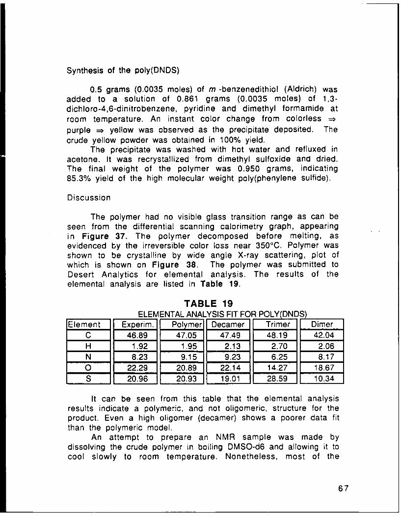
Synthesis of the poly(DNDS)
0.5 grams (0.0035 moles) of m -benzenedithiol (Aldrich) wasadded to a solution of 0.861 grams (0.0035 moles) of 1,3-dichloro-4,6-dinitrobenzene, pyridine and dimethyl formamide atroom temperature. An instant color change from colorless ==purple = yellow was observed as the precipitate deposited. Thecrude yellow powder was obtained in 100% yield.
The precipitate was washed with hot water and refluxed inacetone. It was recrystallized from dimethyl sulfoxide and dried.The final weight of the polymer was 0.950 grams, indicating85.3% yield of the high molecular weight poly(phenylene sulfide).
Discussion
The polymer had no visible glass transition range as can beseen from the differential scanning calorimetry graph, appearingin Figure 37. The polymer decomposed before melting, asevidenced by the irreversible color loss near 3500 C. Polymer wasshown to be crystal!ine by wide angle X-ray scattering, plot ofwhich is shown on Figure 38. The polymer was submitted toDesert Analytics for elemental analysis. The results of theelemental analysis are listed in Table 19.
TABLE 19ELEMENTAL ANALYSIS FIT FOR POLY(DN S)
Element Experim. Polymer Decamer Trimer DimerC 46.89 47.05 47.49 48.19 42.04H 1.92 1.95 2.13 2.70 2.06N 8.23 9.15 9.23 6.25 8.170 22.29 20.89 22.14 14.27 18.67S 20.96 20.93 19.01 28.59 10.34
It can be seen from this table that the elemental analysisresults indicate a polymeric, and not oligomeric, structure for theproduct. Even a high oligomer (decamer) shows a poorer data fitthan the polymeric model.
An attempt to prepare an NMR sample was made bydissolving the crude polymer in boiling DMSO-d6 and allowing it tocool slowly to room temperature. Nonetheless, most of the
67
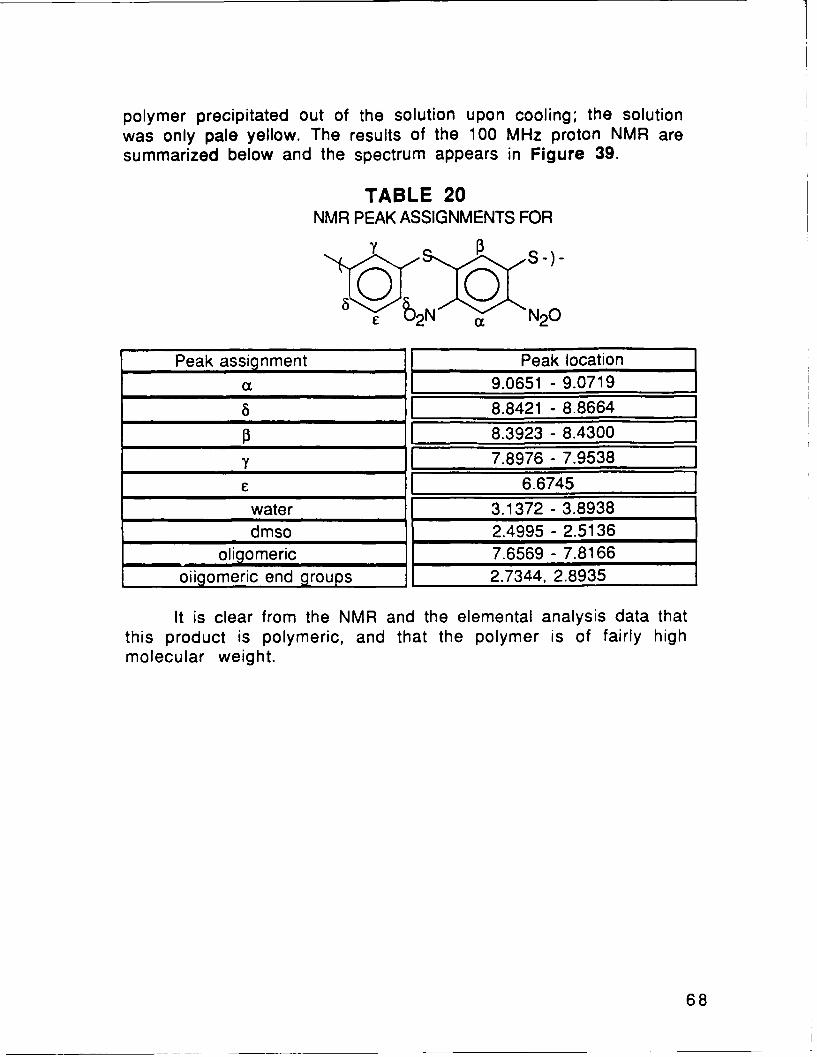
polymer precipitated out of the solution upon cooling; the solutionwas only pale yellow. The results of the 100 MHz proton NMR aresummarized below and the spectrum appears in Figure 39.
TABLE 20NMR PEAK ASSIGNMENTS FOR
Y 5-)-
0 0£ 2 N a N20
Peak assignment Peak location
o1 9.0651 - 9.0719
___8.8421 - 8.8664
i13 18.3923 - 8.4300
Y 1 7.8976 - 7.9538
16.6745water 3.1372 - 3.8938dmso 2.4995 - 2.5136
oligomeric 7.6569 - 7.8166oiigomeric end groups 2.7344, 2.8935
It is clear from the NMR and the elemental analysis data thatthis product is polymeric, and that the polymer is of fairly highmolecular weight.
68

CHAPTER 7POLYURETHANES
Alcohols I - V, described in Chapter 3, were alsopolymerized with several diisocyanates to synthesize a number ofpolyurethanes. Polyurethanes were chosen because thispolymerization reaction affords no byproducts. This fact was usedto polymerize polyurethanes under electric field. Monomeric andoligomeric species are much easier to align in the electric fieldthan long entangled polymer chains. Better dipole alignmentresults in an improved SHG signal from the polymer.
Another advantage of polyurethanes is the presence of twoamide linkages per every polymeric repeat unit, that results invery pronounced hydrogen bonding between the polymer chains.Hydrogen bonding can "lock in" the SHG useful side groups and slowdown the dipole relaxation that is prevalent in other polymericsystems utilized for SHG. 82-87
EXPERIMENTALPU SERIESPU1C15
0.033 grams (0.0002 moles) of 1,4 phenylene diisocyannate(Aldrich) and 0.045 grams (0.0002 moles) of N,N dihydroxyethyl-4-nitro-benzenamine (I) were dissolved in 5 ml of THF at roomtemperature. Four drops of the solution were carefully depositedon a microscope slide and THF was allowed to evaporate. The slidewas then placed under a sharpened tungsten needle charged at15000 volts. The sample was heated at 1000C for 15 minutes. Theheat was then shut off and the polymer was allowed to cool for 30minutes to room temperature. The electric field was thenremoved. Figure 40 shows the structure of the PU1 polyurethane.
(0,/' N' ̂ \ p4H- N NR<.n
0 0 0
NO2
FIGURE 40: PU1
PU1C13 was similarly polymerized, but under 13000 volts.Figure 41 shows a picture of the corona poling apparatus.
69

CORONA ALIGNMENT POLYMERIZATION
SHIGH VOLTAGE------- POWER SUPPLY
W CORONA r
I TEFLON BLOCKX
-VJ TEFLON SCREW FOR
"." -- FINE HEIGHT ADJUST
MVINOMFP& o
I MICRSCOPE SLIDE
HOT PLATE
RING STAND
FIGURE 41
70

PU2C150.033 grams (0.0002 moles) of 1,4 phenylene diisocyannate
(Aldrich) and 0.054 grams (0.0002 moles) of N,N dihydroxyethyl-2,4-dinitro-benzenamine (11) were polymerized as PU1C15 above.Figure 42 shows the structure of PU2 polyurethane.
- (0 1/^~ >N tY-(Q N Ny
NO2 0
NO2
FIGURE 42: PU2
PU3C150.033 grams (0.0002 moles) of 1,4 phenylene diisocyannate
(Aldrich) and 0.067 grams (0.0002 moles) of N,N dihydroxyethyl-4-(thio-4'-nitrophenyl)-benzenamine (111) were polymerized asPU1C15 above. Figure 43 shows the structure of PU3polyurethane.
0 0 0
N02
FIGURE 43: PU3
PU4C150.033 grams (0.0002 moles) of 1,4 phenylene diisocyannate
(Aldrich) and 0.076 grams (0.0002 moles) of N,N dihydroxyethyl-4-(thio-2',4'-dinitrophenyl)-benzenamine (IV) were polymerizedas PU1C15 above. Figure 44 shows the structure of PU4polyurethane.
71

0 0
NO2
FIGURE 44: PU4
PU5C150.066 grams (0.0004 moles) of 1,4 phenylene diisocyannate
(Aldrich) and 0.075 grams (0.0002 moles) of di-N,Ndihydroxyethyl-(2,4-dinitro)-phenylene-1 3-diamine (V) werepolymerized as PU1C15 above. Figure 45 shows the structure ofPU5 polyurethane.
O (YjH NHy
N02O0 0
NHNH
Figure 45: PU5
All of the PUXC13 polyurethanes were synthesized like theirPUXC15 analogues, but the tungsten needle was charged at 13000volts.
DU SERIES
DU1C150.051 grams (0.0002 moles) of diphenyl methane 4,4
'diisocyannate (Tokyo Kasei) and 0.045 grams (0.0002 moles) ofN,N dihydroxyethyl-4-nitro-benzenamine (I) were polymerized as
72

PU1C15 above. Figure 46 shows the structure of DU1polyurethane.
-F- -N0 -,
0 n
NO2
Figure 46: DU1
DU2C150.051 grams (0.0002 moles) of diphenyl methane 4,4
'diisocyannate (Tokyo Kasei) and 0.054 grams (0.0002 moles) ofN,N dihydroxyethyl-2,4-dinitro-benzenamine (11) were polymerizedas PU1C15 above. Figure 47 shows the structure of DU2polyurethane.
0~ N02
N02
Figure 47: DU2
DU3C150.051 grams (0.0002 moles) of diphenyl methane 4,4
'diisocyannate (Tokyo Kasei) and 0.067 grams (0.0002 moles) ofN,N dihydroxyethyl-4-(thio-4'-nitrophenyl)-benzenamine (111)were polymerized as PU1C15 above. Figure 48 shows thestructure of DU3 polyurethane.
73

0
S
0NO2
Figure 48: DU3
DU4C150.051 grams (0.0002 moles) of diphenyl methane 4,4
'diisocyannate (Tokyo Kasei) and 0.076 grams (0.0002 moles) ofN,N dihydroxyethyl-4-(thio-2',4'-dinitrophenyl)-benzenamine (IV)were polymerized as PU1C15 above. Figure 49 shows thestructure of DU4 polyurethane.
0NH 0
S
0 NO2
NO2
Figure 49: DU4
DU5C150.102 grams (0.0004 moles) of diphenyl methane 4,4
'diisocyannate (Tokyo Kasei) and 0.075 grams (0.0002 moles) ofdi-N,N dihydroxyethyl-(2,4-dinitro)-phenylene-1 ,3-diamine (V)were polymerized as PU1C15 above. Figure 50 shows thestructure of DU5 polyurethane.
74

0 NH(-JN FIONL% o"NO2 0
No20 0
Figure 50: DU5
HU SERIES
HU1C1533 ml (0.0002 moles) of hexamethylene diisocyanate
(Aldrich) and 0.045 grams (0.0002 moles) of N,N dihydroxyethyl-4-nitro-benzenamine (I) were polymerized as PU1C15 above.Figure 51 shows the structure of HU1 polyurethane.
0 0
<--N-(CH 2)6-Nn
0n0
NO2
Figure 51: HU1
HU2C1533 ml (0.0002 moles) of hexamethylene diisocyanate
(Aldrich) and 0.054 grams (0.0002 moles) of N,N dihydroxyethy'-2,4-dinitro-benzenamine (11) were polymerized as PU1C15 above.Figure 52 shows the structure of HU2 polyurethane.
0 0<kH N.-(C H 2) 6.-N H "O N02 h)
0 NO 2
NO2
Figure 52: HU2
75

HU3C1533 ml (0.0002 moles) of hexamethylene diisocyanate
(Aldrich) and 0.067 grams (0.0002 moles) of N,N dihydroxyethyl-4-(thio-4'-nitrophenyl)-benzenamine (111) were polymerized asPU1C15 above, Figure 53 shows the structure of HU3polyurethane.
O 0
S
0NO2
Figure 53: HU3
HU4C1533 ml (0.0002 moles) of hexamethylene diisocyanate
(Aldrich) and 0.076 grams (0.0002 moles) of N,N dihydroxyethyl-4-(thio-2',4'-dinitrophenyl)-benzenamine (IV) were polymerizedas PU1C15 above. Figure 54 shows the structure of HU4polyurethane.
O 0
SNO 2
NO2
Figure 54: HU4
HU5C15
76

66 ml (0.0004 moles) of hexamethylene diisocyanate(Aldrich) and 0.075 grams (0.0002 moles) of di-N,Ndihydroxyethyl-(2,4-dinitro)-phenylene-1,3-diamine (V) werepolymerized as PU1C15 above. Figure 55 shows the structure ofHU5 polyurethane.
-(0 N020 0
N02
a-taN(CH2)6 -1N 1-1.
0
Figure 55: HU5
77

STRUCTURE CONFIRMATION
The 1 - 4 PU, HU AND DU series samples were scraped offthe glass slide, dried in vacuo at 100 0C for 12 hours and dissolvedin DMSO-d6. The soluble fractions were filtered and collected inthe NMR tubes. The TMS reference was added in a capillary tubeand inserted into the polymer solutions. 100 MHz spectra appear inthe attached Figures 56 - 67. The peak assignments appear inTABLES 21, 22 and 23.
Another fraction of the PU polymers was submitted toDesert Analytics for elemental analysis. C, H, N, 0, and S analysiswas performed. Results are listed in Table 24.
Infrared and ultraviolet spectroscopies results appear inTable 25 and 26 and Figures 68 - 76.
PHYSICAL PROPERTIES
Thermal properties of these polyurethanes wereinvestigated using differential scanning calorimetry (DSC) on theDuPont interactive DSC. Wide angle X-ray scattering wasperformed with the finely ground powders of PUl - PU4 toreaffirm that the samples are amorphous.
HUPEG SERIES
Because absolute molecular weight measurements were notavailable, the HU series polyurethanes were copolymerized withpolyethylene glycol (PEG, M.W. = 200, Aldrich). This was done toshow that free standing polymeric films of high molecular weightare achievable at the synthetic conditions used for the SHGsamples. A range of PEG/diol compositions was copolymerizedwith the hexamethylene diisocyanate and durable flexible 50 .tmfilms were obtained for all four (HU1PEG - HU4PEG) diols.Qualitative measurements of the films' strength and durabilityappear in Table 28.
78
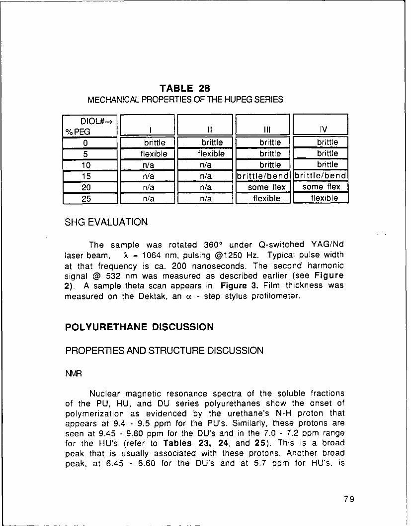
TABLE 28MECHANICAL PROPERTIES OF THE HUPEG SERIES
DIOL#--*% PEG I II I IV
0 brittle brittle brittle brittle5 flexible flexible brittle brittle10 n/a n/a brittle brittle15 n/a n/a brittle/bend brittle/bend20 n/a n/a some flex some flex25 n/a n/a flexible flexible
SHG EVALUATION
The sample was rotated 3600 under Q-switched YAG/Ndlaser beam, X = 1064 nm, pulsing @1250 Hz. Typical pulse widthat that frequency is ca. 200 nanoseconds. The second harmonicsignal @ 532 nm was measured as described earlier (see Figure2). A sample theta scan appears in Figure 3. Film thickness wasmeasured on the Dektak, an a - step stylus profilometer.
POLYURETHANE DISCUSSION
PROPERTIES AND STRUCTURE DISCUSSION
NMR
Nuclear magnetic resonance spectra of the soluble fractionsof the PU, HU, and DU series polyurethanes show the onset ofpolymerization as evidenced by the urethane's N-H proton thatappears at 9.4 - 9.5 ppm for the PU's. Similarly, these protons areseen at 9.45 - 9.80 ppm for the DU's and in the 7.0 - 7.2 ppm rangefor the HU's (refer to Tables 23, 24, and 25). This is a broadpeak that is usually associated with these protons. Another broadpeak, at 6.45 - 6.60 for the DU's and at 5.7 ppm for HU's, is
79

characteristic of the amine proton. This amine is the result of the
reaction of water with the isocyanate group according to:7 5
H20 + R-NCO R-NHCOOH =: R-NH 2 + CO2 22
The peak at 4.85 - 5.15 ppm is the unreacted alcohol peak.Another area of interest is the second type of the urethane NHproton, occuring at 8.47-8.50 ppm for the PU's, 8.52-8.67 ppm forthe DU's and 6.73-6.87 ppm for the HU series. This type of protoncorresponds to the urethanes closest to the amine in 22: R-O(CO)NH-R 2-NH 2.
Table 21 summarizes the peak assignments for the PU1-4polymers.
80

TABLE 21
NMR ASSIGNMENTS FOR TH[ PU SERIESH d d H'H H
hq R 2
j- k
NO2
Peak assignment 1 2 3 4
fgf g f g
R2,_ Hi N02 Hi NO 2k 8.00-8.06 8.46-8.66 8.04 - 8.08 8.86-8.88
_ 8.00-8.06 8,11-8.23 8.04 - 8.08 8.26-8.39
NH 9.55 9.35-9.39 9.5309 9.5370i 6.80-7.00 - 7.13-7.18 _
h 6.80-7.00 7.45-7.52 7.13-7.18 7.02-7.11oligomeric NH 8.50 8.49 8.47 8.4684
unreacted OH 4.90,4.91 4.83-4.86 5.1481 4.83-4.88- 7.36-7.40 7.36-7.40
f - 6.97-7.00 6.86-6.97d 7.34 7.24-7.36 7.3353 7.30,7.33
oligomeric CH2 3.59-3.62 3.58 3.59-3.63 3.49-3.63H20 3.4240 3.27-3.55 2.78-3.58 3.32-3.48
C 4.28-4.30 4.2863 4.22-4.29 4.27-4.28dmso 2.51,2.52 2.50-2.52 2.45-2.51 2.50-2.53
b 3.81-3.84 3.59-3.69 3.70-3.77 3.74-3.84
Similarly, Table 22 lists the NMR spectra peak assignmentsfor the HU series polyurethanes.
81

TABLE 22NMR ASSIGNMENTS FOR THE HU SERIES
Oe0b d Od
hH R 2
j-k
NO2
Peak assignment 1 2 3 4
f g f g
R2 ,E Hi 77 NO2 Hi N02k 8.00, 8.04 8.52-8.56 8.06-8.09 8.85-8.88_ 8.00, 8.04 8.18-8.24 8.06-8.09 8.32-8.41
NH 7.146 6.95-7.03 under j 7.1488i 6.88-6.92 - 7.14,7.17 _
h 6.88-6.92 7.45-7.52 7.14,7.17 7.08, 7.11oligomeric NH 6.84-6.80 6.74-6.73 6.85,6.87 under f
unreactedOH 4.87-4.88 4.76-4.83 4.77-4.81 4.81-4.85- - 7.36,7.33 7.35-7.38
f - 6.90,6.93 6.86-7.05e 4.14 4.11-4.19 4.04-4.10 4.1072d 3.70-3.71 4.54-4.59 3.61-3.70 3.60-3.63
oligomeric CH 2 3.58-3.63 d, 2.6-2.7 3.47-3.53 3.50-3.58H20 3.36 3.35-3.39 3.3485 3.3484c 2.92, 2,94 2.85-2.95 2.86-3.02 2.93-2.94
dmso 2.51 2.49-2.51 2.509 2.50-2.51b 1.32, 1.25 1.21-1.38 1.34-1.35 1.32-1.41a 1.25, 1.18 1.05-1.14 1.11-1.27 1.20-1.27
82

TABLE 23NMR ASSIGNMENTS FOR THE DU SERIES
O a O
>/ ed d e0 0 h R . o R
NO2
Peak assignment 2 3 4R1., - s- " --
f g f g
R2 -Hi N02 Hi NO 2
k 8.02, 8.06 8.54, 8.55 8.03-8.10 8.85,8.88,_ 8.02, 8.06 8.08-8.13 8.03-8.10 8.21-8.32
NH 9.54,9.59 9.35-9.45 9.56-9.81 9.58i 6.95, 6.99 - 7.11 and _ _ _ _
h 6.95, 6.99 7.47.7.51 under d under doli omeric NH 8.52-8.55 under j 8.67 8.52
unreacted OH 4.89-4.92 4.811 4.83 4.80-4.84- - /.35,under e under e
f-- 6.96-7.0 under de 7.20-7.37 7.25-7.36 7.37,under g 7.31-7.43d 7.08-7.19 7.03-7.18 7.06-7.15 7.05-7.15
oligomeric CH 2 3.58-3.72 under b 3.60-3.63 3.54-3.68H20 3.3904 3.35-3.46 3.36 3.35c 4.22-4.38 4.20, 4.28 4.27 4.27
dmso 2.50-2.52 2.49-2.54 2.51-2.52 2.50-2.54b 3.80-3.95 3.57-3.66 3.7762 3.77-3.89a under b 3.77 under b under b
Some NMR spectra show residual acetone from the tubewashing near 2 ppm. Oligomers and possibly unreacted diols
83

manifest themselves in methylenes and alcohols, locations ofwhich are described in the Tables above. Methylenes immediatelyadjacent to the alcohols are shifted downfield when a urethane isformed. This happens because the carbonyl linkage stronglywithdraws electrons.
There is excellent agreement in the aromatic/aliphaticproton ratio as seen from the spectra integrations. Even for theindividual protons there is good integral correspondence. Thisfurther asserts the polyurethane formation.
ELEMENTAL ANALYSIS
Elemental analysis was performed on the entire sample inthe PU series, not just on the oligomeric soluble fraction, likeNMR. Therefore its results are indicative of the overall polymercomposition. Results are listed in Table 24, below.
TABLE 24SYNOPSIS OF THE ELEMENTAL ANALYSIS RESULTS FOR PU's
PU#---I II Ill IV VElement theo. expt. theo. expt. heo. expt. theo. expt. theo. expt.
C 55.95 54.37 50.12 50.21.58.29 58.0953.43 53.92 51.87 51.02H 4.70 4.89 3.97 4.49 4.49 4.61 3.92 4.20 4.35 4.87
N 14.50 13.97 16.24 15.20 11.33 11.41 12.98 13.33 16.13 14.83O 24.85 26.02 9.67 29.12 19.41 19.95 23.73 24.34 7.64 9.28S .. . . 6.48 5.93 5.94 5.02 - -
Experimentally determined composition closely agrees with thelinear polyurethane structures of PUl - PU4. Side reaction 22 orcrosslinking via the biurette formation 7 4 must not occur to anyappreciable extent.
UV and IR
Ultraviolet spectroscopy of the polyurethanes shows thatthey are nearly transparent at 532 nm, the SHG frequency of theoptical experiment. Absorbance at that wavelength is detrimentalto the SHG seen from the sample. They are completely transparentat 1064 nm. This is important because if the samples absorb inthat range the sample will heat up and burn up under the powerfulNd/YAG beam. Figures 72 - 76 show the UV spectra of PU1 -
84

PU5. The transmission characteristics of these polymers at theharmonic frequency are listed in the Table 25 below:
TABLE 25TRANSMISSION OF PU's AT THE HARMONIC FREQUENCY
PU# % TRANSM. @ 520 nm % TRANSM. @ 540 nm maximum @ (nm)! 91.0 96.0 4102 65.5 88.1 4103 67.3 83.4 3804 8.4 20.1 3905 42.9 67.2 400
UV spectra of the sulfide polymers PU3 and PU4 show a sulfur tonitro n = n* transition in the 350nm range that is present in theircorresponding diols and ANDS. PU1 and PU2 absorb in 350 nm rangelike their diols, MNA and PNA. UV spectra in the near IR rangeshows that the samples are transparent at X = 1064 nm, thewavelength of the fundamental beam.
TABLE 26SUMMARY OF WAVELENGTHS (in cm-1) OF PU SERIES IR ABSORBTIONPUl PU2 PU3 PU4 GROUP PEAKS ASSIGNED TO3331 3369 3322 3316 H-bonded amide N-H3113 3092 3093 3100 sp2 C-H2947 2940 2957 2926 sp 3 C-H2894 2902 2907 2874 sp3 C-H1712 1714 1716 1718 amide1595 1602 1592 1592 amide1516 1519 1508 1517 para benzene or 1,2,4 benzene1483 - - 1459 nitrobenzene1405 1407 1405 1403 nitrobenzene1310 1329 1335 1305 aromatic tertiary amine1206 1217 1215 1214 aromatic tertiary amine1113 1145 -1110 1130 para benzene or 1,2,4 benzene1066 1063 1073 1068 nitrobenzene1000 923 1013 1007 para benzene or 1,2,4 benzene828 830 835 927 para benzene or 1,2,4 benzene752 745 750 738 amide
85

IR spectra summaries of PU1, PU2, PU3, and PU4 are listedin Table 26. All four scans show that polymerization occured.This can be monitored by the appearance of the bondscharacteristic of urethanes, such as C=O, N-H, C-O, and C-N. Onsetof the absorbtion at several wavelengths, characteristic of theamide stretches and vibrations and disappearance ofcharacteristic absorbtion of the isocyanate functionality at ca.2100 cm- 1 are indicative of the polyurethane formation.
It is difficult to see from the IR spectra whether the sidereaction depicted by 22 occurs to any appreciable extent. Theprimary aromatic amine has weak characteristic absorbtion peaksat 3400 - 3500 cm- 1 due to the N-H bond stretch. This peak ishard to detect so near the strong amide stretch ca. 3300 cm- 1 .Nonetheless, this peak is absent in all four spectra. Furthermore,10 aromatic amine absorbs at ca. 1650 - 1580 cm- 1 due to the N-H scissoring. This peak overlaps with the carbonyl stretch of theamide. These amines also absorb at 650 - 800 cm- 1 ,34 but thispeak coincides with the amide absorbtion in that region. Finally,the strong C-N stretch in 1266 - 1342 cm-1 is identical for the 10and 30 (from the nitroaniline) aromatic amines. So, IRspectroscopy is able to provide only mild evidence that 22 is nota great threat in these polymerizations.
Polyurethane formation is supported by absorbtions at(1712-1718 cm-l), (1592 - 1602 cm-l), (738 - 752 cm - 1 ) and(660 - 690 cm -1) seen in all PU series polymers. Finally,hydrogen bonded N-H and alcohol O-H are impossible todifferentiate at 3316 - 3369 cm- 1 region. 3 4 The absorbtion inthat range is most likely due to urethane's N-H, because evidencefor this bond is present at four other wavelengths. However, thereis, probably, some unreacted OH end groups overlapping with theamide stretch.
IR spectra reaffirm the polyurethane structures dictated bythe NMR and elemental analysis.
DSC
Samples showed no crystalline transitions such as meltingand only slight inflections that could be glass transitions (seeattached Figures). Because of the importance of the T9 for thedipole relaxation further thermal investigation was done. SHGsignal relaxation vs time at room and at elevated temperaturesfor each of the polymers in the PU series was monitored.
86

SHG remained constant for all samples through 1,000,000seconds at room temperature. At elevated temperatures onlyPU4C15, PU3C15 and PU1C15 were studied. Here, the corona poledsamples were heated at the designated temperature for aspecified time. SHG was then measured, and the sample returnedto the elevated temperature for the next plot point. Results arelisted in Table 31 and Figures 108 - 112. They show onlyslight relaxation at prolonged exposures at 500C and a majorsignal drop between 1000C and 1350C after 1000 seconds ofheating. This strongly suggests Tg in that thermal range.
SHG signal data at elevated temperature gives a much better"feel" for the dipole relaxation in these polymers than does theDSC. From the two, Tg's in the 100 - 1350C range are proposed.
X-RAY SCATTERING
Wide angle X-ray scattering spectra, depicted in Figures 81- 84, show a broad halo typical for amorphous materials for PU2,PU3 and PU4 polymers. PU1 diffraction shows crystalline peaks at90, 10.350, 11.10, 14.15 ° , and possibly 190. Application of theScherrer equation7 8 applied to these peaks reveals correspondingdomain sizes between 45A and 60A.
X = X/V BcorrCOSe 23
Here, x is the domain size in AX is the wavelength of the X-ray source (Ka = A)0 is the angle of a particular diffraction peakB2 corr = B2 app - B2 slit, where Bcorr is the width of
the diffraction peak, corrected by the slit width.
The size is indicative of small organic crystals, not that of thepolymer chains. This data is in line with the differetial scanningcalorimetry, which conclusively shows that the polymers arecompletely amorphous.
X-ray scattering is a very sensitive technique and it can pickup a signal from less than 1/20 (degrees) of the samplecomposition. It is possible that some unreacted diol or otherimpurity from the sample processing is responsible for thescattering peaks.
87

POLING
Conventionally, parallel plate poling has been used in theSHG field for the polymer dipole alignment. Here, a polymer film issandwiched between two parallel electrodes. The electrodes areeither transparent or opaque at the fundamental and harmonicwavelengths. If the opaque electrodes are used, then they must beremoved prior to the optical probing. A picture of a parallelplates poling apparatus appears in Figure 85.
The corona poling technique has been used in the past toproduce piezoelectric polymeric films 79 and more recently,specifically for the dipole orientation of polymer films for SHG. 1 2
The authors were able to achieve better dipole orientationand,therefore, better harmonic signal from the corona poling thanfrom the conventional parallel plates technique. 1 2
Better alignment occurs for a number of reasons under thecorona. Firstly, higher poling fields at the polymer surface areobtainable because the corona poling takes place at the voltagesnear the dielectric breakdown of air. In the parallel plate method,breakdown of the sampie typically occurs as a burn through thefilm. This happens because of the short circuiting caused by localdefects, such as pinholes and impurities. 12 Therefore, thetheoretical film breakdown voltages are not achievable in thismethod. So, the alignment is limited to lower voltages betweenthe plates. Even in good quality films this could be ten timeslower than the maximum electric field.
Secondly, conducting indium tin oxide glass (ITO), commonlyused for electrodes, is typically 300A thick. Even the minutemilliamp currents caused by the discontinuities in the film heatup and degrade the ITO at the poling voltages. This localdecomposition creates a short circuit that, in turn, draws in moreamperage and heat and burns the rest of the sample.
Thirdly, poling usually takes place at elevated temperaturesthat are necessary to elevate the polymer above its glasstransition point. Dipole movement and reorientational responsetakes place in the polymer only in that temperature range orabove. This molecular motion can create defects that are notpresent at room temperature. Defects could also appear as aresult of nonuniform sample heating that, in turn, could be causedby nonuniform film thicknesses among other things. Even if these
88

do not occur, the polymer dielectric breakdown voltage is loweredsignificantly at the elevated temperatures. 1 2
Finally, in this work, monomer mixtures were cast from theTHF solutions. The coating was never a smooth film upondeposition, and often, even the resulting polymers were notwetting the surface. Therefore, the conventional parallel platepoling was not advisable in this case.
Instead, a number of modified parallel poling methods wereattempted. One involved covering the reacting region with a thinpolyethylene terephthalate (PET) film. PET in the thickness rangeof 18 g±m to 130 Im was used. In this approach the poling voltageswere limited by the dielectric breakdown of the PET film used.Also, the choice of PET limited the temperatures to less than800C. Specific geometry of this method is shown on Figure 86.
Limits of this poling approach were not only PET's thermallimitations. The electric field was "shared" by the polyurethaneand PET according to 24:80
ET/D = t/e1 + t2/2 24
So, polyurethanes received only a fraction of the polingvoltage applied. Another limitation was placed by the top (live)electrode. A non bonded top electrode did not provide a uniformcontact across the poling area (please refer to Figure 86 in theAppendix) . This resulted in poling aberrations around the polingsurface. If the electrode was bonded to PET (as in sputteredaluminum on PET) it decomposed at voltages below 5000 volts.This resulted in a fatal discontinuity in voltage to the sample.Often, this loss of contact was not easily detectable until thesample was optically evaluated. PET could not be peeled off thesample because of the excellent bonding properties ofpolyurethanes.
This meant that polyurethane thicknesses could not bemeasured optically or profilametrically. If PET was forcefullypried off it removed the "best poled" surface of the polyurethanes.In light of these reasons, this approach was of only passinginterest.
Another poling strategy was employed by Dr. Wnek atRensselaer Polytechnical Institute . He used thin glass microscope
89

cover slips as insulators between the polymer and electrodes. Thispoling set up is shown on Figure 87. Glass plates were 100 mmthick each. The poling voltages were limited to 2000 volts by theglass dielectric breakdown strength. The effective poling fieldapplied to the polyurethane is given by 24.
If polyurethane thickness (not acurately directlymeasurable) is on the order of 50 mm and glass's dielectricconstant is assumed to be comparable to that of the polyurethane,then the effective poling field on the polymer is ca. 80,000 V/cmor between one and two order of magnitudes lower than thatattainable with the conventional parallel plates poling ofpolymers. This is unfortunate, because extra alignment, bought bythe increased mobility of poling smaller species, is negated by theearlier loss of the poling effectiveness as the polymerizationprogresses. 80 KVicm is not enough of a force to reorient largeoligomers as they condense. It is not clear how soon in the courseof the polymerization the poling efficiency is lost, because goodSHG response was obtained.
There are other non-trivial concerns about the modifiedparallel plate poling. In order to get better, more uniform andhigher polymer films better monomer mixture and more uniformmonomer deposition is necessary. This is not possible in the meltpolymerization between the plates. Better polymer films aretypically cast from solution than from the melt. The top platesever6ly limits this. Monomers could be solution cast onto the topglass slide and the solvent allowed to evaporate. However, greatcare must be taken to remove all of the solvent. Once thesandwich is made, evaporation of the trapped solvents can nottake place without catastrophic failure of the sample.
Diisocyanates are very reactive species. The chosendiisocyanates were selected (among other things) for theirtailored reactivity. Wide range of diisocyanate reactivities isavailable (see Table 2781). Some of the fastest ones are allaromatic. Chosen systems use diphenyl methane diisocyanate andpara-phenylene diisocyanate, which react very quickly.
90

TABLE 27RELATIVE REACTIVITIES FOR THE CONSECUTIVE REACTIONSOF DIISOCYANATES WITH TWO REPRESENTATIVE ALCOHOLS
RELATIVE RATE CONSTANTSDIISOCYANATE ethanol 1 -butanol
k1 kl/k2 k1 kl/k2m-phenylene - - 11 8.4p-Phenylene - - 7.7 9.24,4'-Diphenylmethane 2.3 3.2 2.4 2.92,6-Tolylene - - 2.2 6.12,4-Tolylene 3.0 25 4.9 11.93,3'-Dimethyl-4,4'-diphenylmethane - - 0.41 2.4Durene - - 0.05 2.61,5-Naphthalene 2.7 3.5 - -
1,3-Xylylene 0.2 2.5 - -
1,4-Xylylene 0.18 1.9 - -
5-t-Butyl-1 ,3-xylylene 0.19 2.7 - -
1,6-Hexamethylene 0.001 2.0Phenyl isocyanate (std) 1 - 1 -
Here, kj is defined as the rate constant for a reaction of analcohol with the diisocyanate. k2 is the rate constant for themonofunctional isocyanatourethane, formed in kj, and the secondalcohol. The reactions with ethanol were carried out in toluene at30 0C. The reaction rates of 1-butanol were measured in 401Ctoluene. All rates are relative to the phenyl isocyanate standard.Therefore, paraphenylene diisocyanate reacts 4 orders ofmagnitude faster than the hexamethylene diisocyanate.
If the isocyanates are exposed to air for a long time, theyare converted to an acid according to 22, which is not only lessreactive, but gives off water upon decomposition. This water cannot evaporate in a sandwich and destroys the sample. Incidentally,open poling systems, like corona poling, allow liquids toevaporate. This is could be useful in future "alignmentpolymerizations" that, unlike polyurethane condensations, give offwater, gas or some other liquid of polymerization.
Lack of a precise thickness measurement technique forsandwiched samples makes accurate SHG comparison impossible.
91

As can be seen from data in the present work, structural changesin the molecular design of the polymer often produce a subtlechange in SHG response, which can not be evaluated without anexact thickness measurement. Another concern in not knowing thethickness of the sample. The variation in poling ability with thefilm thickness is seen in Figure 113 in Chapter 8.
At present, it certainly seems like the corona poling is ableto optimize the benefits of the maximized orientation achieved bythe "alignment polymerization". Its advantages are numerous andit is much more open to any future system modifications.
92

CHAPTER 8POLYURETHANE SHG MEASUREMENTS ANDDISCUSSION
Several key studies were considered when thepolyurethanes were designed for SHG. The first was thecomparison of sulfide polyurethanes with the nitroanilinepolyurethanes. The second issue to be addressed was the additionof a second nitro group in the ortho position to the electron donorand its effect on SHG. Thirdly, the effect of optimizing thenumber of NLO side groups in the polymeric backbone wasinvestigated. Another issue was the effect of the poling fieldstrength on the SHG from the polyurethanes. SHG signal relaxationwas to be studied versus time and temperature. Finally, thethermally relaxed samples were to be reoriented under theoriginal alignment polymerization poling conditions and the SHGfrom these repoled samples was to be compared to the originalSHG's from the alignment polymerization.
It is appropriate to explain the role that the variouspolyurethane series (PU, DU and HU) played in this work. PU wasthe main series investigated. Paraphenylene diisocyanateprovides a very stiff hydrogen bonded urethane linkage uponreaction with an alcohol. The diphenyl methane (DU series)polymer offers a bit more flexibility by allowing an added degreeof freedom as a rotation around the sp 3 methylene link. The DUseries was prepared to see the effect of the dilution of thenumber of SHG active entities per repeat unit in the backbone. TheHU series was prepared to study the flexibility vs stiffness of thepolyurethane backbone and its effect on SHG. Table 29 shows thepolymer structures and the assigned name abbreviations. It alsolists the SHG values obtained for these thin (2-4pim) 15 KV coronapoled polyurethane films. The corresponding e - scans areincluded in Figures 88 - 102.
93

TABLE 29RELATIONSHIP BETWEEN THE POLYURETHANE STRUCTURE AND ITSSHG for 15KV corona polyurethanes in 2 - 4 im thickness range
DIISICYANATE (OCN -< >-)2CH2 OCN--INO
ALCOHOL (CH- 6(NCO) 2
tC)2 NAME: HUI DUI PUIcO2 SHG: 1.4 mV/ji 81 mV/j 178 mV/jA
EtOH)2 NAME: HU2 DU2 PU2N02 SHG:HU 36 mV/ 48 mV/
N02
(tO H)?
NAME: HU3 DU3 PU3
S HG: 9.0 mVjI 21 mV/ji 40 mV/jA
N02
N5EtOH)2
1 V NAME: HU4 DU4 PU4
S HG:NO2 21 mV/j 61 mV/pI 52 mV/p
NO2
02N N(EtOH) 2 HU5 DU5 PU5~NAME.
SHO: none 67 mV/p 14 mV/p02N N(EtOH) 2
94

At the time of this work, absolute SHG measurements, suchas X2 or d3 3 , were not available for films thinner than a coherencelength. Normally, for the thicker films, coherence length can beobtained from a Maker-fringe experiment. 6 Since no fringes areseen from thin films, using optical waveguiding techniques1 2
were used previously to measure the refractive indexes of theharmonic and the fundamental wave.
As a reference, several commonly used materials weremeasured for SHG in the present system. These results appearbelow:
TABLE 30REFERENCE SHG MATERIALS
MATERIAL SHG SIGNALQUARTZ 15 mV
POWDER KDP 40 mVPOWDER UREA 34 mVPOWDER ANDS 750 mVPOWDER MNA 1500 mV
A) Relaxation Studies
Table 31 shows how some of the po'yure.hane samples losttheir SHG efficiency after prolonged exposures to elevatedtemperatures. At room temperature all of the polyurethanes in thePU series showed no signal decay over the first 106 seconds oftheir life, see Figure 106. Dipole alignment relaxation of poledpolymers at temperatures near glass transition is welldocumented in the literature.1 0 , 1 1 , 12 , 8 2 ,8 3 In this thermal range,molecular motion of the macromolecules is allowed. This viscousflow is utilized in the conventional poling processes.
95

FIGURE 106SHG SIGNAL RELAXATION FORPU's AT ROOM TEMPERATURE
200
EE. . PU1
E
100U.0
0 PU4
* PU2
Pu
0P0 2 4 6
log(time) secs
TABLE 31DIPOLE ALIGNMENT RELAXATION IN THICK POLYURETHANES
POLED AT 15 KV AS A FUNCTION OF SHG (mVIg)
TRTMNT, NONE 106 sec 104 sec 103 sec 103 secPOLYMER @ RT @500C @1000C @135 0C
PUl 178 178 128 12 0.3PU2 48 48 n/a n/a n/aPU3 40 40 n/a n/a n/aPU4 52 52 43 36 1.9
At room temperature, synthesized polymers were well belowtheir Tg's and dipoles were "frozen in". In practice, however, somerelaxation does indeed take place. This is the most obvious in theSHG systems where the active entities are small polar guestmolecules, such as MNA, dissolved in a transparent polymermatrix, such as PMMA. Hampsch and coworkers8 4 observed a 80%signal drop in just 10 hours. Their system was 4% DANS (4-dimethylamino-4'-nitro stilbene) dissolved in PMMA. After
96

0.5x10 6 seconds at room temperature the harmonic signal decayedvirtually to zero.
Marks and coworkers, in an attempt to improve the SHGrelaxation parameters, dissolved DANS in an optical grade epoxyresin. Here, the SHG signal decreased down to 40% of the original
in the 3.6x10 6 second time span. 8 5 Amorphous polymers withcovalently bonded NLO side groups performed a bit better, but stillshowed appreciable dipole relaxation at room temperature. 85,86
This is why the temporal performance of the studiedpolyurethanes is so encouraging. At 500C after 10,000 secondssamples lost 17 - 28% of their original SHG efficiency, indicatingthat some dipole relaxation was slowly taking place. This is insharp contrast to Meredith's work that examined the SHGrelaxation at elevated temperatures. 8 7 Meredith's systemconsisted of DANS trapped in a "polymeric cage" of a thermotropicnematic liquid crystalline host. Its SHG signal relaxed to 1.5% ofthe original at 500C.
After 1,000 seconds at 1000C, almost 3/4 of the signal losswas recorded, showing that the original anisotropy in the samplewas mostly randomized due to diffusion. Finally, the exposure ofthe samples to 1351C completely averaged out all preferedorientation in the linear polyurethanes. Conversely, thecrosslinked samples, such as DU5C15, did not lose any of theinduced orientation even after a 1000 second heating at 1200C;please refer to Figure 107. Figures 108 - 112 shows howsome of the polyurethanes relaxed their dipole alignment aftervariable time exposures to 1000C and 500C.
97

FIGURE 107DU5 SHG SIGNAL RELAXATION AT 120*C
S 70-
68 j
66Z 4 3 DU5
I- 64
, 62
0 1 2 3
U, log(time) secs
98
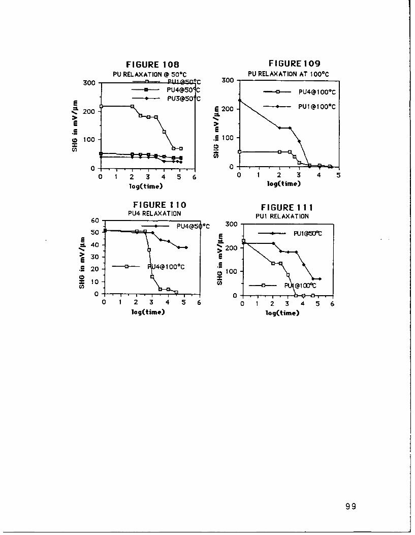
FIGURE 108 FIGURE 109PU RELAXATION @ 500C PU RELAXATION AT 100C
300 1 13 "C 300 /-i--PU4@50C--- [email protected] PU3@50 'C
6200- PUI@100C200
*i I
100 .0 100
o4,, 0
0 1 2 3 456 0 1 2 3 4 5
log(time) log(time)
FIGURE 110 FIGURE II1PU4 RELAXATION PUI RELAXATION
- PU4@5 0 C 30050 -E • ItI x13cd
=. 40 200
30 -
*~20~4@100C P100=10 =
0 . . . . . . 0 -- f
0 1 2 3 4 5 6 0 1 2 3 4 56log(time) log(time)
99

FIGURE 112
TIME AND TEMPERATURE DEPENDENT SHGRELAXATION OF THE PU SERIES POLYMERS
300
E PU4@100°C
Pu1@100°CE 200E PUI@50°C
0 PU3@500CU) PU4@500C
100
30 1 2 3 4 5 6
log(time)
These data, combined with the DSC results, indicate glasstransition in the 100 - 135 °C range for the para-phenylenepolyurethanes.
B) POLING FIELD EFFECT
Poling electric field strength has a great effect upon thedegree of alignment of the polymers. In traditional polymer polingto obtain piezoelectric films or for SHG, usually a saturationlevel was reached where increasing the voltage did not result inimproved orientation as indicated by the leveling of thematerials' non-linear response. 12 In these processes the polymerfilms, spun on substrates, were heated above their Tg's under theapplied voltage.
In present work, polymerization proceeded under the polingvoltage. This means that a monomoric mixture, not d polymer,was cast on the substrate. When heat and corona were appliedtwo competing processes could have taken place. The first is thedesired dipole alignment during the course of the polymerization
100

due to the field. The second process electrostatically chargessmall monomeric particles and disperses them under the needle.This results in a blank spot directly under the needle, where theSHG signal should be optimal upon the completion of poling.
Clearly, good alignment during polymerization must beoptimized by minimizing this effect while maximizing the dipolealigment. SHG saturation voltage conditions were studied indetail for all PU series polyurethanes.
These studies were complicated by several factors. Firstly,the maximum corona voltage is limited ultimately by thedielectric breakdown of air around the tungsten needle. Dielectricstrength is influenced by humidity and temperature. For instanceat the distances of 2-3 mm between the corona tip and thesample, voltages of up to 20KV could be produced at roomtemperature without arcing. In the 100oC-1 100C range thisvoltage drops to 15KV-17KV. At 3000C, only 7KV levels could bereached.
Air breakdown results in an ionized glowing purplish bluecloud that arcs to the ground. With voltages above air breakdownstrength the size of the "clouds" grows and the arcs are able toreach farther and farther.
Another important factor needs greater understanding atpresent. There appears to be a dependence of the poling efficiencyon the sample thickness. With the thicker samples the degree ofalignment seems to decrease. Figure 113 shows the drop of thepoling efficiency with the increasing sample thickness asmonitored by the SHG response of PU1C15. The dependenceappears to be linear for PVIC15 polyurethanes.
101

EFFECT OF THE FILM THICKNESS ONTHE CORONA POLING EFFICIENCY
300'SHO = 268.85 - 27.898t
E
200
U)U
z-
U)-J-
r 0-oo 0 2 4 6 8 10
FILM THICKNESS (um)FIGURE 113: EFFECT OF THE FILM THICKNESS
ON SHG DENSITY OF PUl 15
Since the entire reacting surface is radially charged aroundthe corona tip, there is a strong radial SHG signal dependence. Itdoes not appear that corona poling of these polyurethanes is solelya surface alignment technique. If that were the case, the SHGvalues would be approximately the same for samples of allthicknesses.
For these reasons, all samples studied were in the samethickness range. The results appear in Table 32. There is aremarkable drop from 15 KV to 13 KV for all PU polymers and at10 KV the polyurethanes studied showed virtually no harmonicsignal. Because of static charging and arcing at 1000C, it was notpossible to raise the poling voltage above 15,OOOV. Therefore, thecommonly observed saturation of the non-linear effect is not seenhere.
102

TABLE 32EFFECT OF THE POLING FIELD STRENGTH ON SHGOF THIN PARAPHENYLENE POLYURETHANES (PU'S)
CORONA 15,000 13,000 10,000POLING FIELD VOLTS VOLTS VOLTS
PUl 178 mV/. 78 mV/g n/a
PU2 48 mV/. 15 mV/g n/aPU3 40 mV/p. .5 mV/p. n/aPU4 52 mV/g 12 mV/g n/aPU5 14 mV/p. mV/g 0.41mV/p
Samples of PUL1C15 and PU4C15 were thermally relaxed at135 0 C for 15 minutes. There, the anisotropies were thermallyremoved as indicated by the disappearance of the harmonicresponse at 532 mm. The samples were repoled at 1350C and15KV for 15 minutes. The heat was shut off and the samples werecooled to room temperature under the E-field. After 45 minutesthe E-field was removed. The samples were rotated under apulsed YAG laser as described previously. The results of thesescans appear in Figures 103, 104 and 120.
The signal from these samples was drastically (40-80%)lower than that from the alignment polymerization. Results arelisted in Table 33. These results indicate that the alignmentpolymerization provides particularly superior dipole alignment tothe conventional poling with the stiffer polymeric backbones. Forinstance, DU1C15 shows ca. 40% SHG improvement with alignmentpolymerization, while more rigid alignment polymerized PU1C15shows over 5 times stronger SHG than its conventionally poledcounterpart.
In light of the need for stiff, high Tg polymers for thermallyand temporally stable SHG, these results appear especiallyattractive.
103

TABLE 33COMPARISON BETWEEN THE ALIGNMENT POLYMERIZATION
AND THE CONVENTIONAL POLING SHG's, 15 KV CORONAS
POLYURETHANE STRUCTURE ALIGNMENT CONV.POLYMERIZATION SHG POLING SHG
178 mV/p. 35 mV/p.N02
o n52 mV/g 25 mV/g
N09
-(OCH2CH2-NCH2CH20L",,-Ho -IT[ 0 '-0 67 39mV/p.Y mV/gNO2
It is interesting to note here that the SHG signal from thePUlC15 repoled was much stronger than the one from PE1C15(FIGURE 104) prepared under similar conditions (35 vs 9.6 mV/p.,Table 34).
104

TABLE 34POLYESTERS VS POLYURETHANES FOR SHG
POLYMER STRUCTURE SHG
-(O \ /\/ n
09.6 mV/
N0 2
PE1 C1 5-"REPOLE"
(0\/-7s Q - N
N02 35 mV/p.
PUl C1 5-"REPOLE"
This could be attributed to two phenomena. Firstly, in theurethanes better dipole alignment is possible because of thehydrogen bonding in the urethane linkage. This bonding can beresponsible for better "locking in " the urethane C=O dipoleparallel to the nitroaniline dipole. In these polyurethanes thereare two C=O linkages per every nitroaniline. So, ultimately, thereare two carbonyls contributing for SHG along with everynitroaniline.
Secondly, the two added sp 3 nitrogens in the urethanerenders the carbonyl dipole more flexible with respect to thebackbone above Tg. Also these spacers in a fairly stiff aromaticbackbone could help the mobility of the nitroaniline by renderingthe whole chain more flexible above Tg. Finally, the hardsegment/soft segment model of PUs can be enlisted to summarizethe role of the hydrogen bonding "locking in" the dipole orientationbelow Tg.
C) Effect of the Second Nitro
105

Table 35 summarizes the effect of the addition of thesecond nitro group in the ortho position to the electron donor. Inthe DU15, PU13, and PU15 series a general drop in SHG is observedupon addition of the second nitro group. The most dramatic drop isseen in PU1C13 -* PU2C13 (78 - 15 mV/p., 81%). PU1C15PU2C15 shows a 73% drop (178 -- 48 mV/p.). DU1C15 -4 DU2C15decreases the harmonic signal 56% (81 -4 36 mV/p).
TABLE 35COMPARISON OF THE SHG'S (mV/p.) FROM THE
MONO AND DINITRO POLYURETHANESSUBSTITUENT ANILINES SULFIDES
DIOL#-' 1 II ill IVPOLYMERS
HU15 1.4 8.2 9.0 21
DU15 81 36 21 61PU13 78 15 6.5 12PU15 178 48 40 52
These results were counterintuitive; one would expect auniversal increase in SHG upon addition of a second nitro group dueto an increased dipole moment in the dinitroanilines. Thiscertainly was the intention behind the molecular design. However,recently published 0 measurements of dinitroaniline 90 show thatthe polarizability of this molecule (21 x 10-30 esu) is roughlyhalf of that of the p-nitroaniline.
Upon a closer examination of these polyurethanes, arelationship between the stiffness of the polymer backbone andthe SHG drop due to the second nitro group can be established. Asmentioned earlier, paraphenylene polyurethane has the stiffestbackbone of the polyurethanes in the present study. The addition ofthe second nitro group to create the 2,4 dinitro aniline not onlyincreases the dipole moment of the molecule; it also rotates thedirection of the dipole moment. This new net dipole direction is atan odd angle to the chain. Stiff chains can not sterically allow aperfect alignment of these dipoles.
106
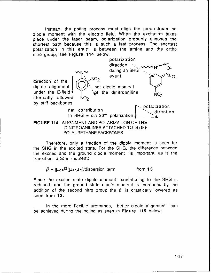
Instead, the poling process must align the para-nitroanilinedipole moment with the electric field. When the excitation takesplace uider the laser beam, polarization probably chooses theshortest path because this is such a fast process. The shortestpolarization in this entit, is between the amine and the orthonitro group, see Figure 114 below.
polarizationdirection - . ,
,N-,& during an SHG'- -,'!1 NO event " 'O-
direction of the N02
dipole alignment .. net dipole momentunder the E-field O r 4of the dinitroaniline NO2sterically allowed NO2by stiff backbones
'. polazationnet contribution directionto SHG = sin 300* polarizaticn dei
FIGURE 114: ALIGNMENT AND POLARIZATION OF THEDIN!TROANILINES ATTACHED TO S IFFPOLYURETHANE BACKBONES
Therefore, only a fraction of the dipolp moment is seen forthe SHG in the excited state. For the SHG, the difference betweenthe excited and the ground dipole moment is important, as is thetransition dipole moment:
= --Igel2 (p9e-pg)/dispersion term from 1 3
Since the excited state dipole moment contributing to the SHG isreduced, and the ground state dipole moment is increased by theaddition of the second nitro group the /3 is drastically lowered asseen from 13.
In the more flexible urethanes, better dipole alignment canbe achieved during the poling as seen in Figure 115 below:
107

E-field N,
moment
,* polarization
02 N / directionN20
FIGURE 115: ALIGNMENT AND POLARIZATION OF THEDINITROANILINES ATTACHED TO
FLEXIBLEPOLYURETHANE BACKBONES
Even if the transition state and the excited state dipolemoments are solely directed by the amine --+ ortho nitropolarization, the SHG contribution from them is larger than thatfrom the similar polarization in the stiff chains.
As the stiffness is relaxed and more flexibility is allowedthe signal loss is lessened. This is seen in going from theparaphenylene to the diphenyl methane polyurethanes (PU -- D!J).PU1C13 --+ PU2C13 shows the biggest drop because 13,000 volts isnot as sufficient to "fight" the polymer stiffness as 15,000 volts.The electric field does "fight" the stiffness; in poling the polymerin a sterically impossible direction, the stiffness of the chainworks against you, not for you.
Hexamethylene series (HU's) have a very flexible all-sp 3
backbone. These chains can adapt to the odd angles of thedinitroaniline dipoles. As a result, a large increase is seen in SHGof HU1C15 -- HU2C15 (1.4 --* 8.2 mV/p.).
In the sulfides, there is a net increase in SHG when a secondnitro group is added. Unlike the nitroaniline polyurethanes, theseside groups have an added degree of freedom around the sp 3 sulfur.Therefore, they have an ability to rotate to perfectly adjust to thenew dipole moment direction. The amount of the increase of SHG isin general agreement with the decrease of the chain stiffness.
D) Role of Sulfur
108

In the mononitro compounds, the insertion of a thiophenylgroup between the nitro group and the aniline ring drasticallyreduces the SHG response. (See Table 36) This effect is evidentin the paraphenylene polyurethanes poled at 15,000 V and 13,000V and also in the diphenyl methane urethanes. The HU seriessynthesized with the more flexible hexamethylene diisocyanatesshowed a dramatic increase in the second harmonic response.
TABLE 36COMPARISON OF THE ANILINE AND SULFIDE
POLYURETHANE SUBSTITUENTS SHG (in mV/g).[ MONONITRO DINITRO[SUBSTITUENT________________________
DIOL#-* I III II IVPOLYMER .I I .... __.
PU15 178 40 48 52PU13 78 6.5 15 12DU15 81 21 36 61HU15 1.4 9.0 8.2 21
The largest SHG drop was seen in PU1C13 -+ PU3C13 (786.5 mV/p down 92%). The second largest drop was observed inPULC15 -5 PU3C15 (178-*4OmV/!. down 78%) . In the DU series,DUIC15 -- DU3C15 the signal drops from 8lmV/g -* 2lmV/.down 74%. Finally, in HULC15 -- HU3C15 an increase is seen; 1.4-* 9.0mV/p. up 543%. The trend here is, once again, that with theincreasing stiffness of the backbone, the SHG drop increases inanilines vs diphenyl sulfides.
This happens because the nitroaniline entity in the U1 serieshas a dipole moment which is more orthogonal to the backbonethan that of the sulfides. In stiffer chains ideal alignment of thesulfide dipole moment parallel with that of the carbonyls becomesimpossible. Here, again, the stiffness of the backbone works"against you". Nitroanilines are easier to align parallel to thecarbonyls, so that the dipole moments add up constructively. Inthe very flexible hexamethylene urethanes parallel alignmentbecomes possible and as a result an SHG increase is seen. Finally,[3 of p-amino-p'-nitro diphenyl sulfide group, 27 x 10 .3 0 esu, is
109

abot 25% lower than that of the nitroaniline (35-42 x 10-30 esu).This also lowers the SHG of the sulfide polyurethanes compared tothat of the similar nitroaniline polymers.
HU series polyurethanes have a completely unsaturated sp3
backbone that results in HU1, HU2, and HU5 polyurethanes beingnear their glass transition at room temperature. This is indicatedby viscoelastic behavior that can be visually observed in the HU's.Another problem with the HU series is the lower reactivity ofhexamethylene diisocyanate vs that of its aromatic counterpartHexamethylene diisocyanate is a liquid at room temperature withhigher volatility than the solid paraphenylene and diphenylmethane diisocyanates. Combined, these two reasons probablyresult in a lower molecular weight polyurethanes due to an upsetstoichiometry.
The diphenyl sulfide bearing HU urethanes (HU3 and HU4)have a stiffer SHG side group than HU1, HU2, and HU5. In light ofthe flexibility of the sp 3 backbone, this stiffness of the diphenylsulfides begins to cominate the SH behavior of the polyurethanes.
In the dinitro polyurethanes similar chain stiffness effectsare observed. In the PU series, PU2C13 (15 mV/p ) and PU2C15(48 mV/p.) show SHG signal comparable to that of PU4C13 (12mV/p.) and PU4C15 (52 mV/lp), their dinitro counterparts,respectively. DU4C15 shows an increased signal over that ofDU2C15 (61 mV/. *-- 36 mV/l., up 69%). HU4C15 (21 mV/p)shows a marked improvement over HU2C15 (8.2 mV/ft, up 149%).
In the stiffest paraphenylene urethane chains,dinitroanilines are comparable to the dinitro sulfides in theirharmonic response because both offer active dipole moments at anodd angle to the backbone. It is also sterically impossible to alignthe active dipoles parallel to that of the carbonyls. The addeddegree of freedom, afforded by the rotation around the sulfur inPU3 does very little to improve the alignment of the dipole andpolarization direction parallel to the electric field. In PU4,however, better alignment of the polarization direction with theE-field is possible because of the polarization to the ortho nitroas seen in Figures 114, 115 and 116. Unfortunately, as seen inTable 25 in Chapter 7, PU4 absorbtion is much greater than thatof the other polyurethanes (I-Ill) in the green region. Therefore,
110

there is virtually no SHG difference between the two types ofurethanes.
N
E -field lS
direction
polarization02N 0 \ direction available in PU4
N20
FIGURE 116: PU4 POLARIZATION UNAVAILABLE FOR PU3
111

It could be argued that a slight drop in PU13's and a slightincrease in PU15's could be related to the increasing ability toalign the active groups with the higher electric field. Rather thanasserting this fact, it should be pointed out that the effect is soslight that it is within the error range of the experiment.
As in the mononitro compounds, the added flexibility of theDU backbones sterically allows a better alignment of the SHGgroups in the electric field. This results in an increased sulfideharmonic response vs that of the nitroanilines. Here, once again,the flexibility issue dominates the harmonic response. Sulfidesare better able to align the dinitrobenzene dipole moments due toan added degree of freedom provided by the rotation ability aroundthe sp3 sulfide. This does not do much in the PU4C15 and PU4C13because the sulfur rotation alone can not bring the dipolealignment. However, in the diphenyl methane urethanes it iscoupled with the rotational ability of the methylene link anddipoles are sterically alignable.
In the HU2C15 -) HU4C15 a 149% increase can also beattributed to the stiffness of the diphenyl sulfide group in thevery flexible backbone. This stiffness helps to preserve the dipolealignment and slower the relaxation process in the HU sulfides.
E) Density Study
FIGURE 117EFFECT OF THE SHG ACTIVE GROUP DENSITYIN THE POLYMER BACKBONE ON SHG
200
E
100 PE DU,z Iv .
~IIIV
0~10 20 30
NLO GROUPS/# atoms
112

Figure 117 shows the attempt to relate the magnitude ofthe SHG from the polyurethanes with a number of the NLO non-contributing atoms (those that do not have attached NLO sidegroups) in the backbone. This number is 15 for the PU series and20 for the DU's. The dependence of the harmonic response on theNLO group density is difficult to measure across the board withall three polyurethanes, PU's, DU's and HU's. The HU series has tobe discounted here because of the molecular weight issue thatarises due to the reasons mentioned previously. This results in PUurethanes near their glass transition at room temperature. TheSHG signal quickly relaxes at room temperature for the HU's.
This leaves only two points on the density plot, that of thePU15's and DU15's. The only pronounced difference between theseries shows up in PUIC15 (178 mV/p) and DU1C15 (8lmV/.).Other corresponding PU15 - DU15 urethanes show comparablesignals.
In light of these data, it appears more productive to work onthe SHG optimization by maximizing the polarizability of theactive group and the alignment of its dipole moment rather thanmaximizing the number of atoms with the SHG active groups in thebackbone. However, once this optimization is achieved, as inPUIC15, the density effect becomes more pronounced. Clearly,more data points are needed on this plot before any conclusionscan be drawn.
113

CHAPTER 9FUTURE WORK
Optimization of the second harmonic response from thepolymers can be approached from several directions. The presentlydescribed alignment polymerization systems can be improved by amore uniform film deposition and by reactivity tailored poling.Synthetic improvements fall into two categories. Firstly, theexisting synthetic conditions can be modified to yield highermolecular weight polymers, especially in case ofcyclopolymerizations, polyesterifications and poly(ANDS)condensations. Secondly, the active "ingredients" can be modifiedto produce altered polymers with possibly increased molecularweights or increased harmonic response.
Thirdly, a more uniform polymeric dipole alignment ispossible with several variations of the corona poling. Only arelatively small radial polymeric region below the corona tip isoptimally aligned. If the corona discharge takes place from asharp edge of a wire instead of a point source, a narrow polymericstrip is aligned. Furthermore, this approach can be extended to agrid of coronas. Here, an array of strategically positioned pointsources of voltage create overlapping radial polymeric regionsthat span the entire film surface. If the corona poling apparatus isenclosed in a sealed container filled with gas, which has higherdielectric strength than air, the breakdown will occur at highervoltages. This might result in increased dipole alignment.
During the alignment polymerization of urethanes, the polingvoltage can be ramped with the temperature. As mentioned inChapter 7, the dielectric breakdown of air takes place at lowervoltages as the temperature is increased. Consequently, if thevoltage is increased as the heat is shut off in the polyurethanepoling, slight SHG improvement could be seen.
Similarly, if the polymerization of urethanes is carried outwith the tailored reactivity diisocyanates, then specific voltagevs temperature and time profiles can be developed for eachpolymeric system. The importance of optimizing the diisocyanatereactivity was demonstrated in Chapter 7. If the diisocyanatereacts too slow, then the side reactions with water and otherimpurities become increasingly important.
If it reacts too quickly, then the polymerization will takeplace too early, either in the monomeric solution prior to thedeposition or as the solvent evaporates. In both cases,
114

polymerizations occur prior to the application of the aligningvoltage. Certainly , more diisocyanates need to be examined tobetter balance the reactivity tradeoffs.
More solvent systems should be evaluated for bettermonomer deposition. Presently, uniform films are very difficult toobtain from the alignment polymerization. This is because fourdiols (I-IV) and the tetrol V display a surprisingly wide array ofsolubilities. In particular, IV was especially difficult to dissolvein THF. A high volatility solvent capable of high diol anddiisocyanate solubility will deposit a more uniform monomericcoating, yielding a smoother polymeric film.
Another polyurethane SHG improvement can be brought aboutby using a diisocyanate with an SHG active group. For instance, N,Ndi(2-isocyanatoethyl) 4-nitroaniline can be obtained:
HOO
NO \ 1 --- O C I .. -.. N -- C I OCN .. - NOD)
0 2 Cl. ClI 2 NaOCN
0
NO2 NO2 NO2
FIGURE 118: SYNTHETIC ROUTE TO A NLODIISOCYANATE
The first part of this synthesis has been successfully carried out,as described below. The second stage is readily obtained from theliterature8 8 is a standard route to isocyanates. This diisocyanatedoubles the SHG active group density in the polyurethanes andhopefully further improving the polymer harmonic response.
Diamines have been prepared from the I diol according to:
115

HN OH Ci CIN O
H2, -N ,,,,2 N HK0 0
NO2 NO 0
00 0
NNO2
NO2 0NO2
FIGURE 119: SYNTHETIC ROUTE TO A NLO DIAMINE
This synthetic route was proposed and carried out by DrWei. 8 9 He had difficulty isolating the free amine in the lastreaction step. When the free amine is obtained, it can be used toprepare nylons, polyimides and epoxies.
The new polymeric systems not only expand the range ofpolymer classes for SHG, they provide an interesting intermediatebetween the polyesters and polyurethanes in the polyamides. Withthe NLO polyimides, a new class of thermally stable SHG polymersis insured. Finally, epoxies will provide another class of thecrosslinked polymers with permanently aligned dipoles. As anadded benefit, these new classes will provide more data on theeffect of increasing the SHG group density in the polymerbackbone.
Also, if the conditions for cyclopolymerization of VI and VIIare determined, yet another class of linear SHG polymers with ahigh density of NLO groups will be obtained. Thesecyclopolymerization conditions must exist because a crosslinkedproduct was readily obtained at higher temperatures.
116

Finally, poly(ANDS) is only one synthetic step away fromfruition. Poly(DNDS) synthesis proves the feasibility ofpoly(ANDS) polymerization. Both poly(ANDS) and poly(DNDS) shouldbe excellent SHG polymers, if either their crystallinity isdisrupted or utilized for the phase matching. Certainly, theywarrant more work because of their superb SHG potential.Similarly, more effort in polymerization of poly(ANDS vinylene)will bring equally high dividends.
In conclusion, it is interesting to point out that molecularengineering of polymers for SHG, and polyurethanes in particular,brought very satisfying results. The corona alignmentpolymerization yielded excellent results. It yielded significantlyhigher SHG values than the conventional corona poling in all of thepolymeric systems tested.
At the same time it provides an unique tool for dipolealignment of the rigid backbone polymers. Such aromaticpolymeric systems offer temporal and thermal SHG longevity thatwas lacking for this class of materials before. High Tg polymersare almost impossible to align via conventional corona or parallelplates poling, because of the high temperatures required. Coronaalignment polymerization offers the only way to efficiently polethese polymers. It definitely has high potential for other NLOpolymerization systems. It can also be extended to ceramicsystems, such as sol-gels.
117

APPENDI(
FIGURE 10: NMR of B FIGURE 1 1: NMR of C
FIGURE 12: N>IR of D FIGURE 13 : NMR of E
/ .1 7
FIGURE 14: NMR of F
FIGURE 15: NMR of G
118

FIGURE 18: NMR of I FIGURE 19. NMR of 11
11
FIGURE 22: NMR of V~

FIGURE 2 4 NM R t IFIGURE 25~ NMR of VII
F I G URE 27: N>! P f D iphn 1 u ~ 11 V ~ c
1 20

FIGURE 29: N1M. of 2,6-dinitro- FIGURE 30: NMhR of 2,5-dinitro-
1,4-dichlarobenzele i,4-dichlorobelzene*2dioxale
F'IGURE 3 1: NMofclean 2,5-dinitro- FIGURE 32: N"MR of~ 1,3-dichlor)
1,4-ichorobnzee 46-dinit rob enzene
4 1
FIGURE 33: NMR of 1,2-diclhloro-4,5-diflitrobenzenQ 121

-fl~TR
.3 .I .....J
44-AI
FIGURE 3: DSGR o f Po-dlDND FIGURE 3& M4 of Poly(DNDS)
4'-ntro ipheyl slf22

FIGURE 56: NMR of PUl FIGURE 57: NMR of PU2
KK
. . .S . "
FIGURE 58: NX R of PU3 FIGURE59 : NMR of PU4
123

FGR60 -R0fHUI FIGURE 61: NmR of HU2
a :~ , I .. ,.i~ l~P2 .........
.~.. .- ..
£~~~ ~ ..........-g ,I.,,
FIUE62 NRof HU3 FIGURE 6 3: NRof HU4
124

FIGURE 64: NMR of DU3 FIGURE 67. NR of DU
~~125

13 1:(21 V MA N B3E (,KIV A N
'33 ... .. .
.. ... .. .. . S
sl as S &S* r(
ii5
Z .. . ...... ..
FIGURE 68: IR Spectrum of PU3 FIGURE 69i IR Spectrum of PU4
BECKM126

- -----...... . .00..o
FIGURE 72: UV Spectrum of PUl FIGURE 73: U V Spectrum of PU2
... .... .
... .. ... . .. . . . .
.~~~~~~~S ..... . .......... . .. . . .. . . .. . . .. . . . ..... .
FIUR .U Sp.tu of .U3 FIUR 75 UV Spctu of .P.. . . .......
. 0 ._ _._._._._..._._._._ _._._._._._._._._._.
. .... .. ... .. ... .. ... .. ...
.0 . .* .
FIGURE 74:UV Spectrum of PU5 12UE7: VSetrmo U
.... . ... ... .. .. . .. ..7

S..1I. pul-93 0.4. a--0 .. I 0.3 S. . 02. 0.F:.. Put .- 6 ,.. *.
A...~ OsW O63.II6 0,1.4 ILIA-6
0
-24
FIGURE 77: DSC of PUl FIGURE 78: DSG of PU2
S-pl.. 0512.I 666106... 6.2L $1 0-6- I.-4611 T-. 3.34.s 2- k e COSC ,-I ILIA.0 T SA
$I. IL2P it. P1.11111 TULtSA -o4
IV6t.4. 22 s 01.-4-.. ILYA 1 ..4....6.. OWC V26 p6.kt.4. I - as-6 4.2&P-9-. .(... Ls 03 0.60.tk4 l-J..--411 3.410,811
-0 20
2.4 1. g
FIGURE 79: DSC of PU3 FIGURE 80: DSC of PU4
128

to iI:~ 1' Fri- - 7
FIGURE 81: SAX from PUl FIGURE 832: SAX f rom, PU2
J;:__ __ 1. 1,1,1 1..
LL- _.__
- -- n -0-:10
FIGURE 83- SAX from PU3 FIGURE 84: SAX from PU4
129

FIGURE 85
PARALLEL PLATES POLING
+ HiGH VOLTAGE
POWER SUPPLY
-" ITO GLASS - I-
ITO GLASS
HOT PLATE
RING STAND 7
130

FIGURE 86
PARALLEL PLATES ALIGNMENTPOLYMERIZATION WITH PET
i HIGH VOLTAGE
....... POWER SUPPLY
TEFLONPRESS
UVE ELECTRODE
--- 7 PET FILM
MONOMERS
(TO COATED GLASS
HOT PLATE
II
RINGSTAND
131

FIGURE S7
PARALLEL PLATES ALIGNMENTPOLYMERIZATION, WNEK METHOD
__ HIGH VOLTAGE-----.- POWER SUPPLY
AJELECTRODE IGLASS COVER SLIP
mIo
GLASS COVER SLIP
-++ Al ELECTRODE +++
HOT PLATE
RING STAND
132

e m *. t"I -
FIGURE 88- SHG from FIGURE 89: SHG from PU2CI5PUIC15
FIGURE 90: SHG from PU3CI5 VIGURE 91: SHG from PU4CI5
.. i - ",
'\
'
FIGURE 92: SUG from PU5Cl5133

FIGURE 93: SHG from DUIG15 FIGUJRE 94: SHG from-DU2C15I -
FIGURE 95: S HG f ro m t-3C1 5 FIGURE 96: SHGC from DU4C1 5
134FIGUER997: SIG from DU5C 5

, ~~~~~ii ' . . ,,. . .i 1 f
I V
FIGURE 98: SMfG from FIGURE 99: SHC from HU2C15
HU1C15
ii / ,! \
FIGURE 100: SHG from FIGURE 101: SHG from HU4C15
HU3C15
135
FIGURE 102: StlG from ttU5CI5
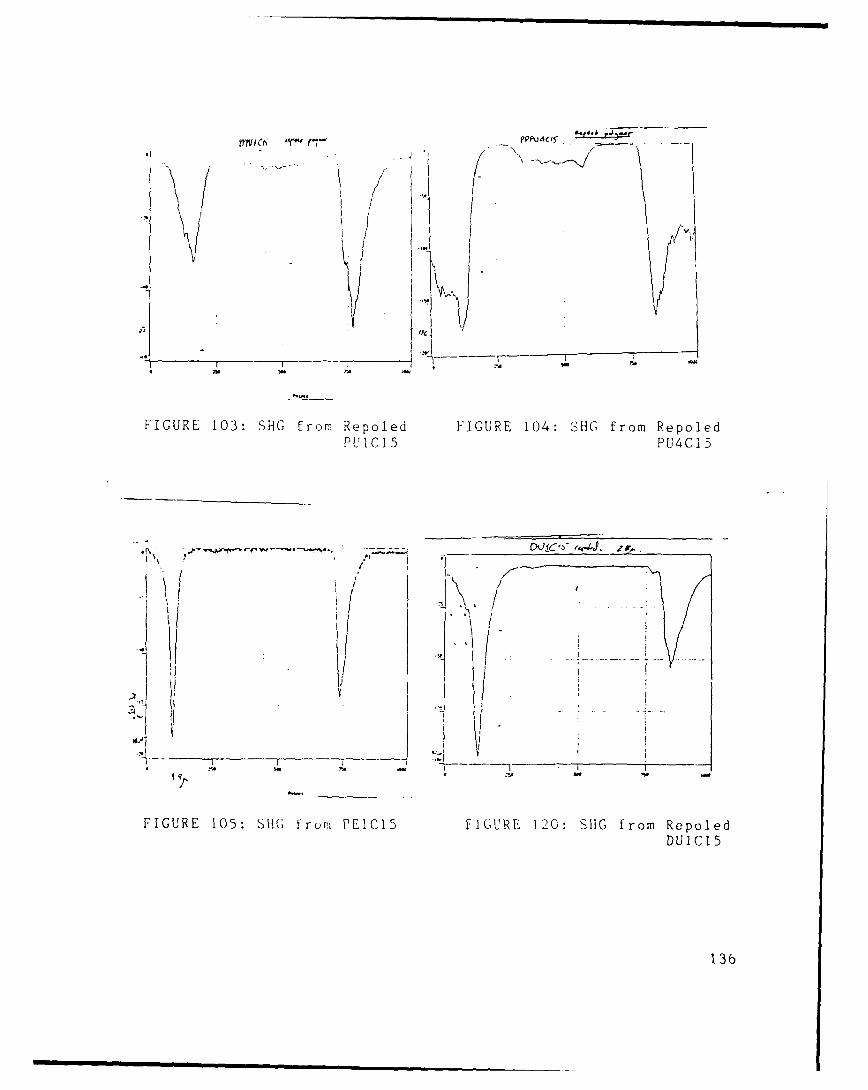
II. '1
a7-
/ I " , =
FIGURE 103: SHG from Repoled FIGURE 104: SHG from RepoledPUIC15 PU4CI5
//
FIGURE 105: SH1G from PEIC15 FIGURE 120: SHG from RepoledDUIC15
136

REFERENCES
1. Nonlinear Optical Properties of Organic and PolymericMaterials, ACS Symposium Series, Polymer ChemistryDivision, September 1982, Kansas City.
2. Molecular and Polymeric Optoelectronic Materials:Fundamentals and Applications, SPIE's 30thInternational Symposium on Optical and OptoelectronicApplied Sciences and Engineering, 21 - 22 August 1986,San Diego, CA.
3. Nonlinear Optical Properties of Organic Materials,SPIE's 32nd Annual International Technical Symposiumon Optical and Optoelectronic Applied Science andEngineering, 14 -19 August 1988, San Diego, CA.
4. A.F. Garito, K.D. Singer and C.C. Teng in Nonlinear OpticalProperties of Organic and Polymeric Materials, D.J.Williams, ed., ACS Symposium Series, PolymerChemistry Division, September 1982, Kansas City.
5. S.K. Kurtz and T.T. Perry, J. Appl. Phys., 39 (8), 379811968).
6. J.Jerphragnon and S.K. Kurtz, J. Appl. Phys.., 41 (4),1667 (1970).
7. E.E. Havinga and P. Van Pelt, Ber. Bundsenges. Phys.,Chem. 83, 816 (1979).
8. G.R. Meredith, J.G. Vandusen, and D.J. Williams inNonlinear Optical Properties of Organic and PolymericMaterials, D.J. Williams, ed., ACS Symposium Series,Polymer Chemistry Division, September1982, KansasCity.
9. D.J. Williams, Angew. Chem. Int. Ed. Engl. 23, 690(1984).
137
10. J.B. Stamatoff et al., in Molecular and PolymericOptoelectronic Materials: Fundamentals andAlolications, G. Khanarian, ed., Proceeding of the SPIE's30th International Symposium on Optical andOptoelectronic Applied Sciences and Engineering, 21 -
22 August 1986, San Diego, CA.
11. K.D. Singer, J.E. Sohn and S.J. Lalama, Appl. Phys. Lett.,49 (5), 248 (1986).
12. M. Eich et al., J. AppL Phys.., 66 L6)., 2259 (1989).
13. I. Gorodisher, Master's Thesis, MIT.
14. F. Zernike and J.E. Midwinter, Applied Nonlinear Optics,John Wiley & Sons; New York, 1973, p. 26.
15. R.J. Twieg and K. Jain in Nonlinear Optical Properties ofOrganic and Polymeric Materials, D.J. Williams, ed., ACSSymposium Series, Polymer Chemistry Division,September1982, Kansas City.
16. Reference 4, page 5.
17. Reference 15, pages 60, 61.
18. Reference 14, pages 3 and 29 - 31.
19. ibid, p. 43.
20. Buckley et al, Proceeding of the ACS Symposium onSolid State Polymerization, New York, April 13-18,1986.
21. A.Yariv and P. Yeh, Optical Waves in Crystals, Wiley,1984.
22. Reference 4, p. 7.
23. J.D. Swalen et al, IBM Research Report, Physics,September 27, 1989.
138

24. G.E. Wnek et al in A.J. Heeger, J. Orenstien and D.R.Ulrich eds., MRS Syposium Proceedings, 109,139,(Boston 1988).
25. H. Abdel-Halim et al., J. Phys. Chem., 90, 5654 (1986),
26. A. Mangini and R. Passerini, J. Chem. Soc., 4954 (1956).
27. A. Mangini and R. Passerini, J. Chem. Soc., 1168 (1952).
28. G. Modena, Proc. 4th Intern. Meeting Mol. Spectry.,Bologna, pp. 483- 490 (1952), Chem. Abstr. 59:4688h.
29. H.H. Szmant and J.J. McIntosh, J. Am. Chem. Soc., 73,4356 (1951).
30. A.E. Lutski, E.M. Obuhova, and R.C. Cheshko, Zhur. Fiz.Khim. 42(8), 1861, (1968).
31. V. Baliah and V.M. Kanagasabapathy, Indian Journal ofChemistry, 16B, 810 (1978).
32. L.M. Litvinenko and R.C. Cheshko, Zhur. Obshchei Khim.30, 3682, (1960); L.M. Litvinenko and R.C. Cheshko,Izvest. Vysshikh. Ucheb. Zavedenii, Khim. i Khim.Technol., 3(1) 99, (1960).
33. J.B. Hyne and J.W. Greidanus, Canadian Journal ofChemistry_47, 803, (1968).
34. R.M. Silverstein, G.C. Bassler, and T.C. Morrill,Spectrometric Identification of Organic Compounds, J.Wiley and Sons, N.Y. 1981, pp. 305 - 308.
35. Jerry March, Advanced Organic Chemistry, Wiley, NewYork, 1985, pp. 238 - 245.
36. S. Inoue et al., Synthetic Metals 28, p. D231, (1989).
139

37. A. Mangini, Pure Appl. Chem., p.103, (1963).
38. J.-L. Bredas, in Handbook of Conducting Polymers, editedby T. Skotheim (Dekker 1986), pp. 893-894.
39. C.B. Duke and A. Paton, in Conductive Polymers, editedby R.B. Seymour, (Plenum, 1981), pp. 162-165.
40. K. Ikawa, Yakugaku Zasshi, 79, 764 (1959); Chem.
Abstr. 54, 10922h (1960).
41. G.W. Raiziss et al., J. Am. Chem. Soc., 61, 2763, (1939).
42. R. Lantz, U.S. Patent # 1,965,776.
43. L.M. Litvinenko et al, Zhur. Obschei Khim., 29, 1470,(1959),Chem. Abstr. 54, 8721c, (1960).
44. L.M. Litvinenko and N. F. Levchenko, Zhur. Obschei Khim.,29, 3079, (1959).
45. Y.O. Gabel and F.L. Grinberg, J. Appl. Chem. USSR EnglishTransl.,.12, 1481 (1939); Chem. Abstr. 34, 6244(1940).
46. M.S. Zhedek, Zh. Prikl. Khim. 25, 109 (1953); Chem.
Abstr. 47, 867a , (1953).
47. Porter, Organic Reactions 20, pp.455 - 481, (1973).
48. Dr. Yen Wei, unpublished results.
49. Dr. G.E. Wnek, unpublished results.
50. Dr. G.E. Wnek, private communication.
51. H. Gilman and J.F. Nobis, J. Am. Chem. Soc., 71, 274,(1949).
52. A. Mangini and R. Passerini, Gazzetta Chim. Ital., 84,606, (1954).
140

53. D.J. Pasto and C.R. Johnson, Laboratory Text for OrganicChemistry. Prentice Hall. N.J., 1979, p.48.
54. G.B. Butler and F.L. Ingley, J. Am. Chem. Soc., 73, 895,(1951).
55. W.E. Gibbs and R.J. Van Deusen, Journal of PolymerScience, 54(159), S1, (1961).
56. G.B. Butler and R.J. Angelo, J. Am. Chem. Soc., 79, 3128,(1957).
57. G. Odian, Principles of Polymerization, Wiley-Interscience, N.Y. 1981, p. 239.
58. ibid, pp. 243 - 246.
59. Dr. H. Hall, private communication.
60. T. Sulzberg and R.J. Cotter, Macromolecules 1(6), 554(1968).
61. T. Sulzberg and R.J. Cotter, Macromolecules 2(2), 146
(1969).
62. Reference 86, pp. 103 - 105.
63. H.R. Allcock and F.W. Lampe, Contemporary PolymerChemistry, Prentice-Hall, N.J., 1981, pp. 29 - 31.
64. R.W. Lenz, Organic Chemistry of Synthetic HighPolymera, Wiley-lnterscience, N.Y. 1967, pp.86 - 88.
65. S.R. Sandier and W. Karo, Polymer Synthesis, pp. 66 - 67,and pp. 74 - 84, Academic Press, N.Y. 1974.
66. C.A. Bischoff and A. von Hedenstrom, Berichte derDeutschen Chemischen Gesellschaft 35(3), 3452(1902).
67. J.F. Wolfe, B.H. Loo, and F.E. Arnold, Macromolecules 14,915 (1981).
141

68. G.T. Morgan, Journal of the Chemical Society 81, 1382(19_02)... ..
69. P. Hartley and J.B. Cohen, Journal of the ChemicalSociety 85, 868 (1906).
70. E.H. Nason, J. Am. Chem. Soc. 40, 1602 (1918).
71. M.J.J. Blanksma, Recueil des Travaux Chimiques desPays-Bas, 21, 419.
72. G.S. Hammond and F.J. Modic, J. Am. Chem. Soc., 75,1385, (1953).
73. R.A. Wessling and R.G. Zimmerman, U.S. Patents #3,401,152 and 3,706,677.
74. J.D. Capistran et al., ACS Polymer Preprints 25(2), 282(1984).
75. Reference 86, p.108.
76. ibid., p.136, reference 93, p. 1 8 7 .
77. Reference 34, pp. 105 -128.
78. B.D. Cullity, Elements of X-ray Diffraction, Addison-Wesley, MA, 1978, p. 102.
79. D.K. Das-Gupta and K. Doughty, IEEE Transactions OnIndustry Applications 1A-14 (15), 448 (1978).
80. D. Kingery, K. Bowen and D. Uhlmann, Introduction to
Ceramic.a, p.947, Wiley-Interscience, N.Y. 1976.
81. Reference 64, p. 185
82. G.T. Boyd, Thin Solid Films 152, 295 (1987).
83. D.J. Williams, Angew. Chem. Int. Ed. Engl. 23, 690(1984).
142
84. Hampsch et al., Macromolecules 21, 526 (1988).
85. Marks et al., in Nonlinear Optical Properties of OrganicMaterials, G. Khanarian, ed., Proceeedings of SPIE's 32ndAnnual International Technical Symposium on Opticaland Optoelectronic Applied Science and Engineering, 14-19 August 1988, San Diego, CA.
86. References 10,11,12; also D.A. Ender et al. in NonlinearOptical Properties of Organic Materials. G. Khanarian,ed., Proceeedings of SPIE's 32nd Annual InternationalTechnical Symposium on Optical and OptoelectronicApplied Science and Engineering, 14 -19 August 1988,San Diego, CA.
87. G.R. Meredith, J.G. VanDusen, and D.J. Williams,Macromolecules 15, 1385, (1982).
88. Reference 43, p. 380.
89. Dr. Yen Wei, unpublished results.
90. David Pugh and John 0. Morley in Nonlinear OpticalProperties of Organic Molecules and Crystals, D.S.Chelma and J. Zyss. editors, Academic Press, Inc.,Orlando, Florida, 1987, p. 220.
143