Embed Size (px)
Citation preview

.
‘.,
i
.
#
i’
I
i
:&
,,d
It’
~pil
NATIONALADVISORYCOMMITTEEFOR AERONAUTICS
TECHNICAL NOTE 3737●
THE MOTIONS OF ROLLING SYMMETRICAL MISSILES
REFERRED TO A BODY-AXIS SYSTEM
By Robert L. Nelson
Langley Aeronautical Laboratory
‘L
Langley Field, Va.
t’. ‘. ‘......—-. ...
Washhgt.on
November 1956
.
.- .,. =,- .-
.-
-------- --->- ----- .. . .. , .-..#— -- ------ ...
https://ntrs.nasa.gov/search.jsp?R=19930084513 2018-06-09T22:29:56+00:00Z
lE
. .
: NA!rIoNALADVISORYccMMITJm
TBCHUBWY K&iNM
FoR AERONAUTICS IullllnunlmlllOULL32U
TECHNICAL NO!l!E3737
THE MOTIONS OF ROIUNG SYWETRICALMISSILES
REFERRD TO A BODY-MIS SYSTEM
By Robert L. Nelson
SUMMARY
The linearized eqyations of motion have been derived for a rollingmissile having slight aerodynamic asymmetries. Time histories of rolltng-missile motions referred to a body-axis system.have been prepared to showthe types of missile motions that can be encountered. The motionsresulting frm a trh change and a pulse-rocket disturbance are shown tobe determined mainly by the ratio of rolling velocity to pitching frequency.
l?inally,the derived equations are used in establishing a techniqpe forthe reduction of rolling-missile oscillation data. It is shown that theaerodynamic derivatives can be obtained fran flight dati if four accelera-
1 tions are measured. The method is applied to the relmlts”obtained from aflight test of a dssile configuration.
INTRODUCTIONI1
The problem of the dynsmic stabilitytwo separate basic treatments. First, in
of missilesthe case of
has been attackd byroll-stabilized mis-
1
siles the problem has been attacked by means of the classical airplane-II
stability theory developed by Manchester (ref. 1), with no need for motifi-cations. The development of the theory for rolling symmetrical missiles Ihas followed from the basic.ballistic theory of reference 2. Nicolaides(ref. 3) snd Charters (ref. 4) have more ~ecently expressed the dynamic-stability equations for rolling symmetrical missiles in terminology more Ifamiliar to the aerodynsmicist. However, the ~etus for these works wasprovided by studies of missile motions in aerodynamic test ranges where themodel position ~d angular orientations were measured at a series of sta-tions. As a result the equations derived were referred to space axes. Mthe case of free-flight rolling missiles eqyipped with ‘internalinstrumen-tation, the equations of motim mu@ be referred to a body-axis system.Phillips in reference 5 presented a simplified analysis of the motion ofrolling airplanes (and in a limiting case of symmetrical missiles) based ona body-axis system but included only the criteria for stabiti@. B-olzinreference 6 derived more completely the equations-of motion for a rolling
1.
------ .. ..- --- . ,---- . . —..—. .-. .— ---- .- —---- .- —.... -.—.-———————--- -- -----—

.
2 NACA TN 3737
symmetrical missile referred to a body-axis system but ag&n discussedonly the criteria for stability.
In this paper the equations of motion referenced to the body-axissystem are again derived, and assumptions similar to those of Nicolaides(ref. 3) are used. Some of the possible missile motions are shown,together with the motions to be expected from certain furcing functions.Finally, the derived equations of motion are used to establish a techni-que for the reduction of oscillation daka to obtain aerodynamic deriva-tives. The method is ap@_ied to the experimental results obtained froma rolling symmetrical missile.
a
A,B, C
AF
cm
sYMeoIs
resultant acceleration
complex roots of differential.equation for ~
accelerations parallel to X, Y, and” Z axes,respectively
constants of clifferential equation for ~ .
body frontal area, sq ft
%pitching-mament coefficient, —qAFd “
.
%,=7—,secaap .
CN normal-force coefficient (-CZ)
I
#“
.
.
.
..-_ -— ——— . . . .. ..——. .. ..

, NACA TN 3737
.,’ C* yawing-mment
&nCn =— “pap”
acc~ = + 8’=
acnc%= @&i’“C
a%c%” = a(l+),~
CR _t@e of resultant vector
%
,
.
,
3
coefficient, %qAFd
t
%,0
%-Cyp = ~
Cz
Cz,o
aczc&=_
ilk
d
Fx> Fy> FZ
I
lateral-force
lateral-force
vertical-force
vertical-force
body diameter,
Fycoefficient, —
qAF ●
coefficient due to asymmetry .
Fzcoefficient, —
qAF
coefficient due to asym&q
ft
aerodynamic forces “parallelto X, Y, and Z axes>respectively
moment of inertia about Y- or Z-axis, slug-ft2
. .
1’=1 -~ sec2“qAFd
.-. . . . . . . . . . . .. .. ____ _= ._ ... ..- ..- -. --— ------ —-—?——---------- —--—— -—...- .-_. ..—

4.
wA.~ 3737
Ix
i =r-1
mament of inertia about X-axis, slug-ft2
k radius of gyration}
z ptie-rocket moment
J!w % % aerodynamic moments
m mass, slug
m’=m —, secqAF.
nI m, ft
arm from center of gravity, ft
about X, Y, and Z axes, respectively
pulse-rocket total impulse, lb-see .
rollingvelocity, radians/see
mcpress~e, l.b/sqft
initial msguitude of rotating vectors
slope
the
ccmponent of free-stream velocity in X-direction,ft/sec (u-V)
free-stresm veloci@, ft/sec.
coordinate axes
longitudinal center of pressure of asymmetric force, ft
longitudinal displacement of accelerometers,ft
lateral displacement of accelerometers,ft
vertical displacement of accelerometers,ft
.
..
.
#
4
#
t
1,
.
. ...1
●
.
.
-. -——-.. ..- —.— ---- .—.

,
.
NACA TN 3737 “5
a angle of attax, radians
\
.
#
#
1
P angle of sideslip, radians
i pitching velocity, radians/see
A ~ orientation of resultant vector, radians
A. ncmrolling dsmping constant, l#&ac
AA -* cpIIStant dueto roll, l/see “
P relative@ensi-@ factor, 4mpAFd
VI>V2 initial ~ orientation of mutating vectors, radians
P air density, slugs/cu ft
4 rolling yelocity, radians/see
if yswing velocity, radisns/sec
~o basic oscillation frequency, radisns~sec
Al) ccmponent of total pitch frequency resulting directlyfrom roll, radians/see .
.Dots over symbols indica@ time derivatives.
.
,
STATWENTOF THE PROBLEM
The motion of a symmetrical missile configurationreferred to a body.axis system-iscomplicatedby rolling motion even for the case where therolling velocity is a fraction of the missile pitching frequency. Unlikethe motion of a slowly rolling airplane-~ configurationwhich ,ten@stocontinue in a direction normal to the wing plane, the motion of a symmetri-cal missile configuration disturbed in one plane ‘in space tends to remainin one plane in space. (The restoring force for the airpland is normal tothe plane of the wings, whereas the restoring force for the missile is
. . . . —.—.. .— ..- .__-. .- . . ..— . .. . . ___ -A --- --- --— ..-. - —. —L-.———.— ——— . . . . . . . _

6- NACA TN 3737
mainly independent of roll attitude.) Thus for a missile having acceler- , ~meters mounted at the center of gravity the first consequence of the .rolling motion is the appe~ance of a roll effect on the normal and $(
transverse accelerometer traces. An.exsmple of this effect for the normal- “accelerometer trace is shown in the following sketch: ,
.*
.
This roll effect is determined mainly by the ratio of the rollingvelocity to the oscillation freq~ncy, or the ratio of pd/2V to u@/2V. ‘ ‘
At very low values of pd/2V corresponding to very small fin misaline-ments, this ratio can become large if the missile ascends to a high alti- =tude, inasmuch as - pd/2V is independent of altitude while qd/2V
decreases with increasing altitude.
H the missile motion were in one plane in space and the roll ratesmall, the motion could be analyzed simply by working with the resultantof normal.and transverse acceleration, and applying the usual data- ireduction techniques for oscillating nonrolling models (ref. 7). However, “ ‘since the missile may not remain in one plane in space snd gyroscupiccross-coupling can have a large effect on the model motion, an anslysis
1“
of the motions of rolling missiles 5.snecess~ in order to interpretand reduce the fl&ght test data.
DEVELOPMENT
The linearized eauations
OF EQUATIONS OF MOTION
of motion for a symmetrical missile (90° :
rotational symetry) are referred to the body-axis system of the follti ng “sketch:
. .
.
— -— ----- —-..—. —.-..——— ——. .. —-—-- ————

.
.
mCA TN 3737
,’
.
.f .
-.
,
,
z
On the assnrption that angular deviatiou from trim are small butthat large rolling velocity must be considered, the equati- of motionreduce to
-.a
.
9
--- .. ..- ---- ---- --- .-— ....=.. --- -— ---- ._ -—.—- . - . . ———.. -

8
If the
/
1
forward velocity is ass-d to ~e constant
rolling veloci@following four:
Ih order to reduceare multiplied bytivel.y,to obtain
.
also to be constant (~ = O), the
the
i =
IItu(B+$-ifa)=xFy
mu(LL6+j3j3)=zFz
iJ-(l-Ix)jkj=q
f“+(I-Ix)@=~
l!WA TN 3737
(~ = O) and the
equations reduce to the .
(1) “
(2) “
(3) ‘
(4)
tier of equations to two, equations (2) and (4)@ and added to equations (1) and (3), respec-
.
IAC= fl+iu, Q= ~+i$, and$ = p so that time equations become:
●
.
() Ix X(MY + ~)h+ipl-y$l= I
(5)
I
.
1
(6)
Allowing small asymmetries (resultingfrom a fixed control deflection forexample) which do not violate t- assumption of symetry and assmning that ithe aerodynamic forces due to ~, Cl,and ~, and forces due to gravitysre negligible in comparison to the forces due to angle of attack and
.
.“
___ .—— ------— ———-— —-—— ——- -—-— .—. .-— .—. -

E“WA m 3737 9“
sideslip permits the force eqyations to be written as:#
EFZ = C4CAAP+ czo~AF
Then, multiplying the second equation by i and adding to the first gives
z(Fy+ m’z) (=qAF CYP~ + iC&) (a + qAF Cyo + iczo
).
llrom the assumption of symetry,
The derivative ~ rather than CyP or C% is used hereinafter, sfnce
the force due to appositive angle of attack is usually considered positive.Then,
.
Z (Fy -I-iFz) = -~#~(13 + i~) + qAF(~o + iCZo)
Let m’ = ~; then, inasmuch@F
%J Cyo + iczo= -— +
m! m’
.
.
.----- .---------------- ---- ... ___ .------- ____ .... -.-— .. ..-—— ----- .. --4-- .--— .- —.- ---- -—- *

,:.
10
If no momentseffects and if the
NACATN 3737
.
from asymmetries.are.allowed to result from caibermoments due to 0, $, and ~ are assumed to make a
‘).
I
significant contribution to the total moment, the mment equations canbe written as:
.,.
“,
J@in, multiplyingthe first gives
the
●
With the assumption of
..
‘. \#
second of these eqyations by i and adding it to ‘
900 “ro&tioti Synunetry,
,.
..
*
,
“.
.
#>:,
J .. .*—. .— -—”..-- — ----— —.-——-

8
.NACA TN 3737 I-1
. ..\
-\”
. .
..
.,
I
“.
.
.
,1 &.
ic%(d + i$) -1
(%. + iczo)?
. .
fiSO, with.
Z(l’ly+ iklz)
I
Ww.tiom (5), (6), (7), and (8) c~i~ to give two kb.ear differentid.equations in terms of the two unknowns ~ and Q. The following equa-
. tion in’ ~ results:
‘ where
.-(9)
. .
cNa ~A=
()
Ixiiil--~+iP2-y
(10)
~“’-” ,_e .4 ,...
u
B-k+ ic>p+p21- %+%%a-ip%-~-~%. 1’ () I I! ~i
(m’ I’ I m’)1A — \—_____,—
c =-l-lA
“1. .-.. (11)
.
..
,..’,
. . .. . . . .. .- —. ------- ... . -.—------. ----- --- - . . . .... . . . .. . . . . . . ---.---—— . .. . . .- ..—-- )

.
‘1.
I-2 NACA TN 3737,.
●
.
c = ~tti+ Rle‘V1 eat ‘V2 ebt+ %!=
The solution of the differential equation is:
. .
‘4
where:
r-A+ A +4Ba=2
.
b=-A- ~A2 + 4B
2
,.
4“,
.
#ivl iv2
I and Rle and we are initial conditions as shown in the adjacent . ,.
sketch. 1
i’
. .#
Both a and b are complex nunibers,with the ccmplex radical
A2 + 4B, and can be broken down into a more usable form to.
.“:...
i ,,.
7
I
I
L_ . .. —-—. —.. . .— ..— .—. —- . . . .
13
-.,
NACA TN 3737
.*~=
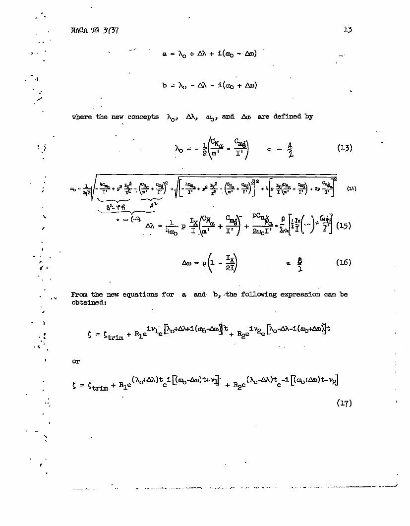
,,. ” . a=&+ AA+i(~-AO) “.
. -.1. #
.4 ‘
where the new concepts.
.
(13)
.?
expression can be
(16)
Mom the new eauations for a and b. the followiw. .. .,.obtained:
.,
I or
.
>.,
,I
.
..\
.,t
.
..—— --- . -...—. .+- ------- .—. .. . .. . . ------ J.. . .. . . .-. —-- ----- . —.. — — . . -—-

.
14 J!JACATN 3737 .
Inasmuch as a complex number represents a vector which can be expressed
in the form z=a+ib= Reie, whereR ‘epresenfi:s)-=: woffie&ctor and e gives the angular orientation, Rle
R2e(@)trepresent the dsmping with time of R1 and R2, respectively;
and (q - b)t+~ and (q+&jt-v2 give the location of the vet-
tors at any t-he. These”relationshipsare shown in the following sketch: “-
i(tx - Q&-h)A
i-a
Thus, the resulting motion is givenby two damping vectors revolving indifferent directions and at different rates about the fixed trim.
I
: . .
.
.
The time histories of CL and ~ csnbe obtained frcxnequation (17)
Wing the relations eie = cos e + i sin e and ~ = ~ + ia; then
(A&LSA)t~e rCos (~ +
{
~ ~ e(~+m)t sin ~%
1“ [
(Ao-m)tR2e
[ 1}sin (~ + Aw)t - V2 (18)
AfD)t + ~] +
1ti)t - V2 +
i-LuJt+v -
.
.\
1“,
,,
#
,.
/-
.
.—. — .— - . ....

“1.,8
I
a
I
● 1I
NACA TN 3737
and&+AA)t – —
[P- Ptih=Rle-” - COS (%- Z!fN)t+ q] +
= ~le@&AA)t
a - %rti [sin (~ -
1Cujt - v~
AD)t + Vq -
15
1&D)t - v~ (19)
or B ismadeupof twoThus the oscillation about trim of either usinusoidal componentswhich can have different initial magnit&s(R~#R~) andwhichcand amps .tdifferentrates (AX #O). When AA
approaches the value of ~, one of the component oscillations dsmps
rapidly while the other component damps slowly.
Rather than use equations (18 ) and (19) in the discussion whichfollows, use will be made of the resultant augle of attack from trim andthe angular orientation of this resultant. FYCUUequations (18) and (19)
‘ ‘(*)tRl e
2 2(&AX)t ++~e
( )2R1~e2bt cos 2~t + VI - V2 (20)
#wtANt[
(A(rAA)tCos (* - 2m)t + ~] + I&
[ 1Cos (~ + Al))t- v~
One interesting point should be made concerning equation (20). The rollrate p appears as an important qpantity only in the quantity Ah, whichis small compared with & at low roll rates. Thus, to the first order,a change in the rolling velocity will not influence the resultantoscillation time history, but will only influence the sn@lar orientation
.
1
#,
<’ ,..— .. .. .. .— - ---- .------------- ,.. .-. —. . ...- . . ... .. .....-— . -. —--— “.- .-—.. . . . . . . . . . . . . . .

16 NACA TN 3737
. .
of the resultant. Therefore, the assumption that the rolling velocity isconstant may not be too strict a limitation on the validity of the
,*.
-is at low roll rates.
The sectioqs which folluw discuss the motions of rolling missiles \
referred to the body-axis system and a technique for reduction of data of *missiles employing body-axis ~trwnen tation. In this system forcesmeasured at the center of gravi~ more conveniently describe the motionthan would the angle of attack, which cannot be measured at the center ofgrawity and must be corrected to the center of gravity.
l?rm the assumption made earlier that aerodynamic forces due to 6, -\
$, and @ ae negli@ble, the equations describing the force time his-tories ~ffeq from derived equations only by a constant. If the forcesdue to t3, v, and @ are not negligible, the new equations describingthe force time histories differ from equation (17) by the initial condi-tions RI, ~, Vl, qnd v2.
.
In theequations and figures to follow, use is made of the synibols ,as defined in the following table, for either angle-of-atta-blcand side-slip instrumentationor for force-measuring instrumentation. The coeffi- .ci~t CZ, which is positive downw=d, has been replaced by +. ‘
Epmbol I a and p system I ~ and ~ Syatam
% (9- 13&JJ2+ (CL- *)2 /(%-%,fJ.YiJn)2+“(%- %,mn)’
%- &=== &Y,t5=bn-‘d’+ (%,trim- %,0)2
A ~-la-%rim *-1 % - %,trim3t-
$-P- % - cY,trlm
f%’im~-l %,trim- %,0 -
Yc - %,trim- %,0
.
.
..
.
.
..— — . ...——. . .—..-—
.
IE,1 NACA TN 3737 17
DISCUSSI~ OF THE DERIVED MOTION
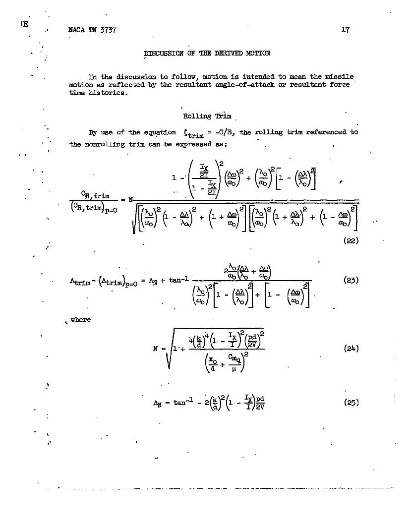
In the discussion to fofiow, motion is intended to mean the missilemotion as reflected by the resultant angle-of-attack or resultant force ‘time histories.
.
i
Rolling Trim,
-C/B, the rolling trim to/ .
By use of the eqy@ion ~tti =
the nonrolling trim can be expressed
referenced
..
\“ as:.
()Ix 2
1 -“()
_zL 4S2Ix %
1.. -m()%2
‘G,
.
.
~ “*.. . .
(22),.
.
%rim”- @trim)p~
,
(23)
.
.+ 1$)71-*)W()XO+ %2d~
(24)
.-
(25),,
.\ .
“t,’
4
. . ----- - ... —.-. ... . ..—. --- . .— .- --- ----- .---— - .---—-.——-—- ---- -— - --—--—----—-

18 NACA TN 3737
The quantities N and ~ are independent of the stability roots ~,
AX, ~, and Lm. ‘Inaddition, N and ~ are’independent of velocity:
and independent of lkch nwiber (if pd/2Vj ~, and ~/d are constant),
and N is influenced slightly by altitude &a&es (through the~u term).
Same examples of rolling-trimmagnitude and orientation are given infigures 1 and 2 for a partied.ar missile configuration. The assumedaerodynamic and mass characteristicsHsted in the figures are representa-tive of a four-fin missile of high fineness ratio. The resonant conditionat &/~ = tl iS shown in figure 1. An indication of the magnitude of
the rolling - at resonance for low values of dsmping is also shown.~s~ds~s” tmt the - rotates *o@ 180° as the resonance range
.
,,
0.
●
.
‘s
In order to give a better idea of the importance of the resonance range .and the associated problem of avoiding resonance, the equations for ~/~ .and &/~ are first written as follows:
o
(26) ‘
.-
,
(’7)
.
. .,,
.
-“
—.. — —.

.
NACA TN 3737 19
Note that both eqpations (26) and (27) are functions of only the masscharacteristicsof the missile, the aerodynamic characteristics,and thealtitude (through the relative density factor) and are independent of. velocity, except indirectly through the effects of Mach nmiber andReynolds ntier on the aerodynamic derivatives.
.
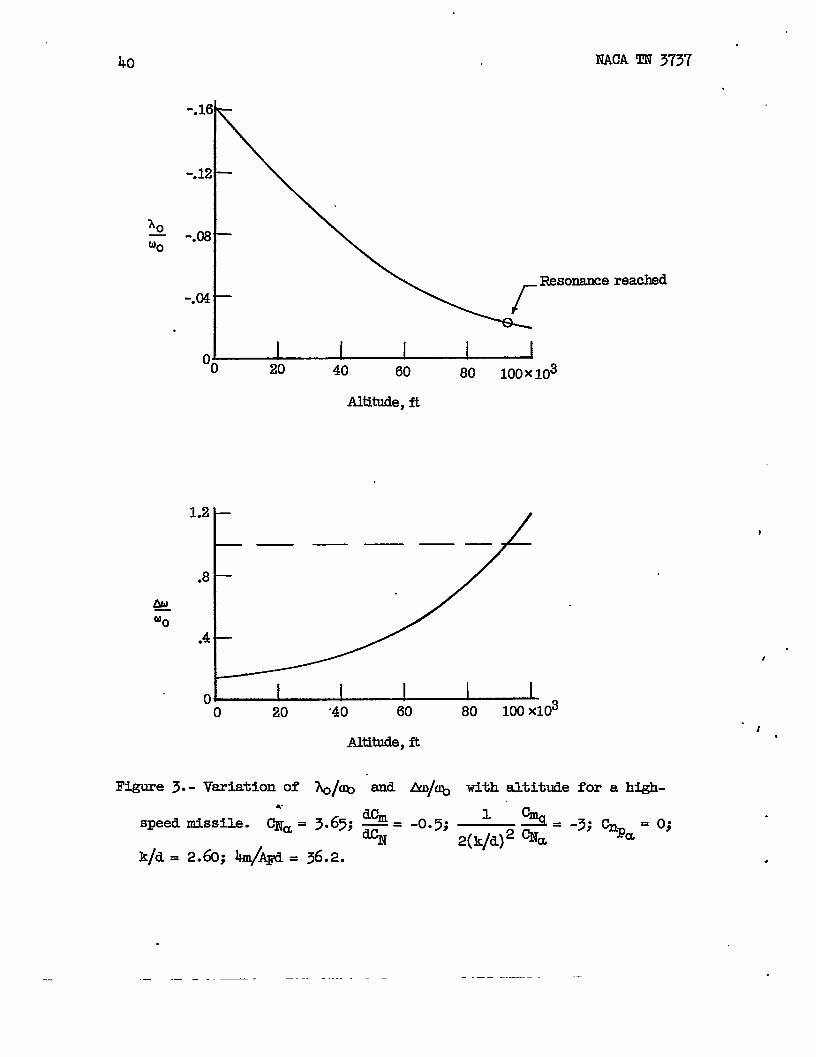
Figure 3 shows the variation of &/~ and &D/~ with altitude
for a high-speed missile. The asymmetries causing the roll were accid-ental and probably on the order of what can be expected Wth qualityconstruction of a finned missile. The curves show resonance reached atan altitude of 93, ~ feet and at X@ = -0.022. passing through
resonance at such a high altitude may be objectionable;for, even thoughthe resultant force may be less than at a lower altitudey the greatlyincreased trim angle of attack may be such as to put the missile in anunstable angle-of-attack range, which could lead to destruction of themissile or at least to a significant change in flight path. In addition,if the flight path is such that resonance occurs near zenith, then theresonance range will be passed through slowly and large changes in flightpath can occur. It may be that, for certain applications, the fins shouldbe deflected, so that resonance occurs at a predetermined low altitude.Although the motion about trim is not greatly affected by changes inrolling velocity at low roll rates, this result does not hold true forthe trim if changes in rolling velocity take place near roll resonance.
-. Mo*im About Trim#
Setting zero time at an,oscillation peak (V1 = V2) and replacing in,
equations (20) and (21) the initial conditions Rl, ~, Vl, and V2 by
the following:;,....
CR,O =R1+~“.
t
●
#
b%
. yield the f~llowing simplified equations:-.
}.“●
,(
.. . . . .-. ..- —- —_ .. . . .. ..— -. . . . . . .. .. .. ~_. - ....-_ -. -- -.— .—. .- ..---— _1

20 NACA TN 3737 ‘
A
A betterobtained
.
.~.~+~-l(l+K)#t-(l-K)e*t tan q)t (29)(1 + K)@t + (1 - K)eat
insight intothephysical significance of the quantity K isfrom the equation for dA/dt:
a . %~1+K)2e~t -(1 - K)2e-*t] + 2(1 - K?)& sin at
-ADat (1 + K)2ent + (1 - K)2e-Wt + 2(1 - K?)cos ~t
. (30)
At t=O
( )-
~~t=o= @-&l (31)
!I!he value of K is thus related to dA/dt at t = O. Now the motion ‘ “about ~ referred to an @s system in space, which translates, pitches,and yawa with the body-axis system but does not roll, is related to themotion with respect to a body-axis system by the following equations:
.
L*Jspace= (a)bo~axes ~ ~ -
%pace = ~ody
since the body-axis system rotates atin space is determined by the initialt o.= Also>
~es + Pt
the roll rate p. Thus, the motionconditions & and dA/dt at
()%pace IX
at ~.~++py
IxFor values Of ~Py that are small
K()
1 %pace=——% at t=o
,
.t
.-. ..— —- ——- ——— ——— ..— .—

21
.
.
.
.
t-
.
v-9
..
.
NACA TN 3737
Also, for the condition of zero roll rate (p = O),
!mus, fromthis, the motion
=*(=)$3=*(=)%o
2) +
frmn trim in space is nearly independent ofthe roll rate at low roll rates and low ~ues of I@; Since the
motion in space is determined mainly by the value of K, the quantity Kis called the “space-motionfactor”.
Figures 4 *d ~ present some Qpical motions about trim (~ against
A with time varied) given by equations (28)and (29)forvqriablevaluesof K and Am/~ and for zero damping (~ and AX = O). The effect of
~ on the patterns is ma@ to reduce succeeding peaks. The effect of
& is discussed in a stisequent section. The nuniberof cycles to cqn-plete the pattern are also shown.
.Some of the important characteristics of the motions shown in fig-
ures 4 and 5 sre as follows:
(1) For Ax/M = O, or for the nmtion in space, the pattern is
elliptical, varying from a line (motion in one plane) for K = O to acircle for K = *1 ●
(2) Whether K is positive or negative can be easily detected,for CR circles the trti center for negative values of K, but does notfor positive values of K.
(3) An indication of the approach of resonance is shown by thetendency for the loops to close on each other and become coincident fora given value of K.
(h) Whether the missile is above or below roll.resonance is imme-diately determined, since the motion above reso-ce is characterizedbyinside loops, and the motion bel-m roll resonance by outside loops.
(!5) ~orderto determine the value of thero~trimfra a plotof CN against Cy, a low value of K is desirable.
w indicated, a plot of CN against Cy (or CR ~~t A) tiu
yield imnediatel.yvaluable information about the motion.
.
. ....— --- .. -—.- . ---- —.. . .. .. . .— . -. —. .—— —-— — — .. . ..-. —— .— .— --—--—

22 NACA TN 3737
Ro13hg influences the dsmped motion through the term AX. FYomequation (28) the envelopes of @ are:
~,~ _ ebt[ 1~ (1 + K)emt + (1 - K)e4
CR,O
%,min ebt
%,0 [ 7= ~ (1 + K)e*t - (1 - K)eA
(32)
(33)
Typical oscillation envelopes of ~ below divergence (AA< ~) are
shown in figure 6. The figure shows that the effect of an increase in AAtends to - & oSCilktiOn of CR mOre ~~, eXCept for poSitive
values of K. For positive values of K the oscillation becomes less-d ‘ifi ~ tirease h ~/&, W to the t- where CR,~n = 0. ~t
with further increases in time, the oscillation becmes highly damped.Whether AA/& is positive or negative can be obtained from the following
equation for A?@:
For conventionalmissile configurations ~ ~ is negative and .
()2$2
.
of greater magnitude than ~a; as a result fSA~ usually bas the ssme
sign as &D/q.
1lx
Since the limiting magnitude of &o/~ is - m“ ~~IY
w can be between +J, AA~ will &ver exceed *1, if
CNa - +%
(),
.
-..——. —— —. —.. -—. .- ——. -—-. ——— . .-—. -.—- —— .—-- .————

.
.
.
.
NACA TN 3737
%~ is negative. However, a
instabili~ at hkgh roll rates
23
positive value of%&
can lead to
or high altitudes, or both. However, theinstability resulting from a positive ~% will be serious onJy if it
occurs at altitudes where significant dynamic pressure exists, since therate of divergence is negligible at extremely high altitudes. Thus,knowledge of the value of ~ is most impm%ant for missiles which
rolJ rapidly.
.Another way of visualizing the effect of Ah on the motion is
obtained by finding the variation of K frcm peak to peak of theoscillations or effectively setting the initial conditions and zerotime at succeeding peaks. Then, fr& equations (w) and (31),
Kt = (1 + K)@t - (1 - K)e*t
(1 + K)@t + (1 - K)e~t
Since
causesFigure
the motion to tend toward that given by K = *1 in figure 5.6 is in agreement with this concept. of course, at low roll rates
this trend is completely obscured since the oscillation is, for all prac-tical purposes, damped out by the time the influence of AX is felt.
been(and
RESPONSE OF ROLLING MISSILES TO FORCING FUN(HXONS
Thus far, motions resulting from variable initial conditions haved$scussed. Remaining to be determined are the initial.conditionsas a result the motions) that can be expected from given disturbances.
Response to a Trim Change
Assume that, at the time of the instantaneous control deflection, themissile was athad completelysystem at a -
I& initial trim and thedamped out. The initial~~~ P - Btrti about
oscillation about this initi~ trim .conditions are”referred to an axiswhich the oscillation takes place,
. .-. ..— .- ... . —--- . —-— ---— —-— —- -—— -- . - ----—- -— -- .-. — —-———— ‘—-

24 NA,CATN 3737
as indicated on the fol.lowingsketch:
These conditions sre expressed byJ
where
‘R,trim = /(%,tXim)2‘(%,t~ - %,trim(%,-)o Cos %r&
= tan-l (%jt*)O ‘in %iUl,O - %,trim‘in ~r~(%,tiilIl)O Cos %?jJn,O - %,t* Cos %r~
fhibstitutingthese initialfollowing &lues for Rl,
conditions into egyation (17) gives the
%, and V2 - Vl:
.
# .—--- —. .. ..- —. ___ _________ .- ______ .. ___ _.______ ___

25
.
% .I/(q - L!U3)2+ (~ + AA)2‘R,trim 2~i
Neglecting AA gives as the ~ vd~ of CR, fr~ eq~tion (2O),
at the time W, which is given by
V2*=
- VI
*
quantities
&=o
cR,max = ‘R,trim
compared with ~ and h.
.—-. —. ..- —— -—.. —.— ——— —

26
The value for K is
Then, for Am< ~
R1-~K=
RI + R2
K=&@o ‘
‘=*These results are plotted in figure 7. It
WA TN 3737
should not be inferred froqfive 7 that the value of ~,- increases with an increase in Am/~
above @m/~ . 1, since ~,- is referenced to Z!CR,~, which drops
off rapidly with an increase in Am/~ above &/~ = lZ as is shown in
figure 1. Note that, since the space-motion factor K and &/~ are of
the same sign, only the motion patterns for positive values of K in fig-ures 4 and 5 exe.possible.
Response to Pulse-Rocket Distm$bahce ,
A free-flight missile can be ,convenientlydisturbed from its equi-librium conditions by firing a small rocket charge mounted normal.to thelongitudinal.axts snd forward or rearward of the center of gravity. Sucha rocket charge is referred to as a ‘%ulse rocket.” For this simplifiedanalysis the rocket thrust is assumed to be constant. However the pulse-rocket total impulse (are’aunder the curve of thrust plotted sgainst time)and the pulse-rocket burning time, rather than pulse-rocket thrust, areused as variables. By use of methods sidlar to those used in the section“Development of Equations of Motion”, solutions have been obtained for thepe~ value of CR and the value of K at the peak, for cases where the
peak CR occurs before rocket burnout and after rocket burnout. The .
..

.
.
.
NACA TN
resultsdamping
3737 ●u27
arepresentedin figures8 and9 forthespecialmse of zero(~=o, AA= o).
Figure 8 shows the large effect the roll rate can have on the peakvalue of ~, where ~ is indicative of the resultant angle of attack.Figure 9 shows that the space-motion factor K rapidly approaches 1 ata given pulse-rockt burning time, as Am/~ increases in magnitude.
Both figures show the desirability of a very low pulse-rocket burningtime, first in order to obtain a high peak ~ occurring after pulse-.
rocket burnout, and second in order to restrict the motion to nearlyone plane in space.
APPLICATIONOFEQUATIONS OFMOTICX’JTOEST.ABLISHMENT OFA.
TECBNIQUE FORREDUCTIONOF OSCIILATIONIMTA
The procedure used in applying the equations of motion for the purposeof reducing the oscillation data is presented in two parts. The first partdeals with the determination of the stability roots, ~, ti, ~, and
A, and the second part deals with a method for obtaining the static and
-c *ro_c derivatives from the stability roots. It is sh~ thatthe derivatives c- be found by measuring four quantities in addition toairspeed and atmospheric conditions. Of course.,the accuracy of the deriv-atives obtained depends, to a large extent, on how well the assumptionsset down in the previous analysis are satisfied.
Determination of Stability Roots
Consider a rolling missile employing instrumentation at the centerof gravity for measuring the normal-force and side-force coefficients.If the missile is disturbed in such a manner that the space-motion fac-tor K is near zero and is out of the region of roll resonance so thatthe trim does not wander in magnitude and direction, plots of ~ against
Cy (or CR .~ainst A) simil,arto those shown in figure 4 and 5 can beobtained. A typical e~erimental plot is shown in figure 10. With thelowvalues of K,
The quantity
adjacent peaks on
a fairly reliable trim center can be assumed.
@m/~ is readily found by measuring the angle between
the plot of ~ against ~. (See following sketch.)
.—.— ___ . ..— ——- --— --

28.
NACA ‘IN3737
tq % - %T,trim
% - %,trim
This sketch can be used in conjun&tionwith
fk=Ao -@l
equation (29) to obtain
+Yt
t~) + 3t .
and since t2 and tl are measured at adjacent oscillation peaks
t@ l=&
and
&D_~ %-Al-—% If . (35)
. Calculation of @m/~ for all adjacent oscillation peaks gives an indica-
tion of the validity of the assumption that the roll rate p is constant.Also the accuracy of the calculated Am is affected by the correctness of .
.
...— . —.. - ——

.
NACA TN 3737
the assumed trim. The following table presents2m/~ for the experhental plot of figure 10:
29
the calculated vlihleSof
..
Peaks Am/*
lto2 o.~1
2t03 .325
3t04 .282
4t05 .308
The small variation of M/~ upholds the assumption
stant roll rate.
With the trim center known, the time history of
of a nearly con-
CR2 can be obtained
fr~ theplotof cN S&&Mt cy. D? sufficient oscillations are present,
the damping envelopes about the oscillation peaks can be drawn with goodaccuracy. Equations (32) and (33) represent the time histories of thedamping envelopes. Ifcan be written as:
%2= ~ ~R,max}2 +
use is && of--HE -“ing en%lopes, equation (28)
(CR,minfl + CR,$(l - K2)e2kt cos at (36)
2 is a sinusoidal damped oscillation about a~~ fr~ t~s equation, CR
trim given by*[~)~)2’ (cR@JT
IYmn the period of oscillation ~
can be obtained.
~ log2
.
From equations (32) and (33) and the damping envelopes,
~R,mx)2 - (cR,minfl = kt + Constant (37)
(& log %,IUX+ CR,min2 cR,max - cR,min)
= at + constant (38)
... —-.-—- . . ..— ..—- .. ——— — —--—

30 NACA!CN3737
Figure 11 is a plot of CR2 obtained from figure 10. Except near
the end of the oscillation,where an error in the assumed trim would havea large effect on time for-theoscillation peaks appear quiteis used,
%=
oscillation peak, the periods measured atgood. E an average period of 0.280 second “
— = 1.1.200.:80
Two special.correctionswere also used in evaluating the dsmping A..
First, since the assumed trim msy not be correct, the error would appear
88 an oscillation in*~!,-)2-+ ~R,minfi=
As a result, the periods
masured at points where the oscillation cuts ~&R,-)2 ‘(!,~.fiwould be inconsistent and differ from the periods measured at the peaks.An indication of the trim error is given by this inconsistency of the
period. As a result an adjusted value of*uR>~Y ‘~R,fifi has
been determined for each half cycle, such that the period is consistentwith the a$jacent peak periods. These adjustments to
*K!,-) + (%~)!l
.
sre indicated by the dashed Hnes. While this
correction is admitte&ly crude, it will provide a more nearly correct .damping curve.
The second correction is in consequence of the high speed and theflight path of this particular model. As a result, the air-densitychange during this plotted oscillationwas significant. On the assumptionthat the change in air density does not force the model oscillation, thedsmping at any time during the oscillation (if the veloci@ change isassumed negligible) can be written as
()k),t = A3,t=o &=
Then from equation (37)
~ )2 - (cR,min)~ = ~,~~(~).~ log CR,-
-- ..—. .— .

#
.
.
NACA TN 3737 31
Thus, this correction appears as a the adjustment. Figure 12 presentsthe damping determined, including the effects of each correction. Fromthe slope of the lower plot in figure 12,
~ = -0.736
Because of the low roll.rate, AA is small and cannot be obtained from
figure 11, since (%,*)’ = c).
Determination of Aerodynamic Ikrivatives
lh’om Stability Roots
First, equations ue written for the differential accelerations at. two points on the missile as measured by normal and transverse
accelerometers:
% = %(% Y2JZ2) - az(xl,Yl,zi)
(Y2 - Y1)F
These equations were derived under the ssme assumptions that were made inthe section “Developmentof Equations of Motion”. Stice MN = ‘tiZ/qAF
Lul day= m&iy/qAF,
----- .. . .. ..— . ..— ..-— — ——.”——— ——-— — . -.——— ——— --

NACA TN 3737
.
.
32
andmd(~ - xl)
%= ~[1
%
1
●lX.+l’@ye -
m(y2 - YI)@2
qAFd qAF
By use of equations (1) and (2),
If, then,
%=%a”+%vo>
f-y = %a$ + CY,o
% - %,oa=
%a
(Cy - CY,0)P =-
cNa
and
&_%l%=
.
b=-:a
.
. — -. —
5ENACATN 3737 , 33
Then,.
.
,-
.
pd
[
cnPa ~——- ~ CNa CNa
+
(39)
‘1 %+c%l 2 ~@2k2~%+( )[
1’2Acy. —_ —__ —-—
()
~2d ( )() ]d CNa P ~a 2V zd
Calstant +#K%)[z$+@~+2+ a
2 Ix
() )
2 IX dNdz:
() ]}&N +&y: —-—
CNa 1 2V(40)
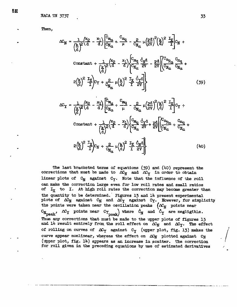
T& last bracketed termscorrections that must be made
linear plots of ~ against
can make the correction large
of equations (39) and (40) represent thetO MN and Ny in order to obtain
Cy. Note that the influence of the roll
even for low roll rates and small ratiosof IX to I. At high roll rates the correction may become greater than
the quantity to be determhed.” Figures 13 and 14 present experimentalplOts Of ACN sgainst CN and ACy against Cy. However, for simplicitythe points were tsken near the oscillation peaks (~ points neax
CN Acy points near Cypeak’ )
Where ~ and ‘~y are negligible.peak
Thus any corrections that must be made to the upper plots of figures 13and 14 result entirely froq the rOll effeCt on MN and My. The effect
of rolling on curves of ACy against Cy (upper plot, fig. 13) makes the!
curve appear nonlinear, whereas the effect on ~ plotted %*t ~ ,
(@per Plot, fig. 14) appears as an increase in scatter. The correction /for roll given in the preceding equations by use of estimated derivatives ,$
.
—.— .—. . __ __ .— —— .- .—

% NACA TN 3737
reduces the scatter and removes the nonlinesrities, as shown in the lowerplots of figures 13 and 14. The differences of 10 percent in slopes asobtained in the ~ and Cy planes is not understood. The effect msybe reai, resulting from different aeroelastic effects on the fins of the
. model, or be within the accuracy of the data.
Ths slope s of the curve of MN plottsd against ~ and ACy
against ~ is related to ~, Am, ~, and AA by the equation:
mu,
+7+-+AF +
For the test IEod.el,the necessary constants sre:
p = 76,600
~ = 8,1.20
Al? (42)
k = 2060d
Ix~ = 0.027
—..
.
.

NACA TN 3737
.
35
*
Then using the average of slopes from figures 13 snd 14 gives
CNa’= 0.0344 (~5.5 + 0.54 + O.*) = 4.35
Fran equation (13)
% = 2($)’&%+c%)Then
-1
.
+ 4.35) =“ -1..29
.
Equation (41) can
~ = 13.5~(:::)(-0.736) + 4.351
~= 13.5(-13.90
te rewritten as:
~= -’(m)’
Then
u.$+1#-&
.
(43)
c%= -0.0156 (125.5 + O.% - 0.0023) - 0.w732
= -1.~- o.~ = -1.977
.. -—.. -— —.-. — -——-.—— . ——. --. —

36
and
NACATN 3737
%% 1.977—= —=. — =~N CNa k.35
With ~ snd%
lnlown, the derivativea
equation (~) and is given by:
-0.455
C%acan be obtained from
(45)
AAthe
Avslueof ~ for the test model could not be determined, sincePa
could not be determined with any accuracy at the low roll rates oftest.
It should be emphasized that the biggest drawback in obtaining goodaccuracy is in failure to determLne the trim center correctly. In orderto obtain a reliable trim center, the missile should be disturbed in suchmanner that K is small in magnitude, and the resonance range should beavoided.
CONCLUDING REMARIW
~ analysis has been made of the motions of rolling missiles havingslight aerodynamic asymmetries. The motions were referred to a body axissystem. ‘Ihetype of motion encountered by the missile is shown to bedependent on the ratio of the rolling velocity to pitching freqpency andthe manner in which the missile is disturbed. The equations of motion werefound to be useful in establishing a techniqye for the reduction of oscil-lation data for rolling missiles having body-axis instrumentation. Themeth’6dwas applied to experimental results obtd.ned from flight tests ofa rolling missile configuration.
Langley Aeronautical Ikboratory,National Advisory Committee for Aeronautics.
Langley Meld, Va.,my 1, 1956..
.
-.— .

NACA TN 3737 37
REFERENCES
1. Jones, B. Melvin: Ilvnanicsof the Aer@-ane. Vol. V of Aero@nsmicT@&’y, div.pp. 1-222.
2. Fowler,R. H.,Aerodynmksser.A, ml.
Nj W.~. ~tid, ed., Julius Springer (Berlin), i935,
Gallop, E. G., Lock, C. N. H., and Richmond, H. W.: Theof a Spinning Shell. Phil. Trans. Roy. Soc. (London),221,1920,Pp..295-%7.
3. Nicolaides, John D.: On The Free Flight MotionSlight Configurational Asymmetries. Rep. No.Labs., Aberdeeh Proving Ground, June 1953.
of Missiles Having8.38, Ballistic Res.
, 4. Charters, A. C.: The Linearized Equations of Motions Underlying theXC Stabiuty of &cr@, SPi- Projectiles, and SymmetricalMissiles. NACA TN 3350, 1955.
5. PhilliPs, William H.: Effect of Steady Rolling on Longitudinal andDirectional Stability. NACA TN 1627, 19k8.
6. Bob, Ray E.: Dynsmic Stabilityof a Missilein Rolling l?light.Jour.Aero. Sci., vol. 19, no. 6, June 1952, pp. 395-403.
7. Mitchsm, Grady L., Stevens, Joseph E., and Nomis, Harry P.: Aerody-namic characteristics and Fl@ng Qualities of a Tailless !Eriangular-Wing Airplane Configuration As Obtained From Flights of Rocket-Propelled Models at Transonic and Low Supersonic Speeds. NACARM L&lLo7,1950.
.
. .
.
—. - .--. — —— .— —.. — _ _ .- -.——

16
14
12
10
8
61
1.
A
,-LNa
L60
$?40g32(Ju
00 -.04-.06-.12-.16-.20
?@o
4 —
2 —
n. I I I I I I I I I 1“.
o .2 ,4 .6 .8 1.0 1.2 1.4 1,6 1.8 2.0
AfyMo
sFigure 1.- Examples of rolling trim magnitude for a particular missile configuration. !l!he quan-
4_~ -3; ~= (),j
2 = o.()~; ~(k,d)2 ~ =tiw N is defined by eqw.tian (24). ~
,,,
.

. ..-
r r . 4
.
f
1
I
,
1
i
\
I
-180L_ “
0-.05-.10-*15-.20
.I I I I I
1.2 1.4 1.6 108 2,0
.-
5l?Lgure 2.- Angulex orientation of rollLng trim for a particulex missile. ~ = O. 0392;
1 ~= -3; c~m = o. LIheangle AN .Is defined by equation (25). (For negative
2(k/d)2 mavalues of &/u, the el~ of ~~ Le reversed. )
. .
40 NACA TN 3737 “
.
-.16
-.12—
-.08—
Resonancereached-.04”—
,o~20 40 60 80 100X103
Altitude,ft
1.2
r
——
.8
m—MO
.4
——
80“o 20 “40 60
Altitude,ft.
Figure 3.- Variation of ~/~ end A#%
sPeed ~ssfle” ;a = 3“65; ~ = -0.5;
k/d = 2.60; kmlA@ = 36.2.
— .— — . . . . .
8
“)
with altitude for a high-
1 !3 = -3; ~pa = o;2(k/d)2 %
.
-.——

Typical missile motions below rollresomdce for AD/%” pos-
For negative values of Aq/%, the sign of K is reversed.= o.
3EIUlcll m 3737
.
#
.
.
.
.
,
41
-wooo”oo@A.&.o . .2s m 3s Loo
Cyc3Myck
Jmtklm,2 4 8 I
....— __ ._.—..—_ _____ . ..-— .-—— --- . .—.. .

I
I
‘“’+000000‘+”QOQO Q“+)@@ ~ @
-’@ (3 c1
-6??9000000AduodO 1.5 20 2.5 3.0 3.5 4D
Cyc!+alaOompletnm-I 4 2 4 I 4 2
l?iwre 5.- !lhical missile mtione above roll resonance for LaJw poOl.-
“tive. For negative values of A#%, the sign of K is reversed.
~=m=o.
.

.
a
,- ..
r
.
I
10I
L—%Tm
1, —-——CR ~“
.5.
i:) o
I Lo
i .3L_‘\-. ---
oLo
.3
Lo -1 -2 -3
(a) f = 0.
L_K=lll
L
K= 0.3
\\\ .— -
L
K=O
,. —---
k
L&k0 -1 -2 -3 -o -1 -2 a -4
A. t
(b) ~ = 0.25. (c) $= O.m.
I.+-l&&l+_I_&+o 0
(d) ~= 0.75. (e) $= 1.00.
I Figure 6.- Envelopes of the ~ osciL1.&tionsfor AA/& positive. For negative values
Iof &~, the sign of K is reversed.
I
I

NACA TN 3737
3 — o-.05-.10-.
2— -.48
CR, msxACR, ~
~ .
F .
0 I I I 4 1,1,1111,11,,,,1,,,,1, ,,,10 .5 1.0 1.5 2.0 2.5 S.o
fM#wQ
Lo—
.8 —
.6 —
K
.4 —
.2 —
o 11111111, ,11,1,1,,,,1,, ,,1
A&/w.
Figure 7.- Response of a rolling symmetrical missile to a trti change. .
.
———.. . _____ -—— . —— . —. __ ____ ______ . _ _ _ _ -_ -_

NACA TN 3737
1.(
bCR
.4
.2
co
-l?eakafterburnout
.2 .4 .6 .8 1.0
‘o~ x Pulse-rocket burning time
~gure 8.- Amp~tuite response of a ro~ symmetric~ missile to tiedisturbance from a pulse rocket having constant thrust. ~ = O; LA = O;
. —...—— —. __ _. _. — --- —— .-— —

46 NACA TN 3737
% *-~ket buln3ng -TX
Figure 9.- Effect of pulse-rocbt disturbance on the
a s=trical missile.(
~=O~A4=0. Kand
sign.)
00
a
motion in space of
Am~ have the same .
.
. —. ——_____ .__. ._ .-

NACA TN 3737
.
.
.16
.14
.12
.lC
.m
CN
.Oe
“ .M
.02
0
-.02
-.04
-. -.04 -.02
Assumed trimcenter
I I I I I I !.02 .04 .06 .06 .10 .12 .14
CY
Figure 10.- Plot of ~ against C!y for a rolling
a pulse-rocket disturbance.
missile following
. .
..-. —... —. .—.—— —— —-——— .-.-— -

.
CR2
\
p24
,020k\
\,..
,016 “
,0 12-\
,008- ‘— __
,004-1.4
0 .2 ~, Sec

NACA TN 3737 49
.1.
.
$ *.7 u.6 I I
-..5
Peab uncorrected
.4 3@
.3c .
0
.2 no .2 .4 .6 .8 1.0 - 1.2
(-)CR 2
CR,O
.
(-)CR 2
CR,O
l.q-~.9
:; ~ ❑
.6 M
.5 Peaks correctedfor Mm_a
.4 — — — — — —-1,
.3E n
El
.2 ●.
0 .2 .4 .6
Time, sec
.8 1.0 1.2
1.
.6 Peakscorrectedfortrim and tires ~
.5 adjusted for e&-density variation
.4 —+ s ~
.3 —2Ao =-- 4.
. A
>0 = -0.736.
.2: * \o .2
.
Figure I-2.-
.4
Exsmple
.6 .8
Time, sec
the determination of
1.0 1.2
b“
. . .-. —______ ——— ___ —. _ -—. . --- ..— -

50 I?lwlI m 3737
-..Ui
.02
.01
0
-.02
.02
.02
.01
0
-.01
-.02-.
!!?/
/@/,
.
-/
.
la/
~/Uncorrected
#
/
.
/’ Corrected
#
.Slope s= 5.15
x’
I -.04 0 .04 .06 .12 .16 .20
CY
Figure 13.- Plot of ~ against ~.
.
.— .__ ..- .—_—__ -—. _____ — ——--- —. .-—-— .—______ ._

mcll TN 3737 51
ACN
.02
.01
c
-.01
-.01
-.03
.02
.01
ACN C
-.01
-.02
—
/
r-/
-.08 -.04
Figure
o
/ ,
/ Uncorrected
/
M/
Slopes=4.625
.04 .06 .12
CN
14.- plot of & ~-t CN.
NACA-Lanr9ey Field, WI.
.16 .20
. . . .—. . . ...———. ——- .—.—— —- —— -———