Embed Size (px)
Citation preview

P H A R M A C I A B I O T E C H
Monitor UV-1
User Manual
Edition AG
59-7797-01
Important user information Reading this entire manual isrecommended for fullunderstanding and use ofthis product.
●
The exclamation mark within an equilateraltriangle is intended to alert the user to thepresence of important operating andmaintenance instructions in the literatureaccompanying the instrument.Should You have any comments on this manual,we will be pleased to receive them at:GE Healthcare Bio-Sciences ABS-75182 UppsalaSweden
GE Healthcare Bio-Sciences AB reserves the right tochanges in the specifications without prior
notice.make
Warranty and LiabilityGE Healthcare Bio-Sciences AB guarantees that theproduct delivered has been thoroughly tested toensure that it meets its published specifications.The warranty included in the conditions ofdelivery is valid only if the product has beeninstalled and used according to the instructionssupplied by GE Healthcare Bio-Sciences AB.GE Healthcare Bio-Sciences AB shall in no event be liablefor incidental or consequential damages,including without limitation, lost profits, loss ofincome, loss of business opportunities, loss ofuse and other related exposures, howevercaused, arising from the faulty and incorrect useof the product.
Trade marksFPLC® is the exclusive trade mark of GE Healthcare Bio-Sciences AB.In view of the risk of trade markdegeneration, it is respectfully suggested thatauthours wishing to use this designation refer toits trade mark status at least once in each article.
Copyright© 1995 GE Healthcare Bio-Sciences ABAll rights reserved. No part of this publicationmay be reproduced, stored in a retrieval systemor transmitted in any form by any means,without permission in written form from thecompany.

Contents
1. Introduction........................................................................................ 42. General Description .......................................................................... 5
2.1 Basic principle .............................................................................52.2 Optical unit ................................................................................. 72.3 Control unit ................................................................................. 9
3. Installation ........................................................................................ 113.1 Site requirements ...................................................................... 113.2 Unpacking ................................................................................. 113.3 Electrical connections .............................................................. 113.4 Installation of the filter ............................................................ 123.5 Installation of the flow cell ..................................................... 133.6 Connecting the optical unit .................................................... 143.7 Connecting a recorder ............................................................. 14
4. Operation .......................................................................................... 154.1 Choice of wavelength .............................................................. 154.2 Choice of AU or transmission (%T) ....................................... 154.3 Conversion table T% to AU and OD ..................................... 164.4 Start-up ...................................................................................... 164.5 Stabilization time...................................................................... 164.6 Basic operating procedure - AU ............................................. 174.7 Basic operating procedure - Transmission (%T) .................. 174.8 Shut down ................................................................................. 17
5. Maintenance ..................................................................................... 185.1 General precautions ................................................................. 185.2 Cleaning the flow cell .............................................................. 185.3 Changing the flow cell ............................................................ 195.4 Interference filters .................................................................... 205.5 Other optical surfaces .............................................................. 205.6 Instrument housing ................................................................. 205.7 Lamp and optical system test ................................................. 205.8 Changing the mercury lamp................................................... 215.9 Mercury lamp - maximum light adjustment ........................ 22
6. Trouble-shooting .............................................................................. 237. Technical Specifications .................................................................. 248. Accessories and Spare Parts ........................................................... 25
3

1. Introduction
1. Introduction
The UV-1 is a fixed wavelength UV monitor, consisting of a controlunit and an optical unit that can be positioned up to 10 meters apart.A mercury lamp is the stable light source, furthermore a built-inreference cell eliminates baseline drift. The output signal can be recor-ded in either AU or %T. Sensitivity range between 0.01 and 2 AUFS,or (0-100%T).
The UV-1 offers a range of three detection wavelengths:254, 280 and 405 nm. In addition, five flow cells are available fordifferent applications in Standard Chromatography, FPLC andIndustrial applications.
4

2. General Description
2. General Description
2.1 Basic principle GE Healthcare LKB Monitor UV-1 consists of an optical unit containing the flow cell, lamp, filter assemblies and preamplifiers, and a control unit containing the signal processing circuits. The two units areconnected via a multi-core cable hardwired from the control unit tothe optical unit. Connection to the recorder and the mains supply ismade via the control unit.
The single path Monitor UV-1 is a dual beam instrument with asample cell and a reference cell. Optical path lengths are 10 mm,3 mm, or 2 mm depending upon the flow cell chosen.
Note: Flow cell S-2 has only the sample cell.
The sample cell and reference cell are angled to receive light from thesame point in the lamp (Fig. 1) thus assuring a stable base-line bynegating the effects of variations in lamp intensity.
The lamp is powered by a stabilized DC to AC converter operating at20 kHz to maximize its efficiency. Lamp output is independent ofvariations in the line voltage.
Light from the lamp passes through an aperture (254 nm, 405 nm) ora fluorescence converter (280 nm) and through the reference cell andsample cell. The light output from each cell passes through aninterference filter and falls onto a solid state photo-detector whoseoutput is a linear function of the light intensity (Fig. 1 and Fig. 2).
Fig. 1. Optical path.
5

2. General Description
Fig. 2 Block diagram
The photocurrent from each detector is amplified in a pre-amplifierbefore passing to the signal processing circuitry in the control unit.
If transmission is to be monitored, the signal passes directly to thelow pass filter. If AU is to be monitored, the reference cell lightintensity (IR) is compared with the sample cell intensity (IS) to formlog (IR/IS) in a logarithmic circuit before passing to the low-pass filter.The signal finally passes to the range selector before being presentedto the output terminal.
6

2. General Description
2.2 Optical unit Front panel cont rols
Fig. 3. Optical unit. Front panel.
No. Item Description
1 Cell holder The complete cell holder is removed by turning thelocking (Fig. 4:6) knob on the rear panel
2 Sample inlet Inlet for sample flow
3 Sample outlet Outlet for sample flow
4 Reference inlet Inlet for flowing reference liquid. The reference cellmay be operated dry, with static reference liquid
5 Reference outlet Outlet for flowing reference liquid
7
1 2 3
4
5

2. General Description
Rear panel controls
Fig. 4. Optical unit. Rear panel.
No. Item Description
6 Locking knob The cell holder is in locked position when the lockingknob is turned fully in the direction of the arrow
7 Filter inlet Filters, converters or apertures are inserted in thepositions indicated. When inserting them, align
8 Converter or the arrowhead on the end of the filter or converterAperturewith the arrowhead next to the appropriateopening. Filters, converters and apertures must bepressed fully
9 Support rod Enables the optical unit to be mounted on laboratoryscaffolding. The rod may be secured in either of twopositions by a screw and a guide-pin
10 Support rod Alternative position for support rod
11 Multi-core cable Connects the optical unit to the control unit viaan 11-pin plug with a snap-lock. For disconnectionsqueeze the ribbed sides of the plug firmly and pull
Warning: The optical unit contains a UV-source which is exposedif the cover is removed.
8
9 Guide pin Screw 7 10 8
6
11

2. General Description
2.3 Cont rol unit Front panel cont rols
Fig. 5. Control unit. Front panel.
No. Item Description
12 Absorbance range Selector for the desired absorbance rangeselector 0.01, 0.02, 0.05, 0.1, 0.2, 0.5, 1 or 2 AU full scale
deflection. In the position SHORT, the signal outputterminals are disconnected from the rest of the controlcircuitry and short-circuited. This position is useful whensetting zero on the recorder.
13 Mode switch The AU / % T switch, enables the UV-1 to be usedAU or %T to monitor the absorbance or transmission of a flowing
liquid. When the UV-1 is used in the AU mode, each ofthe other position corresponds to the opticalabsorbance which will give a full scale deflection (fsd)on a recorder with a sensitivity of 10 mV. Absorbancesare measured relative to air or a liquid which is presentin the reference cell
When the recorder is used together with UV-1 in the% T mode, the absorbance range selector switch isused, together with baseline adjust, to adjust therecorder response corresponding to 100 % T
14 Baseline adjust Ten-turn potentiometer to adjust the recorder baseline
15 Indicator lamp Indicates power is on
16 Mains switch The UV-1 is turned on by switching this knob in the ON(upper) position. The indicator lamp will light to showthat the mains voltage is on
9
13
14
15
16
12
2. General Description
Rear panel controls
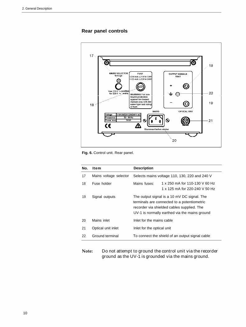
Fig. 6. Control unit. Rear panel.
No. Item Description
17
18
19
20
21
22
Mains voltage selector
Fuse holder
Signal outputs
Mains inlet
Optical unit inlet
Ground terminal
Selects mains voltage 110, 130, 220 and 240 V
Mains fuses: 1 x 250 mA for 110-130 V 60 Hz
1 x 125 mA for 220-240 V 50 Hz
The output signal is a 10 mV DC signal. The
terminals are connected to a potentiometric
recorder via shielded cables supplied. The
UV-1 is normally earthed via the mains ground
Inlet for the mains cable
Inlet for the optical unit
To connect the shield of an output signal cable
Note: Do not attempt to ground the control unit via the recorderground as the UV-1 is grounded via the mains ground.
10

3. Installation
3. Installation
3.1 Site UV-1 should be installed on a stable, flat surface away from all sour-
requirements ces of vibration. The atmosphere should be free of both excess humi-dity and corrosive or contaminated vapours which may form depositson the component in the optical path.
UV-1 can be installed either in a coldroom or at ambient temperaturein the laboratory. To minimise drift, the temperature should be keptconstant. UV-1 optical unit should be positioned away from all sour-ces of draught, heat and direct sunlight. UV-1 should be placed awayfrom any compressor and the fan stream from coldboxes and col-drooms.
The UV-1 may be operated ambient temperatures in the range
0-40 °C (20-30 °C at full specifications).
One mains power point is required to operate UV-1. Separate powerpoints are required for all ancillary equipment, such as recorder.
The power consumption of the monitor is max 20 VA.
3.2 Unpacking Note: It is important that the interference filters and flow cellsshould not be handled during unpacking. For protection ofthese items they should remain in their packing materialsuntil required for use.
Carefully unpack the UV-1. Check the contents against the packinglist supplied. Inspect for any damage that may have occurred duringtransit. Report any damage immediately to the local GE Healthcarerepresentative and to the transport company concerned. Savethe packing material if future transport can be foreseen.
3.3 Electrical The instrument is supplied with mains cables and fuses for both
connections 100-130 V and 220-240 V operation.
1. Ensure that the mains switch (Fig. 5:16) on the front panel ofthe control unit is in the OFF position.
2. Select the correct value of fuse from the fuse kits supplied.For 110-130 V operation, use the 250 mA fuse supplied.For 220-240 V operation, use the 125 mA fuse supplied.Insert the fuse into the fuse cap, and then fit the fuse cap into thefuse holder on the rear panel (Fig. 6:18) of the instrument.
3. Check that the mains voltage selector (Fig. 6:17) on the rearpanel of the control unit is set to the mains voltage in thelaboratory. If necessary, turn with a thick bladed screwdriver themains voltage setting until appropriate setting is indicated in thesmall window.
Note: Use the 220 V setting for a 230 V mains outlet.
11

3. Installation
Mains voltage Voltage selector setting Fuse
3.4 Installationof the filter
110 V 110 250 mA
130 V 130 250 mA
220-230 V 220 125 mA
240 V 240 125 mA
4. Select the mains cable corresponding to your mains outlet.Discard unwanted mains cable immediately. Connect theinstrument to a grounded mains outlet.
Note: Do NOT switch on.
Note: Special care must be taken when handling interferencefilters. DO NOT touch the filter surface. The filters shouldnot allowed to come in contact with any liquid or exposedto temperatures above 60 °C. For directions on cleaninginterference filters, see Section 5.4
1. Select the appropriate filter for the wavelength to be used.
2. Insert the filter and converter or aperture in the optical unit(Fig. 4:7, Fig. 4:8). Each filter is marked with its wavelength andthe letter F. The 280 nm converter is marked 280 C. Theaperture for use with the 254 nm or 405 nm filters is marked 0.
The filter and converter or aperture must be pushed fully home.
Wavelength Filter Converter or Aperture
254 nm 254 F 0
280 nm 280 F 280 C
405 nm 405 F 0
12

3. Installation
3.5 Installation of the flow cell
Monitor UV-1 accepts flow cells for Standard Chromatography, FPLCand industrial applications.
Product Material of Path Total dead Illuminate d Pressure ApplicationCode No. wetted pa rts length volume volume limit area
S-2 Fluoro-plastic, 2 mm 80 µl 2 µl 0.3 MPa Standard19-4840-02 optical quartz (3 bar) Chromatography
HR-10 Fluoro-plastic, 10 mm 24 µl 8.7 µl 1.0 Mpa FPLC, Standard19-6254-02 optical quartz,titanium (10 bar) Chromatography
3 mm Fluoro-plastic, 3 mm 50 µl 3 µl 1.0 MPa Preparative FPLC,19-2503-02 optical quartz (10 bar) Standard Chromatography
10 mm Fluoro-plastic, 10 mm 250 µl 8.7 µl 1.0 MPa Standard19-2504-02 optical quartz (10 bar) Chromatography
5 mm Silicon rubber, 5 mm 0.2 MPa* Industrial scaleIndustrial polypropylene, (2 bar)
19-4510-02 optical quartz
* Flow rate 300 I/h at 0.1 MPa
All flow cell are mounted in the holders, ready to be installed directlyinto the cell housing. Release the locking knob (Fig. 4:6) by turning itagainst the direction of the arrow and insert the flow cell in its holderinto the optical unit. Lock it in position by turning the locking knobfully in the direction of the arrow.
For more information please refer to the instruction sheet suppliedwith the respectively flow cell.
Fig. 7. S-2 flow cell Fig. 8. HR-10 flow cell
Fig. 9. 3 mm flow cell Fig. 10. 10 mm flow cell Fig. 11. Industrial flow cell
13

3. Installation
3.6
3.7
Connecting The optical unit may be placed on the bench or mounted on
the optical unit laboratory scaffolding. For scaffolding mounting, mount the supportrod on the optical unit. The rod may be mounted horizontally orvertically (Fig. 4:9). Tighten the the Allen screw firmly. The opticalunit should be placed as close as possible to the column outlet.Connect the cable from the optical unit to the 1 l-pin socket on theback of the control unit (Fig. 6:21). The plug has a snap lock.To remove it, squeeze the ribbed sides firmly and pull.
Connecting a There is one 10 mV signal output port on the rear panel of the
recorder control unit. It is for use with GE Healthcare recorders or similarinstruments. Connect the output terminals to the input of therecorder, using a signal cable (Fig. 12). Connect the shield of thesignal cable to the grounded terminal port on the rear panel of thecontrol unit. Choose the 10 mV input range on the recorder for fullscale response.
Fig. 12. Connections between the control unit and a dual channel recorder
Recorder REC 102.
14
4. Operation
4.1 Choice ofwavelength
4. Operation
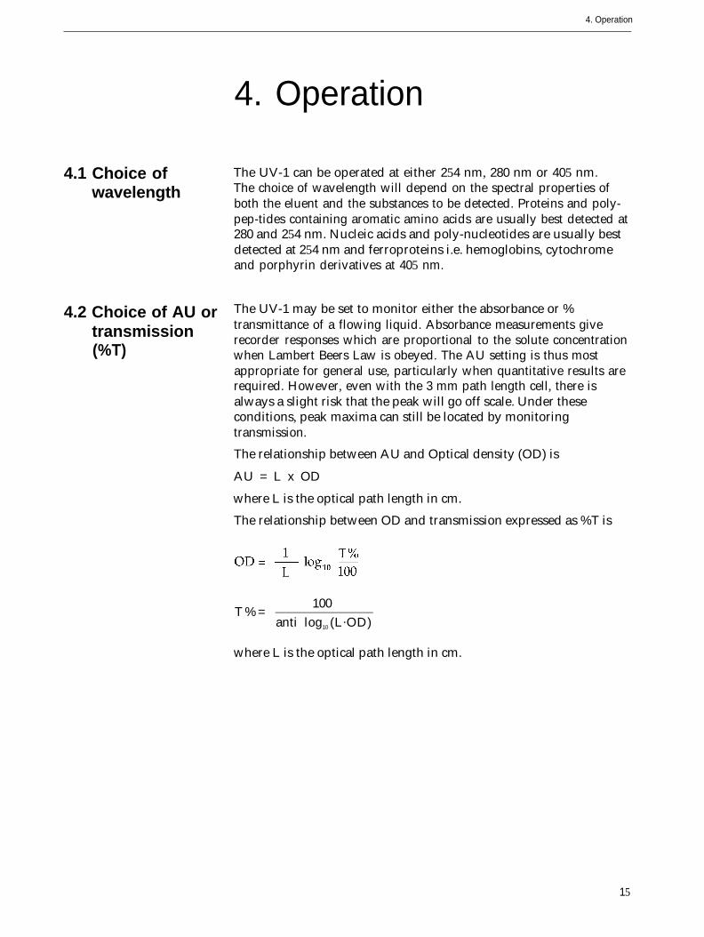
The UV-1 can be operated at either 254 nm, 280 nm or 405 nm.The choice of wavelength will depend on the spectral properties ofboth the eluent and the substances to be detected. Proteins and poly-pep-tides containing aromatic amino acids are usually best detected at280 and 254 nm. Nucleic acids and poly-nucleotides are usually bestdetected at 254 nm and ferroproteins i.e. hemoglobins, cytochromeand porphyrin derivatives at 405 nm.
4.2 Choice of AU or The UV-1 may be set to monitor either the absorbance or %
transmission transmittance of a flowing liquid. Absorbance measurements give
(%T)recorder responses which are proportional to the solute concentrationwhen Lambert Beers Law is obeyed. The AU setting is thus mostappropriate for general use, particularly when quantitative results arerequired. However, even with the 3 mm path length cell, there isalways a slight risk that the peak will go off scale. Under theseconditions, peak maxima can still be located by monitoringtransmission.
The relationship between AU and Optical density (OD) is
AU = L x OD
where L is the optical path length in cm.
The relationship between OD and transmission expressed as %T is
T % =100
anti log10 (L.OD)
where L is the optical path length in cm.
15

4. Operation
4.3 Conversion T% AU OD OD
table T% to AU (3 mm cell) (10 mm cell)
and OD 15
1015202530323540455055606365707579808589909595.597.7
2.0001.3011.0000.8240.6990.6020.5230.5000.4560.3980.3470.3010.2600.2220.2000.1860.1550.1250.1000.0970.0700.0500.0460.0220.0200.010
6.6674.3373.3332.7472.3302.0071.7431.6671.5201.3271.1571.0030.8670.7400.6670.6200.5170.4170.3330.3230.2330.1670.1530.0730.0670.033
2.0001.3011.0000.8240.6990.6020.5230.5000.4560.3980.3470.3010.2600.2220.2000.1860.1550.1250.1000.0970.0700.0500.0460.0220.0200.010
4.4 Start-up Note: Always ensure that all liquid passing through the flow cell
1.
2.
3.
are degassed to prevent any air bubble formation in the cell.Liquids must be filtered to remove any particulate materialand prevent any blockage.
Check that the monitor is correctly installed and that the samplecell is filled with the appropriate eluent. The reference cell maybe left closed with air in the cell unless the UV-1 is used witheluents showing appreciable UV-absorption. In this case thereference cell should be filled with eluent.
If the instrument has been switched off, turn on the mains switch(Fig. 5:16) and refer to Section 4.5, to restabilize the instrument.
Check that the appropriate filter and converter or aperture are inplace and fully inserted.
4.5 Stabilization At normal laboratory temperatures the UV-1 requires 2 hours to
time stabilize sufficiently. When the UV- 1 is in constant use, it isrecommended that it remains switched on. UV- 1 can be switched offwhen not in use for periods of one week or more.
For coldroom operation below 10 °C, install UV-1 in the coldroom atthe desired running temperature at least 12 hours before the start of arun. This is necessary to allow the instrument housing to equilibrateto the temperature of the coldroom. Once equilibration has takenplace, the stabilisation times given for normal temperatures are valid.
16

4. Operation
4.6 Basicoperatingprocedure -AU
4.7 Basicoperatingprocedure -Transmission(%T)
4.8 Shut down
1.
2.
3.
4.
1.
2.
3.
4.
5.
6.
7.
1.
Switch AU/ %T to AU (Fig. 5:13).
Set the range selector (Fig. 5:12) to SHORT and zero therecorder with the recorder zero control.
Set the range selector to 2 and adjust the recorder baseline withthe baseline adjust (Fig. 5:14).
Set the range selector to the appropriate range and readjust therecorder baseline with the baseline adjust (Fig. 5:14). Onlyminor adjustment should be necessary.
Switch AU to %T (Fig. 5:13).
Set the range selector (Fig. 5:12) to SHORT and zero therecorder.
Turn the baseline adjust (Fig. 5:14) fully clockwise.
Set the range selector so that the recorder gives a deflection justgreater than 100%.
Adjust baseline to bring the pen back to 100%.
Exchange the converter for the shutter and zero the recorderwith the recorder zero. This response will correspond to 0%transmission.
Replace the shutter with the converter. This response willcorrespond to 100% transmission. Slight adjustment of baselinemay be required to obtain the response obtained in Step 5.
On completion of the chromatographic run, flush the flow celleither with pure solvent or the buffer used in thechromatographic run. To prevent the deposition of salts fromaqueous buffers, flush the cell with distilled water after use, ifnecessary after disconnecting the column.
Note: Never allow aqueous buffers to dry out in the cell. Eithercontinue to flush through with buffer or leave the cell filledwith distilled water.
2. Leave the UV-1 switched on. The monitor should only beswitched off if it is not going to be used again for more than oneweek.
17
5. Maintenance
5. Maintenance
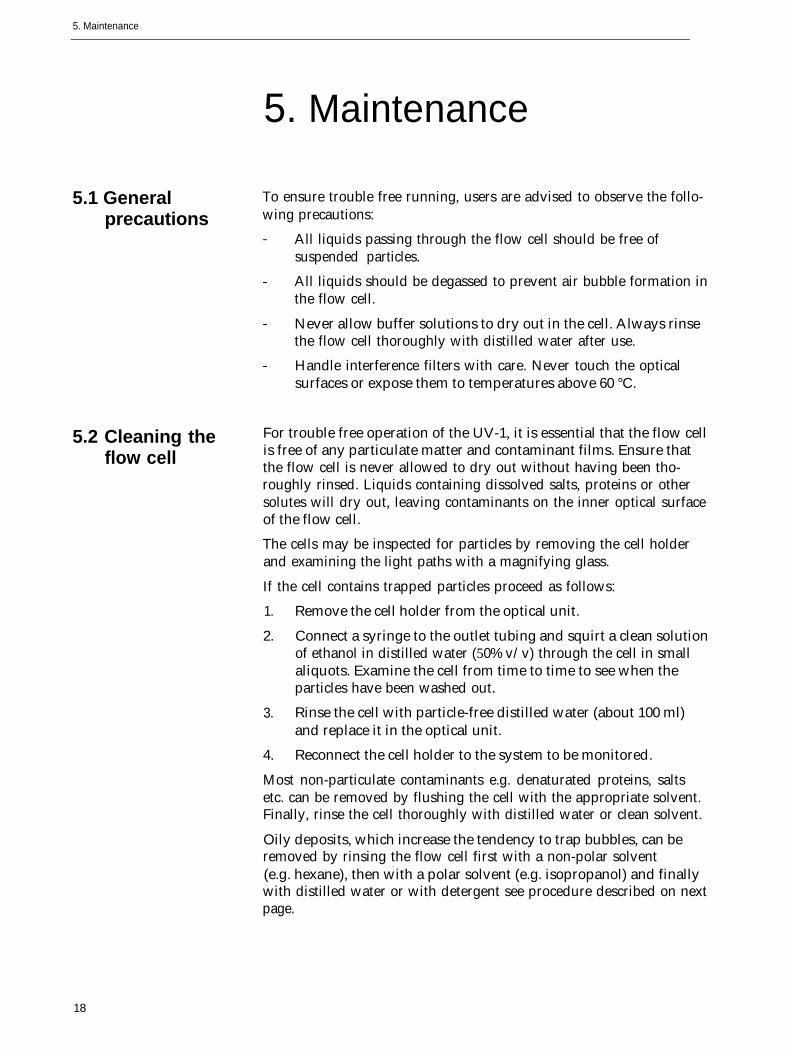
5.1 General To ensure trouble free running, users are advised to observe the follo-
precautions wing precautions:
All liquids passing through the flow cell should be free ofsuspended particles.
All liquids should be degassed to prevent air bubble formation inthe flow cell.
Never allow buffer solutions to dry out in the cell. Always rinsethe flow cell thoroughly with distilled water after use.
Handle interference filters with care. Never touch the opticalsurfaces or expose them to temperatures above 60 °C.
5.2 Cleaning the For trouble free operation of the UV-1, it is essential that the flow cell
flow cell is free of any particulate matter and contaminant films. Ensure thatthe flow cell is never allowed to dry out without having been tho-roughly rinsed. Liquids containing dissolved salts, proteins or othersolutes will dry out, leaving contaminants on the inner optical surfaceof the flow cell.
The cells may be inspected for particles by removing the cell holderand examining the light paths with a magnifying glass.
If the cell contains trapped particles proceed as follows:
1. Remove the cell holder from the optical unit.
2. Connect a syringe to the outlet tubing and squirt a clean solutionof ethanol in distilled water (50% v/v) through the cell in smallaliquots. Examine the cell from time to time to see when theparticles have been washed out.
3. Rinse the cell with particle-free distilled water (about 100 ml)and replace it in the optical unit.
4. Reconnect the cell holder to the system to be monitored.
Most non-particulate contaminants e.g. denaturated proteins, saltsetc. can be removed by flushing the cell with the appropriate solvent.Finally, rinse the cell thoroughly with distilled water or clean solvent.
Oily deposits, which increase the tendency to trap bubbles, can beremoved by rinsing the flow cell first with a non-polar solvent(e.g. hexane), then with a polar solvent (e.g. isopropanol) and finallywith distilled water or with detergent see procedure described on nextpage.
18

5. Maintenance
Cleaning with detergent:
●
1. Remove the cell holder from the optical unit.
2. Pump undiluted cleaning detergent through the cell for at least2 hours.
3. Rinse the cell witha) distilled water (100 ml)b) ethanol/distilled water (50% v/v, 100 ml)c) distilled water (100 ml)
4. Replace the cell in the optical unit and reconnect the system tobe monitored.
Cleaning with chromic acid:
1. Prepare fresh chromic acid by adding concentrated sulphuricacid (100 ml) to a saturated solution of sodium dichromate(3.5 ml).
Warning: Chromic acid is extremly corrosive. Treat spillsimmediately with a large excess of water.
2. Remove the cell holder from the optical unit.
3. Connect a glass syringe to the outlet side of the cell and carefullydraw chromic acid into the cell. Do not draw acid into thesyringe.
4. Allow the acid to remain in the cell for 10-20 minutes. Longerexposures (several hours) will not harm the cell.
5. Eject the cleaning solution carefully without splashing and rinsethe cell with
a) distilled water (100 ml)b) ethanol/distilled water (50% v/v, 100 ml)c) distilled water (100 ml)
6. Replace the cell in the optical unit and reconnect the system tobe monitored.
5.3 Changing the To change the flow cell, follow the instructions below.
flow cell 1. Switch the UV-1 off at the control unit.
2. Disconnect the cell from the system being monitored and emptyit of liquid.
3. Remove the cell holder from the optical unit.
4. Remove the black cover by undoing the screw on top of the cellholder. The tubing connections to the cell are now accessible.Note their positions (Fig. 13).
5. Loosen the connections using the tool provided. Do not undo.
6. The cell may now be slipped out.
7. Before inserting the new cell make sure the tubing ends do notprotrude into the cell compartment.
19

8. Insert the new cell, being careful not to touch either of the optical surfaces. See that the inlet and outlet ports are correctly aligned.9. Retighten the screw washers with the tool provided. Do not use excessive force.
10. Check for leakage.11. Replace the black cover.
For optimum performance, it is essential that the interference filtersare clean and free of any particulate material. Do not touch the inter-ference filters. Should the filter become contaminated with dust,fingerprints or oil, proceed as follows:- Carefully take out the filter without touching or scratching the surface.- Use lens cleaning tissue dipped in ethanol to gently clean both sides of the filter surface.- Place the clean filter back to the UV-1 or its box.- Interference filters should never be exposed to temperatures above 60 °C
Clean all other optical surfaces by wiping the surface with clean, lint-free cloth, moistened with carbon tetrachloride, ethanol, or anothersuitable pure solvent.
Wipe the instrument regularly with a damp cloth. Let the instrumentdry completely before use.
Before performing this test see that the filter is clean, that the cell isclean and free of bubbles or particles and that the cell holder iscorrectly inserted and locked in position.1. Insert the aperture and filter for 254 nm operation or the converter and filter for 280 nm operation.2. Set AU / %T to % T.3. Set the recorder to the 100 mV range.
20
5. Maintenance
Reference out Sample out
Reference in Sample in
5.4 Interference filters
5.5 Other optical surfaces
5.6 Instrument housing
5.7 Lamp and optical system test
Fig. 13. Flow cell interior showing tubing connections.

4. Set the range selector to SHORT and zero the recorder.
5. Set the range selector as follows: 254 nm, range 1 280 nm, range 0.2
6. Turn Zero fully clockwise.
Response 8 mV or greater: the lamp is operating properly and theoptical system is clean.
Response 0 mV or very close to 0 mV: Contact a GE Healthcarerepresentative.
Response less than 8 mV but not very close to zero: check that thecell and filter is clean. If fault persists, the filter or lamp may requirechanging (see Section 5.7).
The low pressure mercury lamp has an expected lifetime of approx.8000 hours. Before changing the lamp, carry out the tests described inSection 5.6. If the tests indicates an aging lamp, proceed as follows.
l. Disconnect the control unit from the mains supply and disconnect the optical unit from the control unit.Warning: The control unit must be disconnected from the mains
and from the optical unit. If the UV-Iamp is brokenmake sure that all mercury is removed.
2. Remove the cell holder.3. Remove the two screws and locking washers which secure the case of the optical unit to the bottom of the chassis.
4. Loosen the two Philips screws until the top of the case can be lifted clear of the catches.
5. Pull the case forward, and remove it (Fig. 14).
5.8 Changing the mercury lamp
5. Maintenance
Fig. 14. Optical unit interior with lamp driver circuit board removed
21
Screw
Stop ring
Lamp Screw
5. Maintenance
5.9
6. Use an Allen key (2.5 mm) to unscrew the upper of the twoscrews securing the lamp holder and the lamp. Note carefully thepositions of the insulation sleeve and washer.
7. Disconnect the lamp from the PC-board.
8. Bend the upper part of the lamp holder slightly (2-3 mm)upwards and withdraw the mercury lamp from it by gentlypulling the metal socket.
9. Insert the new mercury lamp and connect it to the PC-board.
10. Remount the upper lamp holder screw, ensuring that theinsulations are correctly mounted, reinstall the cell holder andperform the maximum light adjustment described in Section 5.8.
Mercury lamp- maximumlightadjustment
Warning: During this adjustment stray light may escape from the
1.
2.
3.
4.
5.
6.
7.
8.
9.
10.
11.
12.
UV source and protective glasses must be worn.
Connect the optical unit to the control unit and plug into themains supply.
Switch on the instrument and allow to warm up for about10 minutes.
Insert a filter and the corresponding converter or aperture.
Connect the control unit to a recorder with a full scale responseof 50 mV.
Set the range selector to SHORT and zero the recorder.
Set AU/ %T to % T and turn the baseline adjust fully clockwise.
Select a range giving a pen deflection of approx. 50 % and thenrotate the lamp around its longitudinal axis until maximum pendeflection occurs.
Set the range selector to SHORT and adjust the recorder zero tobring the pen to the centre of the chart. Mark this pen position.
Set the range selector to 2 and set AU/ % T to AU.
Adjust the baseline control to its mid-position, five full turnsfrom either end of its range, by means of a tool, ie. an adjustablespanner.
If necessary, adjust the lamp by turning it slightly to bring thepen back to the position marked in step 8.
Reassemble the optical unit.
22

6. Trouble-shooting
6. Trouble-shootingThe UV-1 Monitor has been designed for trouble-free use. If good chromatographic practice isfollowed, very little difficulty should be experienced. Clean optical surfaces are essential if low noiselevels are to be maintained. The following check list of the most frequent problems is meant to be aguide in trouble-shooting. If the checks in this section are executed and the UV-1 still does not workproperly, consult your local GE Healthcare representative.
Symptom Cause Remedy
Pilot light does not light 1. Mains cord not plugged in Check that mains cord is plugged in2. Fuse blown Replace fuse. If fuse blows again
immediately consult GE Healthcare representative3. No voltage at mains socket Check by plugging table lamp in
Pilot light on, no recorder 1.response
2.
3.4.5.6.
7.8.
Optical unit not connectedto control unitControl unit not connectedto recorderRecorder not operatingRecorder zero not set correctlyRecorder range incorrectWrong filter
Filter not pushed in fullyShutter in place
Check that connecting cable isplugged inCheck connection between outputterminals and recorderCheck recorder functionZero recorderSet recorder range to 10 mVCheck that the filter corresponds toconverter or aperturePush in filterRemove shutter and insert converteror aperture as appropriate
Excessive noise 1.2.
3.
4.5.6.
7.8.8.9.
Poor ground contactExcess noise on mains supply
Recorder connectionsincorrectRecorder range incorrectDirty cellDeposits on optical surfaces
Solvent with high UV absorptionLamp not warmed upBubbles passing through the cellAging lamp
Check contact to groundUse alternative power source orremove source of disturbanceCheck connection betweenoutput terminals and recorderSet recorder on 10 mV rangeClean cellClean filter and converterRelocate optical unit in a clean environmentChange to a more suitable solvent2 h warm-up, in cold room 12 hDe-gas solvent. Check for leaksCheck lamp and replace if necessary
Excessive baseline drift 1.2.
3.
4.5.
Variable absorbance gradient Compensate by use of reference cellContaminated solvent Use fresh solvent. Check that plastic tubing
does not leak UV absorbing substancesLarge variation in ambient Relocate optical unit or removetemperature source of temperature changeInstrument warm-up Allow 2 hours warm-upCondensation forming in Flush reference cell with dry gas orempty reference fill it with the appropriate solvent
Long term noise, 1. Variations in ambient temperature Relocate optical unit or protectoften regular waves in especially in cold room from draughtrecorder reponse 2. Flow rate variations Check pump system and column packing
3. Poor ground contact Check contact to ground4. Bubbles passing cell De-gas solvent. Check for leaks5. Dirty cell Clean cell6. Deposits on optical surfaces Clean filter and converter
Relocate optical unit in a clean environment
23

7. Technical Specifications
7. Technical SpecificationsWavelength rangeLamp
Filters
Operating modesFull scale rangesNoise
Linearity
Temperature drift
Long term drift
Time constantRecorder outputEnvironment
Power consumptionPower supply, voltage
frequencyDimensions (LxWxD)
Weight
254 nm, 280 nm and 405 nmHg lamp: for 254, 280, and 405 nmLife time lamp: 8000 hours
converter: 2000 hoursInterference. Stray light maximum 0,1 %at 254 nm, maximum 0.8% at 280 nmAU or Transmission0.01, 0.02, 0.05, 0.1, 0.2, 0.5, 1 or 2 AUFS 4 x 10⁻⁵ AU peak to peak maximum at254 nm (dry cell) 2 x 10⁻⁴ AU peak to peak (typical at254 nm in flowing liquid) 5 x 10⁻⁴ AU peak to peak (typical at280 nm flowing liquid)At 254 nm, better than ± 3% to 2 AUAt 280 nm, better than ± 5% to 1 AU 2 x 10⁻⁴ AU/°C typical with dry cell at254 nm <2 x 10⁻³ AU/°C typical with dry cellat 280nm 1 x 10⁻⁴ AU/h at 254 nm, constanttemperature after 2 hours warm-up 4 x 10⁻⁴ AU/h at 280 nm, constanttemperature after 2 hours warm-up1.5 s to 90% of FSD at all ranges0-10 mV0 to +40 °C, 20-95 % relative humidity,84-106 kPa (840-1060 mbar) atmosphericpressure20 VA100/120/220-230/240 V-50-60 HzControl unit: 180x145x75 mmOptical unit: 180x145x75 mmControl unit: 1.6 kg Optical unit: 1.7 kg
EMC standards This product meets the requirement of the EMC Directive 89/336/EEC through the harmonized standardsEN 50081-2 (emission) and EN 50082-1 (immunity)
Note: This is a class A product. In a domestic environment this product may cause radio interference in whichcase the user may be required to take adequate actions.
Note: The declaration of conformity is valid for the instrument when it is:
● used in laboratory locations
● used in the same state as it was delivered from GE Healthcare Bio-Sciences AB except for alteration described in theUser Manual
● used as “stand alone” unit or connected to other CE labelled GE Healthcare products or other products asrecommended.
Safety standards This product meets the requirement of the Low Voltage Directive (LVD) 73/23/EEC through the harmonizedstandard EN 61010-1.
24

8. Accessories and Spare Parts
8. Accessories andSpare Parts
Please order accessories and spare parts according to the designationand code numbers given below.
Designation
Filters
Filter kit, 254 nm
Filter kit, 280 nm
Filter kit, 405 nm
Aperture
Converter 280 nm
Flow cells
Flow cell S-2 complete
with measuring cell
Flow cell 10 mm complete
with measuring cell
Flow cell 3 mm
with measuring cell
Flow cell HR-10
with measuring cell
Flow cell large volume
with measuring cell
Measuring cell, 3 mm
Measuring cell, 10 mm
Accessories and Spare parts
UV lamp complete
Tubing and fittings
Tubing, PTFE, (pack of 5 m)
Shutter
Allen key
Signal input cable
Mains cable, US
Mains cable, EU
Fuse holder for 125 mA fuse
Fuse holder for 250 mA fuse
Fuse, 125 mA for 220 V
Fuse, 250 mA for 110 V
Code No.
19-2432-01
19-2433-01
19-4724-01
19-2492-01
19-2486-01
19-4840-02
19-2504-02
19-2503-02
19-6254-02
19-4510-02
19-2525-01
19-2524-01
19-3807-01
19-2505-01
19-0041-01
19-2491-01
19-0379-01
19-2853-01
19-2447-01
19-2448-01
19-2925-01
19-2926-01
19-2367-01
19-2368-01
Pieces
1
1
1
1
1
1
1
1
1
1
1
1
1
1
1
1
1
1
1
1
1
1
5
5
25

Prin
ted
in S
wed
en b
y S
NIT
S &
DE
SIG
N A
B/V
ästr
a A
ros
Try
cker
i, N
ov 1
996
![Control Unit (Ohjausyksikkö - cs.helsinki.fi · Control Unit (Ohjausyksikkö) Ch 15-16 [Sta10] n Micro-operations n Control signals (Ohjaussignaalit) n Hardwired control (Langoitettu](https://img.dokumen.tips/doc/110x75/5b908c3d09d3f28a7e8c2ebf/control-unit-ohjausyksikkoe-cs-control-unit-ohjausyksikkoe-ch-15-16-sta10.jpg)