Embed Size (px)
Citation preview
© UGS Corp. 2007. All rights reserved. UGS PLM Software
NX Advanced FEM (Version NX 5)
2
AimsThere are 225 slides in this file, it is NOT the expectation that you show all of them to the prospect/customer
The aim here is to provide a deck of slides that you can choose to “pick and mix” from to show a workflow or solution that is appropriate to yourrequirements
These slides describe the “Core” functionality. I have skipped some icons/functions as they are only applicable for one of the add-on applications.
These can be used as the build up for a presentation on one of the add-on applications like Laminates, Response Simulation, Thermal, Flow etc
As these slides are all built to a consistent style, doing a “pick and mix” will still result in a clean looking presentation
Please note that after the Solver Language Environment slides, everything is NX Nastran specific
Please provide any enhancements or suggestions to [email protected] (+44 1462 44 5029)
Slides 2 – 6 are not intended for Public useSlides 2 – 6 are not intended for Public use
3
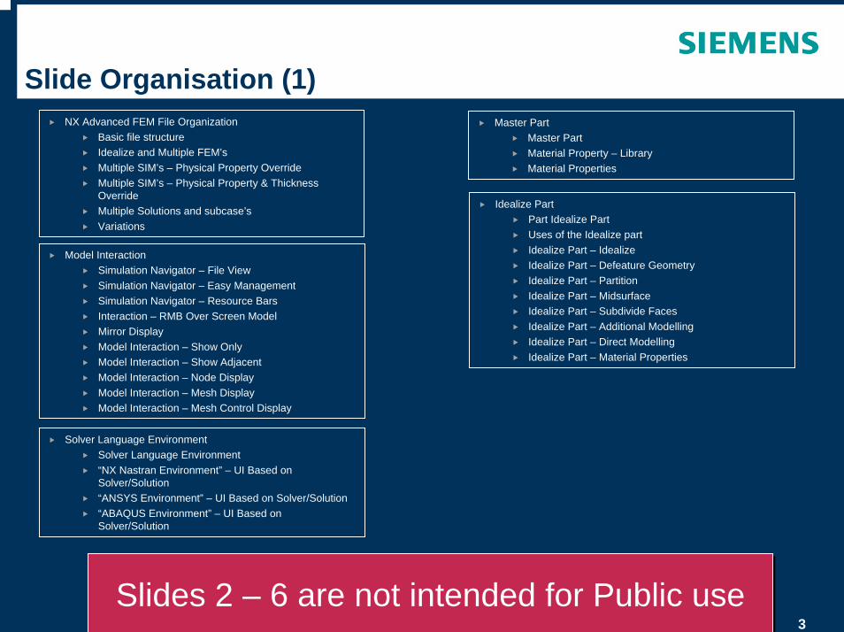
Slide Organisation (1)NX Advanced FEM File Organization
Basic file structureIdealize and Multiple FEM’sMultiple SIM’s – Physical Property OverrideMultiple SIM’s – Physical Property & Thickness OverrideMultiple Solutions and subcase’sVariations
Idealize PartPart Idealize PartUses of the Idealize partIdealize Part – Idealize Idealize Part – Defeature GeometryIdealize Part – PartitionIdealize Part – MidsurfaceIdealize Part – Subdivide FacesIdealize Part – Additional ModellingIdealize Part – Direct ModellingIdealize Part – Material Properties
Master PartMaster PartMaterial Property – LibraryMaterial Properties
Model InteractionSimulation Navigator – File ViewSimulation Navigator – Easy ManagementSimulation Navigator – Resource BarsInteraction – RMB Over Screen ModelMirror DisplayModel Interaction – Show OnlyModel Interaction – Show AdjacentModel Interaction – Node DisplayModel Interaction – Mesh DisplayModel Interaction – Mesh Control Display
Solver Language EnvironmentSolver Language Environment“NX Nastran Environment” – UI Based on Solver/Solution“ANSYS Environment” – UI Based on Solver/Solution“ABAQUS Environment” – UI Based on Solver/Solution
Slides 2 – 6 are not intended for Public useSlides 2 – 6 are not intended for Public use
4
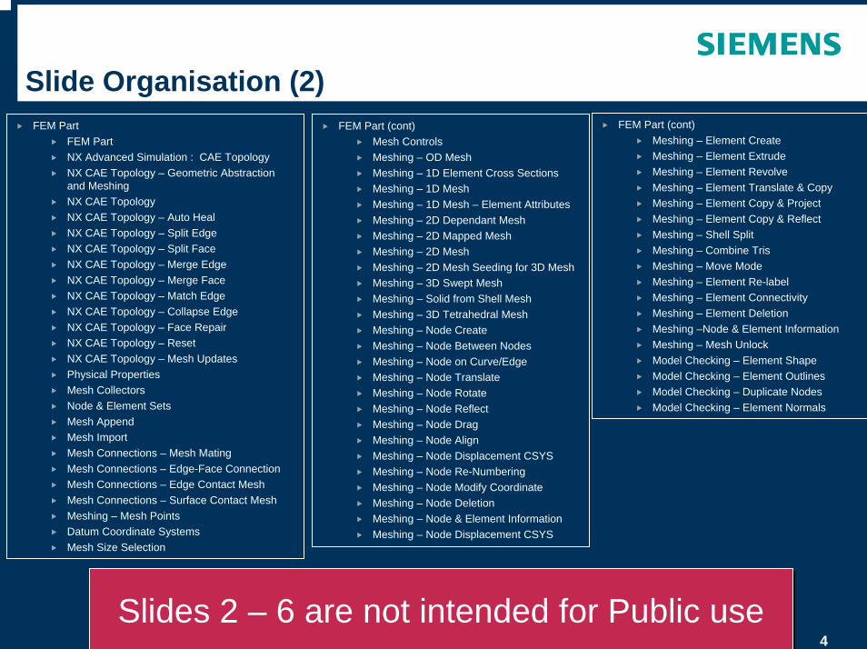
Slide Organisation (2)FEM Part (cont)
Mesh ControlsMeshing – OD MeshMeshing – 1D Element Cross SectionsMeshing – 1D MeshMeshing – 1D Mesh – Element AttributesMeshing – 2D Dependant MeshMeshing – 2D Mapped MeshMeshing – 2D MeshMeshing – 2D Mesh Seeding for 3D MeshMeshing – 3D Swept MeshMeshing – Solid from Shell MeshMeshing – 3D Tetrahedral MeshMeshing – Node CreateMeshing – Node Between NodesMeshing – Node on Curve/EdgeMeshing – Node TranslateMeshing – Node RotateMeshing – Node ReflectMeshing – Node DragMeshing – Node AlignMeshing – Node Displacement CSYSMeshing – Node Re-NumberingMeshing – Node Modify CoordinateMeshing – Node DeletionMeshing – Node & Element InformationMeshing – Node Displacement CSYS
FEM PartFEM PartNX Advanced Simulation : CAE TopologyNX CAE Topology – Geometric Abstraction and Meshing NX CAE TopologyNX CAE Topology – Auto HealNX CAE Topology – Split EdgeNX CAE Topology – Split FaceNX CAE Topology – Merge EdgeNX CAE Topology – Merge FaceNX CAE Topology – Match EdgeNX CAE Topology – Collapse EdgeNX CAE Topology – Face RepairNX CAE Topology – ResetNX CAE Topology – Mesh UpdatesPhysical PropertiesMesh CollectorsNode & Element SetsMesh AppendMesh ImportMesh Connections – Mesh Mating Mesh Connections – Edge-Face ConnectionMesh Connections – Edge Contact MeshMesh Connections – Surface Contact MeshMeshing – Mesh PointsDatum Coordinate SystemsMesh Size Selection
Slides 2 – 6 are not intended for Public useSlides 2 – 6 are not intended for Public use
FEM Part (cont)Meshing – Element CreateMeshing – Element ExtrudeMeshing – Element RevolveMeshing – Element Translate & CopyMeshing – Element Copy & ProjectMeshing – Element Copy & ReflectMeshing – Shell SplitMeshing – Combine TrisMeshing – Move ModeMeshing – Element Re-label Meshing – Element ConnectivityMeshing – Element DeletionMeshing –Node & Element InformationMeshing – Mesh Unlock Model Checking – Element ShapeModel Checking – Element OutlinesModel Checking – Duplicate NodesModel Checking – Element Normals
5
Slide Organisation (3)SIM Part – Pre-Processing
Modeling Objects – ManagerModeling Objects – Contact Set ParametersModeling Objects – Strategy ParametersModeling Objects – Real Eigenvalue, Lanczos & HouseholderModeling Objects – Forcing Frequencies – Direct & ModalModeling Objects – Time StepModeling Objects – Structural Output RequestsModeling Objects – Solution ParametersModeling Objects – System CellsSurface to Surface – ContactSurface to Surface – GlueLoads – ForceLoads – BearingLoads – TorqueLoads – MomentLoads – PressureLoads – Hydrostatic PressureLoads – GravityLoads – CentrifugalLoads – Constant TemperatureLoads – Nodal Force LocationConstraints – User DefinedConstraints – Enforced DisplacementConstraints – Fixed, Translation & RotationConstraints – Simply Supported
Slides 2 – 6 are not intended for Public useSlides 2 – 6 are not intended for Public use
SIM Part – Pre-Processing (cont)Constraints – SliderConstraints – Pinned Constraints – CylindricalConstraints – RollerConstraints – SymmetricConstraints – Anti-SymmetricConstraints – VelocityConstraints – AccelerationConstraints – Automatic CouplingConstraints – Manual CouplingConstraints – Enforced Motion LocationBoundary Condition Symbol Display ControlsPhysical Property OverridesCustom Units & Units ConverterUnit SelectionBoundary Condition Magnitude – Table FieldBoundary Condition Magnitude – Function FieldSolutionSolution – Containers and Re-using DataSolution – Subcase ManagementSolution – AttributesSolution – ParametersSolution – Comprehensive CheckSolution – Report Before SolveSolution – Solve the Active Solution
6
Slide Organisation (4)SIM Part – Post-Processing
NX – Integrated Post ProcessingResults – SelectionResults – AnimationResults – Post View DisplayResults – Post View Color BarResults – Post View Edges & FacesResults – IdentifyResults – Annotation MarkersResults – Previous / Next Mode or IterationResults – Post Views & TemplatesResults – Multiple ViewportsResults – Post View OverlayPlotting PathsGraph StyleGraph ProbingGraph WindowingSolution Report – After SolveExport Visualisation Files
Simulation Customer DefaultsCustomer Defaults – GeneralCustomer Defaults – Model PreparationCustomer Defaults – Mesh DisplayCustomer Defaults – Node & Element DisplayCustomer Defaults – Mesh ControlsCustomer Defaults – Boundary Condition DisplayCustomer Defaults – Threshold Values Nastran Customer Defaults – MeshingCustomer Defaults – AnalysisCustomer Defaults – Post Processor
Slides 2 – 6 are not intended for Public useSlides 2 – 6 are not intended for Public use
© UGS Corp. 2007. All rights reserved. UGS PLM Software
NX Advanced FEM File Organisation
8
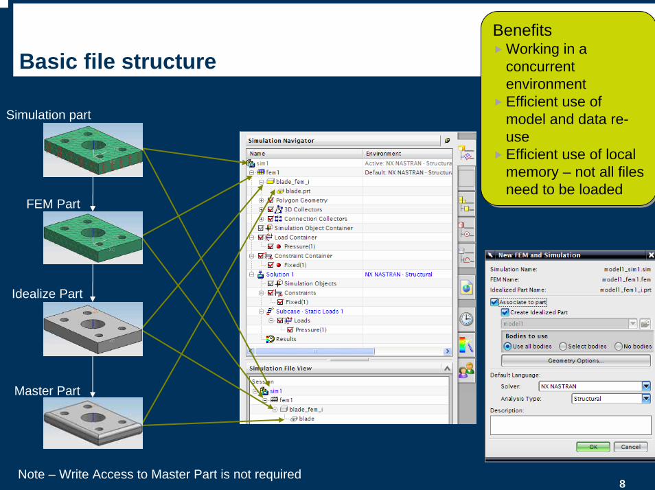
Simulation part
FEM Part
Idealize Part
Master Part
Basic file structure
Note – Write Access to Master Part is not required
BenefitsWorking in a concurrent environmentEfficient use of model and data re-useEfficient use of local memory – not all files need to be loaded
BenefitsWorking in a concurrent environmentEfficient use of model and data re-useEfficient use of local memory – not all files need to be loaded
9
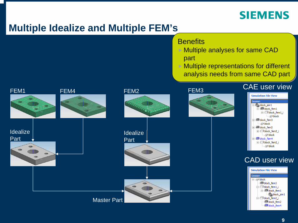
Multiple Idealize and Multiple FEM’s
FEM2 FEM3
Master Part
Idealize Part
Idealize Part
CAE user view
CAD user view
FEM1 FEM4
BenefitsMultiple analyses for same CAD partMultiple representations for different analysis needs from same CAD part
BenefitsMultiple analyses for same CAD partMultiple representations for different analysis needs from same CAD part
10
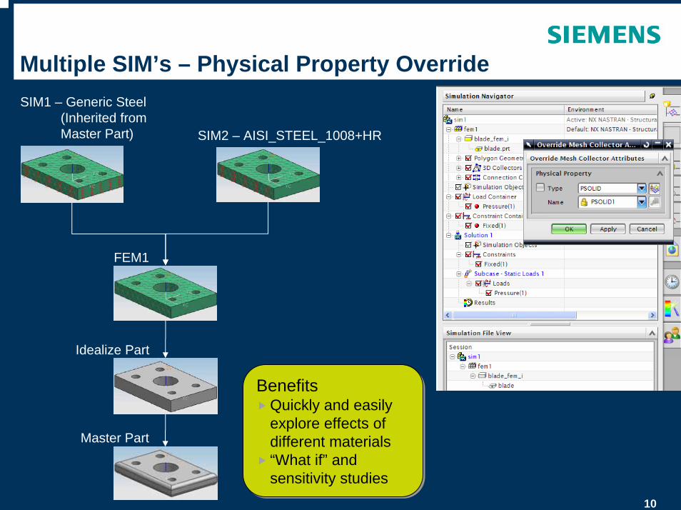
Multiple SIM’s – Physical Property OverrideSIM1 – Generic Steel
(Inherited from Master Part) SIM2 – AISI_STEEL_1008+HR
FEM1
Idealize Part
Master Part
BenefitsQuickly and easily explore effects of different materials“What if” and sensitivity studies
BenefitsQuickly and easily explore effects of different materials“What if” and sensitivity studies
11
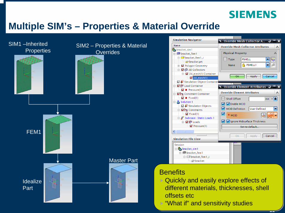
Multiple SIM’s – Properties & Material Override
FEM1
Idealize Part
Master Part
SIM2 – Properties & MaterialOverrides
SIM1 –Inherited Properties
BenefitsQuickly and easily explore effects of different materials, thicknesses, shell offsets etc“What if” and sensitivity studies
BenefitsQuickly and easily explore effects of different materials, thicknesses, shell offsets etc“What if” and sensitivity studies
12
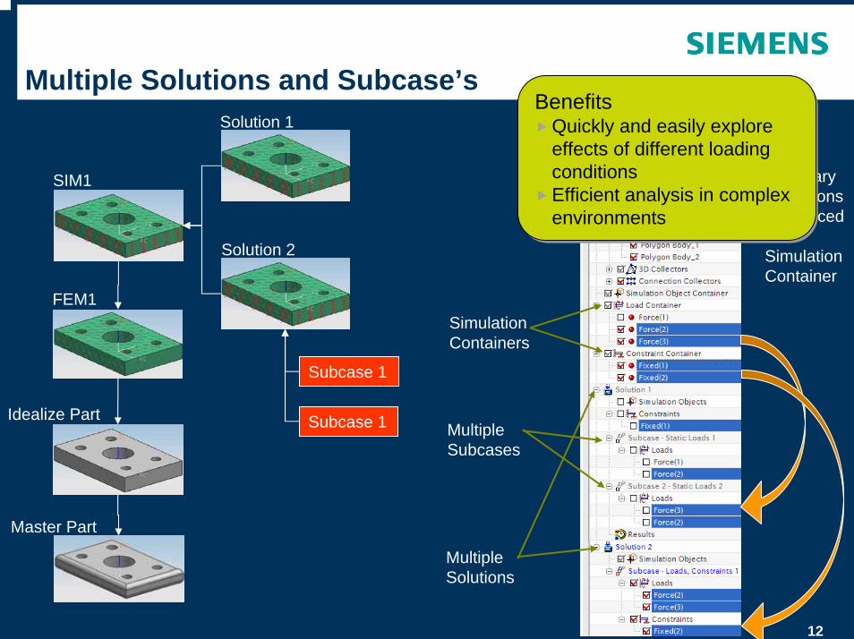
Multiple Solutions and Subcase’s
Simulation Containers
Boundary Conditions referenced from Simulation Container
SIM1
FEM1
Idealize Part
Master Part
Solution 1
Solution 2
Subcase 1
Subcase 1
BenefitsQuickly and easily explore effects of different loading conditionsEfficient analysis in complex environments
BenefitsQuickly and easily explore effects of different loading conditionsEfficient analysis in complex environments
Multiple Solutions
Multiple Subcases
13
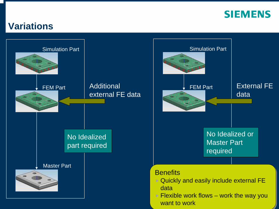
Variations
FEM Part
Master Part
Simulation Part
FEM Part
Simulation Part
No Idealized part required
No Idealized or Master Part required
External FE data
Additional external FE data
BenefitsQuickly and easily include external FE dataFlexible work flows – work the way you want to work
BenefitsQuickly and easily include external FE dataFlexible work flows – work the way you want to work
© UGS Corp. 2007. All rights reserved. UGS PLM Software
Model Interaction
15
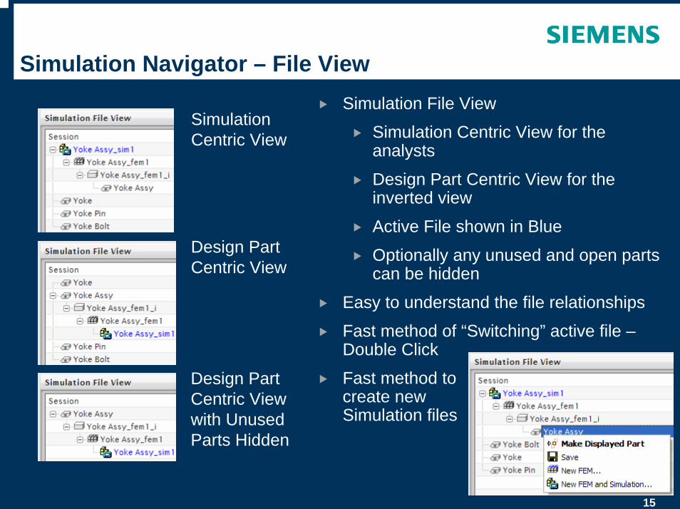
Simulation Navigator – File ViewSimulation File View
Simulation Centric View for the analysts
Design Part Centric View for the inverted view
Active File shown in Blue
Optionally any unused and open parts can be hidden
Easy to understand the file relationships
Fast method of “Switching” active file –Double Click
Fast method to create new Simulation files
Simulation Centric View
Design Part Centric View
Design Part Centric View with Unused Parts Hidden

16
Simulation Navigator – Easy Management
Active Solver Environment
Simulation Centric File View
Mesh Out-of-Date Symbol
Hide/Show of Polygon models and Meshes during selection
Containers to Organise related CAE Data
Drag ‘n’Drop from Containers to Solution

17
Simulation Navigator – Easy ManagementRMB Operations Directly from Navigator
18
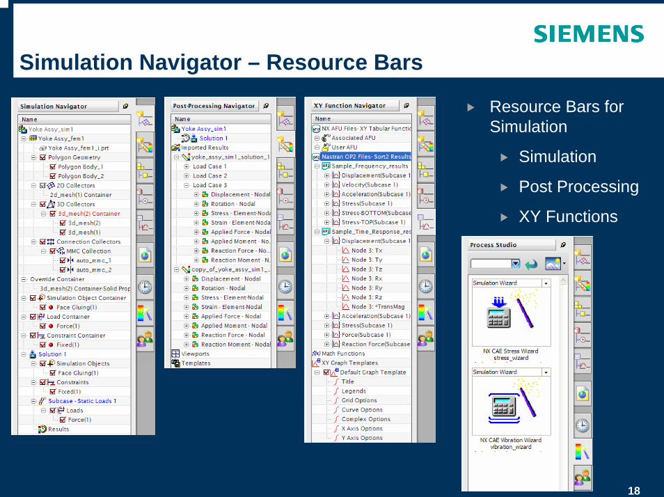
Simulation Navigator – Resource Bars
Resource Bars for Simulation
Simulation
Post Processing
XY Functions
19
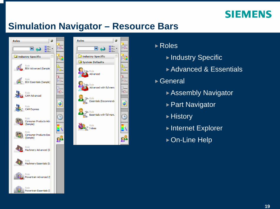
Simulation Navigator – Resource Bars
Roles
Industry Specific
Advanced & Essentials
General
Assembly Navigator
Part Navigator
History
Internet Explorer
On-Line Help
20
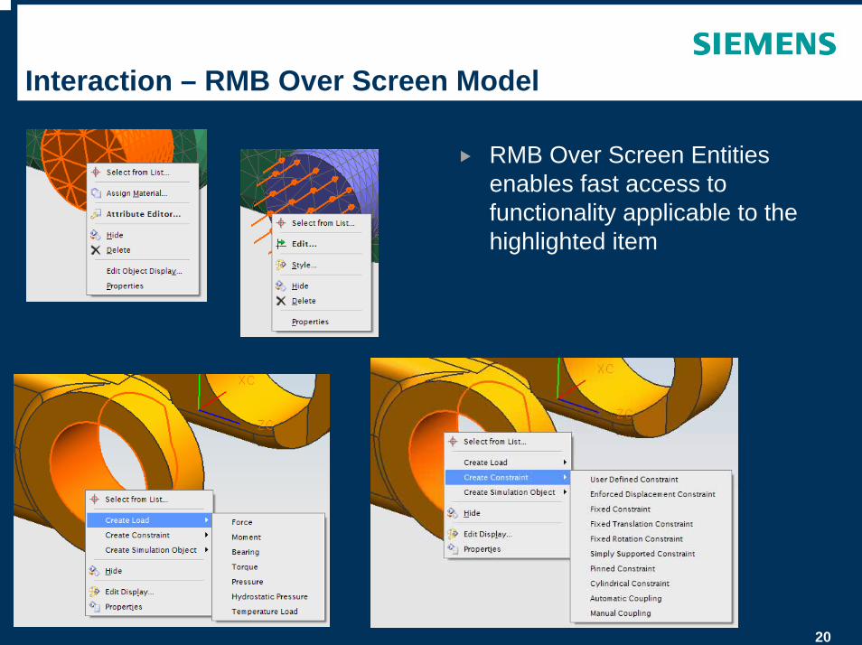
Interaction – RMB Over Screen Model
RMB Over Screen Entities enables fast access to functionality applicable to the highlighted item
21
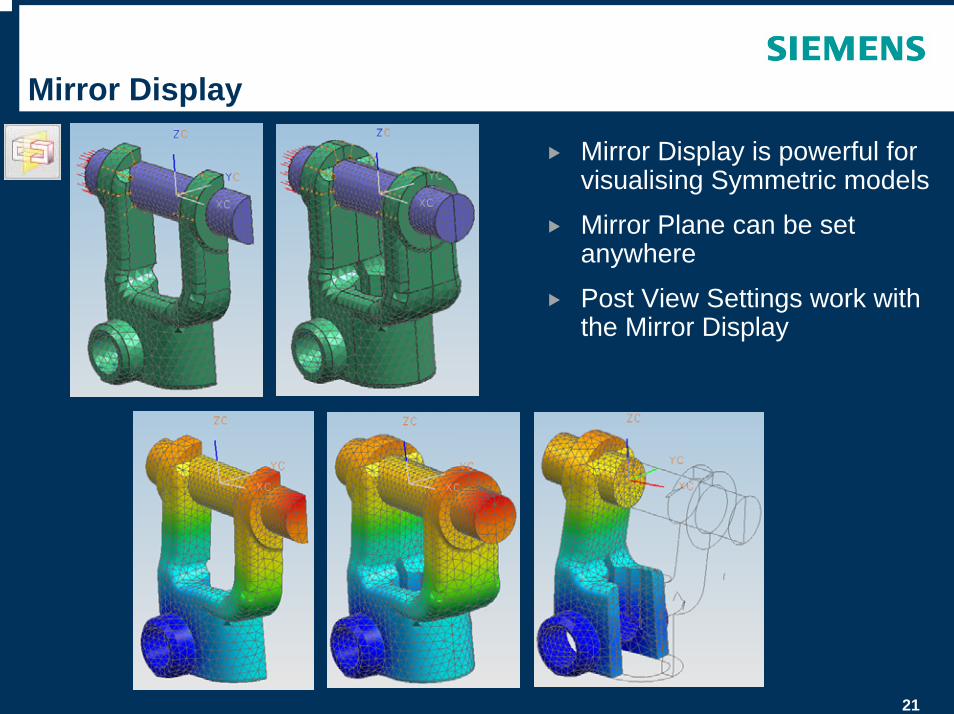
Mirror Display
Mirror Display is powerful for visualising Symmetric models
Mirror Plane can be set anywhere
Post View Settings work with the Mirror Display
22
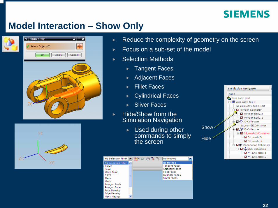
Model Interaction – Show OnlyReduce the complexity of geometry on the screenFocus on a sub-set of the modelSelection Methods
Tangent FacesAdjacent FacesFillet FacesCylindrical FacesSliver Faces
Hide/Show from the Simulation Navigation
Used during other commands to simply the screen
Show
Hide

23
Model Interaction – Show Adjacent
Show Adjacent to “grow” visible related geometrySelection Methods
Tangent FacesAdjacent FacesFillet FacesCylindrical FacesSliver Faces
24
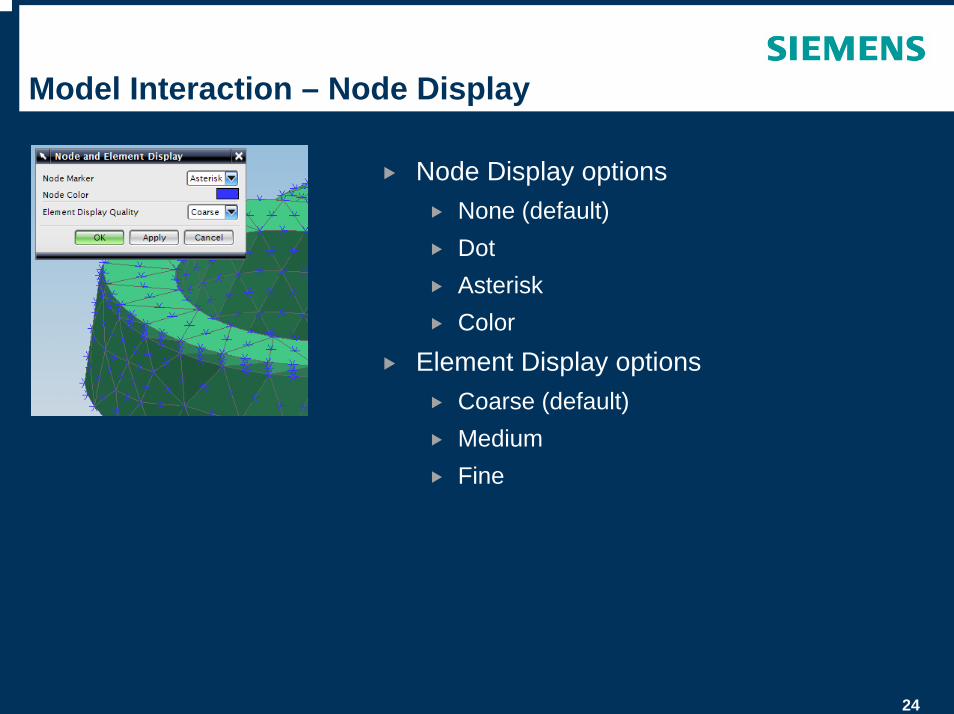
Model Interaction – Node Display
Node Display optionsNone (default)DotAsteriskColor
Element Display optionsCoarse (default)MediumFine
25
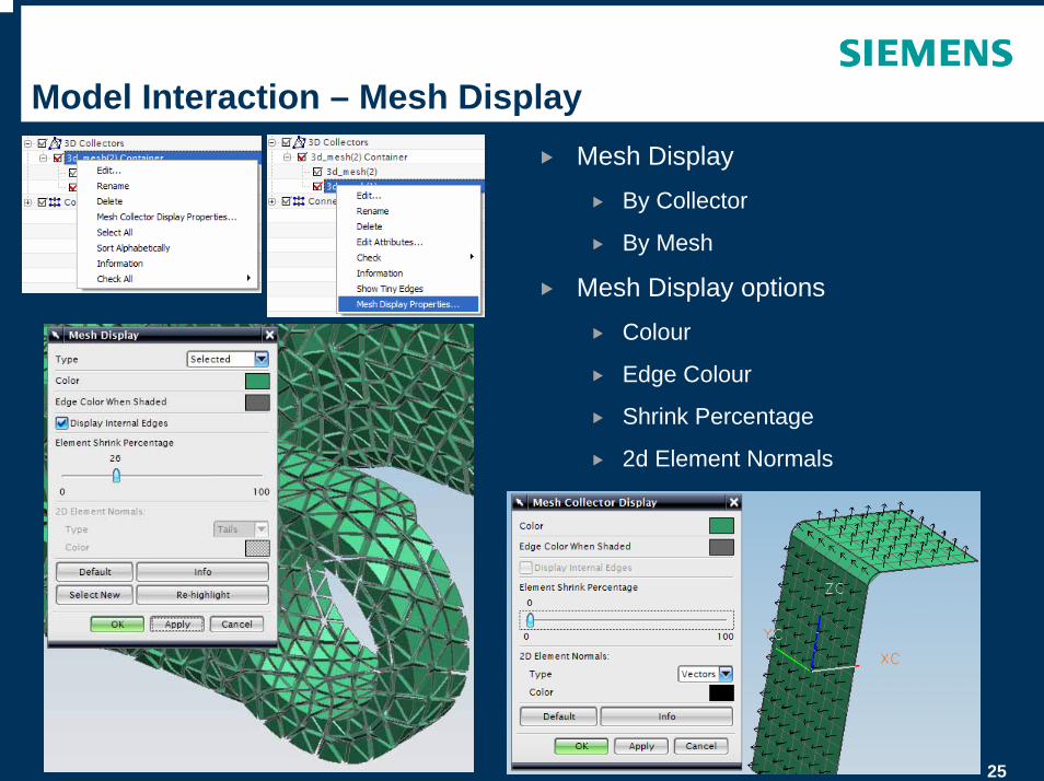
Model Interaction – Mesh DisplayMesh Display
By Collector
By Mesh
Mesh Display optionsColour
Edge Colour
Shrink Percentage
2d Element Normals
26
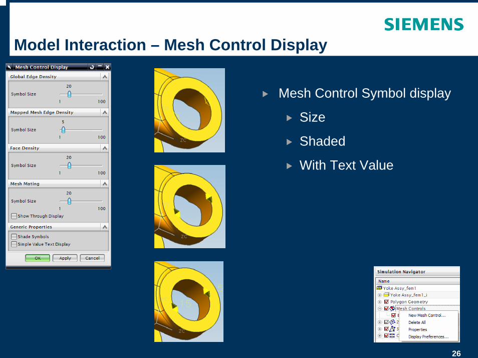
Model Interaction – Mesh Control Display
Mesh Control Symbol display
Size
Shaded
With Text Value
© UGS Corp. 2007. All rights reserved. UGS PLM Software
Solver Language Environment
28
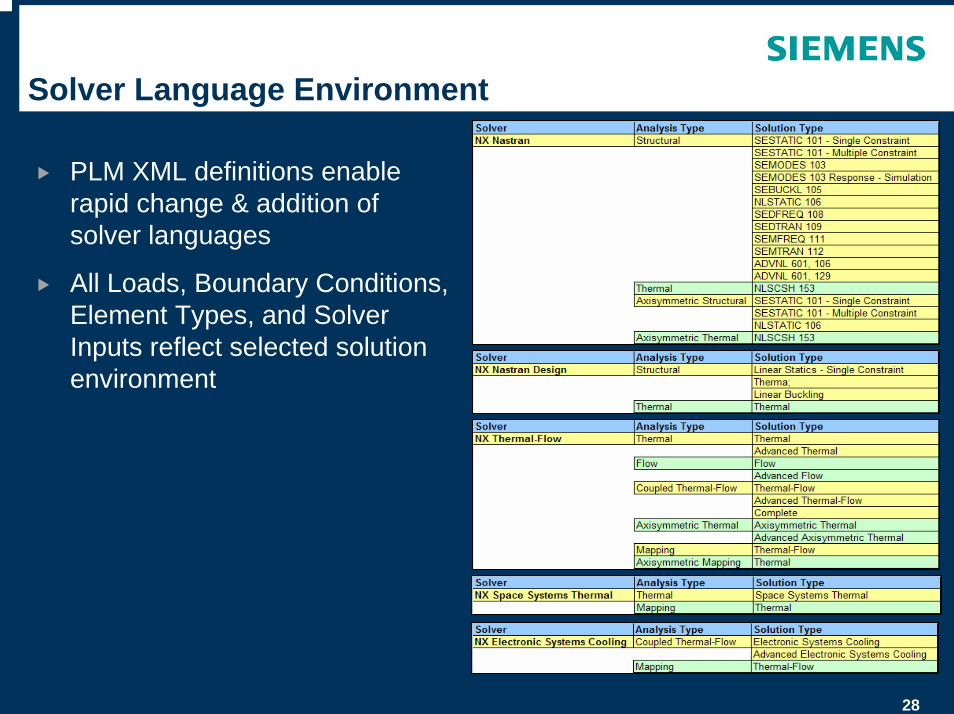
Solver Language Environment
PLM XML definitions enable rapid change & addition of solver languages
All Loads, Boundary Conditions, Element Types, and Solver Inputs reflect selected solution environment
29
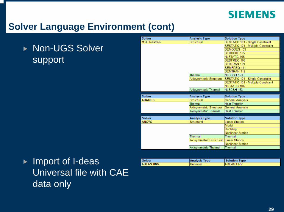
Solver Language Environment (cont)
Non-UGS Solver support
Import of I-deas Universal file with CAE data only
30
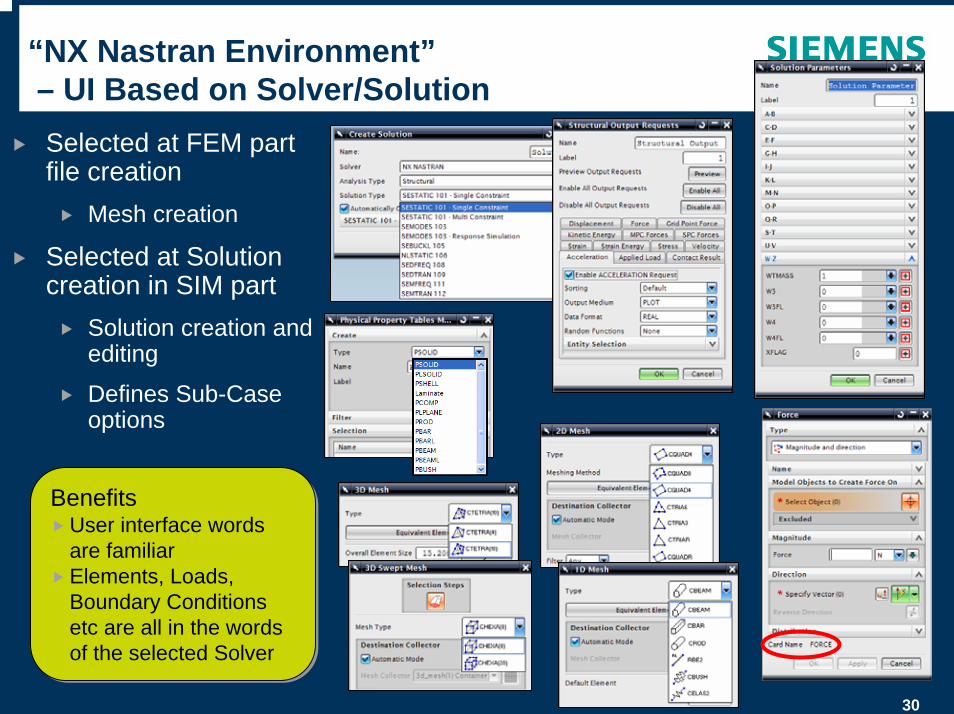
“NX Nastran Environment”– UI Based on Solver/SolutionSelected at FEM part file creation
Mesh creation
Selected at Solution creation in SIM part
Solution creation and editing
Defines Sub-Case options
BenefitsUser interface words are familiarElements, Loads, Boundary Conditions etc are all in the words of the selected Solver
BenefitsUser interface words are familiarElements, Loads, Boundary Conditions etc are all in the words of the selected Solver
31
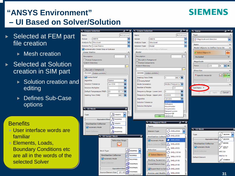
“ANSYS Environment”– UI Based on Solver/Solution
Selected at FEM part file creation
Mesh creation
Selected at Solution creation in SIM part
Solution creation and editing
Defines Sub-Case options
BenefitsUser interface words are familiarElements, Loads, Boundary Conditions etc are all in the words of the selected Solver
BenefitsUser interface words are familiarElements, Loads, Boundary Conditions etc are all in the words of the selected Solver
32
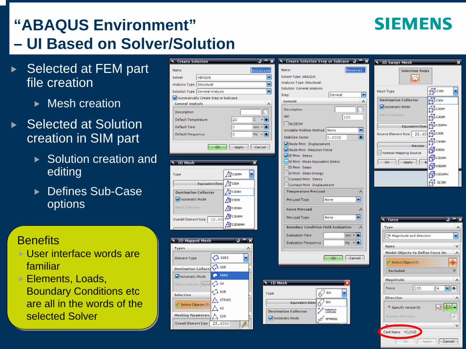
“ABAQUS Environment”– UI Based on Solver/Solution
BenefitsUser interface words are familiarElements, Loads, Boundary Conditions etc are all in the words of the selected Solver
BenefitsUser interface words are familiarElements, Loads, Boundary Conditions etc are all in the words of the selected Solver
Selected at FEM part file creation
Mesh creation
Selected at Solution creation in SIM part
Solution creation and editing
Defines Sub-Case options

© UGS Corp. 2007. All rights reserved. UGS PLM Software
Master Part
34
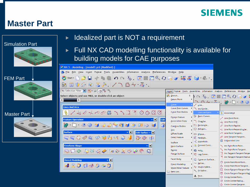
Master PartIdealized part is NOT a requirement
Full NX CAD modelling functionality is available for building models for CAE purposes
FEM Part
Master Part
Simulation Part
35
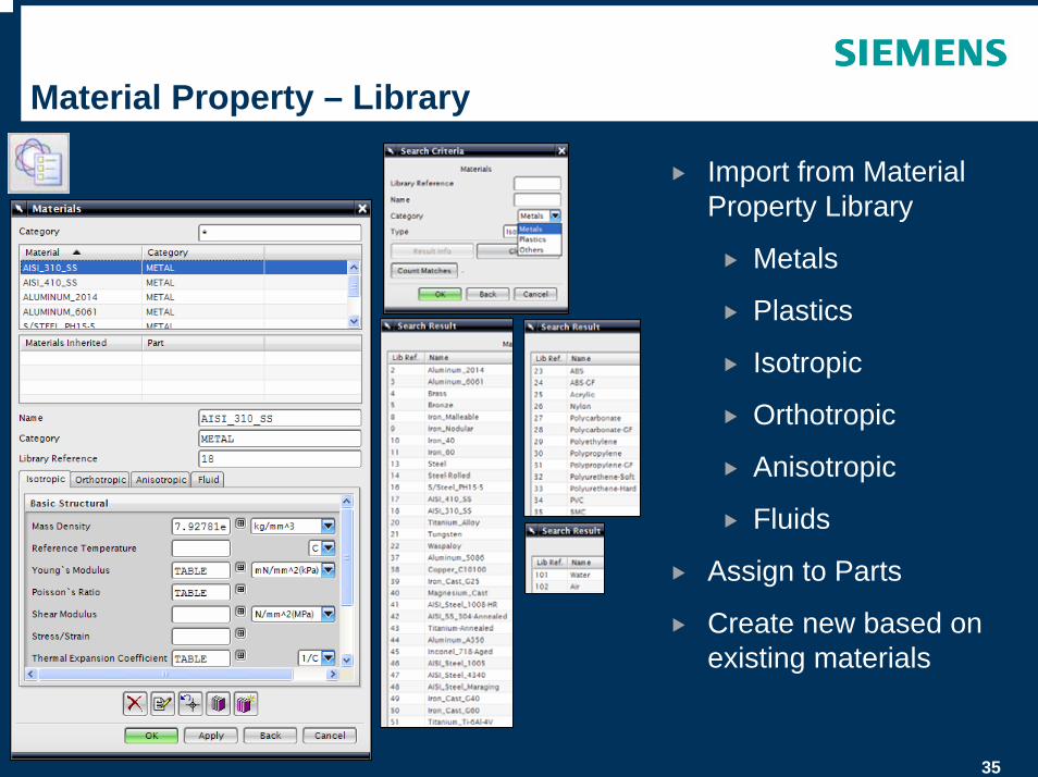
Material Property – Library
Import from Material Property Library
Metals
Plastics
Isotropic
Orthotropic
Anisotropic
Fluids
Assign to Parts
Create new based on existing materials
36
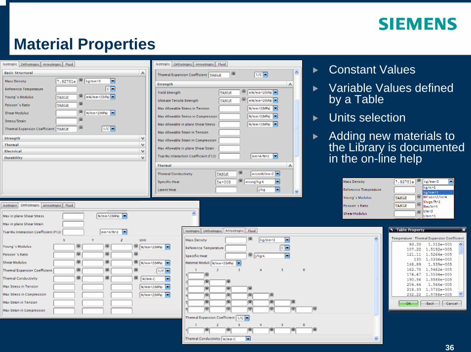
Material PropertiesConstant ValuesVariable Values defined by a TableUnits selectionAdding new materials to the Library is documented in the on-line help
© UGS Corp. 2007. All rights reserved. UGS PLM Software
Idealize Part
38
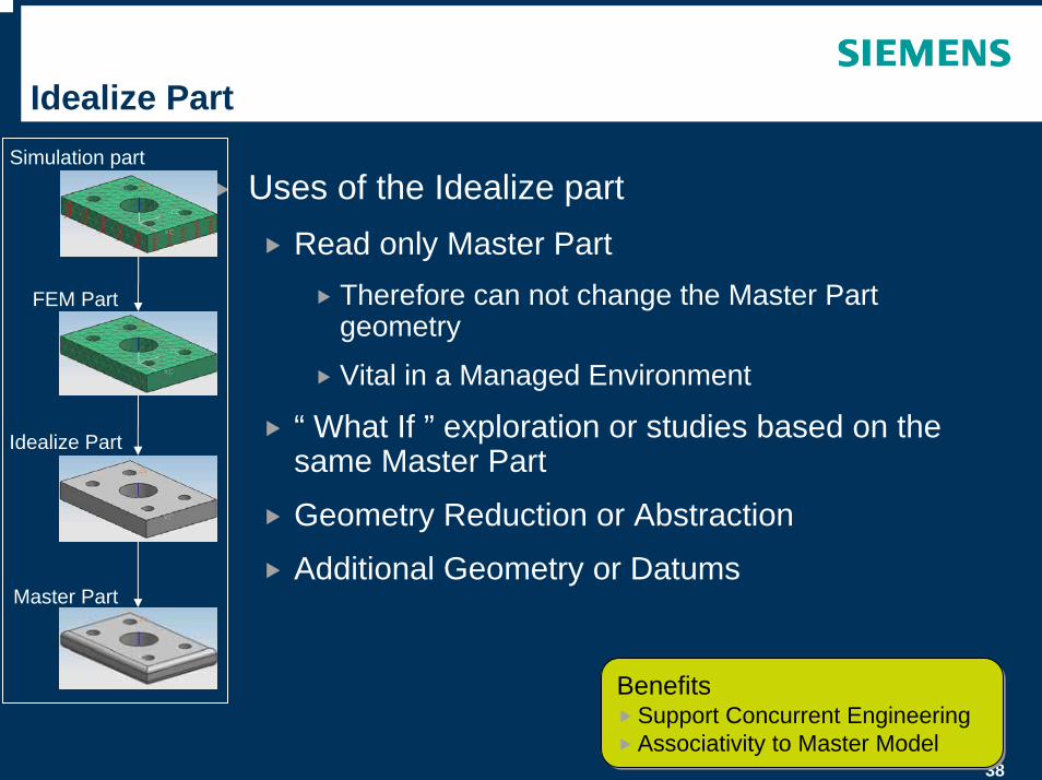
Idealize Part
Uses of the Idealize partRead only Master Part
Therefore can not change the Master Part geometry
Vital in a Managed Environment
“ What If ” exploration or studies based on the same Master Part
Geometry Reduction or Abstraction
Additional Geometry or Datums
Simulation part
FEM Part
Idealize Part
Master Part
BenefitsSupport Concurrent EngineeringAssociativity to Master Model
BenefitsSupport Concurrent EngineeringAssociativity to Master Model
39
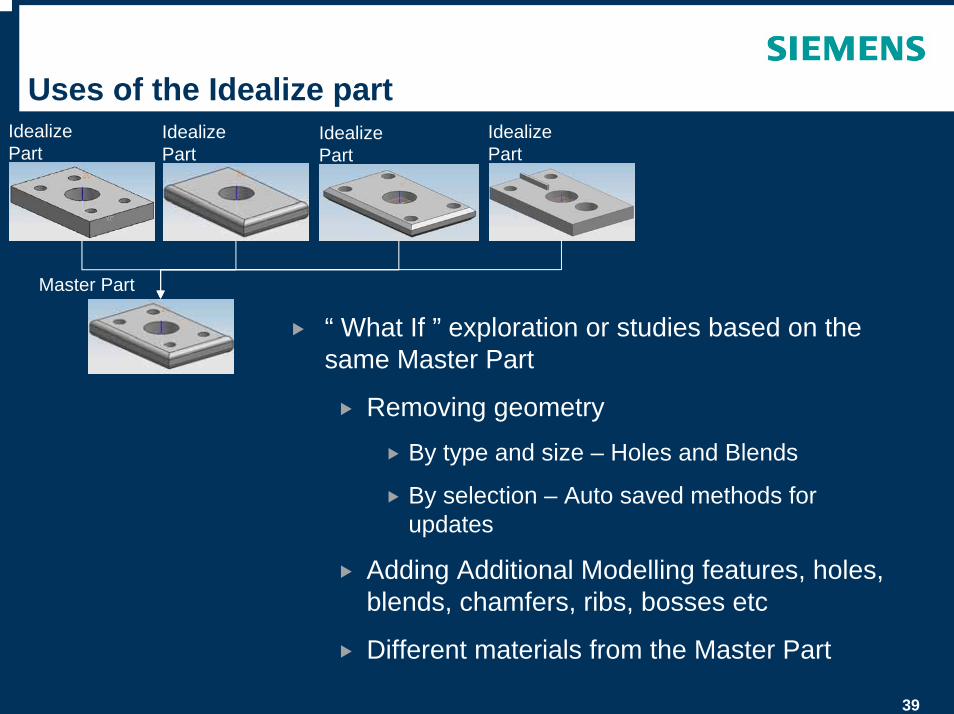
Uses of the Idealize part
“ What If ” exploration or studies based on the same Master Part
Removing geometry
By type and size – Holes and Blends
By selection – Auto saved methods for updates
Adding Additional Modelling features, holes, blends, chamfers, ribs, bosses etc
Different materials from the Master Part
Master Part
Idealize Part
Idealize Part
Idealize Part
Idealize Part
40
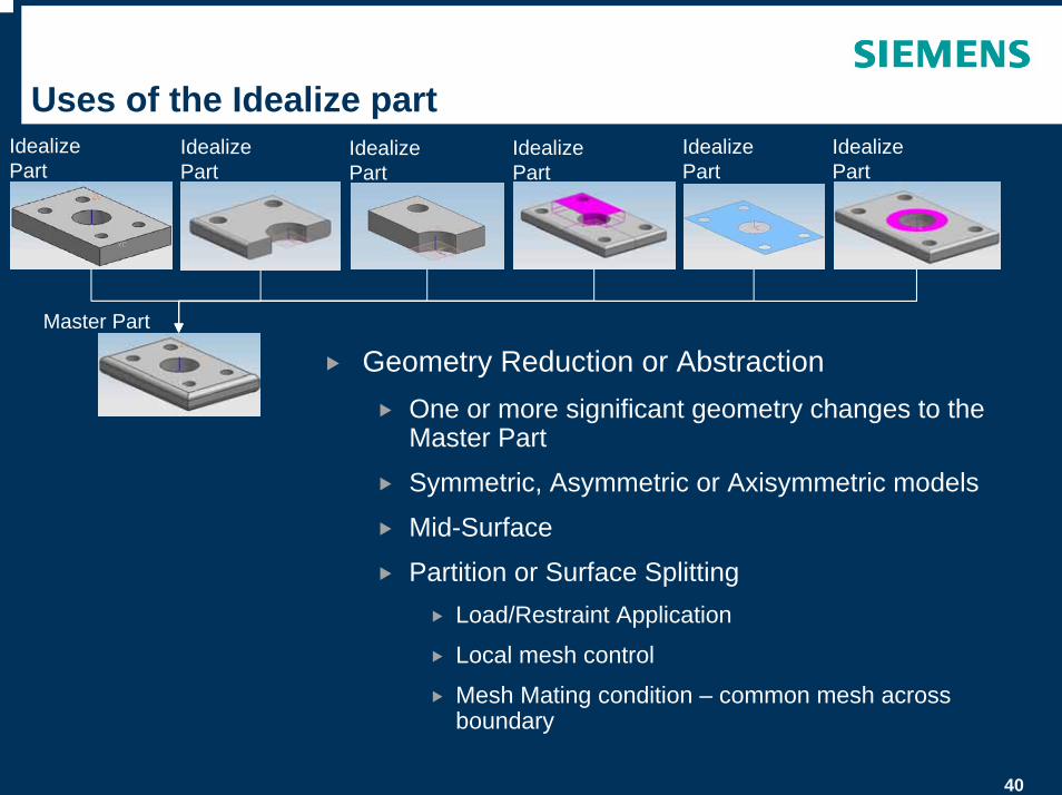
Uses of the Idealize part
Geometry Reduction or AbstractionOne or more significant geometry changes to the Master Part
Symmetric, Asymmetric or Axisymmetric models
Mid-Surface
Partition or Surface Splitting Load/Restraint Application
Local mesh control
Mesh Mating condition – common mesh across boundary
Master Part
Idealize Part
Idealize Part
Idealize Part
Idealize Part
Idealize Part
Idealize Part
41
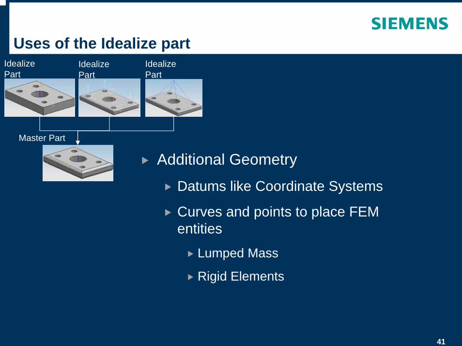
Uses of the Idealize part
Additional Geometry
Datums like Coordinate Systems
Curves and points to place FEM entities
Lumped Mass
Rigid Elements
Master Part
Idealize Part
Idealize Part
Idealize Part
42
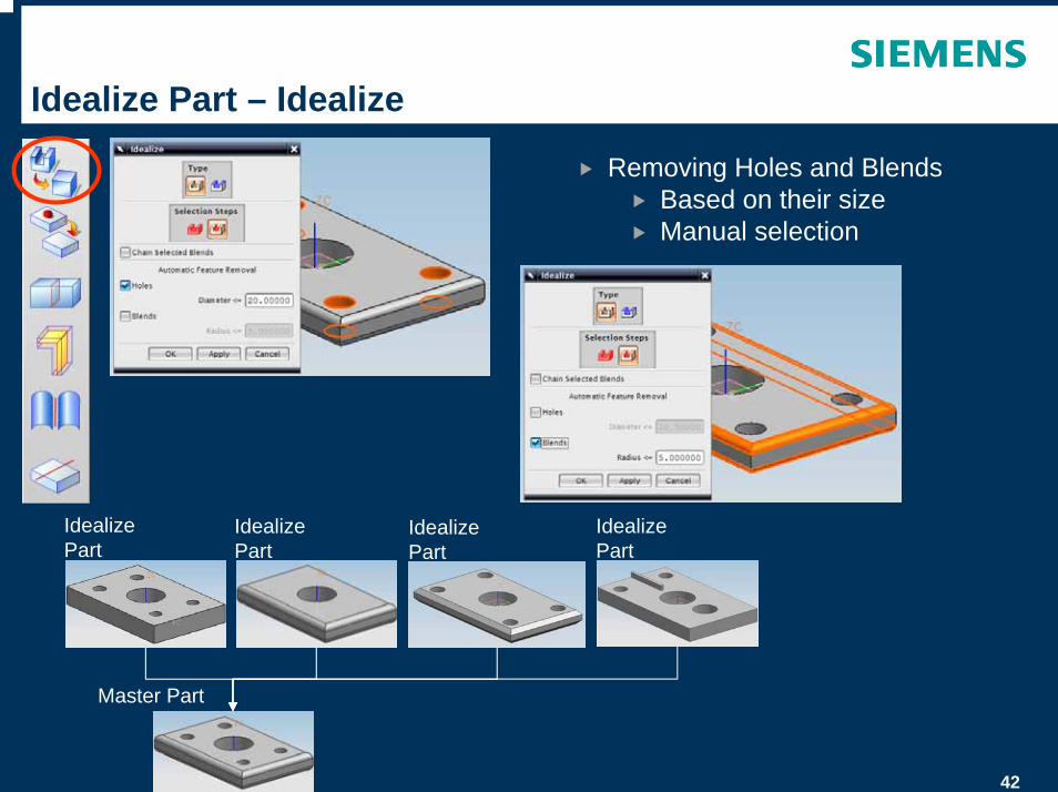
Idealize Part – Idealize
Removing Holes and Blends Based on their sizeManual selection
Master Part
Idealize Part
Idealize Part
Idealize Part
Idealize Part

43
Idealize Part – Defeature Geometry
Master Part
Idealize Part
Idealize Part
Pick outermost face as seed
Pick Region boundary faces
Resulting “De-feature”
Selected faces
Removing Geometry by SelectionMethod saved for Update replays
44
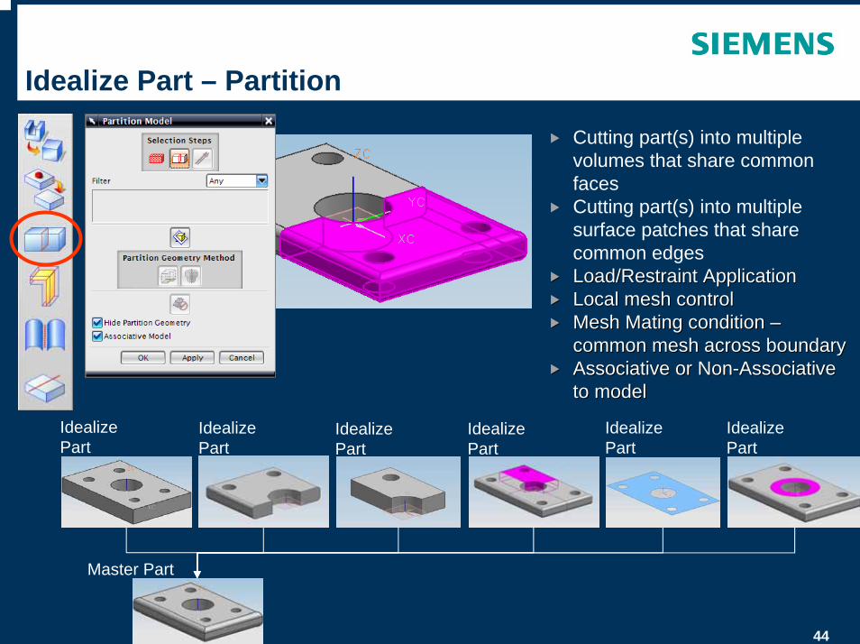
Idealize Part – Partition
Cutting part(s) into multiple volumes that share common facesCutting part(s) into multiple surface patches that share common edgesLoad/Restraint ApplicationLoad/Restraint ApplicationLocal mesh controlLocal mesh controlMesh Mating condition Mesh Mating condition ––common mesh across boundarycommon mesh across boundaryAssociative or NonAssociative or Non--Associative Associative to modelto model
Master Part
Idealize Part
Idealize Part
Idealize Part
Idealize Part
Idealize Part
Idealize Part
45
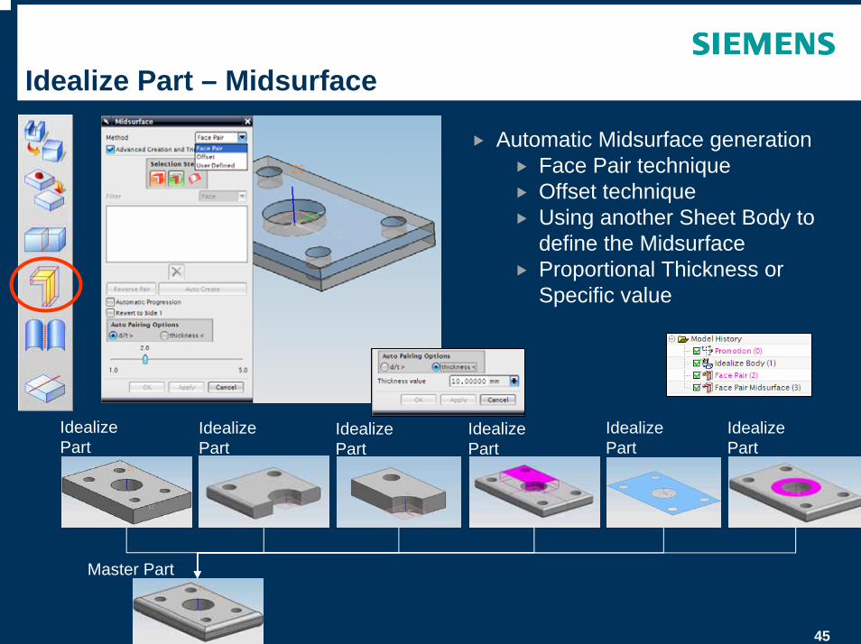
Idealize Part – Midsurface
Automatic Midsurface generationFace Pair techniqueOffset techniqueUsing another Sheet Body to define the MidsurfaceProportional Thickness or Specific value
Master Part
Idealize Part
Idealize Part
Idealize Part
Idealize Part
Idealize Part
Idealize Part
46
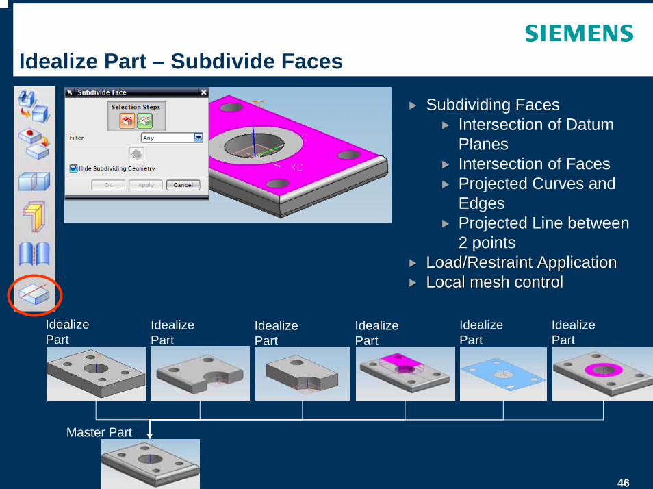
Idealize Part – Subdivide Faces
Subdividing FacesIntersection of Datum PlanesIntersection of FacesProjected Curves and EdgesProjected Line between 2 points
Load/Restraint ApplicationLoad/Restraint ApplicationLocal mesh controlLocal mesh control
Master Part
Idealize Part
Idealize Part
Idealize Part
Idealize Part
Idealize Part
Idealize Part
47
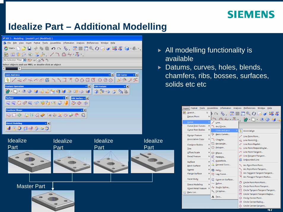
Idealize Part – Additional Modelling
All modelling functionality is availableDatums, curves, holes, blends, chamfers, ribs, bosses, surfaces, solids etc etc
Idealize Part
Master Part
Idealize Part
Idealize Part
Idealize Part
48
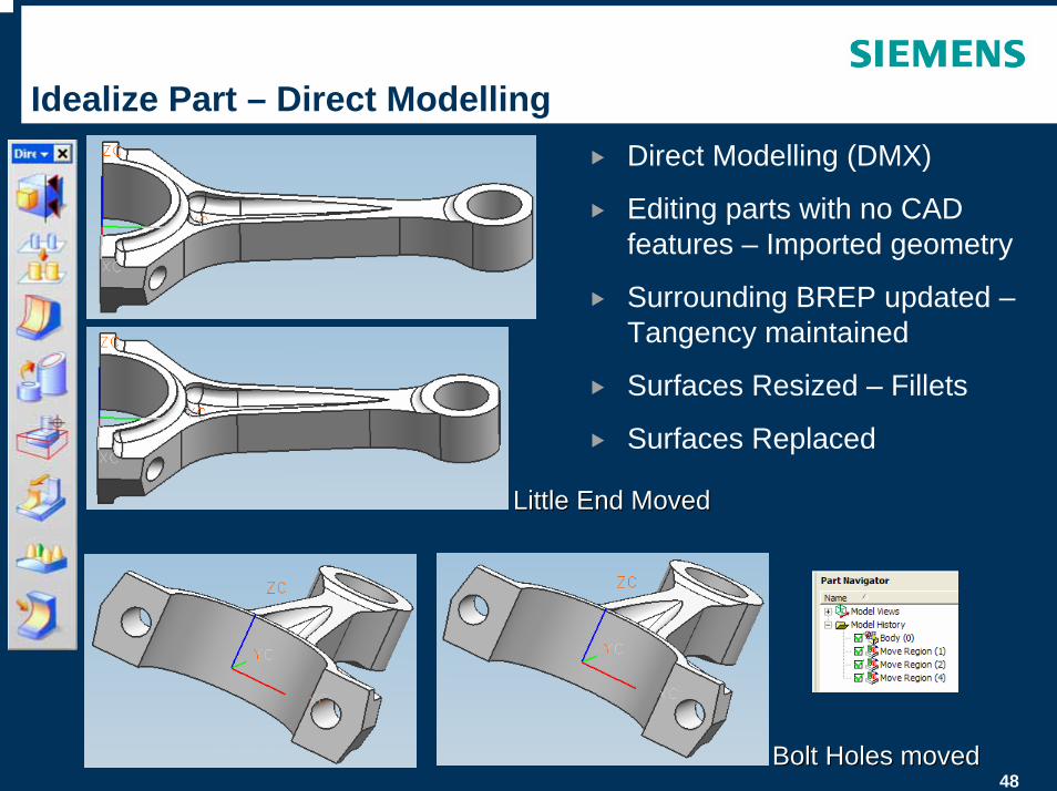
Idealize Part – Direct ModellingDirect Modelling (DMX)
Editing parts with no CAD features – Imported geometry
Surrounding BREP updated –Tangency maintained
Surfaces Resized – Fillets
Surfaces Replaced
Bolt Holes movedBolt Holes moved
Little End MovedLittle End Moved
49
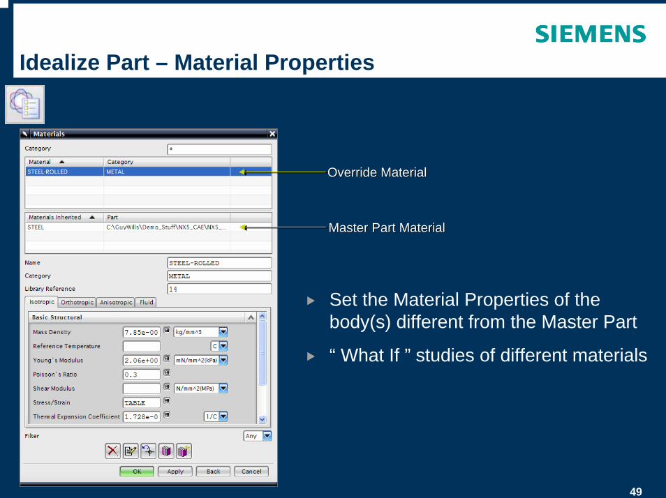
Idealize Part – Material Properties
Set the Material Properties of the body(s) different from the Master Part
“ What If ” studies of different materials
Override MaterialOverride Material
Master Part MaterialMaster Part Material
© UGS Corp. 2007. All rights reserved. UGS PLM Software
FEM Part
51
FEM Part
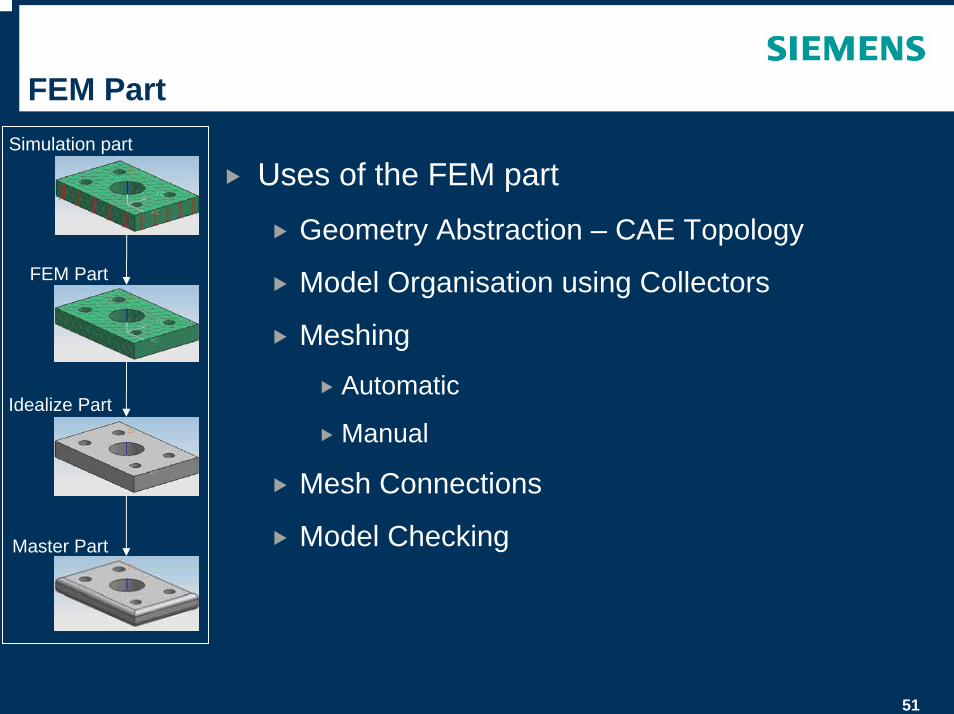
Uses of the FEM part
Geometry Abstraction – CAE Topology
Model Organisation using Collectors
Meshing
Automatic
Manual
Mesh Connections
Model Checking
Simulation part
FEM Part
Idealize Part
Master Part
52
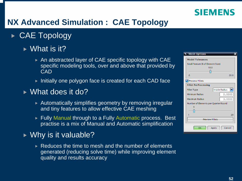
NX Advanced Simulation : CAE TopologyCAE Topology
What is it?An abstracted layer of CAE specific topology with CAE specific modeling tools, over and above that provided by CAD
Initially one polygon face is created for each CAD face
What does it do?Automatically simplifies geometry by removing irregular and tiny features to allow effective CAE meshing
Fully Manual through to a Fully Automatic process. Best practise is a mix of Manual and Automatic simplification
Why is it valuable?Reduces the time to mesh and the number of elements generated (reducing solve time) while improving element quality and results accuracy
53
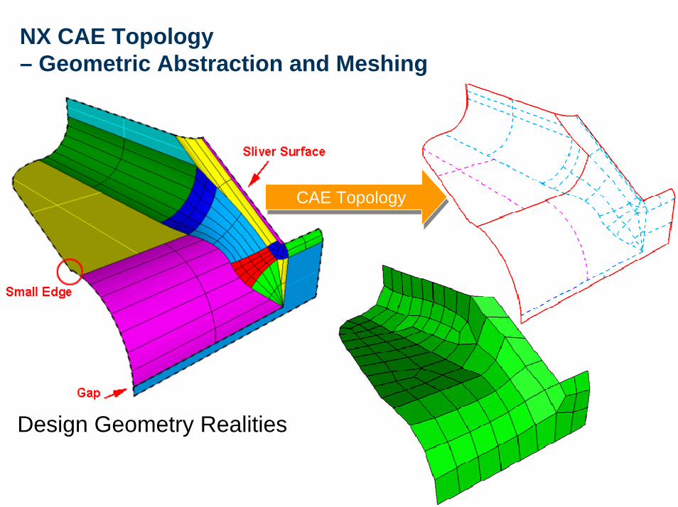
NX CAE Topology– Geometric Abstraction and Meshing
Design Geometry Realities
CAE TopologyCAE Topology
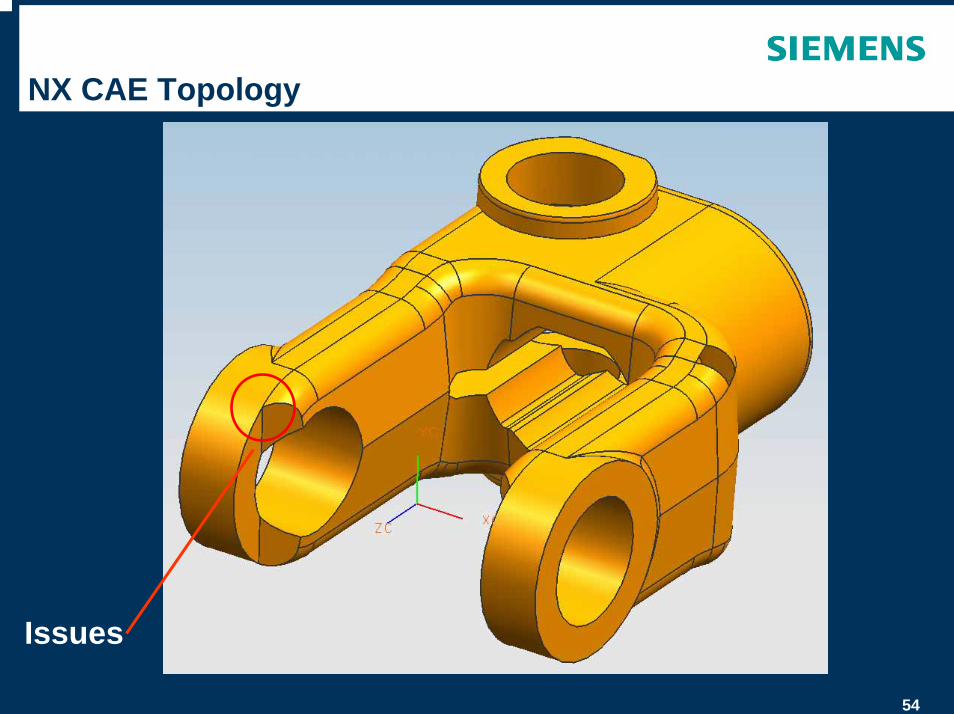
54
Issues
NX CAE Topology
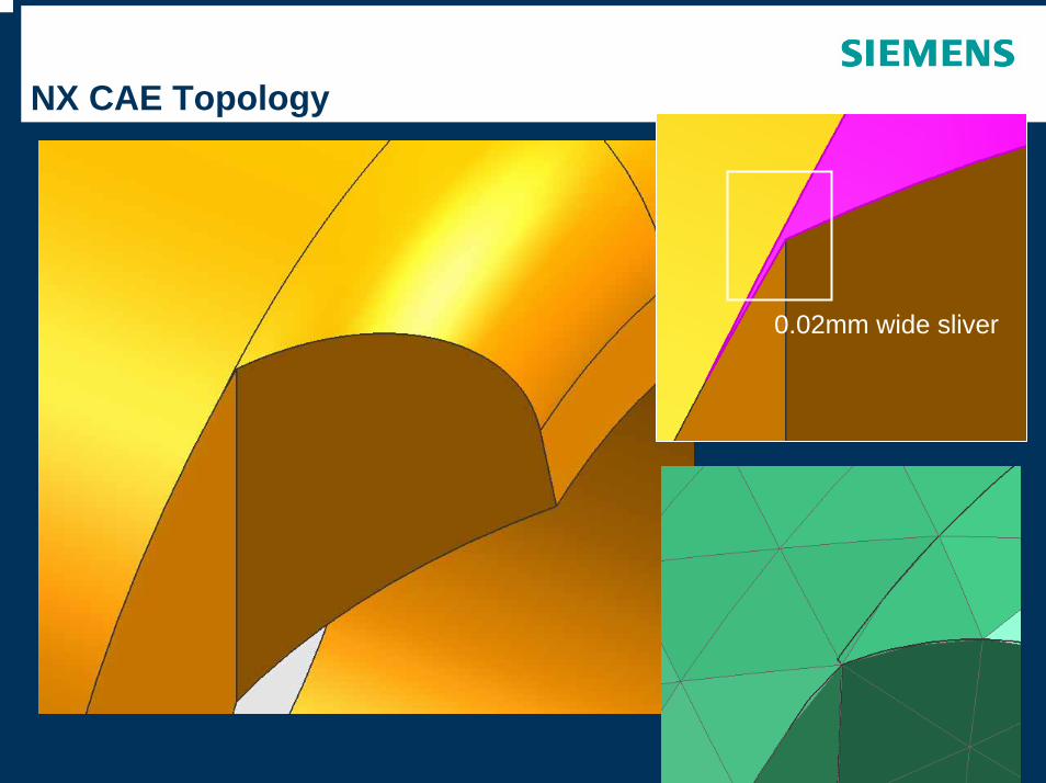
55
NX CAE Topology
0.02mm wide sliver
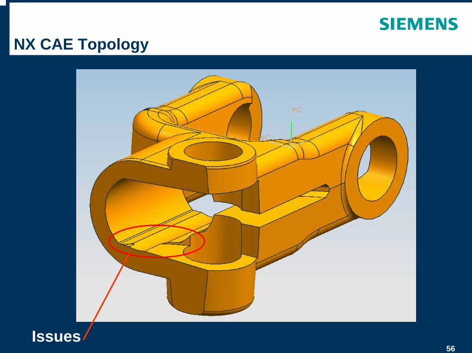
56
NX CAE Topology
Issues
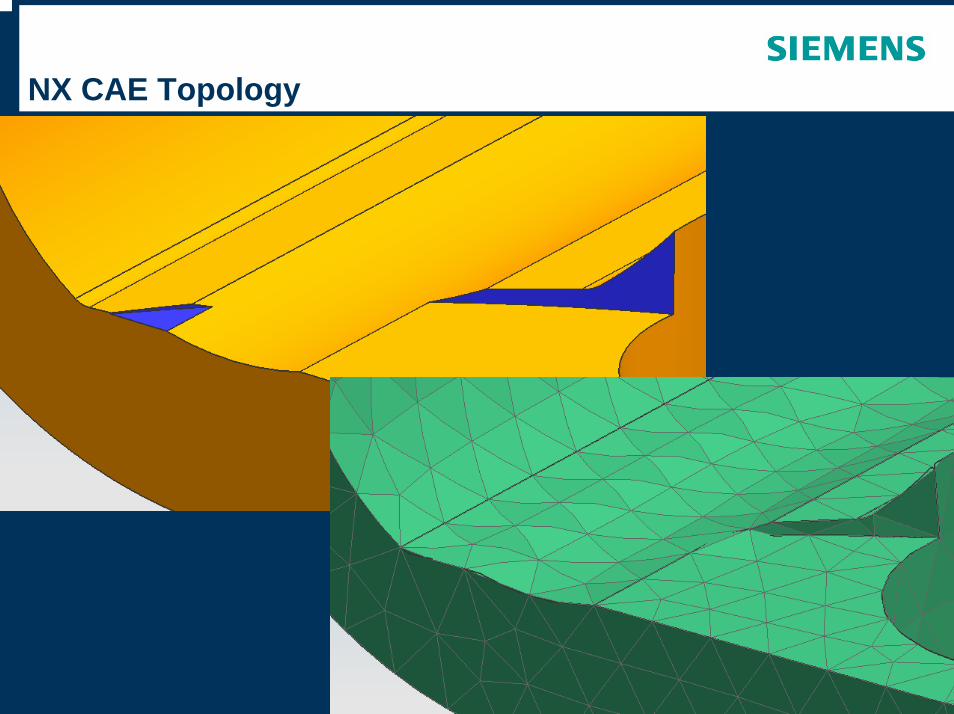
57
NX CAE Topology
58
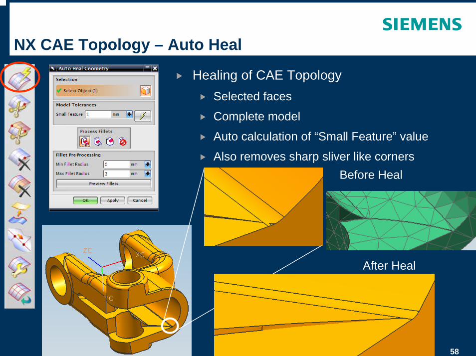
NX CAE Topology – Auto Heal
Healing of CAE TopologySelected faces
Complete model
Auto calculation of “Small Feature” value
Also removes sharp sliver like cornersBefore Heal
After Heal
59
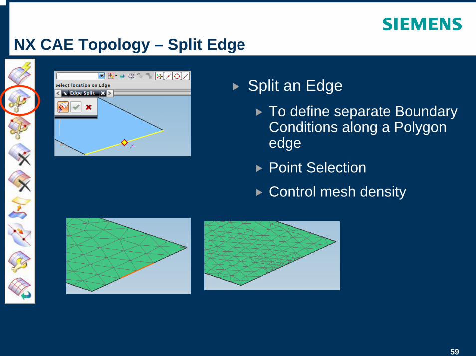
NX CAE Topology – Split Edge
Split an EdgeTo define separate Boundary Conditions along a Polygon edge
Point Selection
Control mesh density
60
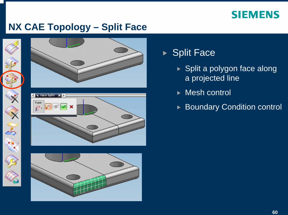
NX CAE Topology – Split Face
Split FaceSplit a polygon face along a projected line
Mesh control
Boundary Condition control
61
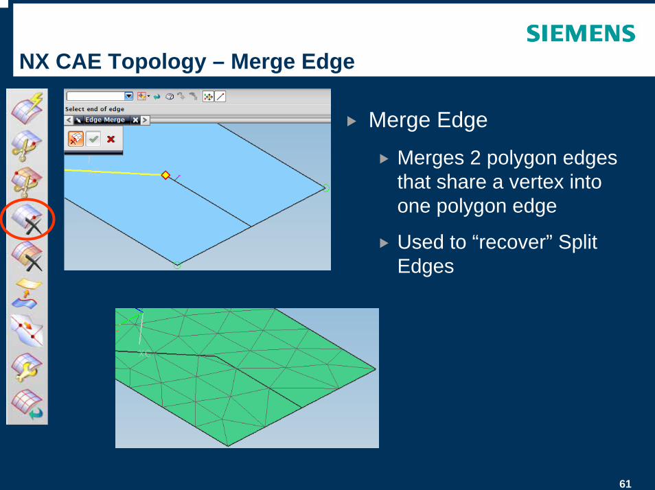
NX CAE Topology – Merge Edge
Merge Edge
Merges 2 polygon edges that share a vertex into one polygon edge
Used to “recover” Split Edges
62
NX CAE Topology – Merge Face
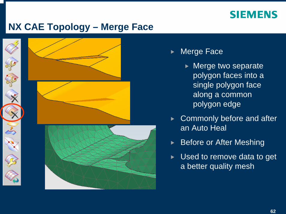
Merge Face
Merge two separate polygon faces into a single polygon face along a common polygon edge
Commonly before and after an Auto Heal
Before or After Meshing
Used to remove data to get a better quality mesh
63
NX CAE Topology – Match Edge
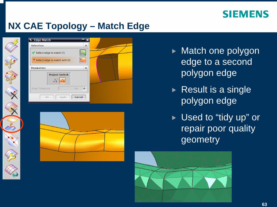
Match one polygon edge to a second polygon edge
Result is a single polygon edge
Used to “tidy up” or repair poor quality geometry
64
NX CAE Topology – Collapse Edge
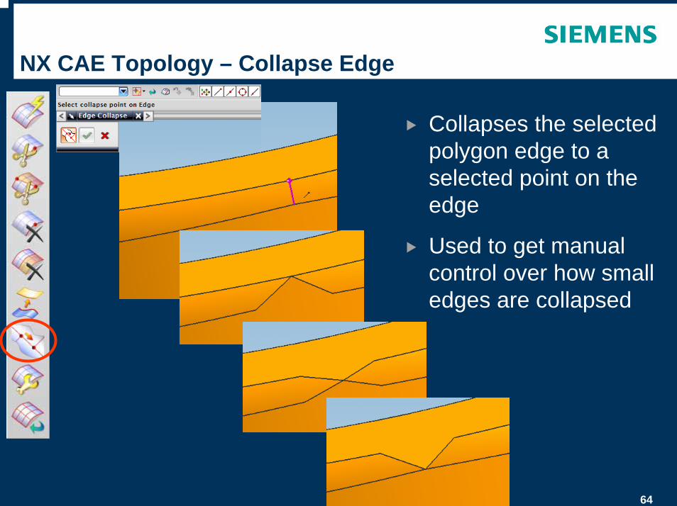
Collapses the selected polygon edge to a selected point on the edge
Used to get manual control over how small edges are collapsed
65
NX CAE Topology – Face Repair
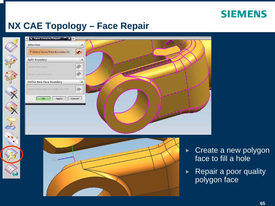
Create a new polygon face to fill a hole
Repair a poor quality polygon face
66
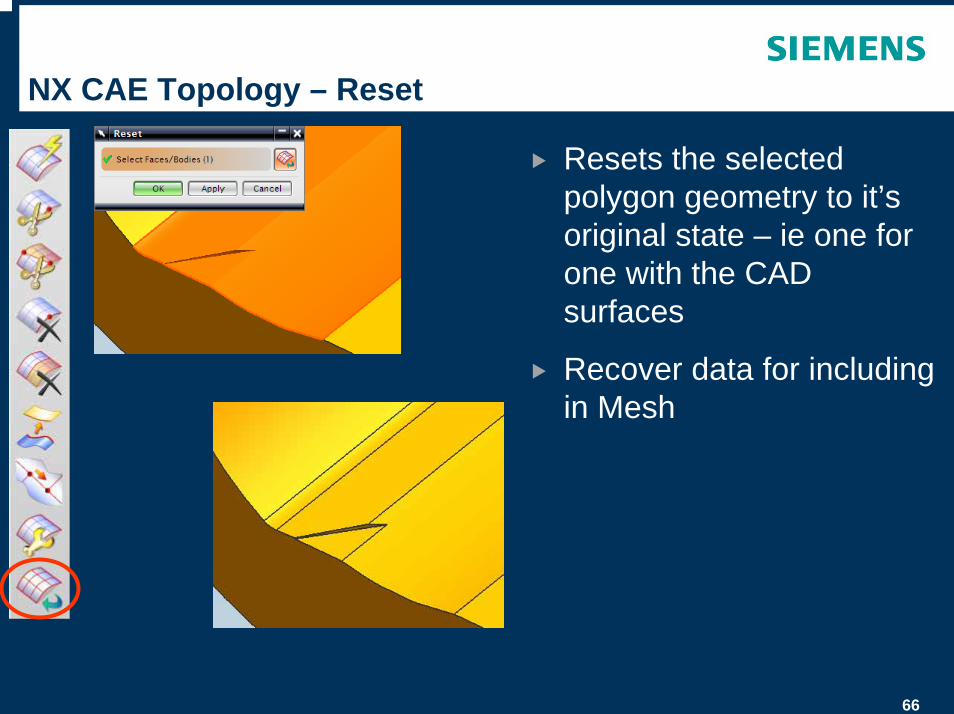
NX CAE Topology – Reset
Resets the selected polygon geometry to it’s original state – ie one for one with the CAD surfaces
Recover data for including in Mesh
67
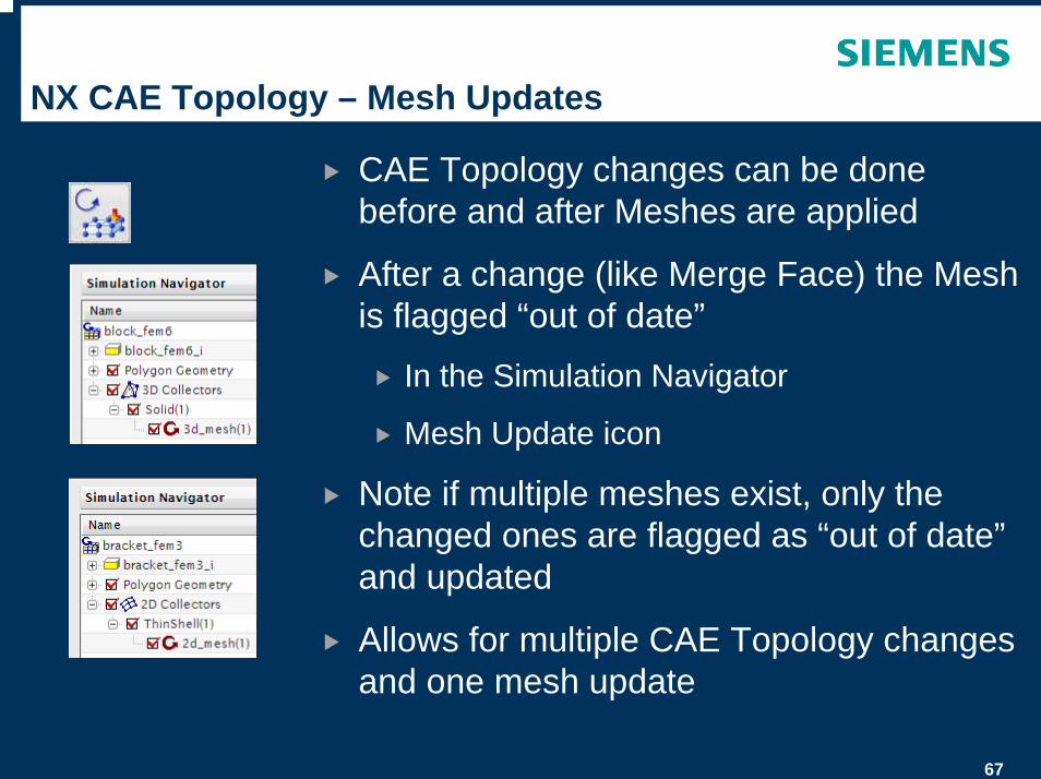
NX CAE Topology – Mesh Updates
CAE Topology changes can be done before and after Meshes are applied
After a change (like Merge Face) the Mesh is flagged “out of date”
In the Simulation Navigator
Mesh Update icon
Note if multiple meshes exist, only the changed ones are flagged as “out of date”and updated
Allows for multiple CAE Topology changes and one mesh update
68
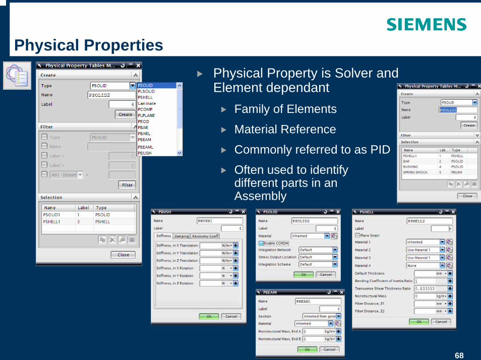
Physical PropertiesPhysical Property is Solver and Element dependant
Family of Elements
Material Reference
Commonly referred to as PID
Often used to identify different parts in an Assembly
69
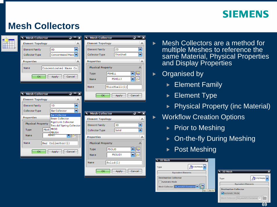
Mesh Collectors
Mesh Collectors are a method for multiple Meshes to reference the same Material, Physical Properties and Display PropertiesOrganised by
Element FamilyElement TypePhysical Property (inc Material)
Workflow Creation OptionsPrior to MeshingOn-the-fly During MeshingPost Meshing
70
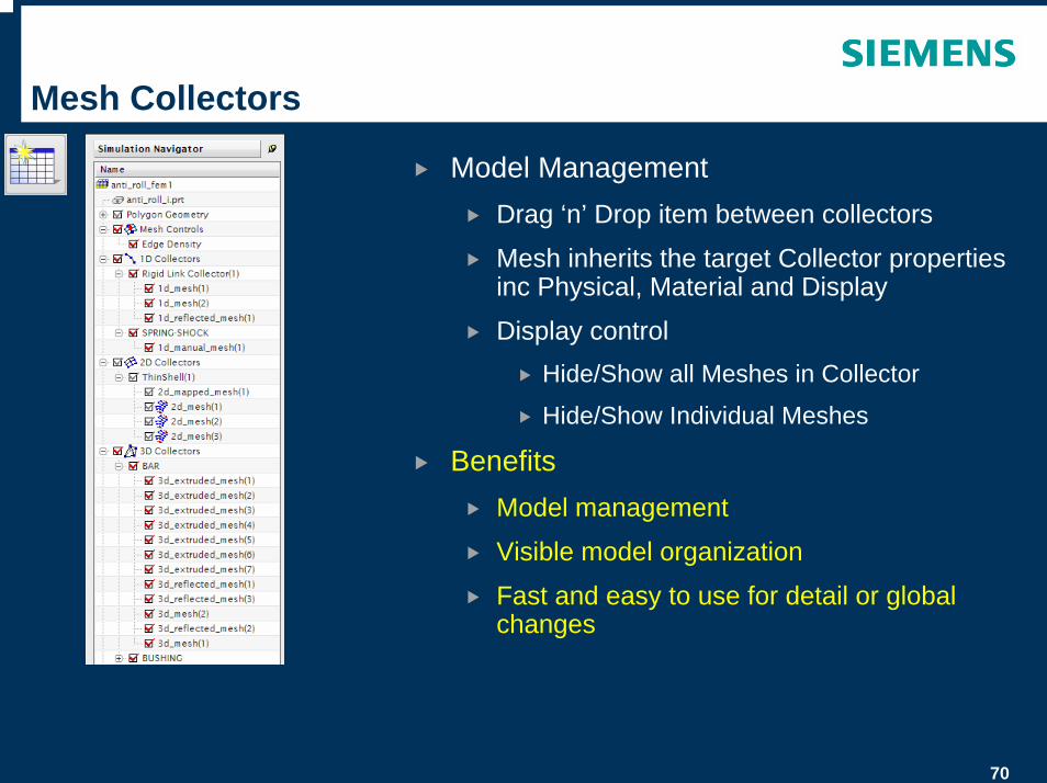
Mesh Collectors
Model ManagementDrag ‘n’ Drop item between collectors
Mesh inherits the target Collector properties inc Physical, Material and Display
Display controlHide/Show all Meshes in Collector
Hide/Show Individual Meshes
BenefitsModel management
Visible model organization
Fast and easy to use for detail or global changes
71
Node and Element Sets
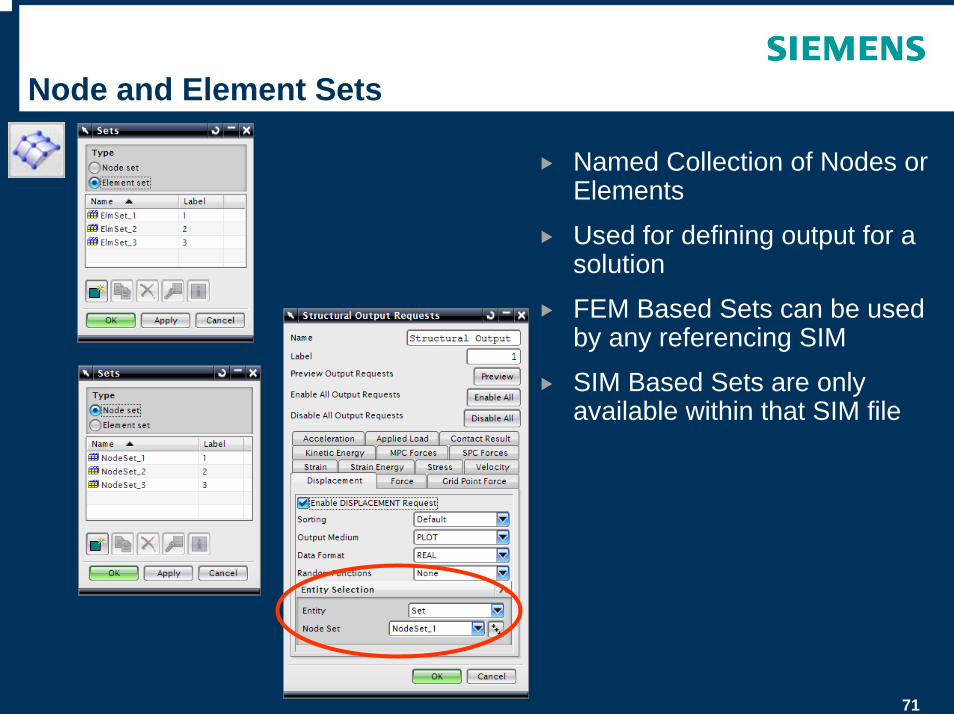
Named Collection of Nodes or Elements
Used for defining output for a solution
FEM Based Sets can be used by any referencing SIM
SIM Based Sets are only available within that SIM file
72
Mesh Append
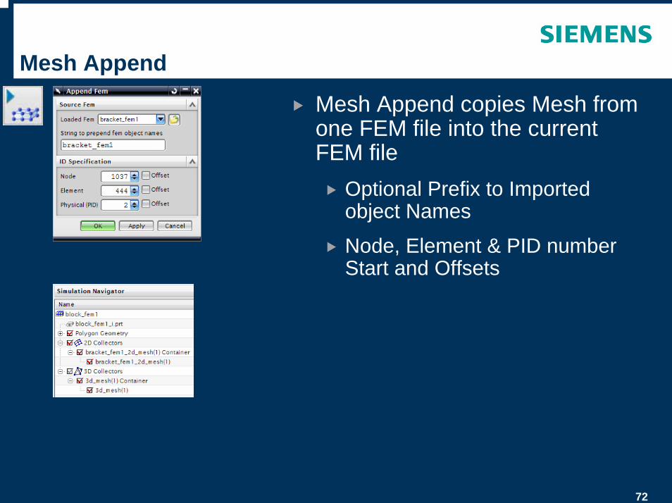
Mesh Append copies Mesh from one FEM file into the current FEM file
Optional Prefix to Imported object Names
Node, Element & PID number Start and Offsets
73
Mesh Import
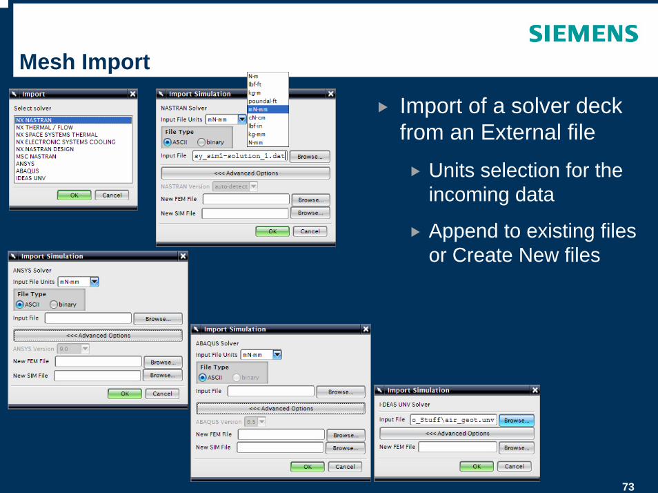
Import of a solver deck from an External file
Units selection for the incoming data
Append to existing files or Create New files
74
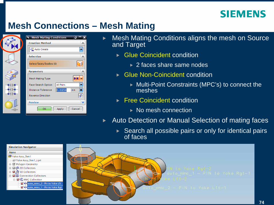
Mesh Connections – Mesh Mating Mesh Mating Conditions aligns the mesh on Source and Target
Glue Coincident condition2 faces share same nodes
Glue Non-Coincident conditionMulti-Point Constraints (MPC’s) to connect the meshes
Free Coincident conditionNo mesh connection
Auto Detection or Manual Selection of mating facesSearch all possible pairs or only for identical pairs of faces
Used to prepare mesh for Contact definition
75
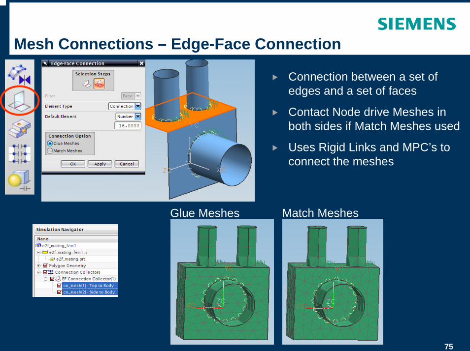
Mesh Connections – Edge-Face Connection
Connection between a set of edges and a set of faces
Contact Node drive Meshes in both sides if Match Meshes used
Uses Rigid Links and MPC’s to connect the meshes
Match MeshesGlue Meshes
76
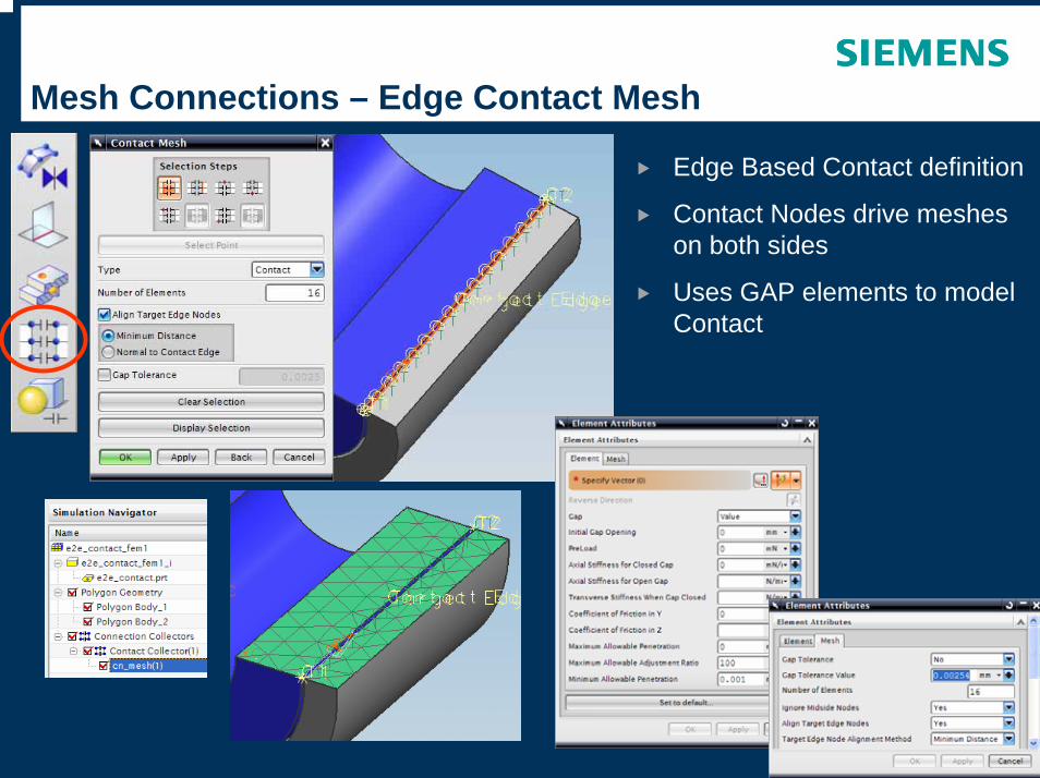
Mesh Connections – Edge Contact Mesh
Edge Based Contact definition
Contact Nodes drive meshes on both sides
Uses GAP elements to model Contact
77
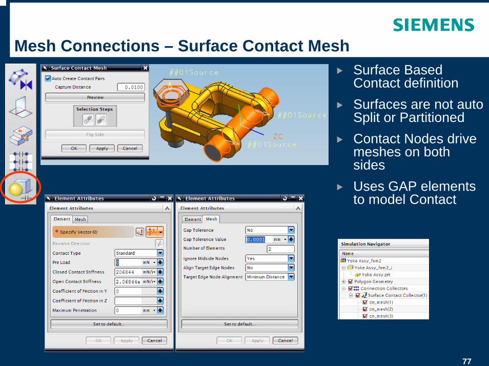
Mesh Connections – Surface Contact MeshSurface Based Contact definitionSurfaces are not auto Split or PartitionedContact Nodes drive meshes on both sidesUses GAP elements to model Contact
78
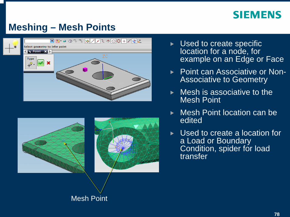
Meshing – Mesh PointsUsed to create specific location for a node, for example on an Edge or FacePoint can Associative or Non-Associative to GeometryMesh is associative to the Mesh PointMesh Point location can be editedUsed to create a location for a Load or Boundary Condition, spider for load transfer
Mesh Point
79
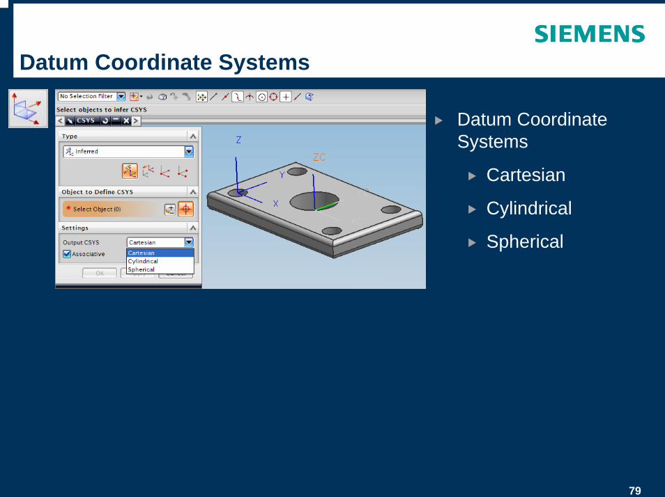
Datum Coordinate Systems
Datum Coordinate Systems
Cartesian
Cylindrical
Spherical
80
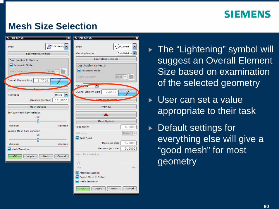
Mesh Size Selection
The “Lightening” symbol will suggest an Overall Element Size based on examination of the selected geometry
User can set a value appropriate to their task
Default settings for everything else will give a “good mesh” for most geometry
81
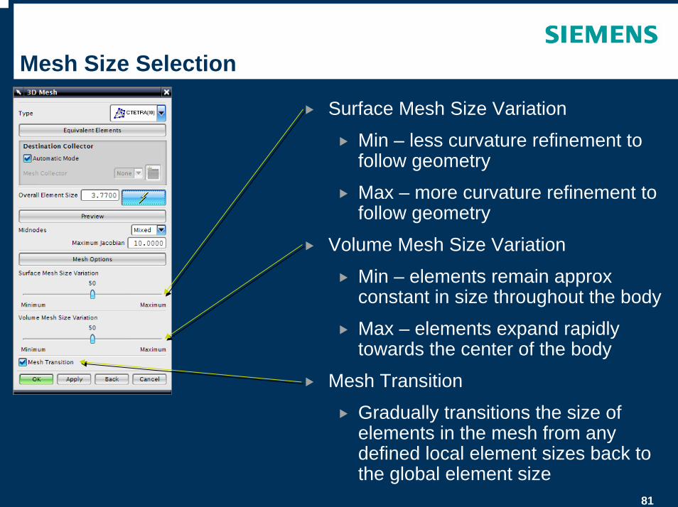
Mesh Size Selection
Surface Mesh Size Variation
Min – less curvature refinement to follow geometry
Max – more curvature refinement to follow geometry
Volume Mesh Size Variation
Min – elements remain approx constant in size throughout the body
Max – elements expand rapidly towards the center of the body
Mesh Transition
Gradually transitions the size of elements in the mesh from any defined local element sizes back to the global element size
82
Mesh Size Selection
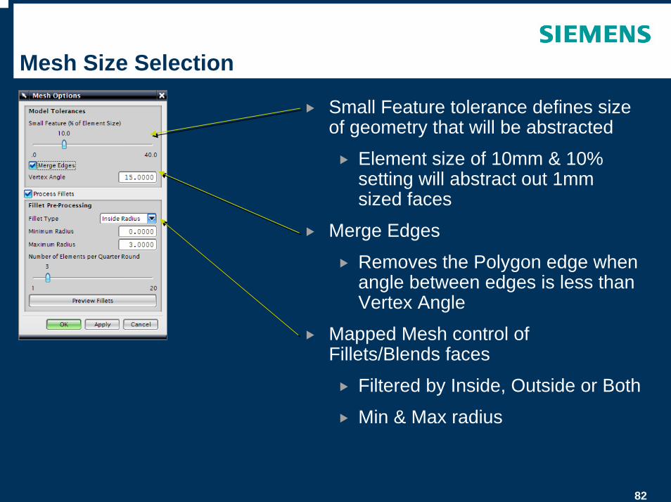
Small Feature tolerance defines size of geometry that will be abstracted
Element size of 10mm & 10% setting will abstract out 1mm sized faces
Merge Edges
Removes the Polygon edge when angle between edges is less than Vertex Angle
Mapped Mesh control of Fillets/Blends faces
Filtered by Inside, Outside or Both
Min & Max radius
83
Mesh Controls
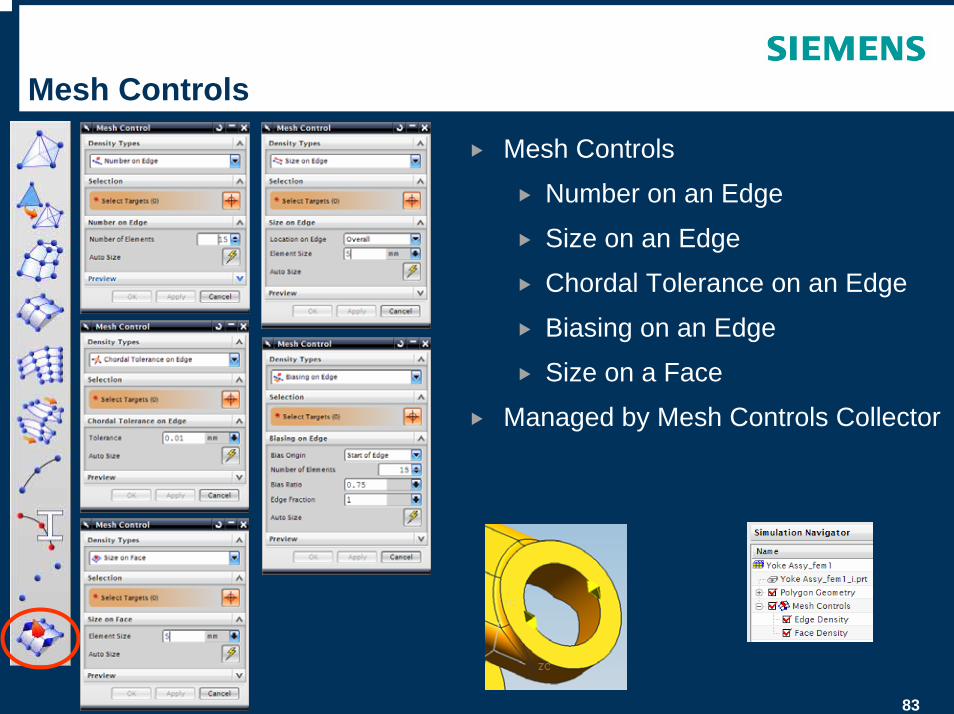
Mesh Controls
Number on an Edge
Size on an Edge
Chordal Tolerance on an Edge
Biasing on an Edge
Size on a Face
Managed by Mesh Controls Collector
84
Mesh Controls
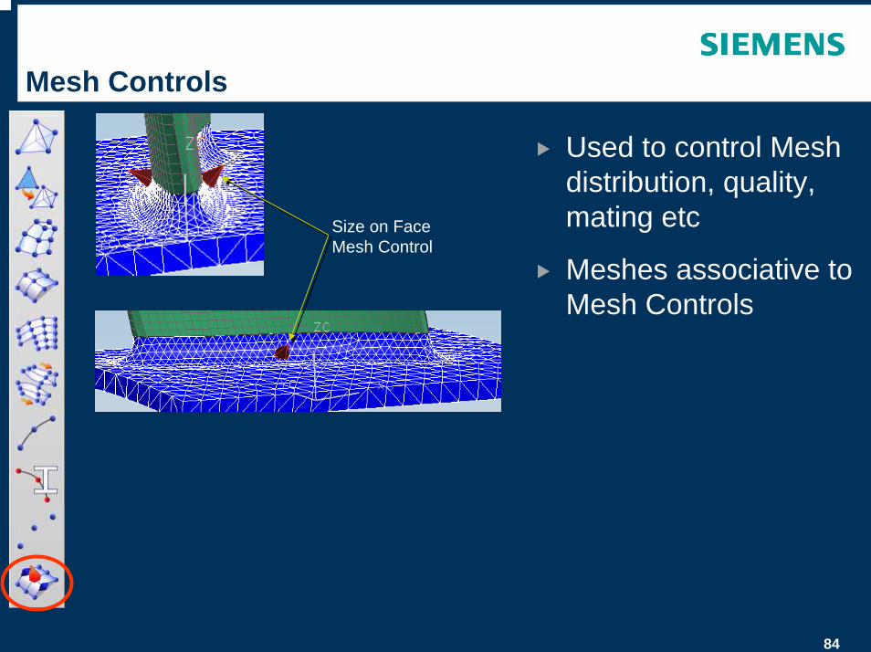
Used to control Mesh distribution, quality, mating etc
Meshes associative to Mesh Controls
Size on Face Mesh Control
85
Meshing – OD Mesh
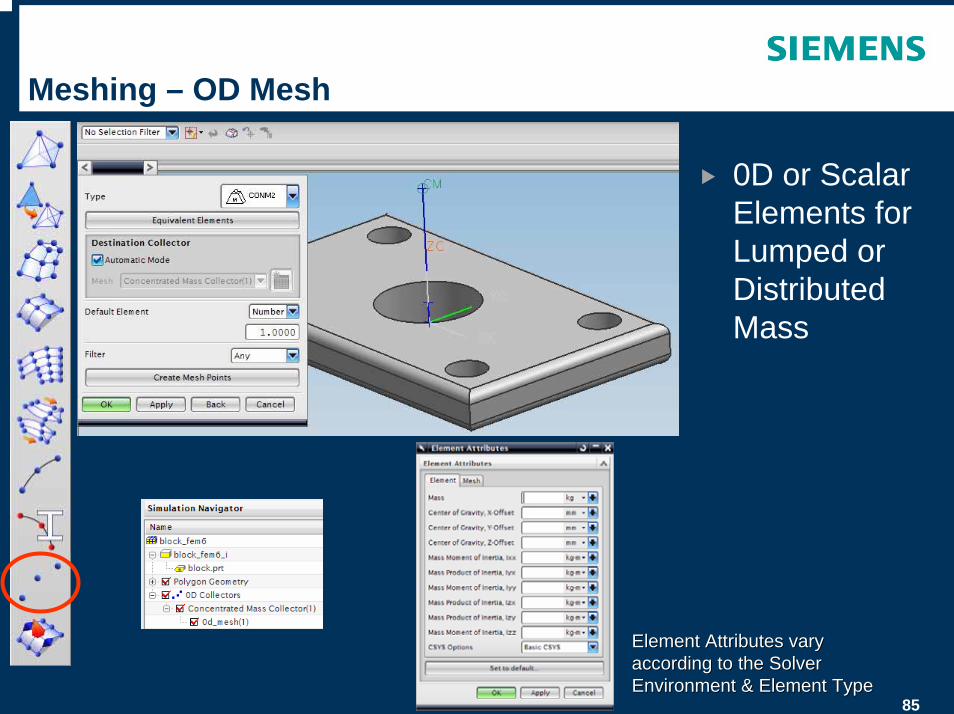
0D or Scalar Elements for Lumped or Distributed Mass
Element Attributes vary Element Attributes vary according to the Solver according to the Solver Environment & Element TypeEnvironment & Element Type
86
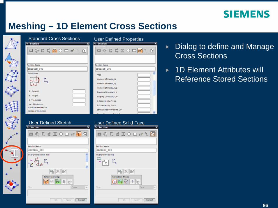
Meshing – 1D Element Cross Sections
Dialog to define and Manage Cross Sections
1D Element Attributes will Reference Stored Sections
Standard Cross Sections User Defined Properties
User Defined Solid FaceUser Defined Sketch
87
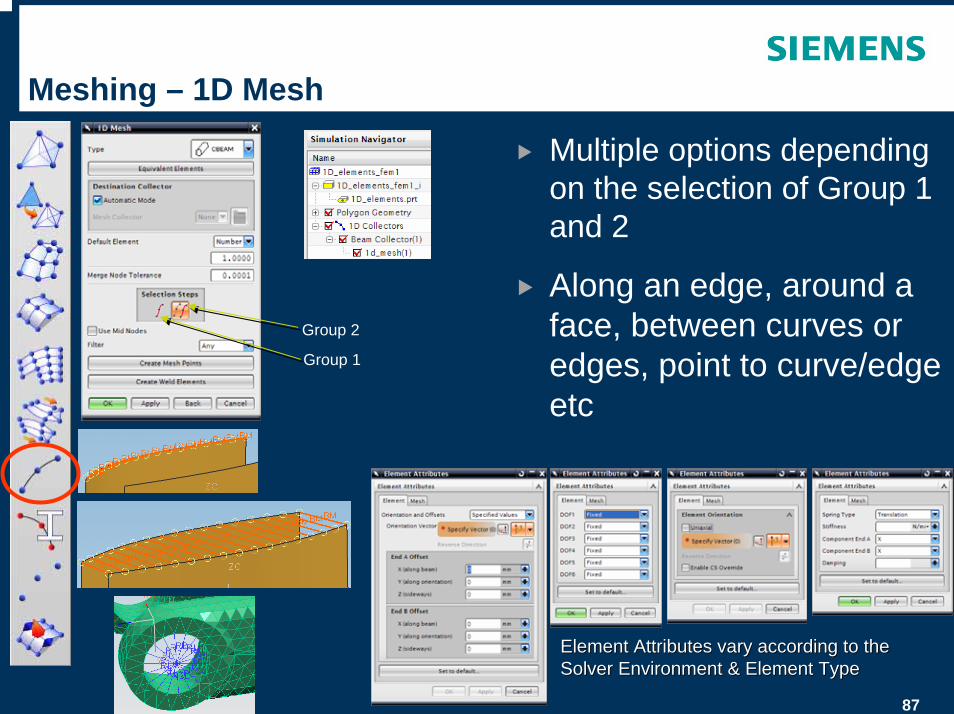
Meshing – 1D Mesh
Multiple options depending on the selection of Group 1 and 2
Along an edge, around a face, between curves or edges, point to curve/edge etc
Group 1
Group 2
Element Attributes vary according to the Element Attributes vary according to the Solver Environment & Element TypeSolver Environment & Element Type
88
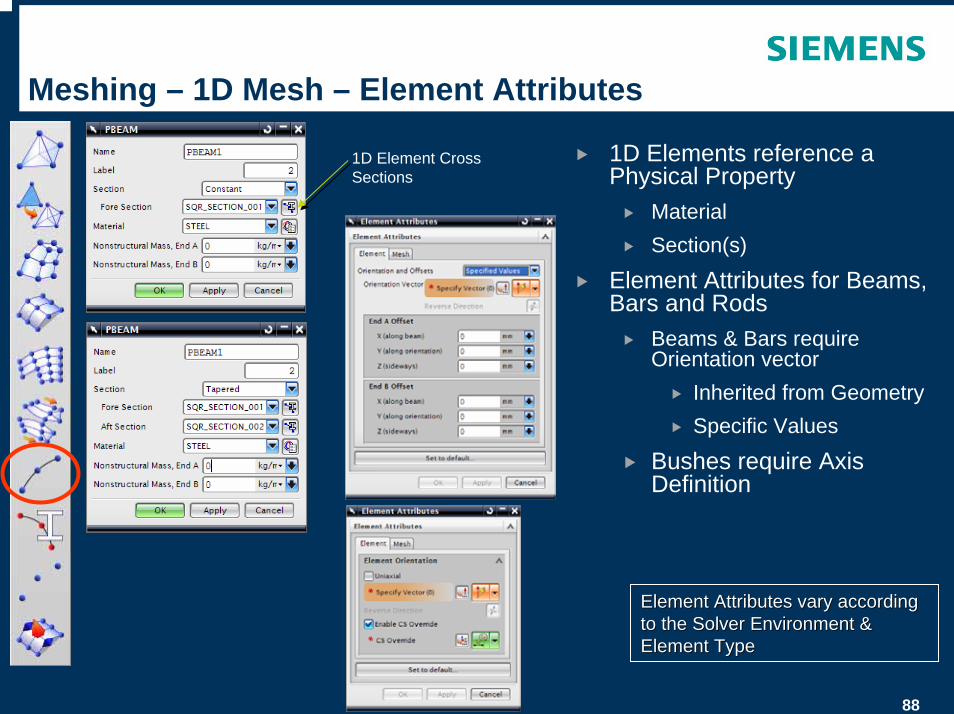
Meshing – 1D Mesh – Element Attributes
1D Elements reference a Physical Property
MaterialSection(s)
Element Attributes for Beams, Bars and Rods
Beams & Bars require Orientation vector
Inherited from GeometrySpecific Values
Bushes require Axis Definition
1D Element Cross Sections
Element Attributes vary according Element Attributes vary according to the Solver Environment & to the Solver Environment & Element TypeElement Type
89
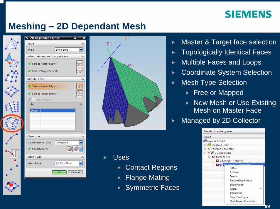
Meshing – 2D Dependant MeshMaster & Target face selectionTopologically Identical FacesMultiple Faces and LoopsCoordinate System SelectionMesh Type Selection
Free or MappedNew Mesh or Use Existing Mesh on Master Face
Managed by 2D Collector
UsesUsesContact RegionsContact RegionsFlange MatingFlange MatingSymmetric FacesSymmetric Faces
90
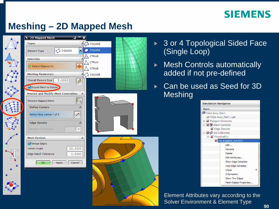
Meshing – 2D Mapped Mesh
3 or 4 Topological Sided Face (Single Loop)
Mesh Controls automatically added if not pre-defined
Can be used as Seed for 3D Meshing
Element Attributes vary according to the Element Attributes vary according to the Solver Environment & Element TypeSolver Environment & Element Type
91
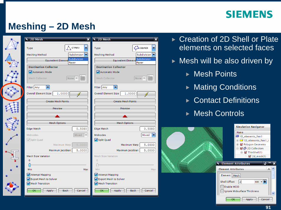
Meshing – 2D MeshCreation of 2D Shell or Plate elements on selected faces
Mesh will be also driven by
Mesh Points
Mating Conditions
Contact Definitions
Mesh Controls
92
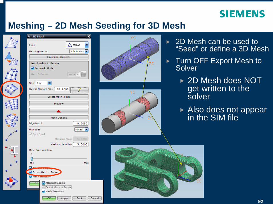
Meshing – 2D Mesh Seeding for 3D Mesh2D Mesh can be used to “Seed” or define a 3D MeshTurn OFF Export Mesh to Solver
2D Mesh does NOT get written to the solverAlso does not appear in the SIM file
93
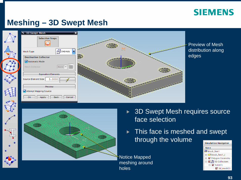
Meshing – 3D Swept Mesh
3D Swept Mesh requires source face selection
This face is meshed and swept through the volume
Preview of Mesh distribution along edges
Notice Mapped meshing around holes
94
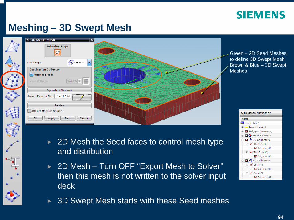
Meshing – 3D Swept Mesh
2D Mesh the Seed faces to control mesh type and distribution
2D Mesh – Turn OFF “Export Mesh to Solver”then this mesh is not written to the solver input deck
3D Swept Mesh starts with these Seed meshes
Green – 2D Seed Meshes to define 3D Swept MeshBrown & Blue – 3D Swept Meshes
95
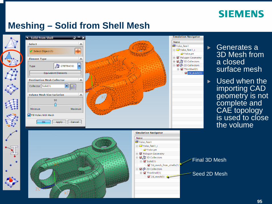
Meshing – Solid from Shell Mesh
Generates a 3D Mesh from a closed surface meshUsed when the importing CAD geometry is not complete and CAE topology is used to close the volume
Seed 2D Mesh
Final 3D Mesh
96
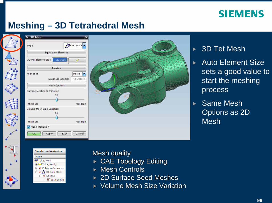
Meshing – 3D Tetrahedral Mesh
3D Tet Mesh
Auto Element Size sets a good value to start the meshing process
Same Mesh Options as 2D Mesh
Mesh qualityMesh qualityCAE Topology EditingCAE Topology EditingMesh ControlsMesh Controls2D Surface Seed Meshes2D Surface Seed MeshesVolume Mesh Size VariationVolume Mesh Size Variation
97
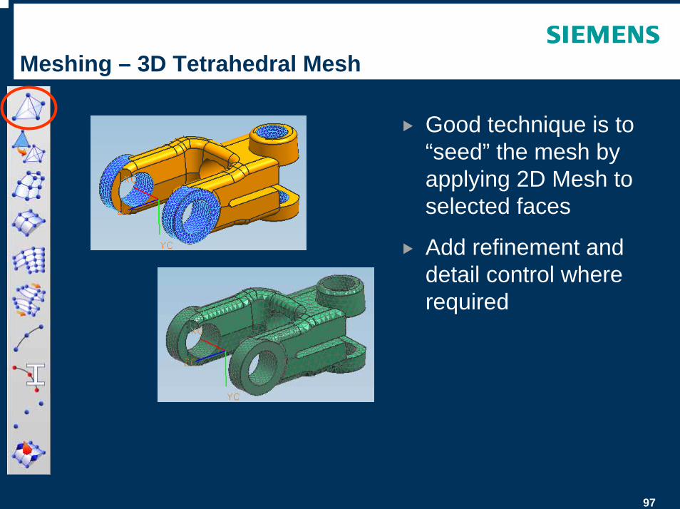
Meshing – 3D Tetrahedral Mesh
Good technique is to “seed” the mesh by applying 2D Mesh to selected faces
Add refinement and detail control where required
98
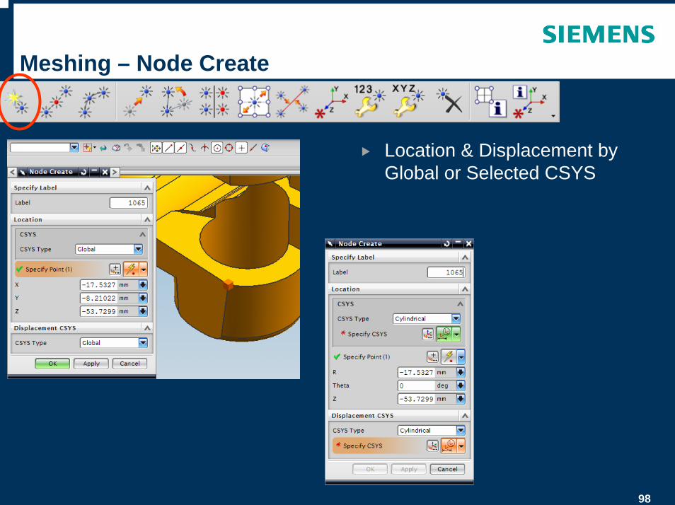
Meshing – Node Create
Location & Displacement by Global or Selected CSYS

99
Meshing – Node Between Nodes
Place Nodes equidistant between 2 selected Nodes
Geometry independent ie does not track surface(s) between Nodes
Displacement by Global or Selected CSYS
100
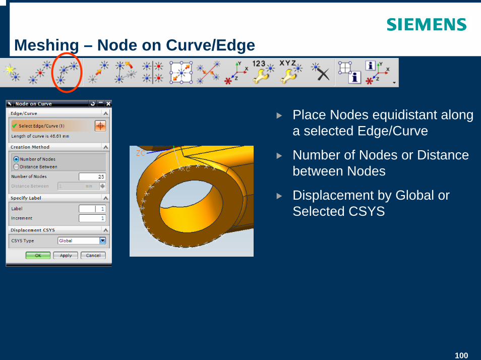
Meshing – Node on Curve/Edge
Place Nodes equidistant along a selected Edge/Curve
Number of Nodes or Distance between Nodes
Displacement by Global or Selected CSYS
101
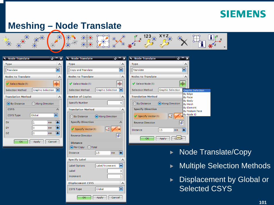
Meshing – Node Translate
Node Translate/Copy
Multiple Selection Methods
Displacement by Global or Selected CSYS
102
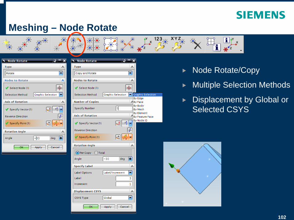
Meshing – Node Rotate
Node Rotate/Copy
Multiple Selection Methods
Displacement by Global or Selected CSYS
103
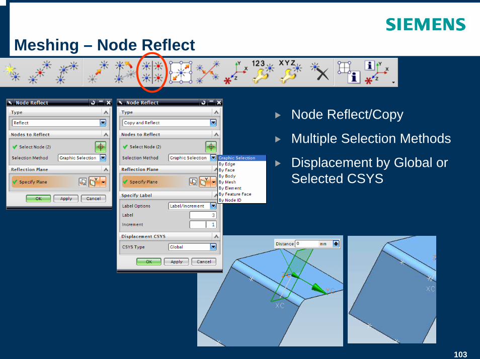
Meshing – Node Reflect
Node Reflect/Copy
Multiple Selection Methods
Displacement by Global or Selected CSYS
104
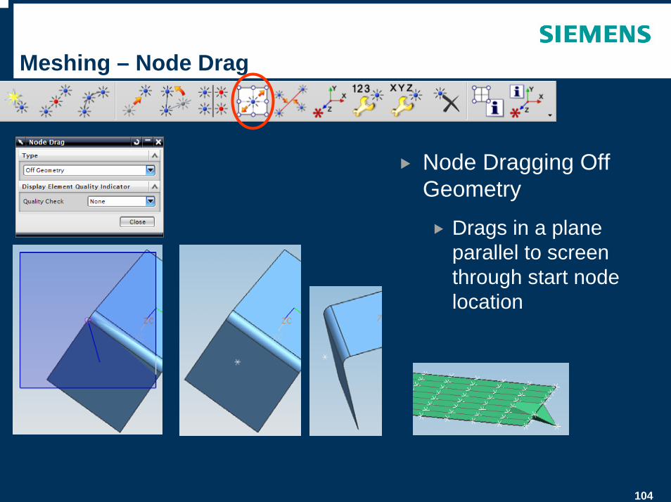
Meshing – Node Drag
Node Dragging Off Geometry
Drags in a plane parallel to screen through start node location
105
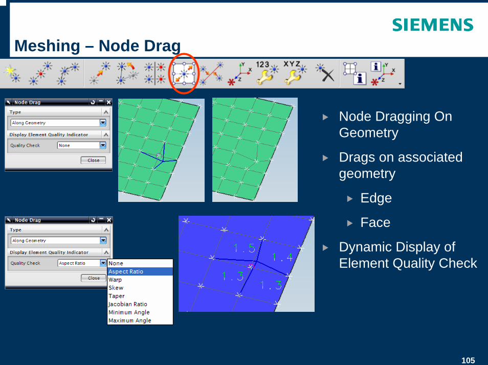
Meshing – Node Drag
Node Dragging On Geometry
Drags on associated geometry
Edge
Face
Dynamic Display of Element Quality Check
106
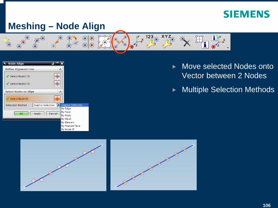
Meshing – Node Align
Move selected Nodes onto Vector between 2 Nodes
Multiple Selection Methods
107
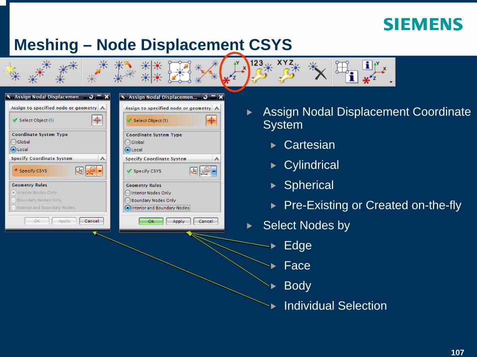
Meshing – Node Displacement CSYS
Assign Nodal Displacement Coordinate System
Cartesian
Cylindrical
Spherical
Pre-Existing or Created on-the-fly
Select Nodes by
Edge
Face
Body
Individual Selection
108
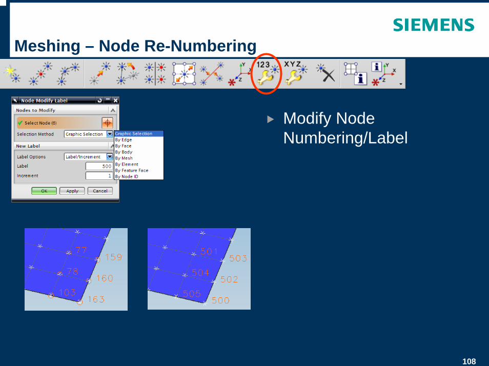
Meshing – Node Re-Numbering
Modify Node Numbering/Label
109
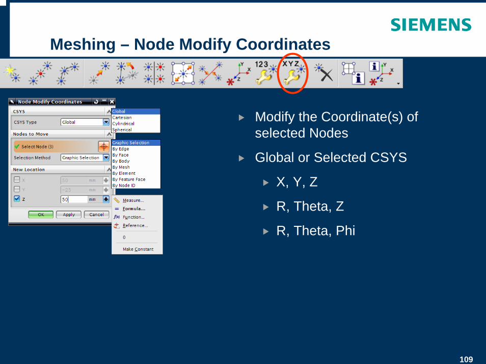
Meshing – Node Modify Coordinates
Modify the Coordinate(s) of selected Nodes
Global or Selected CSYS
X, Y, Z
R, Theta, Z
R, Theta, Phi
110
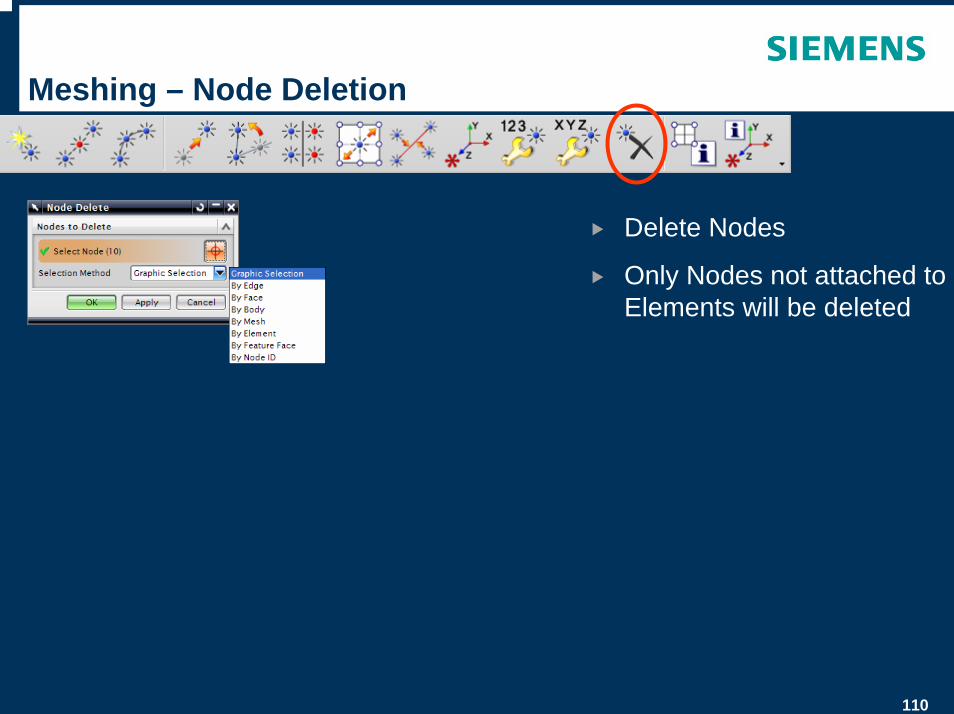
Meshing – Node Deletion
Delete Nodes
Only Nodes not attached to Elements will be deleted
111
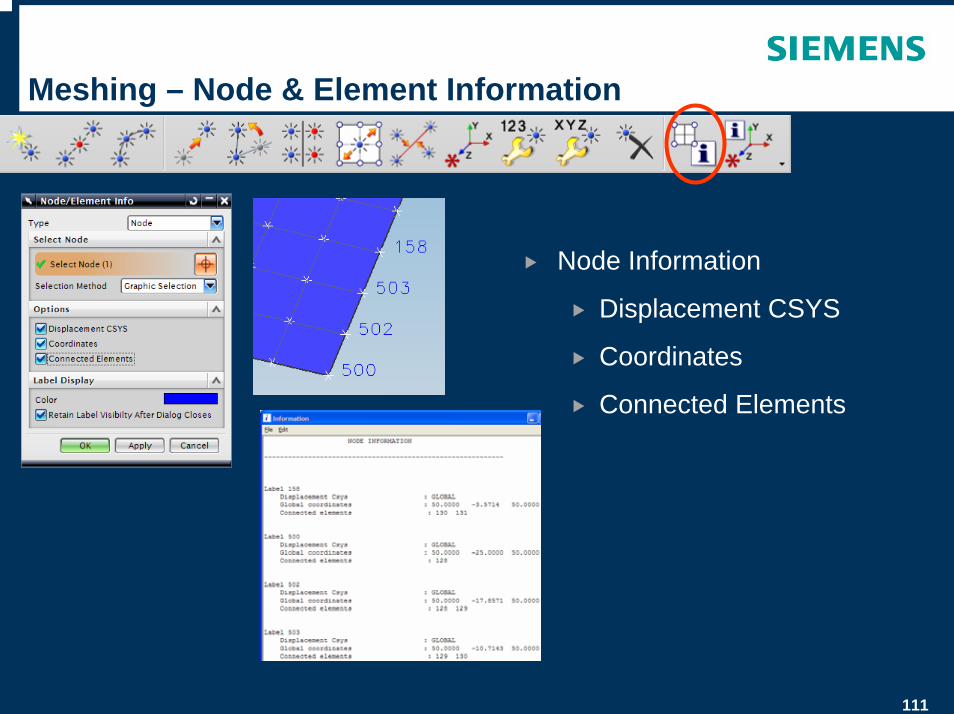
Meshing – Node & Element Information
Node Information
Displacement CSYS
Coordinates
Connected Elements
112
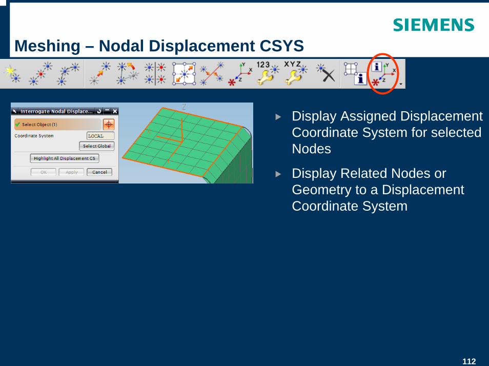
Meshing – Nodal Displacement CSYS
Display Assigned Displacement Coordinate System for selected Nodes
Display Related Nodes or Geometry to a Displacement Coordinate System
113
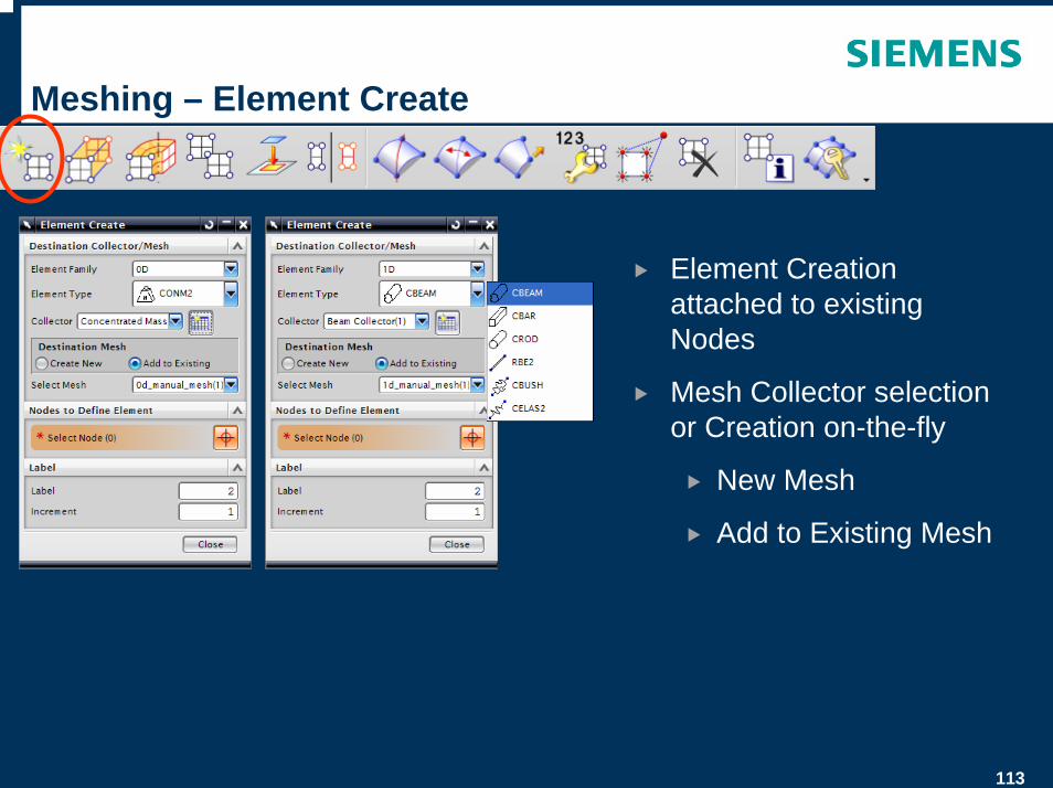
Meshing – Element Create
Element Creation attached to existing Nodes
Mesh Collector selection or Creation on-the-fly
New Mesh
Add to Existing Mesh
114
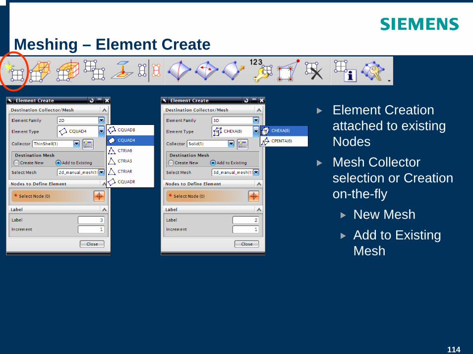
Meshing – Element Create
Element Creation attached to existing NodesMesh Collector selection or Creation on-the-fly
New MeshAdd to Existing Mesh
115
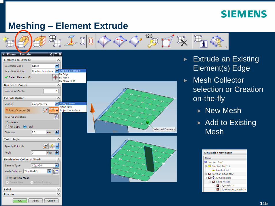
Meshing – Element Extrude
Extrude an Existing Element(s) EdgeMesh Collector selection or Creation on-the-fly
New MeshAdd to Existing Mesh
116
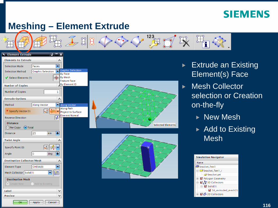
Meshing – Element Extrude
Extrude an Existing Element(s) FaceMesh Collector selection or Creation on-the-fly
New MeshAdd to Existing Mesh
117
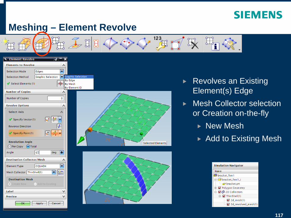
Meshing – Element Revolve
Revolves an Existing Element(s) EdgeMesh Collector selection or Creation on-the-fly
New MeshAdd to Existing Mesh
118
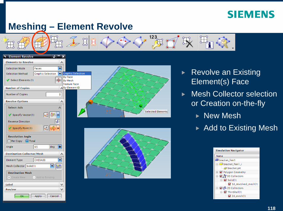
Meshing – Element Revolve
Revolve an Existing Element(s) FaceMesh Collector selection or Creation on-the-fly
New MeshAdd to Existing Mesh
119
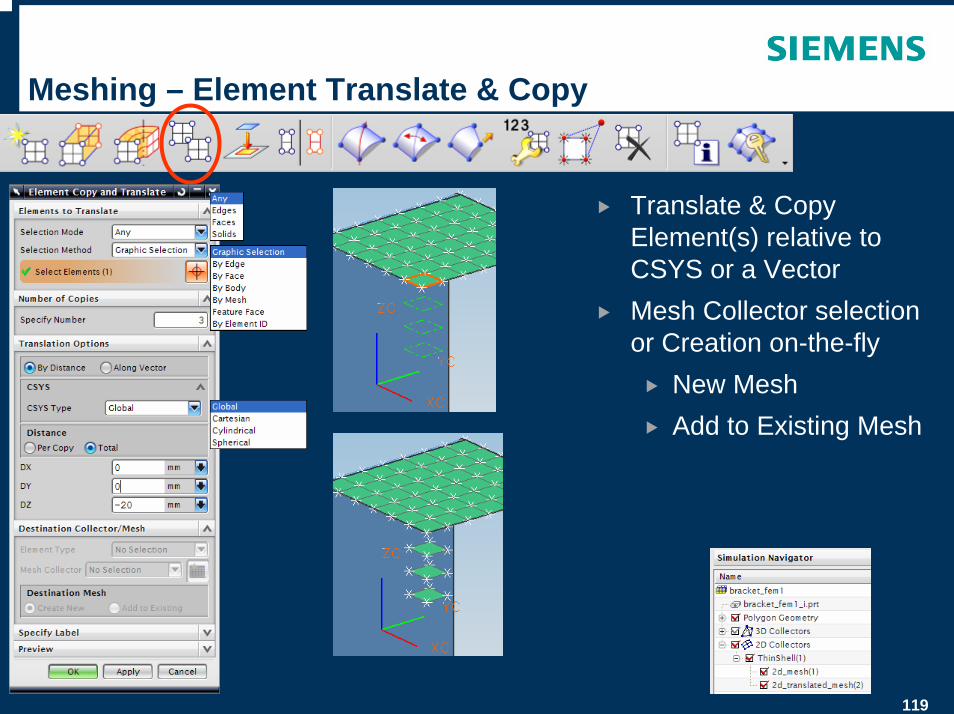
Meshing – Element Translate & Copy
Translate & Copy Element(s) relative to CSYS or a VectorMesh Collector selection or Creation on-the-fly
New MeshAdd to Existing Mesh
120
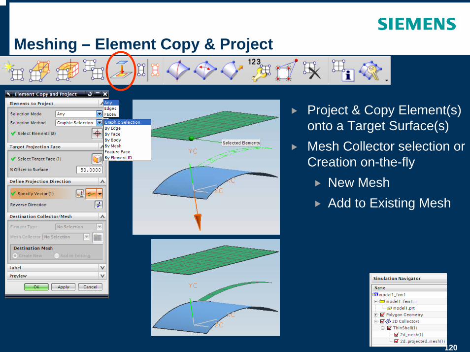
Meshing – Element Copy & Project
Project & Copy Element(s) onto a Target Surface(s)Mesh Collector selection or Creation on-the-fly
New MeshAdd to Existing Mesh
121
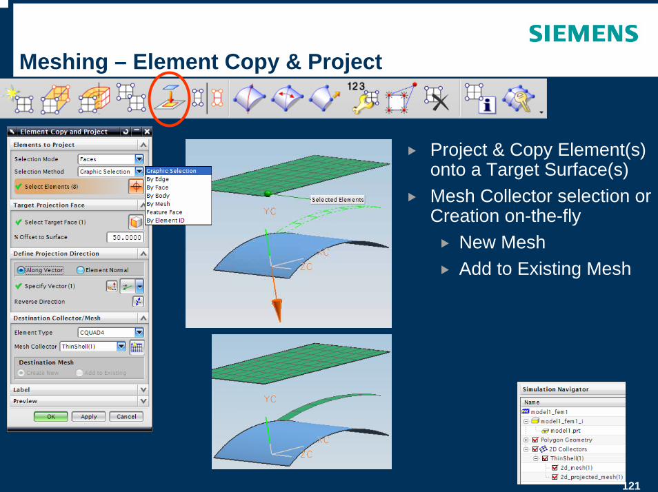
Meshing – Element Copy & Project
Project & Copy Element(s) onto a Target Surface(s)Mesh Collector selection or Creation on-the-fly
New MeshAdd to Existing Mesh
122
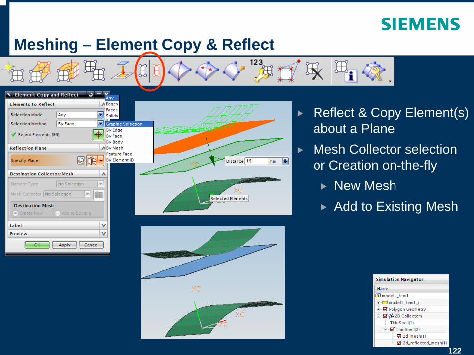
Meshing – Element Copy & Reflect
Reflect & Copy Element(s) about a PlaneMesh Collector selection or Creation on-the-fly
New MeshAdd to Existing Mesh
123
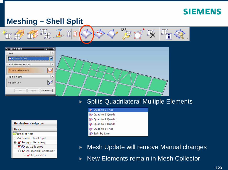
Meshing – Shell Split
Splits Quadrilateral Multiple Elements
Mesh Update will remove Manual changes
New Elements remain in Mesh Collector
124
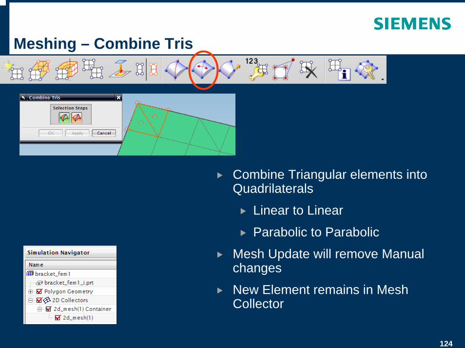
Meshing – Combine Tris
Combine Triangular elements into Quadrilaterals
Linear to Linear
Parabolic to Parabolic
Mesh Update will remove Manual changes
New Element remains in Mesh Collector
125
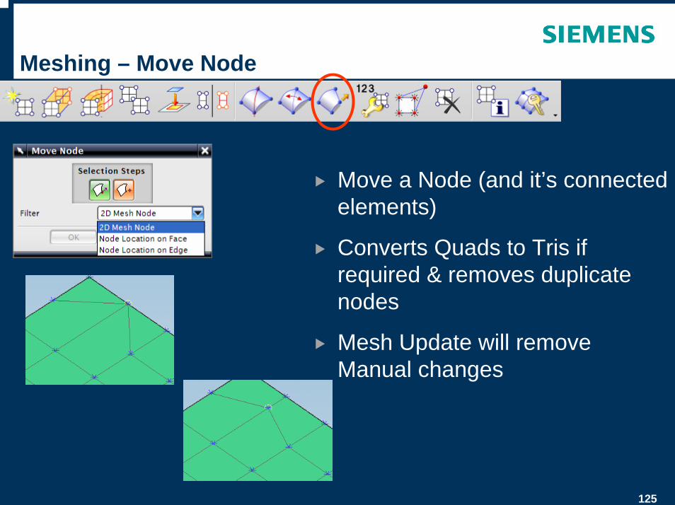
Meshing – Move Node
Move a Node (and it’s connected elements)
Converts Quads to Tris if required & removes duplicate nodes
Mesh Update will remove Manual changes
126
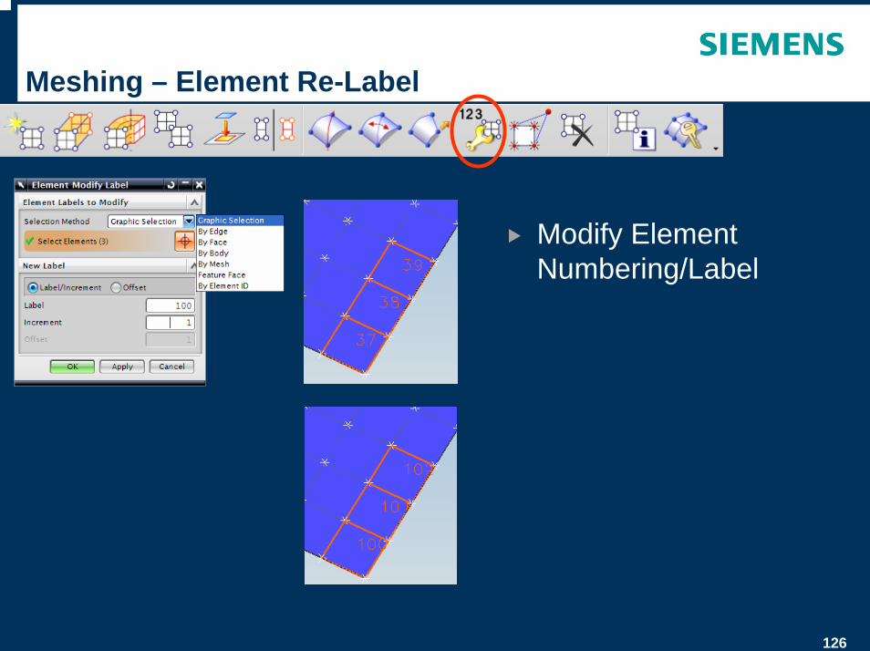
Meshing – Element Re-Label
Modify Element Numbering/Label

127
Meshing – Element Connectivity
Replace One Node with another Node
Specific Mesh Connections
128
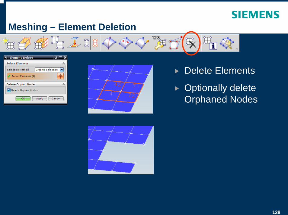
Meshing – Element Deletion
Delete Elements
Optionally delete Orphaned Nodes
129
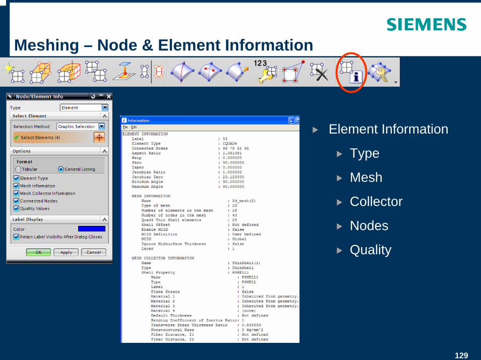
Meshing – Node & Element Information
Element Information
Type
Mesh
Collector
Nodes
Quality
130
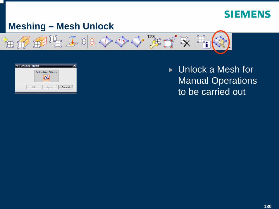
Meshing – Mesh Unlock
Unlock a Mesh for Manual Operations to be carried out
131
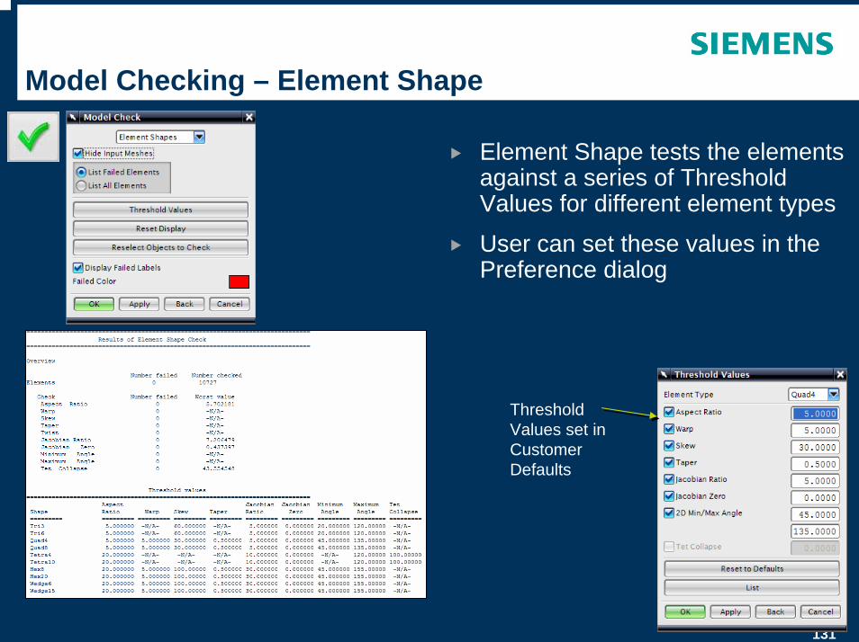
Model Checking – Element Shape
Element Shape tests the elements against a series of Threshold Values for different element types
User can set these values in the Preference dialog
Threshold Values set in Customer Defaults
132
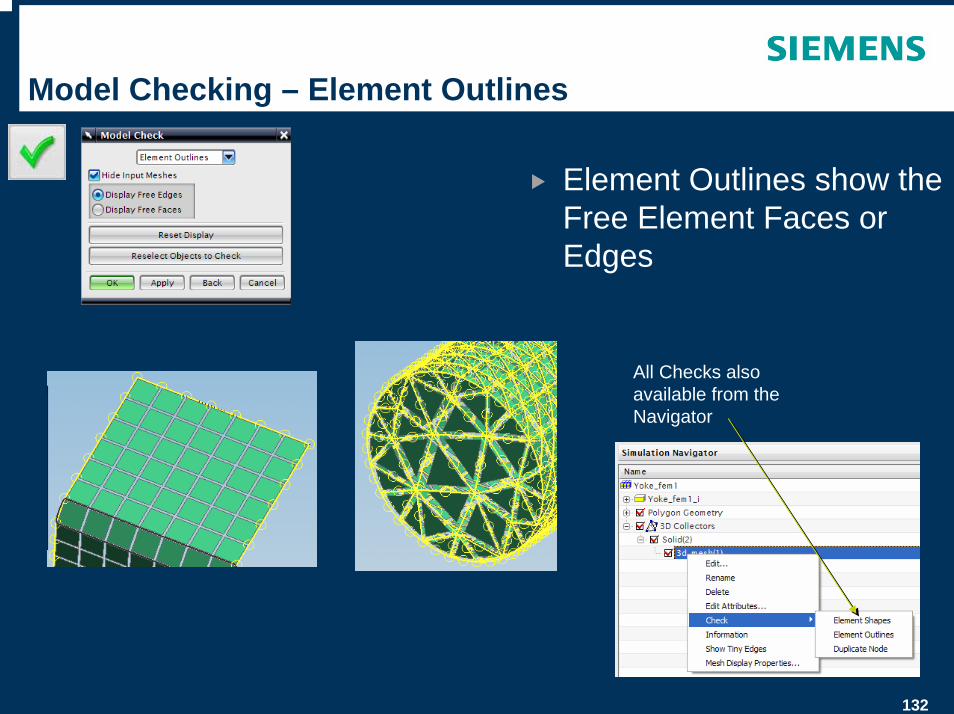
Model Checking – Element Outlines
Element Outlines show the Free Element Faces or Edges
All Checks also available from the Navigator
133
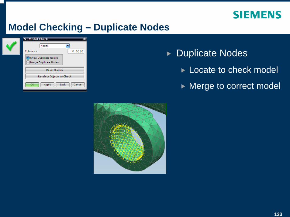
Model Checking – Duplicate Nodes
Duplicate Nodes
Locate to check model
Merge to correct model
134
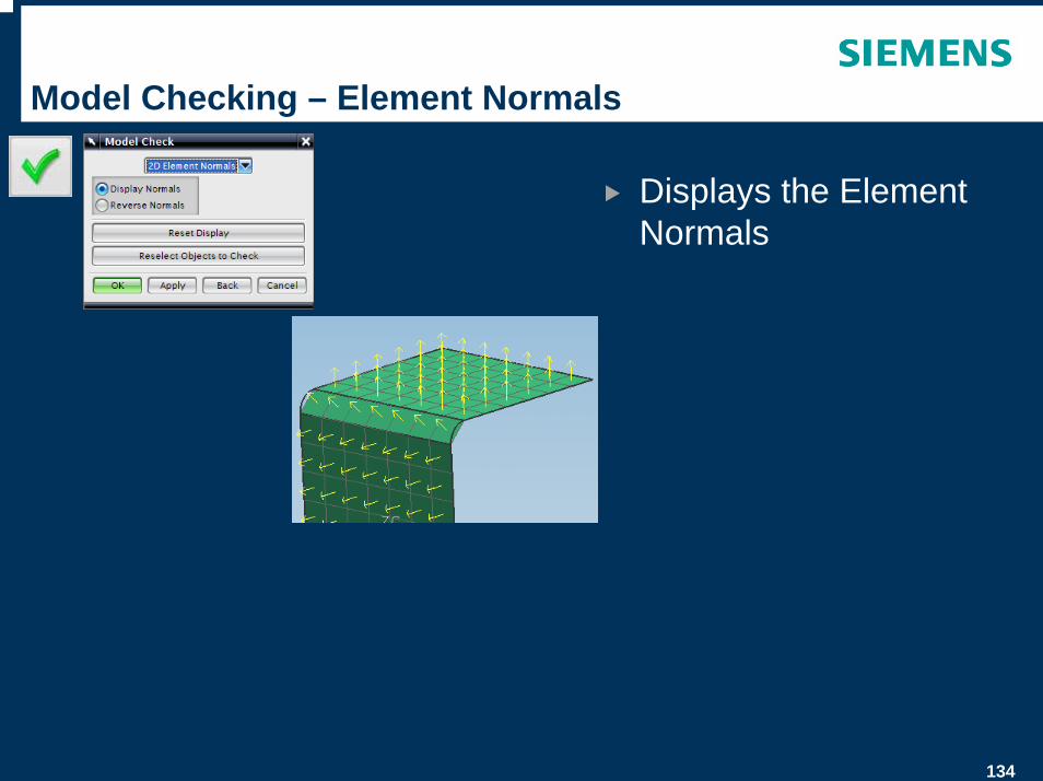
Model Checking – Element Normals
Displays the Element Normals
© UGS Corp. 2007. All rights reserved. UGS PLM Software
SIM Part – Pre-Processing
136
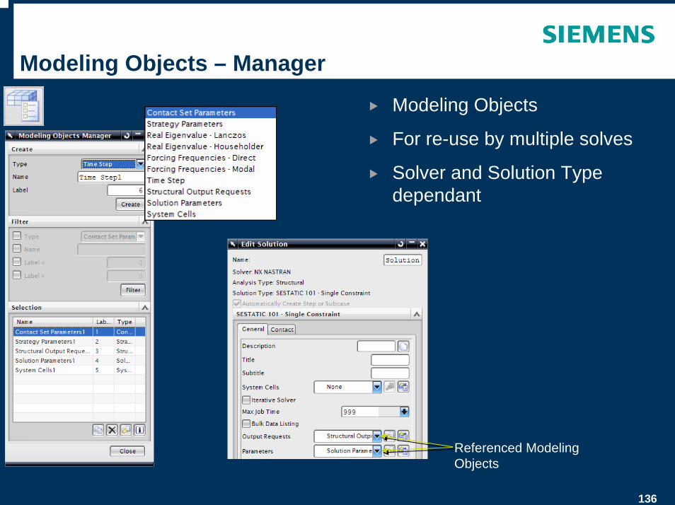
Modeling Objects – Manager
Modeling Objects
For re-use by multiple solves
Solver and Solution Type dependant
Referenced Modeling Objects
137
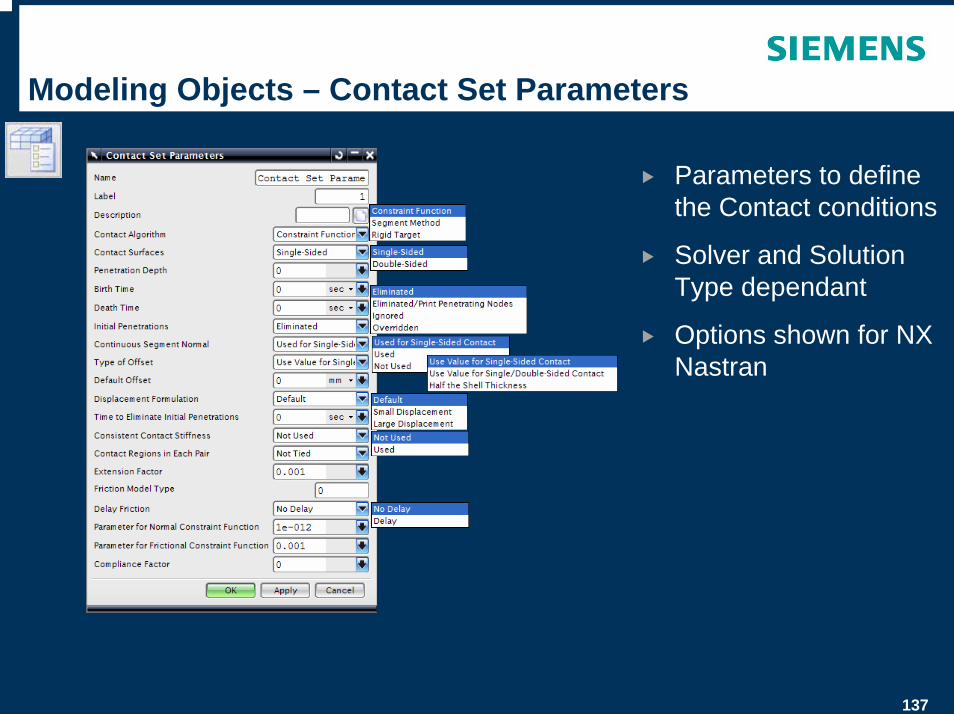
Modeling Objects – Contact Set Parameters
Parameters to define the Contact conditions
Solver and Solution Type dependant
Options shown for NX Nastran
138
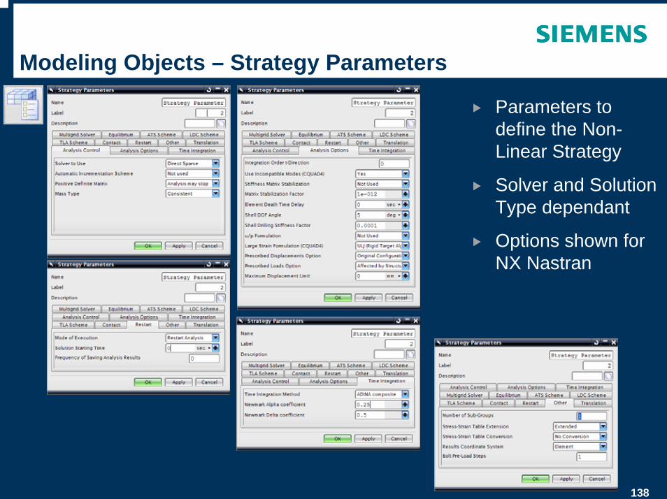
Modeling Objects – Strategy Parameters
Parameters to define the Non-Linear Strategy
Solver and Solution Type dependant
Options shown for NX Nastran
139
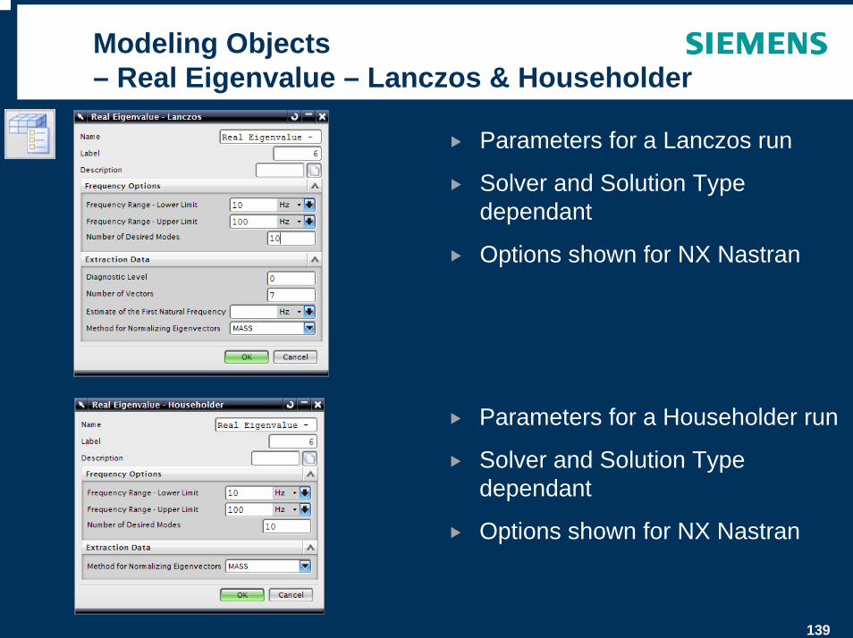
Modeling Objects – Real Eigenvalue – Lanczos & Householder
Parameters for a Lanczos run
Solver and Solution Type dependant
Options shown for NX Nastran
Parameters for a Householder run
Solver and Solution Type dependant
Options shown for NX Nastran
140
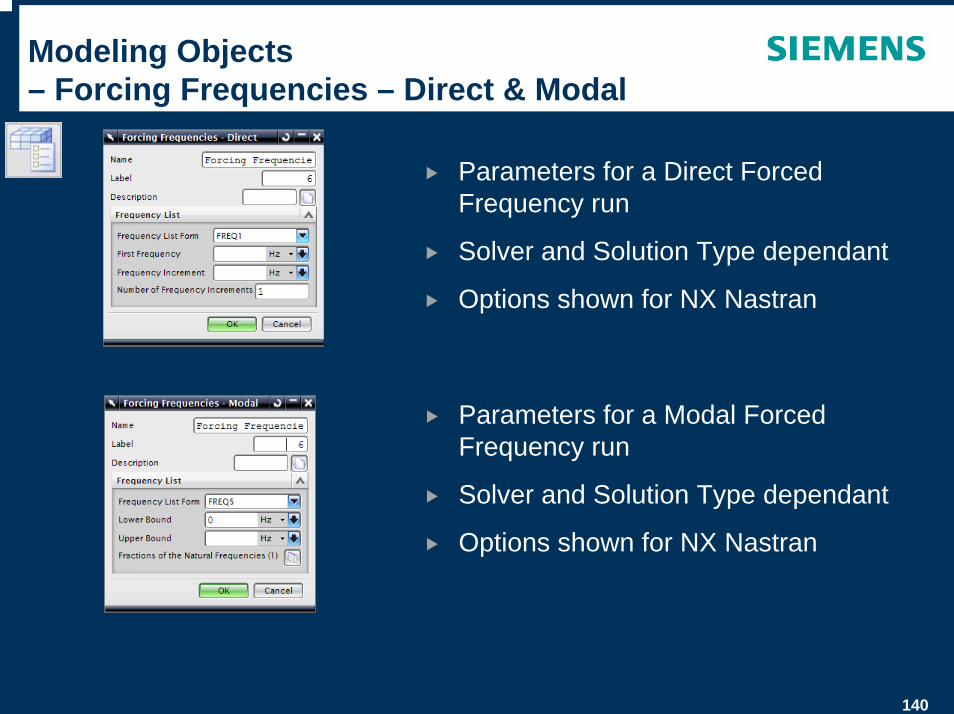
Modeling Objects – Forcing Frequencies – Direct & Modal
Parameters for a Direct Forced Frequency run
Solver and Solution Type dependant
Options shown for NX Nastran
Parameters for a Modal Forced Frequency run
Solver and Solution Type dependant
Options shown for NX Nastran
141
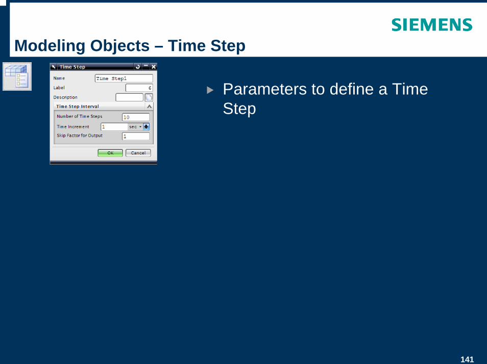
Modeling Objects – Time Step
Parameters to define a Time Step
142
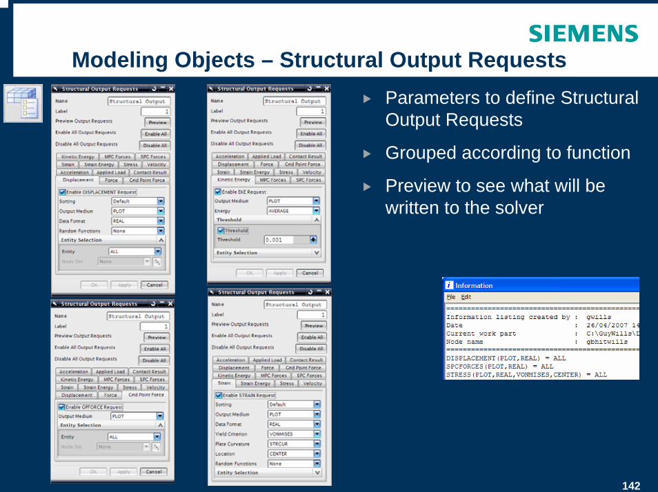
Modeling Objects – Structural Output RequestsParameters to define Structural Output Requests
Grouped according to function
Preview to see what will be written to the solver
143
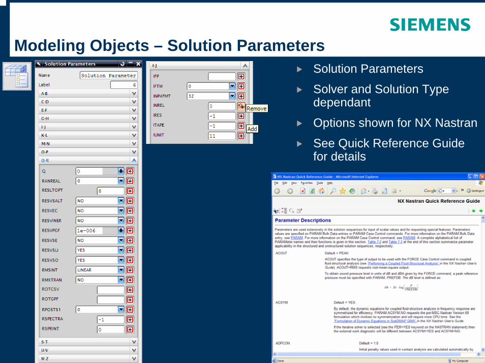
Modeling Objects – Solution ParametersSolution Parameters
Solver and Solution Type dependant
Options shown for NX Nastran
See Quick Reference Guide for details
144
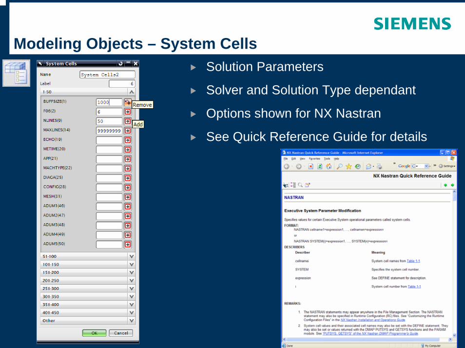
Modeling Objects – System CellsSolution Parameters
Solver and Solution Type dependant
Options shown for NX Nastran
See Quick Reference Guide for details

145
Surface to Surface – Contact
Surface to Surface Contact options
Automatic Detection or Manual Selection
Coefficient of Friction
Search distances
Offsets
146
Surface to Surface – Glue
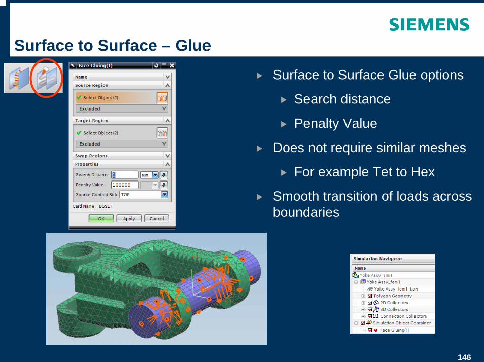
Surface to Surface Glue options
Search distance
Penalty Value
Does not require similar meshes
For example Tet to Hex
Smooth transition of loads across boundaries
147
Loads – Force
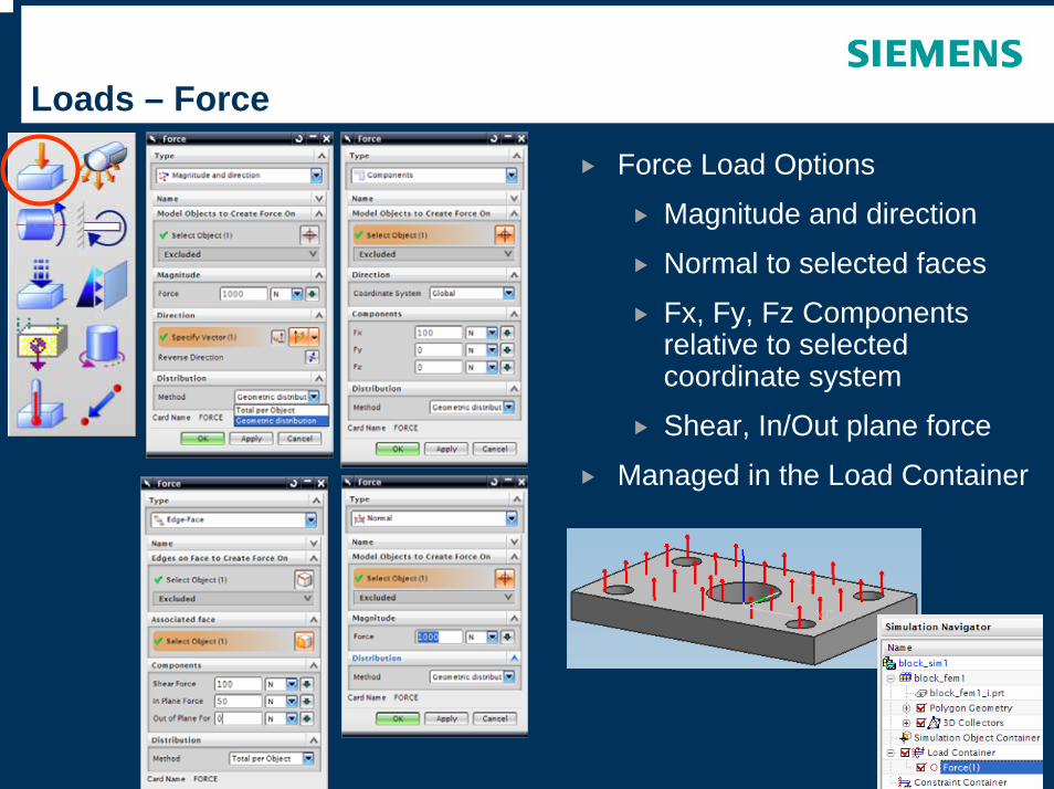
Force Load Options
Magnitude and direction
Normal to selected faces
Fx, Fy, Fz Components relative to selected coordinate system
Shear, In/Out plane force
Managed in the Load Container
148
Loads – Bearing
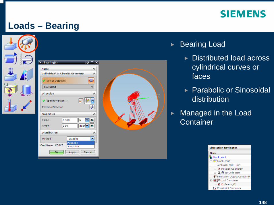
Bearing Load
Distributed load across cylindrical curves or faces
Parabolic or Sinosoidal distribution
Managed in the Load Container
149
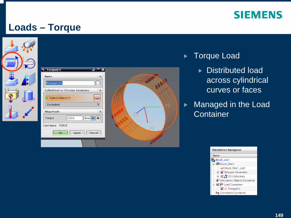
Loads – Torque
Torque Load
Distributed load across cylindrical curves or faces
Managed in the Load Container
150
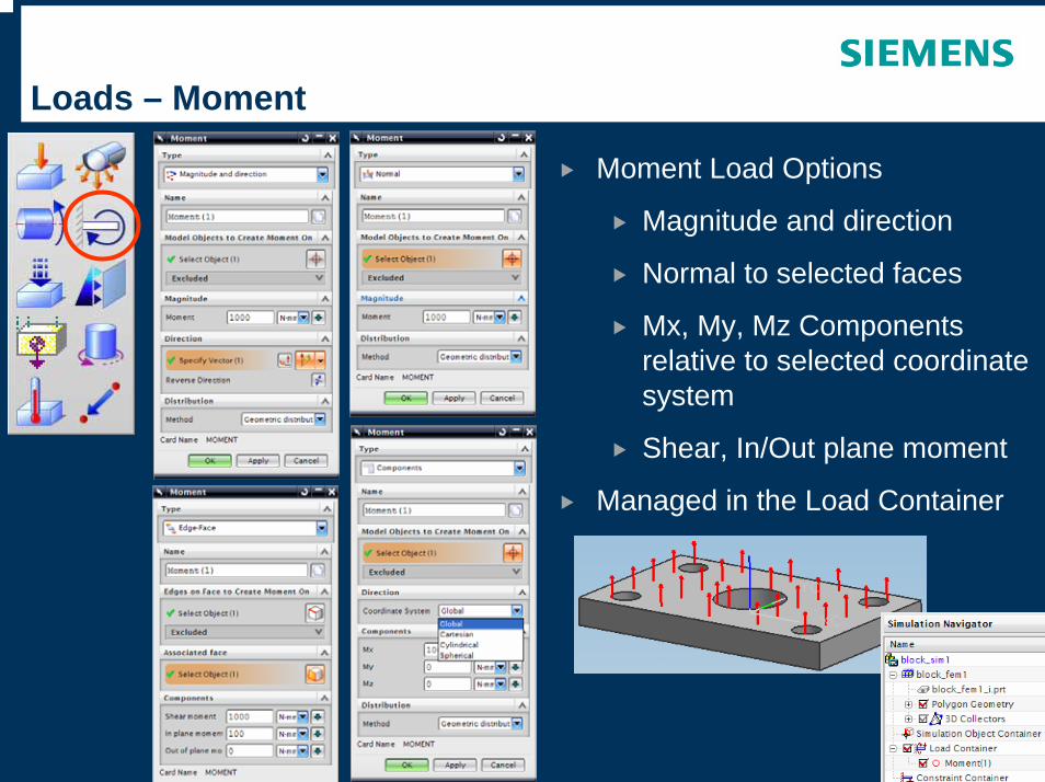
Loads – Moment
Moment Load Options
Magnitude and direction
Normal to selected faces
Mx, My, Mz Components relative to selected coordinate system
Shear, In/Out plane moment
Managed in the Load Container
151
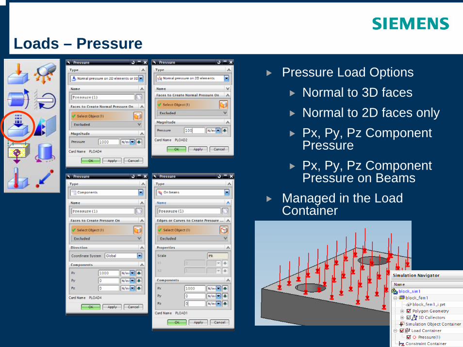
Loads – Pressure
Pressure Load OptionsNormal to 3D facesNormal to 2D faces onlyPx, Py, Pz Component PressurePx, Py, Pz Component Pressure on Beams
Managed in the Load Container
152
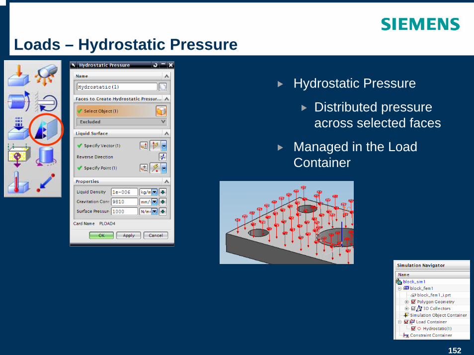
Loads – Hydrostatic Pressure
Hydrostatic Pressure
Distributed pressure across selected faces
Managed in the Load Container
153
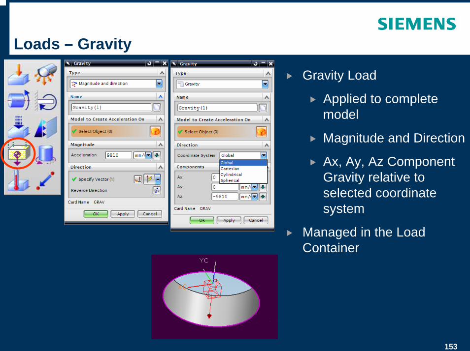
Loads – Gravity
Gravity Load
Applied to complete model
Magnitude and Direction
Ax, Ay, Az Component Gravity relative to selected coordinate system
Managed in the Load Container
154
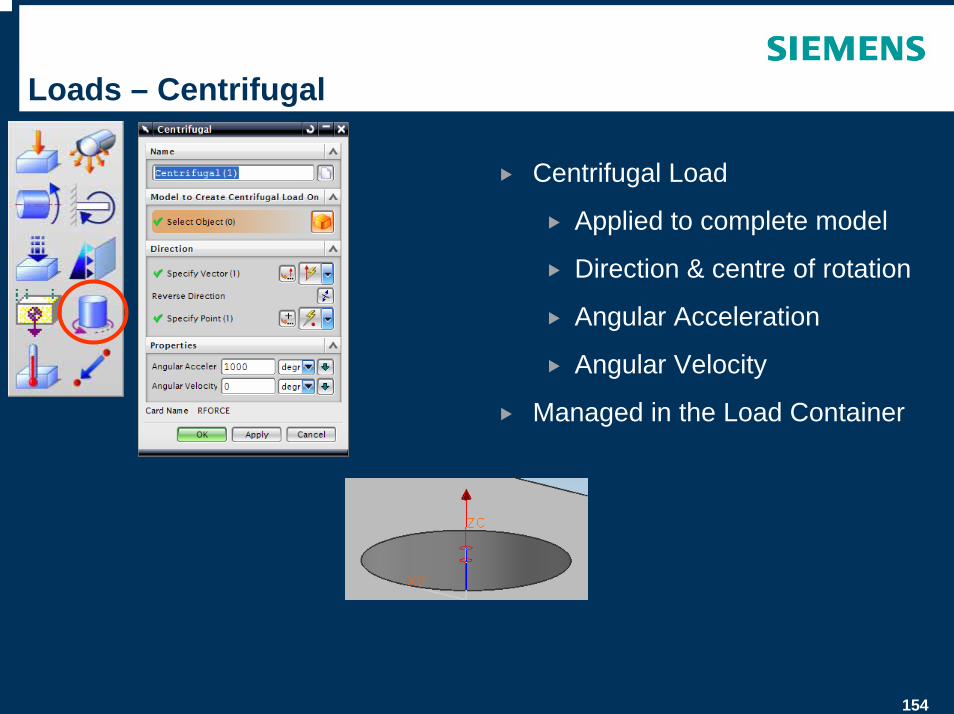
Loads – Centrifugal
Centrifugal Load
Applied to complete model
Direction & centre of rotation
Angular Acceleration
Angular Velocity
Managed in the Load Container
155
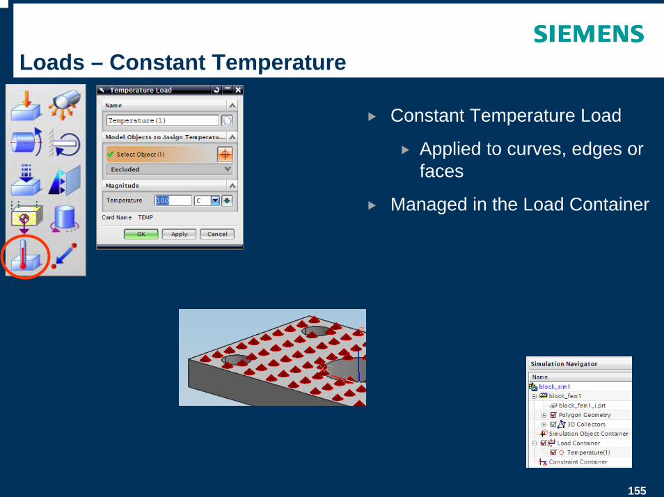
Loads – Constant Temperature
Constant Temperature Load
Applied to curves, edges or faces
Managed in the Load Container
156
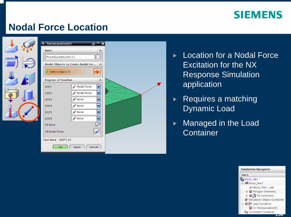
Nodal Force Location
Location for a Nodal Force Excitation for the NX Response Simulation application
Requires a matching Dynamic Load
Managed in the Load Container
157
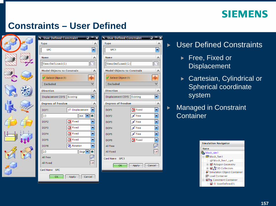
Constraints – User Defined
User Defined Constraints
Free, Fixed or Displacement
Cartesian, Cylindrical or Spherical coordinate system
Managed in Constraint Container
158
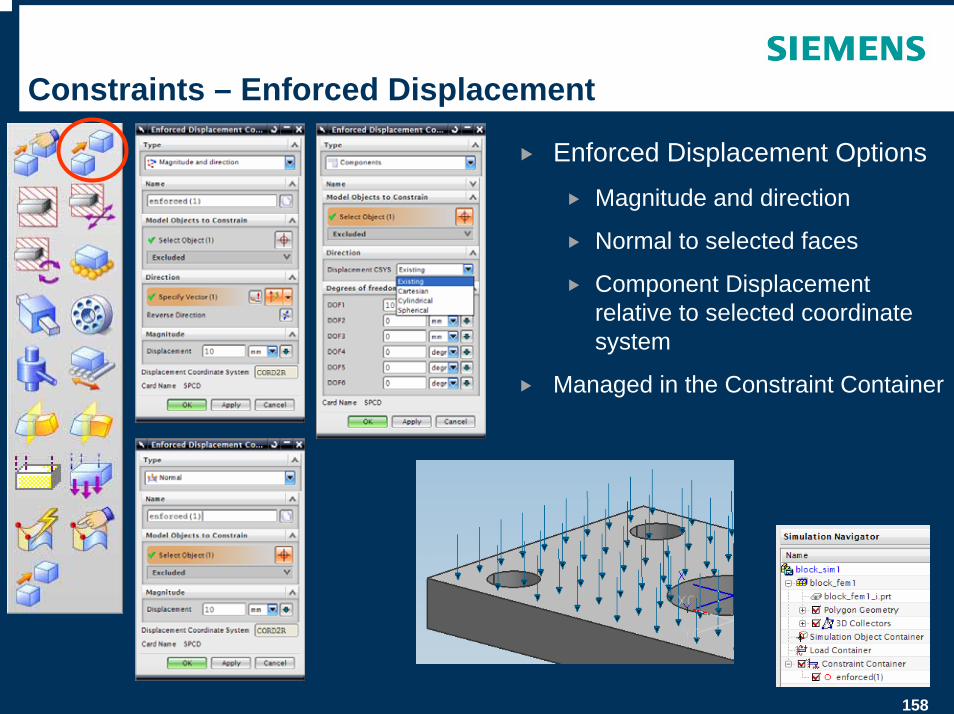
Constraints – Enforced Displacement
Enforced Displacement Options
Magnitude and direction
Normal to selected faces
Component Displacement relative to selected coordinate system
Managed in the Constraint Container
159
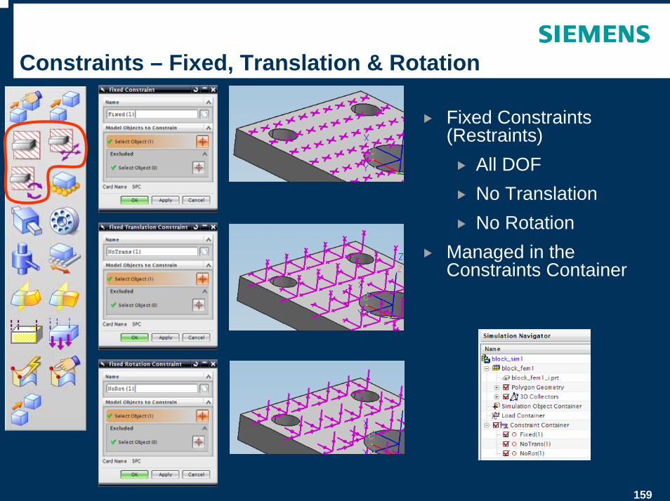
Constraints – Fixed, Translation & Rotation
Fixed Constraints (Restraints)
All DOFNo TranslationNo Rotation
Managed in the Constraints Container
160
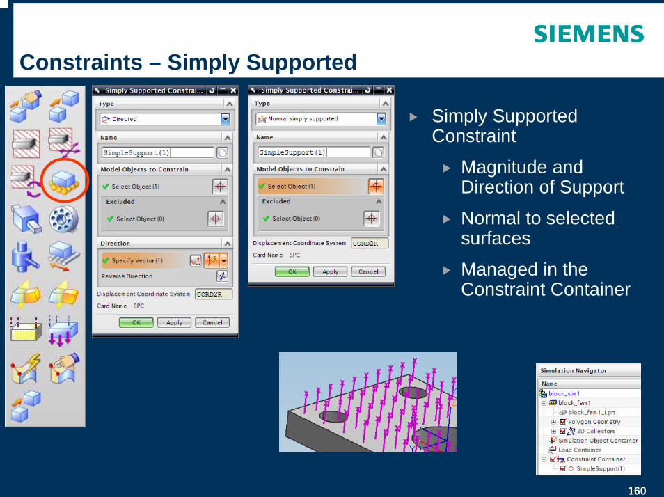
Constraints – Simply Supported
Simply Supported Constraint
Magnitude and Direction of Support
Normal to selected surfaces
Managed in the Constraint Container
161
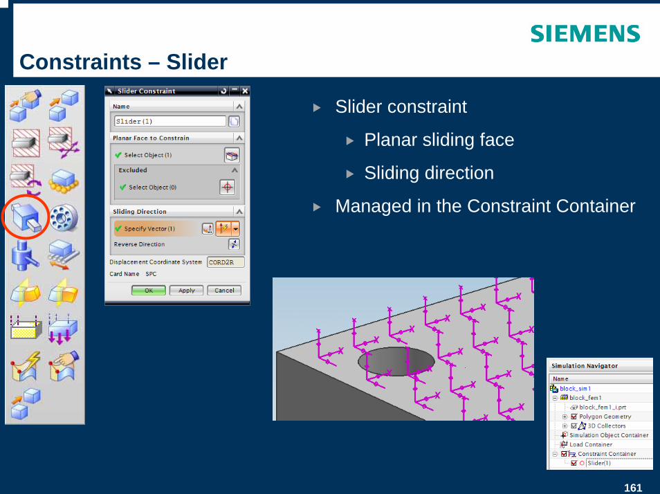
Constraints – Slider
Slider constraint
Planar sliding face
Sliding direction
Managed in the Constraint Container
162
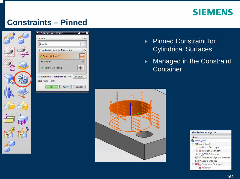
Constraints – Pinned
Pinned Constraint for Cylindrical Surfaces
Managed in the Constraint Container
163
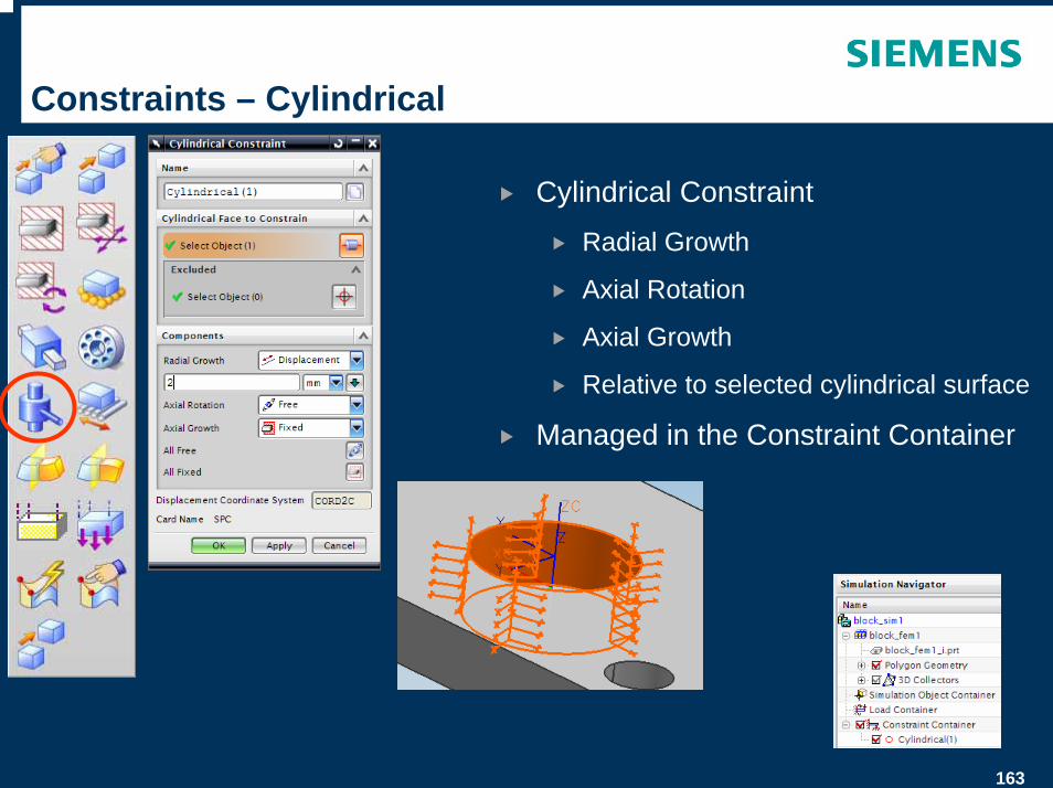
Constraints – Cylindrical
Cylindrical Constraint
Radial Growth
Axial Rotation
Axial Growth
Relative to selected cylindrical surface
Managed in the Constraint Container
164
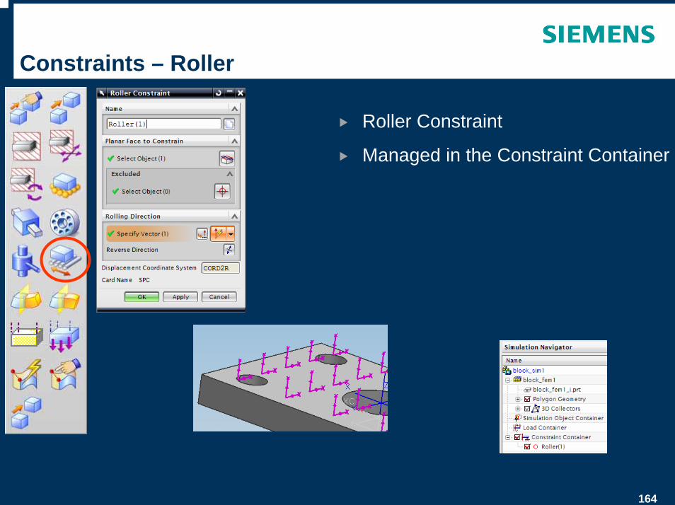
Constraints – Roller
Roller Constraint
Managed in the Constraint Container

165
Constraints – Symmetric
Symmetric Constraint
Managed in the Constraint Container
166
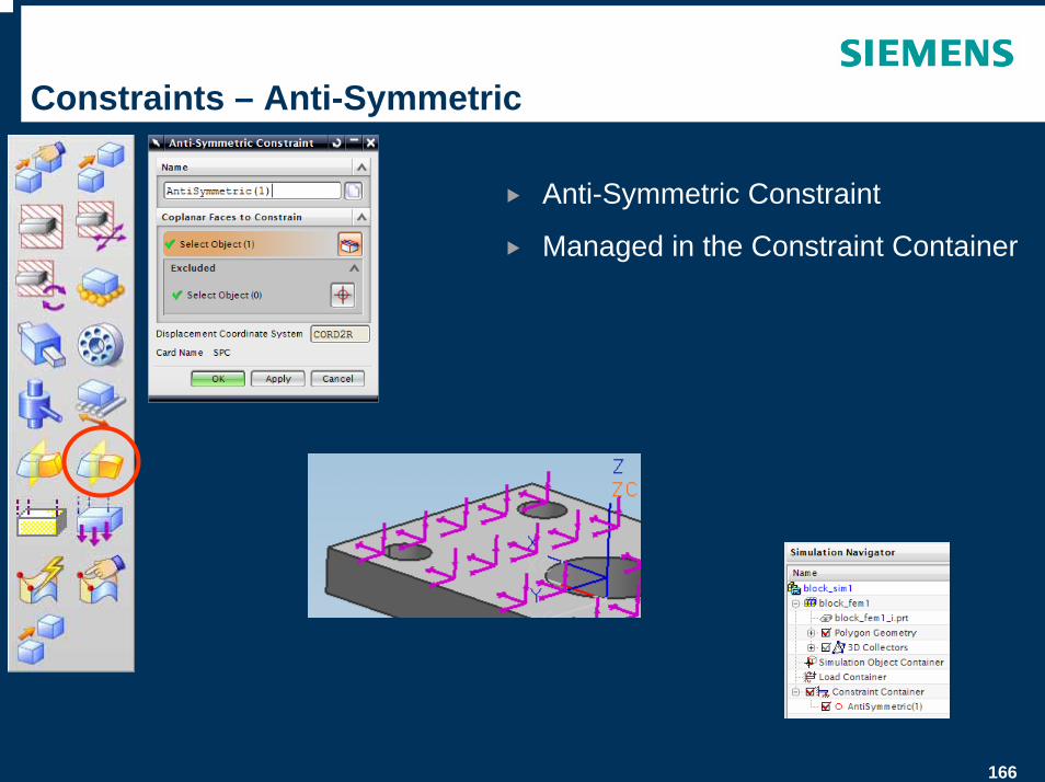
Constraints – Anti-Symmetric
Anti-Symmetric Constraint
Managed in the Constraint Container
167
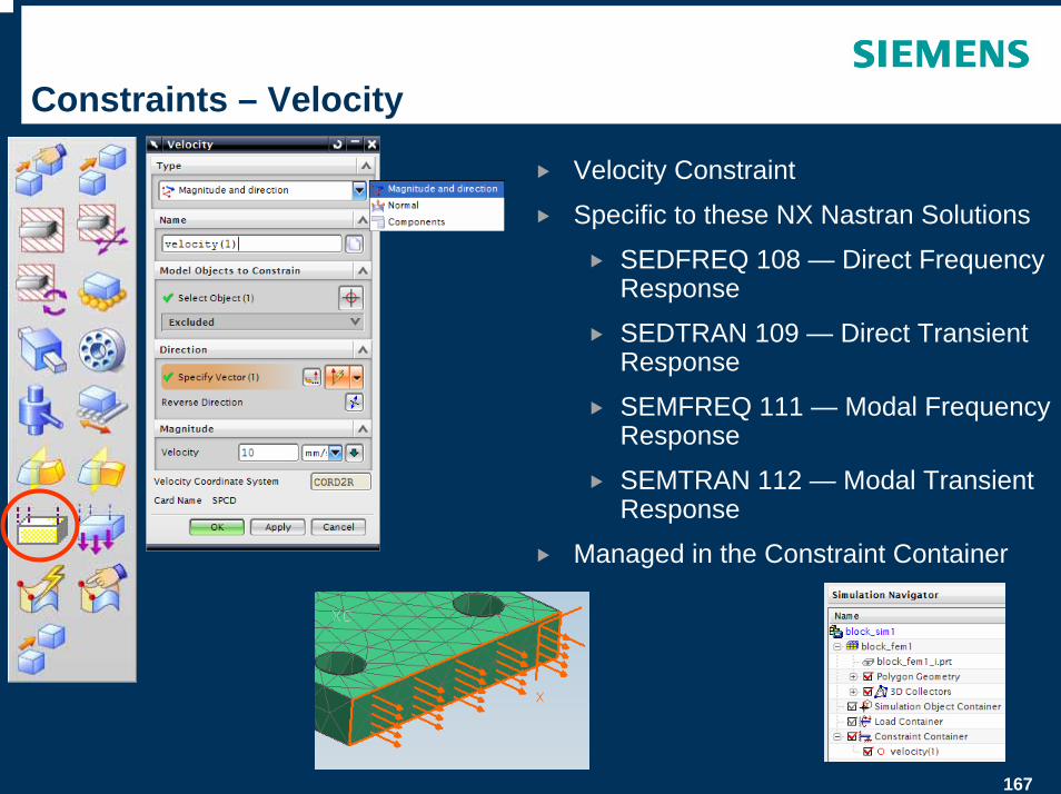
Constraints – Velocity
Velocity Constraint
Specific to these NX Nastran Solutions
SEDFREQ 108 — Direct Frequency Response
SEDTRAN 109 — Direct Transient Response
SEMFREQ 111 — Modal Frequency Response
SEMTRAN 112 — Modal Transient Response
Managed in the Constraint Container
168
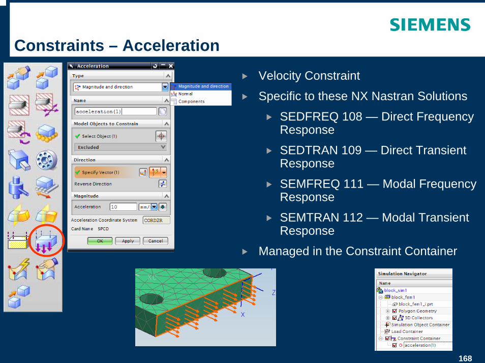
Constraints – Acceleration
Velocity Constraint
Specific to these NX Nastran Solutions
SEDFREQ 108 — Direct Frequency Response
SEDTRAN 109 — Direct Transient Response
SEMFREQ 111 — Modal Frequency Response
SEMTRAN 112 — Modal Transient Response
Managed in the Constraint Container
169
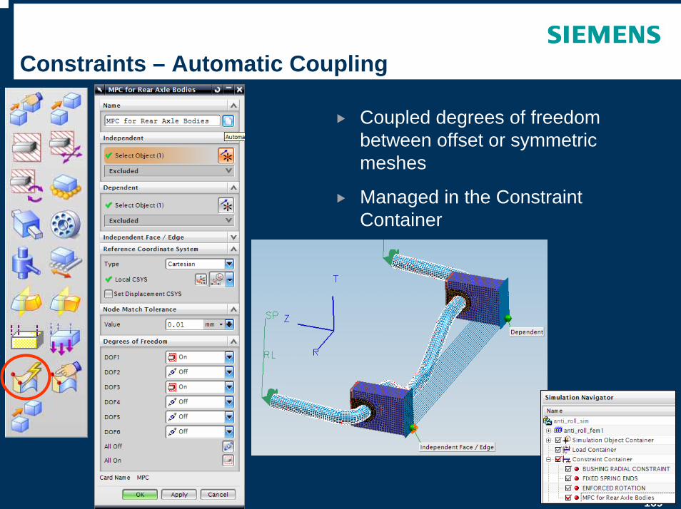
Constraints – Automatic Coupling
Coupled degrees of freedom between offset or symmetric meshes
Managed in the Constraint Container
170
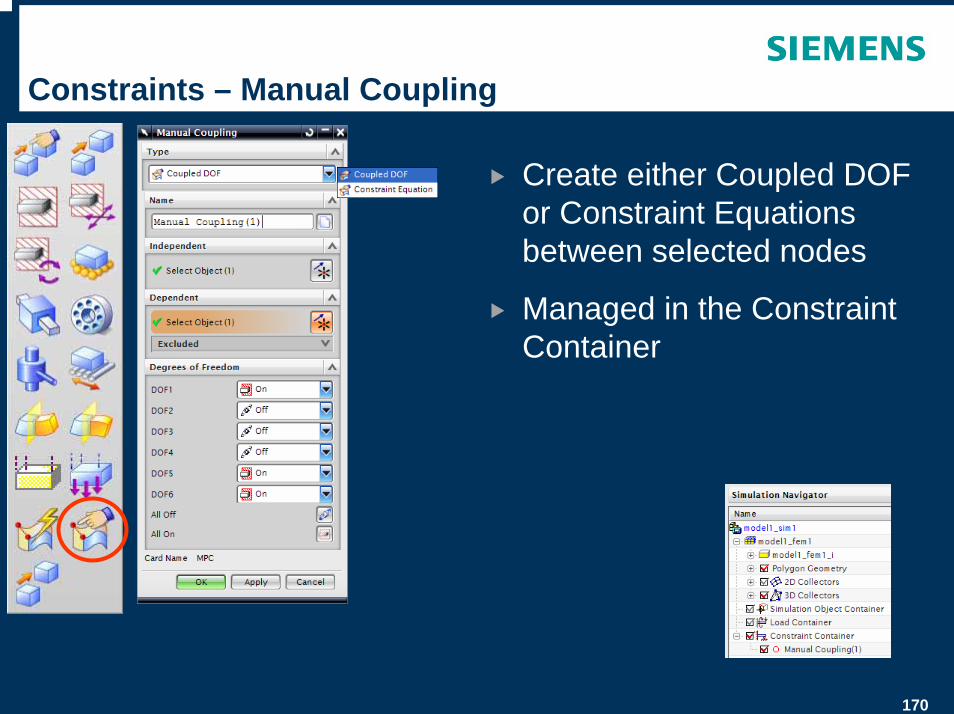
Constraints – Manual Coupling
Create either Coupled DOF or Constraint Equations between selected nodes
Managed in the Constraint Container
171
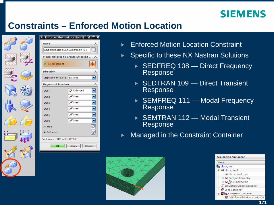
Constraints – Enforced Motion Location
Enforced Motion Location ConstraintSpecific to these NX Nastran Solutions
SEDFREQ 108 — Direct Frequency Response SEDTRAN 109 — Direct Transient Response SEMFREQ 111 — Modal Frequency Response SEMTRAN 112 — Modal Transient Response
Managed in the Constraint Container
172
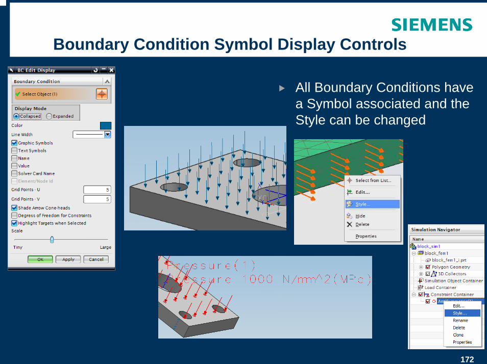
Boundary Condition Symbol Display Controls
All Boundary Conditions have a Symbol associated and the Style can be changed
173
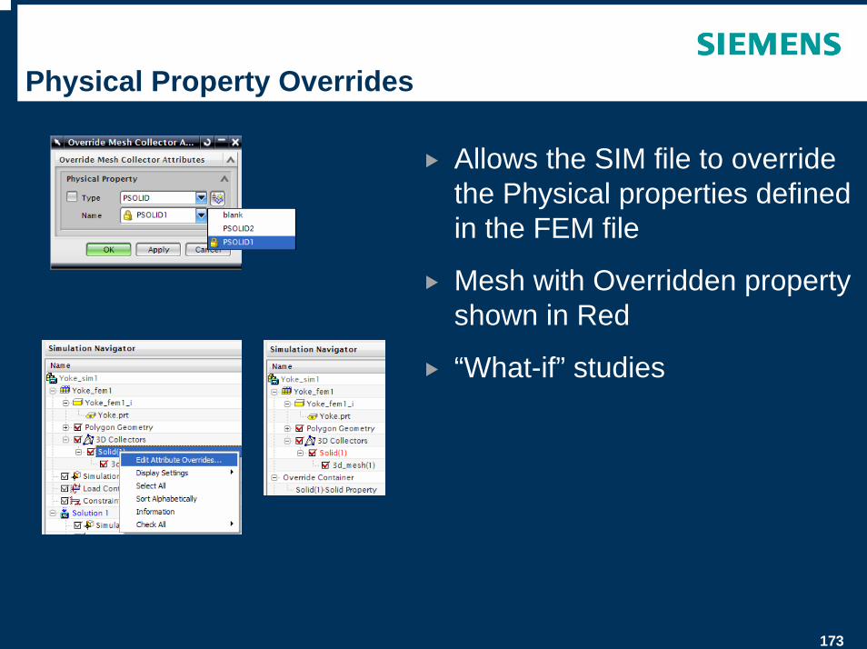
Physical Property Overrides
Allows the SIM file to override the Physical properties defined in the FEM file
Mesh with Overridden property shown in Red
“What-if” studies
174
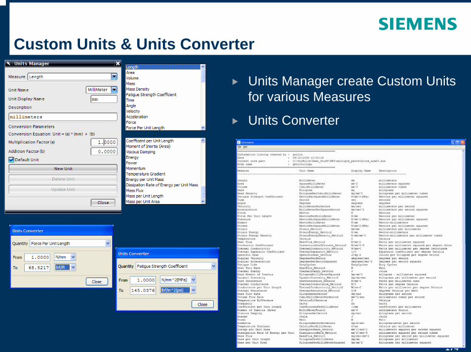
Custom Units & Units Converter
Units Manager create Custom Units for various Measures
Units Converter
175
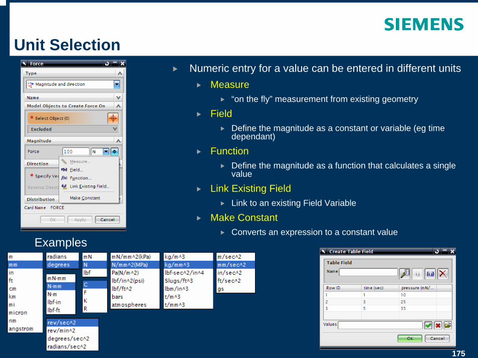
Unit SelectionNumeric entry for a value can be entered in different units
Measure“on the fly” measurement from existing geometry
FieldDefine the magnitude as a constant or variable (eg time dependant)
FunctionDefine the magnitude as a function that calculates a single value
Link Existing FieldLink to an existing Field Variable
Make ConstantConverts an expression to a constant value
Examples
176
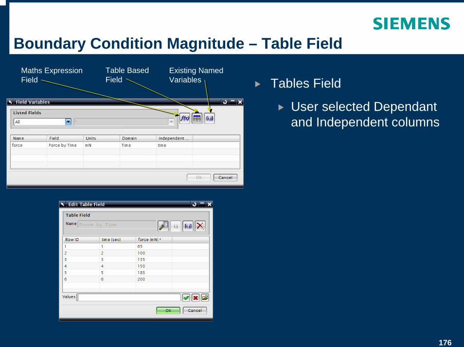
Boundary Condition Magnitude – Table Field
Tables Field
User selected Dependant and Independent columns
Maths Expression Field
Table Based Field
Existing Named Variables
177
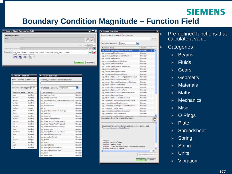
Boundary Condition Magnitude – Function FieldPre-defined functions that calculate a valueCategories
BeamsFluidsGearsGeometryMaterialsMathsMechanicsMiscO RingsPlateSpreadsheetSpringStringUnitsVibration
178
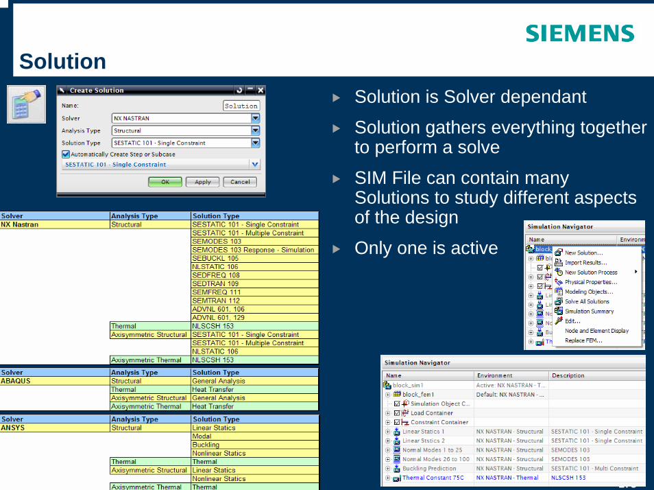
SolutionSolution is Solver dependant
Solution gathers everything together to perform a solve
SIM File can contain many Solutions to study different aspects of the design
Only one is active
179
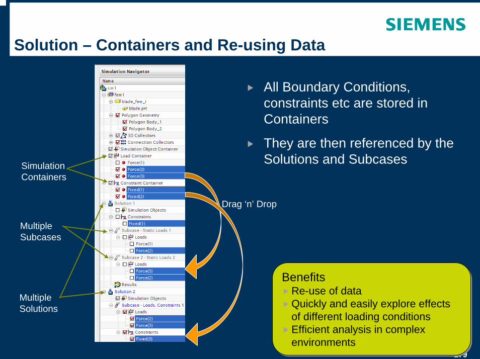
Solution – Containers and Re-using Data
All Boundary Conditions, constraints etc are stored in Containers
They are then referenced by the Solutions and Subcases
BenefitsRe-use of dataQuickly and easily explore effects of different loading conditionsEfficient analysis in complex environments
BenefitsRe-use of dataQuickly and easily explore effects of different loading conditionsEfficient analysis in complex environments
Simulation Containers
Multiple Solutions
Multiple Subcases
Drag ‘n’ Drop
180
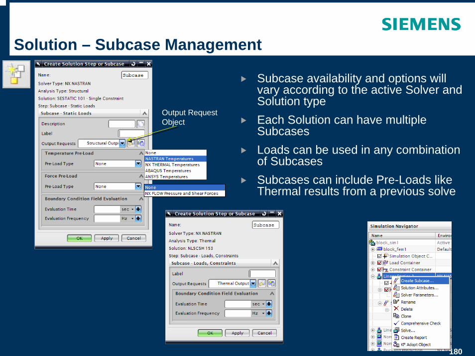
Solution – Subcase Management
Subcase availability and options will vary according to the active Solver and Solution type Each Solution can have multiple SubcasesLoads can be used in any combination of SubcasesSubcases can include Pre-Loads like Thermal results from a previous solve
Output Request Object
181
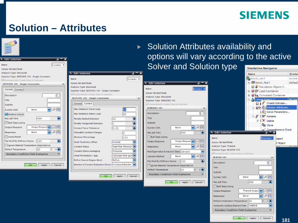
Solution – Attributes
Solution Attributes availability and options will vary according to the active Solver and Solution type
182
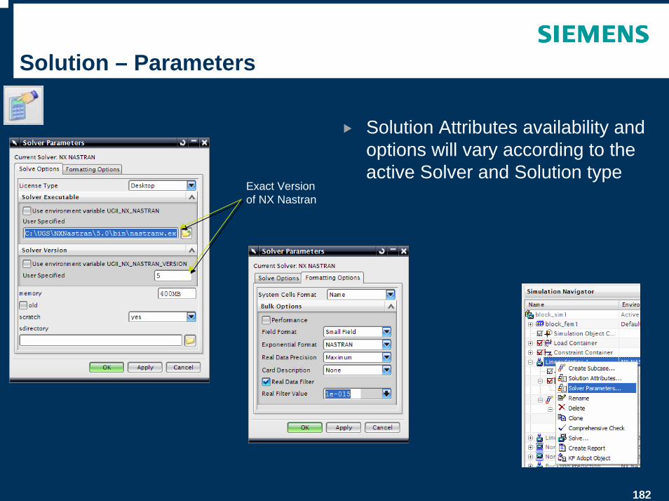
Solution – Parameters
Solution Attributes availability and options will vary according to the active Solver and Solution type
Exact Version of NX Nastran
183
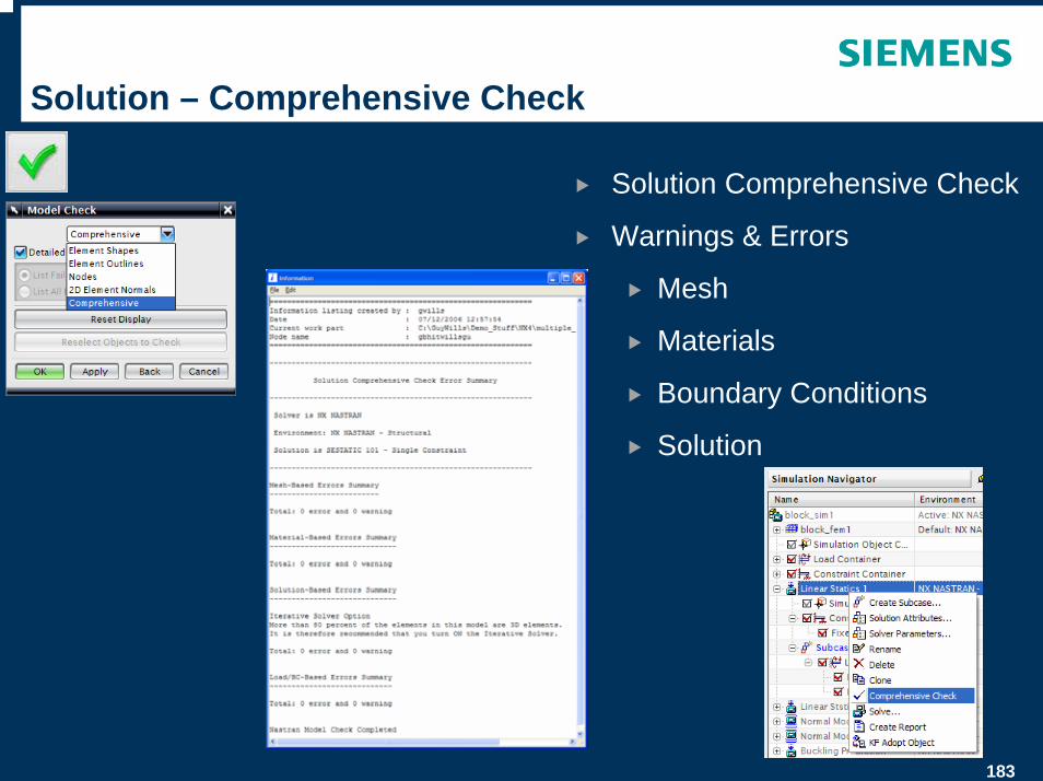
Solution – Comprehensive Check
Solution Comprehensive Check
Warnings & Errors
Mesh
Materials
Boundary Conditions
Solution
184
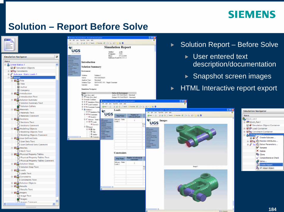
Solution – Report Before Solve
Solution Report – Before Solve
User entered text description/documentation
Snapshot screen images
HTML Interactive report export
185
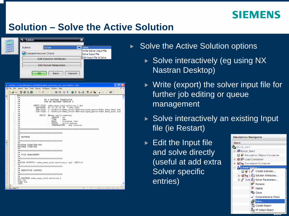
Solution – Solve the Active Solution
Solve the Active Solution options
Solve interactively (eg using NX Nastran Desktop)
Write (export) the solver input file for further job editing or queue management
Solve interactively an existing Input file (ie Restart)
Edit the Input file and solve directly (useful at add extra Solver specific entries)
© UGS Corp. 2007. All rights reserved. UGS PLM Software
SIM Part – Post-Processing
187
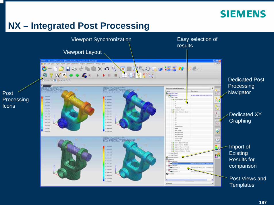
NX – Integrated Post Processing
Post Processing Icons
Post Views and Templates
Viewport Layout
Dedicated Post Processing Navigator
Easy selection of results
Import of Existing Results for comparison
Dedicated XY Graphing
Viewport Synchronization
188
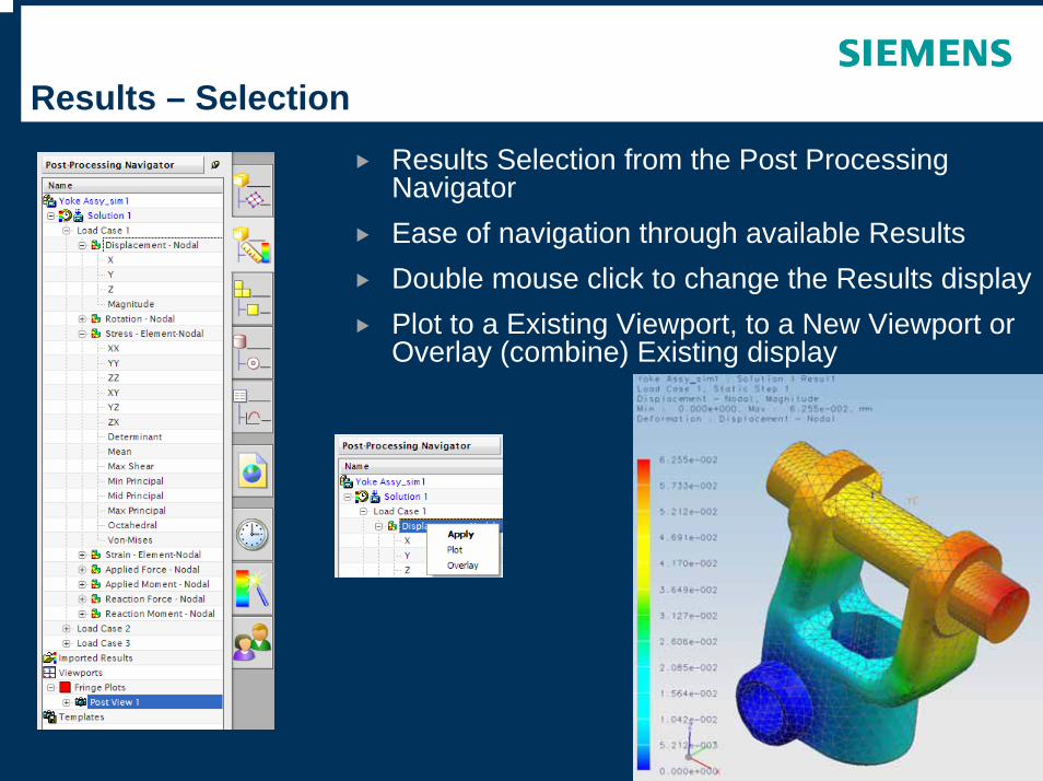
Results – SelectionResults Selection from the Post Processing NavigatorEase of navigation through available ResultsDouble mouse click to change the Results displayPlot to a Existing Viewport, to a New Viewport or Overlay (combine) Existing display
189
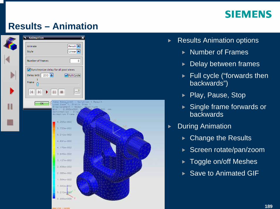
Results – AnimationResults Animation options
Number of Frames
Delay between frames
Full cycle (“forwards then backwards”)
Play, Pause, Stop
Single frame forwards or backwards
During Animation
Change the Results
Screen rotate/pan/zoom
Toggle on/off Meshes
Save to Animated GIF
190
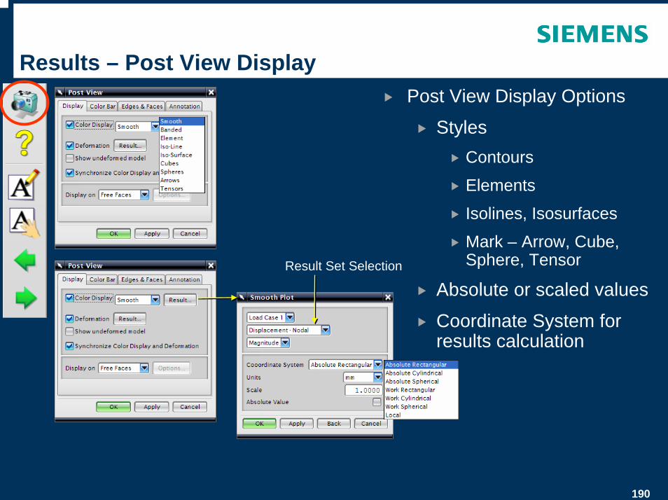
Results – Post View DisplayPost View Display Options
StylesContours
Elements
Isolines, Isosurfaces
Mark – Arrow, Cube, Sphere, Tensor
Absolute or scaled values
Coordinate System for results calculation
Result Set Selection
191
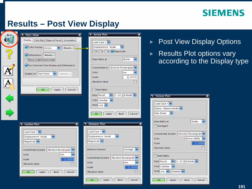
Results – Post View Display
Post View Display Options
Results Plot options vary according to the Display type
192
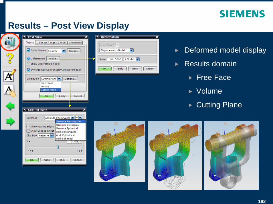
Results – Post View Display
Deformed model display
Results domain
Free Face
Volume
Cutting Plane
193
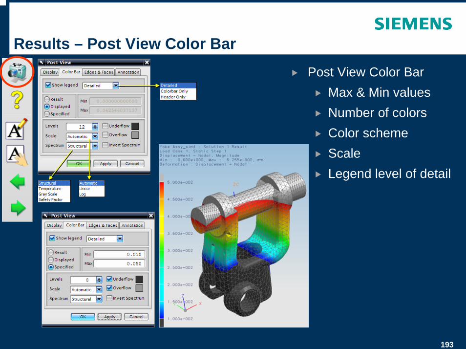
Results – Post View Color Bar
Post View Color BarMax & Min valuesNumber of colorsColor schemeScaleLegend level of detail
194
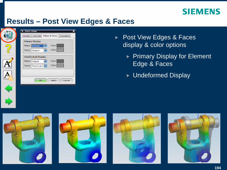
Results – Post View Edges & Faces
Post View Edges & Faces display & color options
Primary Display for Element Edge & Faces
Undeformed Display
195
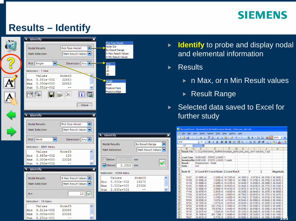
Results – IdentifyIdentify to probe and display nodal and elemental information
Results
n Max, or n Min Result values
Result Range
Selected data saved to Excel for further study
196
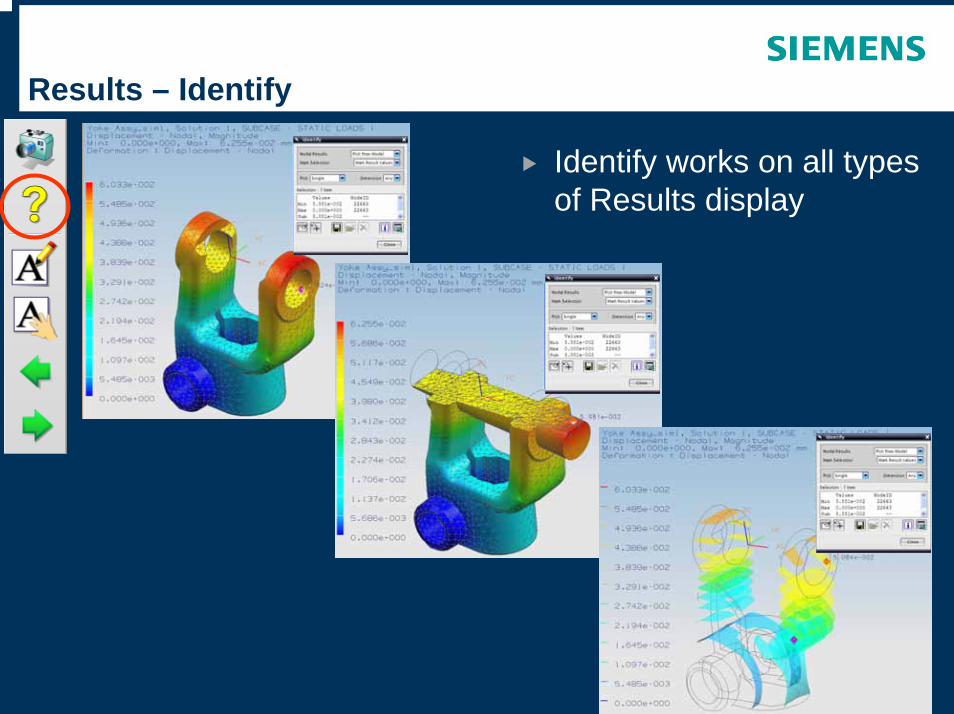
Results – Identify
Identify works on all types of Results display
197
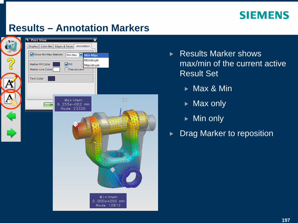
Results – Annotation Markers
Results Marker shows max/min of the current active Result Set
Max & Min
Max only
Min only
Drag Marker to reposition
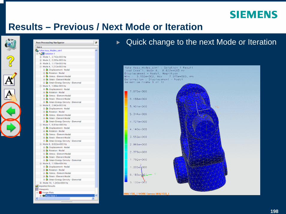
198
Results – Previous / Next Mode or IterationQuick change to the next Mode or Iteration
199
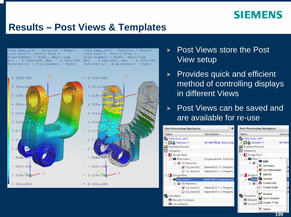
Results – Post Views & Templates
Post Views store the Post View setup
Provides quick and efficient method of controlling displays in different Views
Post Views can be saved and are available for re-use
200
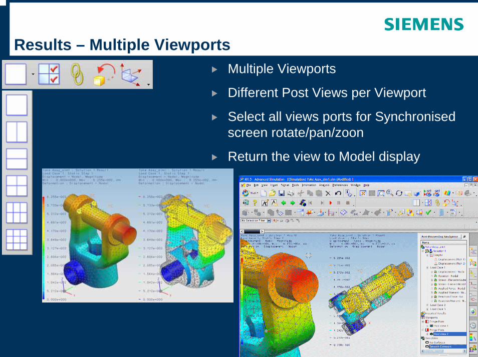
Results – Multiple ViewportsMultiple Viewports
Different Post Views per Viewport
Select all views ports for Synchronised screen rotate/pan/zoon
Return the view to Model display
201
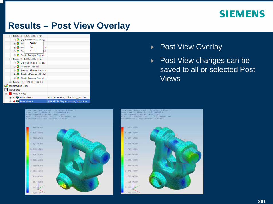
Results – Post View Overlay
Post View Overlay
Post View changes can be saved to all or selected Post Views
202
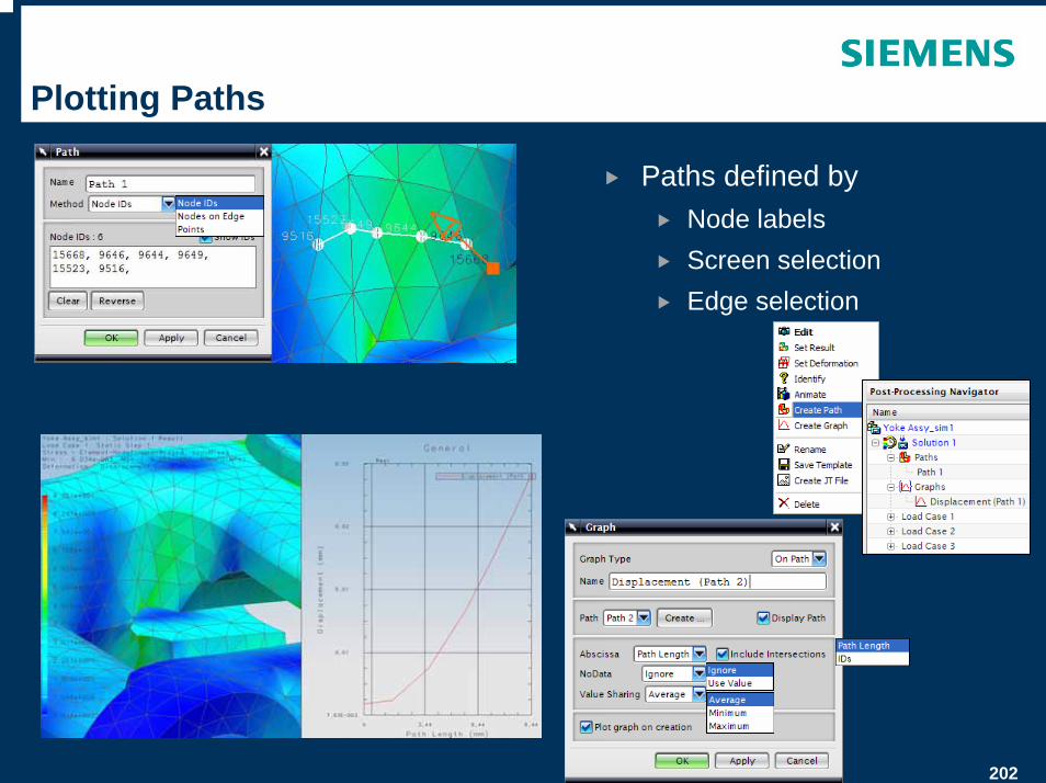
Plotting Paths
Paths defined byNode labelsScreen selectionEdge selection
203
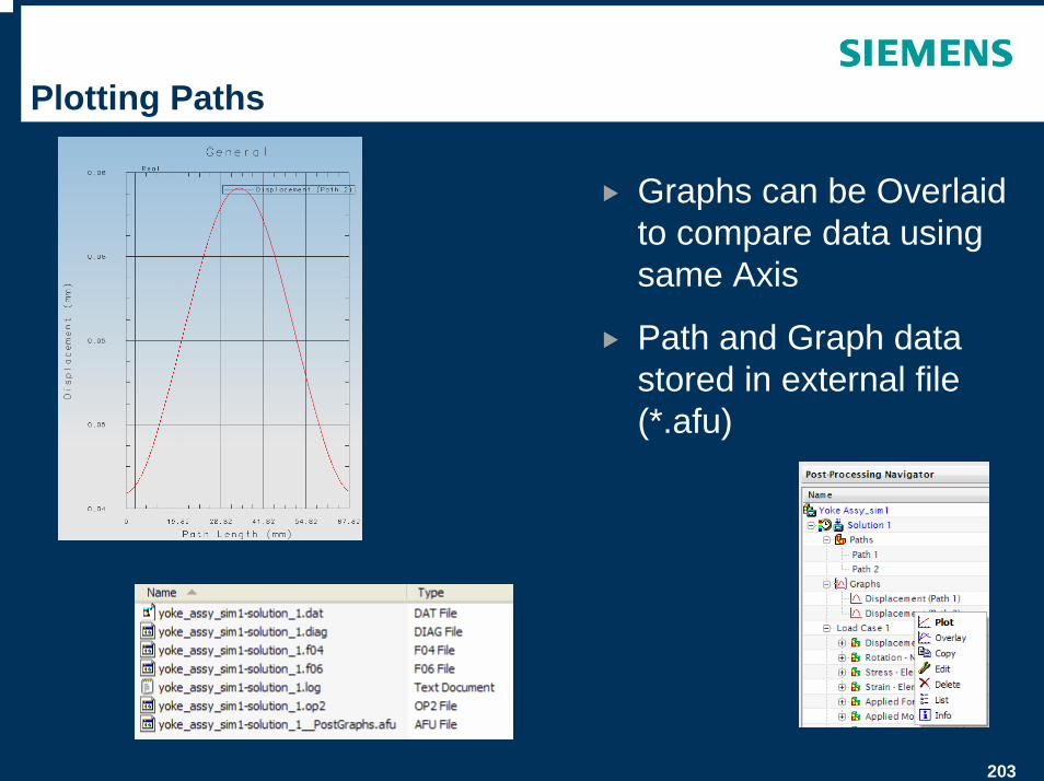
Plotting Paths
Graphs can be Overlaid to compare data using same Axis
Path and Graph data stored in external file (*.afu)
204
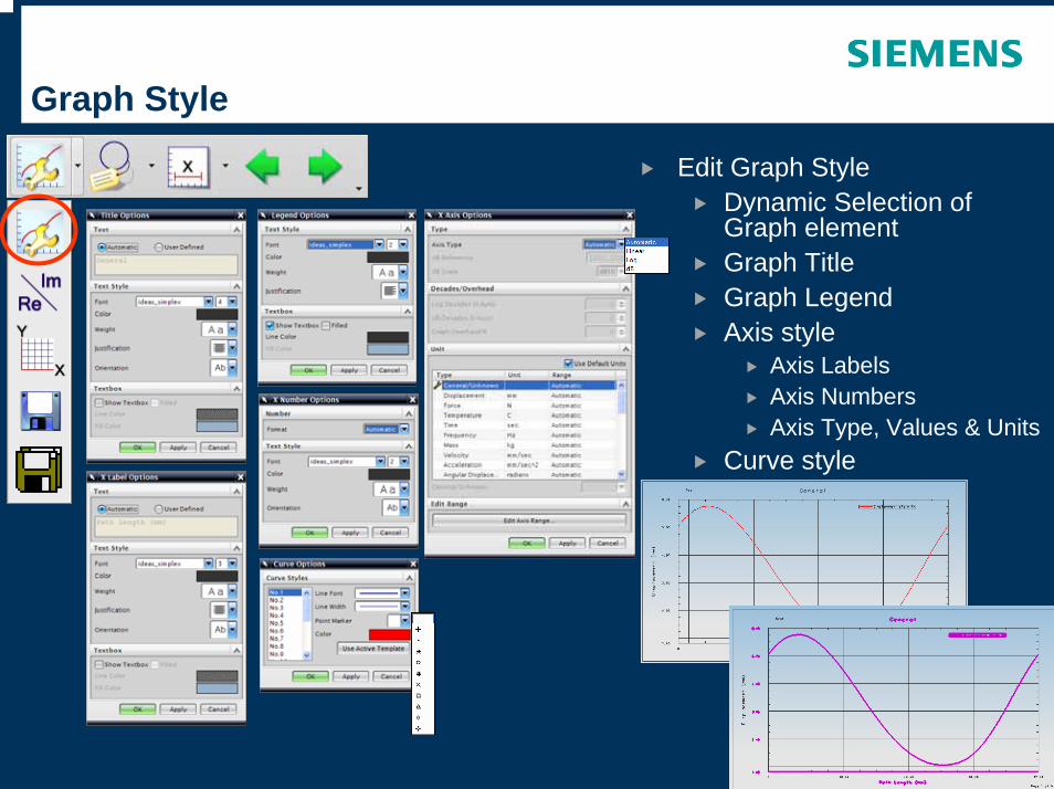
Graph Style
Edit Graph StyleDynamic Selection of Graph elementGraph TitleGraph LegendAxis style
Axis LabelsAxis NumbersAxis Type, Values & Units
Curve style
205
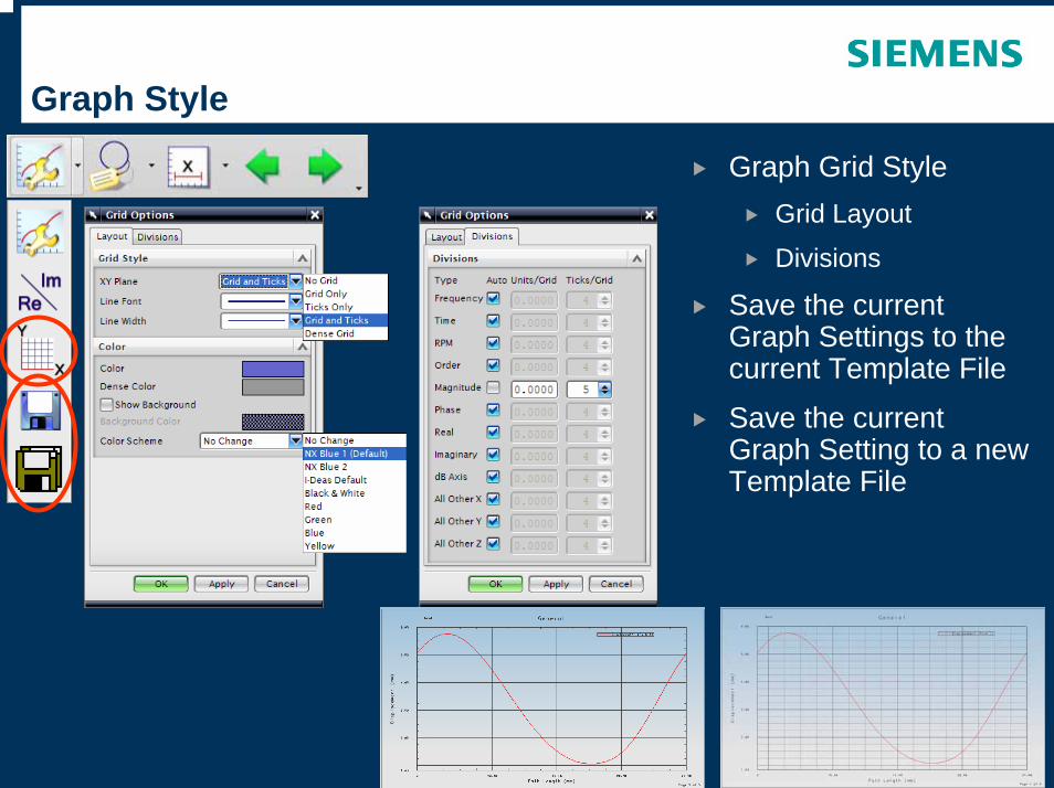
Graph Style
Graph Grid StyleGrid Layout
Divisions
Save the current Graph Settings to the current Template File
Save the current Graph Setting to a new Template File
206
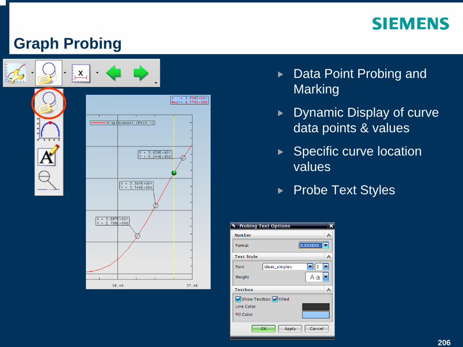
Graph Probing
Data Point Probing and Marking
Dynamic Display of curve data points & values
Specific curve location values
Probe Text Styles
207
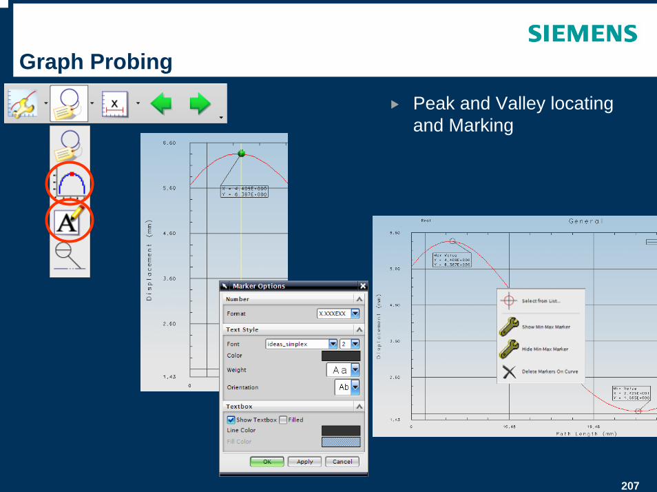
Graph Probing
Peak and Valley locating and Marking
208
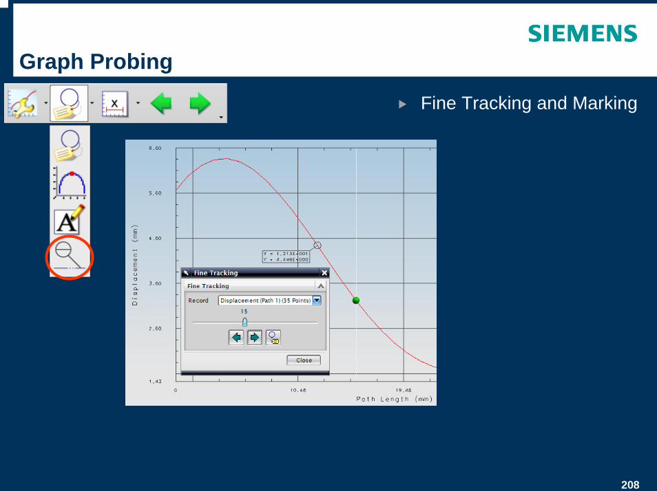
Graph Probing
Fine Tracking and Marking

209
Graph Windowing
Window into the Graph
X Window
Y Window
X-Y Window
No Window to return to full graph
210
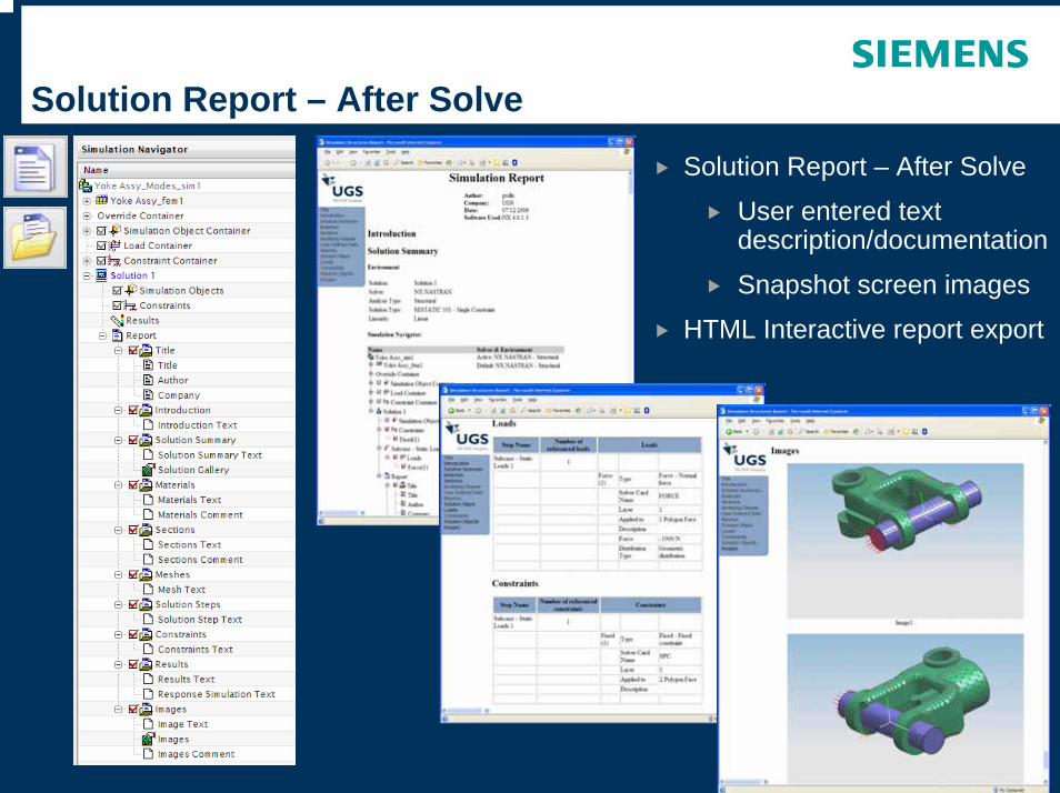
Solution Report – After Solve
Solution Report – After Solve
User entered text description/documentation
Snapshot screen images
HTML Interactive report export
211
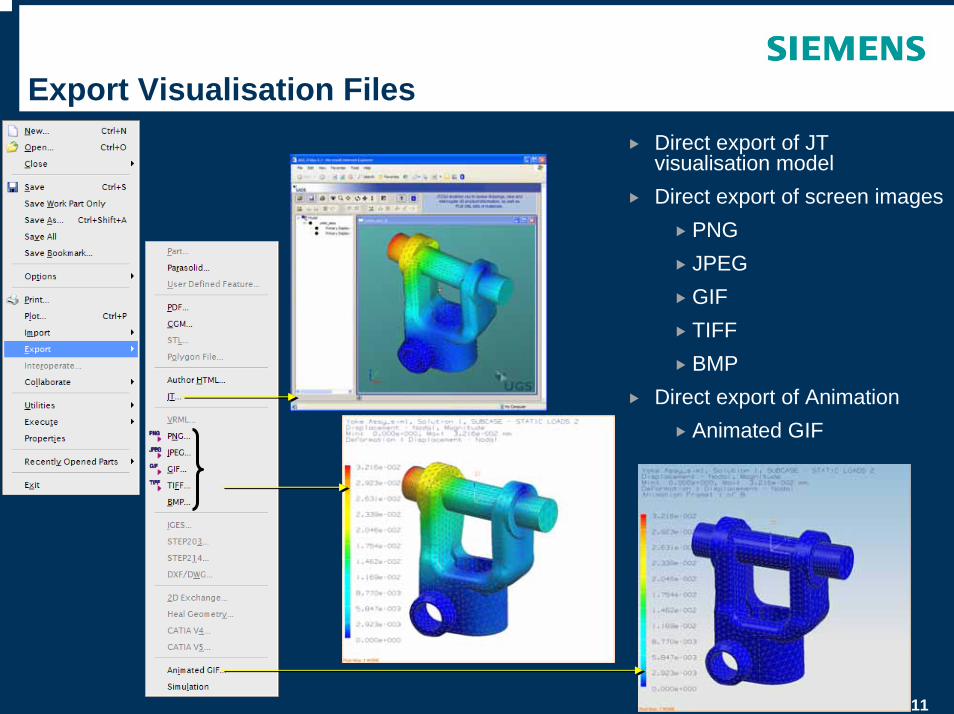
Export Visualisation FilesDirect export of JT visualisation modelDirect export of screen images
PNGJPEGGIFTIFFBMP
Direct export of AnimationAnimated GIF
© UGS Corp. 2007. All rights reserved. UGS PLM Software
Customer Defaults for Simulation
213
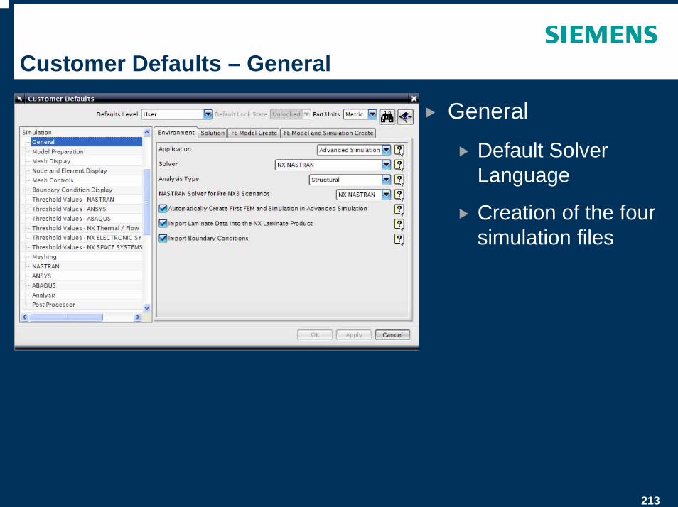
Customer Defaults – General
General
Default Solver Language
Creation of the four simulation files
214
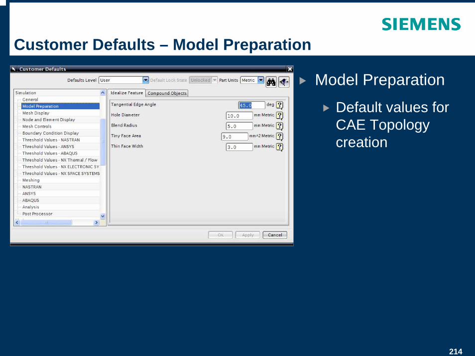
Customer Defaults – Model Preparation
Model Preparation
Default values for CAE Topology creation
215
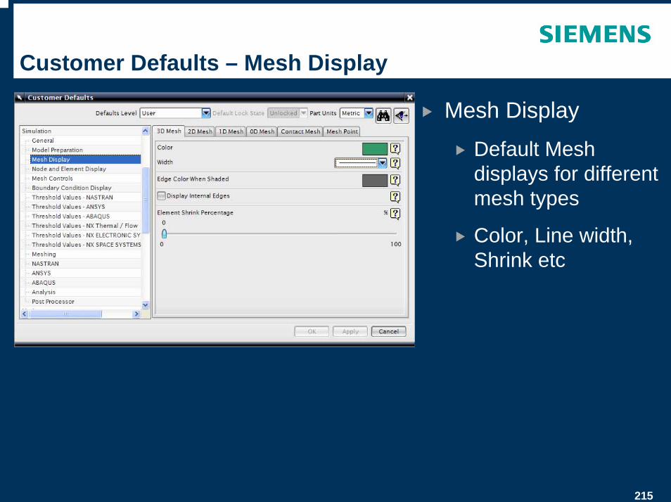
Customer Defaults – Mesh Display
Mesh Display
Default Mesh displays for different mesh types
Color, Line width, Shrink etc
216
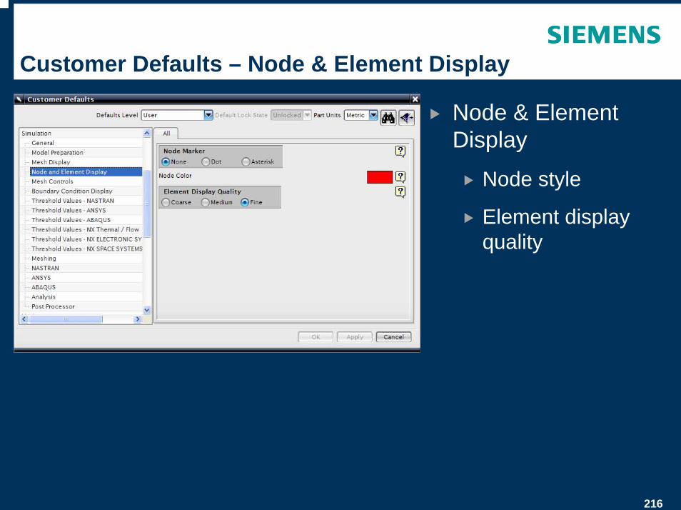
Customer Defaults – Node & Element Display
Node & Element Display
Node style
Element display quality
217
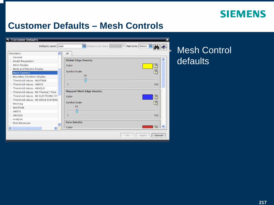
Customer Defaults – Mesh Controls
Mesh Control defaults
218
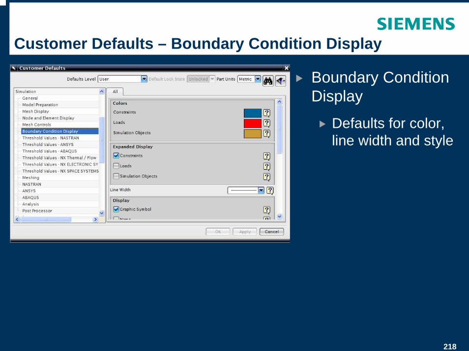
Customer Defaults – Boundary Condition Display
Boundary Condition Display
Defaults for color, line width and style
219
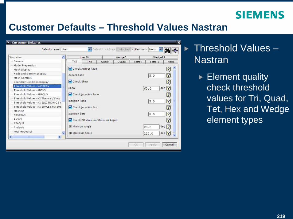
Customer Defaults – Threshold Values Nastran
Threshold Values –Nastran
Element quality check threshold values for Tri, Quad, Tet, Hex and Wedge element types
220
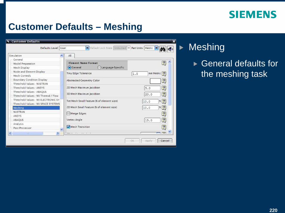
Customer Defaults – Meshing
Meshing
General defaults for the meshing task
221
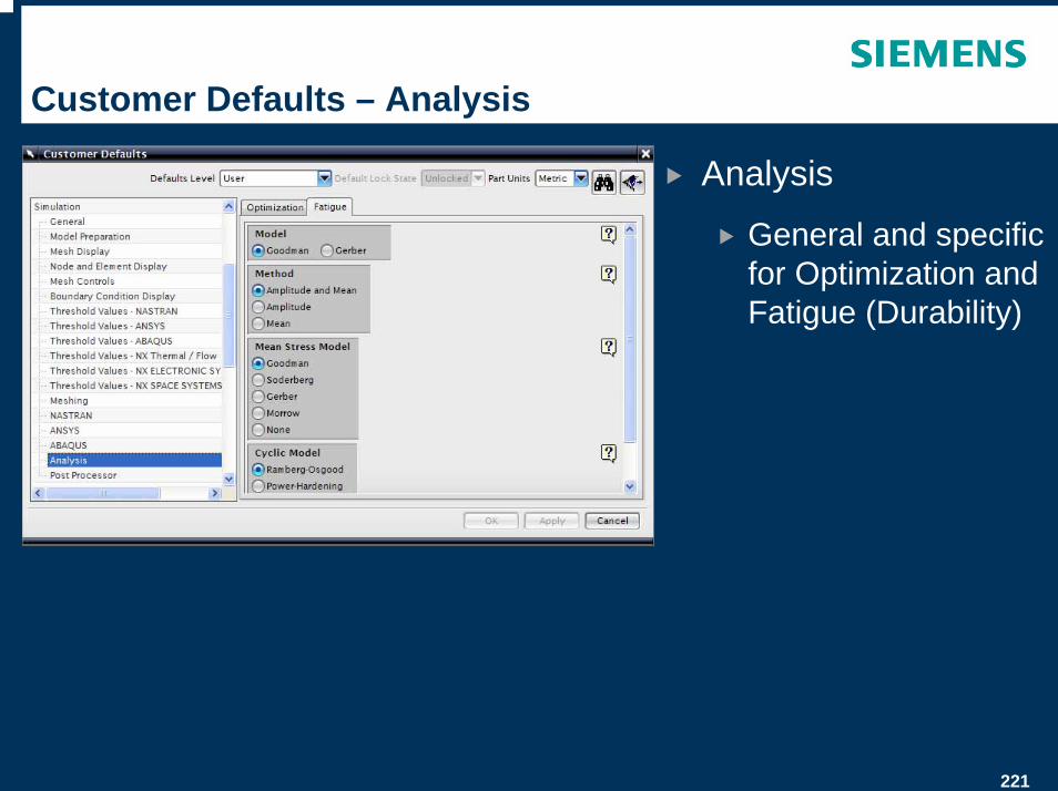
Customer Defaults – Analysis
Analysis
General and specific for Optimization and Fatigue (Durability)
222
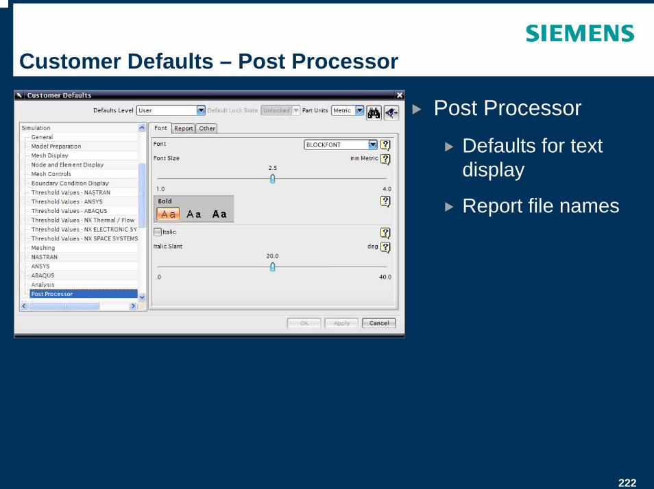
Customer Defaults – Post Processor
Post Processor
Defaults for text display
Report file names

© UGS Corp. 2007. All rights reserved. UGS PLM Software
Thank You