Embed Size (px)
Citation preview
i
Version 1.2December, 2003
VIAUser’s Manual
VIA EPIA-VMini-ITX Mainboard
P/N 99-51-012551-12
ii
CopyrightCopyright by VIA Technologies Inc. (“VIA”). No part of this manualmay be reproduced or transmitted in any form without express writtenauthorization from VIA.
TrademarksAll trademarks are the property of their respective holders.
Data protectionAll data should be backed-up prior to the installation of any drive unitor storage peripheral. VIA will not be responsible for any loss of dataresulting from the use, disuse or misuse of this or any other VIAproduct.
No WarrantyVIA has made every effort to ensure the accuracy of the content ofthis manual. However, it is possible that it may contain technicalinaccuracies or typographical or other errors. VIA will assume noliability for any inaccuracy found in this publication, nor fordamages, direct, indirect, incidental, consequential or otherwise, thatmay result from such an inaccuracy, including without limitation lossof data or profits.
VIA provides this manual “as is”, and does not issue a warranty ofany kind, express or implied, including without limitation impliedwarranties of merchantability or fitness for a particular purpose.
The information provided in this manual is subject to change withoutnotice. VIA reserves the right to alter product designs, layouts ordrivers without notification.

iii
FCC-B Radio Frequency Interference StatementThis equipment has been tested and found to comply with the limits fora class B digital device, pursuant to part 15 of the FCC rules. Theselimits are designed to provide reasonable protection against harmfulinterference when the equipment is operated in a commercialenvironment. This equipment generates, uses and can radiate radiofrequency energy and, if not installed and used in accordance withthe instruction manual, may cause harmful interference to radiocommunications. Operation of this equipment in a residential area islikely to cause harmful interference, in which case the user will berequired to correct the interference at his own expense.
Notice 1The changes or modifications not expressly approved by the party re-sponsible for compliance could void the user’s authority to operate theequipment.
Notice 2Shielded interface cables and A.C. power cord, if any, must be used inorder to comply with the emission limits.
VOIR LA NOTICE D’INSTALLATION AVANT DE RACCORDER AURESEAU.
VIA EPIA-M Mini-ITX Mainboard
Tested to comply with FCC Standard
For Home or Office Use

iv
Copyright NoticeWe take every care in the preparation of this document, but no guaran-tee is given as to the correctness of its contents. Our products areunder continual improvement and we reserve the right to make changeswithout notice.
TrademarksAll trademarks used in this manual are the property of their respectiveowners.
PS/2 and OS/2 are registered trademarks of IBM Corporation.Windows 95/98/98SE/ME/2000/NT and Windows XP are registeredtrademarks of Microsoft.Netware is a registered trademark of Novell.Award is a registered trademark of Award Software Inc.
v
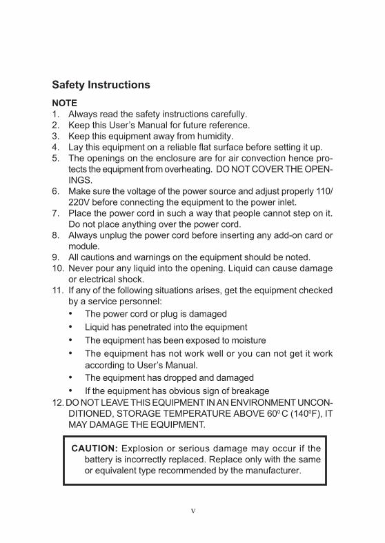
NOTE1. Always read the safety instructions carefully.2. Keep this User’s Manual for future reference.3. Keep this equipment away from humidity.4. Lay this equipment on a reliable flat surface before setting it up.5. The openings on the enclosure are for air convection hence pro-
tects the equipment from overheating. DO NOT COVER THE OPEN-INGS.
6. Make sure the voltage of the power source and adjust properly 110/220V before connecting the equipment to the power inlet.
7. Place the power cord in such a way that people cannot step on it.Do not place anything over the power cord.
8. Always unplug the power cord before inserting any add-on card ormodule.
9. All cautions and warnings on the equipment should be noted.10. Never pour any liquid into the opening. Liquid can cause damage
or electrical shock.11. If any of the following situations arises, get the equipment checked
by a service personnel:• The power cord or plug is damaged• Liquid has penetrated into the equipment• The equipment has been exposed to moisture• The equipment has not work well or you can not get it work
according to User’s Manual.• The equipment has dropped and damaged• If the equipment has obvious sign of breakage
12. DO NOT LEAVE THIS EQUIPMENT IN AN ENVIRONMENT UNCON-DITIONED, STORAGE TEMPERATURE ABOVE 600 C (1400F), ITMAY DAMAGE THE EQUIPMENT.
Safety Instructions
CAUTION: Explosion or serious damage may occur if thebattery is incorrectly replaced. Replace only with the sameor equivalent type recommended by the manufacturer.

vi
This VIA EPIA-V Mini-ITX Mainboard package should contain the follow-ing items:
• 1 x VIA EPIA-V Mini-ITX Mainboard
• 1 x User’s manual
• 1 x ATA-33/66/100 Hard drive ribbon cable
• 1 x Floppy ribbon cable
• 1 x I/O Bracket
• 1 x Driver Utilities CD
Box Contents

vi
ContentsSpecifications ......................................................... 1-1
Mainboard Specifications................................................ 1-2Mainboard Layout............................................................ 1-4Connectors Guide ............................................................ 1-5
Installation ............................................................. 2-1CPU ................................................................................. 2-2
The VIA C3™ E-Series Processor ................................... 2-2The VIA Eden Processor .................................................. 2-3
Memory Installation ......................................................... 2-4SDRAM Module Installation Procedures .......................... 2-4Available SDRAM Configurations ..................................... 2-5
Power Supply .................................................................. 2-6ATX 20-Pin Power Connector: ATXPWR ....................... 2-6
Back Panel ....................................................................... 2-7Mouse Connector: JMS1 .................................................. 2-7Keyboard Connector: JKB1 .............................................. 2-7USB Port Connectors ....................................................... 2-8RJ-45 NIC Port ................................................................. 2-8Parallel Port Connector: LPT1 ......................................... 2-8Serial Port Connector: COM 1 .......................................... 2-9S-Video Port ..................................................................... 2-9Audio Port Connectors ..................................................... 2-9RCA Video or S/PDIF Port .............................................. 2-9VGA Out ........................................................................... 2-9
Connectors ..................................................................... 2-10Hard Disk Connectors: IDE1 .......................................... 2-10Front Panel Connector (J3) ............................................. 2-11CD-ROM Line In Connector (J7) ................................... 2-11FIR Module Connector (J5) ............................................ 2-12PS2 Connector (J6) ........................................................ 2-12Wake On Modem Connector (J8) ................................... 2-13USB Port 2&3 Connector (F_USB) ............................... 2-13
vii
Video In Connector (J12) ................................................ 2-14Floppy Disk Drive Connector: FDD ............................... 2-14
Jumpers.......................................................................... 2-15Clear CMOS Jumper: CLEAR_CMOS ........................... 2-15Host Frequency Select (J13) ........................................... 2-16Auto Reboot Function Setting (J2) .................................. 2-17RCA Video or S/PDIF Select (J11) ................................. 2-17
Slots............................................................................... 2-18PCI Slots ......................................................................... 2-18PCI Interrupt Request Routing ....................................... 2-19
BIOS Setup............................................................ 3-1Entering Setup.................................................................. 3-2Control Keys.................................................................... 3-2Getting Help .................................................................... 3-3The Main Menu................................................................ 3-4Standard CMOS Features ................................................ 3-6Advanced BIOS Features ................................................ 3-8Advanced Chipset Features ........................................... 3-11Integrated Peripherals .................................................... 3-13Power Management Setup.............................................. 3-16PNP/PCI Configurations ................................................ 3-21PC Health Status ............................................................ 3-23Frequency/Voltage Control ............................................ 3-24Load Fail-Safe Defaults................................................. 3-25Load Optimized Defaults ............................................... 3-26Set Supervisor/User Password ...................................... 3-27Save & Exit Setup.......................................................... 3-29Exit Without Saving ....................................................... 3-30

viii
Software Setup...................................................... 4-1Driver Utilities CD Content ............................................. 4-2Getting Started ................................................................. 4-2Running the Driver Utilities CD ..................................... 4-2CD Content ...................................................................... 4-2
Specifications
1-1
The ultra-compact and highly intergrated VIAEPIA-V Mini-ITX Mainboard is the smallest form factormainboard specification available today, developed by VIATechnologies, Inc as part of the company’s open industry-wide Total Connectivity initiative. The VIA EPIA-V Mini-ITX mainboard enables the creation of an exciting newgeneration of small, ergonomic, innovative and affordableembedded systems. Through high level of integration,mini-ITX only occupy 66% of the size of FlexATXmainboard form factor. The mainboard comes with anembedded VIA Processor, boasting ultra low powerconsumption and cool, quiet operation.
This chapter includes the following sections:
Mainboard Specifications 1-2Mainboard Layout 1-4Components Guide 1-5
1Specifications
Chapter 1
1-2
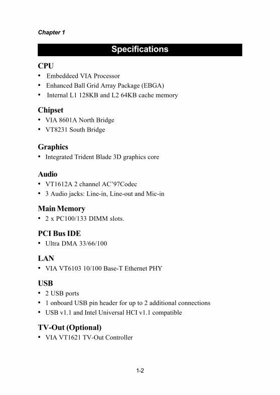
CPU• Embeddeed VIA Processor• Enhanced Ball Grid Array Package (EBGA)• Internal L1 128KB and L2 64KB cache memory
Chipset• VIA 8601A North Bridge• VT8231 South Bridge
Graphics• Integrated Trident Blade 3D graphics core
Audio• VT1612A 2 channel AC’97Codec• 3 Audio jacks: Line-in, Line-out and Mic-in
Main Memory• 2 x PC100/133 DIMM slots.
PCI Bus IDE• Ultra DMA 33/66/100
LAN• VIA VT6103 10/100 Base-T Ethernet PHY
USB• 2 USB ports• 1 onboard USB pin header for up to 2 additional connections• USB v1.1 and Intel Universal HCI v1.1 compatible
TV-Out (Optional)• VIA VT1621 TV-Out Controller
Specifications

Specifications
1-3
Onboard I/O Connectors• 1 USB connector for 2 USB 1.1 ports• CD Audio-in connector• FIR connector• PS2 connector• Wake-on-Modem• CPU/Sys FAN
Back Panel I/O• 1 PS2 mouse port• 1 PS2 keyboard port• 1 Parallel• 1 RJ45 LAN port• 1 Serial port• 2 USB 1.1 ports• 1 VGA port• 1 RCA port (S/PDIF or TV out)• 1 S-Video port
Power• Supports ATX type power supply
Onboard Floppy• 1 FDD connector
BIOS• Award BIOS• 2/4Mbit flash memory
Form Factor• Mini-ITX (4 layers)• 17 cm x 17 cm

Chapter 1
1-4
VIA EPIA-V Mini-ITX Mainboard
Layout
MicIn
LineIn
LineOut
COM Port
USB 0
USB 1
LANRJ45
RCAVideoorS/PDIF
S-Video
LPT Connector
CRT Connector
PS / 2
Keyboard
Mouse
FAN 1
FAN 2
VT1621
VT1612A
VT6103J7CD-ROM Line-In
J11RCA VideoS/PDIF
J12Video In Connector
Processor EBGA
LAN
TV Out
North Bridge VT8601A
South Bridge VT8231
ClockGenerator J13
Host Frequency SelectJ5FIR Module Connector
J2 Auto RebootFunction Setting
J3Front Panel Jumper
BIOSROM
IDE 1
FDD ATX Power Connector
DIMM 1
DIMM 2
Battery CR2032
J10Clear CMOS
J8Wake up On Modem
PS2 ConnectorJ6
Buzzer
F_USB
Specifications
1-5
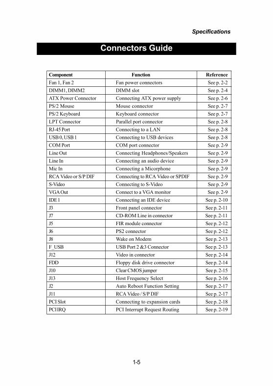
Component Function ReferenceFan 1, Fan 2 Fan power connectors See p. 2-2DIMM1, DIMM2 DIMM slot See p. 2-4ATX Power Connector Connecting ATX power supply See p. 2-6PS/2 Mouse Mouse connector See p. 2-7PS/2 Keyboard Keyboard connector See p. 2-7LPT Connector Parallel port connector See p. 2-8RJ-45 Port Connecting to a LAN See p. 2-8USB 0, USB 1 Connecting to USB devices See p. 2-8COM Port COM port connector See p. 2-9Line Out Connecting Headphones/Speakers See p. 2-9Line In Connecting an audio device See p. 2-9Mic In Connecting a Micorphone See p. 2-9RCA Video or S/P DIF Connecting to RCA Video or SPDIF See p. 2-9S-Video Connecting to S-Video See p. 2-9VGA Out Connect to a VGA monitor See p. 2-9IDE 1 Connecting an IDE device See p. 2-10J3 Front panel connector See p. 2-11J7 CD-ROM Line in connector See p. 2-11J5 FIR module connector See p. 2-12J6 PS2 connector See p. 2-12J8 Wake on Modem See p. 2-13F_USB USB Port 2 &3 Connector See p. 2-13J12 Video in connector See p. 2-14FDD Floppy disk drive connector See p. 2-14J10 Clear CMOS jumper See p. 2-15J13 Host Frequency Select See p. 2-16J2 Auto Reboot Function Setting See p. 2-17J11 RCA Video / S/P DIF See p. 2-17PCI Slot Connecting to expansion cards See p. 2-18PCI IRQ PCI Interrupt Request Routing See p. 2-19
Connectors Guide

Hardware Setup
2-1
This chapter provides you with the informationabout hardware setup procedures. While installating,please be careful in holding the components and followthe installation procedures. Some components could bedamaged if they are installed incorrectly. If possible,use a grounded wrist strap before handling computercomponents. The components can be damaged by staticelectricity.
This chapter contains the following topics:
Central Processing Unit (CPU) 2-2Memory Installation 2-4Power Supply 2-6Back Panel 2-7Connectors 2-10Jumpers 2-15Slots 2-18PCI Interrupt Request Routing 2-19
2Installation
Chapter 2
2-2
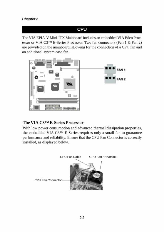
The VIA EPIA-V Mini-ITX Mainboard includes an embedded VIA Eden Proc-essor or VIA C3™ E-Series Processor. Two fan connectors (Fan 1 & Fan 2)are provided on the mainboard, allowing for the connection of a CPU fan andan additional system case fan.
CPU
CPU Fan Cable CPU Fan / Heatsink
CPU Fan Connector
The VIA C3™ E-Series ProcessorWith low power consumption and advanced thermal dissipation properties,the embedded VIA C3™ E-Series requires only a small fan to guaranteeperformance and reliability. Ensure that the CPU Fan Connector is correctlyinstalled, as displayed below.
Hardware Setup
2-3
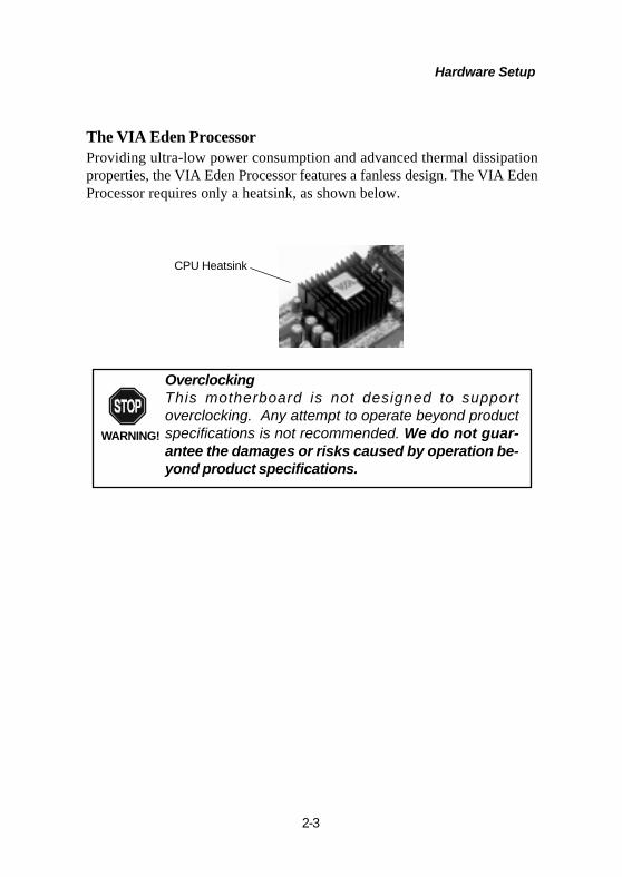
CPU Heatsink
OverclockingThis motherboard is not designed to supportoverclocking. Any attempt to operate beyond productspecifications is not recommended. We do not guar-antee the damages or risks caused by operation be-yond product specifications.
WARNING!
The VIA Eden ProcessorProviding ultra-low power consumption and advanced thermal dissipationproperties, the VIA Eden Processor features a fanless design. The VIA EdenProcessor requires only a heatsink, as shown below.

Chapter 2
2-4
The VIA EPIA-V Mini-ITX Mainboard provides two 168-pin DIMM slotsfor PC 100/133 SDRAM memory modules. To operate properly, at least onemodule must be installed.
Memory Installation
DIMM 1 & DIMM 2
SDRAM Module Installation Procedures1.) Push the white retaining latches at either end of the DIMM slot outwards.
2.) Align the SDRAM module with the corresponding notches on the DIMMslot. The modules will only fit if placed in the correct position.
2.) With both hands, press the SDRAM module down into the DIMM slot sothat the white retaining latches rotate up and secure the module in place (seepicture below).

Hardware Setup
2-5
Socket Memory Module Total Memory
DIMM 1 32MB, 64MB, 128MB, 256MB, 512MB
32MB~512MB
DIMM 2 32MB, 64MB, 128MB, 256MB, 512MB
32MB~512MB
Maximum System Memory Supported 1GB
Available SDRAM ConfigurationsRefer to the table below for available SDRAM configurations on the VIAEPIA-V Mini-ITX Mainboard.

Chapter 2
2-6
ATX 20-Pin Power ConnectorTo connect the ATX power supply, make sure the plugs of the power supplyare inserted in the proper orientation and the pins are correctly aligned. Then,push down the power supply plug firmly into the connector.
The VIA EPIA-V Mini-ITX Mainboard requires an ATX power supply to beconnected. Before inserting the power supply connector, always make surethat all components are installed correctly to ensure that no damage will becaused.
Power Supply
PIN SIGNAL11 3.3V12 -12V13 GND14 PS_ON15 GND16 GND17 GND18 NC19 5V20 5V
PIN SIGNAL1 3.3V2 3.3V3 GND4 5V5 GND6 5V7 GND8 PW_OK9 5V_SB10 12V
ATXPWR Pin Definition
1 10
2011

Hardware Setup
2-7
COM Port
LineOut
LineIn
MicIn
PS/2 Keyboard
PS/2 Mouse
USB Ports
RJ-45 Port
Back Panel
The back panel of the VIA EPIA-V Mini-ITX Mainboard contains the follow-ing connectors:
LPT Connector
CRT ConnectorS-Video Port
RCA Videoor
S / P DIF Port(Audio
Connectors)
Keyboard Connector: JKB1The mainboard provides a standard PS/2 keyboard connector for attaching aPS/2 keyboard. You can plug a PS/2keyboard directly into this connector.
Mouse Connector: JMS1The mainboard provides a standardPS/2 mouse connector for attachinga PS/2 mouse. You can plug a PS/2mouse directly into this connector.The connector location and pin as-signments are as follows:
PS/2 Mouse (6-pin Female)
2 1
34
56
PS/2 Keyboard (6-pin Female)
2 1
34
56
Pin Definition Pin DefinitionPIN SIGNAL DESCRIPTION 1 Mouse DATA Mouse DATA 2 NC No connection 3 GND Ground 4 VCC +5V 5. Mouse Clock Mouse clock 6. NC No connection
PIN SIGNAL DESCRIPTION1 Keyboard DATA Keyboard DATA2 NC No connection3 GND Ground4 VCC +5V5. Keyboard Clock Keyboard Clock6. NC No connection

Chapter 2
2-8
USB Port ConnectorsThe mainboard provides 2 USB 1.1 ports (plus 1 pin-headers for up to 2additional USB connections). USB-compatible devices can be plugged di-rectly into these ports.
Parallel Port Connector: LPT1The mainboard provides a 25-pin female connector for LPT (parallel port).A parallel port is a standard printer port that supports Enhanced Parallel Port(EPP) and Extended Capabilities Parallel Port (ECP) modes.
PIN SIGNAL DESCRIPTION1 STROBE Strobe2 DATA0 Data03 DATA1 Data14 DATA2 Data25 DATA3 Data36 DATA4 Data47 DATA5 Data58 DATA6 Data69 DATA7 Data710 ACK# Acknowledge11 BUSY Busy12 PE Paper End13 SELECT Select14 AUTO FEED# Automatic Feed15 ERR# Error16 INIT# Initialize Printer17 SLIN# Select In18 GND Ground19 GND Ground20 GND Ground21 GND Ground22 GND Ground23 GND Ground24 GND Ground25 GND Ground
Pin Definition
USB Ports
1 2 3 4
5 6 7 8
13 1
1425
RJ-45 NIC PortThe mainboard provides one standard RJ-45 port for connection to the Local AreaNetwork (LAN). You can connect a networkcable to the LAN port.
Pin DefinitionPIN SIGNAL DESCRIPTION1 VCC +5V2 -Data 0 Negative Data Channel 03 +Data 0 Positive Data Channel 04 GND Ground5. VCC +5V6. -Data 1 Negative Data Channel 17. +Data 1 Positive Data Channel 18. GND Ground

Hardware Setup
2-9
Serial Port Connectors: COM 1The mainboard offers one 9-pin male Serial Port connector (COM 1) . Youcan attach a serial mouse or other serial devices directly to this port.
S-Video PortThis port allows S-Video output inNTSC and PAL modes.
Pin Definition
Audio Port ConnectorsLine-Out is a connector for speakersor headphones. The Line-In connec-tor can be used for an external CDplayer, tape player, or other audiodevices. The Mic-In connector is forconnecting microphones.
VGA OutA DB-15 pin female connector thatconnects to a VGA monitor.
RCA Video or S/PDIF PortThis dual function port may be used ei-ther as a RCA Video port or as a S/PDIF port.
1 2 3 4 5
6 7 8 9
9-Pin Male DIN Connectors
PIN SIGNAL DESCRIPTION1 DCD Data Carry Detect2 SIN Serial In or Receive Data3 SOUT Serial Out or Transmit Data4 DTR Data Terminal Ready5. GND Ground6. DSR Data Set Ready7. RTS Request To Send8. CTS Clear To Send9. RI Ring Indicate
1/8” Stereo Audio Connectors
Line Out Line In MIC(2 Channel)

Chapter 2
2-10
IDE 1
Connectors
The VIA EPIA-V Mini-ITX Mainboard provides the following connectors:
Hard Disk Connectors: IDE1The mainboard has a 32-bit Enhanced PCI IDE and Ultra DMA 33/66/100controller that provides PIO mode 0~4, Bus Master, and Ultra DMA 33/66/100 functions. You can connect up to two hard disk drives, CD-ROM, LS-120 and other devices. These connectors utilize the provided IDE hard diskcable.
TIP: If you install two hard disks on cable, you mustconfigure the second drive to Slave mode by setting its jumper.Refer to the hard disk documentation supplied by hard diskvendors for jumper setting instructions.
IDE1 (Primary IDE Connector)The first hard drive should always be connected to IDE1. IDE1 canconnect a Master and a Slave drive.
Hardware Setup
2-11
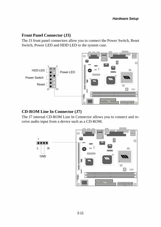
Front Panel Connector (J3)The J3 front panel connectors allow you to connect the Power Switch, ResetSwitch, Power LED and HDD LED to the system case.
1211
1 2
HDD LED
Power Switch
Reset
Power LED
L R
1
CD-ROM Line In Connector (J7)The J7 internal CD-ROM Line In Connector allows you to connect and re-ceive audio input from a device such as a CD-ROM.
GND
Chapter 2
2-12
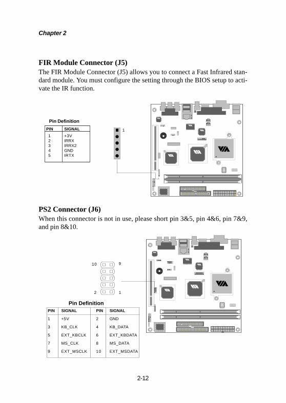
FIR Module Connector (J5)The FIR Module Connector (J5) allows you to connect a Fast Infrared stan-dard module. You must configure the setting through the BIOS setup to acti-vate the IR function.
PS2 Connector (J6)When this connector is not in use, please short pin 3&5, pin 4&6, pin 7&9,and pin 8&10.
1
1
PIN SIGNAL 1 +3V 2 IRRX 3 IRRX2 4 GND 5 IRTX
Pin Definition
PIN SIGNAL PIN SIGNAL
1 +5V 2 GND
3 KB_CLK 4 KB_DATA
5 EXT_KBCLK 6 EXT_KBDATA
7 MS_CLK 8 MS_DATA
9 EXT_MSCLK 10 EXT_MSDATA
2
10 9
Pin Definition

Hardware Setup
2-13
1
1
Wake On Modem Connector (J8)This connector (J8) allows you to connect to a modem with the Wake OnModem function. The connector will power up the system when a signal isreceived through the modem.
USB Port 2&3 Connector (F_USB)This connector allows you to connect an additional two Universal Serial Bus(USB) ports, in case the two USB ports on the back panel are not sufficient.To utilize the additional two USB connections, please plug the USB 2-portmodule onto this pin-header.
2
9
10
PIN SIGNAL PIN SIGNAL
1 VCC 2 VCC
3 USB2- 4 USB3-
5 USB2+ 6 USB3+
7 GND 8 GND
9 NC 10 GND
F_USB Pin Definition
+5V_SBGND
WOM
Chapter 2
2-14
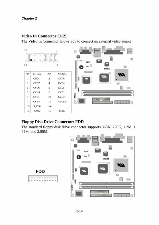
Video In Connector (J12)The Video In Connector allows you to connect an external video source.
PIN SIGNAL PIN SIGNAL
1
3
5
7
9
11
13
15
GND
CVD7
CVD6
CVHS
CVD1
CVVS
A_D30
-GNT2
2
4
6
8
10
12
14
16
CVD0
CVD4
CVD5
CVD2
CVD3
CVCLK
-REQ2
1
16 2
15
Floppy Disk Drive Connector: FDDThe standard floppy disk drive connector supports 360K, 720K, 1.2M, 1.44M, and 2.88M.
FDD
Hardware Setup
2-15
Clear CMOS
3
1
Normal
3
1
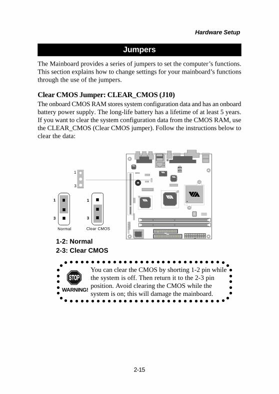
Jumpers
1-2: Normal2-3: Clear CMOS
1
3
The Mainboard provides a series of jumpers to set the computer’s functions.This section explains how to change settings for your mainboard’s functionsthrough the use of the jumpers.
Clear CMOS Jumper: CLEAR_CMOS (J10)The onboard CMOS RAM stores system configuration data and has an onboardbattery power supply. The long-life battery has a lifetime of at least 5 years.If you want to clear the system configuration data from the CMOS RAM, usethe CLEAR_CMOS (Clear CMOS jumper). Follow the instructions below toclear the data:
You can clear the CMOS by shorting 1-2 pin whilethe system is off. Then return it to the 2-3 pinposition. Avoid clearing the CMOS while thesystem is on; this will damage the mainboard.WARNING!
Chapter 2
2-16
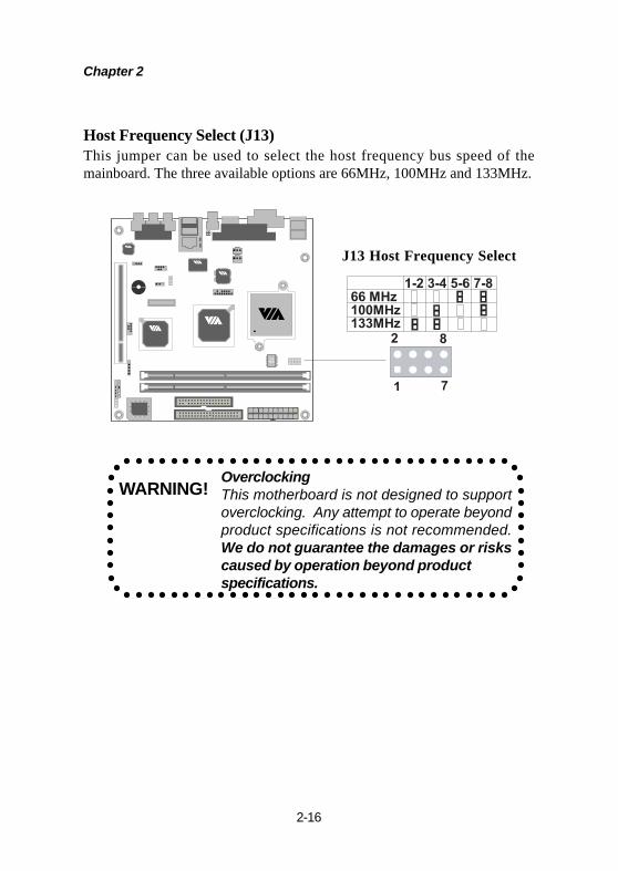
Host Frequency Select (J13)This jumper can be used to select the host frequency bus speed of themainboard. The three available options are 66MHz, 100MHz and 133MHz.
J13 Host Frequency Select
OverclockingThis motherboard is not designed to supportoverclocking. Any attempt to operate beyondproduct specifications is not recommended.We do not guarantee the damages or riskscaused by operation beyond productspecifications.
WARNING!
Hardware Setup
2-17
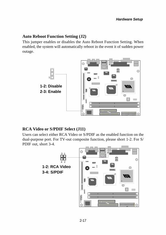
1
1-2: Disable2-3: Enable
Auto Reboot Function Setting (J2)This jumper enables or disables the Auto Reboot Function Setting. Whenenabled, the system will automatically reboot in the event it of sudden poweroutage.
1-2: RCA Video3-4: S/PDIF
RCA Video or S/PDIF Select (J11)Users can select either RCA Video or S/PDIF as the enabled function on thedual-purpose port. For TV-out composite function, please short 1-2. For S/PDIF out, short 3-4.
13
24

Chapter 2
2-18
Slots
PCI SlotThe PCI slot allows you to insert PCI expansion card. When adding or re-moving expansion cards, make sure that you unplug the power supply first.Meanwhile, read the documentation for the expansion card to make any nec-essary hardware or software settings for the expansion card, such as jumpers,switches or BIOS configuration.
Hardware Setup
2-19
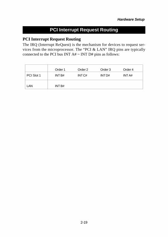
PCI Interrupt Request RoutingThe IRQ (Interrupt ReQuest) is the mechanism for devices to request ser-vices from the microprocessor. The “PCI & LAN” IRQ pins are typicallyconnected to the PCI bus INT A# ~ INT D# pins as follows:
Order 1 Order 2 Order 3 Order 4
PCI Slot 1 INT B# INT C# INT D# INT A#
LAN INT B#
PCI Interrupt Request Routing

BIOS Setup
3-1
3BIOS Setup
This chapter gives you detailed explaination of BIOS setupfunctions. It consists of the following topics:
Entering Setup 3-2Control Keys 3-2Getting Help 3-3The Main Menu 3-4Standard CMOS Features 3-6Advanced BIOS Features 3-8Advanced Chipset Features 3-11Integrated Peripherals 3-13Power Management Setup 3-16PNP/PCI Configurations 3-21PC Health Status 3-23Frequency/Voltage Control 3-24Load Fail-Safe Defaults 3-25Load Optimized Defaults 3-26Set Supervisor/User Password 3-27Save & Exit Setup 3-29Exit Without Saving 3-30
Chapter 3
3-2
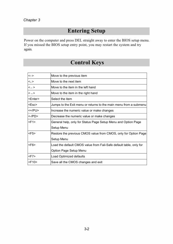
Entering SetupPower on the computer and press DEL straight away to enter the BIOS setup menu.If you missed the BIOS setup entry point, you may restart the system and tryagain.
Control Keys
<↑> Move to the previous item
<↓> Move to the next item
<←> Move to the item in the left hand
<→> Move to the item in the right hand
<Enter> Select the item
<Esc> Jumps to the Exit menu or returns to the main menu from a submenu
<+/PU> Increase the numeric value or make changes
<-/PD> Decrease the numeric value or make changes
<F1> General help, only for Status Page Setup Menu and Option Page
Setup Menu
<F5> Restore the previous CMOS value from CMOS, only for Option Page
Setup Menu
<F6> Load the default CMOS value from Fail-Safe default table, only for
Option Page Setup Menu
<F7> Load Optimized defaults
<F10> Save all the CMOS changes and exit
BIOS Setup
3-3
Getting Help
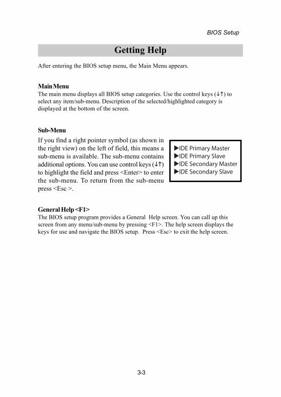
Sub-MenuIf you find a right pointer symbol (as shown inthe right view) on the left of field, this means asub-menu is available. The sub-menu containsadditional options. You can use control keys ( )to highlight the field and press <Enter> to enterthe sub-menu. To return from the sub-menupress <Esc >.
General Help <F1>The BIOS setup program provides a General Help screen. You can call up thisscreen from any menu/sub-menu by pressing <F1>. The help screen displays thekeys for use and navigate the BIOS setup. Press <Esc> to exit the help screen.
After entering the BIOS setup menu, the Main Menu appears.
Main MenuThe main menu displays all BIOS setup categories. Use the control keys ( ) toselect any item/sub-menu. Description of the selected/highlighted category isdisplayed at the bottom of the screen.
IDE Primary Master IDE Primary Slave IDE Secondary Master IDE Secondary Slave
Chapter 3
3-4
The Main Menu
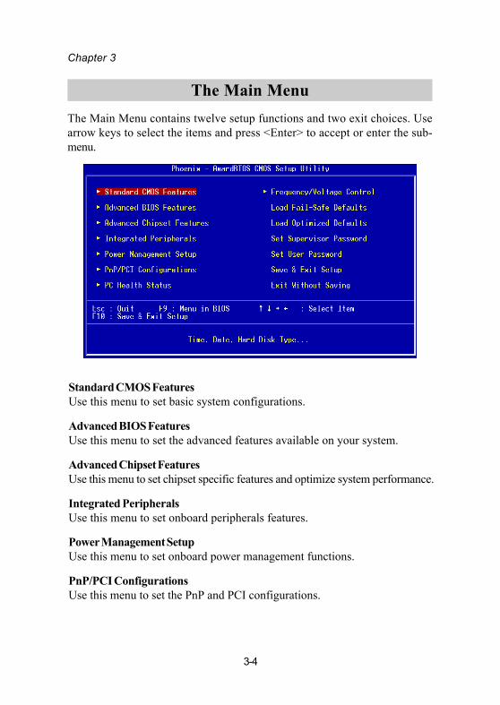
Standard CMOS FeaturesUse this menu to set basic system configurations.
Advanced BIOS FeaturesUse this menu to set the advanced features available on your system.
Advanced Chipset FeaturesUse this menu to set chipset specific features and optimize system performance.
Integrated PeripheralsUse this menu to set onboard peripherals features.
Power Management SetupUse this menu to set onboard power management functions.
PnP/PCI ConfigurationsUse this menu to set the PnP and PCI configurations.
The Main Menu contains twelve setup functions and two exit choices. Usearrow keys to select the items and press <Enter> to accept or enter the sub-menu.
BIOS Setup
3-5
PC Health StatusThis menu shows the PC health status.
Frequency/Voltage ControlUse this menu to set the system frequency and voltage control.
Load Fail-Safe DefaultsUse this menu to load the BIOS default settings for minimal and stable systemoperations.
Load Optimized DefaultsUse this menu to load BIOS default settings for optimal and high performancesystem operations.
Set Supervisor PasswordUse this menu to set supervisor password.
Set User PasswordUse this menu to set user password.
Save & Exit SetupSave BIOS setting changes and exit setup.
Exit Without SavingAbandon all BIOS setting changes and exit setup.
Chapter 3
3-6
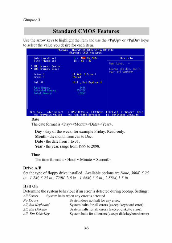
DateThe date format is <Day><Month><Date><Year>.
Day - day of the week, for example Friday. Read-only.Month - the month from Jan to Dec.Date - the date from 1 to 31.Year - the year, range from 1999 to 2098.
TimeThe time format is <Hour><Minute><Second>.
Drive A/BSet the type of floppy drive installed. Available options are None, 360K, 5.25in., 1.2M, 5.25 in., 720K, 3.5 in., 1.44M, 3.5 in., 2.88M, 3.5 in.
Halt OnDetermine the system behaviour if an error is detected during bootup. Settings:All Errors System halts when any error is detected.No Errors System does not halt for any error.All, But Keyboard System halts for all errors (except keyboard error).All, But Diskette System halts for all errors (except diskette error).All, But Disk/Key System halts for all errors (except disk/keyboard error)
Standard CMOS FeaturesUse the arrow keys to highlight the item and use the <PgUp> or <PgDn> keysto select the value you desire for each item.
BIOS Setup
3-7
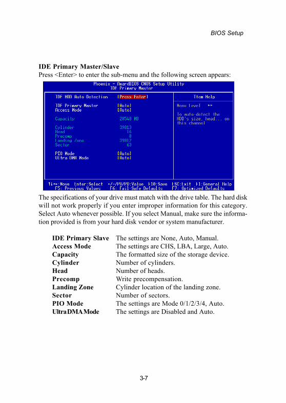
IDE Primary Master/SlavePress <Enter> to enter the sub-menu and the following screen appears:
The specifications of your drive must match with the drive table. The hard diskwill not work properly if you enter improper information for this category.Select Auto whenever possible. If you select Manual, make sure the informa-tion provided is from your hard disk vendor or system manufacturer.
IDE Primary Slave The settings are None, Auto, Manual.Access Mode The settings are CHS, LBA, Large, Auto.Capacity The formatted size of the storage device.Cylinder Number of cylinders.Head Number of heads.Precomp Write precompensation.Landing Zone Cylinder location of the landing zone.Sector Number of sectors.PIO Mode The settings are Mode 0/1/2/3/4, Auto.Ultra DMA Mode The settings are Disabled and Auto.
Chapter 3
3-8
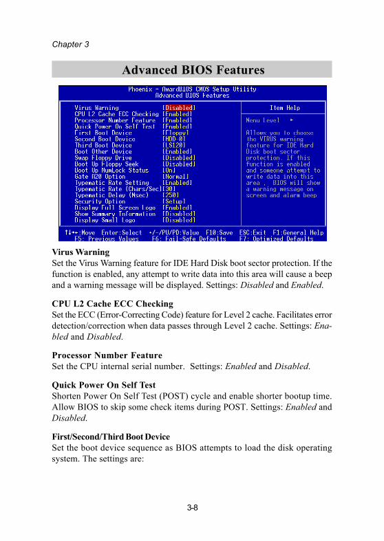
Advanced BIOS Features
Virus WarningSet the Virus Warning feature for IDE Hard Disk boot sector protection. If thefunction is enabled, any attempt to write data into this area will cause a beepand a warning message will be displayed. Settings: Disabled and Enabled.
CPU L2 Cache ECC CheckingSet the ECC (Error-Correcting Code) feature for Level 2 cache. Facilitates errordetection/correction when data passes through Level 2 cache. Settings: Ena-bled and Disabled.
Processor Number FeatureSet the CPU internal serial number. Settings: Enabled and Disabled.
Quick Power On Self TestShorten Power On Self Test (POST) cycle and enable shorter bootup time.Allow BIOS to skip some check items during POST. Settings: Enabled andDisabled.
First/Second/Third Boot DeviceSet the boot device sequence as BIOS attempts to load the disk operatingsystem. The settings are:

BIOS Setup
3-9
Floppy The system will boot from floppy drive.LS120 The system will boot from LS-120 drive.HDD-0 The system will boot from first HDD.SCSI The system will boot from SCSI.CD-ROM The system will boot from CD-ROM.HDD-1 The system will boot from second HDD.HDD-2 The system will boot from third HDD.HDD-3 The system will boot from fourth HDD.ZIP100 The system will boot from ATAPI ZIP drive.
USB-FDD The system will boot from USB floppy drive. USB-ZIP The system will boot from USB ZIP drive. USB-CDROM The system will boot from USB CDROM. USB-HDD The system will boot from USB HDD.
LAN The system will boot from network drive.Disabled Disable this sequence.
Boot Other DeviceEnable the system to boot from other devices if the system fails to boot fromthe First/Second/Third boot device. Settings: Enabled and Disabled.
Swap Floppy DriveIf the system has two floppy drives, choose enable to assign physical drive Bto logical drive A and vice-versa. Settings: Enabled and Disabled.
Boot Up Floppy SeekSet floppy seek during POST, BIOS will determine whether the floppy is 40 or80 tracks. Settings: Enabled and Disabled.
Boot Up NumLock StatusSet the NumLock status when the system is powered on. “On” will turn keypad into number keys, and “Off” will turn key pad into arrow keys. Settings: Onand Off.
Gate A20 OptionThe option, Fast, allows the chipset to control Gate A20, and the Nomal op-tion makes a pin in the keyboard controller control Gate A20. Settings: Fastand Normal.
Chapter 3
3-10
Typematic Rate SettingSet the typematic rate and delay. Settings: Enabled and Disabled.
Typematic Rate (Chars/Sec)When Typematic Rate Setting is enabled. This item allows you to set the rate(characters/second) at which the keys are accelerated. Settings: 6, 8, 10, 12,15, 20, 24 and 30.
Typematic Delay (Msec)When Typematic Rate Setting is enabled. This item allows you to select thedelay between when the key was first pressed and when the acceleration begins.Settings: 250, 500, 750 and 1000.
Security OptionSpecifies the type of BIOS password protection that is implemented. Settingsare described below:
Display Full Screen logoShow full screen logo during BIOS bootup process. Settings: Enabled andDisabled.
Show Summary InformationShow summary information during BIOS bootup process. Settings: Enabledand Disabled.
Display Small LogoShow small energy star logo during BIOS bootup process. Settings: Enabledand Disabled.
Option DescriptionSetup The password prompt appears only when end users try to
run Setup.
System A password prompt appears every time when the com-puter is powered on or when end users try to run Setup.

BIOS Setup
3-11
The Advanced Chipset Features menu is used for optimizing the chipsetfunctions.
Advanced Chipset Features
Note: Change these settings only if you are familiar with the chipset.
AGP Aperture SizeThis setting controls how much memory space can be allocated toAGP for display purposes. The aperture is a portion of the PCImemory address range dedicated to graphics memory addressspace. Host cycles that hit the aperture range are forwarded to theAGP without any translation. Settings: 4MB, 8MB, 16MB, 32MB,64MB, 128MB, and 256MB.
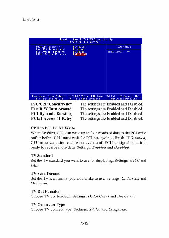
CPU & PCI Bus ControlPress <Enter> to enter the sub-menu and the screen at the nextpage would appear:
Chapter 3
3-12
CPU to PCI POST WriteWhen Enabled, CPU can write up to four words of data to the PCI writebuffer before CPU must wait for PCI bus cycle to finish. If Disabled,CPU must wait after each write cycle until PCI bus signals that it isready to receive more data. Settings: Enabled and Disabled.
TV StandardSet the TV standard you want to use for displaying. Settings: NTSC andPAL.
TV Scan FormatSet the TV scan format you would like to use. Settings: Underscan andOverscan.
TV Dot FunctionChoose TV dot function. Settings: Dedot Crawl and Dot Crawl.
TV Connector TypeChoose TV connect type. Settings: SVideo and Composite.
P2C/C2P Concurrency The settings are Enabled and Disabled.Fast R-W Turn Around The settings are Enabled and Disabled.PCI Dynamic Bursting The settings are Enabled and Disabled.PCI#2 Access #1 Retry The settings are Enabled and Disabled.

BIOS Setup
3-13
Integrated Peripherals
Onboard IDE ChannelThe integrated peripheral controller contains an IDE interface. ChooseEnabled to activate the channel. Settings: Disabled, Enabled.
IDE Prefetch ModeThis allows your hard disk controller to use the fast block mode to trans-fer data to and from the hard disk drive. Block mode is also called blocktransfer, multiple commands or multiple sector read/write. Enabled ena-bles IDE controller to use block mode; Disabled allows the controller touse standard mode.
Display Card PriorityThis setting specifies which VGA card is your primary graphics adapter.Settings: PCI Slot and AGP.
Frame Buffer SizeSet the Frame Buffer size. Settings: 16M, 32M, and 64M.

Chapter 3
3-14
AC97 AudioAuto allows the mainboard to detect whether an audio device is used. Ifthe device is detected, the onboard VIA AC’97 (Audio Codec’97) con-troller will be enabled; if not, it is disabled. Disable the controller ifyou want to use other controller cards to connect an audio device. Set-ting options: Auto and Disabled.
VIA-3043 OnChip LANDecide whether to invoke the boot ROM of VIA-3043 onchip LAN.Settings: Enabled and Disabled.
USB Keyboard SupportEnable USB Keyboard Support for DOS and Windows 95. Settings: En-abled and Disabled.
Onboard Parallel ModeSet the parallel port mode. To operate the onboard parallel port as Stand-ard Parallel Port, choose “SPP.” To operate the onboard parallel port inthe EPP mode, choose “EPP.” By choosing “ECP”, the onboard parallelport will operate in ECP mode. Choosing “ECP + EPP” will allow theonboard parallel port to support both the ECP and EPP modes simulta-neously. Settings are:Normal : Standard Parallel PortEPP : Enhanced Parallel PortECP : Extended Capability PortECP + EPP: Extended Capability Port + Enhanced Parallel Port
ECP Mode Use DMAECP utilises a DMA channel. This field is only available if Parallel PortMode is set to “ECP”. Select DMA channel for ECP use.
BIOS Setup
3-15
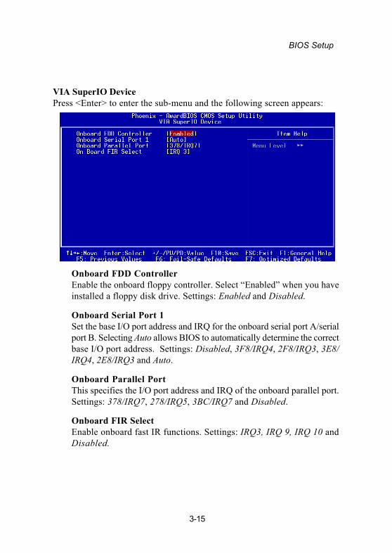
VIA SuperIO DevicePress <Enter> to enter the sub-menu and the following screen appears:
Onboard FDD ControllerEnable the onboard floppy controller. Select “Enabled” when you haveinstalled a floppy disk drive. Settings: Enabled and Disabled.
Onboard Serial Port 1Set the base I/O port address and IRQ for the onboard serial port A/serialport B. Selecting Auto allows BIOS to automatically determine the correctbase I/O port address. Settings: Disabled, 3F8/IRQ4, 2F8/IRQ3, 3E8/IRQ4, 2E8/IRQ3 and Auto.
Onboard Parallel PortThis specifies the I/O port address and IRQ of the onboard parallel port.Settings: 378/IRQ7, 278/IRQ5, 3BC/IRQ7 and Disabled.
Onboard FIR SelectEnable onboard fast IR functions. Settings: IRQ3, IRQ 9, IRQ 10 andDisabled.
Chapter 3
3-16
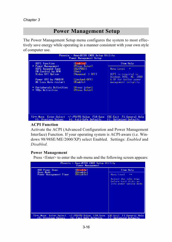
Power Management SetupThe Power Management Setup menu configures the system to most effec-tively save energy while operating in a manner consistent with your own styleof computer use.
ACPI FunctionActivate the ACPI (Advanced Configuration and Power ManagementInterface) Function. If your operating system is ACPI-aware (i.e. Win-dows 98/98SE/ME/2000/XP) select Enabled. Settings: Enabled andDisabled.
Power Management Press <Enter> to enter the sub-menu and the following screen appears:
BIOS Setup
3-17
Set the idle time before system enters power saving mode. ACPI OSsuch as Windows XP will override this option. Settings: Disable and 1/2/4/6/8/10/20/30/40 min and 1 hr.
ACPI Suspend TypeSet the power saving mode for ACPI function. Settings are:S1/POS - S1/Power On Suspend (POS) is a low power state. In this state, nosystem context (CPU or chipset) is lost and hardware maintains all system context.S3/STR - S3/Suspend To RAM (STR) is a power-down state. In this state, poweris supplied only to essential components such as main memory and wakeup-capabledevices. The system context is saved to main memory, and context is restored fromthe memory when a “wakeup” event occurs.S1 & S3 - Depends on OS to select S1 or S3.
PM Control by APMSet if you want the power management function to be controlled by APM.Settings: Yes and No.
Video Off OptionSelect whether or not to turn off the screen when system enters powersaving mode, ACPI OS such as Windows XP will override this option.Settings are:Always On - The screen is always on even when system enters powersaving mode.Suspend -> Off - The screen is turned off when system enters powersaving mode.
Power Off by PWRBTNThis field configures the power button function. Settings are:Delay 4 Sec - The system is turned off if power button is pressed for morethan four seconds.Instant-Off - The power button functions as a normal power-on/-offbutton.
AC Loss Auto RestartIf there happens to be AC power loss when your system is running, thisitem allows you to choose the power state when the AC power is back.The <Off> option keeps system in Off state until you press the powerbutton. Settings: Disable and Enable.

Chapter 3
3-18
Peripheral ActivitiesPress <Enter> to enter the sub-menu and the following screen appears:
VGA EventDecide whether or not the power management unit should monitor VGA activities.Settings: Off and ON.
LPT & COM EventDecide whether or not the power management unit should monitor parallel port(LPT) and serial port (COM) activities. Settings: None, LPT, COM and LPT/COM.
HDD & FDD EventDecide whether or not the power management unit should monitor hard disks andfloppy drives activties. Settings: Off and On.
PCI Master EventDecide whether or not the power management unit should monitor PCI masteractivties. Settings: Off and On.
PS2KB Wakeup SelectWhen Select Password, Please press ENTER key to change Password, Max 8characters. Settings: Password and Hot key.
BIOS Setup
3-19
PS2KB Wakeup from suspendSelect which “Hot-Key” is used to wake-up the system from power saving mode.Settings: Disabled, Ctrl+F1, Ctrl+F2, Ctrl+F3, Ctrl+F4, Ctrl+F5, Ctrl+F6,Ctrl+F7, Ctrl+F8, Ctrl+F9, Ctrl+F10, Ctrl+F11, Ctrl+F12, Power, Wake andAny Key.
USB ResumeDecide whether or not the USB devices can wake the system from suspend state.Settings: Disabled and Enabled.
PowerOn by PCI CardDecide whether or not a PCI card can power up the system or resume it fromsuspend state. Such PCI cards include LAN, onboard USB ports, etc. Settings:Disabled and Enabled.
Modem Ring ResumeDecide whether or not Ring-In signals from Modem can wake up the system fromsuspend state. Settings: Disabled and Enabled.
RTC Alarm ResumeThe field is used to enable or disable the feature of booting up the systemon a scheduled time/date. Settings: Disabled and Enabled.Date (of Month)The field specifies the date for RTC Alarm Resume. Settings: 0~31.Resume Time (hh:mm:ss)The field specifies the time for RTC Alarm Resume. Format is <hour><minute><second>.
Chapter 3
3-20
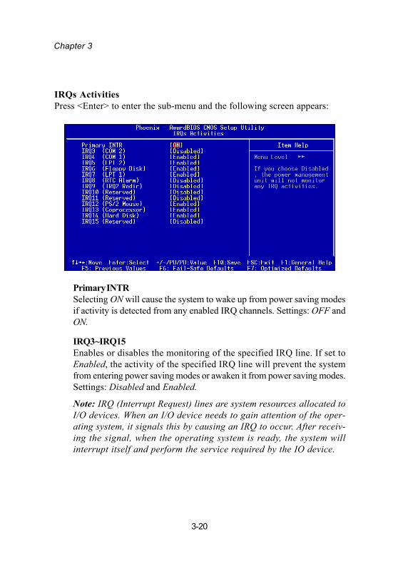
IRQs ActivitiesPress <Enter> to enter the sub-menu and the following screen appears:
Primary INTRSelecting ON will cause the system to wake up from power saving modesif activity is detected from any enabled IRQ channels. Settings: OFF andON.
IRQ3~IRQ15Enables or disables the monitoring of the specified IRQ line. If set toEnabled, the activity of the specified IRQ line will prevent the systemfrom entering power saving modes or awaken it from power saving modes.Settings: Disabled and Enabled.
Note: IRQ (Interrupt Request) lines are system resources allocated toI/O devices. When an I/O device needs to gain attention of the oper-ating system, it signals this by causing an IRQ to occur. After receiv-ing the signal, when the operating system is ready, the system willinterrupt itself and perform the service required by the IO device.
BIOS Setup
3-21
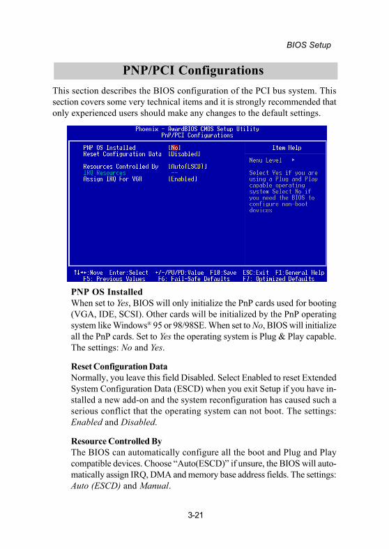
PNP/PCI ConfigurationsThis section describes the BIOS configuration of the PCI bus system. Thissection covers some very technical items and it is strongly recommended thatonly experienced users should make any changes to the default settings.
PNP OS InstalledWhen set to Yes, BIOS will only initialize the PnP cards used for booting(VGA, IDE, SCSI). Other cards will be initialized by the PnP operatingsystem like Windows® 95 or 98/98SE. When set to No, BIOS will initializeall the PnP cards. Set to Yes the operating system is Plug & Play capable.The settings: No and Yes.
Reset Configuration DataNormally, you leave this field Disabled. Select Enabled to reset ExtendedSystem Configuration Data (ESCD) when you exit Setup if you have in-stalled a new add-on and the system reconfiguration has caused such aserious conflict that the operating system can not boot. The settings:Enabled and Disabled.
Resource Controlled ByThe BIOS can automatically configure all the boot and Plug and Playcompatible devices. Choose “Auto(ESCD)” if unsure, the BIOS will auto-matically assign IRQ, DMA and memory base address fields. The settings:Auto (ESCD) and Manual.

Chapter 3
3-22
IRQ ResourcesThe items are adjustable only when Resources Controlled By is set toManual. Press <Enter> and you will enter the sub-menu of the items.
IRQ Resources list IRQ 3/4/5/7/9/10/11/12/14/15 for users to set eachIRQ a type depending on the type of device using the IRQ. Settings:PCI Device For Plug & Play compatible devices designed forPCI bus architecture.Reserved The IRQ will be reserved for further request.
Assign IRQ For VGAAssign IRQ for VGA. Settings: Disabled and Enabled.

BIOS Setup
3-23
PC Health StatusThis section shows the status of your CPU, fan, warning for overall systemstatus.
Current CPU Temp, CPU Fan Speed, System Fan Speed, +12V, +5V,+3.3V, CPU Vcore.These items display the current status of all of the monitored hardwaredevices/components such as CPU voltages, temperatures and all fans’speeds.
Chapter 3
3-24
Frequency/Voltage Control
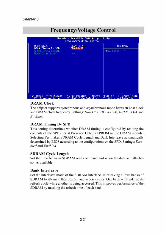
DRAM ClockThe chipset supports synchronous and asynchronous mode between host clockand DRAM clock frequency. Settings: Host CLK, HCLK-33M, HCLK+33M, andBy Auto.
DRAM Timing By SPDThis setting determines whether DRAM timing is configured by reading thecontents of the SPD (Serial Presence Detect) EPROM on the DRAM module.Selecting Yes makes SDRAM Cycle Length and Bank Interleave automaticallydetermined by BIOS according to the configurations on the SPD. Settings: Disa-bled and Enabled.
SDRAM Cycle LengthSet the time between SDRAM read command and when the data actually be-comes available.
Bank InterleaveSet the interleave mode of the SDRAM interface. Interleaving allows banks ofSDRAM to alternate their refresh and access cycles. One bank will undergo itsrefresh cycle while another is being accessed. This improves performance of theSDRAM by masking the refresh time of each bank.
BIOS Setup
3-25
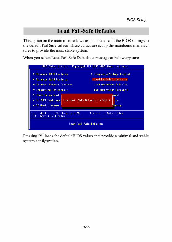
This option on the main menu allows users to restore all the BIOS settings tothe default Fail Safe values. These values are set by the mainboard manufac-turer to provide the most stable system.
When you select Load-Fail Safe Defaults, a message as below appears:
Pressing ‘Y’ loads the default BIOS values that provide a minimal and stablesystem configuration.
Load Fail-Safe Defaults
Chapter 3
3-26
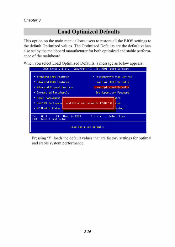
This option on the main menu allows users to restore all the BIOS settings tothe default Optimized values. The Optimized Defaults are the default valuesalso set by the mainboard manufacturer for both optimized and stable perform-ance of the mainboard.
When you select Load Optimized Defaults, a message as below appears:
Pressing ‘Y’ loads the default values that are factory settings for optimaland stable system performance.
Load Optimized Defaults

BIOS Setup
3-27
When you select this function, a message as below will appear on the screen:
Type the password, up to eight characters in length, and press <Enter>.The password typed now will clear any previously set password fromCMOS memory. You will be prompted to confirm the password. Re-typethe password and press <Enter>. You may also press <Esc> to abort theselection and not enter a password.
To clear a set password, just press <Enter> when you are prompted toenter the password. A message will show up confirming that the pass-word will be disabled. Once the password is disabled, the system willboot and you can enter Setup without entering any password.
When a password has been set, you will be prompted to enter it everytime you try to enter Setup. This prevents an unauthorized person fromchanging any part of your system configuration.
Additionally, when a password is enabled, you can also have BIOS torequest a password each time the system is booted. This would preventunauthorized use of your computer. The setting to determine when thepassword prompt is required is the Security Option of the AdvancedBIOS Features menu. If the Security Option is set to System, the passwordis required both at boot and at entry to Setup. If set to Setup, passwordprompt only occurs when trying to enter Setup.
Set Supervisor/User Password
Chapter 3
3-28
About Supervisor Password & User Password:Supervisor password : Can enter and change the settings of
the setup menus.User password: Can only enter but do not have the right
to change the settings of the setupmenus.

BIOS Setup
3-29
When you want to quit the Setup menu, you can select this option to save thechanges and quit. A message as below will appear on the screen:
Typing “Y” will allow you to quit the Setup Utility and save the user setupchanges to RTC CMOS.
Typing “N” will return to the Setup Utility.
Save & Exit Setup

Chapter 3
3-30
Exit Without SavingWhen you want to quit the Setup menu, you can select this option to abandonthe changes. A message as below will appear on the screen:
Typing “Y” will allow you to quit the Setup Utility without saving anychanges to RTC CMOS.
Typing “N” will return to the Setup Utility.
Driver Setup
4-1
This chapter gives you brief descriptions of eachmainboard drivers and applications. It consists of thefollowing topic:
Note: You must install VIA chipset drivers first beforeinstalling other drivers such as audio or VGA drivers.The applications will only function correctly if the nec-essary drivers are already installed.
Driver Utilities CD Content 4-2
Software Setup
44444
Chapter 4
4-2
Driver Utilities CD Content
Getting StartedThe VIA EPIA-V mainboard includes a Driver Utilities CD which containsdriver utilities and software to enhance the performance of the mainboard.Please check that you have this CD in your gift box. If the CD is missing inyour gift box, please contact your local dealer for the CD.
Note: The driver utilities and software are updated from time to time. Pleasevisit VIA’s website (http://www.viamainboard.com/) for the latest updateddriver utilities and software.
Running the Driver Utilities CDTo start using the CD, just simply insert the CD into your local CD-ROM orDVD-ROM drive. The CD should run automatically when you close your CD-ROM or DVD-ROM drive. The driver utilities and software menu screenshould then appear on your desktop. If the CD does not run automatically,you can run the CD manually by typing “D:\Setup.exe” at Start\Run.
(Please note that D: might not be your CD-ROM/DVD-ROM drive’s letter.Make sure you type the correct letter of CD-ROM/DVD-ROM drive on yoursystem).
CD ContentUpon running the CD, the following driver utilities and software menu screenappears as follow:

Driver Setup
4-3
The driver utilities and software in this CD are:
- VIA 4in1 Drivers: Contains VIA ATAPI Vendor Support Driver (enables theperformance enhancing bus mastering functions on ATA-capable Hard DiskDrives and ensures IDE device compatibility), AGP VxD Driver (providesservice routines to your VGA driver and interface directly to hardware,providing fast graphical access), IRQ Routing Miniport Driver (sets thesystem’s PCI IRQ routing sequence) and VIA INF Driver (enables the VIAPower Management function).
- VIA Graphics Driver: Enhance the onboard VIA graphic chip.
- VIA Audio Driver: Enhance the onboard VIA audio chip.
- VIA LAN Driver: Enhance the onboard VIA LAN chip.
- VIA FIR Driver: Support for FIR.