Embed Size (px)
Citation preview

L
EDS84AVBDxx13292140
Ä.>6Iä
Software Manual
E84AVBDExxxxxx0
8400 BaseLine D Inverter Drives
8400
L-force Drivesefesotomasyon.com - Lenze

8400 BaseLine D | Software ManualOverview of the technical documentation for Inverter Drives 8400
2 L Firmware 03.00 - DMS EN 5.1 - 11/2009
Overview of the technical documentation for Inverter Drives 8400
Project planning, selecting & ordering Legend:
8400 Hardware Manual Printed documentation
Catalogue Online documentation(PDF/»Engineer« online help)
Mounting & wiring Abbreviations used
MA 8400 BaseLine/8400StateLine/HighLine BA Operating Instructions
MA for communication module KHB Communication Manual
MA for extension module MA Mounting Instructions
MA for safety module SW Software Manual
MA for accessories
Parameter setting
BA keypad
SW 8400 BaseLine C
SW 8400 BaseLine D This documentation
SW 8400 StateLine
SW 8400 HighLine
KHB for communication module
Commissioning of the drive
Commissioning guide
SW 8400 StateLine/HighLine
Chapter "Commissioning"
Chapter "Oscilloscope"
Chapter "Diagnostics & fault analysis"
Networking
KHB for communication medium used
efesotomasyon.com - Lenze

Firmware 03.00 - DMS EN 5.1 - 11/2009 L 3
8400 BaseLine D | Software ManualContents
Contents
1 About this documentation . . . . . . . . . . . . . . . . . . . . . . . . . . . . . . . . . . . . . . . . . . . . . . . . . . . . . . . . . 9
1.1 Document history . . . . . . . . . . . . . . . . . . . . . . . . . . . . . . . . . . . . . . . . . . . . . . . . . . . . . . . . . . . . . . . 9
1.2 Conventions used . . . . . . . . . . . . . . . . . . . . . . . . . . . . . . . . . . . . . . . . . . . . . . . . . . . . . . . . . . . . . . . 10
1.3 Terminology used . . . . . . . . . . . . . . . . . . . . . . . . . . . . . . . . . . . . . . . . . . . . . . . . . . . . . . . . . . . . . . . 10
1.4 Definition of notes used . . . . . . . . . . . . . . . . . . . . . . . . . . . . . . . . . . . . . . . . . . . . . . . . . . . . . . . . . 12
2 Product description . . . . . . . . . . . . . . . . . . . . . . . . . . . . . . . . . . . . . . . . . . . . . . . . . . . . . . . . . . . . . . . 13
2.1 Functions of the frequency inverter . . . . . . . . . . . . . . . . . . . . . . . . . . . . . . . . . . . . . . . . . . . . . . 13
2.2 Memory module . . . . . . . . . . . . . . . . . . . . . . . . . . . . . . . . . . . . . . . . . . . . . . . . . . . . . . . . . . . . . . . . 14
2.3 Communicating with the controller . . . . . . . . . . . . . . . . . . . . . . . . . . . . . . . . . . . . . . . . . . . . . . 15
2.3.1 Going online via diagnostic adapter . . . . . . . . . . . . . . . . . . . . . . . . . . . . . . . . . . . . . . 15
2.4 Internal Keypad . . . . . . . . . . . . . . . . . . . . . . . . . . . . . . . . . . . . . . . . . . . . . . . . . . . . . . . . . . . . . . . . . 19
3 Commissioning . . . . . . . . . . . . . . . . . . . . . . . . . . . . . . . . . . . . . . . . . . . . . . . . . . . . . . . . . . . . . . . . . . . 21
3.1 Before switching on . . . . . . . . . . . . . . . . . . . . . . . . . . . . . . . . . . . . . . . . . . . . . . . . . . . . . . . . . . . . . 21
3.2 Parameter setting and diagnosing directly at the controller. . . . . . . . . . . . . . . . . . . . . . . . 23
3.2.1 Menu structure . . . . . . . . . . . . . . . . . . . . . . . . . . . . . . . . . . . . . . . . . . . . . . . . . . . . . . . . . . 24
3.2.2 Diagnostics. . . . . . . . . . . . . . . . . . . . . . . . . . . . . . . . . . . . . . . . . . . . . . . . . . . . . . . . . . . . . . 25
3.2.3 Messages . . . . . . . . . . . . . . . . . . . . . . . . . . . . . . . . . . . . . . . . . . . . . . . . . . . . . . . . . . . . . . . 26
3.3 Test commissioning . . . . . . . . . . . . . . . . . . . . . . . . . . . . . . . . . . . . . . . . . . . . . . . . . . . . . . . . . . . . . 27
3.3.1 Test commissioning with keypad control. . . . . . . . . . . . . . . . . . . . . . . . . . . . . . . . . . 29
3.3.2 Test commissioning with terminal control . . . . . . . . . . . . . . . . . . . . . . . . . . . . . . . . 31
3.4 Commissioning of the drive application with the »Engineer« . . . . . . . . . . . . . . . . . . . . . . 33
3.4.1 Observe the safety measures . . . . . . . . . . . . . . . . . . . . . . . . . . . . . . . . . . . . . . . . . . . . . 34
3.4.2 Open the »Engineer« . . . . . . . . . . . . . . . . . . . . . . . . . . . . . . . . . . . . . . . . . . . . . . . . . . . . 35
3.4.3 Load the Lenze setting . . . . . . . . . . . . . . . . . . . . . . . . . . . . . . . . . . . . . . . . . . . . . . . . . . . 36
3.4.4 Make motor settings. . . . . . . . . . . . . . . . . . . . . . . . . . . . . . . . . . . . . . . . . . . . . . . . . . . . . 36
3.4.5 Select control source . . . . . . . . . . . . . . . . . . . . . . . . . . . . . . . . . . . . . . . . . . . . . . . . . . . . . 37
3.4.6 Start program . . . . . . . . . . . . . . . . . . . . . . . . . . . . . . . . . . . . . . . . . . . . . . . . . . . . . . . . . . . 39
3.4.7 Diagnostics. . . . . . . . . . . . . . . . . . . . . . . . . . . . . . . . . . . . . . . . . . . . . . . . . . . . . . . . . . . . . . 40
3.5 Password protection . . . . . . . . . . . . . . . . . . . . . . . . . . . . . . . . . . . . . . . . . . . . . . . . . . . . . . . . . . . . 41
3.5.1 Entry of a password not available yet . . . . . . . . . . . . . . . . . . . . . . . . . . . . . . . . . . . . . 42
3.5.2 Delete or change available password . . . . . . . . . . . . . . . . . . . . . . . . . . . . . . . . . . . . . 43
3.5.3 Access password-protected controller without knowing the password. . . . . . 44
3.5.4 Reach password-protected menu level with knowing the password . . . . . . . . 45
efesotomasyon.com - Lenze

8400 BaseLine D | Software ManualContents
4 L Firmware 03.00 - DMS EN 5.1 - 11/2009
4 Drive control (DCTRL) . . . . . . . . . . . . . . . . . . . . . . . . . . . . . . . . . . . . . . . . . . . . . . . . . . . . . . . . . . . . . . 47
4.1 Device states. . . . . . . . . . . . . . . . . . . . . . . . . . . . . . . . . . . . . . . . . . . . . . . . . . . . . . . . . . . . . . . . . . . . 48
4.1.1 "Init" state . . . . . . . . . . . . . . . . . . . . . . . . . . . . . . . . . . . . . . . . . . . . . . . . . . . . . . . . . . . . . . 49
4.1.2 "MotorIdent" status. . . . . . . . . . . . . . . . . . . . . . . . . . . . . . . . . . . . . . . . . . . . . . . . . . . . . . 50
4.1.3 "SafeTorqueOff" state. . . . . . . . . . . . . . . . . . . . . . . . . . . . . . . . . . . . . . . . . . . . . . . . . . . . 50
4.1.4 "ReadyToSwitchON" state . . . . . . . . . . . . . . . . . . . . . . . . . . . . . . . . . . . . . . . . . . . . . . . . 51
4.1.5 "SwitchedON" state. . . . . . . . . . . . . . . . . . . . . . . . . . . . . . . . . . . . . . . . . . . . . . . . . . . . . . 53
4.1.6 "OperationEnabled" state . . . . . . . . . . . . . . . . . . . . . . . . . . . . . . . . . . . . . . . . . . . . . . . . 53
4.1.7 Status display "Warning". . . . . . . . . . . . . . . . . . . . . . . . . . . . . . . . . . . . . . . . . . . . . . . . . 53
4.1.8 "Trouble" state . . . . . . . . . . . . . . . . . . . . . . . . . . . . . . . . . . . . . . . . . . . . . . . . . . . . . . . . . . 54
4.1.9 "Fault" state . . . . . . . . . . . . . . . . . . . . . . . . . . . . . . . . . . . . . . . . . . . . . . . . . . . . . . . . . . . . . 55
4.2 Controller commands . . . . . . . . . . . . . . . . . . . . . . . . . . . . . . . . . . . . . . . . . . . . . . . . . . . . . . . . . . . 56
4.2.1 General information . . . . . . . . . . . . . . . . . . . . . . . . . . . . . . . . . . . . . . . . . . . . . . . . . . . . . 56
4.2.2 Overview of device commands . . . . . . . . . . . . . . . . . . . . . . . . . . . . . . . . . . . . . . . . . . . 59
4.2.3 Status display for device command . . . . . . . . . . . . . . . . . . . . . . . . . . . . . . . . . . . . . . . 59
4.2.4 Load Lenze setting . . . . . . . . . . . . . . . . . . . . . . . . . . . . . . . . . . . . . . . . . . . . . . . . . . . . . . . 60
4.2.5 Save parameter set . . . . . . . . . . . . . . . . . . . . . . . . . . . . . . . . . . . . . . . . . . . . . . . . . . . . . . 60
4.2.6 Load parameter set . . . . . . . . . . . . . . . . . . . . . . . . . . . . . . . . . . . . . . . . . . . . . . . . . . . . . . 61
4.3 System block "LS_DriveInterface" . . . . . . . . . . . . . . . . . . . . . . . . . . . . . . . . . . . . . . . . . . . . . . . . 63
4.4 Parameter setting . . . . . . . . . . . . . . . . . . . . . . . . . . . . . . . . . . . . . . . . . . . . . . . . . . . . . . . . . . . . . . . 66
4.4.1 General information . . . . . . . . . . . . . . . . . . . . . . . . . . . . . . . . . . . . . . . . . . . . . . . . . . . . . 66
4.4.2 Saving of the parameters in the memory module. . . . . . . . . . . . . . . . . . . . . . . . . . 67
4.4.3 Handling of the memory module . . . . . . . . . . . . . . . . . . . . . . . . . . . . . . . . . . . . . . . . . 68
4.4.4 Non-volatile saving of parameters . . . . . . . . . . . . . . . . . . . . . . . . . . . . . . . . . . . . . . . . 69
4.4.5 Parameter set transfer . . . . . . . . . . . . . . . . . . . . . . . . . . . . . . . . . . . . . . . . . . . . . . . . . . . 69
4.4.6 Parameters for status display. . . . . . . . . . . . . . . . . . . . . . . . . . . . . . . . . . . . . . . . . . . . . 70
4.4.7 Set/remove controller inhibit. . . . . . . . . . . . . . . . . . . . . . . . . . . . . . . . . . . . . . . . . . . . . 70
4.5 Activate/deactivate quick stop function (QSP) . . . . . . . . . . . . . . . . . . . . . . . . . . . . . . . . . . . . 71
efesotomasyon.com - Lenze

Firmware 03.00 - DMS EN 5.1 - 11/2009 L 5
8400 BaseLine D | Software ManualContents
5 Motor control (MCTRL). . . . . . . . . . . . . . . . . . . . . . . . . . . . . . . . . . . . . . . . . . . . . . . . . . . . . . . . . . . . . 73
5.1 Selection of the operating mode . . . . . . . . . . . . . . . . . . . . . . . . . . . . . . . . . . . . . . . . . . . . . . . . . 74
5.1.1 V/f characteristic control . . . . . . . . . . . . . . . . . . . . . . . . . . . . . . . . . . . . . . . . . . . . . . . . . 77
5.1.1.1 Parameter setting of the V/f characteristic control. . . . . . . . . . . . . . . 79
5.1.1.2 Optimisation of operational performance by slip compensation . . 83
5.1.1.3 Optimisation of the Imax controller setting . . . . . . . . . . . . . . . . . . . . . . 85
5.1.2 Vector control . . . . . . . . . . . . . . . . . . . . . . . . . . . . . . . . . . . . . . . . . . . . . . . . . . . . . . . . . . . 86
5.1.2.1 Sensorless vector control (SLVC) . . . . . . . . . . . . . . . . . . . . . . . . . . . . . . . . 87
5.1.3 Automatic motor parameter identification. . . . . . . . . . . . . . . . . . . . . . . . . . . . . . . . 93
5.2 Motor selection . . . . . . . . . . . . . . . . . . . . . . . . . . . . . . . . . . . . . . . . . . . . . . . . . . . . . . . . . . . . . . . . . 95
5.2.1 Manual parameter setting of external motors. . . . . . . . . . . . . . . . . . . . . . . . . . . . . 96
5.3 Selection of the switching frequency . . . . . . . . . . . . . . . . . . . . . . . . . . . . . . . . . . . . . . . . . . . . . 97
5.4 Definition of current and speed limits . . . . . . . . . . . . . . . . . . . . . . . . . . . . . . . . . . . . . . . . . . . . 99
5.4.1 Definition of speed limits . . . . . . . . . . . . . . . . . . . . . . . . . . . . . . . . . . . . . . . . . . . . . . . . 99
5.4.2 Definition of current limits . . . . . . . . . . . . . . . . . . . . . . . . . . . . . . . . . . . . . . . . . . . . . . . 100
5.5 Flying restart function . . . . . . . . . . . . . . . . . . . . . . . . . . . . . . . . . . . . . . . . . . . . . . . . . . . . . . . . . . . 101
5.5.1 General information . . . . . . . . . . . . . . . . . . . . . . . . . . . . . . . . . . . . . . . . . . . . . . . . . . . . . 101
5.6 DC-injection braking . . . . . . . . . . . . . . . . . . . . . . . . . . . . . . . . . . . . . . . . . . . . . . . . . . . . . . . . . . . . 103
5.6.1 Manual DC-injection braking (DCB) . . . . . . . . . . . . . . . . . . . . . . . . . . . . . . . . . . . . . . . 104
5.6.2 Automatic DC-injection braking (Auto-DCB). . . . . . . . . . . . . . . . . . . . . . . . . . . . . . . 105
5.6.3 Oscillation damping . . . . . . . . . . . . . . . . . . . . . . . . . . . . . . . . . . . . . . . . . . . . . . . . . . . . . 107
5.7 Signal flow. . . . . . . . . . . . . . . . . . . . . . . . . . . . . . . . . . . . . . . . . . . . . . . . . . . . . . . . . . . . . . . . . . . . . . 108
5.8 System block "LS_MotorInterface" . . . . . . . . . . . . . . . . . . . . . . . . . . . . . . . . . . . . . . . . . . . . . . . 110
5.9 Monitoring functions. . . . . . . . . . . . . . . . . . . . . . . . . . . . . . . . . . . . . . . . . . . . . . . . . . . . . . . . . . . . 111
5.9.1 Motor temperature monitoring with I²xt. . . . . . . . . . . . . . . . . . . . . . . . . . . . . . . . . . 111
6 I/O terminals . . . . . . . . . . . . . . . . . . . . . . . . . . . . . . . . . . . . . . . . . . . . . . . . . . . . . . . . . . . . . . . . . . . . . 115
6.1 Analog input . . . . . . . . . . . . . . . . . . . . . . . . . . . . . . . . . . . . . . . . . . . . . . . . . . . . . . . . . . . . . . . . . . . . 116
6.1.1 Terminal assignment/electrical data. . . . . . . . . . . . . . . . . . . . . . . . . . . . . . . . . . . . . . 117
6.1.2 Parameter setting . . . . . . . . . . . . . . . . . . . . . . . . . . . . . . . . . . . . . . . . . . . . . . . . . . . . . . . 118
6.1.3 Using the analog input as current input. . . . . . . . . . . . . . . . . . . . . . . . . . . . . . . . . . . 118
6.1.4 System block "LS_AnalogInput". . . . . . . . . . . . . . . . . . . . . . . . . . . . . . . . . . . . . . . . . . . 119
6.2 Digital inputs . . . . . . . . . . . . . . . . . . . . . . . . . . . . . . . . . . . . . . . . . . . . . . . . . . . . . . . . . . . . . . . . . . . 120
6.2.1 Terminal assignment/electrical data. . . . . . . . . . . . . . . . . . . . . . . . . . . . . . . . . . . . . . 120
6.2.2 Parameter setting . . . . . . . . . . . . . . . . . . . . . . . . . . . . . . . . . . . . . . . . . . . . . . . . . . . . . . . 120
6.2.3 System block "LS_DigitalInput" . . . . . . . . . . . . . . . . . . . . . . . . . . . . . . . . . . . . . . . . . . . 121
6.3 Digital outputs . . . . . . . . . . . . . . . . . . . . . . . . . . . . . . . . . . . . . . . . . . . . . . . . . . . . . . . . . . . . . . . . . . 122
6.3.1 Terminal assignment/electrical data. . . . . . . . . . . . . . . . . . . . . . . . . . . . . . . . . . . . . . 122
6.3.2 Parameter setting . . . . . . . . . . . . . . . . . . . . . . . . . . . . . . . . . . . . . . . . . . . . . . . . . . . . . . . 123
6.3.3 Function block "LS_DigitalOutput". . . . . . . . . . . . . . . . . . . . . . . . . . . . . . . . . . . . . . . . 123
efesotomasyon.com - Lenze
8400 BaseLine D | Software ManualContents
6 L Firmware 03.00 - DMS EN 5.1 - 11/2009
7 Error management . . . . . . . . . . . . . . . . . . . . . . . . . . . . . . . . . . . . . . . . . . . . . . . . . . . . . . . . . . . . . . . . 125
7.1 Basics on error handling in the controller . . . . . . . . . . . . . . . . . . . . . . . . . . . . . . . . . . . . . . . . . 125
7.2 Drive diagnostics with the »Engineer«. . . . . . . . . . . . . . . . . . . . . . . . . . . . . . . . . . . . . . . . . . . . 125
7.3 Logbook . . . . . . . . . . . . . . . . . . . . . . . . . . . . . . . . . . . . . . . . . . . . . . . . . . . . . . . . . . . . . . . . . . . . . . . . 129
7.3.1 Functional description . . . . . . . . . . . . . . . . . . . . . . . . . . . . . . . . . . . . . . . . . . . . . . . . . . . 130
7.3.2 Reading out logbook entries. . . . . . . . . . . . . . . . . . . . . . . . . . . . . . . . . . . . . . . . . . . . . . 131
7.4 Monitoring . . . . . . . . . . . . . . . . . . . . . . . . . . . . . . . . . . . . . . . . . . . . . . . . . . . . . . . . . . . . . . . . . . . . . 132
7.4.1 Setting the error response. . . . . . . . . . . . . . . . . . . . . . . . . . . . . . . . . . . . . . . . . . . . . . . . 133
7.4.2 Monitoring of the device utilisation. . . . . . . . . . . . . . . . . . . . . . . . . . . . . . . . . . . . . . . 133
7.5 Error messages of the operating system . . . . . . . . . . . . . . . . . . . . . . . . . . . . . . . . . . . . . . . . . . 134
7.5.1 Error number . . . . . . . . . . . . . . . . . . . . . . . . . . . . . . . . . . . . . . . . . . . . . . . . . . . . . . . . . . . . 134
7.5.1.1 Structure of the error number (bit coding). . . . . . . . . . . . . . . . . . . . . . . 134
7.5.1.2 Error type . . . . . . . . . . . . . . . . . . . . . . . . . . . . . . . . . . . . . . . . . . . . . . . . . . . . . 134
7.5.1.3 Error subject area . . . . . . . . . . . . . . . . . . . . . . . . . . . . . . . . . . . . . . . . . . . . . . 134
7.5.1.4 Error ID. . . . . . . . . . . . . . . . . . . . . . . . . . . . . . . . . . . . . . . . . . . . . . . . . . . . . . . . 135
7.5.1.5 Example for bit coding of the error number . . . . . . . . . . . . . . . . . . . . . 135
7.5.2 Reset of error message . . . . . . . . . . . . . . . . . . . . . . . . . . . . . . . . . . . . . . . . . . . . . . . . . . . 136
7.5.3 Short overview (A-Z) . . . . . . . . . . . . . . . . . . . . . . . . . . . . . . . . . . . . . . . . . . . . . . . . . . . . . 137
7.5.4 Cause & possible remedies . . . . . . . . . . . . . . . . . . . . . . . . . . . . . . . . . . . . . . . . . . . . . . . 138
8 Drive Application . . . . . . . . . . . . . . . . . . . . . . . . . . . . . . . . . . . . . . . . . . . . . . . . . . . . . . . . . . . . . . . . . 141
8.1 Overview of the software structure of the drive application function. . . . . . . . . . . . . . . 142
8.1.1 Input and output interconnection of the drive application . . . . . . . . . . . . . . . . . 143
8.1.2 Functions of the drive application "Actuating drive - speed" . . . . . . . . . . . . . . . . 144
8.1.3 Pre-assignment of the drive application. . . . . . . . . . . . . . . . . . . . . . . . . . . . . . . . . . . 146
8.2 Interface description of the drive application . . . . . . . . . . . . . . . . . . . . . . . . . . . . . . . . . . . . . 148
efesotomasyon.com - Lenze

Firmware 03.00 - DMS EN 5.1 - 11/2009 L 7
8400 BaseLine D | Software ManualContents
9 Function library . . . . . . . . . . . . . . . . . . . . . . . . . . . . . . . . . . . . . . . . . . . . . . . . . . . . . . . . . . . . . . . . . . . 153
9.1 Function blocks . . . . . . . . . . . . . . . . . . . . . . . . . . . . . . . . . . . . . . . . . . . . . . . . . . . . . . . . . . . . . . . . . 153
9.1.1 L_NSet . . . . . . . . . . . . . . . . . . . . . . . . . . . . . . . . . . . . . . . . . . . . . . . . . . . . . . . . . . . . . . . . . . 153
9.1.1.1 Main setpoint path . . . . . . . . . . . . . . . . . . . . . . . . . . . . . . . . . . . . . . . . . . . . 154
9.1.1.2 JOG setpoints. . . . . . . . . . . . . . . . . . . . . . . . . . . . . . . . . . . . . . . . . . . . . . . . . . 155
9.1.1.3 Setpoint inversion . . . . . . . . . . . . . . . . . . . . . . . . . . . . . . . . . . . . . . . . . . . . . 155
9.1.1.4 Ramp function generator for the main setpoint . . . . . . . . . . . . . . . . . 156
9.1.1.5 S-shaped ramp . . . . . . . . . . . . . . . . . . . . . . . . . . . . . . . . . . . . . . . . . . . . . . . . 156
9.1.2 L_MPot . . . . . . . . . . . . . . . . . . . . . . . . . . . . . . . . . . . . . . . . . . . . . . . . . . . . . . . . . . . . . . . . . 157
9.1.2.1 Activation & control of motor potentiometer. . . . . . . . . . . . . . . . . . . . 159
9.1.2.2 Deactivation of motor potentiometer . . . . . . . . . . . . . . . . . . . . . . . . . . . 160
9.1.2.3 Save current output value after mains failure . . . . . . . . . . . . . . . . . . . 160
9.1.3 L_PCTRL . . . . . . . . . . . . . . . . . . . . . . . . . . . . . . . . . . . . . . . . . . . . . . . . . . . . . . . . . . . . . . . . . 161
9.1.3.1 Control characteristic . . . . . . . . . . . . . . . . . . . . . . . . . . . . . . . . . . . . . . . . . . 164
9.1.3.2 Ramp function generator. . . . . . . . . . . . . . . . . . . . . . . . . . . . . . . . . . . . . . . 165
9.1.3.3 Value range of the output signal. . . . . . . . . . . . . . . . . . . . . . . . . . . . . . . . 165
9.1.3.4 Evaluation of the output signal . . . . . . . . . . . . . . . . . . . . . . . . . . . . . . . . . 165
9.1.3.5 Deactivation of the process controller. . . . . . . . . . . . . . . . . . . . . . . . . . . 166
9.1.4 L_RLQ . . . . . . . . . . . . . . . . . . . . . . . . . . . . . . . . . . . . . . . . . . . . . . . . . . . . . . . . . . . . . . . . . . . 167
9.1.5 LS_DisFree . . . . . . . . . . . . . . . . . . . . . . . . . . . . . . . . . . . . . . . . . . . . . . . . . . . . . . . . . . . . . . 168
9.1.6 LS_DisFree_a . . . . . . . . . . . . . . . . . . . . . . . . . . . . . . . . . . . . . . . . . . . . . . . . . . . . . . . . . . . . 169
9.1.7 LS_DisFree_b . . . . . . . . . . . . . . . . . . . . . . . . . . . . . . . . . . . . . . . . . . . . . . . . . . . . . . . . . . . . 170
9.1.8 LS_ParFix. . . . . . . . . . . . . . . . . . . . . . . . . . . . . . . . . . . . . . . . . . . . . . . . . . . . . . . . . . . . . . . . 171
9.1.9 LS_ParFree_b . . . . . . . . . . . . . . . . . . . . . . . . . . . . . . . . . . . . . . . . . . . . . . . . . . . . . . . . . . . . 172
9.1.10 LS_ParFree_a . . . . . . . . . . . . . . . . . . . . . . . . . . . . . . . . . . . . . . . . . . . . . . . . . . . . . . . . . . . . 173
10 Parameter reference. . . . . . . . . . . . . . . . . . . . . . . . . . . . . . . . . . . . . . . . . . . . . . . . . . . . . . . . . . . . . . . 175
10.1 Structure of the parameter descriptions . . . . . . . . . . . . . . . . . . . . . . . . . . . . . . . . . . . . . . . . . . 176
10.1.1 Data type . . . . . . . . . . . . . . . . . . . . . . . . . . . . . . . . . . . . . . . . . . . . . . . . . . . . . . . . . . . . . . . 177
10.1.2 Parameters with read-only access . . . . . . . . . . . . . . . . . . . . . . . . . . . . . . . . . . . . . . . . 177
10.1.3 Parameters with write access . . . . . . . . . . . . . . . . . . . . . . . . . . . . . . . . . . . . . . . . . . . . 178
10.1.3.1 Parameters with setting range . . . . . . . . . . . . . . . . . . . . . . . . . . . . . . . . . 178
10.1.3.2 Parameters with selection list . . . . . . . . . . . . . . . . . . . . . . . . . . . . . . . . . . 178
10.1.3.3 Parameters with bit-coded setting . . . . . . . . . . . . . . . . . . . . . . . . . . . . . . 179
10.1.3.4 Parameters with subcodes . . . . . . . . . . . . . . . . . . . . . . . . . . . . . . . . . . . . . 180
10.1.4 Parameter attributes . . . . . . . . . . . . . . . . . . . . . . . . . . . . . . . . . . . . . . . . . . . . . . . . . . . . 180
10.2 Parameter list . . . . . . . . . . . . . . . . . . . . . . . . . . . . . . . . . . . . . . . . . . . . . . . . . . . . . . . . . . . . . . . . . . . 182
10.3 Table of attributes . . . . . . . . . . . . . . . . . . . . . . . . . . . . . . . . . . . . . . . . . . . . . . . . . . . . . . . . . . . . . . 227
11 Index . . . . . . . . . . . . . . . . . . . . . . . . . . . . . . . . . . . . . . . . . . . . . . . . . . . . . . . . . . . . . . . . . . . . . . . . . . . . 231
Your opinion is important to us. . . . . . . . . . . . . . . . . . . . . . . . . . . . . . . . . . . . . . . . . . . . . . . . . . . . . . . . . 235
efesotomasyon.com - Lenze

8400 BaseLine D | Software ManualContents
8 L Firmware 03.00 - DMS EN 5.1 - 11/2009
efesotomasyon.com - Lenze

Firmware 03.00 - DMS EN 5.1 - 11/2009 L 9
8400 BaseLine D | Software ManualAbout this documentation
Document history
1 About this documentation
This Software Manual contains information about the parameterisation of the8400 BaseLine D controller using the L-force »Engineer« and the keypad.
The information given in this Software Manual applies to the 8400 BaseLine D frequencyinverter with the following nameplate data:
Tip!
Current documentation and software updates for Lenze products can be found onthe Internet in the "Services & Downloads" area under
http://www.Lenze.com
1.1 Document history
Danger!
The controller is a source of danger which may lead to death or severe injury of persons.
To protect yourself and others against these dangers, observe the safety instructions before switching on the controller.
Please read the safety instructions provided in the 8400 Mounting Instructions and in the 8400 Hardware Manual. Both documents are supplied with the controller.
Type Type designation From software version
Important
8400 BaseLine D E84AVBDExxxxSX0 2.1 Variant without digital output X4/DO1
8400 BaseLine D E84AVBDExxxxSX1 2.1 Variant with digital output X4/DO1Digital outputs ( 122)
8400 BaseLine D E84AVBDExxxxxx0 3.0 New function block L_PCTRL
Version Description
1.0 06/2008 TD06 First edition
2.0 07/2008 TD 06 Second edition
3.0 02/2009 TD 06 New: The chapters "Commissioning" and "Parameter reference" have been revised, new block L_RLQ (CW/CCW rotation)
4.0 04/2009 TD 06 New: Subcode c012 in C002 for adaption of parameter sets from controllers with firmware version ≤ V2.1 in the event of service.
5.0 04/2009 TD 06 New: • Function block L_PCTRL • Quick saving at the push of a button ( 61) • Parameter list with info texts
5.1 11/2009 TD06 Changes compared to previous issue affects the parameter C018 and the drawings [8-2] , [8-3]
efesotomasyon.com - Lenze

8400 BaseLine D | Software ManualAbout this documentationConventions used
10 L Firmware 03.00 - DMS EN 5.1 - 11/2009
1.2 Conventions used
This Software Manual uses the following conventions to distinguish between differenttypes of information:
1.3 Terminology used
Type of information Writing Examples/notes
Variable identifier Italics By setting bEnable to TRUE...
Window The Message window... / The Options dialog box...
Control element Bold The OK button... / The Copy command... / The Properties tab... / The Name input field...
Sequence ofmenu commands
If several commands must be used in sequence to carry out a function, then the individual commands are separated by an arrow: Select FileOpen to...
Shortcut <Bold> Press <F1> to open the Online Help.
If a command requires a combination of keys, a "+" is placed between the key symbols: Use <Shift>+<ESC> to...
Hyperlink Underlined A hyperlink is an optically highlighted reference which is activated by a mouse click.
Step-by-step instructions Step-by-step instructions are indicated by a pictograph.
Term Meaning
»Engineer« Lenze PC software which supports you in "engineering" (parameterisation, diagnostics and configuration) throughout the whole life cycle, i.e. from planning to maintenance of the commissioned machine.
Application block Block for a drive application (e.g. actuating drive - speed)A drive application is a drive solution provided with the experiences and know-how of Lenze in which function blocks interconnected to a signal flow form the basis for implementing typical drive tasks.
Code Parameter used for controller parameter setting or monitoring. The term is usually called "index".
Display codes Parameter that displays the current status or value of a system block input/output.
FB Editor Function block editorGraphical interconnection tool which is provided for signal interconnections in the »Engineer« on the FB editor tab and by means of which the applications integrated in the drive can also be reconfigured and extended by individual functions.
Function block A function block can be compared with an integrated circuit that contains a certain control logic and delivers one or several values when being executed. • Each function block has a unique identifier (the instance name) and a
processing number which defines the position at which the function block is calculated during the task cycle.
Lenze setting This setting is the default factory setting of the device.
Port block Block for implementing the process data transfer via a fieldbus
QSP Quick stop
SC Operating mode: Servo Control
SLVC Operating mode: SensorLess Vector Control
efesotomasyon.com - Lenze
Firmware 03.00 - DMS EN 5.1 - 11/2009 L 11
8400 BaseLine D | Software ManualAbout this documentation
Terminology used
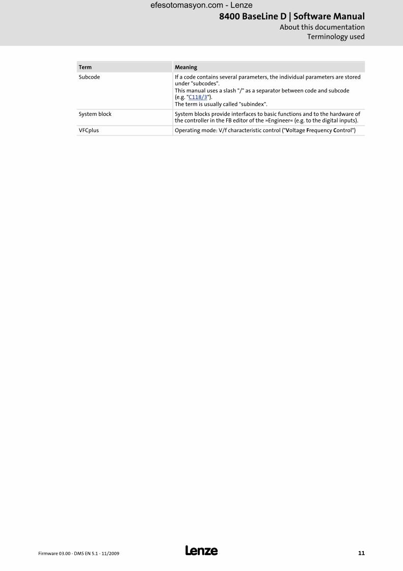
Subcode If a code contains several parameters, the individual parameters are stored under "subcodes".This manual uses a slash "/" as a separator between code and subcode (e.g. "C118/3").The term is usually called "subindex".
System block System blocks provide interfaces to basic functions and to the hardware of the controller in the FB editor of the »Engineer« (e.g. to the digital inputs).
VFCplus Operating mode: V/f characteristic control ("Voltage Frequency Control")
Term Meaning
efesotomasyon.com - Lenze

8400 BaseLine D | Software ManualAbout this documentationDefinition of notes used
12 L Firmware 03.00 - DMS EN 5.1 - 11/2009
1.4 Definition of notes used
The following signal words and symbols are used in this Software Manual to indicatedangers and important information:
Safety instructions
Layout of the safety instructions:
Application notes
Pictograph and signal word!
(characterise the type and severity of danger)
Note
(describes the danger and informs how to prevent dangerous situations)
Pictograph Signal word Meaning
Danger! Danger of personal injury through dangerous electrical voltageReference to an imminent danger that may result in death or serious personal injury if the corresponding measures are not taken.
Danger! Danger of personal injury through a general source of dangerReference to an imminent danger that may result in death or serious personal injury if the corresponding measures are not taken.
Stop! Danger of property damageReference to a possible danger that may result in property damage if the corresponding measures are not taken.
Pictograph Signal word Meaning
Note! Important note to ensure trouble-free operation
Tip! Useful tip for easy handling
efesotomasyon.com - Lenze

Firmware 03.00 - DMS EN 5.1 - 11/2009 L 13
8400 BaseLine D | Software ManualProduct description
Functions of the frequency inverter
2 Product description
2.1 Functions of the frequency inverter
Memory module for parameter transfer and quick and easy device replacement
Approved for use in balanced supply systems (TN systems)
Wide input voltage range up to 500V (+10%) for a worldwide application without using additional transformers
Approvals CE, UL
High overload capacity up to 200% for generating high breakaway torques and for a fault-tolerant operation
Integrated brake transistor (brake chopper) only available with devices operating at 400 V / 500 V.
Integrated interface for diagnostics via PC with extensive diagnostic options
Integrated protective functions
Adjustable warning levels for a simplified and safe machine maintenance (e.g. motor operating time)
Adjustable password to protect your parameter setting
Saving of all parameters at the push of a button
Relay output
DC connection
Integrated EMC shield connections for control cables
efesotomasyon.com - Lenze

8400 BaseLine D | Software ManualProduct descriptionMemory module
14 L Firmware 03.00 - DMS EN 5.1 - 11/2009
2.2 Memory module
The memory module is a memory location for the drive parameters of the 8400 BaseLine.The pluggable design especially serves to
restore an application after a device has been exchanged.
duplicate identical drive tasks within the 8400 BaseLine frequency inverter series.
Tip!
For duplication, we recommend to use the optionally available EPM Programmer.
Exchange of the memory module
By default, the memory module is positioned in the EPM slot at the front of the controller(see arrow).
To avoid confusion with other Lenze products, the memory modules of the 8400 BaseLinefrequency inverter series are grey. The exchange of these memory modules among eachother is possible without any problems.
More details on the handling can be found in the 8400 hardware manual which is part ofthe data medium included in the scope of supply.
[2-1] Positioning of the grey memory module at the front of the 8400 BaseLine
Danger!
After switching off the mains, wait three minutes before working on the controller. If you want to remove the memory module, make sure that the controller is deenergised.
efesotomasyon.com - Lenze

Firmware 03.00 - DMS EN 5.1 - 11/2009 L 15
8400 BaseLine D | Software ManualProduct description
Communicating with the controller
2.3 Communicating with the controller
The following interface can be used to build up communication between PC and controller:
Diagnostic interface X6/Going online via diagnostic adapter
2.3.1 Going online via diagnostic adapter
For the initial commissioning of the controller, you can use, for instance, the diagnosticadapter offered by Lenze:
Note!
Please observe the documentation for the diagnostic adapter!
efesotomasyon.com - Lenze

8400 BaseLine D | Software ManualProduct descriptionCommunicating with the controller
16 L Firmware 03.00 - DMS EN 5.1 - 11/2009
Preconditions:
The diagnostic adapter is connected to diagnostic interface X6 on the controller and to a free USB port on the PC.
The driver required for the diagnostic adapter is installed.
The controller is supplied with mains power via X100.
How to build up an online connection via the diagnostic adapter:
1. Select the 8400 BaseLine controller to which you want to build up an online connection in the Project view of the »Engineer«:
2. Click the icon or select the command OnlineGo online.
• If no online connection has been configured for the selected controller so far, the Device assignment offline devices dialog box will be displayed:
• The dialog box also appears if the online connection is built up via the command OnlineGo online instead of using the toolbar icon.
3. Select the "Diagnostic adapter" entry from the Bus connection list field.
Stop!
If you change parameters in the »Engineer« while the controller is connected online, the changes will be directly accepted by the controller!
efesotomasyon.com - Lenze

Firmware 03.00 - DMS EN 5.1 - 11/2009 L 17
8400 BaseLine D | Software ManualProduct description
Communicating with the controller
4. Click Find device access path to find the controller in the selected bus system.
• The Address assignment dialog box appears:
5. Select the corresponding controller from the Field devices located list field.
6. Click OK.
• The Address assignment dialog box is closed and the selected Device access path (e.g. "DDCMP:/") is indicated in the Device assignment offline devices dialog box.
7. Click Connect.
• The dialog box is closed and the online connection with the controller is built up.
• When an online connection with the controller exists, this is indicated in the Project view - by a yellow icon and- by the word "ONLINE" in the status bar:
efesotomasyon.com - Lenze

8400 BaseLine D | Software ManualProduct descriptionCommunicating with the controller
18 L Firmware 03.00 - DMS EN 5.1 - 11/2009
Now you can use the icons and to easily build up and end a connection with thecontroller. The communication settings are only required when communication with acontroller is built up for the first time.
If you want to change the existing configuration, select the command OnlineGo online to open the Device assignment offline devices dialog box and change the settings.
With an online connection, the »Engineer« displays the current parameter settings of the controller with a yellow background colour.
When the background colour changes from yellow to red, the connection with the controller has been interrupted.
efesotomasyon.com - Lenze
Firmware 03.00 - DMS EN 5.1 - 11/2009 L 19
8400 BaseLine D | Software ManualProduct description
Internal Keypad
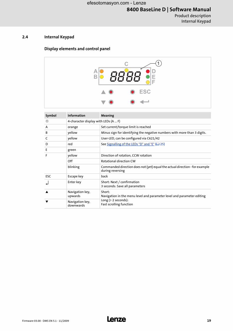
2.4 Internal Keypad
Display elements and control panel
Symbol Information Meaning
4-character display with LEDs (A ... F)
A orange Set current/torque limit is reached
B yellow Minus sign for identifying the negative numbers with more than 3 digits.
C yellow User-LED, can be configured via C621/42
D red See Signalling of the LEDs "D" and "E" ( 25)
E green
F yellow Direction of rotation, CCW rotation
Off Rotational direction CW
blinking Commanded direction does not (yet) equal the actual direction - for example during reversing
ESC Escape key back
↵ Enter key Short: Next / confirmation3 seconds: Save all parameters
Navigation key, upwards
Short: Navigation in the menu level and parameter level and parameter editingLong (> 2 seconds): Fast scrolling function
Navigation key, downwards
8888B
ESC
C
DEF
A
1
efesotomasyon.com - Lenze

8400 BaseLine D | Software ManualProduct descriptionInternal Keypad
20 L Firmware 03.00 - DMS EN 5.1 - 11/2009
efesotomasyon.com - Lenze

Firmware 03.00 - DMS EN 5.1 - 11/2009 L 21
8400 BaseLine D | Software ManualCommissioning
Before switching on
3 Commissioning
3.1 Before switching on
In order to prevent injury to persons or damage to material assets, check
before connecting the mains voltage:
– Wiring for completeness, short circuit, and earth fault
– The "emergency stop" function of the entire system
– The motor circuit configuration (star/delta) must be adapted to the output voltage of the controller
– The in-phase connection of the motor
the setting of the most important drive parameters before enabling the controller:
– Is the V/f rated frequency adapted to the motor circuit configuration?
– Are the drive parameters relevant for your application set correctly?
– Is the configuration of the analog and digital inputs and outputs adapted to the wiring?
Danger!
• Continuous operation at low field frequency with rated motor current may lead to thermal overload when self-ventilated machines are used. If required, motor temperature monitoring should be activated with C120
Motor temperature monitoring with I²xt ( 111).
• If an asynchronous motor with the nameplate data 400 V /230 V is delta-connected to a frequency inverter for 400 V mains supply voltage, set code C015 (V/f base frequency) to 87 Hz.
efesotomasyon.com - Lenze

8400 BaseLine D | Software ManualCommissioningBefore switching on
22 L Firmware 03.00 - DMS EN 5.1 - 11/2009
Tip!
In the Lenze setting, the "linear V/f characteristic" mode is set as motor control. Theparameter settings are preset so that, if the frequency inverter and the 50 Hzasynchronous machine match in terms of power, the controller is immediatelyready for operation without any further parameter setting expense and the motoroperates satisfactorily.
Recommendations for the following application cases:
• If the frequency inverter and the motor differ widely in terms of power, set Imax ( C022) to 2.0 IN(motor).
• If a high starting torque is required set Vmin boost ( C016) in motor idle state so that the rated motor current ( C058) flows at a field frequency of f = 3Hz.
• For noise optimisation set the switching frequency ( C018) to "3" (16 kHzsin var).
• If you need a high torque at low speed we recommend the control mode “vector control".
efesotomasyon.com - Lenze

Firmware 03.00 - DMS EN 5.1 - 11/2009 L 23
8400 BaseLine D | Software ManualCommissioning
Parameter setting and diagnosing directly at the controller
3.2 Parameter setting and diagnosing directly at the controller
Parameter setting
The front of the controller is provided with control elements which serve to access theparameters (also called codes) stored in the controller.
An overview with a corresponding description of the codes can be found in chapterParameter reference ( 175).
An overview of the menu structure of the internal keypad can be found in chapterMenu structure ( 24).
Diagnosing
The optical display of the internal keypad shows important status information of thecontroller by LEDs. The positions of the coloured LEDs are marked on the housing by letters.
More information on diagnostics options and messages can be found in the chaptersDiagnostics ( 25)
Messages ( 26)
The different controller states are described in chapterDevice states ( 48)
Tip!
Extensive parameter settings and configurations should be carried out with the L-force »Engineer«. If you want to use the L-force »Engineer«, the online help and thesoftware documentation for the controller will support you.
efesotomasyon.com - Lenze

8400 BaseLine D | Software ManualCommissioningParameter setting and diagnosing directly at the controller
24 L Firmware 03.00 - DMS EN 5.1 - 11/2009
3.2.1 Menu structure
Note!
• After switching on the controller, the internal keypad performs a quick self-test. All segments of the display flash for approx. 3 seconds. After that the display switches to the display which indicates the setpoint speed of the motor. The internal keypad is now operational.
• When the password protection is activated and no password is input, only the user menu is freely accessible. All other functions require the correct password.
Menu-0- , Access to all parameters selected by the user under C517.-1- , Access to all drive parameters.-2- , Access to parameters for fast commissioning with terminals.-3- , Access to parameters for fast commissioning with internal keypad.-4- , Access to motor control parameters.-5- , Access to diagnostic parameters.
-0-
� �
�
-1-
PASS
CAL
CAL/Stop
CAl/Err
bF
CL
FCL
Fst
dEC
br
PASS5 sec.
00010000
� �
....
....
� �
....
�
�
....
� �
�
....
���
� �
....
� �
-5-......
-2-
C_ _ _C_ _ _ c_ _ _c_ _ _
Status Password Menu Code Subcode Action
efesotomasyon.com - Lenze

Firmware 03.00 - DMS EN 5.1 - 11/2009 L 25
8400 BaseLine D | Software ManualCommissioning
Parameter setting and diagnosing directly at the controller
3.2.2 Diagnostics
[3-1] Signalling of the LEDs "D" and "E"
Symbol Information Meaning
4-character display with LEDs (A ... F)
A orange Set current/torque limit is reached
B yellow Minus sign for identifying the negative numbers bigger than 4 characters when the rotational direction has been reversed
C yellow User LED, configurable via C621/42, user-defined LED status
D red DRIVE ERROR, see the following table
E green Drive ready (no error occurred), see the following table
F yellow Direction of rotation, CCW rotation
Off Rotational direction CW
blinking Commanded direction is not equal to actual direction- for example during reversing
ESC Escape key Abort
↵ Enter key Confirmation / save parameter
upwards Short pressing: Navigation on menu and parameter level, parameter processing, long pressing (> 2 seconds): Quick scroll function
downwards
LED E = DRV-RDY LED D = DRV-ERR Status
OFF OFF "Init" state
OFF "ReadyToSwitchON" state
OFF "SwitchedON" state
OFF "OperationEnabled" state
Status display "Warning" The controller is ready to switch on, switched on or the operation is enabled and a warning is indicated.
OFF "Trouble" state
OFF "Fault" state
The symbols used to represent the LED states have the following meanings:
LED flashes once approx. every three seconds (slow flash)
LED flashes once approx. every 1.25 seconds ( flash)
LED flashes twice approx. every 1.25 seconds (double flash)
LED blinks every second
LED is permanently on
8888B
ESC
C
DEF
A
1
efesotomasyon.com - Lenze

8400 BaseLine D | Software ManualCommissioningParameter setting and diagnosing directly at the controller
26 L Firmware 03.00 - DMS EN 5.1 - 11/2009
3.2.3 Messages
The current status of the controller is constituted via
ƒ six coloured LEDs, see Signalling of the LEDs "D" and "E" ( 25)
ƒ messages:
Message Meaning
PASS Password input
CAL blinking Identification is in progress. Operation is not enabled yet.
CAL / Stop alternatively blinking Identification is ready to start
CAL / Err alternatively blinking Identification is not ready to start. Either C088, or C089, or C090 is 0.
bF blinking Identification error. Drive ID stored in EMP does not match the drive ID stored in the controller.
CL constant CL: ClampCurrent limit set in C022 is reached.
FCL constant Fast current limit value (higher than value set in C022) is reached
FSt constant Flying start is in progress
dec constant Deceleration is temporarily suspended because of higher bus voltage
br flashes during the hold time of the DC brake
DC brake is in progress
efesotomasyon.com - Lenze

Firmware 03.00 - DMS EN 5.1 - 11/2009 L 27
8400 BaseLine D | Software ManualCommissioning
Test commissioning
3.3 Test commissioning
Only a few parameters need to be adapted for the drive. Afterwards, the drive applicationcan be immediately controlled via the digital and analog inputs of the controller.
Tip!
For initial commissioning of the frequency inverter, the drive application ispreconfigured with the terminal control in the Lenze setting.
Further parameters can be used to assign the settings of the actual values to otherinterfaces.
Danger!
The controller is a source of danger which may lead to death or severe injury of persons.
To protect yourself and others against these dangers, observe the safety instructions before switching on the controller.
Please read the safety instructions provided in the 8400 Mounting Instructions and in the 8400 Hardware Manual. Both documents are supplied with the controller.
Commissioning step Action
Connect I/Os Enter the I/O connection • C007: Selection from table (-->terminals, 10)
Parameterise application Set speed setpoint • C011: Define reference speed in [rpm] • C012: Set acceleration time in [s] • C013: Set deceleration time in [s] • C105: Set QSP deceleration time in [s] • Further codes, e.g. jog values, TI times, brake management, etc.
Saving and testing Save parameter set ( 60) • Save parameter set 1 (-->C002/7 = 1) • Save all parameter sets (-->C002/11 = 1) • Save all parameter sets at the push of a button • Save all parameter changes automatically with mains failure protection
(---> C141/1)
efesotomasyon.com - Lenze

8400 BaseLine D | Software ManualCommissioningTest commissioning
28 L Firmware 03.00 - DMS EN 5.1 - 11/2009
Target of the "test commissioning"
For test and demonstration purposes, the motor is to start to rotate with as few wiring andsettings as possible in best time.
Keypad control or terminal control
First decide how the controller is to be controlled during test commissioning:
Test commissioning with keypad control ( 29)
Test commissioning with terminal control ( 31)
Tip!
The operation and commissioning of the internal keypad is described in theHardware Manual of the 8400 frequency inverter. The index of the CD attached tothe device as scope of supply contains the Hardware Manual saved as PDF.
A detailed description of how to use the integrated keypad can be found in thismanual in the chapter
Parameter setting and diagnosing directly at the controller ( 23)
efesotomasyon.com - Lenze

Firmware 03.00 - DMS EN 5.1 - 11/2009 L 29
8400 BaseLine D | Software ManualCommissioning
Test commissioning
3.3.1 Test commissioning with keypad control
Commissioning steps
1. Wire the power connections
Make use of the Mounting Instructions supplied with the frequency inverter to wire the power terminals according to the requirements of your device.
2. Wire the control connections
3. If you are sure that the state of the frequency inverter is as delivered from the manufacturer (Lenze setting), you can skip this commissioning step.If not, restore the Lenze setting on the frequency inverter:
[3-2] Setting / resetting the Lenze setting
Digital inputs at terminal X4 Assignment Info
RFR • Controller enableRFR = high
• Error resetHigh → low (edge-controlled)
• Select menu -1- (all parameters) • Press "Enter" key • Set code C002 • Press "Enter" key • Set subcode C001 • Press "Enter" key • Set value "01" • Press "Enter" key
DI1DI2DI3 RFRX4 24EDO1 12I AR A1U GNDDI4
-0-
� �
�
PASS5 sec.
0000
� �
....
....
� �
....
�
�
....
�
....
���� �
....C002 c001 01
-1-
8888
Status Password Menu Code Subcode Action
efesotomasyon.com - Lenze

8400 BaseLine D | Software ManualCommissioningTest commissioning
30 L Firmware 03.00 - DMS EN 5.1 - 11/2009
4. Set keypad control
5. Enable the controller:Set terminal X4/RFR to HIGH potential (X4/12I).
6. Use the keypad to change the motor velocity or the motor speed by selecting different fixed setpoints:
7. Save the settings with mains failure protection by entering the value "1" in code C002, subcode 7.
• Select menu -3- (quick commissioning with integrated keypad) • Press "Enter" key • Set code C007 • Press "Enter" key • Set value "20" • Press "Enter" key
Internal Keypad Code Subcode Motor speed
C728 3 CCW rotation:-199.9 % ..... 0 (from C011)
CW rotation:0 ... +199.9 % (from C011)
C051 - Observe • the actual speed value:
C051 • appearing messages
Diagnostics ( 25)
-0-
� �
�
-1-
PASS5 sec.5 sec.
0000
� �
....
....�
�
�
��
�
�
�
�
....
��
C...
C007
-2-
� �
� �
....
C002
0020-3-
0000
Status Password Menu Code Subcode Action
� �
��
C051
C728
199.9
�
�
....
�
�
c003 -199.9
efesotomasyon.com - Lenze

Firmware 03.00 - DMS EN 5.1 - 11/2009 L 31
8400 BaseLine D | Software ManualCommissioning
Test commissioning
3.3.2 Test commissioning with terminal control
Commissioning steps
1. Wire the power connectionsMake use of the Mounting Instructions supplied with the frequency inverter to carry out the power connections correctly and in accordance with the requirements of your device.
2. Wire the control connections
3. If you are sure that the state of the frequency inverter is as delivered from the manufacturer (Lenze setting), you can skip the following step.If not, restore the Lenze setting on the frequency inverter:
[3-3] Setting / resetting the Lenze setting
Wiring of the analog input at X4 Assignment Terminal control
A1U Setpoint selection10 V (= 100 %):1500 rpm (for 4-pole motor)
Interconnection of the digital inputs at X4 Assignment Terminal control
DI1 ... DI4: All active = high
RFR • Controller enable: RFR = high • Error reset:
High → low (edge-controlled)
DI1 DI1: Fixed frequency 1 ... fixed frequency 3, DI2: Fixed frequency 2 ... fixed frequency 3see table [3-1] ( 32)
DI2
DI3 DCB
DI4 Direction of rotation counter-clockwise/clockwise (CCW/CW)
• Select menu -1- (all parameters) • Press "Enter" key • Set code C002 • Press "Enter" key • Set subcode C001 • Press "Enter" key • Set value "01" • Press "Enter" key
DI1DI2DI3DI4 RFRX4 24EDO1 12I AR A1U GND
0 10V���
1k
10k
�
���
�
AR A1U GNDDI1DI2DI3 RFRX4 DO1 12I24E DI4
-0-
� �
�
PASS5 sec.
0000
� �
....
....
� �
....
�
�
....
�
....
���� �
....C002 c001 01
-1-
8888
Status Password Menu Code Subcode Action
efesotomasyon.com - Lenze

8400 BaseLine D | Software ManualCommissioningTest commissioning
32 L Firmware 03.00 - DMS EN 5.1 - 11/2009
4. Enable the controller:Set terminal X4/RFR to HIGH potential (X4/12I).
5. Use the potentiometer to change the motor velocity or the motor speed by selecting different fixed setpoints:
[3-1] Selection of fixed motor speeds via digital input terminals
6. Save the settings with mains failure protection by entering the value "1" in code C002, subcode 7.
DI2 DI1 Motor speed
0 0 Setpoint from potentiometer
0 1 40 % of C011 (reference speed)
1 0 60 % of C011 (reference speed)
1 1 80 % of C011 (reference speed)
Internal Keypad Code Subcode Motor speed
C051 - Observe • the actual speed value:
C051 • appearing messages
Diagnostics ( 25)
-2-
� �
C...
C051 xxxx
efesotomasyon.com - Lenze

Firmware 03.00 - DMS EN 5.1 - 11/2009 L 33
8400 BaseLine D | Software ManualCommissioning
Commissioning of the drive application with the »Engineer«
3.4 Commissioning of the drive application with the »Engineer«
The focus here is to commission a simple system constellation with a few components (seethe illustration below). During the step-by-step instructions, you will get more informationwhich is suitable for commissioning higher requirements.
[3-4] Block diagram for wiring the commissioning example for the drive application
Tip!
Execute the following subchapters step by step.
• Control terminals at plug connector X4:– GND, ground potential for analog and digital signals– AR, reference voltage (10 V) for analog signals– A1U, input 1 for analog signals (slider of the setpoint potentiometer R) – RFR, controller enable (CINH)
• Parameter setting and diagnostic terminal X6:– Communication between PC and controller
VU W X4X6
RFR 12IA1UARGND
M3~
i
RFR
8400 BaseLine
X61
X6
R
X4
efesotomasyon.com - Lenze

8400 BaseLine D | Software ManualCommissioningCommissioning of the drive application with the »Engineer«
34 L Firmware 03.00 - DMS EN 5.1 - 11/2009
When the device is commissioned using the »Engineer«, commissioning is carried out bymeans of dialogs and graphic user interfaces.
[3-5] The "Application parameter" tab as an example of a graphic user interface
3.4.1 Observe the safety measures
Observe all required safety measures before switching on the device. See also Beforeswitching on ( 21) .
efesotomasyon.com - Lenze

Firmware 03.00 - DMS EN 5.1 - 11/2009 L 35
8400 BaseLine D | Software ManualCommissioning
Commissioning of the drive application with the »Engineer«
3.4.2 Open the »Engineer«
When the »Engineer« is open, press the function key F1 to access the online help.
1. Execute start-up wizard
Using the start-up wizard and the information contained in the online help you first create a project in the »Engineer«
2. Establish an online connection
You establish a connection to the controller and its connected components, for instance via a diagnostic adapter.
When an online connection has been established between PC and device, the colour of the symbol in the project tree changes (right arrow) and "ONLINE" appears in the lower part of the workspace (right arrow). Click the highlighted symbol on the left:
[3-6] Reference to the online connection in the project tree and the working area
Note!
In the general part of the menu structure of the online help basic operations are described in detail. Please refer to the following chapters and make implementations as required:
• Chapter "Working with projects", e. g. "Creating a new project (select a component from the catalogue)", or "Creating a new project (Start search for connected devices)""
• Chapter "Project structure", e. g. select a motor, if possible, carry out motor identification run
• Chapter "Device functions in the online mode", e. g. "Setting a communication path and going online", establish connection between PC - device
efesotomasyon.com - Lenze
8400 BaseLine D | Software ManualCommissioningCommissioning of the drive application with the »Engineer«
36 L Firmware 03.00 - DMS EN 5.1 - 11/2009
3.4.3 Load the Lenze setting
In order to be able to take a defined state as a basis for this commissioning, you have toload the Lenze setting.
Start the action with C002/1 = 1.
Tip!
How to load the Lenze setting using the »Engineer« is described in chapter LoadLenze setting ( 60).
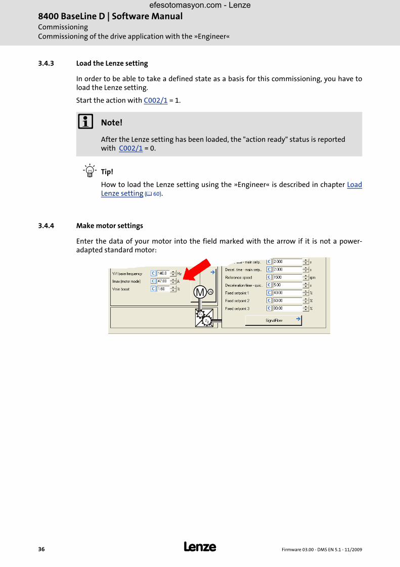
3.4.4 Make motor settings
Enter the data of your motor into the field marked with the arrow if it is not a power-adapted standard motor:
Note!
After the Lenze setting has been loaded, the "action ready" status is reported with C002/1 = 0.
efesotomasyon.com - Lenze

Firmware 03.00 - DMS EN 5.1 - 11/2009 L 37
8400 BaseLine D | Software ManualCommissioning
Commissioning of the drive application with the »Engineer«
3.4.5 Select control source
In this section, the origin of the signal source of the main setpoint is set. The selection ofthe signal source defines how the set technology application is to be controlled. On the"Application parameter" tab, for instance, (or with code C007) the main setpoint can bedefined as constant value via a digital input (terminal control).
The following options are available:
Terminal control
Control via keypad / PC
– Selection 20, keypad
– Selection 21, PC
In the commissioning example, the control source "Terminals 0" (Lenze setting) is selected (see arrow above).
Important parameters
Selection Name DI1 DI2 DI3 DI4
10 Terminal 0 JOG 1/3 JOG 2/3 DCB CCW
12 Terminal 2 JOG 1/3 JOG 2/3 QSP CCW
14 Terminal 11 CCW DCB MPotUp MPotDown
16 Terminal 16 JOG 1/3 JOG 2/3 CwQSP CcwQSP
Parameter INFO
C007 Select control mode
C242 Operating mode, selection for PID controller
C806 Use motor potentiometer yes / no
efesotomasyon.com - Lenze

8400 BaseLine D | Software ManualCommissioningCommissioning of the drive application with the »Engineer«
38 L Firmware 03.00 - DMS EN 5.1 - 11/2009
The device inputs and outputs called system blocks at Lenze are the interface of theapplication towards the peripherals of the controller, e.g. the digital and analog I/Os ("LS_DigitalInput, LS_DigitalOutput, LS_AnalogInput").
This is how you can follow, for instance, the origin of the main setpoint in the »Engineer«.Based on the "Application parameter" tab shown before, select the following path:
Click the "Signal flow" button. The dialog box "Overview --> Signal flow" appears (see below). Here you find the "Analog input 1" button (see marking). By the selection of the signal source (terminal control 0) this input is entered as source of the main setpoint:
[3-7] Signal sources of the TA "Speed closed-loop control", path: "Application parameters" tab --> "Signal flow" button
Click the "Main setpoint" button. A dialog window opens which contains further details on the origin(terminal X4/A1U) and parameter setting (offset, C026 / gain, C027):
efesotomasyon.com - Lenze
Firmware 03.00 - DMS EN 5.1 - 11/2009 L 39
8400 BaseLine D | Software ManualCommissioning
Commissioning of the drive application with the »Engineer«
An overview of the inputs and outputs assigned as a function of the control source can befound in a configuration table in the chapter Pre-assignment of the drive application( 146).
The configuration table contains a selection for the most frequently used signals so that aquick commissioning with only a few operator control action is possible. If the describedpre-assignment of the application block is not suitable for the drive task, select code C007= "0" to implement an individual configuration by means of the FB editor.
This allows for easy commissioning of the application, e.g. together with the setpoint boxavailable in the Lenze accessories program.
3.4.6 Start program
RFR = TRUE: Enable controller
The setpoint potentiometer ("R", see graphics [3-4]) serves to vary the speed.
efesotomasyon.com - Lenze

8400 BaseLine D | Software ManualCommissioningCommissioning of the drive application with the »Engineer«
40 L Firmware 03.00 - DMS EN 5.1 - 11/2009
3.4.7 Diagnostics
Why does the motor not rotate?
If the motor does not move contrary to expectations after the last commissioning step, werecommend the following systematic way to find out the reason for it.
1. Check the signal flow for plausible setpoints
2. Check setpoint sources
• Click the "Drive control" button (see illustration) of the "Diagnostics" tab
The appearing view is a complete summary of all control sources having an impact on the controller:
[3-8] Diagnostics options for drive control
Tip!
This information can also be displayed by the internal keypad. For this call thecodes specified in the header of the table.
Control sources which set the drive to controller inhibit Control sources which set the drive to quick stop / Diverse status information
efesotomasyon.com - Lenze

Firmware 03.00 - DMS EN 5.1 - 11/2009 L 41
8400 BaseLine D | Software ManualCommissioning
Password protection
3.5 Password protection
The controller offers the option to protect the unauthorised access to the menu level byassigning a password. The following sections describe how to create, change, or delete thepassword protection and how to access the menu level via the password:
Entry of a password not available yet (delivery status) ( 42)
Delete or change available password ( 43)
Access password-protected controller without knowing the password ( 44)
Reach password-protected menu level with knowing the password ( 45)
For this proceed step by step. The graphics shown above contain a program overview andthe required steps.
The meaning of the menus and the related menu levels are described in the chapter Menu structure ( 24).
efesotomasyon.com - Lenze

8400 BaseLine D | Software ManualCommissioningPassword protection
42 L Firmware 03.00 - DMS EN 5.1 - 11/2009
3.5.1 Entry of a password not available yet
This information is required if you want to create the password protection for e.g. acontroller in default status.
[3-9] Enter password and confirm it
[3-10] Save password with mains failure protection
8888
-0-
� �
-1-
PASS
PASS
5 s
0000
� �
....
8888PASS
� �� �
� �� �
��
C... c...
C094 c007
C002 c001
00
Status Password Menu Code Subcode Action
Action Display INFO Graphics
Mains on 00 After the mains has been switched on, "00" is displayed [3-9]
↵ -0- Without password protection you have free access from here to all parameters and menu levels
-1-
↵ C002
C094 Press until C094 appears
↵ 00 00 is blinking, i.e. entry is possible
<8888> Entry of a password from 01 .... 9999
↵ C094 Password confirmed
01
� �� �
� �� �
��
C... c...
C094 c007
C002 c001
00
Status Password Menu Code Subcode Action
Action Display INFO Graphics
C002 Scroll down until C002 has been reached [3-10]
↵ c001 Subcode level reached
C007
↵ 00 00 is blinking
"01" 01 Enter "1", confirm with ↵ , i.e. password is saved with failure protection
efesotomasyon.com - Lenze

Firmware 03.00 - DMS EN 5.1 - 11/2009 L 43
8400 BaseLine D | Software ManualCommissioning
Password protection
3.5.2 Delete or change available password
[3-11] Call available password
-0-
� �
-1-
PASS
0.5 s
0000
8888
� �
00PASS
� �� �
� �� �
C... c...
C094 c007
C002 c001
8888
Status Password Menu Code Subcode Action
Action Display Info Graphics
Mains on 00 [3-11]
↵ ... PASS .... 0000
First PASS appears, then 0000
<8888> Enter password
↵ -0- Ready to delete or change the password
-1-
↵ C002
C094 Press until C094 appears
↵ <8888> Available password is blinking
<8888>0000
New password: Set with orDelete password: Set with to "0000"
↵ C094 Password confirmed
Save Save password with mains failure protection ( 42) [3-10]
efesotomasyon.com - Lenze

8400 BaseLine D | Software ManualCommissioningPassword protection
44 L Firmware 03.00 - DMS EN 5.1 - 11/2009
3.5.3 Access password-protected controller without knowing the password
The codes of the password-protected controller can only be accessed in a restricted way.The accessible codes can be defined with C517.
[3-12] Limited parameter range without knowing the password
-0-
� �
...
PASS
0.5 s
0000
8888
� �
00PASS
� �
C...
C517
C051
Status Password Menu Code Subcode Action
Action Display INFO
Mains on 00
↵ ... PASS .... 0000 First PASS appears, then 0000
↵ <8888> The password cannot be entered correctly since the password is not known or has been entered wrongly.Only those codes appear which have been enabled for the "unauthorised" access. The range of these codes can be defined in the 20 subcodes of C517.The Lenze setting of C517 contains the following codes:C051, C053, C054, C061, C137, C011, C039, C012, C013, C015, C016, C022, C120, C087, C099.
efesotomasyon.com - Lenze

Firmware 03.00 - DMS EN 5.1 - 11/2009 L 45
8400 BaseLine D | Software ManualCommissioning
Password protection
3.5.4 Reach password-protected menu level with knowing the password
[3-13] Reaching the menu level with knowing the password
-0-
� �
...
PASS
0.5 s
0000
8888
� �
00PASS
� �
C...
C002
Status Password Menu Code Subcode Action
Action Display INFO
Mains on 00
↵ ... PASS .... 0000 First PASS appears, then 0000
<8888> Enter password
↵ -0- All menu levels can be accessed without any restrictions.
efesotomasyon.com - Lenze

8400 BaseLine D | Software ManualCommissioningPassword protection
46 L Firmware 03.00 - DMS EN 5.1 - 11/2009
efesotomasyon.com - Lenze

Firmware 03.00 - DMS EN 5.1 - 11/2009 L 47
8400 BaseLine D | Software ManualDrive control (DCTRL)
4 Drive control (DCTRL)
This chapter gives information about the device function "Drive control DCTRL". This devicefunction serves to control the controller into defined states and retrieve status informationvia the system block LS_DriveInterface:
The device displays status information in different ways
– as optical display via front LEDs to signalise the operating status,see chapter Diagnostics ( 25).
– as text message in the Engineer.
– as process signal at the output of the system block LS_DriveInterface
– as diagnostic parameter
The operating states of the controller are based on the DS402 standard. Device states ( 48)
efesotomasyon.com - Lenze
8400 BaseLine D | Software ManualDrive control (DCTRL)Device states
48 L Firmware 03.00 - DMS EN 5.1 - 11/2009
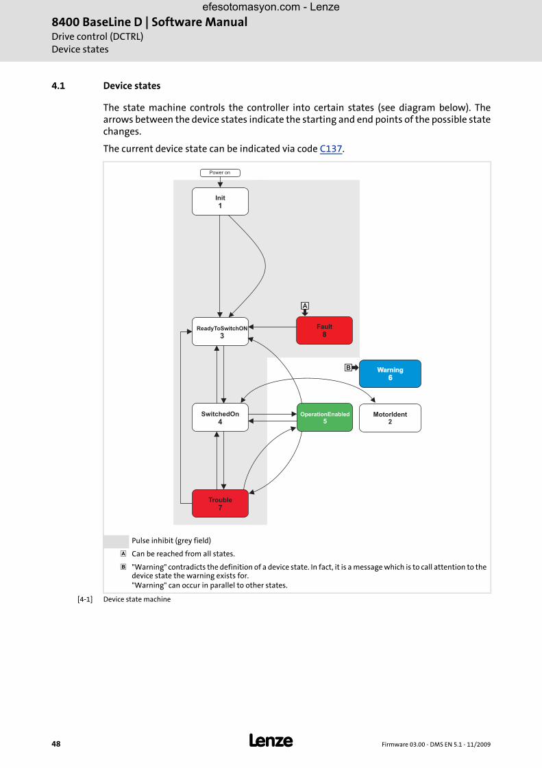
4.1 Device states
The state machine controls the controller into certain states (see diagram below). Thearrows between the device states indicate the starting and end points of the possible statechanges.
The current device state can be indicated via code C137.
[4-1] Device state machine
Pulse inhibit (grey field)
Can be reached from all states.
"Warning" contradicts the definition of a device state. In fact, it is a message which is to call attention to the device state the warning exists for."Warning" can occur in parallel to other states.
ReadyToSwitchON
3
Init
1
SwitchedOn
4OperationEnabled
5
Trouble
7
Fault
8
Warning
6Warning
6
MotorIdent2
�
�
Power on
efesotomasyon.com - Lenze

Firmware 03.00 - DMS EN 5.1 - 11/2009 L 49
8400 BaseLine D | Software ManualDrive control (DCTRL)
Device states
4.1.1 "Init" state
In this state
• the controller is immediately after switching on mains power.
• the operating system is initialised.
• all device components (memory module, power section, etc.) are identified.
The inverter is inhibited, i.e. the motor terminals (U, V, W) of the inverter are deenergised.
The digital and analog inputs are not yet evaluated at this time.
The communication interfaces (e.g. diagnostic interface) are not yet working.
The application is not yet processed.
The monitoring functions are not yet active.
The controller cannot be parameterised yet and no device commands can be executed.
When the power section is identified, it is checked first if it is switched on or if the requiredvoltage is within the tolerance zone. In case of undervoltage in the DC bus, the controllerchanges to the "Trouble" or "Fault" state depending on the configuration.
LED DRIVE READY LED DRIVE ERROR Display in C137
OFF OFF 1: Initialisation active
efesotomasyon.com - Lenze

8400 BaseLine D | Software ManualDrive control (DCTRL)Device states
50 L Firmware 03.00 - DMS EN 5.1 - 11/2009
4.1.2 "MotorIdent" status
8400 frequency inverters are provided with a function that automatically identifies themotor parameters, see the functional description Motor data identification .
The "MotorIdent" device state can only be reached by the "SwitchON" device state andjumps back to it after the action is completed.
The following illustration shows under which conditions the state change is possible orcompleted:
[4-2] Conditions for the state change of the motor identification
While the motor parameters are being identified,
the application remains active
all system interfaces (IOs, bus systems, etc.) remain active
error monitoring remains active
the inverter is controlled independent of the setpoint sources.
Detailed description: Automatic motor parameter identification ( 93)
4.1.3 "SafeTorqueOff" state
LED DRIVE READY LED DRIVE ERROR Display in C00137
OFF MotorIdent
Stop!
During motor parameter identification, the controller does not respond to setpoint changes or control processes, (e.g. speed setpoints, QSP, torque limitations).
ReadyToSwitchON
3
C0002/23 = 1CINH = 1
MotorIdent2
&
Danger!
This state is only possible together with a connected safety module and an existing power section supply.
efesotomasyon.com - Lenze

Firmware 03.00 - DMS EN 5.1 - 11/2009 L 51
8400 BaseLine D | Software ManualDrive control (DCTRL)
Device states
4.1.4 "ReadyToSwitchON" state
This is the device state of the controller after the initialisation is completed!
The bus systems are running and the terminals and encoders are evaluated.
The monitoring modes are active.
The controller can be parameterised.
The application is executable.
Auto-start option C00142 = 1: Auto restart inhibited after power-up
When the auto-start option C00142 = 1 (inhibit when "Mains on", Lenze setting) has been selected, the controller inhibit must always be cancelled after power-up so that the controller can change from the "Device is ready to switch on" to the "Device is switched on":
[4-3] State change when auto restart is inhibited (C00142 = "1")
LED DRIVE READY LED DRIVE ERROR Display in C00137
OFF ReadyToSwitchON
Controller pulses are inhibitedController pulses are enabled
With controller inhibit at power-upWithout controller inhibit at power-up
RFR�
� �
RFR
RFR
RFR
t
t
�
Initialisation Switched on OperationReady to switch on
Initialisation Switched on OperationReady to switch on
efesotomasyon.com - Lenze

8400 BaseLine D | Software ManualDrive control (DCTRL)Device states
52 L Firmware 03.00 - DMS EN 5.1 - 11/2009
Auto-start option C00142 = 0: Auto restart is enabled after power-up
The following illustration shows the state changes for the auto-start option C00142 = 0 as a function of the controller inhibit:
[4-4] State change when auto restart is enabled (C00142 = "0")
Tip!
Code C00142 can also be used to configure that the controller inhibits the auto-start function if
• there is a "Trouble" error status or
• a "Fault" error status or
• an undervoltage has been detected
Controller pulses are inhibitedController pulses are enabled
With controller inhibit at power-upWithout controller inhibit during power-up
RFR�
� �
RFR
RFR
RFR
t
t
�
Initialisation Switched on OperationReady to switch on
OperationInitialisation Switched onReady to switch on
efesotomasyon.com - Lenze

Firmware 03.00 - DMS EN 5.1 - 11/2009 L 53
8400 BaseLine D | Software ManualDrive control (DCTRL)
Device states
4.1.5 "SwitchedON" state
This is the drive's device state if the DC-bus voltage is applied and the controller is stillinhibited by the user (controller inhibit). The reason for the controller inhibit (CINH) isdisplayed in C00158.
The bus systems are running and the terminals and encoders are evaluated.
The monitoring modes are active.
The application is executable.
When the controller is enabled, the motor generates a torque.
4.1.6 "OperationEnabled" state
In this device state, the motor follows the setpoint defined in the application.
4.1.7 Status display "Warning"
This display may appear in parallel with all device states if a monitoring mode responds forwhich the "Warning" or "Warning locked" error responses have been parameterised.
LED DRIVE READY LED DRIVE ERROR Display in C00137
OFF SwitchedON
LED DRIVE READY LED DRIVE ERROR Display in C00137
OFF OperationEnable
LED DRIVE READY LED DRIVE ERROR Display in C00137
Warning
efesotomasyon.com - Lenze
8400 BaseLine D | Software ManualDrive control (DCTRL)Device states
54 L Firmware 03.00 - DMS EN 5.1 - 11/2009
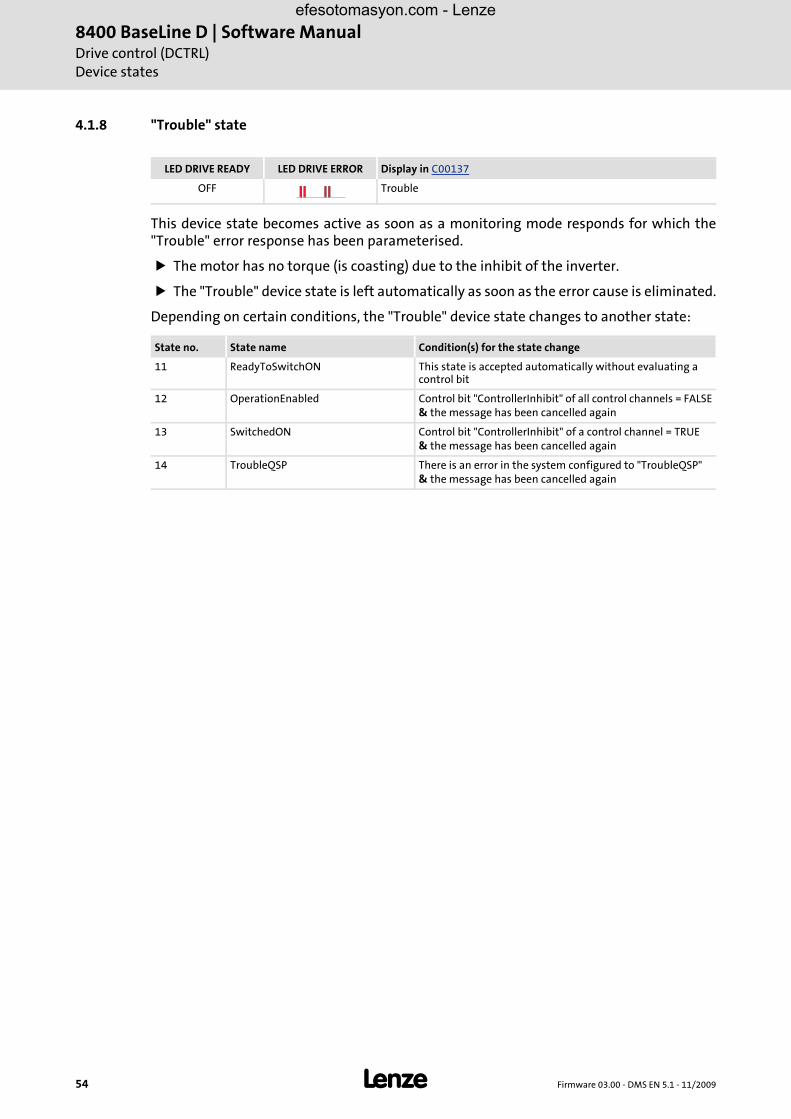
4.1.8 "Trouble" state
This device state becomes active as soon as a monitoring mode responds for which the"Trouble" error response has been parameterised.
The motor has no torque (is coasting) due to the inhibit of the inverter.
The "Trouble" device state is left automatically as soon as the error cause is eliminated.
Depending on certain conditions, the "Trouble" device state changes to another state:
LED DRIVE READY LED DRIVE ERROR Display in C00137
OFF Trouble
State no. State name Condition(s) for the state change
11 ReadyToSwitchON This state is accepted automatically without evaluating a control bit
12 OperationEnabled Control bit "ControllerInhibit" of all control channels = FALSE& the message has been cancelled again
13 SwitchedON Control bit "ControllerInhibit" of a control channel = TRUE& the message has been cancelled again
14 TroubleQSP There is an error in the system configured to "TroubleQSP"& the message has been cancelled again
efesotomasyon.com - Lenze

Firmware 03.00 - DMS EN 5.1 - 11/2009 L 55
8400 BaseLine D | Software ManualDrive control (DCTRL)
Device states
4.1.9 "Fault" state
This device state becomes active as soon as a monitoring mode responds for which theerror response "Fault" has been parameterised.
The motor has no torque (is coasting) due to the inhibit of the inverter.
To exit the device state, "Fail reset" must be set.
After "Fail Reset" has been executed, the state changes to "ReadyToSwitchON".
Tip!
For more information on the error messages, see
Error messages of the operating system ( 134) or
Cause & possible remedies ( 138).
LED DRIVE READY LED DRIVE ERROR Display in C00137
OFF Fault
Note!
If there is an undervoltage in the DC bus (error message "LU") of the frequency inverter, the device changes to the "Trouble" state.
An additionally occurring error with higher priority causes the drive to change to the "Fault" state.
According to the Device state machine ( 48) the device changes to the "ReadyToSwitchOn" state after the error has been acknowledged, although the undervoltage is still available!
efesotomasyon.com - Lenze

8400 BaseLine D | Software ManualDrive control (DCTRL)Controller commands
56 L Firmware 03.00 - DMS EN 5.1 - 11/2009
4.2 Controller commands
4.2.1 General information
The commands in the subcodes of code C002 enable
the direct control of the controller. This comprises e.g. the following subcodes:
– 16, enable controller (CINH)"0" = controller is inhibited by software, "1" = enable via external switch
– 17, quick stop (QSP)"0" = activate QSP via external switch, "1" = activate QSP via software
the management of parameter sets and diagnosis services:
– Parameter set management, e.g. subcode 7, load parameter set 1
– Logbook management
– Error management
– Identification, e.g. motor parameters, inverter characteristic
Regarding the execution of the commands, there are two different groups:
1. Commands with immediate control effect (e.g. quick stop). These commands contain the static status information ON or OFF.
2. Commands with a pure command nature
The subcodes of the second group do not execute the action immediately. However, afterthe command is written, they deliver dynamic status information and thus demonstratethe command progress:
After the activation value (1: On / start) is written, it can be read until the following stateis reported:
"2": Busy and then > (0: Off / ready)
If a problem occurs during the execution of a device command, the returned information is
"4": Action cancelledor
"5": No access
efesotomasyon.com - Lenze

Firmware 03.00 - DMS EN 5.1 - 11/2009 L 57
8400 BaseLine D | Software ManualDrive control (DCTRL)
Controller commands
Certain commands can only be executed if the controller is inhibited, e.g.
• Load Lenze setting C002/1
• Load parameter set 1, C002/7
• Identify motor parameters C002/23
If these commands are executed without the controller being inhibited, the returnedinformation is:
"6": No access controller inhibit
Note!
C003 always displays the last error occurred in the form of an error number, if e.g. a command should fail.
Status display for device command ( 59)
efesotomasyon.com - Lenze

8400 BaseLine D | Software ManualDrive control (DCTRL)Controller commands
58 L Firmware 03.00 - DMS EN 5.1 - 11/2009
The following subchapters describe the device commands in the controller in detail.
With an online connection, the controller commands can be activated from the »Engineer«by selecting the corresponding command on the Parameters tab under C002. As analternative, the controller commands can be activated via the internal keypad.
Tip!
Many frequently required device commands (e.g. "Save parameters") can beexecuted via the toolbar icons of the »Engineer«.
Stop!
Before switching off the supply voltage after transmitting a device command via C002, use this code to check that the device command has been completed successfully, see C002/7 (save parameter set 1) or chapter Save parameter set ( 60). This particularly applies to device commands used for saving data in the memory module of the device. If the saving process cannot be completed successfully, data inconsistency can occur in the memory module.
Note!
Controller commands that can be executed via the toolbar of the »Engineer« always affect the element currently selected in the Project view including all subelements.
• If no controller, but e.g. a system module is selected in the Project view, the
corresponding device command (e.g. load parameter set ) will be activated in all lower-level controllers having an online connection with the »Engineer«.
For the commands described in the following subsections, the controller must be selected in the Project view.
efesotomasyon.com - Lenze

Firmware 03.00 - DMS EN 5.1 - 11/2009 L 59
8400 BaseLine D | Software ManualDrive control (DCTRL)
Controller commands
4.2.2 Overview of device commands
[4-1] Overview of device commands, "CINH": controller must be inhibited
4.2.3 Status display for device command
For almost all device commands, the status is displayed via C002, e.g. whether the devicecommand has been executed successfully or an error has occurred during the execution. Ifan error has occurred (i.e. C002 provides the value "4": Failed on readback), you can read outthe parameter 3 for detailed error diagnosis. C003 displays the status of the last executeddevice command.
The device commands which support the status display via C002 can be obtained from the table in the previous chapter "Overview of device commands" (see column "Static / command").
The display under C003 remains unchanged if a device command does not support the status display.
Code C002 INFO Static/comman
dSubcode Controller command
1 Load Lenze setting Load Lenze setting ( 60) CINH
2 Load parameter set 1 "Load" means: The data is transferred from the memory module to the device
-
3...6 Reserved -
7 Save parameter set 1 "Save" means: The data is transferred from the device to the memory module
-
8...10 Reserved -
11 Save all parameter sets All data is transferred from the device to the memory module
-
12...15 Reserved -
16 Enable controller Set/remove controller inhibit ( 70) -
17 Activate quick stop Activate/deactivate quick stop function (QSP) ( 71)
-
18 Reserved -
19 Reset error Reset of error message ( 136) -
20 Reserved -
21 Delete logbook Logbook ( 129) CINH
22 Reserved -
23 Identify motor parameters CINH
24 Reserved -
25 Reserved -
26 CAN ResetNode CINH
27...32 Reserved -
efesotomasyon.com - Lenze

8400 BaseLine D | Software ManualDrive control (DCTRL)Controller commands
60 L Firmware 03.00 - DMS EN 5.1 - 11/2009
4.2.4 Load Lenze setting
This controller command resets the parameter settings to the Lenze setting. All parameterchanges get lost.
Only possible when controller is inhibited.
This controller command has an effect on the settings of the parameters of the operating system and application.
How to load the Lenze setting:
1. Click the icon to set the controller inhibit.
• A confirmation prompt is displayed asking you if the controller should really be inhibited.
2. Confirm confirmation prompt with Yes to continue the action.
3. Execute device command C002/1 = 1: "On / Activate".
4.2.5 Save parameter set
Controller parameter changes made via the »Engineer« or internal keypad will get lostafter mains switching of the controller unless the settings have been explicitly saved withthe corresponding controller command in the memory module of the controller.
You have various opportunities to prevent a data loss by saving the parameter sets in thememory module:
Quick saving at the push of a button
Automatic saving of parameter changes
Manual saving of parameter sets
efesotomasyon.com - Lenze

Firmware 03.00 - DMS EN 5.1 - 11/2009 L 61
8400 BaseLine D | Software ManualDrive control (DCTRL)
Controller commands
Quick saving at the push of a button
This function serves to save all available parameter sets at any time by pushing a button.
Automatic saving of parameter changes
When you activate the automatic saving function with code C141/1, every parameterchange is saved in the memory module. Thus, manual saving of parameter sets is notrequired anymore.
Manual saving of parameter sets
This procedure serves to save either the parameter set 1 or all parameter sets via thesubcodes of code C002.
When C002/7 = "1", the parameter set 1 is saved in the controller.
When C002/11 = "1", all parameter sets are saved in the controller.
4.2.6 Load parameter set
Activation of this device command reloads all parameters from the memory module intothe controller. All parameter changes made since the parameter set has been saved lastwill get lost.
Only possible when the controller is inhibited
This device command has an effect on the settings of the parameters of the operating system, application, and module.
How to reload the starting parameters from the memory module:
How to proceed:
1. Keep the entry button pressed for 3 seconds.
2. When "SAVE" is blinking, your parameter sets are saved with mains failure protection.
3. You can continue your work. "SAVE" will disappear from the display after approximately 2 seconds.
Stop!
Activating this function is not permissible if parameters are changed very frequently (e.g. in case of cyclic writing of parameters via a bus system).
The maximum service life of the memory module amounts to one million writing cycles. Make sure that this value will not be reached.
B
ESC
C
DEF
A
8888
3 sec
SAVE
efesotomasyon.com - Lenze

8400 BaseLine D | Software ManualDrive control (DCTRL)Controller commands
62 L Firmware 03.00 - DMS EN 5.1 - 11/2009
1. Click the symbol to inhibit the controller and stop the application currently running.
• A confirmation prompt is displayed asking you if the controller should really be inhibited and the application currently running should be stopped.
2. Confirm confirmation prompt with Yes to continue the action.
3. Execute device command C002 / 2 = "1", Load parameter set 1.
efesotomasyon.com - Lenze

Firmware 03.00 - DMS EN 5.1 - 11/2009 L 63
8400 BaseLine D | Software ManualDrive control (DCTRL)
System block "LS_DriveInterface"
4.3 System block "LS_DriveInterface"
The following graphic displays the functions of the LS_DriveInterface system block:
10
LS_DriveInterface
X5/28
bFailReset
bCInh
bStatus_Bit0
bStatus_Bit2
bStatus_Bit3
bStatus_Bit4
bStatus_Bit5
PowerDisabled
ActSpeedIsZero
ControllerInhibit
StatusCodeBit1
StatusCodeBit2
StatusCodeBit3
StatusCodeBit4
Warning
TroublebStatus_Bit14
bStatus_Bit15
0
1
2
3
4
5
6
7
8
9
10
11
12
13
14
15
Status
C00002 / 16
.........
C00002 / 17C00002 / 19
QSP
Disable
CINH
Fail-RESET
Fail-SET
wStateDetermFailNoLow
wStateDetermFailNoHigh
bInit
bReady
bReadyToSwitchOn
bOperationEnable
bWarning
bTrouble
bFault
bImpIsActive
bCInhIsActive
bCwCcw
bNactCompare
{
{
{
{
{
Bit1
Bit 2
Bit3
Bit14
Bit7
3
1
4 5
7
8
DriveCommands
}C00002/17
C00002/16
C00002/19
efesotomasyon.com - Lenze

8400 BaseLine D | Software ManualDrive control (DCTRL)System block "LS_DriveInterface"
64 L Firmware 03.00 - DMS EN 5.1 - 11/2009
Inputs
Outputs
IdentifierDIS code | data type
Value/meaning
bCInhBOOL
Set/remove controller inhibit ( 70)
True The controller is set to the SwitchedON state.
FALSE The controller is set to the OperationEnabled state.
bFailResetBOOL
Reset of error message ( 136)
True The current error is reset.
FALSE The current error is not reset.
bStatus_Bit0bStatus_Bit2bStatus_Bit3bStatus_Bit4bStatus_Bit5bStatus_Bit14bStatus_Bit15
BOOL
Freely assignable bit positions of the controller's status word.You can use these bit positions for returning information to the higher-level control (e.g. IPC).
IdentifierDIS code | data type
Value/meaning
wDeviceStatusWordWORD
Status word of the controller.The status word contains all information required for controlling the controller. The process data word is sent to the higher-level control via a port block.
wStateDetermNoLowWORD
Display of the state-determining error (low)
wStateDetermNoHighWORD
Display of the state-determining error (high)
*) all BOOL
TrueState control of the controller is in state:
bInit *) State control of the controller is in state: • Init
bSafeTorqueOff *) State control of the controller is in state: • SafeTorqueOff
bReady *) State control of the controller is in state: • Ready
bReadyToSwitchOn *) State control of the controller is in state: • ReadyToSwitchON
bOperationEnable *) State control of the controller is in state: • OperationEnable
bWarning *) State control of the controller is in state: • Warning
bTrouble *) State control of the controller is in state: • OperationEnable
bFail *) State control of the controller is in state: • Fault
bSystemFail *) State control of the controller is in state: • SystemFail
bImpIsActive Pulse inhibit is active
bCInhIsActive True Controller inhibit is active
efesotomasyon.com - Lenze

Firmware 03.00 - DMS EN 5.1 - 11/2009 L 65
8400 BaseLine D | Software ManualDrive control (DCTRL)
System block "LS_DriveInterface"
Status word output
[4-2] Status word of the controller
[4-3] Extended status word of the controller
bCwCcw True Motor rotates in CCW direction
bNactCompare For open-loop operation: Speed setpoint = comparison value C024For closed-loop operation: Actual speed value = comparison value C024
Bit Function INFO
0 FreeStatusBit0
1 PowerDisabled Inverter control is inhibited (IMP)
2 FreeStatusBit2 Function depends on the application selected
3 FreeStatusBit3
4 FreeStatusBit4
5 FreeStatusBit5
6 ActSpeedIsZero Actual speed = 0
7 ControllerInhibit Controller inhibit is active
8 StatusCodeBit0 Status ID (bit-coded)
9 StatusCodeBit1
10 StatusCodeBit2
11 StatusCodeBit3
12 Warning
13 Trouble
14 FreeStatusBit14 Function depends on the application selected
15 FreeStatusBit15
IdentifierDIS code | data type
Value/meaning
Bit Function INFO
0 Fail
1 M_max
2 I_max
efesotomasyon.com - Lenze

8400 BaseLine D | Software ManualDrive control (DCTRL)Parameter setting
66 L Firmware 03.00 - DMS EN 5.1 - 11/2009
4.4 Parameter setting
4.4.1 General information
The controller can be adapted to a specific task by means of parameters. There are differentways to parameterise the controller:
Internal Keypad
Diagnostic interface
Parameter identification
Each parameter has
a parameter number which is unique within a drive system
a parameter text (»Engineer«)
specific attributes
– access type (read, write)
– data type
– limit values
– Lenze setting (factory-set scaling)
Division of the parameters into groups
The parameters are divided into the following function groups:
A. Setting parametersParameters for setting a device function, e.g. acceleration ramp, reference speed, max. motor current
B. Configuration parametersParameters for setting signal flows (signal interconnections) in the device, e.g. connection of the main setpoint to the analog input of the controller
C. Diagnostic parametersParameters for displaying device-internal process variables, e.g. the actual motor voltage or the control word. The diagnostic parameters have the attribute: read only.
efesotomasyon.com - Lenze

Firmware 03.00 - DMS EN 5.1 - 11/2009 L 67
8400 BaseLine D | Software ManualDrive control (DCTRL)
Parameter setting
Changing of parameters
Changing a parameter usually causes an immediate response of the controller.
The exceptions are certain device commands, e.g. C002/1 ("Load default setting") orsettings which might cause a critical state of the drive behaviour, e.g. a change of theactual speed value feedback configuration for closed-loop operation of the motor control.Such parameter changes are only accepted if the controller is inhibited, otherwise an errormessage is generated.
4.4.2 Saving of the parameters in the memory module
All parameters of the drive system are saved in the integrated memory module of thecontroller. This includes the parameters of the controller.
When the device is switched on, all parameters are automatically loaded from the memorymodule into the main memory of the controller.
In the event of a device replacement, the entire parameter data of an axis can be retainedby "taking along" the memory module, so that additional PC or internal keypad operationsare not required.
The controller is provided with one data set for all parameters, i.e. every setting andconfiguration parameter has a value.
Danger!
If you change configuration parameters, please observe that this causes the device-internal signal flow to change immediately which could result in a sudden change of setpoint sources (if, for instance, the signal source for the main setpoint is configured).
This can lead to an undesired behaviour at the motor shaft.
efesotomasyon.com - Lenze

8400 BaseLine D | Software ManualDrive control (DCTRL)Parameter setting
68 L Firmware 03.00 - DMS EN 5.1 - 11/2009
4.4.3 Handling of the memory module
In the delivery state, the Lenze setting of the parameters is stored in the memory module.
The following cases are distinguished regarding the handling:
• Delivery
– All devices are delivered with a plugged-on memory module.
– The memory module is available as a spare part - without any data.
• During operation
– The memory module (EPM) is required for operation.
– Parameter sets can be saved manually.
– Parameter sets can be loaded manually
• Replacement of the controllerIf the controller has to be replaced, observe the versions of the devices. Generally, the following applies:
– Before the data is transferred, the version is checked.
– Parameter sets of devices with V 1.0 can be processed on devices ≥ V 1.0(downward compatibility).
– If the parameter set versions of the two devices are not compatible, an error message (PS02/PS03, see Monitoring ( 132)) is generated.
– Parameters of a higher device version are not supported on devices with a lower version.
Danger!
If the memory module has been removed and the device is switched on, the connector pins are live and thus dangerous since the protection against contact is missing.
Stop!
The memory module must not be plugged in or unplugged during operation.
Note!
• Automatic saving is explicitly not supported because this significantly reduces the service life of the memory module.
• The 8400 BaseLine memory module is not compatible with the 8400 StateLine and 8400 HighLine memory modules.
• If the memory module has been removed, the "PS01" error message appears, see Monitoring ( 132)
efesotomasyon.com - Lenze

Firmware 03.00 - DMS EN 5.1 - 11/2009 L 69
8400 BaseLine D | Software ManualDrive control (DCTRL)
Parameter setting
4.4.4 Non-volatile saving of parameters
To save changed parameters permanently (i.e. safe against mains failure), the devicecommand C002/7 must be called separately. This command copies all parameters from theRAM of the device to the memory module.
This process may take some seconds.
The state of this saving process is indicated by the state of the corresponding devicecommand C002/7.
The device command C002/1 can be used to reset the controller to the Lenze setting of theparameters (delivery state).
4.4.5 Parameter set transfer
The »Engineer« PC program can be used to
save the parameter set to the memory module of the controller ,
read the parameter set from the controller
transfer the parameter set to the controller .
Note!
During the saving process
• Do not switch off the supply voltage.
• Do not pull off the memory module from the device.
efesotomasyon.com - Lenze

8400 BaseLine D | Software ManualDrive control (DCTRL)Parameter setting
70 L Firmware 03.00 - DMS EN 5.1 - 11/2009
4.4.6 Parameters for status display
4.4.7 Set/remove controller inhibit
Setting the controller inhibit inhibits the power stages in the controller and resets thespeed/current controllers of the motor control.
When the controller is inhibited, the status output bCInhActive of the system block LS_DriveInterface is set to TRUE.
The controller can be inhibited by different sources, e.g. via the digital input RFR, the bCInh input of the LS_DriveInterface system block or the "Inhibit controller" device command (C002/16 = "0").
The bit code under C158 shows the source that inhibited the controller.
Parameter INFO
C002 Device command transmission and execution status
C003 Status of last device command
C137 Device state
C150 Status word
C155 Status word 2
C158 Cause of controller inhibit (CINH)
C159 Cause of QSP
C165/1 Status-determining error as numeric text / actual error
C166/1 Error type, status-determining / actual error
C166/2 Subject area, status-determining / actual error
C166/3 Error ID, status-determining / actual error
C168 Status-determining error (display of 32-bit number)
Highlighted in grey = display parameter
efesotomasyon.com - Lenze

Firmware 03.00 - DMS EN 5.1 - 11/2009 L 71
8400 BaseLine D | Software ManualDrive control (DCTRL)
Activate/deactivate quick stop function (QSP)
4.5 Activate/deactivate quick stop function (QSP)
When the quick stop function is activated, it
disconnects the motor control from the selected setpoint and brakes the motor to standstill (nact = 0) along the quick stop ramp (C105).
sets the pulse inhibit (CINH) if the function auto DCB has been activated via C019.
Activation of the quick stop function
The quick stop function can be activated by different signal sources:
Device command C002/17, activate quick stop
Input signal at the LS_MotorInterface system block (motor control) set to TRUE.
Tip!
The cause of a quick stop can be displayed via the parameter C159.
efesotomasyon.com - Lenze

8400 BaseLine D | Software ManualDrive control (DCTRL)Activate/deactivate quick stop function (QSP)
72 L Firmware 03.00 - DMS EN 5.1 - 11/2009
efesotomasyon.com - Lenze

Firmware 03.00 - DMS EN 5.1 - 11/2009 L 73
8400 BaseLine D | Software ManualMotor control (MCTRL)
5 Motor control (MCTRL)
This chapter contains information on parameter setting of the internal motor control ofthe controller, i.e. this chapter describes
Control types and related signal flow diagrams
Motor selection
Parameter setting of the motor
Optimisation of the internal control loops of the motor control.
See also: Parameter setting of the V/f characteristic control ( 79)
Sensorless vector control (SLVC) ( 87)
efesotomasyon.com - Lenze

8400 BaseLine D | Software ManualMotor control (MCTRL)Selection of the operating mode
74 L Firmware 03.00 - DMS EN 5.1 - 11/2009
5.1 Selection of the operating mode
The motor control mode is defined with the selection of the operating mode, see C6:
Two different processes are available, which can be operated as follows regarding thespeed feedback:
V/f characteristic control ( 77)
– Without speed feedback, VFCplus: linear V/f characteristic (C6, value: 6)
– Without speed feedback, VFCplus: square-law V/f characteristic (C6, value: 8)
Sensorless vector control (SLVC) ( 87)
– without speed feedback, sensorless vector control (C006, value: 4)
V/f characteristic control
The V/f characteristic control is an operating mode for standard frequency inverterapplications based on a simple and robust control process. In addition to the operation ofmachines with linear or square-law load torque characteristic (e.g. fan), the control processis also suited for high-inertia systems thanks to the use of the autoboost function. Due tothe low parameterisation effort, easy and fast commissioning can be implemented forsuch applications.
efesotomasyon.com - Lenze
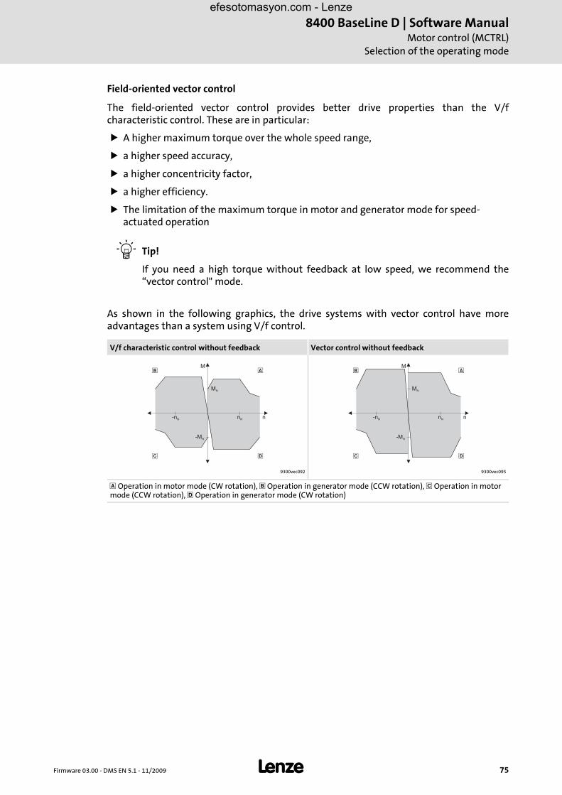
Firmware 03.00 - DMS EN 5.1 - 11/2009 L 75
8400 BaseLine D | Software ManualMotor control (MCTRL)
Selection of the operating mode
Field-oriented vector control
The field-oriented vector control provides better drive properties than the V/fcharacteristic control. These are in particular:
A higher maximum torque over the whole speed range,
a higher speed accuracy,
a higher concentricity factor,
a higher efficiency.
The limitation of the maximum torque in motor and generator mode for speed-actuated operation
Tip!
If you need a high torque without feedback at low speed, we recommend the“vector control" mode.
As shown in the following graphics, the drive systems with vector control have moreadvantages than a system using V/f control.
V/f characteristic control without feedback Vector control without feedback
9300vec092 9300vec095
Operation in motor mode (CW rotation), Operation in generator mode (CCW rotation), Operation in motor mode (CCW rotation), Operation in generator mode (CW rotation)
��
� �
nN
MN
M
-MN
-nN n
��
� �
nN
MN
M
-MN
-nN n
efesotomasyon.com - Lenze

8400 BaseLine D | Software ManualMotor control (MCTRL)Selection of the operating mode
76 L Firmware 03.00 - DMS EN 5.1 - 11/2009
To ease the selection of the operating mode (C006), the following table containsrecommendations and alternatives for standard applications.
Application Recommended Alternatively
Single drives
With constant load Linear V/f characteristic Vector control
With extremely alternating loads Vector control Linear V/f characteristic
With high starting duty Vector control Linear V/f characteristic
With speed control Linear V/f characteristic Linear V/f characteristic
Torque limitation Vector control -
With torque limitation (power control) Linear V/f characteristic Vector control
Three-phase reluctance motor Linear V/f characteristic -
Three-phase sliding rotor motor Linear V/f characteristic -
Three-phase AC motors with permanently assigned frequency/voltage characteristic
Linear V/f characteristic -
Pump and fan drives with quadratic load characteristic Square-law V/f characteristic
Linear V/f characteristic or vector control
Group drives (several motors connected to controller)
Identical motors and loads Linear V/f characteristic -
Different motors and/or alternating loads Linear V/f characteristic -
Simple hoists Linear V/f characteristic -
efesotomasyon.com - Lenze

Firmware 03.00 - DMS EN 5.1 - 11/2009 L 77
8400 BaseLine D | Software ManualMotor control (MCTRL)
Selection of the operating mode
5.1.1 V/f characteristic control
The control structure is shown, in simplified form, in the following illustration. For thecomplete representation, see
Signal flow ( 108).
Stop!
• The following must be observed when operating drives with square-law V/f characteristic:
– Please always check whether the corresponding drive is suitable for operation with a quadratic V/f characteristic!
– If your pump or fan drive is not suitable for operation with a quadratic V/f characteristic, either use the V/f characteristic control with linear V/f characteristic or the vector control mode.
• For adjustment, observe the thermal performance of the connected asynchronous motor at low output frequencies.
– Usually, standard asynchronous motors with insulation class B can be operated for a short time with their rated current in the frequency range 0 Hz ≤ f ≤ 25 Hz.
– Contact the motor manufacturer to get the exact setting values for the max. permissible motor current of self-ventilated motors in the lower speed range.
– If you select the quadratic V/f characteristic, we recommend to set a lower Vmin.
efesotomasyon.com - Lenze

8400 BaseLine D | Software ManualMotor control (MCTRL)Selection of the operating mode
78 L Firmware 03.00 - DMS EN 5.1 - 11/2009
In case of the V/f characteristic control, the motor voltage of the inverter is detected bymeans of a linear or square-law characteristic depending on the field frequency or motorspeed to be generated. The voltage follows a preselected characteristic.
[5-1] Principle of a linear and quadratic V/f characteristic
Generally, two different characteristic shapes can be defined:
Linear V/f characteristic for drives with a constantly running and speed-independent load torque
Quadratic characteristic for drives with a load torque increasing quadratically with the speed. Quadratic V/f characteristics are mainly used in centrifugal pumps and fan drives.
8400vec085 / 8400vec086
0 1
0
100 %
N
nn
Umin
Uout
0 1
0
100 %
N
nn
Umin
Uout
efesotomasyon.com - Lenze

Firmware 03.00 - DMS EN 5.1 - 11/2009 L 79
8400 BaseLine D | Software ManualMotor control (MCTRL)
Selection of the operating mode
5.1.1.1 Parameter setting of the V/f characteristic control
Overview of the relevant parameters
How to parameterise the V/f characteristic:
1. Select the operating mode " V/f characteristic control" with appropriate characteristic shape C006.
2. When using an asynchronous motor which deviates from the standard motor, having a different rated frequency than 50 Hz (star) / 87 Hz (delta) and a different number of pole pairs than 2:
• Enter nameplate data of the motor (at least rated speed, rated frequency and rated voltage)
3. If required, adapt the base frequency of the V/f characteristic C015
4. If required, rise the V/f characteristic by Vmin C016
See also: Setting the V/f base frequency ( 80)
Setting Vmin boost ( 81)
Parameter INFO
C006 Selection of the operating mode for V/f characteristic control without feedback with • value "6" for linear characteristic or • value "8" for quadratic characteristic
C011 Reference speed
C015 Base frequency
C016 Vmin boost
C018 Switching frequency
C021 Slip compensation
C022 Current limit (in motor mode)
C023 Current limit (in generator mode)
C073 Imax current controller gain
C074 Reset time Imax current controller
C909/1 /2 Maximum positive / negative speed
C910/1 /2 Maximum positive / negative output frequency
efesotomasyon.com - Lenze

8400 BaseLine D | Software ManualMotor control (MCTRL)Selection of the operating mode
80 L Firmware 03.00 - DMS EN 5.1 - 11/2009
Setting the V/f base frequency
The V/f base frequency determines the slope of the V/f characteristic and has considerableinfluence on the current, torque, and power performance of the motor.
– The setting in code C015 applies to all permissible mains voltages.
– Mains fluctuations or fluctuations of the DC-bus voltage (operation in generator mode) do not need to be considered when the code is set. They are automatically compensated by the internal mains voltage compensation of the device.
– Depending on the setting of C015 it may be necessary to adapt the reference speed C011 to be able to run through the whole motor speed range.
– The V/f base frequency is automatically calculated from the data stored in the motor nameplate by the motor parameter identification:
Typical values for the V/f base frequency C015:
• Vfrequency inverter:– Frequency inverter 400 V– Frequency inverter 230 V
• Vratedmot: Rated motor voltage depending on the connection method
• frated: Rated motor frequency
Frequency inverter 400 V Frequency inverter 230 V
Motor voltage [V]
Motor frequency [Hz]
Motor connection
C015 Motor voltage [V]
Motor frequency [Hz]
Motor connection
C015
230 / 400 50 50 Hz 230 50 50 Hz
220 / 380 50 52.6 Hz 220 / 380 50 52.3 Hz
280 / 480 60 50 Hz
400 / 690400
5050
50 Hz
230 / 400280 / 480400
506087
87 Hz
220 / 380 50 90.9 Hz
Note!
4-pole asynchronous motors, which are designed for a rated frequency of f = 50 Hz in star connection, can be operated in delta connection when being constantly excited up to f = 87 Hz.
• Advantages:
– Higher speed-setting range
– 73% higher power output in case of standard motors
• Motor current and motor power increase by the factor .
• The field weakening range starts above 87 Hz.
• Generally, this process can also be used with motors which have different numbers of pole pairs. In case of 2-pole asynchronous motors, the mechanical limit speed must be maintained.
C00015 Hz[ ]UFU V[ ]
UNMot V[ ]-------------------------- fNenn Hz[ ]⋅=
3
efesotomasyon.com - Lenze

Firmware 03.00 - DMS EN 5.1 - 11/2009 L 81
8400 BaseLine D | Software ManualMotor control (MCTRL)
Selection of the operating mode
Setting Vmin boost
The Vmin boost C016 of the motor voltage
serves to select a magnetising current required for asynchronous motors independent of the load.
is effective for output frequencies below the V/f base frequency
optimises the torque behaviour of the motor.
The general linear and quadratic V/f characteristics are shown in the followingillustrations. The illustrations show the impacts of the parameters used to adapt thecharacteristic shape.
The maximum motor voltage to be reached depends on the current mains voltage height.
[5-2] Representation of the linear V/f characteristic (on the left) and quadratic V/f characteristic (on the right)
How to adjust the Vmin boost:
1. Operate motor in idle state at approx. 6 % of the rated motor speed.
2. Increase Vmin until the following motor current is reached:
• Motor in short-time operation up to 0.5 nrated
with self-ventilated motors: Imotor ≈ Irated motor
with forced-ventilated motors: Imotor ≈ Irated motor
• Motor in continuous operation up to 0.5 nrated
with self-ventilated motors: Imotor ≈ 0.8 Irated motor
with forced ventilated motors: Imotor ≈ Irated motor
C00015
C00016
C000152
C000162
V [V]out
f [Hz]
V
(100 %)rmot
1/N/PE AC 264 V3/PE AC 550 V
1/N/PE AC 180 V3/PE AC 320 V
C00015
C00016
V [V]out
f [Hz]
V
(100 %)rmot
1/N/PE AC 264 V3/PE AC 550 V
1/N/PE AC 180 V3/PE AC 320 V
efesotomasyon.com - Lenze

8400 BaseLine D | Software ManualMotor control (MCTRL)Selection of the operating mode
82 L Firmware 03.00 - DMS EN 5.1 - 11/2009
Subsequent optimisation of the V/f characteristic control
The V/f characteristic control is generally ready for service. The options to subsequentlyadapt the V/f characteristic control is to adapt the drive behaviour.
Adaptation of the characteristic
– Each of the three characteristic shapes can be adapted to different load profiles or motors via several parameters, see e.g. C015, base frequency or C016, Vmin boost.
Adaptation of the drive behaviour
– Limitation of the maximum current C022 by a current controller (e.g. to prevent the motor from stalling or to limit to the maximum permissible motor current)
– Adaptation of the field frequency by a load-dependent slip compensation C021 (improved speed accuracy for systems without feedback)
Only the following drive behaviour requires an optimisation of the V/f characteristiccontrol:
Drive behaviour Remedy
Bad smooth running with low speeds, especially in case of operation with long motor cable
Carry out motor identification
Problems in case of high starting duty (great mass inertia)
Adapt Vmin boost C016 • Set the code so that a 0.8 ... 1-fold rated motor current
flows with a controller enabled and 5 ... 10% of the rated speed.
The drive does not follow the speed setpoint. The current controller intervenes in the set field frequency to limit the controller output current to the maximum current (C0022, C0023). Therefore • increase acceleration time / deceleration time C012,
C013 • Consider a sufficient magnetising time of the motor.
Depending on the motor power the magnetising time amounts to 0.1 ... 2 s
• increase permissible maximum current (in motor mode, in generator mode) C022, C023
For operation with C006 = 6:Insufficient speed constancy at high load (setpoint and motor speed are not proportional any more)
• Increase slip compensation C021. Important: unstable drive due to overcompensation!
• If cyclic load impulses (e.g. centrifugal pump) occur, a smooth motor characteristic is achieved by smaller values in C021 (possibly negative values)
Error messages "Peak current limitation clamp" (FCL), controller cannot follow dynamic processes, i.e. acceleration or deceleration times are too short regarding the load conditions
• Increase the gain of the Imax controller C073 • Reduce the integral-action time of the Imax controller
C074 • Increase the acceleration time C012 • Increase the deceleration time C013
efesotomasyon.com - Lenze

Firmware 03.00 - DMS EN 5.1 - 11/2009 L 83
8400 BaseLine D | Software ManualMotor control (MCTRL)
Selection of the operating mode
5.1.1.2 Optimisation of operational performance by slip compensation
Under load, the speed of an asynchronous machine decreases. This load-dependent speeddrop is called slip.
The slip can be compensated by setting C021 accordingly.
The slip compensation can be set automatically by entering the value calculated during the motor parameter identification into code C021.
The setting must be made manually when the motor parameter identification cannot be called up.
How to enter the slip compensation automatically:
1. Prepare the motor parameter identification by setting the following data taken from the motor nameplate:
• Rated motor power C081
• Rated motor speed C087
• Rated motor current C088
• Rated motor frequency C089
• Rated motor voltage C090
• Motor cos ϕ C091
2. Carry out the motor parameter identificationAutomatic motor parameter identification ( 93)
Note!
The slip compensation C021 is active in the V/f characteristic control mode and in the vector control mode (C6 = 4, 6, 8).
efesotomasyon.com - Lenze

8400 BaseLine D | Software ManualMotor control (MCTRL)Selection of the operating mode
84 L Firmware 03.00 - DMS EN 5.1 - 11/2009
How to set the slip compensation manually:
1. Calculate the slip compensation from the data of the motor nameplate:
[5-1] Calculation of the slip compensation from the motor data
2. Enter the result in code C021
3. When the drive is running, correct the code C021 until no load-dependent speed drop occurs anymore in the speed range between idle state and maximum load of the motor. The guide value for a correctly set slip compensation is as follows:
• Deviation from the rated motor speed ≤ 1% for the speed range of 10 % ... 100 % of the rated motor speed and loads ≤ rated motor torque.
• Greater deviations are possible in the field weakening range
Tip!
• If C021 is set too high, the drive may become unstable.
• Negative slip (C021 < 0) in conjunction with V/f characteristic control results in "smoother" drive behaviour at heavy load impulses or applications requiring a significant speed drop under load.
s Slip constant C021 [%]
nrsyn Synchronous motor speed [rpm]
nr Rated motor speed according to the motor nameplate [rpm]
fr Rated motor frequency according to the motor nameplate [Hz]
p Number of motor pole pairs (1, 2, 3 ..)
snrsyn nr–
nrsyn------------------------- 100%⋅=
nrsynfr 60⋅
p---------------=
efesotomasyon.com - Lenze

Firmware 03.00 - DMS EN 5.1 - 11/2009 L 85
8400 BaseLine D | Software ManualMotor control (MCTRL)
Selection of the operating mode
5.1.1.3 Optimisation of the Imax controller setting
efesotomasyon.com - Lenze

8400 BaseLine D | Software ManualMotor control (MCTRL)Selection of the operating mode
86 L Firmware 03.00 - DMS EN 5.1 - 11/2009
5.1.2 Vector control
Tip!
The complete structure of the vector control is shown in the Signal flow ( 108) .
Stop!
• The connected motor may be maximum one power class lower than the motor assigned to the controller.
• The operation with vector control is only permissible for a single drive.
• The operation with sensorless vector control (SLVC) is not permissible for hoists.
• A stable operation is only possible if one of the following three entries are made:
– Enter the nameplate data and equivalent circuit data of the motor (motor leakage inductance and mutual motor inductance, slip compensation and stator and rotor resistance) manually or
– enter the selected motor via the Lenze motor catalogue or
– enter the motor nameplate data and carry out the motor parameter identification.
• When you enter the motor nameplate data, take into account the phase connection implemented for the motor (star or delta connection). Only enter the data applying to the selected connection type.
efesotomasyon.com - Lenze

Firmware 03.00 - DMS EN 5.1 - 11/2009 L 87
8400 BaseLine D | Software ManualMotor control (MCTRL)
Selection of the operating mode
5.1.2.1 Sensorless vector control (SLVC)
The operating mode is based on the improved motor current control according to the LenzeFTC method.
Compared to the V/f characteristic control without feedback you will obtain
a higher maximum torque over the whole speed range,
a higher speed accuracy,
a higher concentricity factor,
a higher efficiency,
the implementation of torque-controlled operation with speed limitation,
the limitation of the maximum torque in motor and generator mode for speed-controlled operation.
efesotomasyon.com - Lenze

8400 BaseLine D | Software ManualMotor control (MCTRL)Selection of the operating mode
88 L Firmware 03.00 - DMS EN 5.1 - 11/2009
Speed control with torque limitation
A speed setpoint is selected and the drive system is operated in a speed-controlled manner.
The operational performance can be adapted in the following ways:
Overload limitation in the drive train: The torque is limited via the torque setpoints. Thus, for avoiding an overload in the drive train, nLimMotTorque C728/1 can be used to limit the torque in motor mode and nLimGenTorque C728/2 to limit the torque in generator mode.
Slip compensation:The slip of the machine is derived by means of the slip model. The influencing parameter is the slip compensation C021.
Note!
The codes for determining the torque limit values C728/1 for nLimMotTorque and C728/2 for nLimGenTorque have a setting range of -199.9 % ... 0 ... +199.9 %. To prevent sign problems or an unstable operation, the entered limit values are processed as absolute values.
efesotomasyon.com - Lenze

Firmware 03.00 - DMS EN 5.1 - 11/2009 L 89
8400 BaseLine D | Software ManualMotor control (MCTRL)
Selection of the operating mode
Overview of the relevant parameters
Parameter INFO
C6 Selection of the operating mode for V/f characteristic control without feedback with • value "6" for linear characteristic or • value "8" for quadratic characteristic
C011 Reference speed
C018 Switching frequency
C021 Slip compensation
C022 Current limit (in motor mode)
C023 Current limit (in generator mode)
C057 Maximum torque
C081 Rated motor power
C084 Motor stator resistance
C085 Motor stator leakage inductance
C087 Rated motor speed
C088 Rated motor current
C089 Rated motor frequency
C090 Rated motor voltage
C091 Motor cosine phi
C092 Mutual motor inductance
C097 Rated motor torque
C909/1 /2 Maximum positive / negative speed
C910/1 /2 Maximum positive / negative output frequency
efesotomasyon.com - Lenze

8400 BaseLine D | Software ManualMotor control (MCTRL)Selection of the operating mode
90 L Firmware 03.00 - DMS EN 5.1 - 11/2009
How to set the sensorless vector control:
1. Set code C6 to the value "4" for selecting the "sensorless vector control (SLVC)" mode.
2. For the motor selection and parameterisation, the equivalent circuit data and the nameplate data are required. Depending on the manufacturer of the motor used, proceed as follows:
• Lenze motorSelect the motor from the »Engineer« catalogue [A]Carry out the motor parameter identification [C]
• External motorEnter the nameplate data of the motor [B] and carry out themotor parameter identification [C]oder directly enter nameplate data [D] and known equivalent circuit data C084, C085 , C092.
efesotomasyon.com - Lenze

Firmware 03.00 - DMS EN 5.1 - 11/2009 L 91
8400 BaseLine D | Software ManualMotor control (MCTRL)
Selection of the operating mode
Selection and parameter setting of the motor
A. Select the motor from the »Engineer« motor catalogue. Continue with step [C].
• If the Lenze motor is not listed there, continue with step [B].
• If you use an external motor, continue with [B] and
• then [C] or [D]
B. Prepare the motor parameter identification by setting the following data taken from the motor nameplate:
• Rated motor power C081
• Rated motor speed C087
• Rated motor current C088
• Rated motor frequency C089
• Rated motor voltage C090
• Motor cos ϕ C091
C. Carry out motor parameter identification C002/23
The following parameters are identified and automatically transmitted to the corresponding codes:
• Motor leakage inductance C085
• Mutual motor inductance C092
• Stator resistance (total resistance from motor cable resistance and stator resistance) C084
D. Enter the nameplate data and the equivalent circuit data of the external motor:
• Rated motor power C081
• Rated motor speed C087
• Rated motor current C088
• Rated motor frequency C089
• Rated motor voltage C090
• Motor cos ϕ C091
• Stator resistance C084
• Stator inductance C092
• Leakage inductance C085
The field-oriented sensorless vector control is now ready for operation.
efesotomasyon.com - Lenze

8400 BaseLine D | Software ManualMotor control (MCTRL)Selection of the operating mode
92 L Firmware 03.00 - DMS EN 5.1 - 11/2009
Optimisation of the sensorless vector control in case of undesired drive behaviour
Drive behaviour Remedy
Insufficient speed constancy at high load (setpoint and motor speed are not proportional any more)
CAUTION:An overcompensation of the settings mentioned under " Remedy" can result in unstable behaviour!
Via C021 (slip compensation) you can affect the speed stability under high loads: • If nact > nslip, reduce the value in C021 • If nact < nslip, increase the value in C021
Error messages "Short circuit" (OC1) or "Peak current limitation clamp" (FLC) at short acceleration times C012 in proportion to the load (controller cannot follow the dynamic processes).
• Increase the gain of the torque controller C073 • Reduce the integral-action time of the torque
controller C074 • Increase the acceleration time / deceleration time
C012 / C013
Speed variations in no-load operation for speeds > 1/3 rated speed
The oscillation damping minimises speed variations C234
• Drive runs unstable • Setpoint speed and actual speed deviate strongly
Check the equivalent circuit data of the motor and the nameplate data.
efesotomasyon.com - Lenze

Firmware 03.00 - DMS EN 5.1 - 11/2009 L 93
8400 BaseLine D | Software ManualMotor control (MCTRL)
Selection of the operating mode
5.1.3 Automatic motor parameter identification
The motor parameter identification serves to determine the motor data, the invertercharacteristic and the effects of the motor cable.
Overview of the relevant parameters
[5-2] Codes for automatic motor parameter identification
Danger!
During the motor parameter identification, the motor is energised via the outputs U, V and W of the controller!
Observe the corresponding safety instructions!
Note!
We strongly recommend to execute the motor parameter identification prior to the initial commissioning of the sensorless vector control.
Parameter Name INFO
C015 V/f base frequency Value measured during the parameter identification or calculated value
C021 Slip compensation Value measured during the parameter identification or calculated value
C081 Nameplate data
C084 Stator resistance Value measured during the parameter identification or calculated value
C085 Leakage inductance Value measured during the parameter identification or calculated value
C087 Rated motor speed Nameplate data
C088 Rated motor current Nameplate data
C089 Rated motor current Nameplate data
C090 Rated motor current Nameplate data
C091 Motor cos ϕ Nameplate data
C092 Stator inductance Value measured during the parameter identification or calculated value
efesotomasyon.com - Lenze

8400 BaseLine D | Software ManualMotor control (MCTRL)Selection of the operating mode
94 L Firmware 03.00 - DMS EN 5.1 - 11/2009
How to carry out the automatic motor parameter identification:
1. Inhibit the controller (e.g. LOW signal at terminal X4/RFR). Wait until the drive is at standstill.
2. Transfer the nameplate data to the following codes:
• C081, rated motor power
• C087, rated motor speed
• C088 , enter value according to the connection method ( / )
• C089 , enter value according to the connection method ( / )
• C090, enter value according to the connection method ( / )
• C091, motor cos ϕ
3. Start the motor parameter identification with the device command C002/23.
4. Enable the controller (e.g. HIGH signal at terminal X4/RFR). The identification process starts. The progress of the identification can be read out under C2/23. The identification process takes about 30 s. During this time the following steps are executed:
• The motor stator resistance C084 is measured.
• The inverter error characteristic is measured.
• The motor magnetising inductance C092 and the motor stator leakage inductance C085 are calculated from the data entered.
• The V/f base frequency C015 is calculated.
• The slip compensation C021 is calculated.
5. The identification is completed when the value in C002/23 is back to "0".
6. Inhibit the controller (e.g. LOW signal at terminal X4/RFR).
Note!
• The motor parameter identification must be carried out when the motor is cold!
• The load machine may remain connected. Holding brake, if present; may remain in the braking position.
• With an idling motor, a small angular offset may occur at the motor shaft.
• The motor parameter identification may be aborted by unstable drive behaviour (e.g. through a special motor or a great deviation between inverter and motor power).
efesotomasyon.com - Lenze

Firmware 03.00 - DMS EN 5.1 - 11/2009 L 95
8400 BaseLine D | Software ManualMotor control (MCTRL)
Motor selection
5.2 Motor selection
The motor data must be especially parameterised for the field-oriented control. The motordata comprises the parameters of the motor nameplate and the data of the equivalentcircuit diagram of the motor.
Overview of the relevant parameters
[5-3] Codes of the motor nameplate
[5-4] Codes of the equivalent circuit diagram of the motor
Parameter INFO
C081 Rated motor power
C087 Rated motor speed
C088 Rated motor current
C089 Rated motor frequency
C090 Rated motor voltage
C091 Motor cos ϕ
Parameter INFO
C084 Data of the equivalent circuit diagram of the motor
C085 Data of the equivalent circuit diagram of the motor
C092 Mutual motor inductance
efesotomasyon.com - Lenze
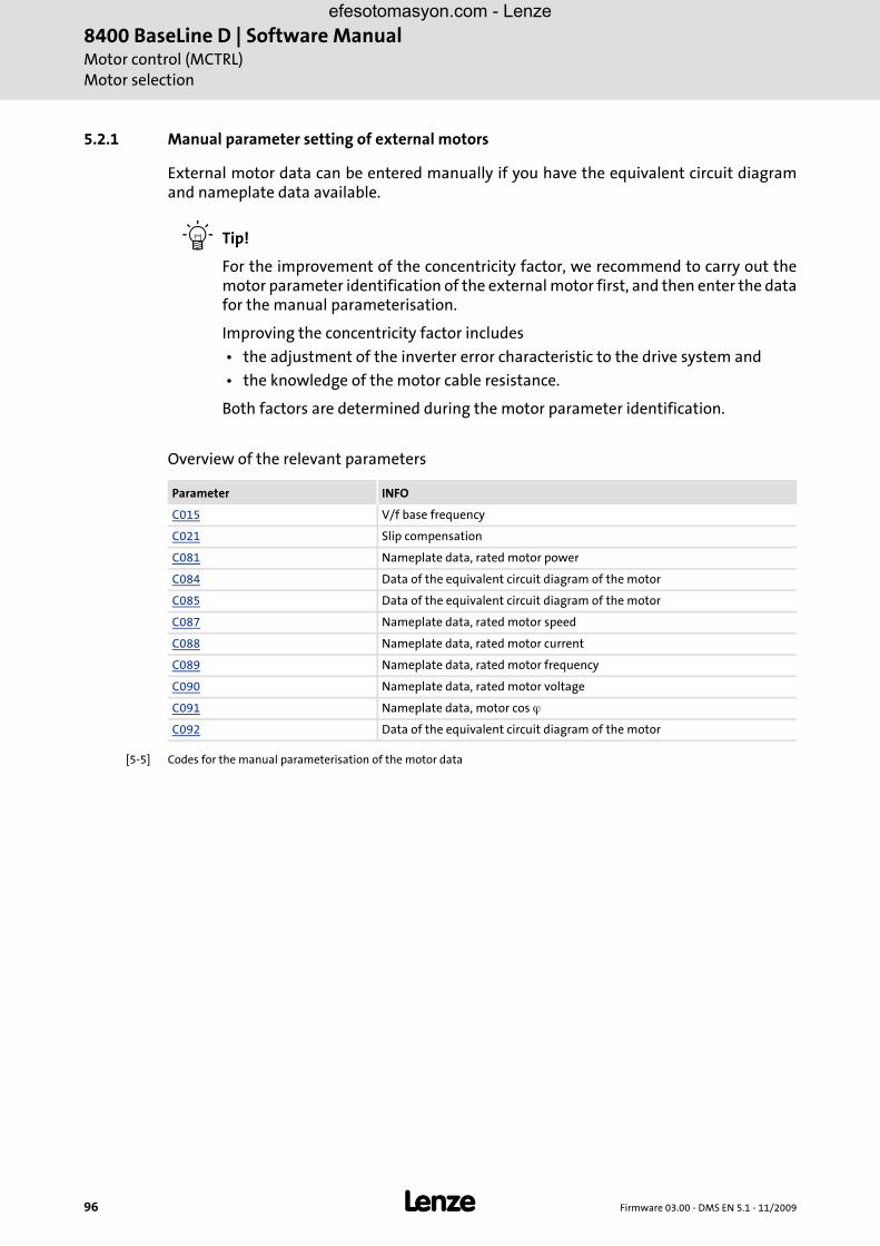
8400 BaseLine D | Software ManualMotor control (MCTRL)Motor selection
96 L Firmware 03.00 - DMS EN 5.1 - 11/2009
5.2.1 Manual parameter setting of external motors
External motor data can be entered manually if you have the equivalent circuit diagramand nameplate data available.
Tip!
For the improvement of the concentricity factor, we recommend to carry out themotor parameter identification of the external motor first, and then enter the datafor the manual parameterisation.
Improving the concentricity factor includes
• the adjustment of the inverter error characteristic to the drive system and
• the knowledge of the motor cable resistance.
Both factors are determined during the motor parameter identification.
Overview of the relevant parameters
[5-5] Codes for the manual parameterisation of the motor data
Parameter INFO
C015 V/f base frequency
C021 Slip compensation
C081 Nameplate data, rated motor power
C084 Data of the equivalent circuit diagram of the motor
C085 Data of the equivalent circuit diagram of the motor
C087 Nameplate data, rated motor speed
C088 Nameplate data, rated motor current
C089 Nameplate data, rated motor frequency
C090 Nameplate data, rated motor voltage
C091 Nameplate data, motor cos ϕ
C092 Data of the equivalent circuit diagram of the motor
efesotomasyon.com - Lenze

Firmware 03.00 - DMS EN 5.1 - 11/2009 L 97
8400 BaseLine D | Software ManualMotor control (MCTRL)
Selection of the switching frequency
5.3 Selection of the switching frequency
The switching frequency of the inverter has an effect on the smooth running performanceand the noise generation in the motor connected, as well as on the power loss in thecontroller.
The lower the switching frequency, the
better the concentricity factor
lower the power loss
higher the noise generation.
Adjustable switching frequencies:
Lowering the switching frequency due to high heatsink temperatures
If the maximally permissible heatsink temperature was exceeded, the drive would beinhibited due to the "Overtemperature" error and the motor would coast without anytorque.
Therefore, the switching frequency in the Lenze setting is lowered to the next smaller valuewhen the heatsink temperature has increased to 5 ° C below the maximum permissibletemperature.
After the heatsink has cooled down, the controller automatically switches to the nexthigher switching frequency up to the switching frequency set.
Lowering the switching frequency can be prevented using code C144. When the maximumpermissible heatsink temperature is reached, "Fault" is set for the respective switchingfrequency and the motor coasts, see code C165.
Note!
Operate the mid-frequency motors exclusively with the switching frequency f = 8 kHzsin or f = 16 kHzsin .
Parameter Values
C018 1: 4 kHz var./drive-optimised
2: 8 kHz var./drive-optimised
3: 16 kHz var./drive-optimised
4: Reserved
5: 2 kHz constant/drive-optimised
6: 4 kHz constant/drive-optimised
7: 8 kHz constant/drive-optimised
8: 16 kHz constant/drive-optimised
efesotomasyon.com - Lenze

8400 BaseLine D | Software ManualMotor control (MCTRL)Selection of the switching frequency
98 L Firmware 03.00 - DMS EN 5.1 - 11/2009
Lowering of the switching frequency depending on the output current
"Variable" switching frequencies can be selected for the controller in C018, where thecontroller automatically lowers the switching frequency depending on the controlleroutput current. The changeover threshold is included in the rated data of the HardwareManual. (The Hardware Manual can be found on the CD supplied with the device.)
When a "fixed" switching frequency is selected, no switching frequency changeover takesplace. In case of fixed frequencies, the controller output current is limited to thepermissible value of the corresponding switching frequency. In case of larger loadimpulses, the overcurrent interruption may be activated, to which the controller respondswith "Fault", see code C165.
Tip!
The Lenze setting "8 kHzvar" ( C018, value "2") is the optimum value for standard applications.
Limiting the maximum output frequency
The maximum output frequency of the controller is not limited depending on theswitching frequency.
For this reason, adapt the maximum output frequency according to our recommendation:
Carry out further measures:
If required, deactivate the switching frequency changeover by the heatsink temperature C144.
If required, ensure that the changeover threshold of the controller output current to the next smaller switching frequency will not be exceeded. If required, select a fixed switching frequency using code C018.
Operation at an ambient temperature of 45°C
The controller is designed so that operation at an ambient temperature of 45° C withoutderating is permissible at a switching frequency of 4 kHz.
Note!
For operation with a switching frequency of 16 kHz,
• the controller output current must not exceed the current limit values given in the technical data. Reduce the output current using the codes C022, C023.
• the Ixt evaluation C064 is considered with the required derating to 0.67 Irated (Irated - rated device current) at switching frequencies of 2, 4 and 8 kHz.
At a switching frequency of 4 kHz, for instance, 125 Hz for the maximum output frequency should not be exceeded.
aximum output frequency 132------Switching frequenc≤
efesotomasyon.com - Lenze
Firmware 03.00 - DMS EN 5.1 - 11/2009 L 99
8400 BaseLine D | Software ManualMotor control (MCTRL)
Definition of current and speed limits
5.4 Definition of current and speed limits
5.4.1 Definition of speed limits
Limitation of the speed setpoint
The parameter setting of code C00011 means with a speed setpoint of 100 % the drivemust rotate with the given value of the code. The speed setpoint information is given inpercent and refers to the reference speed set in C00011. For the sake of the resolution to beachieved and the connected accuracy, the reference speed should be based on the speedrange required in the prevailing application. Lenze recommendation: Reference speed = 1500 ... 3000 rpm.
Irrespective of the operating mode, there are more limitation options:
Limitation of the max. positive or negative speed C909/1 or /2
Limitation of the max. positive or negative output field frequency C910/1 or /2
Note!
In the torque-controlled operation (bTorqueModeOn = TRUE), the limitation of the speed setpoint has no function! In this case, a permissible speed range can be defined via the speed limitation (nSpeedHighLimit and nSpeedLowLimit).
efesotomasyon.com - Lenze

8400 BaseLine D | Software ManualMotor control (MCTRL)Definition of current and speed limits
100 L Firmware 03.00 - DMS EN 5.1 - 11/2009
5.4.2 Definition of current limits
The 8400 controllers are provided in the various operating modes with functions whichdetermine the dynamic behaviour under load and counteract the exceedance of themaximum current in motor or generator mode.
The max. motor or generator current is limited with the codes C022 or C023.
The current limits must be selected depending on
the permissible maximum motor current
– Recommendation: Imax < 1.5 ... 2.0 I(mot)N
the permissible maximum inverter current
the required motor or generator torque for the application
How to adapt the peak current limitation:
SLVC:
• Reduce slip compensation with C021.
• Reduce nTorqueMotLim C728/1 and nTorqueGenLim C728/2.
Note!
Highly dynamic applications(e.g. low acceleration and deceleration ramp times or greatly fluctuating loads)
The overcurrent disconnection may respond (fault message OC1 or OC11) when the parameterisation of the maximum current in motor mode C022 approximately corresponds to the maximum permissible value of the respective inverter.
Remedy by
• Increase of the acceleration and deceleration ramp time,
• Reduction of the maximum current C022 / C023 in motor/generator mode
• Adaptation of the indirect peak current limitation which is implemented depending on the type of operation (for procedure see below)
• Reduction of the reset time of the current limitation controller with C074/1.
efesotomasyon.com - Lenze

Firmware 03.00 - DMS EN 5.1 - 11/2009 L 101
8400 BaseLine D | Software ManualMotor control (MCTRL)Flying restart function
5.5 Flying restart function
The flying restart function works with a simple asynchronous motor model which requiresthe knowledge of the stator resistance RS and the rated motor current. In order that theflying restart function works properly, we recommend to carry out a parameteridentification before using the function. Automatic motor parameter identification( 93)
The flying restart function works safely and reliably for drives with great centrifugalmasses.
Tip!
• When power-adapted standard asynchronous motors are used (rated motor power approximately corresponds to the rated inverter power), a motor parameter identification is not required.
• In connection with the flying restart function, we recommend to read the information given in this manual in the chapter
Automatic DC-injection braking (Auto-DCB) ( 105)
5.5.1 General information
This function serves to activate a mode which is used to "catch" a coasting motor duringoperation without speed feedback. This means that the synchronicity between controllerand motor must be adjusted to achieve a jerk-free transition to the rotating machines inthe instant of connection.
The frequency inverter detects the synchronicity by identifying the synchronous fieldfrequency.
Duration
The "catching" process is completed after approx. 1 ... 2 seconds.
Overview of the relevant parameters
Note!
• Do not use the flying restart function if several motors with different centrifugal masses are connected to a controller.
• After the controller is enabled, the motor can start for a short time or reverse when machines with low friction and low mass inertia are used.
Parameter INFO
C990 Activation of flying restart function
C991 Selection of the flying restart function
C992 Selection of the starting frequency
C994 Current injection for the flying restart process
efesotomasyon.com - Lenze

8400 BaseLine D | Software ManualMotor control (MCTRL)Flying restart function
102 L Firmware 03.00 - DMS EN 5.1 - 11/2009
How to parameterise the flying restart function:
1. Activate flying restart circuit in C990 through "ON".
• Every time the controller is enabled, a synchronisation to the rotating or standing drive is carried out.
When the Lenze setting is used, most applications do not require additional controller settings.
If additional settings are necessary, proceed as follows:
2. Define the search mode for the flying restart circuit in C991:
• we recommend Lenze default setting "5": Last output frequency
We recommend to set a flying restart current of 10 % ... 25 % of the rated motor current.
• During a flying restart process, a current is injected into the motor to identify the speed.
• Reducing the current causes a reduction of the motor torque during the flying restart process. A short-time starting action or reversing of the motor is prevented with low flying restart currents.
• An increase of the current improves the robustness of the flying restart function.
efesotomasyon.com - Lenze

Firmware 03.00 - DMS EN 5.1 - 11/2009 L 103
8400 BaseLine D | Software ManualMotor control (MCTRL)
DC-injection braking
5.6 DC-injection braking
DC-injection braking allows the drive to be quickly braked to a standstill without the needto use an external brake resistor.
The braking current can be defined with code C036.
The maximum braking torque to be generated by the DC braking current is approx. 20 ... 30 % of the rated motor torque. It is lower than that for braking in generator mode with an external brake resistor.
Automatic DC-injection braking (Auto-DCB) improves the starting performance of the motor during operation without speed feedback.
Overview of the relevant parameters
DC-injection braking can be carried out in two ways with different types of activation:
Manual DC-injection braking (DCB) ( 104)
Automatic DC-injection braking (Auto-DCB) ( 105)
Parameter INFO
C019 Auto-DCB: thresholdResponse threshold for activating the DC-injection braking
C036 DCB: CurrentEnter the current in [%]
C106 Auto-DCB: hold time
C107 DCB: hold time
C701/4 See explanations for function block LA_NCtrl
efesotomasyon.com - Lenze

8400 BaseLine D | Software ManualMotor control (MCTRL)DC-injection braking
104 L Firmware 03.00 - DMS EN 5.1 - 11/2009
5.6.1 Manual DC-injection braking (DCB)
The DC-injection braking can be activated manually by assigning a digital input (E1 ... E4)to the DCB function.
For HIGH-active inputs, DC-injection braking is active as long as the signal is at HIGH level.
When the hold time C107 (999.0 s = hold time has no time limit) has expired, the controllersets the pulse inhibit (CINH).
efesotomasyon.com - Lenze
Firmware 03.00 - DMS EN 5.1 - 11/2009 L 105
8400 BaseLine D | Software ManualMotor control (MCTRL)
DC-injection braking
5.6.2 Automatic DC-injection braking (Auto-DCB)
"Automatic DC-injection braking" (in the following called "Auto-DCB") can be used whenthe drive has to be deenergised at n ≈ 0.
Function
For understanding the "Auto-DCB" function, it is necessary to distinguish between threedifferent types of operation:
1. When the drive is enabled and the speed setpoint falls below the Auto-DCB threshold during operation, a braking current C036 is injected. When the Auto-DCB hold time C106 has expired, the motor is deenergised via the Auto-DCB function, i.e. the controller inhibit (CINH) is set.
2. At the moment of controller enable, the drive is at standstill (n = 0). If the enabled drive is to start up, the speed setpoint passed via the acceleration ramp must exceed the Auto-DCB threshold C019. Below this threshold, the motor will not be energised.
3. At the moment of controller enable, the motor (still) rotates with a speed above the Auto-DCB threshold and the drive is "caught".For more detailed information on the topic see
Flying restart function ( 101).
How to set the automatic DC-injection braking
1. Set the hold time in code C106 to t > 0.0 s
• Automatic DC-injection braking is active for the time set.
• A braking current is injected (code C036).
• When the hold time C106 has expired, the controller sets the pulse inhibit.
2. Set the response threshold with C019. This code can be used to set a dead band in the setpoint. If DC-injection braking is not to be active here, C106 must be set to the value "0.0".
Stop!
If the DC-injection braking operation is too long and the braking current or braking voltage is too high, the connected motor may overheat.
efesotomasyon.com - Lenze

8400 BaseLine D | Software ManualMotor control (MCTRL)DC-injection braking
106 L Firmware 03.00 - DMS EN 5.1 - 11/2009
Explanation of the automatic DC-injection braking function by means of two examples
Example 1
[5-3] Example 1: Signal characteristic for automatic DC-injection braking
Example 2
[5-4] Example 2: Signal characteristic for automatic DC-injection braking
:Speed setpoint :Actual speed value of the motor :Controller output current :Pulse inhibit :DC-injection braking is active
:The motor rotates with the selected speed. The resulting current depends on the load .
:The DC braking current set in C036 is injected.
:When the hold time C106 has expired, the pulse inhibit is set.
�
�
�
�
� �
C0106
C00036
C00019
�
^
:Speed setpoint :Actual speed value of the motor :Controller output current :Pulse inhibit :DC-injection braking is active
:The motor rotates with the selected speed. The resulting current depends on the load .
:The DC braking current set in C036 is injected.
:The actual speed value of the motor follows the speed setpoint. The resulting current depends on the load.
�
�
�
�
� �
C00036
C00019
�
efesotomasyon.com - Lenze
Firmware 03.00 - DMS EN 5.1 - 11/2009 L 107
8400 BaseLine D | Software ManualMotor control (MCTRL)
DC-injection braking
5.6.3 Oscillation damping
Undesirable effects in every process are mechanical oscillations which may have anadverse effect on the single system components and/or the production output.
Mechanical oscillations in the form of speed oscillations are suppressed by the oscillationdamping function.
Oscillation damping is successfully used with
unloaded motors (no-load oscillations)
motors with a different rated power than that of the controller, e.g. at operation with high switching frequency and the related power derating.
operation with higher-pole motors
operation with special motors
compensation of resonances in the drive
– Some asynchronous motors can show resonances at an output frequency of approx. 20 ... 40 Hz which cause current and speed variations and thus destabilise the running operation.
How to eliminate speed oscillations:
1. Approach the area where the speed oscillations occur.
2. Reduce the speed oscillations by changing C234 and C235 step by step.
3. These can be indicators for smooth running:
• Constant motor current characteristic
• Reduction of the mechanical oscillations in the bearing seat
efesotomasyon.com - Lenze

8400 BaseLine D
| Software M
anualM
otor control (M
CTRL)
Signal flow
108Firm
ware 03.00 - D
MS EN
5.1 - 11/2009L
5.7 Signal flow
[5-5] Signal flow - V/f characteristic control without feedback
PWM
fPWM:C00018
0
1
f :C00910max
f :C00015
V :C00016base
min
n :C00909max
n16VoltageAddn16Boost
n16PWMAngleOffset
nEffSpeedSetValue Vsoll
fMod
nMotorVoltage
C00006
nEffCurrentIqnStatorCurrentIs
nLimSpeedSetVal
I :C00022
I :C00023maxMot
maxGen
V :C00073/1pT :C00074/1N
Motor slip model
0
1
nSpeedAdd
bSetQSP
Hz
%
Hz
%
f :C00015
V :C00016base
min
V/f linear
V/f sqare
nMotorFreqActC00059
OutputSpeedCtrl
C00021
C00105
ModulatorSelection ofcharacteristic
Slip compensationI controllermax
Transformationof coordinates
Invertererrorcharacteristic
efesotomasyon.com - Lenze

LFirm
ware 03.00 - D
MS EN
5.1 - 11/2009109
8400 BaseLine D
| Software M
anualM
otor control (M
CTRL)
Signal flow
[5-6] Sensorless vector control (speed control)
PWM
nOutputSpeedCtrl
nSpeedHighLimitnSpeedLowLimit
nSpeedCtrlPAdaptbSpeedCtrlPAdapt
nSpeedCtrllAct
nTorqueAdd
n16PWMAngleOffsetn16VoltAdd
nMotorSpeedAct
nReactCurrentId
Modulator
n16MotorFreqAct
C00018
fMod
iqset
iq
idset
Imr
�U�U
fMod
nMotorVoltage
I :C00022max
VP:C00073/2TN:C00074/2
R - C00084
L - C00085
L - C00092
S
h
�
PWM
Modulator
C00018
n :C00909max
nEffSpeedSetValue
0
1
nSpeedAdd
bSetQSP
Hz
%
bLimSpeedCtrlOut
nLimMotTorquenLimGenTorque
0
1
nActualFluxx
0
1
bAutoGSBIsActive
NIAutoGSB
nEffCurrentIq
Hz
Vp: C00985
%
f :C00910maxT :C00074/2
N
A
Nm
T :C00074/2
N
T_Rotor
T :C00074/1
N
T :C00074/2
N
nMotorTorqueAct
C00021
nEffCurrentIq
VP:C00070/1TN:C00071/1
I :C00023max
A
Nm
0
1
bTorqueModeOn
nSpeedCtrllSetbSpeedCtrll
bTorqueModeOn
nInputTorqueControlA
Nm
bLimCurrentSetValue
T :C00074/2
NFlux model
(Calculation of slip)
Motor voltage model
Speedlimitation
Transformationof coordinates
Invertererrorcharacteristic
VsetVsetDirect-axis current controller
Speed controller
Torque control withspeed limitation
Magnetization
Torque controller
efesotomasyon.com - Lenze

8400 BaseLine D | Software ManualMotor control (MCTRL)System block "LS_MotorInterface"
110 L Firmware 03.00 - DMS EN 5.1 - 11/2009
5.8 System block "LS_MotorInterface"
efesotomasyon.com - Lenze

Firmware 03.00 - DMS EN 5.1 - 11/2009 L 111
8400 BaseLine D | Software ManualMotor control (MCTRL)
Monitoring functions
5.9 Monitoring functions
5.9.1 Motor temperature monitoring with I²xt
The 8400 frequency inverter is provided with a simple, sensorless monitoring for thermal
"I2xt" motor overload of self-ventilated standard motors.
C066 displays the motor utilisation meter I2xt, which shows whether the motor isoverloaded or not.
The permissible overload time of the motor is reached with an overload of C066 = 100 %,
the message "Thermal motor overload, I2xt" (OC6) is output and the response set in C606is initiated (default setting: "warning").
C120 serves to enter the overload threshold for I2xt motor monitoring
Stop!
The I2xt motor monitoring does not provide a full motor protection! Since the motor utilisation calculated in the thermal motor model gets lost after switching the mains, the following operating states cannot be determined correctly:
• Restarting (after mains switching) of a motor that is already very hot.
• Change of the cooling conditions (e.g. cooling air flow interrupted or too warm).
A full motor protection requires additional measures as e.g. the evaluation of temperature sensors that are located directly in the winding or the use of thermal contacts.
efesotomasyon.com - Lenze
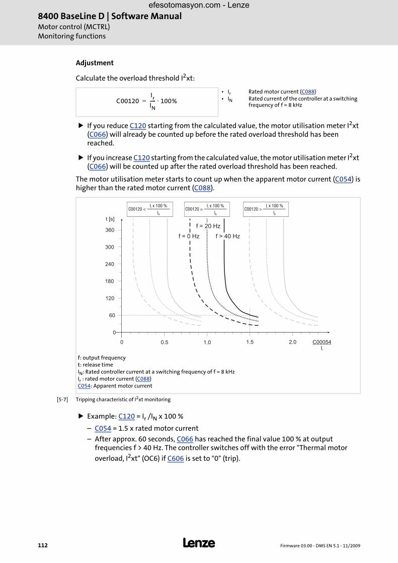
8400 BaseLine D | Software ManualMotor control (MCTRL)Monitoring functions
112 L Firmware 03.00 - DMS EN 5.1 - 11/2009
Adjustment
Calculate the overload threshold I2xt:
If you reduce C120 starting from the calculated value, the motor utilisation meter I2xt (C066) will already be counted up before the rated overload threshold has been reached.
If you increase C120 starting from the calculated value, the motor utilisation meter I2xt (C066) will be counted up after the rated overload threshold has been reached.
The motor utilisation meter starts to count up when the apparent motor current (C054) ishigher than the rated motor current (C088).
[5-7] Tripping characteristic of I2xt monitoring
Example: C120 = Ir /IN x 100 %
– C054 = 1.5 x rated motor current
– After approx. 60 seconds, C066 has reached the final value 100 % at output frequencies f > 40 Hz. The controller switches off with the error "Thermal motor
overload, I2xt" (OC6) if C606 is set to "0" (trip).
• Ir • IN
Rated motor current (C088)Rated current of the controller at a switching frequency of f = 8 kHz
f: output frequencyt: release timeIN: Rated controller current at a switching frequency of f = 8 kHzIr : rated motor current (C088)C054: Apparent motor current
C00120Ir
IN----- 100%⋅=
60
180
240
300
360
t [s]
0.50
0
1.0 1.5 2.0 C00054Ir
120
f = 0 Hz
f = 20 Hz
f > 40 Hz
I x 100 %
Ir
N
C00120 <I x 100 %
Ir
N
C00120 =I x 100 %
Ir
N
C00120 >
efesotomasyon.com - Lenze

Firmware 03.00 - DMS EN 5.1 - 11/2009 L 113
8400 BaseLine D | Software ManualMotor control (MCTRL)
Monitoring functions
Tip!
• To prevent the overload threshold of motors with forced ventilation from being triggered too early, deactivate this function.
• The current limits C022 and C023 only have an indirect influence on the I2xt calculation. The settings of C022 and C023, however, serve to prevent the motor from being operated with maximum possible utilisation.
efesotomasyon.com - Lenze
8400 BaseLine D | Software ManualMotor control (MCTRL)Monitoring functions
114 L Firmware 03.00 - DMS EN 5.1 - 11/2009
efesotomasyon.com - Lenze

Firmware 03.00 - DMS EN 5.1 - 11/2009 L 115
8400 BaseLine D | Software ManualI/O terminals
6 I/O terminals
This chapter informs about the function and the possible parameter settings of thecontroller's input and output terminals.
The parameters are set in the »Engineer« on the Terminal assignment tab. Here, "analogterminals" and "digital terminals" are distinguished in the Control connections list field:
Analog input ( 116)
Digital inputs ( 120)Digital outputs ( 122)
efesotomasyon.com - Lenze

8400 BaseLine D | Software ManualI/O terminalsAnalog input
116 L Firmware 03.00 - DMS EN 5.1 - 11/2009
6.1 Analog input
The controller has an analog input which serves to detect voltage signals as e.g. an analogspeed setpoint selection or the signal of an external sensor (temperature, pressure, etc.).
The following areas can be parameterised:
0 ... 10 V, C034/1 = 0
0 ... + 5 V, C034/1 = 1, with external load resistor (250 Ω): 0 ... 20 mA
+ 1 ... + 5 V C034/1 = 2, with external load resistor (250 Ω): 4 ... 20 mA
Moreover, current signals in the 0/+4 ... +20 mA range, ("Life Zero" including open-circuitmonitoring) can be detected via a load resistor (250 Ω) connected to the terminals.
Further possible parameter settings of the input signals of
– offset and
– gain
Diagnostics options:
– The monitored input can be queried with a status signal.
– Input and output values of the system block are displayed in the »Engineer« / internal keypad.
Note!
To prevent undefined states, free input terminals of the controller must be assigned as well, e.g. by applying 0 V (GND) to the terminal "X4/A1U".
efesotomasyon.com - Lenze

Firmware 03.00 - DMS EN 5.1 - 11/2009 L 117
8400 BaseLine D | Software ManualI/O terminalsAnalog input
6.1.1 Terminal assignment/electrical data
Terminal Use Electrical data
X4/A1U Voltage input / Current input
Level: • 0 ... + 10 V DC • 0 ... + 5 V DC (0 ... + 20 mA)*)
• 1 ... + 5 V DC (+ 4 ... + 20 mA)*)
Load resistor*): RB = 250 Ω According to the above graphics, a load resistor must be connected to current signals 0/+4 ... 20 mA.
Resolution: 10 Bit (Error: 1 digit ≡ 0.1 %, related to the actual value)
Scaling: When C034 = "0":± 10 V ≡ ± 214 ≡ 16384 ≡ ±100 %
Conversion rate: 1 kHzIn order to filter out short-term interferences from the analog signal characteristic, the analog input value is filtered with a digital lag filter with a time constant equal to 5 ms.
Input resistance > 80 kΩ for VDC250 Ω for mADC
Input voltage in caseof open circuit
Display 0 (U < 0.05 V, absolute)
Sampling frequency(processing cycle)
1 kHz (1 ms)
Accuracy ± 0.1 V
Electric strength ofexternal voltage
± 15 V, permanent
X4/GND GND, reference potential of analog signals
X4 GND
A1U
AR
12I
RFR
DI1
DI2
DI3
DI4
24E
DO1
RB
efesotomasyon.com - Lenze

8400 BaseLine D | Software ManualI/O terminalsAnalog input
118 L Firmware 03.00 - DMS EN 5.1 - 11/2009
6.1.2 Parameter setting
Short overview of the parameters for the analog input:
6.1.3 Using the analog input as current input
The current source must be connected to the X4/GND and X4/A1U plug connector.
Code C034, selection "1" and "2", serves to reconfigure the analog input 1 to a current input if a load resistor of 250 Ω is connected externally in parallel.
Tip!
The selection "2" serves to implement a 4 ...20 mA current loop, e.g. for fault-resistant speed setpoint selection.
Open-circuit monitoring
Use C598/1 to set an open circuit error response for the 4 ...20 mA current loop. This errorresponse is already activated in the Lenze setting!
Parameter INFO
C010/1 Minimum analog setpointMinimum and maximum output speed ( 119)
C011 Maximum output speed (reference speed)Minimum and maximum output speed ( 119)
C034 Configuration of analog input 1, evaluation of current (with external load resistor) or voltage
C598/1 Resp. to open circuit AIN1
C026/1 Analog input 1: Offset
C027/1 Analog input 1: Gain
C028/1 Analog input 1: Voltage input signal
C029/1 Analog input 1: Current input signal
C033/1 Analog input 1: AIN1_nIn_a
Highlighted in grey = display parameter
efesotomasyon.com - Lenze

Firmware 03.00 - DMS EN 5.1 - 11/2009 L 119
8400 BaseLine D | Software ManualI/O terminalsAnalog input
Minimum and maximum output speed
The speed range required for the application is set via the selection of the output speeds:
The maximum output speed which can be parameterised in code C011 is reached with a speed setpoint selection of 100 %. This value depends on the setpoint source and is considered as the reference speed for all other settings.
The value which can be parameterised in code C010 corresponds to the minimum speed if
– the input of the LS_AnalogInput block is connected to the X4/A1U input terminal (Lenze setting) and
– a voltage of 0 V applies to the X4/A1U input terminal.
[6-1] Relation between setpoint and minimum and maximum output speed
6.1.4 System block "LS_AnalogInput"
The system block LS_AnalogInput displays the analog input in the function block editor.
0 V
n
10 V
C011
C010
100 %
OutputData type
Value/meaning
nIn_aC033/1 | INT
Analog input 1 • Scaling:
± 214 ≡ ± 10 V for use as voltage input+ 214 ≡ + 20 mA (+ 5 V) for use as current input (with external load resistor)
bCurrentErrorIn1BOOL
Status signal "Current input error" • Only when analog input 1 is used as current input (with external load resistor). • Application: Cable-breakage monitoring of the 4 ...20 mA circuit.
True |IAIN1| < 4 mA
LS_AnalogInput
nIn_a
bCurrentErrorIn1
0
1
2
C027/1
D
C033/1C028/1
C026/1
C034/1
A
X4
GND
A1U
AR
efesotomasyon.com - Lenze

8400 BaseLine D | Software ManualI/O terminalsDigital inputs
120 L Firmware 03.00 - DMS EN 5.1 - 11/2009
6.2 Digital inputs
The four terminals DI1 ... DI4 of the plug connector X4 serve to detect digital signals.
Control input RFR serves to enable the controller and is firmly connected to the devicecontrol.
6.2.1 Terminal assignment/electrical data
6.2.2 Parameter setting
Short overview of parameters for the digital inputs:
Terminal Use Electrical data
X4/DI1..X4/DI4
Digital input 1 ... 4 LOW level: 0 ... 2.5 VDC
HIGH level: + 10 V ... + 30 V DC
Input current: 4 mA per input at 12 V DC(X4 / 12I)
Electric strength ofexternal voltage:
Max. ± 30 V, permanent
Input impedance: 3.3 kΩ
Processing cycle: 1 ms
X4/RFR Controller enable See digital inputs
X4/GND Reference potential (digital ground)
X4
24E
DO1
GND
A1U
AR
12I
RFR
DI1
DI2
DI3
DI4
Parameter INFO
C011 Reference speed of the drive
C114 Inversion of the digital input
C701 Linking of the digital inputs with different functions of the drive application is possible.
C443/1 Status: Terminal level • DI1 ... DI4: Bit 0 ... 3 • CINH: Bit 15
C443/2 Status: Output level • DI1 ... DI4: Bit 0 ... 3 • CINH: Bit 15
Highlighted in grey = display parameter
efesotomasyon.com - Lenze
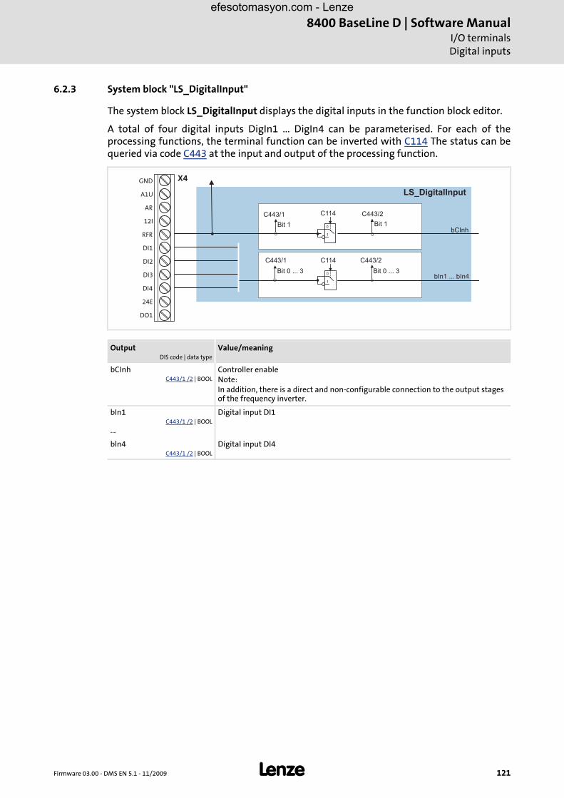
Firmware 03.00 - DMS EN 5.1 - 11/2009 L 121
8400 BaseLine D | Software ManualI/O terminalsDigital inputs
6.2.3 System block "LS_DigitalInput"
The system block LS_DigitalInput displays the digital inputs in the function block editor.
A total of four digital inputs DigIn1 ... DigIn4 can be parameterised. For each of theprocessing functions, the terminal function can be inverted with C114 The status can bequeried via code C443 at the input and output of the processing function.
OutputDIS code | data type
Value/meaning
bCInh C443/1 /2 | BOOL
Controller enableNote:In addition, there is a direct and non-configurable connection to the output stages of the frequency inverter.
bIn1C443/1 /2 | BOOL
...
Digital input DI1
bln4C443/1 /2 | BOOL
Digital input DI4
LS_DigitalInput
GND
A1U
AR
12I
RFR
DI1
DI2
DI3
DI4
24E
DO1
X4
bCInh
bIn1 ... bIn4Bit 0 ... 3
Bit 1
Bit 0 ... 3
Bit 1
C443/2C114
0
1
C443/1
C443/1 C443/2C114
0
1
efesotomasyon.com - Lenze

8400 BaseLine D | Software ManualI/O terminalsDigital outputs
122 L Firmware 03.00 - DMS EN 5.1 - 11/2009
6.3 Digital outputs
The controller is provided with a parameterisable digital output and a relay output.
6.3.1 Terminal assignment/electrical data
Note!
Initialisation behaviour:
• After mains switching up to the start of the application, the digital output remains set to FALSE.
Exception handling:
• In case of a critical exception in the application (e.g. reset), the digital output is set to FALSE considering the functional direction parameterised in C118.
Switching cycle diagnostics:
• Code C177/2 serves to evaluate the load of the relay by querying the switching cycles.
Terminal Use Electrical data
X4/DO1 Digital output 1 LOW level: 0 V
HIGH level: +12 ... +30 V (independent of the voltage at X4/24E)
Output current: max. 50 mA (external resistance > 480 Ω at 24 V)
Processing cycle: 1 ms
X4/24E External voltage (24 V DC) to supply the digital output
X4/GND Reference potential (digital ground)
X101/COM Relay output, common contact Potential-free two-way switchAC 250 V / 3 ADC 24 V / 2 A ... 240 V / 0.16 A (with suppressor circuit)Important: The minimum load must not fall below 12 V and 5 mA.
X101/NO Relay output, NC contact
X4
24E
DO1
GND
A1U
AR
12I
RFR
DI1
DI2
DI3
DI4 X101 NO
COM
efesotomasyon.com - Lenze

Firmware 03.00 - DMS EN 5.1 - 11/2009 L 123
8400 BaseLine D | Software ManualI/O terminals
Digital outputs
6.3.2 Parameter setting
Short overview of parameters for the digital outputs:
6.3.3 Function block "LS_DigitalOutput"
In the FB editor, the function block LS_DigitalOutput is the interface to the digital outputat the front of the controller.
Parameter Info
C118 Inversion of the output logic
C621/1 Linking the bRelay signal with the drive applicationLenze setting: LA_nCtrl_bDriveFail (50)
C621/2 Linking the bOut1 signal with the drive applicationLenze setting: LA_nCtrl_bDriveReady (51)
C177/2 Status: Switching cycles, output relay
C444/1 Status: Input level • Bit 0: bRelay • Bit 1: bOut1
C444/2 Status: Terminal level • Bit 0: bRelay • Bit 1: bOut1
Highlighted in grey = display parameter
InputDIS code | data type
Information/possible settings
bOut1C444/1 | BOOL
Digital output 1
bRelayC444/1 | BOOL
Relay output, potential-free make contact
LS_DigitalOutput
bOut1
X101bRelay
C118
0
1
C444/1 C444/2
Bit 0
Bit 1 Bit 1
Bit 0
C444/2C118
0
1
NO
COM
DI3
DI4
24E
DO1
X4
C444/1
efesotomasyon.com - Lenze

8400 BaseLine D | Software ManualI/O terminalsDigital outputs
124 L Firmware 03.00 - DMS EN 5.1 - 11/2009
efesotomasyon.com - Lenze

Firmware 03.00 - DMS EN 5.1 - 11/2009 L 125
8400 BaseLine D | Software ManualError management
Basics on error handling in the controller
7 Error management
7.1 Basics on error handling in the controller
In the controller many functions are integrated which detect errors and thus
protect the device against damage or overload, e.g. short circuit detection, Ixt overload detection, overtemperature detection, etc.
detect a maloperation by the user, e.g. memory module missing.
output a warning signal if desired, e.g. if the speed is too high or too low, etc.
Depending on the importance, this error detection in the device responds very fast (e.g.short circuit detection < 1 ms) or in a slower cycle (e.g. temperature monitoring approx.100 ms).
Furthermore, depending on their importance, some device errors can be configured withrespect to their effect on the behaviour of the controller (e.g. for user errors which mayoccur):
All functions provided with an error detection (e.g. the motor control) supply informationto an error handler which is processed every 1 ms and which evaluates all the information.
During this evaluation
the current error is generated
the controller is set to the respective error status (e.g. "fault").
These error data serve to diagnose errors systematically and contain the followinginformation:
1. the error type, e.g. warning
2. the subject area
3. the error identification number within the subject area
Together all types of information form the real error number which is unique in the wholedevice system.
In addition to the control of the device state by the error handler, a logbook functionrecords the errors and their history. Logbook ( 129)
7.2 Drive diagnostics with the »Engineer«
Tip!
The drive diagnostics with the integrated keypad is described in chapter
efesotomasyon.com - Lenze

8400 BaseLine D | Software ManualError managementDrive diagnostics with the »Engineer«
126 L Firmware 03.00 - DMS EN 5.1 - 11/2009
Diagnostics ( 25) beschrieben..
With an online connection to the controller, you can use the »Engineer« to carry out adiagnostics for the connected controller and get a clear visualisation of importantcontroller states:
The online connection to the »Engineer« can be made via the diagnostic interface X6.
[7-1] "Diagnostics" tab, screenshot for online connection to the frequency inverter
Use the Reset error button to acknowledge an existing error message if the cause of the error has been eliminated.
Use the Logbook button to display the logbook of the controller. For detailed information about the logbook, please see the chapter "Logbook" ( 129) .
The Device state button serves to display the state machine. The current device status is indicated by a field highlighted in blue.
The "Monitoring" button serves to set the monitoring functions (configuration of the error type).
If you click the Drive control button, a table appears providing information on the bit assignment of the following control-relevant words:
– Cause of controller inhibit C158
– Cause of quick stop C159
– Status word C150
– Extended status word C155
efesotomasyon.com - Lenze

Firmware 03.00 - DMS EN 5.1 - 11/2009 L 127
8400 BaseLine D | Software ManualError management
Drive diagnostics with the »Engineer«
Display parameters
The parameters listed in the following tables serve to query current states and actualvalues of the controller for diagnostic purposes, e.g. by using the internal keypad, a bussystem or the »Engineer« (with an online connection to the controller).
These parameters are listed in the »Engineer« parameter list and the internal keypad.
A detailed description of these parameters can be found in chapter "Parameter reference" ( 175).
Identification data
The parameters listed in the following table which are entered in the »Engineer«parameter list and in the internal keypad in the Identification Controller category, serveto display the identification data of the controller:
How to diagnose a drive with the »Engineer«:
1. Select the 8400 BaseLine controller to be diagnosed in the Project view.
2. Click the icon or select the command OnlineGo online to build up an online connection with the controller.
3. Select the Diagnostics tab.
• With an online connection, the Diagnostics tab displays current status information about the controller.
Parameter Display
C051 Actual speed value
C052 Motor voltage
C054 Motor current
C057 Maximum torque
C059 Appl. Nominal frequency C11
C061 Heatsink temperature
C064 Device utilisation (I x t)
C066 Thermal motor load (I2xt)
C168 Status-determining error
C178 Elapsed-hour meter
C179 Power-on time meter
Parameter Display
C093 Power section ID
C099, C100
Firmware version
C200 Firmware product type
C201 Firmware compile date
efesotomasyon.com - Lenze

8400 BaseLine D | Software ManualError managementDrive diagnostics with the »Engineer«
128 L Firmware 03.00 - DMS EN 5.1 - 11/2009
[7-2] Device state
[7-3] Drive control
efesotomasyon.com - Lenze

Firmware 03.00 - DMS EN 5.1 - 11/2009 L 129
8400 BaseLine D | Software ManualError management
Logbook
7.3 Logbook
The integrated logbook function of the controller chronologically logs important eventswithin the system and plays an important role for troubleshooting and controllerdiagnostics.
Events that can be logged
The following events can be logged in the logbook:
Error messages generated by the application
Information saved
For each event, the following information is saved in the logbook:
Type of response (e.g. fault, warning ) to the event
Subject area that activated the event (e. g. user).
Event
Value of power-on time meter
Memory depth
Maximum number of logbook entries: 8
efesotomasyon.com - Lenze

8400 BaseLine D | Software ManualError managementLogbook
130 L Firmware 03.00 - DMS EN 5.1 - 11/2009
7.3.1 Functional description
The structure of the logbook corresponds to a ring buffer:
[7-4] Ring buffer structure
In the event of a supply voltage failure, the logbook is saved and reloaded automaticallywhen the controller is switched on. This ensures that the error history of the device doesnot get lost. For this reason it is very important to act with caution when deleting thelogbook entries.
Current event
• As long as free logbook memory capacity is available, the entries will be saved at the next free memory location.
• If all memory locations are occupied, the oldest entry will be deleted to save a new entry.
nn-1
n-2
Note!
Events for which the response is set to "None" are not entered into the logbook.
efesotomasyon.com - Lenze

Firmware 03.00 - DMS EN 5.1 - 11/2009 L 131
8400 BaseLine D | Software ManualError management
Logbook
7.3.2 Reading out logbook entries
With an online connection, the existing logbook entries can simply be displayed in the»Engineer«. Alternatively, the logbook entries can also be read via the correspondingparameters (e.g. using the internal keypad).
How to display logbook entries in the »Engineer«:
1. Go to the Project view and select the 8400 BaseLine controller whose logbook entries are to be read.
2. Click the icon or select the command OnlineGo online to build up an online connection with the controller.
3. Select the Diagnostics tab from the Workspace.
4. Click Logbook.
• The Logbook dialog box appears
• Click Delete to delete an entry from the logbook.
• Click Export to export the entries from the logbook into a *.log file.
5. Click Previous to close the Logbook dialog box.
[7-5] Dialog area of the logbook
efesotomasyon.com - Lenze

8400 BaseLine D | Software ManualError managementMonitoring
132 L Firmware 03.00 - DMS EN 5.1 - 11/2009
7.4 Monitoring
The controller includes different monitoring functions that protect the drive againstimpermissible operating conditions.
If a monitoring function responds,
– an entry will be made into the Logbook of the controller,
– the response (troubleQSP, warning, fault, etc.) selected for the monitoring function will be activated,
– the status of the internal device control changes according to the selected response, controller inhibit is set, and the "DRIVE ERROR" LED on the front of the controller goes on:
Response Logbook entry
Display in C168
Pulse inhibit Controller inhibit
Acknowledgement required
LED "DRV-ERR"
None OFF
Fault
Trouble(after 0.5 s)
Warning locked
efesotomasyon.com - Lenze

Firmware 03.00 - DMS EN 5.1 - 11/2009 L 133
8400 BaseLine D | Software ManualError management
Monitoring
7.4.1 Setting the error response
When a monitoring function responds, the response set for this monitoring function(troubleQSP, warning, fault, etc.) will be activated.
For many monitoring functions the response can be individually parameterised via parameters.
Tip!
The table in chapter " Short overview (A-Z)" contains the error messages forwhich the response can be set ( 137) .
Warning thresholds
Some of the monitoring functions are activated if a defined warning threshold (e.g.temperature) has been exceeded.
The corresponding preset threshold values can be changed via the following parameters:
7.4.2 Monitoring of the device utilisation
In C064, the device utilisation (i x t) over the last 180 seconds is displayed in [%].
If the value displayed in C064 exceeds the warning threshold set in C123, the error message "Device utilisation Ixt > C123" is output and the error response set in C604 occurs (default setting: "Warning").
If the value displayed in C064 exceeds 100 %, the error message "device utilisation Ixt > 100 %" is output and the error response "fault" occurs.
– The error can only be reset if the value displayed in C064 is < 95 % again.
Parameter INFO
C120 Motor overload protection (I²xt)
C123 Device util. warning threshold
C174 Undervoltage (LU) threshold
efesotomasyon.com - Lenze

8400 BaseLine D | Software ManualError managementError messages of the operating system
134 L Firmware 03.00 - DMS EN 5.1 - 11/2009
7.5 Error messages of the operating system
This chapter describes all error messages of the controller operating system and possiblecauses & remedies.
Tip!
The error messages are also saved in the logbook in chronological order. Logbook( 129)
7.5.1 Error number
7.5.1.1 Structure of the error number (bit coding)
If an error occurs in the controller, the logbook saves a 32-bit value in the error formatwhich contains the following information:
[7-6] Structure of the error number
7.5.1.2 Error type
The error type is dynamically assigned by the operating system.
7.5.1.3 Error subject area
The subject area indicates the internal "function unit" of the controller in which the erroroccurred.
Reserved
Error type
Error subject area
Error ID
��� �
Bit 16252631 0152930
Bit 29 Bit 28 Bit 27 Bit 26 Meaning
0 0 0 0 0: No response
0 0 0 1 1: Pulse inhibit fault
0 0 1 0 2: Trouble
0 1 0 0 4: Warning locked
Bit 16252631 0152930
Bit 16252631 0152930
efesotomasyon.com - Lenze

Firmware 03.00 - DMS EN 5.1 - 11/2009 L 135
8400 BaseLine D | Software ManualError management
Error messages of the operating system
7.5.1.4 Error ID
16-bit value (0 ... 65535) for error identification.
7.5.1.5 Example for bit coding of the error number
C168 displays the error number "75169803".
This decimal value corresponds to the following bit sequence:
The bit-by-bit representation of the error number (divided into nibbles)0000⏐0100⏐0111⏐1011⏐0000⏐0000⏐0000⏐1011corresponds to the hexadecimal value of "0x47B000B"
The error number "75169803" thus means:In the "Motor management" subject area, an overcurrent has been detected. An "error pulse inhibit" occurred as a response to the error which has to be acknowledged after the error has been eliminated.
Bit 16252631 0152930
Assignment Information Meaning in the example
Reserved Assigned with 0b00
Error type 1: Pulse inhibit fault
Subject area 123: Motor management
Error ID 16: "Short circuit" (OC1)
Bit 16252631 0152930
0 0 0 0 0 1 0 0 0 1 1 1 1 0 1 1 0 0 0 0 0 0 0 0 0 0 0 0 1 0 1 1
0 0
0 0 0 1
0 0 0 1 1 1 1 0 1 1
0 0 0 0 0 0 0 0 0 0 0 0 1 0 1 1
efesotomasyon.com - Lenze

8400 BaseLine D | Software ManualError managementError messages of the operating system
136 L Firmware 03.00 - DMS EN 5.1 - 11/2009
7.5.2 Reset of error message
An error message with the response "Fault", "Trouble" or "Warning locked" must beexplicitly reset (acknowledged) after the cause of the error has been eliminated.
Error messages can be reset via
• the code C002/19 = "1"
• the »Engineer«
• the DCTRL input with C701/2 = "1" (terminal "X4/RFR": Low ---> High)
• Mains switching (switching off the mains and then on again)
Tip!
With an online connection to the controller, use the Diagnostics tab of the»Engineer« and click Error message reset to reset a pending error message.
efesotomasyon.com - Lenze

Firmware 03.00 - DMS EN 5.1 - 11/2009 L 137
8400 BaseLine D | Software ManualError management
Error messages of the operating system
7.5.3 Short overview (A-Z)
The following table contains all error messages of the controller operating system inalphabetical order with the preset error response and - if available – the parameter forsetting the error response.
Tip!
If you click the cross-reference in the last column "Detailed information", you getto the detailed description of the corresponding error message in the followingchapter "Cause & possible remedies" ( 138) .
[7-1] Monitoring
Error message Cross-reference / INFO
An01: AIN1_I < 4 mA An01
df01 ... df10: Internal error Please contact Lenze
dH69: Adjustment data error dH69
ID1: Motor data identification error ID1
LU: DC-bus undervoltage LU
OC1: Power section - short circuit OC1
OC2: Power section - earth fault OC2
OC5: Ixt overload OC5
OC6: I2xt motor overload OC6
OH: Heatsink overtemperature OH
OU: DC-bus overvoltage OU
PS01: No memory module PS01
PS02: Invalid parameter set PS02
PS03: Parameter set of device invalid PS03
PS04: Invalid parameter set PS04
PS31: Parameter set of different power class PS031
US01: User error 1 US01
US02: User error 2 US02
efesotomasyon.com - Lenze

8400 BaseLine D | Software ManualError managementError messages of the operating system
138 L Firmware 03.00 - DMS EN 5.1 - 11/2009
7.5.4 Cause & possible remedies
This chapter contains all error messages of the controller operating system in numericalorder of the error number with detailed information on the response to the error messageas well as information on the cause & possible remedies.
Tip!
A list of all error messages of the controller operating system in alphabetical ordercan be found in the previous chapter
Short overview (A-Z) ( 137).
Table of the individual errors
Subject area Error no. Error cause Error response
Remedy by the user
No. Name
119 Temperature 7798785 OH: Heatsink overtemperatureThe heatsink temperature is higher than the fixed limit temperature (90 ° C). The ambient temperature of the controller may be too high or the fan or its ventilation slots may be dirty.
1: Error - pulse inhibit ("Fault")
Check control cabinet temperature.Clean air filter of control cabinetClean controller.If required, clean or replace the fanProvide for sufficient cooling of the device.
119 Temperature 7798834 OC5: Ixt overloadThe Ixt overload check has tripped due to 1.) wrong dimensioning of the device with regard to its motor load or 2.) non-compliance with the load cycles
C00604 Regarding 1.) Check and, if required, correct the dimensioning between the device and motor load with regard to technical dataRegarding 2.) Reduce load cycles of the motor. Observe load cycles according to the documentation.
123 Motor management / encoder
8060942 OU: DC-bus overvoltageThe device has detected an overvoltage in the DC bus and an earth fault on the motor side. In order to protect the device hardware, the inverter control is switched off.Depending on the configuration of the auto-start lock function, C00142 serves to set that, if the this error has been tripped, the controller only starts after the controller inhibit is switched.If this error message remains active longer than the time set in C00601, a "Fault" is tripped.
2: Trouble Reduction of the load in generator mode.Use of a brake resistorUse of a regenerative power supply module.Layout of a DC-bus connection.Remove earth fault on the motor side.
123 Motor management / encoder
8060943 LU: DC-bus undervoltageThe device has detected an undervoltage in the DC bus. The inverter control is switched off since the drive characteristics of the motor control cannot be ensured anymore due to the DC-bus undervoltage. The configuration of the auto-start lock function C00142 serves to set that, after this error has tripped, the controller only starts after the controller inhibit is switched.
2: Trouble Switch on the mains supply or ensure sufficient supply via DC bus. Adapt C00142, if required
123 Motor management / encoder
8060944 OC1: Power section - short circuitThe device has detected a short circuit of the motor phases. In order to protect the device electronics, the inverter control is switched off. Mostly, faulty motor connections are the reason.If the device is dimensioned inappropriately with regard to the motor load and if the current limitation in the current controller is misadjusted (Imax controller), this error message may occur as well.See also the chapter Motor control - defining current limits
1: Error - pulse inhibit ("Fault")
Check of the motor connections and the corresponding plug connector at the device.Compliance with the permissible combinations of device and motor power.Do not set the dynamics of the current limitation controller too high.
efesotomasyon.com - Lenze

Firmware 03.00 - DMS EN 5.1 - 11/2009 L 139
8400 BaseLine D | Software ManualError management
Error messages of the operating system
123 Motor management / encoder
8060945 OC2: Power section - earth faultThe device has detected an earth fault of the motor phases. In order to protect the device electronics, the inverter control is switched off. Mostly, faulty motor connections are the reason.If the sinusoidal filters, motor cable lengths and cable types (capacity of shielding) are misdimensioned, discharge currents to PE may lead to this error message.
1: Error - pulse inhibit ("Fault")
Check of the motor connections and the corresponding plug connector at the device.Use of sinusoidal filters, cable lengths and cable types recommended by Lenze.
123 Motor management / encoder
8061033 OC6: I2xt motor overloadThermal overload of the motor
C00606 Check whether the motor overload threshold I²xt in code C120 is dimensioned correctly.Compliance with load requirements and, if required, correction of dimensioning. With control mode VFCplus:Check of the Vmin boost, see C00016For details see Setting Vmin boost
125 Analog I/O integrated
8192001 An01: AIN1 I < 4 mA C00598/1 Check wiring of the analog input terminal for open circuit.Check minimum current values of the signal sources.
144 Parameter set 9437185 PS01: No memory moduleMemory module is not plugged in.Either the memory module is not available or not correctly engaged in the slot.
5: Warning Plug in the memory module or make sure that it is engaged correctly.
144 Parameter set 9437186 PS02: Invalid parameter setParameter set filing invalid due to a previously incomplete saving of the parameter set (e.g. by voltage failure or pulling out the memory module during the saving process).
1: Error - pulse inhibit ("Fault")
Please make sure during the saving process that the voltage supply is kept up and the module remains plugged into the slot.
144 Parameter set 9437187 PS03: Parameter set of device invalidIncompatibility of the parameter set is e.g. caused if the parameter set in the memory module has a higher version than the basic device expects.
1: Error - pulse inhibit ("Fault")
When exchanging the memory modules, observe the downward compatibility.
144 Parameter set 9437188 PS04: Invalid parameter setA memory module incompatible for this device has been detected.
1: Error - pulse inhibit ("Fault")
If devices are exchanged, the parameter sets of the memory module for the device can be accepted by means of C002/c012 = "1".
144 Parameter set 9437215 PS31: Parameter set of different power classA parameter set of a memory module has been detected with a different power class and motor control SLVC (C006 = 4).
1: Error - pulse inhibit ("Fault")
Execute the motor parameter identification (C002/c023 = "1").
400 Device hardware defective
26214505 dH69: Adjustment data errorAdjustment data error - power section
1: Error - pulse inhibit ("Fault")
The device must be returned to Lenze.
980 US01: User error 1 64225281 US01: User error 1User error 1 of LS_SetError_1
C00581/1 Defined by the user
981 US02: User error 2 64290817 US02: User error 2User error 1 of LS_SetError_1
C00581/2 Defined by the user
Subject area Error no. Error cause Error response
Remedy by the user
No. Name
efesotomasyon.com - Lenze

8400 BaseLine D | Software ManualError managementError messages of the operating system
140 L Firmware 03.00 - DMS EN 5.1 - 11/2009
efesotomasyon.com - Lenze

Firmware 03.00 - DMS EN 5.1 - 11/2009 L 141
8400 BaseLine D | Software ManualDrive Application
8 Drive Application
The drive application is a drive solution provided with the experiences and know-how ofLenze in which function blocks interconnected to a signal flow form the basis forimplementing typical drive tasks.
Brief description of the drive application features
Configurable input signals for terminal or manual control
Free configuration of output signals
Offset and gain of the main setpoint
Up to 3 fixed setpoints for speed
Adjustable setpoint ramp times
Linear or S-shaped ramp
Manual jog (function depends on the device type)
Quick stop with adjustable ramp time
Motor potentiometer (can be switched on/off)
Load monitoring
This chapter describes the management and details of the drive application of the 8400BaseLine frequency inverter.
efesotomasyon.com - Lenze
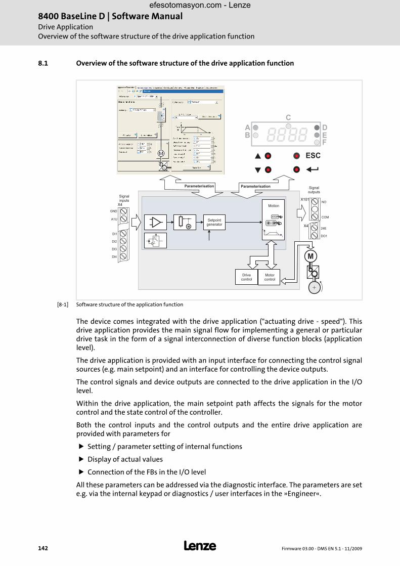
8400 BaseLine D | Software ManualDrive ApplicationOverview of the software structure of the drive application function
142 L Firmware 03.00 - DMS EN 5.1 - 11/2009
8.1 Overview of the software structure of the drive application function
[8-1] Software structure of the application function
The device comes integrated with the drive application ("actuating drive - speed"). Thisdrive application provides the main signal flow for implementing a general or particulardrive task in the form of a signal interconnection of diverse function blocks (applicationlevel).
The drive application is provided with an input interface for connecting the control signalsources (e.g. main setpoint) and an interface for controlling the device outputs.
The control signals and device outputs are connected to the drive application in the I/Olevel.
Within the drive application, the main setpoint path affects the signals for the motorcontrol and the state control of the controller.
Both the control inputs and the control outputs and the entire drive application areprovided with parameters for
Setting / parameter setting of internal functions
Display of actual values
Connection of the FBs in the I/O level
All these parameters can be addressed via the diagnostic interface. The parameters are sete.g. via the internal keypad or diagnostics / user interfaces in the »Engineer«.
STOP
M
M
0
1
n
t
��
8888B
ESC
C
DEF
A
X4
GND
A1U
DI1
DI2
DI3
DI4
X424E
DO1
X101NO
COM
Signalinputs
Motion
Drivecontrol
Motorcontrol
Signaloutputs
Setpointgenerator
ParameterisationParameterisation
efesotomasyon.com - Lenze

Firmware 03.00 - DMS EN 5.1 - 11/2009 L 143
8400 BaseLine D | Software ManualDrive Application
Overview of the software structure of the drive application function
8.1.1 Input and output interconnection of the drive application
The input and output interconnection, the individual control signals are shown which acton the drive application:
[8-2] Interconnection of the signal sources, marking: analog input 1 as main setpoint
MiscellaneousbUserLED
LS_DisFreewDis1
wDis2
wDis3
wDis4
LS_DisFree_bbDis1
.
.
bDis8
LS_AnalogInput
bCurrentErrorIn1
nIn1_a
LS_ParFree_b
bPar1
.
.
bPar16
LS_ParFixbTrue
nPos100_a
nNeg100_a
nPos199_9_a
nNeg199_9_a
w35535
wDriveCtrl
LS_Keypad
bSetQuickstop
bSetDCBrake
nTorqueMotLim
bSetSpeedCcw
nMainSetValue
bJogSpeed1
bJogSpeed2
LS_ParFree_anPar1_a
nPar2_a
nPar3_a
nPar4_a
LS_DisFree_anDis1_a
nDis2_a
nDis3_a
nDis4_a
LS_DigitalOutputbRelay
LS_DigitalInput
bCInh
bIn1
bIn2
bIn3
bIn4
bDriveReady
bSpeedCcw
bSpeedSetReached
bNActCompare
bImaxActive
bSpeedActEqSet
nOut_a
bUp
bDown
bInAct
nln_a
bEnable
bDown
bRfg0
nPIDVpAdapt_anPIDVpAdapt_a
bNSetInv
nNSet_a
L_PCTRL:nNOut_a
bNSetInv
bPIDInfluenceRampbPIDInfluenceRamp
bPIDIOffbPIDIOff
bSetDCBrake
bSetQuickstop
nNSet_a
nPIDSetValue_anPIDSetValue_a
nTorqueMotLim_a
bSetDCBrake
bRLQCw
bRLQCcw
bFailReset
bSetQuickstop
bCInh
bRFG_0
nTorqueGenLim_a
bJog2
nPIDInfluence_anPIDInfluence_a
bJogSpeed2bJog1
nPIDActValue_anPIDActValue_a
bJogSpeed1
bCInhActive
bDriveReady
wDeviceStateWordwDeviceAuxStateWord
wDetermFailNoLow
wDetermFailNoHigh
VFCplus
nNOut_a
nNOut_a
LS_DriveInterface
bFailReset
bSetError2bSetError2
bCInh
bMPOTDown
bMPOTUp
bMPOTEnable
bMPOTInAct
nMainSetValue_a
bSetSpeedCcw
bSetError1bSetError1
bStatus_Bit0bStatus_Bit0
bStatus_Bit2bStatus_Bit2
bStatus_Bit3bStatus_Bit3
bStatus_Bit4bStatus_Bit4
bStatus_Bit5bStatus_Bit5
bStatus_Bit14bStatus_Bit14
bStatus_Bit15bStatus_Bit15
wDetermFailNoLow
wDetermFailNoHigh
bDriveReady
wDeviceStateWord
wDeviceAuxStateWord
bDriveFail
bSafeTorqueOffbSafeTorqueOff
bSafetyIsActivebSafetyIsActive
bCInhActive
bSpeedActEqSet
L_NSet
L_PCTRL
L_MPot
nTorqueMotLim_a
nTorqueGenLim_a
bQSPIsActive
bNActCompare
bSpeedCcw
bImaxActive
bActSpeedEqZero
bSpeedActEqSet
bDriveFail
bHeatSinkWarningbHeatSinkWarning
bOVDetectedbOVDetected
bDCBrakeOnbDCBrakeOn
nMotorCurrent_anMotorCurrent_a
nOutputSpeedCtrl_anOutputSpeedCtrl_a
nMotorSpeedAct_anMotorSpeedAct_a
nMotorTorqueAct_anMotorTorqueAct_a
nDCVoltage_anDCVoltage_a
nHeatsinkTemperature_a
bFlyingSyncActive
nHeatsinkTemperature_a
bFlyingSyncActive
nMotorVoltage_a nMotorVoltage_a
nMotorFreqAct_a nMotorFreqAct_a
bSpeedCcw
bActSpeedEqZero
bQSPIsActive
bNActCompare
bSpeedSetReachedbSpeedSetReached
bImaxActive
RLQ
1
1
LA_NCtrl
wCANDriveControlwCANDriveControl
SpeedSetValue_a
VFCplus:SpeedSetValue_a
efesotomasyon.com - Lenze

8400 BaseLine D
| Software M
anualD
rive Application
Overview
of the softw
are structu
re of the drive application
fun
ction | Fu
nction
s of the drive application
144L
Firmw
are 03.00 - DM
S EN 5.1 - 11/2009
8.1.2 Functions of the drive application "Actuating drive - speed"
Function BaseLine D BaseLine C StateLine C HighLine C
Connection of device I/Os Adjustable via parameter tablesAdditionally configurable via parameters or FB Editor
Signal flow generation Predefined in the deviceSome functions can be switched on and off via parameters
Freely configurable via FB Editor
FB Editor, I/O level - Yes, editable
FB Editor, application level Diagnostics only Yes, editable
Open-loop operationClosed-loop operation
YesNo
YesNo
YesYes
YesYes
Speed setpoint selection via ramp function generator with S-shaped (jerk-free) ramp characteristic
Yes Yes Yes Yes
Number of fixed setpoints 3 3 15 15
Number of ramp times 1 1 15 15
Function for comparing the actual speed with the digital feedback
Yes Yes Yes Yes
Reversal of CW/CCW rotation via digital signal
Yes Yes Yes Yes
Set/reset error Yes Yes Yes Yes
Diagnostics of the digital and analog inputs and outputs
Yes Yes Yes Yes
Configurable connection of control and status signals
Yes Yes Yes Yes
Adjustable load monitoring Yes Yes No Yes
Integrated automatic brake operation Yes, simple speed threshold
Yes, simple speed threshold
Yes, simple speed threshold
Yes, with additional functions
Expandable by signal interconnection Only in the I/O level Only in the I/O level Only in the I/O level Yes
Blocking speeds Yes Yes Yes Yes
Motor potentiometer function Yes Yes Yes Yes
PID process controller Yes Yes Yes Yes
Manual jog No No Yes Yes, two speeds
Automatic load identification and control parameter setting
No No No No
efesotomasyon.com - Lenze
Firmw
are 03.00 - DM
S EN 5.1 - 11/2009
L145
8400 BaseLine D
| Software M
anualD
rive Application
Overview
of the softw
are structu
re of the drive application
fun
ction | Fu
nction
s of the drive application
Selection of the control type
The selection of the control type determines how the drive application of the BaseLine is to be controlled. The following types areavailable:
1. Terminal control (Lenze setting)
2. Control via internal keypad / PC
The device inputs and outputs called system blocks at Lenze are the interfaces between the (internal) drive application and theperipheral inputs and outputs of the controller. The terminals, for instance, are important inputs and outputs for the user. Thefrequency inverter has one analog input and several digital inputs and outputs.
The interconnections between system blocks and the drive application are assigned with code C007. An overview of the signalsaffecting the inputs and outputs of the drive application is provided by the table in chapter Pre-assignment of the drive application( 146). Die Tabelle gibt die Verknüpfungen in der Lenze-Einstellung wieder..
efesotomasyon.com - Lenze

8400 BaseLine D
| Software M
anualD
rive Application
Overview
of the softw
are structu
re of the drive application
fun
ction | Pre-assign
men
t of the drive
146L
Firmw
are 03.00 - DM
S EN 5.1 - 11/2009
8.1.3 Pre-assignment of the drive application
Input connections
Code InputLA_NCtrl:
Code C007, value:
10 (Terminal 0) 12 (Terminal 2) 14 (Terminal 11) 16 (Terminal 16) 20 (Keypad) 21 (PC)
C700/1 nMainSetValue_a LS_AnalogInput:nIn1_a (X4/A1U) LS_Keypad:nMainSetValue_a
LS_ParFree_a:nPar1_a
C700/2 nTorqueMotLm_a LS_ParFree_a:nPar3_a LS_Keypad:nTorqueMotLim_a
LS_ParFree_a:nPar3_a
C700/3 nTorqueGenLm_a LS_ParFree_a:nPar3_a LS_Keypad:nTorqueGenLim_a
LS_ParFree_a:nPar3_a
C700/6 nPIDVpAdapt_a LS_ParFix:nPos100_a
C700/8 nPIDInfluence_a LS_ParFix:nPos100_a
C701/2 bFailReset LS_DigitalInput:bCInh (X4/RFR)
C701/3 bSetQuickstop - LS_DigitalInput:bIn3(X4/DI3)
- - LS_Keypad:bSetQuickstop -
C701/4 bSetDCBrake LS_DigitalInput:bIn3 (X4/DI3)
- LS_DigitalInput:bIn2(X4/DI2)
- LS_Keypad:bSetDCBrake LS_ParFree_b:bPar3_a
C701/5 bSetSpeedCcw LS_DigitalInput:bIn4(X4/DI4)
LS_DigitalInput:bIn1(X4/DI1)
- LS_Keypad:bSetSpeedCcw LS_ParFree_b:bPar4_a
C701/6 bJogSpeed1 LS_DigitalInput:bIn1, (X4/DI1) - LS_DigitalInput:bIn1, (X4/DI1)
LS_Keypad:bJogSpeed1 LS_ParFree_b:bPar1_a
C701/7 bJogSpeed2 LS_DigitalInput:bIn2, (X4/DI2) - LS_DigitalInput:bIn2, (X4/DI2)
LS_Keypad:bJogSpeed2 LS_ParFree_b:bPar2_a
C701/8 bMPotUp - - LS_DigitalInput:bIn3(X4/DI3)
- - -
C701/9 bMPotDown - - LS_DigitalInput:bIn4(X4/DI4)
- - -
C701/11 bMPotEnable - - LS_ParFix:bTrue - - -
C701/12 bRFG_0 - - - - - -
C701/15 bPIDInfluenceRamp
LS_ParFix:bTrue
C701/17 bRLQCw LS_ParFix:bTrue LS_ParFix:bTrueLS_DigitalInput:bIn3 (X4/DI3)
LS_ParFix:bTrue
C701/18 bRLQCcw - LS_DigitalInput:bIn4 (X4/DI4)
-
efesotomasyon.com - Lenze

Firmw
are 03.00 - DM
S EN 5.1 - 11/2009
L147
8400 BaseLine D
| Software M
anualD
rive Application
Overview
of the softw
are structu
re of the drive application
fun
ction | Pre-assign
men
t of the drive
Output connections
Code Name Code C007, output LA_NCtrl, value:
10 (Terminal 0) 12 (Terminal 2) 14 (Terminal 11) 16 (Terminal 16) 20 (Keypad) 21 (PC)
C620/5 LS_DisFree:wDis1
- - - - LA_NCtrl:wDeviceStateWord
C620/9 LS_DisFree:nDis1_a
- - - - LA_NCtrl:nMotorSpeedAct_a
C620/10 LS_DisFree:nDis2_a
- - - - LA_NCtrl:nOutputSpeedCtrl_a
C620/20 LP_CAN-OUT1:wState
- - - - - -
C620/21 LP_CAN-OUT1:wOut2
- - - - - -
C620/22 LP_CAN-OUT1:wOut3
- - - - - -
C621/1 LS_DigitalOutput:bRelay (X101)
LA_NCtrl:bDriveFail
C621/2 LS_DigitalOutput:bOut1 (X4/DO1)
LA_NCtrl:bDriveReady
C621/6 USER-LED LA_NCtrl:bNActCompare
C621/8 LA_NCtrl:bStatusBit2
LA_NCtrl:bImaxActive
C621/9 LA_NCtrl:bStatusBit3
LA_NCtrl:bSpeedSetReached
C621/10 LA_NCtrl:bStatusBit4
LA_NCtrl:bSpeedActEqSet
C621/11 LA_NCtrl:bStatusBit5
LA_NCtrl:bNActCompare
C621/12 LA_NCtrl:bStatusBit14
LA_NCtrl:bSpeedCcw
C621/13 LA_NCtrl:bStatusBit15
LA_NCtrl:bDriveReady
C621/16 LS_DisFree:bDis1
- LA_NCtrl:bDriveReady
C621/17 LS_DisFree:bDis2
- LA_NCtrl:bDriveFail
efesotomasyon.com - Lenze

8400 BaseLine D | Software ManualDrive ApplicationInterface description of the drive application
148 L Firmware 03.00 - DMS EN 5.1 - 11/2009
8.2 Interface description of the drive application
[8-3] Drive application LA_NCtrl
nOut_a
bUp
bDown
bInAct
nln_a
bEnable
bDown
bRfg0
nPIDVpAdapt_anPIDVpAdapt_a
bNSetInv
nNSet_a
L_PCTRL:nNOut_a
bNSetInv
bPIDInfluenceRampbPIDInfluenceRamp
bPIDIOffbPIDIOff
bSetDCBrake
bSetQuickstop
nNSet_a
nPIDSetValue_anPIDSetValue_a
nTorqueMotLim_a
bSetDCBrake
bRLQCw
bRLQCcw
bFailReset
bSetQuickstop
bCInh
bRFG_0
nTorqueGenLim_a
bJog2
nPIDInfluence_anPIDInfluence_a
bJogSpeed2bJog1
nPIDActValue_anPIDActValue_a
bJogSpeed1
bCInhActive
bDriveReady
wDeviceStateWordwDeviceAuxStateWord
wDetermFailNoLow
wDetermFailNoHigh
VFCplus
nNOut_a
nNOut_a
LS_DriveInterface
bFailReset
bSetError2bSetError2
bCInh
bMPOTDown
bMPOTUp
bMPOTEnable
bMPOTInAct
nMainSetValue_a
bSetSpeedCcw
bSetError1bSetError1
bStatus_Bit0bStatus_Bit0
bStatus_Bit2bStatus_Bit2
bStatus_Bit3bStatus_Bit3
bStatus_Bit4bStatus_Bit4
bStatus_Bit5bStatus_Bit5
bStatus_Bit14bStatus_Bit14
bStatus_Bit15bStatus_Bit15
wDetermFailNoLow
wDetermFailNoHigh
bDriveReady
wDeviceStateWord
wDeviceAuxStateWord
bDriveFail
bSafeTorqueOffbSafeTorqueOff
bSafetyIsActivebSafetyIsActive
bCInhActive
bSpeedActEqSet
L_NSet
L_PCTRL
L_MPot
nTorqueMotLim_a
nTorqueGenLim_a
bQSPIsActive
bNActCompare
bSpeedCcw
bImaxActive
bActSpeedEqZero
bSpeedActEqSet
bDriveFail
bHeatSinkWarningbHeatSinkWarning
bOVDetectedbOVDetected
bDCBrakeOnbDCBrakeOn
nMotorCurrent_anMotorCurrent_a
nOutputSpeedCtrl_anOutputSpeedCtrl_a
nMotorSpeedAct_anMotorSpeedAct_a
nMotorTorqueAct_anMotorTorqueAct_a
nDCVoltage_anDCVoltage_a
nHeatsinkTemperature_a
bFlyingSyncActive
nHeatsinkTemperature_a
bFlyingSyncActive
nMotorVoltage_a nMotorVoltage_a
nMotorFreqAct_a nMotorFreqAct_a
bSpeedCcw
bActSpeedEqZero
bQSPIsActive
bNActCompare
bSpeedSetReachedbSpeedSetReached
bImaxActive
RLQ
1
1
LA_NCtrl
wCANDriveControlwCANDriveControl
SpeedSetValue_a
VFCplus:SpeedSetValue_a
efesotomasyon.com - Lenze

Firmware 03.00 - DMS EN 5.1 - 11/2009 L 149
8400 BaseLine D | Software ManualDrive Application
Interface description of the drive application
Inputs
Identifier/data type Information/possible settings
bSetQuickstopC701/3
BOOL
The quick stop function is activated via this control signal. TRUE = quick stop is active. Here, the drive ramps down the QSP ramp C0105 to speed = 0 and • keeps the motor at n = 0 if closed loop is active • sets pulse inhibit if Auto-DCB is activated
bRFG_0C701/12
BOOL
When bRFG_0 = TRUE, the setpoint generator leads its currently generated speed value to zero via the ramps parameterised.
nTorqueMotLim_aC700/2
INT
These input signals are directly transferred to the motor control to limit the controller's maximum torque in motor and generator mode.Negative values at these inputs are interpreted as "0" and have the following effects: • Internal limitation of the torque at 199.9% (upper limit) • The drive cannot supply a higher torque in motor mode than set herewith
100% = Mmax from C057
nTorqueGenLim_aC700/3
INT
These input signals are directly transferred to the motor control to limit the controller's maximum torque in motor and generator mode.Negative values at these inputs are interpreted as "0" and have the following effects: • Internal limitation of the torque 199.9% (lower limit) • The drive cannot supply a higher torque in generator mode than set herewith
100% = Mmax from C057
bSetDCBrakeC701/4
BOOL
The bSetDCBrake control signal brakes the drive to standstill. TRUE = SetDCBrake is active. • Braking current (C036) and hold time (C106 / C107) are adjustable • Braking process: DC-injection braking. Advantage of the DC-injection braking:The DC-injection braking provides the opportunity to influence the braking time by changing the motor current or braking torque.The braking effect stops when the rotor is at standstill.
bSetSpeedCcwC701/5
BOOL
This control signal serves to change over the direction of rotation of the drive to CCW rotation.When the signal is TRUE and the main setpoint is positive, the motor shaft rotates CCW
nMainSetValue_aC700/1
INT
Main setpoint
bJogSpeed1C701/6bJogSpeed2C701/7
BOOL
---> Fixed speedsThese control inputs serve to select fixed setpoints.The JOG setpoints are set relatively in percent [%] of the reference speed C011. The digital control signals bJogSpeed1 and JogSpeed2 serve to switch off the main setpoint and activate the JOG setpoint at the same time. A total of 3 JOG setpoints can be selected.The coding for the enabling of the JOG values is carried out according to the following table: • Main setpoint:
bJogSpeed1 = 0, bJogSpeed2 =0 • JOG 1 (C039/1):
bJogSpeed1 = 1, bJogSpeed2 =0 • JOG 2 (C039/2):
bJogSpeed1 = 0, bJogSpeed2 =1 • JOG 3 (C039/3):
bJogSpeed1 = 1, bJogSpeed2 =1
Acceleration and deceleration times for the main setpoint pathThe main setpoint is led via a ramp function generator. This serves to convert input steps into a ramp.The acceleration and deceleration times refer to a change of the speed from 0 to nmax (0% to 100%). The calculation of the Tir (C012) and Tif (C013) times to be set is described in the NSET function block description.
efesotomasyon.com - Lenze

8400 BaseLine D | Software ManualDrive ApplicationInterface description of the drive application
150 L Firmware 03.00 - DMS EN 5.1 - 11/2009
bMPOTUpC701/8bMPOTDownC701/9bMPOTInActC701/10bMPOTEnableC701/11
BOOL
---> Motor potentiometer functionThe application is provided with an integrated motor potentiometer. This function can be switched on/off via the parameters C701/11 or C806 = 1.When the function is switched on, the motor potentiometer is connected to the main setpoint path and thus acts as signal source for the main speed setpoint.This setpoint can be ramped up and down by means of the digital control inputs bMPOTUp and bMPOTDown via a parameterisable ramp time (C802, C803).
bCInhC701/1
BOOL
There are several options to inhibit the controller: • Terminal 28 (RFG)
This signal acts fail-safe and always inhibits the controller. FALSE : controller inhibit is active
• Control parameter C2/16.0: controller inhibit is active
• bCinh at the control input of the applicationTRUE: controller inhibit is active
As long as one of these controller inhibit sources is set, the drive remains in the controller inhibited status. The reason for the "controller is inhibited" status can be detected via the C0158 parameter.When controller inhibit is set, the drive loses its torque, the machine is coasting. When the controller inhibit request is reset, the drive synchronises to the actual speed. For this purpose, • an automatic flying restart function of the device is activated, if required (see
parameter C990) • the actual speed from the motor model of the motor control is used for
synchronisation for vector control without feedback.
bFailResetC701/2
BOOL
C701/2A pending error can be reset by a LOW-HIGH edge (Lenze setting, linkage with terminal X4/RFR) of this digital control signal if the cause of the fault has been eliminated.If the fault still exists, the error status remains unchanged.
bSetError1C701/13bSetError2C701/14
BOOL
bStatus_Bit0C621/7bStatus_Bit2C621/8..bStatus_Bit5C621/11
bStatus_Bit14C621/12bStatus_Bit15C621/13
BOOL
Identifier/data type Information/possible settings
efesotomasyon.com - Lenze

Firmware 03.00 - DMS EN 5.1 - 11/2009 L 151
8400 BaseLine D | Software ManualDrive Application
Interface description of the drive application
Outputs
Identifier/data type Information/possible settings
wDriveControlStatusWORD
For detailed description see Status word output ( 65)Application control via a bus system is possible with the 8400 BaseLine C controller.
wCurrentFailNumberWORD
Shows the current error numbers.For a detailed description of the structure of error numbers see
Error number ( 134) .
bDriveReadyWORD
Display: Drive is ready to process setpoints. No error occurred.
bDriveFailBOOL
An error occurred. The error type is as follows: • Fault • Trouble • WarningLocked
bCInhActiveWORD
Display: Controller inhibit is activated
bQSPIsActiveWORD
Display: Quick stop is activated
bSpeedCcwWORD
Display: Direction of motor rotation with respect to actual speed value.TRUE: Motor rotates anti-clockwise (as viewed looking onto the motor shaft)
bSpeedActCompareWORD
TRUE: The actual speed value is lower than the value set in C024.
bImaxActiveWORD
TRUE: The controller operates at the maximum current limit
bSpeedSetReached, bSpeedActEqSet
WORD
• bSpeedSetReachedTRUE: Speed setpoint reached.
• bSpeedSetReachedTRUE: Actual speed value has reached setpoint within one hysteresis band
nMotorCurrent_aWORD
Output of the current motor current
nMotorSpeedSet_a, nMotorSpeedAct_a
WORD
• nMotorSpeedSet_a:resulting total speed setpoint.
• nMotorSpeedAct_a:actual speed value
nMotorTorqueAct_aWORD
Current actual torque value
nDCVoltage_aWORD
Actual DC-bus voltage
nMotorVoltage_aWORD
Currently applied motor voltage
efesotomasyon.com - Lenze

8400 BaseLine D | Software ManualDrive ApplicationInterface description of the drive application
152 L Firmware 03.00 - DMS EN 5.1 - 11/2009
efesotomasyon.com - Lenze

Firmware 03.00 - DMS EN 5.1 - 11/2009 L 153
8400 BaseLine D | Software ManualFunction libraryFunction blocks
9 Function library
9.1 Function blocks
9.1.1 L_NSet
This FB is used for general signal processing of process values and is provided with thefollowing functions:
Ramp function generator with linear ramps for main setpoint path
Setting and holding the ramp function generator
S-shaped ramp (PT1 rounding) of the ramp function generator
Internal limitation of the input signal
3 fixed setpoints (JOG setpoints)
Inputs
Outputs
Identifier/data type Information/possible settings
bRfg0C701/12
BOOL
Leading the main setpoint integrator to 0 within the current Ti times
True The current value of the mains setpoint integrator is led to "0" via the Ti time set.
bNSetInvC701/5
BOOL
Signal inversion for the main setpoint
True Main setpoint signal is inverted.
nNSet_aC039/12
INT
Main setpoint signal • Other signals are also permitted
bJog1 ... bJog2C701/6 ... C701/7
BOOL
Selection inputs for fixed change-over setpoints (JOG setpoints) for the main setpoint • Selection inputs are binary coded.
Identifier/data type Value/meaning
nNOut_aINT
Speed setpoint output signal • 16384 ≡ 100 %
bRfgIEqOBOOL
Status signal "ramp function generator has reached setpoint"
True The ramp function generator has reached the speed setpoint.
DMUX
bRfgStop
bRfg0
bNSetInv
nNSet_a
bJog2CINH
JOG 0...3
bJog1
L_NSet
/1/2/3
1
C134C182
C012C013
bRfgIEq0
�32767
nNOut_a
01 0
3
C039
efesotomasyon.com - Lenze
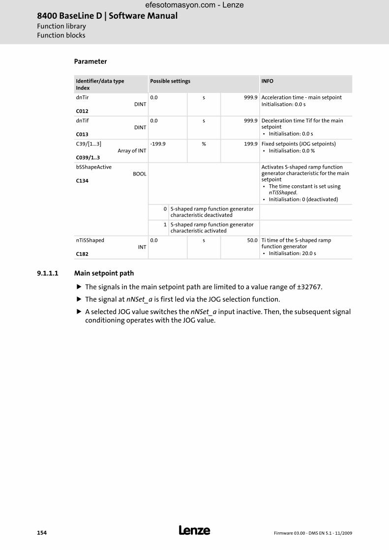
8400 BaseLine D | Software ManualFunction libraryFunction blocks
154 L Firmware 03.00 - DMS EN 5.1 - 11/2009
Parameter
9.1.1.1 Main setpoint path
The signals in the main setpoint path are limited to a value range of ±32767.
The signal at nNSet_a is first led via the JOG selection function.
A selected JOG value switches the nNSet_a input inactive. Then, the subsequent signal conditioning operates with the JOG value.
Identifier/data typeIndex
Possible settings INFO
dnTirDINT
C012
0.0 s 999.9 Acceleration time - main setpointInitialisation: 0.0 s
dnTifDINT
C013
0.0 s 999.9 Deceleration time Tif for the main setpoint • Initialisation: 0.0 s
C39/[1...3]Array of INT
C039/1..3
-199.9 % 199.9 Fixed setpoints (JOG setpoints) • Initialisation: 0.0 %
bSShapeActiveBOOL
C134
Activates S-shaped ramp function generator characteristic for the main setpoint • The time constant is set using
nTiSShaped. • Initialisation: 0 (deactivated)
0 S-shaped ramp function generator characteristic deactivated
1 S-shaped ramp function generator characteristic activated
nTiSShapedINT
C182
0.0 s 50.0 Ti time of the S-shaped ramp function generator • Initialisation: 20.0 s
efesotomasyon.com - Lenze

Firmware 03.00 - DMS EN 5.1 - 11/2009 L 155
8400 BaseLine D | Software ManualFunction libraryFunction blocks
9.1.1.2 JOG setpoints
JOG setpoints are constant values which are stored in the memory under C39/1 ... C39/3.
The JOG setpoints can be called binary-coded using the bJog1 ... bJog2 selection inputs so that 3 options are available.
The main setpoint nNSet_a must be freely defined for bJog1 ... bJog2 = FALSE.
The number of selection inputs to be assigned depends on the number of JOG setpoints required.
9.1.1.3 Setpoint inversion
The output signal of the JOG function is led via an inverter.
The sign of the setpoint changes if bNSetInv is set to TRUE.
UsedMain setpointbJog2 bJog1
FALSE FALSE nNSet_a
FALSE True C39/1
True FALSE C39/2
True True C39/3
efesotomasyon.com - Lenze

8400 BaseLine D | Software ManualFunction libraryFunction blocks
156 L Firmware 03.00 - DMS EN 5.1 - 11/2009
9.1.1.4 Ramp function generator for the main setpoint
Afterwards, the setpoint is led via a ramp function generator with linear characteristic. Theramp function generator transfers setpoint step-changes at the input to a ramp.
[9.1] Acceleration and deceleration times
9.1.1.5 S-shaped ramp
A PT1 element is connected downstream of the linear ramp function generator. Thisarrangement implements an S-shaped ramp for a nearly jerk-free acceleration anddeceleration.
The PT1 element is switched off/on using bSShapeActive.
The time constant is set using nTiSShaped.
w1, w2 = change of the main setpoint as a function of tir or tifRFG-OUT = output of the ramp function generator
RFG-OUT
100 %
w2
w1
t0 %
t ir t ir
Tir Tir
Tir tir100 %
w2 w1–----------------------⋅= Tif tif
100 %w2 w1–----------------------⋅=
efesotomasyon.com - Lenze

Firmware 03.00 - DMS EN 5.1 - 11/2009 L 157
8400 BaseLine D | Software ManualFunction libraryFunction blocks
9.1.2 L_MPot
This FB replaces a hardware motor potentiometer and can be used as an alternativesetpoint source which is controlled via two inputs.
The signal is output via a ramp function generator with linear ramps.
The acceleration and deceleration times are set via parameters.
The potentiometer function is selected via the Function parameter.
Inputs
Outputs
Identifier/data type Information/possible settings
bEnableC701/11
BOOL
Change-over of motor potentiometer functionInput bEnable and code C806 bEnableInternal are ORed.
True The motor potentiometer function is active, setpoint can be changed via bUp and bDown. • With a change-over to TRUE, the value applied to nIn_a is
automatically transferred to the motor potentiometer.
FALSE The value applied to nIn_a is output at nOut_a.
nIn_aC700/1
INT
When bEnable = FALSE, the analog input signal nIn_ is switched to the nOut_a output.
bUpC701/8
BOOL
Increase output signal
True The nOut_a output signal runs to its upper limit value (nHighLimit). • If the bDown input is simultaneously set to TRUE, the nOut_a
output signal is not changed.
bDownC701/9
BOOL
Reduce output signal
True The nOut_a output signal runs to its lower limit value (nLowLimit). • If the bUp input is simultaneously set to TRUE, the nOut_a output
signal is not changed.
bInActC701/10
BOOL
Deactivate motor potentiometer function • This input has the highest priority. • When the motor potentiometer is deactivated, the nOut_a output signal follows
the function set with Function.
True Motor potentiometer function is deactivated.
Identifier/data type Value/meaning
nOut_aINT
Output signal
L_MPot
nOut_a
bUp
bDown
bInAct
dnActRetain dnActRetain
0
1
C806
nln_a
bEnable
C804C805
C800C802
C801C803
CTRL
efesotomasyon.com - Lenze

8400 BaseLine D | Software ManualFunction libraryFunction blocks
158 L Firmware 03.00 - DMS EN 5.1 - 11/2009
Parameter
Identifier/data typeIndex
Possible settings INFO
dnActRetainDINT
Saves the current setpoint
nHighLimitC800
INT
-199.9 % 199.9 Upper limit • Initialisation: 100.0 %
nLowLimitC801
INT
-199.9 % 199.9 Lower limit • Initialisation: -100.0 %
wTirC802
WORD
1 0.1 s 6000 Acceleration time - main setpoint (Tir) • 10 ≡ 1 s • Initialisation: 10 s
wTifC803
WORD
1 0.1 s 6000 Deceleration time Tif • 10 ≡ 1 s • Initialisation: 10 s
FunctionC804
BYTE
Function selection • Initialisation: 0
0 No further action; nOut_a retains its value.
1 The motor potentiometer returns to 0 % with the deceleration time Tif.
2 The motor potentiometer runs to the lower limit value with the deceleration time Tif (nLowLimit)
3 The motor potentiometer output immediately changes to 0 %
Important for the emergency stop function
4 The motor potentiometer output immediately changes to the lower limit value (nLowLimit)
5 The motor potentiometer runs to the upper limit value with the acceleration time Tir (nHighLimit)
byInitFunctionC805
BYTE
Behaviour after mains power-up • Initialisation: 0
0 The output value being output during mains power-up, is saved non-volatilely in the internal memory of the controller. It will be reloaded during mains power-up.
1 The lower limit (nLowLimit) is loaded during mains power-up.
2 An output value = 0 % is loaded during mains power-up.
efesotomasyon.com - Lenze

Firmware 03.00 - DMS EN 5.1 - 11/2009 L 159
8400 BaseLine D | Software ManualFunction libraryFunction blocks
9.1.2.1 Activation & control of motor potentiometer
When bInAct is set to FALSE, the motor potentiometer is activated.
The currently active function depends on the current output signal nOut_a, the limit values set and the control signals at bUp and bDown.
When the nOut_a output signal is outside the limits set, the output signal runs to the next limit with the Ti times set. This process is independent of the control signals at bUp and bDown.
When the nOut_a output signal is inside the limits set, the output signal changes according to the control signals at bUp and bDown.
[9.2] Example: Control of the motor potentiometer
nOut_a
t
t
TRUE
FALSE
bUp
t
TRUE
FALSE
bDown
nHighLimit
nLowLimit
0
wTir
wTir
wTif
wTir
bUp bDown bInact Function
FALSE FALSE FALSE The nOut_a output signal remains unchanged.
FALSE True The nOut_a output signal runs to its upper limit value (nHighLimit).
True FALSE The nOut_a output signal runs to its lower limit value (nLowLimit).
True True The nOut_a output signal remains unchanged.
- - True The motor potentiometer function is deactivated. The nOut_a output signal responds according to the function selected via Function.
efesotomasyon.com - Lenze

8400 BaseLine D | Software ManualFunction libraryFunction blocks
160 L Firmware 03.00 - DMS EN 5.1 - 11/2009
9.1.2.2 Deactivation of motor potentiometer
When the motor potentiometer is deactivated by setting bInAct to TRUE, the nOut_aoutput signal responds according to the function selected via Function.
[9.3] Example: Deactivation of the motor potentiometer when the function 1, C804 = 1, has been selected
9.1.2.3 Save current output value after mains failure
To save the last actual value at nOut_a after a mains failure, declare a RETAIN variable andcombine this with the FB instance as shown in the following illustration:
This variable always saves the current value at nOut_a. Even in case of mains failure the variable keeps the value.
When the mains is switched on again, the value saved in the variable is read into the FB L_MPOT and processed as starting value.
When the motor potentiometer is deactivated, nOut_a is reduced to 0 % with the deceleration time wTif. If it is activated again, nOut_a is increased again to nLowLimit with the acceleration time wTir.
nOut_a
t
t
TRUE
FALSE
bUp
t
TRUE
FALSE
bDown
nHighLimit
nLowLimit
0
wTir
wTif
wTir
t
TRUE
FALSE
bInAct
wTif
wTif� �
VAR RETAIN
L_MPot
nOut_a
bUp
bDown
bInAct
dnActRetain dnActRetain
0
1
C806
nln_a
bEnable
C804C805
C800C802
C801C803
CTRL
VAR RETAIN
efesotomasyon.com - Lenze

Firmware 03.00 - DMS EN 5.1 - 11/2009 L 161
8400 BaseLine D | Software ManualFunction libraryFunction blocks
9.1.3 L_PCTRL
This function extension is available from software version 3.0!
This FB is a PID controller and can be used for various control tasks (e.g. as dancer positioncontroller, tension controller, or pressure controller).
Available function blocks: 1
The FB is provides with the following functions:
Adjustable control algorithm (P, PI, PID)
Ramp function generator for preventing setpoint step-changes at the input
Limitation of the controller output
Factorisation of the output signal
Vp adaptation
Integral action component can be switched off
L_PCTRL
bActEqSet
bIOff
nAct_a
bInAct
bEnableInfluenceRamp
nInfluence_a
nOut_a
nNSet_a
nSet_a
nAdapt_a
C00225
C00226
C00227
C00228
C00243
C00244
1
C00245
C00242
0
0
0
2
2
2
1
1
1
3
3
3
C00223TnC00222Vp
C00224Kd
efesotomasyon.com - Lenze

8400 BaseLine D | Software ManualFunction libraryFunction blocks
162 L Firmware 03.00 - DMS EN 5.1 - 11/2009
Inputs
Outputs
Parameter
Identifier/data type Information/possible settings
nNSet_aINT
Speed setpoint
nAdapt_aINT
Reduction of the gain (nVp) by the value applied (in %) • Internal limitation to ±32767 • Changes can be done online.Example: When nVp = 2.0 and nVpadapt = 75 % ((75/100) x 16384 = 12288), the gain factor results in: 2.0 x 12288 = 24576
nSet_aINT
Sensor setpoint (process setpoint) in the operating mode nMode = 1 and 3 • Internal limitation to ± 199.9 %Process setpoint in operating mode nMode = 2 • Internal limitation to ± 199.9 %
nAct_aINT
Speed or actual sensor value (actual process value) • Internal limitation to ± 199.9 %
bInActBOOL
Deactivate process controller temporarily • Changes can be done online.Note: This input is not connected with the application NCTRL.
True Process controller is deactivated, the internal PID-component is switched off.
bIOffBOOL
Switch off the I-component of the process controller • Changes can be done online.
True I-component of the process controller is switched off
nInfluence_aINT
• Internal limitation to ±32767 • nInfluence_a serves to limit the influencing factor of the PID controller contained
in the FB to a required value (- 199.9 % ... + 199.9 %).
nEnableInfluenceRampINT
True Influencing factor of the PID controller is ramped up to the nInflu_a value.
FALSE Influencing factor of the PID controller is ramped down to "0".
Identifier/data type Value/meaning
nOut_aINT
Output signal • 16384 ≡ 100 %
bActEqSetINT
Active: Setpoint and actual value are identical, no system deviation available
Identifier/data typeIndex
Possible settings Info
VpINT
C00222
0.1 0.1 500 Gain Vp • Initialisation: 1.0
TnINT
20 ms 6000 Reset time Tn • Initialisation: 400 ms
KdINT
C00224
0 0.1 5 Differential component Kd • Initialisation: 0.0
efesotomasyon.com - Lenze

Firmware 03.00 - DMS EN 5.1 - 11/2009 L 163
8400 BaseLine D | Software ManualFunction libraryFunction blocks
MaxLimitDINT
C00225
-199.99 % +199.99 Maximum value of the PID operating range • Initialisation: 199.99 %
MinLimitDINT
C00226
-199.99 % +199.99 Minimum value of the PID operating range • Initialisation: -199.99 %
Acceleration timeDINT
C00227
0.000 s 999.999 Acceleration time for the ramp at the PID output (should be set as steep as possible) • Initialisation: 0.010 s
Deceleration timeDINT
C00228
0.000 s 999.999 Deceleration time for the ramp at the PID output • Initialisation: 0.010 s
Operating modeC00242
Value range of the output signal • Initialisation: 0
0 Off The setpoint applied to the input nNSet_a is output without any changes at the output nOut_a.
1 Additive + feedforward control The setpoint is picked off at the input nNSet_a. Simultaneously, the setpoint is added to the output value of the PID-component and then output at nOut_a.
2 PID as a setpoint generator The setpoint is picked off at the input nSet_a. The input nNSet_a is not used. There is no additive linking at the output.
3 PID setpoint from L_NSet_1 The setpoint is picked off at the input nNSet_a. The input nSet_a is not used. There is no additive linking at the output.
Influence acceleration timeC00243
0.000 s 999.999 Acceleration time Tir for the influence value • Initialisation: 5 s
Influence deceleration timeC00244
0.000 s 999.999 Deceleration time Tif for the influence value • Initialisation: 5 s
Identifier/data typeIndex
Possible settings Info
efesotomasyon.com - Lenze

8400 BaseLine D | Software ManualFunction libraryFunction blocks
164 L Firmware 03.00 - DMS EN 5.1 - 11/2009
9.1.3.1 Control characteristic
The PID algorithm is active in the Lenze setting.
Differential component Kd
The Kd component can be deactivated by setting nKd = 0.0. This makes the controller a PIcontroller (or P controller if the integral action component is switched off as well).
Integral action component
You can switch off the I-component by
setting bIOff to TRUE or
entering Tn = 6000 s (max. value).
The I-component can be switched on and off online.
Reset time Tn
nTn serves to parameterise the reset time.
Gain Vp
The Vp gain is defined via nAdapt_a:
[9.4] Definition of Vp gain via nAdapt_a
The input value is led via a linear characteristic. The slope of the characteristic is defined with nVp (upper limit) and the value "0" (lower limit). The value in nVp applies if the input value is +100 % (100 % = 16384)
Vp
0 100 % nAdapt_a
nVp
efesotomasyon.com - Lenze

Firmware 03.00 - DMS EN 5.1 - 11/2009 L 165
8400 BaseLine D | Software ManualFunction libraryFunction blocks
9.1.3.2 Ramp function generator
The PID output is led via a ramp function generator with linear characteristic. This servesto transfer setpoint step-changes at the PID output into a ramp which should be as steepas possible.
[9.5] Acceleration and deceleration times
tir and tif are the desired times for changing between w1 and w2.
The ramps for acceleration and deceleration can be set individually.
– Acceleration time tir with C00227
– Deceleration time tif with C00228
The tir/tif values are converted into the required Ti times according to the following formula:
The ramp function generator is immediately set to "0" by setting bInAct to TRUE.
9.1.3.3 Value range of the output signal
The output signal and thus the operating range of the PID-component can be limited with the parameters nMaxLimit and nMinLmit (- 199.9%...+ 199.9%)
9.1.3.4 Evaluation of the output signal
The limitation is followed by an evaluation of the output signal via nInfluence_a.
This evaluation is activated or suppressed along a ramp via the input bEnableInfluenceRamp. The ramp times are set with the parameters "Influence acceleration time" and "Influence deceleration time" (C00243 / C00244).
w1, w2 = change of the main setpoint as a function of tir and tifRFG-OUT = output of the ramp function generator
RFG-OUT
100 %
w2
w1
t0 %
t ir t if
Tir Tif
Tir tir100 %
w2 w1–----------------------⋅= Tif tif
100 %w2 w1–----------------------⋅=
efesotomasyon.com - Lenze
8400 BaseLine D | Software ManualFunction libraryFunction blocks
166 L Firmware 03.00 - DMS EN 5.1 - 11/2009
9.1.3.5 Deactivation of the process controller
bInAct = TRUE deactivates the process controller. This serves to
– set the PID output = 0,
– set the integral action component = 0,
– set the ramp function generator = 0.
A setpoint executed in mode 1 of the input nNSet_a, however, will still be output.
efesotomasyon.com - Lenze

Firmware 03.00 - DMS EN 5.1 - 11/2009 L 167
8400 BaseLine D | Software ManualFunction libraryFunction blocks
9.1.4 L_RLQ
This FB combines the selection of a direction of rotation with the QSP function with wirebreak protection.
Available function blocks: 1
Inputs
Outputs
Function
[9.6] Truth table of the FB L_RLQ, 0 = FALSE, 1 = TRUE
Identifier/data type Information/possible settings
bCwBOOL
Input • TRUE = CW rotation
bCCwBOOL
Input • TRUE = CCW rotation
Identifier/data type Value/meaning
bQSPBOOL
Output signal for QSP (quick stop)
bCwCcwBOOL
Output signal for CW/CCW rotation • TRUE = CCW rotation
Inputs Outputs Info
bCw bCcw bCwCcw bQSP
True True FALSE True Only if both inputs are applied with a TRUE signal at the moment of switch-on, the outputs have these state!
FALSE FALSE FALSE True If only one of the inputs has the TRUE status, this part of the truth table applies
*) no change of the original status.
True FALSE FALSE FALSE
FALSE True True FALSE
True True *)
bQSP
bCwCCwbCw
bCcW
L_RLQ
Q
Q
1S
1R
efesotomasyon.com - Lenze

8400 BaseLine D | Software ManualFunction libraryFunction blocks
168 L Firmware 03.00 - DMS EN 5.1 - 11/2009
9.1.5 LS_DisFree
This FB serves to display any 16-bit process signal on display codes.
Inputs
Parameter
Identifier/data type Information/possible settings
wDis01 ... wDis04C620/5 ... 8
WORD
Input
Identifier/data typeIndex
Possible settings INFO
C481/1 ... 4 0x0000 0xFFFF General 16-bit signal • Read only
wDis01
wDis02
wDis03
wDis04
C481/1
C481/2
C481/3
C481/4
LS_DisFree
efesotomasyon.com - Lenze

Firmware 03.00 - DMS EN 5.1 - 11/2009 L 169
8400 BaseLine D | Software ManualFunction libraryFunction blocks
9.1.6 LS_DisFree_a
This FB serves to display four percentage analog process signals on display codes.
Inputs
Parameter
Identifier/data type Information/possible settings
nDis01_a ... nDis04_aC620/9 ... 12
INT
Input
Identifier/data typeIndex
Possible settings INFO
C482/1 ... 4 - 199.9 % + 199.9 % Process signal • Read only
nDis01
nDis02
nDis03
nDis04
C482/1
C482/2
C482/3
C482/4
LS_DisFree_a
efesotomasyon.com - Lenze
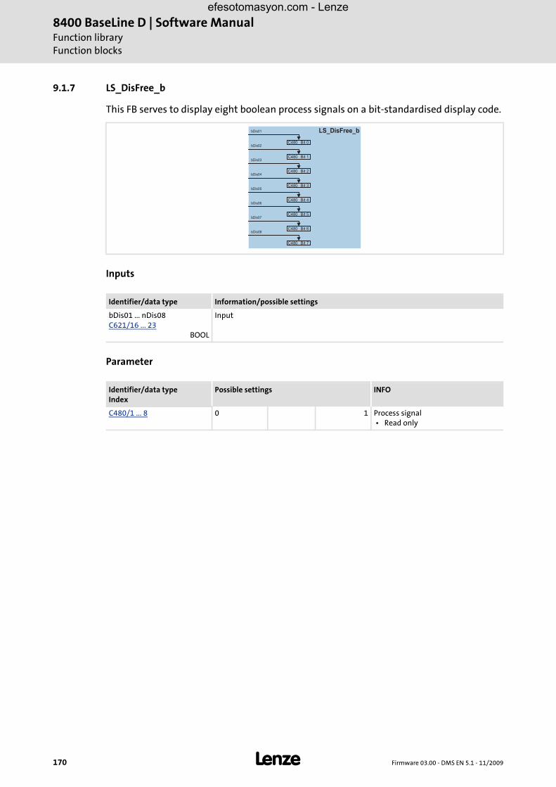
8400 BaseLine D | Software ManualFunction libraryFunction blocks
170 L Firmware 03.00 - DMS EN 5.1 - 11/2009
9.1.7 LS_DisFree_b
This FB serves to display eight boolean process signals on a bit-standardised display code.
Inputs
Parameter
Identifier/data type Information/possible settings
bDis01 ... nDis08C621/16 ... 23
BOOL
Input
Identifier/data typeIndex
Possible settings INFO
C480/1 ... 8 0 1 Process signal • Read only
bDis02
bDis01
bDis03
bDis04
bDis05
bDis06
bDis07
bDis08
C480
C480
C480
C480
C480
C480
C480
C480
Bit 1
Bit 0
Bit 2
Bit 3
Bit 4
Bit 5
Bit 6
Bit 7
LS_DisFree_b
efesotomasyon.com - Lenze

Firmware 03.00 - DMS EN 5.1 - 11/2009 L 171
8400 BaseLine D | Software ManualFunction libraryFunction blocks
9.1.8 LS_ParFix
This system block provides the user with fixed values which can be used in theinterconnection for parameterisation purposes.
Outputs
The output values are fixed and can therefore not be parameterised.
bTrue
nPos100_a
nNeg100_a
nPos199_99_a
nPos199_99_a
w65535
LS_ParFix
efesotomasyon.com - Lenze

8400 BaseLine D | Software ManualFunction libraryFunction blocks
172 L Firmware 03.00 - DMS EN 5.1 - 11/2009
9.1.9 LS_ParFree_b
This system block provides 16 digital signals which can be parameterised separately by theuser.
Outputs
Parameter
Identifier/data type Information/possible settings
bPar01 ... bPar16BOOL
Output
Identifier/data typeIndex
Possible settings INFO
C470/1 ... 16 0 "FALSE" signal is output
1 "TRUE" signal is output
bPar01_a
bPar02_a
bPar03_a
bPar04_a
bPar05_a
bPar06_a
bPar07_a
bPar08_a
bPar09_a
bPar10_a
bPar11_a
bPar12_a
bPar13_a
bPar14_a
bPar15_a
bPar16_a
LS_ParFree_b
efesotomasyon.com - Lenze

Firmware 03.00 - DMS EN 5.1 - 11/2009 L 173
8400 BaseLine D | Software ManualFunction libraryFunction blocks
9.1.10 LS_ParFree_a
This system block provides 4 analog signal which can be parameterised separately by theuser.
Outputs
Parameter
Identifier/data type Information/possible settings
nPar1_a ... nPar4_aINT
Output
Identifier/data typeIndex
Possible settings INFO
C472/1 ... 4 -199.9 % +199.9
nPar1_a
nPar2_a
nPar3_a
nPar4_a
LS_ParFree_a
efesotomasyon.com - Lenze

8400 BaseLine D | Software ManualFunction libraryFunction blocks
174 L Firmware 03.00 - DMS EN 5.1 - 11/2009
efesotomasyon.com - Lenze
Firmware 03.00 - DMS EN 5.1 - 11/2009 L 175
8400 BaseLine D | Software ManualParameter reference
10 Parameter reference
All parameters for controller parameter setting and monitoring are called "codes".
The codes are numbered and indicated by the prefix "C" before the code, e.g. "C00002".
For the sake of clarity, some codes contain "subcodes" for saving parameters. This Manual uses a slash "/" as a separator between code and subcode, e.g. C00118/3".
The terms "code" and "subcode" generally correspond to the terms "index" and "subindex" and "parameter" and "subparameter".
In case of the 8400 frequency inverter, the following functions can be carried out via codes:
– Setting of setpoints, e.g. acceleration time.
– Display of actual values, e.g. actual motor current.
– Configuration of signal links, e.g. assignment of the digital input terminals to control inputs of the technology application.
– Configuration of monitoring functions, e.g. selection of the error response and setting of trigger thresholds.
Parameters which are only available in the controller from a certain software versiononwards, are marked with a corresponding note in the parameter description ("fromversion xx.xx.xx").
The parameter descriptions are based on the software version V03.00.00
Tip!
For quick reference of a parameter with a certain name, simply use the index of the online documentation. The index always contains the corresponding code in parentheses after the name.
For general information on how to read and change parameters, please see the online documentation for the »Engineer«.
efesotomasyon.com - Lenze

8400 BaseLine D | Software ManualParameter referenceStructure of the parameter descriptions
176 L Firmware 03.00 - DMS EN 5.1 - 11/2009
10.1 Structure of the parameter descriptions
Each parameter is described in the Parameter list in the form of a table which consists ofthe following three areas:
Table header
The table header contains the following general information:
Parameter number (Cxxxxx)
Parameter name (display text in »Engineer» and keypad)
Data type
Parameter index in decimal and hexadecimal notation for access via a fieldbus, e.g. system bus (CAN).
Tip!
The parameter index is calculated as follows:
• Index [dec] = 24575 - code
• Index [hex] = 0x5FFF - code
Example for code C00005:
• Index [dec] = 24575 - 5 = 24570
• Index [hex] = 0x5FFF - 0x{5} = 0x5FFA
Table contents
The table contains further general explanations & notes on the parameter and the possiblesettings the representation of which depends on the parameter type:
Parameters with read-only access
Parameters with write access
Table footer
The table footer contains the Parameter attributes.
efesotomasyon.com - Lenze

Firmware 03.00 - DMS EN 5.1 - 11/2009 L 177
8400 BaseLine D | Software ManualParameter reference
Structure of the parameter descriptions
10.1.1 Data type
The following data types are available for parameters:
10.1.2 Parameters with read-only access
Parameters for which the "write access" attribute has not been set can only be read and notbe changed by the user.
Description structure
Representation in the »Engineer«
The »Engineer« displays these parameters with a grey background or, with an onlineconnection, with a pale-yellow background:
Data type Meaning
INTEGER_8 8-bit value with sign
INTEGER_16 16-bit value with sign
INTEGER_32 32-bit value with sign
INTEGER_64 64-bit value with sign
UNSIGNED_8 8-bit value without sign
UNSIGNED_16 16-bit value without sign
UNSIGNED_32 32-bit value without sign
UNSIGNED_64 64-bit value without sign
FLOATING_POINT 32-bit floating point number
VISIBLE_STRING String of digits from printable digits
OCTET_STRING String of digits from any digits
BITFIELD_8 8-bit value, bit-coded
BITFIELD_16 16-bit value, bit-coded
BITFIELD_32 32-bit value, bit-coded
Parameter | Name:
Cxxxxx | _____________Data type: _______
Index: _______
Description
Display range (min. value | unit | max. value)
Read access Write access CINH PLC STOP No transfer COM MOT Scaling factor: 1
efesotomasyon.com - Lenze

8400 BaseLine D | Software ManualParameter referenceStructure of the parameter descriptions
178 L Firmware 03.00 - DMS EN 5.1 - 11/2009
10.1.3 Parameters with write access
Only parameters with a check mark ( ) in front of the "write access" attribute can bechanged by the user. The Lenze setting for these parameters is printed in bold.
The settings are either selected by means of a selection list or through direct value entry.
Values outside the valid setting range are represented in red in the »Engineer«.
10.1.3.1 Parameters with setting range
Description structure
Parameter setting in the »Engineer«
In the »Engineer«, parameters are set by entering the desired value into the input field:
10.1.3.2 Parameters with selection list
Description structure
Parameter | Name:
Cxxxxx | _____________Data type: _______
Index: _______
Description
Setting range (min. value | unit | max. value) Lenze setting
Read access Write access CINH PLC STOP No transfer COM MOT Scaling factor: 1
Parameter | Name:
Cxxxxx | _____________Data type: _______
Index: _______
Description
Selection list (Lenze setting printed in bold)
1
2
3
Read access Write access CINH PLC STOP No transfer COM MOT Scaling factor: 1
efesotomasyon.com - Lenze

Firmware 03.00 - DMS EN 5.1 - 11/2009 L 179
8400 BaseLine D | Software ManualParameter reference
Structure of the parameter descriptions
Parameter setting in the »Engineer«
In the »Engineer«, a list field is used for parameter setting:
10.1.3.3 Parameters with bit-coded setting
Description structure
Parameter setting in the »Engineer«
The »Engineer« uses a dialog box for parameter setting in which the individual bits can beset or reset. Alternatively, the value can be entered as a decimal or hexadecimal value:
Parameter | Name:
Cxxxxx | _____________Data type: _______
Index: _______
Description
Value is bit-coded:
Bit 0
...
Bit 31
Read access Write access CINH PLC STOP No transfer COM MOT Scaling factor: 1
efesotomasyon.com - Lenze

8400 BaseLine D | Software ManualParameter referenceStructure of the parameter descriptions
180 L Firmware 03.00 - DMS EN 5.1 - 11/2009
10.1.3.4 Parameters with subcodes
Description structure
Parameter setting in the »Engineer«
The »Engineer« parameter list displays each subcode individually. They are parameterisedas described in the previous chapters.
10.1.4 Parameter attributes
The table footers contain the parameter attributes:
Parameter | Name:
Cxxxxx | _____________Data type: _______
Index: _______
Description
Setting range (min. value | unit | max. value)
Subcodes Lenze setting
Cxxxxx/1
Cxxxxx/2
Cxxxxx/3
Cxxxxx/4
Read access Write access CINH PLC STOP No transfer COM MOT Scaling factor: 1
Read access Write access CINH PLC STOP No transfer COM MOT Scaling factor: 1
Attribute Meaning
Read access Read access to parameter possible.
Write access Write access to parameter possible. • Please also observe the following attributes:
CINH Parameter value can only be changed when the controller is inhibited.
PLC STOP Parameter value can only be changed when the application is stopped.
No transfer Parameter is not transferred to controller when the command Download parameter set is executed.
COM Communication-relevant parameter • this parameter is relevant for parameter data transfer via the system bus (CAN)
MOT Parameter of the motor control
efesotomasyon.com - Lenze

Firmware 03.00 - DMS EN 5.1 - 11/2009 L 181
8400 BaseLine D | Software ManualParameter reference
Structure of the parameter descriptions
Scaling factor
The "scaling factor" is important for parameter access via a bus system.
Example 1: The value "654" read via a bus system of the parameter C00028/1 (AIN1: inputvoltage) must be divided by the corresponding scaling factor "100" to obtain the realdisplay value "6.54 V".
[10-1] Conversion formula for read access via bus system
Example 2: In order to set the parameter C00012 (acceleration time - main setpoint) to thevalue "123.45 %" via a bus system, the integer value "12345" must be transferred, i.e. thevalue to be set must be multiplied by the corresponding scaling factor "100".
[10-2] Conversion formula for write access via bus system
Signal type Scaling factor Resolution Value range
Analog (scaled) 100 16 bits signed ± 199.99 %
Angular velocity 1 16 bits signed ± 32767 increments/ms
Position in [units] 10000 32 bits signed ± 214748.3647 [units]
Digital (BOOL) 1 8 bits unsigned 0 ≡ FALSE; 1 ≡ TRUE
Time 1000 16 bits unsigned 0 ... 999.000 s
Selection value 1 16 bits unsigned 0...65535
Read value (via bus system)Scaling factor
----------------------------------------------------------------------- Indicated value (Engineer)=
Value to be written (via bus system) Value to be set Scaling factor⋅=
efesotomasyon.com - Lenze
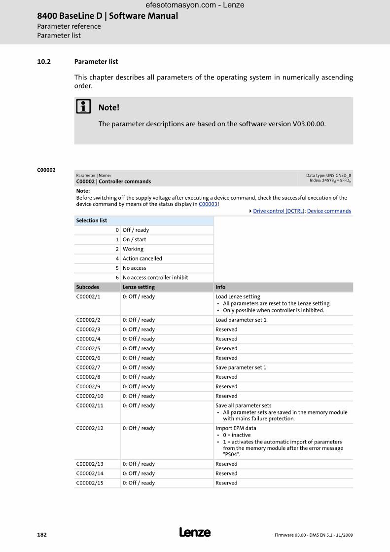
8400 BaseLine D | Software ManualParameter referenceParameter list
182 L Firmware 03.00 - DMS EN 5.1 - 11/2009
10.2 Parameter list
This chapter describes all parameters of the operating system in numerically ascendingorder.
C00002
Note!
The parameter descriptions are based on the software version V03.00.00.
Parameter | Name:
C00002 | Controller commandsData type: UNSIGNED_8
Index: 24573d = 5FFDh
Note:Before switching off the supply voltage after executing a device command, check the successful execution of the device command by means of the status display in C00003!
Drive control (DCTRL): Device commands
Selection list
0 Off / ready
1 On / start
2 Working
4 Action cancelled
5 No access
6 No access controller inhibit
Subcodes Lenze setting Info
C00002/1 0: Off / ready Load Lenze setting • All parameters are reset to the Lenze setting. • Only possible when controller is inhibited.
C00002/2 0: Off / ready Load parameter set 1
C00002/3 0: Off / ready Reserved
C00002/4 0: Off / ready Reserved
C00002/5 0: Off / ready Reserved
C00002/6 0: Off / ready Reserved
C00002/7 0: Off / ready Save parameter set 1
C00002/8 0: Off / ready Reserved
C00002/9 0: Off / ready Reserved
C00002/10 0: Off / ready Reserved
C00002/11 0: Off / ready Save all parameter sets • All parameter sets are saved in the memory module
with mains failure protection.
C00002/12 0: Off / ready Import EPM data • 0 = inactive • 1 = activates the automatic import of parameters
from the memory module after the error message "PS04".
C00002/13 0: Off / ready Reserved
C00002/14 0: Off / ready Reserved
C00002/15 0: Off / ready Reserved
efesotomasyon.com - Lenze

Firmware 03.00 - DMS EN 5.1 - 11/2009 L 183
8400 BaseLine D | Software ManualParameter reference
Parameter list | C00002
C00002/6 0: Off / ready Reserved
C00002/7 0: Off / ready Save parameter set 1
C00002/8 0: Off / ready Reserved
C00002/9 0: Off / ready Reserved
C00002/10 0: Off / ready Reserved
C00002/11 0: Off / ready Save all parameter sets • All parameter sets are saved in the memory module
with mains failure protection.
C00002/12 0: Off / ready Import EPM data • 0 = inactive • 1 = activates the automatic import of parameters
from the memory module after the error message "PS04".
C00002/13 0: Off / ready Reserved
C00002/14 0: Off / ready Reserved
C00002/15 0: Off / ready Reserved
efesotomasyon.com - Lenze

8400 BaseLine D | Software ManualParameter referenceParameter list | C00003
184 L Firmware 03.00 - DMS EN 5.1 - 11/2009
C00003
C00006
C00002/29 0: Off / ready Reserved
C00002/30 0: Off / ready Reserved
C00002/31 0: Off / ready Reserved
C00002/32 0: Off / ready Reserved
Read access Write access CINH PLC STOP No transfer COM MOT Scaling factor: 1
Parameter | Name:
C00002 | Controller commandsData type: UNSIGNED_8
Index: 24573d = 5FFDh
Parameter | Name:
C00003 | Status of last device commandData type: UNSIGNED_8
Index: 24572d = 5FFCh
Status of the device command executed last (C00002).
Note:Before switching off the supply voltage after executing a device command, check the successful execution of the device command by means of this status display!
Drive control (DCTRL): Device commands
Selection list (read only) Info
0 Successful Device command has been executed successfully.
1 Command unknown Device command is implausible or not known in the system.
2 No access Access for required device command is not approved.
3 Time-out Processing of the device command could not be executed within the defined time (time-out).
Read access Write access CINH PLC STOP No transfer COM MOT Scaling factor: 1
Parameter | Name:
C00006 | Select motor controlData type: UNSIGNED_8
Index: 24569d = 5FF9h
Selection of motor control type (operating mode)Motor control (MCTRL): Selection of operating mode
Selection list (Lenze setting printed in bold) Info
4 SLVC: Vector control This control type is used for sensorless vector control of an asynchronous motor. • This control mode needs the motor parameters to be
set as exactly as possible!
6 VFCplus: V/f linear This control type is used for open-loop speed control of an asynchronous motor via a linear V/f characteristic and represents the most simple control type. • In order to set the V/f characteristic, the rated
frequency (C00089) and rated voltage (C00090) of the motor must be entered only.
8 VFCplus: V/f quadr This control type is used for open-loop speed control of an asynchronous motor via a square-law V/f characteristic. • In order to set the V/f characteristic, the rated
frequency (C00089) and rated voltage (C00090) of the motor must be entered only.
Read access Write access CINH PLC STOP No transfer COM MOT Scaling factor: 1
efesotomasyon.com - Lenze

Firmware 03.00 - DMS EN 5.1 - 11/2009 L 185
8400 BaseLine D | Software ManualParameter reference
Parameter list | C00007
C00007
C00010
Parameter | Name:
C00007 | Select control modeData type: UNSIGNED_16
Index: 24568d = 5FF8h
Configuration of the digital inputs
Selection list (Lenze setting printed in bold) Info
0 Wiring has changed This display appears if the defined configuration has been reparameterised via the connection parameters.
10 Terminal 0 The technology application is controlled using the digital input terminals of the controller. • DI1 = JOG 1/3 • DI2 = JOG 2/3 • DI3 = DCB • DI4 = R/L
12 Terminal 2 The technology application is controlled using the digital input terminals of the controller. • DI1 = JOG 1/3 • DI2 = JOG 2/3 • DI3 = QSP • DI4 = R/L
14 Terminal 11 The technology application is controlled using the digital input terminals of the controller. • DI1 = R/L • DI2 = DCB • DI3 = MPotUp • DI4 = MPotDown
16 Terminal 16 The technology application is controlled using the digital input terminals of the controller. • DI1 = JOG 1/3 • DI2 = JOG 2/3 • DI3 = R/QSP • DI4 = L/QSP
20 Keypad The technology application is controlled via the keypad: C00728: Setpoint selections C00002: Device commands C00003: Status of last device command Increase speed Reduce speed
21 PC The technology application is controlled using the "Free parameters" of the controller (PC control).
Read access Write access CINH PLC STOP No transfer COM MOT Scaling factor: 1
Parameter | Name:
C00010 | Minimum analog setpointData type: INTEGER_16
Index: 24565d = 5FF5h
From version 03.00.00
Setting range (min. value | unit | max. value)
0.0 % 100.0
Subcodes Lenze setting Info
C00010/1 0.0 % Min. analog setpoint
Read access Write access CINH PLC STOP No transfer COM MOT Scaling factor: 100
efesotomasyon.com - Lenze

8400 BaseLine D | Software ManualParameter referenceParameter list | C00011
186 L Firmware 03.00 - DMS EN 5.1 - 11/2009
C00011
C00012
C00013
C00015
C00016
Parameter | Name:
C00011 | Appl.: Reference speedData type: UNSIGNED_16
Index: 24564d = 5FF4h
Setting of the reference speed • In the controller, all speed-related signals are processed to one reference variable in percent. • Set a reference speed here that corresponds to 100 %.
Note:This is not a maximum limitation!All values in percent in the controller may be in the range of 0 ... 199.99 %.
Setting range (min. value | unit | max. value) Lenze setting
50 rpm 9999 1500 rpm
Read access Write access CINH PLC STOP No transfer COM MOT Scaling factor: 1
Parameter | Name:
C00012 | Accel. time - main setpointData type: UNSIGNED_32
Index: 24563d = 5FF3h
FB L_NSet_1: Acceleration time of the ramp generator for the main speed setpoint
Setting range (min. value | unit | max. value) Lenze setting
0.0 s 999.9 2.0 s
Read access Write access CINH PLC STOP No transfer COM MOT Scaling factor: 1000
Parameter | Name:
C00013 | Decel. time - main setpointData type: UNSIGNED_32
Index: 24562d = 5FF2h
FB L_NSet_1: Deceleration time of the ramp generator for the main speed setpoint
Setting range (min. value | unit | max. value) Lenze setting
0.0 s 999.9 2.0 s
Read access Write access CINH PLC STOP No transfer COM MOT Scaling factor: 1000
Parameter | Name:
C00015 | VFC: V/f base frequencyData type: UNSIGNED_16
Index: 24560d = 5FF0h
V/f base frequency for VFCplus operating mode • The motor voltage increases linearly with the frequency until the base frequency is reached. From this value on,
the motor voltage remains constant, the speed increases and the maximum torque decreases. • After the motor to be used has been selected from the motor catalogue, the suitable value can be entered
automatically. An automatic detection via the motor parameter identification is possible as well.
Setting range (min. value | unit | max. value) Lenze setting
7.5 Hz 999.9 50.0 Hz
Read access Write access CINH PLC STOP No transfer COM MOT Scaling factor: 10
Parameter | Name:
C00016 | VFC: Vmin boostData type: UNSIGNED_16
Index: 24559d = 5FEFh
Boost of the V/f voltage characteristic within a small speed or frequency range for the VFCplus operating mode • This may increase the starting torque. • After the motor to be used has been selected from the motor catalogue, the suitable value can be entered
automatically. An automatic detection via the motor parameter identification is possible as well.Motor control (MCTRL): Setting Vmin boost
Setting range (min. value | unit | max. value) Lenze setting
0.0 % 100.0 0.0 %
Read access Write access CINH PLC STOP No transfer COM MOT Scaling factor: 100
efesotomasyon.com - Lenze

Firmware 03.00 - DMS EN 5.1 - 11/2009 L 187
8400 BaseLine D | Software ManualParameter reference
Parameter list | C00018 |
C00018 |
C00019
C00021
C00022 |
Parameter | Name:
C00018 | Switching frequencyData type: UNSIGNED_8
Index: 24557d = 5FEDh
Selection of the pulse width modulated switching frequency transferred from the inverter to the motor • When a variable switching frequency is selected, the switching frequency may change as a function of the load
and rotational frequency.
Selection list (Lenze setting printed in bold)
1 4 kHz var./drive-optimised
2 8 kHz var./drive-optimised
3 16 kHz var./drive-optimised
5 2 kHz constant/drive-optimised
6 4 kHz constant/drive-optimised
7 8 kHz constant/drive-optimised
8 16 kHz constant/drive-optimised
21 8 kHz var/4 kHz min.
22 16 kHz var/4 kHz min.
23 16 kHz var/8 kHz min.
Read access Write access CINH PLC STOP No transfer COM MOT Scaling factor: 1
Parameter | Name:
C00019 | Auto-DCB: ThresholdData type: UNSIGNED_16
Index: 24556d = 5FECh
Setpoint speed threshold for the automatic DC injection brake • For speed setpoints with values below the thresholds a DC current is injected or the motor is not supplied with
current, depending on the setting.
Setting range (min. value | unit | max. value) Lenze setting
0 rpm 9999 3 rpm
Read access Write access CINH PLC STOP No transfer COM MOT Scaling factor: 1
Parameter | Name:
C00021 | Slip comp.Data type: INTEGER_16Index: 24554d = 5FEAh
Slip compensation for VFCplus and SLVC operating modes • An increase of the slip compensation causes a greater frequency and voltage increase when the machine is
loaded. • After the motor to be used has been selected from the motor catalogue, the suitable value can be entered
automatically. An automatic detection via the motor parameter identification is possible as well.Motor control (MCTRL): Optimising the operational performance by slip compensation
Setting range (min. value | unit | max. value) Lenze setting
-50.00 % 50.00 0.00 %
Read access Write access CINH PLC STOP No transfer COM MOT Scaling factor: 100
Parameter | Name:
C00022 | Imax in motor modeData type: UNSIGNED_16
Index: 24553d = 5FE9h
Maximum current in motor mode for all operating modes
Setting range (min. value | unit | max. value) Lenze setting
0.00 A 99.99 47.00 A
Read access Write access CINH PLC STOP No Transfer COM MOT Scaling factor: 100
efesotomasyon.com - Lenze

8400 BaseLine D | Software ManualParameter referenceParameter list | C00023
188 L Firmware 03.00 - DMS EN 5.1 - 11/2009
C00023
C00024 |
C00026
C00027
C00028 |
Parameter | Name:
C00023 | Imax in generator modeData type: INTEGER_16
Index: 24552d = 5FE8h
Maximum current in generator mode for all operating modes • 100 % ≡ Imax in motor mode (C00022)
Setting range (min. value | unit | max. value) Lenze setting
0.0 % 100.0 100.0 %
Read access Write access CINH PLC STOP No Transfer COM MOT Scaling factor: 100
Parameter | Name:
C00024 | Comparison value N_ActData type: INTEGER_16
Index: 24551d = 5FE7h
Threshold for the actual speed comparison • This parameter serves to set a threshold that is compared with the actual speed value. • When the value falls below this threshold, the bNactCompare output of the SB LS_DriveInterface switches to
TRUE. • Switching hysteresis = +1 %
Setting range (min. value | unit | max. value) Lenze setting
0.0 % 199.9 0.0 %
Read access Write access CINH PLC STOP No Transfer COM MOT Scaling factor: 100
Parameter | Name:
C00026 | AINx: OffsetData type: INTEGER_16
Index: 24549d = 5FE5h
Offset for analog inputI/O terminals
Setting range (min. value | unit | max. value)
-199.9 % 199.9
Subcodes Lenze setting Info
C00026/1 0.0 % AIN1: Offset
Read access Write access CINH PLC STOP No Transfer COM MOT Scaling factor: 100
Parameter | Name:
C00027 | AINx: GainData type: INTEGER_32
Index: 24548d = 5FE4h
Gain for analog inputI/O terminals
Setting range (min. value | unit | max. value)
-199.9 % 199.9
Subcodes Lenze setting Info
C00027/1 100.0 % AIN1: Gain
Read access Write access CINH PLC STOP No Transfer COM MOT Scaling factor: 100
Parameter | Name:
C00028 | AINx: Input voltageData type: INTEGER_16
Index: 24547d = 5FE3h
Display of the input voltage at the analog inputI/O terminals
Display range (min. value | unit | max. value)
-10.0 V 10.0
Subcodes Info
C00028/1 AIN1: Input voltage
Read access Write access CINH PLC STOP No Transfer COM MOT Scaling factor: 100
efesotomasyon.com - Lenze

Firmware 03.00 - DMS EN 5.1 - 11/2009 L 189
8400 BaseLine D | Software ManualParameter reference
Parameter list | C00029 |
C00029 |
C00033 |
C00034 |
C00036
Parameter | Name:
C00029 | AINx: Input currentData type: INTEGER_16
Index: 24546d = 5FE2h
Display of the input current at the analog input • When the analog input is configured for current measurement (C00034/1 = 1 or 2). • When C00034/1 is set = 2 (4 ... 20 mA), 0 ... 16 mA is displayed.
I/O terminals
Display range (min. value | unit | max. value)
0.0 mA 20.0
Subcodes Info
C00029/1 AIN1: Input current
Read access Write access CINH PLC STOP No Transfer COM MOT Scaling factor: 100
Parameter | Name:
C00033 | AINx: Output valueData type: INTEGER_16Index: 24542d = 5FDEh
Display of the output value in percent of the analog input amplifier • 100 % ≡ 16384 ≡ +10 V / +20 mA
I/O terminals
Display range (min. value | unit | max. value)
-199.9 % 199.9
Subcodes Info
C00033/1 AIN1: Output value
Read access Write access CINH PLC STOP No Transfer COM MOT Scaling factor: 100
Parameter | Name:
C00034 | AINx: ConfigurationData type: UNSIGNED_8
Index: 24541d = 5FDDh
Configuration of the analog input for current or voltage measurementI/O terminals
Selection list Info
0 0...+10 V Input signal is the voltage signal 0 V ... +10 V • 0 V ... +10 V ≡ 0 % ... +100 %
1 0...+5V With external load resistor (250 Ohms):Input signal is the current signal 0 mA ... 20 mA • 0 mA ... 20 mA ≡ 0 % ... +100 %
2 1...+5V (4...20mA) With external load resistor (250 Ohms):Input signal is the current signal 4 mA ... 20 mA • 4 mA ... 20 mA ≡ 0 % ... +100 % • The current loop is monitored for open circuit
(I < 4 mA) by the device .
Subcodes Lenze setting Info
C00034/1 0: 0...+10 V AIN1: Config.
Read access Write access CINH PLC STOP No transfer COM MOT Scaling factor: 1
Parameter | Name:
C00036 | DCB: CurrentData type: INTEGER_16Index: 24539d = 5FDBh
Current value in [%] for DC-injection braking • 100 % ≡ Imax in motor mode (C00022)
Setting range (min. value | unit | max. value) Lenze setting
0.0 % 150.0 50.0 %
Read access Write access CINH PLC STOP No transfer COM MOT Scaling factor: 100
efesotomasyon.com - Lenze

8400 BaseLine D | Software ManualParameter referenceParameter list | C00039 |
190 L Firmware 03.00 - DMS EN 5.1 - 11/2009
C00039 |
C00050 |
C00051 |
C00052 |
C00053 |
Parameter | Name:
C00039 | Fixed setpoint x (L_NSet_1 n-Fix)Data type: INTEGER_16Index: 24536d = 5FD8h
FB L_NSet_1: Fixed speed setpoints (Jog values) for the setpoint generator
Setting range (min. value | unit | max. value)
-199.9 % 199.9
Subcodes Lenze setting Info
C00039/1 40.0 % Fixed setpoint 1
C00039/2 60.0 % Fixed setpoint 2
C00039/3 80.0 % Fixed setpoint 3
Read access Write access CINH PLC STOP No transfer COM MOT Scaling factor: 100
Parameter | Name:
C00050 | MCTRL: Speed setpointData type: INTEGER_32Index: 24525d = 5FCDh
Display of the speed setpoint at the speed setpoint input of the motor control.
Display range (min. value | unit | max. value)
-9999 rpm 9999
Read access Write access CINH PLC STOP No transfer COM MOT Scaling factor: 1
Parameter | Name:
C00051 | MCTRL: Actual speed valueData type: INTEGER_32Index: 24524d = 5FCCh
Display of the actual speed value of the motor shaft
Note:The displayed value only corresponds to the real actual speed value of the motor shaft if an encoder is connected to the motor and the evaluation of the feedback signal has been set correctly ("Closed loop" operation).In case of operation without feedback, the signal is calculated from the motor control and thus may not correspond to the real actual speed.
Display range (min. value | unit | max. value)
-9999 rpm 9999
Read access Write access CINH PLC STOP No transfer COM MOT Scaling factor: 1
Parameter | Name:
C00052 | Motor voltageData type: UNSIGNED_16
Index: 24523d = 5FCBh
Display of the current motor voltage/output voltage of the inverter
Display range (min. value | unit | max. value)
0 V 1000
Read access Write access CINH PLC STOP No transfer COM MOT Scaling factor: 1
Parameter | Name:
C00053 | DC-bus voltageData type: UNSIGNED_16
Index: 24522d = 5FCAh
Display of the current DC-bus voltage
Display range (min. value | unit | max. value)
0 V 1000
Read access Write access CINH PLC STOP No transfer COM MOT Scaling factor: 1
efesotomasyon.com - Lenze

Firmware 03.00 - DMS EN 5.1 - 11/2009 L 191
8400 BaseLine D | Software ManualParameter reference
Parameter list | C00054 |
C00054 |
C00056 |
C00057 |
C00058 |
C00059 |
C00061
Parameter | Name:
C00054 | Motor currentData type: UNSIGNED_16
Index: 24521d = 5FC9h
Display of the current motor current /output current of the inverter
Display range (min. value | unit | max. value)
0.00 A 300.00
Read access Write access CINH PLC STOP No transfer COM MOT Scaling factor: 100
Parameter | Name:
C00056 | TorqueData type: INTEGER_32Index: 24519d = 5FC7h
Display of the current motor torque
Display range (min. value | unit | max. value)
-99.00 Nm 99.00
Subcodes Info
C00056/1 Torque setpoint • Only for SLVC operating mode.
C00056/2 Torque actual value • Estimated actual torque for all operating modes.
Read access Write access CINH PLC STOP No transfer COM MOT Scaling factor: 100
Parameter | Name:
C00057 | Maximum torqueData type: UNSIGNED_32
Index: 24518d = 5FC6h
Display of the maximum torque to be generated by the motor • The maximum torque to be generated by the motor depends on various factors, e.g. on Imax in motor mode
(C00022) and the motor type used.
Display range (min. value | unit | max. value)
0.0 Nm 999.9
Read access Write access CINH PLC STOP No transfer COM MOT Scaling factor: 100
Parameter | Name:
C00058 | Output frequencyData type: INTEGER_32Index: 24517d = 5FC5h
Display of the current output frequency
Display range (min. value | unit | max. value)
-655.0 Hz 655.0
Read access Write access CINH PLC STOP No transfer COM MOT Scaling factor: 100
Parameter | Name:
C00059 | Appl.: Reference frequency C11Data type: UNSIGNED_32
Index: 24516d = 5FC4h
Display of the field frequency which corresponds to the reference speed set in C00011.
Display range (min. value | unit | max. value)
0.0 Hz 999.9
Read access Write access CINH PLC STOP No transfer COM MOT Scaling factor: 100
Parameter | Name:
C00061 | Heatsink temperatureData type: INTEGER_16Index: 24514d = 5FC2h
Display of the current heatsink temperature
Display range (min. value | unit | max. value)
-50 °C 150
Read access Write access CINH PLC STOP No transfer COM MOT Scaling factor: 1
efesotomasyon.com - Lenze

8400 BaseLine D | Software ManualParameter referenceParameter list | C00064
192 L Firmware 03.00 - DMS EN 5.1 - 11/2009
C00064
C00066
C00073
C00074
C00081
Parameter | Name:
C00064 | Device utilisation (Ixt)Data type: INTEGER_16
Index: 24511d = 5FBFh
Display of the device utilisation Ixt in different time resolutions • If the value displayed here exceeds the threshold set in C00123, the fault message "OC5: Device overload (Ixt)"
is output and the fault response set in C00604 is executed (default setting: "Warning").
Display range (min. value | unit | max. value)
0 % 250
Subcodes Info
C00064/1 Device utilisation (Ixt) • Maximum value of the pulse utilisation (C00064/2)
and permanent utilisation (C00064/3).
C00064/2 Device utilisation (Ixt) 15s • Pulse utilisation via the last 15 seconds (only for loads
>160 %).
C00064/3 Device utilisation (Ixt) 3min • Permanent utilisation via the last 3 minutes.
Read access Write access CINH PLC STOP No transfer COM MOT Scaling factor: 100
Parameter | Name:
C00066 | Thermal motor load (I²xt)Data type: INTEGER_16Index: 24509d = 5FBDh
Display of the thermal motor load being detected sensorless via a motor model • If the value displayed here exceeds the threshold set in C00120, the fault message "OC6: Device overload (Ixt)"
is output and the fault response set in C00606 is executed (default setting: "Warning").
Display range (min. value | unit | max. value)
0 % 200
Read access Write access CINH PLC STOP No transfer COM MOT Scaling factor: 100
Parameter | Name:
C00073 | Vp Imax controllerData type: UNSIGNED_16
Index: 24502d = 5FB6h
Gain factor Vp for Imax controller
Setting range (min. value | unit | max. value) Lenze setting
0.00 16.00 0.25
Read access Write access CINH PLC STOP No transfer COM MOT Scaling factor: 100
Parameter | Name:
C00074 | Ti Imax controllerData type: UNSIGNED_16
Index: 24501d = 5FB5h
Reset time Ti for Imax controller
Setting range (min. value | unit | max. value) Lenze setting
12 ms 9990 65 ms
Read access Write access CINH PLC STOP No transfer COM MOT Scaling factor: 1
Parameter | Name:
C00081 | Rated motor powerData type: UNSIGNED_16
Index: 24494d = 5FAEh
This value can be obtained from the motor nameplate. After the motor to be used has been selected from the motor catalogue, the suitable value can be entered automatically.
Note:It is mandatory to give the rated motor power for the field-oriented operating mode (SLVC).
Setting range (min. value | unit | max. value) Lenze setting
0.00 kW 99.00 11.00 kW
Read access Write access CINH PLC STOP No transfer COM MOT Scaling factor: 100
efesotomasyon.com - Lenze

Firmware 03.00 - DMS EN 5.1 - 11/2009 L 193
8400 BaseLine D | Software ManualParameter reference
Parameter list | C00084
C00084
C00085
C00087
C00088
C00089
Parameter | Name:
C00084 | Motor stator resistanceData type: UNSIGNED_32
Index: 24491d = 5FABh
After the motor to be used has been selected from the motor catalogue, the suitable value can be entered automatically. An automatic detection via the motor parameter identification is possible as well.
Setting range (min. value | unit | max. value) Lenze setting
0 mOhm 200000 330 mOhm
Read access Write access CINH PLC STOP No transfer COM MOT Scaling factor: 1
Parameter | Name:
C00085 | Motor stator leakage inductanceData type: UNSIGNED_16
Index: 24490d = 5FAAh
After the motor to be used has been selected from the motor catalogue, the suitable value can be entered automatically. An automatic detection via the motor parameter identification is possible as well.
Setting range (min. value | unit | max. value) Lenze setting
0.00 mH 650.00 0.00 mH
Read access Write access CINH PLC STOP No transfer COM MOT Scaling factor: 100
Parameter | Name:
C00087 | Rated motor speedData type: UNSIGNED_16
Index: 24488d = 5FA8h
This value can be obtained from the motor nameplate. After the motor to be used has been selected from the motor catalogue, the suitable value can be entered automatically.
Note:It is mandatory to give the rated motor speed for the field-oriented operating mode (SLVC).
Setting range (min. value | unit | max. value) Lenze setting
50 rpm 9999 1460 rpm
Read access Write access CINH PLC STOP No transfer COM MOT Scaling factor: 1
Parameter | Name:
C00088 | Rated motor currentData type: UNSIGNED_16
Index: 24487d = 5FA7h
This value can be obtained from the motor nameplate. After the motor to be used has been selected from the motor catalogue, the suitable value can be entered automatically.
Setting range (min. value | unit | max. value) Lenze setting
0.00 A 99.00 21.00 A
Read access Write access CINH PLC STOP No transfer COM MOT Scaling factor: 100
Parameter | Name:
C00089 | Rated motor frequencyData type: UNSIGNED_16
Index: 24486d = 5FA6h
This value can be obtained from the motor nameplate. After the motor to be used has been selected from the motor catalogue, the suitable value can be entered automatically.
Note:It is mandatory to give the rated motor frequency for the field-oriented operating mode (SLVC).
Setting range (min. value | unit | max. value) Lenze setting
10 Hz 1000 50 Hz
Read access Write access CINH PLC STOP No transfer COM MOT Scaling factor: 1
efesotomasyon.com - Lenze

8400 BaseLine D | Software ManualParameter referenceParameter list | C00090
194 L Firmware 03.00 - DMS EN 5.1 - 11/2009
C00090
C00091
C00092
C00093
C00094
C00095
Parameter | Name:
C00090 | Rated motor voltageData type: UNSIGNED_16
Index: 24485d = 5FA5h
This value can be obtained from the motor nameplate. After the motor to be used has been selected from the motor catalogue, the suitable value can be entered automatically.
Setting range (min. value | unit | max. value) Lenze setting
0 V 1000 400 V
Read access Write access CINH PLC STOP No transfer COM MOT Scaling factor: 1
Parameter | Name:
C00091 | Motor cosine phiData type: UNSIGNED_8
Index: 24484d = 5FA4h
This value can be obtained from the motor nameplate. After the motor to be used has been selected from the motor catalogue, the suitable value can be entered automatically.
Setting range (min. value | unit | max. value) Lenze setting
0.40 1.00 0.85
Read access Write access CINH PLC STOP No transfer COM MOT Scaling factor: 100
Parameter | Name:
C00092 | Motor magnetizing inductanceData type: UNSIGNED_16
Index: 24483d = 5FA3h
After the motor to be used has been selected from the motor catalogue, the suitable value can be entered automatically. An automatic detection via the motor parameter identification is possible as well.
Setting range (min. value | unit | max. value) Lenze setting
0.0 mH 6500.0 0.0 mH
Read access Write access CINH PLC STOP No transfer COM MOT Scaling factor: 10
Parameter | Name:
C00093 | Power section IDData type: UNSIGNED_16
Index: 24482d = 5FA2h
Display of the identification of the detected power section of the frequency inverter
Display range (min. value | unit | max. value)
0 65535
Read access Write access CINH PLC STOP No transfer COM MOT Scaling factor: 1
Parameter | Name:
C00094 | PasswordData type: INTEGER_32Index: 24481d = 5FA1h
The controller provides the opportunity to protect the menu level from unauthorised access by assigning a password.
Password protection
Setting range (min. value | unit | max. value) Lenze setting
0 9999 0
Read access Write access CINH PLC STOP No transfer COM MOT Scaling factor: 1
Parameter | Name:
C00095 | Motor magnetising currentData type: UNSIGNED_16
Index: 24480d = 5FA0h
From version 03.00.00After the motor to be used has been selected from the motor catalogue, the suitable value can be entered automatically. An automatic detection via the motor parameter identification is possible as well.
Display range (min. value | unit | max. value)
0.00 A 99.00
Read access Write access CINH PLC STOP No transfer COM MOT Scaling factor: 100
efesotomasyon.com - Lenze

Firmware 03.00 - DMS EN 5.1 - 11/2009 L 195
8400 BaseLine D | Software ManualParameter reference
Parameter list | C00097
C00097
C00098
C00099
C00100
C00105
Parameter | Name:
C00097 | Rated motor torqueData type: UNSIGNED_32
Index: 24478d = 5F9Eh
Display of the rated motor torque • The value displayed here is calculated from different parameters, e.g. the maximum current set in C00022.
Display range (min. value | unit | max. value)
0.00 Nm 99.00
Read access Write access CINH PLC STOP No transfer COM MOT Scaling factor: 100
Parameter | Name:
C00098 | Rated device currentData type: UNSIGNED_16
Index: 24477d = 5F9Dh
Display of the rated inverter current which is defined by the integrated power section.
Display range (min. value | unit | max. value)
0.0 A 999.0
Read access Write access CINH PLC STOP No transfer COM MOT Scaling factor: 10
Parameter | Name:
C00099 | Firmware versionData type: VISIBLE_STRING
Index: 24476d = 5F9Ch
Display of the firmware version of the device as string
Read access Write access CINH PLC STOP No transfer COM MOT
Parameter | Name:
C00100 | Firmware versionData type: UNSIGNED_8
Index: 24475d = 5F9Bh
Display of the firmware version of the device, divided into subsections.
Display range (min. value | unit | max. value)
0 99
Subcodes Info
C00100/1 Firmware version - main version
C00100/2 Firmware version - subversion
C00100/3 Firmware version - release
C00100/4 Firmware version build
Read access Write access CINH PLC STOP No transfer COM MOT Scaling factor: 1
Parameter | Name:
C00105 | Deceleration time - quick stopData type: UNSIGNED_32
Index: 24470d = 5F96h
The set deceleration time determines the ramp slope at quick stop • If the output frequency falls below the threshold set in C00019, the DCB DC injection brake is activated.
Note:The S-ramp time set in C00182 is also effective at quick stop!In order to reach the required deceleration time for quick stop, set accordingly less time in this parameter.
Setting range (min. value | unit | max. value) Lenze setting
0.0 s 999.9 5.0 s
Read access Write access CINH PLC STOP No transfer COM MOT Scaling factor: 1000
efesotomasyon.com - Lenze

8400 BaseLine D | Software ManualParameter referenceParameter list | C00106
196 L Firmware 03.00 - DMS EN 5.1 - 11/2009
C00106
C00107
C00114
Parameter | Name:
C00106 | Auto-DCB: hold timeData type: UNSIGNED_32
Index: 24469d = 5F95h
Hold time of the automatic DC injection brake • The DC injection brake is applied for the time set here if the value falls below the speed setpoint set in C00019.
Setting range (min. value | unit | max. value) Lenze setting
0.0 s 999.0 0.5 s
Read access Write access CINH PLC STOP No transfer COM MOT Scaling factor: 1000
Parameter | Name:
C00107 | DCB: hold timeData type: UNSIGNED_32
Index: 24468d = 5F94h
Maximum hold time of the manual DC injection brake • In order to not overload the motor thermally, a time for automatic switch-off of the DC injection brake can be set
here.
Setting range (min. value | unit | max. value) Lenze setting
0.0 s 999.0 999.0 s
Read access Write access CINH PLC STOP No transfer COM MOT Scaling factor: 1000
Parameter | Name:
C00114 | DIx inversionData type: UNSIGNED_16
Index: 24461d = 5F8Dh
Polarity of the digital inputs • Every digital input of the device can be inverted with regard to polarity via this bit field.
I/O terminals
Setting range (min. hex value | max. hex value) Lenze setting
0x0000 0xFFFF 0x8000 (decimal: 32768)
Value is bit-coded: ( = bit set) Info
Bit 0 DI1 inverted Inversion of digital input 1
Bit 1 DI2 inverted Inversion of digital input 2
Bit 2 DI3 inverted Inversion of digital input 3
Bit 3 DI4 inverted Inversion of digital input 4
Bit 4 Reserved
Bit 5 Reserved
Bit 6 Reserved
Bit 7 Reserved
Bit 8 Reserved
Bit 9 Reserved
Bit 10 Reserved
Bit 11 Reserved
Bit 12 Reserved
Bit 13 Reserved
Bit 14 Reserved
Bit 15 RFR inverted Inversion of digital input CInh (controller inhibit)
Read access Write access CINH PLC STOP No transfer COM MOT
efesotomasyon.com - Lenze

Firmware 03.00 - DMS EN 5.1 - 11/2009 L 197
8400 BaseLine D | Software ManualParameter reference
Parameter list | C00118
C00118
C00120
C00123
C00134
Parameter | Name:
C00118 | DOx inversionData type: UNSIGNED_8
Index: 24457d = 5F89h
Polarity of the digital outputs • Every digital output of the device can be inverted with regard to polarity via this bit field.
I/O terminals
Setting range (min. hex value | max. hex value) Lenze setting
0x00 0xFF 0x00 (decimal: 0)
Value is bit-coded: ( = bit set) Info
Bit 0 Relay inverted Relay inversion
Bit 1 DO1 inverted Inversion of digital output 1
Bit 2 Reserved
Bit 3 Reserved
Bit 4 Reserved
Bit 5 Reserved
Bit 6 Reserved
Bit 7 Reserved
Read access Write access CINH PLC STOP No transfer COM MOT
Parameter | Name:
C00120 | Motor overload threshold (I²xt)Data type: INTEGER_16Index: 24455d = 5F87h
Operating threshold for the error message "OC6: Motor overload (I²xt)" • The response for reaching the threshold can be selected in C00606. • The current thermal motor load is displayed in C00066.
Setting range (min. value | unit | max. value) Lenze setting
0 % 250 100 %
Read access Write access CINH PLC STOP No transfer COM MOT Scaling factor: 100
Parameter | Name:
C00123 | Device utilisat. threshold (Ixt)Data type: INTEGER_16Index: 24452d = 5F84h
Operating threshold for the error message "OC5: Device overload (Ixt)" • The response for reaching the threshold can be selected in C00604. • The current device utilisation is displayed in C00064.
Setting range (min. value | unit | max. value) Lenze setting
0 % 100 100 %
Read access Write access CINH PLC STOP No transfer COM MOT Scaling factor: 100
Parameter | Name:
C00134 | Ramp smoothing main setpointData type: UNSIGNED_8
Index: 24441d = 5F79h
Configuration of the ramp rounding for the main setpoint
Selection list (Lenze setting printed in bold) Info
0 Off Ramp rounding deactivated
1 PT1 behaviour Ramp rounding with PT1 behaviour • The corresponding S-ramp time must be set in
C00182.
Read access Write access CINH PLC STOP No transfer COM MOT Scaling factor: 1
efesotomasyon.com - Lenze

8400 BaseLine D | Software ManualParameter referenceParameter list | C00137
198 L Firmware 03.00 - DMS EN 5.1 - 11/2009
C00137
C00141
Parameter | Name:
C00137 | Device stateData type: UNSIGNED_16
Index: 24438d = 5F76h
Display of the current device state
Selection list (read only)
0 reserved
1 Init
2 MotorIdent
3 ReadySwitchON
4 SwitchedON
5 OperationEnable
6 reserved
7 Trouble
8 Fault
9 reserved
10 SafeTorqueOff
11 reserved
12 reserved
13 reserved
14 reserved
15 reserved
Read access Write access CINH PLC STOP No transfer COM MOT Scaling factor: 1
Parameter | Name:
C00141 | Device settingsData type: UNSIGNED_8
Index: 24434d = 5F72h
From version 03.00.00
Selection list
0 inactive
1 active
Subcodes Lenze setting Info
C00141/1 0: inactive always save parameter
Read access Write access CINH PLC STOP No transfer COM MOT Scaling factor: 1
efesotomasyon.com - Lenze

Firmware 03.00 - DMS EN 5.1 - 11/2009 L 199
8400 BaseLine D | Software ManualParameter reference
Parameter list | C00142
C00142
C00144
Parameter | Name:
C00142 | Auto-start optionData type: UNSIGNED_8
Index: 24433d = 5F71h
Setting of the "Auto-start" function • When inhibit is activated, the motor can only start after the device state has changed.
Setting range (min. hex value | max. hex value) Lenze setting
0x00 0xFF 0x01 (decimal: 1)
Value is bit-coded: ( = bit set)
Bit 0 Inhibit at power-on
Bit 1 Inhibit at trouble
Bit 2 Inhibit at fault
Bit 3 Reserved
Bit 4 Reserved
Bit 5 Reserved
Bit 6 Reserved
Bit 7 Reserved
Read access Write access CINH PLC STOP No transfer COM MOT
Parameter | Name:
C00144 | Switching freq. reduct. (temp.)Data type: UNSIGNED_8
Index: 24431d = 5F6Fh
Activation of the automatic switching frequency reduction at too high temperature
Selection list (Lenze setting printed in bold) Info
0 Off Automatic switching frequency reduction deactivated
1 On Automatic switching frequency reduction activated
Read access Write access CINH PLC STOP No transfer COM MOT Scaling factor: 1
efesotomasyon.com - Lenze

8400 BaseLine D | Software ManualParameter referenceParameter list | C00150
200 L Firmware 03.00 - DMS EN 5.1 - 11/2009
C00150Parameter | Name:
C00150 | Status wordData type: UNSIGNED_16
Index: 24425d = 5F69h
Bit coded device status word
Display range (min. hex value | max. hex value)
0x0000 0xFFFF
Value is bit-coded: Info
Bit 0 FreeStatusBit0 Free status bit 0
Bit 1 PowerDisabled Power switched off
Bit 2 FreeStatusBit2 Free status bit 2
Bit 3 FreeStatusBit3 Free status bit 3
Bit 4 FreeStatusBit4 ?Free status bit 4
Bit 5 FreeStatusBit5 ?Free status bit 5
Bit 6 ActSpeedIsZero Current speed is 0
Bit 7 ControllerInhibit Controller is inhibited
Bit 8 StatusCodeBit0 Status code bit 0
Bit 9 StatusCodeBit1 Status code bit 1
Bit 10 StatusCodeBit2 Status code bit 2
Bit 11 StatusCodeBit3 Status code bit 3
Bit 12 Warning Warning
Bit 13 Trouble Fault
Bit 14 FreeStatusBit14 ?Free status bit 14
Bit 15 FreeStatusBit15 ?Free status bit 15
Read access Write access CINH PLC STOP No transfer COM MOT
efesotomasyon.com - Lenze

Firmware 03.00 - DMS EN 5.1 - 11/2009 L 201
8400 BaseLine D | Software ManualParameter reference
Parameter list | C00155
C00155Parameter | Name:
C00155 | Status word 2Data type: UNSIGNED_16
Index: 24420d = 5F64h
Bit coded device status word 2
Display range (min. hex value | max. hex value)
0x0000 0xFFFF
Value is bit-coded: Info
Bit 0 Fail Fail
Bit 1 M_max Maximum torque
Bit 2 I_max Maximum current
Bit 3 PowerDisabled Power switched off
Bit 4 Ready Ready
Bit 5 ControllerInhibit Controller is inhibited
Bit 6 Trouble Fault
Bit 7 InitState InitState
Bit 8 CwCcw CW/CCW rotation
Bit 9 reserved
Bit 10 SafeTorqueOff Safe torque off
Bit 11 reserved
Bit 12 reserved
Bit 13 reserved
Bit 14 Quick stop Quick stop is active
Bit 15 MotorIdent Motor parameter identification active
Read access Write access CINH PLC STOP No transfer COM MOT
efesotomasyon.com - Lenze

8400 BaseLine D | Software ManualParameter referenceParameter list | C00158
202 L Firmware 03.00 - DMS EN 5.1 - 11/2009
C00158Parameter | Name:
C00158 | Cause of controller inhibitData type: UNSIGNED_16
Index: 24417d = 5F61h
Bit coded display of the cause/source of controller inhibit
Display range (min. hex value | max. hex value)
0x0000 0xFFFF
Value is bit-coded:
Bit 0 Terminal controller enable
Bit 1 Reserved
Bit 2 Reserved
Bit 3 Reserved
Bit 4 Application
Bit 5 Controller command
Bit 6 Error response
Bit 7 Reserved
Bit 8 Reserved
Bit 9 Reserved
Bit 10 AutoStartLock
Bit 11 Motor parameter identification
Bit 12 Reserved
Bit 13 DCB-IMP
Bit 14 Reserved
Bit 15 Reserved
Read access Write access CINH PLC STOP No transfer COM MOT
efesotomasyon.com - Lenze

Firmware 03.00 - DMS EN 5.1 - 11/2009 L 203
8400 BaseLine D | Software ManualParameter reference
Parameter list | C00159
C00159
C00165
C00166
C00167
Parameter | Name:
C00159 | Cause of quick stop QSPData type: UNSIGNED_16
Index: 24416d = 5F60h
Bit coded display of the cause/source of quick stop
Display range (min. hex value | max. hex value)
0x0000 0xFFFF
Value is bit-coded:
Bit 0 Terminal
Bit 1 Reserved
Bit 2 Reserved
Bit 3 Reserved
Bit 4 Application
Bit 5 Controller command
Bit 6 Reserved
Bit 7 Reserved
Bit 8 Reserved
Bit 9 Reserved
Bit 10 Reserved
Bit 11 Reserved
Bit 12 Reserved
Bit 13 Reserved
Bit 14 Reserved
Bit 15 Reserved
Read access Write access CINH PLC STOP No transfer COM MOT
Parameter | Name:
C00165 | Error informationData type: VISIBLE_STRING
Index: 24410d = 5F5Ah
Display of the error numbers divided into sectors in the case of an error
Subcodes Info
C00165/1 Current error
Read access Write access CINH PLC STOP No transfer COM MOT
Parameter | Name:
C00166 | Error information textData type: VISIBLE_STRING
Index: 24409d = 5F59h
Display of details on the currently pending error
Subcodes Info
C00166/1 Resp. - current error • Response of the currently pending error
C00166/2 Subj. - current error • Subject area of the currently pending error
C00166/3 Mess. - current error • Textual message of the currently pending error
Read access Write access CINH PLC STOP No transfer COM MOT
Parameter | Name:
C00167 | Logbook dataData type: OCTET_STRING
Index: 24408d = 5F58h
This code is used internally by the controller and must not be overwritten by the user!
efesotomasyon.com - Lenze

8400 BaseLine D | Software ManualParameter referenceParameter list | C00168
204 L Firmware 03.00 - DMS EN 5.1 - 11/2009
C00168
C00169
Parameter | Name:
C00168 | Error numberData type: UNSIGNED_32
Index: 24407d = 5F57h
Display of the internal error number for the 8 errors occurred last
Display range (min. value | unit | max. value)
0 4294967295
Subcodes Info
C00168/1 Error number - history 1
C00168/2 Error number - history 2
C00168/3 Error number - history 3
C00168/4 Error number - history 4
C00168/5 Error number - history 5
C00168/6 Error number - history 6
C00168/7 Error number - history 7
C00168/8 Error number - history 8
Read access Write access CINH PLC STOP No transfer COM MOT Scaling factor: 1
Parameter | Name:
C00169 | Time of errorData type: UNSIGNED_32
Index: 24406d = 5F56h
Display of the time of error for the 8 errors occurred last
Display range (min. value | unit | max. value)
0 4294967295
Subcodes Info
C00169/1 Error time- history 1
C00169/2 Error time- history 2
C00169/3 Error time- history 3
C00169/4 Error time- history 4
C00169/5 Error time- history 5
C00169/6 Error time- history 6
C00169/7 Error time- history 7
C00169/8 Error time- history 8
Read access Write access CINH PLC STOP No transfer COM MOT Scaling factor: 1
efesotomasyon.com - Lenze

Firmware 03.00 - DMS EN 5.1 - 11/2009 L 205
8400 BaseLine D | Software ManualParameter reference
Parameter list | C00170
C00170
C00171
C00173
C00174
C00177
Parameter | Name:
C00170 | Error counterData type: UNSIGNED_8
Index: 24405d = 5F55h
Display of the error counter for the 8 errors occurred last
Display range (min. value | unit | max. value)
0 255
Subcodes Info
C00170/1 Error counter - history 1
C00170/2 Error counter - history 2
C00170/3 Error counter - history 3
C00170/4 Error counter - history 4
C00170/5 Error counter - history 5
C00170/6 Error counter - history 6
C00170/7 Error counter - history 7
C00170/8 Error counter - history 8
Read access Write access CINH PLC STOP No transfer COM MOT Scaling factor: 1
Parameter | Name:
C00171 | Logbook access indexData type: UNSIGNED_8
Index: 24404d = 5F54h
This code is used internally by the controller and must not be overwritten by the user!
Parameter | Name:
C00173 | Mains voltageData type: UNSIGNED_8
Index: 24402d = 5F52h
Selection of the mains voltage for operating the device.
Selection list (Lenze setting printed in bold) Info
0 3ph 400V / 1ph 230V 3-phase 400 V or 1-phase 230 V
1 3ph 440V / 1ph 230V 3-phase 440 V or 1-phase 230 V
2 3ph 480V / 1ph 230V 3-phase 480 V or 1-phase 230 V
3 3ph 500V / 1ph 230V 3-phase 500 V or 1-phase 230 V
Read access Write access CINH PLC STOP No transfer COM MOT Scaling factor: 1
Parameter | Name:
C00174 | Reduced brake chopper thresholdData type: UNSIGNED_8
Index: 24401d = 5F51h
The threshold from which on the brake chopper is controlled is reduced by the voltage value set here.
Setting range (min. value | unit | max. value) Lenze setting
0 V 150 0 V
Read access Write access CINH PLC STOP No transfer COM MOT Scaling factor: 1
Parameter | Name:
C00177 | Switching cyclesData type: UNSIGNED_32
Index: 24398d = 5F4Eh
Counter of different switching cycles and stressful situations
Display range (min. value | unit | max. value)
0 2147483647
Subcodes Info
C00177 /1 Number of mains switching cycles
C00177 /2 Number of the switching cycles of the output relay
Read access Write access CINH PLC STOP No transfer COM MOT Scaling factor: 1
efesotomasyon.com - Lenze

8400 BaseLine D | Software ManualParameter referenceParameter list | C00178
206 L Firmware 03.00 - DMS EN 5.1 - 11/2009
C00178
C00179
C00182
C00200
C00201
C00203
Parameter | Name:
C00178 | Elapsed-hour meterData type: UNSIGNED_32
Index: 24397d = 5F4Dh
Display of the operating hours in "seconds" unit"
Display range (min. value | unit | max. value)
0 s 2147483647
Read access Write access CINH PLC STOP No transfer COM MOT Scaling factor: 1
Parameter | Name:
C00179 | Power-on time meterData type: UNSIGNED_32
Index: 24396d = 5F4Ch
Display of the power-on time in "seconds" unit"
Display range (min. value | unit | max. value)
0 s 2147483647
Read access Write access CINH PLC STOP No transfer COM MOT Scaling factor: 1
Parameter | Name:
C00182 | S-ramp time PT1Data type: INTEGER_16Index: 24393d = 5F49h
PT1 S-ramp time for the main setpoint ramp function generator • Only effective with activated ramp rounding (C00134 = "1").
Setting range (min. value | unit | max. value) Lenze setting
0.01 s 50.00 20.00 s
Read access Write access CINH PLC STOP No transfer COM MOT Scaling factor: 100
Parameter | Name:
C00200 | Firmware product typeData type: VISIBLE_STRING
Index: 24375d = 5F37h
Display of the firmware product type
Read access Write access CINH PLC STOP No transfer COM MOT
Parameter | Name:
C00201 | Firmware compile dateData type: VISIBLE_STRING
Index: 24374d = 5F36h
Display of the firmware compilation date
Read access Write access CINH PLC STOP No transfer COM MOT
Parameter | Name:
C00203 | Product type codeData type: VISIBLE_STRING
Index: 24372d = 5F34h
From version 03.00.00Display of the single device component types
Subcodes Info
C00203/1 Reserved
C00203/2 Reserved
C00203/3 Reserved
C00203/4 Reserved
C00203/5 Type: Memory module
C00203/6 Type: Safety module
C00203/7 Reserved
C00203/8 Type: Complete device
C00203/9 Reserved
Read access Write access CINH PLC STOP No transfer COM MOT
efesotomasyon.com - Lenze

Firmware 03.00 - DMS EN 5.1 - 11/2009 L 207
8400 BaseLine D | Software ManualParameter reference
Parameter list | C00222
C00222
C00223
C00224
C00225
C00226
C00227
Parameter | Name:
C00222 | L_PCTRL_1: VpData type: INTEGER_16Index: 24353d = 5F21h
From version 03.00.00FB L_PCTRL_1: Gain factor Vp for the PID process controller
Setting range (min. value | unit | max. value) Lenze setting
0.1 500.0 1.0
Read access Write access CINH PLC STOP No transfer COM MOT Scaling factor: 10
Parameter | Name:
C00223 | L_PCTRL_1: TnData type: UNSIGNED_16
Index: 24352d = 5F20h
From version 03.00.00FB L_PCTRL_1: Reset time Tr for the PID process controller
Setting range (min. value | unit | max. value) Lenze setting
20 ms 6000 400 ms
Read access Write access CINH PLC STOP No transfer COM MOT Scaling factor: 1
Parameter | Name:
C00224 | L_PCTRL_1: KdData type: UNSIGNED_16
Index: 24351d = 5F1Fh
From version 03.00.00FB L_PCTRL_1: Derivative-action coefficient Kd for the PID process controller
Setting range (min. value | unit | max. value) Lenze setting
0.0 5.0 0.0
Read access Write access CINH PLC STOP No transfer COM MOT Scaling factor: 10
Parameter | Name:
C00225 | L_PCTRL_1: MaxLimitData type: INTEGER_16
Index: 24350d = 5F1Eh
From version 03.00.00FB L_PCTRL_1: Maximum output value of the PID process controller
Setting range (min. value | unit | max. value) Lenze setting
-199.9 % 199.9 199.9 %
Read access Write access CINH PLC STOP No transfer COM MOT Scaling factor: 100
Parameter | Name:
C00226 | L_PCTRL_1: MinLimitData type: INTEGER_16Index: 24349d = 5F1Dh
From version 03.00.00FB L_PCTRL_1: Minimum output value of the PID process controller
Setting range (min. value | unit | max. value) Lenze setting
-199.9 % 199.9 -199.9 %
Read access Write access CINH PLC STOP No transfer COM MOT Scaling factor: 100
Parameter | Name:
C00227 | L_PCTRL_1: acceleration timeData type: UNSIGNED_32
Index: 24348d = 5F1Ch
From version 03.00.00FB L_PCTRL_1: Acceleration time for the output value of the PID process controller
Setting range (min. value | unit | max. value) Lenze setting
0.0 s 999.9 0.1 s
Read access Write access CINH PLC STOP No transfer COM MOT Scaling factor: 1000
efesotomasyon.com - Lenze

8400 BaseLine D | Software ManualParameter referenceParameter list | C00228
208 L Firmware 03.00 - DMS EN 5.1 - 11/2009
C00228
C00231
C00234
C00235
C00236
Parameter | Name:
C00228 | L_PCTRL_1: deceleration timeData type: UNSIGNED_32
Index: 24347d = 5F1Bh
From version 03.00.00FB L_PCTRL_1: Deceleration time for the output value of the PID process controller
Setting range (min. value | unit | max. value) Lenze setting
0.0 s 999.9 0.1 s
Read access Write access CINH PLC STOP No transfer COM MOT Scaling factor: 1000
Parameter | Name:
C00231 | L_PCTRL_1: Operating rangeData type: INTEGER_16Index: 24344d = 5F18h
From version 03.00.00FB L_PCTRL_1: Operating range for the PID process controller
Setting range (min. value | unit | max. value)
0.0 % 199.9
Subcodes Lenze setting Info
C00231/1 199.9 % L_PCTRL_1: Pos. maximum
C00231/2 0.0 % L_PCTRL_1: Pos. minimum
C00231/3 0.0 % L_PCTRL_1: Neg. minimum
C00231/4 199.9 % L_PCTRL_1: Neg. maximum
Read access Write access CINH PLC STOP No transfer COM MOT Scaling factor: 100
Parameter | Name:
C00234 | Oscillation damping influenceData type: UNSIGNED_16
Index: 24341d = 5F15h
Setting range (min. value | unit | max. value) Lenze setting
0 % 250 5 %
Read access Write access CINH PLC STOP No transfer COM MOT Scaling factor: 100
Parameter | Name:
C00235 | Filter time - oscill. dampingData type: UNSIGNED_8
Index: 24340d = 5F14h
This code is used internally by the controller and must not be overwritten by the user!
Parameter | Name:
C00236 | Oscill. damping - field weakeningData type: UNSIGNED_8
Index: 24339d = 5F13h
This code is used internally by the controller and must not be overwritten by the user!
efesotomasyon.com - Lenze
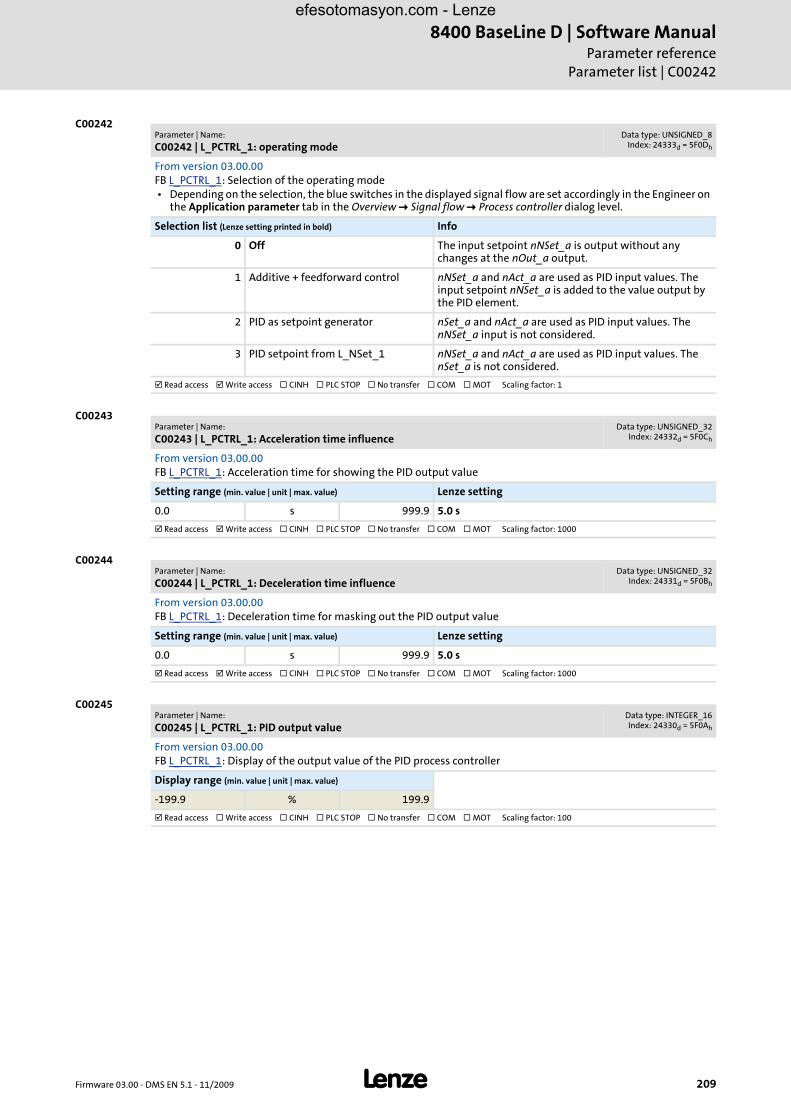
Firmware 03.00 - DMS EN 5.1 - 11/2009 L 209
8400 BaseLine D | Software ManualParameter reference
Parameter list | C00242
C00242
C00243
C00244
C00245
Parameter | Name:
C00242 | L_PCTRL_1: operating modeData type: UNSIGNED_8
Index: 24333d = 5F0Dh
From version 03.00.00FB L_PCTRL_1: Selection of the operating mode • Depending on the selection, the blue switches in the displayed signal flow are set accordingly in the Engineer on
the Application parameter tab in the Overview Signal flow Process controller dialog level.
Selection list (Lenze setting printed in bold) Info
0 Off The input setpoint nNSet_a is output without any changes at the nOut_a output.
1 Additive + feedforward control nNSet_a and nAct_a are used as PID input values. The input setpoint nNSet_a is added to the value output by the PID element.
2 PID as setpoint generator nSet_a and nAct_a are used as PID input values. The nNSet_a input is not considered.
3 PID setpoint from L_NSet_1 nNSet_a and nAct_a are used as PID input values. The nSet_a is not considered.
Read access Write access CINH PLC STOP No transfer COM MOT Scaling factor: 1
Parameter | Name:
C00243 | L_PCTRL_1: Acceleration time influenceData type: UNSIGNED_32
Index: 24332d = 5F0Ch
From version 03.00.00FB L_PCTRL_1: Acceleration time for showing the PID output value
Setting range (min. value | unit | max. value) Lenze setting
0.0 s 999.9 5.0 s
Read access Write access CINH PLC STOP No transfer COM MOT Scaling factor: 1000
Parameter | Name:
C00244 | L_PCTRL_1: Deceleration time influenceData type: UNSIGNED_32
Index: 24331d = 5F0Bh
From version 03.00.00FB L_PCTRL_1: Deceleration time for masking out the PID output value
Setting range (min. value | unit | max. value) Lenze setting
0.0 s 999.9 5.0 s
Read access Write access CINH PLC STOP No transfer COM MOT Scaling factor: 1000
Parameter | Name:
C00245 | L_PCTRL_1: PID output valueData type: INTEGER_16Index: 24330d = 5F0Ah
From version 03.00.00FB L_PCTRL_1: Display of the output value of the PID process controller
Display range (min. value | unit | max. value)
-199.9 % 199.9
Read access Write access CINH PLC STOP No transfer COM MOT Scaling factor: 100
efesotomasyon.com - Lenze
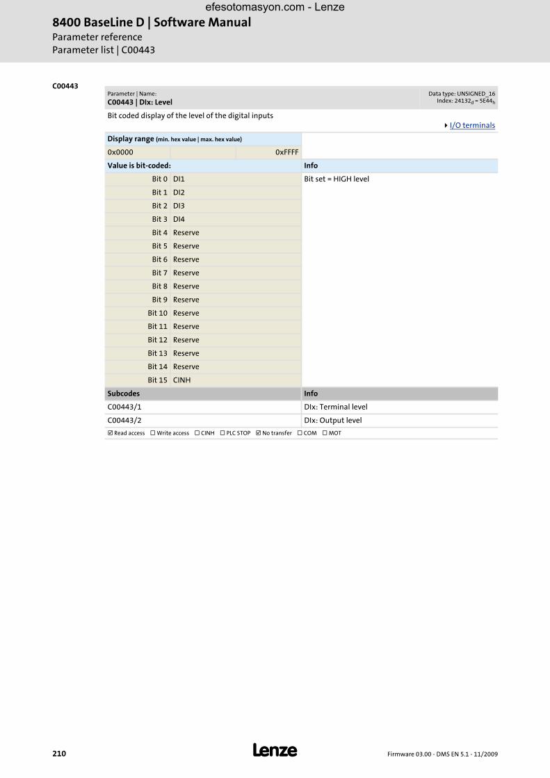
8400 BaseLine D | Software ManualParameter referenceParameter list | C00443
210 L Firmware 03.00 - DMS EN 5.1 - 11/2009
C00443Parameter | Name:
C00443 | DIx: LevelData type: UNSIGNED_16
Index: 24132d = 5E44h
Bit coded display of the level of the digital inputsI/O terminals
Display range (min. hex value | max. hex value)
0x0000 0xFFFF
Value is bit-coded: Info
Bit 0 DI1 Bit set = HIGH level
Bit 1 DI2
Bit 2 DI3
Bit 3 DI4
Bit 4 Reserve
Bit 5 Reserve
Bit 6 Reserve
Bit 7 Reserve
Bit 8 Reserve
Bit 9 Reserve
Bit 10 Reserve
Bit 11 Reserve
Bit 12 Reserve
Bit 13 Reserve
Bit 14 Reserve
Bit 15 CINH
Subcodes Info
C00443/1 DIx: Terminal level
C00443/2 DIx: Output level
Read access Write access CINH PLC STOP No transfer COM MOT
efesotomasyon.com - Lenze

Firmware 03.00 - DMS EN 5.1 - 11/2009 L 211
8400 BaseLine D | Software ManualParameter reference
Parameter list | C00444
C00444
C00470
Parameter | Name:
C00444 | DOx: LevelData type: UNSIGNED_16
Index: 24131d = 5E43h
Bit coded display of the level of the digital outputsI/O terminals
Display range (min. hex value | max. hex value)
0x0000 0xFFFF
Value is bit-coded: Info
Bit 0 Relay Bit set = HIGH level
Bit 1 DO1
Bit 2 Reserved
Bit 3 Reserved
Bit 4 Reserved
Bit 5 Reserved
Bit 6 Reserved
Bit 7 Reserved
Bit 8 Reserved
Bit 9 Reserved
Bit 10 Reserved
Bit 11 Reserved
Bit 12 Reserved
Bit 13 Reserved
Bit 14 Reserved
Bit 15 Reserved
Subcodes Info
C00444/1 DOx: Input level
C00444/2 DOx: Terminal level
Read access Write access CINH PLC STOP No transfer COM MOT
Parameter | Name:
C00470 | LS_ParFree_bData type: UNSIGNED_8
Index: 24105d = 5E29h
SB LS_ParFree_b: Setting of the signal level to be output
Selection list
0 False
1 True
Subcodes Lenze setting Info
C00470/1 0: False Signal level for output bPar1 ... bPar16
C00470/...
C00470/16
Read access Write access CINH PLC STOP No transfer COM MOT Scaling factor: 1
efesotomasyon.com - Lenze

8400 BaseLine D | Software ManualParameter referenceParameter list | C00472
212 L Firmware 03.00 - DMS EN 5.1 - 11/2009
C00472
C00480
C00481
Parameter | Name:
C00472 | LS_ParFree_aData type: INTEGER_16Index: 24103d = 5E27h
SB LS_ParFree_a: Setting of the analog signals to be output
Setting range (min. value | unit | max. value)
-199.9 % 199.9
Subcodes Lenze setting Info
C00472/1 0.0 % Value for output nPar1_a
C00472/2 0.0 % Value for output nPar2_a
C00472/3 100.0 % Value for output nPar3_a
C00472/4 100.0 % Value for output nPar4_a
Read access Write access CINH PLC STOP No transfer COM MOT Scaling factor: 100
Parameter | Name:
C00480 | LS_DisFree_bData type: UNSIGNED_8
Index: 24095d = 5E1Fh
SB LS_DisFree_b: Display of the input values
Display range (min. hex value | max. hex value)
0x00 0xFF
Value is bit-coded: Info
Bit 0 bDis1 Signal level input bDis1 ... bDis8
... ...
Bit 7 bDis8
Read access Write access CINH PLC STOP No transfer COM MOT
Parameter | Name:
C00481 | LS_DisFreeData type: UNSIGNED_16
Index: 24094d = 5E1Eh
SB LS_DisFree: Display of the input values
Display range (min. hex value | max. hex value)
0x0000 0xFFFF
Value is bit-coded:
Bit 0 Bit0
... ...
Bit 15 Bit15
Subcodes Info
C00481/1 Input values wDis1 ... wDis4
C00481/...
C00481/4
Read access Write access CINH PLC STOP No transfer COM MOT
efesotomasyon.com - Lenze
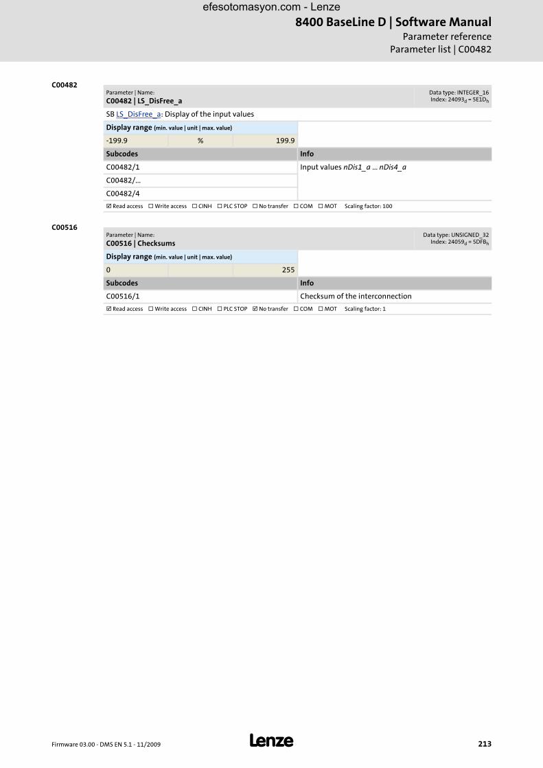
Firmware 03.00 - DMS EN 5.1 - 11/2009 L 213
8400 BaseLine D | Software ManualParameter reference
Parameter list | C00482
C00482
C00516
Parameter | Name:
C00482 | LS_DisFree_aData type: INTEGER_16Index: 24093d = 5E1Dh
SB LS_DisFree_a: Display of the input values
Display range (min. value | unit | max. value)
-199.9 % 199.9
Subcodes Info
C00482/1 Input values nDis1_a ... nDis4_a
C00482/...
C00482/4
Read access Write access CINH PLC STOP No transfer COM MOT Scaling factor: 100
Parameter | Name:
C00516 | ChecksumsData type: UNSIGNED_32
Index: 24059d = 5DFBh
Display range (min. value | unit | max. value)
0 255
Subcodes Info
C00516/1 Checksum of the interconnection
Read access Write access CINH PLC STOP No transfer COM MOT Scaling factor: 1
efesotomasyon.com - Lenze

8400 BaseLine D | Software ManualParameter referenceParameter list | C00517
214 L Firmware 03.00 - DMS EN 5.1 - 11/2009
C00517
C00565
C00574
Parameter | Name:
C00517 | User menuData type: INTEGER_32Index: 24058d = 5DFAh
When a system is installed, parameters must be changed time and again until the system runs satisfactorily. The user menu of a device serves to create a selection of frequently used parameters to be able to access and change these parameters quickly.
Setting range (min. value | unit | max. value)
0 994
Subcodes Lenze setting Info
C00517/1 51 C00051: Display of actual speed value
C00517/2 53 C00053: Display of DC-bus voltage
C00517/3 54 C00054: Display of motor current
C00517/4 61 C00061: Display of heatsink temperature
C00517/5 137 C00137: Display of device state
C00517/6 0
C00517/7 0
C00517/8 11 C00011: Reference speed
C00517/9 39 C00039: Fixed setpoints 1 ... 3
C00517/10 0
C00517/11 12 C00012: Accel. time - main setpoint
C00517/12 13 C00013: Decel. time - main setpoint
C00517/13 15 C00015: V/f base frequency
C00517/14 16 C00016: Vmin boost
C00517/15 22 C00022: Imax in motor mode
C00517/16 120 C00120: Motor overload threshold (I2xt)
C00517/17 87 C00087: Rated motor speed
C00517/18 99 C00099: Display of firmware version
C00517/19 0
C00517/20 0
Read access Write access CINH PLC STOP No transfer COM MOT Scaling factor: 1
Parameter | Name:
C00565 | Resp. to mains phase failureData type: UNSIGNED_8
Index: 24010d = 5DCAh
Response to the failure of mains phases
Selection list (Lenze setting printed in bold)
0 No Reaction
1 Fault
4 WarningLocked
Read access Write access CINH PLC STOP No transfer COM MOT Scaling factor: 1
Parameter | Name:
C00574 | Resp. to brake resist. overtemp.Data type: UNSIGNED_8
Index: 24001d = 5DC1h
Response to overtemperature of the brake resistor
Selection list (Lenze setting printed in bold)
0 No Reaction
1 Fault
4 WarningLocked
Read access Write access CINH PLC STOP No transfer COM MOT Scaling factor: 1
efesotomasyon.com - Lenze

Firmware 03.00 - DMS EN 5.1 - 11/2009 L 215
8400 BaseLine D | Software ManualParameter reference
Parameter list | C00581
C00581
C00598
C00600
C00601
Parameter | Name:
C00581 | Resp. LS_SetError_xData type: UNSIGNED_8
Index: 23994d = 5DBAh
SB LS_SetError_1: Selection of the error responses for application error messages • An application error message is tripped by a FALSE-TRUE edge at the binary inputs bSetError1...2.
Selection list
0 No Reaction
1 Fault
2 Trouble
4 WarningLocked
Subcodes Lenze setting Info
C00581/1 1: Fault Resp. LS_SetError_1 bSetError1
C00581/2 1: Fault Resp. LS_SetError_1 bSetError2
Read access Write access CINH PLC STOP No transfer COM MOT Scaling factor: 1
Parameter | Name:
C00598 | Resp. to open circuit AINxData type: UNSIGNED_8
Index: 23977d = 5DA9h
Configuration of monitoring of the analog input
Selection list
0 No Reaction
1 Fault
2 Trouble
4 WarningLocked
Subcodes Lenze setting Info
C00598/1 1: Fault Response to open circuit at AIN1 when being configured as 4 ... 20 mA current loop
Read access Write access CINH PLC STOP No transfer COM MOT Scaling factor: 1
Parameter | Name:
C00600 | Resp. to DC bus overvoltageData type: UNSIGNED_8
Index: 23975d = 5DA7h
Configuration of monitoring of the motor control (group 3)
Selection list
1 Fault
2 Trouble
Subcodes Lenze setting Info
C00600/1 2: Trouble Resp. to undervoltage in the DC bus
Read access Write access CINH PLC STOP No transfer COM MOT Scaling factor: 1
Parameter | Name:
C00601 | Del. resp.to fault: DC bus overvoltageData type: UNSIGNED_16
Index: 23974d = 5DA6h
Delay times for error responses
Setting range (min. value | unit | max. value)
0.00 s 65.00
Subcodes Lenze setting Info
C00601/1 2.00 s Delay time for error activation "DC-bus overvoltage" • In case of DC-bus overvoltage, an error is only
transmitted after this delay time has elapsed.
Read access Write access CINH PLC STOP No transfer COM MOT Scaling factor: 1000
efesotomasyon.com - Lenze

8400 BaseLine D | Software ManualParameter referenceParameter list | C00604
216 L Firmware 03.00 - DMS EN 5.1 - 11/2009
C00604
C00606
C00620
Parameter | Name:
C00604 | Resp. to device overload (Ixt)Data type: UNSIGNED_8
Index: 23971d = 5DA3h
Response if the adjustable device utilisation threshold (C00123) is reached. • The current device utilisation is displayed in C00064.
Selection list (Lenze setting printed in bold)
0 No Reaction
1 Fault
4 WarningLocked
Read access Write access CINH PLC STOP No transfer COM MOT Scaling factor: 1
Parameter | Name:
C00606 | Resp. to motor overload (I²xt)Data type: UNSIGNED_8
Index: 23969d = 5DA1h
Response if the adjustable motor overload threshold (C00120) is reached. • The current thermal motor load is displayed in C00066.
Selection list (Lenze setting printed in bold)
0 No Reaction
1 Fault
4 WarningLocked
Read access Write access CINH PLC STOP No transfer COM MOT Scaling factor: 1
Parameter | Name:
C00620 | 16-bit system connectionData type: UNSIGNED_16
Index: 23955d = 5D93h
Connection parameters: 16-bit inputs • Selection of the 16-bit output signals for connection with the 16-bit input signals. • The selection list contains all 16-bit output signals which can be assigned to the 16-bit inputs mapped by the
subcodes.
Selection list Info
0 Not connected
1 C_nPos100_a(100.0%)
2 C_nNeg100_a(-100.0%)
3 C_nPos199_9_a(199.9%)
4 C_nNeg199_9_a(-199.9%)
5 C_w65535
6 C_wDriveCtrl
10 AIn1_Out
20 nPar1_a
21 nPar2_a
22 nPar3_a
23 nPar4_a
24 LS_Keypad_nTorqueMotLim_a
25 LS_Keypad_nTorqueGenLim_a
26 LS_Keypad_nMainSetValue_a
50 LA_NCTRL_nMotorFreqAct_a
51 LA_NCTRL_nOutputSpeedCtrl_a
52 LA_NCtrl_nMotorSpeedAct_a
53 LA_NCtrl_nMotor Voltage_a
54 LA_NCtrl_nDCVoltage_a
55 LA_NCtrl_nMotorCurrent_a
efesotomasyon.com - Lenze

Firmware 03.00 - DMS EN 5.1 - 11/2009 L 217
8400 BaseLine D | Software ManualParameter reference
Parameter list | C00621
C00621
56 LA_NCtrl_nMotorTorqueAct_a
57 LA_NCTRL_nHeatsinkTemperature_a
70 LA_NCTRL_wDeviceStateWord
71 LA_NCTRL_wDeviceAuxStateWord
72 LA_NCTRL_wDetermFailNoLow
73 LA_NCTRL_wDetermFailNoHigh
Subcodes Lenze setting Info
C00620/1 0: Not connected Reserved
C00620/2 0: Not connected Reserved
C00620/3 0: Not connected Reserved
C00620/4 0: Not connected Reserved
C00620/5 0: Not connected LS_DisFree: wDis1
C00620/6 0: Not connected LS_DisFree: wDis2
C00620/7 0: Not connected LS_DisFree: wDis3
C00620/8 0: Not connected LS_DisFree: wDis4
C00620/9 0: Not connected LS_DisFree_a: nDis1_a
C00620/10 0: Not connected LS_DisFree_a: nDis2_a
C00620/11 0: Not connected LS_DisFree_a: nDis3_a
C00620/12 0: Not connected LS_DisFree_a: nDis4_a
Read access Write access CINH PLC STOP No transfer COM MOT Scaling factor: 1
Parameter | Name:
C00620 | 16-bit system connectionData type: UNSIGNED_16
Index: 23955d = 5D93h
Parameter | Name:
C00621 | Bool system connectionData type: UNSIGNED_16
Index: 23954d = 5D92h
Connection parameters: Binary inputs • Selection of the binary output signals for connection with the binary input signals. • The selection list contains all binary output signals which can be assigned to the binary inputs mapped by the
subcodes.
Selection list Info
0 Not connected
1 C_bTrue
11 DigIn_bIn1
12 DigIn_bIn2
13 DigIn_bIn3
14 DigIn_bIn4
15 DigIn_CInh
20 bPar1
21 bPar2
22 bPar3
23 bPar4
24 bPar5
25 bPar6
26 bPar7
27 bPar8
28 bPar9
efesotomasyon.com - Lenze
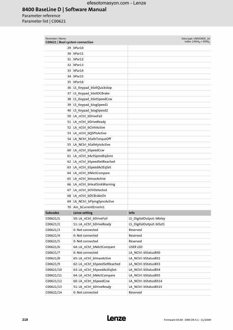
8400 BaseLine D | Software ManualParameter referenceParameter list | C00621
218 L Firmware 03.00 - DMS EN 5.1 - 11/2009
29 bPar10
30 bPar11
31 bPar12
32 bPar13
33 bPar14
34 bPar15
35 bPar16
36 LS_Keypad_bSetQuickstop
37 LS_Keypad_bSetDCBrake
38 LS_Keypad_bSetSpeedCcw
39 LS_Keypad_bJogSpeed1
40 LS_Keypad_bJogSpeed2
50 LA_nCtrl_bDriveFail
51 LA_nCtrl_bDriveReady
52 LA_nCtrl_bCInhActive
53 LA_nCtrl_bQSPIsActive
54 LA_NCtrl_bSafeTorqueOff
55 LA_NCtrl_bSafetyIsActive
60 LA_nCtrl_bSpeedCcw
61 LA_nCtrl_bActSpeedEqZero
62 LA_nCtrl_bSpeedSetReached
63 LA_nCtrl_bSpeedActEqSet
64 LA_nCtrl_bNActCompare
65 LA_nCtrl_bImaxActive
66 LA_nCtrl_bHeatSinkWarning
67 LA_nCtrl_bOVDetected
68 LA_nCtrl_bDCBrakeOn
69 LA_NCtrl_bFlyingSyncActive
70 Ain_bCurrentErrorIn1
Subcodes Lenze setting Info
C00621/1 50: LA_nCtrl_bDriveFail LS_DigitalOutput: bRelay
C00621/2 51: LA_nCtrl_bDriveReady LS_DigitalOutput: bOut1
C00621/3 0: Not connected Reserved
C00621/4 0: Not connected Reserved
C00621/5 0: Not connected Reserved
C00621/6 64: LA_nCtrl_bNActCompare USER LED
C00621/7 0: Not connected LA_NCtrl: bStatusBit0
C00621/8 65: LA_nCtrl_bImaxActive LA_NCtrl: bStatusBit2
C00621/9 62: LA_nCtrl_bSpeedSetReached LA_NCtrl: bStatusBit3
C00621/10 63: LA_nCtrl_bSpeedActEqSet LA_NCtrl: bStatusBit4
C00621/11 64: LA_nCtrl_bNActCompare LA_NCtrl: bStatusBit5
C00621/12 60: LA_nCtrl_bSpeedCcw LA_NCtrl: bStatusBit14
C00621/13 51: LA_nCtrl_bDriveReady LA_NCtrl: bStatusBit15
C00621/14 0: Not connected Reserved
Parameter | Name:
C00621 | Bool system connectionData type: UNSIGNED_16
Index: 23954d = 5D92h
efesotomasyon.com - Lenze

Firmware 03.00 - DMS EN 5.1 - 11/2009 L 219
8400 BaseLine D | Software ManualParameter reference
Parameter list | C00700
C00700
C00621/15 0: Not connected Reserved
C00621/16 0: Not connected Ls_DisFree_b: bDis1
C00621/17 0: Not connected Ls_DisFree_b: bDis2
C00621/18 0: Not connected Ls_DisFree_b: bDis3
C00621/19 0: Not connected Ls_DisFree_b: bDis4
C00621/20 0: Not connected Ls_DisFree_b: bDis5
C00621/21 0: Not connected Ls_DisFree_b: bDis6
C00621/22 0: Not connected Ls_DisFree_b: bDis7
C00621/23 0: Not connected Ls_DisFree_b: bDis8
Read access Write access CINH PLC STOP No transfer COM MOT Scaling factor: 1
Parameter | Name:
C00621 | Bool system connectionData type: UNSIGNED_16
Index: 23954d = 5D92h
Parameter | Name:
C00700 | LA_NCtrl: analog connection listData type: UNSIGNED_16
Index: 23875d = 5D43h
Connection parameters for "Actuating drive - speed" application: 16-bit inputs • Selection of the 16-bit output signals for connection with the 16-bit input signals • The selection list contains all 16-bit output signals which can be assigned to the 16-bit inputs mapped by the
subcodes.
Selection list Info
0 Not connected
1 C_nPos100_a(100.0%)
2 C_nNeg100_a(-100.0%)
3 C_nPos199_9_a(199.9%)
4 C_nNeg199_9_a(-199.9%)
5 C_w65535
6 C_wDriveCtrl
10 AIn1_Out
20 nPar1_a
21 nPar2_a
22 nPar3_a
23 nPar4_a
24 LS_Keypad_nTorqueMotLim_a
25 LS_Keypad_nTorqueGenLim_a
26 LS_Keypad_nMainSetValue_a
50 LA_NCTRL_nMotorFreqAct_a
51 LA_NCTRL_nOutputSpeedCtrl_a
52 LA_NCtrl_nMotorSpeedAct_a
53 LA_NCtrl_nMotor Voltage_a
54 LA_NCtrl_nDCVoltage_a
55 LA_NCtrl_nMotorCurrent_a
56 LA_NCtrl_nMotorTorqueAct_a
57 LA_NCTRL_nHeatsinkTemperature_a
70 LA_NCTRL_wDeviceStateWord
71 LA_NCTRL_wDeviceAuxStateWord
72 LA_NCTRL_wDetermFailNoLow
efesotomasyon.com - Lenze

8400 BaseLine D | Software ManualParameter referenceParameter list | C00701
220 L Firmware 03.00 - DMS EN 5.1 - 11/2009
C00701
73 LA_NCTRL_wDetermFailNoHigh
Subcodes Lenze setting Info
C00700/1 10: AIn1_Out LA_NCtrl: nMainSetValue_a
C00700/2 22: nPar3_a LA_NCtrl: nTorqueMotLim_a
C00700/3 22: nPar3_a LA_NCtrl: nTorqueGenLim_a
C00700/4 0: Not connected Reserved
C00700/5 0: Not connected Reserved
C00700/6 1: C_nPos100_a(100.0%) LA_NCtrl: nPIDVpAdapt_a
C00700/7 0: Not connected LA_NCtrl: nPIDActValue_a
C00700/8 1: C_nPos100_a(100.0%) LA_NCtrl: nPIDInfluence_a
C00700/9 0: Not connected LA_NCtrl: nPIDsetValue_a
Read access Write access CINH PLC STOP No transfer COM MOT Scaling factor: 1
Parameter | Name:
C00700 | LA_NCtrl: analog connection listData type: UNSIGNED_16
Index: 23875d = 5D43h
Parameter | Name:
C00701 | LA_NCtrl: digital connection listData type: UNSIGNED_16
Index: 23874d = 5D42h
Connection parameters for "Actuating drive - speed" application: Binary inputs • Selection of the binary output signals for connection with the binary input signals • The selection list contains all binary output signals which can be assigned to the binary inputs mapped by the
subcodes.
Selection list Info
0 Not connected
1 C_bTrue
11 DigIn_bIn1
12 DigIn_bIn2
13 DigIn_bIn3
14 DigIn_bIn4
15 DigIn_CInh
20 bPar1
21 bPar2
22 bPar3
23 bPar4
24 bPar5
25 bPar6
26 bPar7
27 bPar8
28 bPar9
29 bPar10
30 bPar11
31 bPar12
32 bPar13
33 bPar14
34 bPar15
35 bPar16
36 LS_Keypad_bSetQuickstop
37 LS_Keypad_bSetDCBrake
efesotomasyon.com - Lenze

Firmware 03.00 - DMS EN 5.1 - 11/2009 L 221
8400 BaseLine D | Software ManualParameter reference
Parameter list | C00701
38 LS_Keypad_bSetSpeedCcw
39 LS_Keypad_bJogSpeed1
40 LS_Keypad_bJogSpeed2
50 LA_nCtrl_bDriveFail
51 LA_nCtrl_bDriveReady
52 LA_nCtrl_bCInhActive
53 LA_nCtrl_bQSPIsActive
54 LA_NCtrl_bSafeTorqueOff
55 LA_NCtrl_bSafetyIsActive
60 LA_nCtrl_bSpeedCcw
61 LA_nCtrl_bActSpeedEqZero
62 LA_nCtrl_bSpeedSetReached
63 LA_nCtrl_bSpeedActEqSet
64 LA_nCtrl_bNActCompare
65 LA_nCtrl_bImaxActive
66 LA_nCtrl_bHeatSinkWarning
67 LA_nCtrl_bOVDetected
68 LA_nCtrl_bDCBrakeOn
69 LA_NCtrl_bFlyingSyncActive
70 Ain_bCurrentErrorIn1
Subcodes Lenze setting Info
C00701/1 0: Not connected LA_NCtrl: bCInh
C00701/2 15: DigIn_CInh LA_NCtrl: bFailReset
C00701/3 0: Not connected LA_NCtrl: bSetQuickstop
C00701/4 13: DigIn_bIn3 LA_NCtrl: bSetDCBrake
C00701/5 14: DigIn_bIn4 LA_NCtrl: bSetSpeedCcw
C00701/6 11: DigIn_bIn1 LA_NCtrl: bJogSpeed1
C00701/7 12: DigIn_bIn2 LA_NCtrl: bJogSpeed2
C00701/8 0: Not connected LA_NCtrl: bMPotUp
C00701/9 0: Not connected LA_NCtrl: bMPotDown
C00701/10 0: Not connected LA_NCtrl: bMPotInAct
C00701/11 0: Not connected LA_NCtrl: bMPotEnable
C00701/12 0: Not connected LA_NCtrl: bRFG_0
C00701/13 0: Not connected LA_NCtrl: bSetError1
C00701/14 0: Not connected LA_NCtrl: bSetError2
C00701/15 1: C_bTrue LA_NCtrl: bPIDInfluenceRamp
C00701/16 0: Not connected LA_NCtrl: bPIDIOff
C00701/17 1: C_bTrue LA_NCtrl: bRLQCw
C00701/18 0: Not connected LA_NCtrl: bRLQCcw
Read access Write access CINH PLC STOP No transfer COM MOT Scaling factor: 1
Parameter | Name:
C00701 | LA_NCtrl: digital connection listData type: UNSIGNED_16
Index: 23874d = 5D42h
efesotomasyon.com - Lenze

8400 BaseLine D | Software ManualParameter referenceParameter list | C00725
222 L Firmware 03.00 - DMS EN 5.1 - 11/2009
C00725
C00727
C00728
C00800
Parameter | Name:
C00725 | Current switching frequencyData type: UNSIGNED_8
Index: 23850d = 5D2Ah
From version 03.00.00Display of the current switching frequency • When a variable switching frequency is selected in C00018, the switching frequency may change as a function
of the load and rotational frequency.
Selection list (read only)
1 4 kHz var./drive-optimised
2 8 kHz var./drive-optimised
3 16 kHz var./drive-optimised
5 2 kHz constant/drive-optimised
6 4 kHz constant/drive-optimised
7 8 kHz constant/drive-optimised
8 16 kHz constant/drive-optimised
Read access Write access CINH PLC STOP No transfer COM MOT Scaling factor: 1
Parameter | Name:
C00727 | LS_Keypad: Digital valuesData type: UNSIGNED_8
Index: 23848d = 5D28h
Executing control commands when operating via keypad
Setting range (min. value | unit | max. value)
0 1
Subcodes Lenze setting Info
C00727/1 0 "1" ≡ request quick stop
C00727/2 0 "1" ≡ request DC-injection braking
C00727/3 0 "1" ≡ request reversal
C00727/4 0 "1" ≡ request fixed speed setpoint 1
C00727/5 0 "1" ≡ request fixed speed setpoint 2
Read access Write access CINH PLC STOP No transfer COM MOT Scaling factor: 1
Parameter | Name:
C00728 | LS_Keypad: Keypad analog valuesData type: INTEGER_16Index: 23847d = 5D27h
Selection of different setpoints when operating via keypad
Setting range (min. value | unit | max. value)
-199.9 % 199.9
Subcodes Lenze setting Info
C00728/1 100.0 % Torque limit in motor mode
C00728/2 100.0 % Torque limit in generator mode
C00728/3 0.0 % Setpoint speed
Read access Write access CINH PLC STOP No transfer COM MOT Scaling factor: 100
Parameter | Name:
C00800 | L_MPot_1: Upper limitData type: INTEGER_16Index: 23775d = 5CDFh
FB L_MPot_1: Upper limit of the motor potentiometer function
Setting range (min. value | unit | max. value) Lenze setting
-199.9 % 199.9 100.0 %
Read access Write access CINH PLC STOP No transfer COM MOT Scaling factor: 100
efesotomasyon.com - Lenze

Firmware 03.00 - DMS EN 5.1 - 11/2009 L 223
8400 BaseLine D | Software ManualParameter reference
Parameter list | C00801
C00801
C00802
C00803
C00804
C00805
Parameter | Name:
C00801 | L_MPot_1: Lower limitData type: INTEGER_16Index: 23774d = 5CDEh
FB L_MPot_1: Lower limit of the motor potentiometer function
Setting range (min. value | unit | max. value) Lenze setting
-199.9 % 199.9 -100.0 %
Read access Write access CINH PLC STOP No transfer COM MOT Scaling factor: 100
Parameter | Name:
C00802 | L_MPot_1: Acceleration timeData type: UNSIGNED_16
Index: 23773d = 5CDDh
FB L_MPot_1: Acceleration time of the motor potentiometer function
Setting range (min. value | unit | max. value) Lenze setting
0.1 s 999.9 10.0 s
Read access Write access CINH PLC STOP No transfer COM MOT Scaling factor: 10
Parameter | Name:
C00803 | L_MPot_1: Deceleration timeData type: UNSIGNED_16
Index: 23772d = 5CDCh
FB L_MPot_1: Deceleration time of the motor potentiometer function
Setting range (min. value | unit | max. value) Lenze setting
0.1 s 999.9 10.0 s
Read access Write access CINH PLC STOP No transfer COM MOT Scaling factor: 10
Parameter | Name:
C00804 | L_MPot_1: Inactive functionData type: UNSIGNED_8
Index: 23771d = 5CDBh
FB L_MPot_1: Selection of the response when deactivating the motor potentiometer via the bInAct input
Selection list (Lenze setting printed in bold) Info
0 Keep value Keep output value
1 Deceleration to 0 Deceleration via ramp to 0
2 Deceleration to lower limit Deceleration via ramp via the lower limit (C00801)
3 Without ramp to 0 Jump to 0
4 Without ramp to lower limit Jump to lower limit (C00800)
5 Acceleration to upper limit Acceleration via ramp to upper limit (C00800)
Read access Write access CINH PLC STOP No transfer COM MOT Scaling factor: 1
Parameter | Name:
C00805 | L_MPot_1: Init fct.Data type: UNSIGNED_8
Index: 23770d = 5CDAh
FB L_MPot_1: Selection of the response when switching on the device
Selection list (Lenze setting printed in bold)
0 Load last value
1 U. Load limit
2 Load 0
Read access Write access CINH PLC STOP No transfer COM MOT Scaling factor: 1
efesotomasyon.com - Lenze

8400 BaseLine D | Software ManualParameter referenceParameter list | C00806
224 L Firmware 03.00 - DMS EN 5.1 - 11/2009
C00806
C00830
C00831
Parameter | Name:
C00806 | L_MPot_1: UseData type: UNSIGNED_8
Index: 23769d = 5CD9h
FB L_MPot_1: Application of motor potentiometer
Selection list (Lenze setting printed in bold) Info
0 No The motor potentiometer is not used. • The analog value applied to the nIn_a input is looped
through without any changes to the nOut_a output.
1 Yes The motor potentiometer is used. • The analog value applied to the nIn_a input is led via
the motor potentiometer and provided at the nOut_a output.
Read access Write access CINH PLC STOP No transfer COM MOT Scaling factor: 1
Parameter | Name:
C00830 | 16Bit-Input analogData type: INTEGER_16Index: 23745d = 5CC1h
Display in percent of 16-bit input values of different blocks
Display range (min. value | unit | max. value)
-199.9 % 199.9
Subcodes Info
C00830/1 L_NSet_1: nNSet_a
C00830/2 L_NSet: nOut_a
C00830/3 LS_MCTRL: nSpeedSetValue_a
C00830/4 LS_MCTRL: nTorqueMotLimit_a
C00830/5 LS_MCTRL: nTorqueGenLimit_a
C00830/6 L_PCTRL_1: nAct_a
C00830/7 L_PCTRL_1: nAdapt_a
C00830/8 L_PCTRL_1: nSet_a
C00830/9 L_PCTRL_1: nInflu_a
C00830/10 L_PCTRL_1: nNSet_a
C00830/11 L_MPot_1: nIn_a
Read access Write access CINH PLC STOP No transfer COM MOT Scaling factor: 100
Parameter | Name:
C00831 | 16Bit-Input commonData type: UNSIGNED_16
Index: 23744d = 5CC0h
From version 03.00.00Decimal/hexadecimal/bit-coded display of 16-bit input values of different blocks
Display range (min. hex value | max. hex value)
0x0000 0xFFFF
Value is bit-coded:
Bit 0 Bit0
... ...
Bit 15 Bit15
Subcodes Info
C00831/1 LS_DCTRL: wCANControl
Read access Write access CINH PLC STOP No transfer COM MOT
efesotomasyon.com - Lenze

Firmware 03.00 - DMS EN 5.1 - 11/2009 L 225
8400 BaseLine D | Software ManualParameter reference
Parameter list | C00833
C00833
C00909
Parameter | Name:
C00833 | 8Bit-InputData type: UNSIGNED_8
Index: 23742d = 5CBEh
From version 03.00.00Display of the signal status of the binary inputs of different blocks
Selection list
0 False
1 True
Subcodes Info
C00833/1 L_NSet_1: bRfg0
C00833/2 L_NSet_1: bNSetInv
C00833/3 L_NSet_1: bJog1
C00833/4 L_NSet_1: bJog2
C00833/5 LS_SetError_1: bSetError1
C00833/6 LS_SetError_1: bSetError2
C00833/7 L_MPot_1: bUp
C00833/8 L_MPot_1: bInAct
C00833/9 L_MPot_1: bDown
C00833/10 L_MPot_1: bEnable
C00833/11 Reserved
C00833/12 L_PCTRL_1: bIOff
C00833/13 L_PCTRL_1: bEnableInfluenceRamp
C00833/14 LS_DCTRL: bCINH
C00833/15 LS_DCTRL: bFailReset
C00833/16 LS_DCTRL: bStatus_B0
C00833/17 LS_DCTRL: bStatus_B2
C00833/18 LS_DCTRL: bStatus_B3
C00833/19 LS_DCTRL: bStatus_B4
C00833/20 LS_DCTRL: bStatus_B5
C00833/21 LS_DCTRL: bStatus_B14
C00833/22 LS_DCTRL: bStatus_B15
C00833/23 L_RLQ_1: bCw
C00833/24 L_RLQ_1: bCcw
Read access Write access CINH PLC STOP No transfer COM MOT Scaling factor: 1
Parameter | Name:
C00909 | Speed limitationData type: INTEGER_16Index: 23666d = 5C72h
Maximum positive/negative speed for all operating modes
Setting range (min. value | unit | max. value)
0.0 % 175.0
Subcodes Lenze setting Info
C00909/1 120.0 % Max. pos. speed
C00909/2 120.0 % Max. neg. speed
Read access Write access CINH PLC STOP No transfer COM MOT Scaling factor: 100
efesotomasyon.com - Lenze

8400 BaseLine D | Software ManualParameter referenceParameter list | C00910
226 L Firmware 03.00 - DMS EN 5.1 - 11/2009
C00910
C00990
C00991
C00992
C00994
Parameter | Name:
C00910 | Frequency limitationData type: UNSIGNED_16
Index: 23665d = 5C71h
Maximum positive/negative output frequency for all operating modes
Setting range (min. value | unit | max. value)
0 Hz 300
Subcodes Lenze setting Info
C00910/1 300 Hz Max. pos. output frequency
C00910/2 300 Hz Max. neg. output frequency
Read access Write access CINH PLC STOP No transfer COM MOT Scaling factor: 1
Parameter | Name:
C00990 | Flying restart fct.: ActivationData type: UNSIGNED_8
Index: 23585d = 5C21h
Switch on/activate flying restart circuit for non-feedback drive systems
Selection list (Lenze setting printed in bold)
0 Off
1 On
Read access Write access CINH PLC STOP No transfer COM MOT Scaling factor: 1
Parameter | Name:
C00991 | Flying restart fct.: ProcessData type: UNSIGNED_16
Index: 23584d = 5C20h
Selection of the starting value and the speed search range for the flying restart function
Selection list (Lenze setting printed in bold)
5 -n...+n | Last output frequency
6 -n...+n | Actual setpoint frequency
Read access Write access CINH PLC STOP No transfer COM MOT Scaling factor: 1
Parameter | Name:
C00992 | Flying restart: start frequencyData type: INTEGER_16Index: 23583d = 5C1Fh
Selection of the starting value for the flying restart function
Setting range (min. value | unit | max. value) Lenze setting
-200 Hz 200 10 Hz
Read access Write access CINH PLC STOP No transfer COM MOT Scaling factor: 1
Parameter | Name:
C00994 | Flying restart fct.: CurrentData type: INTEGER_16Index: 23581d = 5C1Dh
Current to be injected during the flying restart process • 100 % ≡ rated motor current (C00081). • The flying restart current is to amount to 10 ... 25 % of the rated motor current.
Setting range (min. value | unit | max. value) Lenze setting
0.0 % 100.0 25.0 %
Read access Write access CINH PLC STOP No transfer COM MOT Scaling factor: 100
efesotomasyon.com - Lenze

Firmware 03.00 - DMS EN 5.1 - 11/2009 L 227
8400 BaseLine D | Software ManualParameter reference
Table of attributes | C00994
10.3 Table of attributes
The table of attributes contains information required for a communication with thecontroller via parameters.
How to read the table of attributes:
Column Meaning Entry
Code Parameter designation Cxxxxx
Name Parameter short text (display text) Text
Index dec Index under which the parameter is addressed.The subindex for array variables corresponds to the Lenze subcode number.
24575 - Lenze code Is only required for access via a bus system.
hex 5FFFh - Lenze code number
Data DS Data structure E Single variable (only one parameter element)
A Array variable(several parameter elements)
DA Number of array elements (subcodes) Number
DT Data type BITFIELD_8 1 byte bit-coded
BITFIELD_16 2 byte bit-coded
BITFIELD_32 4 byte bit-coded
INTEGER_8 1 byte with sign
INTEGER_16 2 byte with sign
INTEGER_32 4 byte with sign
UNSIGNED_8 1 byte without sign
UNSIGNED_16 2 byte without sign
UNSIGNED_32 4 byte without sign
VISIBLE_STRING ASCII string
Factor Factor for data transmission via a bus system, depending on the number of decimal positions
Factor 1 ≡ no decimal positions10 ≡ 1 decimal position100 ≡ 2 decimal positions1000 ≡ 3 decimal positions
Access R Read access Reading permitted
W Write access Writing permitted
CINH Controller inhibit required Writing is only possible if controller inhibit is set
Code Name Index Data Access
dec hex DS DA DT Factor R W CINH
C00002 Controller commands 24573 5FFD A 32 UNSIGNED_8 1
C00003 Status of last device command 24572 5FFC E 1 UNSIGNED_8 1
C00006 Select motor control 24569 5FF9 E 1 UNSIGNED_8 1
C00007 Select control mode 24568 5FF8 E 1 UNSIGNED_16 1
C00010 Minimum analog setpoint 24565 5FF5 A 1 INTEGER_16 100
C00011 Appl.: Reference speed 24564 5FF4 E 1 UNSIGNED_16 1
C00012 Accel. time - main setpoint 24563 5FF3 E 1 UNSIGNED_32 1000
C00013 Decel. time - main setpoint 24562 5FF2 E 1 UNSIGNED_32 1000
C00015 VFC: V/f base frequency 24560 5FF0 E 1 UNSIGNED_16 10
C00016 VFC: Vmin boost 24559 5FEF E 1 UNSIGNED_16 100
C00018 Switching frequency 24557 5FED E 1 UNSIGNED_8 1
C00019 Auto-DCB: Threshold 24556 5FEC E 1 UNSIGNED_16 1
C00021 Slip comp. 24554 5FEA E 1 INTEGER_16 100
C00022 Imax in motor mode 24553 5FE9 E 1 UNSIGNED_16 100
C00023 Imax in generator mode 24552 5FE8 E 1 INTEGER_16 100
C00024 Comparison value N_Act 24551 5FE7 E 1 INTEGER_16 100
C00026 AINx: Offset 24549 5FE5 A 1 INTEGER_16 100
efesotomasyon.com - Lenze

8400 BaseLine D | Software ManualParameter referenceTable of attributes | C00994
228 L Firmware 03.00 - DMS EN 5.1 - 11/2009
C00027 AINx: Gain 24548 5FE4 A 1 INTEGER_32 100
C00028 AINx: Input voltage 24547 5FE3 A 1 INTEGER_16 100
C00029 AINx: Input current 24546 5FE2 A 1 INTEGER_16 100
C00033 AINx: Output value 24542 5FDE A 1 INTEGER_16 100
C00034 AINx: Configuration 24541 5FDD A 1 UNSIGNED_8 1
C00036 DCB: Current 24539 5FDB E 1 INTEGER_16 100
C00039 Fixed setpoint x (L_NSet_1 n-Fix) 24536 5FD8 A 3 INTEGER_16 100
C00050 MCTRL: Speed setpoint 24525 5FCD E 1 INTEGER_32 1
C00051 MCTRL: Actual speed value 24524 5FCC E 1 INTEGER_32 1
C00052 Motor voltage 24523 5FCB E 1 UNSIGNED_16 1
C00053 DC-bus voltage 24522 5FCA E 1 UNSIGNED_16 1
C00054 Motor current 24521 5FC9 E 1 UNSIGNED_16 100
C00056 Torque 24519 5FC7 A 2 INTEGER_32 100
C00057 Maximum torque 24518 5FC6 E 1 UNSIGNED_32 100
C00058 Output frequency 24517 5FC5 E 1 INTEGER_32 100
C00059 Appl.: Reference frequency C11 24516 5FC4 E 1 UNSIGNED_32 100
C00061 Heatsink temperature 24514 5FC2 E 1 INTEGER_16 1
C00064 Device utilisation (Ixt) 24511 5FBF A 3 INTEGER_16 100
C00066 Thermal motor load (I²xt) 24509 5FBD E 1 INTEGER_16 100
C00073 Vp Imax controller 24502 5FB6 E 1 UNSIGNED_16 100
C00074 Ti Imax controller 24501 5FB5 E 1 UNSIGNED_16 1
C00081 Rated motor power 24494 5FAE E 1 UNSIGNED_16 100
C00084 Motor stator resistance 24491 5FAB E 1 UNSIGNED_32 1
C00085 Motor stator leakage inductance 24490 5FAA E 1 UNSIGNED_16 100
C00087 Rated motor speed 24488 5FA8 E 1 UNSIGNED_16 1
C00088 Rated motor current 24487 5FA7 E 1 UNSIGNED_16 100
C00089 Rated motor frequency 24486 5FA6 E 1 UNSIGNED_16 1
C00090 Rated motor voltage 24485 5FA5 E 1 UNSIGNED_16 1
C00091 Motor cosine phi 24484 5FA4 E 1 UNSIGNED_8 100
C00092 Motor magnetizing inductance 24483 5FA3 E 1 UNSIGNED_16 10
C00093 Power section ID 24482 5FA2 E 1 UNSIGNED_16 1
C00094 Password 24481 5FA1 E 1 INTEGER_32 1
C00095 Motor magnetising current 24480 5FA0 E 1 UNSIGNED_16 100
C00097 Rated motor torque 24478 5F9E E 1 UNSIGNED_32 100
C00098 Rated device current 24477 5F9D E 1 UNSIGNED_16 10
C00099 Firmware version 24476 5F9C E 1 VISIBLE_STRING
C00100 Firmware version 24475 5F9B A 4 UNSIGNED_8 1
C00105 Deceleration time - quick stop 24470 5F96 E 1 UNSIGNED_32 1000
C00106 Auto-DCB: hold time 24469 5F95 E 1 UNSIGNED_32 1000
C00107 DCB: hold time 24468 5F94 E 1 UNSIGNED_32 1000
C00114 DIx inversion 24461 5F8D E 1 UNSIGNED_16
C00118 DOx inversion 24457 5F89 E 1 UNSIGNED_8
C00120 Motor overload threshold (I²xt) 24455 5F87 E 1 INTEGER_16 100
C00123 Device utilisat. threshold (Ixt) 24452 5F84 E 1 INTEGER_16 100
C00134 Ramp rounding - main setpoint 24441 5F79 E 1 UNSIGNED_8 1
C00137 Device state 24438 5F76 E 1 UNSIGNED_16 1
C00141 Device settings 24434 5F72 A 1 UNSIGNED_8 1
C00142 Auto-start option 24433 5F71 E 1 UNSIGNED_8
C00144 Switching freq. reduct. (temp.) 24431 5F6F E 1 UNSIGNED_8 1
C00150 Status word 24425 5F69 E 1 UNSIGNED_16
C00155 Status word 2 24420 5F64 E 1 UNSIGNED_16
Code Name Index Data Access
dec hex DS DA DT Factor R W CINH
efesotomasyon.com - Lenze

Firmware 03.00 - DMS EN 5.1 - 11/2009 L 229
8400 BaseLine D | Software ManualParameter reference
Table of attributes
C00158 Cause of controller inhibit 24417 5F61 E 1 UNSIGNED_16
C00159 Cause of quick stop QSP 24416 5F60 E 1 UNSIGNED_16
C00165 Error information 24410 5F5A A 1 VISIBLE_STRING
C00166 Error information text 24409 5F59 A 3 VISIBLE_STRING
C00168 Error number 24407 5F57 A 8 UNSIGNED_32 1
C00169 Time of error 24406 5F56 A 8 UNSIGNED_32 1
C00170 Error counter 24405 5F55 A 8 UNSIGNED_8 1
C00173 Mains voltage 24402 5F52 E 1 UNSIGNED_8 1
C00174 Reduced brake chopper threshold 24401 5F51 E 1 UNSIGNED_8 1
C00177 Switching cycles 24398 5F4E A 2 UNSIGNED_32 1
C00178 Elapsed-hour meter 24397 5F4D E 1 UNSIGNED_32 1
C00179 Power-on time meter 24396 5F4C E 1 UNSIGNED_32 1
C00182 S-ramp time PT1 24393 5F49 E 1 INTEGER_16 100
C00200 Firmware product type 24375 5F37 E 1 VISIBLE_STRING
C00201 Firmware compile date 24374 5F36 E 1 VISIBLE_STRING
C00203 Product type code 24372 5F34 A 9 VISIBLE_STRING
C00222 L_PCTRL_1: Vp 24353 5F21 E 1 INTEGER_16 10
C00223 L_PCTRL_1: Tn 24352 5F20 E 1 UNSIGNED_16 1
C00224 L_PCTRL_1: Kd 24351 5F1F E 1 UNSIGNED_16 10
C00225 L_PCTRL_1: MaxLimit 24350 5F1E E 1 INTEGER_16 100
C00226 L_PCTRL_1: MinLimit 24349 5F1D E 1 INTEGER_16 100
C00227 L_PCTRL_1: acceleration time 24348 5F1C E 1 UNSIGNED_32 1000
C00228 L_PCTRL_1: deceleration time 24347 5F1B E 1 UNSIGNED_32 1000
C00231 L_PCTRL_1: Operating range 24344 5F18 A 4 INTEGER_16 100
C00234 Oscillation damping influence 24341 5F15 E 1 UNSIGNED_16 100
C00242 L_PCTRL_1: operating mode 24333 5F0D E 1 UNSIGNED_8 1
C00243 L_PCTRL_1: Acceleration time influence
24332 5F0C E 1 UNSIGNED_32 1000
C00244 L_PCTRL_1: Deceleration time influence
24331 5F0B E 1 UNSIGNED_32 1000
C00245 L_PCTRL_1: PID output value 24330 5F0A E 1 INTEGER_16 100
C00443 DIx: Level 24132 5E44 A 2 UNSIGNED_16
C00444 DOx: Level 24131 5E43 A 2 UNSIGNED_16
C00470 LS_ParFree_b 24105 5E29 A 16 UNSIGNED_8 1
C00472 LS_ParFree_a 24103 5E27 A 4 INTEGER_16 100
C00480 LS_DisFree_b 24095 5E1F E 1 UNSIGNED_8
C00481 LS_DisFree 24094 5E1E A 4 UNSIGNED_16
C00482 LS_DisFree_a 24093 5E1D A 4 INTEGER_16 100
C00516 Checksums 24059 5DFB A 1 UNSIGNED_32 1
C00517 User menu 24058 5DFA A 20 INTEGER_32 1
C00565 Resp. to mains phase failure 24010 5DCA E 1 UNSIGNED_8 1
C00574 Resp. to brake resist. overtemp. 24001 5DC1 E 1 UNSIGNED_8 1
C00581 Resp. LS_SetError_x 23994 5DBA A 2 UNSIGNED_8 1
C00598 Resp. to open circuit AINx 23977 5DA9 A 1 UNSIGNED_8 1
C00600 Resp. to DC bus undervoltage 23975 5DA7 A 1 UNSIGNED_8 1
C00601 Del.resp. to fault: DC bus overvoltage 23974 5DA6 A 1 UNSIGNED_16 1000
C00604 Resp. to device overload (Ixt) 23971 5DA3 E 1 UNSIGNED_8 1
C00606 Resp. to motor overload (I²xt) 23969 5DA1 E 1 UNSIGNED_8 1
C00620 16-bit system connection 23955 5D93 A 12 UNSIGNED_16 1
C00621 Bool system connection 23954 5D92 A 23 UNSIGNED_16 1
C00700 LA_NCtrl: analog connection list 23875 5D43 A 9 UNSIGNED_16 1
C00701 LA_NCtrl: digital connection list 23874 5D42 A 18 UNSIGNED_16 1
Code Name Index Data Access
dec hex DS DA DT Factor R W CINH
efesotomasyon.com - Lenze

8400 BaseLine D | Software ManualParameter referenceTable of attributes
230 L Firmware 03.00 - DMS EN 5.1 - 11/2009
C00725 Current switching frequency 23850 5D2A E 1 UNSIGNED_8 1
C00727 LS_Keypad: Digital values 23848 5D28 A 5 UNSIGNED_8 1
C00728 LS_Keypad: Keypad analog values 23847 5D27 A 3 INTEGER_16 100
C00800 L_MPot_1: Upper limit 23775 5CDF E 1 INTEGER_16 100
C00801 L_MPot_1: Lower limit 23774 5CDE E 1 INTEGER_16 100
C00802 L_MPot_1: Acceleration time 23773 5CDD E 1 UNSIGNED_16 10
C00803 L_MPot_1: Deceleration time 23772 5CDC E 1 UNSIGNED_16 10
C00804 L_MPot_1: Inactive function 23771 5CDB E 1 UNSIGNED_8 1
C00805 L_MPot_1: Init fct. 23770 5CDA E 1 UNSIGNED_8 1
C00806 L_MPot_1: Use 23769 5CD9 E 1 UNSIGNED_8 1
C00830 16Bit input analog 23745 5CC1 A 11 INTEGER_16 100
C00831 16Bit-Input common 23744 5CC0 A 1 UNSIGNED_16
C00833 8Bit-Input 23742 5CBE A 24 UNSIGNED_8 1
C00909 Speed limitation 23666 5C72 A 2 INTEGER_16 100
C00910 Frequency limitation 23665 5C71 A 2 UNSIGNED_16 1
C00990 Flying restart fct: Activation 23585 5C21 E 1 UNSIGNED_8 1
C00991 Flying restart fct: Process 23584 5C20 E 1 UNSIGNED_16 1
C00992 Flying restart: start frequency 23583 5C1F E 1 INTEGER_16 1
C00994 Flying restart fct: Current 23581 5C1D E 1 INTEGER_16 100
Code Name Index Data Access
dec hex DS DA DT Factor R W CINH
efesotomasyon.com - Lenze

Firmware 03.00 - DMS EN 5.1 - 11/2009 L 231
8400 BaseLine D | Software ManualIndex
11 Index
Zahlen16-bit system connection (C00620) 216
16Bit-Input analog (C00830) 224
16Bit-Input common (C00831) 224
8Bit-Input (C00833) 225
AAccel. time - main setpoint (C00012) 186
AINxConfiguration (C00034) 189Gain (C00027) 188Input current (C00029) 189Input voltage (C00028) 188Offset (C00026) 188Output value (C00033) 189
Analog input 116
Appl.Reference frequency C11 (C00059) 191Reference speed (C00011) 186
Application notes 12
Assigning signal sources 220
Assignment of digital inputs 220
Auto-DCBHold time (C00106) 196Threshold (C00019) 187
Auto-start option (C00142) 199
BBool system connection (C00621) 217
CC012 154
C013 154
C039 154
C10 185
C100 195
C105 195
C106 196
C107 196
C11 186
C114 196
C118 197
C12 186
C120 197
C123 197
C13 186
C134 154, 197
C137 198
C141 198
C142 199
C144 199
C15 186
C150 200
C155 201
C158 202
C159 203
C16 186
C165 203
C166 203
C167 203
C168 204
C169 204
C170 205
C171 205
C173 205
C174 205
C177 205
C178 206
C179 206
C18 187
C182 154, 206
C19 187
C2 182
C200 206
C201 206
C203 206
C21 187
C22 187
C222 162, 207
C223 207
C224 162, 207
C225 163, 207
C226 163, 207
C227 163, 207
C228 163, 208
C23 188
C231 208
C234 208
C235 208
C236 208
C24 188
C242 163, 209
C243 163, 209
C244 163, 209
C245 209
C26 188
C27 188
C28 188
C29 189
C3 184
C33 189
C34 189
C36 189
efesotomasyon.com - Lenze

8400 BaseLine D | Software ManualIndex
232 L Firmware 03.00 - DMS EN 5.1 - 11/2009
C39 190
C443 210
C444 211
C470 172, 211
C472 173, 212
C480 170, 212
C481 168, 212
C482 169, 213
C50 190
C51 190
C516 213
C517 214
C52 190
C53 190
C54 191
C56 191
C565 214
C57 191
C574 214
C58 191
C581 215
C59 191
C598 215
C6 184
C600 215
C601 215
C604 216
C606 216
C61 191
C620 168, 169, 216
C621 150, 170, 217
C64 192
C66 192
C7 185
C700 149, 157, 219
C701 149, 150, 153, 157, 220
C725 222
C727 222
C728 222
C73 192
C74 192
C800 158, 222
C801 158, 223
C802 158, 223
C803 158, 223
C804 158, 223
C805 158, 223
C806 224
C81 192
C830 224
C831 224
C833 225
C84 193
C85 193
C87 193
C88 193
C89 193
C90 194
C909 225
C91 194
C910 226
C92 194
C93 194
C94 194
C95 194
C97 195
C98 195
C99 195
C990 226
C991 226
C992 226
C994 226
Cause for quick stop QSP (C00159) 203
Cause of controller inhibit (C00158) 202
Checksums (C00516) 213
Comparison value N_Act (C00024) 188
Conventions used 10
Current switching frequency (C00725) 222
DData type 177
DCBCurrent (C00036) 189Hold time (C00107) 196
DC-bus voltage (C00053) 190
Decel. time - main setpoint (C00013) 186
Deceleration time - quick stop (C00105) 195
Delayed resp. to faultDC-bus overvoltage (C00601) 215
Device commands (C00002) 182
Device settings (C00141) 198
Device state (C00137) 198
Device utilisat. threshold (Ixt) (C00123) 197
Device utilisation (Ixt) (C00064) 192
Digital inputs 120
Digital outputs 122
DIxLevel (C00443) 210
DIx inversion (C00114) 196
DOxLevel (C00444) 211
DOx inversion (C00118) 197
Drive interface 47
EElapsed-hour meter (C00178) 206
E-mail to Lenze 235
efesotomasyon.com - Lenze

Firmware 03.00 - DMS EN 5.1 - 11/2009 L 233
8400 BaseLine D | Software ManualIndex
Error counter (C00170) 205
Error information (C00165) 203
Error information text (C00166) 203
Error messages 134
Error messages (short overview) 137
Error number 134
Error number (C00168) 204
FFeedback to Lenze 235
Filter time - oscill. damping (C235) 208
Firmware compile date (C00201) 206
Firmware product type (C00200) 206
Firmware version (C00099) 195
Firmware version (C00100) 195
Fixed setpoint x (L_NSet_1 n-Fix) (C00039) 190
Flying restart fct.Activation (C00990) 226Current (C00994) 226Process (C00991) 226Start frequency (C00992) 226
Flying restart function 101
Frequency limitation (C00910) 226
Function assignment 220
HHeatsink temperature (C00061) 191
IImax in generator mode (C00023) 188
Imax in motor mode (C00022) 187
LL_MPot_1
Acceleration time (C00802) 223Deceleration time (C00803) 223Inactive function (C00804) 223Init fct. (C00805) 223Lower limit (C00801) 223Upper limit (C00800) 222Use (C00806) 224
L_PCTRL 161
L_PCTRL_1Acceleration time (C00227) 207Acceleration time influence (C00243) 209Deceleration time (C00228) 208Deceleration time influence (C00244) 209Kd (C00224) 207MaxLimit (C00225) 207MinLimit (C00226) 207Operating mode (C00242) 209Operating range (C00231) 208PID output value (C00245) 209Tn (C00223) 207Vp (C00222) 207
L_RLQ 167
L_RLQ_1 167
LA_NCtrlAnalog connection list (C00700) 219Digital connection list (C00701) 220
Layout of the safety instructions 12
Logbook access index (C171) 205
Logbook data (C167) 203
LS_AnalogInput 119
LS_DigitalInput 121
LS_DigitalOutput 123
LS_DisFree (C00481) 212
LS_DisFree_a (C00482) 213
LS_DisFree_b (C00480) 212
LS_DriveInterface 63
LS_Keypaddigital values (C00727) 222Keypad analog values (C00728) 222
LS_MotorInterface 110
LS_ParFree_a (C00472) 212
LS_ParFree_b (C00470) 211
MMains voltage (C00173) 205
Maximum torque (C00057) 191
MCTRLActual speed value (C00051) 190Speed setpoint (C00050) 190
Minimum analog setpoint (C00010) 185
Monitoring 132
Motor control 73
Motor cosine phi (C00091) 194
Motor current (C00054) 191
Motor magnetising current (C00095) 194
Motor magnetising inductance (C00092) 194
Motor overload threshold (I²xt) (C00120) 197
Motor parameter identification active 50
Motor stator leakage inductance (C00085) 193
Motor stator resistance (C00084) 193
Motor voltage (C00052) 190
OOscillation damping - field weakening (C236) 208
Oscillation damping influence (C00234) 208
Output frequency (C00058) 191
PPassword (C00094) 194
Power section ID (C00093) 194
Power-on time meter (C00179) 206
Product type code (C00203) 206
RRamp rounding main setpoint (C00134) 197
efesotomasyon.com - Lenze

8400 BaseLine D | Software ManualIndex
234 L Firmware 03.00 - DMS EN 5.1 - 11/2009
Rated device current (C00098) 195
Rated motor current (C00088) 193
Rated motor frequency (C00089) 193
Rated motor power (C00081) 192
Rated motor speed (C00087) 193
Rated motor torque (C00097) 195
Rated motor voltage (C00090) 194
Reduced brake chopper threshold (C00174) 205
Reset of error message 136
Resp. to brake resist. overtemp. (C00574) 214
Resp. to DC bus undervoltage (C00600) 215
Resp. to device overload (Ixt) (C00604) 216
Resp. to LS_SetError_x (C00581) 215
Resp. to mains phase failure (C00565) 214
Resp. to motor overload (I²xt) (C00606) 216
Resp. to open circuit AINx (C00598) 215
SSafety instructions 12
Schnittstellenbeschreibung_TA_NCtrl 148
Select control mode (C00007) 185
Select motor control (C00006) 184
Setting the error response 133
Short overview of error messages 137
Slip compensation (C00021) 187
Speed limitation (C00909) 225
S-ramp time PT1 (C00182) 206
Status of last device command (C00003) 184
Status word (C00150) 200
Status word 2 (C00155) 201
Switching cycles (C00177) 205
Switching frequency (C00018) 187
Switching frequency reduction (temp.) (C00144) 199
System error messages 134
TTechnology applications 141
Thermal motor load (I²xt) (C00066) 192
Ti Imax controller (C00074) 192
Time of error (C00169) 204
Torque (C00056) 191
UUser menu (C00517) 214
VVFC
V/f base frequency (C00015) 186Vmin boost (C00016) 186
Vp Imax controller (C00073) 192
efesotomasyon.com - Lenze

Firmware 03.00 - DMS EN 5.1 - 11/2009 L 235
8400 BaseLine D | Software ManualYour opinion is important to us
Your opinion is important to us
These instructions were created to the best of our knowledgeand belief to give you the best possible support for handlingour product.
If you have suggestions for improvement, please e-mail us to:
Thank you for your support.
Your Lenze documentation team
efesotomasyon.com - Lenze

© 11/2009
Lenze AC Tech Corporation630 Douglas StreetUxbridge, MA 01569USA
Service Lenze Service GmbHBreslauer Straße 3D-32699 ExtertalGermany
+1 508 / 278-9100 00 80 00 / 24 4 68 77 (24 h helpline)
+1 508 / 278-7873 +49 (0) 51 54 / 82 - 11 12
[email protected] [email protected]
www.Lenze-actech.com
EDS84AVBDxx 13292140 EN 5.1 TD06
10 9 8 7 6 5 4 3 2 1
efesotomasyon.com - Lenze