Embed Size (px)
Citation preview
ECHO: External Calibrator for Hydrogen Observatories
Spring 2015 NASA Space Grant SymposiumArizona State University, Tempe, Arizona
Michael BuschDr. Judd BowmanDr. Danny JacobsSchool of Earth and Space ExplorationArizona State University

Low-Frequency Cosmology Lab (LoCo)
Led by Professor Judd Bowman (ASU).
Goal of developing radio instrumentation and conduct astronomical observations to study the evolution of the early Universe and the first stars and galaxies (EoR).

Murchison Widefield Array (MWA)
Radio array in Western Australia, radio quiet environment. Started operation in 2013. ASU is a partner.
Pathfinder (technology, skillset) for Square Kilometer Array (SKA).
Antennas, not parabolic dishes.
2048 Antennas, 128 ‘Tiles’.
To study high redshift universe. Epoch of Reionization (EoR).
ECHO Instrument
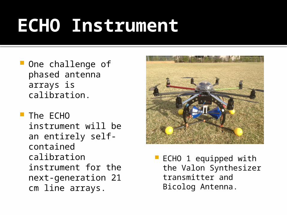
One challenge of phased antenna arrays is calibration.
The ECHO instrument will be an entirely self-contained calibration instrument for the next-generation 21 cm line arrays.
ECHO 1 equipped with the Valon Synthesizer transmitter and Bicolog Antenna.

Goal
The goal of ECHO is to create a known radio signal that our antennas can pick up and calibrate to.
The first step is to create the instrument and then do initial testing on antennas we created before moving onto the hydrogen observatories.
This initial testing has been ongoing since December, 2014.

Challenges
This is a hard thing to do!
Initial hardware was cheap and only a proof of concept. It turned out that it was not capable of the sensitive measurements we needed in the field.
Finding quiet bands to transmit in to remain legal (ISM). Currently we transmit in the middle of the Cell Phone band (915 MHz).
Required, from scratch, building of the drone + transmitter instrument.

Range of the Signal
To be effective, we require at least 1 km of range to fully map the beam pattern of our antennas.
Of April 1st 2015, we can only receive about 121 meters of range before out signal drops to the noise floor.
We recently discovered that the noise in our amplifiers on our receiving antennas gave our less range than if we did not have amplifiers on our antennas. Next, we will move amplification to our transmitter instead.

Beam Pattern Mapping
We want to map the response power of the Antennas. It should have nulls where the signal will all but disappear depending on the angular separation of the antennas.
This sort of test has only yet been done on the FUNcube Dongle (FCD) and not the SignalHound.
The FCD was not sensitive enough to map the nulls of our antennas.
This is a very important step at the heart of this experiment!

Next Steps
Continue to improve hardware to increase range of our signal—place amplifiers onto our transmitters.
Achieve a range of 1 km with our signal.
Redo the beam mapping measurements on the SignalHound setup.
Move the transmitter to the ECHO drone and test the same concept in air, with both range and beam mapping.
We want to test the ECHO instrument on HERA antennas at West Bank on a June 1st deadline.
Publish our calibration results soon after that.

Questions? / Acknowledgements
Thanks to the ASU Space Grant Staff: Dr. Thomas Sharp Candace Jackson Michelle Tanaka
My Mentors: Dr. Judd Bowman Dr. Danny Jacobs Meg Hufford
My Fellow Space Grant Interns The Arizona Space Grant Consortium