Embed Size (px)
Citation preview

APPARECCHIATURA ELETTRONICA pag. 4MANUALE D’INSTALLAZIONE ED USO
ELECTRONIC EQUIPMENT pag. 10INSTALLATION AND OPERATION MANUAL
APPAREILLAGE ELECTRONIQUE pag. 16MANUEL D’ INSTALLATION ET D’ UTILISATION
ELEKTRONIK pag. 22INSTALLATIONS UND BEDIENUNGS
CENTRALITA ELECTRÓNICA pag. 28MANUAL DE INSTALACIÓN Y USO
O&O S.r.l. Via Europa, 2 - 42015 Correggio (R.E.) ItalyPhone 39 0522 740111 - Fax. 39 0522 631290Internet: www.oeo.it - E-mail: [email protected]
ARX.246
EN
FR
DE
ES
IT

DICHIARAZIONE “CE” DI CONFORMITA’(“CE” DECLARATION OF CONFORMITY)
Il costruttore O&O Srl(The manufacturer)Indirizzo Via Europa 2 - 42015 Correggio (RE)(Address)
DICHIARA CHE I SEGUENTI APPARATI(DECLARES THAT THE FOLLOWING EQUIPMENTS)
Descrizione Apparecchiature elettroniche per barriere automatiche(Description) (Control units for automatic barriers)
Modelli ARX.246 ARX.DD3 ARX.DD3 ARX.DD3 ARX.DD3(Models) ARX.246 110V 50Hz 110V 60Hz 220V 50Hz 220V 60Hz
Codici 380750 380782 380783 380780 380781(Codes)
- Risultano conformi con quanto previsto dalle seguenti Direttive Comunitarie, comprese le ultime modifi che e con la legislazione nazionale di recepimento (Are in conformity with the provisions of the following Community Directives, including the latest modifi cations and with the assimilating national legislation) 89/336/CEE 93/68/CEE Compatibilità Elettromagnetica (Electromagnetic Compatibility) 73/23/CEE 93/68/CEE Bassa tensione (Low voltage)
- Rispettano le seguenti (parti/clausole di) norme tecniche armonizzate (Respect the following parts/clauses of harmonized technical standards)
EN 50082-1 EN 50081-1
- Sono conformi alle seguenti (parti/clausole di) norme armonizzate (Are in conformity with the following parts/clauses of harmonized standards)
EN 60335-1
La O&O S.r.l. garantisce detta conformità esclusivamente nel caso in cui le apparecchiature vengano utilizzatate come unità di comando/gestione delle barriere automatiche O&O della serie NIGHT&DAY-3, NIGHT&DAY-5, NIGHT&DAY-DD3, B7000, B8000 nella confi gurazione tipica di installazione e con periferiche conformi alle Direttive Europee.(O&O S.rl. guarantees such a conformity only if the control units are used as a control/management unit for O&O automatic barriers series NIGHT&DAY-3, NIGHT&DAY-5, NIGHT&DAY-DD3, B7000, in typical confi guration of installation and with peri-pherals which conform to the European Directives)
Correggio, 20/05/08
Orlando Mantovani, Presidente e Direttore Tecnico Firma (Signature)
O&O S.r.l.Via Europa, 2 - 42015 Correggio (R.E.) Italy
Tel. +39 0522 740111 - Fax +39 0522 631290Internet: www.oeo.it - E-mail: [email protected]
- AZIENDA CERTIFICATA UNI EN ISO 9001:2000 -
AR
X I
T-G
B
ver.
3

IndiceCapitolo Pagina
1. INTRODUZIONE 5
2. CARATTERISTICHE PRINCIPALI 5
3. NOTA CAVI 5
4. INSIEME DELLE PARTI 5
5. CARATTERISTICHE TECNICHE 5
6. AVVERTENZE 5
7. LEGENDA DEI COMPONENTI 6
8. SETTAGGIO DEI DIP-SWITCH 6
9. SICUREZZA DELL'INSTALLAZIONE 7
10. COLLEGAMENTI E FUNZIONALITA' DI INGRESSI E USCITE 7 10.1 MORSETTIERA DI POTENZA 7 10.2 MORSETTIERA USCITA IN BASSA TENSIONE 7 10.3 MORSETTIERA DI COMANDO INGRESSI 8
11. RICEVENTE RADIO AD INNESTO 8
12. MODALITA' DI LAVORO 9
13. AVARIE SUI COMANDI 9

- 5 -
2. CARATTERISTICHE PRINCIPALI
ARX.246 IT
La centrale di comando ARX.246 è stata sviluppata per gestire barriere monofase serie B e NIGHT&DAY.La notevole disponibilità di logiche selezionabili, consente di soddisfare anche particolari condizioni operative sugli impianti.La rispondenza ai requisiti richiesti dalle Direttive Europee (89/336CEE,73/23CEE e alle loro modifi che successive) dimostra l’elevato standard qualitativo e di sicurezza raggiunto.
1. INTRODUZIONE
CENTRALE DI COMANDO
4. INSIEME DELLE PARTI3. NOTA CAVI
Alimentazione 230Vac ± 10% 50/60Hz (a richiesta 110Vac)Potenza max. assorbita 1.200 WCarico max. accessori 500 mAPotenza max. lamp. barra 20W (24V)Temp. di funzionamento -20° / +70°Grado di protezione IP54Ingombro contenitore L200 x H275 x P130mm
Pos. Descrizione N° cavi Sezione (mm2)
1 Linea di alimentazione 2 + terra 1,5 2 Pulsantiera 4 0,5 3 Selettore a chiave 3 0,5 4 Ricevitore fotocellula 4 0,5 5 Trasmettitore fotocellula 2 0,5 6 Spire magnetiche interrate 7 Segnalatore lampeggiante 2 0,5 8 Radioricevente esterna 4 0,5
5. CARATTERISTICHE TECNICHE
- Uscita per segnalatori luminosi sulla barra.- Uscita per segnalatore lampeggiante.- Predisposta per l’innesto delle riceventi radio a scheda O&O.- Funzione autotest ingressi-uscite del microprocessore.
- Logica a microprocessore.- Led che visualizzano lo stato degli ingressi e delle uscite.- Morsettiere estraibili.- Ingresso per dispositivo di sicurezza "reverser" antischiacciamento
6. AVVERTENZE
Si raccomanda di eseguire un’installazione che preveda tutti gli accessori necessari ad assicurare il funzionamento secondo normativa vigente, impiegando sempre dispositivi originali O&O.L’utilizzo e l’installazione di queste apparecchiature deve rispettare rigorosamente le indicazioni fornite dal costruttore che non può essere considerato responsabile per eventuali danni derivanti da uso improprio o irragionevole.La O&O srl declina ogni responsabilità per le possibili inesattezze contenute nel seguente pieghevole e si riserva il diritto di apportare modifi che in qualsiasi momento senza preavviso alcuno.

- 6 -
Dopo un cambio di posizione dei dip-switch, al fi ne di memorizzare la nuova confi gurazione,
premere il tasto RESET
ATTENZIONEDIP FUNZIONE
1 2 3 LAVORO OFF OFF OFF AUTOTESTOFF ON UOMO PRESENTEON OFF SEMIAUTOMATICOON ON AUTOMATICO
3 CHIUSURA A RILASCIOOFF ESCLUSAON INSERITA
4 5 FOTOCELLULAOFF OFF IN CHIUSURA arresta e attende comandi, a fotocellula liberaOFF ON IN CHIUSURA arresta; richiude, dopo 1", a fotocellula liberaON OFF IN CHIUSURA riapre; richiude, dopo 1", a fotocellula liberaON ON IN CHIUSURA riapre; richiude, dopo 5", a fotocellula libera
6 CONTATTO UTENTE OFF Fotocellula interrotta: contatto cortocircuitato.ON Intervento dispositivo reverser: contatto cortocircuitato per 500 msec.
7 8 REVERSEROFF OFF ESCLUSOOFF ON IN CHIUSURA arresta e attende comandiON OFF IN CHIUSURA riapre e attende comandiON ON IN CHIUSURA riapre; richiude dopo 5"
9 LUCI BARRAOFF Lampeggio in movimentoON Lampeggio in movimento e luci accese a barra chiusa
10 RESET ESTERNOOFF ESCLUSOON INSERITO
DIP-SWITCH DIPROGRAMMA
LGT LUCI BARRAFWR MOTORE - APRELIN MOTORE - LINEAREW MOTORE - CHIUDEUSR CONTATTO UTENTE
LUX FOTOCELLULAAUX INGRESSO AUSILIARIOREV REVERSER FCA FINECORSA APERTURAFCC FINECORSA CHIUSURARUN PULSANTE STARTOPN PULSANTE OPENSTP PULSANTE STOPCLS PULSANTE CLOSERES RESET
LED DI LINEA
LED DI STATO
LED DI CONTROLLO
TRIMMER DI PAUSA ( 0-60'')
COMANDI E CONTROLLI
8. SETTAGGIO DEI DIP-SWITCH
7. LEGENDA DEI COMPONENTI
MORSETTIESTRAIBILI LED DI
CONTROLS
TASTO DI START
TASTO DI RESET
TRIMMER DI PAUSA
MICROPROCESSORE
DIP-SW. DIPROGRAMMAZIONE
TRASFORMATORE
BANCO RELE' STATICI
BANCO FUSIBILI
F1 TRS 250mA - TF2 SLR 250mA - FF3 ENG 6,3A - FF4 LGT 1A - FF5 12V 500mA - FF6 24V 1A - T
CONNETTORERADIO
LED DI STATUS

- 7 -
9. SICUREZZA DELL’INSTALLAZIONE
Affi nché si raggiunga il grado di sicurezza richiesto dalla normativa vigente, leggere attentamente le seguenti prescrizioni.
Realizzare tutti i collegamenti in morsettiera leggendo attentamente le indicazioni riportate in questo manuale ed osservando le norme generali e di buona tecnica che regolano l’esecuzione degli impianti elettrici.Predisporre a monte dell’installazione un interruttore magnetotermico omnipolare con distanza di apertura dei contatti di min. 3 mm.Installare, ove non sia previsto, un interruttore differenziale con soglia 30 mA.Verifi care l’effi cacia dell’impianto di messa a terra e collegare a questa tutte le parti dell’automazione provviste di morsetto o cavo di terra.Prevedere la presenza di almeno un dispositivo di segnalazione esterna, di tipo semaforico o lampeggiante, affi ancato da un cartello segnaletico di pericolo o di avviso.Applicare tutti i dispositivi di sicurezza richiesti dalla tipologia dell’installazione considerando i rischi che essa può causare.Separare nelle canalizzazioni le linee di potenza (sez. min. 1,5 mm2) da quelle di segnale in bassa tensione (sez. min. 0,5 mm2).Ponticellare gli ingressi N.C. non utilizzati.Disporre in serie eventuali contatti da collegare in serie allo stesso ingresso N.C.Disporre in parallelo gli ingressi collegati al medesimo ingresso N.A.
1)
2)3)4)
5)
6)7)8)9)10)
LINEA 230V morsetti 1 - 2 (230V)Alimentazione a 230V 50/60Hz con protezione interna a mov e fusibile (5x20) da 6,3A.Collegare la fase ed il neutro come riportato in serigrafi a mentre la terra va connessa ai morsetti faston EARTH.Utilizzare un cavo tipo H05VV-F 2x1,5+T min.
LAMPEGGIANTE: LUCE GIALLA a 230V 40W max. morsetti 11 - 12 (SLR)Unità per la segnalazione di automatismo in azione; modello SLR.Collegare i morsetti 11 e 12 della centralina rispettivamente ai morsetti N e F del lampeggiatore.L' uscita è protetta con fusibile da 250 mA ( F2 ). N.B.: Adottare solo lampade da 230Vac max 40W.
MOTORE morsetti 4 - 5 - 6 (ENGINE)Uscita motore 230V: MARRONE-4; BLU-5; NERO-6.Il cavo di terra dev'essere collegato ai morsetti EARTH.
10. COLLEGAMENTI E FUNZIONALITA’ DI INGRESSI E USCITE
SLR
11
12
M
AP
C
CH
4
5
6
230 V ~
N
P
1
2
44
USER
45
24 V14
15
24 V17
16
LIGHTS
34
35
USER morsetti 44 - 45Contatto per uso esterno che segnala ogni intervento della fotocellula.Il funzionamento è regolato da programma tramite il Dip 6. Portata del contatto a 230Vac: 4 A.N.B.: Nelle versioni DD3 l'uscita viene utilizzata per comandare l'elettroblocco.
LIGHTS morsetti 34 - 35Si rende disponibile un' uscita 24Vac per l' alimentazione di segnalatori luminosi sulla barra.Collegare i cavi delle lampade (3x24Vac 5W o 6x24Vac 3W), in parallelo ai morsetti 34 - 35.L'uscita è regolabile da programma tramite il Dip 9. Controllo: all'accensione del led LGT si devono accendere tutte le lampade.L'uscita è attiva contestualmente all'acquisto di una barriera con luci o successivamente a seguito dell'acquisto dell'ac-cessorio "maggiorazione per luci".
24 V morsetti 14 - 15Uscita a 24Vac per alimentare accessori di sicurezza e comando come fotocellule o ricevitori radio.
24 V morsetti 17 - 16Uscita a 24Vac per alimentare accessori di sicurezza e comando come fotocellule o ricevitori radio.
10.2 MORSETTIERA USCITA IN BASSA TENSIONE
10.1 MORSETTIERA DI POTENZA

- 8 -
LUX morsetti 18 - 19Ingresso NC di sicurezza (fotocellula). Inserire il programma desiderato mediante i dip 4 e 5. Interviene solo in fase di chiusura; in apertura non interviene mai.
AUX morsetti 24 - 25Ingresso NC di sicurezza (fotocellula).L'ingresso AUX è previsto per una fotocellula supplementare e ne rispecchia le funzioni impostate.
REVERSER morsetti 30 - 31 - 32Viene fornito già cablato e collaudato. Il dispositivo interviene nella sola fase di chiusura quando la barra urta un ostacolo. Inserire il programma desiderato mediante i Dip 7 e 8.Il fi lo marrone va collegato al morsetto 30, il verde al morsetto 31, il bianco al 32.Controllo: ruotando lentamente il dischetto del reverser lampeggia il led REV.
FCA morsetti 20 - 22Ingresso N.C. di fi ne corsa in apertura. Quando viene attivato termina la corsa di apertura.
FCC morsetti 21 - 22Ingresso N.C. di fi ne corsa in chiusura. Quando viene attivato termina la corsa di chiusura.
RUN morsetti 42 - 43Ingresso N.A. che consente di comandare l'automazione secondo la logica programmata tramite i dip 1 e 2.
OPEN morsetti 9 - 8Ingresso N.A. di sola apertura. Collegare qui eventuali orologi o timer giornalieri o settimanali.Mantenendo comandato questo ingresso l’automazione effettuerà la manovra di apertura ed eseguirà l’eventuale richiusura automatica solo quando sarà liberato l’ingresso.
STOP morsetti 7 - 8Ingresso N.C. di sicurezza. Quando viene attivato arresta immediatamente l’automazione e uno start successivo provoca sempre una riapertura. Durante il tempo di pausa (trimmer PAUSE) un comando si stop elimina la richiusura automatica la-sciando la barriera aperta in attesa di comandi. N.B.: A quest'ingresso è già collegato di serie il microinterruttore del portello ed è possibile, come accessorio, collegare anche il kit barra frattura.
CLOSE morsetti 10 - 8Ingresso N.A. di chiusura. Consente di chiudere l’automazione solo se le sicurezze non sono impegnate.
RESET ESTERNO morsetti 40 - 41Per avere la possibilità di bloccare ogni funzione e riportare alle condizioni iniziali la centralina, è previsto un contatto NA sui morsetti 40-41: per inserire la funzione posizionare il dip 10 in ON e collegare ai morsetti un interruttore o un selettore a chiave.
10.3 MORSETTIERA DI COMANDO INGRESSI
42
43RUN
GND
OPEN 9
8GND
REVERSER
GND
+12Vcc
REV
30
31
32
40
RX
41
RESET
18
19
GND
LUX
CLOSE10
8GND
11. RICEVENTE RADIO AD INNESTOSul connettore J2 è possibile inserire i ricevitori radio modello O&O.Scheda per il comando della barriera mediante trasmettitori radio.Inserire la scheda radioricevente (RX1) nel connettore J2 e leggere le istruzioni allegate.Il segnale radio agisce come comando di Start. E' possibile anche l'utilizzo della scheda radio RX2; in tal caso ponticellare PT1.Collegare l’eventuale antenna accordata sul morsetto antenna della ricevente radio.
24
25
AUX
GND
20
22
FCA
GND
21
22
FCC
GND
GND8
7STOP

AUTOTEST
Settando questa modalità la centralina opera un controllo funzionale dei programmi interni al microprocessore e delle periferiche ad esso connesse.
In particolare: - i leds di controllo servono per una verifi ca delle connessioni esterne alla centralina; - i leds di status verifi cano lo stato interno della centralina. Procedura: Posizionare i dip 1, 2 e 3 in OFF e premere il pulsante reset.
# Controllo: Dovranno lampeggiare contemporaneamente tutti i Leds di controllo, eccetto quelli relativi ai contatti NC (che resteranno accesi) e i leds REV e RES che rimarranno spenti.
I Leds di status dovranno invece accendersi in sequenza. Verifi ca: Agendo sul trimmer di regolazione TM1 (PAUSE), dovrà variare la frequenza di lampeggio dei Leds di controllo e la
velocità sequenziale di accensione dei Leds di status: tale comportamento segnala che il microprocessore opera cor-rettamente. La mancata accensione di uno o piu' Leds di status indica un guasto della centralina.
Il mancato lampeggio di uno dei Leds di controllo segnala un problema sul collegamento dell'unità esterna corrispon-dente.
UOMO PRESENTE
Il funzionamento della barra avviene per pressione continua sui pulsanti di Apre o di Chiude.Tenendo premuto Apre la barra si alza e a fi necorsa il motore si arresta.Tenendo premuto Chiude la barra si abbassa e a fi necorsa il motore si arresta.La Fotocellula interviene sia in fase di apertura che in chiusura: per riprendere il normale funzionamento occorre rilasciare il comando interrotto e impatirne uno nuovo. Sono esclusi i dip 3, 4, e 5, il Timer di Lavoro, RX1 e RUN.Il reverser segue il programma selezionato tramite i dip 7 e 8 tranne nella confi gurazione ON/ON in cui arresta e riapre sino a FCA. Per riattivare i comandi è necessario dare un comando Stop.
SEMIAUTOMATICO
Il funzionamento della barra avviene per impulsi (la cui durata non deve superare il tempo di lavoro) sui pulsanti di Start, Apre o Chiude e il comando opera una sola fase del ciclo di funzionamento (apertura o chiusura).Il dip 3 inserisce o meno la chiusura a rilascio.
AUTOMATICO
Il funzionamento della barra avviene per impulsi (di durata inferiore al tempo di lavoro) sui pulsanti di Start, Apre o Chiude.Se l’operazione è di apertura, una volta arrivata a fi necorsa (FCA), la barra attende un certo tempo, impostato tramite il trimmer TM1, quindi procede automaticamente a richiudersi. Il dip 3 inserisce o meno la chiusura a rilascio. I dip 4 e 5 propongono le sequenze di Fotocellula.
CHIUSURA A RILASCIO Modalità di funzionamento studiata per ottenere la chiusura automatica della barra solo quando la vettura ha abbandonato la fotocellula o il rilevatore magnetico (accessori piu' idonei per questo utilizzo). Collegare il contatto NA del rilevatore o della fotocellula ai morsetti 8-10 (contatto Chiude) e posizionare il dip 3 in ON.La presenza della vettura sul rilevatore o davanti alla fotocellula non provoca l'immediata chiusura bensì occorre attendere il rilascio del relativo segnale.
12. MODALITA' DI LAVORO
Avaria del comando STOP (NC) Il led STP risulta, in condizioni normali, sempre acceso.Il suo spegnimento, non provocato da alcun comando, indica che il contatto Chiude è erroneamente aperto.Nessun comando risulta operativo fi nchè il contatto non è riportato nella confi gurazione NC.
Avaria dei comandi Apre (NA), Chiude (NA), Start (NA)I rispettivi leds OPN, CLS, RUN sono spenti in condizioni normali. Se uno dei contatti risulta erroneamente cortocircuitato, il rispettivo led rimane acceso e gli altri comandi non sono operativi.Ripristinare la confi gurazione NA per riprendere il normale funzionamento.
13. AVARIE SUI COMANDI

- 10 -
IndexChapter Page
1. INTRODUCTION 11
2. MAIN CHARACTERISTICS 11
3. CABLES NOTE 11
4. SET OF PARTS 11
5. TECHNICAL SPECIFICATIONS 11
6. IMPORTANT NOTICES 11
7. ELECTRONIC EQUIPMENT 12
8. DIP-SWITCH SETTING 12
9. INSTALLATION SAFETY 13
10. INPUT AND OUTPUT FUNCTIONALITY AND CONNECTIONS 13 10.1 POWER TERMINAL BLOCKS 13 10.2 LOW VOLTAGE OUTPUT TERMINAL BLOCKS 13 10.3 INPUTS CONTROL TERMINAL BLOCKS 14
11. PLUG-IN RADIO RECEIVER 14
12. WAYS OF WORKS 15
13. CONTROL FAULTS 15

- 11 -
2. MAIN CHARACTERISTICS
ARX.246 EN
The control unit ARX.246 is designed to govern NIGHT&DAY and B series single-phase barriers.The considerable number of logic units available permits satisfying even special operating conditions on systems.Compliance with the requirements of European Directives (89/336/EEC, 73/23/EEC and subsequent amendments) demonstrates the high standards of quality and safety reached.
1. INTRODUCTION
ELECTRONIC CONTROL UNIT
4. SET OF PARTS3. CABLES NOTE
Power supply 230Vac ± 10% 50/60Hz (110Vac on request)Max. power absorbed 1,200 WMax accessory load 500 mAMax. bar lamp power 20W (24V)Operating temp. -20° / +70°Protection level IP54Housing dimensions: W200 x H275 x D130mm
Pos. Description N° cables Min. Cross (mm2)
1 Power cable 2+Earth 1.5 2 Push-button control panel 4 0.5 3 Keyed switch unit 3 0.5 4 Photocell receiver 4 0.5 5 Photocell transmitter 2 0.5 6 Buried magnetic coils 7 Flashing indicator 2 0.5 8 External radio receiver 4 0.5
5. TECHNICAL SPECIFICATIONS
- Output for luminous indicators on the bar.- Output for a fl ashing indicator.- Fitted for plugging in radio receivers on an O&O card- Microprocessor I/O self-test function.
- Microprocessor logic - LEDs displaying input status- Removable terminal blocks- Input for the “reverser” anticrushing safety device
6. IMPORTANT NOTICES
It is recommended to make an installation which has all the accessories necessary to ensure operation according to current provisions, always using genuine O&O devices.This equipment must be installed and used in strict compliance with the manufacturer’s instructions.The manufacturer cannot be held responsible for any damage deriving from improper or unreasonable use.O&O srl disclaims all liability for any inaccuracies contained in this booklet and reserves the right to make changes at any time without any prior notice whatsoever.

- 12 -
After changing dip-switch settings, press the RESET button to enter and store the new
confi guration.
IMPORTANT
DIP FUNCTION
1 2 3 OPERATION OFF OFF OFF AUTOTESTOFF ON MANUALON OFF SEMI-AUTOMATICON ON AUTOMATIC
3 PRESS AND RELEASE CLOSUREOFF DEACTIVATEDON ACTIVATED
4 5 PHOTOCELLOFF OFF IF ENGAGED DURING CLOSURE, stops movement and waits for commands when disengaged againOFF ON IF ENGAGED DURING CLOSURE, stops then re-closes after 1.0 sec. once disengagedON OFF IF ENGAGED DURING CLOSURE, re-opens then re-closes after 1.0 sec. once disengagedON ON IF ENGAGED DURING CLOSURE, re-opens then re-closes aftrer 5.0 sec. once disengaged
6 AUXILIARY CIRCUIT BREAKER OFF Interrupted photocell: contact has short circuitedON Reverser intervention:contact short-circuited for 500 msec.
7 8 REVERSEROFF OFF DEACTIVATEDOFF ON DURING CLOSURE, stops then waits for commandsON OFF DURING CLOSURE, stops, re-opens, then waits forcommandsON ON DURING CLOSURE, stops then re-closes gate after 5.0 sec.
9 BARRIER LIGHTSOFF Flashing during movementON Flashing during movement, lit with barrier closed
10 EXTERNAL RESETOFF DeactivatedON Activated
PROGRAMMINGDIP-SWITCH
LGT BARRIERS LIGTHSFWR MOTOR OPENINGLIN MOTOR ON LINEREW MOTOR CLOSINGUSR AUXILIARY CIRCUIT BREAKER
LUX PHOTOCELLAUX AUXILIARY IMPUTREV REVERSER FCA OPENING TRAVEL STOP FCC CLOSING TRAVEL STOPRUN START BUTTONOPN OPEN BUTTONSTP STOP BUTTONCLS CLOSE BUTTONRES RESET
PAUSE TIMER
( 0-60'')
PROGRAMS AND FUNCTIONS
8. DIP-SWITCH SETTINGS
LINE LED
STATUS LEDS
CONTROL LEDS
7. ELECTRONIC EQUIPMENT
REMOVABLE TERMINALS CONTROL
LEDS
START BUTTON
RESET BUTTON
PAUSE TIMER
MICROPROCESSOR
PROGRAMMINGDIP- SWITCH
TRANSFORMER
STATIC RELAY BANK
FUSE GROUP
F1 TRS 250mA - TF2 SLR 250mA - FF3 ENG 6,3A - FF4 LGT 1A - FF5 12V 500mA - FF6 24V 1A - T
RADIOCONNECTOR
STATUS LED

- 13 -
9. INSTALLATION SAFETY
In order to achieve the degree of safety required by existing laws and standards please read the following instructions carefully.
Make all the connections in the terminal block after carefully reading the instructions given in this manual and observing the general rules and technical standards governing electrical systems.Upstream from the installation, fi t an omnipole miniature circuit breaker with a contact gap of at least 3 mm.If there isn’t one already, install a residual current device with a threshold of 30 mA.Check the effectiveness of the grounding system and connect to it all the parts of the automation fi tted with a terminal or grounding cable.Fit at least one external warning device, such as a traffi c light or fl ashing light, along with a warning or danger sign.Fit all the safety devices required by the type of installation, taking into consideration the risks it can cause.Separate the power lines (min. sect. 1.5 mm2) from the low-voltage signal lines (min. sect. 0,5 mm2) in the ducts.Fit jumpers in the N.C. inputs not used.Set in series any contacts to be connected in series with the same N.C. input.Set in parallel the inputs connected to the same N.O. input.
1)
2)3)4)
5)6)7)8)9)10)
LINE 230V terminals 1 - 2 (230V)230V 50/60Hz power supply with mov internal protection and 6,3A fuse (5x20).Connect the phase and neutral as shown on the screen printing while ground should be connected to the EARTH Faston terminals. Use a cable type H05VV-F 2x1.5+E min.
FLASHING LIGHT: YELLOW at 230V 100W max terminals 11 - 12 (SLR)Unit to signal the automatism is operating; model SLR.Connect terminals 11 and 12 of the unit to terminals N and F respectively of the fl ashing lamp.The output is protected by a 250 mA fuse (F2). Note: Only use 230Vac max 40W lamps.
MOTOR terminals 4 - 5 - 6 (ENGINE)Motor output 230V: BROWN-4; BLUE-5; BLACK-6.The earth cable must be connected to the EARTH terminals.
10. INPUT AND OUTPUT FUNCTIONALITY AND CONNECTIONS
SLR
11
12
M
AP
C
CH
4
5
6
230 V ~
N
P
1
2
44
USER
45
24 V14
15
24 V17
16
LIGHTS
34
35
USER terminals 44 - 45Contact for external use, designed to signal any operation of the photocell.The contact breaker is programmed by dip-switch 6. Circuit breaker rating: 230 Vac, 4 A.NOTE: The output in the DD3 versions is used to control the electric lock.
LIGHTS terminals 34 - 35A 24 Vac output is made available to power the function indicators of the barrier.Connect the indicator cables in parallel to terminals 34-35. Output is programmed by dip-switch 9 .Check: all the indicators should ligth when status led LGT lights. The output is active immediately after the purchase of a barrier with lights or subsequently after the purchase of the “light arrangement” accessory.
24 V terminals 14 - 1524Vac output to power the safety and control accessories like photocells or radio receivers.
24 V terminals 17 - 1624Vac output to power the safety and control accessories like photocells or radio receivers.
10.2 LOW VOLTAGE OUTPUT TERMINAL BLOCK
10.1 POWER TERMINAL BLOCK

- 14 -
LUX terminals 18 - 19NC safety input (photocell). Enter the programme wanted with dip switches 4 and 5. It triggers only in the closing phase; it never triggers in opening.
AUX terminals 24 - 25NC safety input (photocell).The AUX input is for an additional photocell and it refl ects the functions set.
REVERSER terminals 30 - 31 - 32It is supplied already wired and tested. It triggers only in the closing phase when the bar knocks against an obstacle. Enter the programme wanted with dip switches 7 and 8.Connect the brown wire to terminal 30, the green to terminal 31 and the white to terminal 32.Check: that when the reverser disc is turned slowly the REV LED fl ashes.
FCA terminals 20 - 22Limit switch N.C. input in opening. When activated the opening travel fi nishes.
FCC terminals 21 - 22Limit switch N.C. input in closing. When activated the closing travel fi nishes.
RUN terminals 42 - 43N.O. input that allows the automation to be controlled according to a logic programmed with dip switches 1 and 2.
OPEN terminals 9 - 8N.O. input - opening only Connect clocks, daily timers or weekly timers here if wanted.By keeping this input controlled, the automation performs the opening manoeuvre and will close automatically only when the input is freed.
STOP terminals 7 - 8N.C. safety input. When activated it stops the automation instantly and a subsequent start always cause reopening. During pause time (PAUSE trimmer) a stop command disables automatic reclosing, leaving the bar open waiting for commands. NOTE: The hatch microswitch is already connected to this input and it is possible to connect the pushed bar kit as well as an accessory.
CLOSE terminals 10 - 8N.O. input for closing. It allows the automation to be closed only if the safety devices have not triggered.
EXTERNAL RESET terminals 40 - 41To be able to block all functions and reset the control unit at its initial conditions there is a NO contact on terminals 40-41: to add the function, position dipswitch 10 ON and connect either a switch or key selector to the terminals.
10.3 INPUTS CONTROL TERMINAL BLOCKS
42
43RUN
GND
GND8
7STOP
OPEN 9
8GND
REVERSER
GND
+12Vcc
REV
30
31
32
40
RX
41
RESET
18
19
GND
LUX
CLOSE10
8GND
11. PLUG-IN RADIO RECEIVERThe O&O model radio receivers can be plugged into connector J2.Board for controlling the bar by means of radio transmitters.Plug the radio receiver board (RX1) into connector J2 and read the enclosed instructions.The radio signal acts as a Start command. It is also possible to use the radio board RX2; in this case jumper PT1.Connect the wired antenna, if any, to the radio receiver’s antenna terminal.
24
25
AUX
GND
20
22
FCA
GND
21
22
FCC
GND

- 15 -
TEST MODE
In test mode, a functional test is performed on the controller. This test examines the internal programs of the microprocessor and any peripherals connected to it. In particular: - the control leds confi rm external connection to the controller - the status leds confi rm the internal conditions of the controller
Procedure: Set DIP switches 1, 2 , 3 OFF and press reset.
# Check: All control leds should fl ash simultaneously, except for those for NC contacts (that remain lit), and the REV and RES leds, that remain switched off. The status LEDs should light in sequence. Test: Check that as you trimmer TM1 (PAUSE) the fl ashing frequency of the control LEDS varies and the status LED sequence changes speed. This shows that the microprocessor is functioning correctly. If Status relay fails to operate, the controller is probably faulty. Failure of one or more status leds to illuminate indicates a controller fault. Failure of one of the control leds to illuminate indicates a fault in the connection to the corresponding external unit.
MANUAL MODE
In manual mode, hold down the Opening and Closing button to operate the barrier. When you hold the Open button down, the barrier lifts, and the motor stops when the barrier reaches the end of its travel.When you hold the Close button down, the barrier lowers, and the motor stops when the barrier reaches the end of its travel.The photocell is engaged in both opening and closing phases; to resume normal operation, release the interrupted command and repeat. Dip switches 3, 4 , and 5, Operation Timer, RX1 and Serial are inhibited. The reverser operates as programmed, unless DIP switches 7 and 8 are ON, in this case it stops the barrier and re-opens as far as FCA, and commands are re-enabled only after the Stop button is pressed.
SEMIAUTOMATIC MODE
The barrier is operated by pressing without holding the Start, Open, and Close buttons.The duration of pressing won' t be longes than operating time.Commands generate complete opening or closing cycles. DIP switch 3 controls press and release closure.
AUTOMATIC MODE
The barrier is operated by pressing without holding the Start, Open, and Close buttons.The duration of pressing won' t be longes than operating time.In the opening phase, once the barrier reaches travel stop (FCA), it waits for an interval, set by means of trimmer TM1, and then proceeds automatically with closure.
PRESS AND RELEASE CLOSURE
This mode is designed for automatic closure of the barrier only when the vehicle has crossed the photocell or magnetic detector (acces-sories most suitable for this system).Connect the NO contact of the detector or photocell to terminals 8-10 (Close contact) and set dip switch 3 to ON.The presence of a vehicle over the detector or in front of the photocell does not cause immediate closure; this only occurs following the relative signal.
12. WAYS OF WORK
Stop command fault (NC)The STP led under normal conditions remains permanently lit. If it switches off, this indicates that the Close contact has opened due to an error in operation. No command is operative until this contact is reset to NC.
Open (NO), Close (NO), Start (NO) command faults The OPN, CLS, and RUN leds remain off under normal conditions. If one of these should short circuit, the respective led illuminates and the other commands are no longer operative. Reset to NO to resume normal operation.
13. CONTROL FAULTS

- 16 -
SommaireChapitre Page
1. AVANT-PROPOS 17
2. CARACTERISTIQUES PRINCIPALES 17
3. SCHEMA DES CABLES 17
4. COMPOSITION 17
5. CARACTERISTIQUES TECHNIQUES 17
6. MISE EN GARDE 17
7. APPAREILLAGE ELECTRONIQUE 18
8. RÉGLAGE DES COMMUTATEURS 18
9. SECURITE DE L’INSTALLATION 19
10. CONNEXIONS ET DESCRIPTION DES ENTRÉES ET DES SORTIES 19 10.1 BORNIER D’ALIMENTATION 19 10.2 BORNIER SORTIE EN BASSE TENSION 19 10.3 BORNIER DE COMMANDE ENTREES 20
11. RECEPTEUR RADIO ENFICHABLE 20
12. INSTRUCTIONS DE SERVICE 21
13. PANNES DE COMMANDE 21

- 17 -
2. CARACTERISTIQUES PRINCIPALES
ARX.246 FR
La centrale de commande ARX.246 à été étudiée et développée barrières monophasées séries B et NIGHT&DAY.La grande disponibilité de logiques sélectionnables permet de satisfaire les conditions particulières d’exercice des installations.La conformité aux prescriptions des directives européennes (89/336CEE,73/23CEE et à leurs amendements successifs) prouve le grand standard de qualité et de sécurité.
1. AVANT-PROPOS
CENTRALE ELECTRONIQUE
4. COMPOSITION3. SCHEMA DES CABLES
Alimentation 230Vca ± 10% 50/60Hz (sur demande 110Vca)Puissance absorbée max. 1.200 WCharge max. accessoires 500 mAPuissance max. clign. lisse 20W (24V)Temp. de fonctionnement -20° / +70°Degré de protection IP54Dim. hors tout boîtier L200 x H275 x P130mm
Pos. Description Nb câbles Section (mm2)
1 Ligne monophasée 2 + terre 1,5 2 Boitier boutos poussoirs 4 0,5 3 Sélecteur à clé 3 0,5 4 Cell. pho. récept. 4 0,5 5 Cell. pho. transm. 2 0,5 6 Spires magnétiques enfouies 7 Indicateur clignotant 2 0,5 8 Récepteur radio externe 4 0,5
5. CARACTERISTIQUES TECHNIQUES
- Sortie pour indicateurs lumineux sur la lisse.- Sortie pour indicateur clignotant.- Prédisposition pour accueillir les récepteurs radio à carte O&O- Fonction autotest entrées - sorties du microprocesseur.
- Logique à microprocesseur - Diodes qui affi chent l’état des entrées- Borniers extractibles- Entrées pour dispositif de sécurité "inverseur" anti-écrasement
6. MISE EN GARDE
Il est conseillé de réaliser une installation prévoyant tous les accessoires nécessaires à assurer un fonctionnement conforme à la légi-slation en vigueur en utilisant toujours des dispositifs d’origine O&O.L’utilisation et l’installation de ces appareils doit rigoureusement respecter les indications fournies par le fabricant O&O.Ce dernier est exonéré de toute responsabilité en cas de dégâts provoqués par un usage impropre ou déraisonnable.O&O srl décline toute responsabilité en cas d’erreurs ou d’inexactitudes contenues dans ce mode d’emploi.Elle se réserve aussi le droit d’apporter toutes les modifi cations qu’elle jugera utiles, à tout moment et sans aucun préavis.

- 18 -
Après une modifi cation de confi guration des dip-switches, sauvegarder la modifi cation
par RESET
ATTENTION
DIP FUNCTION
1 2 3 SERVICE OFF OFF OFF AUTOTESTOFF ON PERSONNE PRESENTEON OFF SEMI-AUTOMATIQUEON ON AUTOMATIQUE
3 FERMETURE EN RELACHANTOFF EXCLUEON ENCLENCHEE
4 5 CELLULE PHOTOELECTRIQUEOFF OFF EN FERMETURE, arrète et attend commandes cellule libre.OFF ON EN FERMETURE, arrète; referme après 1.0 sec., cellule libre.ON OFF EN FERMETURE, rouvre; referme après 1.0 sec., cellule libre. ON ON EN FERMETURE, rouvre; referme après 5.0 sec., cellule libre.
6 CONTACT AUXILIAIRE OFF Cellule photoélectrique interrompue: contact en cort-circuitON Intervention du reverser: contact en court-circuit pendant 500 msec.
7 8 REVERSEROFF OFF EXCLUOFF ON EN FERMETURE, arrète et attend les commandesON OFF EN FERMETURE, rouvre; attend les commandes ON ON EN FERMETURE, rouvre; referme après 5.0 sec.
9 ECLAIRAGE BARRIEREOFF CLIGNOTANT EN MOUVEMENT ON CLIGNOTANT EN MOUVEMENT ET ECLAIRAGE D'ACCES AVEC BARRIERE FERMEE
10 RETABLISSEMENT (RESET EXTERIEUR)OFF EXCLUON INCLU
DIP-SWITCH DEPROGRAMME
LGT ECLAIRAGE BARRIEREFWR MOTEUR EN OUVERTURELIN MOTEUR EN LIGNEREW MOTEUR EN FERMETUREUSR CONTACT AUXILIAIRE
LUX CELLULE PHOTOELECTRIQUEAUX ENTREE AUXILIAIREREV REVERSER FCA FIN DE COURSE OUVERTUREFCC FIN DE COURSE FERMETURERUN POUSSOIR STARTOPN POUSSOIR OUVRESTP POUSSOIR STOPCLS POUSSOIR FERMERES RESET
TRIMMER DE PAUSE
( 0-60'')
COMMANDES ET CONTROLES
8. RÉGLAGE DES COMMUTATEURS
LED DE TENSION
LED D'ETATS
LED DE CONTROLE
7. APPAREILLAGE ELECTRONIQUE
BORNES DEBLO-CHABLES LEDS DE
CONTROLE
TOUCHE START
TOUCHE RESET
REGLAGE DU TEMPS DE PAUSE
MICROPROCESSEUR
MICRO INTERR.DE PROGRAMME
TRANSFORMATEUR
GROUPE RELAISSTATIQUES
GROUPE FUSIBLES
F1 TRS 250mA - TF2 SLR 250mA - FF3 ENG 6,3A - FF4 LGT 1A - FF5 12V 500mA - FF6 24V 1A - T CONNECTEUR
RADIO
LEDS D’ETATS

- 19 -
9. SECURITE DE L’INSTALLATION
Pour atteindre le degré de sécurité requis par la législation en vigueur, lisez attentivement et suivez les prescriptions suivantes
Tous les branchements dans le bornier doivent être effectués après avoir lu attentivement les indications reportées dans ce mode d’emploi et en suivant les règles générales et de bonne technique qui règlent la réalisation des installations électriques. Prévoyez en amont de l’installation un disjoncteur omnipolaire avec une distance d’ouverture des contacts de 3 mm min.Installez, où il n’est pas prévu, un interrupteur différentiel avec un seuil de 30 mA.Vérifi ez l’effi cacité de la mise à la terre et reliez-y tous les composants de l’automation dotés d’une borne ou d’un fi l de terre. Prévoyez la présence d’au moins un signal externe de type “feux rouges” ou clignotant ainsi qu’un panneau signalant le danger ou d’avertissement. Appliquez tous les dispositifs de sécurité requis par le type d’installation en prenant en compte les risques qu’elle peut provoquer. Dans les goulottes, séparez les lignes d’alimentation (sec. min. 1,5 mm2) de celles de signal en basse tension (sec. min. 0,5 mm2).Court-circuitez les entrées N.F. inutilisées.Disposez en série les contacts éventuels à brancher en série à la même entrée N.F.Disposez en parallèle les entrées reliées à la même entrée N.O.
1)
2)3)4)5)
6)7)8)9)10)
LIGNE 230V bornes 1 - 2 (230V)Alimentation à 230V 50/60Hz avec protection interne à mov et fusible (5x20) de 6,3A.Branchez la phase et le neutre comme reporté sur la plaquette, tandis que le fi l de terre doit être branché aux bornes faston EARTH. Utilisez un câble type H05VV-F 2x1,5+T min.
CLIGNOTANT: FEU JAUNE à 230V 40W max. bornes 11 - 12 (SLR)Unité de signal automatisme en marche; modèle SLR.Brancher respectivement les bornes 11 et 12 de la centrale aux bornes N et F du clignotant.La sortie est protégée par un fusible de 250 mA (F2). N.B.: utiliser uniquement des ampoules de 230Vca max. 40W.
MOTEUR bornes 4 - 5 - 6 (ENGINE)Sortie moteur 230V: MARRON-4; BLEU-5; NOIR-6.Le câble de terre doit être branché aux bornes EARTH.
10. CONNEXIONS ET DESCRIPTION DES ENTRÉES ET DES SORTIES
SLR
11
12
M
AP
C
CH
4
5
6
230 V ~
N
P
1
2
44
USER
45
24 V
14
15
24 V
17
16
LIGHTS
34
35
USER bornes 44 - 45Contact prévu pour utilisation externe pour signaler chaque intervention de la cellule photoélectrique.Le fonctionnement est régulé par le programme par l'intermédiaire du Commutateur 6. Portée du contact à 230Vca: 4 A.N.B.: sur les versions DD3, la sortie est utilisée pour commander le verrouillage électrique.
LIGHTS bornes 34 - 35Est également disponible une sortie 24Vca pour l'alimentation d'indicateurs lumineux sur la lisse.Brancher les câbles des ampoules (3x24Vca 5W ou 6x24Vca 3W) en parallèle aux bornes 34 - 35.La sortie est réglable par le programme par l'intermédiaire du Commutateur 9. Contrôle: à l'allumage du voyant LGT, toutes les ampoules doivent s'allumer.La sortie est active à l'achat d'une lisse avec lumières ou par la suite après achat de l'accessoire "majoration pour lumières".
24 V bornes 14 - 15Sortie à 24Vca pour alimenter accessoires de sécurité et commande tels que cellules photoélectriques ou récepteurs radio.
24 V bornes 17 - 16Sortie à 24Vca pour alimenter accessoires de sécurité et commande tels que cellules photoélectriques ou récepteurs radio.
10.2 BORNIER SORTIE EN BASSE TENSION
10.1 BORNIER D’ALIMENTATION

- 20 -
LUX bornes 18 - 19Entrée NF de sécurité (cellule photoélectrique). Sélectionner le programme voulu à l'aide des commutateurs 4 et 5.Intervient uniquement en phase de fermeture; n'intervient jamais en ouverture.
AUX bornes 24 - 25Entrée NF de sécurité (cellule photoélectrique).L'entrée AUX est prévue pour une cellule photoélectrique supplémentaire et en refl ète les fonctions programmées.
INVERSEUR bornes 30 - 31 - 32L'inverseur est fourni câblé et contrôlé. Le dispositif intervient uniquement en phase de fermeture quand la lisse rencontre un obstacle. Sélectionner le programme voulu à l'aide des commutateurs 7 et 8.Le fi l marron doit être branché à la borne 30, le fi l vert à la borne 31 et le blanc à la borne 32.Contrôle: en faisant pivoter lentement le disque de l'inverseur, le voyant REV clignote.
FCA bornes 20 - 22Entrée N.F. de fi n de course en ouverture. Quand elle est activée, la course d'ouverture est arrêtée.
FCC bornes 21 - 22Entrée N.F. de fi n de course en fermeture. Quand elle est activée, la course de fermeture est arrêtée.
START bornes 42 - 43Entrée N.O. qui permet de commande l'automation selon la logique programmée par l'intermédiaire des commutateurs 1 et 2.
OUVERTURE bornes 9 - 8Entrée N.O. d’ouverture seulement. On y connecte les horloges ou les temporisateurs journaliers ou hebdomadaires.En maintenant l’actionnement de cette entrée, l’automation effectuera la manœuvre d’ouverture et effectuera la refermeture automatique éventuelle, seulement lorsque l’entrée sera désactivée.
STOP bornes 7 - 8Entrée N.F. de sécurité. Son activation arrête immédiatement l’automation et un start successif provoque toujours une rou-verture. Pendant le temps de pause (potentiomètre PAUSE) une commande de stop élimine la refermeture automatique en laissant le portail ouvert dans l’attente de commandes. N.B.: à cette entrée, est déjà branché en série le micro-interrupteur du volet et il est possible, comme accessoire, de brancher également le kit lisse brisée.
FERMETEUR bornes 10 - 8Entrée N.O. de fermeture. Elle ferme l’automation, mais seulement si les dispositifs de sécurité n’ont pas été activés.
RÉINITIALISATION EXTERNE bornes 40 - 41Pour disposer de la possibilité de bloquer toute fonction et de replacer la centrale dans les conditions initiales, un contact NO est prévu sur les bornes 40-41: pour activer la fonction, placer le commutateur 10 sur la position ON et brancher un interrup-teur ou un sélecteur à clé aux bornes.
10.3 BORNIER DE COMMANDE ENTREES
42
43RUN
GND
GND8
7STOP
OPEN 9
8GND
REVERSER
GND
+12Vcc
REV
30
31
32
40R
X
41
RESET
18
19
GND
LUX
CLOSE10
8GND
11. RECEPTEUR RADIO ENFICHABLESur le connecteur J2, il est possible de brancher les récepteurs radio modèle O&O.Carte de commande de la barrière par l'intermédiaire d'émetteurs radio.Placer la carte de réception radio (RX1) sur le connecteur J2 et lire les instructions jointes en annexe.Le signal radio agit comme commande de Start. Il est également possible d'utiliser la carte radio RX2; dans ce cas, placer un cavalier sur PT1.Brancher l'éventuelle antenne accordée à la borne antenne du récepteur radio.
24
25
AUX
GND
20
22
FCA
GND
21
22
FCC
GND

- 21 -
AUTOTEST
En sélectionnant cette procédure, on effectue un essai de fonctionnement sur la centrale qui contrôlera les programmes intérieurs et extérieurs au microprocesseur et connectés à ce dernier. En particulier: - Les leds de contrôle servent à une vérifi cation des raccordements externes de la centrale. - Les leds d’état vérifi ent l’état interne de la centrale.
Procédure : Placer les dip 1, 2 et 3 sur OFF. Envoyer la commande de reset.
# Contrôle: Toutes les leds de contrôle devront clignoter simultanément à l’exception des leds relatives aux contacts NF (qui restent allumées) et les leds REV et RES qui resteront éteintes. Les leds d’états devront s’allumer par contre en séquence. § Vérifi cation: En agissant sur le temporisateur de réglage TM1 (PAUSE) la fréquence de clignotement des led de contrôle devra varier, ainsi que la vitesse séquentielle des leds d'état. Cette variation indique que le processeur agit correctement. Si une des led d'état ne s'allume pas cela signifi que que la centrale à une panne. Si une des led de contrôle ne s’allume pas, cela indique une panne sur le raccordement externe correspondant.
PERSONNE PRESENTE
On actionne la barrière en appuyant continuellement sur les poussoirs Ouvre ou Ferme. En maintenant enfoncé Ouvre la barrière se lève. Arrivé en fi n de course le moteur s'arrête.En maintenant enfoncé Ferme la barrière se baisse. Arrivé en fi n de course le moteur s'arrête.La photocellule intervient en phase d'ouverture et de fermeture:pour rètablir le fonctionnement normal, relâcher la commande interrompue et donner une autre commande.Les Dip 3, 4 et 5, Timer, RX1 et Serial sont exclus.Le Reverser exécute le programme par les dip 7 et 8 excepté les confi gurations ON/ON pour lesquelles le Reverser ouvre et ferme jusqu’au fi n de course ouvert. Pour R.A.Z les commandes, un Stop est indispensable.
SEMI-AUTOMATIQUE
Le fonctionnement de la barrière s'effectue grâce aux impulsions sur Start, Ouvre ou Ferme (qui doivent terminer avant la fi n du temps de travail) et la commande effectuera seulement une phase du cycle de fonctionnement (fermeture ou ouverture).Le dip 3 enclenché ou non valide la fermeture conditionnée.
AUTOMATIQUE
Le fonctionnement de la barrière s'effectue grâce aux impulsions sur Start, Ouvre ou Ferme ( qui doivent terminer avant la fi n du temps de travail). En cours d’ouverture, une fois le fi n de course ouverture atteint, la barrière connaît un temps d’arrêt (réglé par le trimmer TM1), et se referme automatiquement. Le dip 3 enclencle ou non la fermeture conditionnée.Les dip 4 et 5 proposent les séquences de la cellule photoélectrique.
FERMETURE CONDITIONNEE
Mode de fonctionnement prévu pour que la barrière ne se ferme qu’après départ du véhicule (désexcitation de la photocellule ou du capteur magnétique (accessoires le plus idoines à cette utilisation). Relier le contact NO du capteur ou de la photocellule aux bornes 8-10 (contact Ferme) et positionner le dip 3 sur ON. La présence du véhicule sur le capteur ou devant la cellule ne provoque pas la fermeture immédiate. Cette fermeture ne se fera qu’à la fi n du signal.
12. INSTRUCTIONS DE SERVICE
Panne de la commande de Stop (NF). La led STP est, en conditions normales, toujours allumée. Son extinction non provoquée par une commande indique que le contact ferme est ouvert par erreur. Aucune commande ne sera validée tant que le contact ne retrouve pas sa condition de NF.
Panne des commandes de ouvre (NO), ferme (NF) et Start (NO).Les led correspondantes OPN, CLS, RUN sont éteintes en conditions normales.Si l’un de contacts est court-circuité par erreur, la led correspondante reste allumée et les autres commandes ne seront pas activées.Il faut rétablir la confi guration NO pour rentrer dans le fonctionnement normal.
13. PANNES DE COMMANDE

- 22 -
InhaltKapitel Seite
1. EINLEITUNG 23
2. HAUPTEIGENSCHAFTEN 23
3. HINWEISE ZU DEN KABELN 23
4. GESAMTHEIT DER TEILE 23
5. TECHNISCHE EIGENSCHAFTEN 23
6. WICHTIGE HINWEISE 23
7. ELEKTRONIK 24
8. EINSTELLEN DER DIP SWITCHES 24
9.SICHERHEIT DER INSTALLATION 25
10. ANSCHLÜSSE UND FUNKTION DER EIN- UND AUSGÄNGE 25 10.1 LEISTUNGSKLEMMENBRETT 25 10.2 KLEMMENBRETT FÜR NIEDERSPANNUNGSAUSGÄNGE 25 10.3 KLEMMENBRETT ZUR STEUERUNG DER EINGÄNGE 26
11. STECK-FUNKEMPFÄNGER 26
12. BETRIEBSMODALITÄT 27
13. FEHLFUNKTIONEN DER STEUERUNGEN 27

- 23 -
2. HAUPTEIGENSCHAFTEN
ARX.246 DE
Die Steuerzentrale ARX.246 wurde zur Verwaltung von Einphasen-Schranken der Baureihen B und NIGHT&DAY entwickelt.Die Vielzahl an einstellbaren Logiken erlaubt es, auch besonderen Einsatzbedingungen an den Anlagen gerecht zu werden.Das Produkt entspricht den Anforderungen der EWG-Richtlinien (89/336EWG, 73/23/EWG und darauff. Abänderungen), was den ho-hen Qualitäts.
1. EINLEITUNG
ELEKTRONISCHE STEUEREINHEIT
4. GESAMTHEIT DER TEILE3. HINWEISE ZU DEN KABELN
Stromversorgung 230Vac ± 10% 50/60Hz (auf Anfrage 110Vac)Max. Leistungsaufnahme 1.200 WHöchstlast Zubehör 500 mAHöchstleistung Schrankenbaumblinker 20W (24V)Betriebstemperatur -20° / +70°Schutzgrad IP54Kastenabmessungen L200 x H275 x B130mm
Pos. Beschreibung Nr. Kabel Querschnitt (mm2)
1 Einphasenleitung 2 + terra 1,5 2 Tastenfeld 4 0,5 3 Schlüssel-wahlschalter 3 0,5 4 Fotozelle empfänger 4 0,5 5 Fotoselle sender 2 0,5 6 eingegrabene Magnetwindungen 7 Blinkanzeige 2 0,5 8 Externer Funkempfänger 4 0,5
5. TECHNISCHE EIGENSCHAFTEN
- Ausgang für Leuchtanzeigen am Schrankenbaum.- Ausgang für Blinkanzeige.- Vorbereitet für den Anschluss von Funkempfängern mit O&O-Steckkarte- Selbsttest-Funktion Ein- und Ausgänge des Mikroprozessors.
- Mikroprozessorgesteuerte Logik - Led zur Anzeige des Status der Eingänge- Herausziehbare Klemmenbretter- Eingang für "Reverser“-Quetschschutzvorrichtung
6. WICHTIGE HINWEISE
Es wird empfohlen, bei der Installation alle erforderlichen Teile zu verwenden, die für einen sicheren Betrieb gemäß den geltenden Gesetzen erforderlich sind. Zu diesem Zweck sind immer Originalteile von O&O zu verwenden.Der Gebrauch und die Installation dieser Teile und Geräte muss strikt gemäß den Anweisungen des Herstellers erfolgen, der nicht für Schäden haftet, die auf einen unsachgemäßen oder falschen Einsatz zurückzuführen sind.O&O srl haftet nicht für eventuelle Ungenauigkeiten in dem Prospekt und behält sich das Recht vor, jederzeit und ohne Vorankündigung Abänderungen an seinen Produkten vorzunehmen.

- 24 -
Nach einem Umschalten der Dip-Switches muß zur Speicherung der neuen
Konfi guration die Reset-Tastebetätigt werden.
ACHTUNG
DIP FUNKTIONEN
1 2 3 OPERATION OFF OFF OFF TESTOFF ON MANN ANWESENDON OFF HALBAUTOMATISCHON ON AUTOMATISCH
3 SCHIEBEBETRIEB-VERSCHLUßOFF AUSGESCHALTETON EINGESCHALTET
4 5 PHOTOZELLEOFF OFF Stoppt und wartet beim schließen auf befehle bei freier PhotozelleOFF ON Stoppt beim schließen;schließt wie der nach 1 sek. bei freier Photozelle ON OFF Öffnet wieder beim schließen; schließt wieder nach 1 sek. bei freier PhotozelleON ON Öffnet weider beim schließen; schließt wieder nach 5 sek. bei freier Photozelle
6 VERBRAUCHERKONTAKTOFF Photozelle unterbrochen: kontakt kurzgeshlossenON Umsteuerungsansprechung: kontakt 500 ms lang kurzgeschlossen
7 8 REVERSEROFF OFF AbgenschaltetOFF ON Stoppt und wartet beim schließen auf befehle.ON OFF Stoppt und öffnet weider beim schließen; wartet danach auf befehle. ON ON Stoppt und öffnet wieder beim schließen;schließt danach wieder nach 5.0 sek.
9 SCHRANKENLICHTEROFF Blinken im BetriebON Blinken im Betrieb und Meldeleuchten eingeschaltet bei geschlossener schranke.
10 EXTERNER RESET OFF AbgeschaltetON Eingeschaltet
PROGRAMM-DIP-SWITCHES
LGT SCHRANKENLICHTERFWR MOTOR IN ÖFFNUNGSPHASELIN MOTOR IN LINIEREW MOTOR IN SCHLIEßPHASEUSR VERBRAUCHERKONTAKT
LUX FOTOZELLEAUX HILFSEINGANGREV REVERSER FCA ÖFFNUNGS-ENDSCHALTERFCC SCHLIEß- ENDSCHALTER RUN START-TASTEOPN ÖFFNUNGSTASTESTP STOPPTASTECLS SCHLIEßPHASERES RESET
PAUSEN-TRIMMER
( 0-60'')
STEUERUNGEN UND KONTROLL
8. EINSTELLEN DER DIP SWITCHES
LEITUNGS-LED
ZUSTANDS-LEDS
KONTROLL-LEDS
7. ELEKTRONIK
ABZIEHBARE KLEMMEN KONTROLL-
LEDS
START-TASTE
RESET-TASTE
PAUSEN TRIMMER
MIKPROZESSOR
PROGRAMM-DIP-SWITCHES
TRANSFORMATOR
BATTERIE STATISCHER
RELAIS
SICHERUNGS BATTERIE
F1 TRS 250mA - TF2 SLR 250mA - FF3 ENG 6,3A - FF4 LGT 1A - FF5 12V 500mA - FF6 24V 1A - T
FUNKANSCHLUSS-STECKER
ZUSTANDS- LEDS

- 25 -
9. SICHERHEIT DER INSTALLATION
Die nachstehenden Vorschriften sind aufmerksam zu lesen, damit der gesetzlich vorgeschriebene Schutzgrad erhalten wird.
Alle Anschlüsse am Klemmenbrett sind unter Beachtung der in dem vorliegenden Handbuch enthaltenen Anleitungen und unter An-wendung der für die kunstgerechte Ausführung von elektrischen Anlagen erforderlichen Techniken zu realisieren.Oberhalb der Installation ist ein mehrpoliger thermomagnetischer Schutzschalter mit einem Öffnungsabstand der Kontakte von min-destens 3 mm zu installieren.Falls noch nicht vorhanden ist ein Differentialschalter mit Schwelle 30 mA zu installieren.Die Wirksamkeit der Erdungsanlage überprüfen und alle mit Erdungsklemme oder -kabel ausgestatteten Teile der Automation an diese Erdungsanlage anschließen.Es ist mindestens eine externe Anzeigevorrichtung Typ Ampel oder Blinker sowie ein Gefahr- oder Achtungsschild zu installieren.Auf der Basis der von der jeweiligen Installationstypologie ausgehenden Gefahr alle erforderlichen Sicherheitsvorrichtungen anbringen.Die Leistungskabel (Querschnitt mind. 1,5 mm2) von den Niederspannungssignalkabeln (Querschnitt mind. 0,5 mm2) trennen.Die nicht verwendeten NC-Eingänge überbrücken.Eventuelle in Reihe zu schaltende Kontakte am gleichen NC-Eingang in Reihe schalten.Die an den gleichen NA-Eingang angeschlossenen Eingänge parallel schalten.
1)
2)
3)4)
5)6)7)8)9)10)
LINIE 230V Klemmen 1 - 2 (230V)Eingang Linie 230V mit internem Schutz mittels MOV und Schmelzsicherung (5x20) zu 6,3 A.Den Neutralleiter und die Phase wie auf dem Siebdruck dargestellt anschliessen, während der Erdungsleiter an die speziellen Faston-Klemmen EARTH angeschlossen wird. Ein Kabel des Typs H05VV-F 2x1,5+Erde verwenden.
FLASHING LIGHT: YELLOW at 230V 100W max Klemmen 11 - 12 (SLR)Einheit für Anzeige Automatismus in Betrieb; Modell SLR.Die Klemmen 11 und 12 des Steuergeräts an die Klemmen N und F des Blinkers anschließen.Der Ausgang ist durch eine Sicherung zu 250 mA (F2) abgesichert. Anmerkung: Nur Lampen zu 230Vac max 40W ver-wenden.
MOTOR Klemmen 4 - 5 - 6 (ENGINE)Motorausgang 230V: BRAUN-4; BLAU-5; SCHWARZ-6.Das Erdungskabel muss an die Klemmen EARTH angeschlossen werden.
10. ANSCHLÜSSE UND FUNKTION DER EIN- UND AUSGÄNGE
SLR
11
12
M
AP
C
CH
4
5
6
230 V ~
N
P
1
2
44
USER
45
24 V14
15
24 V17
16
LIGHTS
34
35
USER Klemmen 44 - 45Kontakt für externen Gebrauch, zeigt jedes Ansprechen der Lichtschranke an.Der Betrieb wird durch das Programm mittels des Dip 6 geregelt. Kontaktleistung bei 230Vac: 4 A.Anmerkung: Bei den Ausführungen DD3 wird der Ausgang zum Steuern der Elektroverriegelung verwendet.
LIGHTS Klemmen 34 - 35Ein 24Vac-Ausgang steht zum Speisen der Leuchtanzeigen am Schrankenbaum zur Verfügung.Die Lampenkabel (3x24Vac 5W oder 6x24Vac 3W) parallel an die Klemmen 34 - 35 anschließen.Der Ausgang kann über das Programm mit dem Dip 9 eingestellt werden. Kontrolle: Beim Einschalten der Led LGT müssen sich alle Lampen einschalten.Der Ausgang wird beim Kauf eines Schrankenbaums mit Lichtern oder später nach dem Kauf des Zubehörs "Vorrichtung für Lichter" aktiviert.
24 V Klemmen 14 - 1524Vac-Ausgang zum Speisen des Sicherheits- und Steuerzubehörs wie Lichtschranken oder Funkempfänger.
24 V Klemmen 17 - 1624Vac-Ausgang zum Speisen des Sicherheits- und Steuerzubehörs wie Lichtschranken oder Funkempfänger.
10.2 KLEMMENBRETT FÜR NIEDERSPANNUNGSAUSGÄNGE
10.1 LEISTUNGSKLEMMENBRETT
- 26 -
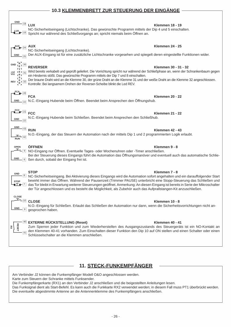
10.3 KLEMMENBRETT ZUR STEUERUNG DER EINGÄNGE
LUX Klemmen 18 - 19NC-Sicherheitseingang (Lichtschranke). Das gewünschte Programm mittels der Dip 4 und 5 einschalten.Spricht nur während des Schließvorgangs an; spricht niemals beim Öffnen an.
AUX Klemmen 24 - 25NC-Sicherheitseingang (Lichtschranke).Der AUX-Eingang ist für eine zusätzliche Lichtschranke vorgesehen und spiegelt deren eingestellte Funktionen wider.
REVERSER Klemmen 30 - 31 - 32Wird bereits verkabelt und geprüft geliefert. Die Vorrichtung spricht nur während der Schließphase an, wenn der Schrankenbaum gegen ein Hindernis stößt. Das gewünschte Programm mittels der Dip 7 und 8 einschalten.Der braune Draht wird an die Klemme 30, der grüne Draht an die Klemme 31 und der weiße Draht an die Klemme 32 angeschlossen.Kontrolle: Bei langsamem Drehen der Reverser-Scheibe blinkt die Led REV.
FCA Klemmen 20 - 22N.C.-Eingang Hubende beim Öffnen. Beendet beim Ansprechen den Öffnungshub.
FCC Klemmen 21 - 22N.C.-Eingang Hubende beim Schließen. Beendet beim Ansprechen den Schließhub.
RUN Klemmen 42 - 43N.O.-Eingang, der das Steuern der Automation nach der mittels Dip 1 und 2 programmierten Logik erlaubt.
ÖFFNEN Klemmen 9 - 8NO-Eingang nur Öffnen. Eventuelle Tages- oder Wochenuhren oder -Timer anschließen.Bei der Steuerung dieses Eingangs führt die Automation das Öffnungsmanöver und eventuell auch das automatische Schlie-ßen durch, sobald der Eingang frei ist.
STOP Klemmen 7 - 8NC-Sicherheitseingang. Bei Aktivierung dieses Eingangs wird die Automation sofort angehalten und ein darauffolgender Start bewirkt immer das Öffnen. Während der Pausenzeit (Trimmer PAUSE) unterbricht eine Stopp-Steuerung das Schließen und das Tor bleibt in Erwartung weiterer Steuerungen geöffnet. Anmerkung: An diesen Eingang ist bereits in Serie der Mikroschalter der Tür angeschlossen und es besteht die Möglichkeit, als Zubehör auch das Aufprallstangen-Kit anzuschließen.
CLOSE Klemmen 10 - 8N.O.-Eingang für Schließen. Erlaubt das Schließen der Automation nur dann, wenn die Sicherheitsvorrichtungen nicht an-gesprochen haben.
EXTERNE RÜCKSTELLUNG (Reset) Klemmen 40 - 41Zum Sperren jeder Funktion und zum Wiederherstellen des Ausgangszustands des Steuergeräts ist ein NO-Kontakt an den Klemmen 40-41 vorhanden. Zum Einschalten dieser Funktion den Dip 10 auf ON stellen und einen Schalter oder einen Schlüsselschalter an die Klemmen anschließen.
42
43
RUN
GND
GND8
7STOP
OPEN 9
8GND
REVERSER
GND
+12Vcc
REV
30
31
32
40R
X
41
RESET
18
19
GND
LUX
CLOSE10
8GND
11. STECK-FUNKEMPFÄNGERAm Verbinder J2 können die Funkempfänger Modell O&O angeschlossen werden.Karte zum Steuern der Schranke mittels Funksender.Die Funkempfängerkarte (RX1) an den Verbinder J2 anschließen und die beigestellten Anleitungen lesen.Das Funksignal dient als Start-Befehl. Es kann auch die Funkkarte RX2 verwendet werden; in diesem Fall muss PT1 überbrückt werden.Die eventuelle abgestimmte Antenne an die Antennenklemme des Funkempfängers anschließen.
24
25
AUX
GND
20
22
FCA
GND
21
22
FCC
GND
- 27 -
AUTOTEST
Bei Anwahl dieser Modalität führt das Aggregat eine Funktionskontrolle der Programme des Mikroprozessors und der angeschlossenen Peripheriegeräte durch Insbesondere: - Die Kontroll-Leds dienen zur Überprüfung der Anschlüsse außerhalb des Aggregats - Die Zustands-Leds dienen zur Überprüfung des internen Zustands des Aggregats
Prozedur: die DIP-Schalter 1,2 und 3 auf OFF stellen und die RESET-Taste betätigen
# Kontrolle: Alle Kontroll-Leds müssen gleichzeitig blinken, mit Ausnahme derer, die an Öffnerkontakte angeschlossen sind (die ständig leuchten) und der Leds REV und RES, die ausgeschaltet bleiben
Überprüfung: Bei Betätigung des Regeltrimmers TM1 (PAUSE) muß die Blinkfrequenz der Kontroll-Leds und die Folgegeschwindigkeit der Satus-Leds variieren. Diese Änderung zeigt an, daß der Mikroprozessor ordnungsgemäß funktioniert. Schaltet sich die Status-Led nicht ein, besteht eine Störung in der Steuereinheit.
ANWESENHEIT EINER PERSON
Die Betätigung der Schranke erfolgt durch ständiges Drücken der Tasten Öffnen oder SchließenWird die Taste Öffnen betätigt, so wird die Schranke angehoben und bei Ansprechen des Endschalters wird der Motor stillgelegtWird die Taste Schließen betätigt, so wird die Schranke gesenkt und bei Ansprechen des Endschalters wird der Motor stillgelegt.Die Photozelle spricht sowohl beim Öffnen als auch beim Schließen an: zur Wiederaufnahme der normalen Betriebs muß die betägtigte Steuertaste losgelassen und eine andere betätigt werden. Ausgeschlossen sind dabei Dip 3,4, und 5, der Betriebstimer, RX1 und die serielle LeitungDer Reverser führt das Programm aus, das durch DIP 7 und 8 festgelegt ist, mit Ausnahme der Konfi guration On/ON. In diesem Fall bleibt der Reverser stehen und öffnet bis FCA.Zur Wiederaufnahme der Steuerung muß ein Stop-Befehl gegeben werden.
HALBAUTOMATIK
Der Betrieb der Schranke erfolgt durch Impulsgabe (die zeitdauer muß nicht den zeitarbeit sein) durch die Tasten Start,Öffnen oder Schließen. Der Befehl wirkt auf eine Phase des Betriebsablaufs, die entweder Schließen oder Öffnen sein kannDer Schalter Dip 3 bestimmt, ob bei Loslassen der Taste das Schließen erfolgt oder nicht
AUTOMATIK
Der Betrieb der Schranke erfolgt durch Impulsgabe (die zeitdauer muß kürzer als der zeitarbeit sein) durch die Tasten Start,Öffnen oder Schließen.Beim Öffnen wartet die Schranke nach Erreichen des Endschalters (FCA) eine gewisse Zeit ab, die durch den Trimmer TM1 einstellbar ist, und geht dann automatisch zur Schließfunktion überDer Schalter Dip 3 bestimmt, ob bei Loslassen der Taste das Schließen erfolgt oder nicht, die Schalter Dip 4 und 5 bieten die Sequenz der Photozellen an.
SCHLIESSEN BEI LOSLASSEN DER STEUERTASTE
Diese Betriebsmodalität hat den Zweck, ein automatisches Schließen der Schranke zu erzielen, wenn das Fahrzeug den Bereich der Photozelle oder des Magnettasters verlassen hat (dies sind die Zubehörteile, die am Besten für diesen Einsatz geeignet sind).Dazu den Schließerkontakt des Magnettasters oder der Photozelle an die Klemmen 8-10 anschließen (Kontakt für Schließen) und den Schalter Dip 3 auf ON stellen.Die Anwesenheit eines Fahrzeugs am Magnettaster oder vor der Photozelle verursacht in diesem Fall nicht das sofortige Schließen, sondern es wird das Loslassen des entsprechenden Signals abgewartet.
12. BETRIEBSMODALITÄT
Fehlfunktion der Stop-Steuerung (Öffnerkontakt)Die Led STP ist normalerweise eingeschaltet. Das Ausschalten, falls nicht durch einen entsprechenden Befehl verursacht, bedeutet, daß der Kontakt für das Schließen unzulässigerweise offen ist. Solange dieser Kontakt nicht wieder in die Konfi guration als Öffnerkontakt gebracht wird, ist keine der Steuertasten betriebsfähig.
Fehlfunktion der Steuertasten Öffnen (Schließerkontakt), Schließen (Schließerkontakt) und Start (Schließerkontakt)Die entsprechenden Leds OPN, CLS und RUN sind normalerweise ausgeschaltet. Sollte einer dieser Kontakt Kurzschluß aufweisen, so bleibt die zugehörige Led eingeschaltet und alle anderen Steuertasten sind nicht betriebsfähig. Der Kontakt muß wieder als Schließer-kontakt konfi guriert werden, um den normalen Betrieb wieder herzustellen.
13. FEHLFUNKTIONEN DER STEUERUNGEN

- 28 -
ÌndiceCapìtulo Pàgina
1. INTRODUCCIÓN 5
2. CARACTERÍSTICAS PRINCIPALES 5
3. NOTA SOBRE LOS CABLES 5
4. CONJUNTO DE LAS PARTES 5
5. CARACTERÍSTICAS TÉCNICAS 5
6. ADVERTENCIAS 5
7. EQUIPO ELECTRONICO 6
8. CONFIGURACIÓN DE LOS DIP SWITCH 6
9. SEGURIDAD DE LA INSTALACIÓN 7
10. CONEXIONES Y FUNCIONES DE ENTRADAS Y SALIDAS 7 10.1 TABLERO DE BORNES DE POTENCIA 7 10.2 ABLERO DE BORNES DE SALIDA DE BAJA TENSIÓN 7 10.3 TABLERO DE BORNES DE CONTROL ENTRADAS 8
11. RECEPTOR VÍA RADIO ENCHUFABLE 8
12. MODALIDADES DE TRABAJO 9
13. AVERIAS EN LOS MANDOS 9

- 29 -
2. CARACTERÍSTICAS PRINCIPALES
ARX.246 ES
La central de control ARX.246 ha sido desarrollada para gestionar barriere monofase serie B e NIGHT&DAY.La notable cantidad de lógicas que se pueden seleccionar permite satisfacer incluso especiales condiciones operativas en las insta-laciones. El cumplimiento de los requisitos establecidos por las Directivas Europeas (89/336CEE,73/23CEE y sus modifi caciones sucesivas) demuestra el elevado estándar de calidad y de seguridad.
1. INTRODUCCIÓN
CENTRALITA ELECTRÓNICA
4. CONJUNTO DE LAS PARTES3. NOTA SOBRE LOS CABLES
Alimentación 230Vca ± 10% 50/60Hz (a petición 110Vca)Potencia máx. absorbida 1.200 WCarga máx. accesorios 500 mAPotencia máx. int. barra 20W (24V)Temp. de funcionamiento -20° / +70°Grado de protección IP54Dimensiones contenedor L200 x H275 x P130mm
Pos. Descripción N° cables Sección (mm2)
1 Linea monofàsica 2 + tierra 1,5 2 Caja de pulsadores 4 0,5 3 Selector de llave 3 0,5 4 Fotocél. receptor 4 0,5 5 Fotocél. transmisor 2 0,5 6 Espiras magnéticas enterradas 7 Señalizador intermitente 2 0,5 8 Receptor radio externo 4 0,5
5. CARACTERÍSTICAS TÉCNICAS
- Salida para señalizadores luminosos en la barra.- Salida para señalizador intermitente.- Preparada para el enchufe de los receptores vía radio con tarjeta O&O- Función de autotest entradas-salidas del microprocesador.
- Lógica de control por microprocesador - Pilotos que muestran el estado de las entradas- Tableros de bornes extraíbles - Entrada para dispositivo de seguridad "reverser" antiaplastamiento
6. ADVERTENCIAS
Se recomienda efectuar una instalación que prevea todos los accesorios necesarios para asegurar el funcionamiento según la normativa vigente, usando siempre dispositivos originales O&O.La utilización y la instalación de estos aparatos debe respetar rigurosamente las indicaciones ofrecidas por el fabricante que no puede ser considerado responsable por posibles daños derivados de un uso impropio o irracional.O&O declina cualquier responsabilidad por posibles inexactitudes contenidas en este folleto y se reserva el derecho de aportar las modifi caciones necesarias en cualquier momento sin ningún tipo de preaviso.

- 30 -
Después de un cambio de posición de los dip-switches se deberá pulsar la tecla de REINI-
CIALIZACION a fi n de almacenarla nueva confi guración.
ATTENCION
DIP FUNCTION
1 2 3 OPERATION OFF OFF OFF AUTOTESTOFF ON HOMBRE PRESENTEON OFF SEMIAUTOMATICOON ON AUTOMATICO
3 CIERRE MEDIANTE LIBERACION DE PULSADOROFF DESACTIVADOON ACTIVADO
4 5 FOTOCELULAOFF OFF En fase de CIERRE detiene y espera mandos con fotocelula libre.OFF ON En fase de CIERRE detiene; cierra de nuevo despues de 1.0 s. con fotocelula libre.ON OFF En fase de CIERRE reabre; cierra de nuevo despues de 1.0 s. con fotocelula libre. ON ON En fase de CIERRE reabre; cierra de nuevo despues de 5.0 s. con fotocelula libre.
6 CONTACTO USUARIOOFF Fotocélula interrumpida: contacto cortocircuitadoON Intervenciòn reverser: contacto cortocircuitado durante 500 mseg.
7 8 INVERSOROFF OFF EXCLUIDOOFF ON En fase de cierre detiene y espera mandos.ON OFF En fase de cierre detiene y abre de nuevo; luego espera mandos.ON ON En fase de cierre detiene y abre de nuevo; luego, despues de 5.0 s, cierra nuevamente.
9 LUCES DE BARRERAOFF intermitente en movimento.ON intermitente en movimento y luces encendidas con Barrera cerrada
10 RESET EXTERNOOFF ExcluidoON Incluido
DIP-SWITCH DEPROGRAMA
LGT LUCES DE BARRERAFWR MOTOR EN APERTURALIN MOTOR EN LINEAREW MOTOR EN CIERREUSR CONTACTO AUXILIAR
LUX FOTOCELULAAUX ENTRADA AUXILIARIAREV INVERSORFCA FINAL DE CARRERA DE APERTURAFCC FINAL DE CARRERA DE CIERRE RUN PULSADOR DE STARTOPN PULSADOR DE APERTURASTP PULSADOR DE STOPCLS PULSADOR DE CIERRERES RESET
REG. DEL TIEMPO DE PAUSA ( 0-60'')
MANDOS Y CONTROLES
8. CONFIGURACIÓN DE LOS DIP SWITCH
LED DE LINEA
LEDS DE STATUS
LEDS DE CONTROLES
7. EQUIPO ELECTRONICO
BORNES EXTRAIBLES LEDS DE
CONTROLES
TECLA DE START
TECLA DE REINICIALIZACION
REG. DEL TIEMPO DE PAUSE
MICROPROCESADOR
DIP-SW. DEPROGRAMA
TRANSFORMER
BANCO DE RELES
ESTATICOS
BANCO DE FUSIBLES
F1 TRS 250mA - TF2 SLR 250mA - FF3 ENG 6,3A - FF4 LGT 1A - FF5 12V 500mA - FF6 24V 1A - T
CONNECTORRADIO RECEPTOR
LEDS DE STATUS

- 31 -
10.1 TABLERO DE BORNES DE POTENCIA
9. SEGURIDAD DE LA INSTALACIÓN
Para que se alcance el grado de seguridad requerido por la normativa vigente, lean atentamente las siguientes prescripciones.
Realicen todas las conexiones en el tablero de bornes leyendo atentamente las indicaciones incluidas en este manual y respetando las normas generales y de buena técnica que regulan la ejecución de las instalaciones eléctricas.Preparar antes de la instalación un interruptor magnetotérmico omnipolar con una distancia de apertura de los contactos de un mínimo de 3 mm.Instalar, si no está previsto, un interruptor diferencial con umbral 30 mA.Comprobar la efi cacia de la instalación de toma de tierra y conectar a ésta todas las partes del automatismo provistas de borne o cable de tierra.Prever la presencia de al menos un dispositivo de señalación exterior, de tipo por semáforo o luz intermitente, acompañado de un cartel de indicación de peligro o de aviso.Aplicar todos los dispositivos de seguridad requeridos por el tipo de instalación considerando los riesgos que ésta puede causar.Separar en las canalizaciones las líneas de potencia (1,5 mm2 tamaño mínimo) de las de señal de baja tensión (0,5 mm2 tamaño mínimo).Hacer un puente en las entradas N.C. no utilizadas.Poner en serie los eventuales contactos a conectar en serie en la misma entrada N.C.Poner en paralelo las entradas conectadas a la misma entrada N.A.
1)
2)3)4)5)
6)7)8)9)10)
LÍNEA 230V bornes 1 - 2 (230V)Alimentación a 230 V 50/60 Hz con protección interna de movimiento y fusible (5x20) de 6,3A.Conectar la fase y el neutro como se muestra en la serigrafía, mientras que la tierra se conecta a los bornes faston EARTH. Utilizar un cable de tipo H05VV-F 2x1,5+T min.
LUZ INTERMITENTE: LUZ AMARILLA a 230V 100W max bornes 11 - 12 (SLR)Unidad para la señalización de automatismo en acción; modelo SLR.Conectar los bornes 11 y 12 de la centralita respectivamente con los bornes N y F del intermitente.La salida está protegida por fusible de 250 mA (F2). N.B.: utilizar solamente lámparas de 230Vca máx. 40W.
MOTOR bornes 4 - 5 - 6 (ENGINE)Salida motor 230V: MARRÓN-4; AZUL-5; NEGRO-6.El cable de tierra se debe conectar con los bornes EARTH.
10. CONEXIONES Y FUNCIONES DE ENTRADAS Y SALIDAS
SLR
11
12
M
AP
C
CH
4
5
6
230 V ~
N
P
1
2
44
USER
45
24 V14
15
24 V17
16
LIGHTS
34
35
USER bornes 44 - 45Contacto para uso externo que señala cada actuación de la fotocélula.El funcionamiento está gobernado por programa a través del Dip 6. Capacidad del contacto a 230Vca: 4 AN.B.: En las versiones DD3 la salida se utiliza para mandar el bloqueo eléctrico
LIGHTS bornes 34 - 35Se pone a disposición una salida de 24Vca para la alimentación de señalizadores luminosos en la barra.Conectar los cables de las lámparas (3x24Vca 5W o 6x24Vca 3W), en paralelo con los bornes 34 - 35.La salida es regulable por programa a través del Dip 9. Control: al encendido del LED LGT tienen que encenderse todas las lámparas.La salida está activa contextualmente a la compra de una barrera con luces o bien sucesivamente después de comprar el accesorio "predisposición para luces".
24 V bornes 14 - 15Salida de 24Vca para alimentar accesorios de seguridad y mando como fotocélulas o receptores radio.
24 V bornes 17 - 16Salida de 24Vca para alimentar accesorios de seguridad y mando como fotocélulas o receptores radio.
10.2 TABLERO DE BORNES DE SALIDA DE BAJA TENSIÓN

- 32 -
LUX bornes 18 - 19Entrada NC de seguridad (fotocélula). Activar el programa que se desea por medio de los Dip 4 y 5. Actúa solamente en fase de cierre; en apertura no actúa nunca.
AUX bornes 24 - 25Entrada NC de seguridad (fotocélula).La entrada AUX está prevista para una fotocélula suplementaria y refl eja sus funciones confi guradas.
REVERSER bornes 30 - 31 - 32Se suministra ya cableado y ensayado. El dispositivo actúa solamente en la fase de cierre cuando la barra choca contra un obstáculo. Activar el programa que se desea por medio de los Dip 7 y 8.El hilo marrón se debe conectar con el borne 30, el verde con el borne 31, el blanco con él 32.Control: girando despacio el disco del reverser parpadea el LED REV.
FCA bornes 20 - 22Entrada N.C. de fi nal de carrera en apertura. Cuando se activa termina la carrera de apertura.
FCC bornes 21 - 22Entrada N.C. de fi nal de carrera en cierre. Cuando se activa termina la carrera de cierre.
RUN bornes 42 - 43Entrada N.A. que permite mandar la automatización según la lógica programada a través de los Dip 1 y 2.
ABRE bornes 9 - 8Entrada N.A. sólo de abertura. Conectar aquí eventuales relojes o timer diarios o semanales.Manteniendo controlada esta entrada el automatismo efectuará la maniobra de apertura y efectuará el eventual reenganche automático sólo cuando se haya liberado la entrada.
STOP bornes 7 - 8Entrada N.C. de seguridad. Cuando se activa detiene inmediatamente la automatización y un sucesivo start provoca siempre una re-apertura. Durante el tiempo de pausa (trimmer PAUSE) un mando de Stop elimina el re-cierre automático dejando la barrera abierta a la espera de mandos. N.B.: Con esta entrada ya está conectado de serie el microinterruptor de la puerta y es posible, como accesorio, conectar también el kit barra fractura.
CIERRA bornes 10 - 8Entrada N.A. de cierre. Permite cerrar el automatismo sólo si los dispositivos de seguridad no están ocupados
RESET EXTERNO bornes 40 - 41Para tener la posibilidad de bloquear todas las funciones y poner de nuevo en las condiciones iniciales la centralita, está previsto un contacto NA en los bornes 40-41: para activar la función se debe poner en ON el Dip 10 y conectar con los bornes un interruptor o un selector con llave.
10.3 TABLERO DE BORNES DE CONTROL ENTRADAS
42
43RUN
GND
GND8
7STOP
OPEN 9
8GND
REVERSER
GND
+12Vcc
REV
30
31
32
40
RX
41
RESET
18
19
GND
LUX
CLOSE10
8GND
11. RECEPTOR VÍA RADIO ENCHUFABLEEn el conector J2 es posible conectar los receptores radio modelo O&O.Tarjeta para mandar la barrera a través de transmisores radio.Enchufar la tarjeta radioreceptora (RX1) en el conector J2 y leer las instrucciones adjuntas.La señal radio actúa como mando de Start. Es posible también utilizar la tarjeta radio RX2; en tal caso se debe puentear PT1.Conectar la eventual antena afi nada al borne de antena de la receptora radio.
24
25
AUX
GND
20
22
FCA
GND
21
22
FCC
GND

- 33 -
AUTOTEST
Disponiendo esta modalidad, se obtiene una prueba de funcionamiento de la centralita, prueba que permitirá controlar los programasinternos del microprocesador y las periféricas a él conectadas.
En particular: -los leds de control sirven para verifi car el correcto funcionamiento de las conexiones externas de la centralita; -los leds de status controlan el estado interno de la centralita.
Procedimiento: Disponer los dips 1, 2 y 3 en OFF. Suministrar tensión a la centralita.
# Control: Deberán centellear de modo simultáneo todos los leds de control, excepto aquellos relativos a los contactos NC, que deberán permanecer encendidos, y los leds REV y RES, que deberán permanecer apagados.
Por su parte, los leds de status deberán encenderse de modo secuencial.
Verifi cación: Operando con el trimmer de regulación TM1 (PAUSE) deberá variar la frecuencia de centelleo de los leds de control y la velocidad secuencial de encendido de los leds de status: este comportamiento indica que el microprocesador está funcionando correctamente.
La falta de encendido de uno o más de un led de status indica que se ha verifi cado una avería en la centralita. La falta de centelleo de uno de los leds de control indica que hay un problema en la conexión de la unidad externa
correspondiente.
HOMBRE PRESENTE
El funcionamiento de la barrera se obtiene oprimiendo de modo continuado el pulsador de apertura o de cierre.Manteniendo oprimido apertura, la barrera de alza pero al llegar al fi nal de carrera, en todo caso el motor se detiene.Manteniendo oprimido cierre, la barra desciende, pero al llegar al fi nal de carrera, en todo caso el motor se detiene.La fotocélula interviene tanto en fase de apertura como de cierre; para restablecer el funcionamiento normal se deberá dejar el mando interrumpido y enviar uno nuevo. Quedan excluidos los dips 3, 4 y 5, el temporizador de trabajo, RX1 y serial.El inversor sigue el programa seleccionado mediante los dips 7 y 8 excepto en la confi guración ON / ON, con la cual detiene y abre nuevamente hasta fi nal de carrera de apertura.Para reactivar los mandos será necesario enviar un mando de stop.
SEMIAUTOMATICO
El funcionamiento de la barrera se produce por impulsos (de duración inferiore al tiempo de trabajo) sobre los pulsadores de start, aper-tura y cierre. El mando operará una fase del ciclo de funcionamiento, que podrá ser o de apertura o de cierre.El dip 3 activa o no activa el cierre mediante liberación de pulsador o abandono de la posición.
AUTOMATICO
El funcionamiento de la barrera se produce por impulsos (de duración inferiore al tiempo de trabajo) sobre el pulsador de start, apertura o cierre. En relación a una operación de apertura, una vez que llega al fi nal de carrera (FCA), la barrera se detiene por un cierto lapso - ya predispuesto mediante el trimmer TM1 - después de lo cual se cerrará nuevamente de modo automático.El dip 3 activa o no activa el cierre mediante liberación de pulsador. Los dips 4 y 5 proponen las secuencias de fotocélula.
CIERRE MEDIANTE LIBERACION DE PULSADOR O ABANDON DE LA POSICION
Modalidad de funcionamiento estudiada a fi n de obtener el cierre automático de la barrera sólo una vez que el vehículo ha abandonado la zona cubierta por la fotocélula o el nivelador magnético (accesorios más adecuados para este fi n).Conectar el contacto NA del detector o de la fotocélula en los bornes 8-10 (contacto de cierre) y disponer el dip 3 en ON.La presencia del vehículo en zona controlada por el detector o la fotocélula no provoca el cierre inmediato; será necesario esperar el envío de la respectiva señal.
12. MODALIDADES DE TRABAJO
Avería en el mando de STOP (NC)En condiciones normales el led STP permanece siempre encendido; el apagamiento de este led sin ningún mando que lo justifi que indica que el contacto de cierre se encuentra erróneamente abierto. En este caso no será posible operar con ningún mando mientras dicho contacto no sea predispuesto en confi guración de NC.
Avería en el mando de apertura (NA), cierre (NA) o start (NA)En condiciones normales los respectivos leds OPN, CLS y RUN permanecen apagados. En caso de que uno de estos contactos entre erróneamente en cortocircuito, el respectivo led queda encendido y los restantes mandos no operan. Se deberá predisponer nuevamente la confi guración NA a fi n de restablecer el funcionamiento normal.
13. AVERIAS EN LOS MANDOS

cod.
035
162
ve
r. 5
25
/08/
10
MA
DE
IN IT
ALY
Versione Version Version Version Versión
ARX.246
Riferimenti References Références Bezugnahmen Referencias
Note Notes Remarques Anmerkungen Notas
Rivenditore/Resaler/Revendeur/Wiederverkäufer/Revendedor
O&O srlVia Europa 2 - 42015 CORREGGIO (RE) - ITALY
Phone.: 39 0522 740111 (r.a. 5 l.) - Fax 0522 631290Internet: www.oeo.it - E-mail: [email protected]
Utente/User/Utilisateur/Verbraucher/Usuario
Installatore/Installer/Installateur/Installateur/Instalador


![KLIC-DD3 · KLIC-DD3 Pasarela KNX –Daikin para unidades de A/A Daikin gama doméstica. O ZCL-DD3dsñkmfroi Versión del programa de aplicación: [1.0] Edición del manual: [1.0]_a](https://img.dokumen.tips/doc/110x75/5e73fd4249e52602834e98e2/klic-dd3-klic-dd3-pasarela-knx-adaikin-para-unidades-de-aa-daikin-gama-domstica.jpg)