Embed Size (px)
Citation preview


www.adeept.com
Content
About Arduino .......................................................................................................................... - 1 -
Lesson 1 Blinking LED ........................................................................................................... - 2 -
Lesson 2 Controlling an LED with a button .................................................................... - 7 -
Lesson 3 LED Flowing Lights ............................................................................................ - 13 -
Lesson 4 Breathing LED ..................................................................................................... - 17 -
Lesson 5 Potentiometer ...................................................................................................... - 21 -
Lesson 6 ActiveBuzzer ........................................................................................................ - 25 -
Lesson 7 Relay module ....................................................................................................... - 30 -
Lesson 8 Controlling a RGB LED by PWM ..................................................................... - 34 -
Lesson 9 TiltSwitch .............................................................................................................. - 38 -
Lesson 10 RotaryEncoder .................................................................................................. - 41 -
Lesson 11 LCD1602 ............................................................................................................. - 46 -
Lesson 12 Photoresistor ..................................................................................................... - 51 -
Lesson 13 Using a thermistor to measure the temperature .................................. - 54 -
Lesson 14 Temperature alarm ......................................................................................... - 58 -
Lesson 15 7-Segment ......................................................................................................... - 60 -
Lesson 16 Serial Port........................................................................................................... - 64 -
Lesson 17 DC Motor Fan ................................................................................................... - 70 -
Lesson 18 Controlling Servo motor ................................................................................ - 75 -
www.adeept.com
Lesson 19 UltrasonicDistanceSensor .............................................................................. - 78 -
Lesson 20 Ultrasonic control Servo ................................................................................ - 82 -
Lesson 21 Combined LED Experiment ........................................................................... - 84 -
Lesson 22 Ultrasonic Fan ................................................................................................... - 86 -
Lesson 23 Reversing Radar ............................................................................................... - 88 -

www.adeept.com
- 1 -
About Arduino
What is Arduino?
Arduino is an open-source electronics platform based on easy-to-use hardware and software. It's intended for anyone making interactive projects.
ARDUINO BOARD
Arduino senses the environment by receiving inputs from many sensors, and affects its surroundings by controlling lights, motors, and other actuators.
ARDUINO SOFTWARE
You can tell your Arduino what to do by writing code in the Arduino programming language and using the Arduino development environment.
Before the development of Arduino program, the first thing you have to do is to install Arduino IDE software. The software provides you with the basic development environment that is required for developing Arduino program. You need the following URL to download Arduino IDE: http://www.arduino.cc/en/Main/Software
For different operating system platforms, the way of using Arduino IDE is different. Please refer to the following links: Windows User:http://www.arduino.cc/en/Guide/Windows Mac OS X User:http://www.arduino.cc/en/Guide/MacOSX Linux User:http://playground.arduino.cc/Learning/Linux
For more detailed information about Arduino IDE, please refer to the following
https://youtu.be/BsTDVB8B240

www.adeept.com
- 2 -
Lesson 1 Blinking LED Overview
In this tutorial, we will start the journey of learning Arduino UNO. In the first lesson, we will learn how to make a LED blinking.
Requirement
- 1* Arduino UNO - 1* USB Cable - 1* 220Ω Resistor - 1* LED - 1* Breadboard - 2* Jumper Wires
Principle
In this lesson, we will program the Arduino's GPIO output high(+5V) and low level(0V), and then make the LED which is connected to the Arduino’s GPIO flicker with a certain frequency.
1. What is the LED?
The LED is the abbreviation of light emitting diode. It is usually made of gallium arsenide, gallium phosphide semiconductor materials. The LED has two electrodes, a positive electrode and a negative electrode, it will light only when a forward current passes, and it can be red, blue, green or yellow light, etc. The color of light depends on the materials it was made.
In general, the drive current for LED is 5-20mA. Therefore, in reality it usually needs an extra resistor for current limitation so as to protect the LED. 2. What is the resistor?
The main function of the resistor is to limit current. In the circuit, the character ‘R’ represents resistor, and the unit of resistor is ohm(Ω).
The band resistor is used in this experiment. A band resistor is one whose surface is coated with some particular color through which the resistance can be identified directly.

www.adeept.com
- 3 -
There are two methods for connecting LED to Arduino’s GPIO:
①
As shown in the schematic diagram above, the anode of LED is connected to Arduino’s GPIO via a resistor, and the cathode of LED is connected to the ground(GND). When the GPIO output high level, the LED is on; when the GPIO output low level, the LED is off.
The size of the current-limiting resistor is calculated as follows: 5~20mA current is required to make an LED on, and the out put voltage of the Arduino UNO’s GPIO is 5V, so we can get the resistance:
R = U / I = 5V / (5~20mA) = 250Ω~1KΩ
Since the LED has a certain resistance, thus we choose a 220ohm resistor.
②
As shown in the schematic diagram above, the anode of LED is connected to VCC(+5V), and the cathode of LED is connected to the Arduino’s GPIO. When the GPIO output low level, the LED is on; when the GPIO output high level, the LED is off.
The experiment is based on method ①, we select Arduino's D8 pin to control the LED. When the Arduino’s D8 pin is programmed to output high level, then

www.adeept.com
- 4 -
the LED will be on, next delay for the amount of time, and then programmed the D8 pin to low level to make the LED off. Continue to perform the above process, you can get a blinking LED.
3. Key functions:
● setup()
The setup() function is called when a sketch starts. Use it to initialize variables, pin modes, start using libraries, etc. The setup function will only run once, after each powerup or reset of the Arduino board.
●loop()
After creating a setup() function, which initializes and sets the initial values, the loop() function does precisely what its name suggests, and loops consecutively, allowing your program to change and respond. Use it to actively control the Arduino board.
●pinMode()
Configures the specified pin to behave either as an input or an output.
As of Arduino 1.0.1, it is possible to enable the internal pullup resistors with the mode INPUT_PULLUP. Additionally, the INPUT mode explicitly disables the internal pullups.
●digitalWrite()
Write a HIGH or a LOW value to a digital pin.
If the pin has been configured as an OUTPUT with pinMode(), its voltage will be set to the corresponding value: 5V (or 3.3V on 3.3V boards) for HIGH, 0V (ground) for LOW.
If the pin is configured as an INPUT, digitalWrite() will enable (HIGH) or disable (LOW) the internal pullup on the input pin. It is recommended to set the pinMode() to INPUT_PULLUP to enable the internal pull-up resistor.
●delay()
Pauses the program for the amount of time (in miliseconds) specified as parameter. (There are 1000 milliseconds in a second.)

www.adeept.com
- 5 -
Procedures
1. Build the circuit
2. Program /***********************************************************
File name: 01_blinkingLed.ino
Description: Lit LED, let LED blinks.
Website: www.adeept.com
E-mail: [email protected]
Author: Ryan
Date:2018/01/01
***********************************************************/
int ledPin=8; //definition digital 8 pins as pin to control the LED
void setup()
{
pinMode(ledPin,OUTPUT); //Set the digital 8 port mode, OUTPUT:
Output mode
}
void loop()
{
digitalWrite(ledPin,HIGH); //HIGH is set to about 5V PIN8
delay(1000); //Set the delay time, 1000 = 1S
digitalWrite(ledPin,LOW); //LOW is set to about 5V PIN8
delay(1000); //Set the delay time, 1000 = 1S
}

www.adeept.com
- 6 -
3. Compile the program and upload to Arduino UNO board Now, you can see the LED is blinking.
www.adeept.com
- 7 -
Lesson 2 Controlling an LED with a button Overview
In this lesson, we will learn how to detect the state of a button, and then toggle the state of LED based on the state of the button.
Requirement
- 1* Arduino UNO - 1* USB cable - 1* Button - 1* LED - 1* 10KΩ Resistor - 1* 220Ω Resistor - 1* Breadboard - Several Jumper wires
Principle
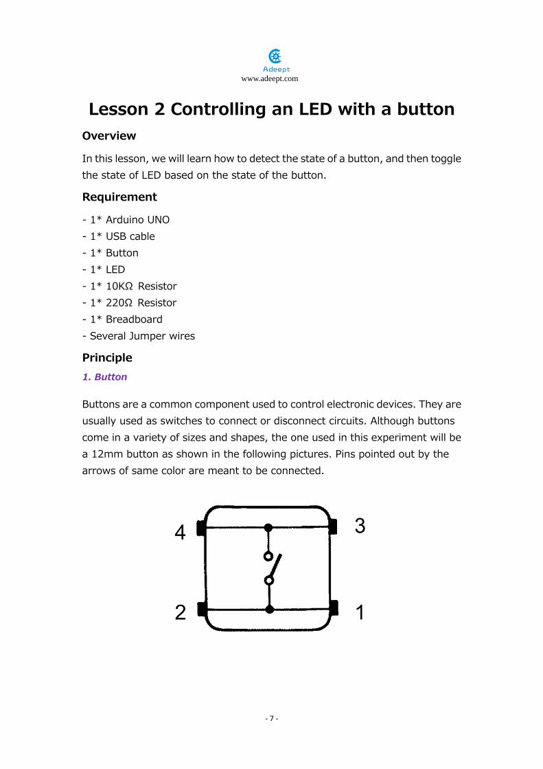
1. Button
Buttons are a common component used to control electronic devices. They are usually used as switches to connect or disconnect circuits. Although buttons come in a variety of sizes and shapes, the one used in this experiment will be a 12mm button as shown in the following pictures. Pins pointed out by the arrows of same color are meant to be connected.
www.adeept.com
- 8 -
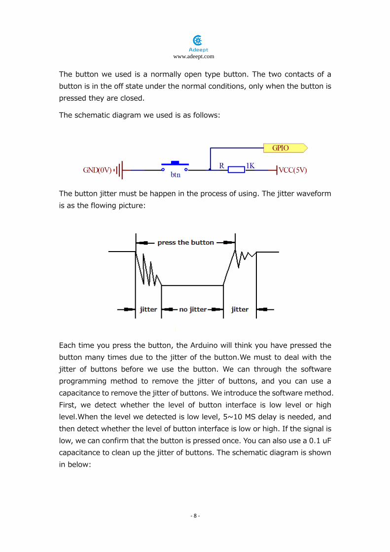
The button we used is a normally open type button. The two contacts of a button is in the off state under the normal conditions, only when the button is pressed they are closed.
The schematic diagram we used is as follows:
The button jitter must be happen in the process of using. The jitter waveform is as the flowing picture:
Each time you press the button, the Arduino will think you have pressed the button many times due to the jitter of the button.We must to deal with the jitter of buttons before we use the button. We can through the software programming method to remove the jitter of buttons, and you can use a capacitance to remove the jitter of buttons. We introduce the software method. First, we detect whether the level of button interface is low level or high level.When the level we detected is low level, 5~10 MS delay is needed, and then detect whether the level of button interface is low or high. If the signal is low, we can confirm that the button is pressed once. You can also use a 0.1 uF capacitance to clean up the jitter of buttons. The schematic diagram is shown in below:

www.adeept.com
- 9 -
2. interrupt
Hardware interrupts were introduced as a way to reduce wasting the processor's valuable time in polling loops, waiting for external events. They may be implemented in hardware as a distinct system with control lines, or they may be integrated into the memory subsystem.
3. Key functions:
●attachInterrupt(interrupt, ISR, mode)
Specifies a named Interrupt Service Routine (ISR) to call when an interrupt occurs. Replaces any previous function that was attached to the interrupt. Most Arduino boards have two external interrupts: numbers 0 (on digital pin 2) and 1 (on digital pin 3).
Generally, an ISR should be as short and fast as possible. If your sketch uses multiple ISRs, only one can run at a time, other interrupts will be ignored (turned off) until the current one is finished. as delay() and millis() both rely on interrupts, they will not work while an ISR is running. delayMicroseconds(), which does not rely on interrupts, will work as expected.
Syntax attachInterrupt(pin, ISR, mode)
Parameters pin: the pin number ISR: the ISR will be called when the interrupt occurs; this function must take no parameters and return nothing. This function is sometimes referred to as an interrupt service routine. mode: defines when the interrupt should be triggered. Four contstants are predefined as valid values:
-LOW to trigger the interrupt whenever the pin is low, -CHANGE to trigger the interrupt whenever the pin changes value -RISING to trigger when the pin goes from low to high,

www.adeept.com
- 10 -
-FALLING for when the pin goes from high to low. ●digitalRead()
Reads the value from a specified digital pin, either HIGH or LOW. Syntax digitalRead(pin) Parameters pin: the number of the digital pin you want to read (int) Returns HIGH or LOW ●delayMicroseconds(us)
Pauses the program for the amount of time (in microseconds) specified as parameter. There are a thousand microseconds in a millisecond, and a million microseconds in a second.
Currently, the largest value that will produce an accurate delay is 16383. This could change in future Arduino releases. For delays longer than a few thousand microseconds, you should use delay() instead.
Syntax delayMicroseconds(us) Parameters us: the number of microseconds to pause (unsigned int) Returns None

www.adeept.com
- 11 -
Procedures
1. Build the circuit
2.Program
Code position: AdeeptUltimateSensorKitForUNOR3\02_btnAndLed1 AdeeptUltimateSensorKitForUNOR3\02_btnAndLed2
02_btnAndLed1:by detecting the button ports and level changes circularly to control the light 02_btnAndLed2: by breaking off to detect the button ports and level changes to control the light
3. Compile the program and upload to Arduino UNO board When you press the button, you can see the state of the LED will be toggled. (ON->OFF,OFF->ON).

www.adeept.com
- 12 -
Summary
Through this lesson, you should have learned how to use the Arduino UNO
detects an external button state, and then toggle the state of LED relying on
the state of the

www.adeept.com
- 13 -
Lesson 3 LED Flowing Lights In the first class, we have learned how to make an LED blink by programming the Arduino. Today, we will use the Arduino to control 8 LEDs, so that 8 LEDs showing the result of flowing.
Requirement
- 1* Arduino UNO - 1* USB cable - 8* LED - 8* 220Ω Resistor - 1* Breadboard - Several Jumper wires
Principle
The principle of this experiment is very simple. It is very similar with the first class.
Key function:
●for statements
The for statement is used to repeat a block of statements enclosed in curly braces. An increment counter is usually used to increment and terminate the loop. The for statement is useful for any repetitive operation, and is often used in combination with arrays to operate on collections of data/pins.
There are three parts to the for loop header:
for (initialization; condition; increment) {
//statement(s); }

www.adeept.com
- 14 -
The initialization happens first and exactly once. Each time through the loop, the condition is tested; if it's true, the statement block, and the increment is executed, then the condition is tested again. When the condition becomes false, the loop ends.
Procedures
1. Build the circuit
www.adeept.com
- 15 -
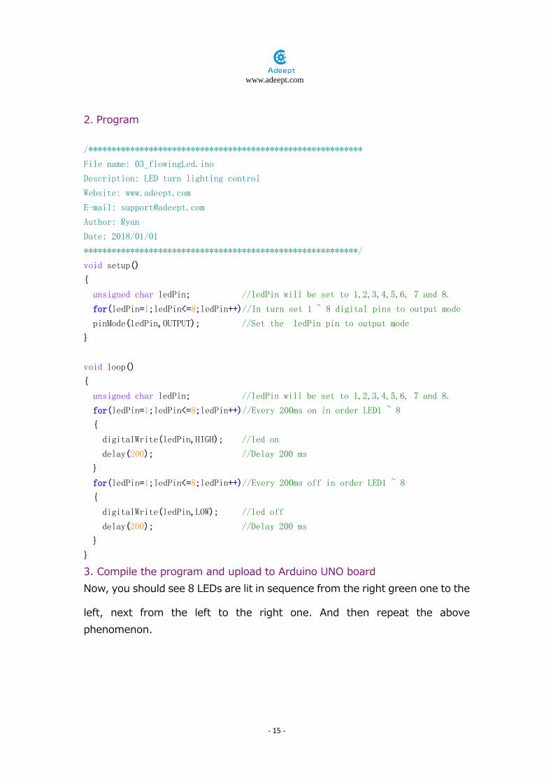
2. Program /***********************************************************
File name: 03_flowingLed.ino
Description: LED turn lighting control
Website: www.adeept.com
E-mail: [email protected]
Author: Ryan
Date: 2018/01/01
***********************************************************/ void setup()
{
unsigned char ledPin; //ledPin will be set to 1,2,3,4,5,6, 7 and 8.
for(ledPin=1;ledPin<=8;ledPin++)//In turn set 1 ~ 8 digital pins to output mode
pinMode(ledPin,OUTPUT); //Set the ledPin pin to output mode
}
void loop()
{
unsigned char ledPin; //ledPin will be set to 1,2,3,4,5,6, 7 and 8.
for(ledPin=1;ledPin<=8;ledPin++)//Every 200ms on in order LED1 ~ 8
{
digitalWrite(ledPin,HIGH); //led on
delay(200); //Delay 200 ms
}
for(ledPin=1;ledPin<=8;ledPin++)//Every 200ms off in order LED1 ~ 8
{
digitalWrite(ledPin,LOW); //led off
delay(200); //Delay 200 ms
}
} 3. Compile the program and upload to Arduino UNO board Now, you should see 8 LEDs are lit in sequence from the right green one to the
left, next from the left to the right one. And then repeat the above phenomenon.

www.adeept.com
- 16 -
Summary
Through this simple and fun experiment, we have learned more skilled programming about the Arduino. In addition, you can also modify the circuit and code we provided to achieve even more dazzling effect.

www.adeept.com
- 17 -
Lesson 4 Breathing LED Overview
In this lesson, we will learn how to program the Arduino to generate PWM signal. And use the PWM square-wave signal control an LED gradually becomes brighter and then gradually becomes dark like the animal’s breathing.
Requirement
- 1* Arduino UNO - 1* USB cable - 1* LED - 1* 220Ω Resistor - 1* Breadboard - Several Jumper wires
Principle
Pulse Width Modulation, or PWM, is a technique for getting analog results with digital means. Digital control is used to create a square wave, a signal switched between on and off. This on-off pattern can simulate voltages in between full on (5 Volts) and off (0 Volts) by changing the portion of the time the signal spends on versus the time that the signal spends off. The duration of "on time" is called the pulse width. To get varying analog values, you change, or modulate, that pulse width. If you repeat this on-off pattern fast enough with an LED for example, the result is as if the signal is a steady voltage between 0 and 5v controlling the brightness of the LED.
In the graphic below, the green lines represent a regular time period. This duration or period is the inverse of the PWM frequency. In other words, with Arduino's PWM frequency at about 500Hz, the green lines would measure 2 milliseconds each. A call to analogWrite() is on a scale of 0 - 255, such that analogWrite(255) requests a 100% duty cycle (always on), and analogWrite(127) is a 50% duty cycle (on half the time) for example.

www.adeept.com
- 18 -
Key function:
●analogWrite()
Writes an analog value (PWM wave) to a pin. Can be used to light an LED at varying brightnesses or drive a motor at various speeds. After a call to analogWrite(), the pin will generate a steady square wave of the specified duty cycle until the next call to analogWrite() (or a call to digitalRead() or digitalWrite() on the same pin). You do not need to call pinMode() to set the pin as an output before calling analogWrite().
Syntax analogWrite(pin, value) Parameters pin: the pin to write to. value: the duty cycle: between 0 (always off) and 255 (always on). Returns nothing

www.adeept.com
- 19 -
Procedures
1. Build the circuit
2. Program /***********************************************************
File name: 04_breathingLed.ino
Description: PWM control the LED gradually from dark to
brighter, then from brighter to dark
Website: www.adeept.com
E-mail: [email protected]
Author:Ryan
Date: 2018/01/01
***********************************************************/
int ledpin=11; //definition digital 11 pins as pin to control the LED
void setup ()
{
pinMode(ledpin,OUTPUT); //Set digital 11 port mode, the OUTPUT for the output
}
void loop()
{

www.adeept.com
- 20 -
for (int a=0; a<=255;a++) //Loop, PWM control of LED brightness increase
{
analogWrite(ledpin,a); //PWM output value a (0~255)
delay(15); //The duration of the current brightness level. 15ms
}
for (int a=255; a>=0;a--) //Loop, PWM control of LED brightness Reduced
{
analogWrite(ledpin,a); //PWM output value a (255~0)
delay(15); //The duration of the current brightness level. 15ms
}
delay(100); //100ms delay
} 3. Compile the program and upload to Arduino UNO board. Now, you should see the LED gradually from dark to brighter, and then from brighter to dark, continuing to repeat the process, its rhythm like the animal's breathing.
Summary
By learning this lesson, I believe that you have understood the basic principles of the PWM, and mastered the PWM programming on the Arduino platform.

www.adeept.com
- 21 -
Lesson 5 Control LED Brightness by
Potentiometer Overview
In this lesson, we'll learn how to control an LED by potentiometer.
Requirement
- 1* Arduino UNO - 1* USB Cable - 1* 220Ω Resistor - 1* LED - 1* potentiometer - 1* Breadboard - 5* Jumper Wires
Principle
In this experiment, a B10k potentiometer is used to control LED brightness by PWM signals.
1. What is a potentiometer?
Potentiometer is a resistor element with 3 terminals whose resistance can be changed based on certain rules. It is usually composed of a resistive element and a moveable electric brush. When the brush moves along the element, at the terminal a resistance or voltage is generated relative to the distance it moved.
2. key funcation ●setup()
The setup() function is called when a sketch starts. Use it to initialize variables, pin modes, start using libraries, etc. The setup function will only run once, after each powerup or reset of the Arduino board.

www.adeept.com
- 22 -
●loop() After creating a setup() function, which initializes and sets the initial values, the loop() function does precisely what its name suggests, and loops consecutively, allowing your program to change and respond. Use it to actively control the Arduino board. ●pinMode()
Configures the specified pin to behave either as an input or an output.
As of Arduino 1.0.1, it is possible to enable the internal pullup resistors with the mode INPUT_PULLUP. Additionally, the INPUT mode explicitly disables the internal pullups.
Procedures
1. Build the circuit

www.adeept.com
- 23 -
2.Program /***********************************************************
File name: 05_potentiometer.ino
Description:The rotating potentiometer can see the brightness of the LED changing.
Website: www.adeept.com
E-mail: [email protected]
Author: Ryan
Date: 2018/01/01
***********************************************************/
void setup()
{
pinMode(11,OUTPUT); //Set PWM outlet 11
}
void loop()
{
int n = analogRead(A0); //Read the value of the A0 simulation port (0-5v
corresponding to 0-1204 value)
analogWrite(11,n/4); //The maximum value of PWM is 255, so the value of the
simulated port is divided by 4.
}
3. Compile the program and upload to Arduino UNO board Now, you turn the potentiometer and you can see the change in the brightness of the LED.

www.adeept.com
- 24 -
Summary
After this lesson, you should have learnt using a Potentiometer to change the illuminance of an LED light. Later on you can use it to control more devices similarly.

www.adeept.com
- 25 -
Lesson 6 Active Buzzer Overview
In this lesson, we will learn how to program the Arduino to make an active buzzer sound.
Requirement
- 1* Arduino UNO - 1* USB cable - 1* Active buzzer - 1* 1 kΩ Resistor - 1* NPN Transistor (S8050) - 1* Breadboard - Several Jumper Wires
Principle
A buzzer or beeper is an audio signaling device. As a type of electronic buzzer with integrated structure, which use DC power supply, are widely used in computers, printers, photocopiers, alarms, electronic toys, automotive electronic equipments, telephones, timers and other electronic products for voice devices. Buzzers can be categorized as active and passive buzzers (See the following pictures).
Active buzzer Passive buzzer
When you place the pins of buzzers upward, you can see that two buzzers are different, the buzzer that green circuit board exposed is the passive buzzer.

www.adeept.com
- 26 -
In this study, the buzzer we used is active buzzer. Active buzzer will sound as long as the power supply. We can program to make the Arduino output alternating high and low level, so that the buzzer sounds.
A slightly larger current is needed to make a buzzer sound. However, the output current of Arduino’s GPIO is weak, so we need a transistor to drive the buzzer.
The main function of transistor is blowing up the voltage or current. The transistor can also be used to control the circuit conduction or deadline. And the transistor is divided into two kinds, one kind is NPN, for instance, the S8050 we provided; another kind is PNP transistor such as the S8550 we provided. The transistor we used is as shown in below:
There are two driving circuit for the buzzer:
Figure1 Figure2
www.adeept.com
- 27 -
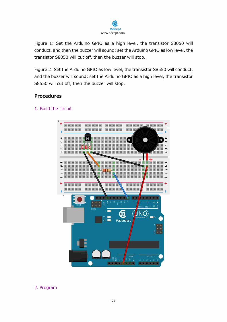
Figure 1: Set the Arduino GPIO as a high level, the transistor S8050 will conduct, and then the buzzer will sound; set the Arduino GPIO as low level, the transistor S8050 will cut off, then the buzzer will stop.
Figure 2: Set the Arduino GPIO as low level, the transistor S8550 will conduct, and the buzzer will sound; set the Arduino GPIO as a high level, the transistor S8550 will cut off, then the buzzer will stop.
Procedures
1. Build the circuit
2. Program

www.adeept.com
- 28 -
/***********************************************************
File name: 06_activeBuzzer.ino
Description: Arduino uno Continuous beeps control buzzer.
Website: www.adeept.com
E-mail: [email protected]
Author: Ryan
Date: 2018/01/01
***********************************************************/
int buzzerPin=8; //definition digital 8 pins as pin to control the buzzer
void setup()
{
pinMode(buzzerPin,OUTPUT); //Set digital 8 port mode, the OUTPUT for the output
}
void loop()
{
digitalWrite(buzzerPin,HIGH); //Set PIN 8 feet as HIGH = 5 v
delay(2000); //Set the delay time,2000ms
digitalWrite(buzzerPin,LOW); //Set PIN 8 feet for LOW = 0 v
delay(2000); //Set the delay time,2000ms
}
3. Compile the program and upload to Arduino UNO board
Now, you should be able to hear the sound of the buzzer.

www.adeept.com
- 29 -
Summary
By learning this lesson, we have mastered the basic principle of the buzzer and the transistor. We also learned how to program the Arduino and then control the buzzer. I hope you can use what you have learned in this lesson to do some interesting things.

www.adeept.com
- 30 -
Lesson 7 Controlling Relay Overview
In this lesson, we will learn how to control a relay to cut off or connect a circuit.
Requirement
- 1* Arduino UNO - 1* USB Cable - 1* Relay module - 1* LED - 1* Breadboard - Several Jumper Wires
Principle
A relay is an electrically operated switch. It is generally used in automatic control circuit. Actually, it is an "automatic switch" which uses low current to control high current. It plays a role of automatic regulation, security protection and circuit switch. When an electric current is passed through the coil it generates a magnetic field that activates the armature, and the consequent movement of the movable contact(s) either makes or breaks (depending upon construction) a connection with a fixed contact. If the set of contacts was closed when the relay was de-energized, then the movement opens the contacts and breaks the connection, and vice versa if the contacts were open. When the current to the coil is switched off, the armature is returned by a force, approximately half as strong as the magnetic force, to its relaxed position. Usually this force is provided by a spring, but gravity is also used commonly in industrial motor starters. Most relays are manufactured to operate quickly. In a low-voltage application this reduces noise; in a high voltage or current application it reduces arcing.
When the coil is energized with direct current, a diode is often placed across the coil to dissipate the energy from the collapsing magnetic field at deactivation, which would otherwise generate a voltage spike dangerous to semiconductor circuit components.

www.adeept.com
- 31 -
Procedures
1. Build the circuit
2.Program /***********************************************************
File name: 07_relay.ino
Description:When the relay sucks, the LED will light up; when
the relay breaks, the LED will go out.
Website: www.adeept.com
E-mail: [email protected]
Author: Ryan
Date: 2018/01/01
***********************************************************/
const int relayPin = 8; //the base of the transistor attach to
void setup()
{
pinMode(relayPin, OUTPUT); //initialize the relayPin as an output
}

www.adeept.com
- 32 -
void loop()
{
digitalWrite(relayPin, HIGH); //drive relay closure conduction
delay(1000); //wait for a second
digitalWrite(relayPin, LOW); //drive the relay is closed off
delay(1000); //wait for a second
}
3. Compile the program and upload to Arduino UNO board When the set of contacts was closed, the LED will be lit up; when the set of contacts was broke, the LED will go out.

www.adeept.com
- 33 -
Summary
By learning this lesson, you have already known the basic principle of the relay, and you can also use the relay to do some creative applications.

www.adeept.com
- 34 -
Lesson 8 Controlling a RGB LED by PWM Overview
In this lesson, we will program the Arduino for RGB LED control, and make RGB LED emits a various of colors of light.
Requirement
- 1* Arduino UNO - 1* USB cable - 1* RGB LED - 3* 220Ω Resistor - 1* Breadboard - Several Jumper wires
Principle
RGB LEDs consist of three LEDs. Each LED actually has one red, one green and one blue light. These three colored LEDs are capable of producing any color. Tri-color LEDs with red, green, and blue emitters, in general using a four-wire connection with one common lead (anode or cathode). These LEDs can have either common anode or common cathode leads.
What we used in this experiment is the common anode RGB LED. The longest pin is the common anode of three LEDs. The pin is connected to the +5V pin of the Arduino, and the three remaining pins are connected to the Arduino’s D9, D10, D11 pins through a current limiting resistor.
In this way, we can control the color of RGB LED by 3-channel PWM signal.

www.adeept.com
- 35 -
Procedures
1. Bild the circuit

www.adeept.com
- 36 -
2. Program /***********************************************************
File name: 08_rgbLed.ino
Description:Control the RGB LED emitting red, green, blue, yellow,
white and purple light, then the RGB LED will be off,
each state continues 1s, after repeating the above
procedure.
Website: www.adeept.com
E-mail: [email protected]
Author: Ryan
Date: 2018/01/01
*************************************************************/
int redPin = 11; // R petal on RGB LED module connected to digital pin 11
int greenPin = 10; // G petal on RGB LED module connected to digital pin 10
int bluePin = 9; // B petal on RGB LED module connected to digital pin 9
void setup()
{
pinMode(redPin, OUTPUT); // sets the redPin to be an output
pinMode(greenPin, OUTPUT); // sets the greenPin to be an output
pinMode(bluePin, OUTPUT); // sets the bluePin to be an output
}
void loop() // run over and over again
{
// Basic colors:
color(255, 0, 0); // turn the RGB LED red
delay(1000); // delay for 1 second
color(0,255, 0); // turn the RGB LED green
delay(1000); // delay for 1 second
color(0, 0, 255); // turn the RGB LED blue
delay(1000); // delay for 1 second
// Example blended colors:
color(255,255,0); // turn the RGB LED yellow
delay(1000); // delay for 1 second
color(255,255,255); // turn the RGB LED white
delay(1000); // delay for 1 second
color(128,0,255); // turn the RGB LED purple
delay(1000); // delay for 1 second
color(0,0,0); // turn the RGB LED off
delay(1000); // delay for 1 second
}

www.adeept.com
- 37 -
void color (unsigned char red, unsigned char green, unsigned char blue)// the color
generating function
{
analogWrite(redPin, 255-red); // PWM signal output
analogWrite(greenPin, 255-green); // PWM signal output
analogWrite(bluePin, 255-blue); // PWM signal output
}
3. Compile the program and upload to Arduino UNO board Now, you can see the RGB LED emitting red, green, blue, yellow, white and purple light, then the RGB LED will be off, each state continues 1s, after repeating the above procedure.
Summary
By learning this lesson, I believe you have already known the principle and the programming of RGB LED. I hope you can use your imagination to achieve even more cool ideas based on this lesson.

www.adeept.com
- 38 -
Lesson 9 Tilt Switch Overview
In this lesson, we will learn how to use the tilt switch and change the state of an LED by changing the angle of tilt switch.
Requirement
- 1* Arduino UNO - 1* USB Cable - 1* Tilt Switch - 1* LED - 1* 220Ω Resistor - 1* Breadboard - Several Jumper Wires
Principle
The tilt switch is also called the ball switch. When the switch is tilted in the appropriate direction, the contacts will be connected, tilting the switch the opposite direction causes the metallic ball to move away from that set of contacts, thus breaking that circuit.
Procedures
1. Build the circuit

www.adeept.com
- 39 -
2. Program /***********************************************************
File name: 09_tiltSwitch.ino
Description: Tilt switches to control the LED light on or off
Website: www.adeept.com
E-mail: [email protected]
Author: Ryan
Date: 2018/01/01
***********************************************************/
int ledpin=11; //definition digital 11 pins as pin to control the
//LED
int tiltSwitchpin=7; //Set the digital 7 to tilt switch interface
int val; //Define variable val
void setup()
{
pinMode(ledpin,OUTPUT); //Define small lights interface for the
//output interface
pinMode(tiltSwitchpin,INPUT_PULLUP);//define the tilt switch
//interface for input interface
}
void loop()
{
val=digitalRead(tiltSwitchpin);//Read the number seven level value is
//assigned to val
if(val==LOW) //Detect tilt switch is disconnected, the
//tilt switch when small lights go out
{ digitalWrite(ledpin,LOW);} //Output low, LED OFF
else //Detection of tilt switch is conduction,
//tilt the little lights up when the switch conduction
{ digitalWrite(ledpin,HIGH);} //Output high, LED ON
}
3. Compile the program and upload to Arduino UNO board Now, when you lean the breadboard at a certain angle, you will see the state of LED is changed.

www.adeept.com
- 40 -
Summary
In this lesson, we have learned the principle and application of the tilt switch. Tilt switch is a very simple electronic component, but simple device can often make something interesting.

www.adeept.com
- 41 -
Lesson 10 Rotary encoder Overview
In this lesson, let's check how to use a rotary encoder.
Requirement
- 1* Arduino UNO - 1* USB cable - 1* Rotary encoders - 1* 5pin jumper wires - Several Jumper wires
Principle
Rotary Encoder
Rotary encoder, or shaft encoder, is an electromechanical device that converts the rotation position or travel distance into analog or digital signals. It's usually placed on the face of the vertical rotary shaft in a rotational object. Based on its functions, it can be widely used in situations that need accurate rotary position and speed, such as industrial control, robotics technology, special camera, computer inputs like mouse and trackball, etc.
Rotary encoders can be divided into absolute and incremental types. The incremental encoder, or relative encoder, calculates the speed of revolution and position by detecting the pulse; it outputs data of movement of the rotary shaft, which will be converted into speed of revolution, distance, revolution per minute (RPM), or position by other devices or circuits. On the other hand, the absolute encoder will output the position of the rotary shaft, thus can be regarded as an angle sensor.
In this experiment, an incremental encoder is applied. Spin the encoder shaft clockwise or counterclockwise, or press it down and you can see the corresponding value in the window on the computer.
www.adeept.com
- 42 -
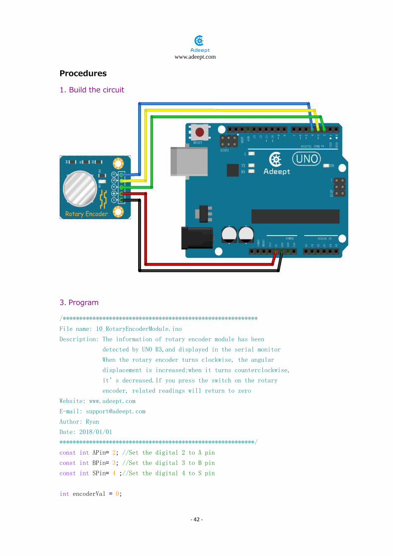
Procedures
1. Build the circuit
3. Program
/***********************************************************
File name: 10_RotaryEncoderModule.ino
Description: The information of rotary encoder module has been
detected by UNO R3,and displayed in the serial monitor
When the rotary encoder turns clockwise, the angular
displacement is increased;when it turns counterclockwise,
it’s decreased.If you press the switch on the rotary
encoder, related readings will return to zero
Website: www.adeept.com
E-mail: [email protected]
Author: Ryan
Date: 2018/01/01
***********************************************************/
const int APin= 2; //Set the digital 2 to A pin
const int BPin= 3; //Set the digital 3 to B pin
const int SPin= 4 ;//Set the digital 4 to S pin
int encoderVal = 0;

www.adeept.com
- 43 -
void setup()
{
pinMode(APin, INPUT);//initialize the A pin as input
pinMode(BPin, INPUT);//initialize the B pin as input
pinMode(SPin, INPUT);//initialize the S pin as input
Serial.begin(9600); //opens serial port, sets data rate to 9600 bps
}
void loop()
{
int change = getRotaryEncoder();
encoderVal = encoderVal - change;
if(digitalRead(SPin) == LOW)
{
encoderVal = 0;
}
Serial.println(encoderVal);
}
int getRotaryEncoder(void)
{
static int oldA = HIGH; //set the oldA as HIGH
static int oldB = HIGH; //set the oldB as HIGH
int result = 0;
int newA = digitalRead(APin); //read the value of APin to newA
int newB = digitalRead(BPin); //read the value of BPin to newB
if (newA != oldA || newB != oldB)//if the value of APin or the BPin has changed
{
if (oldA == HIGH && newA == LOW)// something has changed
{
result = (oldB * 2 - 1);
}
}
oldA = newA;
oldB = newB;
return result;
}

www.adeept.com
- 44 -
3. Compile the program and upload to Arduino UNO board
when you rotate the rotary encoder clockwise or anticlockwise, or you press down it, you can see the corresponding value on the window

www.adeept.com
- 45 -
Summary
Through the lesson, you may have mastered the working principle of the rotary encoder. In the future you can use it to make more interesting experiments.

www.adeept.com
- 46 -
Lesson 11 LCD1602 Overview
In this lesson, we will learn how to use a character display device—LCD1602 on the Arduino platform. First, we make the LCD1602 display a string "Hello Geeks!" scrolling,then display“Adeept”and“www.adeept.com”static.
Requirement
- 1* Arduino UNO - 1* USB cable - 1* LCD1602 - 1* 10KΩ Potentiometer - 1* Breadboard - Several Jumper wires
Principle
LCD1602 is a kind of character LCD display. The LCD has a parallel interface, meaning that the microcontroller has to manipulate several interface pins at once to control the display. The interface consists of the following pins:
● A register select (RS) pin that controls where in the LCD's memory you're writing data to. You can select either the data register, which holds what goes on the screen, or an instruction register, which is where the LCD's controller looks for instructions on what to do next.
● A Read/Write (R/W) pin that selects reading mode or writing mode
● An Enable pin that enables writing to the registers
● 8 data pins (D0-D7). The state of these pins (high or low) are the bits that you're writing to a register when you write, or the values when you read.
● There's also a display contrast pin (Vo), power supply pins (+5V and Gnd) and LED Backlight (Bklt+ and BKlt-) pins that you can use to power the LCD, control the display contrast, and turn on or off the LED backlight respectively.
The process of controlling the display involves putting the data that form the image of what you want to display into the data registers, then putting instructions in the instruction register. The LiquidCrystal Library simplifies this

www.adeept.com
- 47 -
for you so you don't need to know the low-level instructions.
The Hitachi-compatible LCDs can be controlled in two modes: 4-bit or 8-bit. The 4-bit mode requires seven I/O pins from the Arduino, while the 8-bit mode requires 11 pins. For displaying text on the screen, you can do most everything in 4-bit mode, so example shows how to control a 2x16 LCD in 4-bit mode.
A potentiometer , informally a pot, is a three-terminal resistor with a sliding or rotating contact that forms an adjustable voltage divider. If only two terminals are used, one end and the wiper, it acts as a variable resistor or rheostat.
Key function:
●begin() Specifies the dimensions (width and height) of the display. Syntax lcd.begin(cols, rows) Parameters lcd: a variable of type LiquidCrystal cols: the number of columns that the display has rows: the number of rows that the display has
●setCursor() Position the LCD cursor; that is, set the location at which subsequent text written to the LCD will be displayed. Syntax lcd.setCursor(col, row) Parameters lcd: a variable of type LiquidCrystal col: the column at which to position the cursor (with 0 being the first column) row: the row at which to position the cursor (with 0 being the first row)
●scrollDisplayLeft() Scrolls the contents of the display (text and cursor) one space to the left. Syntax lcd.scrollDisplayLeft() Parameters lcd: a variable of type LiquidCrystal

www.adeept.com
- 48 -
Example scrollDisplayLeft() and scrollDisplayRight() See also scrollDisplayRight()
●print() Prints text to the LCD. Syntax lcd.print(data) lcd.print(data, BASE) Parameters lcd: a variable of type LiquidCrystal data: the data to print (char, byte, int, long, or string) BASE (optional): the base in which to print numbers: BIN for binary (base 2), DEC for decimal (base 10), OCT for octal (base 8), HEX for hexadecimal (base 16). Returns byte print() will return the number of bytes written, though reading that number is optional
●clear() Clears the LCD screen and positions the cursor in the upper-left corner. Syntax lcd.clear() Parameters lcd: a variable of type LiquidCrystal

www.adeept.com
- 49 -
Procedures
1. Build the circuit
3.Program
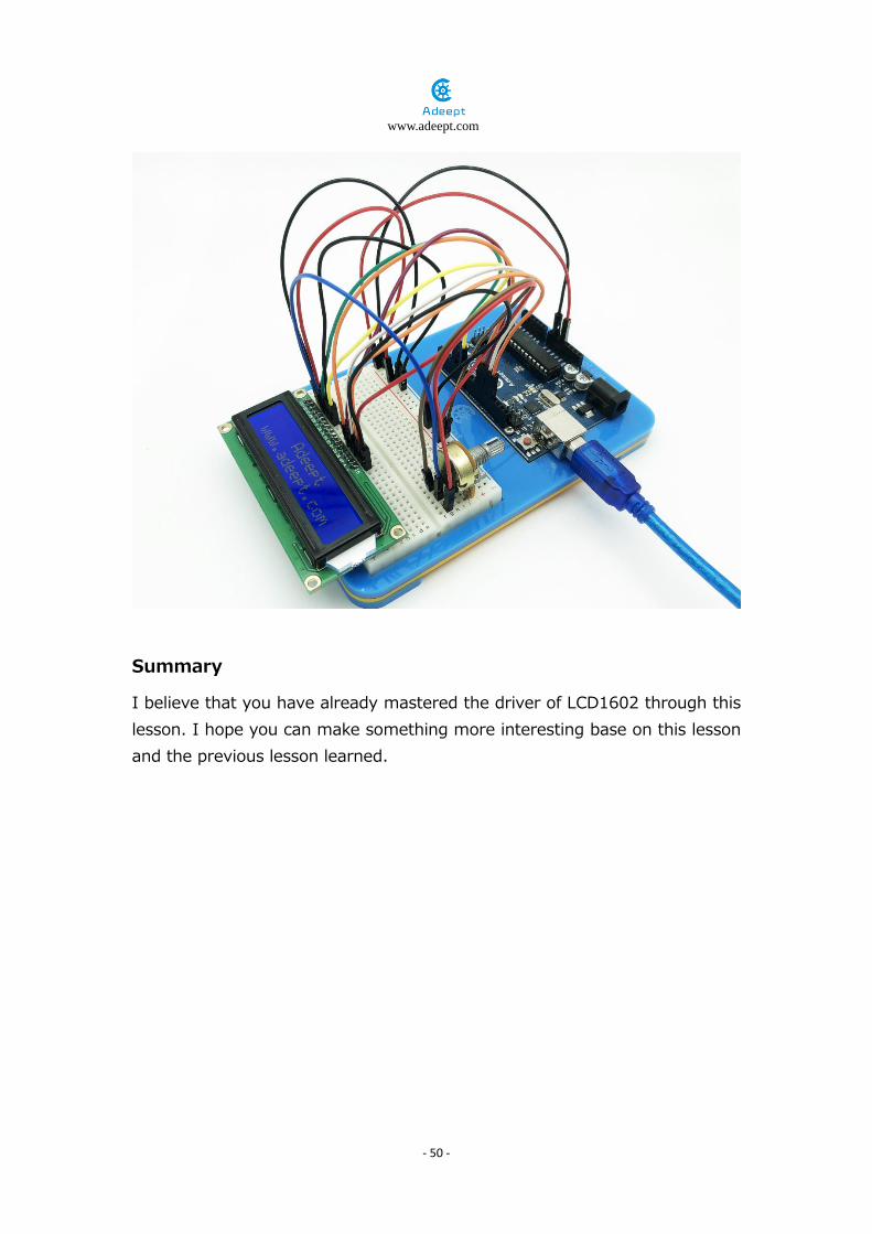
4. Compile the program and upload to Arduino UNO board Now, you can see the string "Hello Geeks!" is shown on the LCD1602 scrolling, and then the string "Adeept" and "www.adeept.com" is displayed on the LCD1602 static.
www.adeept.com
- 50 -
Summary
I believe that you have already mastered the driver of LCD1602 through this lesson. I hope you can make something more interesting base on this lesson and the previous lesson learned.
www.adeept.com
- 51 -
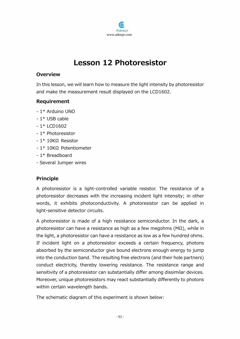
Lesson 12 Photoresistor Overview
In this lesson, we will learn how to measure the light intensity by photoresistor and make the measurement result displayed on the LCD1602.
Requirement
- 1* Arduino UNO - 1* USB cable - 1* LCD1602 - 1* Photoresistor - 1* 10KΩ Resistor - 1* 10KΩ Potentiometer - 1* Breadboard - Several Jumper wires
Principle
A photoresistor is a light-controlled variable resistor. The resistance of a photoresistor decreases with the increasing incident light intensity; in other words, it exhibits photoconductivity. A photoresistor can be applied in light-sensitive detector circuits.
A photoresistor is made of a high resistance semiconductor. In the dark, a photoresistor can have a resistance as high as a few megohms (MΩ), while in the light, a photoresistor can have a resistance as low as a few hundred ohms. If incident light on a photoresistor exceeds a certain frequency, photons absorbed by the semiconductor give bound electrons enough energy to jump into the conduction band. The resulting free electrons (and their hole partners) conduct electricity, thereby lowering resistance. The resistance range and sensitivity of a photoresistor can substantially differ among dissimilar devices. Moreover, unique photoresistors may react substantially differently to photons within certain wavelength bands.
The schematic diagram of this experiment is shown below:

www.adeept.com
- 52 -
With the increase of the light intensity, the resistance of photoresistor will be decreased. The voltage of GPIO port in the above figure will become high.
Procedures
1. Build the circuit
www.adeept.com
- 53 -
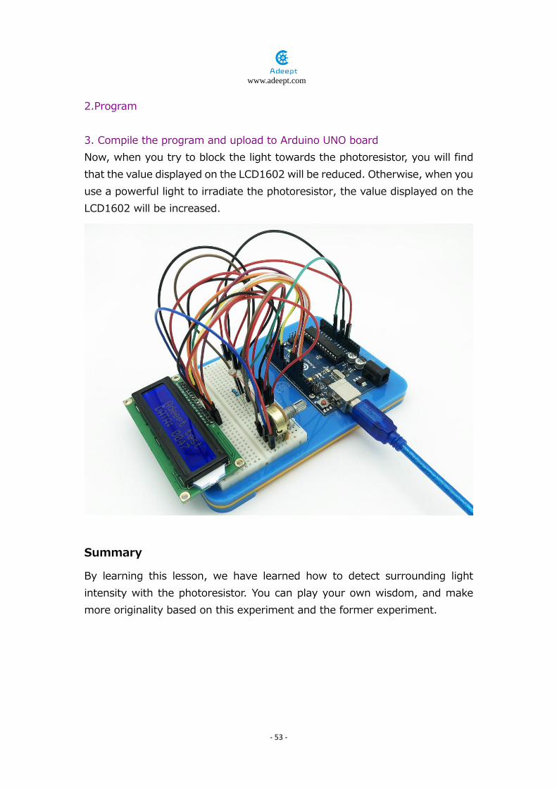
2.Program 3. Compile the program and upload to Arduino UNO board Now, when you try to block the light towards the photoresistor, you will find that the value displayed on the LCD1602 will be reduced. Otherwise, when you use a powerful light to irradiate the photoresistor, the value displayed on the LCD1602 will be increased.
Summary
By learning this lesson, we have learned how to detect surrounding light intensity with the photoresistor. You can play your own wisdom, and make more originality based on this experiment and the former experiment.

www.adeept.com
- 54 -
Lesson 13 Using a thermistor to measure the temperature
Overview
In this lesson, we will learn how to use a thermistor to collect temperature by programming Arduino. The information which a thermistor collects temperature is displayed on the LCD1602.
Requirement
- 1* Arduino UNO - 1* USB Cable - 1* LCD1602 - 1* 10KΩ Resistor - 1* Thermistor sensor - 1* Breadboard - Several Jumper Wires
Principle
A thermistor is a type of resistor whose resistance varies significantly with temperature, more so than in standard resistors. We are using MF52 NTC thermistor type. BTC thermistor is usually used as a temperature sensor.
MF52 thermistor key parameters:
B-parameter:3470.
25℃ resistor:10KΩ.

www.adeept.com
- 55 -
The relationship between the resistance of thermistor and temperature is as follows:
𝑹𝑹𝒕𝒕𝒕𝒕𝒕𝒕𝒕𝒕𝒕𝒕𝒕𝒕𝒕𝒕𝒕𝒕𝒕𝒕𝒕𝒕 = 𝑹𝑹 ∗ 𝒕𝒕�𝑩𝑩∗� 𝟏𝟏𝑻𝑻𝟏𝟏
− 𝟏𝟏𝑻𝑻𝟐𝟐��
𝑹𝑹𝒕𝒕𝒕𝒕𝒕𝒕𝒕𝒕𝒕𝒕𝒕𝒕𝒕𝒕𝒕𝒕𝒕𝒕𝒕𝒕 : the resistance of thermistor at temperature T1
𝐑𝐑 : The nominal resistance of thermistor at room temperature T2;
𝐞 : 2.718281828459;
𝐁 : It is one of the important parameters of thermistor;
𝑻𝑻𝟏𝟏 : the Kelvin temperature that you want to measure.
𝑻𝑻𝟐𝟐 : At the condition of room temperature 25 ℃ (298.15K), the standard resistance of MF52 thermistor is 10K;
Kelvin temperature = 273.15 (absolute temperature) + degrees Celsius;
After transforming the above equation, we can get to the following formula:
𝑻𝑻𝟏𝟏 =𝑩𝑩
�𝒍𝒏�𝑹𝑹𝒕𝒕𝒕𝒕𝒕𝒕𝒕𝒕𝒕𝒕𝒕𝒕𝒕𝒕𝒕𝒕𝒕𝒕𝒕𝒕
𝑹𝑹 � + 𝑩𝑩𝑻𝑻𝟐𝟐�

www.adeept.com
- 56 -
Procedures
1. Build the circuit
2. Program 3. Compile the program and upload to Arduino UNO board Now, you can see the temperature which is collected by thermistor on the LCD1602.

www.adeept.com
- 57 -
Summary
By learning this lesson, I believe you have learned to use a thermistor to measure temperature. Next, you can use a thermistor to produce some interesting applications.

www.adeept.com
- 58 -
Lesson 14 temperature alarm Overview
In this lesson, we'll try how to make a temperature alarm.
Requirement
- 1* Arduino UNO - 1* USB Cable - 1* temperature sensor - 1* buzzer - 1* Breadboard - 1* 10kΩResistor - Several Jumper Wires
Procedures
1. Build the circuit

www.adeept.com
- 59 -
2. Program
3. Compile the program and upload to Arduino UNO board Now, you may not hear the buzzer beep, since the temperature has not reached 27℃. When it does, the buzzer will beep.
Summary
In this lesson, we learnt the principle and application of the temperature sensor. Surely you can also make other fascinating experiments apart from this alarm, like an ambient temperature detector or others.

www.adeept.com
- 60 -
Lesson 15 7-segment display Overview
In this lesson, we will program the Arduino to achieve the controlling of segment display.
Requirement
- 1* Arduino UNO - 1* USB cable - 1* 220Ω Resistor - 1* 7-Segment display - 1* Breadboard - Several Jumper wires
Principle
The seven-segment display is a form of electronic display device for displaying decimal numerals that is an alternative to the more complex dot matrix displays.
Seven-segment displays are widely used in digital clocks, electronic meters, basic calculators, and other electronic devices that display numerical information.
The seven-segment display is an 8-shaped LED display device composed of eight LEDs (including a decimal point), these segments respectively named a, b, c, d, e, f, g, dp.
The segment display can be divided into common anode and common cathode segment display by internal connections.

www.adeept.com
- 61 -
When using a common anode LED, the common anode should to be connected to the power supply (VCC); when using a common cathode LED, the common cathode should be connected to the ground (GND).
Each segment of a segment display is composed of LED, so a resistor is needed for protecting the LED.
A 7-segment display has seven segments for displaying a figure and a segment for displaying a decimal point. If you want to display a number ‘1’, you should only light the segment b and c.

www.adeept.com
- 62 -
Procedures
1. Build the circuit
2. Program 3. Compile the program and upload to Arduino UNO board Now, you should see the number 0~9 are displayed on the segment display.

www.adeept.com
- 63 -
Summary
Through this lesson, we have learned the principle and programming of segment display. I hope you can combine the former course to modify the code we provided in this lesson to achieve cooler originality.
www.adeept.com
- 64 -
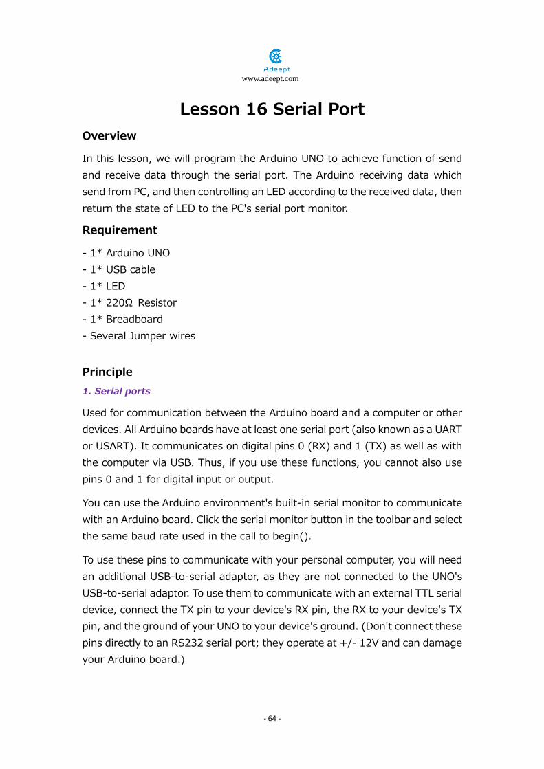
Lesson 16 Serial Port Overview
In this lesson, we will program the Arduino UNO to achieve function of send and receive data through the serial port. The Arduino receiving data which send from PC, and then controlling an LED according to the received data, then return the state of LED to the PC's serial port monitor.
Requirement
- 1* Arduino UNO - 1* USB cable - 1* LED - 1* 220Ω Resistor - 1* Breadboard - Several Jumper wires
Principle
1. Serial ports
Used for communication between the Arduino board and a computer or other devices. All Arduino boards have at least one serial port (also known as a UART or USART). It communicates on digital pins 0 (RX) and 1 (TX) as well as with the computer via USB. Thus, if you use these functions, you cannot also use pins 0 and 1 for digital input or output.
You can use the Arduino environment's built-in serial monitor to communicate with an Arduino board. Click the serial monitor button in the toolbar and select the same baud rate used in the call to begin().
To use these pins to communicate with your personal computer, you will need an additional USB-to-serial adaptor, as they are not connected to the UNO's USB-to-serial adaptor. To use them to communicate with an external TTL serial device, connect the TX pin to your device's RX pin, the RX to your device's TX pin, and the ground of your UNO to your device's ground. (Don't connect these pins directly to an RS232 serial port; they operate at +/- 12V and can damage your Arduino board.)
www.adeept.com
- 65 -
2. Key function
●begin() Sets the data rate in bits per second (baud) for serial data transmission. For communicating with the computer, use one of these rates: 300, 1200, 2400, 4800, 9600, 14400, 19200, 28800, 38400, 57600, or 115200. You can, however, specify other rates - for example, to communicate over pins 0 and 1 with a component that requires a particular baud rate.
Syntax Serial.begin(speed) Parameters speed: in bits per second (baud) - long Returns nothing
●print() Prints data to the serial port as human-readable ASCII text. This command can take many forms. Numbers are printed using an ASCII character for each digit. Floats are similarly printed as ASCII digits, defaulting to two decimal places. Bytes are sent as a single character. Characters and strings are sent as is. For example: Serial.print(78) gives “78” Serial.print(1.23456) gives “1.23” Serial.print('N') gives “N” Serial.print(“Hello world.”) gives “Hello world.” An optional second parameter specifies the base (format) to use; permitted values are BIN (binary, or base 2), OCT (octal, or base 8), DEC (decimal, or base 10), HEX (hexadecimal, or base 16). For floating point numbers, this parameter specifies the number of decimal places to use. For example: Serial.print(78, BIN) gives “1001110” Serial.print(78, OCT) gives “116” Serial.print(78, DEC) gives “78” Serial.print(78, HEX) gives “4E” Serial.println(1.23456, 0) gives “1” Serial.println(1.23456, 2) gives “1.23” Serial.println(1.23456, 4) gives “1.2346” You can pass flash-memory based strings to Serial.print() by wrapping them

www.adeept.com
- 66 -
with F(). For example : Serial.print(F(“Hello World”)) To send a single byte, use Serial.write(). Syntax Serial.print(val) Serial.print(val, format) Parameters val: the value to print - any data type format: specifies the number base (for integral data types) or number of decimal places (for floating point types) Returns byte print() will return the number of bytes written, though reading that number is optional
●println() Prints data to the serial port as human-readable ASCII text followed by a carriage return character (ASCII 13, or '∖r') and a newline character (ASCII 10, or '∖n'). This command takes the same forms as Serial.print(). Syntax Serial.println(val) Serial.println(val, format) Parameters val: the value to print - any data type format: specifies the number base (for integral data types) or number of decimal places (for floating point types) Returns byte println() will return the number of bytes written, though reading that number is optional
●read() Reads incoming serial data. read() inherits from the Stream utility class. Syntax Serial.read() Parameters None Returns the first byte of incoming serial data available (or -1 if no data is available) - int

www.adeept.com
- 67 -
Procedures
1. Build the circuit
4. Program 3. Compile the program and upload to Arduino UNO board Open the port monitor, and then select the appropriate baud rate according to the program.
Now, if you send a character‘1’or‘0’on the serial monitor, the state of LED will be lit or gone out.

www.adeept.com
- 68 -

www.adeept.com
- 69 -
Summary
Through this lesson, you should have understood that the computer can send data to Arduino UNO via the serial port, and then control the state of LED. I hope you can use your head to make more interesting things based on this lesson.
www.adeept.com
- 70 -
Lesson 17 DC motor fan Overview
In this comprehensive experiment, we will learn how to control the state of DC motor with Arduino, and the state will be displayed through the LED at the same time. The state of DC motor includes its forward, reverse, acceleration, deceleration and stop.
Requirement
- 1* Arduino UNO - 1* USB Cable - 1* DC motor module - 1* Breadboard - 1* The fan blade - Several Jumper wires
Principle 1. DC motor
A DC motor is any of a class of electrical machines that converts direct current electrical power into mechanical power. The most common types rely on the forces produced by magnetic fields. Nearly all types of DC motors have some internal mechanism, either electromechanical or electronic, to periodically change the direction of current flow in part of the motor. Most types produce rotary motion; a linear motor directly produces force and motion in a straight line.

www.adeept.com
- 71 -
DC motors were the first type widely used, since they could be powered from existing direct-current lighting power distribution systems. A DC motor's speed can be controlled over a wide range, using either a variable supply voltage or by changing the strength of current in its field windings. Small DC motors are used in tools, toys, and appliances. The universal motor can operate on direct current but is a lightweight motor used for portable power tools and appliances.

www.adeept.com
- 72 -
2. Key functions
●switch / case statements
Like if statements, switch…case controls the flow of programs by allowing programmers to specify different code that should be executed in various conditions. In particular, a switch statement compares the value of a variable to the values specified in case statements. When a case statement is found whose value matches that of the variable, the code in that case statement is run.
The break keyword exits the switch statement, and is typically used at the end of each case. Without a break statement, the switch statement will continue executing the following expressions (“falling-through”) until a break, or the end of the switch statement is reached.
Example
switch (var) {
case 1:
//do something when var equals 1
break;
case 2:
//do something when var equals 2
break;
default:
// if nothing else matches, do the default
// default is optional
}
Syntax
switch (var) {
case label:
// statements
break;
case label:
// statements
break;
default:
// statements
}

www.adeept.com
- 73 -
Parameters
var: the variable whose value to compare to the various cases label: a value to compare the variable to
Procedures
1. Build the circuit (Make sure that the circuit connection is correct and then power, otherwise it may cause the chips to burn.)
3. Program

www.adeept.com
- 74 -
3. Compile the program and upload to Arduino UNO board Now we can see the motor turning
Summary
I think you must have grasped the basic theory and programming of the DC motor after studying this experiment. You not only can forward and reverse it, but also can regulate its speed. Besides, you can do some interesting applications with the combination of this course and your prior knowledge.

www.adeept.com
- 75 -
Lesson 18 Controlling Servo motor
Overview
In this lesson, we will introduce a new electronic device (Servo) to you, and tell you how to control it with the Arduino UNO.
Requirement
- 1* Arduino UNO - 1* USB Cable - 1* Servo - Several Jumper Wires
Principle 1. Servo motor
The servo motor have three wires: power, ground, and signal. The power wire is typically red, and should be connected to the 5V pin on the Arduino board. The ground wire is typically black or brown and should be connected to a ground pin on the Arduino board. The signal pin is typically yellow, orange or white and should be connected to a digital pin on the Arduino board. Note the servo motor draw considerable power, so if you need to drive more than one or two, you'll probably need to power them from a separate supply (i.e. not the +5V pin on your Arduino). Be sure to connect the grounds of the Arduino and external power supply together.
2. Servo library
This library allows an Arduino board to control RC (hobby) servo motors. Servos have integrated gears and a shaft that can be precisely controlled. Standard servos allow the shaft to be positioned at various angles, usually between 0 and 180 degrees. Continuous rotation servos allow the rotation of the shaft to be set to various speeds.
3. Key functions:
●attach()
Attach the Servo variable to a pin. Note that in Arduino 0016 and earlier, the Servo library supports only servos on only two pins: 9 and 10.
Syntax

www.adeept.com
- 76 -
servo.attach(pin) servo.attach(pin, min, max)
Parameters
servo: a variable of type Servo
pin: the number of the pin that the servo is attached to
min (optional): the pulse width, in microseconds, corresponding to the minimum (0-degree) angle on the servo (defaults to 544)
max (optional): the pulse width, in microseconds, corresponding to the maximum (180-degree) angle on the servo (defaults to 2400)
Procedures
1. Build the circuit

www.adeept.com
- 77 -
2. Program 3. Compile the program and upload to Arduino UNO board Now, you should see the servo rotate 180 degrees, and then rotate in opposite direction.
Summary
By learning this lesson, you should have known that the Arduino provided a servo library to control a servo. By using the servo library, you can easily control a servo. Just enjoy your imagination and make some interesting applications.

www.adeept.com
- 78 -
Lesson 19 ultrasonic distance sensor Overview
In this lesson, we will learn how to measure the distance by the ultrasonic distance sensor.
Requirement
- 1* Arduino UNO - 1* USB Cable - 1* Ultrasonic Distance Sensor - 1* LCD1602 - 1* 10KΩ Potentiometer - Several Jumper Wires
Principle
This recipe uses the popular Parallax PING ultrasonic distance sensor to measure the distance of an object ranging from 2 cm to around 3 m.
Ultrasonic sensors provide a measurement of the time it takes for sound to bounce off an object and return to the sensor. The “ping” sound pulse is generated when the pingPin level goes HIGH for two micro-seconds. The

www.adeept.com
- 79 -
sensor will then generate a pulse that terminates when the sound returns. The width of the pulse is proportional to the distance the sound traveled and the sketch then uses the pulseIn function to measure that duration. The speed of sound is 340 meters per second, which is 29 microseconds per centimeter. The formula for the distance of the round trip is: RoundTrip = microseconds / 29.
So, the formula for the one-way distance in centimeters is: microseconds / 29 / 2
Procedures
1. Build the circuit

www.adeept.com
- 80 -
2.Program 3. Compile the program and upload to Arduino UNO board Now, when you try to change the distance between the ultrasonic module and the obstacles, you will find the distance value displayed on the LCD1602 will be changed.

www.adeept.com
- 81 -
Summary
By learning this lesson, we have learned how to use an LCD screen to read the distance detected by the ultrasound.I hope you can make other interesting experiments with ultrasonic modules in your spare time.

www.adeept.com
- 82 -
Lesson 20 Control a servo with ultrasonic distance sensor
Overview
In this lesson, we will measure the distance with the ultrasonic module, and then convert the distance into the rotation angle of the servo.
Requirement
- 1* Arduino UNO - 1* USB Cable - 1* Ultrasonic Distance Sensor - 1* Servo - 1* Breadboard - Several Jumper Wires
Principle
In this experiment, we collect the distance data between ultrasonic module and the obstacle with the ultrasonic distance sensor. Then, converting the distance data into the rotation angle of the servo by programing the Arduino UNO.
Procedures
1. Build the circuit

www.adeept.com
- 83 -
2.Program 3. Compile the program and upload to Arduino UNO board Now we just use our hands to move in front of the ultrasound, and the steering gear can rotate the Angle.
Summary
By learning this lesson, we have mastered how to reading data from the ultrasound for steering gear to the corresponding point of view, I hope you can imagination using the learning of all components before make an inter combination experiment.

www.adeept.com
- 84 -
Lesson 21 Combined LED Experiment Overview
In this lesson, let's study how to control LED on/off and buzzer to beep in different frequencies.
Requirement
- 1* Arduino UNO - 1* USB cable - 3* button - 3* LED - 1* 1kΩresistor - 1* passive buzzer - 1* NPN Transistor (S8050) - 1* breadboard - 1* Serveral Jumper Wires
Procedures
1. Build the circuit

www.adeept.com
- 85 -
2. Program 3. Compile the program and upload to Arduino UNO board now when you press down button 1, you can hear the buzzer beeping, then the LED lights up, and when you press down the button 1 again, the buzzer beeps, and the LED goes out, when you press down the other two buttons, you can hear the buzzer beeps with different tones
Summary
In this lesson, you should have known how to control the LED and make the buzzer beep in different frequencies by multiple buttons. Based on the knowledge, you can DIY a small piano then!

www.adeept.com
- 86 -
Lesson 22 Ultrasonic Fan
Overview
In this lesson, let's try to make an ultrasonic fan.
Requirement
- 1* Arduino UNO - 1* USB Cable - 1* DCmotor - 1* Ultrasonic Distance Sensor - 1* Breadboard - 1* 9v Battery - Several Jumper Wires
Procedures
1. Build the circuit

www.adeept.com
- 87 -
2. Program 3. Compile the program and upload to Arduino UNO board When the ultrasonic detects an obstacle nearby ahead, the fan will slow down spinning. When it can tell the obstacle gets farther, it'll speed up spinning.
Summary
In this lesson, you have learnt how to make an ultrasonic fan. With a good command of the principle, you can make other amazing projects.

www.adeept.com
- 88 -
Lesson 23 Reversing Radar Overview
In this lesson, we start to study how to DIY a reversing radar.
Requirement
- 1* Arduino UNO - 1* USB Cable - 1* RGB - 1* passive buzzer - 1* 1kΩResistor - 1* NPN Transistor (S8050) - 4* 220Ω Resistor - 1* Breadboard - Several Jumper Wires
Procedures
1. Build the circuit

www.adeept.com
- 89 -
2.Program 3. Compile the program and upload to Arduino UNO board Now, you can see the color of the RGB LED change accordingly as the ultrasonic detects different distance results, and the buzzer beeps in different frequencies.
Summary
By this lesson, you should have learnt the principle of the ultrasonic. Now you can free your imagination and make more fascinating creative projects together with the knowledge of the elements learnt about previously.