Embed Size (px)
Citation preview

_,,EPARED FOR
NATIONAL AEF_ONAUTICS AND SPACE ADMINISTRATION
' " MASA LEWIS RESEARCH CENTER _ __r<", _ ".:. _' CONTRACT NAS3_20033
_.-'i,..,_I .:%_%}Y
i S"
00000001
https://ntrs.nasa.gov/search.jsp?R=19770016164 2019-08-06T11:59:55+00:00Z

, !b,
/NasaAeronautics andSpace Administration
VARIABLE PITCH FAN SYSTEM
FOR J
NASA/NAVY RESEARCH AND TECHNOLOGY AIRCRAFT
BY
W. P. RYAN, D.M. BLACK, A.F. YATES
HAMILTON STANDARDDIVISION OF UNITED TECHNOLOGIES CORPORATION
PREPARED FOR
NATIONAL AERONAUTICS AND SPACE ADMINISTRATION
NASA LEWIS RESEARCH CENTERCONTRACT NAS3--20033
00000001-TSA03

Ij9m
T! R_pmt No | 2 Govelnmvn! Acc_smn No 3 tf_cq)mnt'sC_'=_1o9 No
NASA CIt 1351H5 ]VAR[ABLI,: PITCI[ FAN SYSTEM FOR NASA/NAVY RI':SI,:ARCIIAND ..... April !97_7 .........
TECIINOLOIIY AIRCRAI"T 6 Perlorm,nqt_r@n,_@honC_de
7 AuthOrIsp 8 Perforrnm00riJam,,ataonReport NO
W, P. Rynn, I), M, Black, A, F. Yates10 Work UHII No i
9 Pe_fo_mm¢30rOan_zattonNameand _ddress
Ilemilton Standard
Division of United 'Technologies 11 Contract or Grant No IWindsor l,ocks, Conn. 06096 NAS,q-20033
13. Type st Reportand Per,odCovered12. SponsoringAgencyNameand Address
Nmionnl Aeronautics and Space Administration Contractor Report
Washington, l). C. 20546 14.SponsoringAgencyCode
15. SupplementaryNotes
Project Manager, Albert G. Powers, Propulsion Systems Project Office, NASA Lewis Research Center,
Cleveland, Ohio 44135
16 Abstract
Preliminary design of a shaft driven, variable-pitch lift fan and lift-cruise fan was conducted for a V/STOL
Research and Technology Aircraft. "The lift fan and lift-cruise fan employed a common rotor of 157.5 cm
(62 inch) diameter, 1.18 pressure ratio variable-pitch fan designed to operate at a rotor tip speed of 284 raps(932 fps).
Preliminary definitions were coordinated for lift fan/aircraft and lift-cruise fan/engine interfaces.
Fan performance maps were prepared and detailed aerodynamic characteristics were established. Cost/
weight/risk trade studies were conducted for the blade and fan case. Structural sizing was conducted for
major components and weights determined for both the lift and IHt-eruise fans.
I ? Key Words (Suggestedby Author(all 18 D0strlbut,onSlatement
I,ift FanLift-Cruise FanVariable Pitch
V/S'I'OL (Vertical/Short 'Takeoff and Landing) l'nclassifled - UnlimitedRTA (Research and Technology Aircraft)
,9S tyClass,,lottinsreport).... I20S ,yOa.,,o,,..o,...... ..... I ?t .o of.._e, I 2;P.,-'"Unclas.ifie,i Unclassified ..........L_ 90 .... I --_:
• Fnr ssh' hv lhP N,th011,9!Tl'Lh_m_' I:lf _I,:_d,_r '_t_r_,,, : _[_UU,'%,r'_ ?,,C_m! ?/lFi]
iii/iv
00000001-TSA04
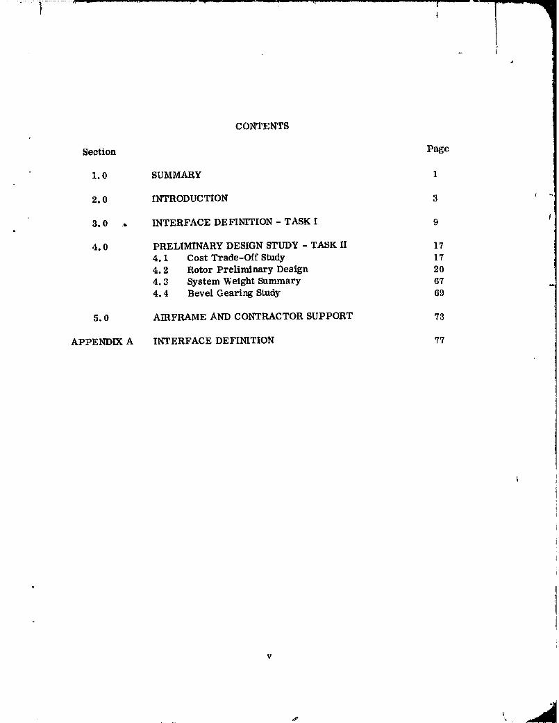
CONTENTS
Section Page
1.0 SUMMARY 1
2.0 INTRODUCTION 3 '
3.0 • INTERFACE DEFINITION - TASK I 9 I
4.0 PRELIMINARY DESIGN STUDY - TASK II 17
4.1 Cost Trade-Off Study 17
4.2 Rotor Preliminary Design 20
4.3 System Weight Summary 674.4 Bevel Gearing Study 69
5.0 AIRFRAME AND CONTRACTOR SUPPORT 73
APPENDIX A INTERFACE DEFINITION 77
° I
V
00000001-TSA05

[ . I , I t'" ',,'
ILLUSTRATIONS
Figure Page
2-1 Variable Pitch Fan Background 42-2 Conceptual RTA Design 62-3 Fan Rotor Assembly 7 '
3-1 Lift-Cruise Fan Rotor 11 I3-2 Lift Fan- Boeing 133-3 Lift Fan - McAir 15
4-1 Solid Titanium Blade Critical Speeds 194-2 Lift-C raise Fan Fiowpath 224-3 Lift-Craise Fan Performance 234-4 Lift-Craise Fan Performance 244-5 Lift-Craise Fan Performance 254-6 Lift-Cruise Fan Performance 264-7 Lift-Cruise Fan Performance 274-8 Lift-CrUise Fan Performance 284-9 Lift-Craise Fan Supercharge Performance 294-10 Lift-Cruise Fan Supercharge Performance 304-11 Lift-Cruise Fan Supercharge Performance 314-12 Lift-Cruise Fan Supercharge Performance 324-13 Lift-Cruise Fan Supercharge Performance 334-14 Lift-Cruise Fan Supercharge Performance 344-15 Distortion Geometry 384-16 Representative Distortion Patterns 394-17 Inlet Distortion Indices 404-18 RTA Fan Distortiou Sensitivity 424-19 V/STOL Fan Blade Geometry 43 '4-20 Fan Blade Spanwise Geometry 444-21 Blade Critical Speeds 464-22 Rotor Axial Velocity Profiles 484-23 Material Design Strength 494-24 FOD Impact Geometry 524-25 Blade FOD Impact Loads 534-26 Blade FOD Impact Deflections 544-27 Peak Blade FOD Stresses 564-28 Mid-Blade Spanwise Bending Stress 57
|
4-29 FOD Impact Station Spanwise Bending Stress 5_
vi
00000001-TSA06

ILLUSTRATIONS (Cont) j
Figure Page
4-30 Retention Contact Stress 604-31 Blade Retention Stress Experience 61 ,4-32 Disc Stress Summary 624-33 Actuator Concept 64 J4-34 Variable Pitch Control System 654-35 System Wef.ght Experience 684-36 Lift Fan Bevel Gear Assembly 70
5-1 Lift Fan Power 75
i
vii
00000001-TSA07
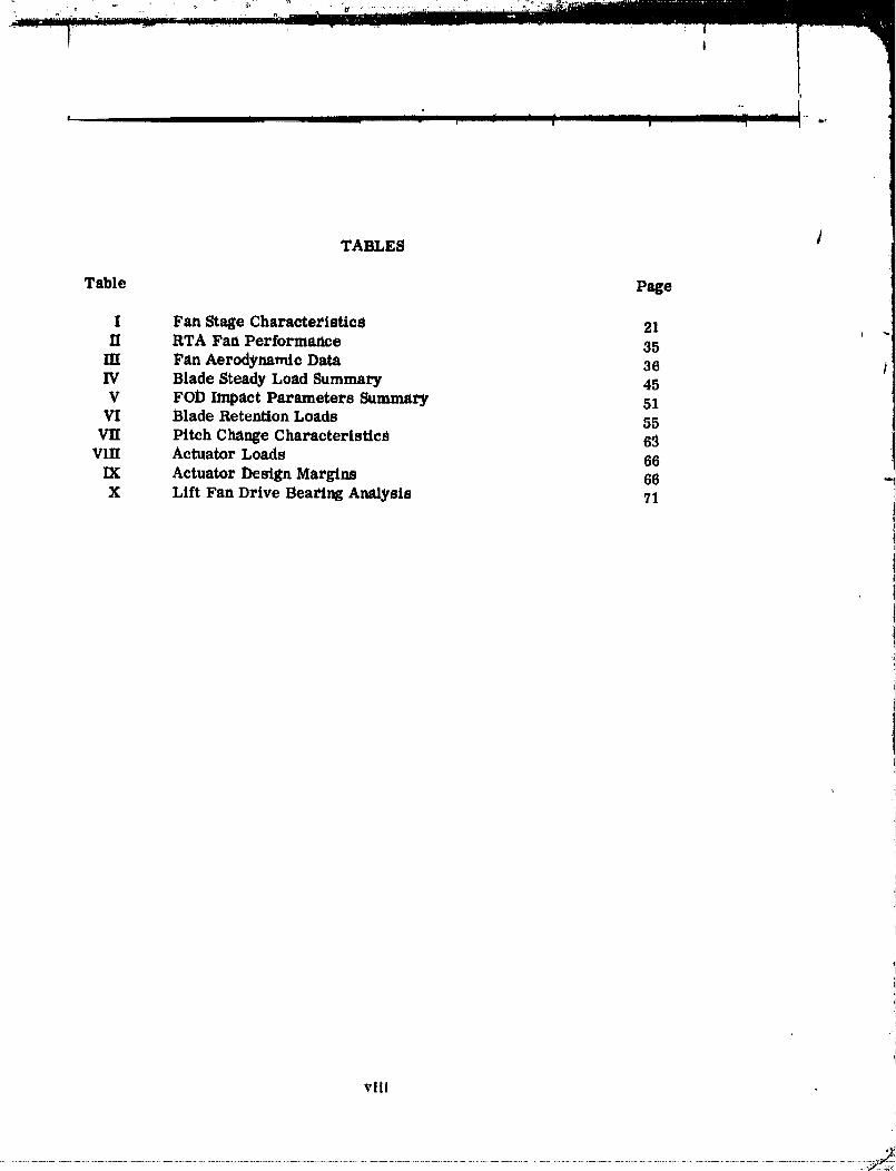
TABLES /
Table Page
I Fan Stage Characteristics 21 ,IT RTA Fan Performance 35
[lI Fan Aerodynamic Data 36 !IV Blade Steady Load Summary 45V FOD Impact Parameters Summary 51
VI Blade Retention Loads 55VII Pitch Change Characteristics 69
VIII Actuator Loads 66IX Actuator Design Margins 66X Lift Fan Drive Beating Analysis 71
viii
00000001-TSA08

!
SYMBOLS AND ABBREVIATIONS
B chordB/A1 Boron/Aiumlnum
BMAD (BAC) Boeing Mllltary Airplane DivisionCps cycles per secondCA Circular Arccm centimeterDf diffusion factorDCA Double Circular ArcDDA Detroit Diesel Allison i
deg degreefps feet per secondFPR fan pressure ratioFOD Foreign Object Damageft feet
gpm gallon per minuteHz hertzin inch
kg kilogramK 0 circumferential distortion indexKR radial distortion !ndexkw kilowattKSI thousand pounds per square inchKN thousand newtonsKt KnotsLeRC Lewis Research Centerlb poundraps meter per secondMm Meridianal roach numberMr relative roach numberMa absolute math numbermm millimeterMcAir McDonnell Aircraft CompanyM Meter
N/_ Corrected speed
NASA National Aeronautics & Space Administr_,tionN newtons
P/P Stagnation pressure ratio
pp. PressUre ratio 1P Stagnation Pressure '1psi pound per square inchRPM Revolutions per minutetad radlans
ix
00000001-TSA09

SYMBOLS AND ABBREVIATIONS (Cont)
Re, ROckwell hardness /RTA Research and Technology Aircraft
R/RT blade station/blade tip radiuss secondSOTA State-of-the-Art
sec second ' _tSHP Shaft horsepower
t/b blqde thr,ekness ratio i iTi Titanium JT/T Stag'nation temperature ratio iJ1
freeStream velocity ]VoV/STOL Vertlcal/Short Take-Off and Landing ;I
VP Variable Pitch _z loss coefficient
absolute air anglefl relative air angle0 Tamb/519°R0 * camber angle
efficiencyad adiabatic efficiency
Beta (fan blade angle)
WO_r'_6A Corrected specific airflow
_" gap _:
i
X
O0000001-TSAIO

tJ1!
SECTION 1.0SUMM,A,Ry
This report presents the results of design studies of shaft driven, variable.pitch liftand lift-cruise fans for use in the NASA/NAVY "V/STOL Research and TechnologyAircraft Program". The work was conducted between May and December 1976 under ,NASA LeRC contract NAS3-20033.
J
The objective of these studies was to provide technical arLdprogram information foruse by NASA and designated engine and airframe contractors working on V/STOLpropulsion system and aircraft studies; i.e. ; Detroit Diesel Allison (DDA), BoeingMilitary Aircraft Division (BMAD) and McDoa_ell Aircraft (McAir).
This work described herein builds upon the results of design studies conducted during1975 by Hamilton Standard under NASA contract NAS3-19414. The earlier studieswere aimed at providing parametric and point design data on lift and lift-cruise fansto support Boeingta studies of a Navy V/STOL operational aircraft.
The fan design covered herein for the current program is a 157.5 em (62 in) diameter,1.18 pressure ratio variable pitch fan designed to operate at a tip speed of 284 raps(932 fps).
Under the current program Hamilton Standard coordinated preliminary interface defi-ntUons with Detroit Diesel Allison relative to the lift-cruise fan for the XT701 engine;and with Boeing Military Aircraft Division and McDonnell Aircraft relative to the liftfRn for their respective V/STOL aircraft configurations. An Interface Document waspublished which covered both the lift and lift-cruise fans.
Fan performance maps were prepared and detailed aerodynamic characteristics wereestablished. Cost/Weight/Risk trade studies were conducted for the blade and fancase. Structural sizing was conducted for major components and weights determinedfor both the lift and lift-cruise fans.
00000001-TSA11

!
q ..... j _ _ n uu .,
SECTION 2.0INTRODUCTION
Aircraft capable of vertical and short take off and landing have been the st:bject of
study over an extended period of time, due to their attractiveness for a variety ofcommercial arid military applications. One such ap'flieatLon is a mult_-mission Navyairplane envisioned to meet an operational requirement in the 1990ts. The Navy oper-ational vehicle and its related propulsion system were the subject of studies by see- I
. eral contractors, including Hamilton Standard, during 1975.
During 1976, airframe and propulsion system contractors were funded by NASA tostudy a V/STOL research and technology aircraft (RTA) which could be used to inves-tigate and demonstrate the technology associated with the operational V/STOL air-craft. Two airframe contractors, BMAD and MeAl:-, studied aircraft employing shaftdriven, variable pitch fans. Both Hamilton Standard, under NASA LeRC contractNAS3-20033, and DDA supported these contractors with propulsion system technicaldata, i.e., weight, performance, interfaces, etc., and program planning informa-tion.
The RTA was to employ state-of-the-art (S_TA) technology and existing engines. Thecontrac¢ors using shaft driven variable pitch fans focused on three fan - three cngincaircraft.
Both I3MAD's and McAirts concepts employed two lift cruise fans adjacent to the aft
fuselage and a single lift fan in the vehicleOs nose which was stopped during forwardflight. A significant difference between the propulsion system approaches was thatBoeing's concept involved rotation of the direct-connected lift-cruise fan and core engineto deflect the thrust vector; while McAtr deflected the nozzle of the lift-cruise fan whileleaving the nacelle stationary.
The variable pitch fan concept which provides the basis for these and prior studieshas an extensive background as the result of efforts by llamllton Standard and NASA.
_ _ardware forThis concept ,ms been explored through model, component and full -'both ground and flight te._ting over the past ten years. Several of the models and fullscale variable pitch fans associated with the development of this technology, areshown in figure 2-1.
The work described herein was aimed at investigating the v'triable pitch fan conceptuallydesigned in 1975 for the operational aircraft, and making _uch modification as necessaryto accommodate the requirements of the RTA.
00000001-TSA12

I I ' --1 I _ I" --J I I F --1 .... 7 I _
00000001-TSA13

......... I 1 I 1 J- I_,
2.0 (Continued)
For the RTA, three turbosh_ft engines will collectively drive three Variable Pitch(VP) fans th:ough lntereonnectlvg shafting. Two fans, designed lift-cruise, are locatedon each side of the aft fuselage, directly coupled to the side mounted engines (figure 2-2).The third fan, designated lift fan, is remotely _laounted in the aircraft nose and i_ driven /by a third engine (not shown). As mentioned earlier the lift fan only operates during theV/3TOL mode. Hamilton _andard has responsibility for the lift-cruise fan rotor assem-bly ,nd rotur control regulators and the complete lift fan system.
The VP Lift Fan System is made up of four (4) major components:
- R_Jtor Assembly I
- Beta Regulator
- Gear Reduction Assembly
- Fan Case
The Rotor Assembly consists of the blades, disc, variable pitch actuator, and spinner(figure 2-3). The Beta Regulator is an electrohydraulic control unit which changesthe fan blade pitch according to a given input command. The Gear Reduction Assam.bly is incorporated in the lift fan and contains a bevel gear/cross shaft system '.odrive the fan from the aft _nounted engines. The Fan Case is the structural mou'._ingmember of the fan assembly. The fan stators are attached to the outer shell andpos:'tion the rotor housing.
This report contains preliminary technical d_ta on the Variable Pitch Fans for theNASA/NAVY Research and Technology V/STOL Aircraft.
00000001-TSA14

6
00000001-TSB01

i
....... i
I
f
l ..... -r-r"-_ ..............................
|
i
1/: N
" " - I r :"" i;''
[
Q<.Jm
7/_
00000001-TSB02

SECTION 3.0 /
INTERFACE DEFINITION - TASK I
The initial task conducted under the V/STOL fan study program was to identify and de-fine the interfaces associated with the lift and lift-cruise fansj in areas such as per-formance, mounting, cooling, control requirements and mechanical, electrical and
hydraulic interconnections. The lift-cruise fan-engine interface was coordinated with bDDA; and lift fan-aircraft interfaces were coordinated with both BMAD and McAir.
Both Hamilton Standard and DDA (contract NAS3-20034) had contractual requirementsto proVide NASA with an Interface Document identifying interfaces and defining thoseinterfaces which were established during the preliminary design study. An interfacedocument was jointly prepared which covered both the lift-cruise and lift fans. TheInterface Document which is contained in Appendix A, was preliminary in that all in-terfaces would not be defined during the design study. In this document the interfaceswhich Were not finalized during the design study are indicated as "TBD".
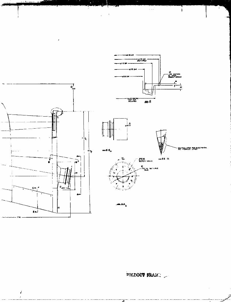
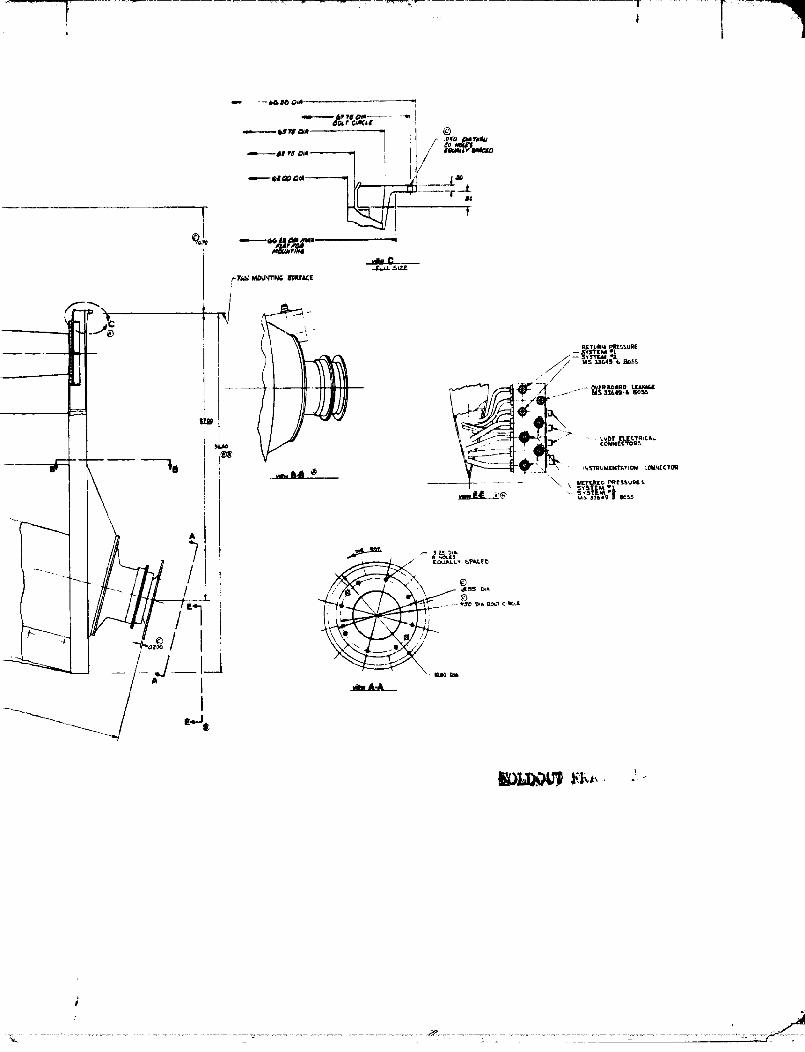
During the study, agreement was reached on a number of specific interfaces which aredefined on the three drawings noted below. Separate drawings were required for therespective Boeing and McAir lift fan installations because the drive shaft angle wasdifferent for their applications. A value of 105 ° was selected by McAir and 100 ° wasselected by _oelng.
Figure Item Drawing No.
3-1 Lift Cruise Fan Rotor SK 92250
3-2 Lift Fan - Boeing SK 92252¢
3-3 Lift Fan - McAir SK 92251
9/10
00000001-TSB03

/ !
/
.q
45 °
u,"'s / _ .._, ,.\
_O7-7/++
I SECTION D-I) ;! _ FdLL _IZE •
/1 .,y--+l" \ I / '/ "_` "+ 'Nlflllillltlltl ='_ tl/1N_Pt"t BEARING "T,ORQU[ I / :.I t i+; X [ c.++,,.,<c:+.... i_e+. _ l i
/s. r ....... ---" ' "-- "-]__.__..__
I'\ _i \ "_ ...... _iV.... _,,_ / -- ".... i-t ............. ---]........Igt _, : J,d,U DI <
I\\ \ .'\ .. \,,__t/, _:+o;.o+,.°+°+=].• -- I Sull Ar._- --_____
...... "'A "
' CZ;_-:;:::
virw AT A I L?O.,i ;&_O+ - ................ " ZX SIZ[
.11 _#4 AT i
I. I tAf.il
Figure 3-1, Lift Cruise Fan Rotor (II_I Dr_vg _K92250)
[IOI,,ID,)L,'Tl_t_/li} I ll/l_
#
O0000001-TSB04

i .¢37_" O_A -
4 05 o._
r'dcL 51ZE
SEcTioNB-B
kU_E OIL =t_
_.°,o, .. \7
...... ,,.,,..:_._.......,.
E. v_Ew AT r-E
TIN(..
I l_l ...............i .... "
' '_......;i"'°" I_'-l VIEW AT r-F
blT&ll.O_ AI_utA _ _'_IIFIONING
,'liW AT C
_OIR PR._',I_::-

Figure ._-2. Lift Fan - Boein_ (HS Dr_vg ,_922.52_
1._/14
00000001-TSB06
y
00000001-TSB07

11
+ Fibre 3-3. Lift Fan " McAtr {HS or_'_ _92251)
15/1_
/
00000001-TSB09

SECTION 4.0 I• PRELIMINARY DESIGN STUDY - TASK Ii
A preliminary design study was conducted to refine the 1.575 m (62 in. ) diameter" operational fan design concept (reference NASA CR-134988) to mec he requirements
of the NASA/NAVY Research and Technology AirCraft (RTA).
This work consisted of three major subtasks. The i_tial item was a cost trade-off i
. study to define where weight, life, risk or durability might be traded-off to reducethe program cost. The second item was to perform structural and aerodynamic anal-yses which Would generate data needed by DDA, BMAD and McAir in their respectivestudies. The third item was to optimize the design configuration for the bevel gear/cross-shaft assembly with the objective of establishing commonality between the liftand lift-cruise fants cross-shaft gearing.
4.1 COST TRADE-OFF STUDY
The lift and lift-cruise fans incorporate design features and materials aimed at pro-viding the light weight, high structural integrity, reliability, safety and life requiredfor a V/STOL application. While structural integrity, reliability and safety could notbe compromised for a flight vehicle, development risk, weight and life were felt tooffer viable trade-offs for a research and technology program.
The fan concepts were reviewed to identify areas where weight and/or life could besacrificed to reduce cost. No areas were identified where cost/lif_ or cost/risktrades would provide a significant program cost saving; however, _wo areas, the fanblades and fan case, were identified which offered promise of a significant cost savingat an increased weight.
The baseline fan blade construction incorporates a boron-aluminum (B/AI) shell and asolid titanium spar. This technology had been selected after a successful dcmovstra-tion of its ability to meet the structural and enviromncntal considerations of turbofanengines under several NASA and USAF-funded programs. The alternate constructionsconsidered were: (1) composite blade with a fiberglass-epoxy shell, and a titaniumspar; and (2) a solid titanium blade.
In the size of the V/STOL fan, the fiberglass shell did not have adequate bird striketolerance. Its shell fabrication process is quite similar to that of the B/AL shell, andthe titanium spar was common to both blades. The major cost difference between thetwo blade constructions was the higher tooling, process development and shell mate-rial cost of the B/A! composite blade. The cost savings were not large, however.
17
O0000001-TSBIO

i _" I_=_---_'-_'_
--- I _I li li ...............
4. 1 (Continued)
This blade construction had been developed for propeller blades of much larger sizethan the V/STOL fan blade where FOD is not a significant design consideration. Ex-perimental work had demonstrated that for the much smaller fan blades the fiberglass /shell had insufficient strength to transmit the loads associated with a bird strike to •the spar. Thereforet for the V/STOL fan tiffs blade would have an inadequate FODtolerance. In light of iow FOD tolerance and only modest program cost saving, thisconcept was discarded from consideration.
I
The solid tit- ,_..:lade was initially evaluated as a direct replacement for the 26composite blades. The titanium blade, however, did not have adequate stiffness re-suiting in critical speeds Within the operating range as shown in figure 4-1. Reduc-tion of the number of blades to lt_ provided sufficient increased stiffness to removethe critical speeds from the operating range and this blade was used in the trade-offstudy. The loads associated with the 18 titanium fan blades were substantially in-creased over the B/AI blades. Centrifugal load was increased by 130% and the actua-tor loads increased by 480%, This increase resulted in major rotor mass increaseof nearly 70% or 113 Kg (250 pounds). This value would be further compounded in thefan structural support weight.
The costs associated with each blade concept, including the unit blade cost, tooling andprocess development, were estimated. If was found that the solid titanium blade costswere significantly lower than those of the composite blade. As it was suspected thatthe large rotor weight increase associated with the titanium blade would affect the totalfan cost, disc and actuator costs were estimated for a fan employing both solid titaniumand B/A1 bladeS. It was determined that the heavier disc and actuator associated withthe solid titanium blade was considerably more expensive than similar hardware associ-ated with the B/A1 blades and essentially offset the savings cf the blade.
The baseline fan case is a welded titanium structure employing the manufacturingtechnology which is used in current production turbofan engines. The design consid-ered in the trade study was a fabricated aluminum structure which was riveted rather
than welded. This concept resulted in a mass increase of 27 Kg (60 pounds). Unlike tthe blade, the fan case weight does not impact on other fan structure, therefore, thecomponent weight increase is the total impact on the fan. Cost savings would resultfrom the reduced tooling and manufacturing associated with the fabricated ._luminum fanc_se.
Discussions were held with the airframe study contractors, Boeing and McDonnell,which indicated that the fan weights were critical and a,ly increase in the fan weightwould necessitate a weight reduction effort to remove a like amount from the airframe.Since identifiable lightweight concepts and materials had already been incorporated inthe design, this would be a difficult and costly task. It was concluded that the light=weight concepts and materials, i.e., the B/A1 fan blade and titanium fan case, selectedduring 1975's operntlonal aircraft fan studies, contract no. NAS.q-19414, were cost effec-tive for a research and technology aircraft.

l,'il_t.r(, .l-I. Soli(I "['il:tnitml Itl:t(lt. ('riti(.:ll SI)(,_,dF
19
.... O0000001-TSB12

4. 2 ROTOR PRELIMINARY DESIGN
The VP rotor preliminary design includes aerodynamic design and structural analyses.The variable pitch fan design selected during X97fi by BMAD for their V/BTOL Opera-tional Aircraft provided the basis for the rotor preliminary design. This fan as des-cribed in NASA report CIt134988 had a pressure ratio of 1. $ and a diameter of 1. G75meters (62 in, ).
4.2.1 Aerodynamic AnalysesJ
The aerodynamic analysis was conducted to provide detail fan performance data toNASA V/STOL study contractors and to support the Hamilton dtandard fan structural i
• design with detail blade characteristics and aerodynamic loads. This analysis, asdefined by the NASA Statement of Work, was to provide fan maps and superchargingperformance at flee different fan blade angles and to conduct a fan distortion analysis.
4.2.1.1 Fan Sta_e Performance - An objective of the VP fan design for the RTA wasto retain, if possible, the fan aerodynamic design from BMAD*s 1975 Operational Alr-craft studies. The fan aerodynamic characteristics of this fan design are given inTable I.
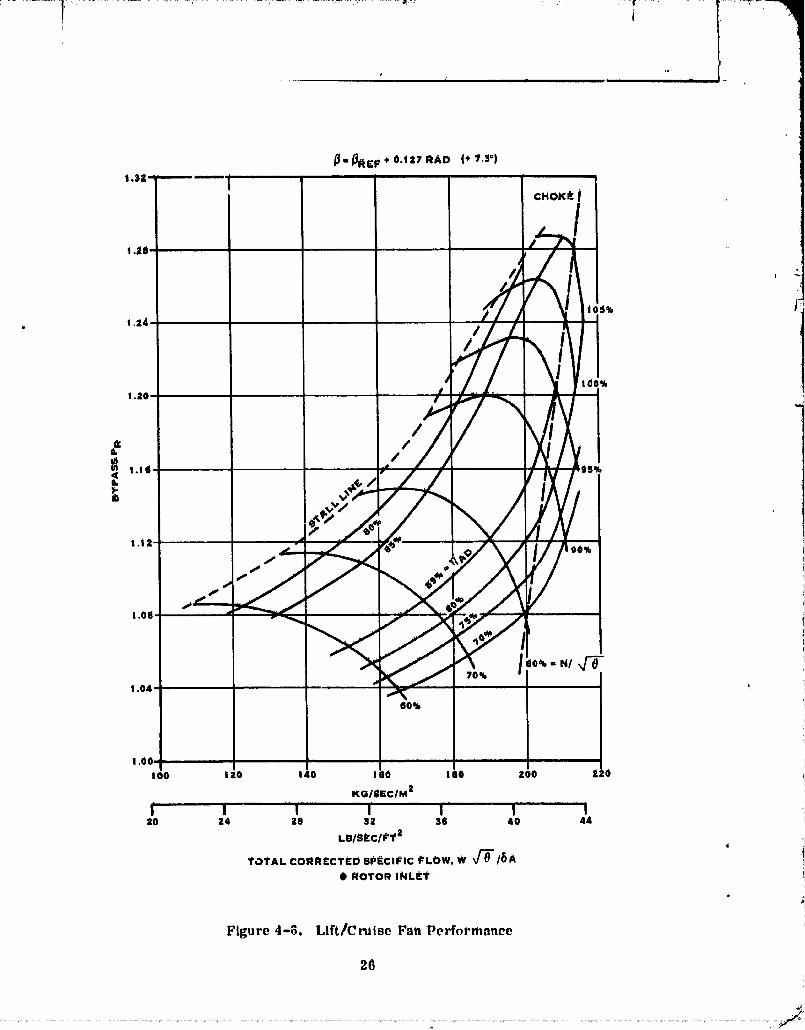
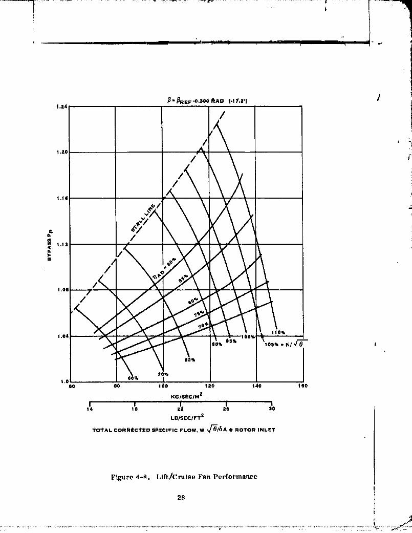
The initial work under this study was to assess the ability of the existing HamlitonStandard fan design to meet the BMAD and McAir RTA performance requirements.Partial fan aerodynamic performance maps which had been prepared for four bladeangles associated With the operational aircraft were expanded from a speed range of95-105% to 60-110% for A blade angles, as referred to an angle of 0. 863 radlans(49.5 °) at the 0.75 blade radius, A_ 0, 0.07, 0. 127, and -0.071 radians (_ = 0°4°, 7.._o and -4.1°). Two new maps were produced to cover 25% to 70%corrected speed for A_ = 0 and A_ = -0.30 radians (-17.2°)• These maps were anextension of an existing design which employed a flow path, shown in figure 4-2, forthe operational aircraft. It was judged that refinement of the flow path from the 9.5BPR of the operational aircraft to the 13. G BPR of the RTA was not warranted becauseit would not signlficantly _fect the maps.
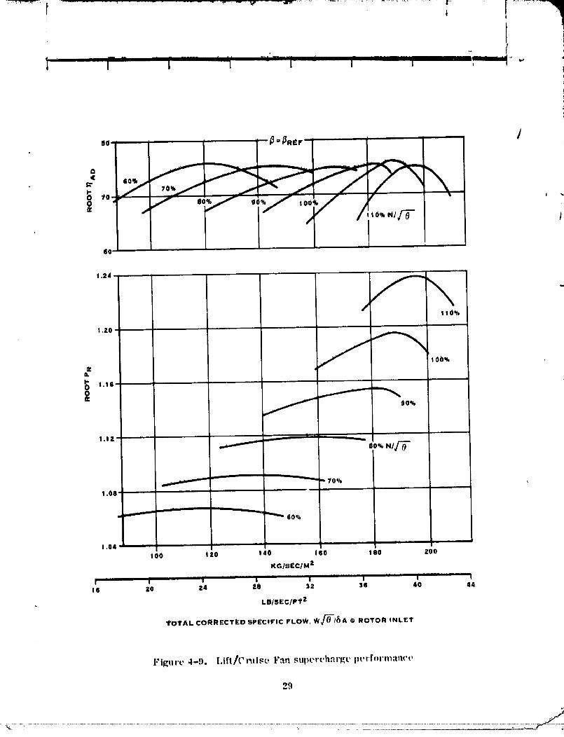
These blade angles were selected based on the fan performance required to meet theseveral operating conditions of the RTA. Fan __ootperformance maps for enginesupercharging were also developed for the _ame blade angles. The fan performancemaps with adiabatic efficiencies, stall lines and choke lines are given in figures 4-3through 4-14. Baaed on the expanded maps, DDA calculated the propulsion systemperformance for both the BMAD and McAir aircraft which is provided in table [l.
Fan aerodynamic characteristics at a fan PR = 1.181 and w _fO/6 A = 176.7 kg/sec/m 2(36.2 lb/sec/ft 2) for the rotor, by-pass starer and engine stator are given in table HI.
20
O0000001-TSB13

T_ble !
F_tn Stage Cha_ae_eri_t_ ,e
, Rotor By_Pa_ Engine JBladet_ Stator_ Statort_
Number of bladea 26 10 87
Airfoil DCA 65/CA 65/CA
ISolidity: tip 0.83 0.83 1.67
root 1.41 1.30 1.85
Thickness ratio: tip 0.03 0.09 0.09
root 0. 12 0.09 0.09
Aspect ratio: tip 2.73 0.75 1.10
root 3.52 0.75 1.10
Radius Hub/Radius Tip 0.425
DCA - Double Circular Art,,65/CA - 65 Thickness distribution on circular arc camber line.
21
O0000001-TSB14

" ....... "7
.... ,_...............,'.......... l_'_ -
, II I ] / I i , , _,
o
II III III , -$
ii I
,,, i i _, i -_ j. I _ /I / /
/ /I /I / / -_I //
-i :;
o ,it I' !r._ -
: iI, !II
.... I .... !
° ° _' ° _, ° $ itNI 0 m _ t
Vi3 'tlllq¥1t
r- .... f i
B3H_Ni 'SrlIGYU i
22!
00000001-TSC01

D [l[ I I' I I I I ...... i _ ,-
1.24-
1.12"
/
1.08" g0%
80% N/'q_i
1.04'
Figure 4-R, lJft/Crui_e Fnn I)('rf()rmnnee
2,1
]
00000001-TSC02

L_m L_
' " ' " rr r ........ t_............ _ ..... i_,, _',,_r ...... I 1 I
_"-VREP
I
ii-J,
;20 40 eO 80 ! O0 I ZO 140
KGIStClmai....... i................I i , ' " i_ , I4 8 IS ! a ZO 24 20 30
.B/S[C/F'T_-
TOTAL C(_RRI_(::'tED _PECIFI¢ PLOW, W, _/'_/_A • ROTOR INLET t
y-r--
Figure 4-.4. Lift/Cruise Faft performance
S4
00000001-TSC03

........._.-_ .................................... _, -r .... _r ............................. ;......... II "_ _..
i! .28
r
! .24 0%
105%
I 20-
1.04 -
60%
25
00000001-TSC04
i
i | •
i_=_RzP+0s2?RAD (+75°)
C_OK_iI
I .;lO- /"_]
|C i_
I
• /// /
¢ '
so% I
1.00,.,
100 1='0 140 160 180 ZOO i 0
KG/gEC/M 2
20 24 ze ]1 aS 40 44
LB/gI'CI_'Tz4
TOTAL CORRfrCTEU 5PI_CIFI¢ I_'LOW. W _'_'/i_A
t) AOTOR INLET
•
Figure 4-6. Lift/Cruise Fan Perfornmnee
26
00000001-TSC05

i
!. "° I
f T '|lf rT I I ............. ]" ................. T"_ m_,l I I _ I I I i
1.3z. l_-_,_eF'0.071 ,CAD (.4.1°)
- _,z8 J
a._4 " [
, \
I.t i _ r _ -
. ,oo ,. ,. ,. ,.o .ooKG/SFC/M z
I I ' I_ .... I IV I ..... I' w16 ZO Z4 ZO 32 36 40 44
, LB/SEC/FT Z
TOTAL CORR£CT_'D SP_'cIFIC FLOW, W_'_ A @ ROTOR INLET
Fil_ure 4-7. I,IFt/Crlli_t, Fnn l_erfr>l'mnnm '
27
00000001-TSC06
| | !L_
i
_,a _RI[F -0._00 i_kD (-|l,r. °) It .24
/
/ ' _tA
i .2o _d'_/ \ r!i
A1.1d "--
N -o, .!
,o, "-_"_::_'G ""'_" '°"'"'_80qk
60 O0 l oo I zo !40 t eo
KO/S_'CIM 2
I w .... i ......... i...... i14 10 1i 11 30
LB/SEC/FT ?"
TOTAL, CORI_ItCT£D SI_r=CIF'IC FL,OW, W %/'0/_A @ ROTOR INLr'T
Figure 4-9. Lift/Cruise Fan Performarlce
i2s t
|
00000001-T8C07
• II'
I - - ' " ...... ' "-'- ................. ..................... ,l(I I I I I i , I -"
6O
! .24 -
110%
I .Z0
e,
(_ 1.16,
._" __°o%
I.I i , ,,
_ 00% N/_"
" 70%
1.08 ...........
i
(10%
i .04 _ .....
100 i 20 140 I $0 ! 80 Z00
KG/SECIM z
i ii • rl ,
16 20 Z4 ;_e 3Z ]iS 40 44
LB/SE.t:/F't 'z
TOTAL COle_RECTI:'D SPECIFIC FLOW. W_'-_-/_A @ ROTOR INLET
Figurv 4-9. l.tft/Cruise Fan supercharge pt, rfornlan(-v
29

90.
60
1.1Z
I .OO ' '
O:ILI.,00E
1.04 ......
40%
a.oo, I ,,,zo 40 eo eo Oo szo
KG/S£C/M 2, ; , ; I'" --i4 8 12 1'4 20 24
LB/SECIP1 "2
TOt'AL CORFIIEC1.tD SPECIFIC FLOW. W _f'O/_A O ROTOR INLEt.
FIl_nr(' 4-10. l,ift/r.l_lse Fan _H)ort, hnrl_e I)erformnnct '
30
00000001-TSC09

tT ...... m .. ..... i-- T |[ .
Ii
r
/ tlo%1.24 , , ,_ /
1.20
/
00I
"_ 80%
_.08
I
1,04 ....... J
80 100 120 14t 160 ! O0 ZOO 2_0
KG/S_C/M 2
I i ....i" i' i I " iZO 14 38 SZ 36 40 44
LB/SE;C/FT 2
TOTAL coFIRECT_'D SPECIFIC; FLOW. W_/f) A @ROTOR INLrT
Figure 4-11. Lift/Crulse F.n _tpt, l'eh,_rge l)t, rformnne_ ,
3]
O(")(')f')f")NN'l_]-_r _n

I III ' " J I I I .............. I ill I I I I ++ _+t I I I I - I I I I !
80. I
]_-_IR_F.+0.1a7 RAO (+7.S")
70 _ L . _ _ _I00_ I,-/ \o! .z8
110%
I .Z4
IOO%
I .zo
=+ j,I-
1.16 _" 90%n,
t .011
_ 6o+.
1.04 ,, ,, i r i
O0 I |0 140 160 I I10 200 ZZOKG/SEC/M Z
20 Z4 2B 3Z 36 40 44LBISrCIFT 2
TOTAL CORRECTED SPECIFIC FLOW. W_'/_-/b A • ROTOR INLtrT
l+'ll_Urt' ,I-12.IJl't/("ruis;t,F.'m FUl)erchar_t" l)t'rf "rmnnt't'
.'12
_ _++++++ + ++ ++i+_
00000001-TSCl I

,,.,.-" /1.20 _
10r%
1.16 1.....
O,
I- 90%0 1.120
80% N/t/0"
1.08. 7O%
60%
1.04 -
00 100 120 140 160 !80KG/Sr'ClM 2
I e 20 24 28 3,?. 36 40LB/SEr/FT 2
TOTAL CORRECTED SPECIFIC FLOW. W t/_ /_A @ ROTOR INLET
FiKtir( '+4-]3. I.ift/('rtlis(, l"nn Ftll)t'r('h,'li'Et, l)t.rf,)rm:m(,t,
:13
00000001-TSC12

1 , 1
I
! ,20-
tlOqb
1.16'
• ii
"_ 80%I[ 1.08 ....eL
00
I[ _TO*k '
1,04' _ '"60%
1.00 '60 80 !00 !20 !40 ! 60
KGISEC/M 2
i iml f_l .....
I w w I ! II _4 le zz =e SO 34
LB/SEClFT t
TOTAL CORRECTED SPECIFIC FLOW, WV_I_A • ROTOR INLET
l"il_lr(' 4-14. hift/Cr, tee V._n_perehnrt_e l)e.rt'ormnnct ,
,14
00000001-TSC13

! i /
t_. It
O0000004-TSC44

It
I"_1I....... _ " t i I I I I
Table III
Fan Aerodynamic Data
Normal T. O./Land Condition-_R = i. 18L Wv_/_A = 176.7 kg/sec/m2(36.2 lb/_ec/ft 2)Aft = -0. 071 tad (-4.16)
%Span R/RT MM MR _ _b p/p T/T Z Df
Rotor Inlet6
5.2 0.455 0.552 0.676 0 20.8 0.992 1.0 - -
51.0 0.718 0.521 0.807 0 9.1 0.992 1.0 - - i95.5 0.974 0.490 0.967 0 2.2 0.992 1.0 - -
Rotor Exit
5.0 0.509 0.526 0.528 35.9 1i. 6 i. 187 i. 064 0. 158 0.41249.8 0.741 0.466 0.620 24.3 7. i 1.173 1.052 0.032 0.34195.3 0.976 0.483 0.792 20.9 0 1.186 1.060 0.073 0.275
%Span R/I-i T MM MA o_ _b P/P T/T Z Df
By-Pass Stator Inlet
7.5 0,651 0, 566 0,632 26.4 0, 8 1, 205 1,060 - -48.9 0.826 0.467 0. 504 22.0 2.4 1.172 1. 052 - -93.9 1.016 0.425 0.460 22.5 3.8 1.186 1.060 - -
B_--Pass Stator Exit
8, 4 0. 678 0. 501 0.501 0 1, 1 1.183 1.060 0.081 0.35951.0 0.843 0.504 ,0.504 0 1.2 1.171 1.052 0.011 0.17994.0 1.010 0.536 0.536 0 -0.3 1.180 1.060 0.041 0.072
Engine Stator inlet
0.8 0.477 0. 463 0.619 41.5 -6.3 1.182 1.065 - -52.9 0. 515 0.494 0.616 36.0 -7.7 1.198 1.963 - -99.2 0. 548 0. 504 0. 607 34.0 -8.2 1.205 1.062 - -
Engine stator Exit
1.1 0.470 0.450 0.450 0 -7.4 1.145 1.065 0.150 0.43551.8 0. 505 0.499 0.499 0 -8.8 1.191 1.063 0.025 0.34898, 9 0,538 0. 472 0,472 0 -9, 0 1. 175 1,062 0,122 0, 381
36
00000001-TSD01
4.2.1.2 Distortion - The V/STOL lift/cruise fan sensitivity to distortion had beencalculated and compared against measurements o._ inlet total pressure digtortioll for aone-fourth scale model V/STOL inlet. The results of this analysis show that the V/STOLRTA inlet total pressure distortion is not likely to induce surge or rotatirg stall of thelift/cruise fan. In addition, limited tests oft a full scale V/STOL fan have indicated that /full scale model distortion patterns are less severe than the one-fourth scale model testsindicated.
Fan sensitivity to inlet distortion is defined in terms of two variables; KR, radial dis-tortion index and K@, circumferential distortion index. The deflation of these indexesare give., in figure 4-15. Combinations of Kit and KO indicate the limits of distortionthat will allow stall free operation of the fan. The distortion sensitivity analysis was t lperforr_ed for the V/STOL fan utilizing: (1) the parallel compressor l_ethod withdynamic stall delay for the circumferential distortion (Ko) and, (2) the performanceprediction program with ring average inlet total pressure gradietits for the radialdistortion (KR). The parallel compressor method Used, iS presented in AIAAPaper No. 74-233, authored by James A. Kern of DDA. The dynamic stall delay cor-rection to the method, as presented, was modified as a result of consultations WithMr. Kern.
The distortion sensitivity calculations were made for a range of circumferential andradial distortion indexes. This analysis yields the maximum allowable valnes of KO |
and KR for stall free operation in the distorted flow field. ]
V/STOL inlet distortion profiles were obtained from Boeing's quarter scale model inlettests. Two profiles of the windward sector of the inlet are shown in figure 4-16. Forthe high specific flow, representative of high power conditions, the inlet flow isattached and the distortion indexes, KO and KR, are low. However, for the low flow,representation of a part power approach to landing, the inlet is separated and thedistortion indexes are high.
A summary of the distortion itldexes for the quarter scale model is shown in figure4-17 for two angle-of-attack/airspeed combinations. The i_Liet separation boundarycan be clearlyseen. b,_parationand highdistortionindexesoccuratflowsbelow theseparationboundary. The conditionswhich were analyzedinthedistortionsensitivitystudyare indicatedby thesolidlineson figure4-17.
The quarterscaleinlettestw_istheforerunnertotheHamiltonStandardvariablepitchfullscaleVP fandemonstratortestingintheNASA Ames 40 x _0'tunnel.AI-thoughthistestisnotyetcomplete,earlyresultshave shown significantlyimprovedinletseparationboundariesindicatedby thedashedlineson figure4-17.
Althot,_hthedistortionmeasurements indicatethatthehighestdistortionindexesoccur Iwithinletseparationatlow airflows,no operationisantlcipatedintheiow airflow 1reg!onbelow theprojectedseparationboundaryforthefullscaleinlet.The two con- i
37
J
00000001-TSD02

II
,
i ' r i " ...........I ' I"-" .........................i "
39
00000001-TSD03

•° /
I' ,r i • t, '1 T-- I I I I I I '_
¢>_= 1.309 RADIANS (75°), V _ = 54 M/s'
(105 KNOTS)
HIGH POWER
UhsP..PAR AI"c-D
i
/I /w_,_,.,o,.o,.,_,,.,.,X \I
i
PART POWER
SEPARATED
I"i_'.re 4-16. I{el)r_'_entnttve l)i,'qm'timl i):lttel'n,_
39
00000001-TSD04

" "+..... "....... +" + --++ .... '_""'_, 1+ "+_'i--,'r,e-+_k
r
I
I TI t i III f .r_1 -_ ..... .........J - , -_ [ I lit 11+I - wt
O.IO-BOEING MOI;)I_L. T_t"
_'UL.I. gCAL[ VP PAN TIk_l'l'
o0. +_"0--'---_ I I
_ O.O0-
Z ihlb£T SEPAl rATION
13_UNDARY
u o.o4. ,,_ ,v S• 4
< io.o,. .
....T_"_"--'-'_---_I.,_= ,llm
,,,sl VOr
0 1.309 mAD. (TS°| $4 MIS 110, KNOTS)
I'_ 11.047 I_AD. (60 °) 64.3 M/S (125 KNOTS)
o.o_1,v
lu ,NLIrT SEPAR ATION
< _ 1..+.,..._+ ,-,- ,o.o,_ ,,.--2.._-_:-_+ .o.,._ -r.o.
+ .....+ + ,+,+,oo,,,,,o,.0 " "80 too ! 20 140 I liO IeO 200 z_,o
KG/S[C/M zi" 'i I*'" 'i .....i....... i f i
I + Z0 24 ='e 3_ I1(i 40 44
Le/S.,c/pl'z
Figure 4=17. Inlet l)isto,%lon[ndices
4t
bt
4.2.1.2 (Continued)
ditions which were selected for the distortion analysis, I.e., maximum control and nor-mal takeoff operation for the RTA, are representative of high airflow conditions.
iIn the high airflow region the inlet sensitivity to radial distortion is more severe thanat lower flOWs due to the fan tip being highly loaded, and sensitivity to circumferentialdistortion is also more severe than at lower air flows due to the characteristic of the
fan speed lines. The calculated locii of KO vs KR for these conditions are shown infigure 4-18. The measured KO and KR values for the appropriate inlet correctedspecific flows are also shown on figure 4-18. These two points fall well within the safe '_operating region for fan inlet distortion, fl
4.2.2 Mechanical DesiSt !
Design _tUdies conducted during 1975 resulted in a fan concept and related weights forthe Boeing V/STOL operational aircraft. The objective of this design study is to refinethe fan rotor concept developed in the earlier studies to meet the requirements of theRTA. Rotor structural components_ i. e., blade disk (cone) and actuator _Vere analyzedfor the RTA operating loads_ including distortion and FOD. Component and systemweights for the lift and lift cruise fans, incorporating the refined rotor, were calculated.
The fan rotor system components are illustrated in figure 2-3.
4.2.2.1 Blade - Preliminary blade analyses were performed to determine blade weight,stiffness, inertia, critical speeds, centrifugal loads_ steady and cyclic stresses,flutter parameters_ and to evaluate possible damage resulting from ingestion of a onekilogram bird.
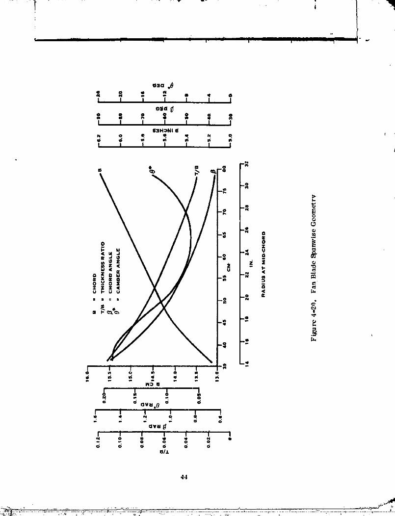
Blade Description - A titanium spar, boron-aluminum shell blade (figure 4-19) wasselected for this application. This construction offers a lightweight design while pro-viding excellent strength and FoD resistance. During the 1975 studies the basic fanaerodynamic sizing had been accomplished and the number of blades, _6, selected forthe operational aircraft. The RTA blade studied has a diameter of i57.48 cm (62-inch)and an average spinner diameter of 72.14 cm (28.4-inch). The average chord widthis 15.00 cm (5.9-inch) and the integrated activity factor (power absorbtion chazacter-istic) is 142 per blade. The blade spanwise geometry is defined in figure 4-20.
The boron/aluminum shell consists of a laminate of unidirectional boron/aluminumtape, diffusion-bonded together with an outer layer of titanium. The titanium skin is aunique feature which provides a corrosion/erosion barrier comparable to that of con-ventional turbofans.
Shell thickness varies from about 0.508 mm (20 mils) inboard to 1. 524 mm (60 mils)over the outer half of the blade. Shell material properties and ply orientations, aswell as spar width and chordwisc location, arc bnsed on design philosophy of ltamilton
41
00000001-TSD06

NOMINAL I"AK£OFF W_6A" tYe.TKOISZClM+(sC+I-tlllZC/wl"z)
,_..o.oTt +tAn(._.P | t
MAX CONTROL. W'_<_ A u 104.3KG/SLEc/MZ|$0.8 LS/_Itcli="P z)
,&_.o.o_ +mAnll.e o)o._-
_ NOM. T.O.
2 ONI"ROI..
m
_ o.o8,
_ PANgTALL
_NOMiNAL "r.o. I
O 0.04 0.08 O.ig 0.t4
K0 • CIRCUMFERIPIql'IAL DISTORI_ION INDEx,'(
Figure 4-18. RTA Fan Distortion SensltivlW
42
___.,_,+__,++ _.+ _:' ;_]+++'++_+....... _+.+ _+ ++++......................+ . ++_+-+ �+_'......++ +.......o +_-+_--+,+°..............+-+--+++_++++++++_+_++= +,+,,,++:-.........._+---+_m , m+ .......+;- ...... _+-+_"_ ++++++_-+
O000000"I-TBD07

i
.......... Ill |- .,Jl I I1 II I ] |
00000001-TSD08
44

r !
- -_ - I- ! JI I
4.2.2.1 (Co_ltlnued)
Standard's successfully tested FeD blade described in NASA report CR-135001. Thespar extends Inboard of the root airfoil region and blends Into ,_ cylindrical sl_ak,compatible with the fan retention geometry. Hollow re_lon_ of the shell, forward andaft of the spar_ are supported with aluminum honeycomb to provide maximum supportfor the shell and increase FeD resistance. A leading edge sheath of Inconel 625 pro-vides continuity across the leadJ.ng edge shell joint, while providhng impact and erosionprotection *.othis portion of the blade.
Natural Frequencies - Blade natural frequencies were calculated for the blade andresults are presented on the Campbell plot shown in figure 4-21. A necessary input
• to the evaluation of fan critical speeds was the fan operating speed range. When thisstudy was conducted, the airframe contractors t studies had not progressed to the point_here they could define the fan operating range; therefore HamiLton Standard selectedan operating speed range of 60-100% as representative of the V/STOL requirements,based on prior experience with V/STOL aircraft. It can be seen that the first mode, 2P,(P - excitations per revolution) critical speed crossover is in the operating range. Asecond mode, _P crossover, also occurs within the operating range close to the maxi-mum operating speed of 369.6 rad/sec (3530 rpm). Higher order crossovers for thesecond vibration mode are considered insignificant because their excitation levels aresmall, they occur at low power, and/or the response of the blade is small. Whilecritical speeds w/thin the operating range arc undesirable, the flexibility afforded bythe composite blade allows the critical speed crossovers to be relocated during theblad_ design to where they will not interface with fan operation.
Steady and Cyclic Loads and Stresses - The blade spar is the main structural member,while the blade shell provides the aerodynamic shape and carries the aerodynamicloads into the spar. To confirm the blade structural capacity the spar was analyzedfor both steady and vyclie stressing. The condition selected for evaluation was duringthe take-off tr.qnsition at 54 m/see (:L05 kt) when both the steady and cyclic loads wouldbe high. The analysis of steady stress considers both aerodynamic and inertia loads.The steady blade loads are summarized in table IV.
Table IV
Blade Steady Load Summary
Metric English
Rotor Thrust 28913 N 6500 lb
Rotor Speed 369.6 rad/sec 3530 rpm
Thrust/Blade II 12 N 250 lb
Blade Centrifugql Loads lll, 200 N 25,000 lb
.t5
_- _ ......_................... _o .. o,;....... :,..........................;,...... _o......... _........ .... :._,- . ...........
O0000001-TSDIO

IIlI
' Ill I I i I ! ! I T _fL_ . / lit .......................... i, I -
4fi
O0000001-TSD11
I
4.2.2.1 (Continued)
Cyclic loads affecting the blade due to a once per revolution (lP) load variation werecalculated for a separator1 fan inlet, as this was believed to be the worst case whichcould be experienced during transition. A separated inlet distortion profile obtainedfrom Boeing inlet distortion testing was used to calculate the velocity profiles shownin figure 4-22 and input into the llamilton Standard multi-ar4muth blade airload calcu-lation program. The multi-azimuth program calculated radial airload distributions ofin-plane and out-of-plane loads at a once per revolution frcqa_ncy. These rotationrelated loads Were then used as excitation loads for a vibratory stress program. The
lP flat'wise blade vibratory bending moment was calculated to be ± 99.42 N-M (_Ss;0 in. -lbs) at the 45.72 em (I.8 inch) station. The lP loads were increased by 50% to accountfor loading at multit}h_ integers, I.e. t 2P_ 3P, 4P etc. The resulting moment of 149.13
• N-M (1320 in.-lbs) was used to calculate a cyclic stress on both thL:pressurc side andsuction side of the spar.
These steady and cyclic stresses are related to spar material design fatigue strengthfound on the Goodman diagram presented in figure 4-23. A stress margin in excess of1.0 exists for both points indicating sufficient spar strength at the most highly stressedstation.
Blade Flutter - Fan blade bending flutter was analyzed to insure that the V/STOL fanblade would not be susceptible to large deflections clue to momentary high air loads.
Blade flutter is brought on by the lower torsional rigidity of thinner blades. Sincethe center of pressure on an airfoil is near the quarter chord point, there will be sometorsional deflection (twisting) of the blade tending to increase blade angles. If thisdeflection is large enough, the airfoil angle of attack will be inere'_secl to the pointwhere the airfoil stalls, the air load drops, and the blade unwinds and returtls _o itsoriginal pitch and the cycle starts over again. If the blade is torsionally flexible enough,ciestructive vibrations will be set up.
Preliminary calculations were made to examine the bending and torsional flutter para-meters of the V/S'IOL fan blade. Flutter parameter limits have been determined from
design cx'pcrience and development of many propeller and fin designs. The establisheddesign guides reflect conservative limits that will provide a fan blade design free fromcritical flutter properties. This analysis assessed the blade as having an adequate beaci-ing flutter parameter with 36% margin. The torsional flutter parameter was calculatedhaving a value 15_,'_below the design allowable. Torqional L'lutter is depcndt, nt on bladetorsional frequency which is a result of blade structural characteristics. Thc detail de-sign of the blade will provide local changes in the blade structure in ordt, r to increasethe torsional frequency to bring this parameter to within acceptable design guides.
.17
" ° -0000000i-TSD12

r j I
j ! ! I" "
"0 --0
o o 0 0 0 _ 0 0 0
S/_
0 0 ¢) 0 0 0 00 o 0 0 0 0
• 11_0"13_ "lV IXV
4N
00000001-TSD13

i
t
_11 1_ _'_ _ ..... "TF .... -- I I .... "'
00000001-T,SD14

/"- _ "-[ ..... - ......................... i mm -i I - i--_ | ................ ! • - " - • ............ _ ._l _,_
4.2.2.1 (Continued)
FeD Analysis - The blade construction selected by Hamilton Standard for the V/STOLblade design has been experimentally demonstrated to have adequate impact resistance
under beth NASA and I_SAF contracts. Impact stressing associated with the fan blade /for the V/STOL application was calculated and compared to impact stressing of ex-perimentally tested bladcs to validate the V/STOL blades FeD tolerance.
The FeD resistance criteria for the Navy V/STOL operational aircraft Is tolerance of1 kg (2.2 lb) bird ingestion. This criteria was also adopted for the RTA fan. Stress-ing was calculated for the RTA fan blade using an impact analysis method developed byHarmiton Standard. This analysis Indicated _hat stressing would be similar to thatexperienced by a boron aittminum composite fan blade tested at Hamilton Standard forNASA LeRC as reported in NASA CR-135001 and damage would be limited to minorlocal damage at the tip traiiitlg edge. In the analysis of the 1 kg bird_ the impactlocation on the blade was assumed to be at the 0.80 blade station. The values used in
the analysis are listed in table V.
The impact analysis program treats the bird as though it were a cylinder. Bird dimen-sions are calculated for length to diameter ratio of 2, and an average bird density of679.0 kg/M3 (0.02453 lb/cu, in.). The relative impact velocity is determined from
vector ad_hion of the bird inie_ velocity (equal to the aircraft forward velocity of
51.44 M//S (100 knots) in this case)_ and tlte tangential blade velocity due to rotation atthe impv/ct radius. The bird longitudinal axis lies normal to the relative impact veloc-ity vect/br. The maximum slice width is calculated assuming the cylindrical end of the
bird n_rroWly misses the leading edge of the adjacent blade. The slice thickness be-come,.j..._..dependenton the blade spacing times the sine_,,of the angle betweel_ the relativeimpa/_t velocity vector and the rotational velocity _ector (figure 4-24). Tile bladespat/lag, in turn, is dependent on the circumference at the impact radius divided by thenumber of blades. These calculations result in a slice width of 3.30 cm (1.30 in. )or an equivalent mass of 167.8 g (0.37 pounds).
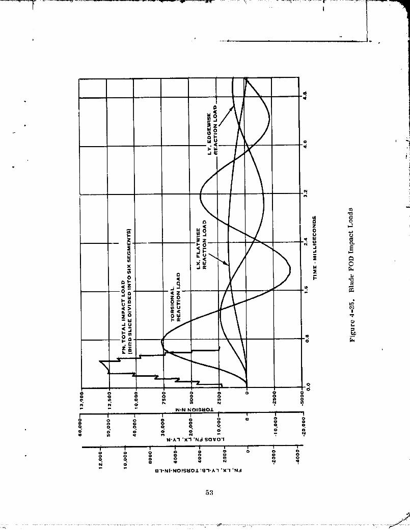
The cylindrical bird slice is divided into six equivalent rectangular segments, whichimpact the blade. The computerized analysis treats these seg'merits as fluid Jetsimpinging upon the pressure side of the blade and reacted by the blade inertia andstiffness. Time histories of impacting load, as well as blade reaction loads in the X,Y, and torsional directions, are calculated by the program. Corresponding timehistories of three basic deflections, X, Y, and _, at the impact site are also generated.The X-deflection is taken parallel to direction of the blade natural flatwtse mode ofvibration, with the Y-deflection (primarily the edgewise deflection) normal to X. Thetorsional deflection is taken about the blade center of torsion at the impact station.Impact loads are determined as the forces required to turn FeD segments (treated asimpinging fluid jets) through the impact angle. The time histories of load and deflectionat the impact location, calculated and plotted by the computerized analysis, are shownin figures 4-25 and 4-26, respectively. The maximum de5ection is in the fiatWise (nor-mal to surface) x-direction amounting to 7.37 cm (2.9 inches) at approximately 2.4mllli-seconds after initial impact.
50
I
00000001-TSE01

|
! | | '
P/
Table V
FOD Impact Parameters Summary
Metri_.__c Englt_h /
Bird Characteristics
M_ss 1 kgm 2.205 [bs
Density 0.679 grams/era3 0.02483 Ibs/cu. in. ,
Length 19.576 cm 7.707 in.
Diameter 9.789 cm 3.884 in.
Coefficient of Restitution 0.0 0.0
Blade Parameters
Radial Impact Station 70.21 cm 27.64 in.
Angle of Impact Station 0.62 radiafls 35. 6 deg.
Blade Spacing 16.97 cm 6.68 in.
Damping Coefficient (same for all o, 12 0.12vibratory modes)
Angle of FlatWise Mode (X-axis) 2.647 radians 151.7 deg.
Angle of Edgewise Mode 1.141 radlans 65.4 deg.
.Impact Parameters
Rotational Velocity Component 259.5 meters/see 851.4 ft/sec
Fwd. Velocity Component (I00 knots) 51.5 meters/see 168.9 ft/sec
Resultant Relative Impact Velocity 264.6 meters/see 868 ft/sec
impact Angle 0.43 rad 24.4 deg.
Slice Si_e 3.30 cm 1.30 in.
Silce Weight 167.8 grams 0.37 lbs
51
00000001-TSE02

"I_............. r " _ ],if ................. I-.,I" I I !
Figure 4-'_4. FOD Impact Geometry
52
00000001-TSE03
I
"d
m
,=., "_ .
O- ",_
.Ju _<3
____ _ ,.t---- '
00 0 0 0 0 0 0 0 00 0 Q 0 0 0 0 0
,_" _, o r, N _, _," " " IN-N N OlggO.IL
j...... , i , I , _ I0 0 0 0 0 0 0 0 00 0 0 0 0 0 0 0q o q o. q o o o0 0 0 0 0 0 0 0
N-A'I 'X'l 'N.'i SOVO'I
0 0 0 0 0 0 0 0 00 0 0 0 0 0 0 00 0 0 0 ¢) ¢) 0 0
8"I-NI'NOISBOJL '8"1"A'1 'X'l 'N.'I
5.']
00000001-TSE04

54
00000001TSE05

L!'IT T i-" ..... - , , , "TT " ._.
4, 2, 2, 1 (Continued)
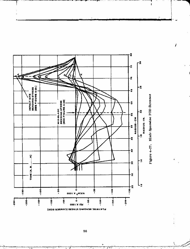
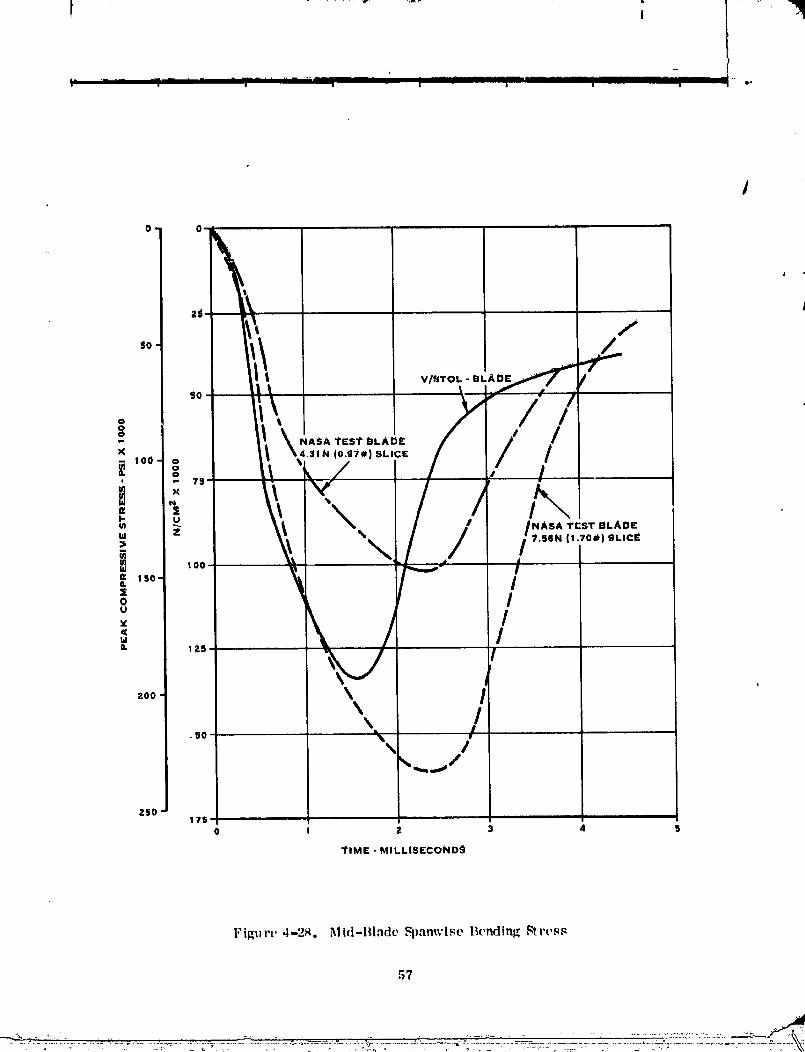
This deflection in the fl_ttWise direction results in peak spanWise bending dtre_seS attwo locations along the blade sp_m. These are generated by a second portion of theprogram which calculates the perturbation along the length of the blade due to locall_-ed impact. The spanwise stress distributions are caiculated at specific time incrementsafter impact and are plotted by the computer program in figure 4-27. As can be seenfrom the plot, there is a peak mid-blade bending stress of about 131 kN/cm 2 (i90 ksi)at the 55.88 cm (22-inch) blade radius, which is a con,pressive stress on the suctionside. A second peak of 158.6 kN/cm 2 (230 ksl) (a tensile stress on the suction side)occurs in the vicinity of the impact site.
• Time histories of stress at both peak locations are plotted in figures 4-28 and 4-29Which also show comparative calculated curves for various impact conditions on FOD-tested, similar blades. The amount of calculated stress correlates with the degree oftest damage occurring on the NASA test blade. Analysis of NASA test blade indicateddamage for a given object would be comparable to damage on state-of-the-art titaniumblades. Non-destructive inspection of the test blades showed that further operation waspossible.
Calculation results, as shorn1 in figures 4-28 and 4-29, indicate that stressing will becomparable to that of Hamilton Standard's boron-aluminum blades tested for NASALeRC. The test blades experienced only minor damage to the trailing edge tip andwere judged suitable for continued operation. Further improvement to the blade FODtolerance is believed to be possible through refinement of the blade geometry duringthe detail design.
4.2.2.2 Disc Assembly - The disc assembly consists of the blade retention bearing,seal, pitch change trunnion and the disc itself.
Loads - _he blade loads that act on the blade retention bearing and hence the disc arelisted in table VI. (Max control condition)
Table VIBlade Retention Loads
Blade and Attachment Centrifugal Load = 133, 440 N (30, 000 lbs)
Steady Bending Moment = 359.6 N-M (3183 in.-lb)
lP Vibratory Bending Moment _ 279.8 N-M (2477 in.-lb)*
NP Vibratory Bending Moment 139.9 N-M (1238 in.-lb)
* These are total loads at the 12.5 in. station in the retention
_.nd are therefore higher than those used for the blade.
55
00000001-TSE06
,5(;
O000000"I-T,SIE07
•- /............................ ..
O*
V/_TOL. - BL
O
- _ \._sAt_A_ / i /
, o [h
,', _ \\ "\ / t ,"_, _ _ _ I ! /,,ASAT,'sT.LAD,'
"," 'I, "\/. ./ ,/'"'""°"'"°':,.o; _ r-" ,'o I
° \ /ta ,
\v_oo \ /
\ /\
Z50|75 ....
2 3 4 5
YIME - MILLISIECOND9
'_ Mid-lHade Fpanwise Bendin_ Stres,_Fil_ure ,-I-,_.
57
..... ::-:L_:::]
00000001-TSE08

ZgO--i
V/STOL BLADE
t00--
NASA TEST BLAI_E(|.70#r) ltLlC£
/ // ',: '"":,,,- ///i' 1-- I 4.ilN
J i00--
80--- /f' _ NASA 'lEST EILAO _"
, % IO.S_e)SLIc£
/ _ ,.do.
, i
0- 0 0 0.5 1.0 I ._ l.O
TIME • MILL, IS£CONDIt
Figure 4-29. FOD Impact Station Spanwisc Bending Stress
58
----.--_ ,-........ _ ............ U'.'"" ": .......... "":,;7::- _': ..... '......... -".... '-:-........ "-:............ " <" '
00000001-TSE09
_-_= _ +_-'_r --+_ .................. ! •
"" t
' I 'ml iT][ I]_ _ TT _IT ....... I o I -I .,
4.2.2.2 (Continued)
The requirement of variable pitch necessitates tJ_e use of a round retention and the
inclusion of an anti-friction bearing. The retention that was selected for the V/STOLis a configuration that has been in service for rno_'e than six years and has success-fully accumulated over one million flight hours. It is an angular contact ball bearingwith an integral outer race in the steel disc and a split inner steel race on the titanium
blade spar. The outer race is induction-hardened to RC 56 minimum in the region ofthe ball contact. The inner race is through-hardened to RC 56 minimum. Ball-to-ballcontact is prevented through the use of separators.
The proposed lubrication system for the blade retention bearing consists of an ion-. sputtered moly-disulfide (MOS2) coating on the races and bails. The retention bearing
dimensions arc listed below:
Pitch din. -_ 5.7099 cm (2. 248 in. )
Ball dia. _ 1. 270 cm (0.5 in. )
No. of balls 13
|nitial contact angle 0.3698 to 0.6136 r_d (21.19 to 35.16 deg)
With the above dimensions and loads, the retention bearing was analyzed.
The results are plotted on the contact stress Goodman diagram on figure 4-30, showingthe relative position of calculated stresses and design allowables, and on a blow-up ofthe pertinent area on figure 4-31+ with plots of previous design experience. The reten-tion bearing stressing is satisfactory and within prior experience levels.
Dis......_c- The single-p|ecc disc concept, which has been utilized in ltamilton Standard'spropeller and fan designs for nearly 15 years, will also be used on the V/STOL applica-tion. Steel, which has been the selected material for all previous designs+ has been
selected for the V/STOL application. Discs for variable-pitch fans havc generally beendesigned for stiffness rather than strength in order to provide the retention stiffness re-quired of a blade without part-span shrouds.
The disc is a fully machined component made from a D6AC vacuum melted steel forging.It is heat-treated to a hardness of RC 40-44 except in the blade retention area where itis induction-hardened locally to a minimum hardness of RC 5(;.
The stresses in the disc have been determined by a combination of ring, beam, and shellanalysis methods. Partial stresses arc calculated by each method due to different typeloads and then added to determine the combined stress for various stations on the disc.The critically stressed area is the disc ring at the blade eenterline. Tile loads imposedon the disc are the centrifugal force of the rotating disc by itself plus the steady and vi-bratory blade loads listed earlier. The normal bentting and hoop stresses were calcu-lated for each of these load eases and combined for a total steady stress plus and minusa total vibratory stress. These stresses are plotted on a modified Goodman diagram,fi_,mre 4-32+ along with stress levels of several, recent applications. The disc designstresses are below the design allowable limits conl irming an acceptable design.
.r_9

I o II
i
T i I jl I a_ I i .......... -lit• " T i-I I I I I
60J
00000001-TSE11

V j I
r I I' . J___ . i I II I i- ..
0
/
HI
-x.___ " " _• _ -_,,, -.......... _ _':'_. _,,. ,'_,_-- ,, ..... ,_ - . ._: .... -_..-__
O0000001-TSE12

f i II
* . . J , .... I . . I i " -'
o,u
!
w._O
EE
> B.
a 81<
- _ .
i :°/ i• _*
0 Z
0 :,
o dul
.I
a
Nu
w
0 >
.IIdn,
SS3HJ, S :)I'I:_A:::) 3AIJLV'13U

Y
i
, . I, , J iI I ..... I III " I'
4.2.3 Plteh Control ,q_stem
The _lteh control system draws heavily on proven concepts utilized on current aircraftapp!ieatlons. The pitch change concept was selected during the 1975 studies to provide
the light weight, high reliability and _afety necessary for a primary flight control /system, It provides both hydraulic and mechanical redundancy to allow continued opera-tion in the event of a hydraulic failure withir_ or outt_ide of the fan system or the failureof seleet,_d structural components.
The pitch change system employs a duallzetl linear hydraulic actuator that incorporatesboth hydraulic anci structural redundancy. The actuator as Illustrated in figure 4-:3:1,is supported by the cllse anti connected to the blades by mechanical links. It -ilso in-eorporateg a splined torque restraint which removes circumferential loads from theblade links.
The control system which was defined by the 1975 design study (s illustrated by theschematic presented in figure 4-34. It is powered by two independent aircraft hydraulicsystems. Each system provides hydraulic power to one cylinder of the actuator via abeta regulator and transfer bearing. The beta v'egul'ttor incorporates "m electrically-controlled hydraulic serve valve (EHV) to modulate pressure to the actuator and asolenoid operated bypass valve to isolate the fan from a given hydraulic system in theevent of a control system failure. Triple reclundant electrical feedback is providedby linear v:u'iable displaeemcnt transducers (IA'IYI') attached to the actuator feedbackarm,
Control system operation is monitored by a shutdown-abnormal-system (figure .!-34)which analyzes EIIV position sensed electrically by LVIYF's, hydraulic actuator posl.tionsensed by a triple-redunclant LVDT, and a EIlV comparator tootle!. The shutdown sys-tem detects a control system failure and isolates the I:mlty hydraulic system via thesolenoid-operated bypass valve,
The pitch change system eharaeteristic, s are described in table VII.
Table FIt
Pitch Change Charaeteristies
!"ime Constant. 0.1 second
Pitch Change Rate: 1. 715 red/see {100 ° !second)
Blade Angle Range: -0.5235 to + 1. 5705 rad (-30 ° _90 '_) l'ron_,lcsign point
Flow Requirements: 0. r;9 liters/see (11 g'pm) per hydraulicsystem maximum fh)w rate at 20[;_.I N/rm 2(:3000psi).
O000000"I-TSE'I4

1 i I l I- I I I I b,
I{4
00000001-TSF01

,o
I- _ ! I I I q'_

l
i ....... "° ........ i[ II 'I ' _........ _ , • '* I- --_" ' ....... * ..... IIII .I ' i , i ,
4.2.$ (Co_tinUed)
Elements oftheactuationsystem were analyzedforst_'ucturalcapacity.The actuator1cadsare developedby thebladesand are theresultofcentrifugalloadstendi_ torotate blade mas_ elements into the plane of rotatlonj retention friction and aerody_amlcIoadings. Because no load spectrt_m was available from the airframe cogtractor_.loads were calculated for Imown conditions which could produce the maximum stressand an associated number of cycles assumed. TheSe load conditions are presented intable VTII. The actuator piston a_d cylilldor were not allal_ed, but the componentgeometries _vere scaled i'rom an existing similar design for the XC-i42 main propel|er.During i{s design, the XC-142 propeller aettlator was a_lyzed for load condltloris simi-lar to the V/STOL fan.
Table VIIIActuator Loads
Load per Blade
Condition Steady _
$tart _ Stop -60 N-M (-525 in.-lb) _=50 N-M (_:525 in.-lb) 2 x 10⁴
Hover -80 (-712) + 27 (_:239) 108
1 P -92 (-814) _ 21 (± 186) 108
Bird Strike 273 (2420) + 926 (+ 8200) 1
Actuator elements which we _ - _nalyzed include: blade link, blade pin, link support,torque restraint and center roa support. In all cases it was determined that the birdstrike load determined the required structure. Table IX summarizes the results ofthe structural analysis.
Table IX
Actuator Design Margins
safetyMargin*Item (bird strike)
Link I. 25Pin 1
Link Support 20Torque Restraint IIActuator Center Support (bending) O.005
*Safety Margin = Allowable Stress 1Actual Stress "
66
00DD0[ NI-T n'

i
•* [
- ; o,
4.2.3 (CoNtinued)
In all cases the member maximum stress during a bird strike is less than associatedmaterial design allowable. This assures a conservative design of the pitch controlsystem, which will function satisfactorily during all modes of operation.
4.3 SYSTEM WEIGHT SUMMARY
The fan rotor is common to both the lift-cruise and lift fans. Mass_ as tabulated J
below, were calculated for all rotor con_ponents,
tCompone nt Mas s
Blades (26) 53.07 117 lbs.
Disc 50.80 112 lbs.
Spinner 12.7 28 lbs.
PitCh Change Actuator 29.03 64 Ibs.
145.60 321 Ibs.
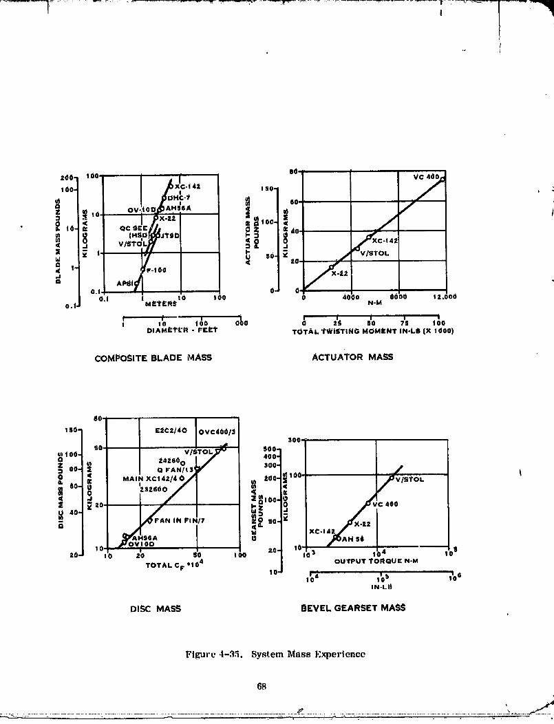
Weight for the gears and bearings were calculated during the gear study described insection 5.0. The gear weight_ resulting from this study are conservative becausethey are based on a structural analysis which assumed that the gearing would carrythe maximum control power for the full life of the gearing. This was done because atthe time of the study no time-load histogram of this data was available from the air-frame contractors. The gear and rotor weights were combined with the weight valuesfor the remainder of the system as calculated during the 1975 study to provide weightfor the lift and lift-cruise fan shown below. Figure 4-35 provides a comparison ofV/STOL design weights to actual weights of similar system components which havebeen fabricated for other applications.
Fan System Mass
Lift-CrUise Fan Lift Fan
(kg) (Lbs) (kg) (Ibs)
Rotor 145.60 321 145.60 321
BetaRegulators(2rcq'd) 4.99 11 4.99 II
Gear Reduction 186.88 412
Fan Case 121.11 267
Total 150.39 332 ,t58.58 10! 1
67
00000001-TSF04
I
80- )
'" °° ,'+ 7100. -|42 150- +I_DHc-i
,,. oo,,.,. ,oo._,o. _11v/s,oLM o xc.,,_
= / _ "" _=0. ../ OL
_ '" ,F-,oo /_,,° tm APs_I0.1) 0- 0,
0.1 ! _ ,o 0 4¢ )o _c_)0 I 2.I,O0o.1, M_C;R'_ N-M
' ' ,_o &o _ ,'_ ,'o ,'. ,o'oI IODIAMe_I"L'I_ - F£_:1" TOTAL _'WiSTING MOMI[NI" iN-LB (X 1000)
COMPOSITE BLADE MASS ACTUATOR MASS
dO.
I SO- ¢2C2/40 OVC4001_300,
50. V/STOL..,_ $00-
i '0° ,,,.ooL/ ,0o4MAIN XCl 4Z/4 O/ )00 100I vISTOL
,°- _,,,ooI :, ,
N IN PIN/7 _ SO _
C-I
_YAI_56 A
I 0 _OV_ 00 Z0] :01_
ZO- 10 20 SD I00 10S
TOTAL CF *104 OUTPUT #ORQUE N-M
I 4 IW0_ I 6IN-LB
DiSC MASS; I_EVEL GEARSET MASS
Figure 4-35. System Mass Experience
68
00000001 -TSF05

[I
-- ¢ • |_ .,
4.4 BEVEL GEARING STUDY
A bevel gear arid cross shaft drive assembly is associated with both the lift and lift-crttise fans. During the 1975 studies, the cross shaft drive angle was 90 ° for both thelift and lift-cruise fans. It was intended at the onset of ti_s program to evaluate thecross shaft drive systems with the objective of establishing commonality between thelift and lift-cruise fan bevel gearing in areas such as mounting arrat_gement, bearingtype, size and placcmerLt. However, airframe studies had shown that the cross shaftdrive angle for the lift fan should be different from the 90 ° angle for the lift-cruise fan
• eiimin_tting the possibility of commonality. Study efforts were therefore directed atestablishing a lift fan bevel gear mounting configuration having the lowest weight andbest reliability.
J
• Several tapered roller and roller-bail bearing eo_igurations were evaluated for thegear arrangements shown in figure 4-36. Bearing loads were calculated for the fanand gearing data shown below.
Gear Ratio 3.33
Pinion 27 teeth
1231 rad/sec (11755 rpm)
Gear 90 teeth
370 rad/sec (3530 rpm)
Pitch 4.0
PressureAngle 0.436rad (25°)
Spiral Angle 0.436 rad (25 °)
In addition to the gear loads the tail shaft bearings carry the fan loads shown below.
22895 N (5147 pounds) at maximum thrust
15746 N (3540 pounds) at mean thrust
443.3 N-M (327 ft-lb) lP moment
1436 N (323 pounds) side load
Bearing loads were calculated for each b_aring type and mounting configuration. Bear-ings were selected based upon catalogue sizing which would provide a 1500 hours actualB10 life based on vacuum-melt factors (life improvement factors due to higher cleanli-ness of the bearing material) of five for straight and tapered roller bearings and 10 forbail bearings. The loads and bearing weights are summarized in table X. For the inputpinion configuration I, utilizing two tapered roller bearings was selected because it of-fcred the lightest weight and most reliable system for the 1500 hours B10 life (2 bear-ings vs 3 bearings). For the tall shaft bearing configuration II[ also using three taperedroller bearings was selected. It, too, was selected [or light weight and reliability.
fi9
00000001-TSF06

D/_IV£ SHAFT
PINIONBEARINGS
INIO
FAN _t.
BEARINGS
Figure 4-36. l,ift Fan llevcl Geal' Assembly
7O
00000001-TSF07

. _..d
00000001-TSF08

__ --- -- _ nlr-"...... " t,I' w I
SECTION 5.0AIRFRAME AND CONTRACTOR SUPPORT
. In addition to the interface activity described in section 3.0, detailed information gen-erated during the preliminary design study was provided to MeAirt BMAD, and DDA. 4
This information consisted of the following:
- Fan performance maps (6) for five blade angles at speeds ranging from 20%to 110% speed.
- Supercharging performance (6 charts) for five blade angles and speeds rang-ing from 20% to 110%.
- Component weights (Section 4.3).
Program planning data consisting of costs and schedules for the engineering, develop-ment and hardware associated with a two aircraft RTA program was also provided toDDA for their use under NASA contract NAS 3-20034.
Late in the study_ MCAIR requested that the feasibility of a reduction in fan bypassstator exit Mach number be examined as a means of improving the gross thrust coeffi-cient for the lift-cruise fan nozzle. High fan exit Maeh numbers are inherent in lowbypass fans when operating at high specific flow because of the lower density of thebypass air. Reduction of the Mach number by diffusion within the bypass nozzle wasnot possible because of the close proximity of the stator exit to the nozzles•
MCAIR's objective was to decrease the stator exit Mach number from the currentvalue of 0.51 at take-off condition to about 0.30. A study was made to examine a Machnumber reduction by means of diffusion through the bypass stators. The flowpath wasmodified and the stator solidity was increased producing a reduction in Mach numberto about 0.40. However, there was a corresponding reduction of 25% in the fan stallmargin and an efficiencyreductionof2% atthetake-offand maximum controlcondi-tlons.
While thisapproachto reducingstatorexitMach number appearedfeasiblejithas notbeen used inany previousappllcaUonsand couldbe a technicallychallengingapproacbtoimplement. Therefore,additionalstudieswere made toexamine alternatemeansofreducingthestatorexitMach numbers. These studiesincludeddiameterchanges_reductionin therotorbladerow convergence,increasesintherotorspeed,moderatechangesinthestatorexit-to-inletarea ratioand raisingoftheoperatingline(reduc-tioninthefannozzlearea). Each of theseapproachesart,attemptstoincreaseflow
73
_" _ ,,9 • °
...... -: " , .... l li ii ii ll Jl II IN --i.]ikJ_

5.0 (Continued)
area or reduce airflow with operation at higher fan pressure ratios with acceptableblade row diffusion factors. It _vas found that the stall margin loss was more rapidwith these approaches than for diffusion through the stators.
It was concluded, therefore, that while technically ehallengtug, diffusion through thefan exit stators was feasible and the best approach of those examined to reducing thestator e_tt characteristics.
The res,dts of this work were discussed with McA/r who concurred that further workin th/s area was unwarranted.
To support the lift fan drive train mechan/cai design, the power to drive the fan duringtransient start-up operat/on was analyzed.
The V/STOL propulsion system is designed so that the lift fan will be stopped duringconventional forward flight. The lift fan drive train will contain a system to open thedrive train channel so that power will not be tra_mltted to the lift fan. There aretimes when the lift fan will have to he engaged after the input drive system is alreadyat governed speed, Such as an approach to vertical landing. 'b_flle engaging the liftfan, the coupling device will have to accommodate a speed differentl_fl betWeen theconstant speed input drive shaft and the nonrotat/ng lift fan.
Figure 5-1 shows the power required throughout the start-up speed range. The indi-cated power is the steady state poWer required to drive the fan at the indicated rota-t/onal speed. Some additional power will be required to accelerate the fan dependingon the acceleration rate.
74
O0000001-TSFIO

b,,
0 0 0 0 0 0 0 0 0 0 00 0 0 0 0 0 0 0 0 0
bi
>,a
0 0 0 0 0 0 0 0 t0 0 0 0 0 0 0q N 0 CO W q N
dH _i3MOd .L-iyHS NV.'I
75/7(;
."",, ' . .o,:. _.......:, ..... . _,' o. . .o,,. i_j o o ,, ° ,.' , ,,_°,. --7_,,-...... ;'
O000000J-TSFJJ

I t I
i
'" i
• I n i- ,.
INTERFACEDEFINITION
FOR
LIFT/CRUISETURBOFANENGINE COMPONENTS
NASA/NAVY V/STOL RESEARCHAND TECHNOLOGYAIRCRAFTPROPULSIONSYSTEM
HAMILTON STANDARD DIVISION
UNITED TECHNOLOGIES CORPORATION
DETROITDIESELALLISON DIVISIONGENERALMOTORSCORPORATION
JULY 1976REVISION "B" JANUARY 1o77
R. M. LEVINiANHAMILTON STANDARD
S. M. HUDSONDETROITDIESi.LALLISON
7717_
- -"_ ,_ ' ° " ° ,"" o°,...... " ,....° ° " , , o '_ .....,_L "
O0000001-TSF12

CONTENTS
I. INTRODUCTION
II. GENERALDEFINITIONS AND RESPONSIBILITIES
III. REFERENCEDRAWINGS, DOCUMENTSAND SPECIFICATIONS
IV. INTERFACEDEFINITIONS
t
79 f_N
,i
........ "..,.,,
_,, , b" '" "'-"//"_"_"........_ _ "....._-_ ................._- "_....: _" o_ _ ' _ .... ,,.... i'_ _
00000001-TSFI3

I " ' "' , ..... J- J I ' y T i ' "'
I, INIRODUCTION (REVISION B)
The Hamilton Standard (IIS) D_vls;onof United Technolo_llesCorporation and tile DetroitDieselAllison (DDA) Division of General Motors Corporation are engagedh_conceptdolinltlon studlesof I_ft/crui_e propulsion syslemsfor o NASA/INg,O,V/STOL re_e_,fchalrcraft under NASA contracts NAS3o19414and NAS3-20033 wlth HS, and NAS3-20034wlth DDA. 1F.eseconlracls require that the, interf_c_.._between the HS fan compone,_lsand the DDA engine componentsbe.defined. This document definesthe interface detailswhich have beer, iclentified to date and the responsibilily for componentsresulting fromthese_nterfacedetails.
The refinement of details of the interfaces between the HSand DDAcomponentsdefinedherein will be recorcled in revisions to this interface definition documentas the programprogresses. Any major interface ct.angesfrom this documentshall be identified in writingto the NASA Project Manager.
Th.ellft fan intel'face defin_tlon agreed to between the airframe contractorsandHamilton Standardas part of HS's work under Contract NAS 3-2C033is incor-porated into this document asAddendumA.
!_{" ..... T '_ _ ".. _............. _;"_"._i::_ :',:_*_ --;' _"_ o _ " • _ - , :;,...... ,,, _ _'_ '_!'_
qp
O0000001-TSF14

II. GI_NERAL DEFINITIONS AND RESPONSII_II..ITIES(REVISION A)jJ . im i _ .i
tThe v/STOL ptopulslon systemc'onSistsof two turbofan engine.% a temote Iifl fan andthe associated gearing and shafting required to couple these components. Identicalvai'iable pitch fan rotors are usedin the turbofan enginesand the lift fan. Thisdocument deals with thu interface between the Hamilton Standard variable pitch fanrotor and the Allison turboshaft engine, gearbox assembly and fan flame and case,which together form the turbofan engine
DDA is responsible for the gasturbine componentsand the resulting complete turbofanengine. Hamilton Standard is responsible for the single stage variable pitch Fanandthe actuators and controls associated with blade movement. Thls fan responsibilityincludes defining the overall fan stage performance and operating envelope, andproviding the aerodynamic definition for rota'ting and stationary componentswithinthe stage. Hamilton Standard is also responsible for all mechanical componentsandfunctions of the fan rotor assemblyand will therefore coordinate the aero-mechanicaldesign. DDA will be responsiblefor the mechanical design of the stationary fancomponentssince these will be integrated into the turbofan engine forward frameStructure.
Signals for the positioning of the fan blade may come from the engine Fuel control andthe aircraft flight control. Hamilton Standard _sresponsible for ihe componentsrequiredto condition these _gnals and convert them into blade angle settings on the variablepitch fan rotor. DDA will provide the power in the form of hydraulic pressureand flowfor usein the HS actuators. The gearing, lubrication, accessory drives and aircraftstructural interfaces are the responsibility of DDA. Overall lift/cruise turbofan engineperformance is the responsibility of DDA.
f
_2
00000001-TSG01

I
i I "FI' I rll • II'T ' --i-- " ......................................I I I I"-
III, REFERENCE DRAWlNGSr DOCUMENI"S AND SPECIFICATIONS (REVISION B)
DRAWINGS - The following drawings define the components and the associatedinterfaces which are the subject of this document:
H$ DRAWINGS
SK 92249 Beta Regulator Envelope ' iSK 92250 Lift/Cruise Far Installation "L-13081-8 Control Schematic l iPreliminary Aero Lines - DB 4/14/75 iA
DDA DRAWINGS I
SK 20163 PD370-25A RTA Fan Engine InstallationSK 20148 RTA Engine-Fan Interface Definition "SK 20219 PD370-25A RTA General ArrangementSK 20249 PD370-25E RTA General Arrangement
SK 20276 PD370-25E RTA Fan Engine Installation
DOCUMENTS - The following documents provide definition of the subiect interfaces:
Statement of Work for NASA Contracts NAS3-19414t NAS3-20033 andNAS3-20034 ,vith Hamilton Standard and DDA respectively.
A coordination memo system exists between HSand DDA which willbe used to define interfaces for this program as the fan and engine
component designs progress. Data such as rmtorspeedst pressureprofilel and flow rates will be coordinated using this system.These interface coordination memoswill be included in thisInterface Definition Document us an addendum.
SPECIFICATIONS -
The following specificat'ons apply or may be u_edby reference todefine lhe subject interface:
MIL-E-S007D - General engine requirements.
AS3694, 31 May 1973, "Transmission Systems_VTOL-STOL GeneralRequlrenents for. "
A DDA engine specification will be issuedto cover the selected llft/cruise turbofan engine which will cover bolh the Itamilton Slandardand DDA components as a unit. This speciiica:ion will be issuedafter the cnglne design characteristics are esluLlished.
_:_
00000001-TSG02

__-_1J t •
!
IV. INTERFACEDEFINITIONS (REVISION B)
The following tabl_ defines !he responsiblecontractor for the various¢omponenlsoFthelift/crulse turbofan engine and in turn the interfaces between mating Hamilton Standardand DDA components:
RESPONSIBLE REFERENCECONTRACTOR DRAWING
1.0 MECHANICAL INTERFACEI
1.1 Fan - Engine Installation!. 1. I Fan Installation Drawing HS SK922501. i, 2 Engine-Fan Interface Drawing DDA SK201481.1.3 Fan Engine Installation Drawing DDA SK20163 & SK202761.1.4 Fan EngineGeneral Arrangement DDA SK 20219 &
Drawings SK 20249
!.2 Fan-Englne External Envelope1.2.1 Fan External Envelope HS SK 922501.2.2 Engine External Envelope DDA SK 20163•1.2.3 Fan-Engine Envelope DDA SK 20163
1.3 Fan Drive1.3.1 Fan Drive Shaft Flange DDA SK 201481.3.2 Fan Wheel RearFlange HS SK 922501.3.3 Fan Drive Shaft DDA SK201481.3.4 Fan Drive Shaft Bearingsand Support DDA SK20148
1.4 Actuator1.4. I Actuator Envelope HS SK922501.4.2 Transfer BearingEnvelope IIS SK922501.4.3 Inner LVDT Envelope HS SK922501.4.4 Beta Regulator Envelope HS SK922zi9
1.5 Fan Parameters i1.5.1 Fan Design Speed HIS NA!.5.2 Fan Blade Tip Clearance HS SK201481.5.3 Fan SpeedPickup DDA SK20148
1.6 L/C RotorAssembly" HS SK922501.6.1 L/C RotorComponentWeight and CG I'IS NA1.6.2 L/C Rotor Component Polar Moment HS NA1.6.3 L/C PowerRequirements HS NA
1.7 i/C Gearbox Assembly DDA SK20219 & SK202491.7. I Reduction & Bevel Gears & Cross DDA SK20219 & SK20249
Shaft
1.8 Slat|onury Components1.8.1 Fan Duct Slutor Definition DD*_ SK201481.8.2 Engine' Inlet Slator Definition DDA SK20148
I. 8.3 Fan- [_gin e 1_ansit;on D_'fh_it ion DDA SK2014El1.8.4 Primary-Secondclry Flow SpI ilter DDA SK20148
00000001-TSG03
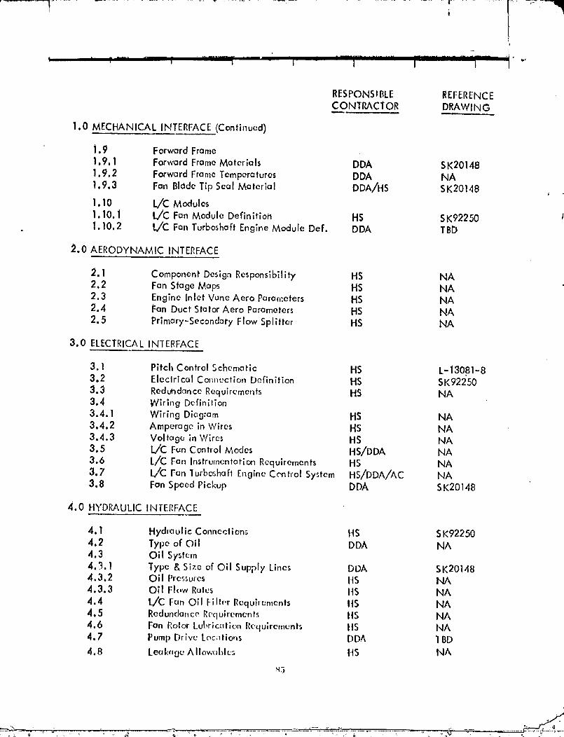
i
•" I
RESPONSIBLE REFERENCEC ONTP_CIOR DRAWING
1.0 MECHANICAL INTERFACE(Continued)
i .9 Forward Frame
1.9. ! Forward FrameMaterials DDA SK201481.9.2 Forward Frame Temperatures DDA NA
1.9.3 Fan Blade Tip Seal Material DDA/HS SK20148 ,1.10 L/C Modules
1.10. l L/C Fan Module Definitiotl HS SK92250 11.10.2 L/'C Fan Turboshaft Engine Module Def. DDA TBD
_.0 AERODYNAMIC INTERFACE
2. ! Component Design Responsibility HS NA2.2 Fan Stage Maps HS NA2.3 Engine Inlet Vane Aero Pc,rar,'.eters I'IS NA2.4 Fan Duct Stator Aero Parameters HS NA2.5 Primary-Seconda['y Flow Splitter HS NA
3.0 ELECTRICALINTERFACE
3.1 Pitch Control Schematic HS L-13081-83.2 Electrical Connection Definition HS SK922503.3 Reduhdance Requirements HS NA3.4 Wiring Definition
3.4.1 Wiring Diagram HS NA3.4.2 Amperage in Wires HS NA3.4.3 Voltage in Wires HS NA3.5 L,/C Fan Control Modes HS/DDA NA3.6 L/C Fan Instrumentation Requirements HS NA3.7 b/C Fan lurboshafl t'nglne Control System HS/DDA/AC NA3.8 Fan Speed Pickup DDA SK20148
4.0 trYDRAULIC INTERFACE
4.1 Hydraulic Connections HS SK922504.2 Type of Oil DDA NA4.3 Oil Syslem4.3.1 Type & Size of Oil Supply Lines DDA SK201484.3.2 Oil Pressures HS NA4.3.3 Oil Flow Rates It5 NA4.4 L/C Fan Oil Filler Requirements ItS NA4.5 Redundonce Requirements ItS NA4.6 Fan Rolor t ubrlcc,lion Rectulrements ItS NA4.7 Pump Drive Loc_,tio,ls DDA 1BD
4.8 Leeks,goA Ilow_d_h.'s HS NA
_3
"O000000i :TSG04

• " _'................................... II [ _ 6r]i "'" _'i '_ '_ I_''..............., ,- , ,-
A 6B_EVIATIONS:
TBD - To be determinedas the ptogranlprogresses.
NA - Not applicable, this notationapplies in thls table to the formoftransmittingdata. Themajority of the datasonotedwill besuppliedin the formof interface coordinationmemowhlchwillbecomea part of this interface document.
00000001-TSG05

I
ADDEN DUM A
LIFT FAN INTERFACE DEFINITION
N7/N,_
00000001-TSG06

I' t ! "11
I,. Ii
• |o,
ADDENDUM A
LIFT FAN INTERFACE DEFINITION
The lift fan interface whlch has been coordinated with the airframe study contractors_' Boeingand McDonnell, is pro,'ided by the inslallation drawlngs noted below. These
drawings will be updated during the fan detail design to define all mechanical ;r_ter-fa COS. '
Airframe Contractor Drowlt_ No.
Boeing $ K 92252McDonnell SK 92251
The bela regulator envelope as defined by drawing SK 92249 is common to bothairframe contrdctors and DDA fat the llft/cruise fan.
Addltional data pertaining to the lift fan interface which will b_ established during thefan detail design is as follows:
1.0 Fan Operatloncl Parameters
1.1 Fan Design Horsepower1.2 Fan Design Speed
2.0 Fan Characteristics
2. I Weight2.2 Polar Moment of Inertia
2.3 Center of Gravity2.4 Vibration Limits2.5 Guar Ratio
3.0 Aerodynamic Characterislics
3.1 Fan Stage Maps
4.0 Electrical Into'trace
4.1 Wi, lng Diagram4"2 Voltage Requirements4.3 rowcr Requhements4.4 Instrumer,k_lion R('qulrement_
x9
f_
00000001-TSG07

5.0 HydraullcInterf'aco
,S.1 PressureRequlremonts5.2 Flow Requffements5.3 F_llration Requirements5.4 Pitch Control Schematic5.5 Leakage Allowables5.6 Heat L_d
5.7 Type of Fluid
.qo
ONNNNNNI-TR_n_