Embed Size (px)
Citation preview

Code No. 0816490Rev. 1a (11/06)
INSTALLATION INSTRUCTIONS FOR ELECTRONICSENSOR ACTIVATED LAVATORY FAUCETS
LIMITED WARRANTYSloan Valve Company warrants its Optima EAF-275, EAF-250 and EAF-200 Series Electronic Hand Washing Faucets to be madeof first class materials, free from defects of material or workmanship under normal use and to perform the service for which theyare intended in a thoroughly reliable and efficient manner when properly installed and serviced, for a period of three years fromdate of purchase. During this period, Sloan Valve Company will, at its option, repair or replace any part or parts which prove tobe thus defective if returned to Sloan Valve Company, at customer’s cost, and this shall be the sole remedy available under thiswarranty. No claims will be allowed for labor, transportation or other incidental costs. This warranty extends only to persons ororganizations who purchase Sloan Valve Company’s products directly from Sloan Valve Company for purpose of resale. Thiswarranty does not cover the life of the battery.THERE ARE NO WARRANTIES WHICH EXTEND BEYOND THE DESCRIPTION ON THE FACE HEREOF. IN NO EVENT IS SLOAN VALVECOMPANY RESPONSIBLE FOR ANY CONSEQUENTIAL DAMAGES OF ANY MEASURE WHATSOEVER.
FAUCET ROUGH-IN
FAUCET VARIATIONS-ISM Integral Spout Mixer (All Series)-IC -Click Feature (EAF-200/250 Series)-DPU Drain Pop Up (EAF-200/250 Series)-P Plug-in Transformer (EAF-200 Series)-LT Less Transformer (EAF-200 Series)PRIOR TO INSTALLATIONPrior to installing the Sloan Optima EAF-275/EAF-250/EAF-200 Series Faucets, install the itemslisted below. Also, refer to rough-in illustrations.• Lavatory/sink• Drain line• Hot and cold water supply lines or pre-tempered
water supply lineImportant:• ALL PLUMBING SHOULD BE INSTALLED IN
ACCORDANCE WITH APPLICABLE CODES ANDREGULATIONS.
• FLUSH ALL WATER LINES PRIOR TO MAKINGCONNECTIONS.
• KEEP THREAD SEALANT OUT OF YOUR WATERWAYTO PREVENT COMPONENT PART DAMAGE! DO NOTUSE ANY SEALANT ON COMPRESSION FITTINGS.
Trim PlatesWhen the EAF Faucet is installed on a sink that hasthree (3) hole punchings, a Trim Plate should be used.Trim Plates must be specified and ordered separately.ETF-312-A Trim Plate for 4” (102 mm) Centerset SinkETF-510-A Trim Plate for 8” (203 mm) Centerset Sink
TOOLS REQUIRED FOR INSTALLATION• 13 mm open end wrench or nut driver for faucet
retainer nut• 3/4” open end wrench for female end of flex hose
SPOUT
TEMPEREDSUPPLY
O-RING
GASKET
RETAINER
NUT
1-3/16” (30 mm) MIN.DIA. HOLE REQUIRED
13” (330 mm) LONG FLEX HOSE
5-11/32”(136 mm)
24º
2-1/16”(52 mm) 2-9/16”
(65 mm)
2-1/16”(52 mm)
4-11/32”(110 mm)
MODELS EAF-200/250/275 ‡2.2 gpm (8.3 Lpm) Max. Flow Aerator ‡Faucets with Single Line Water Supply
EAF-250 SeriesBattery PoweredSensor ActivatedLavatory Faucets
EAF-200 SeriesTransformer PoweredSensor ActivatedLavatory Faucets(Models shown with ISM Integral Spout Mixer)
MODELS EAF-200/250/275-ISM ‡MODELS EAF-200/250-ISM-ICMODELS EAF-200/250-ISM-DPU-IC2.2 gpm (8.3 Lpm) Max. Flow Aerator ‡Faucets with Hot and Cold Water Supply
HOTSUPPLY
COLDSUPPLY
MIXING LEVER(Can Be Set and Removed)
1-1/2” (38 mm)MAX. DECKTHICKNESS
SPOUT
O-RING
1-3/16” (30 mm) MIN.DIA. HOLE REQUIRED
GASKET
RETAINER
NUT
13” (330 mm) LONG FLEX HOSE
1-1/2” (38 mm)MAX. DECKTHICKNESS
If a connection to separate hot and coldwater supplies is desired, then a Bak-Chek®
tee fitting (not supplied) must be used priorto connecting to the faucet.
EAF-275 SeriesSolar Poweredwith Battery BackupSensor ActivatedLavatory Faucets
FAUCET SPOUTDIMENSIONS
‡ EAF-275 Series Faucets are furnished with a 0.5 gpm (1.9 Lpm) Aerator Spray Head.
1 2Install Faucet. Slide Gasket over Flex Hose(s) andsecure with Faucet Retainer andNut.
A Remove Nut, FaucetRetainer and Gasket.
Do Not remove theO-ring from base ofFaucet.
Install Faucet with O-ringinto the center hole indeck or lavatory —1-3/16" (30 mm) min. holerequired.Note: If installing theFaucet on a three (3) holesink, a Trim Plate shouldbe installed at this time.
FAUCET
CENTER HOLE INDECK OR LAVATORY
GASKET
FAUCET RETAINER NUT
O-RING —DO NOT REMOVE
O-RING
B
NUT
FAUCET
FLEX HOSE
O-RING
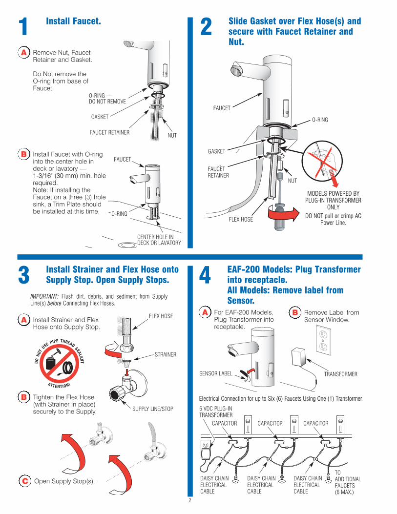
4 EAF-200 Models: Plug Transformerinto receptacle. All Models: Remove label fromSensor.
3 Install Strainer and Flex Hose ontoSupply Stop. Open Supply Stops.
A Install Strainer and FlexHose onto Supply Stop.
B Tighten the Flex Hose(with Strainer in place)securely to the Supply.
IMPORTANT: Flush dirt, debris, and sediment from SupplyLine(s) before Connecting Flex Hoses.
SUPPLY LINE/STOP
STRAINER
FLEX HOSE
TRANSFORMERSENSOR LABEL
C Open Supply Stop(s).
B Remove Label fromSensor Window.
2
A For EAF-200 Models,Plug Transformer intoreceptacle.
Electrical Connection for up to Six (6) Faucets Using One (1) Transformer
6 VDC PLUG-INTRANSFORMER
DAISY CHAINELECTRICALCABLE
DAISY CHAINELECTRICALCABLE
DAISY CHAINELECTRICALCABLE
TOADDITIONALFAUCETS (6 MAX.)
CAPACITOR CAPACITOR CAPACITOR
GASKET
FAUCETRETAINER
MODELS POWERED BYPLUG-IN TRANSFORMER
ONLYDO NOT pull or crimp AC
Power Line.
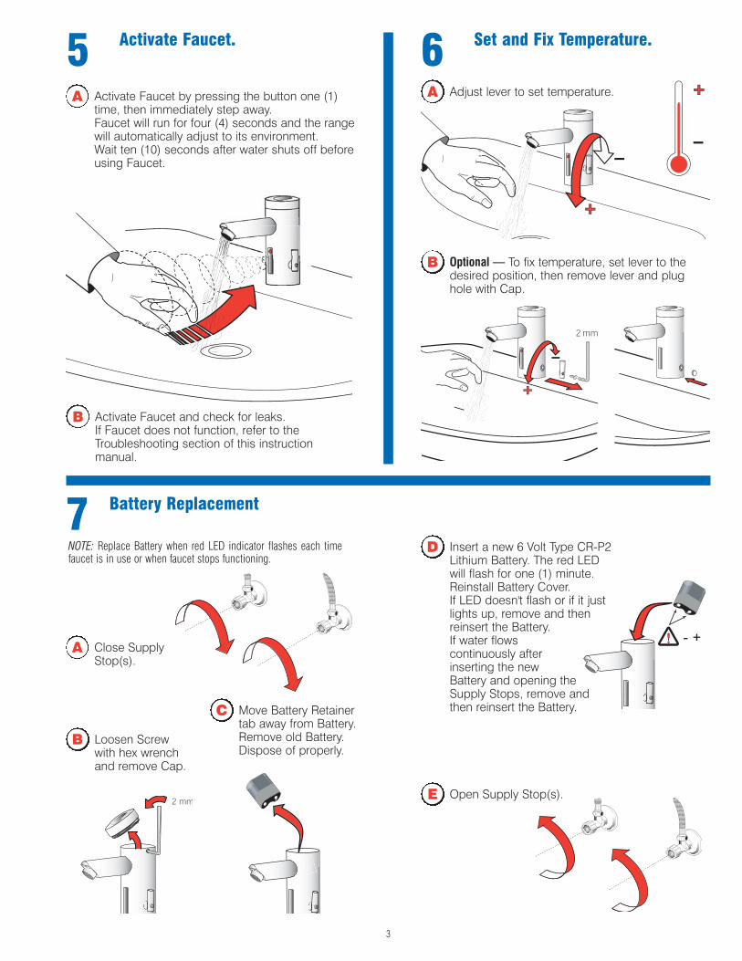
65 Activate Faucet. Set and Fix Temperature.
B Optional — To fix temperature, set lever to thedesired position, then remove lever and plughole with Cap.
B Activate Faucet and check for leaks.If Faucet does not function, refer to theTroubleshooting section of this instructionmanual.
A Activate Faucet by pressing the button one (1)time, then immediately step away.Faucet will run for four (4) seconds and the rangewill automatically adjust to its environment.Wait ten (10) seconds after water shuts off beforeusing Faucet.
A Adjust lever to set temperature.
7 Battery Replacement
B Loosen Screwwith hex wrenchand remove Cap.
A Close SupplyStop(s).
C Move Battery Retainertab away from Battery.Remove old Battery.Dispose of properly.
E Open Supply Stop(s).
NOTE: Replace Battery when red LED indicator flashes each timefaucet is in use or when faucet stops functioning.
3
D Insert a new 6 Volt Type CR-P2Lithium Battery. The red LEDwill flash for one (1) minute.Reinstall Battery Cover.If LED doesn't flash or if it justlights up, remove and thenreinsert the Battery.If water flows continuously after inserting the new Battery and opening theSupply Stops, remove andthen reinsert the Battery.

TROUBLESHOOTING GUIDE1. Problem: Faucet does not function.
Cause: Adhesive packaging label affixed over sensor eye.Solution: Remove adhesive label from sensor eye.Cause: "Permanent Off" activated.Solution: Press button on faucet throat one time.
2. Problem: Faucet delivers water in an uncontrolled manner.Cause: Faucet is defective.Solution: Contact the Sloan Valve Company Installation Engineering
Department (see below).
3. Problem: Faucet does not deliver any water when Sensor isactivated.
Indicator: Solenoid valve produces an audible “CLICK.”Cause: Water supply stop(s) closed.Solution: Open water supply stop(s).Cause: Water supply stop strainer(s) clogged.Solution: Remove, clean, and reinstall water supply stop
strainer(s).Replace strainer(s) if required.Indicator: Solenoid valve DOES NOT produce an audible “CLICK.”Cause: Battery low (battery operated models).Solution: Replace battery (refer to Battery Replacement on Page 3).Cause: Power failure (EAF-200 Models).Solution: Check power supply.
4. Problem: Faucet delivers only a slow flow or dribble when Sensoris activated.
Cause: Water supply stop(s) are partially closed.Solution: Completely open water supply stop(s).Cause: Water supply stop strainer(s) clogged.Solution: Remove, clean, and reinstall water supply stop
strainer(s).Replace strainer(s) if required.Cause: Aerator is clogged.Solution: Remove, clean, and reinstall Aerator. Replace Aerator if
required.Cause: Faucet is defective.Solution: Contact the Sloan Valve Company Installation Engineering
Department (see below).
5. Problem: Faucet does not stop delivering water or continues todrip after user is no longer detected.
Cause: Valve is defective.Solution: Contact the Sloan Valve Company Installation Engineering
Department (see below).
6. Problem: LED indicator blinks when faucet is in use.Cause: Battery low (battery operated models).Solution: Replace battery (refer to Battery Replacement on Page 3).
7. Problem: The water temperature is too hot or too cold on a faucetconnected to hot and cold supply lines.
Cause: Supply Stops are not adjusted properly.Solution: Adjust Supply Stops.Cause: For models with integral mixing valve — Mixing valve is set
improperly for the water temperature desired.Solution: Rotate mixing valve handle clockwise to decrease water
temperature or counterclockwise to increase water temperature.
PARTS LIST 2A2B
Item Part Description No. No.1 EAF-14-A Faucet Sensor Assembly2A EAF-1006 Cap and Solar Cell Assembly (EAF-275 only)2B EAF-27 Cap (EAF-250 and EAF-200 only)3A EAF-15 0.5 gpm (1.9 Lpm) VR Aerator Spray Head3B EAF-10 2.2 gpm (8.3 Lpm) Aerator Spray Head3C EAF-13 2.2 gpm (8.3 Lpm) Laminar Flow Spray Head4 EAF-1003 Battery Replacement Kit5 EAF-1 Faucet Mounting Kit6 EAF-9 Strainer (Filter)7A EAF-1004 Mixer Handle Assembly and Cartridge7B EAF-1005 Handle Repair Kit8 EAF-1007 Handle Cap9 EAF-1008 13” (330 mm) Flexible Supply Hose10 EAF-23-A Splitter Cable11 EAF-24-A 11-13/16” (300 mm) Extension Cable
EAF-25-A 47-1/4” (1200 mm) Extension CableEAF-17-A 126” (3200 mm) Extension Cable
12 ETF-312-A Trim Plate for 4” Centerset Sink13 ETF-510-A Trim Plate for 8” Centerset Sink14 EAF-11 Transformer15 EAF-28 Capacitor Box
3A3B3C
When assistance is required, please contact Sloan Valve Company InstallationEngineering Department at:
1-888-SLOAN-14 (1-888-756-2614) OR 1-847-233-2016
7A
7B
4
1
5
13
9 12
6
8
CARE AND CLEANING OF CHROME AND SPECIAL FINISHESDO NOT use abrasive or chemical cleaners (including chlorinebleach) to clean Faucets that may dull the luster and attack thechrome or special decorative finishes. Use ONLY mild soapand water, then wipe dry with clean cloth or towel.While cleaning the bathroom tile, protect the Faucet from anysplattering of cleaner. Acids and cleaning fluids will discoloror remove chrome plating.
OPERATIONAs the user’s hands enter the beam’s effectiverange, the beam is reflected back into the sensorreceiver and activates the solenoid valve allowingwater to flow from the faucet. Water will flow untilthe hands are removed or until the faucet reachesits automatic time out limit setting.
14
The information contained in this document is subject to change without notice.
-Click SETTINGS
Function Press Button LED Signal
Continuous Run — 2 minutedefault setting (adjustable from
1 - 20 minutes)1 time for 2 seconds 5 short flashes
reset: 1 time or will reset automatically after 2 minutes
Temporary Off 2 times (double click) 5 short flashes followed byperiodic flashing
reset: 1 time or will reset automatically after 2 minutes
Permanent Off Consult Factory Periodic flashing and then 2 long flashes
reset: 1 time
Auto Set Range Adjustment 2 times (double click) and then1 time for 5 seconds
5 short flashes followed by 4short flashes
SLOAN VALVE COMPANY • 10500 Seymour Avenue • Franklin Park, IL 60131Phone: 1-800-9-VALVE-9 or 1-847-671-4300 • Fax: 1-800-447-8329 or 1-847-671-4380
www.sloanvalve.com
Copyright © 2006 SLOAN VALVE COMPANY Printed 11-06
11
10
15