Embed Size (px)
Citation preview
erstellt am: 10.11.04 E4-WM4-Y553A00_2 Seite 1 von 20 geändert am: 08.09.08
Inhalt:
- Teile- Gutachten für: ( herausnehmbar)
- PEUGEOT 206 Limousine
- PEUGEOT 206 Coupe
- PEUGEOT 206 Break
- Einbauanleitungen
- englischer Anhang
Contents:
- certificate ( removable) for:
- PEUGEOT 206 sedan
- PEUGEOT 206 convertible
- PEUGEOT 206 station wagon
- mounting instruction
- english enclosure
erstellt am: 10.11.04 E4-WM4-Y553A00_2 Seite 2 von 20 geändert am: 08.09.08
Vor dem Umbau sind folgende Maßnahmen unbedingt durchzuführen:
Before installation please observe the following points:
- Lesen Sie die Hinweise auf den folgenden Seiten
aufmerksam durch. Alle Fahrwerkselemente werden gemäß den Vorgaben und Richtlinien der Fahrzeughersteller aus- und eingebaut, sofern in unserer Einbauanleitung keine davon abweichenden Maßnahmen beschrieben werden.
Read all information in this manual carefully. All suspention components are fitted and
removed acc. to the manufacturer’s specifications for fitting and removing, if not
otherwise required in these instructions.
-
- Kontrollieren Sie ob das vorliegende Kit/ Gutachten für Ihren Fahrzeugtyp richtig ausgewählt ist.
Check that your vehicle type is listed in the certificate as being released for this kit.
-
- Kontrollieren Sie vor Beginn der Umbauarbeiten das Produkt auf Vollständigkeit!
Check the product for all components before starting installation!
-
- Vergleichen Sie die Maße und Befestigungs-punkte/ -hilfen der Original- Stoßdämpfer mit den BILSTEIN – Stoßdämpfern.
Check that dimensions and fastening points are comparable between the original and Bilstein
shock absorbers.
-
- Richtungsangaben erfolgen immer in Fahrtrich-tung gesehen.
Directional references (left, right, front, rear) are always with reference to the driving direction.
-
- Die Prüffahrzeuge sind Linkslenker.
The test vehicles are left- hand drive cars. - Nach dem Umbau sind folgende Maßnahmen unbedingt durchzuführen:
After installation please observe the following points:
- Die Fahrzeughöhe muss mit Hilfe von Federteller
und Kontermutter auf die Stoßdämpfer abge-stimmt werden. Verwenden Sie nur die mitgelie-ferten Hakenschlüssel.
Set the vehicle height by adjusting spring plates and lock nuts on the new dampers. Only use the
supplied spanner wrenches.
-
- Spur, Sturz und, falls notwendig, die Bremskraft-regelung ( lastabhängig) und ABS- Sensoren sind gemäß Werksangaben zu kontrollieren und anschließend einzustellen.
After installing the suspension system, caster and camber must be checked and adjusted according to manufacturer’s specifications.
Check and reset load- dependent brake compensator and ABS system according
to manufacturer’s specifications.
-
- Die Scheinwerfereinstellung ist zu prüfen und bei Bedarf einzustellen.
Check and adjust headlight aim. -
- Die Freigängigkeit der Rad-/ Reifen- kombination ist zu überprüfen.
Because the vehicle has been lowered, freedom of movement for all wheel-/ tire- combinations must be checked.
-
- Federbeine/ Dämpfer die in Gummiaufhängun-gen gelagert sind, dürfen erst angezogen wer-den, wenn das Fahrzeug wieder auf dem Boden steht. Andere Befestigungen (z. B. Schellen) müssen vor dem Herablassen des Fahrzeugs angezogen werden.
All rubber- mounted strut/ damper attachments must not be fully tightened
until AFTER the suspension system is loaded (wheels on the ground). Other mounting
fasteners (for example brackets) must be securely tightened BEFORE load
is placed on the suspension system.
-
Darstellungen in diesen Unterlagen sind schema-tisch und nicht maßstabsgetreu! Möglicherweise sind Halter o. ä. am Federbein nicht oder nur angedeutet dargestellt!
All diagrams are generalized and not to scale!
Brackets, etc. specific to strut are not shown!

erstellt am: 10.11.04 E4-WM4-Y553A00_2 Seite 3 von 20 geändert am: 08.09.08
Einbauanleitung für Vorderachse - mounting instruction for front axle VE3-5239/ VE3-5240
Ausbau Das Fahrzeug auf eine radfreie Hebebühne stellen, anheben und Räder demontieren. Bei Fahrzeugen mit Xenon- Licht ist vor dem Ausbau der Federbeine, der Sensor für die Leuchtweitenregulierung auszubauen.
Die Schräglenker sind beim Ausbau stets mit geeignetem Hilfswerkzeug abzustützen!
Die untere Befestigung lösen und entfernen. Die obere Befestigungsmutter am Stützlager entfernen. Nicht die Kolbenstangen- Mutter lösen! Das Federbein komplett ausbauen und in einem geeigneten Spannbock spannen. Die Feder mit einem Spanngerät so weit vorspannen, bis das Stützlager frei ist. Mutter, Original- Anbauteile und Original- Feder demontieren. Hierbei ist zu prüfen, welche Original- Anbauteile durch Bilstein- Anbauteile ( Lieferumfang ) ersetzt werden.
Einbau BILSTEIN und/ oder Original- Anbauteile, sowie die neue BILSTEIN- Feder in umgekehrter Reihenfolge, ana-log zum Ausbau, auf BILSTEIN- Federbein montieren.
Der im Gutachten angegebene Verstell- bereich der Federteller darf nicht unter- oder überschritten werden!
Die Einbaulage der Federn ist an der Bedruckung ablesbar. Die Federbezeichnung muss in Einbaulage lesbar sein. Das komplettierte BILSTEIN- Federbein in umgekehrter Reihenfolge analog zum Ausbau wieder montieren. Federbeine/ Dämpfer die in Gummiaufhängungen gelagert sind, dürfen erst angezogen werden, wenn das Fahrzeug wieder auf dem Boden steht. Andere Befestigungen (z. B. Schellen) müssen vor dem Herablassen des Fahrzeugs angezogen werden. Achten Sie dabei auf eine korrekte Befestigung der Gummipuffer sowie des Schutzrohres.
Removal
Place vehicle on a chassis hoist, lift it and remove wheels.
Vehicles equipped with xenon
headlight the sensor for the headlamp levelling controller must removed before.
The lower control arm must be supported by suitable means!
Remove bottom mount.
Remove top fixing nut from support bearing. Do not remove centre nut at this time!
Remove complete strut and
clamp it in an appropriate strut vice.
Using a suitable spring compressor, compress suspen-sion spring until tension on support bearing is released.
Release centre nut and remove original
mounting parts and coil spring. Please refer to diagram to identify which parts will be re-
placed with BILSTEIN- supplied components.
Install
Assemble BILSTEIN and/ or original mounting parts, as well as the new BILSTEIN spring on the
BILSTEIN strut in reverse sequence of removal.
IMPORTANT! Spring plates must not be adjusted outside the
ranges specified below!
The correct mounting position of the suspension springs can be determined by the printing on
the springs; install them with the print upright.
Fit assembled BILSTEIN strut to the vehicle in reverse sequence to removal.
All rubber- mounted strut/ damper attachments must not
be fully tightened until AFTER the suspension system is loaded (wheels on the ground). Other
mounting fasteners (for example brackets) must be securely tightened BEFORE load is placed on the
suspension system. Make sure that the bump stop and dust cover are correctly and properly fastened.
erstellt am: 10.11.04 E4-WM4-Y553A00_2 Seite 4 von 20 geändert am: 08.09.08
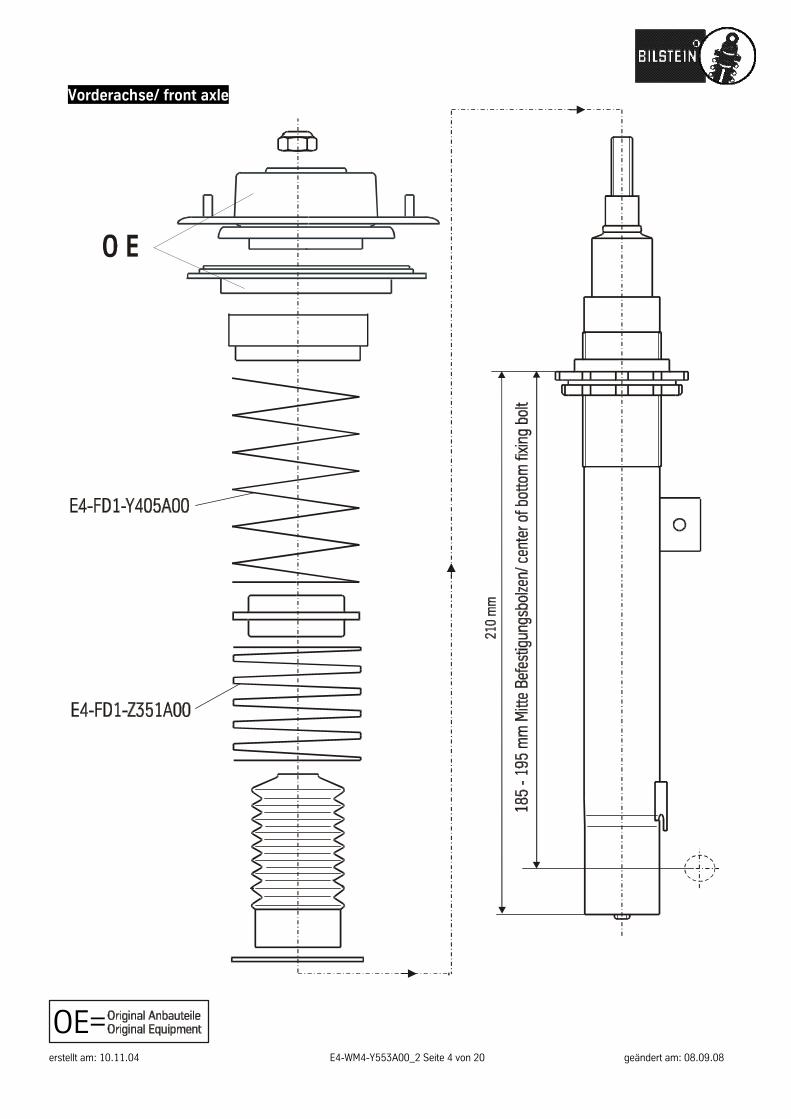
Vorderachse/ front axle
OE=

erstellt am: 10.11.04 E4-WM4-Y553A00_2 Seite 5 von 20 geändert am: 08.09.08
- Teile- Gutachten für: ( herausnehmbar)
- PEUGEOT 206 Limousine
- PEUGEOT 206 Coupe
- PEUGEOT 206 Break
Contents:
- certificate ( removable) for:
- PEUGEOT 206 sedan
- PEUGEOT 206 convertible
- PEUGEOT 206 station wagon

erstellt am: 10.11.04 E4-WM4-Y553A00_2 Seite 6 von 20 geändert am: 08.09.08

erstellt am: 10.11.04 E4-WM4-Y553A00_2 Seite 7 von 20 geändert am: 08.09.08

erstellt am: 10.11.04 E4-WM4-Y553A00_2 Seite 8 von 20 geändert am: 08.09.08

erstellt am: 10.11.04 E4-WM4-Y553A00_2 Seite 9 von 20 geändert am: 08.09.08

erstellt am: 10.11.04 E4-WM4-Y553A00_2 Seite 10 von 20 geändert am: 08.09.08

erstellt am: 10.11.04 E4-WM4-Y553A00_2 Seite 11 von 20 geändert am: 08.09.08
erstellt am: 10.11.04 E4-WM4-Y553A00_2 Seite 12 von 20 geändert am: 08.09.08

erstellt am: 10.11.04 E4-WM4-Y553A00_2 Seite 13 von 20 geändert am: 08.09.08

erstellt am: 10.11.04 E4-WM4-Y553A00_2 Seite 14 von 20 geändert am: 08.09.08

erstellt am: 10.11.04 E4-WM4-Y553A00_2 Seite 15 von 20 geändert am: 08.09.08

erstellt am: 10.11.04 E4-WM4-Y553A00_2 Seite 16 von 20 geändert am: 08.09.08

erstellt am: 10.11.04 E4-WM4-Y553A00_2 Seite 17 von 20 geändert am: 08.09.08
Anhang englisch - english enclosure The adjustment range of the spring plates is only approved within the range of the values given in Point I. Adjustment must be carried out so that the body is level when the vehicle is empty apart from the driver. The lowest approved adjustment and the permissible adjustment range are to be entered, stating the fixed axle reference points. (Example, see below).
Manufacturer PEUGEOT
ABE-/ EG- BE- No. type designation
e2*93/81*0085*.. e2*98/14*0085*.. e2*93/81*0168*.. e2*98/14*0168*.. e2*93/81*0169*.. e2*93/81*0170*.. e2*93/81*0171*.. e2*98/14*0171*.. e2*93/81*0172*.. e2*93/81*0173*.. e2*98/14*0173*.. e2*93/81*0174*.. e2*98/14*0174*.. e2*93/81*0212*.. e2*98/14*0212*.. e2*98/14*0237*.. e2*98/14*0238*.. e2*98/14*0239*.. e2*98/14*0250*.. e2*2001/116*0269*.. e2*2001/116*0291*.. e2*2001/116*0310*.. e2*2001/116*0311*..
2-WJY 2-HFZ 2-HFY 2-KFX 2-NFZ 2-RFR 2-WJZ 2-RHY 2-HFX 2-KFW 2-NFU 2-RFN 2-8HX 2-RFK 2-KFU 2-9HZ 2-8HZ
model 206
I. FRONT maximum permissible axle load 890 kg= 1958 lb
spring part number main spring E4-FD1-Y405A00
helper spring E4-FD1-Z351A00
shock absorber part number
VE3-5239 left/ VE3-5240 right
without damping force adjustment
permissible adjustment range
185 – 195 mm*= 10 mm range
* measurement: top edge of spring seat down to centre of bottom fixing bolt

erstellt am: 10.11.04 E4-WM4-Y553A00_2 Seite 18 von 20 geändert am: 08.09.08
rear maximum permissible axle load 780 kg= 1716 lb
spring part number o.e. torsion-bar spring height matching by adjustment of toothing (1 tooth)
shock absorber part number
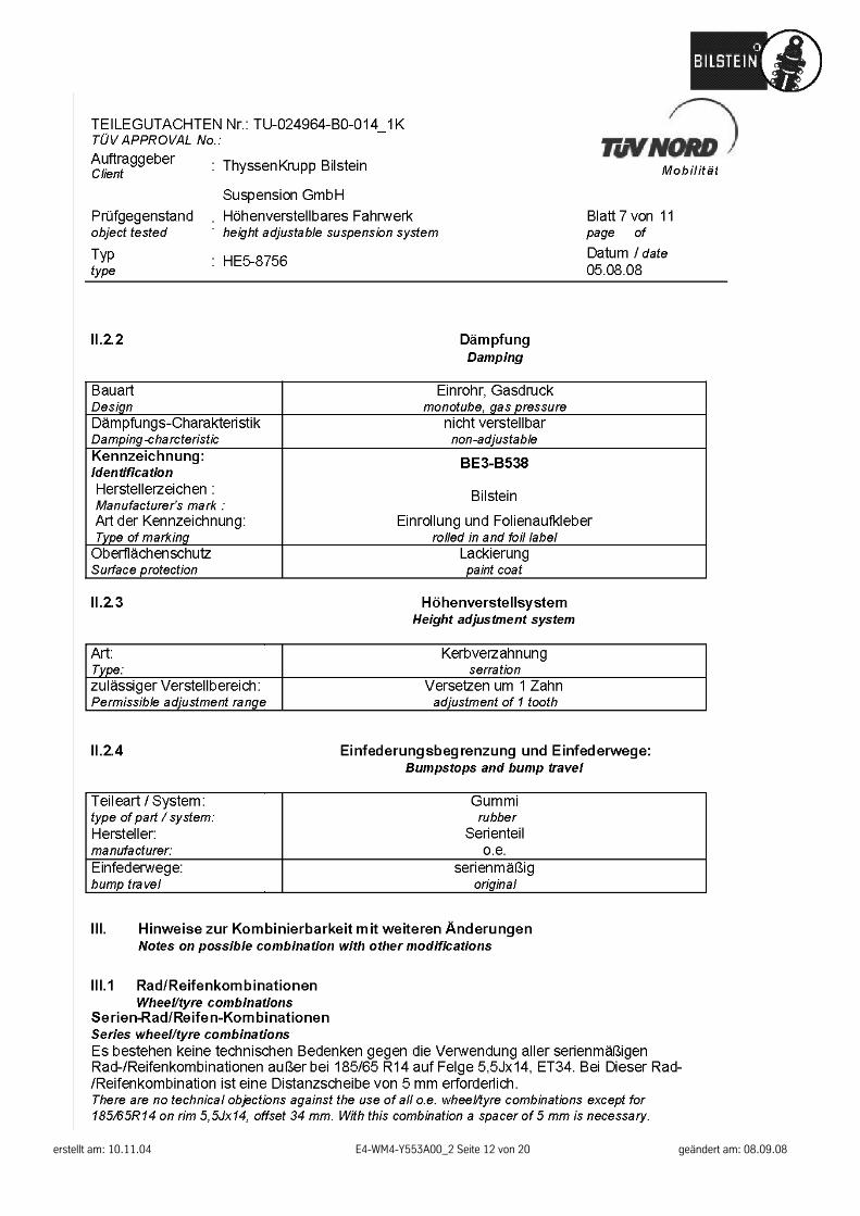
BE3-B538 without damping force
adjustment
There are no technical objections against the use of all o.e. wheel/tyre combinations except for 185/65R14 on rim 5,5Jx14, offset 34 mm. With this combination a spacer of 5 mm is necessary.
Because of the increased bump travel on axle 1, all special wheel/tyre combinations which have already been entered ( approved) must be re-examined with regard to freedom of motion. Critical areas are f.e. area of inner and outer tyre flank above centre of wheel.
In so far as these wheel-/ tyre combinations are not listed below, the examination must by carried out by an officially recognised expert or test engineer at a TÜV/TÜH test facility. The vehicle registration document in ac-cordance with §21 German Road Traffic Licensing Code - StVZO must be presented. Any certificates already obtained with regard to special wheel/tyre combinations are invalid if they do not contain a reference to the suspension system described in this document.
The dynamic ground clearance is decreased by the provision of special springs/dampers which increase the bump travel of the front and rear axle. In the case of the test vehicle, the distance from the ground amounted to 100 mm under the motor crossbar. Care must be taken when driving over humps, barriers and heightened paving or road surfaces. If special spoilers, aprons and exhaust systems are mounted, attention must be paid to the decreased overhang angle (driving up ramps etc.).
The specified minimum height of the coupling ball above the road surface with the permissible total weight of the vehicle (acc. DIN 74058) is 350 mm.

erstellt am: 10.11.04 E4-WM4-Y553A00_2 Seite 19 von 20 geändert am: 08.09.08
Einbauanleitung für Hinterachsen - mounting instuction for rear axle BE3-B538
Ausbau Fahrzeug auf eine radfreie Hebebühne stellen, anheben und Räder demontieren.
Die Schräglenker sind beim Ausbau stets mit geeignetem Hilfswerkzeug abzustützen!
Untere und obere Befestigung am Stützlager entfernen. Anschließend den Stoßdämpfer ausbauen und die Original Anbauteile demontieren. Einbau Original-/ BILSTEIN Anbauteile in umgekehrter Reihenfolge, analog zum Ausbau, montieren. BILSTEIN- Stoßdämpfer in umgekehrter Reihenfolge, analog zum Ausbau, montieren. Verstellung der Drehstabfeder nach Werkstattvorgabe, um einen Zahn verstellen.
Vor dem Ausbau der Drehstäbe sind diese in Ihrer jetzigen Lage durch Körnerschläge auf beiden Seiten zu markieren. Um die Ver-zahnung der Drehstäbe zu verstellen, müs-sen die unteren Befestigungsschrauben des Stossdämpfers ausgebaut werden. Ferner ist, soweit vorhanden, das Gestänge vom Bremskraftregler auszuhängen.
Removal
Place vehicle on a chassis hoist, lift it and remove wheels.
The lower control arm must be supported by suitable means!
Remove top and bottom fixing mount.
Remove shock absorber and
original mounting parts.
Install
Assemble BILSTEIN and/ or original mounting parts on BILSTEIN shock
absorber in reverse sequence of removal.
Fit BILSTEIN shock absorber to the vehicle in reverse sequence of removal.
Before remove torsion springs the
present position must be marked by punch on both sides. The bottom mount
of shock absorber must be removed before the serration of torsion spring
can be adjusted. If the vehicle is equipped with brake- power controller,
the bars must be detached.

erstellt am: 10.11.04 E4-WM4-Y553A00_2 Seite 20 von 20 geändert am: 08.09.08
erstellt am: 10.11.04 E4-WM4-Y553A00_2 Seite 20 von 20 geändert am: 08.09.08