Embed Size (px)
Citation preview
2
AGENDA設備外觀介紹基礎操作介面介紹運作原理說明無線網路基本設定Mesh 設定AP 設定除錯及查看訊息Q&A
3
設備外觀介紹
4
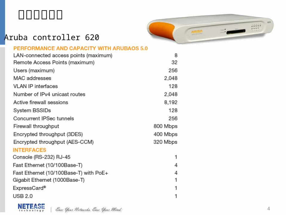
機器外觀介紹Aruba controller 620
5
機器外觀介紹
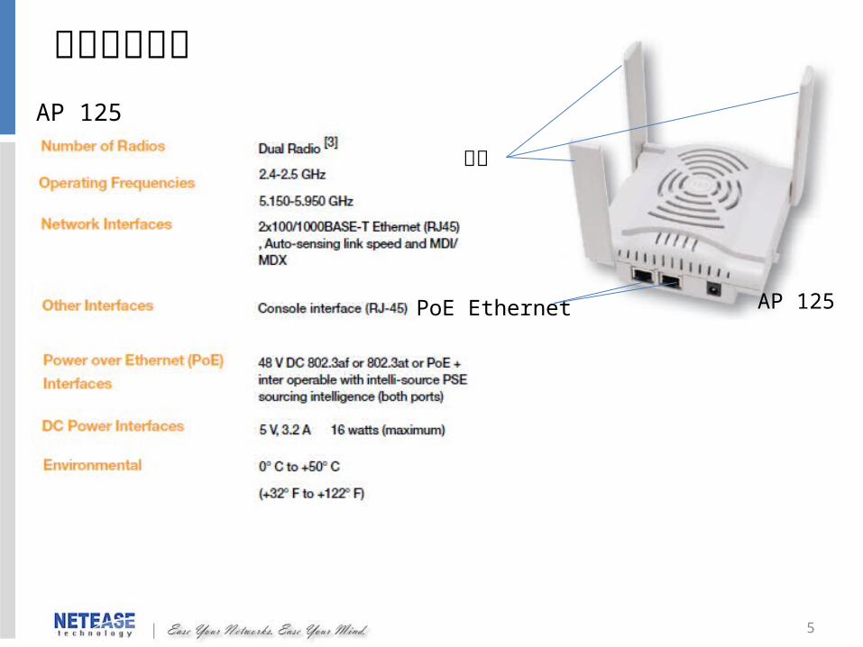
AP 125
天線
PoE Ethernet
AP 125
6
基礎操作介面介紹
7
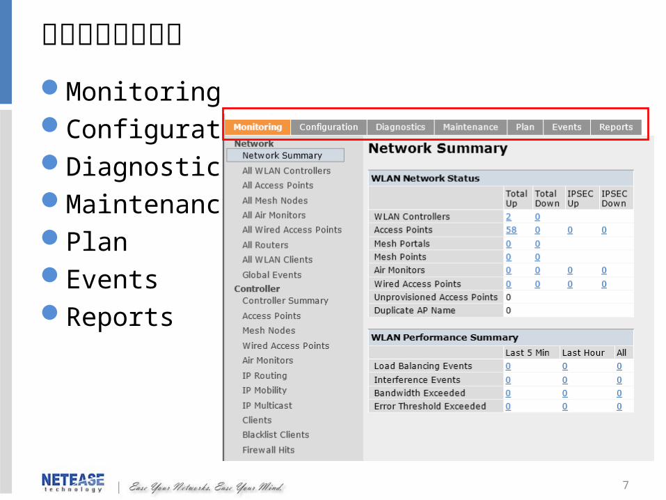
基礎操作介面介紹MonitoringConfigurationDiagnosticsMaintenancePlanEventsReports
8
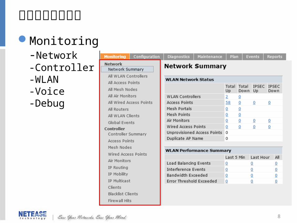
基礎操作介面介紹Monitoring
-Network-Controller-WLAN-Voice-Debug

9
基礎操作介面介紹
Configuration-Wizards-Network-Security-Wireless-Management-Advanced Services

10
基礎操作介面介紹
Diagnostics-Network-General-Access Point
11
基礎操作介面介紹
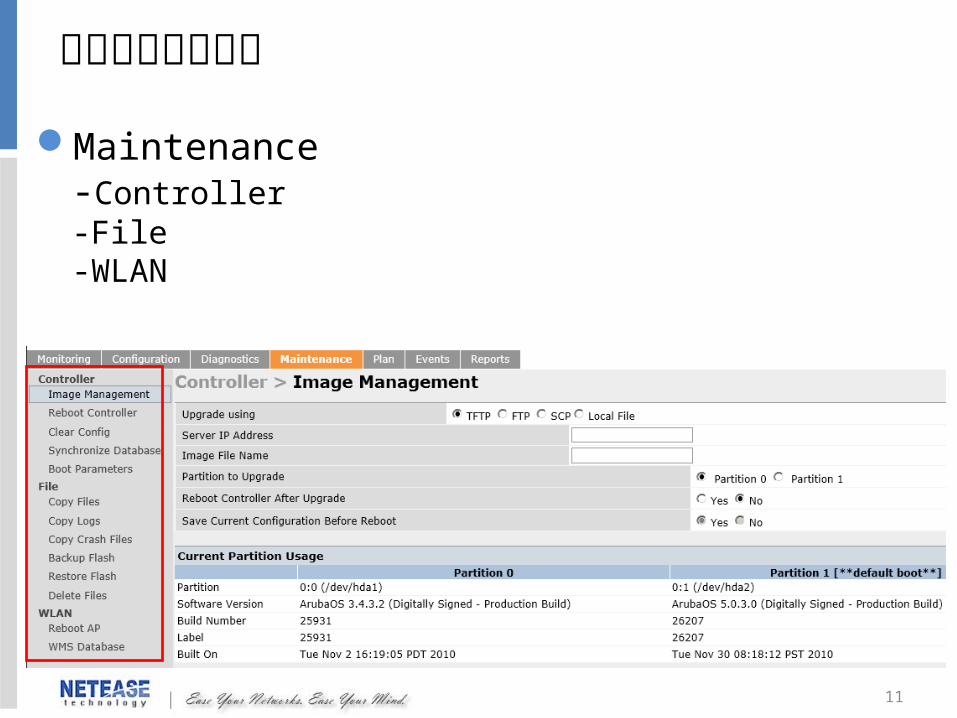
Maintenance-Controller-File-WLAN

12
運作原理說明
13
L2 Deployment
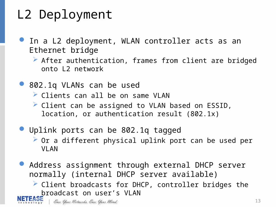
In a L2 deployment, WLAN controller acts as an Ethernet bridge After authentication, frames from client are bridged onto L2 network
802.1q VLANs can be used Clients can all be on same VLAN Client can be assigned to VLAN based on ESSID, location, or
authentication result (802.1x)
Uplink ports can be 802.1q tagged Or a different physical uplink port can be used per VLAN
Address assignment through external DHCP server normally (internal DHCP server available) Client broadcasts for DHCP, controller bridges the broadcast on user’s
VLAN

14
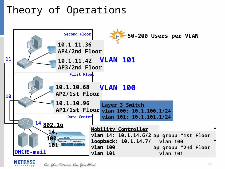
Theory of Operations
Data Center
First Floor
Second Floor
DHCPE-mail
10
11
14
10.1.10.96AP1/1st Floor
10.1.10.68AP2/1st Floor
10.1.11.42AP3/2nd Floor
10.1.11.36AP4/2nd Floor
VLAN 14: 10.1.14.6/24loopback: 10.1.14.7/32
VLAN 14
15
Data Center
First Floor
Second Floor
DHCPE-mail
10
11
14
10.1.10.96AP1/1st Floor
10.1.10.68AP2/1st Floor
10.1.11.42AP3/2nd Floor
10.1.11.36AP4/2nd Floor
Mobility Controllervlan 14: 10.1.14.6/24loopback: 10.1.14.7/32vlan 100vlan 101
150-200 Users per VLAN
VLAN 101
VLAN 100
Layer 3 Switchvlan 100: 10.1.100.1/24vlan 101: 10.1.101.1/24
ap group “1st Floor”vlan 100
ap group “2nd Floor”vlan 101
802.1q14, 100,
101
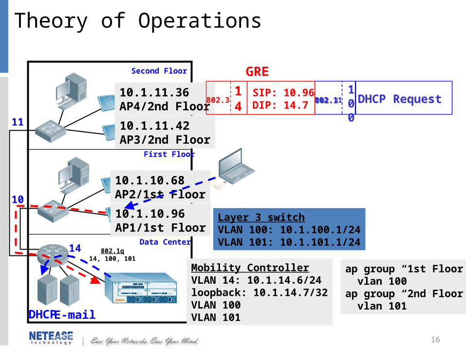
Theory of Operations
16
Data Center
First Floor
Second Floor
DHCPE-mail
10
11
14
10.1.10.96AP1/1st Floor
10.1.10.68AP2/1st Floor
10.1.11.42AP3/2nd Floor
10.1.11.36AP4/2nd Floor
Mobility ControllerVLAN 14: 10.1.14.6/24loopback: 10.1.14.7/32VLAN 100VLAN 101
Layer 3 switchVLAN 100: 10.1.100.1/24VLAN 101: 10.1.101.1/24
DHCP Request802.1114
100
SIP: 10.96DIP: 14.7802.3
GRE
802.1q14, 100, 101
ap group “1st Floor”vlan 100
ap group “2nd Floor”vlan 101
802.3
Theory of Operations

17
Data Center
First Floor
Second Floor
DHCPE-mail
10
11
14
10.1.10.96AP1/1st Floor
10.1.10.68AP2/1st Floor
10.1.11.42AP3/2nd Floor
10.1.11.36AP4/2nd Floor
Mobility ControllerVLAN 14: 10.1.14.6/24loopback: 10.1.14.7/32VLAN 100VLAN 101
Layer 3 switchVLAN 100: 10.1.100.1/24VLAN 101: 10.1.101.1/24
DHCP Reply10.1.100.32
SIP: 14.7DIP: 10.96 802.11802.3
14
100
GRE
802.1q14, 100, 101
10.1.100.32
ap group “1st Floor”vlan 100
ap group “2nd Floor”vlan 101
802.3
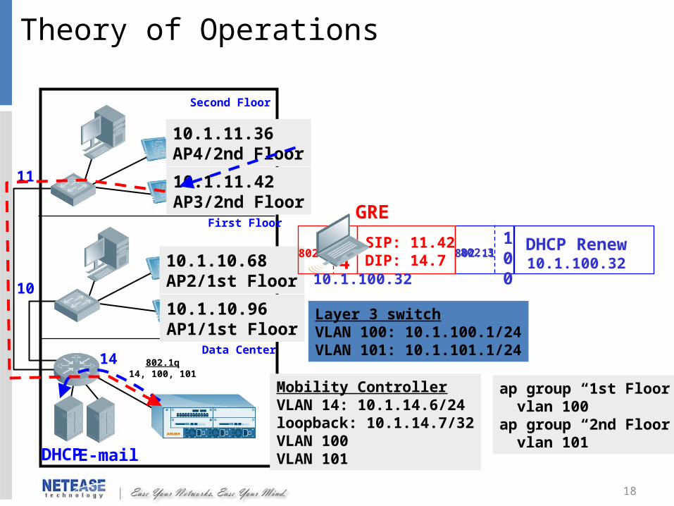
Theory of Operations
18
Theory of Operations
Data Center
First Floor
Second Floor
DHCPE-mail
10
11
14
10.1.10.96AP1/1st Floor
10.1.10.68AP2/1st Floor
10.1.11.42AP3/2nd Floor
10.1.11.36AP4/2nd Floor
Mobility ControllerVLAN 14: 10.1.14.6/24loopback: 10.1.14.7/32VLAN 100VLAN 101
Layer 3 switchVLAN 100: 10.1.100.1/24VLAN 101: 10.1.101.1/24
DHCP Renew10.1.100.32
802.1114
100
SIP: 11.42DIP: 14.7802.3
GRE
802.1q14, 100, 101
10.1.100.32
ap group “1st Floor”vlan 100
ap group “2nd Floor”vlan 101
802.3

19
Data Center
First Floor
Second Floor
DHCPE-mail
10
11
14
10.1.10.96AP1/1st Floor
10.1.10.68AP2/1st Floor
10.1.11.42AP3/2nd Floor
10.1.11.36AP4/2nd Floor
Mobility ControllerVLAN 14: 10.1.14.6/24loopback: 10.1.14.7/32VLAN 100VLAN 101
Layer 3 switchVLAN 100: 10.1.100.1/24VLAN 101: 10.1.101.1/24
DHCP Reply10.1.100.32
SIP: 14.7DIP: 11.42
802.11802.314
100
GRE
802.1q14, 100, 101
10.1.100.32
ap group “1st Floor”vlan 100
ap group “2nd Floor”vlan 101
802.3
Theory of Operations

20
無線網路基本設定
21
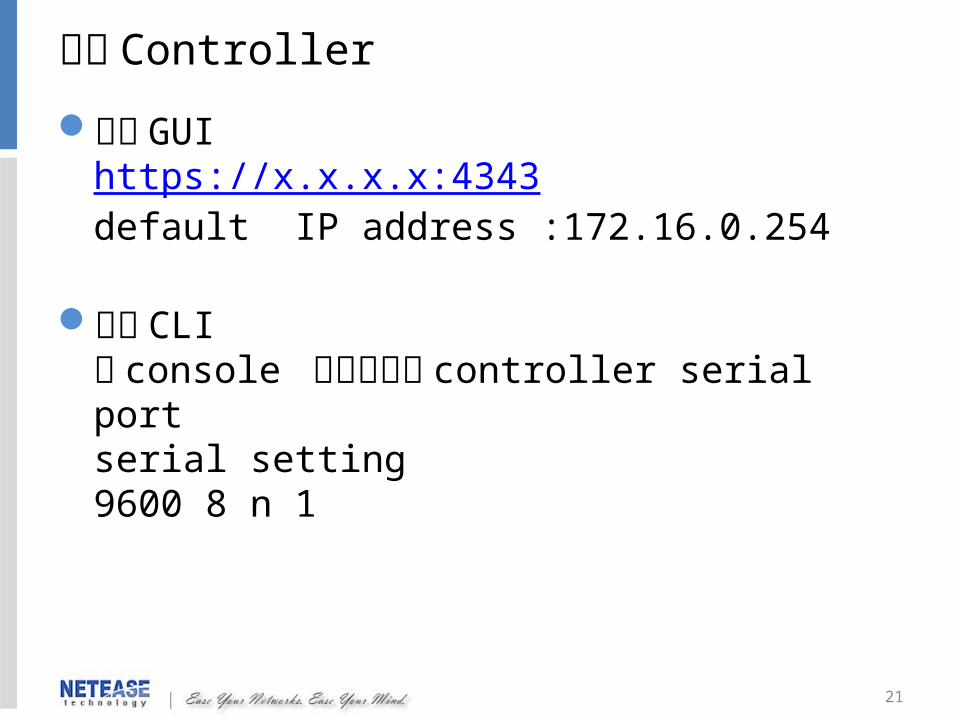
登入 Controller
使用 GUIhttps://x.x.x.x:4343default IP address :172.16.0.254
使用 CLI將 console 控制線接至 controller serial portserial setting9600 8 n 1
22
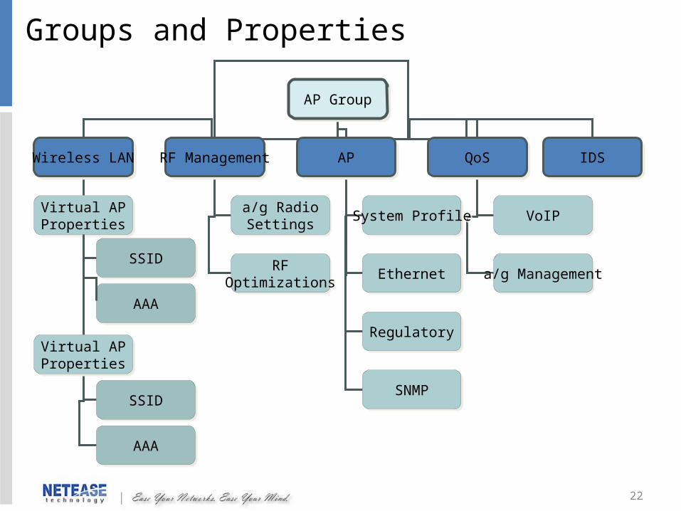
AP GroupAP Group
Wireless LANWireless LAN RF ManagementRF Management APAP QoSQoS IDSIDS
Virtual APProperties
Virtual APProperties
SSIDSSID
AAAAAA
a/g RadioSettings
a/g RadioSettings
RFOptimizations
RFOptimizations
System ProfileSystem Profile
EthernetEthernet
RegulatoryRegulatory
SNMPSNMP
VoIPVoIP
a/g Managementa/g Management
Virtual APProperties
Virtual APProperties
SSIDSSID
AAAAAA
Groups and Properties
23
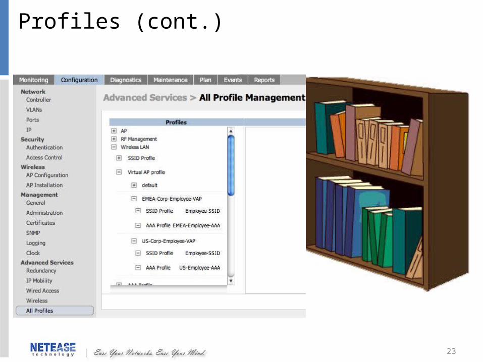
Profiles (cont.)

24
設定範例在實驗室中,為了安全考量, SSID 分類為
student : WPA2-PSKGuest : web authentication ,不能存取 student vlan
Vlan 分配:student : Vlan 1 IP 192.168.1.0/24Guest : Vlan 11 IP 192.168.11.0/24
25
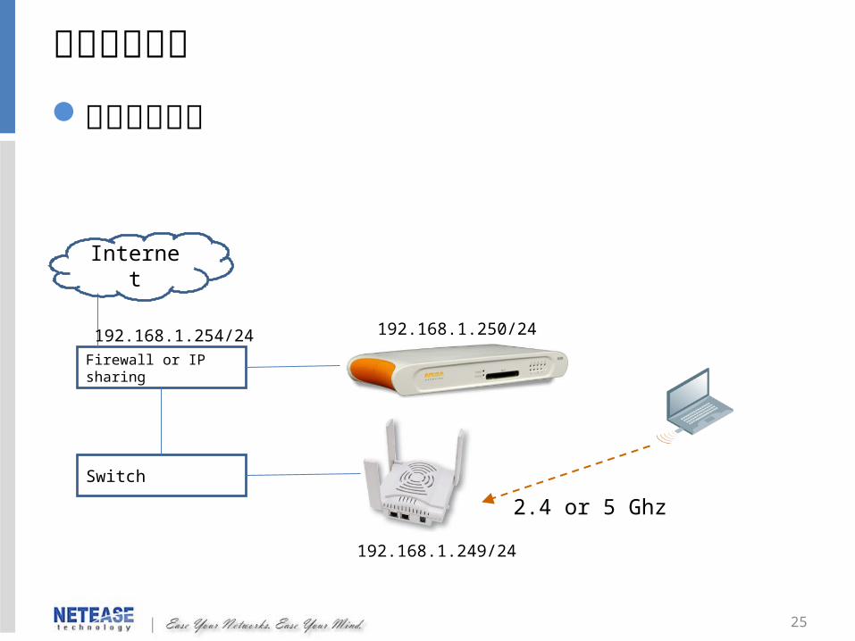
範例架構說明無線存取架構
Firewall or IP sharing
Switch
Internet
2.4 or 5 Ghz
192.168.1.250/24192.168.1.254/24
192.168.1.249/24

26
設定步驟新增 student and Guest Vlan 、 IP 、 DHCP新增 student 及 Guest SSID設定 student 屬性、 role設定 Guest firewall policy 、 role新增 student 及 Guest aaa profile新增 student 及 Guest Virtual AP profile新增 Group新增 AP

27
Network->Vlan->add新增 Guest vlan 11 ,選擇 2-3 為 access portApply
新增 student and Guest Vlan
28
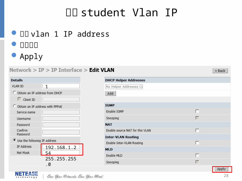
設定 vlan 1 IP address下圖紅框Apply
設定 student Vlan IP
1
192.168.1.254255.255.255.0
29
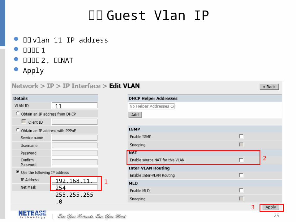
設定 vlan 11 IP address 下圖紅框 1 下圖紅框 2 ,啟用 NAT Apply
設定 Guest Vlan IP
11
192.168.11.254255.255.255.0
1
2
3
30
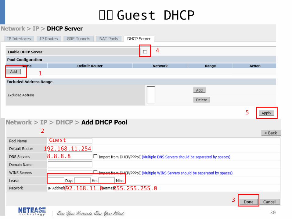
新增 Guest DHCP
Guest
192.168.11.2548.8.8.8
192.168.11.0 255.255.255.0
1
2
4
5
3
31
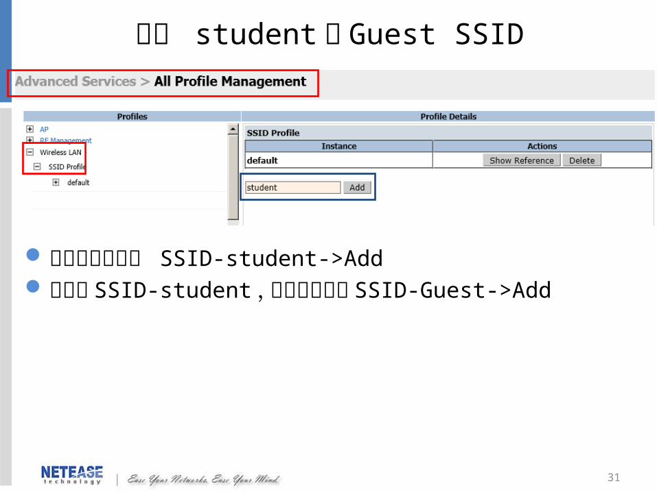
新增 student 及 Guest SSID
先在藍框處輸入 SSID-student->Add新增完 SSID-student ,在藍框處輸入 SSID-Guest->Add
32
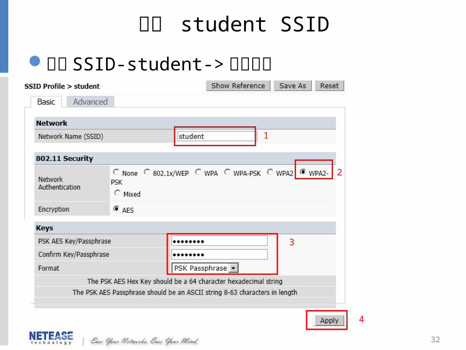
編輯 student SSID
點選 SSID-student-> 編輯內容
1
2
3
4
33
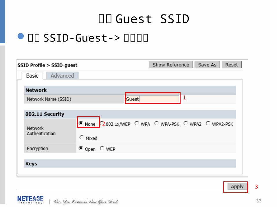
點選 SSID-Guest-> 編輯內容編輯 Guest SSID
1
2
3

34
設定 Guest firewall policy
新增阻斷存取 192.168.1.0/24 ACL新增上網連線 ACL
1
2
3
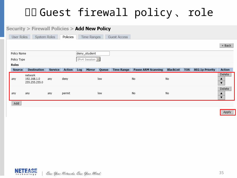
35
設定 Guest firewall policy 、 role
36
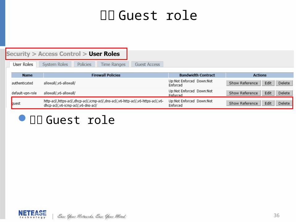
編輯 Guest role
編輯 Guest role
37
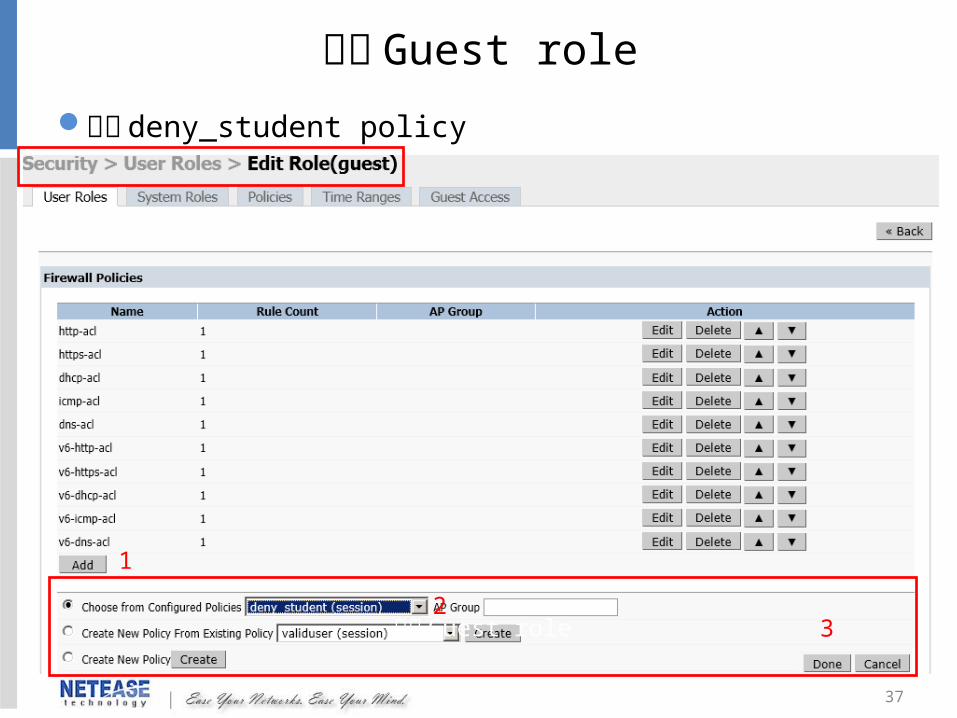
編輯 Guest role
新增 deny_student policy
編輯 Guest role
1
23

38
編輯 Guest role
設定 Captive portal profile :default
4
5
39
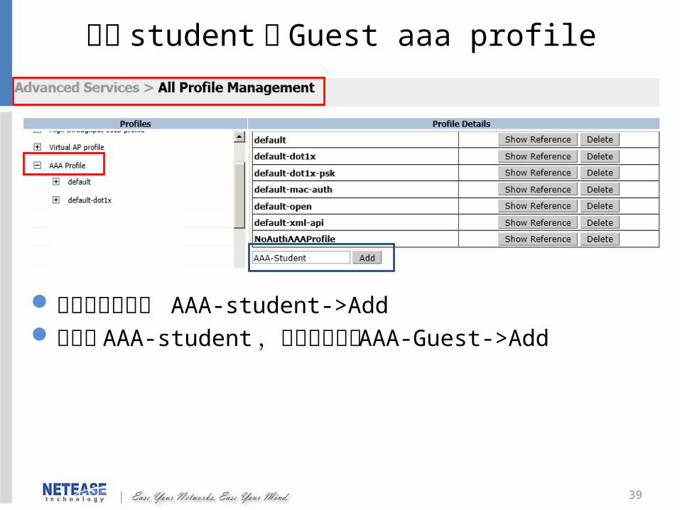
新增 student 及 Guest aaa profile
先在藍框處輸入 AAA-student->Add新增完 AAA-student ,在藍框處輸入 AAA-Guest->Add

40
編輯 student aaa profile 點選 AAA-Student-> 編輯內容 將 authenticated role 套用至 AAA-Student profile , 802.1x
authentication default role
1
2
3
41
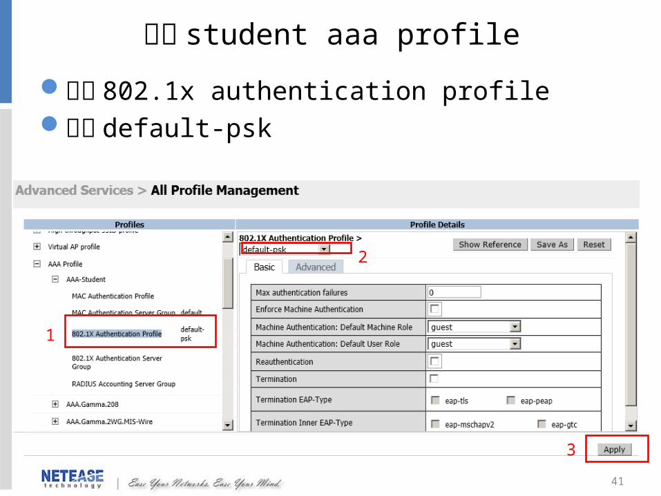
編輯 student aaa profile
設定 802.1x authentication profile選擇 default-psk
1
2
3

42
編輯 Guest aaa profile
點選 AAA-Guest-> 編輯內容將 guest role 套用至 AAA-Guest profile Intial role
1
2
3

43
新增 student 及 Guest Virtual AP profile
先在藍框處輸入 VAP-student->Add新增完 VAP-student ,在藍框處輸入 VAP-Guest->Add
44
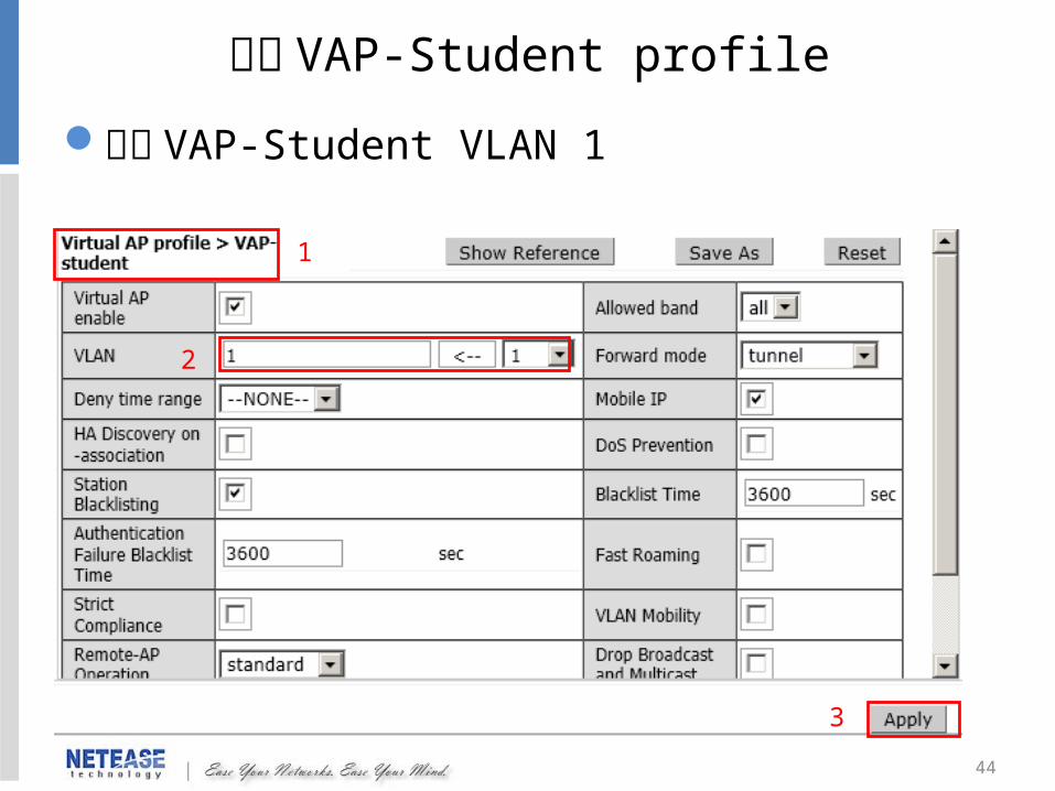
編輯 VAP-Student profile
新增 VAP-Student VLAN 1
1
2
3
45
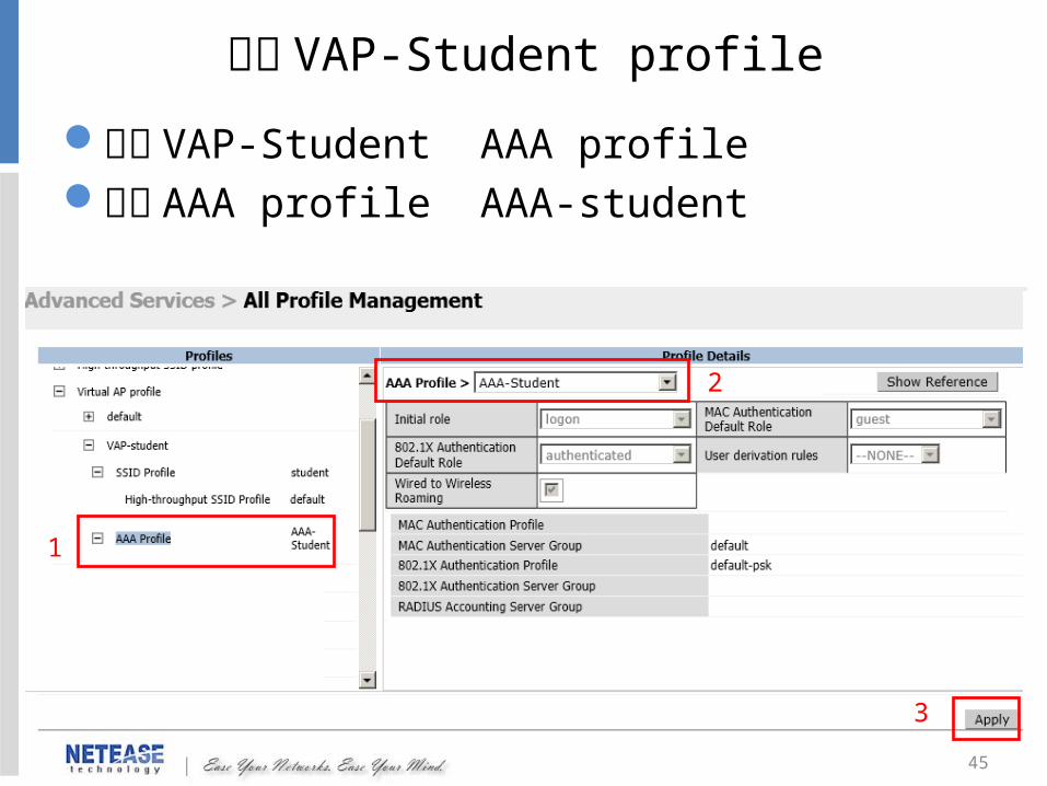
設定 VAP-Student AAA profile選擇 AAA profile AAA-student
編輯 VAP-Student profile
1
2
3

46
設定 VAP-Student SSID profile選擇 SSID profile SSID-student
編輯 VAP-Student profile
1
2
3

47
新增 VAP-Guest VLAN 11
編輯 VAP-Guest profile
1
2
3
48
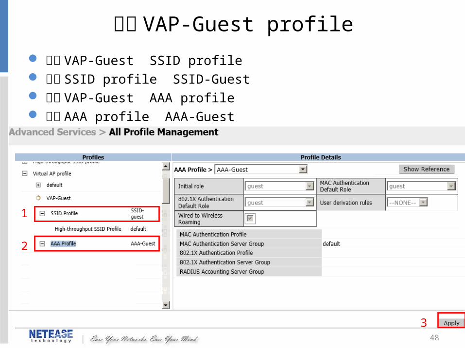
設定 VAP-Guest SSID profile 選擇 SSID profile SSID-Guest 設定 VAP-Guest AAA profile 選擇 AAA profile AAA-Guest
編輯 VAP-Guest profile
1
2
3
49
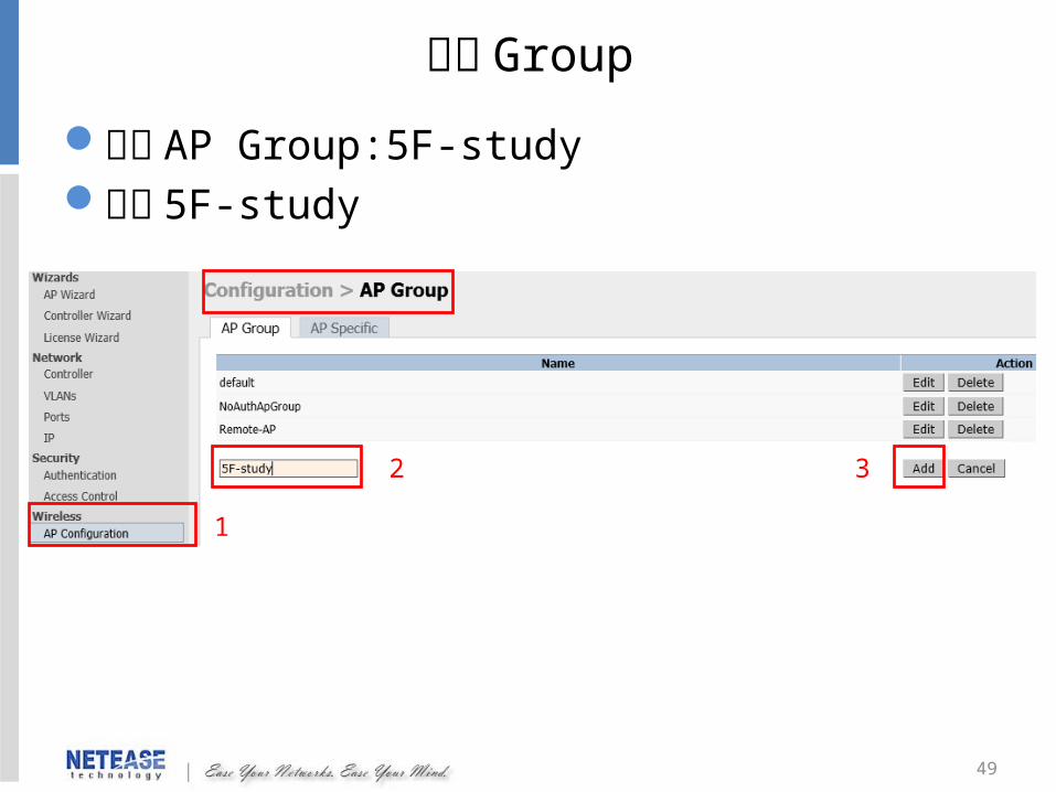
新增 Group
新增 AP Group:5F-study編輯 5F-study
1
32
50
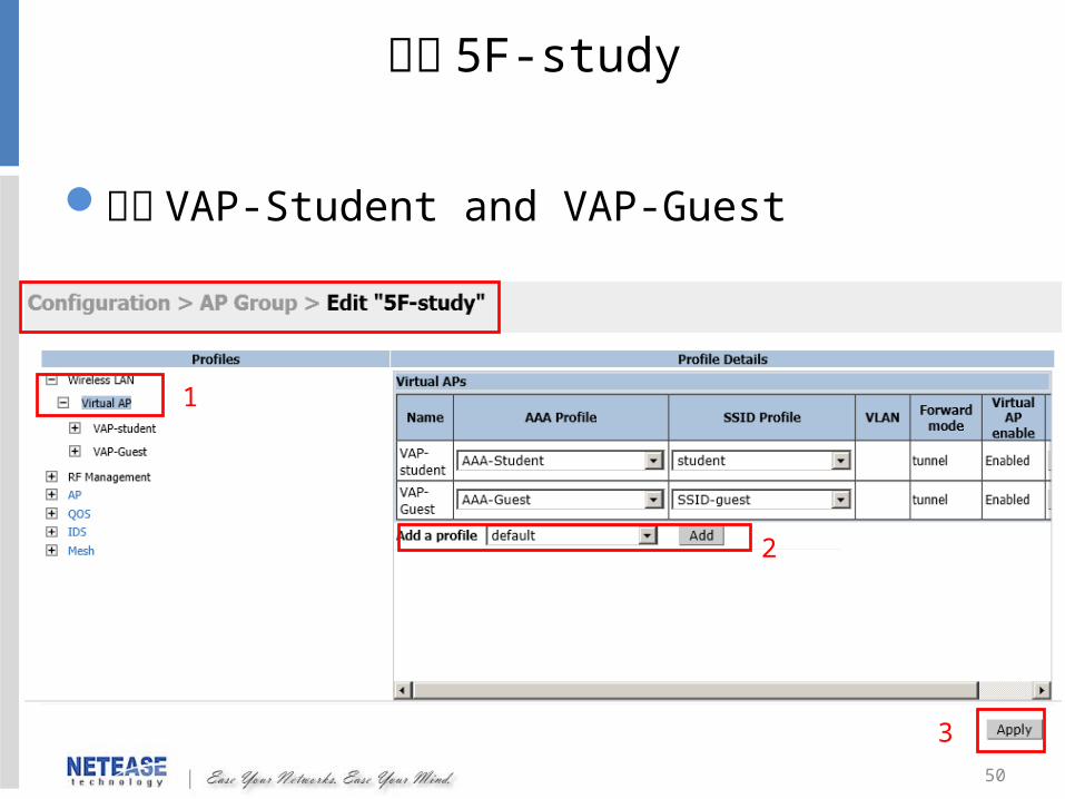
編輯 5F-study
新增 VAP-Student and VAP-Guest
1
2
3

51
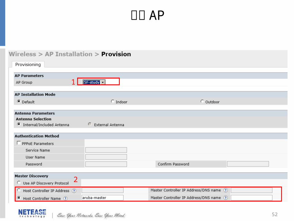
設定 AP
將 AP 加入 Group
3
25
4
1
52
設定 AP
2
1
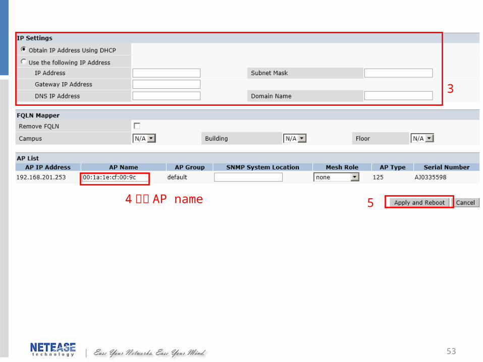
53
3
4 修改 AP name 5

54
MESH 設定
55
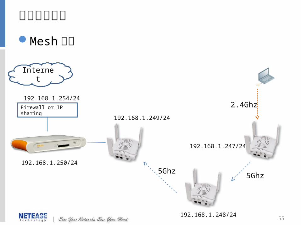
範例架構說明Mesh 架構
Firewall or IP sharing
Internet
5Ghz
2.4Ghz
5Ghz
192.168.1.250/24
192.168.1.254/24
192.168.1.249/24
192.168.1.248/24
192.168.1.247/24

56
設定步驟設定mesh profile新增 Group設定 AP查看mesh 訊息
57
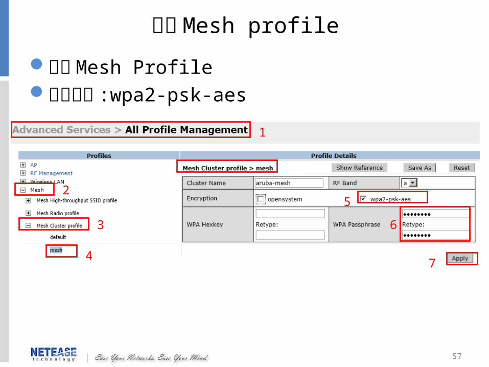
設定Mesh profile
新增 Mesh Profile 設定加密 :wpa2-psk-aes
5
4
3
2
1
7
6
58
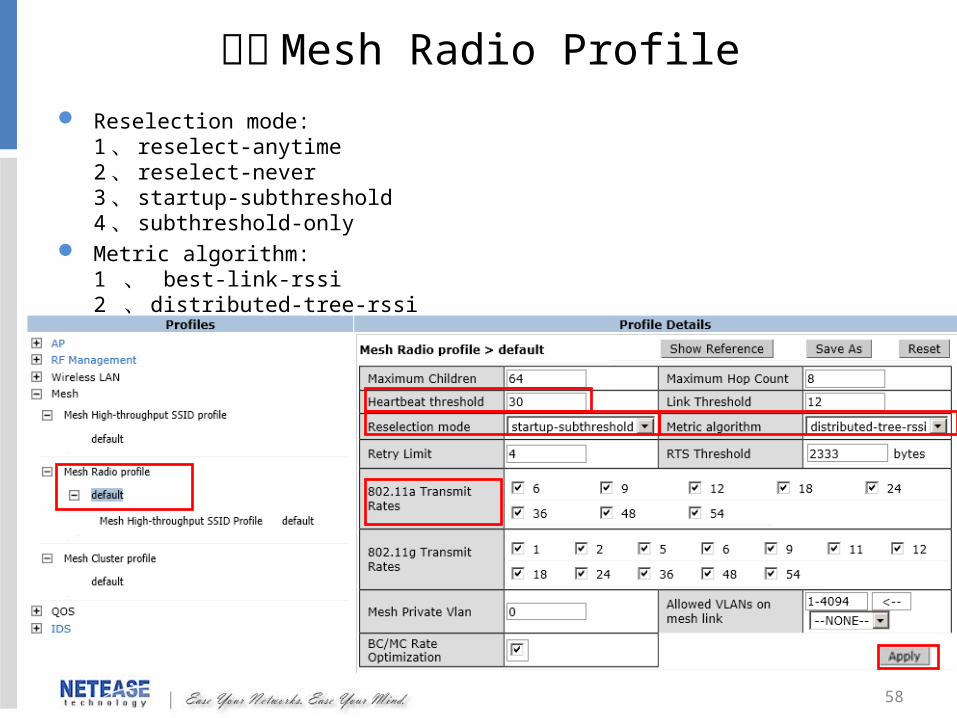
編輯 Mesh Radio Profile
Reselection mode:1 、 reselect-anytime2 、 reselect-never3 、 startup-subthreshold4 、 subthreshold-only
Metric algorithm:1 、 best-link-rssi 2 、 distributed-tree-rssi
59
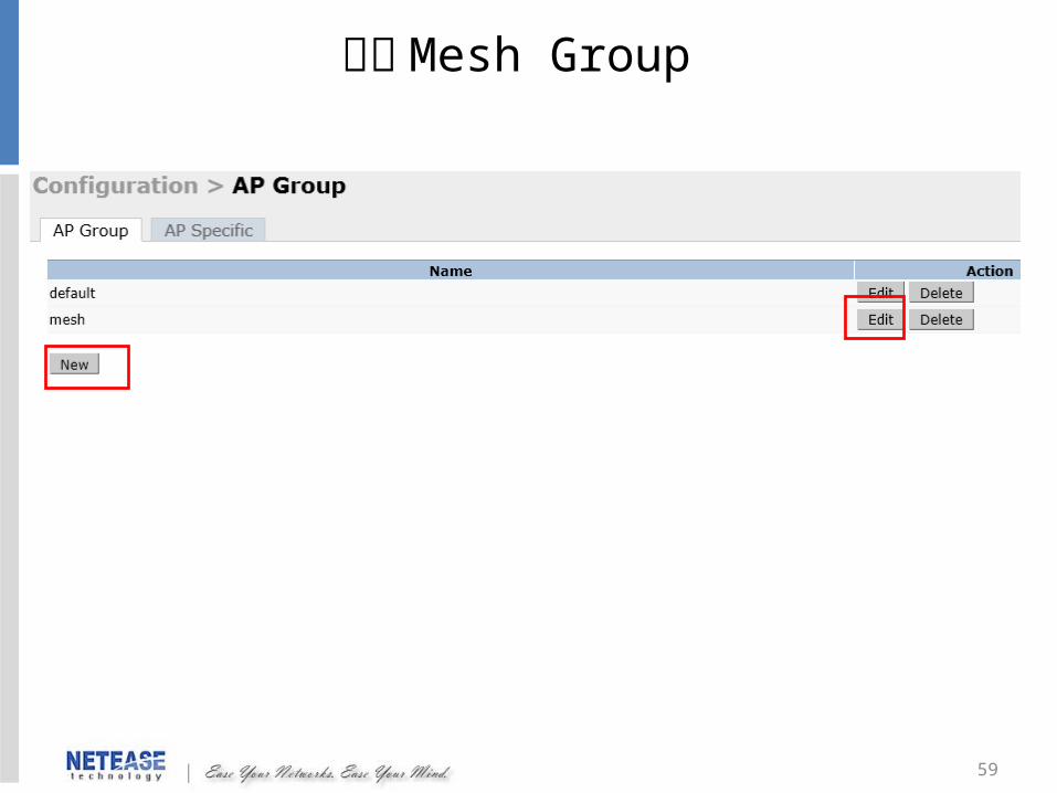
新增 Mesh Group
60
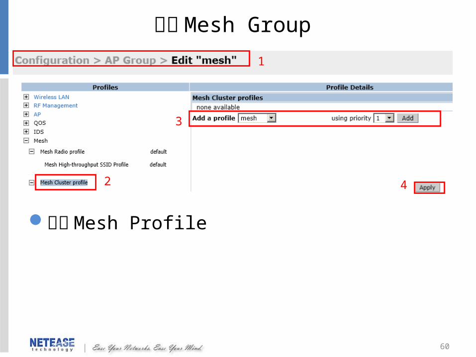
編輯 Mesh Group
新增 Mesh Profile
1
2
3
4
61
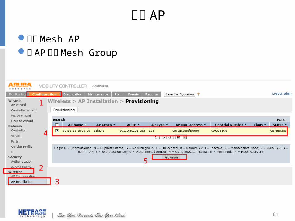
設定 AP
新增 Mesh AP將 AP 加入 Mesh Group
3
25
4
1
62
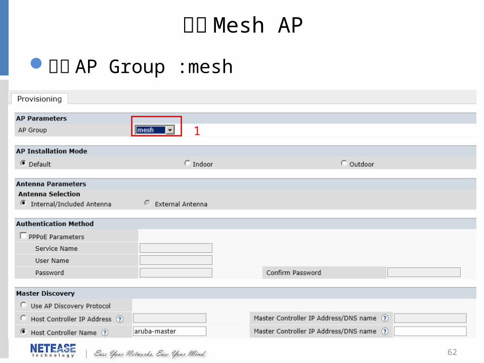
設定 Mesh AP
選擇 AP Group :mesh
1
63
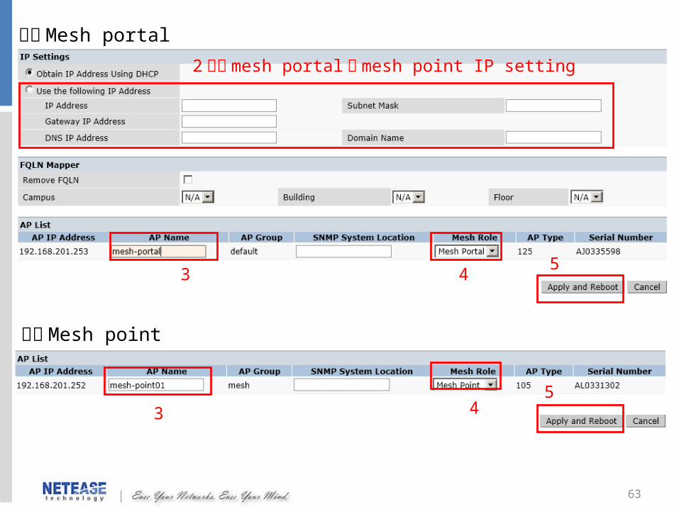
設定 Mesh portal
設定 Mesh point
2 設定 mesh portal 及 mesh point IP setting
3 45
3 45
64
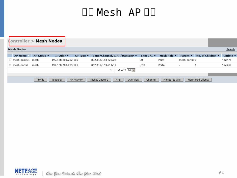
觀察 Mesh AP 狀態
65
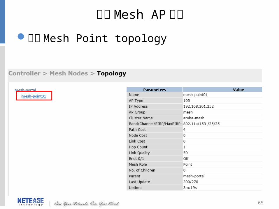
觀察 Mesh Point topology
觀察 Mesh AP 狀態

66
使用 CLI 觀察 Mesh AP 狀態#show ap mesh topology#show ap mesh active
觀察 Mesh AP 狀態
67
AP 設定
68
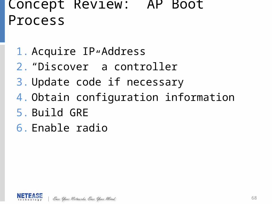
Concept Review: AP Boot Process
1. Acquire IP Address
2. “Discover” a controller
3. Update code if necessary
4. Obtain configuration information
5. Build GRE
6. Enable radio
69
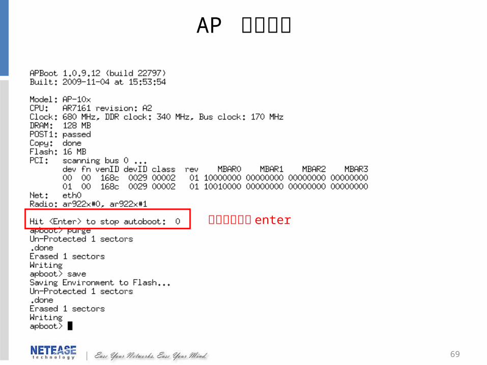
AP 開機畫面
請在二秒內按 enter
70
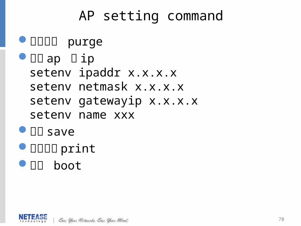
AP setting command
清空指令 purge修改 ap 的 ip
setenv ipaddr x.x.x.xsetenv netmask x.x.x.xsetenv gatewayip x.x.x.xsetenv name xxx
存檔 save顯示設定 print重開 boot
71
除錯及查看訊息
72
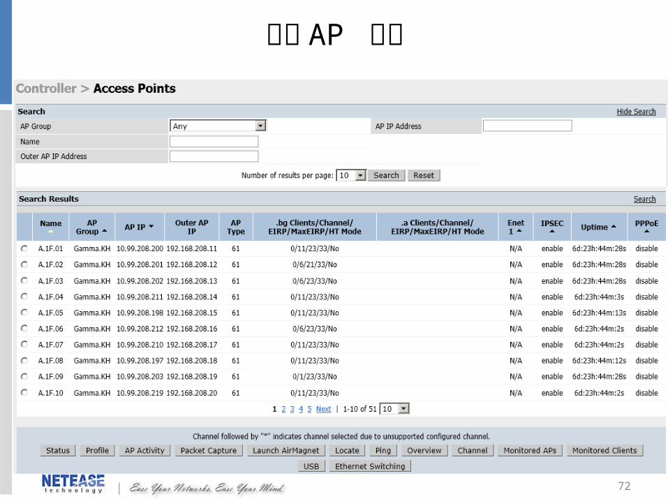
查看 AP 狀態
73
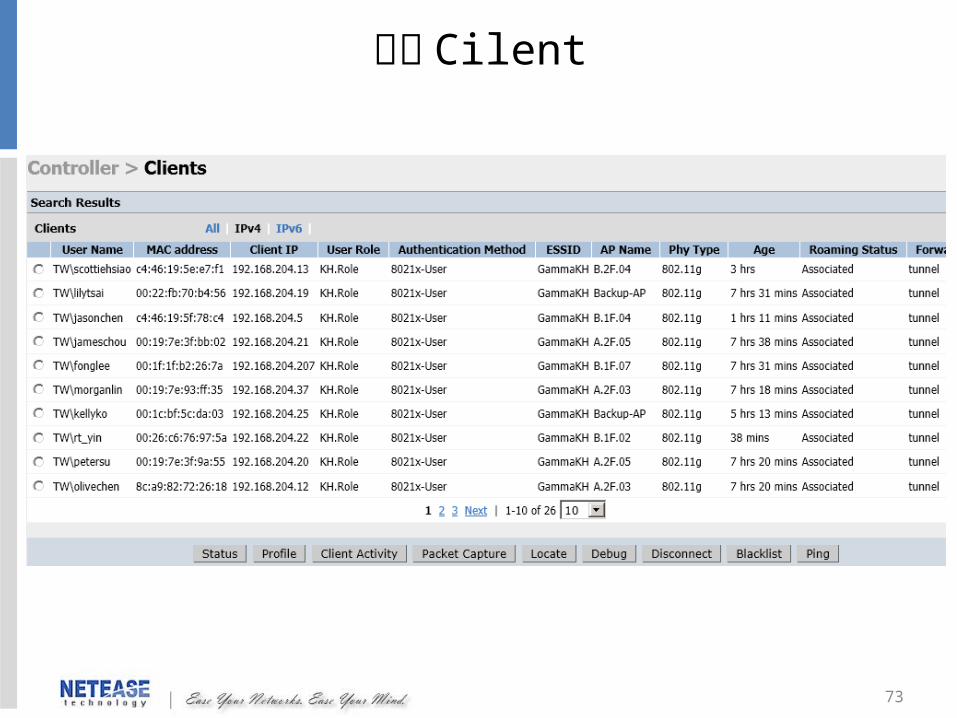
查看 Cilent
74
備份設定檔及更新韌體
75
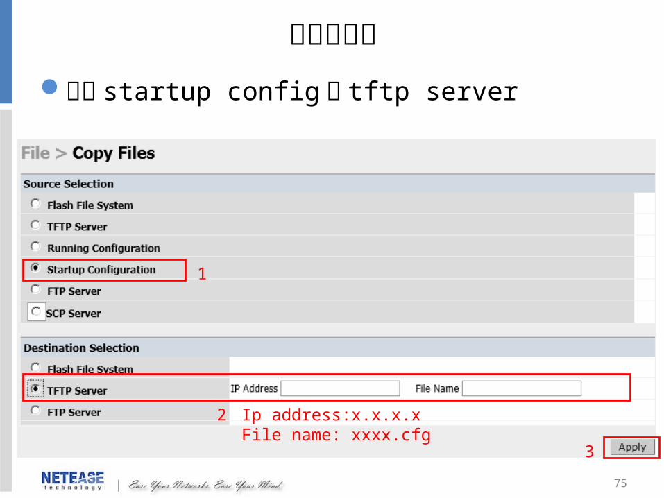
備份設定檔備份 startup config 至 tftp server
1
2 Ip address:x.x.x.xFile name: xxxx.cfg
3

76
回復設定檔
1
3
2
77
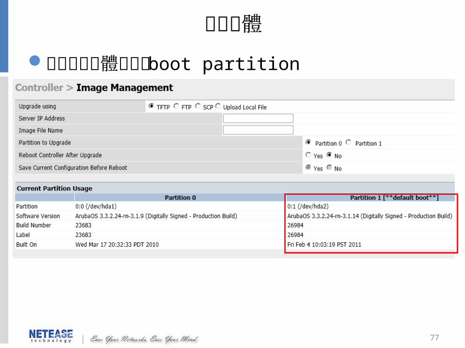
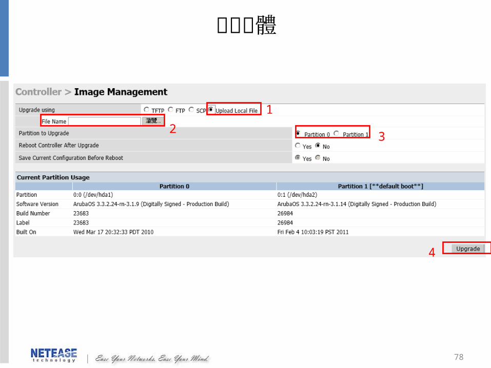
更新韌體檢查目前韌體使用的 boot partition
78
更新韌體
1
32
4
79
Q&A

80
THANK YOU !!


![無線ケーブルモデムゲートウェイ BCW700J 設定マニュアル無線ケーブルモデムゲートウェイ BCW700J 設定マニュアル ... 設定 [] []](https://img.dokumen.tips/doc/110x75/60c5706cebf8f77e29494ca5/ccffffffff-bcw700j-effff-ccffffffff.jpg)