Embed Size (px)
Citation preview
www.gott.com.my
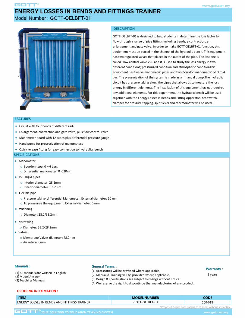
ENERGY LOSSES IN BENDS AND FITTINGS TRAINER Model Number : GOTT-OELBFT-01
YOUR SOLUTION TO EDUC ATION TR AINING SYSTEM www.gott.com.my
ORDERING INFORMATION :
ITEM MODEL NUMBER CODE GOTT-OELBFT-01 200-018
* Proposed d esign only , subject to ch anges without any notic e
Man uals :
( 1) All manuals are written in English( 2) Model Answer ( 3) Teaching Manuals
G eneral Terms : ( 1) Accessories will be provided where applicable.( 2) Manual & Training will be provided where applicable.( 3) Design & specifications are subject to change without notice.( 4) We reserve the right to discontinue the manufacturing of any product.
Warranty :
2 years
ENERGY LOSSES IN BENDS AND FITTINGS TRAINER
FEATURES
Circuit with four bends of different radii
Enlargement, contraction and gate valve, plus flow control valve
Manometer board with 12 tubes plus differential pressure gauge
Hand pump for pressurization of manometers
Quick release fitting for easy connection to hydraulics bench
DESCRIPTION
GOTT-OELBFT-01 is designed to help students in determine the loss factor for flow through a range of pipe fittings including bends, a contraction, an enlargement and gate valve. In order to make GOTT-OELBFT-01 function, this equipment must be placed in the channel of the hydraulic bench. This equipment has two regulated valves that placed in the outlet of the pipe. The last one is called Flow control valve VCC and it is used to study the loss energy in two different conditions; pressurized condition and atmospheric conditionThis equipment has twelve manometric pipes and two Bourdon manometric of O to 4 bar. The pressurization of the system is made as air manual pump.The hydraulic circuit has pressure taking along the pipes that allows us to measure the loss energy in different elements. The installation of this equipment has not required any additional elements. For this experiment, the hydraulic bench will be used together with the Energy Losses in Bends and Fitting Apparatus. Stopwatch, clamper for pressure tapping, spirit level and thermometer will be used.
SPECIFICATIONS
Manometer
o Bourdon type: 0 – 4 barso Differential manometer: 0 -520mm
PVC Rigid pipes
o Interior diameter: 28.2mmo Exterior diameter: 33.2mm
Flexible pipe
o Pressure taking- differential Manometer. External diameter: 10 mm o To pressurize the equipment. External diameter: 6 mm
Widening
o Diameter: 28.2/33.2mm
Narrowing
o Diameter: 33.2/28.2mm Valves
o Membrane Valves diameter: 28.2mmo Air return: 6mm