Embed Size (px)
Citation preview
NASA Technical Memorandum
_ :_=_ Dynamic Analysis of Free-Piston Stirling
:-: Engine/Linear Alternator-Load_ System-
Experimentally VaI_ated
M. David Kankam ....
National Aeronautics and SpaceA dministration
Lewis Research Center
Cleveland, Ohio ...._'= =_ =
Jeffrey S. Rauch
Sverdrup Technology, lnc.
Lewis Research Center Group
Brook Park, Ohio
and
- - Walter Santiago \_-- --
National Aeronautics and Space_dminjstration
Lewis Research Center _= _
Cleveland, Ohio _=:5_
- Prepared for the
27th lntersociety Energy'Conversion_E_ngineering Conference
cosponsored by the ANS, SAE, ASC, AIAA, IEEE, and AIChE
San Diego, California, August 3-], 1992
(NASA-TM-I060341 DYNAMIC ANALYSIS
ENGI NE/LINE._R ALTERNATOR-LOAD
SYSTEM-EXPER IMENTALLY VALIDATED
( NASA ) ii p
N93-22559
Unclas
G3/66 0150554
https://ntrs.nasa.gov/search.jsp?R=19930013370 2020-04-27T09:49:26+00:00Z

....... _7
,I

"Dynamic Analysis of Free-Piston StirlingEngine/Linear
Alternator-LoadSystem - Experimentally Validated"
M. David KankamNASA Lewis Research Center
Cleveland, Ohio
Jeffrey S. RauchSverdrup Technology, Inc.
Lewis Research CenterBrook Park, Ohio
Walter SantiagoNASA Lewis Research Center
Cleveland, Ohio
ABSTRACT
This paper discusses the effects of variations insystem parameters on the dynamic behavior of a Free-Piston Stirling Engine/Linear Alternator (FPSE/LA)-Ioadsystem. The mathematical formulations Incorporate boththe mechanical and thermodynamic properties of theFPSE, as well as the electrical equations of the con-nectecl load. State-space technique in the frequencydomain Is applied to the resultingsystem of equationstofacilitate the evaluation of parametric impacts on thesystem dynamic stability. Also Included is a discussionon the system transient stability as affected by suddenchanges in some key operating conditions.
Some representative results are correlated withexperimental data to verify the model and analytic for-mulation accuracies. Guidelines are given for ranges ofthe system parameters whichwill ensure an overallstableoperation.
INTRODUCTION
The free-piston Stirling engine/linear alternator(FPSE/LA) is an attractive, thermoelectric energy conver-sion system for space applications due to its potential forlong life and reliability. However, when integrated into apower system with connected load(s), system perfor-mance must be evaluated to ensure that unfavorablesystem Interactions do not occur. Treatment of suchinteractions is not commonly found in the existing litera-ture which deals mainly with establishing the engineoperating conditions (Refs.1 to 7). Additionally,a combi-nation of detailed representationsof the engtnethermody-namics and nonlinearities, and load modeling has notreceived widespread attention.
This paper describes a general dynamic analysis ofa FPSE/I_A connected to a load. The objective of thepaper is two-fold, First, the paper demonstrates theapplication of the state-space technique (Ref. 8) to modelthe dynamics of a FPSF./LA-Ioed system. This technique
is then used to predict the Impact of some key systemparameters and operating conditions on the dynamicstabilityof a Space Power Research Engine (SPRE)/I..A-load system at NASA Lewis Research Center (Ref. 9).
The mathematical model used for the FPSE Isbased on the recommendationsin Ref. 10. The analysisincorporates the engine dynamics and thermodynamics,and detailed modeling of the LA and connected load(s).The state-space formulation used in the analysis is amodern controltheory approach of representinga systemby its state variables. By definition, a minimum set of nstate variables, typically denoted by "X", is necessary fors complete description of the Internal status or state ofthe system. The state-space designates the n-variableco-ordinate space in which X ranges. The representationof the system equations by the compact state-spacemodel (SSM) permits the application of powerful vector-matrix theory,and can readily be relegatedto a computerto yield a complete description of the system.
The simulation,performed on the MATLAB software(Ref. 11), yields results in the form of root locus plots ofthe system elgenvalues (Ref. 8). The plots show themigration of the system roots caused by parametricvariations and, hence, the effects of such variations onthe stabilitymargins of the SPRE/1.A-Ioad system. Theadvantage of the frequency-domain-based elgenvalueanalysis is its single computation of the exact modes ofoscillation of the dynamic system. Also, it can comple-ment, valuably, Information obtained by time-domainsimulation and testing of a physical system. Manypracticalsystemsare nonlinear. However, the usefulnessof the lineartzed elgenvalue analysis Is Its use In identify-Ing potential worst-case operating conditions which canthen be verified by nonlinear ttrne-domain analysis and,possibly, testing. Hence, by using the appropriate inputdata, the analytic method and results such as reported inthis paper can be used to expedite, or assist in, thedevelopment of requirements for the application of aFPSE/LA In a space power system.

STUDY SYSTEM
The analytic formulations discussed in this paper
relate to a system which consists of a single cylinderFPSE connected to an LA via the engine power piston.
Figure 1 depicts a block diagram representation of the
study system. The LA output terminals in series with atuning capacitor, CT, feed through a load controller to anexternal load. The controller may be used to "dump"
excess generated electric power, in the case wherepower demand (by the external load) is tess than the
power supplied by the engine/alternator source. In thiscase, the load controller acts to maintain power balance.
When the load demand exceeds the generated power,the engine will tend to stall.
ANALYTIC APPROACH
The overall performance equations of the FPSE/LA-
load system are developed in three stages. First, the
equations describing the dynamics of the FPSE are de-rived. This is followed by the subsystem comprising the
LA, parasitic load and an external load. Finally, thecombined system equation is formulated for subsequent
analysis.
DYNAMIC EOUATIONS OF FPSE
The following simplifying assumptions are made -(1) Schmidt's thermodynamic analysis Is evoked suchthat:
(a) the displacer and piston motions and theworking space pressure are slnusoidal
(b) the working fluid obeys the ideal gas law, andexpands and compresses isothermally
(2) The working space gas pressure is constant but time-variant.
(3) The bounce space pressure balances the average
working space pressure, Hence, average positions of thepower piston, displacer and cylinder casing are stationary.
The dynamic equations of the FPSE/LA system, In-
corporating the mechanical and thermodynamic properties
of the Stirling engine, is stated tn EQ (1).
IM,,j[X] + It,,, + C+|[)<] .. [K,.,+ K,1lXl - [rd (1)
where the mechanical system matrices are:r "t
o°,p+,,+-¢P).=,m=,,x.Ira°o/kO m= J
and m o and mp are the displacer and piston masses,respectively;
IcoD Co.][CJ = dampingmatrix- LC,oc.j
and
I,, Kr_oIKJ - stiffnessmatrix K.o K.
The element Coo is the total damping coefficient ofthe displacer; that is, the sum of the displacer -to -engine
casing (or ground), C o, and the displacer-piston couplingCpo. Similarly, the total piston damping Cp, comprises
the self term Cp and piston-displacer coupling Cop.These definitions also apply to the stiffness matrix, [K_].
The external force vector [FE] consists of the displacer
and piston components FEo and FEp, respectively.Typically, F=o is nonexistent.
The matrices ICT] and [K_] are associated withthe engine thermodynamic force vector [FT] expressed
in EQ 2, The negative sign denotes the restoring natureof the force [IT].
[F,] - -IICJI_ + [K,][X]} (2)
The details of derivations of the engine equations aredocumented in Ref. 12. The force [FT] is expressed in
EQ (3), where Ao, A R and Ap are the displacer, displa-car rod and piston areas, respectively. The parameter Pcis the compression space pressure on the displacer and
piston. The term P.x is the heat exchanger pressure
difference between the expansion pressure PE and Pc.The displacer and piston components of [FT] are FTD
and F_, respectively.
IFJ • = _A.jLpc j • IA,] [P,](3)
The thermodynamic pressure P+ is assumed a linearly
dependent function mainly of position and velocity.Hence, EQ (3) may be recast into EQ (4), where the
superscript P denotes partial derivatives of the pressureterms In EQ (5).
IF,] - [AT][P,] - IAr] ([c "Jl.kl + [K3[Xll (4)
.I/
IK'1 I bPc bPc
(5)
Comoarison of EQS (2) and (4) implies the relationship of
EQ (6).
-IAa[c'] t
tc tK -" j(e)

Equation (5) requires that each of P.x and Pc must bee continuousfunction of the piston positionand velocity.
EVALUATION OF [KP)AND [CP]
The matrices[I_]and [C"}and,hence,[I_]and [CT]
may be obtalnedfromSchmldt'sthermodynamicanalysis.
However, this leads to an optimisticprediction of englneperformance,since Schmldts'sanalysisneglectsthethermodynamlcand fluidfdctlonallosses. Betterestl-
mates ofthe [K']and |C']matricesmay be evaluatedfroma more Incluslveanalysisinherentinthe GLIMPS
(Refs.13 and 14)and HFAST (Ref.15)designcodes,ortestdata.
The pressureterms P= and P_ are obtalnablefrom the designcodes,forgivenpistonand displacer
posltionsand speeds. For any Stirlingenglne,the
partialsinEQ (5)are constantwithrespecttotheenglne
dynamics and,thus,can be frozenInanalyticcomputa-tions.Additionalslmplifyingassumptionsare thatthe
_P, 8P, 8P,<x _P_x
partials _-"_o'_-"_p''_*X_'o and _ are all negligible.Substitution of the reduced EQ (5) into EQ {4) results InEQ (7), in
tor'"+'lool,1.l_-_, a-_C,l°I-+Pca.cllPc o .JLR'J["_'x; "a"x;jI.X'J
(7)
which the pressure, position and speed terms are com-plex, and can be obtained from the aforementioneddesign codes or test. Equation (7) yields a total of fourreal and imaginary equations from which the real-onlypartials are solved. Subsequently, EQS (8) are obtainedfrom EQ (6) and the resulting EQ (5). The expandeddynamic EQ (9) results from EQS (1) and (8).
ic,i -C_z -A 11p,_ A _P'_'
=, cp+zJL o o
IS',,, x,,,j oP,: A '_P,,IU'_ +"_,J
(s)
[;..,;][+]._r;::+,,lr.,l_[+,,it,,1c,,jLX,,j _jLX, j +
where
• : c.+(c,,.+c+jj
_.,j LtK. • K,,_ (K,,+K=_JThermoelectric power generation requiresconnection
of the FPSE to an electromechanlcal device, such as alinear alternator and an associated load. Modellingof thealternator-load system ts discussed next.
ELECTRICAL EQUATIONS OF LA-LOAD MODEL
An equivalent circuit diagram of the LA is shown inFig. 3. The alternator output terminals are connectedthrough a series tuning capacitor Cr to a parallelcombination of a parasitic load P+ and an externalseries RL - _ - CL static load. The capacitor CT servesto ensure an electrical resonance within the circuit and,hence, a maximum power transfer from the engine-alternator system to the connected load. The stabll_ ofthe system may be enhanced by ensuring a coincidenceor near coincidence of the electrical resonant and themechanical operating frequencies. The other parametersin the figure are the stator resistance, Re, the leakageInductance, L=, the magnetizing Inductance, Lm,and theeddy current and hystersl= lossterm Rc Inthe magneticcore of the LA.
Application of Ktrchhoff's voltage law to loops 1through 3yields EQS (10) to (12) in which the term }'
denotes --_ and,
(,';'.+_,,)_,- ,':V,.+(L.+L,,:'],- Lj,+ v_. .. (._o>
•¢1+,/1- Lj#,,. L_ "0 (11)
- e.,,,,,+ (s., + ,,_,,,.+ _t, • v_. o <',:)
In terms of the engine plston-lnduced flux change, thegenerated alternator voltage Is:

The capacitor voltages are stated in EQS (14)and (15).
_c,"i/C, O'q
_c," Uc, (is)
The term 4) ts the flux linking the N turns of theLA magnetic material. Solution Of EQS (10) to (i3)results in the derivativecurrentssummarized in EQS (16)to (le).
/,- -(_.. R,,l_,- t%4. _,_<- v<,-!, _;J oj/L.
'[ [;,]*'}/. -_R.+R_v,+rt,_,- v:, - iv L. _ _
(17)
i
i L - (Flpi s - (Rp. FILl ij. - Vc,)IL L(is)
STATE-SPACE REPRESENTAI"ION
The external force F=, (EQ (9)) on the piston is
representedby th, term (N__x_._ll,.Th, ,ystem ,tats
variablevectorIsdefinedInEQ (19).
[Xl' - [xo.t, xo.t.J,_<4vc.v_l - [x.x,x.,x.x,x,x.x_x_ (_9)
where the superscript _ denotes transposition of thevector.
Substitutionof the state variable EQ (19) into the FPSEdynamic equations (9), and into the I.A-load equations(14) to (18) yields the state-space model of EQ (20),
i_ - IAIIX]• [BllUll (20)
/[l'l - [CllX]. [DIIL_J
The elements of the 9.9 [A]-matrix of EQ (21) aredefined eadier. The selected state variables are allphysically measurable and can, therefore, constitute thesystem outputs [Y]. Thus. [Y] is 9x1 vector and the con-trol matrix [C] equals a 9x9 Identity matrix [!], If theengine oscillation Is initiated by a unity step Input to thepiston, with subsequent motion of the displacer, then theinput vector [U]T - [UoUe] = [0 1]. Hence, [D] is a 9_2null matrix.
The matrix [A] contains all the Individual and coupledvariables of the studysystem. The damping and stiffnesscoefficients contain the engine nonlinear contributions.However, the matrices [A], [B], [C] and [D] are all numeri-cally constant. Such e linear ti_e-lnvarlant (LTI) systemcan be subjected to small perturbationanalysis about anoperating point, to determine the overall system dynamicbehavior.
Evaluation of the eigenvslues of the [A]-matrixrequires knowledge of all Itselements. The only availableset of complete data pertains to the SPRE/LA systemconnected to an R-L load. The static load Is parasiticandmainly resistive with small but finite inductance. There isno separate external load as such. Furthermore, theexisting data shows no core loss resistance for thealternator model. Imposition of these simplifications onFig. 3 results in the state variable vector and systemmatrix as defined in EQS (22) and (23), where thesubscript S denotes simplified electrical model. Theseequations are used in the analysis of the SPRE/LA-Ioadsystem.
IA]"
! II I
I I
i-C,,imo ; -K._/mo
t II II I
I "c,J'_, I "_%I II i
I II I1 It I
I IJ !! II !t !I II II iI I
I !! II I
I
I
II
Ii
I
I: t_J' 'I
!I
II .C,a4mDIi
I!!
1
' /!'r, _ Nd@/L .(R,+P_/L=i ':I I! ! _p/I.tI I
i (,,,o//<! .<,..1 ':I I
;I !! I
R,_
I/i::.
I -R Ii
I
III
Il!II
I
II
IlI
I II !
I II I
I II !
I II !I !! I
I
!Il
.in.. :!I
II
I!!
-1/_ IiI1I!
II!
.i/t,
(21)

[X]_ -
o
-K.fmo
0
[A]s. -K=_/m,
0
0
[ XoXoX,X ,t, Vc:]
I1 I 0
I
i-C_,/:, t -K=/mo
I
0 0
-C_/me -K=/me
0 0
0 0
• [X_XzXzX4XIX,]
0 0 0
-C=knD 0 0
1 0 0
-C=/m, _)/m, 0
_) -(R..RL) ! -1I
I(L.,,L=,,L L i(I..*L.4LL )I(L.,'.L..4L_.
I I
I 0 11¢1 r I 0i i
(22)
m)
METHOD OF ANALYSIS
The SSM of the coupled equations are simulatedusing the MATLAB software. Variations are enforced inkey system and operating parameters to Induce s migra-tion of the system eigenvalues in the frequency plane.The effect of s parameter on the elgenvalues Is deter-mined by varying onlythat parameter about Its nominal ordesign value, while keeping all other parameters at theirnominal values. A plot of the eigenvalue movement dueto changes ina given parameter yields the correspondingroot locus.
Dynamic analysis derives its strength from its abilityto predict the time-domain behavior of an LTI system viasimple calculations in the frequency domain. This isexemplified by Fig.4 (Ref. 16) which showstime historiesfor corresponding elgenvalues in the frequency domain.The upper part of the plot Is typicallymirrored in the lowerhalf. Exponentially Increasingoscillations are evident forthe algenvalue In the right-hand plane. This dynamicInstability, in the case of a FPSE, will be equivalent to apiston overstroka. An oigsnvalue on the Jw-axis iscritically stable, since the oscillation amplitudes areconstant. This is characteristic of, and desired for aFPSE as an osolllator. An elgenvalue In the left-heedplane is dynamically stable. However, a FPSE In thismode of operation Is described es stalling or falling out,since the oeclllstlonsdecay with time.
The foregolng disousslonsare used to characterizethe simulation results.
DISCUSSION OF RESULTS
The interactionsbetween the FPSE/LA subsystemand the connected load are IllustratedFigs. 5 to 12. Thenominal and/or design values of the parameters used Inthe simulation are summarlzed in Table 1 which repre-santa the "base" or reference system. All the values
shown are measured quantities. However. zero valuesare enforced for the partials of the heat exchangerpressure with respect to the piston and displacer veloci-ties. The difficultyassociated with measurement of thesepartials casts doubt on the accuracy of their values.Unless otherwlse indicated, selected parameters arevaried from 50 to 150 percent of their nominal value, inIncrements of 25 percent. The arrows connecting the°X's" in the plots signify the directionsof the etgenvaluemovements, due to parametric changes.
BASE SYSTEM - Figure 5 shows • set of elgen-values forthe coupled FPSE/LA-Ioad system, and anotherset for the decoupled FPSE and LA-Icad subsystems.The electrical and mechanical roots for the coupled basssystem are identifiedas E, and MP and MD, respectively.The terms MP and MD refer to the piston and displacerelgenvalues, respectively. The terms EU, and MPU andMDU denote the electrical and mechanical roots for theuncoupled FPSE and I.A-Ioad subsystems. The unooupl-ing is realized by settingthe A (5,4) and A (4,5) elementsto zero In EQ (23) of the simplified electrical model.
In the case of the uncoupled subsystems, the com.puted 98.6 Hz of the electrical root oompares nearlyexactly with hand-calculated98.3 Hz from the characteris-tic equation of the electrical subsystem. The average ofthe predlcted piston and displacer frequencies IS 107.1Hz. This Is only 2 percent and 5.8 percent above thedesign and operating frequencies 105 and 101.1 Hz,respectively, of the SPRE. It Is noteworthythat the pistonroot MPU In the rlght-hand plane (RHP) is characteristicof an oscillatorwlth exponentially Increaslng amplitudestowards Its mechanical limits. This Is consistent withRedlich and Berchowitz's observation (Ref. 2).
.The coupled system shows a alight Increase In theaverage englne frequency, namely, 111 Hz. Again, thisIs within 10 percent of either the design or operatingfrequency of the SPRE. Also, the coupled engine tends
5

to reduce the margin of stability of the electrical system.However, the effect of the LA-Ioad subsystem is to pushthe MPU root to the MP position, nearly on the jw-axis.Hence, the electrical system acts as an external means
of control, and forces the engine to perform as an
oscillator. The engine is said to be critically stable in that
it oscillates with constant amplitudes. Finally, the unequalpiston and displacer frequencies indicate that in the
practical engine, the piston stored energy/energy dissipat-ed in a cycte is not necessarily the same as that of the
displacer.
The following discussions will highlight the Influenceof various parameters on the coupled system roots E, MPand MD and, hence, the system dynamic stability.
LA Resistance (R,) - Varying the alternator resis-tance from 50 to 150 percent of its nominal value has
insignificant effect on the system roots which remainalmost stationary in Fig. 6. The relatively small value of
the nominal resistance of 0.082_ may account for itsineffectiveness.
LA Leakaqe Inductance (L,) - A definite effect on thesystem roots caused by varying L_ is evident in Fig. 7.
The symbols "X" of the base system are identified by self-
directed arrows from MD, MP and E. Increasing I., from50 percent of nominal can place the piston root MP on
the jw-axis, while improving the damping of the electricalroot E The displacer root gets pushed towards the Iw-
axis, but remains tn the LHP. Further increase in L,beyond the nominal value may destabilize the engine,unless this is prevented by some external feedback
control system. Thus, the nominal L, is considered nearoptimum for the piston root.
,Tuning Capacitance (CT) - Figure 8 shows that a 50
to 150 percent variation of the nominal tuning capacitancehas an effect similar to that caused by the leakage induc-
tance. Here, the optimum capacitance for placing the pis-ton root on the W-axis ls between 100 and 112 percentof the nominal value.
Load Resistance (R 0 - The pronounced impact ofthe load resistance variation from 50 to 300 percent of its
nominal value is illustrated in Fig. 9. !ncreaslng P_.significantly improves the electrical damping, with only amodest change in its frequency. The piston root can not
only be moved past the jw-axls, but also, its frequencydecreases gradually. Initially, the frequency of thedisplacer root reduces only slightly, while Its damping
increases. Beyond 150 percent of the nominal P_, the
damping reduces with further increase in RL. Examination
of Fig. g shows that, as RL increases further, the pistonroot is pulled into the RHP, while the displacer rootmoves towards the jw-axis. These: counter-balancing
effects will tend to stabilize the engine. Since It is thelarger of the two resistances in the system, the loadresistance can mask the influence of the LA resistance.
The above observation shows that, generally, aproperly designed parasitic load may be used to force theFPSE/LA subsystem to operate as an oscillator; that is,
one eigenvalue pair on the jw-axis, and all others in theLHP.
Short Circuit Condition - A potentially hazardousoperating condition in a FPSE/LA-Ioad system is a shortcircuit of the load. This represents an extreme case of
ioadirnpodance variation. Figure 10 depicts the positionsof the system roots for such a condition. The electrical
root needy collapses on the jw-exis, without substantialchange in frequency, when compared to the base system.
With only the small alternator resistance remaining in theelectrical circuit, the shorted electrical circuit approximatesan oscillator. The piston root is forced into the RHP.
signifying exponentially increasing oscillations. Hence,the effect of • sudden short circuit condition is to render
the engine unstable, with a possible consequence of
piston overstroke, in the physical system, this situation
may result from generated energy which is dissipated ina minimum impedance of the electrical system.
Open Circuit Condition- Another possible but undesir-able operating scenario is an open circuit condition. This,
also, is an extreme form of load inpedance variation. The
electrical roots in Fig. 11 collapse onto the origin, withtheir damping capability eliminated. The engine becomes
unstable, as the piston roots are in the RHP. Thiscondition Is also possible in a practical system in which
the generated energy, in the form of power, abruptly hasno path to flow.
CONCLUSIONS
This paper uses the state-space technique to deter-
mine the effects of parametric variations on the dynamicstability of a FPSE/LA-Ioad system. The mathematical
formulation includes the major thermodynamic effects ofthe engine. The following conclusions are based on the
evaluation of stability of the SPRE/LA-Ioad system.However, the analytical approach and trends of the
results are applicable to other FPSE/I_A-Ioed systems.The results confirm Redlick and Berchowitz's classical
control theory-based result that there exists only onemode of oscillation for the FPSE. This mode ts denoted
by a pair of mechanical roots in the right side of thecomplex plane, Such roots must be forced by a controlmechanism to move onto the jw-axis, to ensure the
engine behaviour as a constant amplitude oscillator.
For a given FPSE/LA subsystem, the operatingfrequency can be load dependent. However, the effect of
the constituent load components depends on the their
relative magnitudes. A system-designed load generallyaids in stabilizing the system. Dynamic stability is
reasonably assured, if the electrical system parametersdo not change significantly from their design values. For
the system studied, the parameters with the most impact
6

on the systemstabilityare the I.A leakage Inductance, thetuningcapacitance and the load resistance.
Abnormal operating conditions, such as a suddenshort or open circuit of the load, can destabilize theengine, unless ameliorating controls are in place.
Generally, the effects of parametricvariations onthesystem dynamic stability give an insight into the engine-alternator-load interactions. This Information can bevaluable during design stage, and with respect to perfor-mance prediction to guk:lesystem evaluation In experi-mental work.
REFERENCES
1. Rsuch, J.S., "Steady-state Analysis of Free-PistonStiding Engine Dynamics," IECEC 75 Record,pp. 961-965.
2. Redlich, R.N., Berchowltz, D.M., "Linear Dynamics ofFree-Piston Stlrllng Engines," Proc. Instr. Mech.Engrs., Vol. 199, #A3, pp. 203-213, 1985.
3. Das, R.L. Bahraml, K.A., "Dynamics and Control ofStirlingEngines In a 15 KWe Solar Electric Genera-tion Concept,' Pro¢. IECEC 1979, pp. 133-138.
4. Benvanuto, G., DeMonte, F., Farina, F., "DynamicBehavior Predictionof Free-Piston StirlingEngines,"IECEC 1990, pp. 346-351.
5. Cichy, M. Carlini, M., "Frequency Dynamic AnalysisofFree-Piston Stlrling Engines," IECEC1984, pp. 1829-1835.
6. Carlini, M. Kucharski,T., "Dynamic Analysis of Free-Piston Stirling Engines by Modal Transformation
Method," Presented at SAE Intl. Congress andExposition,Detroit, MI, Feb. 24-28, 1986.
7. Chen, N.C.J., Griffin, F.P., "Linear Harmonic Analysisof Free-Piston Sttrling Engines,' ORNL/CON-172,Martin Marietta Energy Systems, Inc., Oak RidgeNatl. Lab., June 1986.
8. "Modem Control Theory', Book, by W.L. Brogan,Prentice-Hall Inc., 1982.
9. "Space Power Demonstrator Engine', Phase I FinalReport, NASA Contractor Report 179555, May 1987.
10. Kankam, M.D., Rauch, J.S., "Comparative Survey ofDynamic Analyses of Free-Piston Stirling Engines,"IECEC, August 1991, Boston/NASA TM-104491,1991.
11. "MAC II MATLAB," Copyright The Mathw0rk, 1987,1988.
12. Rauch, J.S., Kankam, M.D., "Free-Piston StirlingEngine Dynamics," NASA TM, 1992.
13. Gedeon, D., "AGlobally - Implicit StirllgCycle Simula-tion,' 21st IECEC, Vol. 1, 1986, American ChemicalSociety, pp. 550-556.
14. Gedeon, D., 'GLIMPS Version 4.0 User's Manual,"1992, by Gedeon Associates.
15. Huang, S.C., 'HFAST-A Harmonic Analysis Programfor Stiding Cycles," 27th IECEC, Aug. 1992, SanDiego.
16. 'Subsynchronous Resonance," Seminar Notes,General Electdc Company, 1979.
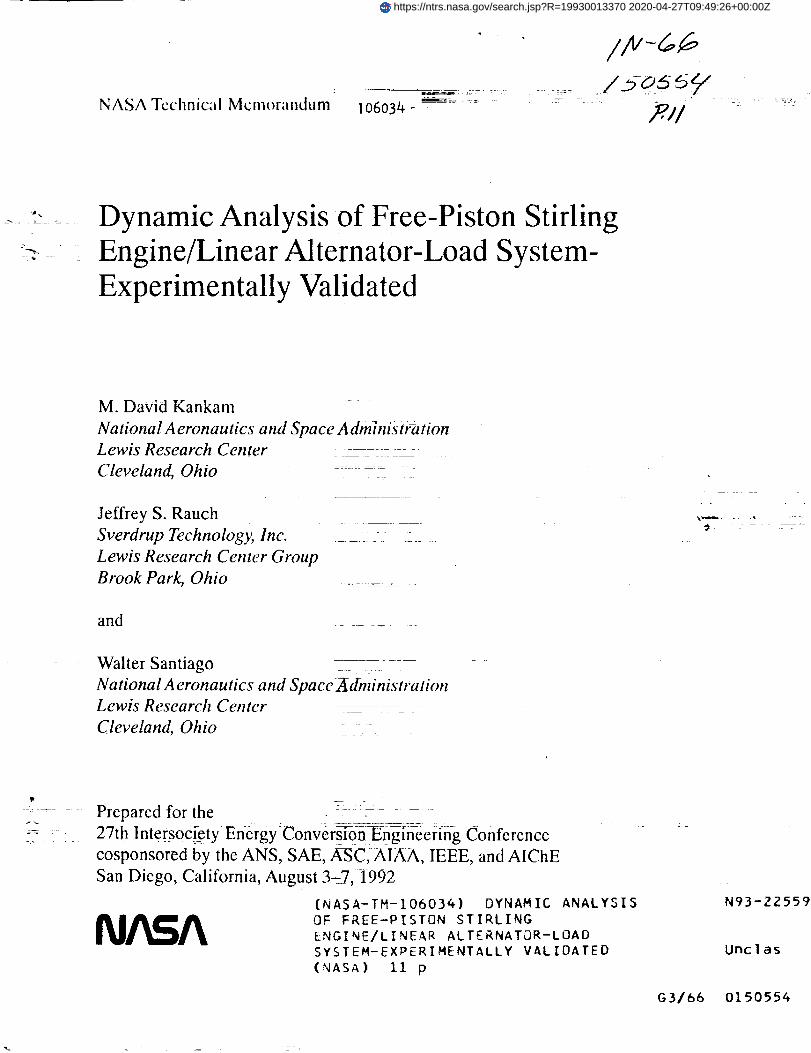
Figure1- _lock diagramrepresentation ol studysystem.
.=,,=,.a*=*=m=..,.F
"_""J-11_!l-_ ,,..--
.... _#=ctrMj_toh:I _ rod
Fig 2
_,ou_q
Schem_iic b] a SFngle _yllnder
Fr_ee-PiStOn Stirling Engine
Infem_] fo LA _ _ E=cfehn_t TO L_i
.. .. F_ I c_ ,.o.
I 1 ® -'o,-T_/;,I PlUt$_L¢ (¢ttmtl
L_d Leid
Figure3- Equivalent_cuit of linearalternator(LA)-Ioadsystem.
I00
6oo
4OO
20c
!°-2OO
,.400
-6OO
"%o
I00
60O
40O
2OO
E-200
,.,zoo
-60O
| i,.%
('Hzs _) uP , MP "_'Oe3 HZ
(N.eH=)EU. _i_(Io7.8_z) _o64 _z'
(m24Hz)
EJiectr_1 roo_$: Me.torte roots 1
I_ MPU• |
i
._o :i_o ._o o _o-_0 -2OO
Fig. 5 Plot of coupled ==nOcSecoul_d system eigenvaiues
MD •
(_,. _--so% _. =s_.) ;I::
. Mec. sy't ro_
E
lip
ME)._o ._oo ._o -_oo ._o o
rtl_m=(-hcc)
Fig, 6 PlOt of system etgenvalues with Re variatiorl
5o
SOO ....
i--_, _ F-'=
9
0
Fig. 4 Bustrating modal responses =_W.,(:_:)of eigenvatues Fig ? Plot of system eigenvalues with IJ variation
6.s - _ --*150% Nora., 25%
---_/ M- _eh _¢t _
" ' "'._ .i_o .ioo -_o ._® ._o5O

|.L
60O
4OO
200
-2C
.4CX
-600
.s.%
(CT = 50% --H50% Norn, 12.5%)
M. mech ly_ mixE. dec. lys. root
[
, _ M_"-250 .200 -150 -I00 -50 0
sii_ (l/see)
Fig. 8 Plot of system eigenvalues with CT variation
8OO
6OO
4OO
2OO
'.%o
• MS) ,laP
E 71
M • mec_ Wt toolE - dec syL mot
'MS *MP
.250 -200 -150 .tO0 -50 0
sii_na (l/sic)
Fig.11 Plotof systemelgenvalueswithopen circuit
50
8O0
4O0
2OO
.L-200
-400
-6O0
.L-200
-400
-600
-80C-50
(RL = 50% -_500_ Nora, 25%) E
air,"
M. mec_ lyl, rootE - ebc. Ws. mot
_r'"e_-"*'e" -- "4 | I :
-2S0 -200 .l.SO -100 -_0 0
silp_a (-h,cc)
Fig.9 Plotof systemeigenvalueswithRLvariation
,'MC)
M • mech. sys rootE. qdec lys root
M D
i
E
E
• MD • MP
_o .3o ._o .1o o :o _o _ 4o
sil_ it/sic)
Fig. 10 Plot of system eigenvalues with short circuit
50
so
9
Table 1 Summary o! System Parameters
. S_b_l Vllu_ ,it D'scrtrtloa
i 1.701 (kH L0tsplscer mss
t.N4 (q) i I'tst_ rossIt4.&) • 1@_ (l_] P(stmt erel141,11 _ tO-' i_) 911p1Ket irel|.M7 • |0 _ {m') P|ltM _ Iris
r_ II,IHit • l0 s (K/s} Dtlpllci_ tess1 stlffMss CNff|Clint$4._ (l(._/u) Ollp1Ker tits1 _tmS ¢etfflctentr_ )|,lOS s IO" (N_} PIItea total ittfrn4ss ¢m4ff|cteatC,p 60.15 (II.S/B) Plltim tetil d_lql ¢0¢fflc|est
I (It/I) OtlplKcr-plstm Cm_llnll st|ffmesl¢oeff I¢lqmt
I (It/i) plstos-dlip1Ker ¢qm_||l_ stifraesl:eiffl¢tHt
C_ 0 (N.S/D) 0_lplicir-ptstee ¢ewtl_0 d_Pt_ll clsef-ftcieltt
(_ O (IhS/I) Ptsto_-dt|pl_e_ cewllq 6wtq ¢s_f-ftctnt
ilili.,| S |0 _ (N_) £Oq_SSIO_ I_KI iwlssvre ¢JUm_* vltk_lste_ pelltlw
-/4.N S i0 i (li/l_) dtsFlicirC_ressie_l_s_t_emsI prtssvr¢ ¢l_lr_i with
O (li.S/_) £wesl_ sPiCe pressure cl_q_ _ttk_tst_ wl_tty
0 |l.f_) Compretllm Spiel ;ressvr_ Ctiqe v|tkdtspIKir v_lKttyMeat eschl • p_isvre cks._ vttk
dt splicer _lt t |ee_._ II (II.S/IP) Neat il¢lsln_i'lr IWIIS|U_I eight[re _ltk
dlll)l lCl_" ¥1|Ktt_
0 (II.S/s _) melt *schiller ps_sllml cker,_ vttkpt It ol_ _r_lK I tJr
J#-__ 4S.S [V-_) Negnett¢ ftw Ilidul_¢ ckc_e vttk pfs-a_ t_ posit I¢_
O._ (O] t_ ut'_l=g _stst_n(iI.IS [oN] U_ |elks IMKtI_i
Tun( Iql r_c I times
_1_ !.66S5 (9 I_lll _slstser¢!O.Ill (oN L_I Imb,Kt_¢a
Form Approved
REPORT DOCUMENTATION PAGE OMB No 0704 OI8B
Public rt_l:.odintl L_fdeJ_ lot Ibis t-ollecl_o, of ktl,._rmal_.lt is eshmalnd Io avurLigl_. !hotti" por ro'.;l:x_nso. Inchlding lira llme lOT rl_vtewtrlg tnshucliorls, soillchn_l Oxmhe_! (liilil _.otlet'_s.
gathorlng ae_l malr'Aalni_g the data needed, and comploling Lind eevluwlr_g the collectk_n ol into/maliGn Send commonls regarding this burden estimale or ,lny ollm.r .lSl_,_.cl ol Ibis
collection ot information, Including suggestions for reducing this burden, to WLishtnglon Headquarters Servzces, Directorate for llff(_'mallon Operations and Reports. 1215 Jener_,on
Davis Highway, Suite t204, Arlinglon. VA 22202-4302, and to the Office of Management and Budget, Paperwork Reduction Prc_ect (0704-01B8). Washington, DC 20503.
1. AGENCY USE ONLY (Leave blank) 2. REPORT DATE 3. REPORT TYPE AND DATES COVERED
August 1992 Technical Memorandum4. TITLE AND SUBTITLE 5. FUNDING NUMBERS
Dynamic Analysis of Free-Piston Stirling Engine/Linear Alternator-Load
System-Experimentally Validated
6. AUTHOR(S)
M. David Kankam, Jeffrey S. Rauch, and Walter Santiago
7. PERFORMINGORGANIZATIONNAMEIS)ANDADDRESS(ES)
National Aeronautics and Space AdministrationLewis Research Center
Cleveland, Ohio 44135 - 319 !
9. SPONSORING/MONITORING AGENCY NAMES(S) AND ADDRESS(ES)
National Aeronautics and Space AdministrationWashington, D.C. 20546-0001
WU-590-13-11
8. PERFORMING ORGANIZATIONREPORT NUMBER
E-7017
10. SPONSORING/MONITORINGAGENCY REPORT NUMBER
NASATM- 106034
11. SUPPLEMENTARY NOTES
Prepared for the 271h lntersociety Energy Conversion Engineering Conference cosponsored by the ANS, SAE, ASC, AIAA, IEE'E, and AIChE,
San Diego, California, August 3-7, 1992. M. David Kankam, NASA Lewis Research Center, Cleveland, Ohio; Jeffrey S. Rauch, Sverdrup
Technology, Inc., Lewis Research Center Group, 2001 Aerospace Parkway, Ohio 44142; and Waiter Santiago, NASA Lewis Research Center,
Cleveland, Ohio. Responsible person, M. David Kankam, (216) 433-6143.12a_ DISTRIBUTION/AVAILABILITY STATEMENT
Unclassified - Unlimited
Subject Category 66
12b. D_STRmUTION CODE
13. ABSTRACT (Maximum 200 words/
"]'his paper discusses the effects of variations in system paramelers on the dynamic behavior of the Free-Piston
Stifling Engine/Linear Alternator (FPSE/LA)-Ioad system. The mathematical formulations incorporate both themechanical and thermodynamic properties of the FPSE, as well as the electrical equations of the connected load.State-space technique in the frequency domain is applied to the resulting system of equations to facilitate the evalua-
tion of parametric impacts on the system dynamic stability. Also included is a discussion on the system transientstability as affected by sudden changes in some key operating conditions. Some representative results are correlated
with experimental data to verify the model and analytic formulation accuracies. Guidelines are given for ranges of
the system parameters which will ensure an overall stable operation.
14. SUBJECT TERMS
Free-piston Stirling engine/LA-Ioad; Dynamic stability; System analysis; Mathematicalmodels; State-space technique
17. SECURrrvemSStFICA'nON ln. SECURrrvCt._SSlRCATtON _9. SECURrrvCLASSIF=CATIONOF REPORT OF THIS PAGE OF ABSTRACT
Unclassified Unclassified Unclassified
NSN 7540-01-280-5500
15. NUMBER OF PAGES
1016. PRICE CODE
A02
20. LIMITATION OF ABSTRACT
Standard Form 298 (Rev. 2-89)
Prescribed by ANSI Std Z39-18

![The Free Rider Problem: a Dynamic Analysiseconweb.ucsd.edu/~jwatson/PAPERS/SWET2012/Salvatore... · equilibria in dynamic free rider problems. Levhari and Mirman [1980] present a](https://img.dokumen.tips/doc/110x75/5fb0e28e5497c21ebb5bdc2c/the-free-rider-problem-a-dynamic-jwatsonpapersswet2012salvatore-equilibria.jpg)