Embed Size (px)
Citation preview
www.Duratrax.com
®

2
These are included with your Evader EXT2.4.
ChassisBody
Transmitter7.2V 1500mAh NiMH Battery
7.2V Charger
AA Batteries (8)Receiver Antenna TubeInstruction ManualReplacement Parts Guide
IMP
OR
TA
NT
SAFETY PRECAUTIONS:When the safety precautions are followed, the Evader EXT2.4 will provide years of enjoyment. Use care and good sense at all times during operation. Failure to use this vehicle in a safe, sensible manner can result in injury or damage to property. You and you alone must insure that the instructions are carefully followed and all safety precautions are obeyed.
➤ Do not operate the Evader EXT2.4 near people. Spectators should be behind the driver or at a safe distance away from the vehicle.
➤ Do not leave any charger unattended during charging. If the battery or charger become hot at any time, disconnect the battery from the charger immediately! Failure to do so may cause permanent damage to the charger and battery and may cause bodily harm.
➤ The Evader EXT2.4 features waterproof electronics that allow you to run in almost any conditions. However, to achieve long life, avoid immersing them completely in water. After you are fi nished running, make sure that the electronics are dry to help avoid corrosion.
➤ Always turn on the transmitter before turning on the electronic speed control.
HELPFUL HINTS:➤ Avoid working over a deep pile carpet. If you drop a small
part or screw, it may be diffi cult to fi nd.
➤ Place a mat or towel over your work area. This will prevent parts from rolling off and will protect the work surface.
➤ Avoid running the Evader in cold weather. The plastic and metal parts can become brittle at low temperatures. In addition, grease and oil become thick, causing premature wear and poor performance.

3
SPECIFICATION AND DESCRIPTION CHANGES:All pictures, descriptions and specifi cations found in this instruction manual are subject to change without notice. Duratrax maintains no responsibility for inadvertent errors in this manual. Visit Duratrax.com for the latest updates and information for your model.
WARRANTY:➤ Duratrax® guarantees this kit to be
free from defects in both material and workmanship at the date of purchase. Duratrax will warranty this kit for 90 days after the purchase date. Duratrax will repair or replace, at no charge, the incorrectly made part.
➤ Make sure you save the receipt or invoice you were given when you bought your model! It is your proof of purchase and we must see it before we can honor the warranty. Further, Duratrax reserves the right to change or modify this warranty without notice.
➤ In that Duratrax has no control over the fi nal user assembly or material used for fi nal user assembly, no liability shall be assumed nor accepted for any damage resulting from the use by the user of the fi nal user-assembled product. By the act of using the user-assembled product, the user accepts all resulting liability.
To return your Evader EXT2.4 for repairs covered under warranty you should send your Evader EXT2.4 to:
Hobby Services3002 N. Apollo Drive Suite 1Champaign, Illinois 61822Attn: Service Department
Phone: (217) 398-0007 9:00 am-5:00 pm Central Time M-F
E-mail: [email protected]
If the buyer is not prepared to accept the liability associated with the use of this product, the buyer is advised to return this kit immediately in new and unused condition to the place of purchase.
STRESS-TECH PARTS GUARANTEE:We have engineered the Evader EXT2.4 to take the rough and tumble abuse that makes R/C fun. We are so confi dent of the quality and durability of the Stress-Tech plastic parts that we will replace any Stress-Tech plastic part you break during the fi rst 12 months you own the Evader EXT2.4. Just send in the part to us and we will send you a FREE replacement. Please see the Evader EXT2.4 parts list for the items covered under the Stress-Tech guarantee.To receive your free replacement part please send the following to the Hobby Services address listed above.
➤ 1. The broken part must be included.➤ 2. The part number and description of
the broken part.➤ 3. Copy of your dated invoice or
purchase receipt.➤ 4. Your name, phone number and
shipping address.
REPAIR SERVICE:Repair service is available anytime.
➤ After the 90 day warranty, you can still have your Evader EXT2.4 repaired for a small charge by the experts at Duratrax’s authorized repair facility, Hobby Services.
➤ To speed up the repair process, please follow the instructions listed below.
1. Under most circumstances return the ENTIRE vehicle. The exception would be sending in a Stress-Tech part. See the instruction under the Stress-Tech Guarantee.
2. Make sure the transmitter is turned off, and all of the batteries are removed.
3. Send written instructions which include: a list of all items returned, a THOROUGH explanation of the problem, the service needed and your phone number during the day. If you expect the repair to be covered under warranty, be sure to include a proof of date of purchase (your store receipt or purchase invoice).
4. Send to Hobby Services at the address shown. When shipping your item(s) to us, we recommend that you insure it and use a company that offers a tracking service (such as Federal Express Ground or UPS Ground).
Our staff will carefully inspect your item and notify you of their fi ndings, at which time you will be notifi ed of your options for return, repair, or replacement. Please note that items sent back unrepaired will still carry a service charge and return shipping.
Hobby Services accepts Visa® and Mastercard®, or you can send in a check. Additionally we can return the item C.O.D., but additional charges apply.
IMP
OR
TA
NT
44
FIN
ISH
ING
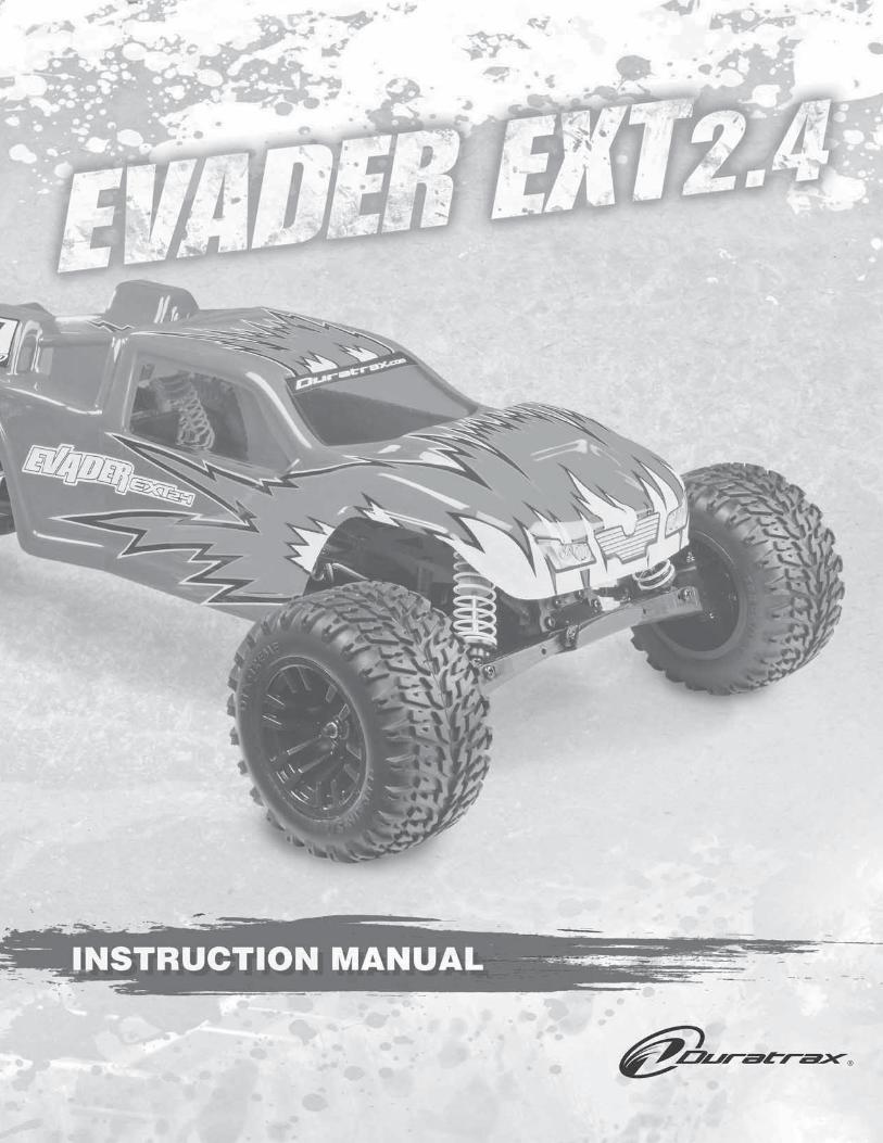
3. INSTALL THE RECEIVER ANTENNA
Do not cut the antenna wire!
2. INSTALL THE TRANSMITTER BATTERIES
+–
AA BATTERIES x4
4. INSTALL THE BATTERY
Plug battery into ESC.
1. CHARGE THE BATTERY
7.2 VOLT 2-3HOUR CHARGER
USE ONLY TOCHARGE 7.2vNiM
H OR NiCdRECHARGEABLE
BATTERIES
1. Plug the charger into a wall outlet. Connect the battery to the charger. Do not force the plugs.
2. Charge the battery until it just feels warm to the touch and then unplug. A fully discharged battery may take up to 3 hours to charge.
NOTE:Never leave a charging battery unattended!If the battery becomes hot, disconnect immediately!

5
THE EVADER EXT2.4 ESC IS SELF-SETTING.
1. Set throttle trim to neutral and turn on the transmitter.
2. Press the ESC on/off button. The LEDs will light, one green, one red.
3. Wait 3 seconds, the LEDs will change to blue. Your ESCis now set.
4. The ESC has an automatic LiPo cut-off. One fl ashing red LED means your battery is low and the cut-off has activated.
N RST N RTH
BIND
ST-D/RTH-TRIMST-TRIM
ThrottleReversingSwitch
SteeringReversingSwitch
SteeringTrim
ThrottleTrim
SteeringDual Rate
Forward
Reverse
Forward
R
5
FIN
ISH
ING
SPRINTWP
N RST N RTH
BIND
ST-D/RTH-TRIMST-TRIM
YOUR RADIO SYSTEM IS PRESET AT THE FACTORY. IF YOU NEED TO RE-BIND YOUR SYSTEM:
1. Insert the bind plug into channel 3 of the RX.
2. Turn on ESC. The RX should start blinking.
3. Press and hold down the TX’s bind button and turn the TX on. The RX will stop blinking.4. Turn off the ESC and TX, and remove the bind plug from the RX
5. RADIO OPERATION
Always check the radio operation before each run!
SPRINTWP
LEDs On/OffButton
ESC TROUBLESHOOTING GUIDE:
IF YOUR ESC DOES NOT WORKProblem: Motor and/or steering servo are dead.➤ Recharge dead batteries.➤ Check for faulty power connections.➤ Check for a damaged connection between ESC and Rx.➤ Internal damage. Unit may require service.
ESC WORKS BUT OTHER PROBLEMS EXISTProblem: Steering servo works but motor is dead.➤ Motor brushes are dirty or the motor is bad. Clean with a motor
spray (such as Duratrax Power Shot™, DTXC2458) and re-oil the bushings or replace the motor.
➤ Check for faulty motor connections.➤ Battery not fully charged.
Problem: Overheated motor or hot power plugs.➤ Motor is geared too high. Change to a lower gear setup.➤ Binding in the vehicle’s drivetrain. Check to make sure nothing
is interfering with the model’s drivetrain.Problem: Motor runs backwards but forward LEDs are on.➤ Motor is wired backwards. Swap the motor wires.Problem: Motor runs backwards and the reverse LED is on when forward command is given.➤ Move the Tx throttle reversing switch to the opposite position,
and reset ESC.Problem: Model runs properly, then motor goes dead.➤ The built-in thermal protection may be automatically shutting
down the ESC due to overheating conditions. Check for binding drivetrain, bad motor or incorrect gear ratio. Adjust gear mesh, replace motor or change gear ratio. Allow the ESC to cool and try again.

666
MAINTENANCE TIPS:Before Each Run1. Check to make sure that all screws are tight and there are
not any screws missing.2. Check to make sure that the transmitter batteries are not low.3. Check to make sure that all of the moving parts move
freely and do not bind.4. Check for broken or damaged parts. Replace any broken or
damaged parts before using. Running the Evader EXT2.4 with broken or damaged parts could result in damage to other parts.
5. Check to make sure that the receiver and speed control are still properly secured to the chassis.
6. Check to make sure that all wires are properly connected.7. IMPORTANT! Check the slipper clutch setting. The Evader
EXT2.4 transmission is equipped with a slipper clutch. When properly adjusted the slipper clutch will help to extend the life of the transmission by providing a point that slips when the kit encounters bumps and jolts that would otherwise transfer strain to the internal gears. Although there is no perfect setting for every situation, following the recommended procedure on page 7 will provide a good starting point. Final adjustments will need to be made with the kit on the actual surface it will be running on.
After Each Run1. Clean any large globs of dirt, mud or debris from the
chassis and moving parts.2. Disconnect and remove the battery.3. Check for any broken or damaged parts. This way parts
may be replaced before the next run.
After Every 10 Runs1. Check the servo saver for proper operation by grasping
the servo arm and linkage and turning one of the front tires left and right. If the wheels turn without moving the linkages and servo arm, then the unit is operating properly. If the linkage and servo arm move, loosen the knurled adjustment nut on the left side servo saver shaft. If the servo saver becomes clogged with dirt, it may not work properly which could cause servo or linkage damage. The servo saver needs to be disassembled, cleaned and readjusted. To safely adjust the servo saver, loosen the knurled aluminum collar on the left side steering post completely. Then reinstall 1-1/2 turns onto the post. Retest the servo saver as described above. Adjust the servo saver tighter or looser if needed.
2. Check to make sure that the bearings are free of dirt and debris and roll smoothly.
3. Check the shocks for oil leakage. If the shocks have leaked any shock fl uid out, you should properly refi ll the shocks for best performance.
4. Check for proper gear mesh between the spur gear and the pinion gear.
TUNING GUIDE:When tuning the Evader EXT2.4 make sure that you have equal length shocks, camber rods and steering rods on both sides (left and right). They do not have to be the same front to rear.
CASTERCaster refers to the angle which the kingpin is at in relation to the surface when viewed from the side. 0° of caster means that the kingpin is straight up and down. The Evader EXT2.4 comes stock with 30° of caster and is not adjustable.
CAMBERCamber refers to the angle at which the tire and wheel ride in relation to the ground when viewed from the front or rear. Negative camber is when the tire and wheel lean inward and positive camber is when the tire and wheel lean outward. Typically you want 0° to 2° of negative camber. Never put in positive camber. Make sure that both sides have equal amounts of camber by keeping the camber turnbuckles equal in length.FRONT TOE-IN AND TOE-OUT
1° Toe In
Toe-in and toe-out refer to the angle which the tire is at when viewed from above. Toe-in increases stability under acceleration. However, toe-in also decreases steering when entering a corner. Toe-out will increase steering into corners, but will decrease the overall stability during acceleration. The front typically is set-up with 0° to -2° of toe-in.
WHEEL BASEFront
Long Middle Short
Two washersin front
One washereither side
Two washersin rear
Wheel base is the distance from the center of the front wheel to the center of the rear wheel. Lengthening the wheel base increases steering, but decreases rear traction as a result of increased weight distribution to the front wheels. Decreasing the wheel base will increase rear traction, but decrease steering.
2° Negative Camber
TU
NIN
G

7
TU
NIN
G
CAMBER LINK PLACEMENT
The camber link placement affects the traction and handling on rough tracks. Using a long mounting position will increase traction but decrease stability. Shortening the link will increase stability, but decrease traction.
SHOCK OILS AND SHOCK SPRINGSMany different combinations can be used between the shock oils and shock springs. Some basic guidelines are that if the rear end is stiff, the truck will have more steering and less rear traction. Stiffening the front shocks will result in less steering and more rear traction. Duratrax offers different rate (stiffness) springs to suit most running conditions. The springs are color coded for easy identifi cation:
Front Rear Silver (Extra Soft) DTXC9261 DTXC9260 White (Soft) Included Included Yellow (Medium) DTXC9230 DTXC9235 Green (Hard) DTXC9231 DTXC9236 Green (Hard/Progressive) DTXC9018 DTXC9019
Thinner shock oil will make the shocks react faster, but makes the truck less stable and may cause it to bottom out over large jumps. Thicker shock oil makes the truck smoother over large jumps and in straights, but less reactive over rough sections. We have fi lled the shocks with 30 weight shock oil, which is a good choice for most driving conditions.
FRONT SHOCK ADJUSTMENTTop Shock Outer Positions:
More Steering,Faster Suspension Reaction
Inner Mount Positions:More Slow Speed Steering
Outer Mount Positions:More High Speed Steering
Top Shock Inner Positions:Slower Steering,
Smoother Over Bumps
Moving the tops of the shocks out will increase steering and produce quicker suspension reaction, but will result in slower steering reaction. Mounting the bottoms of the shocks in the inside hole of the arms will give more slow speed steering but will take away some high speed steering.
REAR SHOCK ADJUSTMENTTop Shock Outer Positions:
More Steering,More Control Over Bumps
Inner Mount Positions:Less Steering,
Smoother Over Bumps
Outer Mount Positions:More Steering,
Less Control Over Bumps
Top Shock Inner Positions:More Rear Grip,
Smoother Over Bumps
Moving the tops of the shocks in will result in more traction in the corners and greater smoothness over the bumps. Moving the tops of the shocks out will give the Evader EXT2.4 more steering and enable it to handle large jumps better.
CLEANING TIPS1. Remove the ESC, motor, receiver and steering servo.
Wipe down using a slightly damp cloth.2. Remove the wheels and wash with water. A small scrub
brush works well.3. Rinse off the body and chassis with water.4. Wipe dry thoroughly.5. Relubricate the wheel bearings and servo saver. TIP: To
keep the metal parts from rusting, spray lightly with a light oil.6. Reassemble making sure all parts move free.
SLIPPER CLUTCH ADJUSTMENTIMPORTANT! The slipper MUST be properly set. If too tight, or locked, gear damage will occur.
Loosen Nut:More Slip
Tighten Nut:Less Slip
Slipper Adjustment Nut
1. Tighten the slipper adjustment nut all the way down.2. Loosen the adjustment nut two full turns.3. Set the kit on the work surface and try to rotate the spur
gear by hand. It should be hard to turn with both the rear wheels resting on your work surface.
4. If it turns easily the slipper adjustment nut needs to be tighter. Tighten the adjustment nut 1/8th of a turn and try to rotate the spur gear again.
5. If the gear will not turn, then the slipper is too tight. Loosen the adjustment nut 1/8th of a turn and try to rotate the spur gear again.
6. For the fi nal adjustment, use a fully charged pack. Place the Evader on the surface it will be run on and give it a short 1-2 second burst of full throttle. When adjusted correctly it should slip for 1-2 feet without the tires breaking loose. If the tires do break loose, the slipper will need to be set looser. If it slips for more than the recommended 1-2 feet, it is set too loose and will need to be set tighter.
7. Repeat each step as needed to get the desired setting.

8
MA
INT
EN
AN
CE
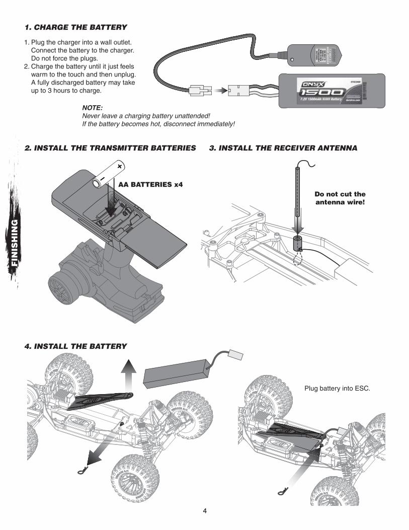
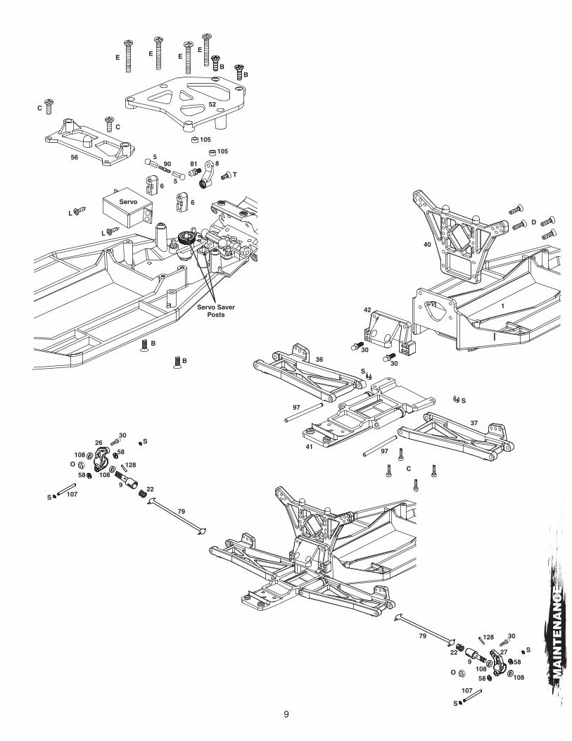
MAINTENANCE GUIDE:The following section is provided to help you with maintenance and repairs to your Evader EXT2.4.
C
57
C49
S
SK B
2
S
S81
81
50
51
104
104
38
39
103
1Y
91
94
RR
28
R
94
R
95
81
91
Y
R
95
81
24
R
28
25
105105
100
47
48
4847
102
81
81
81
81
81
43
99
46
101
98
45
44
9
MA
INT
EN
AN
CE
C
C
E E EE
BB
B
B
52
105
105
881
T
6
6
5
5
90
Servo SaverPosts
Servo
56
L
L
40
42
C
41
S
S
37
36
97
97
30
30
1
D
108
108 58
58
S
S 1079
79
22
128
26
58
58
S
S
107
108108
922
79 128 30
O
27
30
O

10
22
10
10
X
X
110
110
11
11
19
15
14
14
14
14
KeyedSection
13
13
12
18
Pin Hole
PinHole
BearingMount
22
G
G
G
P
P
P
20
217
96
108
108
108
108
11683
17
Differential
89
D
MA
INT
EN
AN
CE
88
MotorMounting
Holes
FlatArea
Motor PlateMounting Holes P
119
P
H
H
K
80

11
MA
INT
EN
AN
CE
4
S
75 (Front)76 (Rear)
Fill with oil andslowly move thepiston up and downto remove bubbles.
106
31
12232
70 (Front)71 (Rear)
34
77
78
114
114
33
35
68 (Front)69 (Rear)
Loosely install the cap.
Slowly compress the pistonto bleed out excess oil.
Tighten the cap a little at a time whilemoving the piston up and down tobleed more oil until the cap is tight.
Spur Gear
PinionGear
Motor BackLooser Mesh
Motor ForwardTighter Mesh
Motor Screw
MotorScrew
Gear Mesh1. Setting the proper mesh between the spur and pinion gears
is important. Improper mesh can result in damage to the spur and pinion gears, shorter run times and can make the motor run hot.
2. Place the scrap paper between the pinion and spur gear. Slide the motor forward so the pinion teeth mesh with the spur gears with the piece of paper pinched “tight” between them.
3. Tighten the motor screws to hold the motor in place, and slowly rotate the gears until the paper is pushed out from between the gears.
4. Rock the spur gear back and forth with light pressure. The gear should be able to move a small amount (about 1/4 of the size of one of the gear teeth) without moving the pinion.
5. Re-check the mesh after every few runs.

© 2013 Hobbico®, Inc. All rights reserved.DTXD33xxMNL