Embed Size (px)
Citation preview
18 -DIN
DUAL COLOUR DISPLAYDC PROCESS INDICATOR
Product Manual
59136-2
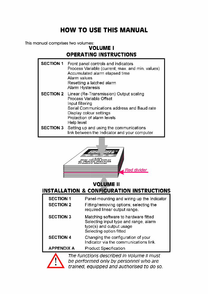
HOW TO USE THIS MANUAL
This manual comprises two volumes:

18-DIN DUAL COLOUR DISPLAY
DC PROCESS INDICATORProduct Manual
Contents - Volume I
1 OPERATION MODE 1-1
1.1 FRONT PANEL 1-1
1.2 PARAMETER SEQUENCE 1-2
1.3 INPUT OVER-RANGE OR UNDER-RANGE 1-3
1.4 SENSOR BREAK 1-3
1.5 CHANGING AN ALARM VALUE 1-3
1.6 RESETTING A LATCHED ALARM 1-4
1.7 ALARM HYSTERESIS 1-4
1.8 SUMMARY OF PARAMETER IDENTIFIERS (SECONDARY DISPLAY) 1-4
2 PROGRAM MODE 2-1
2.1 ENTRY/EXIT 2-1
2.2 PARAMETER SELECTION 2-1
2.3 EDITING THE DISPLAYED PARAMETER (EDIT MODE) 2-2
2.4 PARAMETER SEQUENCE 2-3
3 SERIAL COMMUNICATIONS 3-1
3.1 DATA FORMAT/BAUD RATE 3-1
3.2 PROTOCOL 3-1
3.3 MESSAGE FORMAT 3-1
3.4 ERROR CONDITIONS 3-5
OM091-FM Volume I (iii)
59136

1 OPERATION MODE
This mode covers day-to-day operation of the Indicator.
1.1 FRONT PANEL
1-1 Volume I OM091-1
59136
Key/Display/Indicator Function
Down key (Ú) In Edit Mode, decrements the flashing digit in the Primary Display.
Scroll key (Ø) Puts Indicator into Edit Mode; in Edit Mode, selects digit to be altered(selected digit is flashing) in Primary Display. Wrap-around occurs fromright-most digit to left-most digit.
Program Key (PGM) Selects parameter to be viewed/edited. In Edit Mode, confirms changedparameter value.
Reset key (RST) If the process variable is displayed, resets the latched Alarm 1. If theMaximum (High) Value, Minimum (Low) Value or Alarm 1 Elapsed Time isdisplayed, resets the displayed parameter.
Down (Ú) and Scroll(Ø) keys
If pressed simultaneously in Edit Mode, will abort the Edit operation andwill restore the parameter to its initial value.
Primary Display Normally displays the process variable value. Displays other OperationMode parameters when the Program (PGM) key is used. If the HelpFacility is enabled (see Subsection 2.4), this display shows the parameterdescription for three seconds before displaying the parameter value.
Secondary Display Shows a single-character identifier for the parameter value beingdisplayed (blank for process variable).
OP1 indicator ON when Alarm 1 is active.
OP2 indicator ON when Alarm 2 is active.

1.2 PARAMETER SEQUENCE
OM091-1 Volume I 1-2
59136

1.3 INPUT OVER-RANGE OR UNDER-RANGE
If the input becomes over-range or under-range, the primary display will show:
The display will disappear when the input returns within the input scale range.
1.4 SENSOR BREAK
This indicates that there is a break in the input sensor circuit.
1.5 CHANGING AN ALARM VALUE
Alarm values cannot be edited if Alarm Lock is enabled (see Subsection 2.4).
1-3 Volume I OM091-1
59136

1.6 RESETTING A LATCHED ALARM
If Relay 1 is configured to act as a latched Alarm 1 relay, when this alarm isactive, it can be reset by selecting the process variable display and then pressing the Reset (RST) key. The alarm will not be reset if the alarm condition exists at the time reset is attempted.
1.7 ALARM HYSTERESIS
The Alarm Hysteresis parameter applies a hysteresis band on the “safe” side of theAlarm value. The effect of the hysteresis value (a percentage of input span) on the operation of the different types of alarm is illustrated below:
1.8 SUMMARY OF PARAMETER IDENTIFIERS(SECONDARY DISPLAY)
OM091-1 Volume I 1-4
59136
Secondary Display Displayed Parameter
Blank Process variable
Maximum (High) value
Minimum (Low) value
Alarm 1 Elapsed Time
Alarm 1 value
Alarm 1 Hysteresis value
Alarm 2 value
Alarm 2 Hysteresis value
Total value

2 PROGRAM MODE
2.1 ENTRY/EXIT
Use the Program (PGM) key in the same way to exit Program Mode (i.e. return toOperation Mode).
2.2 PARAMETER SELECTION
2.2.1 With Help Facility Enabled
2-1 Volume I OM091-2
59136

2.2.2 With Help Facility Disabled
2.3 EDITING THE DISPLAYED PARAMETER (EDIT MODE)
OM091-2 Volume I 2-2
59136

2.4 PARAMETER SEQUENCE
The Program Mode parameter sequence is as follows:
2-3 Volume I OM091-2
59136
ParameterDescription
(PrimaryDisplay)
Parameter Description Adjustment Range
ScalingPoint 1
The first sensor input valuepoint (expressed as apercentage of input span) which is used to establisha curve for scaling sensorinput values intoengineering unit values.
0.00% to 100.00% 0.00%
DisplayPoint 1
The engineering unit value corresponding to ScalingPoint 1.
−19999 to 99999 0.00
ScalingPoint 2
The second sensor inputvalue point (expressed asa percentage of inputspan) which is used toestablish a curve forscaling sensor inputvalues into engineeringunit values.
0.00% to 100.00% 100.00%
DisplayPoint 2
The engineering unit value corresponding to ScalingPoint 2.
−19999 to 99999 100.00
The scaling process can be continued up to a total of 10 Scaling Points and 10 Display Points,until a Scaling Point is given the value 100.0%; this will be the final Scaling Point/Display Pointoffered. NOTE: Ensure that Scaling Point 1 ≤ Scaling Point 2 ≤ Scaling Point 3 etc.
DecimalPointPosition
Defines the decimal pointposition for displayedprocess variable andalarm values.
0 to 0.0000 0.0
Re-transmission ScaleMinimum
The lower end of the linear scale for there-transmission output,expressed as the valuecorresponding to theminimum output signal.
−19999 to 99999 -19999
Re-transmission ScaleMaximum
The upper end of thelinear scale for there-transmission output,expressed as the valuecorresponding to themaximum output signal.
-19999 to 99999 99999
ProcessVariableOffset
Corrects a known offset of the input in order todisplay more accuratelythe process value.
−19999 to 99999 0.00

OM091-2 Volume I 2-4
59136
ParameterDescription
(PrimaryDisplay)
Parameter Description Adjustment Range
Input FilterTimeConstant
Filters the input over auser-definable time period to minimise the effect onthe process variable ofany extraneous impulses
0.0 (OFF) to 100.0 2.0
Comm-unicationsAddress
The unique serialcommunications addressof the instrument.
1 to 99 1
Baud Rate Serial communicationsspeed
1200, 2400, 4800 or 9600 4800
DisplayColourChange
Defines the colour of theprimary and secondarydisplays prior to/after thepreset value (e.g. Alarmlevel) is reached.
Red
Green
Greento RedRed toGreen
Green toRed
Alarm Lock Enables/disables thechanging of alarm valuesvia the front panel.
Enabled
Disabled
Enabled
Help Prompt Determines whether thePrimary Display shows theparameter description for3 seconds before aparameter value is shown.
Yes
No
Yes

3 SERIAL COMMUNICATIONS
The Serial Communications option is a standard RS485 communications link. Up to 32 standard RS485 loads may be presented to a single loop on this link. EachIndicator presents ¼ standard, therefore up to 128 may be connected to a singleloop (ignoring the load presented by the master device). However, addresses arerestricted to the range 1 to 99.
3.1 DATA FORMAT/BAUD RATE
Data format is fixed at one start bit, seven data bits, 1 parity bit (even parity) and1 stop bit i.e. a 10-bit data word. Baud rates supported are 1200, 2400, 4800 and 9600. The half-duplez line turn-round time is fixed at 6ms regardless of Baud rate.The maximum inter-character delay is 120ms. The No Reply timeout is 2 seconds.
Data is expressed as a five-digit signed hexadecimal number in which thefollowing characters are permitted:
0 1 2 3 4 5 6 7 8 9 A B C D E F
Note that all the non-numeric characters are upper case. The detection of anycharacters other than these will be regarded as a syntax error. Where a valuecarries a decimal point, the point position is implicit and the responsibility forinterpreting it lies with the user.
3.2 PROTOCOL
The protocol operates on a single master basis only. All communication is initiated by the master device.
The communications addresses available are in the range 1 - 99. Address 0 isused for broadcast Parameter Write operation messages. When a message isbroadcast, the receiving instruments will attempt to implement the instruction butwill not reply.
3.3 MESSAGE FORMAT
Each message starts with a Start of Message character (L) and finishes with an End of Message character (*). A reply from the addressed instrument will contain either a positive acknowledgement or a negative acknowledgement. A positiveacknowledgement has the character A immediately preceding the End ofMessage character; a negative acknowledgement has the character Nimmediately preceding the End of Message character.
There are three message formats; they permit instrument identification, ParameterRead operations and Parameter Write operations.
3-1 Volume I OM091-3
59136

3.3.1 Form 1 Message
The master device sends a Form 1 message to ascertain whether a specificcommunications address is occupied by an instrument. If there is an instrument atthat address, a reply (with a positive acknowledgement) is received. If there is noinstrument at that address or if there is a communications link failure, no reply isreceived. The message from the master device is of the form:
Laa??*
where aa is the address (a two-digit hexadecimal number). The reply from theaddressed instrument is of the form:
Laa?A*
where aa is the same address as in the received message.
3.3.2 Form 2 Message
This message implements a Parameter Read operation. The message from themaster device is of the form:
Laap?*
where aa is the address (a two-digit hexadecimal number)
p is a single-character parameter identifier (see Table 3-1)
The reply, if the Parameter Read operation is successful, is of the form:
LaapnnnnnA*
where aa is the same address as in the received message
p is a single-character parameter identifier (see Table 3-1)
nnnnn is the data (a five-digit hexadecimal number)
If the specified parameter is invalid (e.g. not applicable to the addressedinstrument), the reply is of the form:
Laap00000A*
where aa is the same address as in the received message
p is a single-character parameter identifier (see Table 3-1)
OM091-3 Volume I 3-2
59136

3.3.3 Form 3 Message
This message implements the Parameter Write operation either on a singleaddressed instrument (address in the range 1 - 99) or broadcast to all instrumentsconnected to the master device (i.e. using address 00). Note that, with thebroadcast message, each slave instrument does not generate a reply. Themessage from the master device is of the form:
Laapnnnnn*
where aa is the address (a two-digit hexadecimal number)
p is a single-character parameter identifier (see Table 3-1)
nnnnn is the value to be written (a five-digit hexadecimalnumber)
The reply for a successful Parameter Write operation is of the form:
LaapnnnnnA*
where aa is the same address as in the received message
p is a single-character parameter identifier (see Table 3-1)
nnnnn is the value written (a five-digit hexadecimal number). Incases in which this parameter does not exist or is notapplicable for the slave instrument, this value is 00000.
Iif a valid parameter is specified with an invalid value or an error condition isencountered, the reply is of the form:
LaapnnnnnN*
where aa is the same address as in the received message
p is a single-character parameter identifier (see Table 3-1)
nnnnn indicates the error condition:
3-3 Volume I OM091-3
59136
Value Error Condition
FFFFF Value under-range
7FFFF Value over-range
7FFFE Sensor Break detected
00001 Read Only parameter
00000 Illegal value

OM091-3 Volume I 3-4
59136
Identifier Hex. Parameter Adjustment Range
: 3A Process Variable Read Only (−19999 to 9999)
; 3B Total value Read Only (−19999 to 9999)
< 3C Maximum Process Variable Read Only (−19999 to 9999)
= 3D Minimum Process Variable Read Only (−19999 to 9999)
> 3E Elapsed Alarm 1 Time Read Only (0 to 60000)
@ 40 Reset Max. PV Write resets; Read always 0
A 41 Reset Min. PV Write resets; Read always 0
B 42 Reset Elapsed Alarm 1 Time Write resets; Read always 0
C 43 Reset Total value Write resets; Read always 0
D 44 Reset Latched Alarm 1 Write resets; Read always 0
E 45 Alarm 1 value Range Max. To Range Min.
F 46 Alarm 2 value Range Max. To Range Min.
G 47 Scaling Point 1 0 to 100.00
H 48 Display Point 1 −19999 to 9999
I 49 Scaling Point 2 Scaling Point 1 to 100.00
J 4A Display Point 2 −19999 to 9999
⇓ Up to a total of 10 Scaling Points and 10 Display Points are available.⇓ Scaling Point 1 ≤ Scaling Point 2 ≤ Scaling Point 3 etc.⇓ Any Scaling Point set to 100.00% is automatically the last available.
Z 5A Scaling Point 10 Scaling Point 9 to 100.00
[ 5B Display Point 10 −19999 to 9999
\ 5C Decimal Point Position 0 (00000) to 4 (0.0000)
] 5D Re-transmitted Scale Min. −19999 to Re-trans. Scale Max.
^ 5E Re-transmitted Scale Max. Re-trans. Scale Min. To 99999
_ 5F Process Variable Offset 0 to Range Span
‘ 60 Input Filter 0 to 1000 (0.0 to 100.0s)
a 61 Colour 0 to 3 (0 = Red, 1 = Green,2 = Green/Red, 3 = Red/Green)
b 62 Alarm Lock 0 (lock enabled), 1 (lock disabled)
c 63 Help level 0 (Help enabled), 1 (Help disabled)
Table 3-1 Parameter Identifiers and Adjustment Ranges

3.4 ERROR CONDITIONS
If a slave device detects a syntax error or parity error, it will not reply to themessage; the master device should make up to two retries, applying thetwo-second No Reply timeout in each case.
Parameter Read operations with parameter identifiers which are in the legalrange but which are not applicable to the addressed instrument will have noeffect on any parameter values and a positive acknowledgement will bereturned.
Parameter Write operations with parameter identifiers which are outside the legalrange will be considered to be syntax errors; no reply will be generated.
Parameter Write operations in which the specified parameter is valid but thespecified value is invalid will generated a negative acknowledgement.
3-5 Volume I OM091-3
59136

18-DIN DUAL COLOUR DISPLAY
DC PROCESS INDICATOR
Product Manual
Contents - Volume II
1 INSTALLATION 1-1
1.1 UNPACKING 1-1
1.2 PANEL-MOUNTING 1-1
1.3 CONNECTIONS AND WIRING 1-3
2 INTERNAL LINKS AND SWITCHES 2-1
2.1 REMOVING THE INDICATOR FROM ITS HOUSING 2-1
2.2 REMOVING/REPLACING THE RELAY 2/LINEAR OUTPUT OPTION PCBs 2-3
2.3 REMOVING/REPLACING THE RS485 SERIAL COMMUNICATIONSOPTION PCB/DIGITAL INPUT OPTION PCB 2-3
2.4 REPLACING THE INSTRUMENT IN ITS HOUSING 2-4
2.5 SELECTION OF LINEAR (RE-TRANSMISSION) OUTPUT RANGE 2-4
3 CONFIGURATION MODE 3-1
3.1 ENTRY/EXIT 3-1
3.2 PARAMETER SELECTION 3-1
3.3 EDITING THE DISPLAYED PARAMETER 3-2
3.4 PARAMETER SEQUENCE 3-3
4 SERIAL COMMUNICATIONS - CONFIGURATION MODE 4-1
PM091-FM Volume II (i)
59136

Appendices
A PRODUCT SPECIFICATION A-1
A.1 DISPLAY A-1
A.2 SENSOR INPUT A-1
A.3 DIGITAL INPUT (OPTION) A-1
A.4 TRANSISTOR OUTPUTS A-2
A.5 RELAY 1 OUTPUT A-2
A.6 RELAY 2 OUTPUT (OPTION) A-2
A.7 LINEAR (RE-TRANSMITTED PV) OUTPUT (OPTION) A-2
A.8 SERIAL COMMUNICATIONS (OPTION) A-3
A.9 PERFORMANCE A-3
A.10 ENVIRONMENTAL A-4
A.11 PHYSICAL A-4
(ii) Volume II PM091-FM
59136

1 INSTALLATION
1.1 UNPACKING
1. Remove the Indicator from its packing. The indicator is supplied with apanel gasket and push-fit fixing strap. Retain the packing for future use.
2. Examine the delivered items for damage or deficiencies. If any is found,notify the carrier immediately.
1.2 PANEL-MOUNTING
The panel on which the Indicator is to bemounted must be rigid and may be up to 6mm (0.25 inches) thick. The cut-outrequired for a single Indicator is shown inFigure 1-1. Several indicators may bemounted side-by-side in a single cut-out.For n Indicators mounted side-by-side,the cut-out dimensions would be (48n - 4) millimetres or (1.89n - 0.16) inches. Themain dimensions of the Indicator areshown in Figure 1-2.
The panel-mounting procedure is shown in Figure 1-3.
CAUTION: Do not remove the panel gasket, as this may result ininadequate clamping of the instrument in the panel.
PM091-1 Volume II 1-1
59136
Figure 1-1 Panel Cut-out
Figure 1-2 Main Dimensions

1-2 Volume II PM091-1
59136
Figure 1-3 Panel-mounting

1.3 CONNECTIONS AND WIRING
The rear terminal connections are shown in Figure 1-4.
PM091-1 Volume II 1-3
59136
Figure 1-4 Rear Terminal Connections

1.3.1 Mains (Line) Supply
The Indicator will operate on 90 - 264V AC 50/60Hz mains (line) supply. The powerconsumption is approximately 4 watts.
CAUTION: This equipment is designed for installation in an enclosurewhich provides adequate protection against electric shock. Localregulations regarding electrical installation should be rigidlyobserved. Consideration should be given to prevention of access tothe power terminations by unauthorised personnel. Power should beconnected via a two-pole isolating switch (preferably situated nearto the equipment) and a 1A fuse, as shown in Figure 1-4.
If the Indicator has relay outputs in which the contacts are to carry mains (line)voltage, it is recommended that the relay contact mains (line) supply should beswitched and fused in a similar manner but should be separate from the Indicatormains (line) supply.
1.3.2 20 - 50V AC/DC Supply
Power should be connected via a two-pole isolating switch and a 315mAslow-blow (anti-surge Type T) fuse. With this option fitted, the Indicator will accept20 - 50V AC @ 50/60Hz or 20 -50V DC in the polarity shown in Figure 1-4.
1.3.3 Process Input
The process input will accept millivolt, volt and milliamp DC ranges.
1.3.4 Digital Input Option
Terminals 16 and 17, when this option is fitted, may be used for either of twofunctions (selectable in Configuration Mode); (a) Tare facility or (b) Security facility. These terminals may be connected to (a) the voltage-free contacts of a switch orrelay, or (b) a TTL-compatible voltage. With the required function selected inConfiguration Mode (see Subsection 3.4), operation is as follows:
1-4 Volume II PM091-1
59136
Voltage Free Operation TTL-conpatibleOperation Tare Facility Security Facility
Contacts open Signal >2.0V Current processvariable value used as new “zero” pointto create anautomatic offset.
Entry into ProgramMode prohibited
Contacts Closed Signal <0.6V No automatic offsetapplied.
Entry into ProgramMode permitted

NOTE: This option and the Serial Communications option aremutually exclusive.
1.3.5 Relay Outputs
Relay 1 is a standard feature; it is tied to Alarm 1. Relay 2 is an option; when fitted, it is tied to Alarm 2. The contacts are rated at 2A resistive @ 120/240V AC.
1.3.6 Linear Output
This option provides a 10-bit linear output signal representing the processvariable. The range of this output is selectable in Configuration Mode (seeSubsection 3.4).
1.3.7 Serial Communications Option
The cable used should be suitable for data transfer at the selected rate (1200,2400, 4800 or 9600 Baud) over the required distance. Transmitters/receiversconform to the recommendations in the EIA Standard RS485.
The “A” terminal on the Indicator (Terminal 17) should be connected to the “A”terminal on the master device; the “B” terminal on the Indicator (Terminal 16)should be connected to the “B” terminal on the master device; the “Common”terminal on the Indicator (Terminal 18) should be connected to the “Common”terminal on the master device.
Where several Indicators are connected to one master port, the master porttransceiver in the active state should be capable of driving a load of 120kΩ perIndicator; the master port transceiver in the passive state must havepull-up/pull-down resistors of sufficiently low impedance to ensure that it remains in the quiescent state whilst supplying up to ±100µA each to the Indicatortransceivers in the high impedance state.
NOTE This option and the Digital Input option are mutually exclusive.
PM091-1 Volume II 1-5
59136

2 INTERNAL LINKS AND SWITCHES
2.1 REMOVING THE INDICATOR FROM ITS HOUSING
CAUTION: Before removing the Indicator from its housing, ensure thatall power has been removed from the rear terminals.
To remove the Indicator from its housing, simply grip the side edges of the frontpanel (there is a finger grip on each edge) and pull the instrument forward. Thiswill release the rear terminals from their connectors in the housing and will giveaccess to the PCBs. Take note of the orientation of the instrument for subsequentreplacement in the housing. The positions of the PCBs in the Indicator are shown in Figure 2-1.
2-1 Volume II PM091-2
59136
Figure 2-1 PCB Positions

PM091-2 Volume II 2-2
59136
Figure 2-2 Removing the Relay 2/Linear Output Options PCBs

2.2 REMOVING/REPLACING THE RELAY 2/LINEAR OUTPUT OPTION PCBs
With the Indicator removed from its housing:
1. Gently push the rear ends of the CPU PCB and Power Supply PCB apartslightly, until the to tongues on each of the Relay 2 Option PCB and theLinear Output Option PCB become disengaged - see Figure 2-2B; the Relay 2 Option PCB tongues engage in holes in the Power Supply PCB and theLinear Output Option PCB tongues engage in holes in the CPU PCB.
2. Carefully pull the required Option PCB (Relay 2 or Linear Output) from itsconnector (the Relay 2 Option PCB is connected to the CPU PCB and theLinear Output PCB is connected to the Power Supply PCB) - see Figure 2-2C. Note the orientation of the PCB in preparation for its replacement.
Adjustments may now be made to the link jumpers on the Linear Output OptionPCB (to select the output range - see Subsection 2.5).
2.3 REMOVING/REPLACING THE RS485 SERIALCOMMUNICATIONS OPTION PCB/DIGITAL INPUTOPTION PCB
The Serial Communications Option PCB or the DC Input Option PCB (the two aremutually exclusive) is mounted on the inner surface of the Power Supply PCB andcan be removed from the unhoused Instrument by pulling the Option PCB towards the rear of the Power Supply PCB. Figure 2-3 illustrates the removal/replacementprocedure. It is not necessary to remove the Relay 2/Linear Output Option PCBs to perform this procedure.
2-3 Volume II PM091-2
59136
Figure 2-3 Removing/Replacing the Serial Communications/DigitalInput Option PCB

2.4 REPLACING THE INSTRUMENT IN ITS HOUSING
To replace the instrument in its housing, simply align the CPU PCB and PowerSupply PCB with their guides and connectors in the housing and slowly but firmlypush the instrument into position.
CAUTION: Ensure that the instrument is correctly orientated. A stop will operate if an attempt is made to insert the instrument in the wrongorientation i.e. upside-down. This stop must not be over-ridden.
2.5 SELECTION OF LINEAR (RE-TRANSMISSION) OUTPUTRANGE
If the Linear Output Option PCB is fitted, link jumpers on that PCB are used to select the output range (see Figure 2-4 and Table 2-1).
PM091-2 Volume II 2-4
59136
Figure 2-4 Linear Output Option PCB
Output Range Link Jumper Fitted
0 - 10V DC LJ8
0 - 20mA DC LJ9
0 - 5V DC LJ8
4 - 20mA DC LJ9
Table 2-1 Linear Output RangeSelection

3 CONFIGURATION MODE
3.1 ENTRY/EXIT
Use these keys in the same way to exit from Configuration Mode.
3.2 PARAMETER SELECTION
3.2.1 With Help Facility Enabled
3-1 Volume II PM091-3
59136

3.2.2 With Help Facility Disabled
3.3 EDITING THE DISPLAYED PARAMETER
PM091-3 Volume II 3-2
59136

3.4 PARAMETER SEQUENCE
3-3 Volume II PM091-3
59136
ParameterDescription
(PrimaryDisplay)
Parameter Description Adjustment Range
InputRange
Selects DC input range. 0 - 20mA
4 - 20mA
10 - 50mA
0 - 5V
1 - 5V
0 - 10V
2 - 10V
±100mV
±1V
±10V
PowerSupplyFrequency
Applicable toDC-powered units only,this must be set to themains (line) frequencyfor the site in order toensure proper filtering of the input signal.
50Hz
60Hz
60Hz
Alarm 1Type
Defines the action ofAlarm 1
Process High
Process Low
No alarm
ProcessHigh
Alarm 2Type
Defines the action ofAlarm 2
Process High
Process Low
No alarm
Noalarm

PM091-3 Volume II 3-4
59136
ParameterDescription
(PrimaryDisplay)
Parameter Description Adjustment Range
Output 1Usage
Determines how NPNOutput 1 and relayOutput 1 operate.
Alarm 1 non-latching, directactionAlarm 1 non-latching, reverseactionAlarm 1, latchingdirect actionAlarm 1, latchingreverse actionLogical ORAlarms 1 & 2,direct actionLogical ORAlarms 1 & 2,reverse action
Alarm 1non-latchingdirectaction
Output 2Usage
Determines how NPNOutput 2 and Relay 2operate.
Alarm 2, directactionAlarm 2,reverse actionLogical ORAlarm 1 & 2,direct actionLogical ORAlarm 1 & 2,reverse action
Alarm 2,directaction
Re-trans-mission(Linear)Output
Selects the scale forthe Re-transmission(Linear) Output
None
0 - 5V
1 - 5V
0 - 10V
2 - 10V
0 - 20mA
4 - 20mA
None
OptionSelection
Determines whatoption is fitted andthe function of thatoption
None
Serial Comms.
Digital Input -Security facilityDigital Input -Tare facility
None

3-5 Volume II PM091-3
59136
ParameterDescription
(PrimaryDisplay)
Parameter Description Adjustment Range
TotaliserScaleFactor
Selects the timebaseused for thetotalisationcalculation. Thisshould be set to thesame value as thetimebase used for the engineering unitswhich appear in thedisplay. For example,if the display iscalibrated ingrams/minute, set thisparameter to minutes.
Seconds
Minutes
Hours
Seconds

4 SERIAL COMMUNICATIONS -CONFIGURATION MODE
This section is a supplement to the information provided in Volume I, Section 3 and describes the Read/Write communications operations which can be performed inConfiguration Mode.
PM091-4 Volume II 4-1
59136
Identifier Hex. Parameter Adjustment Range
d 64 Enter Configuration Mode Read:0 - Not in Configuration Mode1 - In Configuration Mode
Write: 1 - Enter Configuration Mode
e 65 Exit Configuration Mode Read:0 - In Configuration Mode1 - Not in Configuration Mode
Write: 1 - Exit Configuration Mode
f 66 Input Type For range of values, see Table 4-2.
i 69 Mains (Line) Frequency.(Applicable toDC-powered units only)
0 (50Hz) or 1 (60Hz)
j 6A Alarm 1 Type 0 No alarm1 Process High2 Process Low
k 6B Alarm 2 Type 0 No alarm1 Process High2 Process Low
Continued on next page ⇒⇒⇒⇒⇒
NOTE: All Configuration Mode parameters are Read Only whenthe instrument is not in Configuration Mode, Read/Writewhen the instrument is in Configuration Mode.
Table 4-1 Parameter Identifiers and Adjustment Ranges - Configuration Mode

4-2 Volume II PM091-4
59136
Identifier Hex. Parameter Adjustment Range
l 6C Output 1 Use 0 Alarm 1 non-latching,direct action
1 Alarm 1 non-latching,reverse action
2 Alarm 1 latching, direct action3 Alarm 1 latching, reverse
action4 Logical OR Alarm 1 & 2,
direct action5 Logical OR Alarm 1 & 2,
reverse action
m 6D Output 2 Use 0 Alarm 2, direct action1 Alarm 2, reverse action2 Logical OR Alarm 1 & 2,
direct action3 Logical OR Alarm 1 & 2,
reverse action
n 6E Select Re-transmission(Linear) Output Range
0 None1 0 - 5V2 1 - 5V3 0 - 10V4 2 - 10V5 0 - 20mA6 4 - 20mA
o 70 Total Scale Factor 0 Seconds1 Minutes2 Hours
NOTE: All Configuration Mode parameters are Read Only whenthe instrument is not in Configuration Mode, Read/Writewhen the instrument is in Configuration Mode.
Table 4-1 Parameter Identifiers and Adjustment Ranges - Configuration Mode
PM091-4 Volume II 4-3
59136
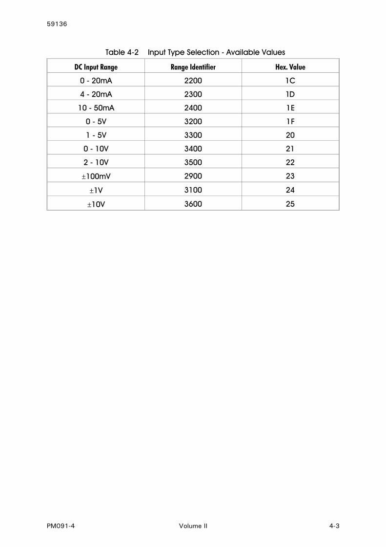
DC Input Range Range Identifier Hex. Value
0 - 20mA 2200 1C
4 - 20mA 2300 1D
10 - 50mA 2400 1E
0 - 5V 3200 1F
1 - 5V 3300 20
0 - 10V 3400 21
2 - 10V 3500 22
±100mV 2900 23
±1V 3100 24
±10V 3600 25
Table 4-2 Input Type Selection - Available Values

APPENDIX A PRODUCT SPECIFICATION
A.1 DISPLAY
Type: Red/green, 7-segment LED, 5-digit primarydisplay, 1-digit secondary display.
Height: 0.71 inches (18mm) primary display0.3 inches (7mm) secondary display
Annunciators: Alarm 1 and Alarm 2 status.
A.2 SENSOR INPUT
Type: DC. Ranges selectable:0 - 20mA, 4 - 20mA, 10 - 50mA0 - 5V, 1 - 5V, 0 - 10V, 2 - 10V±100mV, ±1V, ±10V
Accuracy: Typical ±0.01% of span; ±0.05% max.
Sample Rate: Every 100mS.
Resolution: 14 bits.
Sensor Break Detection: On 4 - 20mA, 10 - 50mA, 1 - 5V and 2 - 10V input ranges only; detected within twoseconds.
A.3 DIGITAL INPUT (OPTION)
Type: Voltage-free or TTL-compatible operation.
May be connected to: External switch/relay contacts orTTL-compatible logic signal.
Maximum Input delay(open - closed or “1" - “0"transition):
1 second
Minimum Input delay(closed - open or “0" - “1"transition):
1 second
A-1 Volume II PM091-A
59136
External Switch/Relay Contacts
Maximum Contact Resistance (Closure):50Ω
Minimum Contact Resistance (Open):5000Ω
External TTL-Compatible Logic Signal
Maximum Voltage (TTL) for “0”: 0.8V
Minimum Voltage (TTL) for “0": -0.6V
Minimum Voltage (TTL) for “1": 2.0V
Maximum Voltage (TTL) for “1": 24.0V
A.4 TRANSISTOR OUTPUTS
Type: NPN open collector. Output tied to Alarm 1, Output 2 tied to Alarm 2.
A.5 RELAY 1 OUTPUT
Contact Type: Single pole double throw.
Rating: 5A resistive @ 120/240V AC
Lifetime: >500,000 operations at ratedvoltage/current.
Isolation: Inherent
A.6 RELAY 2 OUTPUT (OPTION)
Contact Type: Single pole double throw.
Rating: 5A resistive @ 120/240V AC
Lifetime: >500,000 operations at ratedvoltage/current.
Isolation: Inherent
A.7 LINEAR (RE-TRANSMITTED PV) OUTPUT (OPTION)
Ranges available: 0 - 5V, 1 - 5V, 0 - 10V, 2 - 10V, 0 - 20mAand 4 - 20mA.
PM091-A Volume II A-2
59136

Accuracy: 0.25% (mA @ 250W, V @ 2kW); degradeslinearly to 0.5%.
Resolution: 8 bits in 250mS (10 bits in 1 secondtypically).
Update Rate: 4/second approximately.
Load Impedance: mA ranges - 500Ω max.V ranges - 500Ω min.
A.8 SERIAL COMMUNICATIONS (OPTION)
Type: Serial asynchronous, UART to UART.
Data Format: Open ASCII; One start bit, even parity,seven data bits, one stop bit.
Physical Layer: RS485.
Maximum Number ofZones:
99.
Baud Rate: Selectable from 1200, 2400, 4800 and9600 Baud.
A.9 PERFORMANCE
Reference Conditions
Ambient Temperature: 20°C ±2°C
Relative Humidity: 60 - 70%
Supply Voltage: 90 - 264V AC 50Hz)
Performance Under Reference Conditions
Common Mode Rejection: >120dB at 50/60Hz giving negligible effect at up to 264V 50/60Hz.
Series Mode Rejection: >500% of span (at 50/60Hz) causesnegligible effect.
DC Input
Measurement Accuracy: Typical ±0.01% of span ±1LSD; ±0.05% ofspan ±1LSD max.
A-3 Volume II PM091-A
59136

Operating Conditions
Ambient Temperature: 0°C to 55°C
Relative Humidity: 20% - 95% non-condensing
Performance Under Operating Conditions
Temperature Stability: 0.005% of span/°C change in ambienttemperature.
A.10 ENVIRONMENTAL
EMI Susceptibility: Complies with EN50082-1:1992,EN50082-1:1995.
NOTES:1. For RF electromagnetic fields (10V/m 80% AM 1kHz), the readingaccuracy may be impaired by up to −0.3% in the frequency band87 to 109MHz.2. For line-conducted disturbances induced by RF fields (10V 80%AM 1kHz), the product is self-recoverable in the frequency band0.15 - 0.73MHz.
EMI Emmissions: Complies with EN50081-1:1992,EN50081-2:1993.
Safety: Complies with EN61010-1.1993.
Supply Voltage: 90 - 264V, 50/60Hz (standard)20 - 50V AC/DC (option)
Power Consumption: 4watts approximately
Front Panel Sealing: To IP66 (Nema 4)
A.11 PHYSICAL
Dimensions: Height - 48mmWidth - 96mmDepth - 100mm
Mounting: Panel-mount; press-fit fixing strap supplied.Panel cut-out - 45mm x 92mm
Terminals: Screw type; combination head.
Weight: 0.21kg maximum.
PM091-A Volume II A-4
59136