Embed Size (px)
Citation preview


Development replaces permeable desert with impermeable roofs and pavement
Increases peak and total stormwater discharge
Classical approach: large engineering projects (lined canals, large ponds)
Newer approach: smaller distributed structures that mimic natural systems

Flash flood is spread over time
Leading to smoother hydrograph below
Natural hydrographs can be approximated
time
dis
charg
e

REDUCE OR ELIMINATE REPLACE WITH
Large retention ponds
Large detention ponds
Concrete lined channels
High cost Unsightly
Small systems distributed throughout the development
Bioretention/infiltration swales
Natural arroyos Lower cost Beautiful

Small scale controls mimic natural hydrologic processes
Directing runoff to natural areas encourages growth of trees and enhances infiltration
Conservation preserves natural drainage patterns
Customized site design protects the entire watershed
Capturing runoff in small volumes helps to prevent erosion, because the runoff is less likely to reach damaging flow rates.
The distribution of storage components also tends to result in a more robust stormwater management system, because the failure of one component will not cause the entire system to fail.
A knowledge based approach that requires full analysis of precipitation history (drought is important for vegetation, storms for flooding)

Bioretention: Vegetated depressions store water in soil and provide reliable water for drought resistant vegetation
Tree box filters: curbside containers placed below grade, covered with a grate and filled with sand and soil, with tree planted in middle
Infiltration trenches: fill areas with sorted gravel or rock to capture and infiltrate runoff
Permeable pavement: Asphalt or concrete that allows infiltration
Permeable pavers: manufactured paving stones containing spaces where water can penetrate
Disconnect impervious areas by directing runoff from buildings and pavements onto lawns or other vegetated areas
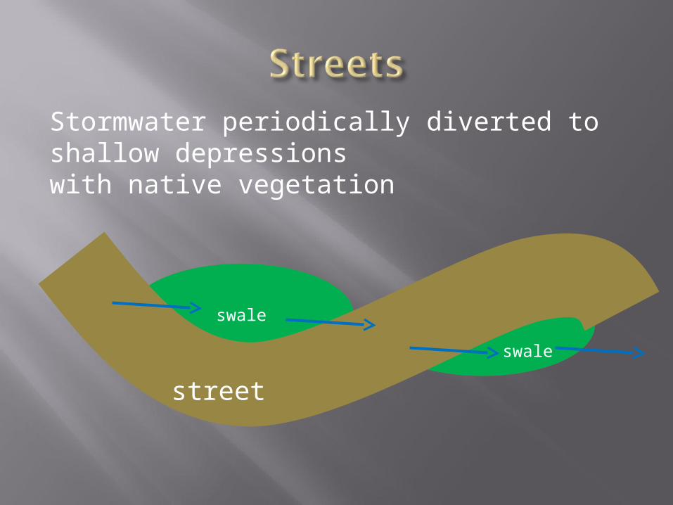
Use weirs and check dams in swales


swale
Stormwater periodically diverted to shallow depressions with native vegetation
swale
street


Arroyos move water and sediment Peak discharge causes flooding, not total
water Blockage of arroyos by retention/detention
ponds interrupts sediment flow, leading to erosion downstream
Retention ponds as specified by the city constitute a waste of resources
(Capture area/ plant area) > 15 supports vegetation with no watering in El Paso climate

nativeplants
Impermeable areas concentrate water in vegetated areasConsider that if rainfall is increased by 10X, El Paso has a lot of water for watering trees.
capture area
capture area/plant area > 15 for El Paso
Sediment transport and erosion are related Water has a sediment carrying capacity
that depends upon velocity When the capacity to carry sediment is
reached, erosion stops When sediments are artificially removed
from water by ponding, downstream erosion is increased
Detention ponds artificially deplete sediment

Peak discharge increased by upsteam development
Water comes in deficient in sediment Increased erosion visible ~1/2 mile below
major water inputs to canyon

Upstream development can cause increased erosion downstream from a) increased peak discharge and/orb) sediment “hungry” water


Use less city water since landscaping would be watered by rain
Have more vegetation Increase groundwater recharge Not increase downstream runoff or
erosion Be more profitable

Current stormwater engineering practices in El Paso are based primarily on dated designs from different climates and landscapes
Modern low impact designs focus on distributed points of infiltration and transpiration for reducing peak discharge
Site specific designs that reflect the unique geography and climate of the El Paso del Norte Region are needed
Modern designs can lower costs and increase profits for developers while preserving the environment and providing an improved living experience

Water is most economically stored in the soil, this water must lastthrough periods of drought
10 year simulation of soil moisture in a bio retention structure,El Paso climate


T=Transpiration=The water loss from plant.
E=Evaporation=The water loss due to the change of water from a liquid state to a vapor state
http://www.cimis.water.ca.gov/cimis/images/eto_overview.gif

Plant available water is exactly as the name implies, it is the unbound water that is available to plants for uptake.
This is calculated by subtracting the water content at field capacity from the soil water content at the permanent wilting point.
The field capacity and the wilting point differ from type of soil to another type.


If we have 65 cm3 of water at field capacity, and are left with 13 cm3 at the permanent wilting point, what is our plant available water?

SCS runoff curve number method (Soil-Cover Method).
Initial abstraction (Ia) is all losses before runoff begins. It includes water retained in surface depressions, water intercepted by vegetation, evaporation, and infiltration.
S is related to the soil and cover conditions of the watershed through the CN.
The major factors that determine CN are the hydrologic soil group (HSG), cover type, treatment, hydrologic condition, and antecedent runoff condition (ARC).

If the accumulative precipitation of a 100-year storm is 8 inches and the average CN fro the drainage area is 89. How many inches of runoff can be generated? How much water lost?
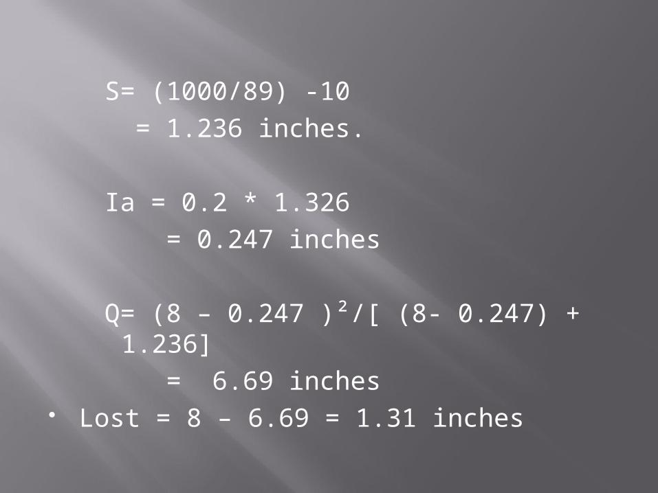
S= (1000/89) -10 = 1.236 inches.
Ia = 0.2 * 1.326 = 0.247 inches
Q= (8 – 0.247 )²/[ (8- 0.247) + 1.236] = 6.69 inches
Lost = 8 – 6.69 = 1.31 inches

Fro a 1000 sq ft. drainage area, the conditions of 500 sq ft are different where CN= 75 while CN of the rest of the area is 68. If the accumulated precipitation is 6.5 inches, how much runoff will be produced. Haw much water lost to interception, infiltration, evaporation, etc.